JP2004041733A - Suturing apparatus for endoscope - Google Patents
Suturing apparatus for endoscopeDownload PDFInfo
- Publication number
- JP2004041733A JP2004041733AJP2003194389AJP2003194389AJP2004041733AJP 2004041733 AJP2004041733 AJP 2004041733AJP 2003194389 AJP2003194389 AJP 2003194389AJP 2003194389 AJP2003194389 AJP 2003194389AJP 2004041733 AJP2004041733 AJP 2004041733A
- Authority
- JP
- Japan
- Prior art keywords
- endoscope
- puncture
- suturing device
- distal end
- treatment space
- Prior art date
- Legal status (The legal status is an assumption and is not a legal conclusion. Google has not performed a legal analysis and makes no representation as to the accuracy of the status listed.)
- Granted
Links
- 210000001519tissueAnatomy0.000description80
- 238000003780insertionMethods0.000description47
- 230000037431insertionEffects0.000description47
- 210000004400mucous membraneAnatomy0.000description15
- 230000010339dilationEffects0.000description14
- 238000002347injectionMethods0.000description13
- 239000007924injectionSubstances0.000description13
- 208000021302gastroesophageal reflux diseaseDiseases0.000description9
- 239000002184metalSubstances0.000description9
- 239000007788liquidSubstances0.000description8
- 239000000463materialSubstances0.000description8
- 238000012326endoscopic mucosal resectionMethods0.000description7
- 238000000034methodMethods0.000description7
- 239000004033plasticSubstances0.000description7
- 229920003023plasticPolymers0.000description7
- 238000005452bendingMethods0.000description6
- 210000002318cardiaAnatomy0.000description6
- 210000002784stomachAnatomy0.000description6
- 210000003238esophagusAnatomy0.000description5
- 210000000111lower esophageal sphincterAnatomy0.000description5
- 210000003205muscleAnatomy0.000description5
- 238000013459approachMethods0.000description4
- 201000010099diseaseDiseases0.000description4
- 208000037265diseases, disorders, signs and symptomsDiseases0.000description4
- 230000000694effectsEffects0.000description4
- 238000001356surgical procedureMethods0.000description4
- 239000004952PolyamideSubstances0.000description3
- 239000004698PolyethyleneSubstances0.000description3
- 239000004642PolyimideSubstances0.000description3
- 238000004519manufacturing processMethods0.000description3
- 230000002093peripheral effectEffects0.000description3
- 229920002647polyamidePolymers0.000description3
- -1polyethylenePolymers0.000description3
- 229920000573polyethylenePolymers0.000description3
- 229920001721polyimidePolymers0.000description3
- 229920002635polyurethanePolymers0.000description3
- 239000004814polyurethaneSubstances0.000description3
- 239000000243solutionSubstances0.000description3
- 229920002725thermoplastic elastomerPolymers0.000description3
- 238000001574biopsyMethods0.000description2
- 201000006549dyspepsiaDiseases0.000description2
- 208000024798heartburnDiseases0.000description2
- 239000007769metal materialSubstances0.000description2
- 210000004877mucosaAnatomy0.000description2
- 230000003387muscularEffects0.000description2
- HLXZNVUGXRDIFK-UHFFFAOYSA-Nnickel titaniumChemical compound[Ti].[Ti].[Ti].[Ti].[Ti].[Ti].[Ti].[Ti].[Ti].[Ti].[Ti].[Ni].[Ni].[Ni].[Ni].[Ni].[Ni].[Ni].[Ni].[Ni].[Ni].[Ni].[Ni].[Ni].[Ni]HLXZNVUGXRDIFK-UHFFFAOYSA-N0.000description2
- 229910001000nickel titaniumInorganic materials0.000description2
- 229920005989resinPolymers0.000description2
- 239000011347resinSubstances0.000description2
- 210000003786scleraAnatomy0.000description2
- 210000002151serous membraneAnatomy0.000description2
- 229910001220stainless steelInorganic materials0.000description2
- 239000010935stainless steelSubstances0.000description2
- 208000024891symptomDiseases0.000description2
- 230000001225therapeutic effectEffects0.000description2
- PXGOKWXKJXAPGV-UHFFFAOYSA-NFluorineChemical compoundFFPXGOKWXKJXAPGV-UHFFFAOYSA-N0.000description1
- 208000034991Hiatal HerniaDiseases0.000description1
- 206010020028Hiatus herniaDiseases0.000description1
- 206010028980NeoplasmDiseases0.000description1
- 239000004677NylonSubstances0.000description1
- 229920002292Nylon 6Polymers0.000description1
- 229920002302Nylon 6,6Polymers0.000description1
- 208000002193PainDiseases0.000description1
- FAPWRFPIFSIZLT-UHFFFAOYSA-MSodium chlorideChemical compound[Na+].[Cl-]FAPWRFPIFSIZLT-UHFFFAOYSA-M0.000description1
- 239000002253acidSubstances0.000description1
- 230000001154acute effectEffects0.000description1
- 239000000853adhesiveSubstances0.000description1
- 230000001070adhesive effectEffects0.000description1
- 239000000560biocompatible materialSubstances0.000description1
- 230000000740bleeding effectEffects0.000description1
- 201000011510cancerDiseases0.000description1
- 238000000576coating methodMethods0.000description1
- 239000003086colorantSubstances0.000description1
- 238000009500colour coatingMethods0.000description1
- 238000004891communicationMethods0.000description1
- 238000002224dissectionMethods0.000description1
- 239000003814drugSubstances0.000description1
- 229940079593drugDrugs0.000description1
- 239000011737fluorineSubstances0.000description1
- 229910052731fluorineInorganic materials0.000description1
- 210000004211gastric acidAnatomy0.000description1
- 230000027119gastric acid secretionEffects0.000description1
- 210000001035gastrointestinal tractAnatomy0.000description1
- 238000001802infusionMethods0.000description1
- 239000003112inhibitorSubstances0.000description1
- 238000001746injection mouldingMethods0.000description1
- 238000012986modificationMethods0.000description1
- 230000004048modificationEffects0.000description1
- JFNLZVQOOSMTJK-KNVOCYPGSA-NnorborneneChemical compoundC1[C@@H]2CC[C@H]1C=C2JFNLZVQOOSMTJK-KNVOCYPGSA-N0.000description1
- 229920001778nylonPolymers0.000description1
- 210000000056organAnatomy0.000description1
- 239000004417polycarbonateSubstances0.000description1
- 229920000515polycarbonatePolymers0.000description1
- 239000004810polytetrafluoroethyleneSubstances0.000description1
- 229920001343polytetrafluoroethylenePolymers0.000description1
- 230000002265preventionEffects0.000description1
- 229940126409proton pump inhibitorDrugs0.000description1
- 239000000612proton pump inhibitorSubstances0.000description1
- 239000010703siliconSubstances0.000description1
- 229910052710siliconInorganic materials0.000description1
- 239000011780sodium chlorideSubstances0.000description1
- 230000008961swellingEffects0.000description1
- 229920003002synthetic resinPolymers0.000description1
- 239000000057synthetic resinSubstances0.000description1
- 210000004876tela submucosaAnatomy0.000description1
- 238000003466weldingMethods0.000description1
Images


Classifications
- A—HUMAN NECESSITIES
- A61—MEDICAL OR VETERINARY SCIENCE; HYGIENE
- A61B—DIAGNOSIS; SURGERY; IDENTIFICATION
- A61B17/00—Surgical instruments, devices or methods
- A61B17/04—Surgical instruments, devices or methods for suturing wounds; Holders or packages for needles or suture materials
- A61B17/0401—Suture anchors, buttons or pledgets, i.e. means for attaching sutures to bone, cartilage or soft tissue; Instruments for applying or removing suture anchors
- A—HUMAN NECESSITIES
- A61—MEDICAL OR VETERINARY SCIENCE; HYGIENE
- A61B—DIAGNOSIS; SURGERY; IDENTIFICATION
- A61B17/00—Surgical instruments, devices or methods
- A61B17/04—Surgical instruments, devices or methods for suturing wounds; Holders or packages for needles or suture materials
- A61B17/0469—Suturing instruments for use in minimally invasive surgery, e.g. endoscopic surgery
- A—HUMAN NECESSITIES
- A61—MEDICAL OR VETERINARY SCIENCE; HYGIENE
- A61B—DIAGNOSIS; SURGERY; IDENTIFICATION
- A61B17/00—Surgical instruments, devices or methods
- A61B17/04—Surgical instruments, devices or methods for suturing wounds; Holders or packages for needles or suture materials
- A61B17/06—Needles ; Sutures; Needle-suture combinations; Holders or packages for needles or suture materials
- A61B17/06066—Needles, e.g. needle tip configurations
- A61B17/06109—Big needles, either gripped by hand or connectable to a handle
- A—HUMAN NECESSITIES
- A61—MEDICAL OR VETERINARY SCIENCE; HYGIENE
- A61B—DIAGNOSIS; SURGERY; IDENTIFICATION
- A61B17/00—Surgical instruments, devices or methods
- A61B17/064—Surgical staples, i.e. penetrating the tissue
- A—HUMAN NECESSITIES
- A61—MEDICAL OR VETERINARY SCIENCE; HYGIENE
- A61B—DIAGNOSIS; SURGERY; IDENTIFICATION
- A61B17/00—Surgical instruments, devices or methods
- A61B17/064—Surgical staples, i.e. penetrating the tissue
- A61B17/0643—Surgical staples, i.e. penetrating the tissue with separate closing member, e.g. for interlocking with staple
- A—HUMAN NECESSITIES
- A61—MEDICAL OR VETERINARY SCIENCE; HYGIENE
- A61B—DIAGNOSIS; SURGERY; IDENTIFICATION
- A61B17/00—Surgical instruments, devices or methods
- A61B17/28—Surgical forceps
- A61B17/29—Forceps for use in minimally invasive surgery
- A—HUMAN NECESSITIES
- A61—MEDICAL OR VETERINARY SCIENCE; HYGIENE
- A61B—DIAGNOSIS; SURGERY; IDENTIFICATION
- A61B17/00—Surgical instruments, devices or methods
- A61B17/00234—Surgical instruments, devices or methods for minimally invasive surgery
- A61B2017/00238—Type of minimally invasive operation
- A61B2017/00269—Type of minimally invasive operation endoscopic mucosal resection EMR
- A—HUMAN NECESSITIES
- A61—MEDICAL OR VETERINARY SCIENCE; HYGIENE
- A61B—DIAGNOSIS; SURGERY; IDENTIFICATION
- A61B17/00—Surgical instruments, devices or methods
- A61B17/00234—Surgical instruments, devices or methods for minimally invasive surgery
- A61B2017/00353—Surgical instruments, devices or methods for minimally invasive surgery one mechanical instrument performing multiple functions, e.g. cutting and grasping
- A—HUMAN NECESSITIES
- A61—MEDICAL OR VETERINARY SCIENCE; HYGIENE
- A61B—DIAGNOSIS; SURGERY; IDENTIFICATION
- A61B17/00—Surgical instruments, devices or methods
- A61B17/04—Surgical instruments, devices or methods for suturing wounds; Holders or packages for needles or suture materials
- A61B17/0401—Suture anchors, buttons or pledgets, i.e. means for attaching sutures to bone, cartilage or soft tissue; Instruments for applying or removing suture anchors
- A61B2017/0409—Instruments for applying suture anchors
- A—HUMAN NECESSITIES
- A61—MEDICAL OR VETERINARY SCIENCE; HYGIENE
- A61B—DIAGNOSIS; SURGERY; IDENTIFICATION
- A61B17/00—Surgical instruments, devices or methods
- A61B17/04—Surgical instruments, devices or methods for suturing wounds; Holders or packages for needles or suture materials
- A61B17/0401—Suture anchors, buttons or pledgets, i.e. means for attaching sutures to bone, cartilage or soft tissue; Instruments for applying or removing suture anchors
- A61B2017/0417—T-fasteners
- A—HUMAN NECESSITIES
- A61—MEDICAL OR VETERINARY SCIENCE; HYGIENE
- A61B—DIAGNOSIS; SURGERY; IDENTIFICATION
- A61B17/00—Surgical instruments, devices or methods
- A61B17/04—Surgical instruments, devices or methods for suturing wounds; Holders or packages for needles or suture materials
- A61B17/0401—Suture anchors, buttons or pledgets, i.e. means for attaching sutures to bone, cartilage or soft tissue; Instruments for applying or removing suture anchors
- A61B2017/0419—H-fasteners
- A—HUMAN NECESSITIES
- A61—MEDICAL OR VETERINARY SCIENCE; HYGIENE
- A61B—DIAGNOSIS; SURGERY; IDENTIFICATION
- A61B17/00—Surgical instruments, devices or methods
- A61B17/04—Surgical instruments, devices or methods for suturing wounds; Holders or packages for needles or suture materials
- A61B17/0469—Suturing instruments for use in minimally invasive surgery, e.g. endoscopic surgery
- A61B2017/0472—Multiple-needled, e.g. double-needled, instruments
- A—HUMAN NECESSITIES
- A61—MEDICAL OR VETERINARY SCIENCE; HYGIENE
- A61B—DIAGNOSIS; SURGERY; IDENTIFICATION
- A61B17/00—Surgical instruments, devices or methods
- A61B17/04—Surgical instruments, devices or methods for suturing wounds; Holders or packages for needles or suture materials
- A61B17/06—Needles ; Sutures; Needle-suture combinations; Holders or packages for needles or suture materials
- A61B17/06066—Needles, e.g. needle tip configurations
- A61B2017/061—Needles, e.g. needle tip configurations hollow or tubular
- A—HUMAN NECESSITIES
- A61—MEDICAL OR VETERINARY SCIENCE; HYGIENE
- A61B—DIAGNOSIS; SURGERY; IDENTIFICATION
- A61B17/00—Surgical instruments, devices or methods
- A61B17/064—Surgical staples, i.e. penetrating the tissue
- A61B2017/0647—Surgical staples, i.e. penetrating the tissue having one single leg, e.g. tacks
- A—HUMAN NECESSITIES
- A61—MEDICAL OR VETERINARY SCIENCE; HYGIENE
- A61B—DIAGNOSIS; SURGERY; IDENTIFICATION
- A61B17/00—Surgical instruments, devices or methods
- A61B17/28—Surgical forceps
- A61B17/29—Forceps for use in minimally invasive surgery
- A61B2017/2901—Details of shaft
- A61B2017/2905—Details of shaft flexible
Landscapes
- Health & Medical Sciences (AREA)
- Surgery (AREA)
- Life Sciences & Earth Sciences (AREA)
- Medical Informatics (AREA)
- Nuclear Medicine, Radiotherapy & Molecular Imaging (AREA)
- Engineering & Computer Science (AREA)
- Biomedical Technology (AREA)
- Heart & Thoracic Surgery (AREA)
- Molecular Biology (AREA)
- Animal Behavior & Ethology (AREA)
- General Health & Medical Sciences (AREA)
- Public Health (AREA)
- Veterinary Medicine (AREA)
- Rheumatology (AREA)
- Surgical Instruments (AREA)
- Endoscopes (AREA)
Abstract
Description
Translated fromJapanese【0001】
【発明の属する技術分野】
本発明は、経内視鏡的に生体の体腔内に挿入して、生体組織を縫合あるいは結紮する内視鏡用縫合装置に関する。特に、消化管において組織の損傷部位の治療や出血部の確実な止血のための縫合、胃食道逆流症の治療のための人工的な弁形成を行うための内視鏡用縫合装置に関する。
【0002】
【従来の技術】
現在、患者の体内の組織を縫合する場合、一般的に外科手術によって行われている。しかし、外科手術の場合、当然ながら患者の体を切開する必要があり、患者への侵襲が大きい。また、手術後の入院が必要であり、その入院費用などのコスト面での患者への負担も大きい。
【0003】
このような状況の中、患者の体を切開する必要がない低侵襲な経口的内視鏡による治療法の確立が望まれている。
【0004】
また、胃食道逆流症(Gastro esophageal Reflux Disease=GERD)は、近年、患者数が増加傾向にある疾患の一つである。主な症状としてHeartburn(胸やけ)、食道内のmucosal break(粘膜損傷)を有し、良性疾患でありながら患者の苦痛が大きいことから治療を必要とする患者が非常に多いことが特徴である。主な原因としては食道下部に存在する括約筋(Lower Esophageal Sphincter=LES)の機能が低下し、胃酸が食道内に逆流することにより発生する。
【0005】
GERDの治療は主にプロトンポンプインヒビター等の胃酸分泌抑制剤の投与が行なわれている。軽度のGERDであれば症状も改善し、根治も期待できる。しかし、LESの機能が著しく低下したケース、または裂孔ヘルニア等の解剖学的問題を抱えた重症のケースでは薬物による治療効果が小さく、また継続約な投与が必要なためコストがかかるという問題点がある。よって重症のGERDでは外科手術が適用される。効果的な術式としてNissen fundoplicationやToupet法が広く行なわれている。
【0006】
これらはいずれもLES部分を胃壁で包むことによりLESの機能改善を行なうもので、高い治療効果を有する。また、最近では腹腔鏡の術式も確立し、より低侵襲な治療が可能となっている。しかし、患者数が非常に多いこと、また癌と違い良性疾患であることから、より低侵襲な経口的内視鏡による治療法の確立が望まれている。その1つの手技として、生体組織を結紮して膨瘤させることで人工的な弁を形成することにより、胃酸の逆流を防止する内視鏡用縫合装置が知られている(例えば、特許文献1〜3参照。)。
【0007】
特許文献1及び2は、内視鏡の遠位端に縫合装置が設けられている。この縫合装置は、生検チャンネルと吸引チャンネルと連通する、側部に開口部を有するキャビティを備えている。そして、吸引チャンネルを介してキャビティを減圧吸引して生体組織の一部をU形にキャビティ内に吸引するとともに、生検チャンネル内の針及び糸搬送具が生体組織のU形部を穿刺して縫合するようになっている。
【0008】
また、特許文献3は、内視鏡の先端構成部にキャップが設けられ、このキャップの側部に開口部を有するキャビティが設けられている。先端構成部にはシースの先端部に設けられた把持鉗子によって縫合具が把持されている。
【0009】
そして、生体組織をキャップの側部に設けられた開口部からキャビティに吸引するとともに、把持鉗子によって縫合具を生体組織に穿刺するようになっている。
【0010】
【特許文献1】
特表平10−500318号公報
【0011】
【特許文献2】
特公平6−44,913号公報
【0012】
【特許文献3】
特開平11−313,826号公報
【0013】
【発明が解決しようとする課題】
しかしながら、特許文献1〜3は、いずれも内視鏡の先端構成部の側部に開口部を有するキャビティに生体組織を吸引するように構成されている。
【0014】
従って、キャビティの開口部を生体組織の目的部位に押し付け、キャビティを減圧吸引しなくてはならない。従って、キャビティの開口部を目的部位にアプローチし難いとともに、キャビティを減圧吸引しただけでは生体組織を十分にキャビティの内部に引き込むことはできない。
【0015】
また、例えば胃食道逆流症の治療のために人工的な弁を形成するために生体組織を縫合する際には胃の一部を吸引する必要があるが、胃壁は食道などの組織と比べて厚く、また内腔側の粘膜層(mucous membrane),中間の筋層(proper muscularis),外皮側の漿膜(serous membrane)に分かれており、特に粘膜層と筋層の間は高い流動性を有する。また、弁として機能させる規模の隆起を形成するには筋層を取り込んだ上で組織を短縮、隆起させることが必須である。しかし、従来の装置では粘膜層を取り込むことができてもその下に位置する筋層を取り込むのが困難である。よって本構成にて形成した弁では大きさ、厚さが不足し、十分な逆流防止効果が得られない可能性が高い。同様に、例えば損傷部位の確実な縫合を行うためには、組織の筋層あるいは奨膜までを含めて縫合してやることが必須であるが、従来の装置では筋層あるいは奨膜を取り込むのが困難である。
【0016】
本発明は、生体組織の目的部位にアプローチしやすく、生体組織を保持部内に取り込んで縫合できる内視鏡用縫合装置を提供することにある。
【0017】
【課題を解決するための手段】
本発明は、前記目的を達成するために、内視鏡と、少なくとも1つの尖端を有する穿刺部材と、前記穿刺部材を保持して、かつ前記内視鏡の先端に着脱自在な保持部材と、内視鏡に対して進退自在で、かつ組織を把持可能な把持部材と、前記穿刺部材を移動させる移動部材とからなる内視鏡用縫合装置において、前記穿刺部材は、先端側に向けて開口する開口部を有しており、その開口部と前記内視鏡先端と前記保持部材に囲まれた処置用空間を形成しており、前記把持部材は、前記処置用空間を通って前記開口部から突没可能となっており、前記穿刺部材は、内視鏡の長手方向に対して横断する方向に前記処置用空間を移動可能となっている内視鏡用縫合装置にある。
【0018】
また、本発明は、生体組織を把持するための、内視鏡の長手方向に移動自在な把持部材と、前記把持部材が把持した生体組織に穿刺される穿刺部材と、前記穿刺部材を前記把持部材の移動方向と交差する方向に移動し、前記穿刺部材を前記生体組織に穿刺する穿刺部材駆動部材を具備した内視鏡用縫合装置にある。
【0019】
【発明の実施の形態】
以下、本発明の各実施の形態を図面に基づいて説明する。
【0020】
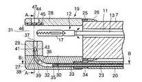
図1〜図10は内視鏡用縫合装置の第1の実施形態を示し、図1に示す内視鏡1は、操作部2と、可撓性を有する挿入部3及びユニバーサルコード4とから構成されている。挿入部3は可撓管部5と湾曲管部6及び先端構成部7とから構成されている。操作部2には湾曲操作部9及び鉗子栓10が設けられている。
【0021】
鉗子栓10は、図2に示すように、挿入部3を介して先端構成部7に連通する鉗子チャンネル11に連通している。鉗子栓10には把持部材としての把持鉗子12のシース13が挿通されている。シース13は、例えば金属製の多条コイルまたはブレード入りプラスチックチューブからなり、このシース13の近位端には操作部本体14が設けられ、この操作部本体14にはスライダ15及び指掛けリング16が設けられている。
【0022】
把持鉗子12の遠位端には挟み鉗子形状の把持部17が設けられ、この把持部17はスライダ15の進退操作によって開閉するようになっている。さらに、把持部17は操作部本体14の回転操作によって鉗子チャンネル11内で回転でき、把持部17の向きを変えることができる。
【0023】
また、内視鏡1の挿入部3には穿刺装置18が設けられている。この穿刺装置18は、内視鏡1の先端構成部7に着脱可能に装着される保持部材としてのキャップ19と、シース20及び穿刺操作部21とから構成されている。シース20は挿入部3の屈曲に追従可能なように可撓性を有する材料、例えば、フッ素樹脂、ポリエチレン、ポリアミド、ポリイミド、ポリウレタン、各種熱可塑性エラストマーなどのプラスチックチューブや金属製コイルで形成されている。キンクし難くするために金属製メッシュ入りのプラスチックチューブでも良い。
【0024】
このシース20は、医療用テープ22によって内視鏡1の挿入部3に固定され、穿刺操作部21は把持鉗子12の操作部本体14の近傍に保持されている。このシース20の先端にはシース接続部34が連結されている。
【0025】
シース20には移動部材(穿刺部材駆動部材)としてのプッシャ部材23が進退自在に内装されている。このプッシャ部材23は金属撚り線等からなり、この近位端は穿刺操作部21の操作スライダ24と連結されている。
【0026】
前記キャップ19は、比較的硬質の材料で形成されており、特に内視鏡の視野を妨げないようにポリカーボネート、ノルボルネン樹脂などの透明性に優れた材料で形成されていることが望ましい。キャップ19は、略矩形ボックス形状で、この基端部には連結部材25を介して円筒状の装着部26が設けられている。そして、装着部26を先端構成部7に嵌合することにより、キャップ19が内視鏡1に着脱自在に取付けられている。
【0027】
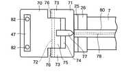
図2及び図3に示すように、キャップ19には、左右に2分割された平板状の下部ベース27と平板状の上部ベース28とが互いに対向して設けられている。さらに、下部ベース27の先端部には上部ベース28に向かって突出する先端ベース29が設けられている。従って、キャップ19の内部には下部ベース27と上部ベース28及び先端ベース29によって囲まれる処置用空間30が設けられている。さらに、下部ベース27と上部ベース28との間には先端側に向かって開口する開口部31が処置用空間30に連通して設けられている。この開口部31は先端構成部7の鉗子チャンネル11と対向し、把持部17が突没できるように構成されている。
【0028】
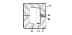
図4に示すように、前記キャップ19の下部ベース27には左右方向に幅広で、上下方向に狭幅のガイド内腔32が設けられている。このガイド内腔32の基端部における幅方向の中間部には前記穿刺装置18のシース20と対向する貫通穴33が設けられている。この貫通穴33にはシース接続部34がねじ込み固定されており、シース20と接続されている。従って、シース20に挿通されたプッシャ部材23はシース接続部34を貫通してガイド内腔32まで延長している。
【0029】
図5に示すように、プッシャ部材23の遠位端にはガイド内腔32の内部で進退自在なプッシャ35が連結されている。このプッシャ35はプッシャ部材23に対して直角方向に固定された角棒状部材であり、ガイド内腔32の幅方向に延長している。
【0030】
ガイド内腔32の先端側は上方に向かって円弧状に湾曲する湾曲ガイド内腔36を有しており、この湾曲ガイド内腔36は先端ベース29に設けられた扁平状の垂直ガイド内腔37と連通している。
【0031】
湾曲ガイド内腔36の内部には1個の穿刺部材としてのステープル38が収容されている。ステープル38は、図6に示すように、例えば、ニチノール、ステンレス等の弾性復元力を有する金属材料によって略コ字状に形成されている。すなわち、ステープル38は基部39に対して直角に一対の脚部40が平行して設けられ、脚部40の両先端部には尖端41が設けられている。この尖端41は矢尻形状または円錐形状で、基端面には係止面42が形成されている。
【0032】
そして、湾曲ガイド内腔36に収容されたステープル38の尖端41の斜面が垂直ガイド内腔37の内周面に形成された凸条部43に接触し、ステープル38が不用意に飛び出さないように位置決めされている。
【0033】
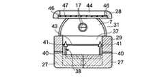
さらに、垂直ガイド内腔37に対向する上部ベース28には側口44が設けられ、この側口44の内周面における基端側には溝部45が設けられ、両側及び先端側には段差からなる受け部46が設けられている。そして、側口44にはこれを閉塞するように受けシート47が設けられ、この受けシート47の外周縁の一辺は溝部45に着脱自在に挿入され、残りの三辺は受け部46に支持されている。この受けシート47は、例えば、ナイロン、フッ素、シリコン等の生体親和性の良く、かつ可撓性を有する樹脂シートによって形成され、ステープル38によって穿刺されるようになっている。
【0034】
次に、第1の実施形態の作用について説明する。
【0035】
まず、図2に示すように、内視鏡1の挿入部3にシース20を医療用テープ22によって固定するとともに、先端構成部7にキャップ19の装着部26を装着する。このとき、先端構成部7の鉗子チャンネル11の開口とキャップ19の開口部31とを対向させる。さらに、キャップ19の湾曲ガイド内腔36の内部にステープル38を収容するとともに、穿刺装置18のシース20とキャップ19の貫通穴33とをシース接続部34によって接続する。
【0036】
この状態で、内視鏡1の挿入部3を経口的に患者の体腔内に挿入し、内視鏡観察下で、湾曲操作部9を操作して先端構成部7を縫合部位に導く。縫合部位が図7に示すように、生体組織の切開傷50であって、この切開傷50を挟んで両側の組織部50a,50bを縫合する場合、キャップ19の開口部31を切開傷50に接近して対向させる。
【0037】
次に、把持鉗子12の操作部本体14を操作してシース13を前進させ、把持部17をキャップ19の処置用空間30から開口部31を介してキャップ19の前方に突出させる。このとき、操作部本体14を回すことにより、シース13を介して把持部17の向きを調整して組織部50a,50bに対向させることができる。
【0038】
この状態で、指掛けリング16とスライダ15に手指を掛け、スライダ15を前方へ移動させることにより、把持部17を開き、把持部17を組織部50a,50bに押し当てる。次に、スライダ15を後方へ移動させると、把持部17が閉じ、把持部17によって組織部50a,50bを把持する。
【0039】
次に、図8に示すように、操作部本体14を手前側に引き込むと、シース13を介して把持部17が後退し、把持部17によって把持した組織部50a,50bを開口部31からキャップ19の処置用空間30に引き込むことができる。この状態で、穿刺装置18の穿刺操作部21を支持した状態で、操作スライダ24を前進させると、プッシャ部材23がシース20内を前進する。
【0040】
プッシャ部材23の前進によってプッシャ35がガイド内腔32から湾曲ガイド内腔36方向に前進し、湾曲ガイド内腔36に収容されているステープル38の基部39に当接する。プッシャ35をさらに前進させると、ステープル38の尖端41は垂直ガイド内腔37の凸条部43を乗り越え、垂直ガイド内腔37から開口部31に突出する。
【0041】
従って、図9に示すように、ステープル38はキャップ19の処置用空間30に引き込まれた組織部50a,50bに穿刺され、尖端41は組織部50a,50bを貫通し、さらに受けシート47を貫通する。
【0042】
このとき、ステープル38が組織部50a,50bを貫通する際、ステープル38の移動方向に組織部50a,50bが押されるが、上部ベース28が押さえとなり、確実に貫通するという効果がある。
【0043】
この状態で、把持鉗子12のスライダ15を前方へ移動させて把持部17を開くと、組織部50a,50bは把持部17から開放される。次に、内視鏡1の挿入部3を後退させると、キャップ19の溝部45から受けシート47が抜け、受けシート47がキャップ19と分離される。
【0044】
従って、図10に示すように、組織部50a,50bにステープル38の一対の脚部40が貫通し、一方の組織部50bに基部39が接し、他方の組織部50aに受けシート47を介して尖端41が接した状態となる。しかも、尖端41の係止面42は受けシート47に面接触した状態となり、尖端41は受けシート47及び組織部50a,50bから抜けるのを防止することができる。
【0045】
本実施形態によれば、キャップ19を目的部位にアプローチしやすく、また、把持鉗子12によって組織部50a,50bをキャップ19の開口部31から内部に引き込んだ状態で、開口部31を横断するステープル38によって組織部50a,50bを縫合することができる。従って、目的部位を確実に縫合できる。
【0046】
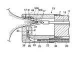
図11及び図12は第2の実施形態を示し、第1の実施形態に示す、内視鏡用縫合装置を用いて胃食道逆流症(Gastro esophageal Reflux Disease=GERD)の治療に適用したもので、噴門部61に膨瘤部62を形成する場合について説明する。図11に示すように、内視鏡1の挿入部3を経口的に患者の食道63に挿入し、胃64に到達したところで、胃64の内部で湾曲管部6を略U字状に湾曲して先端構成部7を噴門部61に対向させる。内視鏡1によって噴門部61を見上げ、観察する。
【0047】
次に、第1の実施形態と同様に、把持鉗子12の操作部本体14を操作して把持部17をキャップ19の前方に突出させ、噴門部61の大湾側組織65を把持部17によって把持する。そして、大湾側組織65を把持部17によってキャップ19の処置用空間30に引き込み、大湾側組織65にステープル38を穿刺して縫合することにより、図12に示すように、大湾側組織65に膨瘤部62を形成することができる。
【0048】
図13〜図18は第3の実施形態を示し、第1の実施形態と同一構成部分は同一番号を付して説明を省略する。図14及び図15に示すように、第1の実施形態におけるキャップ19の上部ベース28に相当する可動ベース70は、支持ベース71に対して枢支ピン72によって上下方向に回動自在に支持されている。
【0049】
すなわち、支持ベース71には平面視でコ字状に形成され、一対の支持アーム73の間には嵌合凹部74が形成されている。可動ベース70の基端部には嵌合凹部74に嵌合される嵌合凸部75が設けられている。この嵌合凸部75には前記枢支ピン72が貫通して設けられ、この枢支ピン72の両端部が支持アーム73に設けられたピン孔76に回動自在に挿入されている。
【0050】
可動ベース70の嵌合凸部75の基端部には斜め上方に突出する腕部77が一体に設けられ、この腕部77は操作ワイヤ78の遠位端と連結されている。腕部77と支持ベース71との間には板ばね、捩じりばね等の付勢ばね79が設けられ、可動ベース70を下部ベース27と平行となるように下方へ付勢している。
【0051】
操作ワイヤ78は連結部材25に連結されたシース80に進退自在に挿通され、内視鏡1の挿入部3に沿って操作部2まで導かれている。シース80は、挿入部3の屈曲に追従可能なように可撓性を有する材料、例えば、フッ素樹脂、ポリエチレン、ポリアミド、ポリイミド、ポリウレタン、各種熱可塑性エラストマーなどのプラスチックチューブや金属製コイルで形成されている。キンクし難くするために金属製メッシュ入りのプラスチックチューブでも良い。シース80は、シース91と同様ら挿入部3に沿った状態で医療用テープによって固定されている。
【0052】
そして、操作ワイヤ78の近位端には牽引操作部81が設けられている。従って、牽引操作部81によって操作ワイヤ78を牽引すると、腕部77は付勢ばね79の付勢力に抗して押し下げられ、枢支ピン72を支点として可動ベース70の先端側が上方に回動して開口部31が上方に大きく開口するようになっている。
【0053】
また、可動ベース70に設けられた側口44は受けシート47によって閉塞されており、この受けシート47にはステープル38の尖端41に対応して砲弾形状のカバー部82が一体に設けられている。このカバー部82に対向する受けシート47には小孔83が設けられ、この小孔83はカバー内腔84と連通している。そして、ステープル38の尖端41は小孔83を貫通してカバー内腔84に挿入され、係止面42は小孔83の口縁85に係止されるようになっている。
【0054】
次に、第3の実施形態の作用について説明するが、第1の実施形態と共通する部分については説明を省略する。把持部17をキャップ19の前方に突出させ、把持部17によって組織部50a,50bを把持する際、牽引操作部81によって操作ワイヤ78を牽引する。
【0055】
操作ワイヤ78が牽引されると、腕部77は付勢ばね79の付勢力に抗して押し下げられ、枢支ピン72を支点として可動ベース70の先端側が上方に回動して開口部31が上方に大きく開口する。
【0056】
そして、把持部17によって把持した組織部50a,50bを開口部31からキャップ19の処置用空間30に引き込むことにより、組織部50a,50bを広範囲に亘ってキャップ19の処置用空間30に引き込むことができる。
【0057】
この状態で、穿刺装置18の穿刺操作部21を支持して操作スライダ24を前進させると、プッシャ部材23を介してプッシャ35によってステープル38が前進し、ステープル38の尖端41は垂直ガイド内腔37の凸条部43を乗り越え、垂直ガイド内腔37から開口部31に突出する。
【0058】
従って、ステープル38はキャップ19の処置用空間30に引き込まれた組織部50a,50bに穿刺され、尖端41は組織部50a,50bを貫通する。尖端41は、さらに受けシート47の小孔83を貫通してカバー内腔84に挿入される。そして、尖端41の係止面42は小孔83の口縁85に係止され、抜け止めされる。
【0059】
本実施形態によれば、可動ベース70によってキャップ19の開口部31を大きく開口させて組織部50a,50bを広範囲に亘ってキャップ19内に引き込むことができる。また、受けシート47のステープル38の尖端41を収納するカバー部82を設けることにより、ステープル38の尖端41が体腔内に露出することはなく、他の組織を保護することができる。なお、本実施形態では、上部ベース28に相当する可動ベース70が回動するようにしたが、下部ベース27を回動する構成でもよい。
【0060】
なお、図18は受けシート47の変形例を示すもので、受けシート47の小孔83の周辺からカバー部82の側壁に連続してスリット86を設けたものである。このようにスリット86を設けることによってステープル38の尖端41が受けシート47の小孔83を貫通する際に、スリット86が拡開するため、尖端41が受けシート47を貫通する際の抵抗を軽減させることができる。
【0061】
図19〜図25は第4の実施形態を示し、第1の実施形態と同一構成部分は同一番号を付して説明を省略する。内視鏡1の挿入部3には穿刺装置90が設けられている。この穿刺装置90は、内視鏡1の挿入部3に沿って設けられた2本のシース91、これらシース91に進退自在に挿通された中空針92及び中空針92に進退自在に挿通された金属製ワイヤ等からなるプッシャ部材93と、シース91、中空針92及びプッシャ部材93の近位端に設けられた穿刺操作部94とから構成されている。
【0062】
シース91は挿入部3の屈曲に追従可能なように可撓性を有する材料、例えば、フッ素樹脂、ポリエチレン、ポリアミド、ポリイミド、ポリウレタン、各種熱可塑性エラストマーなどのプラスチックチューブや金属製コイルで形成されている。キンクし難くするために金属製メッシュ入りのプラスチックチューブでも良い。中空針92は、例えば、ニチノール、ステンレス等の弾性復元力を有する金属材料によって形成されている。
【0063】
穿刺操作部94は、2本のシース91の近位端に設けられ両シース91を結合する操作部本体95と、2本の中空針92の近位端に設けられ両中空針92を結合して同時に進退させる針スライダ96及び2本のプッシャ部材93の近位端に設けられ両プッシャ部材93を結合して同時に進退させるプッシャスライダ97とから構成されている。
【0064】
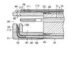
前記キャップ19の下部ベース27には2本の中空針92に対応して2本のガイド内腔98が設けられている。このガイド内腔98は湾曲ガイド内腔99を介して先端ベース29に設けられた垂直ガイド内腔100に連通している。そして、中空針92がガイド内腔98、湾曲ガイド内腔99及び垂直ガイド内腔100を進退するようになっている。この垂直ガイド内腔100の内側、すなわちキャップ19の処置用空間30側には上下方向にスリット101が設けられている。
【0065】
中空針92は、図23(B)に示すように、先端部が組織部50a,50bに穿刺しやすいように鋭角にカットされているとともに、先端部から軸方向にスリット102が設けられている。そして、この中空針92の先端部にはステープル103が収納されている。
【0066】
ステープル103は可撓性を有し、生体適合性に優れた材料、例えば6ナイロン、66ナイロン等の合成樹脂材料によって形成され、一対の棒状のストッパ部材104と、これらストッパ部材104を連結するコ字状のブリッジ部105とから構成されている。
【0067】
ステープル103は次のような製法で形成される。図23(C)のように中央部116の両端にストッパ部材104が一体に設けられたH形部材117を射出成形により形成する。その後、中央部116を延伸した後、その部分をコ字状に熱成形することでブリッジ部105を形成する。中央部116の延伸率は120〜500%であると望ましい。このような製法で形成することで、ストッパ部材104とブリッジ部105が一体で形成できることで製造コストが安くなるとともに、ブリッジ部105は延伸されているので引張り強度も高くなる。そして、ステープル103のストッパ部材104は中空針92の先端部から内部に挿入され、ブリッジ部105はスリット102から外部に突出している。
【0068】
次に、第4の実施形態の作用について説明する。
【0069】
把持部17によって組織部50a,50bを把持し、キャップ19の処置用空間30に引き込む作用は第1の実施形態と同じである。組織部50a,50bをキャップ19の処置用空間30に引き込んだ後、穿刺操作部94の針スライダ96を前進させると、2本の中空針92が同時に前進し、中空針92がガイド内腔98、湾曲ガイド内腔99及び垂直ガイド内腔100にガイドされながら前進する。そして、図24に示すように、ステープル103を収納した中空針92が組織部50a,50bを貫通して側口44から突出する。
【0070】
この状態で、プッシャスライダ97を前進させると、中空針92の内部をプッシャ部材93が前進する。そして、プッシャ部材93の先端部でステープル103のストッパ部材104を押し進める。ストッパ部材104が中空針92の先端部から突出すると、ストッパ部材104が弾性復元力でブリッジ部105に対して直角になり側口44の内部に位置する。
【0071】
次に、針スライダ96を後退させ、中空針92を組織部50a,50bから引抜くと、組織部50a,50bにステープル103だけが残り、図25に示すように、一方の組織部50aの側面にストッパ部材104が接触し、他方の組織部50bの側面にブリッジ部105が接触して抜け止めされて縫合が完了する。
【0072】
なお、ステープル103はストッパ部材104を一体に持っているので、第1の実施形態のように、別体の受けシート47を上部ベース28側に配置する必要がない。従って、本実施形態によれば、上部ベース28を設けなくても縫合が可能である。
【0073】
図26及び図27は第5の実施形態を示し、第1及び第4の実施形態と同一構成部分は同一番号を付して説明を省略する。
【0074】
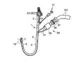
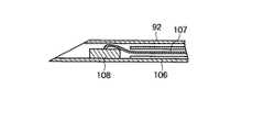
2本の中空針92の内部にはパイプ状のプッシャ部材106が進退自在に挿通されていて、このプッシャ部材106の近位端はプッシャスライダ97に接続されている。2本のプッシャ部材106にはそれぞれ縫合糸107が挿通されている。縫合糸107の近位端はプッシャスライダ97から外部に導出している。縫合糸107の遠位端は中空針92の先端部に収納された棒状のストッパ部材108の長手方向の中間部に接続されている。
【0075】
次に、第5の実施形態の作用について説明する。
【0076】
把持部17によって組織部50a,50bを把持し、キャップ19の処置用空間30に引き込んだ後、組織部50a,50bに2本の中空針92を穿刺する作用は第4の実施形態と同じである。
【0077】
本実施形態は、針スライダ96を後退させ、中空針92を組織部50a,50bから引抜くと、組織部50a,50bに縫合糸107が穿刺した状態でストッパ部材108が残り、ストッパ部材108が一方の組織部50aの側面に接触した状態となる。
【0078】
次に、内視鏡1の挿入部3を患者の体腔内から抜取ると、2本の縫合糸107の近位端が患者の体外に露出した状態となる。そこで、患者の体外で縫合糸107を結び、結び目(図示しない)を形成する。この結び目は一般的に外科手術で用いられている結び目であればどのようなものでもよい。
【0079】
その結び目を内視鏡1の鉗子チャンネル11に挿通するとともに、内視鏡1を患者の体腔内に挿入し、一般的なノットプッシャを用いて患者の体腔内に押し進める。結び目が組織部50bの近傍に到達したら、ノットプッシャを組織部50bに押し付け、同時に縫合糸107の両端を牽引して結び目を固定する。
【0080】
以上の操作を1回もしくは複数回繰り返し、結び目が解けないように強固に固定し、最後に内視鏡用鋏鉗子等によって結び目より手元側の縫合糸107を切断し、余った縫合糸107を体外に回収する。その後、内視鏡1及びノットプッシャを患者の体外に引抜くことにより縫合が完了する。
【0081】
本実施形態によれば、組織部50a,50bの大きさ、特に肉厚に応じた縫合糸107の長さに設定して結び目を付けることができ、組織部50a,50bを確実に縫合できる。
【0082】
図28〜図34(A)〜(C)は第6の実施形態を示し、第1及び第4の実施形態と同一構成部分は同一番号を付して説明を省略する。
【0083】
内視鏡1の挿入部3には穿刺装置90が設けられている。この穿刺装置90は、内視鏡1の挿入部3に沿って設けられた2本のシース91、これらシース91に進退自在に挿通された中空針92及び中空針92の近位端側に設けられた穿刺操作部94とから構成されている。
【0084】
穿刺操作部94は、2本のシース91の近位端に設けられ両シース91を結合する操作部本体95と、2本の中空針92の近位端に設けられ両中空針92を結合して同時に進退させる針スライダ96とから構成されている。さらに、内視鏡1の挿入部3には2本のシース91とは別に2本の縫合糸用シース110が添設されている。縫合糸用シース110の先端は上部ベース28に連結されている。これら縫合糸用シース110には縫合糸111が挿通され、縫合糸111の遠位端はキャップ19の側口44まで延長されている。そして、この縫合糸111の遠位端部には側口44の対向してループ部112が形成されている。また、2本の中空針92の遠位端近傍にはループ部112を引掛けるための切欠部113が設けられている。また、側口44の両端に湾曲面86が形成されている。
【0085】
次に、第6の実施形態の作用について説明する。
【0086】
本実施形態は、予め縫合糸用シース110に縫合糸111を挿通し、その遠位端のループ部112をキャップ19の側口44に位置決めした状態で、内視鏡1の挿入部3を患者の体腔内に挿入する。
【0087】
把持部17によって組織部50a,50bを把持し、キャップ19の処置用空間30に引き込む作用は第1及び第4の実施形態と同じである。組織部50a,50bをキャップ19の処置用空間30に引き込んだ後、穿刺操作部94の針スライダ96を前進させると、2本の中空針92が同時に前進し、中空針92がガイド内腔98、湾曲ガイド内腔99及び垂直ガイド内腔100にガイドされながら前進する。そして、図31に示すように、ステープル103を収納した中空針92が組織部50a,50bを貫通して側口44から突出する。
【0088】
このとき、側口44にループ部112が対向しているため、中空針92の遠位端がループ部112の内部を通って切欠部113がループ部112に対向する。この状態で、内視鏡1の操作部2側で縫合糸111を引き込むと、図32に示すように、ループ部112が切欠部113に係止される。
【0089】
次に、針スライダ96を後退させ、中空針92を組織部50a,50bから引抜くと、図33に示すように、2本の縫合糸111のみが組織部50a,50bに穿刺された状態となる。
【0090】
次に、内視鏡1の挿入部3を体腔内から抜取ると、図34Aに示すように、2本の縫合糸111が組織部50a,50bを移動して最終的に2本の縫合糸111の両端部が患者の体外に露出した状態となる。そこで、まず、縫合糸用シース110側に挿通されていた2本の縫合糸111を体外で結び、第1の結び目114を形成する。
【0091】
次に、中空針92側に挿通されていた縫合糸111を手前側に引抜くと、第1の結び目114は体腔内に導入され、図34(B)に示すように、一方の組織部50aの側面に接触する。
【0092】
この状態で、中空針92側に挿通されていた縫合糸111を患者の体外で結び、第2の結び目115を形成する。この第2の結び目115を内視鏡1の鉗子チャンネル11に挿通するとともに、内視鏡1を患者の体腔内に挿入し、一般的なノットプッシャを用いて患者の体腔内に押し進める。第2の結び目115が組織部50bの近傍に到達したら、ノットプッシャを組織部50bに押し付け、同時に縫合糸111の両端を牽引して第2の結び目115を固定する。
【0093】
以上の操作を1回もしくは複数回繰り返し、第2の結び目115が解けないように強固に固定し、最後に内視鏡用鋏鉗子等によって第2の結び目115より手元側の縫合糸111を切断すると、図34(C)に示すように、組織部50a,50bが縫合される。最後に、余った縫合糸111を体外に回収し、内視鏡1及びノットプッシャを患者の体外に引抜くことにより縫合が完了する。
【0094】
本実施形態によれば、縫合糸111の長さは内視鏡1の挿入部3の長さの略2倍の長さが必要であるが、組織部50a,50bの大きさ、特に肉厚に関係なく、縫合糸111によって組織部50a,50bを確実に縫合できる。
【0095】
以上述べたような内視鏡的縫合装置の適用の一つとして、内視鏡的に粘膜切除した部分において、周りの粘膜を切り寄せ、切除部を覆って縫合することがある。
【0096】
ここで、その内視鏡的粘膜切除の一例を示す。まず、粘膜下に局注液を注入し、かつ粘膜に小孔を設けるための注射針201の構成を図35〜図37に基づいて説明する。
【0097】
図35及び図36に示すように、注射針201は、可撓性のチューブ体からなる細長い外シース202と、同じく可撓性のチューブ体からなる内シース203とから構成されている。
【0098】
外シース202は、先端部205と挿入部206と手元部207とから構成されている。この外シース202は可撓性に優れているPTFE等の材質からできていることが望ましい。また、挿入部206の外径はφ1.5mm〜φ4.0mm、内径はφ1.0mm〜φ3.5mmであることが望ましい。
【0099】
図37に示すように、先端部205は初期挿入部208と、テーパ部209と、ダイレーション部210と、ストッパ211とから構成されている。先端部205は、前記挿入部206と一体でも構わないし,別体でも構わない。このとき、先端部205は可撓性に優れる材料からできていることが望ましい。初期挿入部208の外径はφ0.7mm〜φ2.0mm、内径はφ0.5mm〜φ1.8mmであることが望ましい。また、初期挿入部208の長さは0.5mm〜5mmが望ましい。ダイレーション部210の外径はφ1.5mm〜4mm、内径は1.3mm〜3.8mmであることが望ましい。また、ダイレーション部210の外径は初期挿入部208の外径よりも大きい。また、ダイレーション部210の外径は挿入部206の外径よりも小さい。また、ダイレーション部210の長さは1mm〜10mmが望ましい。
【0100】
ダイレーション部210の基端と挿入部206の先端を接続するようにストッパ211が設けられている。ストッパ211はダイレーション部210及び挿入部206の軸方向に対して、略垂直方向に伸びている。テーパ部209は初期挿入部208とダイレーション部210をなだらかに繋げている。また、テーパ部209の長さは1mm〜10mmが望ましい。
【0101】
テーパ部209には第1マーキング212が、また、挿入部206の先端部には第2マーキング213が施されている。また、第1マーキング212と第2マーキング213は、それぞれいかなる色でもよく、また、お互いに同じ色でも良い。また、マーキングの形状は図36のものには限らない。また、初期挿入部208とテーパ部209の境界が確認しやすければ、例えば初期挿入部208の基端部に第1マーキング212を施しても良いし、初期挿入部208とテーパ部209にそれぞれ異なる色のコーティングを施しても良い。また、ダイレーション部210と挿入部206の境界が確認しやすければ、前記マーキング形態に限るものではない。例えばダイレーション部210の基端部に第2マーキングを施しても良いし、ダイレーション部210と挿入部206にそれぞれ異なる色のコーティングを施しても良い。また、もちろん各構成要素の境界が確認しやすければ、マーキングの数は2つに限らない。
【0102】
次に、内シース203について説明すると、内シース203は針214と針ストッパ215と送液チューブ216と手元側操作部217とで構成されている。送液チューブ216の外径はφ0.8mm〜3.3mm、内径はφ0.6mm〜3mmであることが望ましい。針214は送液チューブ216の先端側で送液チューブ216と接着固定され、さらに送液チューブ216の先端側で針ストッパ215と接着固定されている。また、針214と針ストッパ215の接着固定に限らず、熱溶着等でも構わない。
【0103】
送液チューブ216は手元側で手元側操作部217と接着固定されている。手元側操作部217を前後に動かすことで内シース203は外シース202内を摺動可能である。また、針ストッパ215が外シース202のストッパ211に干渉することによって、針214の外シース202からの突出長を制限する。
【0104】
次に、注射針201の作用について図38〜図42に基づいて説明する。まず、図38に示すように、内視鏡(図示しない)を目的部位まで挿入し、内視鏡の先端より注射針201を突出させる。その後、注射針201の外シース202の先端部より針214を突出させ、臓器の粘膜222の下に針214を入れて生理食塩水等の局注液を注入する。このとき、局注液の粘度が高いほど粘膜222の膨瘤時間が長くなり、安全に手技を行うことができる。また、そのとき送液チューブ216の内径は十分に大きい方が、粘度の高い液体でも送液が楽である。なお、このとき外シース202の初期挿入部208も粘膜下に挿入させておく。また、このとき第1マーキング212により初期挿入部208とテーパ部209の境界が明瞭になっているため、容易に初期挿入部208のみを粘膜下に挿入することができる。
【0105】
次に、図39に示すように、手元側操作部217を操作することにより、針214を外シース202内に収納する。このとき、粘膜下には初期挿入部208のみが入っていることになる。また、このとき初期挿入部208は十分に長いため、粘膜下から抜けることはない。
【0106】
次に、図40に示すように、針214をガイドとしてダイレーション部210まで外シース202を押し込む。このとき、テーパ部209は十分になだらかなため、容易に外シース202を押し込むことができる。また、このとき針214は外シース202内に収納されており、さらに先端部205は十分に柔らかいため、押し込んだ際に筋層218を傷付けることがない。
【0107】
さらにこのとき、第2マーキング213によってダイレーション部210と挿入部206の境界が明瞭であり、且つストッパ211が、粘膜222に引っ掛かるため、外シース202を必要以上に挿入し過ぎるということも無い。ダイレーション部210まで外シース202を挿入した後、外シース202を粘膜下から引き抜く。このとき、図41に示すように粘膜222には小孔219ができている。この後、例えば、図42に示すように、特開平8−299355号公報に開示された、先端に絶縁チップ220が付いているような高周波ナイフ221を用いて粘膜のみを切開する。このとき、注射針201によって設けられた小孔219は十分に大きいため、容易に絶縁チップ220が粘膜下に挿入できる。従って、本注射針1本で粘膜下に局注液を注入し、小孔を設けることができるため、処置具を入れ替える手間が省ける。
【0108】
【発明の効果】
以上説明したように、本発明の内視鏡用縫合装置によれば、穿刺部材を保持する保持部材を目的部位にアプローチしやすく、また、生体組織を把持する把持部材を保持部材の開口部から処置用空間に引き込んだ状態で、穿刺部材により生体組織に穿刺して縫合することができる。従って、目的部位を確実に縫合できるという効果がある。
【図面の簡単な説明】
【図1】本発明の第1の実施形態を示し、内視鏡用縫合装置の斜視図。
【図2】同実施形態を示し、縫合装置の先端部の縦断側面図。
【図3】同実施形態を示し、図2のA−A線に沿う断面図。
【図4】同実施形態を示し、図2のB−B線に沿う断面図。
【図5】同実施形態を示し、プッシャの斜視図。
【図6】同実施形態を示し、ステープルの斜視図。
【図7】同実施形態の作用を示し、縫合装置の先端部の縦断側面図。
【図8】同実施形態の作用を示し、縫合装置の先端部の縦断側面図。
【図9】同実施形態の作用を示し、縫合装置の先端部の縦断側面図。
【図10】同実施形態を示し、組織を縫合した状態の断面図。
【図11】本発明の第2の実施形態を示し、噴門部を縫合する状態の断面図。
【図12】本発明の第2の実施形態を示し、噴門部を縫合した状態の断面図。
【図13】本発明の第3の実施形態を示し、内視鏡用縫合装置の斜視図。
【図14】同実施形態を示し、縫合装置の先端部の縦断側面図。
【図15】同実施形態を示し、縫合装置の先端部の平面図。
【図16】同実施形態を示し、(A)は受けシートの斜視図、(B)(C)はカバー部の断面図。
【図17】同実施形態の作用を示し、縫合装置の先端部の縦断側面図。
【図18】同実施形態の変形例を示し、(A)は受けシートの斜視図、(B)はカバー部の断面図。
【図19】本発明の第4の実施形態を示し、内視鏡用縫合装置の斜視図。
【図20】同実施形態を示し、縫合装置の先端部の縦断側面図。
【図21】同実施形態を示し、縫合装置の先端部の平面図。
【図22】同実施形態を示し、図20のC−C線に沿う断面図。
【図23】同実施形態を示し、(A)はステープルの斜視図、(B)は中空針の斜視図、(C)はステープルの斜視図。
【図24】同実施形態の作用を示し、縫合装置の先端部の縦断側面図。
【図25】同実施形態を示し、組織を縫合した状態の断面図。
【図26】本発明の第5の実施形態を示し、内視鏡用縫合装置の斜視図。
【図27】同実施形態を示し、中空針の先端部の縦断側面図。
【図28】本発明の第6の実施形態を示し、内視鏡用縫合装置の斜視図。
【図29】同実施形態を示し、縫合装置の先端部の縦断側面図。
【図30】同実施形態を示し、縫合装置の先端部の平面図。
【図31】同実施形態の作用を示し、縫合装置の先端部の縦断側面図。
【図32】同実施形態の作用を示し、縫合装置の先端部の縦断側面図。
【図33】同実施形態の作用を示し、縫合装置の先端部の縦断側面図。
【図34】同実施形態の作用を示し、(A)〜(C)は縫合手順を示す側面図。
【図35】内視鏡的粘膜切除用の注射針の縦断側面図。
【図36】同注射針の側面図。
【図37】同注射針の先端部の縦断側面図。
【図38】内視鏡的粘膜切除の作用説明図。
【図39】内視鏡的粘膜切除の作用説明図。
【図40】内視鏡的粘膜切除の作用説明図。
【図41】内視鏡的粘膜切除の作用説明図。
【図42】内視鏡的粘膜切除の作用説明図。
【符号の説明】
1…内視鏡、12…把持鉗子(把持部材)、19…キャップ(保持部材)、23…プッシャ部材(移動部材)30…処置用空間、31…開口部、38…ステープル(穿刺部材)[0001]
TECHNICAL FIELD OF THE INVENTION
The present invention relates to a suturing device for an endoscope, which is inserted into a body cavity of a living body in a transendoscopic manner to sew or ligate a living tissue. More particularly, the present invention relates to a suturing device for an endoscope for performing a suture for treating a damaged tissue portion in a gastrointestinal tract or for reliably stopping a bleeding portion and an artificial valve for treating a gastroesophageal reflux disease.
[0002]
[Prior art]
Currently, when suturing tissue in a patient's body, it is generally performed by a surgical operation. However, in the case of a surgical operation, it is naturally necessary to make an incision in the patient's body, which greatly invades the patient. In addition, hospitalization after surgery is necessary, and the burden on patients in terms of costs such as hospitalization costs is large.
[0003]
Under such circumstances, it has been desired to establish a treatment method using a minimally invasive oral endoscope that does not require dissection of the patient's body.
[0004]
Gastroesophageal reflux disease (GERD) is one of the diseases in which the number of patients is increasing in recent years. It has Heartburn (heartburn) and mucosal break (mucosal damage) in the esophagus as main symptoms, and is characterized by a large number of patients requiring treatment due to the great pain of the patient despite being a benign disease. . The main cause is a decrease in the function of the lower esophageal sphincter (LES) in the esophagus, which is caused by gastric acid flowing back into the esophagus.
[0005]
In the treatment of GERD, administration of a gastric acid secretion inhibitor such as a proton pump inhibitor is mainly performed. Mild GERD improves symptoms and can be expected to cure the disease. However, in cases where the function of LES is significantly reduced, or in severe cases with anatomical problems such as hiatal hernia, the therapeutic effect of the drug is small and the cost is high because continuous administration is required. is there. Therefore, surgery is applied for severe GERD. As effective surgical techniques, the Nissen fundoplication and the Tourpet method are widely used.
[0006]
All of these improve the function of LES by wrapping the LES portion in the stomach wall, and have a high therapeutic effect. Recently, laparoscopic procedures have also been established, enabling less invasive treatment. However, since the number of patients is very large and it is a benign disease unlike cancer, establishment of a less invasive oral endoscope treatment method is desired. As one of the techniques, an endoscope suturing device for preventing backflow of stomach acid by forming an artificial valve by ligating living tissue and bulging the living tissue is known (for example, Patent Document 1). -3).
[0007]
In
[0008]
Further, in
[0009]
Then, the living tissue is sucked into the cavity from the opening provided on the side of the cap, and the suturing tool is punctured into the living tissue by the grasping forceps.
[0010]
[Patent Document 1]
Japanese Patent Publication No. Hei 10-500318
[0011]
[Patent Document 2]
Japanese Patent Publication No. 6-44,913
[0012]
[Patent Document 3]
JP-A-11-313,826
[0013]
[Problems to be solved by the invention]
However, each of Patent Documents 1 to 3 is configured to aspirate a living tissue into a cavity having an opening on the side of a distal end portion of an endoscope.
[0014]
Therefore, it is necessary to press the opening of the cavity against the target site of the living tissue, and suction the cavity under reduced pressure. Therefore, it is difficult to approach the opening of the cavity to the target site, and it is not possible to sufficiently draw the living tissue into the cavity only by suctioning the cavity under reduced pressure.
[0015]
Also, when suturing a living tissue to form an artificial valve for the treatment of gastroesophageal reflux disease, for example, it is necessary to aspirate a part of the stomach, but the stomach wall is compared with tissues such as the esophagus. It is thick and divided into a luminal mucosal layer (mucous membrane), an intermediate muscular layer (proper muscularis), and an outer skin side serous membrane (serous membrane), and has high fluidity particularly between the mucosal layer and the muscular layer. . In addition, in order to form a bulge of a size that functions as a valve, it is essential to shorten and bulge the tissue after taking in the muscle layer. However, even if the conventional apparatus can take in the mucosal layer, it is difficult to take in the underlying muscle layer. Therefore, the size and thickness of the valve formed by this configuration are insufficient, and there is a high possibility that a sufficient backflow prevention effect cannot be obtained. Similarly, for example, in order to securely suture the damaged site, it is necessary to suture the muscle layer or the sclera including the tissue, but it is difficult to take in the muscle layer or the sclera with the conventional device. It is.
[0016]
An object of the present invention is to provide a suturing device for an endoscope that can easily approach a target portion of a living tissue and can take the living tissue into a holding portion and sew the endoscope.
[0017]
[Means for Solving the Problems]
The present invention, in order to achieve the above object, an endoscope, a puncturing member having at least one pointed end, a holding member that holds the puncturing member, and is detachably attached to a distal end of the endoscope, In a suturing device for an endoscope, comprising a gripping member that is capable of moving forward and backward with respect to an endoscope and can grip a tissue, and a moving member that moves the puncturing member, the puncturing member is opened toward a distal end side. An opening that forms a treatment space surrounded by the opening, the endoscope distal end, and the holding member, and the gripping member passes through the treatment space and passes through the opening. And the puncture member is movable in the treatment space in a direction transverse to a longitudinal direction of the endoscope.
[0018]
Further, the present invention provides a gripping member for gripping a living tissue, which is movable in a longitudinal direction of an endoscope, a puncturing member that punctures the living tissue gripped by the gripping member, and a gripping member that grips the puncturing member. An endoscope suturing device includes a puncturing member driving member that moves in a direction intersecting with the moving direction of the member and punctures the puncturing member into the living tissue.
[0019]
BEST MODE FOR CARRYING OUT THE INVENTION
Hereinafter, embodiments of the present invention will be described with reference to the drawings.
[0020]
1 to 10 show a first embodiment of a suturing device for an endoscope. The endoscope 1 shown in FIG. 1 is composed of an
[0021]
As shown in FIG. 2, the
[0022]
At the distal end of the gripping
[0023]
In addition, a
[0024]
The
[0025]
A
[0026]
The
[0027]
As shown in FIGS. 2 and 3, the
[0028]
As shown in FIG. 4, the
[0029]
As shown in FIG. 5, a
[0030]
The distal end side of the
[0031]
A staple 38 as one puncture member is accommodated inside the
[0032]
Then, the slope of the
[0033]
Further, a
[0034]
Next, the operation of the first embodiment will be described.
[0035]
First, as shown in FIG. 2, the
[0036]
In this state, the
[0037]
Next, the
[0038]
In this state, fingers are hung on the
[0039]
Next, as shown in FIG. 8, when the operation unit
[0040]
As the
[0041]
Therefore, as shown in FIG. 9, the
[0042]
At this time, when the
[0043]
In this state, when the
[0044]
Therefore, as shown in FIG. 10, the pair of
[0045]
According to this embodiment, the
[0046]
FIGS. 11 and 12 show a second embodiment, which is applied to the treatment of gastroesophageal reflux disease (GERD) using the endoscope suturing device shown in the first embodiment. The case where the
[0047]
Next, similarly to the first embodiment, the operating portion
[0048]
FIGS. 13 to 18 show the third embodiment, in which the same components as those in the first embodiment are denoted by the same reference numerals and description thereof is omitted. As shown in FIGS. 14 and 15, the
[0049]
That is, the
[0050]
At the base end of the
[0051]
The
[0052]
A
[0053]
The
[0054]
Next, the operation of the third embodiment will be described, but the description of the parts common to the first embodiment will be omitted. When the grasping
[0055]
When the
[0056]
Then, the
[0057]
In this state, when the
[0058]
Accordingly, the
[0059]
According to the present embodiment, the
[0060]
FIG. 18 shows a modified example of the receiving
[0061]
19 to 25 show the fourth embodiment, and the same components as those of the first embodiment are denoted by the same reference numerals and description thereof will be omitted. Puncturing
[0062]
The
[0063]
The
[0064]
The
[0065]
As shown in FIG. 23 (B), the distal end of the
[0066]
The
[0067]
The
[0068]
Next, the operation of the fourth embodiment will be described.
[0069]
The operation of grasping the
[0070]
When the
[0071]
Next, when the
[0072]
Since the
[0073]
FIGS. 26 and 27 show the fifth embodiment. The same components as those in the first and fourth embodiments are denoted by the same reference numerals and description thereof is omitted.
[0074]
A pipe-shaped
[0075]
Next, the operation of the fifth embodiment will be described.
[0076]
After the
[0077]
In the present embodiment, when the
[0078]
Next, when the
[0079]
The knot is inserted into the
[0080]
The above operation is repeated once or a plurality of times, and the knot is firmly fixed so as not to be unraveled. Finally, the
[0081]
According to the present embodiment, the knot can be attached by setting the size of the
[0082]
FIGS. 28 to 34 (A) to (C) show the sixth embodiment, and the same components as those in the first and fourth embodiments are denoted by the same reference numerals and description thereof is omitted.
[0083]
Puncturing
[0084]
The
[0085]
Next, the operation of the sixth embodiment will be described.
[0086]
In this embodiment, the
[0087]
The operation of grasping the
[0088]
At this time, since the
[0089]
Next, when the
[0090]
Next, when the
[0091]
Next, when the
[0092]
In this state, the
[0093]
The above operation is repeated once or a plurality of times, and the
[0094]
According to the present embodiment, the length of the
[0095]
One of the applications of the endoscopic suturing device as described above is to cut the surrounding mucous membrane at the portion where the mucosa is resected endoscopically and suture the mucosa.
[0096]
Here, an example of the endoscopic mucosal resection will be described. First, the configuration of the
[0097]
As shown in FIGS. 35 and 36, the
[0098]
The
[0099]
As shown in FIG. 37, the
[0100]
A
[0101]
A
[0102]
Next, the
[0103]
The
[0104]
Next, the operation of the
[0105]
Next, as shown in FIG. 39, the
[0106]
Next, as shown in FIG. 40, the
[0107]
Further, at this time, the boundary between the
[0108]
【The invention's effect】
As described above, according to the endoscope suturing device of the present invention, it is easy to approach the holding member holding the puncture member to the target site, and the holding member holding the living tissue is opened from the opening of the holding member. In a state of being pulled into the treatment space, the living tissue can be punctured and sutured by the puncture member. Therefore, there is an effect that the target portion can be reliably sewn.
[Brief description of the drawings]
FIG. 1 is a perspective view of a suturing device for an endoscope according to a first embodiment of the present invention.
FIG. 2 is a longitudinal sectional side view of the distal end portion of the suturing device, showing the embodiment.
FIG. 3 is a sectional view of the embodiment, taken along line AA of FIG. 2;
FIG. 4 is a sectional view of the same embodiment, taken along line BB of FIG. 2;
FIG. 5 is a perspective view of the pusher, showing the same embodiment.
FIG. 6 is a perspective view of the staple, showing the same embodiment.
FIG. 7 is a longitudinal sectional side view of the distal end portion of the suturing device, showing the operation of the embodiment.
FIG. 8 is a longitudinal sectional side view of the distal end portion of the suturing device, showing the operation of the embodiment.
FIG. 9 is a longitudinal side view of the distal end portion of the suturing device, showing the operation of the embodiment.
FIG. 10 is a sectional view of the same embodiment, showing a state where a tissue is sutured;
FIG. 11 shows a second embodiment of the present invention, and is a cross-sectional view of a state where a cardia is sewn.
FIG. 12 shows a second embodiment of the present invention, and is a cross-sectional view showing a state where a cardia is sewn.
FIG. 13 is a perspective view of a suturing device for an endoscope according to a third embodiment of the present invention.
FIG. 14 is a longitudinal sectional side view of the distal end portion of the suturing device, showing the embodiment.
FIG. 15 is a plan view of the distal end portion of the suturing device, showing the embodiment.
16A and 16B show the same embodiment, wherein FIG. 16A is a perspective view of a receiving sheet, and FIGS. 16B and 16C are cross-sectional views of a cover.
FIG. 17 is a longitudinal sectional side view of the distal end portion of the suturing device, showing the operation of the embodiment.
FIG. 18 shows a modification of the embodiment, wherein (A) is a perspective view of a receiving sheet, and (B) is a sectional view of a cover.
FIG. 19 is a perspective view of a suturing device for an endoscope according to a fourth embodiment of the present invention.
FIG. 20 is a longitudinal sectional side view of the distal end portion of the suturing device, showing the embodiment.
FIG. 21 is a plan view of the distal end portion of the suturing device, showing the embodiment.
FIG. 22 is a sectional view of the embodiment, taken along line CC of FIG. 20;
FIG. 23 shows the same embodiment, wherein (A) is a perspective view of a staple, (B) is a perspective view of a hollow needle, and (C) is a perspective view of a staple.
FIG. 24 is a longitudinal side view of the distal end portion of the suturing device, showing the operation of the embodiment.
FIG. 25 is a sectional view of the same embodiment, showing a state where a tissue is sutured;
FIG. 26 is a perspective view of a suturing device for an endoscope according to a fifth embodiment of the present invention.
FIG. 27 is a longitudinal sectional side view of the distal end portion of the hollow needle, showing the same embodiment.
FIG. 28 is a perspective view of a suturing device for an endoscope according to a sixth embodiment of the present invention.
FIG. 29 is a longitudinal sectional side view of the distal end portion of the suturing device, showing the embodiment.
FIG. 30 is a plan view of the distal end portion of the suturing device, showing the embodiment.
FIG. 31 is a longitudinal sectional side view of the distal end portion of the suturing device, showing the operation of the embodiment.
FIG. 32 is a longitudinal side view of the distal end portion of the suturing device, showing the operation of the embodiment.
FIG. 33 is a longitudinal sectional side view of the distal end portion of the suturing device, showing the operation of the embodiment.
FIGS. 34A to 34C show the operation of the embodiment, and FIGS. 34A to 34C are side views showing a suturing procedure.
FIG. 35 is a longitudinal side view of an injection needle for endoscopic mucosal resection.
FIG. 36 is a side view of the injection needle.
FIG. 37 is a longitudinal sectional side view of the distal end portion of the injection needle.
FIG. 38 is a view for explaining the operation of endoscopic mucosal resection.
FIG. 39 is an explanatory view of the operation of endoscopic mucosal resection.
FIG. 40 is an explanatory view of the operation of endoscopic mucosal resection.
FIG. 41 is an explanatory view of the operation of endoscopic mucosal resection.
FIG. 42 is an explanatory view of the operation of endoscopic mucosal resection.
[Explanation of symbols]
DESCRIPTION OF SYMBOLS 1 ... Endoscope, 12 ... Forceps (gripping member), 19 ... Cap (holding member), 23 ... Pusher member (moving member) 30 ... Treatment space, 31 ... Opening, 38 ... Staple (puncturing member)
Claims (11)
Translated fromJapanese少なくとも1つの尖端を有する穿刺部材と、
前記穿刺部材を保持して、かつ前記内視鏡の先端に着脱自在な保持部材と、
内視鏡に対して進退自在で、かつ組織を把持可能な把持部材と、
前記穿刺部材を移動させる移動部材とからなる内視鏡用縫合装置において、
前記穿刺部材は、先端側に向けて開口する開口部を有しており、
その開口部と前記内視鏡先端と前記保持部材に囲まれた処置用空間を形成しており、
前記把持部材は、前記処置用空間を通って前記開口部から突没可能となっており、
前記穿刺部材は、内視鏡の長手方向に対して横断する方向に前記処置用空間を移動可能となっていることを特徴とする内視鏡用縫合装置。Endoscope,
A piercing member having at least one point,
A holding member that holds the puncture member, and is detachable from the distal end of the endoscope,
A gripping member that can advance and retreat with respect to the endoscope, and that can grip tissue;
In a suturing device for an endoscope comprising a moving member for moving the puncturing member,
The puncture member has an opening that opens toward the distal end side,
Forming a treatment space surrounded by the opening, the endoscope tip, and the holding member,
The gripping member is configured to be able to protrude and retract from the opening through the treatment space,
The suturing device for an endoscope, wherein the puncture member is movable in the treatment space in a direction transverse to a longitudinal direction of the endoscope.
更に、前記穿刺部材と係合可能な受け部材を有しており、
前記穿刺部材は、前記処置用空間に位置しない第1位置から、内視鏡の長手方向に対して横断する方向に前記処置用空間を横断する第2位置へと移動可能となっており、前記穿刺位置が前記第2位置に移動したとき前記穿刺部材と前記受け部材が係合することを特徴とする。The suturing device for an endoscope according to claim 1,
Furthermore, it has a receiving member engageable with the puncture member,
The puncture member is movable from a first position not located in the treatment space to a second position crossing the treatment space in a direction transverse to the longitudinal direction of the endoscope, The puncture member and the receiving member are engaged when the puncture position moves to the second position.
前記保持部材が変形可能となっており、前記処置用空間の範囲を変化させられることを特徴とする。The suturing device for an endoscope according to claim 1,
It is characterized in that the holding member is deformable and the range of the treatment space can be changed.
前記保持部材が、前記処置用空間を囲む第1包囲部材と、第2包囲部材を有しており、前記第1包囲部材と前記第2包囲部材が相対的に移動可能となっており、前記移動により前記処置用空間の範囲を変化させられることを特徴とする。The suturing device for an endoscope according to claim 1,
The holding member has a first surrounding member surrounding the treatment space and a second surrounding member, and the first surrounding member and the second surrounding member are relatively movable, and The range of the treatment space can be changed by movement.
前記把持部材が把持した生体組織に穿刺される穿刺部材と、
前記穿刺部材を前記把持部材の移動方向と交差する方向に移動し、前記穿刺部材を前記生体組織に穿刺する穿刺部材駆動部材を具備したことを特徴とする内視鏡用縫合装置。For gripping a living tissue, a gripping member movable in the longitudinal direction of the endoscope,
A puncture member that is punctured by the living tissue gripped by the gripping member,
A suturing device for an endoscope, comprising: a puncture member driving member that moves the puncture member in a direction intersecting with the moving direction of the gripping member and punctures the puncture member into the living tissue.
前記穿刺部材と前記穿刺部材駆動部材は内視鏡の先端より突出して内視鏡の先端に備えられた第1の保持部材に備えられている。The suturing device for an endoscope according to claim 5,
The puncture member and the puncture member driving member are provided on a first holding member provided at the distal end of the endoscope so as to protrude from the distal end of the endoscope.
前記刺部材駆動部材は内視鏡の先端より突出した第1の保持部材に備えられており、該第1の保持部材とは前記把持部材を挟んで対向配置された第2の保持部材を更に有する。The suturing device for an endoscope according to claim 5,
The piercing member driving member is provided on a first holding member protruding from the distal end of the endoscope, and further includes a second holding member opposed to the first holding member with the holding member interposed therebetween. Have.
前記第1の保持部材は前記穿刺部材駆動部材の移動方向を前記把持部材と同じ方向にガイドするガイド部と、前記穿刺部材駆動部材の移動方向を前記把持部材の移動方向と交差する方向に変更する湾曲ガイド部と、を有する。The suturing device for an endoscope according to claim 7,
The first holding member guides the moving direction of the puncturing member driving member in the same direction as the gripping member, and changes the moving direction of the puncturing member driving member to a direction intersecting the moving direction of the gripping member. And a curved guide portion.
前記第2の保持部材には、前記生体組織に穿刺され、前記生体組織を貫通した前記穿刺部材と係合する受け部材が備えられている。The suturing device for an endoscope according to claim 7 or 8,
The second holding member includes a receiving member that is pierced into the living tissue and engages with the puncturing member that has penetrated the living tissue.
前記第2の保持部材は、前記把持部材から離れる方向に回動する。The suturing device for an endoscope according to claim 9,
The second holding member rotates in a direction away from the holding member.
前記穿刺部材駆動部材は中空針であり、前記中空針の内径部には、前記穿刺部材が配置されている。The suturing device for an endoscope according to any one of claims 5 to 8,
The puncture member driving member is a hollow needle, and the puncture member is arranged at an inner diameter portion of the hollow needle.
Applications Claiming Priority (1)
| Application Number | Priority Date | Filing Date | Title |
|---|---|---|---|
| US39507702P | 2002-07-11 | 2002-07-11 |
Publications (2)
| Publication Number | Publication Date |
|---|---|
| JP2004041733Atrue JP2004041733A (en) | 2004-02-12 |
| JP4373146B2 JP4373146B2 (en) | 2009-11-25 |
Family
ID=32681830
Family Applications (1)
| Application Number | Title | Priority Date | Filing Date |
|---|---|---|---|
| JP2003194389AExpired - Fee RelatedJP4373146B2 (en) | 2002-07-11 | 2003-07-09 | Endoscopic suturing device |
Country Status (2)
| Country | Link |
|---|---|
| US (2) | US7063715B2 (en) |
| JP (1) | JP4373146B2 (en) |
Cited By (19)
| Publication number | Priority date | Publication date | Assignee | Title |
|---|---|---|---|---|
| WO2006098155A1 (en)* | 2005-03-17 | 2006-09-21 | Olympus Corporation | Suture apparatus |
| WO2007011039A1 (en)* | 2005-07-22 | 2007-01-25 | Olympus Corporation | Holding member, endoscope treatment system, and suture apparatus for use in endoscope |
| JP2007229472A (en)* | 2006-02-28 | 2007-09-13 | Olympus Medical Systems Corp | Cap that can be attached to the tip of the endoscope |
| JP2008504904A (en)* | 2004-07-01 | 2008-02-21 | カイエン メディカル インコーポレイテッド | Apparatus, system and method for tissue repair |
| JP2010036024A (en)* | 2008-07-31 | 2010-02-18 | Olympus Medical Systems Corp | Suture instrument for endoscope |
| JP2010240418A (en)* | 2009-04-01 | 2010-10-28 | Tyco Healthcare Group Lp | Meniscal repair device |
| WO2010127084A1 (en)* | 2009-05-01 | 2010-11-04 | Wilson-Cook Medical, Inc. | Medical systems, devices and methods for suturing perforations |
| JP2012152571A (en)* | 2006-05-22 | 2012-08-16 | Scandius Biomedical Inc | Method and apparatus for meniscal repair |
| JP2014140413A (en)* | 2013-01-22 | 2014-08-07 | Olympus Corp | Access device and access system |
| US8876701B2 (en) | 2008-01-03 | 2014-11-04 | Cook Medical Technologies Llc | Medical systems, devices and methods for endoscopically suturing perforations |
| JP2015526234A (en)* | 2012-09-02 | 2015-09-10 | サテュリックス リミテッドSaturix Ltd. | Suture device |
| JP2016538010A (en)* | 2013-10-11 | 2016-12-08 | エンド ツールズ セラピューティクス エス.エー. | Device for supporting endoscopic tools |
| JP2017221653A (en)* | 2016-05-09 | 2017-12-21 | コヴィディエン リミテッド パートナーシップ | Adapter assembly for vise with surgical stapling |
| WO2021176635A1 (en)* | 2020-03-05 | 2021-09-10 | オリンパス株式会社 | Endoscopic suturing method, endoscope cap, and suturing system |
| US11147548B2 (en) | 2015-05-05 | 2021-10-19 | Covidien Lp | Adapter assembly and loading units for surgical stapling devices |
| WO2022137432A1 (en)* | 2020-12-24 | 2022-06-30 | オリンパス株式会社 | Medical stapler and suturing method |
| WO2023037487A1 (en)* | 2021-09-10 | 2023-03-16 | オリンパス株式会社 | Medical stapler and suturing method |
| CN116600725A (en)* | 2020-12-24 | 2023-08-15 | 奥林巴斯株式会社 | Suture mechanism and medical system |
| JP2023149923A (en)* | 2022-03-31 | 2023-10-16 | 日本ゼオン株式会社 | Endoscope treatment instrument |
Families Citing this family (379)
| Publication number | Priority date | Publication date | Assignee | Title |
|---|---|---|---|---|
| US7435249B2 (en) | 1997-11-12 | 2008-10-14 | Covidien Ag | Electrosurgical instruments which reduces collateral damage to adjacent tissue |
| US6726686B2 (en) | 1997-11-12 | 2004-04-27 | Sherwood Services Ag | Bipolar electrosurgical instrument for sealing vessels |
| US6228083B1 (en) | 1997-11-14 | 2001-05-08 | Sherwood Services Ag | Laparoscopic bipolar electrosurgical instrument |
| US7267677B2 (en) | 1998-10-23 | 2007-09-11 | Sherwood Services Ag | Vessel sealing instrument |
| US7582087B2 (en) | 1998-10-23 | 2009-09-01 | Covidien Ag | Vessel sealing instrument |
| US7364577B2 (en) | 2002-02-11 | 2008-04-29 | Sherwood Services Ag | Vessel sealing system |
| US7118570B2 (en) | 2001-04-06 | 2006-10-10 | Sherwood Services Ag | Vessel sealing forceps with disposable electrodes |
| US7637905B2 (en) | 2003-01-15 | 2009-12-29 | Usgi Medical, Inc. | Endoluminal tool deployment system |
| US7744613B2 (en) | 1999-06-25 | 2010-06-29 | Usgi Medical, Inc. | Apparatus and methods for forming and securing gastrointestinal tissue folds |
| US7416554B2 (en) | 2002-12-11 | 2008-08-26 | Usgi Medical Inc | Apparatus and methods for forming and securing gastrointestinal tissue folds |
| US7618426B2 (en) | 2002-12-11 | 2009-11-17 | Usgi Medical, Inc. | Apparatus and methods for forming gastrointestinal tissue approximations |
| US20030109875A1 (en) | 1999-10-22 | 2003-06-12 | Tetzlaff Philip M. | Open vessel sealing forceps with disposable electrodes |
| ES2435094T3 (en) | 2000-05-19 | 2013-12-18 | C.R. Bard, Inc. | Device and method of tissue capture and suturing |
| US6921361B2 (en)* | 2000-07-24 | 2005-07-26 | Olympus Corporation | Endoscopic instrument for forming an artificial valve |
| US7033373B2 (en) | 2000-11-03 | 2006-04-25 | Satiety, Inc. | Method and device for use in minimally invasive placement of space-occupying intragastric devices |
| US6511487B1 (en) | 2000-11-28 | 2003-01-28 | T. A. G. Medical Products Ltd. | Suturing instrument and method |
| EP1527747B1 (en) | 2001-04-06 | 2015-09-30 | Covidien AG | Electrosurgical instrument which reduces collateral damage to adjacent tissue |
| ES2262639T3 (en) | 2001-04-06 | 2006-12-01 | Sherwood Services Ag | SHUTTER AND DIVIDER OF GLASSES WITH BUMPER MEMBERS N OCONDUCTIVES. |
| US6558400B2 (en) | 2001-05-30 | 2003-05-06 | Satiety, Inc. | Obesity treatment tools and methods |
| US7083629B2 (en) | 2001-05-30 | 2006-08-01 | Satiety, Inc. | Overtube apparatus for insertion into a body |
| EP2308391B1 (en) | 2001-06-14 | 2016-08-31 | Endoevolution, Llc | Apparatus for surgical suturing with thread management |
| US6702835B2 (en) | 2001-09-07 | 2004-03-09 | Core Medical, Inc. | Needle apparatus for closing septal defects and methods for using such apparatus |
| US20060052821A1 (en) | 2001-09-06 | 2006-03-09 | Ovalis, Inc. | Systems and methods for treating septal defects |
| US7862572B2 (en)* | 2004-09-20 | 2011-01-04 | Endoevolution, Llc | Apparatus and method for minimally invasive suturing |
| JP4373146B2 (en)* | 2002-07-11 | 2009-11-25 | オリンパス株式会社 | Endoscopic suturing device |
| US6746460B2 (en) | 2002-08-07 | 2004-06-08 | Satiety, Inc. | Intra-gastric fastening devices |
| US7033384B2 (en) | 2002-08-30 | 2006-04-25 | Satiety, Inc. | Stented anchoring of gastric space-occupying devices |
| US7214233B2 (en) | 2002-08-30 | 2007-05-08 | Satiety, Inc. | Methods and devices for maintaining a space occupying device in a relatively fixed location within a stomach |
| WO2004021873A2 (en) | 2002-09-06 | 2004-03-18 | C.R. Bard, Inc. | Integrated endoscope and accessory treatment device |
| AU2003270549A1 (en)* | 2002-09-09 | 2004-03-29 | Brian Kelleher | Device and method for endoluminal therapy |
| US10383755B2 (en) | 2002-09-09 | 2019-08-20 | Brian Kelleher | Device and method for endoluminal therapy |
| US7276068B2 (en) | 2002-10-04 | 2007-10-02 | Sherwood Services Ag | Vessel sealing instrument with electrical cutting mechanism |
| US7931649B2 (en) | 2002-10-04 | 2011-04-26 | Tyco Healthcare Group Lp | Vessel sealing instrument with electrical cutting mechanism |
| US7270664B2 (en) | 2002-10-04 | 2007-09-18 | Sherwood Services Ag | Vessel sealing instrument with electrical cutting mechanism |
| US7220237B2 (en) | 2002-10-23 | 2007-05-22 | Satiety, Inc. | Method and device for use in endoscopic organ procedures |
| US7229428B2 (en) | 2002-10-23 | 2007-06-12 | Satiety, Inc. | Method and device for use in endoscopic organ procedures |
| US6656194B1 (en) | 2002-11-05 | 2003-12-02 | Satiety, Inc. | Magnetic anchoring devices |
| US7799026B2 (en) | 2002-11-14 | 2010-09-21 | Covidien Ag | Compressible jaw configuration with bipolar RF output electrodes for soft tissue fusion |
| US7942884B2 (en) | 2002-12-11 | 2011-05-17 | Usgi Medical, Inc. | Methods for reduction of a gastric lumen |
| US7942898B2 (en) | 2002-12-11 | 2011-05-17 | Usgi Medical, Inc. | Delivery systems and methods for gastric reduction |
| EP1601298B1 (en) | 2003-03-13 | 2016-09-07 | Covidien AG | Bipolar concentric electrode assembly for soft tissue fusion |
| US7175638B2 (en) | 2003-04-16 | 2007-02-13 | Satiety, Inc. | Method and devices for modifying the function of a body organ |
| CA2523675C (en) | 2003-05-01 | 2016-04-26 | Sherwood Services Ag | Electrosurgical instrument which reduces thermal damage to adjacent tissue |
| US7160299B2 (en) | 2003-05-01 | 2007-01-09 | Sherwood Services Ag | Method of fusing biomaterials with radiofrequency energy |
| JP5137230B2 (en) | 2003-05-15 | 2013-02-06 | コヴィディエン・アクチェンゲゼルシャフト | Tissue sealer with non-conductive variable stop member and method for sealing tissue |
| CN1822794B (en) | 2003-05-16 | 2010-05-26 | C.R.巴德有限公司 | Single cannula, multiple needle endoscopic suturing system |
| JP4145200B2 (en)* | 2003-06-06 | 2008-09-03 | オリンパス株式会社 | Suture device |
| USD956973S1 (en) | 2003-06-13 | 2022-07-05 | Covidien Ag | Movable handle for endoscopic vessel sealer and divider |
| US7857812B2 (en) | 2003-06-13 | 2010-12-28 | Covidien Ag | Vessel sealer and divider having elongated knife stroke and safety for cutting mechanism |
| US7150749B2 (en) | 2003-06-13 | 2006-12-19 | Sherwood Services Ag | Vessel sealer and divider having elongated knife stroke and safety cutting mechanism |
| US7156846B2 (en) | 2003-06-13 | 2007-01-02 | Sherwood Services Ag | Vessel sealer and divider for use with small trocars and cannulas |
| US8216252B2 (en)* | 2004-05-07 | 2012-07-10 | Usgi Medical, Inc. | Tissue manipulation and securement system |
| WO2005027753A1 (en)* | 2003-09-19 | 2005-03-31 | St. Jude Medical, Inc. | Apparatus and methods for tissue gathering and securing |
| US7914543B2 (en) | 2003-10-14 | 2011-03-29 | Satiety, Inc. | Single fold device for tissue fixation |
| US7097650B2 (en) | 2003-10-14 | 2006-08-29 | Satiety, Inc. | System for tissue approximation and fixation |
| EP1679077A4 (en)* | 2003-10-21 | 2009-07-22 | Netech Inc | Mucous membrane bulging humor composition comprising chitosan derivative containing saccharide chain for use in condoscopic surgery |
| US9848938B2 (en) | 2003-11-13 | 2017-12-26 | Covidien Ag | Compressible jaw configuration with bipolar RF output electrodes for soft tissue fusion |
| US7367976B2 (en) | 2003-11-17 | 2008-05-06 | Sherwood Services Ag | Bipolar forceps having monopolar extension |
| US7131970B2 (en) | 2003-11-19 | 2006-11-07 | Sherwood Services Ag | Open vessel sealing instrument with cutting mechanism |
| US7811283B2 (en) | 2003-11-19 | 2010-10-12 | Covidien Ag | Open vessel sealing instrument with hourglass cutting mechanism and over-ratchet safety |
| US7500975B2 (en) | 2003-11-19 | 2009-03-10 | Covidien Ag | Spring loaded reciprocating tissue cutting mechanism in a forceps-style electrosurgical instrument |
| US7442193B2 (en) | 2003-11-20 | 2008-10-28 | Covidien Ag | Electrically conductive/insulative over-shoe for tissue fusion |
| US7347863B2 (en) | 2004-05-07 | 2008-03-25 | Usgi Medical, Inc. | Apparatus and methods for manipulating and securing tissue |
| US7361180B2 (en) | 2004-05-07 | 2008-04-22 | Usgi Medical, Inc. | Apparatus for manipulating and securing tissue |
| US20050251189A1 (en)* | 2004-05-07 | 2005-11-10 | Usgi Medical Inc. | Multi-position tissue manipulation assembly |
| JP4422472B2 (en)* | 2003-12-19 | 2010-02-24 | オリンパス株式会社 | Submucosa peeling treatment device and system |
| US20050177176A1 (en) | 2004-02-05 | 2005-08-11 | Craig Gerbi | Single-fold system for tissue approximation and fixation |
| CA2556228C (en) | 2004-02-13 | 2014-05-13 | Satiety, Inc. | Methods for reducing hollow organ volume |
| MXPA06009971A (en) | 2004-02-27 | 2007-08-08 | Satiety Inc | Methods and devices for reducing hollow organ volume. |
| US7780662B2 (en) | 2004-03-02 | 2010-08-24 | Covidien Ag | Vessel sealing system using capacitive RF dielectric heating |
| US7703459B2 (en) | 2004-03-09 | 2010-04-27 | Usgi Medical, Inc. | Apparatus and methods for mapping out endoluminal gastrointestinal surgery |
| US9028511B2 (en) | 2004-03-09 | 2015-05-12 | Ethicon Endo-Surgery, Inc. | Devices and methods for placement of partitions within a hollow body organ |
| US8252009B2 (en) | 2004-03-09 | 2012-08-28 | Ethicon Endo-Surgery, Inc. | Devices and methods for placement of partitions within a hollow body organ |
| US8449560B2 (en) | 2004-03-09 | 2013-05-28 | Satiety, Inc. | Devices and methods for placement of partitions within a hollow body organ |
| US8628547B2 (en) | 2004-03-09 | 2014-01-14 | Ethicon Endo-Surgery, Inc. | Devices and methods for placement of partitions within a hollow body organ |
| AU2005231323B2 (en) | 2004-03-26 | 2011-03-31 | Ethicon Endo-Surgery, Inc | Systems and methods for treating obesity |
| JP4700384B2 (en)* | 2004-04-07 | 2011-06-15 | オリンパス株式会社 | Medical ligature suturing apparatus and medical ligature suturing system |
| US7736374B2 (en) | 2004-05-07 | 2010-06-15 | Usgi Medical, Inc. | Tissue manipulation and securement system |
| US7520884B2 (en)* | 2004-05-07 | 2009-04-21 | Usgi Medical Inc. | Methods for performing gastroplasty |
| US8257394B2 (en) | 2004-05-07 | 2012-09-04 | Usgi Medical, Inc. | Apparatus and methods for positioning and securing anchors |
| US7918869B2 (en)* | 2004-05-07 | 2011-04-05 | Usgi Medical, Inc. | Methods and apparatus for performing endoluminal gastroplasty |
| US8444657B2 (en)* | 2004-05-07 | 2013-05-21 | Usgi Medical, Inc. | Apparatus and methods for rapid deployment of tissue anchors |
| US20050267529A1 (en)* | 2004-05-13 | 2005-12-01 | Heber Crockett | Devices, systems and methods for tissue repair |
| US7931661B2 (en) | 2004-06-14 | 2011-04-26 | Usgi Medical, Inc. | Apparatus and methods for performing transluminal gastrointestinal procedures |
| US7195631B2 (en) | 2004-09-09 | 2007-03-27 | Sherwood Services Ag | Forceps with spring loaded end effector assembly |
| US8123764B2 (en) | 2004-09-20 | 2012-02-28 | Endoevolution, Llc | Apparatus and method for minimally invasive suturing |
| US7976555B2 (en) | 2008-07-17 | 2011-07-12 | Endoevolution, Llc | Apparatus and method for minimally invasive suturing |
| US9775600B2 (en) | 2010-10-01 | 2017-10-03 | Endoevolution, Llc | Devices and methods for minimally invasive suturing |
| US7993354B1 (en) | 2010-10-01 | 2011-08-09 | Endoevolution, Llc | Devices and methods for minimally invasive suturing |
| US7540872B2 (en) | 2004-09-21 | 2009-06-02 | Covidien Ag | Articulating bipolar electrosurgical instrument |
| ES2877079T3 (en)* | 2004-09-29 | 2021-11-16 | Usgi Medical Inc | Apparatus for manipulating and fixing tissue |
| US7955332B2 (en) | 2004-10-08 | 2011-06-07 | Covidien Ag | Mechanism for dividing tissue in a hemostat-style instrument |
| US7780592B2 (en)* | 2004-10-29 | 2010-08-24 | Medtronic, Inc. | Distal portion of an endoscopic delivery system |
| US20060106288A1 (en) | 2004-11-17 | 2006-05-18 | Roth Alex T | Remote tissue retraction device |
| US7909823B2 (en) | 2005-01-14 | 2011-03-22 | Covidien Ag | Open vessel sealing instrument |
| US7686804B2 (en) | 2005-01-14 | 2010-03-30 | Covidien Ag | Vessel sealer and divider with rotating sealer and cutter |
| US7491202B2 (en) | 2005-03-31 | 2009-02-17 | Covidien Ag | Electrosurgical forceps with slow closure sealing plates and method of sealing tissue |
| US9549739B2 (en) | 2005-05-20 | 2017-01-24 | Neotract, Inc. | Devices, systems and methods for treating benign prostatic hyperplasia and other conditions |
| US9504461B2 (en) | 2005-05-20 | 2016-11-29 | Neotract, Inc. | Anchor delivery system |
| US10925587B2 (en) | 2005-05-20 | 2021-02-23 | Neotract, Inc. | Anchor delivery system |
| US7645286B2 (en) | 2005-05-20 | 2010-01-12 | Neotract, Inc. | Devices, systems and methods for retracting, lifting, compressing, supporting or repositioning tissues or anatomical structures |
| US8603106B2 (en) | 2005-05-20 | 2013-12-10 | Neotract, Inc. | Integrated handle assembly for anchor delivery system |
| US8628542B2 (en) | 2005-05-20 | 2014-01-14 | Neotract, Inc. | Median lobe destruction apparatus and method |
| US7758594B2 (en)* | 2005-05-20 | 2010-07-20 | Neotract, Inc. | Devices, systems and methods for treating benign prostatic hyperplasia and other conditions |
| US8425535B2 (en) | 2005-05-20 | 2013-04-23 | Neotract, Inc. | Multi-actuating trigger anchor delivery system |
| US10195014B2 (en) | 2005-05-20 | 2019-02-05 | Neotract, Inc. | Devices, systems and methods for treating benign prostatic hyperplasia and other conditions |
| US8945152B2 (en) | 2005-05-20 | 2015-02-03 | Neotract, Inc. | Multi-actuating trigger anchor delivery system |
| US8668705B2 (en) | 2005-05-20 | 2014-03-11 | Neotract, Inc. | Latching anchor device |
| US8298291B2 (en) | 2005-05-26 | 2012-10-30 | Usgi Medical, Inc. | Methods and apparatus for securing and deploying tissue anchors |
| US9585651B2 (en) | 2005-05-26 | 2017-03-07 | Usgi Medical, Inc. | Methods and apparatus for securing and deploying tissue anchors |
| US7766925B2 (en)* | 2005-06-13 | 2010-08-03 | Ethicon Endo-Surgery, Inc. | Surgical suturing apparatus |
| US7628796B2 (en) | 2005-06-13 | 2009-12-08 | Ethicon Endo-Surgery, Inc. | Surgical suturing apparatus with anti-backup system |
| US7615060B2 (en)* | 2005-06-13 | 2009-11-10 | Ethicon-Endo Surgery, Inc. | Endoscopic suturing device |
| US9545191B2 (en)* | 2005-06-13 | 2017-01-17 | Ethicon Endo-Surgery, Inc. | Method for suture lacing |
| US8641728B2 (en)* | 2005-06-13 | 2014-02-04 | Ethicon Endo-Surgery, Inc. | Attachment apparatus for coupling with an endoscope |
| US20060282097A1 (en)* | 2005-06-13 | 2006-12-14 | Ortiz Mark S | Surgical suturing apparatus with a non-visible spectrum sensing member |
| US7846169B2 (en)* | 2005-06-13 | 2010-12-07 | Ethicon Endo-Surgery, Inc. | Adjustable vacuum chamber for a surgical suturing apparatus |
| US8579936B2 (en) | 2005-07-05 | 2013-11-12 | ProMed, Inc. | Centering of delivery devices with respect to a septal defect |
| US8641729B2 (en)* | 2005-07-13 | 2014-02-04 | Creighton University | Systems and techniques for minimally invasive gastrointestinal procedures |
| US8906040B2 (en)* | 2005-07-13 | 2014-12-09 | Creighton University | Systems and techniques for minimally invasive gastrointestinal procedures |
| US8029535B2 (en)* | 2005-08-05 | 2011-10-04 | Ethicon Endo-Surgery, Inc. | Fasteners for use with gastric restriction |
| US8715294B2 (en)* | 2005-08-05 | 2014-05-06 | Ethicon Endo-Surgery, Inc. | Gastric instrument sleeve to prevent cross contamination of stomach content and provide fixation and repeatable path |
| US8147506B2 (en) | 2005-08-05 | 2012-04-03 | Ethicon Endo-Surgery, Inc. | Method and clamp for gastric reduction surgery |
| US7896894B2 (en)* | 2005-08-05 | 2011-03-01 | Ethicon Endo-Surgery, Inc. | Apparatus for single pass gastric restriction |
| US8252006B2 (en)* | 2005-08-05 | 2012-08-28 | Ethicon Endo-Surgery, Inc. | Single pass gastric restriction with a corkscrew style wall anchor |
| US7779845B2 (en)* | 2005-08-05 | 2010-08-24 | Ethicon Endo-Surgery, Inc. | Method and apparatus for endoscopically performing gastric reduction surgery |
| US8029522B2 (en)* | 2005-08-05 | 2011-10-04 | Ethicon Endo-Surgery, Inc. | Method and apparatus for sealing a gastric opening |
| US7771440B2 (en)* | 2005-08-18 | 2010-08-10 | Ethicon Endo-Surgery, Inc. | Method and apparatus for endoscopically performing gastric reduction surgery in a single pass |
| US7896890B2 (en)* | 2005-09-02 | 2011-03-01 | Ethicon Endo-Surgery, Inc. | Method and apparatus for endoscopically performing gastric reduction surgery in a single step |
| US7879035B2 (en) | 2005-09-30 | 2011-02-01 | Covidien Ag | Insulating boot for electrosurgical forceps |
| US7922953B2 (en) | 2005-09-30 | 2011-04-12 | Covidien Ag | Method for manufacturing an end effector assembly |
| US7789878B2 (en) | 2005-09-30 | 2010-09-07 | Covidien Ag | In-line vessel sealer and divider |
| CA2561034C (en) | 2005-09-30 | 2014-12-09 | Sherwood Services Ag | Flexible endoscopic catheter with an end effector for coagulating and transfecting tissue |
| ES2381560T3 (en) | 2005-09-30 | 2012-05-29 | Covidien Ag | Insulating sleeve for electrosurgical forceps |
| US7722607B2 (en) | 2005-09-30 | 2010-05-25 | Covidien Ag | In-line vessel sealer and divider |
| US9055942B2 (en) | 2005-10-03 | 2015-06-16 | Boston Scienctific Scimed, Inc. | Endoscopic plication devices and methods |
| WO2007056297A2 (en)* | 2005-11-07 | 2007-05-18 | Csh Innovations, Inc. | Surgical repair systems and methods of using the same |
| US8136888B2 (en)* | 2005-12-14 | 2012-03-20 | Olympus Medical Systems Corp. | Lifting method for lesion area, and anchoring device |
| US8298232B2 (en) | 2006-01-24 | 2012-10-30 | Tyco Healthcare Group Lp | Endoscopic vessel sealer and divider for large tissue structures |
| US8734443B2 (en) | 2006-01-24 | 2014-05-27 | Covidien Lp | Vessel sealer and divider for large tissue structures |
| US8882766B2 (en) | 2006-01-24 | 2014-11-11 | Covidien Ag | Method and system for controlling delivery of energy to divide tissue |
| US8241282B2 (en) | 2006-01-24 | 2012-08-14 | Tyco Healthcare Group Lp | Vessel sealing cutting assemblies |
| US8726909B2 (en) | 2006-01-27 | 2014-05-20 | Usgi Medical, Inc. | Methods and apparatus for revision of obesity procedures |
| CA2854625C (en) | 2006-01-27 | 2017-01-24 | Suturtek Incorporated | Apparatus and method for tissue closure |
| ATE477749T1 (en)* | 2006-03-17 | 2010-09-15 | T A G Medical Products A Ltd P | SURGICAL INSTRUMENT FOR ATTACHING SOFT TISSUE TO BONE |
| US8118820B2 (en)* | 2006-03-31 | 2012-02-21 | Ethicon Endo-Surgery, Inc. | Method for instrument insertion through a body orifice |
| US20070239206A1 (en)* | 2006-03-31 | 2007-10-11 | Shelton Frederick E Iv | Suture with adhesive/sealant delivery mechanism |
| US7686831B2 (en)* | 2006-03-31 | 2010-03-30 | Ethicon Endo-Surgery, Inc. | Method for securing a suture |
| AU2007201312B2 (en) | 2006-03-31 | 2012-08-30 | Ethicon Endo-Surgery, Inc. | Method for suture lacing |
| CA2648434C (en)* | 2006-04-13 | 2011-08-09 | Wilson-Cook Medical Inc. | Apparatus and methods for endoscopic resection of tissue |
| US7862582B2 (en)* | 2006-05-02 | 2011-01-04 | Ethicon Endo-Surgery, Inc. | Suture management |
| US8945153B2 (en)* | 2006-06-05 | 2015-02-03 | Cook Medical Technologies Llc | Endoscopic apparatus having a clip device |
| US7776037B2 (en) | 2006-07-07 | 2010-08-17 | Covidien Ag | System and method for controlling electrode gap during tissue sealing |
| US8870916B2 (en) | 2006-07-07 | 2014-10-28 | USGI Medical, Inc | Low profile tissue anchors, tissue anchor systems, and methods for their delivery and use |
| US8597297B2 (en) | 2006-08-29 | 2013-12-03 | Covidien Ag | Vessel sealing instrument with multiple electrode configurations |
| WO2008030788A1 (en)* | 2006-09-05 | 2008-03-13 | Wilson-Cook Medical Inc. | Hood member for use with an endscope |
| WO2008030893A2 (en)* | 2006-09-05 | 2008-03-13 | Cayenne Medical, Inc. | Arthroscopic soft tissue plication systems and methods |
| US8070746B2 (en) | 2006-10-03 | 2011-12-06 | Tyco Healthcare Group Lp | Radiofrequency fusion of cardiac tissue |
| WO2008045374A2 (en)* | 2006-10-05 | 2008-04-17 | Tyco Healthcare Group Lp | Handle assembly for articulated endoscopic instruments |
| JP5481194B2 (en) | 2006-10-05 | 2014-04-23 | コヴィディエン リミテッド パートナーシップ | Flexible endoscopic suturing device |
| US8226667B2 (en) | 2006-10-05 | 2012-07-24 | Tyco Healthcare Group Lp | Axial stitching device |
| JP5225996B2 (en) | 2006-10-06 | 2013-07-03 | タイコ ヘルスケア グループ リミテッド パートナーシップ | Endoscopic vessel sealer and divider with flexible articulation shaft |
| US8475453B2 (en) | 2006-10-06 | 2013-07-02 | Covidien Lp | Endoscopic vessel sealer and divider having a flexible articulating shaft |
| ATE514382T1 (en) | 2006-11-30 | 2011-07-15 | Wilson Cook Medical Inc | FABRIC ANCHOR FOR SEAM CLOSURE OF PERFORATIONS |
| US8986326B2 (en)* | 2007-01-26 | 2015-03-24 | Olympus Medical Systems Corp. | Gasper and grasping tool |
| US7655004B2 (en) | 2007-02-15 | 2010-02-02 | Ethicon Endo-Surgery, Inc. | Electroporation ablation apparatus, system, and method |
| USD649249S1 (en) | 2007-02-15 | 2011-11-22 | Tyco Healthcare Group Lp | End effectors of an elongated dissecting and dividing instrument |
| US8267935B2 (en)* | 2007-04-04 | 2012-09-18 | Tyco Healthcare Group Lp | Electrosurgical instrument reducing current densities at an insulator conductor junction |
| US8075572B2 (en) | 2007-04-26 | 2011-12-13 | Ethicon Endo-Surgery, Inc. | Surgical suturing apparatus |
| US8100922B2 (en) | 2007-04-27 | 2012-01-24 | Ethicon Endo-Surgery, Inc. | Curved needle suturing tool |
| US9155532B2 (en)* | 2007-05-25 | 2015-10-13 | Cook Medical Technologies Llc | Medical devices, systems and methods for closing perforations |
| US8740937B2 (en) | 2007-05-31 | 2014-06-03 | Cook Medical Technologies Llc | Suture lock |
| JP5297458B2 (en)* | 2007-08-17 | 2013-09-25 | クック メディカル テクノロジーズ エルエルシー | Device for opening and closing a body wall |
| US8579897B2 (en) | 2007-11-21 | 2013-11-12 | Ethicon Endo-Surgery, Inc. | Bipolar forceps |
| US8262655B2 (en) | 2007-11-21 | 2012-09-11 | Ethicon Endo-Surgery, Inc. | Bipolar forceps |
| US8568410B2 (en) | 2007-08-31 | 2013-10-29 | Ethicon Endo-Surgery, Inc. | Electrical ablation surgical instruments |
| JP5226792B2 (en)* | 2007-09-25 | 2013-07-03 | クック メディカル テクノロジーズ エルエルシー | Medical instruments, devices and methods for using tissue anchors |
| US8235992B2 (en) | 2007-09-28 | 2012-08-07 | Tyco Healthcare Group Lp | Insulating boot with mechanical reinforcement for electrosurgical forceps |
| US9023043B2 (en) | 2007-09-28 | 2015-05-05 | Covidien Lp | Insulating mechanically-interfaced boot and jaws for electrosurgical forceps |
| AU2008221509B2 (en) | 2007-09-28 | 2013-10-10 | Covidien Lp | Dual durometer insulating boot for electrosurgical forceps |
| US8221416B2 (en) | 2007-09-28 | 2012-07-17 | Tyco Healthcare Group Lp | Insulating boot for electrosurgical forceps with thermoplastic clevis |
| US8236025B2 (en) | 2007-09-28 | 2012-08-07 | Tyco Healthcare Group Lp | Silicone insulated electrosurgical forceps |
| US8235993B2 (en) | 2007-09-28 | 2012-08-07 | Tyco Healthcare Group Lp | Insulating boot for electrosurgical forceps with exohinged structure |
| US8267936B2 (en) | 2007-09-28 | 2012-09-18 | Tyco Healthcare Group Lp | Insulating mechanically-interfaced adhesive for electrosurgical forceps |
| US8251996B2 (en) | 2007-09-28 | 2012-08-28 | Tyco Healthcare Group Lp | Insulating sheath for electrosurgical forceps |
| US20090093824A1 (en)* | 2007-10-04 | 2009-04-09 | Hasan Jafar S | Wound closure fasteners and device for tissue approximation and fastener application |
| US8197464B2 (en)* | 2007-10-19 | 2012-06-12 | Cordis Corporation | Deflecting guide catheter for use in a minimally invasive medical procedure for the treatment of mitral valve regurgitation |
| US20090105815A1 (en)* | 2007-10-19 | 2009-04-23 | Matthew Krever | Push-in retainer system for use in the direct plication annuloplasty treatment of mitral valve regurgitation |
| US8480657B2 (en) | 2007-10-31 | 2013-07-09 | Ethicon Endo-Surgery, Inc. | Detachable distal overtube section and methods for forming a sealable opening in the wall of an organ |
| US20090112059A1 (en) | 2007-10-31 | 2009-04-30 | Nobis Rudolph H | Apparatus and methods for closing a gastrotomy |
| WO2009082596A1 (en)* | 2007-12-18 | 2009-07-02 | Wilson-Cook Medical, Inc. | Device and method for placement of tissue anchors |
| US8490851B2 (en)* | 2008-01-15 | 2013-07-23 | Covidien Lp | Surgical stapling apparatus |
| US8764748B2 (en) | 2008-02-06 | 2014-07-01 | Covidien Lp | End effector assembly for electrosurgical device and method for making the same |
| US8623276B2 (en) | 2008-02-15 | 2014-01-07 | Covidien Lp | Method and system for sterilizing an electrosurgical instrument |
| US8262680B2 (en) | 2008-03-10 | 2012-09-11 | Ethicon Endo-Surgery, Inc. | Anastomotic device |
| MX2010009586A (en) | 2008-03-14 | 2011-02-22 | Safestitch Medical Inc | Hernia stapler with integrated mesh manipulator. |
| US8864776B2 (en) | 2008-04-11 | 2014-10-21 | Covidien Lp | Deployment system for surgical suture |
| US8652150B2 (en) | 2008-05-30 | 2014-02-18 | Ethicon Endo-Surgery, Inc. | Multifunction surgical device |
| US8679003B2 (en) | 2008-05-30 | 2014-03-25 | Ethicon Endo-Surgery, Inc. | Surgical device and endoscope including same |
| US8114072B2 (en) | 2008-05-30 | 2012-02-14 | Ethicon Endo-Surgery, Inc. | Electrical ablation device |
| US8070759B2 (en) | 2008-05-30 | 2011-12-06 | Ethicon Endo-Surgery, Inc. | Surgical fastening device |
| US8317806B2 (en) | 2008-05-30 | 2012-11-27 | Ethicon Endo-Surgery, Inc. | Endoscopic suturing tension controlling and indication devices |
| US8771260B2 (en) | 2008-05-30 | 2014-07-08 | Ethicon Endo-Surgery, Inc. | Actuating and articulating surgical device |
| US8906035B2 (en) | 2008-06-04 | 2014-12-09 | Ethicon Endo-Surgery, Inc. | Endoscopic drop off bag |
| US8403926B2 (en) | 2008-06-05 | 2013-03-26 | Ethicon Endo-Surgery, Inc. | Manually articulating devices |
| US20090306685A1 (en)* | 2008-06-10 | 2009-12-10 | Ension, Inc. | Noninvasive trans-catheter method and apparatus for remote suture placement such as for septal defect repair, left atrial appendage closure, pacemaker electrode placement, mitral valve repair, and other inner-cardiac and inner-arterial applications |
| US20110040308A1 (en) | 2008-06-13 | 2011-02-17 | Ramiro Cabrera | Endoscopic Stitching Devices |
| US8628545B2 (en) | 2008-06-13 | 2014-01-14 | Covidien Lp | Endoscopic stitching devices |
| US9867610B2 (en) | 2008-06-17 | 2018-01-16 | Apollo Endosurgery Us, Inc. | Endoscopic suturing system with retained end cap |
| WO2009155287A1 (en)* | 2008-06-17 | 2009-12-23 | Apollo Endosurgery, Inc. | Endoscopic suturing system |
| US12108939B2 (en)* | 2008-06-17 | 2024-10-08 | Boston Scientific Scimed, Inc. | Endoscopic tissue grasping systems and methods |
| US9486126B2 (en) | 2008-06-17 | 2016-11-08 | Apollo Endosurgery, Inc. | Endoscopic helix tissue grasping device |
| US11812951B2 (en) | 2008-06-17 | 2023-11-14 | Apollo Endosurgery Us, Inc. | Endoscopic needle assembly |
| US8361112B2 (en) | 2008-06-27 | 2013-01-29 | Ethicon Endo-Surgery, Inc. | Surgical suture arrangement |
| JP2011526803A (en)* | 2008-07-01 | 2011-10-20 | ボストン サイエンティフィック サイムド, インコーポレイテッド | Incision-Stapling surgical stapling device and method of use |
| US8888792B2 (en) | 2008-07-14 | 2014-11-18 | Ethicon Endo-Surgery, Inc. | Tissue apposition clip application devices and methods |
| US8262563B2 (en) | 2008-07-14 | 2012-09-11 | Ethicon Endo-Surgery, Inc. | Endoscopic translumenal articulatable steerable overtube |
| US8469956B2 (en) | 2008-07-21 | 2013-06-25 | Covidien Lp | Variable resistor jaw |
| US8257387B2 (en) | 2008-08-15 | 2012-09-04 | Tyco Healthcare Group Lp | Method of transferring pressure in an articulating surgical instrument |
| US8162973B2 (en) | 2008-08-15 | 2012-04-24 | Tyco Healthcare Group Lp | Method of transferring pressure in an articulating surgical instrument |
| US8211125B2 (en) | 2008-08-15 | 2012-07-03 | Ethicon Endo-Surgery, Inc. | Sterile appliance delivery device for endoscopic procedures |
| WO2010022060A1 (en) | 2008-08-19 | 2010-02-25 | Wilson-Cook Medical Inc. | Apparatus for removing lymph nodes or anchoring into tissue during a translumenal procedure |
| US9603652B2 (en) | 2008-08-21 | 2017-03-28 | Covidien Lp | Electrosurgical instrument including a sensor |
| US8529563B2 (en) | 2008-08-25 | 2013-09-10 | Ethicon Endo-Surgery, Inc. | Electrical ablation devices |
| US8317787B2 (en) | 2008-08-28 | 2012-11-27 | Covidien Lp | Tissue fusion jaw angle improvement |
| US8795274B2 (en) | 2008-08-28 | 2014-08-05 | Covidien Lp | Tissue fusion jaw angle improvement |
| US8784417B2 (en) | 2008-08-28 | 2014-07-22 | Covidien Lp | Tissue fusion jaw angle improvement |
| US8241204B2 (en) | 2008-08-29 | 2012-08-14 | Ethicon Endo-Surgery, Inc. | Articulating end cap |
| US8480689B2 (en) | 2008-09-02 | 2013-07-09 | Ethicon Endo-Surgery, Inc. | Suturing device |
| US8409200B2 (en) | 2008-09-03 | 2013-04-02 | Ethicon Endo-Surgery, Inc. | Surgical grasping device |
| US8114119B2 (en) | 2008-09-09 | 2012-02-14 | Ethicon Endo-Surgery, Inc. | Surgical grasping device |
| US8192461B2 (en) | 2008-09-11 | 2012-06-05 | Cook Medical Technologies Llc | Methods for facilitating closure of a bodily opening using one or more tacking devices |
| US8303582B2 (en) | 2008-09-15 | 2012-11-06 | Tyco Healthcare Group Lp | Electrosurgical instrument having a coated electrode utilizing an atomic layer deposition technique |
| US8968314B2 (en) | 2008-09-25 | 2015-03-03 | Covidien Lp | Apparatus, system and method for performing an electrosurgical procedure |
| US9375254B2 (en) | 2008-09-25 | 2016-06-28 | Covidien Lp | Seal and separate algorithm |
| US8535312B2 (en) | 2008-09-25 | 2013-09-17 | Covidien Lp | Apparatus, system and method for performing an electrosurgical procedure |
| US8337394B2 (en) | 2008-10-01 | 2012-12-25 | Ethicon Endo-Surgery, Inc. | Overtube with expandable tip |
| US8142473B2 (en) | 2008-10-03 | 2012-03-27 | Tyco Healthcare Group Lp | Method of transferring rotational motion in an articulating surgical instrument |
| US8469957B2 (en) | 2008-10-07 | 2013-06-25 | Covidien Lp | Apparatus, system, and method for performing an electrosurgical procedure |
| US8016827B2 (en) | 2008-10-09 | 2011-09-13 | Tyco Healthcare Group Lp | Apparatus, system, and method for performing an electrosurgical procedure |
| US8636761B2 (en) | 2008-10-09 | 2014-01-28 | Covidien Lp | Apparatus, system, and method for performing an endoscopic electrosurgical procedure |
| US8486107B2 (en) | 2008-10-20 | 2013-07-16 | Covidien Lp | Method of sealing tissue using radiofrequency energy |
| WO2010048420A1 (en)* | 2008-10-22 | 2010-04-29 | Cayenne Medical, Inc. | Arthroscopic suture passing devices and methods |
| WO2010053737A1 (en)* | 2008-10-29 | 2010-05-14 | Wilson-Cook Medical, Inc. | Endoscopic sheet delivery |
| US8376932B2 (en)* | 2008-10-29 | 2013-02-19 | Cook Medical Technologies Llc | Endoscope endcap for suturing tissue |
| US20100113873A1 (en)* | 2008-11-06 | 2010-05-06 | Takayuki Suzuki | Suturing device and suturing system |
| US8157834B2 (en) | 2008-11-25 | 2012-04-17 | Ethicon Endo-Surgery, Inc. | Rotational coupling device for surgical instrument with flexible actuators |
| US8377095B2 (en)* | 2008-12-05 | 2013-02-19 | Cook Medical Technologies, LLC | Tissue anchors for purse-string closure of perforations |
| AU2009324819B2 (en) | 2008-12-09 | 2014-04-17 | Cook Medical Technologies Llc | Retractable tacking device |
| US8197479B2 (en) | 2008-12-10 | 2012-06-12 | Tyco Healthcare Group Lp | Vessel sealer and divider |
| US8172772B2 (en) | 2008-12-11 | 2012-05-08 | Ethicon Endo-Surgery, Inc. | Specimen retrieval device |
| EP2389122B1 (en) | 2008-12-19 | 2015-03-04 | Cook Medical Technologies LLC | Clip devices |
| US8361066B2 (en) | 2009-01-12 | 2013-01-29 | Ethicon Endo-Surgery, Inc. | Electrical ablation devices |
| US8828031B2 (en) | 2009-01-12 | 2014-09-09 | Ethicon Endo-Surgery, Inc. | Apparatus for forming an anastomosis |
| US8114122B2 (en) | 2009-01-13 | 2012-02-14 | Tyco Healthcare Group Lp | Apparatus, system, and method for performing an electrosurgical procedure |
| US8252057B2 (en) | 2009-01-30 | 2012-08-28 | Ethicon Endo-Surgery, Inc. | Surgical access device |
| US9226772B2 (en) | 2009-01-30 | 2016-01-05 | Ethicon Endo-Surgery, Inc. | Surgical device |
| US8037591B2 (en) | 2009-02-02 | 2011-10-18 | Ethicon Endo-Surgery, Inc. | Surgical scissors |
| US8398658B2 (en) | 2009-02-21 | 2013-03-19 | Farideh Roshanali | Device and procedure for minimally invasive closure of atrial septal defect without cardiopulmonary bypass |
| US10219796B2 (en) | 2009-02-21 | 2019-03-05 | Farideh Roshanali | Device for percutaneous transcathertral closure of atrial septal defect by deploying pericardial patch |
| EP2413809B1 (en) | 2009-04-03 | 2014-10-08 | Cook Medical Technologies LLC | Medical devices for rapid deployment and fixation of tissue anchors |
| CA2757554A1 (en) | 2009-04-03 | 2010-10-07 | Cook Medical Technologies Llc | Tissue anchors and medical devices for rapid deployment of tissue anchors |
| US20100276469A1 (en)* | 2009-05-01 | 2010-11-04 | Barosense, Inc. | Plication tagging device and method |
| US8187273B2 (en) | 2009-05-07 | 2012-05-29 | Tyco Healthcare Group Lp | Apparatus, system, and method for performing an electrosurgical procedure |
| JP2012527970A (en) | 2009-05-28 | 2012-11-12 | クック メディカル テクノロジーズ エルエルシー | Hail-fastening device and hail-fastening device deployment method |
| USD708746S1 (en) | 2009-06-10 | 2014-07-08 | Covidien Lp | Handle for surgical device |
| JP2012531271A (en)* | 2009-06-24 | 2012-12-10 | クレイトン ユニヴァーシティー | Systems and techniques for performing gastrointestinal procedures |
| US8246618B2 (en) | 2009-07-08 | 2012-08-21 | Tyco Healthcare Group Lp | Electrosurgical jaws with offset knife |
| US8562632B2 (en)* | 2009-09-18 | 2013-10-22 | Edwards Lifesciences Corporation | Shafted surgical instrument for remote access surgical procedures |
| US8133254B2 (en) | 2009-09-18 | 2012-03-13 | Tyco Healthcare Group Lp | In vivo attachable and detachable end effector assembly and laparoscopic surgical instrument and methods therefor |
| US8112871B2 (en) | 2009-09-28 | 2012-02-14 | Tyco Healthcare Group Lp | Method for manufacturing electrosurgical seal plates |
| US8490713B2 (en) | 2009-10-06 | 2013-07-23 | Covidien Lp | Handle assembly for endoscopic suturing device |
| US20110098704A1 (en) | 2009-10-28 | 2011-04-28 | Ethicon Endo-Surgery, Inc. | Electrical ablation devices |
| US8608652B2 (en) | 2009-11-05 | 2013-12-17 | Ethicon Endo-Surgery, Inc. | Vaginal entry surgical devices, kit, system, and method |
| US8353487B2 (en) | 2009-12-17 | 2013-01-15 | Ethicon Endo-Surgery, Inc. | User interface support devices for endoscopic surgical instruments |
| US8496574B2 (en) | 2009-12-17 | 2013-07-30 | Ethicon Endo-Surgery, Inc. | Selectively positionable camera for surgical guide tube assembly |
| US8506564B2 (en) | 2009-12-18 | 2013-08-13 | Ethicon Endo-Surgery, Inc. | Surgical instrument comprising an electrode |
| US9028483B2 (en) | 2009-12-18 | 2015-05-12 | Ethicon Endo-Surgery, Inc. | Surgical instrument comprising an electrode |
| JP5894930B2 (en)* | 2009-12-22 | 2016-03-30 | クック・メディカル・テクノロジーズ・リミテッド・ライアビリティ・カンパニーCook Medical Technologies Llc | Medical instrument and method for suturing tissue |
| US9005198B2 (en) | 2010-01-29 | 2015-04-14 | Ethicon Endo-Surgery, Inc. | Surgical instrument comprising an electrode |
| US8540735B2 (en) | 2010-12-16 | 2013-09-24 | Apollo Endosurgery, Inc. | Endoscopic suture cinch system |
| US9113940B2 (en) | 2011-01-14 | 2015-08-25 | Covidien Lp | Trigger lockout and kickback mechanism for surgical instruments |
| US10092291B2 (en) | 2011-01-25 | 2018-10-09 | Ethicon Endo-Surgery, Inc. | Surgical instrument with selectively rigidizable features |
| US8968340B2 (en) | 2011-02-23 | 2015-03-03 | Covidien Lp | Single actuating jaw flexible endolumenal stitching device |
| US9254169B2 (en) | 2011-02-28 | 2016-02-09 | Ethicon Endo-Surgery, Inc. | Electrical ablation devices and methods |
| US9314620B2 (en) | 2011-02-28 | 2016-04-19 | Ethicon Endo-Surgery, Inc. | Electrical ablation devices and methods |
| US9233241B2 (en) | 2011-02-28 | 2016-01-12 | Ethicon Endo-Surgery, Inc. | Electrical ablation devices and methods |
| US9049987B2 (en) | 2011-03-17 | 2015-06-09 | Ethicon Endo-Surgery, Inc. | Hand held surgical device for manipulating an internal magnet assembly within a patient |
| US9161749B2 (en) | 2011-04-14 | 2015-10-20 | Neotract, Inc. | Method and apparatus for treating sexual dysfunction |
| US8951263B2 (en) | 2011-07-08 | 2015-02-10 | Smith & Nephew, Inc. | Orthopedic suture passer and method |
| US9357997B2 (en) | 2011-07-08 | 2016-06-07 | Smith & Nephew, Inc. | Suture passer and method |
| US8888849B2 (en) | 2011-07-08 | 2014-11-18 | Smith & Nephew, Inc. | Soft tissue repair |
| US8882834B2 (en) | 2011-07-08 | 2014-11-11 | Smith & Nephew, Inc. | Soft tissue repair |
| US8801727B2 (en) | 2011-07-08 | 2014-08-12 | Smith & Nephew, Inc. | Orthopedic suture passer and method |
| US9662105B2 (en) | 2011-07-08 | 2017-05-30 | Smith & Nephew, Inc. | Suture passer and method |
| US9113868B2 (en) | 2011-12-15 | 2015-08-25 | Ethicon Endo-Surgery, Inc. | Devices and methods for endoluminal plication |
| US9173657B2 (en) | 2011-12-15 | 2015-11-03 | Ethicon Endo-Surgery, Inc. | Devices and methods for endoluminal plication |
| US8535339B2 (en)* | 2011-12-18 | 2013-09-17 | Via Surgical Ltd. | Apparatus and method for suturing |
| USD680220S1 (en) | 2012-01-12 | 2013-04-16 | Coviden IP | Slider handle for laparoscopic device |
| WO2013116610A1 (en)* | 2012-02-01 | 2013-08-08 | St. Jude Medical, Cardiology Division, Inc. | Apparatus for heart valve repair |
| WO2013119630A1 (en)* | 2012-02-06 | 2013-08-15 | Cook Medical Technologies Llc | Artificial device deployment apparatus |
| US20130217957A1 (en)* | 2012-02-16 | 2013-08-22 | Usgi Medical, Inc. | Devices and methods for the endolumenal treatment of obesity |
| US8986199B2 (en) | 2012-02-17 | 2015-03-24 | Ethicon Endo-Surgery, Inc. | Apparatus and methods for cleaning the lens of an endoscope |
| US8992547B2 (en) | 2012-03-21 | 2015-03-31 | Ethicon Endo-Surgery, Inc. | Methods and devices for creating tissue plications |
| US9451952B2 (en) | 2012-03-22 | 2016-09-27 | Boston Scientific Scimed, Inc. | Suturing device |
| US10292801B2 (en) | 2012-03-29 | 2019-05-21 | Neotract, Inc. | System for delivering anchors for treating incontinence |
| US9265514B2 (en) | 2012-04-17 | 2016-02-23 | Miteas Ltd. | Manipulator for grasping tissue |
| WO2013165942A1 (en) | 2012-05-01 | 2013-11-07 | Brigham And Women's Hospital, Inc. | Suturing device for laparoscopic procedures |
| US10575716B2 (en) | 2012-05-11 | 2020-03-03 | Ethicon Llc | Applicator instruments with imaging systems for dispensing surgical fasteners during open repair procedures |
| US9364228B2 (en)* | 2012-05-11 | 2016-06-14 | Ethicon, Llc | Applicator instruments having distal end caps for facilitating the accurate placement of surgical fasteners during open repair procedures |
| US9427255B2 (en) | 2012-05-14 | 2016-08-30 | Ethicon Endo-Surgery, Inc. | Apparatus for introducing a steerable camera assembly into a patient |
| US9888913B2 (en) | 2012-05-31 | 2018-02-13 | Via Surgical Ltd. | Variable depth surgical fixation |
| US10130353B2 (en) | 2012-06-29 | 2018-11-20 | Neotract, Inc. | Flexible system for delivering an anchor |
| US9078662B2 (en) | 2012-07-03 | 2015-07-14 | Ethicon Endo-Surgery, Inc. | Endoscopic cap electrode and method for using the same |
| US9545290B2 (en) | 2012-07-30 | 2017-01-17 | Ethicon Endo-Surgery, Inc. | Needle probe guide |
| US9572623B2 (en) | 2012-08-02 | 2017-02-21 | Ethicon Endo-Surgery, Inc. | Reusable electrode and disposable sheath |
| US10314649B2 (en) | 2012-08-02 | 2019-06-11 | Ethicon Endo-Surgery, Inc. | Flexible expandable electrode and method of intraluminal delivery of pulsed power |
| US9277957B2 (en) | 2012-08-15 | 2016-03-08 | Ethicon Endo-Surgery, Inc. | Electrosurgical devices and methods |
| US10799235B2 (en)* | 2012-08-16 | 2020-10-13 | Boston Scientific Scimed, Inc. | Suturing device for treament of pelvic floor disorders |
| US9566059B2 (en)* | 2012-10-16 | 2017-02-14 | Rasiklal Shamji Shah | Laparoscopic device for anchoring an organ to thoracic diaphragm |
| US20140148828A1 (en)* | 2012-11-28 | 2014-05-29 | Usgi Medical, Inc. | Apparatus and methods for forming and securing gastrointestinal tissue folds |
| US10098527B2 (en) | 2013-02-27 | 2018-10-16 | Ethidcon Endo-Surgery, Inc. | System for performing a minimally invasive surgical procedure |
| US9993245B2 (en) | 2013-03-11 | 2018-06-12 | Via Surgical Ltd. | Surgical tacker with quantity indicator |
| US10448946B2 (en) | 2013-03-12 | 2019-10-22 | Apollo Endosurgery Us, Inc. | Endoscopic suture cinch |
| WO2014164955A2 (en) | 2013-03-12 | 2014-10-09 | Apollo Endosurgery, Inc. | Endoscopic suture cinch system with replaceable cinch |
| CN105451670B (en) | 2013-08-07 | 2018-09-04 | 柯惠有限合伙公司 | Surgery forceps |
| US9597074B2 (en)* | 2013-08-15 | 2017-03-21 | Ethicon Endo-Surgery, Llc | Endoluminal stapler with rotating wheel cam for multi-staple firing |
| WO2015107734A1 (en)* | 2014-01-14 | 2015-07-23 | オリンパス株式会社 | Retaining device |
| US20170071591A1 (en)* | 2014-02-28 | 2017-03-16 | Saturix Ltd. | Devices and methods for closing openings in body tissue |
| US11058416B2 (en)* | 2014-05-07 | 2021-07-13 | Boston Scientific Scimed, Inc. | Devices and methods for securing an implant |
| US9468434B2 (en) | 2014-06-03 | 2016-10-18 | Covidien Lp | Stitching end effector |
| US9918714B2 (en) | 2014-06-13 | 2018-03-20 | Cook Medical Technologies Llc | Stapling device and method |
| WO2015195359A1 (en)* | 2014-06-16 | 2015-12-23 | Med-El Elektromedizinische Geraete Gmbh | Implant magnet insertion and removal tools |
| US11246583B2 (en)* | 2014-06-18 | 2022-02-15 | Boston Scientific Scimed, Inc. | Insertion devices, anchors, and methods for securing an implant |
| US9636103B2 (en) | 2014-08-28 | 2017-05-02 | Covidien Lp | Surgical suturing instrument |
| US9993243B2 (en) | 2014-09-09 | 2018-06-12 | Edwards Lifesciences Corporation | Finger-mounted surgical instruments and methods of use |
| DE102015104243B4 (en)* | 2015-03-20 | 2017-05-11 | S-F-X-Holding GmbH | Application device for nasal splints and nasal splints |
| ES2821006T3 (en) | 2015-04-23 | 2021-04-23 | Via Surgical Ltd | Surgical Fastener Locking and Delivery Mechanism |
| US10092286B2 (en) | 2015-05-27 | 2018-10-09 | Covidien Lp | Suturing loading unit |
| US10987159B2 (en) | 2015-08-26 | 2021-04-27 | Covidien Lp | Electrosurgical end effector assemblies and electrosurgical forceps configured to reduce thermal spread |
| US10213250B2 (en) | 2015-11-05 | 2019-02-26 | Covidien Lp | Deployment and safety mechanisms for surgical instruments |
| US9439647B1 (en) | 2016-03-02 | 2016-09-13 | Arthrogenx, LLC. | Suture passing instruments and methods |
| US10542970B2 (en) | 2016-05-31 | 2020-01-28 | Covidien Lp | Endoscopic stitching device |
| US11141147B2 (en) | 2016-08-10 | 2021-10-12 | Apollo Endosurgery Us, Inc. | Endoscopic suturing system having external instrument channel |
| US11051800B2 (en) | 2016-08-10 | 2021-07-06 | Apollo Endosurgery Us, Inc. | Endoscopic suturing system having external instrument channel |
| WO2018119459A1 (en) | 2016-12-23 | 2018-06-28 | Brigham And Women's Hospital, Inc. | Systems and methods for suturing tissue |
| US10709439B2 (en) | 2017-02-06 | 2020-07-14 | Covidien Lp | Endoscopic stitching device |
| CA3052298C (en) | 2017-02-22 | 2021-12-21 | Boston Scientific Scimed, Inc. | Suture based closure device |
| US20180242967A1 (en) | 2017-02-26 | 2018-08-30 | Endoevolution, Llc | Apparatus and method for minimally invasive suturing |
| US11166759B2 (en) | 2017-05-16 | 2021-11-09 | Covidien Lp | Surgical forceps |
| ES2887035T3 (en)* | 2017-06-15 | 2021-12-21 | Endo Tools Therapeutics S A | Device for supporting an endoscopic tool |
| US10292698B2 (en) | 2017-07-27 | 2019-05-21 | Endoevolution, Llc | Apparatus and method for minimally invasive suturing |
| US10905411B2 (en) | 2017-11-03 | 2021-02-02 | Covidien Lp | Surgical suturing and grasping device |
| ES2953556T3 (en) | 2017-12-23 | 2023-11-14 | Teleflex Life Sciences Ltd | Expandable Tissue Docking Apparatus |
| EP3801294B1 (en) | 2018-05-25 | 2025-01-22 | Boston Scientific Scimed, Inc. | Device for applying a cinch to a suture |
| WO2019246275A1 (en) | 2018-06-19 | 2019-12-26 | Boston Scientific Scimed, Inc. | Endoscopic suturing device and associated control handle |
| WO2020006122A1 (en) | 2018-06-27 | 2020-01-02 | Boston Scientific Scimed, Inc. | Endoscope attachment mechanism for use with suture based closure device |
| US11197665B2 (en) | 2018-08-06 | 2021-12-14 | Covidien Lp | Needle reload device for use with endostitch device |
| WO2020051348A1 (en) | 2018-09-06 | 2020-03-12 | Boston Scientific Scimed, Inc. | Endoscopic suturing needle and suture assembly attachment methods |
| US11219457B2 (en) | 2018-10-11 | 2022-01-11 | Covidien Lp | Laparoscopic purse string suture device |
| EP4582011A3 (en) | 2019-05-16 | 2025-08-20 | Boston Scientific Scimed, Inc. | Suture based closure device for use with endoscope |
| US12070204B2 (en)* | 2019-06-11 | 2024-08-27 | Boston Scientific Scimed, Inc. | Apparatus, device, and method for increasing force distribution at suture-tissue interface |
| EP3996574B1 (en)* | 2019-07-10 | 2025-04-16 | Boston Scientific Scimed, Inc. | Systems and devices for fastening tissue |
| WO2021046089A1 (en)* | 2019-09-06 | 2021-03-11 | Boston Scientific Scimed, Inc. | Devices and methods for suturing tissue |
| EP4106603B1 (en) | 2020-02-18 | 2025-03-26 | Boston Scientific Scimed Inc. | Suture based closure device for use with endoscope |
| CN115135259A (en) | 2020-02-19 | 2022-09-30 | 波士顿科学国际有限公司 | High-power plaque removal system with multiple safety limits |
| CA3173298A1 (en)* | 2020-02-27 | 2021-09-02 | Altyx Surgical Inc. | Tissue surface piercing systems and methods |
| EP3875039A1 (en)* | 2020-03-02 | 2021-09-08 | CHU de Nice | Needle, device and system for suturing an incision in tissues of a patient |
| KR20220162764A (en) | 2020-03-31 | 2022-12-08 | 보스톤 싸이엔티픽 싸이메드 인코포레이티드 | Suture-based suturing device |
| CN114286646B (en) | 2020-08-03 | 2024-03-08 | 泰利福生命科学有限公司 | Handle and cassette system for medical intervention |
| WO2022094228A1 (en) | 2020-10-30 | 2022-05-05 | Boston Scientific Scimed, Inc. | Atherectomy burrs with blood flow enhancements |
| US12011161B2 (en)* | 2021-01-21 | 2024-06-18 | Ethicon, Inc. | Suture needle adaptors for delivering suture needles through cannulas while simultaneously visualizing the delivery of the suture needles through the cannulas |
| CN117545411A (en) | 2021-04-26 | 2024-02-09 | 波士顿科学国际有限公司 | suture-based closure device |
| CA3217853A1 (en) | 2021-04-26 | 2022-11-03 | Boston Scientific Scimed, Inc. | Suture based closure device |
| US12402877B2 (en) | 2021-06-07 | 2025-09-02 | Intuitive Surgical Operations, Inc. | Needle loader devices and related systems and methods |
| US11998187B2 (en)* | 2021-09-10 | 2024-06-04 | Olympus Corporation | Suture method |
| US12262939B2 (en)* | 2022-01-13 | 2025-04-01 | Olympus Corporation | Lesion resection method |
| US20250040923A1 (en)* | 2023-08-03 | 2025-02-06 | Boston Scientific Scimed, Inc. | Flexible robotic surgical system having actuatable suturing tool |
| CN119791748A (en)* | 2025-01-07 | 2025-04-11 | 中南大学湘雅三医院 | Endoscopic suturing device |
Family Cites Families (9)
| Publication number | Priority date | Publication date | Assignee | Title |
|---|---|---|---|---|
| US4235238A (en)* | 1978-05-11 | 1980-11-25 | Olympus Optical Co., Ltd. | Apparatus for suturing coeliac tissues |
| GB8422863D0 (en)* | 1984-09-11 | 1984-10-17 | Univ London | Sewing machine |
| JP2848146B2 (en) | 1992-07-23 | 1999-01-20 | 日本電気株式会社 | Microwave vacuum airtight coaxial window |
| GB9405790D0 (en) | 1994-03-23 | 1994-05-11 | Univ London | Sewing device |
| JP3983888B2 (en) | 1998-05-07 | 2007-09-26 | オリンパス株式会社 | Suture tool and suture assembly for transendoscope |
| US6332889B1 (en) | 1998-08-27 | 2001-12-25 | Onux Medical, Inc. | Surgical suturing instrument and method of use |
| US6755843B2 (en)* | 2000-09-29 | 2004-06-29 | Olympus Optical Co., Ltd. | Endoscopic suturing device |
| US6719763B2 (en)* | 2000-09-29 | 2004-04-13 | Olympus Optical Co., Ltd. | Endoscopic suturing device |
| JP4373146B2 (en)* | 2002-07-11 | 2009-11-25 | オリンパス株式会社 | Endoscopic suturing device |
- 2003
- 2003-07-09JPJP2003194389Apatent/JP4373146B2/ennot_activeExpired - Fee Related
- 2003-07-10USUS10/616,517patent/US7063715B2/ennot_activeExpired - Lifetime
- 2006
- 2006-04-26USUS11/411,638patent/US7776066B2/ennot_activeExpired - Lifetime
Cited By (32)
| Publication number | Priority date | Publication date | Assignee | Title |
|---|---|---|---|---|
| JP2008504904A (en)* | 2004-07-01 | 2008-02-21 | カイエン メディカル インコーポレイテッド | Apparatus, system and method for tissue repair |
| JP4980887B2 (en)* | 2005-03-17 | 2012-07-18 | オリンパス株式会社 | Suture device |
| WO2006098155A1 (en)* | 2005-03-17 | 2006-09-21 | Olympus Corporation | Suture apparatus |
| US8353920B2 (en) | 2005-03-17 | 2013-01-15 | Olympus Corporation | Suture instrument |
| WO2007011039A1 (en)* | 2005-07-22 | 2007-01-25 | Olympus Corporation | Holding member, endoscope treatment system, and suture apparatus for use in endoscope |
| US8876698B2 (en) | 2005-07-22 | 2014-11-04 | Olympus Corporation | Pressing member, endoscopic treatment system, and endoscopic suturing device |
| JP2007229472A (en)* | 2006-02-28 | 2007-09-13 | Olympus Medical Systems Corp | Cap that can be attached to the tip of the endoscope |
| US8926638B2 (en) | 2006-05-22 | 2015-01-06 | Covidien Lp | Method and apparatus for meniscal repair |
| JP2012152571A (en)* | 2006-05-22 | 2012-08-16 | Scandius Biomedical Inc | Method and apparatus for meniscal repair |
| US8876842B2 (en) | 2006-05-22 | 2014-11-04 | Covidien Lp | Meniscal repair device |
| US8876701B2 (en) | 2008-01-03 | 2014-11-04 | Cook Medical Technologies Llc | Medical systems, devices and methods for endoscopically suturing perforations |
| US8863748B2 (en) | 2008-07-31 | 2014-10-21 | Olympus Medical Systems Corp. | Endoscopic surgical operation method |
| JP2010036024A (en)* | 2008-07-31 | 2010-02-18 | Olympus Medical Systems Corp | Suture instrument for endoscope |
| JP2010240418A (en)* | 2009-04-01 | 2010-10-28 | Tyco Healthcare Group Lp | Meniscal repair device |
| JP2012525228A (en)* | 2009-05-01 | 2012-10-22 | クック メディカル テクノロジーズ エルエルシー | Medical system, device and method for suturing perforations |
| WO2010127084A1 (en)* | 2009-05-01 | 2010-11-04 | Wilson-Cook Medical, Inc. | Medical systems, devices and methods for suturing perforations |
| US9089262B2 (en) | 2009-05-01 | 2015-07-28 | Cook Medical Technologies Llc | Medical systems, devices and methods for suturing perforations |
| JP2015526234A (en)* | 2012-09-02 | 2015-09-10 | サテュリックス リミテッドSaturix Ltd. | Suture device |
| CN104955405A (en)* | 2012-09-02 | 2015-09-30 | 塞特里克斯有限公司 | Suturing device |
| JP2014140413A (en)* | 2013-01-22 | 2014-08-07 | Olympus Corp | Access device and access system |
| JP2016538010A (en)* | 2013-10-11 | 2016-12-08 | エンド ツールズ セラピューティクス エス.エー. | Device for supporting endoscopic tools |
| US11147548B2 (en) | 2015-05-05 | 2021-10-19 | Covidien Lp | Adapter assembly and loading units for surgical stapling devices |
| US12035907B2 (en) | 2015-05-05 | 2024-07-16 | Covidien Lp | Adapter assembly and loading units for surgical stapling devices |
| JP2017221653A (en)* | 2016-05-09 | 2017-12-21 | コヴィディエン リミテッド パートナーシップ | Adapter assembly for vise with surgical stapling |
| JP6993790B2 (en) | 2016-05-09 | 2022-01-14 | コヴィディエン リミテッド パートナーシップ | Adapter assembly for vices with surgical staples |
| WO2021176635A1 (en)* | 2020-03-05 | 2021-09-10 | オリンパス株式会社 | Endoscopic suturing method, endoscope cap, and suturing system |
| WO2022137432A1 (en)* | 2020-12-24 | 2022-06-30 | オリンパス株式会社 | Medical stapler and suturing method |
| JPWO2022137432A1 (en)* | 2020-12-24 | 2022-06-30 | ||
| CN116600725A (en)* | 2020-12-24 | 2023-08-15 | 奥林巴斯株式会社 | Suture mechanism and medical system |
| US12426878B2 (en) | 2020-12-24 | 2025-09-30 | National Cancer Center | Medical stapler and suturing method |
| WO2023037487A1 (en)* | 2021-09-10 | 2023-03-16 | オリンパス株式会社 | Medical stapler and suturing method |
| JP2023149923A (en)* | 2022-03-31 | 2023-10-16 | 日本ゼオン株式会社 | Endoscope treatment instrument |
Also Published As
| Publication number | Publication date |
|---|---|
| JP4373146B2 (en) | 2009-11-25 |
| US20040138682A1 (en) | 2004-07-15 |
| US20060190016A1 (en) | 2006-08-24 |
| US7063715B2 (en) | 2006-06-20 |
| US7776066B2 (en) | 2010-08-17 |
Similar Documents
| Publication | Publication Date | Title |
|---|---|---|
| JP4373146B2 (en) | Endoscopic suturing device | |
| JP4363891B2 (en) | Treatment device for living tissue | |
| JP4480936B2 (en) | Tissue puncture system | |
| JP4896087B2 (en) | Treatment system | |
| US8092472B2 (en) | Methods and devices for endoscopic treatment of organs | |
| JP5340722B2 (en) | Endoscopic treatment tool | |
| US6988985B2 (en) | Tissue piercing device for an endoscope | |
| US10537228B2 (en) | Endoscopic surgical device and exterior tube | |
| US7175648B2 (en) | Deep endoscopic staple and stapler | |
| JP4242491B2 (en) | Endoscopic treatment device | |
| US20080275473A1 (en) | Systems and techniques for minimally invasive gastrointestinal procedures | |
| JP2013154187A (en) | System and technique for minimally invasive gastrointestinal procedure | |
| WO1995011630A1 (en) | Retractable suture needle with self-contained driver | |
| EP2389131B1 (en) | Electrosurgical rotating cutting device | |
| JP5602756B2 (en) | Hood method and apparatus for material resection | |
| US20240325018A1 (en) | Endoscopic tissue aprroximation system and methods | |
| JP4118354B2 (en) | Organ lifting device | |
| US8857441B2 (en) | Biological tissue transfer method and biological tissue treatment method |
Legal Events
| Date | Code | Title | Description |
|---|---|---|---|
| A621 | Written request for application examination | Free format text:JAPANESE INTERMEDIATE CODE: A621 Effective date:20060509 | |
| A131 | Notification of reasons for refusal | Free format text:JAPANESE INTERMEDIATE CODE: A131 Effective date:20090519 | |
| A521 | Request for written amendment filed | Free format text:JAPANESE INTERMEDIATE CODE: A523 Effective date:20090721 | |
| TRDD | Decision of grant or rejection written | ||
| A01 | Written decision to grant a patent or to grant a registration (utility model) | Free format text:JAPANESE INTERMEDIATE CODE: A01 Effective date:20090811 | |
| A01 | Written decision to grant a patent or to grant a registration (utility model) | Free format text:JAPANESE INTERMEDIATE CODE: A01 | |
| A61 | First payment of annual fees (during grant procedure) | Free format text:JAPANESE INTERMEDIATE CODE: A61 Effective date:20090903 | |
| FPAY | Renewal fee payment (event date is renewal date of database) | Free format text:PAYMENT UNTIL: 20120911 Year of fee payment:3 | |
| R151 | Written notification of patent or utility model registration | Ref document number:4373146 Country of ref document:JP Free format text:JAPANESE INTERMEDIATE CODE: R151 | |
| FPAY | Renewal fee payment (event date is renewal date of database) | Free format text:PAYMENT UNTIL: 20120911 Year of fee payment:3 | |
| FPAY | Renewal fee payment (event date is renewal date of database) | Free format text:PAYMENT UNTIL: 20130911 Year of fee payment:4 | |
| S531 | Written request for registration of change of domicile | Free format text:JAPANESE INTERMEDIATE CODE: R313531 | |
| R350 | Written notification of registration of transfer | Free format text:JAPANESE INTERMEDIATE CODE: R350 | |
| R250 | Receipt of annual fees | Free format text:JAPANESE INTERMEDIATE CODE: R250 | |
| R250 | Receipt of annual fees | Free format text:JAPANESE INTERMEDIATE CODE: R250 | |
| LAPS | Cancellation because of no payment of annual fees |