JP2004041457A - Distal end of endoscope - Google Patents
Distal end of endoscopeDownload PDFInfo
- Publication number
- JP2004041457A JP2004041457AJP2002203414AJP2002203414AJP2004041457AJP 2004041457 AJP2004041457 AJP 2004041457AJP 2002203414 AJP2002203414 AJP 2002203414AJP 2002203414 AJP2002203414 AJP 2002203414AJP 2004041457 AJP2004041457 AJP 2004041457A
- Authority
- JP
- Japan
- Prior art keywords
- observation window
- window
- illumination
- transparent cover
- endoscope
- Prior art date
- Legal status (The legal status is an assumption and is not a legal conclusion. Google has not performed a legal analysis and makes no representation as to the accuracy of the status listed.)
- Granted
Links
Images


Landscapes
- Instruments For Viewing The Inside Of Hollow Bodies (AREA)
- Endoscopes (AREA)
Abstract
Translated fromJapaneseDescription
Translated fromJapanese【0001】
【発明の属する技術分野】
この発明は内視鏡の先端部に関し、特に、挿入部の先端に設けられた照明窓と観察窓とが同じ透明カバーによって被覆された内視鏡の先端部に関する。
【0002】
【従来の技術】
近年、内視鏡を介しての患者から患者への感染を未然に確実に防止する必要性が高まっている。
【0003】
その方策として、内視鏡の挿入部に対して被脱自在な水密性のシースを設けて、内視鏡にシースを被覆した状態で使用し、使用後にそのシースを新しいものと交換するのが一つの有力な手段である。そのようにする場合、照明窓と観察窓の表面にあたるシース部分は透明に形成しなければならない。
【0004】
しかし、両窓の表面を連続的な一枚の透明カバーで被覆すると、例えば図3に示されるように、照明窓101から出射された照明光が透明カバー102の厚みの中で反射を繰り返して観察窓103内に入射し、観察視野にフレアーやゴーストが発生してしまう。
【0005】
そこで従来は、透明カバーを例えば照明窓側から観察窓側へ次第に肉薄に形成し、照明窓から射出された光が透明カバーの厚みの中で観察窓側に向かう方向に反射を繰り返すと次第に反射角度が小さくなって観察窓まで達しないようにしていた(特許第2868228号)。
【0006】
【発明が解決しようとする課題】
しかし、透明カバーを照明窓側から観察窓側へ次第に肉薄に形成する等の対策を施しても、照明窓から射出された照明光のうち観察窓以外の方向に向かった光が透明カバーの周辺部等で反射されて観察窓に到達すると、それが観察窓内に入射して観察視野にフレアーやゴーストが発生してしまう。
【0007】
そこで本発明は、照明窓の表面と観察窓の表面とが同じ透明カバーで被覆された内視鏡の先端部において、フレアーやゴーストのない良好な観察像を得ることができる内視鏡の先端部を提供することを目的とする。
【0008】
【課題を解決するための手段】
上記の目的を達成するため、本発明の内視鏡の先端部は、照明光を射出する照明窓と光像をとり入れる観察窓とが挿入部の先端に並んで配置され、照明窓の表面と観察窓の表面とが同じ透明カバーで被覆された内視鏡の先端部において、透明カバーの観察窓に被覆された部分の外表面を凹レンズ状に形成したものである。
【0009】
【発明の実施の形態】
図面を参照して本発明の実施例を説明する。
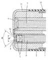
図1において、1は、内視鏡の挿入部可撓管の先端部分であり、その先端に連結された先端部本体2の先端面に、光像をとり入れる観察窓3と照明光を射出する照明窓4とが並んで配置されている。照明窓4には凹レンズが嵌め込まれている。
【0010】
観察窓3の内側には対物光学系5が配置され、その対物光学系5による被写体の投影位置にイメージガイドファイババンドル6の像入射面(又は固体撮像素子の撮像面)が配置されている。照明窓4の内側には、ライトガイドファイババンドル7の射出端が配置されている。
【0011】
10は、挿入部可撓管1に着脱自在に被覆される被覆シースであり、その先端部分には先端部本体2の先端面を被覆する例えばポリプロピレン又はポリエチレン等のような透明なプラスチックからなる透明カバー11が取り付けられており、観察窓3と照明窓4とが同じ透明カバー11により各々密着被覆された状態になっている。
【0012】
そのような透明カバー11は、全体として一定の厚みに形成されているが、観察窓3を被覆する部分の外表面12は凹レンズ状に形成されている。以下、その部分を凹レンズ部12という。
【0013】
このように構成された実施例の内視鏡の先端部においては、照明窓4から射出された照明光のうち大半の光は透明カバー11を透過して被写体に照射されるが、一部の光は透明カバー11の厚み内で反射を繰り返して観察窓3の方向に向かう。
【0014】
しかし、そのようにして透明カバー11の厚み内を通った光が観察窓3の近くに達し、透明カバー11に形成された凹レンズ部12において反射されると、光の進行方向が凹レンズ部12の内方に達しない方向に変換され、その光は観察窓3に達しない。
【0015】
また、照明窓4から射出された照明光のうち透明カバー11の厚み内で観察窓3以外の方向に向かってから周辺部等で反射されて観察窓3に向かう光があるが、図2に示されるように、上述の凹レンズ部12の反射作用はどの方向からの光に対しても全く同じように働くので、透明カバー11の厚み内を通ってどの方向からやって来た光も、進行方向が凹レンズ部12の内方に達しない方向に変換されて観察窓3に達しない。
【0016】
その結果、透明カバー11の内面反射に起因するフレアーやゴーストの発生がほとんど皆無になり、観察窓3を通してコントラストのよい良好な観察像を得ることができる。
【0017】
また、凹レンズ部12が観察窓3の外側に配置されていることにより、所定の観察視野角(空気中)θを得るための観察窓3部分における視野角θ′を狭くすることができるので、観察窓3から飛び込む不要光のうちフレアーやゴーストを発生させる光の範囲が狭くなる効果もある。
【0018】
【発明の効果】
本発明によれば、照明窓の表面と観察窓の表面とが同じ透明カバーで被覆された内視鏡の先端部において、透明カバーの観察窓に被覆された部分の外表面を凹レンズ状に形成したことにより、照明窓から射出されて透明カバーの厚み内で反射を繰り返して観察窓に向かってあらゆる方向からやって来る光が凹レンズ部の内方に入ってこないので、フレアーやゴーストのない良好な観察像を得ることができる。
【図面の簡単な説明】
【図1】本発明の実施例の内視鏡の先端部の側面断面図である。
【図2】本発明の実施例の内視鏡の先端部の、図1と異なる断面における部分断面図である。
【図3】従来の内視鏡の先端部の側面断面図である。
【符号の説明】
1 挿入部可撓管
2 先端部本体
3 観察窓
4 照明窓
5 対物光学系
10 被覆シース
11 透明カバー
12 凹レンズ部[0001]
TECHNICAL FIELD OF THE INVENTION
The present invention relates to a distal end portion of an endoscope, and particularly to a distal end portion of an endoscope in which an illumination window and an observation window provided at a distal end of an insertion portion are covered with the same transparent cover.
[0002]
[Prior art]
In recent years, there is an increasing need to reliably prevent infection from patient to patient via an endoscope.
[0003]
As a countermeasure, it is recommended to provide a detachable watertight sheath for the insertion section of the endoscope, use the endoscope covered with the sheath, and replace the sheath with a new one after use. This is one powerful means. In such a case, the sheath portion corresponding to the surfaces of the illumination window and the observation window must be formed transparent.
[0004]
However, when the surfaces of both windows are covered with one continuous transparent cover, for example, as shown in FIG. 3, the illumination light emitted from the
[0005]
Therefore, conventionally, a transparent cover is gradually formed, for example, from the illumination window side to the observation window side, and when the light emitted from the illumination window repeats reflection in the direction toward the observation window side in the thickness of the transparent cover, the reflection angle gradually decreases. So as not to reach the observation window (Japanese Patent No. 2868228).
[0006]
[Problems to be solved by the invention]
However, even if measures such as forming the transparent cover from the illumination window side to the observation window side gradually thinner are taken, of the illumination light emitted from the illumination window toward the direction other than the observation window, the peripheral portion of the transparent cover, etc. When the light is reflected at the observation window and reaches the observation window, the light enters the observation window and flares and ghosts occur in the observation field.
[0007]
Therefore, the present invention provides a tip of an endoscope that can obtain a good observation image without flare or ghost at the tip of the endoscope in which the surface of the illumination window and the surface of the observation window are covered with the same transparent cover. The purpose is to provide a department.
[0008]
[Means for Solving the Problems]
In order to achieve the above object, the distal end portion of the endoscope of the present invention is arranged such that an illumination window for emitting illumination light and an observation window for taking in a light image are arranged side by side at the distal end of the insertion portion, and the surface of the illumination window At the tip of the endoscope whose surface is covered with the same transparent cover, the outer surface of the transparent cover covered with the observation window is formed in a concave lens shape.
[0009]
BEST MODE FOR CARRYING OUT THE INVENTION
An embodiment of the present invention will be described with reference to the drawings.
In FIG. 1,
[0010]
An objective
[0011]
[0012]
Such a
[0013]
At the distal end portion of the endoscope according to the embodiment configured as described above, most of the illumination light emitted from the illumination window 4 passes through the
[0014]
However, when the light passing through the thickness of the
[0015]
In addition, of the illumination light emitted from the illumination window 4, there is light which is reflected in the peripheral portion and the like toward the
[0016]
As a result, almost no flare or ghost due to internal reflection of the
[0017]
In addition, since the
[0018]
【The invention's effect】
According to the present invention, at the tip of the endoscope in which the surface of the illumination window and the surface of the observation window are covered with the same transparent cover, the outer surface of the portion of the transparent cover covered with the observation window is formed in a concave lens shape. As a result, light emitted from the illumination window and reflected repeatedly within the thickness of the transparent cover and coming from all directions toward the observation window does not enter the inside of the concave lens part, so good observation without flare or ghost An image can be obtained.
[Brief description of the drawings]
FIG. 1 is a side sectional view of a distal end portion of an endoscope according to an embodiment of the present invention.
FIG. 2 is a partial cross-sectional view of a distal end portion of the endoscope according to the embodiment of the present invention in a cross section different from FIG.
FIG. 3 is a side sectional view of a distal end portion of a conventional endoscope.
[Explanation of symbols]
REFERENCE SIGNS
Claims (1)
Translated fromJapanese上記透明カバーの上記観察窓に被覆された部分の外表面を凹レンズ状に形成したことを特徴とする内視鏡の先端部。An illumination window for emitting illumination light and an observation window for taking in a light image are arranged side by side at the tip of the insertion section, and the surface of the illumination window and the surface of the observation window are covered with the same transparent cover. At the tip
A distal end portion of the endoscope, wherein an outer surface of a portion of the transparent cover covered with the observation window is formed in a concave lens shape.
Priority Applications (1)
| Application Number | Priority Date | Filing Date | Title |
|---|---|---|---|
| JP2002203414AJP4172959B2 (en) | 2002-07-12 | 2002-07-12 | End of the endoscope |
Applications Claiming Priority (1)
| Application Number | Priority Date | Filing Date | Title |
|---|---|---|---|
| JP2002203414AJP4172959B2 (en) | 2002-07-12 | 2002-07-12 | End of the endoscope |
Publications (2)
| Publication Number | Publication Date |
|---|---|
| JP2004041457Atrue JP2004041457A (en) | 2004-02-12 |
| JP4172959B2 JP4172959B2 (en) | 2008-10-29 |
Family
ID=31709285
Family Applications (1)
| Application Number | Title | Priority Date | Filing Date |
|---|---|---|---|
| JP2002203414AExpired - Fee RelatedJP4172959B2 (en) | 2002-07-12 | 2002-07-12 | End of the endoscope |
Country Status (1)
| Country | Link |
|---|---|
| JP (1) | JP4172959B2 (en) |
Cited By (1)
| Publication number | Priority date | Publication date | Assignee | Title |
|---|---|---|---|---|
| US11099374B2 (en) | 2017-06-29 | 2021-08-24 | Olympus Corporation | Endoscope |
- 2002
- 2002-07-12JPJP2002203414Apatent/JP4172959B2/ennot_activeExpired - Fee Related
Cited By (1)
| Publication number | Priority date | Publication date | Assignee | Title |
|---|---|---|---|---|
| US11099374B2 (en) | 2017-06-29 | 2021-08-24 | Olympus Corporation | Endoscope |
Also Published As
| Publication number | Publication date |
|---|---|
| JP4172959B2 (en) | 2008-10-29 |
Similar Documents
| Publication | Publication Date | Title |
|---|---|---|
| JP4777482B2 (en) | Endoscope | |
| JP3114298U (en) | Swallowable capsule for in vivo imaging | |
| JP4782900B2 (en) | Endoscope | |
| JP4668831B2 (en) | Endoscope | |
| US11311184B2 (en) | Tip part for a vision device | |
| JP5942046B2 (en) | Endoscope | |
| JPH04359218A (en) | Tip part of endoscope | |
| US8531513B2 (en) | Assembly method for endoscope image pickup unit and endoscope | |
| JP4130940B2 (en) | End of the endoscope | |
| WO2016121160A1 (en) | Endoscope | |
| JP2010194191A (en) | Endoscope and endoscope apparatus | |
| WO2014188787A1 (en) | Endoscope tip structure and endoscope | |
| JP2004049793A (en) | Endoscope tip | |
| JP2004041457A (en) | Distal end of endoscope | |
| JP4131008B2 (en) | End of the endoscope | |
| JPH105171A (en) | Endoscope protective cover | |
| JP4135877B2 (en) | End of the endoscope | |
| JP2004267255A (en) | Endoscope endoscope with mantle sheath | |
| JP4130941B2 (en) | End of the endoscope | |
| JP4071063B2 (en) | End of the endoscope | |
| JP2004073299A (en) | The tip of a pollution-proof endoscope | |
| EP3613328B1 (en) | A tip part for a vision device | |
| JPH0623811B2 (en) | End of endoscope | |
| JP4657013B2 (en) | End of the endoscope | |
| JP6671967B2 (en) | Endoscope |
Legal Events
| Date | Code | Title | Description |
|---|---|---|---|
| A621 | Written request for application examination | Free format text:JAPANESE INTERMEDIATE CODE: A621 Effective date:20050420 | |
| A977 | Report on retrieval | Free format text:JAPANESE INTERMEDIATE CODE: A971007 Effective date:20071214 | |
| A131 | Notification of reasons for refusal | Free format text:JAPANESE INTERMEDIATE CODE: A131 Effective date:20071220 | |
| A521 | Written amendment | Free format text:JAPANESE INTERMEDIATE CODE: A523 Effective date:20080201 | |
| A131 | Notification of reasons for refusal | Free format text:JAPANESE INTERMEDIATE CODE: A131 Effective date:20080410 | |
| A711 | Notification of change in applicant | Free format text:JAPANESE INTERMEDIATE CODE: A712 Effective date:20080430 | |
| A521 | Written amendment | Free format text:JAPANESE INTERMEDIATE CODE: A523 Effective date:20080522 | |
| TRDD | Decision of grant or rejection written | ||
| A01 | Written decision to grant a patent or to grant a registration (utility model) | Free format text:JAPANESE INTERMEDIATE CODE: A01 Effective date:20080731 | |
| A01 | Written decision to grant a patent or to grant a registration (utility model) | Free format text:JAPANESE INTERMEDIATE CODE: A01 | |
| A61 | First payment of annual fees (during grant procedure) | Free format text:JAPANESE INTERMEDIATE CODE: A61 Effective date:20080812 | |
| R150 | Certificate of patent or registration of utility model | Free format text:JAPANESE INTERMEDIATE CODE: R150 | |
| FPAY | Renewal fee payment (event date is renewal date of database) | Free format text:PAYMENT UNTIL: 20110822 Year of fee payment:3 | |
| LAPS | Cancellation because of no payment of annual fees |