JP2004041294A - Latch - Google Patents
LatchDownload PDFInfo
- Publication number
- JP2004041294A JP2004041294AJP2002199805AJP2002199805AJP2004041294AJP 2004041294 AJP2004041294 AJP 2004041294AJP 2002199805 AJP2002199805 AJP 2002199805AJP 2002199805 AJP2002199805 AJP 2002199805AJP 2004041294 AJP2004041294 AJP 2004041294A
- Authority
- JP
- Japan
- Prior art keywords
- contact surface
- locking means
- locking
- protrusion
- magnetic material
- Prior art date
- Legal status (The legal status is an assumption and is not a legal conclusion. Google has not performed a legal analysis and makes no representation as to the accuracy of the status listed.)
- Pending
Links
Images


Landscapes
- Purses, Travelling Bags, Baskets, Or Suitcases (AREA)
- Slide Fasteners, Snap Fasteners, And Hook Fasteners (AREA)
Abstract
Translated fromJapaneseDescription
Translated fromJapanese【0001】
【発明の属する技術分野】
本発明は、衣服やバッグなどに使用される係止具に関するものである。
【0002】
【従来の技術】
図8に示したような構成の所謂マグネットホックは、バッグの開閉止め具等として従来から広く用いられている。
【0003】
図8に示したマグネットホックは、鉄等の磁性材料によって形成される2つの金具1,2によって構成されており、金具1には磁性材料からなる突起部1aが形成され、金具2には突起部1aの挿入が可能な凹部2aが形成されている。
【0004】
金具2の内部には、図9(a)に示したように永久磁石3が配設されており、この永久磁石3の磁力によって金具1と金具2との係止状態が維持されるように構成されている。
【0005】
【発明が解決しようとする課題】
しかしながら、従来の所謂マグネットホックにおいては、金具2に金具1を装着しようとする際、金具1を金具2に近づけると、図9(b)に示したように、永久磁石3の磁力によって金具1の突起部1aが金具2の接触面2bに吸着してしまうことがある。一旦このような状態になると、金具2に吸着している金具1の位置を微妙に動かして突起部1aを凹部2aに挿入しなければならないために、幼い子供や手の不自由な身体障害者などには完全な装着状態にすることが困難になってしまうという問題があった。
【0006】
本発明の目的は、幼い子供や手の不自由な身体障害者でも容易に完全な装着状態にすることができる係止具を提供することにある。
【0007】
【課題を解決するための手段】
本発明によれば、第1に、第1の接触面を有し当該第1の接触面の中央部に突起部が形成された非磁性材料からなる第1の係止手段であって、前記第1の接触面の裏側の面には永久磁石が配設されている第1の係止手段と、該第1の係止手段の前記第1の接触面に当接する第2の接触面を有し、当該第2の接触面の中央部に前記突起部の挿入可能な挿入口が設けられた第2の係止手段であって、少なくともその一部分が磁性材料によって構成されている第2の係止手段とを具備することを特徴とする係止具を提供することができる。
【0008】
本発明によれば、第2に、第1の接触面を有し、少なくともその一部分が磁性材料によって構成されている本体部材と、該本体部材の前記第1の接触面の中央部に固定された非磁性材料からなる突起部を構成する突起部材とを有する第1の係止手段と、該第1の係止手段の前記第1の接触面に当接する第2の接触面を有し、当該第2の接触面の中央部に前記突起部の挿入可能な挿入口が設けられた第2の係止手段であって、少なくともその一部分が永久磁石によって構成されている第2の係止手段とを具備することを特徴とする係止具を提供することができる。
【0009】
【発明の実施の形態】
以下、図面を参照して本発明の実施形態について説明する。
【0010】
(実施形態1)
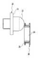
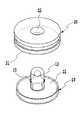
図1は、本発明の実施形態1の構成を示す斜視図であり、図1(a)は第1の係止具10と第2の係止具20とが分離している状態を示しており、図1(b)は第1の係止具10を第2の係止具20に装着した状態を示している。また、図2(a)は分離状態での断面図であり、図2(b)は装着状態での断面図である。
【0011】
図1および図2に示したように、装着時において係止具20に当接する係止具10の接触面11の中央部には突起部12が形成されており、係止具20の接触面21の中央部には突起部12の挿入が可能な挿入口22が形成されている。13は係止具10を衣服などに固定するための固定用部材である。
【0012】
図2に示したように、係止具10の接触面11の裏側の面には永久磁石30が配設されている。また、係止具20の接触面21の裏側の面には永久磁石40が配設されている。
【0013】
係止具20は、接触面21を有する部材23とこれと螺合する部材24との2体の部材によって構成されており、永久磁石40は、部材24の先端部と部材23との間に固定されている。また、係止具10の永久磁石30は、係止具10に螺合する雄ネジ14を有する固定用部材13と係止具10とによって挾持されている。
【0014】
ここで接触面11と突起部12とを有する係止具10は、真鍮や合成樹脂等の非磁性材料によって構成されている。
【0015】
また、本実施形態1においては、永久磁石40を具えた係止具20を構成する部材23,24の材料は、磁性材料、非磁性材料のどちらの材料でもよい。本実施形態1においては、係止具20の少なくとも一部分を、装着状態において永久磁石30の磁力により吸着可能な磁性材料で構成してあればよい。
【0016】
以上のように構成された本実施形態1においては、図3に示したように係止具10を係止具20に近接させて突起部12を係止具20に接触させたとしても、突起部12は係止具20に吸着しないため、係止具10または係止具20を動かして突起部12を挿入口22に容易に挿入することができて、簡単に図1(b)に示す装着状態にすることができる。
【0017】
また、本実施形態1においては、挿入口22が透孔となっているために、図1(b)に示した装着状態においては、挿入口(透孔)22を有する係止具20の外側から突起部12の先端部を視認することができるので、装着状態が完全であることを容易に確認することができる。
【0018】
なお、図1(b)および図2(b)に示したように、装着状態において突起部12が挿入口(透孔)22を貫通し、その先端部が係止具20の外側に露出するように突起部12の長さを選んでおけば、この露出した突起部12の先端部を押すことにより、係止具10を係止具20から容易に外すことができる。
【0019】
以上説明した実施形態1においては、永久磁石30,40の吸着力によって装着状態が維持されるものである。
【0020】
ここで、先に説明したように、係止具20の部材23または/および部材24を磁性材料によって構成した場合には、係止具20に永久磁石40を配設しなくてもよい。
【0021】
さらに、係止具20に永久磁石40を配設する構成とした場合には、図4に示したように、接触面11を有する磁性材料からなる本体部材10aと、接触面11の中央部に固定された非磁性材料からなる突起部を構成する突起部材10bとによって係止具10を構成してもよい。なお、本体部材10aはその全てを磁性材料で構成する必要はない。即ち、係止具20に永久磁石を配設する構成とした場合には、この永久磁石に吸着する磁性材料を少なくともその一部に含む本体部材と、非磁性材料からなる突起部材とによって係止具10を構成するようにしてもよい。
【0022】
(実施形態2)
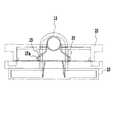
図5は本発明の実施形態2の構成を示す斜視図であり、図6(a)はその断面図である。また図6(b)は装着状態における断面図である。
【0023】
図5および図6(a),(b)において図1および図2(a),(b)と同一符号のものは同一のものを示している。
【0024】
ここで、本実施形態2においては、突起部12の側壁部に突出しているバネ材15が設けてあり、挿入口22の周壁部には、装着状態においてこのバネ材と嵌合する溝部25が形成されている。
【0025】
図7はバネ材15の構成を示す拡大図である。図7に示すように、このバネ材15は、屈折部15aを有する弾性的に変形可能なバネ材であり、屈折部15aが頂点となり、突起部12の長手方向に延在するように配設されている。
【0026】
このように構成された本実施形態2においては、装着状態においてバネ材15の屈折部15aが、溝部25に嵌合するので、装着時の係止力を実施形態1に比して強くすることができる。
【0027】
【発明の効果】
以上説明したように本発明によれば、幼い子供や手の不自由な身体障害者でも容易に完全な装着状態にすることができる。
【図面の簡単な説明】
【図1】本発明の実施形態1の構成を示す斜視図である。
【図2】本発明の実施形態1の構成を示す断面図である。
【図3】本発明の実施形態1の説明図である。
【図4】本発明の実施形態1の説明図である。
【図5】本発明の実施形態2の構成を示す斜視図である。
【図6】本発明の実施形態2の構成を示す断面図である。
【図7】本発明の実施形態2の説明図である。
【図8】従来の係止具の構成図である。
【図9】従来の係止具の説明図である。
【符号の説明】
10,20 係止具
10a 本体部材
10b 突起部材
11,12 接触面
12 突起部
13 固定用部材
14 雄ネジ
15 バネ材
15a 屈折部
22 挿入口
23,24 部材
25 溝部
30,40 永久磁石[0001]
TECHNICAL FIELD OF THE INVENTION
The present invention relates to a locking device used for clothes, bags, and the like.
[0002]
[Prior art]
A so-called magnet hook having a configuration as shown in FIG. 8 has been widely used as a stopper for opening and closing a bag.
[0003]
The magnet hook shown in FIG. 8 includes two
[0004]
As shown in FIG. 9A, a
[0005]
[Problems to be solved by the invention]
However, in a conventional so-called magnet hook, when the
[0006]
SUMMARY OF THE INVENTION It is an object of the present invention to provide a locking device that enables even a young child or a physically handicapped person to easily put the device in a completely worn state.
[0007]
[Means for Solving the Problems]
According to the present invention, first, there is provided a first locking means made of a non-magnetic material having a first contact surface and having a projection formed at a central portion of the first contact surface, A first locking means provided with a permanent magnet on a surface on the back side of the first contact surface, and a second contact surface abutting on the first contact surface of the first locking means. A second locking means provided with an insertion opening in which the protrusion can be inserted at a center portion of the second contact surface, at least a part of which is made of a magnetic material. And a locking device characterized by comprising locking means.
[0008]
According to the present invention, secondly, a main body member having a first contact surface, at least a part of which is made of a magnetic material, and fixed to a central portion of the first contact surface of the main body member A first locking means having a projection member forming a projection made of a non-magnetic material, and a second contact surface abutting on the first contact surface of the first locking means, A second locking means provided with an insertion opening through which the protrusion can be inserted at a central portion of the second contact surface, at least a part of which is constituted by a permanent magnet. And a locking tool characterized by comprising:
[0009]
BEST MODE FOR CARRYING OUT THE INVENTION
Hereinafter, embodiments of the present invention will be described with reference to the drawings.
[0010]
(Embodiment 1)
FIG. 1 is a perspective view showing the configuration of the first embodiment of the present invention, and FIG. 1A shows a state in which a
[0011]
As shown in FIG. 1 and FIG. 2, a
[0012]
As shown in FIG. 2, a
[0013]
The
[0014]
Here, the
[0015]
Further, in the first embodiment, the material of the
[0016]
In the first embodiment configured as described above, even if the
[0017]
Further, in the first embodiment, since the
[0018]
In addition, as shown in FIG. 1B and FIG. 2B, in the mounted state, the
[0019]
In the first embodiment described above, the mounted state is maintained by the attraction force of the
[0020]
Here, as described above, when the
[0021]
Further, in the case where the
[0022]
(Embodiment 2)
FIG. 5 is a perspective view showing the configuration of
[0023]
5 and FIGS. 6 (a) and 6 (b), the same reference numerals as those in FIGS. 1 and 2 (a) and 2 (b) denote the same components.
[0024]
Here, in the second embodiment, a
[0025]
FIG. 7 is an enlarged view showing the configuration of the
[0026]
In the second embodiment configured as described above, since the bending
[0027]
【The invention's effect】
As described above, according to the present invention, even a young child or a physically handicapped person can easily make a completely worn state.
[Brief description of the drawings]
FIG. 1 is a perspective view showing a configuration of a first embodiment of the present invention.
FIG. 2 is a cross-sectional view illustrating a configuration of
FIG. 3 is an explanatory diagram of
FIG. 4 is an explanatory diagram of
FIG. 5 is a perspective view illustrating a configuration of a second exemplary embodiment of the present invention.
FIG. 6 is a cross-sectional view illustrating a configuration of
FIG. 7 is an explanatory diagram of
FIG. 8 is a configuration diagram of a conventional locking device.
FIG. 9 is an explanatory view of a conventional locking device.
[Explanation of symbols]
10, 20
Claims (5)
Translated fromJapanese該第1の係止手段の前記第1の接触面に当接する第2の接触面を有し、当該第2の接触面の中央部に前記突起部の挿入可能な挿入口が設けられた第2の係止手段であって、少なくともその一部分が磁性材料によって構成されている第2の係止手段とを具備することを特徴とする係止具。A first locking means made of a non-magnetic material having a first contact surface and having a projection formed at a central portion of the first contact surface, the first engagement means being provided on a surface on the back side of the first contact surface. Is first locking means provided with a permanent magnet,
A second contact surface which comes into contact with the first contact surface of the first locking means, and an insertion port through which the protrusion can be inserted is provided at a central portion of the second contact surface; A locking tool, comprising: a second locking means, wherein at least a part of the second locking means is made of a magnetic material.
該第1の係止手段の前記第1の接触面に当接する第2の接触面を有し、当該第2の接触面の中央部に前記突起部の挿入可能な挿入口が設けられた第2の係止手段であって、少なくともその一部分が永久磁石によって構成されている第2の係止手段とを具備することを特徴とする係止具。A main body member having a first contact surface, at least a portion of which is made of a magnetic material, and a projection made of a non-magnetic material fixed to a central portion of the first contact surface of the main body member First locking means having a protruding member that performs
A second contact surface which comes into contact with the first contact surface of the first locking means, and an insertion port through which the protrusion can be inserted is provided at a central portion of the second contact surface; A second locking means, wherein at least a part of the locking means is constituted by a permanent magnet.
前記第1の係止手段の前記突起部を前記第2の係止手段の前記挿入口に挿入して、前記第1の接触面と前記第2の接触面とを当接させた装着状態において、前記バネ材の前記屈折部が嵌合可能な溝部が前記挿入口の周壁部に設けられていることを特徴とする請求項1または請求項2に記載の係止具。An elastically deformable spring material having a bent portion is provided on a side wall of the protrusion of the first locking means so as to extend in a longitudinal direction of the protrusion with the bent portion serving as an apex. And
In the mounting state in which the protrusion of the first locking means is inserted into the insertion opening of the second locking means, and the first contact surface and the second contact surface are in contact with each other. The locking device according to claim 1, wherein a groove portion into which the bending portion of the spring material can be fitted is provided on a peripheral wall portion of the insertion port.
Priority Applications (1)
| Application Number | Priority Date | Filing Date | Title |
|---|---|---|---|
| JP2002199805AJP2004041294A (en) | 2002-07-09 | 2002-07-09 | Latch |
Applications Claiming Priority (1)
| Application Number | Priority Date | Filing Date | Title |
|---|---|---|---|
| JP2002199805AJP2004041294A (en) | 2002-07-09 | 2002-07-09 | Latch |
Publications (1)
| Publication Number | Publication Date |
|---|---|
| JP2004041294Atrue JP2004041294A (en) | 2004-02-12 |
Family
ID=31706849
Family Applications (1)
| Application Number | Title | Priority Date | Filing Date |
|---|---|---|---|
| JP2002199805APendingJP2004041294A (en) | 2002-07-09 | 2002-07-09 | Latch |
Country Status (1)
| Country | Link |
|---|---|
| JP (1) | JP2004041294A (en) |
Cited By (3)
| Publication number | Priority date | Publication date | Assignee | Title |
|---|---|---|---|---|
| KR200476165Y1 (en) | 2013-07-24 | 2015-02-04 | 주식회사태진인터내셔날 | A bag with induced magnetic locking device |
| JP2017080508A (en)* | 2013-03-14 | 2017-05-18 | ザ ニールセン カンパニー (ユー エス) エルエルシー | System and method for collecting and analyzing EEG data |
| JP2022187820A (en)* | 2021-06-08 | 2022-12-20 | 株式会社Shiffon | school bag |
- 2002
- 2002-07-09JPJP2002199805Apatent/JP2004041294A/enactivePending
Cited By (4)
| Publication number | Priority date | Publication date | Assignee | Title |
|---|---|---|---|---|
| JP2017080508A (en)* | 2013-03-14 | 2017-05-18 | ザ ニールセン カンパニー (ユー エス) エルエルシー | System and method for collecting and analyzing EEG data |
| US11076807B2 (en) | 2013-03-14 | 2021-08-03 | Nielsen Consumer Llc | Methods and apparatus to gather and analyze electroencephalographic data |
| KR200476165Y1 (en) | 2013-07-24 | 2015-02-04 | 주식회사태진인터내셔날 | A bag with induced magnetic locking device |
| JP2022187820A (en)* | 2021-06-08 | 2022-12-20 | 株式会社Shiffon | school bag |
Similar Documents
| Publication | Publication Date | Title |
|---|---|---|
| EP1179307A2 (en) | Cord clip | |
| JPH04366289A (en) | Stopper | |
| JP2004041294A (en) | Latch | |
| US5506909A (en) | Noise filtering device | |
| JPS6118324B2 (en) | ||
| JP3993589B2 (en) | Magnetic clasps in jewelry | |
| JPH09289911A (en) | Interlocking tool for necklace or the like | |
| JPH11236780A (en) | Magnet assembly | |
| JPS63142617A (en) | Engaging tool | |
| JPH0542223Y2 (en) | ||
| JP2000325117A (en) | Necklace | |
| JPH0535697Y2 (en) | ||
| JPS61253808A (en) | Engaging structure of bag flap | |
| JP2529249Y2 (en) | Data line filter | |
| JP3000111U (en) | Attachment mechanism for jewelry | |
| JP2826758B2 (en) | Engaging tool | |
| JPH088112A (en) | Magnetic attracting fixture | |
| JPH0744169Y2 (en) | Fixing structure for mounting member of latch | |
| JPS5910215A (en) | Male unit for engagement device | |
| JPS62115807A (en) | Engagement device | |
| JPS62154702A (en) | Lock fitting for bag | |
| JPS61253806A (en) | Engaging structure of bag flap | |
| JPS62152404A (en) | Clamp jig for bags | |
| JPS62155810A (en) | Clasp for band | |
| JPS61146202A (en) | Crasp using permanent magnet |
Legal Events
| Date | Code | Title | Description |
|---|---|---|---|
| A621 | Written request for application examination | Free format text:JAPANESE INTERMEDIATE CODE: A621 Effective date:20050609 | |
| A977 | Report on retrieval | Free format text:JAPANESE INTERMEDIATE CODE: A971007 Effective date:20070219 | |
| A131 | Notification of reasons for refusal | Free format text:JAPANESE INTERMEDIATE CODE: A131 Effective date:20070227 | |
| A02 | Decision of refusal | Free format text:JAPANESE INTERMEDIATE CODE: A02 Effective date:20070626 |