JP2004040445A - Portable device having 3D display function, and 3D conversion program - Google Patents
Portable device having 3D display function, and 3D conversion programDownload PDFInfo
- Publication number
- JP2004040445A JP2004040445AJP2002194285AJP2002194285AJP2004040445AJP 2004040445 AJP2004040445 AJP 2004040445AJP 2002194285 AJP2002194285 AJP 2002194285AJP 2002194285 AJP2002194285 AJP 2002194285AJP 2004040445 AJP2004040445 AJP 2004040445A
- Authority
- JP
- Japan
- Prior art keywords
- image
- face
- display
- portable device
- display function
- Prior art date
- Legal status (The legal status is an assumption and is not a legal conclusion. Google has not performed a legal analysis and makes no representation as to the accuracy of the status listed.)
- Pending
Links
Images


Classifications
- H—ELECTRICITY
- H04—ELECTRIC COMMUNICATION TECHNIQUE
- H04N—PICTORIAL COMMUNICATION, e.g. TELEVISION
- H04N7/00—Television systems
- H04N7/14—Systems for two-way working
- G—PHYSICS
- G06—COMPUTING OR CALCULATING; COUNTING
- G06T—IMAGE DATA PROCESSING OR GENERATION, IN GENERAL
- G06T7/00—Image analysis
- G06T7/50—Depth or shape recovery
- G06T7/55—Depth or shape recovery from multiple images
- H—ELECTRICITY
- H04—ELECTRIC COMMUNICATION TECHNIQUE
- H04N—PICTORIAL COMMUNICATION, e.g. TELEVISION
- H04N13/00—Stereoscopic video systems; Multi-view video systems; Details thereof
- H04N13/30—Image reproducers
- H04N13/302—Image reproducers for viewing without the aid of special glasses, i.e. using autostereoscopic displays
- H04N13/31—Image reproducers for viewing without the aid of special glasses, i.e. using autostereoscopic displays using parallax barriers
- H—ELECTRICITY
- H04—ELECTRIC COMMUNICATION TECHNIQUE
- H04N—PICTORIAL COMMUNICATION, e.g. TELEVISION
- H04N13/00—Stereoscopic video systems; Multi-view video systems; Details thereof
- H04N13/30—Image reproducers
- H04N13/356—Image reproducers having separate monoscopic and stereoscopic modes
- H04N13/359—Switching between monoscopic and stereoscopic modes
- H—ELECTRICITY
- H04—ELECTRIC COMMUNICATION TECHNIQUE
- H04N—PICTORIAL COMMUNICATION, e.g. TELEVISION
- H04N13/00—Stereoscopic video systems; Multi-view video systems; Details thereof
- H04N13/30—Image reproducers
- H04N13/361—Reproducing mixed stereoscopic images; Reproducing mixed monoscopic and stereoscopic images, e.g. a stereoscopic image overlay window on a monoscopic image background
- H—ELECTRICITY
- H04—ELECTRIC COMMUNICATION TECHNIQUE
- H04N—PICTORIAL COMMUNICATION, e.g. TELEVISION
- H04N7/00—Television systems
- H04N7/14—Systems for two-way working
- H04N7/141—Systems for two-way working between two video terminals, e.g. videophone
- H04N7/142—Constructional details of the terminal equipment, e.g. arrangements of the camera and the display
- H04N2007/145—Handheld terminals
Landscapes
- Engineering & Computer Science (AREA)
- Multimedia (AREA)
- Signal Processing (AREA)
- Theoretical Computer Science (AREA)
- Physics & Mathematics (AREA)
- General Physics & Mathematics (AREA)
- Computer Vision & Pattern Recognition (AREA)
- Telephone Function (AREA)
- Controls And Circuits For Display Device (AREA)
- Testing, Inspecting, Measuring Of Stereoscopic Televisions And Televisions (AREA)
- Studio Devices (AREA)
- Processing Or Creating Images (AREA)
- Two-Way Televisions, Distribution Of Moving Picture Or The Like (AREA)
Abstract
Translated fromJapaneseDescription
Translated fromJapanese【0001】
【発明の属する技術分野】
本発明は、3D表示機能を備える携帯機器に関するものである。
【0002】
【従来の技術】
近年、携帯機器は小型化、高機能化が進み、携帯端末、携帯パソコン、携帯電話機等はカメラ機能が付加されている。例えば、カメラ付き携帯電話は最近普及し始め、撮影した画像を待ち受け画面に設定したり、撮影した画像をその場で通話相手に送信できるため便利である。
【0003】
又、特開平10−108152号公報には、高機能化の一環として、両眼視差を利用して3D表示させる携帯情報端末が開示されている。奥行き感のある立体画像を表示できるため、2次元画像に比べて臨場感、迫力感が増し、テレビ電話に応用される。この携帯情報端末は、2個のカメラを備えた腕に装着するタイプのものであり、2個のカメラで撮影された被写体の動きの水平方向成分に応じて時間差をつけた2枚の映像を生成し、それぞれを観察者の右目と左目に与えて3D表示を実現している。なお、3D表示とは視差を利用して立体表示することを意味している。
【0004】
【発明が解決しようとする課題】
しかしながら、上記従来の携帯情報端末は、2個のカメラを備えるため、高価格化、高消費電力化を招き不経済である。
【0005】
また、2個のカメラで撮影した画像を両眼視差を利用して3D表示するためには、2個のカメラを人の両眼の視差に相当する間隔だけ離して配置した状態で撮影することが望ましい。しかし、その間隔を保ちつつ他の構成部品を配置しようとすると、2個のカメラの配置による制約を受け、小型化、デザイン性が低下する。
【0006】
さらに、移動している被写体をカメラで撮った画像を3D表示画像とするのであるから、実質的には十分な画像とは言いがたい。しかも、カメラでは通常2D画像を撮影し、必要に応じて3D画像を撮影表示させるユーザにとっては、普段は2個のカメラのうちの1個しか使用しないことになる。
【0007】
従って、3D表示のために2個のカメラを設けることは、上述の高価格化、高消費電力化の問題や、小型化、デザイン性低下の問題を有しており、携帯情報端末における3D機能の実用化を困難にしていた。特に、携帯電話は小型、軽量、安価等の必要性があり、2個のカメラを設けることは困難である。
【0008】
【課題を解決するための手段】
本発明は、カメラ機能付き携帯端末例えばカメラ付き携帯電話機において、1個のカメラで撮影した通常の2D画像に対して、3D変換プログラムにより視差情報を付与して3D画像を作成して3D表示させる。視差情報の求め方は複数ある。例えば、携帯電話機で撮影する場合の平均距離に基づいて求めることができる。また、撮影した画像の明るさの強度に基づいて求めることができる。また、被写体に光を照射しその反射光の強度に基づいて求めることができる。また、ユーザの選択した被写体に対して選択しなかった残り画像と異なる視差を与えるように求めることができる。更に、予め得られている立体モデル情報を用いることにより、近似的に視差情報を得ることが出来る。
【0009】
上述の構成により、1個のカメラを備える携帯電話機で撮影した画像を、その場で簡単に3D表示することができる。しかも、携帯電話機は、ポケットサイズでいつも持ち歩いているため、例えば、空港で見送りに来てくれた人の別れ際の表情を撮影する場合など、とっさのシャッターチャンスにも素早く対応できる。
そして、逃さず撮影した自分のお気に入りの画像を迫力のある3D画像で楽しむことができる。
【0010】
3D画像を本格的に楽しむのではなく、たまに利用して楽しみたいと思っているユーザにとっても、いつも持ち歩く身近な携帯電話機で、自分が撮影したお気に入り画像を手軽に3D表示できるので、遊び感覚で楽しむこともできて実益がある。
【0011】
【発明の実施の形態】
<実施形態1>
本発明の実施の形態について、図1から図7に基づいて説明する。本発明は、任意の携帯機器に適用できるが、以下では、好適な実施形態として、折り畳み可能なカメラ付き携帯電話機について説明する。
【0012】
図1は、本実施形態に係る携帯電話機の要部構成を示すブロック図であり、図示しない基地局と通信する通信制御部101と、マイク102からの音声信号を符号化すると共に、通話相手の音声信号を復号する音声信号処理部103と、復号した音声信号を再生するスピーカ104と、プログラムを実行して携帯電話機全体を制御するプロセッサ105と、プロセッサ105により参照されるメモリ106と、ユーザの入力を受け付けるキー操作部107と、CCDカメラ等の一般的な2D画像撮影用のカメラモジュール108と、メイン画面用のカラー液晶モジュール109と、サブ画面用のカラー液晶モジュール110とが設けられている。
【0013】
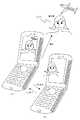
図2(A)は、折り畳み可能な携帯電話機201を開いた状態での内側(キー面)から見た外観を示しており、図2(B)は閉じた状態での外側(背面)から見た外観を示している。
【0014】
図2に示すように、スピーカ104は、携帯電話機の蓋部内側の上方中央に、マイク102は、本体部内側の下方中央にそれぞれ配されているため、開いた状態で通話がし易い。また、テンキーや十字キー209等からなる操作キー204は本体部内側に配され、メイン画面203は四角い形状で蓋部内側に配されており、開いた状態で操作性が良い。さらに、カメラ206は、蓋部外側のひんじ近くの中央付近に配され、サブ画面207は四角い形状で蓋部外側の中央付近に配されており、閉じた状態でもサブ画面207で被写体を確認しながら撮影ができる。また、背面キー208は、サブ画面207の下方に配され、閉じた状態でシャッタキーとして使用できる。このキー208は実施態様では1個であるが複数を併設し、サブ画面207に表示される情報を切り換える操作キー(例えばスクロールキー、蓄積中の3D画像の選択キー等)として使い分ける事が出来る。開いた状態で撮影する場合は、メイン画面203あるいはサブ画面207で被写体を確認しながら、操作キー201のいずれかのキーをシャッタキーとして利用して撮影する。
【0015】
メイン画面203は3D表示可能な液晶モジュールで構成されているが、メイン画面203とサブ画面207の両方または一方を3D表示可能な液晶モジュールにしてもよい。サブ画面207に待ち受け画面としてお気に入りの3D画像を表示させておくと、利用者は携帯電話機を開かなくても常に3D画像を見ることができるため付加価値が上がる。
【0016】
図3は、メイン画面203に使用する3D表示可能な液晶モジュールの要部構成の平面断面図を示しており、バックライト301と、偏光角の切替可能な切替用液晶素子302と、スリット状にパターン化したパターン化位相差板303と、TFT液晶304とが設けられている。
【0017】
3D画像を表示させる場合は、切替用液晶素子302の偏光角を切り替えることによりパターン化位相差板303との位相関係を変化させることにより、左目用画像がL画素306(図中において白画素で表示)を通過して右目に投影されないように遮断する(破線309)。右目用画像についても同様に、右目用画像がR画素305(図中において黒画素で表示)を通過して左目に投影されないように遮断する(破線310)。
【0018】
このように、観察者の右目には右目用画像だけが映し出され、また、左目には左目用画像だけが映し出されるため、観察者の右目と左目に異なる映像が与えられ、その結果、観察者は奥行き感のある3次元立体画像(3D画像)を知覚できる。
【0019】
また、2D画像(通常の2次元平面画像)を表示させる場合は、切替用液晶302とパターン化位相差板303による光の遮断を行わない。このように、切替用液晶302とパターン化位相差板303を電気的に制御することにより、2D画像と3D画像とを切り替えて表示することができる。2D画像と3D画像との切替操作は、例えば、操作キー204の任意のキー例えば電源キーを軽く押下して行えばよい。
【0020】
なお、本発明では、上記構成の液晶モジュールを用いているが、レンチキュラレンズを用いた構成やTFT液晶304の代りにCGシリコン液晶を用いた構成など他の構成でも構わない。また、上述の構成では、メイン画面203に3D表示可能な液晶モジュールを用いているが、メイン画面203に2D画像を表示させる通常の液晶モジュールを使用して、その表示を偏光メガネで観察する構成にしてもよい。その場合、2D画像を表示させる液晶モジュールと偏光メガネとを合わせた構成が3D表示可能な表示手段となる。
【0021】
次に、上述の構成の携帯電話機を用いて、カメラ206で撮影した2D画像から3D画像を作成してメイン画面203に表示するまでの処理手順について説明する。
【0022】
人の顔を撮影して3D表示する例について、図4に示すフローチャート、図5に示す表示画面例及び図6に示す視差情報を求める際の概念図に基づいて説明する。
【0023】
図5に示すように、カメラで写し出される被写体501の人の顔をメイン画面203で確認しながら、気に入った画像が表示されたときに操作キー204に割り当てられたシャッタキーを押下して被写体501を撮影して2D画像(静止画)として取り込む(S401)。
【0024】
次に、プロセッサ105により、取り込まれた2D画像から、目、鼻、口、眉、顎などの人の顔を構成する部品及び顔の輪郭を自動で抽出するか手動で抽出するかのモードが確認される(S402)。この顔画像抽出モードは、携帯電話機のメニュー画面等を利用して予めユーザによって設定してもよいし、操作の度にユーザが設定するようにしてもよい。顔画像抽出モードが手動の場合、ユーザは操作キー204を利用して上述の各顔部品の位置を指定し(S403)、その指定された位置情報に基づいて各顔部品の2次元座標が求められる(S404)。
このとき、不図示のペン入力やマウスやジョグダイヤルを利用して選択するようにしておくと操作性がさらによい。なお、顔の2D画像から3D画像を作成する場合、鼻が最も立体的に突出することになるので、自動抽出、手動抽出の何れであっても、部品として鼻は必須としておく。特に人間の感覚を考慮した場合、鼻の部分の突出を強調するようにすれば顔の立体感が得られる。
【0025】
一方、顔画像抽出モードが自動の場合は、エッジ検出などを利用した周知の顔部品抽出技術により各顔部品の2次元座標が求められる(S404)。携帯電話機のように、ユーザからの入力操作が不便な機器では、顔部品を自動で抽出できると都合がよい。また、撮影時に丸や四角の枠をメイン画面109に表示させておき、その枠付近に顔画像が位置するように撮影すると、顔部品を抽出する範囲が絞られるため、自動抽出の処理速度、精度が上がる。
【0026】
各顔部品の2次元座標が求まり顔画像が切り出されると、次に、特開2001−109907号公報に開示されている3次元モデル生成方法に基づき、人の顔の3次元モデルに各顔部品の座標が投影されて、顔画像全体についての3次元データが求まる(S405)。3次元モデルについては、人の顔の標準的な形状に基づいた標準顔形状モデルを利用すればよいが、丸顔、細顔などの複数種類の顔形状モデルを用意しておき、ユーザが選択するようにしてもよい。また、特定の人物について専用の顔形状モデルを予めメモリ106に記憶させておき、その人を撮影してその人専用の顔形状モデルを使用することにより、さらに精密な3D画像を作成することができる。例えば、携帯電話機の所有者本人の顔形状モデルをメモリ106に記憶させておけば、精密な自分の3D顔画像データを容易に作成できる。図2の携帯電話機を用いれば、蓋を閉じた状態でサブ画面207に自分の顔を確認しながら撮影できるため、自分の顔画像を撮影し易い。仲間同士で、それぞれが作成した自分の3D顔画像をメール添付等の手段でお互いに交換し合えば、精度の高い3D顔画像を複数人で楽しむことができる。なお、その人専用の顔形状モデルを算出するには計算量が大きいため、サーバで計算させた結果を携帯電話機にダウンロードする構成にしておいてもよい。
【0027】
顔画像の3次元データが求まると、次に、その3次元データに視差情報を付与する(S406)。ここでは、人の両目の標準的な間隔(例えば約6cm)と、携帯電話機で人の顔を撮影する場合の標準的な距離(例えば約1m)とに基づいて近似計算を行い、カメラ位置に仮に想定される人の両目と被写体の顔の3点で作られる顔の点を頂点とする角度αを求め、その角度αに相当する視差情報を3次元データに付与する。すなわち、図6に示すように、仮に想定される右目の位置から顔画像の3次元データに投影して変換されたデータを右目用画像データとし、同様に、仮に想定される左目の位置から顔画像の3次元データに投影して変換されたデータを左目用画像データとする。このようにして、右目用画像と左目用画像とを含む3D画像が作成される(S407)。
【0028】
作成された3D画像はメイン画面203に表示され、観察者の目には、図5に示すように人の顔がメイン画面に対して浮かび上がったように知覚される(S408)。なお、図5(B)では、図面作成技術の都合上、顔の鼻の高さや目の窪みなどの立体感が表現されていないが、観察者にはそれらの立体感が知覚され、迫力のある顔画像を楽しむことができる。また、図5(B)では、人の首や肩の辺りも図5(A)と同様に表示されている。このように顔以外の人の一部についても切り出すようにしてもよいし、着せ替え人形のように予めテンプレートとして用意しておいた服等を着せて表示するようにしてもよい。
【0029】
上述の例では、カメラ206から被写体501までの距離を予め所定の距離(例えば1m)として視差情報を算出しているが、撮影の度にユーザがその距離を操作キー204を介して入力するようにしてもよい。また、自分の顔を撮影する場合は、携帯電話機を持った方の手を伸ばして撮影する機会が多く、相手の人の顔を撮影する場合に比べて撮影距離が近いため(例えば50cm)、自分の顔を撮影する場合には自動的に所定距離を切り替えて視差情報を算出するようにしてもよい。なお、自分の顔を撮影しているか、相手の人の顔を撮影しているかは、例えば蓋の開閉を検出することにより自動的に判別できる。
【0030】
また、上述の例では、撮影した2D画像の中から人の顔を切り出して人の顔を3D表示させているが、人の顔以外の背景画像(図5の飛行機)を人の顔と共に表示してもよい。背景画像と共に表示すると、奥行き感がさらに増し迫力のある画像となる。
【0031】
また、上述の例では、人の顔の3次元モデルについて説明したが、例えば、ポメラニアンなどの犬の顔の3次元モデルを用意しておき、自分のペットの3D画像を作成してもよいし、人の体の3次元モデルを用意しておき、人の全身の3D画像を作成してもよい。
【0032】
また、上述の例では、被写体を撮影した後、図5(A)のように2D画像が表示されるが、予め操作キー204に3Dシャッターボタンを割り当てておき、上述の3D変換処理を全自動で行うようにしておけば、3Dシャッターボタンが押下された後、即座に図5(B)の3D画像を表示させることができて便利である。
<実施形態2>
アイオーデータ社製の「PLAY3DPC」製品キットを用いれば、デジタルカメラで撮影した画像をパソコンに取り込み、取り込んだ画像の各ブロックにおける明るさを専用ソフトで解析して、明るいブロックほど手前に位置するものと仮定して3D画像を作成することができる。そして、その作成した3D画像をパソコンに接続されたディスプレイに表示させ、ユーザは液晶メガネを介して3D画像を観察する。
【0033】
このように画像の明るさに基づいて3D画像を作成する技術を利用して、カメラ206で撮影した2D画像を複数のブロックに分割して各ブロックごとの明るさを検出し、明るいブロックほど手前に位置するように視差情報を各ブロックごとに付与して3D画像を作成し、メイン画面203に表示することができる。例えば、手前に自動車があり奥に建物があるような遠近感のある背景画像を表示することができる。
【0034】
この場合、2D画像の各ブロックの明るさの強度に応じて各ブロックごとに異なる視差情報を付与して3D画像を作成しているため、実施形態1で説明した視差情報を算出するための近似計算は必要ない。
<実施形態3>
特開2002−77944公報のように、光を被写体に照射し、その反射光の強度に基づいて被写体の各部までの距離を検出し、その距離情報に基づいて被写体の各部に対して異なる視差を付与して3D画像を作成し、外付けの立体映像表示装置で表示させる事が出来る。従って、カメラ206で撮影した2D画像の被写体までの距離に応じて被写体各部ごとに異なる視差情報を付与して3D画像を作成し、メイン画面203に表示することができる。この場合、図示しないが、被写体に対して光を照射する手段と、反射光の強度を検出するハード的な構成が必要である。
<実施形態4>
カメラ206で撮影され、メイン画面203に表示されている2D画像の中から、手前に位置する被写体をユーザが操作キー204(例えば、十字キー209)を介して選択し、その選択された被写体に対して残りの背景画像とは異なる視差情報を付与して3D画像を作成してもよい。
【0035】
例えば、図7(A)に示すように、ユーザは、メイン画面203に表示されている選択枠701を用いて、人の顔と飛行機を撮影した画像のうち手前に位置する人の顔を操作キー204(例えば十字キー209)を介して指定する。選択枠701の表示は丸でも四角でも構わない。また、大きさが可変の方が被写体を正確に指定しやすい。また、選択枠701で被写体を囲むのではなく、不図示のペン入力で切り出す被写体をなぞるようにして指定すると、より正確に被写体を切り出すことができる。
【0036】
次に、エッジ検出等の画像処理技術を利用して選択された被写体を切り出し、切り出された被写体の画像に対して、残りの背景画像よりも手前に見えるように視差を与えて3D画像を作成する。図7(A)の場合、髪の毛の一部や肩の辺りが選択枠701からはみ出ているが、選択枠701から多少はみ出た部分についてもエッジの連続性を推測しながら切り出すようにしてもよい。
【0037】
選択枠701付近の被写体画像が切り出され3D画像が作成されると、図7(B)に示すように、ユーザには顔が飛行機よりも浮き出たように知覚される。この場合、実施形態1の3次元モデルを使用していないため、鼻の高さなどの顔の立体感は表現されないが、3次元モデルに関する処理がないため、簡単に3D画像を作成できる。なお、この場合、被写体は人の顔に限らず建物などであってもよい。
【0038】
上述の例では、撮影後に選択枠701を用いて手前に見せたい被写体を選択するようにしているが、撮影時に選択枠701を表示させておき、手前の被写体を選択枠701付近に合わせた状態で撮影してもよい。そうすると、撮影後の選択枠701を指定する操作が必要なくなるので、シャッタキーを押すだけで一発で3D画像を表示することができる。
【0039】
また、上述の例では、被写体を1個だけ選択するようにしているが、手前の方に位置するものから順番に複数個を選択するようにしてもよい。その場合、複数個の各被写体ごとに異なる視差情報を付与する。このように、複数個の被写体を選択して3D表示すると奥行き感がさらに増して迫力がでる。
【0040】
上述の各実施形態における被写体撮影用のカメラ206は、いずれも通常の2D画像を撮影するためのカメラでよく、3D画像のための特別な機能は必要ない。したがって、3D画像撮影用のカメラをわざわざ用意する必要はなく、従来の携帯電話機に使用されているカメラをそのまま利用できるため都合がよい。
【0041】
また、上述の各実施形態において、2D画像から3D画像を作成するまでの処理の全部または一部はソフトウエアで処理される。この処理を行うための3D変換プログラムは予め携帯電話機に組み込まれていてもよいし、サーバからダウンロードする形態でもよい。また、この3D変換プログラムはパソコン等の他の機器で使用しても構わない。
【0042】
また、上述の各実施形態における処理の全部または一部を互いに組み合わせて処理してもよい。例えば、実施形態1の3次元モデルから3D画像を作成する処理と実施形態2の画像の明るさの強度に基づいて視差情報を求める処理を組み合わせると、迫力のある3D顔画像と共に遠近感のある背景画像を表示させることができる。
【0043】
なお、上記携帯電話機は折り畳み式のタイプのもので説明したが、ストレートタイプのものでも構わない。
【0044】
また、上記では、静止画を撮影する場合を例にして説明したが、動画を撮影するようにしても構わない。その場合は、動画を構成する複数の画像に対して静止画の場合と同様の処理を逐次行うようにすればよい。
<実施形態5>
カメラ206で撮影した自分の顔(2D静止画)を、3D画像にする場合、上記実施形態2では、パソコン側で処理している。しかしながら、2D画像を携帯電話本体内に設けた3D変換用専用ソフトを用いて即座に3D画像にすることも可能である。両眼用の画像を実写で撮ったものでない点で擬似的3D画像ではあるが、2D画像から3D画像とする市販のソフトを携帯電話に組み込むことで達成することが出来る。
<実施形態6>
上記実施形態はカメラで撮った画像を3Dとする場合であるが、通信手段により送信されてきた2D画像(写真、アニメ等)を撮影画像と同様に3D画像とし、3D表示することが出来る。その場合、操作キーの一つを3D画像作成指示キーとすれば良い。
【0045】
【発明の効果】
本発明によれば、携帯機器に設けたカメラで撮影した2D画像をその機器で3D表示することが出来る。
【0046】
また、本発明によればカメラ付き携帯電話機を用いて被写体を撮影し、その撮影した画像をその場で即座に3D表示することができる。携帯電話機はいつも持ち歩くものであるから、とっさのシャッターチャンスを逃すことなく画像を撮影して、その画像を3D表示できる。そして、2D表示に比べて迫力があるため、その画像を一層楽しむことができる。
【0047】
1個のカメラで済むため、携帯電話機の小型化、低消費電力化が可能である。また、2個のカメラを用いる場合に比べて、部品配置のための設計の自由度が格段に向上する。
【図面の簡単な説明】
【図1】本発明の実施形態を示すものであり、携帯電話機の要部構成を示すブロック図である。
【図2】折り畳み可能な携帯電話機を開いた状態でのキー面を示す正面図(A)と閉じた状態での背面を示す正面図(B)である。
【図3】3D表示可能な液晶ディスプレイの要部構成を示す断面図である。
【図4】実施形態1において、撮影した顔写真から3D画像を作成する際の動作を示すフローチャートである。
【図5】実施形態1において、撮影した顔写真から3D画像を作成する際の表示画面例である。
【図6】実施形態1における視差情報の求め方を説明するための概念図である。
【図7】実施形態4において、撮影した顔写真から3D画像を作成する際の表示画面例である。
【符号の説明】
102 マイク
104 スピーカ
108 カメラモジュール
109 メイン画面
110 サブ画面
201 操作キー
202 背面キー
206 カメラ[0001]
TECHNICAL FIELD OF THE INVENTION
The present invention relates to a portable device having a 3D display function.
[0002]
[Prior art]
2. Description of the Related Art In recent years, portable devices have become smaller and more sophisticated, and portable terminals, portable personal computers, portable telephones, and the like have a camera function. For example, camera-equipped mobile phones have recently become widespread, and are convenient because a captured image can be set as a standby screen or the captured image can be transmitted to a call partner on the spot.
[0003]
Further, Japanese Patent Application Laid-Open No. 10-108152 discloses a portable information terminal that displays 3D images using binocular parallax as a part of higher functionality. Since a stereoscopic image with a sense of depth can be displayed, a sense of presence and a sense of power are increased as compared with a two-dimensional image. This portable information terminal is of a type to be worn on an arm having two cameras, and is capable of displaying two images with a time difference according to the horizontal component of the movement of a subject captured by the two cameras. The 3D display is realized by giving the images to the right and left eyes of the observer. In addition, 3D display means performing stereoscopic display using parallax.
[0004]
[Problems to be solved by the invention]
However, since the above-mentioned conventional portable information terminal includes two cameras, it is expensive and high power consumption, which is uneconomical.
[0005]
In addition, in order to display images taken by two cameras in 3D using binocular parallax, it is necessary to take images with the two cameras separated by an interval corresponding to the parallax of human eyes. Is desirable. However, if an attempt is made to arrange other components while maintaining the distance, the arrangement of the two cameras is restricted, resulting in a reduction in size and design.
[0006]
Furthermore, since an image of a moving subject taken by a camera is used as a 3D display image, it cannot be said that the image is substantially sufficient. In addition, a user who normally shoots a 2D image with a camera and shoots and displays a 3D image as necessary usually uses only one of the two cameras.
[0007]
Therefore, providing two cameras for 3D display has the above-described problems of high price, high power consumption, miniaturization, and degraded design. Was difficult to put into practical use. In particular, mobile phones need to be small, light, inexpensive, and so on, and it is difficult to provide two cameras.
[0008]
[Means for Solving the Problems]
According to the present invention, in a mobile terminal with a camera function, for example, a mobile phone with a camera, parallax information is added to a normal 2D image captured by one camera by using a 3D conversion program to create a 3D image and display the 3D image. . There are a plurality of methods for obtaining parallax information. For example, it can be obtained based on the average distance when shooting with a mobile phone. Further, it can be obtained based on the intensity of the brightness of the captured image. Further, it can be obtained based on the intensity of the reflected light by irradiating the subject with light. In addition, it is possible to request that a parallax different from the remaining image not selected is given to the subject selected by the user. Furthermore, disparity information can be approximately obtained by using previously obtained stereo model information.
[0009]
With the above configuration, an image captured by a mobile phone having one camera can be easily displayed in 3D on the spot. Moreover, since the mobile phone is always carried around in a pocket size, it can quickly respond to a sudden photo opportunity, for example, when photographing a parting expression of a person who came off at the airport.
Then, the user can enjoy his favorite image taken without missing as a powerful 3D image.
[0010]
Even users who want to enjoy 3D images occasionally instead of enjoying them in earnest can easily display their favorite images in 3D with a mobile phone that they always carry around. You can enjoy it and it will be profitable.
[0011]
BEST MODE FOR CARRYING OUT THE INVENTION
<First embodiment>
An embodiment of the present invention will be described with reference to FIGS. Although the present invention can be applied to any portable device, a foldable camera-equipped mobile phone will be described below as a preferred embodiment.
[0012]
FIG. 1 is a block diagram showing a main configuration of a mobile phone according to the present embodiment. The communication control unit 101 communicates with a base station (not shown). An audio
[0013]
2A shows the appearance of the foldable mobile phone 201 when viewed from the inside (key surface) in an open state, and FIG. 2B shows the appearance when viewed from the outside (rear surface) in a closed state. The appearance is shown.
[0014]
As shown in FIG. 2, the
[0015]
Although the main screen 203 is composed of a liquid crystal module capable of 3D display, a liquid crystal module capable of 3D display on both or one of the main screen 203 and the sub screen 207 may be used. If a favorite 3D image is displayed as a standby screen on the sub-screen 207, the user can always view the 3D image without opening the mobile phone, thereby increasing the added value.
[0016]
FIG. 3 is a plan cross-sectional view of a main part configuration of a liquid crystal module capable of 3D display used for the main screen 203, and includes a backlight 301, a switching liquid crystal element 302 capable of switching a polarization angle, and a slit shape. A patterned retardation plate 303 having a pattern and a TFT liquid crystal 304 are provided.
[0017]
In the case of displaying a 3D image, the left eye image is changed to the L pixel 306 (white pixel in the figure) by changing the phase relationship with the patterned retardation plate 303 by switching the polarization angle of the switching liquid crystal element 302. (Indicated by a broken line 309). Similarly, the right-eye image is blocked so that the right-eye image does not pass through the R pixel 305 (shown as a black pixel in the figure) and is projected onto the left eye (broken line 310).
[0018]
As described above, since only the image for the right eye is projected on the right eye of the observer and only the image for the left eye is projected on the left eye, different images are given to the right and left eyes of the observer. Can perceive a three-dimensional stereoscopic image (3D image) with a sense of depth.
[0019]
When displaying a 2D image (a normal two-dimensional planar image), the switching liquid crystal 302 and the patterned retardation plate 303 do not block light. As described above, by electrically controlling the switching liquid crystal 302 and the patterned retardation plate 303, a 2D image and a 3D image can be switched and displayed. The switching operation between the 2D image and the 3D image may be performed by, for example, lightly pressing an arbitrary key of the operation keys 204, for example, a power key.
[0020]
In the present invention, the liquid crystal module having the above configuration is used. However, other configurations such as a configuration using a lenticular lens or a configuration using a CG silicon liquid crystal instead of the TFT liquid crystal 304 may be used. In the above configuration, a liquid crystal module capable of 3D display is used on the main screen 203, but a normal liquid crystal module for displaying a 2D image on the main screen 203 is used, and the display is observed with polarized glasses. It may be. In this case, a combination of a liquid crystal module for displaying a 2D image and polarized glasses is a display unit capable of 3D display.
[0021]
Next, a processing procedure from creating a 3D image from a 2D image captured by the camera 206 to displaying the 3D image on the main screen 203 using the mobile phone having the above configuration will be described.
[0022]
An example in which a person's face is photographed and displayed in 3D will be described based on a flowchart shown in FIG. 4, a display screen example shown in FIG. 5, and a conceptual diagram for obtaining disparity information shown in FIG.
[0023]
As shown in FIG. 5, while checking the face of the person of the subject 501 projected by the camera on the main screen 203, when a favorite image is displayed, the shutter key assigned to the operation key 204 is pressed and the subject 501 is pressed. Is captured and captured as a 2D image (still image) (S401).
[0024]
Next, the
At this time, operability is further improved by making selections using a pen input (not shown), a mouse or a jog dial. When a 3D image is created from a 2D image of a face, the nose protrudes most three-dimensionally. Therefore, the nose is indispensable as a part in either automatic extraction or manual extraction. In particular, when human sensation is considered, a three-dimensional appearance of the face can be obtained by emphasizing the protrusion of the nose.
[0025]
On the other hand, when the face image extraction mode is automatic, two-dimensional coordinates of each face part are obtained by a well-known face part extraction technique using edge detection or the like (S404). It is convenient for a device such as a mobile phone in which an input operation from a user is inconvenient to automatically extract face parts. In addition, when a round or square frame is displayed on the
[0026]
When the two-dimensional coordinates of each face part are determined and the face image is cut out, each face part is then converted into a three-dimensional model of a human face based on the three-dimensional model generation method disclosed in Japanese Patent Application Laid-Open No. 2001-109907. Are projected to obtain three-dimensional data for the entire face image (S405). For the three-dimensional model, a standard face shape model based on a standard shape of a human face may be used, but a plurality of types of face shape models such as a round face and a thin face are prepared, and the user selects the face shape model. You may make it. In addition, a dedicated face shape model for a specific person is stored in the
[0027]
When the three-dimensional data of the face image is obtained, disparity information is added to the three-dimensional data (S406). Here, an approximate calculation is performed based on a standard distance (for example, about 6 cm) between both eyes of a person and a standard distance (for example, about 1 m) when photographing a person's face with a mobile phone, and the camera position is determined. An angle α having a vertex at a point of a face formed by the supposed human eyes and the face of the subject is obtained, and disparity information corresponding to the angle α is added to the three-dimensional data. That is, as shown in FIG. 6, the data obtained by projecting the tentatively assumed right-eye position onto the three-dimensional data of the face image is used as the right-eye image data. The data projected and converted to the three-dimensional data of the image is defined as left-eye image data. In this way, a 3D image including the right-eye image and the left-eye image is created (S407).
[0028]
The created 3D image is displayed on the main screen 203, and the observer perceives the face of the person as rising to the main screen as shown in FIG. 5 (S408). In FIG. 5B, the three-dimensional effect such as the height of the nose of the face and the depression of the eyes is not represented due to the drawing creation technique, but the observer perceives the three-dimensional effect, and the force is powerful. You can enjoy a certain face image. In FIG. 5B, the area around the neck and shoulder of the person is also displayed in the same manner as in FIG. 5A. In this way, a part of a person other than the face may be cut out, or clothes and the like prepared in advance as a template, such as a dress-up doll, may be displayed.
[0029]
In the above-described example, the parallax information is calculated in advance by setting the distance from the camera 206 to the subject 501 to a predetermined distance (for example, 1 m), but the user inputs the distance via the operation keys 204 each time shooting is performed. It may be. In addition, when taking a picture of one's own face, there are many opportunities to reach the hand holding the mobile phone and take a picture, and the photographing distance is shorter than when photographing the face of the other person (for example, 50 cm). When photographing one's own face, parallax information may be calculated by automatically switching a predetermined distance. It should be noted that whether a person's face is being photographed or a person's face is being photographed can be automatically determined by, for example, detecting whether the lid is open or closed.
[0030]
In the above example, the human face is cut out from the captured 2D image and the human face is displayed in 3D. However, a background image (the airplane in FIG. 5) other than the human face is displayed together with the human face. May be. When displayed together with the background image, a sense of depth is further increased, resulting in a powerful image.
[0031]
In the above example, a three-dimensional model of a human face has been described. However, for example, a three-dimensional model of a dog's face such as a pomeranian may be prepared, and a 3D image of its own pet may be created. Alternatively, a three-dimensional model of a human body may be prepared, and a 3D image of the whole human body may be created.
[0032]
In addition, in the above-described example, a 2D image is displayed as shown in FIG. 5A after the subject is photographed. However, a 3D shutter button is assigned to the operation keys 204 in advance, and the above-described 3D conversion processing is automatically performed. 5B, the 3D image of FIG. 5B can be displayed immediately after the 3D shutter button is pressed, which is convenient.
<
By using IODATA's "PLAY3DPC" product kit, images taken with a digital camera can be imported to a personal computer, and the brightness of each block of the acquired image can be analyzed with dedicated software. And a 3D image can be created. Then, the created 3D image is displayed on a display connected to a personal computer, and the user observes the 3D image through liquid crystal glasses.
[0033]
By utilizing the technique of creating a 3D image based on the brightness of the image, the 2D image captured by the camera 206 is divided into a plurality of blocks, and the brightness of each block is detected. The 3D image can be created by adding parallax information to each block so that the 3D image is located in the main screen 203. For example, it is possible to display a background image with a perspective such as a car in front and a building in the back.
[0034]
In this case, since different parallax information is given to each block according to the intensity of brightness of each block of the 2D image to create a 3D image, the approximation for calculating the parallax information described in the first embodiment is performed. No calculations are required.
<Embodiment 3>
As disclosed in Japanese Patent Application Laid-Open No. 2002-77944, light is irradiated onto a subject, a distance to each part of the subject is detected based on the intensity of the reflected light, and a different parallax is obtained for each part of the subject based on the distance information. The 3D image can be created by adding the 3D image and displayed on an external stereoscopic image display device. Therefore, a different 3D image can be created by adding different parallax information to each part of the subject according to the distance to the subject of the 2D image captured by the camera 206 and displayed on the main screen 203. In this case, although not shown, a means for irradiating the subject with light and a hardware configuration for detecting the intensity of the reflected light are required.
<Embodiment 4>
The user selects a subject located on the near side from the 2D image captured by the camera 206 and displayed on the main screen 203 via the operation keys 204 (for example, the cross key 209), and assigns the selected subject to the selected subject. On the other hand, a 3D image may be created by adding disparity information different from the remaining background image.
[0035]
For example, as shown in FIG. 7A, the user operates a human face and a human face located in the front of an image of an airplane by using a selection frame 701 displayed on the main screen 203. It is designated via the key 204 (for example, the cross key 209). The display of the selection frame 701 may be a circle or a square. A variable size makes it easier to specify a subject accurately. In addition, if the object to be cut out is specified by tracing the object to be cut out with a pen input (not shown) instead of surrounding the object with the selection frame 701, the object can be cut out more accurately.
[0036]
Next, a selected subject is cut out using an image processing technique such as edge detection, and a 3D image is created by giving parallax to the cut-out subject image so that it can be seen closer to the front than the remaining background image. I do. In the case of FIG. 7A, a part of the hair and the vicinity of the shoulder protrude from the selection frame 701, but a part of the hair slightly protruding from the selection frame 701 may be cut out while estimating the continuity of the edge. .
[0037]
When the subject image near the selection frame 701 is cut out to create a 3D image, as shown in FIG. 7B, the user perceives that the face has risen more than the airplane. In this case, since the three-dimensional model of the first embodiment is not used, the three-dimensional appearance of the face such as the height of the nose is not expressed, but since there is no processing related to the three-dimensional model, a 3D image can be easily created. In this case, the subject is not limited to a human face, but may be a building or the like.
[0038]
In the above-described example, the subject to be shown to the front is selected using the selection frame 701 after shooting. However, the selection frame 701 is displayed at the time of shooting, and the subject in front is set near the selection frame 701. You may shoot with. Then, since the operation of designating the selection frame 701 after photographing is not required, a 3D image can be displayed by one shot only by pressing the shutter key.
[0039]
Further, in the above example, only one subject is selected, but a plurality of subjects may be selected in order from the one located nearer. In that case, different parallax information is assigned to each of the plurality of subjects. As described above, when a plurality of subjects are selected and displayed in 3D, the sense of depth is further increased and the force is increased.
[0040]
The camera 206 for capturing an object in each of the above-described embodiments may be a camera for capturing a normal 2D image, and does not require a special function for a 3D image. Therefore, there is no need to prepare a camera for capturing 3D images, and the camera used for a conventional mobile phone can be used as it is, which is convenient.
[0041]
In each of the above-described embodiments, all or a part of the processing up to creation of a 3D image from a 2D image is processed by software. The 3D conversion program for performing this processing may be incorporated in the mobile phone in advance, or may be downloaded from a server. Further, the 3D conversion program may be used by another device such as a personal computer.
[0042]
Further, all or a part of the processes in the above-described embodiments may be combined with each other and performed. For example, when the process of creating a 3D image from the three-dimensional model of the first embodiment and the process of obtaining parallax information based on the brightness intensity of the image of the second embodiment are combined, a powerful 3D face image and a perspective are provided. A background image can be displayed.
[0043]
Although the above-described mobile phone has been described as a foldable type, it may be a straight type.
[0044]
In the above description, a case where a still image is shot has been described as an example, but a moving image may be shot. In that case, the same processing as in the case of a still image may be sequentially performed on a plurality of images constituting a moving image.
<
In the case of converting a face (2D still image) taken by the camera 206 into a 3D image, in the second embodiment, processing is performed on the personal computer side. However, it is also possible to immediately convert the 2D image into a 3D image using dedicated software for 3D conversion provided in the mobile phone body. Although it is a pseudo 3D image in that the image for both eyes is not actually photographed, it can be achieved by incorporating commercially available software for converting a 2D image into a 3D image into a mobile phone.
<Embodiment 6>
In the above embodiment, the image taken by the camera is 3D, but the 2D image (photograph, animation, etc.) transmitted by the communication means can be converted into a 3D image in the same manner as the photographed image and displayed in 3D. In that case, one of the operation keys may be a 3D image creation instruction key.
[0045]
【The invention's effect】
ADVANTAGE OF THE INVENTION According to this invention, the 2D image image | photographed with the camera provided in the portable apparatus can be displayed on the apparatus by 3D.
[0046]
Further, according to the present invention, a subject can be photographed using a camera-equipped mobile phone, and the photographed image can be immediately displayed in 3D on the spot. Since a mobile phone is always carried around, it is possible to capture an image without missing a photo opportunity and display the image in 3D. And since it is powerful compared with 2D display, the image can be enjoyed further.
[0047]
Since only one camera is required, the size and power consumption of the mobile phone can be reduced. In addition, the degree of freedom of design for component placement is significantly improved as compared with the case where two cameras are used.
[Brief description of the drawings]
FIG. 1 illustrates an embodiment of the present invention, and is a block diagram illustrating a main configuration of a mobile phone.
FIG. 2A is a front view showing a key surface when a foldable mobile phone is opened, and FIG. 2B is a front view showing a back surface when the foldable mobile phone is closed.
FIG. 3 is a cross-sectional view illustrating a configuration of a main part of a liquid crystal display capable of 3D display.
FIG. 4 is a flowchart illustrating an operation when creating a 3D image from a photographed face photograph in the first embodiment.
FIG. 5 is an example of a display screen when a 3D image is created from a photographed face photograph in the first embodiment.
FIG. 6 is a conceptual diagram illustrating how to obtain disparity information according to the first embodiment.
FIG. 7 is an example of a display screen when a 3D image is created from a photographed face photograph in the fourth embodiment.
[Explanation of symbols]
102
Claims (7)
Translated fromJapanese上記撮影手段で撮影された画像に視差情報を付与して3D画像を作成する手段と、
作成された3D画像を表示可能な表示手段と、を備えることを特徴とする3D表示機能を備える携帯機器。Shooting means,
Means for creating a 3D image by adding parallax information to the image captured by the image capturing means;
A portable device having a 3D display function, comprising: display means capable of displaying the created 3D image.
上記撮影手段で撮影された画像に視差情報を付与して3D画像を作成する手段と、
作成された3D画像を表示可能な表示手段と、を備えることを特徴とする3D表示機能を備える携帯機器。One photography means,
Means for creating a 3D image by adding parallax information to the image captured by the image capturing means;
A portable device having a 3D display function, comprising: display means capable of displaying the created 3D image.
選択された被写体画像に対して、残りの画像とは異なる視差情報を付与することを特徴とする請求項2に記載の3D表示機能を備える携帯機器。Means for selecting a specific subject from the captured images,
The portable device having a 3D display function according to claim 2, wherein disparity information different from that of the remaining images is added to the selected subject image.
入力された2D画像から人の顔画像を切り出すステップと、
切り出された顔画像に対して視差情報を付与して3D画像を作成するステップと、
作成された3D画像を出力するステップと、をコンピュータに実行させるための3D変換プログラム。Inputting a 2D image;
Cutting out a human face image from the input 2D image;
Adding parallax information to the cut-out face image to create a 3D image;
And a step of outputting the created 3D image.
Priority Applications (5)
| Application Number | Priority Date | Filing Date | Title |
|---|---|---|---|
| JP2002194285AJP2004040445A (en) | 2002-07-03 | 2002-07-03 | Portable device having 3D display function, and 3D conversion program |
| EP03014861AEP1379063A1 (en) | 2002-07-03 | 2003-06-30 | Mobile device for capturing, generating and displaying three-dimensional images using a single camera |
| KR1020030044629AKR20040004135A (en) | 2002-07-03 | 2003-07-02 | Mobile equipment with three dimensional display function |
| CNB031453090ACN100469152C (en) | 2002-07-03 | 2003-07-03 | Portable device with 3D display function |
| US10/611,871US7889192B2 (en) | 2002-07-03 | 2003-07-03 | Mobile equipment with three dimensional display function |
Applications Claiming Priority (1)
| Application Number | Priority Date | Filing Date | Title |
|---|---|---|---|
| JP2002194285AJP2004040445A (en) | 2002-07-03 | 2002-07-03 | Portable device having 3D display function, and 3D conversion program |
Publications (1)
| Publication Number | Publication Date |
|---|---|
| JP2004040445Atrue JP2004040445A (en) | 2004-02-05 |
Family
ID=29720268
Family Applications (1)
| Application Number | Title | Priority Date | Filing Date |
|---|---|---|---|
| JP2002194285APendingJP2004040445A (en) | 2002-07-03 | 2002-07-03 | Portable device having 3D display function, and 3D conversion program |
Country Status (5)
| Country | Link |
|---|---|
| US (1) | US7889192B2 (en) |
| EP (1) | EP1379063A1 (en) |
| JP (1) | JP2004040445A (en) |
| KR (1) | KR20040004135A (en) |
| CN (1) | CN100469152C (en) |
Cited By (14)
| Publication number | Priority date | Publication date | Assignee | Title |
|---|---|---|---|---|
| JP2009129420A (en)* | 2007-11-28 | 2009-06-11 | Fujifilm Corp | Image processing apparatus and method, and program |
| JP2009545929A (en)* | 2006-08-01 | 2009-12-24 | クゥアルコム・インコーポレイテッド | Real-time acquisition and generation of stereoscopic images and videos on planar low power mobile devices |
| JP2010507822A (en)* | 2006-10-26 | 2010-03-11 | シーリアル テクノロジーズ ソシエテ アノニム | Content generation system |
| JP2010056836A (en)* | 2008-08-28 | 2010-03-11 | Fujifilm Corp | Three-dimensional display device and method and program |
| JP2010193458A (en)* | 2009-02-19 | 2010-09-02 | Sony Europe Ltd | Image processing device, image processing system, and image processing method |
| JP2011087100A (en)* | 2009-10-15 | 2011-04-28 | Jvc Kenwood Holdings Inc | Pseudo-stereoscopic image generation device and pseudo-stereoscopic image display system |
| US8106939B2 (en) | 2005-11-02 | 2012-01-31 | Sony Corporation | Image processing method, image processing device and image display apparatus employing the image processing device |
| JP2013051617A (en)* | 2011-08-31 | 2013-03-14 | Toshiba Corp | Object search device, video display device and object search method |
| US8416276B2 (en) | 2006-10-26 | 2013-04-09 | Seereal Technologies S.A. | Mobile telephony system comprising holographic display |
| JP2014504074A (en)* | 2011-01-23 | 2014-02-13 | エクストリーム リアリティー エルティーディー. | Method, system, apparatus and associated processing logic for generating stereoscopic 3D images and video |
| JP2014508430A (en)* | 2010-12-01 | 2014-04-03 | クゥアルコム・インコーポレイテッド | Zero parallax plane for feedback-based 3D video |
| JP2014209247A (en)* | 2006-10-26 | 2014-11-06 | シーリアル テクノロジーズソシエテ アノニムSeereal Technologies S.A. | 3d content generation system, method thereof and communication method |
| US8902290B2 (en) | 2011-01-19 | 2014-12-02 | Renesas Electronics Corporation | Portable apparatus and microcomputer |
| US9014462B2 (en) | 2010-11-10 | 2015-04-21 | Panasonic Intellectual Property Management Co., Ltd. | Depth information generating device, depth information generating method, and stereo image converter |
Families Citing this family (96)
| Publication number | Priority date | Publication date | Assignee | Title |
|---|---|---|---|---|
| US8396328B2 (en) | 2001-05-04 | 2013-03-12 | Legend3D, Inc. | Minimal artifact image sequence depth enhancement system and method |
| US7907793B1 (en) | 2001-05-04 | 2011-03-15 | Legend Films Inc. | Image sequence depth enhancement system and method |
| US20050231505A1 (en)* | 1998-05-27 | 2005-10-20 | Kaye Michael C | Method for creating artifact free three-dimensional images converted from two-dimensional images |
| US7116324B2 (en)* | 1998-05-27 | 2006-10-03 | In-Three, Inc. | Method for minimizing visual artifacts converting two-dimensional motion pictures into three-dimensional motion pictures |
| US7260369B2 (en)* | 2005-08-03 | 2007-08-21 | Kamilo Feher | Location finder, tracker, communication and remote control system |
| US8897596B1 (en) | 2001-05-04 | 2014-11-25 | Legend3D, Inc. | System and method for rapid image sequence depth enhancement with translucent elements |
| US8401336B2 (en) | 2001-05-04 | 2013-03-19 | Legend3D, Inc. | System and method for rapid image sequence depth enhancement with augmented computer-generated elements |
| US9286941B2 (en) | 2001-05-04 | 2016-03-15 | Legend3D, Inc. | Image sequence enhancement and motion picture project management system |
| US7107081B1 (en) | 2001-10-18 | 2006-09-12 | Iwao Fujisaki | Communication device |
| US7466992B1 (en) | 2001-10-18 | 2008-12-16 | Iwao Fujisaki | Communication device |
| US7127271B1 (en) | 2001-10-18 | 2006-10-24 | Iwao Fujisaki | Communication device |
| US8229512B1 (en) | 2003-02-08 | 2012-07-24 | Iwao Fujisaki | Communication device |
| US9063633B2 (en)* | 2006-03-30 | 2015-06-23 | Arjuna Indraeswaran Rajasingham | Virtual navigation system for virtual and real spaces |
| US8241128B1 (en) | 2003-04-03 | 2012-08-14 | Iwao Fujisaki | Communication device |
| US8090402B1 (en) | 2003-09-26 | 2012-01-03 | Iwao Fujisaki | Communication device |
| US8121635B1 (en) | 2003-11-22 | 2012-02-21 | Iwao Fujisaki | Communication device |
| US7565139B2 (en)* | 2004-02-20 | 2009-07-21 | Google Inc. | Image-based search engine for mobile phones with camera |
| US20070159522A1 (en)* | 2004-02-20 | 2007-07-12 | Harmut Neven | Image-based contextual advertisement method and branded barcodes |
| US8421872B2 (en)* | 2004-02-20 | 2013-04-16 | Google Inc. | Image base inquiry system for search engines for mobile telephones with integrated camera |
| US7751805B2 (en)* | 2004-02-20 | 2010-07-06 | Google Inc. | Mobile image-based information retrieval system |
| FI115947B (en)* | 2004-02-25 | 2005-08-15 | Nokia Corp | Electronic device and method in an electronic device for forming image information and software for carrying out the procedure |
| US8041348B1 (en) | 2004-03-23 | 2011-10-18 | Iwao Fujisaki | Communication device |
| US8300043B2 (en)* | 2004-06-24 | 2012-10-30 | Sony Ericsson Mobile Communications AG | Proximity assisted 3D rendering |
| US20060015919A1 (en)* | 2004-07-13 | 2006-01-19 | Nokia Corporation | System and method for transferring video information |
| KR100684715B1 (en)* | 2004-10-19 | 2007-02-20 | 삼성에스디아이 주식회사 | 3D image display device and electronic device having same |
| ATE385653T1 (en) | 2004-12-02 | 2008-02-15 | Sony Ericsson Mobile Comm Ab | PORTABLE COMMUNICATIONS DEVICE HAVING A THREE-DIMENSIONAL DISPLAY DEVICE |
| WO2006078237A1 (en)* | 2005-01-15 | 2006-07-27 | In-Three, Inc. | Method for converting two-dimensional images to three-dimensional images using depth perspective |
| US8208954B1 (en) | 2005-04-08 | 2012-06-26 | Iwao Fujisaki | Communication device |
| KR101112735B1 (en) | 2005-04-08 | 2012-03-13 | 삼성전자주식회사 | 3D display apparatus using hybrid tracking system |
| KR100913173B1 (en)* | 2005-07-05 | 2009-08-19 | 삼성모바일디스플레이주식회사 | 3D graphic processing device and 3D image display device using the same |
| KR100932977B1 (en)* | 2005-07-05 | 2009-12-21 | 삼성모바일디스플레이주식회사 | Stereoscopic video display |
| US8279221B2 (en)* | 2005-08-05 | 2012-10-02 | Samsung Display Co., Ltd. | 3D graphics processor and autostereoscopic display device using the same |
| CN101223552A (en)* | 2005-08-17 | 2008-07-16 | Nxp股份有限公司 | Video processing method and device for depth extraction |
| US7917286B2 (en) | 2005-12-16 | 2011-03-29 | Google Inc. | Database assisted OCR for street scenes and other images |
| CN1848966B (en)* | 2006-04-10 | 2012-02-22 | 北京邮电大学 | Small window stereoscopic image production and display method |
| US8559983B1 (en) | 2007-05-03 | 2013-10-15 | Iwao Fujisaki | Communication device |
| US7890089B1 (en) | 2007-05-03 | 2011-02-15 | Iwao Fujisaki | Communication device |
| US20090002368A1 (en)* | 2007-06-26 | 2009-01-01 | Nokia Corporation | Method, apparatus and a computer program product for utilizing a graphical processing unit to provide depth information for autostereoscopic display |
| US8676273B1 (en) | 2007-08-24 | 2014-03-18 | Iwao Fujisaki | Communication device |
| US8639214B1 (en) | 2007-10-26 | 2014-01-28 | Iwao Fujisaki | Communication device |
| US8472935B1 (en) | 2007-10-29 | 2013-06-25 | Iwao Fujisaki | Communication device |
| CN101459857B (en)* | 2007-12-10 | 2012-09-05 | 华为终端有限公司 | Communication terminal |
| US8744720B1 (en) | 2007-12-27 | 2014-06-03 | Iwao Fujisaki | Inter-vehicle middle point maintaining implementer |
| US8340726B1 (en) | 2008-06-30 | 2012-12-25 | Iwao Fujisaki | Communication device |
| US8452307B1 (en) | 2008-07-02 | 2013-05-28 | Iwao Fujisaki | Communication device |
| JP4625515B2 (en)* | 2008-09-24 | 2011-02-02 | 富士フイルム株式会社 | Three-dimensional imaging apparatus, method, and program |
| CN101726983B (en)* | 2008-10-16 | 2011-07-27 | 纬创资通股份有限公司 | Electronic device with camera function |
| WO2010061661A1 (en)* | 2008-11-25 | 2010-06-03 | 株式会社ソニー・コンピュータエンタテインメント | Image display device, method for displaying image and information storing medium |
| TWI375449B (en)* | 2008-11-28 | 2012-10-21 | Wistron Corp | Electronic apparatus with photographing function and 3d image forming method |
| US9195898B2 (en)* | 2009-04-14 | 2015-11-24 | Qualcomm Incorporated | Systems and methods for image recognition using mobile devices |
| TWI414170B (en)* | 2009-04-29 | 2013-11-01 | Unique Instr Co Ltd | A device with a 2D and 3D image display function mobile phone |
| KR101279120B1 (en)* | 2009-05-15 | 2013-06-26 | 엘지디스플레이 주식회사 | Image display device |
| US8504640B2 (en) | 2009-06-02 | 2013-08-06 | Motorola Solutions, Inc. | Device recruitment for stereoscopic imaging applications |
| JP2011101229A (en)* | 2009-11-06 | 2011-05-19 | Sony Corp | Display control device, display control method, program, output device, and transmission apparatus |
| GB0910545D0 (en) | 2009-06-18 | 2009-07-29 | Therefore Ltd | Picturesafe |
| JP5521486B2 (en)* | 2009-06-29 | 2014-06-11 | ソニー株式会社 | Stereoscopic image data transmitting apparatus and stereoscopic image data transmitting method |
| JPWO2011024373A1 (en)* | 2009-08-31 | 2013-01-24 | パナソニック株式会社 | Stereoscopic control device, integrated circuit, and stereoscopic control method |
| JP4875127B2 (en)* | 2009-09-28 | 2012-02-15 | パナソニック株式会社 | 3D image processing device |
| KR101623783B1 (en)* | 2009-10-08 | 2016-05-24 | 엘지전자 주식회사 | Mobile terminal and method for extracting data thereof |
| US8898596B2 (en)* | 2009-10-08 | 2014-11-25 | Lg Electronics Inc. | Mobile terminal and data extracting method in a mobile terminal |
| JP2011101230A (en)* | 2009-11-06 | 2011-05-19 | Sony Corp | Display control device, display control method, program, output device, and transmission apparatus |
| CN101753651A (en)* | 2009-12-03 | 2010-06-23 | 王小鹏 | Mobile phone which can be used for watching stereoscopic images |
| JP4951079B2 (en)* | 2010-03-11 | 2012-06-13 | 株式会社東芝 | 3D display device, video processing device |
| KR101781846B1 (en)* | 2010-05-19 | 2017-09-26 | 엘지전자 주식회사 | Mobile terminal and Method for controlling image display of the same |
| US8826184B2 (en)* | 2010-04-05 | 2014-09-02 | Lg Electronics Inc. | Mobile terminal and image display controlling method thereof |
| TWI470994B (en)* | 2010-07-06 | 2015-01-21 | Himax Media Solutions Inc | Video display adjusting method and video display adjusting device |
| KR101638918B1 (en)* | 2010-08-17 | 2016-07-12 | 엘지전자 주식회사 | Mobile terminal and Method for converting display mode thereof |
| KR20120017228A (en)* | 2010-08-18 | 2012-02-28 | 엘지전자 주식회사 | Mobile terminal and image display method of the mobile terminal |
| US9485497B2 (en) | 2010-09-10 | 2016-11-01 | Reald Inc. | Systems and methods for converting two-dimensional images into three-dimensional images |
| US8831273B2 (en) | 2010-09-10 | 2014-09-09 | Reald Inc. | Methods and systems for pre-processing two-dimensional image files to be converted to three-dimensional image files |
| US8931083B2 (en) | 2010-12-16 | 2015-01-06 | Blackberry Limited | Multi-layer multi-point or randomized passwords |
| US8769641B2 (en) | 2010-12-16 | 2014-07-01 | Blackberry Limited | Multi-layer multi-point or pathway-based passwords |
| US8745694B2 (en) | 2010-12-16 | 2014-06-03 | Research In Motion Limited | Adjusting the position of an endpoint reference for increasing security during device log-on |
| US8863271B2 (en) | 2010-12-16 | 2014-10-14 | Blackberry Limited | Password entry using 3D image with spatial alignment |
| US9135426B2 (en) | 2010-12-16 | 2015-09-15 | Blackberry Limited | Password entry using moving images |
| US9258123B2 (en) | 2010-12-16 | 2016-02-09 | Blackberry Limited | Multi-layered color-sensitive passwords |
| JP5050094B2 (en)* | 2010-12-21 | 2012-10-17 | 株式会社東芝 | Video processing apparatus and video processing method |
| US8730232B2 (en) | 2011-02-01 | 2014-05-20 | Legend3D, Inc. | Director-style based 2D to 3D movie conversion system and method |
| US9241147B2 (en) | 2013-05-01 | 2016-01-19 | Legend3D, Inc. | External depth map transformation method for conversion of two-dimensional images to stereoscopic images |
| US9407904B2 (en) | 2013-05-01 | 2016-08-02 | Legend3D, Inc. | Method for creating 3D virtual reality from 2D images |
| US9288476B2 (en) | 2011-02-17 | 2016-03-15 | Legend3D, Inc. | System and method for real-time depth modification of stereo images of a virtual reality environment |
| US9282321B2 (en) | 2011-02-17 | 2016-03-08 | Legend3D, Inc. | 3D model multi-reviewer system |
| KR101381928B1 (en) | 2011-02-18 | 2014-04-07 | 주식회사 브이터치 | virtual touch apparatus and method without pointer on the screen |
| KR101235432B1 (en) | 2011-07-11 | 2013-02-22 | 김석중 | Remote control apparatus and method using virtual touch of electronic device modeled in three dimension |
| CN102905141A (en)* | 2011-07-28 | 2013-01-30 | 联咏科技股份有限公司 | Two-dimensional to three-dimensional conversion device and method thereof |
| US9697338B2 (en) | 2011-10-21 | 2017-07-04 | California Institute Of Technology | High-resolution mass spectrometer and methods for determining the isotopic anatomy of organic and volatile molecules |
| US9223948B2 (en) | 2011-11-01 | 2015-12-29 | Blackberry Limited | Combined passcode and activity launch modifier |
| EP2792149A4 (en)* | 2011-12-12 | 2016-04-27 | Intel Corp | Scene segmentation using pre-capture image motion |
| KR101334585B1 (en) | 2012-05-29 | 2013-12-05 | 주식회사 브이터치 | Remote control apparatus and method for virtual touch using displaying information of projector |
| US9690334B2 (en)* | 2012-08-22 | 2017-06-27 | Intel Corporation | Adaptive visual output based on change in distance of a mobile device to a user |
| US9007365B2 (en) | 2012-11-27 | 2015-04-14 | Legend3D, Inc. | Line depth augmentation system and method for conversion of 2D images to 3D images |
| US9547937B2 (en) | 2012-11-30 | 2017-01-17 | Legend3D, Inc. | Three-dimensional annotation system and method |
| US9007404B2 (en) | 2013-03-15 | 2015-04-14 | Legend3D, Inc. | Tilt-based look around effect image enhancement method |
| US9438878B2 (en) | 2013-05-01 | 2016-09-06 | Legend3D, Inc. | Method of converting 2D video to 3D video using 3D object models |
| US9609307B1 (en) | 2015-09-17 | 2017-03-28 | Legend3D, Inc. | Method of converting 2D video to 3D video using machine learning |
| JP2022027107A (en)* | 2020-07-31 | 2022-02-10 | セイコーエプソン株式会社 | Image display method, image display device, and display control program |
Family Cites Families (32)
| Publication number | Priority date | Publication date | Assignee | Title |
|---|---|---|---|---|
| FR2532267B1 (en) | 1982-08-31 | 1988-05-27 | Lely Nv C Van Der | TRACTOR COMPRISING A PLURALITY OF DRIVE WHEELS |
| JPH01306821A (en)* | 1988-06-03 | 1989-12-11 | Nikon Corp | Camera capable of trimming photography and image output device |
| JP3112485B2 (en) | 1991-01-22 | 2000-11-27 | オリンパス光学工業株式会社 | 3D electronic still camera |
| JPH05122733A (en) | 1991-10-28 | 1993-05-18 | Nippon Hoso Kyokai <Nhk> | 3D image display device |
| JP3739821B2 (en) | 1993-10-04 | 2006-01-25 | モトローラ・インコーポレイテッド | Transceiver with small virtual image display |
| JP3086577B2 (en)* | 1993-12-22 | 2000-09-11 | 三洋電機株式会社 | 3D image conversion method for 2D images |
| TW269094B (en)* | 1994-11-11 | 1996-01-21 | Nitendo Kk | Three dimensional visual image display device and electric game apparatus, memory device thereof |
| JP3579162B2 (en) | 1995-06-29 | 2004-10-20 | 松下電器産業株式会社 | 3D CG image generation device |
| JP2807447B2 (en) | 1995-10-31 | 1998-10-08 | アイシン・エィ・ダブリュ株式会社 | Navigation device |
| JP2951291B2 (en)* | 1997-06-17 | 1999-09-20 | 三洋電機株式会社 | Apparatus and method for converting 2D image to 3D image |
| JPH1075432A (en)* | 1996-08-29 | 1998-03-17 | Sanyo Electric Co Ltd | Stereoscopic video telephone set |
| JPH10108152A (en)* | 1996-09-27 | 1998-04-24 | Sanyo Electric Co Ltd | Portable information terminal |
| JPH10222093A (en) | 1996-12-06 | 1998-08-21 | Sony Corp | Portable display device |
| US5818463A (en)* | 1997-02-13 | 1998-10-06 | Rockwell Science Center, Inc. | Data compression for animated three dimensional objects |
| JP3644472B2 (en) | 1997-07-11 | 2005-04-27 | アイシン・エィ・ダブリュ株式会社 | Information guide apparatus and information guide method by building shape map |
| DE19730565A1 (en) | 1997-07-17 | 1999-02-11 | Daimler Benz Ag | Use of a holographic screen as a display area for information systems |
| US6097854A (en)* | 1997-08-01 | 2000-08-01 | Microsoft Corporation | Image mosaic construction system and apparatus with patch-based alignment, global block adjustment and pair-wise motion-based local warping |
| JPH11133234A (en) | 1997-10-28 | 1999-05-21 | Dainippon Printing Co Ltd | Transparent hologram for display window |
| JP2000078611A (en) | 1998-08-31 | 2000-03-14 | Toshiba Corp | Stereoscopic video receiving device and stereoscopic video system |
| JP2000137428A (en)* | 1998-10-30 | 2000-05-16 | Sony Corp | Image reproducing device |
| JP3639475B2 (en)* | 1999-10-04 | 2005-04-20 | シャープ株式会社 | 3D model generation apparatus, 3D model generation method, and recording medium on which 3D model generation program is recorded |
| JP2001117522A (en) | 1999-10-14 | 2001-04-27 | Samii Kk | Stereographic image promotion device |
| EP1098498A1 (en)* | 1999-11-04 | 2001-05-09 | Koninklijke Philips Electronics N.V. | Device having a display for stereoscopic images |
| JP2001251403A (en) | 2000-03-07 | 2001-09-14 | Sony Corp | Telephone device |
| JP2001308997A (en) | 2000-04-20 | 2001-11-02 | Dainippon Printing Co Ltd | Portable information device with display |
| EP1158786A3 (en)* | 2000-05-24 | 2005-03-09 | Sony Corporation | Transmission of the region of interest of an image |
| JP2002077944A (en)* | 2000-09-04 | 2002-03-15 | Fuji Photo Film Co Ltd | Stereoscopic imaging device |
| JP2002084552A (en) | 2000-09-07 | 2002-03-22 | Fuji Xerox Co Ltd | Device and method for displaying stereoscopic image for karaoke |
| JP2002123842A (en) | 2000-10-13 | 2002-04-26 | Takumi:Kk | Device for generating stereoscopic image, and medium for recording information |
| JP2002250895A (en)* | 2001-02-23 | 2002-09-06 | Mixed Reality Systems Laboratory Inc | Stereoscopic image display method and stereoscopic image display device using the same |
| US6995762B1 (en)* | 2001-09-13 | 2006-02-07 | Symbol Technologies, Inc. | Measurement of dimensions of solid objects from two-dimensional image(s) |
| US20030164819A1 (en)* | 2002-03-04 | 2003-09-04 | Alex Waibel | Portable object identification and translation system |
- 2002
- 2002-07-03JPJP2002194285Apatent/JP2004040445A/enactivePending
- 2003
- 2003-06-30EPEP03014861Apatent/EP1379063A1/ennot_activeWithdrawn
- 2003-07-02KRKR1020030044629Apatent/KR20040004135A/ennot_activeCeased
- 2003-07-03USUS10/611,871patent/US7889192B2/ennot_activeExpired - Fee Related
- 2003-07-03CNCNB031453090Apatent/CN100469152C/ennot_activeExpired - Fee Related
Cited By (17)
| Publication number | Priority date | Publication date | Assignee | Title |
|---|---|---|---|---|
| US8106939B2 (en) | 2005-11-02 | 2012-01-31 | Sony Corporation | Image processing method, image processing device and image display apparatus employing the image processing device |
| JP2009545929A (en)* | 2006-08-01 | 2009-12-24 | クゥアルコム・インコーポレイテッド | Real-time acquisition and generation of stereoscopic images and videos on planar low power mobile devices |
| US9509980B2 (en) | 2006-08-01 | 2016-11-29 | Qualcomm Incorporated | Real-time capturing and generating viewpoint images and videos with a monoscopic low power mobile device |
| US8970680B2 (en) | 2006-08-01 | 2015-03-03 | Qualcomm Incorporated | Real-time capturing and generating stereo images and videos with a monoscopic low power mobile device |
| JP2014209247A (en)* | 2006-10-26 | 2014-11-06 | シーリアル テクノロジーズソシエテ アノニムSeereal Technologies S.A. | 3d content generation system, method thereof and communication method |
| JP2010507822A (en)* | 2006-10-26 | 2010-03-11 | シーリアル テクノロジーズ ソシエテ アノニム | Content generation system |
| US8416276B2 (en) | 2006-10-26 | 2013-04-09 | Seereal Technologies S.A. | Mobile telephony system comprising holographic display |
| JP2009129420A (en)* | 2007-11-28 | 2009-06-11 | Fujifilm Corp | Image processing apparatus and method, and program |
| JP2010056836A (en)* | 2008-08-28 | 2010-03-11 | Fujifilm Corp | Three-dimensional display device and method and program |
| JP2010193458A (en)* | 2009-02-19 | 2010-09-02 | Sony Europe Ltd | Image processing device, image processing system, and image processing method |
| JP2011087100A (en)* | 2009-10-15 | 2011-04-28 | Jvc Kenwood Holdings Inc | Pseudo-stereoscopic image generation device and pseudo-stereoscopic image display system |
| US9014462B2 (en) | 2010-11-10 | 2015-04-21 | Panasonic Intellectual Property Management Co., Ltd. | Depth information generating device, depth information generating method, and stereo image converter |
| JP2014508430A (en)* | 2010-12-01 | 2014-04-03 | クゥアルコム・インコーポレイテッド | Zero parallax plane for feedback-based 3D video |
| US9049423B2 (en) | 2010-12-01 | 2015-06-02 | Qualcomm Incorporated | Zero disparity plane for feedback-based three-dimensional video |
| US8902290B2 (en) | 2011-01-19 | 2014-12-02 | Renesas Electronics Corporation | Portable apparatus and microcomputer |
| JP2014504074A (en)* | 2011-01-23 | 2014-02-13 | エクストリーム リアリティー エルティーディー. | Method, system, apparatus and associated processing logic for generating stereoscopic 3D images and video |
| JP2013051617A (en)* | 2011-08-31 | 2013-03-14 | Toshiba Corp | Object search device, video display device and object search method |
Also Published As
| Publication number | Publication date |
|---|---|
| CN100469152C (en) | 2009-03-11 |
| CN1471322A (en) | 2004-01-28 |
| KR20040004135A (en) | 2004-01-13 |
| US20040004616A1 (en) | 2004-01-08 |
| EP1379063A1 (en) | 2004-01-07 |
| US7889192B2 (en) | 2011-02-15 |
Similar Documents
| Publication | Publication Date | Title |
|---|---|---|
| JP2004040445A (en) | Portable device having 3D display function, and 3D conversion program | |
| JP5739674B2 (en) | Information processing program, information processing apparatus, information processing system, and information processing method | |
| CN101651767B (en) | Device and method for synchronously synthesizing images | |
| US8300043B2 (en) | Proximity assisted 3D rendering | |
| JP4869430B1 (en) | Image processing program, image processing apparatus, image processing system, and image processing method | |
| CN103945045A (en) | Method and device for data processing | |
| JPH10108152A (en) | Portable information terminal | |
| KR20120048397A (en) | Mobile terminal and operation control method thereof | |
| US20120293549A1 (en) | Computer-readable storage medium having information processing program stored therein, information processing apparatus, information processing system, and information processing method | |
| CN105631804B (en) | Image processing method and device | |
| WO2014037972A1 (en) | Display device, display method, and program | |
| EP2471583B1 (en) | Display control program, display control method, and display control system | |
| KR20130134103A (en) | Device and method for providing image in terminal | |
| CN111954058B (en) | Image processing method, device, electronic equipment and storage medium | |
| JP2005092657A (en) | Image display device and image display method | |
| CN108933891B (en) | Photographing method, terminal and system | |
| CN113573120A (en) | Audio processing method and electronic device | |
| US20150326847A1 (en) | Method and system for capturing a 3d image using single camera | |
| JP2012069126A (en) | Image processing program, image processor, image processing system and image processing method | |
| CN116057580A (en) | Assistance data for anchor points in augmented reality | |
| CN201114214Y (en) | Mobile phone with stereo camera function | |
| CN109218709B (en) | Method and device for adjusting holographic content and computer-readable storage medium | |
| JP5896445B2 (en) | Display device, display method, and program | |
| JP4093832B2 (en) | Portable device | |
| EP3599763B1 (en) | Method and apparatus for controlling image display |
Legal Events
| Date | Code | Title | Description |
|---|---|---|---|
| A621 | Written request for application examination | Free format text:JAPANESE INTERMEDIATE CODE: A621 Effective date:20050525 | |
| A977 | Report on retrieval | Free format text:JAPANESE INTERMEDIATE CODE: A971007 Effective date:20071128 | |
| A131 | Notification of reasons for refusal | Free format text:JAPANESE INTERMEDIATE CODE: A131 Effective date:20071204 | |
| RD01 | Notification of change of attorney | Free format text:JAPANESE INTERMEDIATE CODE: A7421 Effective date:20071205 | |
| A521 | Request for written amendment filed | Free format text:JAPANESE INTERMEDIATE CODE: A523 Effective date:20080129 | |
| RD03 | Notification of appointment of power of attorney | Free format text:JAPANESE INTERMEDIATE CODE: A7423 Effective date:20080129 | |
| A02 | Decision of refusal | Free format text:JAPANESE INTERMEDIATE CODE: A02 Effective date:20080226 |