JP2004033779A - Fluid jet thrombectomy apparatus and its method - Google Patents
Fluid jet thrombectomy apparatus and its methodDownload PDFInfo
- Publication number
- JP2004033779A JP2004033779AJP2003275580AJP2003275580AJP2004033779AJP 2004033779 AJP2004033779 AJP 2004033779AJP 2003275580 AJP2003275580 AJP 2003275580AJP 2003275580 AJP2003275580 AJP 2003275580AJP 2004033779 AJP2004033779 AJP 2004033779A
- Authority
- JP
- Japan
- Prior art keywords
- tube
- distal
- semi
- discharge tube
- rigid intermediate
- Prior art date
- Legal status (The legal status is an assumption and is not a legal conclusion. Google has not performed a legal analysis and makes no representation as to the accuracy of the status listed.)
- Pending
Links
- 239000012530fluidSubstances0.000titleclaimsabstractdescription196
- 238000000034methodMethods0.000titleclaimsdescription57
- 238000013151thrombectomyMethods0.000titleabstractdescription49
- 208000007536ThrombosisDiseases0.000claimsabstractdescription53
- 239000003550markerSubstances0.000claimsdescription30
- 239000000463materialSubstances0.000claimsdescription30
- FAPWRFPIFSIZLT-UHFFFAOYSA-MSodium chlorideChemical compound[Na+].[Cl-]FAPWRFPIFSIZLT-UHFFFAOYSA-M0.000claimsdescription21
- 239000000126substanceSubstances0.000claimsdescription19
- 239000011780sodium chlorideSubstances0.000claimsdescription15
- 239000000853adhesiveSubstances0.000claimsdescription7
- 230000001070adhesive effectEffects0.000claimsdescription7
- 239000008280bloodSubstances0.000claimsdescription7
- 210000004369bloodAnatomy0.000claimsdescription7
- 230000008878couplingEffects0.000claimsdescription4
- 238000010168coupling processMethods0.000claimsdescription4
- 238000005859coupling reactionMethods0.000claimsdescription4
- 210000005166vasculatureAnatomy0.000claimsdescription3
- 238000012546transferMethods0.000claimsdescription2
- 238000010438heat treatmentMethods0.000claims1
- 239000007769metal materialSubstances0.000claims1
- 210000003462veinAnatomy0.000abstractdescription9
- 230000003902lesionEffects0.000description21
- 230000002457bidirectional effectEffects0.000description14
- 210000004204blood vesselAnatomy0.000description10
- 210000001367arteryAnatomy0.000description9
- XLYOFNOQVPJJNP-UHFFFAOYSA-NwaterSubstancesOXLYOFNOQVPJJNP-UHFFFAOYSA-N0.000description8
- 238000013461designMethods0.000description6
- 238000000605extractionMethods0.000description6
- 239000002245particleSubstances0.000description5
- 238000003466weldingMethods0.000description5
- 238000005452bendingMethods0.000description4
- 239000010419fine particleSubstances0.000description4
- 238000005304joiningMethods0.000description3
- 238000013459approachMethods0.000description2
- 210000004556brainAnatomy0.000description2
- 230000007423decreaseEffects0.000description2
- 239000000284extractSubstances0.000description2
- 239000002699waste materialSubstances0.000description2
- 241000226585Antennaria plantaginifoliaSpecies0.000description1
- 206010018852HaematomaDiseases0.000description1
- 208000031481Pathologic ConstrictionDiseases0.000description1
- 239000004642PolyimideSubstances0.000description1
- 238000004026adhesive bondingMethods0.000description1
- 210000003484anatomyAnatomy0.000description1
- 210000000013bile ductAnatomy0.000description1
- 230000015556catabolic processEffects0.000description1
- 238000004891communicationMethods0.000description1
- 238000010586diagramMethods0.000description1
- 239000003814drugSubstances0.000description1
- 238000001125extrusionMethods0.000description1
- 229920002457flexible plasticPolymers0.000description1
- 210000001035gastrointestinal tractAnatomy0.000description1
- 239000003292glueSubstances0.000description1
- 238000010348incorporationMethods0.000description1
- 210000003734kidneyAnatomy0.000description1
- 210000004072lungAnatomy0.000description1
- 238000004519manufacturing processMethods0.000description1
- 238000005259measurementMethods0.000description1
- 239000002184metalSubstances0.000description1
- 238000012986modificationMethods0.000description1
- 230000004048modificationEffects0.000description1
- 229920003023plasticPolymers0.000description1
- 239000004033plasticSubstances0.000description1
- 229920001721polyimidePolymers0.000description1
- 229920000642polymerPolymers0.000description1
- 230000008569processEffects0.000description1
- 230000006833reintegrationEffects0.000description1
- 210000002345respiratory systemAnatomy0.000description1
- 230000036262stenosisEffects0.000description1
- 208000037804stenosisDiseases0.000description1
- 238000001356surgical procedureMethods0.000description1
- 230000001225therapeutic effectEffects0.000description1
- 230000001732thrombotic effectEffects0.000description1
Images


Classifications
- A—HUMAN NECESSITIES
- A61—MEDICAL OR VETERINARY SCIENCE; HYGIENE
- A61B—DIAGNOSIS; SURGERY; IDENTIFICATION
- A61B17/00—Surgical instruments, devices or methods
- A61B17/32—Surgical cutting instruments
- A61B17/3203—Fluid jet cutting instruments
- A61B17/32037—Fluid jet cutting instruments for removing obstructions from inner organs or blood vessels, e.g. for atherectomy
- A—HUMAN NECESSITIES
- A61—MEDICAL OR VETERINARY SCIENCE; HYGIENE
- A61B—DIAGNOSIS; SURGERY; IDENTIFICATION
- A61B17/00—Surgical instruments, devices or methods
- A61B17/22—Implements for squeezing-off ulcers or the like on inner organs of the body; Implements for scraping-out cavities of body organs, e.g. bones; for invasive removal or destruction of calculus using mechanical vibrations; for removing obstructions in blood vessels, not otherwise provided for
- A—HUMAN NECESSITIES
- A61—MEDICAL OR VETERINARY SCIENCE; HYGIENE
- A61B—DIAGNOSIS; SURGERY; IDENTIFICATION
- A61B17/00—Surgical instruments, devices or methods
- A61B17/32—Surgical cutting instruments
- A61B17/3203—Fluid jet cutting instruments
- A—HUMAN NECESSITIES
- A61—MEDICAL OR VETERINARY SCIENCE; HYGIENE
- A61B—DIAGNOSIS; SURGERY; IDENTIFICATION
- A61B17/00—Surgical instruments, devices or methods
- A61B17/00234—Surgical instruments, devices or methods for minimally invasive surgery
- A61B2017/00292—Surgical instruments, devices or methods for minimally invasive surgery mounted on or guided by flexible, e.g. catheter-like, means
- A—HUMAN NECESSITIES
- A61—MEDICAL OR VETERINARY SCIENCE; HYGIENE
- A61B—DIAGNOSIS; SURGERY; IDENTIFICATION
- A61B17/00—Surgical instruments, devices or methods
- A61B2017/00743—Type of operation; Specification of treatment sites
- A61B2017/00778—Operations on blood vessels
- A—HUMAN NECESSITIES
- A61—MEDICAL OR VETERINARY SCIENCE; HYGIENE
- A61B—DIAGNOSIS; SURGERY; IDENTIFICATION
- A61B17/00—Surgical instruments, devices or methods
- A61B17/22—Implements for squeezing-off ulcers or the like on inner organs of the body; Implements for scraping-out cavities of body organs, e.g. bones; for invasive removal or destruction of calculus using mechanical vibrations; for removing obstructions in blood vessels, not otherwise provided for
- A61B2017/22038—Implements for squeezing-off ulcers or the like on inner organs of the body; Implements for scraping-out cavities of body organs, e.g. bones; for invasive removal or destruction of calculus using mechanical vibrations; for removing obstructions in blood vessels, not otherwise provided for with a guide wire
- A61B2017/22041—Implements for squeezing-off ulcers or the like on inner organs of the body; Implements for scraping-out cavities of body organs, e.g. bones; for invasive removal or destruction of calculus using mechanical vibrations; for removing obstructions in blood vessels, not otherwise provided for with a guide wire outside the catheter
- A—HUMAN NECESSITIES
- A61—MEDICAL OR VETERINARY SCIENCE; HYGIENE
- A61B—DIAGNOSIS; SURGERY; IDENTIFICATION
- A61B90/00—Instruments, implements or accessories specially adapted for surgery or diagnosis and not covered by any of the groups A61B1/00 - A61B50/00, e.g. for luxation treatment or for protecting wound edges
- A61B90/03—Automatic limiting or abutting means, e.g. for safety
- A61B2090/033—Abutting means, stops, e.g. abutting on tissue or skin
- A61B2090/034—Abutting means, stops, e.g. abutting on tissue or skin abutting on parts of the device itself
Landscapes
- Health & Medical Sciences (AREA)
- Life Sciences & Earth Sciences (AREA)
- Surgery (AREA)
- Molecular Biology (AREA)
- General Health & Medical Sciences (AREA)
- Biomedical Technology (AREA)
- Heart & Thoracic Surgery (AREA)
- Medical Informatics (AREA)
- Nuclear Medicine, Radiotherapy & Molecular Imaging (AREA)
- Animal Behavior & Ethology (AREA)
- Engineering & Computer Science (AREA)
- Public Health (AREA)
- Veterinary Medicine (AREA)
- Vascular Medicine (AREA)
- Orthopedic Medicine & Surgery (AREA)
- Surgical Instruments (AREA)
- Media Introduction/Drainage Providing Device (AREA)
Abstract
Description
Translated fromJapanese本発明は、流体噴流物質摘出カテーテル及びシステムのような迅速交換型(rapid exchange)カテーテル、その組立方法、並びに、脈管(body vessel)又は他の体腔若しくは組織の診断時又は治療時における使用方法に関する。The present invention relates to rapid exchange catheters, such as fluid ejection material extraction catheters and systems, methods of assembling the same, and methods of use in diagnosing or treating a body vessel or other body cavity or tissue. About.
本発明は、人間の身体の治療時に使用される装置に関する。一層詳細には、本発明は、単一のカテーテル組立体又は複数の構成要素を備えるカテーテル組立体であって、経皮的若しくは他の接近手段による使用、内視鏡を用いた処置、又は、オープン(open)な若しくは限定的な接近法による外科手術時の使用に適した長尺な装置に関する。さらに、本発明は、流体噴流血栓摘出カテーテルの形式をなす長尺な装置であって、血栓又は不要物質を高速の食塩水(若しくは他の好適な流体)の噴流を用いて解離(macerate)させ、血管又は体腔から破砕し摘出することに用いられる長尺な装置に関する。この長尺な装置は、公知の水流噴射式の血栓摘出カテーテル装置にある程度似通っているが、幾つかの実体的な点で異なっている。主要な相違点としては、本装置が単純な管状要素から構成される点、ガイドワイヤ装填部とガイドワイヤ非装填部との間の接続部を滑らかにする半剛性(semi-rigid)中間チューブを使用する点、及び単独の操作者による迅速交換方法を採用し、装置の有用性を高めた点が挙げられる。本装置は、他の形状も採りうるが、特に、直交形状において好適である。噴流を直交(cross stream jets)させることにより、壁性血栓や他の同様な物質を断面上広く除去するのに最適な再循環流が生じる。さらに、本発明は、圧力流体源手段及び排出物調整手段と長尺な装置との組み合わせで構成されるシステムや、圧力流体源手段のみと長尺な装置との組み合わせで構成されるシステムに関する。他の二次的な装置や特徴として、本発明の範囲から逸脱しない限りにおいて、患者の診断や治療に役立つように、導入装置、ガイド装置、隔離若しくは濾過装置、センタリング装置、画像装置、輸液若しくは取り外し(withdrawal)装置、拡張装置、動力搬送装置等の装置を利用又は組み入れることが可能である。半剛性中間チューブは、血管内カテーテル、バルーンカテーテル、装置搬送カテーテル等の他の長尺な装置においても使用することが可能であり、流体噴流物質摘出カテーテルのみに使用されるものではない。The present invention relates to a device used for treating a human body. More particularly, the invention relates to a single catheter assembly or a catheter assembly comprising a plurality of components, for use percutaneously or by other access means, endoscopic procedures, or The invention relates to an elongated device suitable for use during open or limited access surgical procedures. In addition, the present invention is an elongated device in the form of a fluid jet thrombectomy catheter, wherein the thrombus or unwanted material is macerated using a high velocity jet of saline (or other suitable fluid). And a long device used for crushing and extracting from a blood vessel or a body cavity. This elongated device is somewhat similar to known water jet thrombectomy catheter devices, but differs in several substantive points. The main differences are that the device consists of a simple tubular element, and that a semi-rigid intermediate tube is used to smooth the connection between the guidewire loading and the non-guidewire loading. The use of the apparatus and the method of quick replacement by a single operator are adopted to enhance the usefulness of the apparatus. The device may take other shapes, but is particularly suitable for orthogonal shapes. Cross stream jets create an optimal recirculation flow for broad cross-section removal of mural thrombi and other similar materials. Furthermore, the present invention relates to a system composed of a combination of a pressure fluid source means and an emission control means and a long device, and a system composed of a combination of a pressure fluid source means alone and a long device. Other secondary devices and features may be introduced, guided, sequestered or filtered, centered, imaged, infused or used to assist in diagnosing or treating a patient without departing from the scope of the invention. It is possible to use or incorporate devices such as withdrawal devices, expansion devices, power transfer devices and the like. The semi-rigid intermediate tube can be used in other long devices such as an intravascular catheter, a balloon catheter, and a device delivery catheter, and is not used only for a fluid-jet substance extraction catheter.
本願は、「単独使用者交換型(Single Operator Exchange)流体噴流血栓摘出装置」と題され、2001年6月25日に出願され係属中の米国特許出願第09/888,455号の一部継続出願に対応する。前記米国特許出願第09/888,455号は、「流動式血栓摘出装置及びその使用方法」と題され、1999年7月16日に出願され係属中の米国特許出願第09/356,783号の一部継続出願である。前記米国特許出願第09/356,783号は、「流動式血栓摘出装置及びその使用方法」と題され、1998年2月6日に出願された米国特許出願第09/019,728号(現在、特許文献1)の分割出願である。This application is entitled "Single Operator Exchange Fluid Jet Thrombectomy Device," and is a continuation-in-part of U.S. Patent Application Serial No. 09 / 888,455, filed June 25, 2001. Corresponds to the application. U.S. patent application Ser. No. 09 / 888,455, entitled "Flow Thrombectomy Device and Method of Use", and filed on Jul. 16, 1999, pending U.S. patent application Ser. No. 09 / 356,783. Is a continuation-in-part application. U.S. patent application Ser. No. 09 / 356,783, entitled "Flow Thrombectomy Device and Method of Use Thereof," filed on Feb. 6, 1998, is incorporated by reference in U.S. patent application Ser. No. 09 / 019,728. This is a divisional application of Patent Document 1).
また、本願は、「血栓摘出カテーテル及びシステム」(補正済み)と題され、1999年10月13日に出願され係属中の米国特許出願第09/417,395号に関係する。前記米国特許出願第09/417,395号は、「血栓摘出方法」と題され、1994年12月5日に出願され審判手続中の米国特許出願第08/349,665号の一部継続出願である。前記米国特許出願第08/349,665号は、「血栓摘出装置」と題され、1993年1月15日に出願された米国特許出願第08/006,076号(現在、特許文献2)の分割出願である。前記特許文献2は、「血栓摘出装置及び方法」と題され、1990年8月6日に出願され現在放棄された米国特許出願第07/563,313号の継続出願である。This application is also related to U.S. patent application Ser. No. 09 / 417,395, filed Oct. 13, 1999, entitled "Thrombectomy Catheter and System" (amended). No. 09 / 417,395, entitled "Method of Thrombectomy", is a continuation-in-part of U.S. Patent Application No. 08 / 349,665, filed December 5, 1994 and pending trial. It is. U.S. patent application Ser. No. 08 / 349,665, entitled "Thrombectomy Device," is incorporated by reference in U.S. patent application Ser. No. 08 / 006,076, filed Jan. 15, 1993, now US Pat. This is a divisional application. U.S. Patent Application Publication No. 07 / 563,313, entitled "Thrombectomy Apparatus and Method," filed August 6, 1990 and now abandoned, is incorporated by reference.
また、本願は、「血栓摘出及び組織摘出方法及び装置」と題され、1994年12月8日に出願され係属中の米国特許出願第08/351,605号に関係する。前記米国特許出願第08/351,605号は、「血栓摘出及び組織摘出方法及び装置」と題され、1992年11月13日に出願され後に放棄された米国特許出願第07/976,367号の分割出願である。前記米国特許出願第07/976,367号は、「血栓摘出装置及び方法」と題され、1990年8月6日に出願され後に放棄された米国特許出願第07/563,313号の一部継続出願である。This application is also entitled "Method and Apparatus for Thrombectomy and Tissue Extraction" and relates to pending U.S. patent application Ser. No. 08 / 351,605, filed Dec. 8, 1994. US patent application Ser. No. 08 / 351,605, entitled “Method and Apparatus for Thrombectomy and Tissue Removal,” filed on Nov. 13, 1992, and subsequently abandoned, is U.S. patent application Ser. No. 07 / 976,367. Is a divisional application. US patent application Ser. No. 07 / 976,367, entitled “Thrombectomy Apparatus and Method”, is a portion of US Patent Application Ser. No. 07 / 563,313 filed Aug. 6, 1990 and subsequently abandoned. It is a continuation application.
従来より、人体組織及び種々の付着物の摘出を容易にする方法と器具が開発されている。そのような幾つかの器具は、人体組織の付着物の分解に役立つ作業ツールとして食塩水(saline)の噴流を採用し、付着物を摘出する吸引手段を備えている。ネラチャー(Neracher)による特許には、人体血管から有機付着物を摘出する流体器具が開示されている。供給される食塩水は、高圧な導管を通じてカテーテルの末端側端部へ送出される。食塩水は、概ね前方であって且つ分解される人体組織の方向に直接向けられる噴流として導管から排出される。導管は、導管の周囲に位置決めされるホースに内蔵され且つそのホースに関して軸方向に移動可能である。人体組織の分解によって生じる破片を除去するためにホースに対して真空吸引が施される。ガイドワイヤ中空部や、ガイドワイヤに対する装置の迅速交換についての記載はない(例えば、特許文献3)。方法 Conventionally, methods and instruments have been developed to facilitate the removal of human tissues and various deposits. Some such devices employ a jet of saline as a working tool to help break down deposits on human tissue and include suction means to remove the deposits. A patent to Neracher discloses a fluid device for removing organic deposits from human blood vessels. The supplied saline solution is delivered through a high pressure conduit to the distal end of the catheter. The saline solution exits the conduit as a jet that is generally forward and directed directly toward the body tissue to be decomposed. The conduit is contained within a hose positioned about the conduit and is axially movable with respect to the hose. A vacuum is applied to the hose to remove debris resulting from the breakdown of human tissue. There is no description about the guidewire hollow portion or the rapid replacement of the device with respect to the guidewire (for example, Patent Document 3).
グリープ(Griep)により開示された他の排出カテーテルは、排出通路と圧力通路を有する。通路は、2つのチューブが互いに固定されるような単一のカテーテルチューブの形式に形成される。この装置は、ガイドワイヤ中空部を備えず、迅速交換型ワイヤガイド装置として用いることはできない(例えば、特許文献4)。Another drainage catheter disclosed by Griep has a drainage passage and a pressure passage. The passage is formed in the form of a single catheter tube such that the two tubes are secured to each other. This device does not have a guide wire hollow portion and cannot be used as a quick-exchange type wire guide device (for example, Patent Document 4).
従来より、水噴流血栓摘出カテーテルが開示されており(例えば、特許文献1、2、5及び6)、末端側端部から基部側端部へ指向する水噴流が前記カテーテルの基部側端部の窓部、オリフィス又は空間を通過し、前記カテーテルに再び入り、排出用中空部を通って水流を押し出す。血栓を含む管に配置されて付勢された際、高速水噴流が周囲の水流及び血栓を巻き込み、噴流の高破砕力が血栓を解離させ、窓部、オリフィス又は空間部に移動させる。解離した小片は、排出用中空部の末端側端部で高速水噴流の衝突によって生じる圧力によって身体から摘出される。Conventionally, a water jet thrombectomy catheter has been disclosed (for example,
これら水噴流血栓摘出カテーテルの制限事項として、有機化され(organized)、壁部に付着した血栓を大きい管から摘出することができない場合がある。本発明によれば、流体噴流血栓摘出装置は、噴流を直交させることにより装置の先端における再循環パターンを最適化し、管壁部上の血栓に付与される引き剥がし力(drag force)を増加させて壁部から血栓を分離させ、装置が血栓を摘出可能とすることによりこの制限事項を克服するものである。One of the limitations of these water jet thrombectomy catheters is that the thrombus that has been organized and adhered to the wall cannot be removed from a large tube. In accordance with the present invention, a fluid jet thrombectomy device optimizes the recirculation pattern at the tip of the device by orthogonalizing the jets and increasing the drag force applied to the thrombus on the vessel wall. This limitation is overcome by separating the thrombus from the wall and allowing the device to extract the thrombus.
先行技術に係る装置では、しばしば、一人の操作者がガイドワイヤを用いてカテーテルを解剖学的構造(anatomy)に導入する一方、もう一人がガイドワイヤを安定化することが必要であり、二人以上の操作者を必要とした。この問題点を克服すべく様々なアプローチが試みられ、効果の度合いも夫々異なっている。ボンゼル(Bonzel)による特許(例えば、特許文献7)、ヨック(Yock) による特許(例えば、特許文献8)、キース(Keith) による特許(例えば、特許文献9)、キースら(Keith et al.) による特許(例えば、特許文献10)、ホジェフスキら(Horzewski et al.) による特許(例えば、特許文献11)、 エンジャー(Enger) による特許(例えば、特許文献12)、エンジャー(Enger) による特許(例えば、特許文献13)には、末端側端部近傍の短ガイドワイヤ中空部を含み、迅速交換型若しくは単独使用者による交換型のバルーンカテーテルが開示されている。ボンゼルの特許は、末端バルーンを通過するだけの短ガイドワイヤ中空部と、前記短ガイドワイヤ中空部と並置されバルーン内部で終端するバルーン膨張中空部とを有するバルーンカテーテルを開示している。このアプローチは、ガイドワイヤ中空部の基部側開口部を通じて、内圧が排出用中空部から管内にかなり漏れる直交型流体噴流カテーテルには適さない。また、並列する非対称な構造により、ガイドワイヤ若しくはガイドワイヤ中空部が血栓へ向かう噴流若しくは直交噴流(cross stream jets)を妨げることになるとともに、柔軟性を欠く(stiffer)ことになり、ある経路に沿って移動する(track)ことが困難になる。ヨックの特許は、ガイドワイヤ中空部を備えるバルーンカテーテルを開示している。前記ガイドワイヤ中空部は、バルーンの基部側に一定距離延在し、基部側及び末端側膨張中空部並びにガイドワイヤ中空部が好適には可撓性プラスチック材料製である。ヨックの装置は、半剛性を有する中間チューブを欠いている。前記中間チューブは、ガイドワイヤを自在に動かす形状を保ち、より効果的で制御可能な構造を付与する。ボンゼルやヨックの装置と同様に、キースら、ホジェフスキら、及びエンジャーの装置は、バルーンカテーテルであって流体噴流血栓摘出用ではない。本発明は、流体噴流を供給する高圧供給中空部と、血栓若しくは不要組織破片を摘出するための排出用中空部と、装置の一部の長さ分だけ延在する短ガイドワイヤ中空部とを備える。前記高圧供給中空部及び排出用中空部のいずれも装置の長さ分だけ延在する。先行技術における如何なる装置も、本発明における形状あるいは機能を有するこの3つの中空部を開示してはいない。Prior art devices often require that one operator introduces the catheter into the anatomy using a guidewire, while the other requires that the guidewire be stabilized. The above operator was required. Various approaches have been tried to overcome this problem, with varying degrees of effectiveness. Patents by Bonzel (e.g., U.S. Pat. No. 6,059,059), patents by Yock (e.g., U.S. Pat. No. 6,059,059), patents by Keith (e.g., U.S. Pat. (E.g., U.S. Pat. No. 6,037,037), U.S. Pat. No. 6,037,098, Horzewski et al. (E.g., U.S. Pat. Patent Literature 13) discloses a balloon catheter of a quick exchange type or an exchange type by a single user, which includes a hollow portion of a short guide wire near a distal end. The Bonzel patent discloses a balloon catheter having a short guidewire cavity that only passes through the distal balloon, and a balloon inflation cavity that is juxtaposed with the short guidewire cavity and terminates inside the balloon. This approach is not suitable for orthogonal fluid jet catheters where the internal pressure leaks significantly from the evacuation cavity into the tube through the proximal opening of the guidewire cavity. Also, due to the parallel asymmetric structure, the guidewire or the guidewire hollow will impede the jet or cross stream jets toward the thrombus, and will be less stiffer, and It is difficult to track along. The Yok patent discloses a balloon catheter with a guidewire cavity. The guidewire cavity extends a distance toward the proximal side of the balloon, and the proximal and distal inflatable hollows and the guidewire cavity are preferably made of a flexible plastic material. Yock's device lacks a semi-rigid intermediate tube. The intermediate tube retains the shape that allows the guidewire to move freely, providing a more effective and controllable structure. Like the Bonzel and Yock devices, the Keith et al., Rozhevski et al. And Enger devices are balloon catheters and not for fluid jet thrombectomy. The present invention includes a high-pressure supply hollow portion for supplying a fluid jet, a discharge hollow portion for extracting thrombus or unnecessary tissue debris, and a short guide wire hollow portion extending for a part of the length of the device. Prepare. Both the high pressure supply cavity and the discharge cavity extend for the length of the device. No device in the prior art discloses these three cavities having the shape or function of the present invention.
本発明と同じ譲受人に譲受された同時継続出願である米国特許出願第09/888,455号は、単独使用者によって交換されるための流体噴流血栓摘出カテーテルを開示している。この装置は、流体噴流オリフィスを有する1つの内部カテーテル組立体を、脈管構造(vasculature)における物質摘出方法の特定の条件を満たす他の異なる内部カテーテル組立体と交換可能なシステムを提供するものである。しかしながら、その装置は、2つの別個な要素を必要とする。結果として、互換性及び整列の問題が生じ、本発明と比べ、整列用係止部を設けるためにより複雑な設計が必要になり、さらに、より費用のかかる組立作業が必要となる。また、装置の使用時に医師による補助的な操作が必要となってしまう。そのような交換可能な内部カテーテル組立体が必要でない場合、本発明は、簡単な操作で動作する、より単純で一体型の装置を提供する。No. 09 / 888,455, a co-pending application assigned to the same assignee as the present invention, discloses a fluid jet thrombectomy catheter for replacement by a single user. The device provides a system in which one internal catheter assembly having a fluid jet orifice can be exchanged with another different internal catheter assembly that meets the specific requirements of a method for extracting material in a vasculature. is there. However, the device requires two separate elements. As a result, compatibility and alignment issues arise, requiring a more complex design to provide the alignment lock and a more expensive assembly operation compared to the present invention. In addition, an auxiliary operation by a doctor is required when using the device. Where such a replaceable inner catheter assembly is not required, the present invention provides a simpler, integrated device that operates with simple operation.
本発明は、半剛性を有する中間チューブを用いることにより先行技術における複雑さを克服した。前記中間チューブは、末端側排出用チューブと、ガイドワイヤ中空部と、基部側排出用チューブとを効果的且つ簡単に組み立てることができる構成で接続し、ガイドワイヤ上で確実な動作を与える。前記中間チューブは、身体の不要付着物、例えば、以下に限定されるものではないが、血管、心室若しくは血管外の血栓、腎臓や胆管の付着物、脳若しくは脳室他の血腫、胃腸管内物質、気道若しくは肺内物質、関節における物質等の摘出に適用可能である。本発明は、流体噴流血栓摘出装置において特に有効である。The present invention has overcome the complexity in the prior art by using a semi-rigid intermediate tube. The intermediate tube connects the distal discharge tube, the guide wire hollow portion, and the base discharge tube in a configuration that can be effectively and easily assembled, and provides a reliable operation on the guide wire. The intermediate tube may be an unwanted deposit on the body, such as, but not limited to, a blood vessel, a ventricle or extravascular thrombus, a deposit on the kidney or bile duct, a hematoma in the brain or ventricles, a substance in the gastrointestinal tract. The present invention is applicable to the extraction of substances in the respiratory tract or lungs, substances in joints and the like. The present invention is particularly effective in a fluid jet thrombectomy device.
さらに、本発明は、流体噴流システム、半剛性中間チューブ、複数の中空部を備えるカテーテルの組立方法、流体噴流カテーテル及びシステムを用いて身体から不要組織を摘出する方法を含む。Further, the present invention includes a method of assembling a fluid jet system, a semi-rigid intermediate tube, a catheter having a plurality of hollow portions, and a method of extracting unnecessary tissue from the body using the fluid jet catheter and the system.
本発明の主たる目的は、脈管又は他の体腔から血栓又は他の不要物質を摘出する流体噴流血栓摘出装置及びその使用方法を提供する点にある。A main object of the present invention is to provide a fluid jet thrombectomy device for extracting thrombus or other unnecessary substances from a blood vessel or other body cavity, and a method of using the same.
本発明の目的は、心臓、脳、又は他の身体領域の脆弱な管及びより脆弱な静脈を含む曲がりくねった通路に簡便に通すことが可能な大きさ、可撓性、構造を備える流体噴流血栓摘出装置を提供する点にある。SUMMARY OF THE INVENTION It is an object of the present invention to provide a fluid jet thrombus having a size, flexibility, and structure that can be easily passed through tortuous passages including weak vessels and weaker veins in the heart, brain, or other body areas. An object of the present invention is to provide an extracting device.
本発明の他の目的は、1以上の食塩水の噴流を作り、排出用通路を加圧すると同時に基部側へ前記噴流を放出して血栓又は他の不要物質近傍に真空を生成する手段を備える流体噴流血栓摘出装置を提供する点にある。Another object of the invention is to provide means for creating one or more saline jets, pressurizing the drainage passages and simultaneously releasing the jets proximally to create a vacuum near a thrombus or other unwanted material. It is another object of the present invention to provide a fluid jet thrombectomy device.
本発明の他の目的は、血栓又は他の不要物質の摘出を増加させる直交噴流を生成する流出用オリフィス手段を備える流体噴流血栓摘出装置を提供する点にある。Another object of the present invention is to provide a fluid jet thrombectomy device having an outflow orifice means for generating an orthogonal jet which increases the extraction of thrombus or other unwanted substances.
本発明の他の目的は、塞がれた脈管から血栓又は他の不要物質を摘出するための改良された方法を提供する点にある。Another object of the present invention is to provide an improved method for removing thrombus or other unwanted material from a blocked vessel.
本発明の他の目的は、小径な流体噴流血栓摘出装置を提供する点にある。その際、ガイドワイヤは当該装置の一部のみを通過することにより、排出用通路に沿った圧力低下を減少させ、ガイドカテーテルを通る色素(dye)の流れを向上させ、これによりカテーテルの性能及び処置に伴う性能(procedural performances)を向上させる。Another object of the present invention is to provide a small diameter fluid jet thrombectomy device. In doing so, the guidewire passes through only a portion of the device, thereby reducing the pressure drop along the evacuation passage and improving the flow of dye through the guide catheter, thereby improving the performance and performance of the catheter. Improve procedural performances.
本発明の他の目的は、切り取られ丸みをつけられたスロットが形成された半剛性中間チューブを利用することにより、効率的で、信頼性があり、コストを削減したカテーテルの組立方法を提供する点にある。It is another object of the present invention to provide an efficient, reliable and cost-effective method of assembling a catheter by utilizing a semi-rigid intermediate tube having a cut-out rounded slot. On the point.
本発明の流体噴流血栓摘出装置は、管や他の体腔から血栓のような物質を摘出するための医療用機器である。実施の形態に示される通り、流体噴流血栓摘出装置は、管や他の体腔から組織を摘出するための流動式血栓摘出カテーテルとして機能する。The fluid jet thrombectomy device of the present invention is a medical device for extracting a substance such as a thrombus from a tube or other body cavity. As described in the embodiment, the fluid-jet thrombectomy device functions as a flow-type thrombectomy catheter for extracting tissue from a tube or other body cavity.
本発明に係るカテーテルは、食塩水溶液等の加圧された作業流体を基部側端部から噴流放射器を備える末端側端部へ移送する高圧中空部を有し、作業流体を、噴流放射器から1以上の高速流体噴流を生成するように流出する。噴流は、基部側、末端側、半径成分(radial componency)、又は、様々な方向へ指向させることが可能であるが、基部側へ指向させることが好ましい。高速噴流が作用する際、血液、血栓、他の流体、又は、不要物質が流入用オリフィスや他の開口部を通じ、高速噴流で生じた低圧領域によって末端側排出用チューブへ引き込まれる。さらに、当該低圧領域の基部側において、末端側排出用チューブは幾分加圧され、圧力は流体及び不要物質を基部側へ排出用チューブに沿って移動させる(drive)ことが可能である。好ましくは、末端側排出用チューブの加圧領域に1以上の流出用オリフィスを備える。これにより、流体及び(高速噴流によって小片に分解された)不要物質の一部を末端側排出用チューブからカテーテルが配設された脈管又は体腔へ流出させ、半径成分で直交噴流を生成する。この直交噴流は、脈管又は体腔の表面から不要物質を分解して分離させ、より効果的な不要物質の摘出のため流体の再循環パターンを生成する。流体噴流カテーテルの基本設計においては、個別な流出用オリフィスがなくても機能するが、流入用オリフィス又は開口部とは別に設けられるこの流出用オリフィスは、不要物質をより効率的且つ効果的に摘出する。末端側排出用チューブ内の別個なガイドワイヤチューブは、末端側排出用チューブの最も末端側の先端を通じて末端側排出用チューブの基部側端部へガイドワイヤを通過させる。ガイドワイヤの直径に近づけるため、カテーテルの末端側端部は、好適にはテーパが設けられ、脈管又は体腔内で、又は、狭い狭窄部や病巣を通り過ぎるように、より好適に通過する。流体噴流カテーテルの基部側部位は基部側排出用チューブを有するが、ガイドワイヤ中空部を含まない。カテーテルの基部側端部にはマニホールドが設けられ、高圧接続体及び排出用接続体を含むか、又は、代替的に、廃棄物袋から排出用チューブ又はポンプへの連続的なラインとなる。末端側排出用チューブは、一般的に、カテーテル長の半分未満の長さにおいて延在し、基部側排出用チューブは、一般的に、カテーテル長の半分を越える長さにおいて延在する。The catheter according to the present invention has a high-pressure hollow portion for transferring a pressurized working fluid such as a saline solution from a base end to a distal end provided with a jet radiator. Effluent to create one or more high velocity fluid jets. The jet may be directed proximally, distally, radially, or in various directions, but is preferably directed proximally. As the high velocity jet acts, blood, thrombi, other fluids, or unwanted materials are drawn into the distal discharge tube through the inflow orifice or other opening by the low pressure region created by the high velocity jet. Further, at the base side of the low pressure region, the distal drainage tube is somewhat pressurized, and the pressure can drive fluids and waste materials proximally along the drainage tube. Preferably, one or more outlet orifices are provided in the pressurized area of the distal discharge tube. This causes a portion of the fluid and unwanted material (disintegrated into small pieces by the high velocity jet) to flow from the distal discharge tube to the vessel or body cavity in which the catheter is located, creating an orthogonal jet with a radial component. This orthogonal jet decomposes and separates unwanted material from the surface of the vessel or body cavity, creating a fluid recirculation pattern for more efficient removal of unwanted material. In the basic design of a fluid jet catheter, it works without a separate outflow orifice, but this outflow orifice, which is provided separately from the inflow orifice or opening, more efficiently and effectively extracts unwanted material. I do. A separate guidewire tube within the distal drainage tube passes the guidewire through the most distal tip of the distal drainage tube to the proximal end of the distal drainage tube. To approximate the diameter of the guidewire, the distal end of the catheter is preferably tapered to better pass within a vessel or body cavity or through a narrow stenosis or lesion. The proximal portion of the fluid jet catheter has a proximal drain tube but does not include a guidewire hollow. The proximal end of the catheter is provided with a manifold, which includes a high pressure connection and a drain connection, or alternatively, is a continuous line from the waste bag to a drain tube or pump. The distal drainage tube generally extends for less than half the length of the catheter, and the proximal drainage tube generally extends for more than half the catheter length.
末端側排出用チューブと基部側排出用チューブとの間に、比較的短い半剛性中間チューブが配設される。この中間チューブは、その基部側端部において丸みを帯び、基部側排出用チューブの末端側端部内に好適に装着される。この中間チューブは、基部側端部に向かって浅く、末端側端部に向かって深くなるように切り取られ丸みをつけられたスロットを有して形成又は構成される。このスロットは、ガイドワイヤチューブがスロットの末端側でスロットの内部に装着されような寸法を有し、中間チューブは、末端側排出用チューブの基部側端部内に好適に装着されるように形成される。ガイドワイヤチューブの基部側端部は、半剛性中間チューブのスロットに沿って配設され、好適には、末端側排出用チューブの基部側端部近傍に配設される。ガイドワイヤチューブは、ガイドワイヤがカテーテルの末端側テーパ付端部近傍に位置するガイドワイヤチューブの末端側端部を通り、末端側排出用チューブの長さに渡って延在し、中間チューブの基部側端部近傍に位置する末端側排出用チューブの基部側端部から外部に露出するように配置される寸法を有する。高圧中空部は高圧接続体に接続されるか、又は、基部側マニホールドにおいてポンプまで通じており、基部側排出用チューブと、中間チューブと、末端側排出用チューブとを通過する。流体が漏れないように様々な構成要素を結合(bond)するために、接着的封止材を用いてもよい。あるいは、熱結合(thermal bonding)又は熱収縮(heat-shrinking)を用いてもよい。あるいは、付加的な結合手段を用いずに、構成要素を緊密で確実に装着されるような大きさに形成してもよい。比較 的 A relatively short semi-rigid intermediate tube is disposed between the distal discharge tube and the base discharge tube. The intermediate tube is rounded at its proximal end and is suitably mounted within the distal end of the proximal discharge tube. The intermediate tube is formed or configured with slots that are cut and rounded to be shallow toward the proximal end and deeper toward the distal end. The slot is dimensioned such that the guidewire tube is mounted inside the slot at the distal end of the slot, and the intermediate tube is configured to be suitably mounted within the proximal end of the distal discharge tube. You. The proximal end of the guidewire tube is disposed along a slot in the semi-rigid intermediate tube, preferably near the proximal end of the distal discharge tube. The guidewire tube extends through the distal end of the guidewire tube through the distal end of the guidewire tube located near the distal tapered end of the catheter, and extends over the length of the distal drainage tube. It has a dimension arranged to be exposed to the outside from the base end of the distal discharge tube located near the side end. The high-pressure hollow is connected to a high-pressure connector or leads to a pump in the base manifold and passes through a base discharge tube, an intermediate tube and a distal discharge tube. Adhesive seals may be used to bond the various components to prevent fluid leakage. Alternatively, thermal bonding or heat-shrinking may be used. Alternatively, the components may be sized to fit tightly and securely without additional coupling means.
本発明は、カテーテル用中間チューブの設計を含む。あるいは、流体噴流カテーテル、バルーンカテーテル、他の診断又は治療カテーテル用の中間チューブであってもよい。The present invention includes the design of an intermediate tube for a catheter. Alternatively, it may be an intermediate tube for a fluid jet catheter, a balloon catheter, or other diagnostic or therapeutic catheter.
また、本発明は、流体噴流カテーテルと、高圧流体源と、選択的に排出調整手段を有する収集システムと、を備える流体噴流カテーテルシステムを含む。流体噴流カテーテルにおいて、ガイドワイヤは、その末端側部位だけを通過している。The present invention also includes a fluid jet catheter system that includes a fluid jet catheter, a high pressure fluid source, and a collection system with optional drainage adjustment means. In a fluid jet catheter, the guidewire passes only through its distal site.
本発明は、半剛性中間チューブを利用するこのようなカテーテルの組立方法を含む。その組立方法は、
a.基部側カテーテルチューブと、末端側カテーテルチューブと、ガイドワイヤチューブと、切り取られ丸みをつけられた形状のスロットを有する半剛性中間チューブと、を設ける工程であって、前記スロットは、前記半剛性中間チューブの基部側端部よりも前記半剛性中間チューブの末端側端部において深く、
b.前記基部側排出用チューブを前記半剛性中間チューブの基部側端部に装着し、前記末端側排出用チューブを前記半剛性中間チューブの末端側端部に装着する工程と、
c.ガイドワイヤチューブが、前記末端側排出用チューブの長さに渡って延在し、前記末端側排出用チューブの末端側端部近傍で終端し、前記半剛性中間チューブの前記スロットに沿って基部側のある1点まで延在するように配置される工程であって、これにより、前記カテーテルの末端側テーパ付端部近傍に位置する前記ガイドワイヤチューブの末端側端部における前記カテーテルの外部から、前記末端側排出用チューブの長さに渡り、すなわち、前記ガイドワイヤチューブを通り、前記半剛性中間チューブの基部側端部近傍の位置において末端側排出用チューブの基部側端部から出るように通過させる工程と、
を含む。The present invention includes a method of assembling such a catheter utilizing a semi-rigid intermediate tube. The assembly method is
a. Providing a proximal catheter tube, a distal catheter tube, a guidewire tube, and a semi-rigid intermediate tube having a cut-out and rounded shaped slot, wherein the slot comprises the semi-rigid intermediate tube. Deeper at the distal end of the semi-rigid intermediate tube than at the base end of the tube,
b. Attaching the base-side discharge tube to a base end of the semi-rigid intermediate tube, and attaching the distal-side discharge tube to a distal end of the semi-rigid intermediate tube;
c. A guidewire tube extends the length of the distal discharge tube, terminates near a distal end of the distal discharge tube, and extends proximally along the slot of the semi-rigid intermediate tube. From the outside of the catheter at the distal end of the guidewire tube located near the distal tapered end of the catheter. Passes over the length of the distal discharge tube, i.e., through the guidewire tube and out of the base end of the distal discharge tube at a location near the base end of the semi-rigid intermediate tube The step of causing
including.
また、本発明は、脈管又は体腔から血栓や他の不要物質を摘出する方法を含む。その摘出方法は、
a.マニホールドと、基部側排出用チューブと、末端側排出用チューブと、半剛性中間チューブと、ガイドワイヤチューブと、高圧中空部と、基部側高圧接続体と、末端側噴流放射器とを含む流体噴流カテーテルと、ガイドワイヤとを設ける工程と、
b.前記ガイドワイヤを脈管構造(vasculature)に通過させ、血栓又は他の不要物質を含む管における場所を通り過ぎるように前進させる工程と、
c.前記ガイドワイヤを前記ガイドワイヤチューブに通過させて前記流体噴流カテーテルを導入し、前記流体噴流カテーテルを血栓又は他の不要物質を含む前記場所まで前記ガイドワイヤに沿って前進させる工程と、
d.高圧な食塩水又は他の高圧流体を、前記基部側高圧接続体を介するか直接ポンプに接続して前記高圧中空部に供給し、前記噴流放射器から少なくとも1つの高速流体噴流を放射し、流入用オリフィスを介し前記末端側排出用チューブに血栓又は他の不要物質を巻き込み、前記血栓又は他の不要物質を解離させ、前記末端側排出用チューブと、前記半剛性中間チューブと、前記基部側排出用チューブとに沿って基部側に前記血栓又は他の不要物質を移動させ、正又は負の流体バランス(positive or negative fluid balance)を末端側先端部で維持する工程と、
を含む。The invention also includes a method for removing thrombus and other unwanted matter from a vessel or body cavity. The extraction method is
a. A fluid jet including a manifold, a base-side discharge tube, a distal-side discharge tube, a semi-rigid intermediate tube, a guidewire tube, a high-pressure hollow portion, a base-side high-pressure connector, and a terminal-side jet radiator. Providing a catheter and a guide wire;
b. Passing the guidewire through a vasculature and advancing past a location in a vessel containing thrombus or other unwanted material;
c. Passing the guidewire through the guidewire tube to introduce the fluid jet catheter, and advancing the fluid jet catheter along the guidewire to the location containing a thrombus or other unwanted material;
d. High-pressure saline or other high-pressure fluid is supplied to the high-pressure hollow portion via the base-side high-pressure connector or directly connected to a pump, and the jet radiator emits at least one high-speed fluid jet, and A thrombus or other unnecessary substance is wound into the distal discharge tube through the orifice for dissociating the thrombus or other unnecessary substances, the distal discharge tube, the semi-rigid intermediate tube, and the base discharge. Transferring the thrombus or other unwanted material proximally along with the tubing to maintain a positive or negative fluid balance at the distal tip;
including.
脈管又は体腔から血栓や他の不要物質を摘出する方法は、流出用オリフィスを有する末端側排出用チューブを設ける工程を含み、流出用オリフィスは、物質の摘出を増加させる直交噴流を生成する。Methods for removing thrombus or other unwanted material from a vessel or body cavity include providing a distal discharge tube having a discharge orifice, wherein the discharge orifice creates an orthogonal jet that increases the removal of the material.
本発明によれば、流体噴流血栓摘出装置が提供される。流体噴流血栓摘出装置は、接続体及び他の装置を含むマニホールドと、前記マニホールドから末端側へ延在する基部側排出用チューブと、前記基部側排出用チューブから末端側へ延在する半剛性中間チューブと、前記半剛性中間チューブの大部分に沿って切り取られ丸みをつけられた形状のスロットと、前記半剛性中間チューブから末端側へ延在する末端側排出用チューブと、前記スロットの一部に収容され、前記スロットの一部から前記スロットに沿って延在し、さらに前記末端側排出用チューブの大部分に沿って延在する接近可能な(accessible)ガイドワイヤチューブと、前記末端側排出用チューブ、前記半剛性中間チューブ、前記基部側排出用チューブを通って延在する高圧チューブに接続される流体噴流放射器と、前記末端側排出用チューブの末端側端部に位置する複数の流入用及び流出用オリフィスと、を含む。1以上の代替的な実施の形態には、双方向流体噴流放射器が組み込まれた末端側排出用チューブが開示されている。双方向流体噴流放射器は、末端側へ指向する複数の噴流オリフィスから高速噴流を末端側へ放射し、複数の流出用及び流入用オリフィスとの連係により血栓付着物や病巣を分解して解離させる。さらに、双方向流体噴流放射器は、基部側へ指向するオリフィスから高速噴流を基部側へ放射し、流入用オリフィスとの連係により解離した血栓付着物や病巣を末端側排出用チューブの中空部を通じて外部に送出する。According to the present invention, a fluid jet thrombectomy device is provided. The fluid jet thrombectomy device includes a manifold including a connector and other devices, a base discharge tube extending distally from the manifold, and a semi-rigid intermediate member extending distally from the base discharge tube. A tube, a slot having a rounded shape cut along a majority of the semi-rigid intermediate tube, a distal discharge tube extending distally from the semi-rigid intermediate tube, and a portion of the slot. An accessible guidewire tube extending from and extending along a portion of the slot and along a majority of the distal discharge tube; A fluid jet radiator connected to a high pressure tube extending through the tubing, the semi-rigid intermediate tube, the proximal discharge tubing, and the distal discharge tubing. A plurality of inflow and outflow orifices located at the distal end of the tube. In one or more alternative embodiments, a distal discharge tube incorporating a two-way fluid jet radiator is disclosed. The bidirectional fluid jet radiator emits a high-speed jet from a plurality of jet orifices directed toward the distal end to a distal end, and disassembles and dissociates thrombus deposits and lesions in cooperation with a plurality of outflow and inflow orifices. . Furthermore, the bidirectional fluid jet radiator emits a high-speed jet from the orifice directed to the base side toward the base side, and dissociates thrombus deposits and lesions dissociated by cooperation with the inflow orifice through the hollow portion of the distal discharge tube. Send to outside.
本発明の重要な側面及び特徴は、単独の使用者によって操作される流体噴流血栓摘出装置にある。An important aspect and feature of the present invention is a fluid jet thrombectomy device operated by a single user.
本発明の他の重要な側面及び特徴は、直交噴流を生成する流入用オリフィス及び流出用オリフィスを有する流体噴流血栓摘出装置にある。Another important aspect and feature of the present invention is a fluid jet thrombectomy device having an inflow orifice and an outflow orifice for generating orthogonal jets.
本発明の他の重要な側面及び特徴は、前記装置の末端側部位を通るガイドワイヤを通過させるガイドワイヤチューブにある。Another important aspect and feature of the present invention is a guidewire tube for passing a guidewire through a distal portion of the device.
本発明の他の重要な側面及び特徴は、基部側排出用チューブと、末端側排出用チューブと、ガイドワイヤチューブとを接続する半剛性中間チューブにある。Another important aspect and feature of the present invention resides in a semi-rigid intermediate tube that connects the proximal discharge tube, the distal discharge tube, and the guidewire tube.
本発明の他の重要な側面及び特徴は、一体型の設計による流体噴流カテーテルのより簡単な使用方法にある。Another important aspect and feature of the present invention is the simpler use of a fluid jet catheter with an integrated design.
本発明の他の重要な側面及び特徴は、様々な形状、様式、設計の放射器を組み込むことが可能な点にある。Another important aspect and feature of the present invention is that radiators of various shapes, styles, and designs can be incorporated.
本発明の他の重要な側面及び特徴は、押し出し成形で成形される複雑な形状を排除し、構成要素の数を最小限にし、構成要素の複雑さを減らし、構成要素の質を向上させることにより、製造コストを削減した点にある。Another important aspect and feature of the present invention is that it eliminates complex shapes formed by extrusion, minimizes the number of components, reduces component complexity, and improves component quality. Thus, the manufacturing cost has been reduced.
本発明の他の重要な側面及び特徴は、装置の内径を最大にするとともに装置の外径を最小とする構成部材を含む点にある。装置の外径は、外側に凸部となる(intrusive)形状を最も小さくすることで最小化され、装置の内径は、より自由度が高く且つ限定的な排出流をより少なくする(higher free and less restrictive exhaust flow)ために最大化される。Another important aspect and feature of the present invention is that it includes components that maximize the inner diameter of the device and minimize the outer diameter of the device. The outer diameter of the device is minimized by minimizing the intrusive shape outwardly, and the inner diameter of the device is more flexible and has less restrictive discharge flow. It is maximized for less restrictive exhaust flow).
本発明の他の重要な側面及び特徴は、ガイドワイヤに沿った装置の移動を向上させるとともに、より一層所望の軌道に沿って移動させる(trackability)ために、親水性を有するように(hydrophilically)装置をコーティングした点にある。Another important aspect and feature of the present invention is that it enhances the movement of the device along the guidewire and, in order to make it more trackable, more hydrophilically. The point is that the equipment was coated.
本発明の他の重要な側面及び特徴は、マーカーバンドあるいは締まりばめ(interference fit)と関連する排出用チューブ支持リングの構造及び流体噴流放射器の構造を組み入れた点にある。これにより、曲がりくねった管路を通過した際に流入用及び流出用オリフィスを安定させ、蛍光透視型同定測定装置(fluoroscopic identifying measurement devices)によって好適に検出される。Another important aspect and feature of the present invention is the incorporation of the structure of the discharge tube support ring and the structure of the fluid jet radiator associated with the marker band or interference fit. This stabilizes the inflow and outflow orifices when passing through tortuous conduits and is suitably detected by fluoroscopic identifying measurement devices.
本発明の他の重要な側面及び特徴は、薬効のある流体、又は、検出可能な流体をマニホールドの排出用ポートを通じて体内に注入可能な点にある。Another important aspect and feature of the present invention is that a medicinal or detectable fluid can be injected into the body through the exhaust port of the manifold.
本発明の他の重要な側面及び特徴は、食塩水供給袋を介して放射器の噴流を通じ薬品を注入可能な点にある。Another important aspect and feature of the present invention is that the medicine can be injected through a jet of a radiator through a saline solution supply bag.
本発明の他の重要な側面及び特徴は、高速噴流を末端側及び基部側方向へ指向させる双方向流体噴流放射器を使用する点にある。Another important aspect and feature of the present invention is the use of a bi-directional fluid jet radiator that directs high velocity jets distally and proximally.
本発明の他の重要な側面及び特徴は、病巣及び血栓物質を分解、解離、再解離させるために、専用の流入用及び流出用オリフィスのセットと、専用の噴流オリフィスとを使用する点にある。Another important aspect and feature of the present invention is the use of a dedicated set of inflow and outflow orifices and a dedicated jet orifice to degrade, dissociate, and re-dissociate lesions and thrombus material. .
本発明の他の重要な側面及び特徴は、解離及び再解離した病巣及び血栓物質を排出するために、専用の流入用オリフィスと、専用の噴流オリフィスとを使用する点にある。Another important aspect and feature of the present invention is the use of a dedicated inlet orifice and a dedicated jet orifice for draining dissociated and re-dissociated lesions and thrombotic material.
脈管又は体腔の表面から不要物質をより効率的且つ効果的に摘出する。不要 Efficient and effective removal of unnecessary substances from the surface of blood vessels or body cavities.
また、切り取られ丸みをつけられたスロットが形成された半剛性中間チューブを利用することにより、効率的で、信頼性が向上し、コストを削減することができる。Also, by utilizing a semi-rigid intermediate tube with cut and rounded slots formed, efficiency, reliability and cost can be reduced.
本発明の他の目的及び付随する効果の多くは、添付図面と下記の詳細な説明を参照することでより一層理解され、容易に諒解されよう。Other objects and many of the attendant advantages of the present invention will be better understood and readily appreciated by reference to the accompanying drawings and the following detailed description.
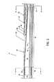
図1は、マニホールド12とカテーテル14とを有する本発明の実施の形態に係る迅速交換型(rapid exchange)の流体噴流血栓摘出装置10の視認可能な構成要素を示す平面図である。マニホールド12は、末端側に位置するルア(Luer)接続部材16と、歪取り部材18と、排出用分岐部20と、ねじ付き分岐端部22と、基部側に位置するルア接続部材24と、ねじ付き高圧接続ポート26とを含む。カテーテル14は、一体的で長尺な構造を有し、歪取り部材18から端部側へ延在し、複数の構成要素を含む。前記複数の構成要素は、以下に限定されないが、一体型の基部側排出用チューブ28と、一体型の半剛性を有する中間チューブ30と、一体型の末端側排出用チューブ32とが直列に接続されており、ガイドワイヤチューブ46(図3)及び他の特徴や構成要素は以下に説明される。基部側排出用チューブ28及び末端側排出用チューブ32は、網目状(braided)のポリイミドで形成され、最小限の肉厚を有し、疲労すること(exhaust)なく染料(dye)が流出しない特性を有するとともに、管構造を通じて押し出し可能(pushability)であり、なお且つ過度に固い特性にはならない。FIG. 1 is a plan view showing visible components of a rapid exchange fluid
一体型基部側排出用チューブ28の基部側端部34は、マニホールド12にルア接続部材16を使用して固定され、歪取り部材18を通じて、末端側端部36が半剛性中間チューブ30の基部側端部38(図3)の周辺で終端する部位まで延在する。一体型末端側排出用チューブ32の基部側端部40は、末端側に位置する管状部42(図3)の一部と整列し、設計上可撓性を持たすことが可能なテーパ付先端44まで末端側へ延在する。A
図2は、マニホールド12に接続される高圧流体源及び収集室を示す本発明に係る流体噴流血栓摘出装置10の平面図である。FIG. 2 is a plan view of the fluid
図3は、歪取り部材18に対して末端側の流体噴流血栓摘出装置10のカテーテル14の構成要素を示す分解斜視図であり、明確に図示するため、構成要素の長さが短縮されて示されている。カテーテル14の外見上の長さは、基部側排出用チューブ28と、半剛性中間チューブ30と、末端側排出用チューブ32と、ガイドワイヤチューブ46の短い部位とを含む結合された構成要素の外見上の長さとなっている。他の構成要素は、カテーテル14の内部に収容されるか、その周囲に存在している。FIG. 3 is an exploded perspective view showing the components of the
中空部78(図5)を有する高圧チューブ48は、前述のマニホールド12から基部側排出用チューブ28の中空部50と、半剛性中間チューブ30の中空部52と、末端側排出用チューブ32の中空部54(図12)とを通過し、流体噴流放射器56に接続されて終端している。前記高圧チューブ48は、さらに、排出用チューブ支持リング58に溶接や他の適切な手段によって取り付けられている。図12に示される通り、高圧チューブ48の末端側端部60と同様に、流体噴流放射器56は、末端側排出用チューブ32の中空部54に位置している。図12に示される通り、放射線不透過性マーカーバンド70は、末端側排出用チューブ32と末端側領域で整列して強制的に固定され、流体噴流放射器56に対し摩擦を有して保持するように係合している(in captured alignment and in translated frictional engagement)。図12に示される通り、排出用チューブ支持リング58は、末端側排出用チューブ32の中空部54内に放射線不透過性マーカーバンド72と整列するように配置される。前記放射線不透過性マーカーバンド72は、末端側排出用チューブ32に強制的に固定され、摩擦を有して係合している。中空部62を有するガイドワイヤチューブ46は、半剛性中間チューブ30から末端側に延在し、排出用チューブ支持リング58と、流体噴流放射器56の通路64と、末端側排出用チューブ32の中空部54とを通過し、末端側端部65がテーパ付先端44の末端側端部で固定されて(securely)終端している。テーパ付先端44内の中央にガイドワイヤチューブ46の末端側端部を係合させるように固定すると同時に、末端側排出用チューブ32の端部において末端に向かう方向で次第に可撓性を有するテーパ付先端44を形成するために、加熱してもよい。又は、テーパ付先端44は、低温延伸(cold draw down)処理や、接着剤や高分子再結合(polymer reintegration)によって物理的に接着することによって形成してもよい。テーパ付先端44及びガイドワイヤチューブ46は連続している。図4を参照して説明されるように、ガイドワイヤチューブ46の基部側端部66は、半剛性中間チューブ30の切り取られ丸みをつけられたスロット68に固定されるように収容される。複数の流出用オリフィス74a〜74n及び前記流出用オリフィス74a〜74nから末端側に離間した複数の流入用オリフィス76a〜76nが末端側排出用チューブ32の末端側領域周辺に含まれる。The high-
図4は、一体型の半剛性中間チューブ30を示す斜視図である。半剛性中間チューブ30は、代替的に剛性を有する部材でもよく、金属やプラスチック又は他の好適な物質を用いて、形成、型による成形、加工、押し出し成形、又は他の好適な方法で製作される。半剛性中間チューブ30は、より長尺に末端側に位置する末端側管状部42より小さな径を有する基部側管状部38を含む。半剛性中間チューブ30は、基部側に向かう方向に深さが減少するように切り取られ丸みをつけられた形状のスロット68を含み、前記スロット68は、末端側管状部42の大部分に延在するガイドワイヤチューブ46(図5)を収容する。前記スロット68は、末端側管状部42の末端側最端部において実質的に略半円形の弧状に形成される。その弧の形状は、円弧の半径が一定に維持された状態で、末端側管状部42の末端最側端部から基部側へ徐々に減少し、図5に示されるように、傾斜して連続する(transitional)ようにガイドワイヤチューブ46を収容する。半剛性中間チューブ30の内部にある中空部52は、高圧チューブ48を収容し、中空部50、54が形成されて、排出物の流出通路全体の一部として機能する。FIG. 4 is a perspective view showing an integrated semi-rigid
図5は、図1に示されるカテーテル14の5−5線に沿った断面図であり、図5に示される全ての参照符号は、上述された要素に対応している。特に、半剛性中間チューブ30が、基部側排出用チューブ28と、末端側排出用チューブ32と、ガイドワイヤチューブ46の基部側端部66と、夫々直接(intimately)係合している。基部側排出用チューブ28の末端側端部36と半剛性中間チューブ30とは、基部側排出用チューブ28の末端側端部36が半剛性中間チューブ30の小径な基部側管状部38に係合することにより、薄い形状を有して(low profile)接合する。接着剤、溶接、熱結合、熱収縮及び熱が発生するか又は発生しない結合による他の好適な方法を用いて、基部側排出用チューブ28の末端側端部36を半剛性中間チューブ30の小径な基部側管状部38に結合させる。ガイドワイヤチューブ46の基部側端部66が、半剛性中間チューブ30の切り取られ丸みをつけられた形状のスロット68に収容され、接着剤、溶接、又は他の好適な方法により固定される。ガイドワイヤチューブ46の基部側端部66は、末端側排出用チューブ32若しくは基部側排出用チューブ28の外周形状(outer profile)が所望の最小限のカテーテル側面形状を越えないような長さとなる。スロット68のうちガイドワイヤチューブ46の基部側端部66が存在しない基部側の部分は、構造上干渉することなくガイドワイヤを収容するように利用することも可能である。末端側排出用チューブ32の基部側端部40は、半剛性中間チューブ30の末端側管状部42の一部と直接係合し、接着剤、溶接、熱結合、熱収縮及び熱が発生するか又は発生しない結合による他の好適な方法を用いて結合する。また、中空部78を有する高圧チューブ48が中空部50、52及び54を通過することが図示されている。基部側排出用チューブ28の中空部50と、半剛性中間チューブ30の中空部52と、末端側排出用チューブ32の中空部54とが接続され、カテーテル14の全体に延在する排出用通路として機能する。FIG. 5 is a cross-sectional view of the
図6は、図4に示される一体型半剛性中間チューブ30の端面図であり、図6に示される全ての参照符号は、上述された要素に対応している。特に、円弧が最大となるスロット68の末端側最端部を図示している。FIG. 6 is an end view of the integral semi-rigid
図7は、図5に示されるカテーテル14の7−7線に沿った断面図であり、図7に示される全ての参照符号は、上述された要素に対応している。特に、排出用通路として機能する基部側排出用チューブ28の中空部50において、内部の障害物又は絞り(restrictions)が最小限にされている様子が図示されている。FIG. 7 is a cross-sectional view of the
図8は、図5に示されるカテーテル14の8−8線に沿った断面図であり、図8に示される全ての参照符号は、上述された要素に対応している。特に、ガイドワイヤチューブ46が、半剛性中間チューブ30のスロット68に整列して収容されている様子が図示されている。また、中空部50、52、54が直線状に整列し、カテーテル14を通る排出用通路として機能する様子が図示されている。FIG. 8 is a cross-sectional view of the
図9は、流体噴流放射器56、排出用チューブ支持リング58、高圧チューブ48の相互関係を示す分解斜視図である。排出用チューブ支持リング58は、溶接部80又は他の好適な接着方法を用いて高圧チューブ48の底面に固定される。これにより、排出用チューブ支持リング58を末端側排出用チューブ32の内部(中空部54)に沿った好適な位置に固定し、放射線不透過性マーカーバンド72による末端側排出用チューブ32上での加圧及び摩擦によって、排出用チューブ支持リング58が末端側排出用チューブ32と係合する。FIG. 9 is an exploded perspective view showing the relationship between the
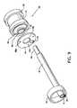
高圧チューブ48は、流体噴流放射器56と係合するために、高圧チューブ末端側端部60において縮径している。流体噴流放射器56を、図9、図10及び図11を参照して説明する。流体噴流放射器56は、外見上、スプールの一般的な形状のように構成される。流体噴流放射器56は、円筒状本体82と、環状マニホールド溝83と、中央管状延長部85と、マニホールドプレート86と、中央に位置する中央孔90と、偏心孔94とを含む。環状マニホールド溝83は、円筒状本体82の基部側端部における環状の溝として形成される。中央管状延長部85は、円筒状本体82の基部側端部から基部側へ延在し、環状マニホールド溝83と同軸である。マニホールドプレート86は、環状マニホールド溝83と整列し、さらに環状マニホールド溝83に近接する環状の平面部と整列し、複数の噴流オリフィス88a〜88nを有する。中央孔90には、中央管状延長部85が整列して嵌合(accommodate)する。マニホールドプレート86も、中央孔90と中央管状延長部85が接合(mate)する際に、円筒状本体82の末端側端部と実質的に整列する。通路64は、円筒状本体82の長手方向の軸と、中央管状延長部85の中心と、マニホールドプレート86の中央孔90の中心と、円筒状本体82に対する環状溝96の中心と、夫々整列する。その際、図10に示される通り、環状マニホールド84が形成される。ここで、マニホールドプレート86が環状マニホールド溝83と、流体噴流放射器56の近接する環状平面部とに接合し、複数の噴流オリフィス88a〜88n及び偏心孔94が環状マニホールド溝83及び環状マニホールド84と密接に連通するように配置(alignment)されている。The
食塩水若しくは他の好適な溶液等の高圧流体98が高圧チューブ48の中空部78を通じて流体噴流放射器56に送出され、環状マニホールド84を通じて複数の噴流オリフィス88a〜88nに配送され、高速噴流100が、後に詳述されるように基部側へ放射される。A
図12に示される通り、放射線不透過性マーカーバンド70及び流体噴流放射器56の円筒状本体82の環状溝96は、流体噴流放射器56及び当該流体噴流放射器56と関連する構成要素を末端側排出用チューブ32の末端側端部内で適切な部位に固定するために用いられる。放射線不透過性マーカーバンド70は、末端側排出用チューブ32の末端側端部に位置し、環状溝96と末端側排出用チューブ32とが重なる(co-located)領域に、末端側排出用チューブ32上での加圧及び摩擦によって、末端側排出用チューブ32と係合する。As shown in FIG. 12, the
図10は、図9に示される構成要素を組み立てた状態を示す一部断面側面図である。特に、高圧チューブ48の中空部78が環状マニホールド84に結合する関係が図示されている。高圧流体98は、中空部78を通って環状マニホールド84に送出され、噴流オリフィス88a〜88nを通じ高速噴流100となり、複数の噴流が基部側に向けて外部に放射される。マニホールドプレート86と円筒状本体82との共通な接合周辺部を結合する環状溶接部101と、中央管状延長部85とマニホールドプレート86との接合部を結合する他の環状溶接部103とによって、環状マニホールド84は一体化されている。環状溶接部105は、高圧チューブ48の末端側端部60を偏心孔94の内部で固定するように封止し、これにより中空部78と環状マニホールド84との一体的な結合を確保している。FIG. 10 is a partially sectional side view showing a state where the components shown in FIG. 9 are assembled. In particular, the relationship in which the
図11は、流体噴流放射器56の基部側端部を示す端面図であり、図11に示される全ての参照符号は、上述された要素に対応している。特に、噴流オリフィス88a〜88nが環状マニホールド84に対して整列して配置されており、噴流オリフィス88a〜88nを通じて高速噴流100が基部側へ放射される様子が図示されている。FIG. 11 is an end view showing the proximal end of the
図12は、図1に示される末端側排出用チューブ32の端部を示す12−12線に沿った断面図である。放射線不透過性マーカーバンド70、72が末端側排出用チューブ32の末端側端部に配置されている様子が図示されている。放射線不透過性マーカーバンド70は、末端側排出用チューブ32上に強制的に取り付けられ、末端側排出用チューブ32の一部と、流体噴流放射器56の環状溝96の全てあるいは一部とを摩擦を有して係合させる。このような摩擦を有する係合は、放射線不透過性マーカーバンド70の外径表面を末端側排出用チューブ32の大部分の通常の外径表面と比較して小径な(lesser)位置に位置決めするのに十分である。これにより、末端側排出用チューブ32の一部において通常の外径表面を越えて突出する要素がなくなり、カテーテル14が静脈や動脈等の内部で妨げられることなく滑らかに末端側あるいは基部側へ変位することが可能となる。放射線不透過性マーカーバンド70が末端側排出用チューブ32上に摩擦を有して係合しているとき、対向する湾曲環状面102、104が放射線不透過性マーカーバンド70の端部に近接して形成されているため、末端側排出用チューブ32の滑らかな表面に対し実質的に急激な段差(abrupt)が設けられることがない。湾曲環状面102、104は実質的に滑らかであり、カテーテル14を静脈や動脈等の内部で妨げられることなく滑らかに末端側あるいは基部側へ変位させる。放射線不透過性マーカーバンド70の場合とほぼ同じ方法で、放射線不透過性マーカーバンド72も、末端側排出用チューブ32上で強制的に取り付けられ、末端側排出用チューブ32の一部と排出用チューブ支持リング58とを摩擦を有して係合させる。このような摩擦を有する係合は、放射線不透過性マーカーバンド72の外径表面を末端側排出用チューブ32の大部分の通常の外径表面と比較して小径な位置に位置決めするのに十分である。これにより、末端側排出用チューブ32の一部において通常の外径表面を越えて突出する要素がなくなり、カテーテル14が静脈や動脈等の内部で妨げられることなく滑らかに末端側あるいは基部側へ変位することが可能となる。湾曲環状面106、108は実質的に滑らかであり、カテーテル14を静脈や動脈等の内部で妨げられることなく滑らかに末端側あるいは基部側へ変位させる。FIG. 12 is a cross-sectional view taken along line 12-12 showing an end of the distal-
末端側排出用チューブ32の末端側端部を、管や動脈等を通じて血栓付着物又は病巣の部位まで導入し通路を付与する構造が提供される。テーパが付けられずに丸みをつけられた端部と反対側のテーパ付先端44は、末端側へ挿入される際、血栓付着物や病巣を末端側へ前進させたり押したりすることなく血栓付着物や病巣を切断し、より簡単に貫通することが可能である。テーパ付先端44は末端側に向かって縮径しており、より柔軟に曲折した通路に対応することができる。曲折した通路に対応する際、テーパ付先端44に続く末端側排出用チューブ32の部分は、負圧による撓曲及び折曲に抗して末端側排出用チューブ32を補強する支持構造に左右される。特に、流入用オリフィス76a〜76n及び流出用オリフィス74a〜74nを含む場所あるいはその近傍の領域において負圧による撓曲及び折曲がある。排出用チューブ支持リング58及び流体噴流放射器56は、夫々流入用オリフィス76a〜76n及び流出用オリフィス74a〜74nの領域において末端側排出用チューブ32に沿って支持あるいは補強する構造の例である。排出用チューブ支持リング58及び流体噴流放射器56は、枠体(forms)として機能し、末端側排出用チューブ32の径を維持する。そのように支持することにより、より薄い壁の末端側排出用チューブ32を使用することを可能とし、外径を小さくできるだけでなく、中空部54をより大きく、より効果的に効率的なサイズとすることができる。また、このように支持することにより、カテーテル14が静脈や管に沿って押し出され又は前進する際に、捻れに対する支持となると同時に、末端側排出用チューブ32の径及び全体形状を維持することに寄与する。(4) A structure is provided in which the distal end of the distal-
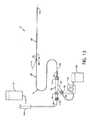
図13及び図14は、実施例1を示し、図13は、補助装置に接続される流体噴流血栓摘出装置10を示す図である。図14は、流体噴流血栓摘出装置10の使用方法を示す一部切欠断面図である。この実施例1は、上記において説明された図とともに、図13及び図14を参照することにより最もよく諒解されよう。FIGS. 13 and 14 show the first embodiment, and FIG. 13 is a diagram showing the fluid
図13において、補助装置に接続される流体噴流血栓摘出装置10がガイドワイヤ110上に係合している様子が示されている。事前に動脈又は静脈内に挿入(engaged)されたガイドワイヤ110は、まず末端側排出用チューブ32のテーパ付先端44においてガイドワイヤチューブ46の中空部62に係合する。さらに、ガイドワイヤ110は、半剛性を有する中間チューブ30におけるガイドワイヤチューブ46の基部側端部66で中空部62から外部に露出する。図13に示される通り、高圧流体源112及び高圧流体ポンプ114が、ねじ付き高圧接続ポート26を介し、ねじ付きナット116によって、又は、選択的に直接、マニホールド12に接続される。図13に示される通り、選択的排出用レギュレータ118及び収集室120が、ルア接続部材122によってマニホールド12の排出用分岐部20のねじ付き分岐端部22に接続される。FIG. 13 shows a state in which the fluid
図14は、流体噴流血栓摘出装置10の使用方法を示す一部切欠断面図であり、特に、血管124又は動脈等内の血栓付着物又は病巣126の部位において可撓性を有するテーパ付先端44を含む末端側排出用チューブ32の末端側端部が図示されている。食塩水(又は好適な流体)の複数の高速噴流100が流体噴流放射器56から基部側へ射出され、血栓付着物又は病巣126に衝突し移送する様子が図示されている。この図14に示される流体噴流放射器56の代わりに、他の流体噴流放射器を末端側排出用チューブ32の末端側端部内に配設し、1つ以上の高速噴流100を末端側排出用チューブ32の末端側又は長手方向付近に放射又は射出し、流体噴流放射器56において説明されたものと同じ目的を遂行してもよい。食塩水の高速噴流100は、流出用オリフィス74a〜74nを半径方向外側へ通過し、血管124の壁部に向かって外側に直交噴流128(低速噴流)を生成する。また、高速噴流100は、流入用オリフィス76a〜76nにおいて低圧の影響を受け、直交噴流128が周囲に向けて末端側へ流れ、血栓付着物又は病巣126に衝突し、引き剥がし力を与え、これを分解する。さらに、高速噴流100は、比較的低圧領域である流入用オリフィス76a〜76nを通じて血栓付着物又は病巣126の小片を巻き込むことにより、血栓をさらに解離させて微細な粒子として末端側排出用チューブの中空部54へ送出する(図12)。新鮮な食塩水と混合し解離したこの小片の一部が排出用チューブ中空部54を通じ摘出され、また、他の一部は、流出用オリフィス74a〜74nへ再び送出され、より多くの破片を分解し流入用オリフィス76a〜76nに戻って再循環する。このように、噴流オリフィス88a〜88nを通じて注入されるよりも、より多くの流れがシステムを循環する。例えば、噴流オリフィス88a〜88nを通じて送出されるよりも3〜10倍多くの流れがシステムを循環する。流入用オリフィス76a〜76nでの巻き込みは、高速噴流100による巻き込みに基づいている。流出は、高速噴流100及び流入用オリフィス76a〜76nによって巻き込まれる流体によって生成される内圧で付勢される。血餅(clot)の摘出は、流入及び流出用オリフィス76a〜76n、74a〜74n間での再循環パターンによって増加させることが可能である。前記再循環パターンは、壁部に付着した血栓上の引き剥がし力を最大限にする流れ領域を生成する。巻き込まれた血栓は微細な粒子に解離されるので、流出用オリフィス74a〜74nから出た粒子は、末端側への循環を実質的に妨げる大きさではなく、その多くは流入用オリフィス76a〜76nに再び巻き込まれる。流れのない場合又は流れが閉鎖バルーン等の他の装置に止められた場合においては、全ての粒子が摘出されて残余物が食塩水のみとなるように、物質を再循環して薄めることも可能である。FIG. 14 is a partially cutaway cross-sectional view illustrating the method of using the fluid
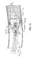
図15は、代替的な実施の形態として、歪取り部材18側の末端側における代替的なカテーテル14aの構成要素を示す分解斜視図である。明確に図示するため、構成要素の長さが縮小されて示されている。カテーテル14aで用いられる構成要素は、カテーテル14で用いられる構成要素とほぼ同じであるが、異なる箇所もあるため、カテーテル14aに参照符号を変える。流体噴流放射器56は双方向流体噴流放射器130に参照符号を変え、末端側排出用チューブ32は末端側排出用チューブ132に参照符号を変える。他の関連する構成要素は、図示されるように配置され、利用される。カテーテル14aの外見の長さは、基部側排出用チューブ28、半剛性中間チューブ30、末端側排出用チューブ132及びガイドワイヤチューブ46の小部分を含む接合された構成要素の外見上の長さとなっている。他の構成要素や構造は、カテーテル14aの内部に収容されるか、周囲に存在している。FIG. 15 is an exploded perspective view showing components of an
中空部78を有する高圧チューブ48(図5)は、マニホールド12から延在し、上述したように、基部側排出用チューブ28の中空部50を通り、半剛性中間チューブ30の中空部52を通り、末端側排出用チューブ132の中空部134(図18)を通り、双方向流体噴流放射器130に接続されて終端する。高圧チューブ48も、排出用チューブ支持リング58を貫通するように、当該排出用チューブ支持リング58に溶接等の好適な手段で接着される。図18に示される通り、高圧チューブ48の末端側端部60だけでなく双方向流体噴流放射器130が、末端側排出用チューブ132の中空部134の末端側に位置している。放射線不透過性マーカーバンド70が末端側排出用チューブ132上の末端側領域周辺に整列し、強制的に固定され、双方向流体噴流放射器130を摩擦を有して保持するように係合している。排出用チューブ支持リング58は、末端側排出用チューブ132の中空部134内に放射線不透過性マーカーバンド72と整列するように位置する。図18に示される通り、放射線不透過性マーカーバンド72は、末端側排出用チューブ132上に整列し、強制的に固定され、摩擦を有して係合している。中空部62を有するガイドワイヤチューブ46は、図18に示される通り、半剛性中間チューブ30から末端側へ延在し、排出用チューブ支持リング58を通り、末端側排出用チューブ132の中空部134へ通じているが、双方向流体噴流放射器130の通路172を通って、末端側端部65が先端136の末端側端部において固定されるように終端する。ガイドワイヤチューブ46の基部側端部66は、図4を参照して説明したように、半剛性中間チューブ30のスロット68に固定されるように収容される。複数の流入用オリフィスが末端側排出用チューブ132の末端側領域周辺に沿って配置される。前記複数の流入用オリフィスは、放射線不透過性マーカーバンド70及び双方向流体噴流放射器130(図18)に対して末端側近傍に並列する流入用オリフィス138a〜138nを含む。さらに、末端側排出用チューブ132の末端側領域周辺に沿って配置され、放射線不透過性マーカーバンド70及び双方向流体噴流放射器130(図18)の末端側に並列する複数の流出用オリフィス140a〜140nを含む。加えて、同じく図18に示される通り、流入用オリフィス142が放射線不透過性マーカーバンド70に対して基部側の近くに並列するように配置される。A high-pressure tube 48 (FIG. 5) having a
図16は、双方向流体噴流放射器130、排出用チューブ支持リング58、高圧チューブ48の相互関係を示す分解斜視図である。排出用チューブ支持リング58は、溶接部80又は他の好適な接着方法で、高圧チューブ48の底面に固定される。これにより、排出用チューブ支持リング58を末端側排出用チューブ132の内部(中空部134)に沿った好適な位置に固定し、放射線不透過性マーカーバンド72による末端側排出用チューブ132上での加圧及び摩擦によって、排出用チューブ支持リング58が末端側排出用チューブ132と係合する。FIG. 16 is an exploded perspective view showing the interrelationship between the bidirectional
高圧チューブ48は、高圧チューブ末端側端部60において縮径し、双方向流体噴流放射器130と係合する。双方向流体噴流放射器130は、多くの点において流体噴流放射器56と同様であり、図16及び図17を参照して説明される。双方向流体噴流放射器130は、外見上糸巻きの一般的な形状に似せて構成される。双方向流体噴流放射器130は、円筒状本体144と、環状マニホールド溝146と、中央管状延長部148と、マニホールドプレート150と、中央に位置する中央孔154と、偏心孔156とを含む。環状マニホールド溝146は、円筒状本体144の基部側端部における環状の溝として形成される。中央管状延長部148は、円筒状本体144の基部側端部から基部側へ延在し、環状マニホールド溝146と同軸である。マニホールドプレート150は、環状マニホールド溝146と整列し、環状マニホールド溝146に近接する環状の平面部と整列し、噴流オリフィス152を有する。中央孔154は、整列して中央管状延長部148が嵌合する。マニホールドプレート150も、中央孔154と中央管状延長部148が接合する際に、円筒状本体144の末端側端部と実質的に整列する。その際、図17に示される通り、環状マニホールド158が形成される。ここで、マニホールドプレート150が環状マニホールド溝146と、双方向流体噴流放射器130の近接する環状平面部とに接合し、噴流オリフィス152及び偏心孔156が環状マニホールド溝146及び環状マニホールド158と密接に連通するように配置されている。双方向流体噴流放射器130は、さらに、環状マニホールド158と反対側に他の環状マニホールド160(図17)を含み、環状マニホールド160は、環状マニホールド158と同様の形状を有し、双方向流体噴流放射器130の末端側端部に配置される。The
図16及び図17を参照し、双方向流体噴流放射器130の末端側端部にある環状マニホールド160及び他の構成を説明する。双方向流体噴流放射器130の末端側端部は、環状マニホールド溝162と、中央管状延長部164と、マニホールドプレート166と、中央に位置する中央孔170とを含む。環状マニホールド溝162は、円筒状本体144の末端側端部における環状の溝として形成される。中央管状延長部164は、円筒状本体144の末端側端部から末端側へ延在し、環状マニホールド溝162と同軸である。マニホールドプレート166は、環状マニホールド溝162及び環状の平面部と整列し、前記環状の平面部が環状マニホールド溝162に近接し、マニホールドプレート166に対し分散して配置された複数の噴流オリフィス168a〜168nを有する。中央孔170は、整列して中央管状延長部164が嵌合する。マニホールドプレート166も、中央孔170と中央管状延長部164が接合する際に、円筒状本体144の末端側端部と実質的に整列する。その際、環状マニホールド160が形成される。ここで、マニホールドプレート166が環状マニホールド溝162と、双方向流体噴流放射器130の近接する環状平面部とに接合し、噴流オリフィス168a〜168n及び中央孔170が環状マニホールド溝162及び環状マニホールド160と密接に連通するように配置されている。通路172が、円筒状本体144の長手方向の軸と、マニホールドプレート150、166の中央孔154、170の中心と、円筒状本体144に対する環状溝174の中心と、夫々整列する。他の通路178は、円筒状本体144を通って、基部側に位置する環状マニホールド158と末端側に位置する環状マニホールド160との間を連通するように延在する。With reference to FIGS. 16 and 17, the
図18に示される通り、双方向流体噴流放射器130の円筒状本体144の周囲に位置する放射線不透過性マーカーバンド70及び環状溝174は、末端側排出用チューブ132の末端側端部内における適切な位置に双方向流体噴流放射器130及び関連する構成要素を固定するために用いられる。放射線不透過性マーカーバンド70は、末端側排出用チューブ132の末端側端部上に位置付けられ、放射線不透過性マーカーバンド70による末端側排出用チューブ132上での加圧及び摩擦によって、環状溝174と末端側排出用チューブ132とが一致する領域において、末端側排出用チューブ132と係合する。As shown in FIG. 18, the
図17は、図16に示される構成要素を組み立てた状態を示す一部断面側面図である。特に、高圧チューブ48の中空部78に対する環状マニホールド158と、通路178と、環状マニホールド160との接続関係が図示されている。中空部78を通じて環状マニホールド158に送出される高圧流体176が、噴流オリフィス152を通じて高速噴流180の形態で外側及び基部側に放射される。中空部78を通じて環状マニホールド158に送出される高圧流体176は、相互接続する通路178を介して環状マニホールド160と連通し、噴流オリフィス168a〜168nを通じて高速噴流182の形態で外側及び末端側に放射される。マニホールドプレート150と双方向流体噴流放射器130の近接する円筒状本体144との共通な接合周辺部を結合する環状溶接部184と、中央管状延長部148とマニホールドプレート150との接合部を結合する他の環状溶接部186とによって、環状マニホールド158は一体化している。同様に、マニホールドプレート166と双方向流体噴流放射器130の近接する円筒状本体144との共通な接合周辺部を結合する環状溶接部188と、中央管状延長部164とマニホールドプレート166との接合部を結合する他の環状溶接部190とによって、環状マニホールド160は一体化されている。環状溶接部192は、高圧チューブ48の末端側端部60を偏心孔156の内部で確実に封止し、これにより中空部78と環状マニホールド158との一体的な結合を確保している。FIG. 17 is a partial cross-sectional side view showing a state where the components shown in FIG. 16 are assembled. In particular, the connection relationship between the
図18は、図1の12−12線に沿って示されるように、末端側排出用チューブ132の末端側端部を示す断面図であり、双方向流体噴流放射器130に対する末端側に位置する流入用オリフィス138a〜138n及び流出用オリフィス140a〜140nと、基部側に位置する流入用オリフィス142との関係を図示している。上述したように、放射線不透過性マーカーバンド70、72が末端側排出用チューブ132の末端側端部上に配置され、湾曲する環状面102、104、106及び108が形成される様子が図示されている。末端側に位置する放射線不透過性マーカーバンド70が末端側排出用チューブ132上に強制的に固定され、末端側排出用チューブ132の一部と双方向流体噴流放射器130の環状溝174の全体又は一部とが摩擦を有して係合している。このような摩擦を有する係合は、放射線不透過性マーカーバンド70の外径表面を末端側排出用チューブ132の大部分の通常の外径表面と比較して小径な位置に位置決めするのに十分である。これにより、末端側排出用チューブ132の一部において通常の外径表面を越えて突出する要素がなくなり、上述したように、カテーテル14aが静脈や動脈等の内部で妨げられることなく滑らかに末端側あるいは基部側へ変位することが可能となる。FIG. 18 is a cross-sectional view showing the distal end of the
双方向流体噴流放射器130と、末端側排出用チューブ132と、関連する構成要素を含むカテーテル14aとを備える流体噴流血栓摘出装置10の実施例2は、特に、図19を参照することにより最もよく諒解されよう。図19は、流体噴流血栓摘出装置10におけるカテーテル14aの末端側端部の使用方法を示す一部切欠断面図である。末端側排出用チューブ132は、図3に関連する説明において、末端側排出用チューブ32を末端側排出用チューブ132に置き換えた説明による方法で構成及び接続される。
図19は、特に、血管124又は動脈等内の血栓付着物又は病巣126の部位に配置される先端136を含む末端側排出用チューブ132の末端側端部を図示している。高速噴流は、双方向流体噴流放射器130から互いに反対側の方向に生ずる。双方向流体噴流放射器130から末端側へ放射される高速噴流182が、血栓付着物又は病巣126を分解し、解離させ、又は、再解離させる。さらに、双方向流体噴流放射器130から基部側へ放射される高速噴流180が、解離、又は再解離した血栓付着物又は病巣126を末端側排出用チューブ132の中空部134から摘出する。FIG. 19 illustrates the distal end of a
末端側への噴流に関し、図17にも示されるような食塩水(又は他の好適な流体)の複数の高速噴流182が双方向流体噴流放射器130から末端側へ放射され、血栓付着物又は病巣126に衝突し流出させる様子が図示されている。食塩水の高速噴流182は、流出用オリフィス140a〜140nを通過し半径方向外側へ、血管124の壁部に向かって外側に直交噴流194(低速噴流)を生成する。また、高速噴流182は、流入用オリフィス138a〜138nにおける低圧の影響を受け、直交噴流194が周囲を基部側へ流れ、血栓付着物又は病巣126に衝突し、引き剥がし力を与え、これを分解する。さらに、直交噴流194は、比較的低圧領域である流入用オリフィス138a〜138nを通じて、血栓付着物又は病巣126の小片を巻き込み、付勢することにより血栓がさらに解離して微細な粒子として高速噴流182に戻る。新鮮な食塩水と混合し解離したこの小片の一部が後述するように流入用オリフィス142を通って末端側排出用中空部134を通じ摘出され、また、他の一部は、流入用オリフィス138a〜138nに流入し流出用オリフィス140a〜140nへ再び送出され、より多くの小片を分解し流入用オリフィス138a〜138nに戻って再循環する。このように、噴流オリフィス168a〜168nを通じて注入されるよりも多くの流れがシステムを循環する。例えば、噴流オリフィス168a〜168nを通じて送出されるよりも3〜10倍多くの流れがシステムを循環する。流入用オリフィス138a〜138nでの巻き込みは、高速噴流182による巻き込みに基づいている。血餅摘出は、流入及び流出用オリフィス138a〜138n、140a〜140n間での再循環パターンによって増加させることが可能である。前記再循環パターンは、壁部に付着した血栓上の引き剥がし力を最大限にする流れ領域を生成する。巻き込まれた血栓は微細な粒子に解離されるので、流出用オリフィス140a〜140nから出た粒子は、末端側への循環を実質的に妨げる大きさではなく、その多くは、高速で流入用オリフィス138a〜138nに再び巻き込まれるか、又は、流入用オリフィス142を通じ排出される。With respect to the distal jet, a plurality of
基部側への噴流に関し、図17にも示されるような食塩水(又は他の好適な流体)の高速噴流180が双方向流体噴流放射器130から基部側に指向する噴流オリフィス152によって基部側へ放射され、比較的低圧を流入用オリフィス142に生成し、解離又は再解離されて食塩水に浮遊する血栓付着物又は病巣126を導入して流出させる様子が図示されている。これまでに参照した図面には、噴流オリフィス152がただ1つだけ図示されていたが、基部側に指向する噴流オリフィスを複数設けてもよい。解離又は再解離されて食塩水に浮遊する血栓付着物又は病巣126は、末端側排出用チューブ132の中空部134を通じて上記のように収集される。With respect to the proximal jet, a
流れのない場合又は流れが閉鎖バルーン等の他の装置に止められた場合においては、全ての粒子が摘出されて残余物が食塩水のみとなるように、物質を再循環し薄めることも可能である。If there is no flow or the flow is stopped by another device, such as a closed balloon, it is possible to recirculate and dilute the material so that all particles are extracted and the only residue is saline. is there.
本発明の明らかな範囲から逸脱することなく、様々な改変が可能である。様 々 Various modifications are possible without departing from the apparent scope of the invention.
10…流体噴流血栓摘出装置
12…マニホールド
14、14a…カテーテル
16、24、122…ルア接続部材
18…歪取り部材
20…排出用分岐部
22…ねじ付き分岐端部
26…ねじ付き高圧接続ポート
28…基部側排出用チューブ
30…半剛性中間チューブ
32、132…末端側排出用チューブ
46…ガイドワイヤチューブ
48…高圧チューブ
56…流体噴流放射器
58…排出用チューブ支持リング
70、72…放射線不透過性マーカーバンド
74a〜74n、140a〜140n…流出用オリフィス
76a〜76n、138a〜138n、142…流入用オリフィス
82、144…円筒状本体
86、150、166…マニホールドプレート
98、176…高圧流体
100、180、182…高速噴流
110…ガイドワイヤ
112…高圧流体源
114…高圧流体ポンプ
118…選択的排出用レギュレータ
120…収集室
124…血管
126…血栓付着物又は病巣
128、194…直交噴流
130…双方向流体噴流放射器
DESCRIPTION OF
Claims (36)
Translated fromJapanesea.基部側端部及び末端側端部を備える長尺な一体型構造体であって、前記基部側端部と前記末端側端部との間で長さを規定し、
b.前記長尺な一体型構造体は、前記長さに沿って延在する管状手段を有し、前記管状手段は、前記長尺な一体型構造体の前記基部側端部から前記末端側端部へ高圧流体を流す少なくとも1つの第1通路を規定し、前記第1通路は、基部側端部及び末端側端部を有し、前記第1通路は、高圧流体を前記第1通路の前記基部側端部へ供給するための高圧接続手段を有し、
c.前記長尺な一体型構造体の長さの一部に延在する末端側排出用チューブであって、前記末端側排出用チューブは基部側端部及び末端側端部を有し、前記末端側排出用チューブは、前記長尺な一体型構造体の前記末端側端部近傍に位置し、前記末端側排出用チューブは、少なくとも1つの流入用オリフィス及び少なくとも1つの流出用オリフィスを有し、
d.前記長尺な一体型構造体の長さの一部に延在する基部側排出用チューブであって、前記基部側排出用チューブは、基部側端部及び末端側端部を有し、前記基部側排出用チューブは、前記長尺な一体型構造体の前記基部側端部近傍に位置し、前記基部側排出用チューブの前記基部側端部が排出用結合手段と連通し、
e.前記末端側排出用チューブの前記基部側端部近傍から前記末端側排出用チューブの前記末端側端部近傍まで延在するガイドワイヤチューブであって、前記ガイドワイヤチューブは、前記末端側排出用チューブの前記基部側端部近傍における前記長尺な一体型構造体の外部の1地点から前記末端側排出用チューブの前記末端側端部へガイドワイヤを通過させ、
f.前記末端側排出用チューブの前記基部側端部と前記基部側排出用チューブの前記末端側端部との間に流体を連通させる半剛性中間チューブであって、前記半剛性中間チューブは、切り取られ丸みをつけられたスロットを有し、前記スロットは、前記ガイドワイヤチューブを前記末端側排出用チューブの前記基部側端部近傍に装着させ、
g.前記第1通路と連通する噴流放射器であって、前記噴流放射器は、少なくとも1つの噴流オリフィスを有し、前記少なくとも1つの噴流オリフィスは、高圧流体の通過によって高速噴流を生成するとともに、少なくとも1つの流体噴流を前記末端側排出用チューブに指向させ、周囲の血液又は脈管の他の流体を前記流入用オリフィスを通じて前記末端側排出用チューブ内に巻き込み、高圧な領域を生成し、
h.前記流出用オリフィスは、血液又は他の流体及び破片の通過によって直交噴流を生成し、
i.前記末端側排出用チューブと、前記半剛性中間チューブと、前記基部側排出用チューブは、前記長尺な一体型構造体の前記末端側端部から前記長尺な一体型構造体の前記基部側端部へ血栓、他の不要組織、破片を移送するために流体を通過させる
ことを特徴とする流体噴流装置。A fluid jet device that breaks down and separates tissue or other materials from biological or synthetic vessels or body cavities,
a. A long integrated structure having a base end and a distal end, defining a length between the base end and the distal end,
b. The elongate unitary structure includes tubular means extending along the length, the tubular means comprising a proximal end to the distal end of the elongate unitary structure. Defining at least one first passage through which high pressure fluid flows, the first passage having a proximal end and a distal end, wherein the first passage directs high pressure fluid through the base of the first passage. Having high pressure connection means for feeding to the side end,
c. A distal discharge tube extending over a portion of the length of the elongated integral structure, the distal discharge tube having a proximal end and a distal end; A discharge tube located proximate the distal end of the elongated integral structure, the distal discharge tube having at least one inflow orifice and at least one outflow orifice;
d. A base-side discharge tube extending a part of the length of the elongated integrated structure, wherein the base-side discharge tube has a base-side end and a terminal-side end; The side discharge tube is located near the base side end of the elongated integrated structure, and the base side end of the base side discharge tube communicates with a discharge coupling means,
e. A guidewire tube extending from near the base end of the distal discharge tube to near the distal end of the distal discharge tube, wherein the guidewire tube is the distal discharge tube. Passing a guide wire from a point outside the elongated integrated structure near the base end to the distal end of the distal discharge tube,
f. A semi-rigid intermediate tube for communicating fluid between the base end of the distal discharge tube and the distal end of the base discharge tube, wherein the semi-rigid intermediate tube is cut off. A slot having a rounded slot, the slot mounting the guidewire tube near the base end of the distal discharge tube;
g. A jet radiator communicating with the first passage, the jet radiator having at least one jet orifice, wherein the at least one jet orifice generates a high-speed jet by passage of a high-pressure fluid; Directing one fluid jet into the distal discharge tube and entraining surrounding blood or other fluid in the vessel through the inlet orifice into the distal discharge tube to create a high pressure region;
h. The outflow orifice creates an orthogonal jet by the passage of blood or other fluids and debris;
i. The distal-side discharge tube, the semi-rigid intermediate tube, and the base-side discharge tube are connected to the base side of the elongated integrated structure from the distal end of the elongated integrated structure. A fluid jet device for passing fluid to transport thrombus, other unwanted tissue, and debris to an end.
a.高圧供給チューブと、
b.噴流放射器と、
c.末端側排出用チューブと、
d.基部側排出用チューブと、
e.半剛性中間チューブと、
f.ガイドワイヤチューブと、
を備えることを特徴とする流体噴流装置。A fluid jet device that breaks down and separates tissue or other materials from biological or synthetic vessels or body cavities,
a. A high pressure supply tube,
b. A jet radiator,
c. A distal discharge tube,
d. A base side discharge tube,
e. A semi-rigid intermediate tube,
f. A guidewire tube,
A fluid jet device comprising:
a.高圧供給チューブと、基部側高圧供給接続体と、噴流放射器と、末端側排出用チューブと、基部側排出用チューブと、基部側排出用接続体と、半剛性中間チューブと、ガイドワイヤチューブと、を有するカテーテルと、
b.ガイドワイヤと、
c.前記基部側高圧供給接続体に接続される高圧流体源と、
d.前記基部側排出用接続体に接続される排出用収集手段と、
を備えることを特徴とする流体噴流システム。In a fluid jet system,
a. A high-pressure supply tube, a base-side high-pressure supply connector, a jet radiator, a distal discharge tube, a base-side discharge tube, a base-side discharge connector, a semi-rigid intermediate tube, and a guide wire tube. A catheter having:
b. A guide wire,
c. A high pressure fluid source connected to the base side high pressure supply connection,
d. Discharge collecting means connected to the base-side discharge connector,
A fluid jet system comprising:
a.前記末端側排出用チューブ内の少なくとも1つの流入用オリフィスと、少なくとも1つの流出用オリフィスと、
b.前記噴流放射器内の少なくとも1つのオリフィスと、を備え、前記少なくとも1つのオリフィスは、少なくとも1つの流体噴流を前記末端側排出用チューブに指向させ、周囲の血液又は他の流体を前記流入用オリフィスを通じて前記末端側排出用チューブ内へ巻き込み、高圧な領域を生成し、
c.前記流出用オリフィスは、血液又は他の流体及び破片の通過によって直交噴流を生成する
ことを特徴とする流体噴流システム。The system of claim 12, further comprising:
a. At least one inflow orifice in the distal discharge tube, and at least one outflow orifice;
b. At least one orifice in the jet radiator, the at least one orifice directing at least one fluid jet to the distal discharge tube and directing surrounding blood or other fluid to the input orifice. Through the distal discharge tube to create a high pressure area,
c. A fluid jet system, wherein the outflow orifice generates an orthogonal jet by passage of blood or other fluids and debris.
a.基部側カテーテルチューブと、末端側カテーテルチューブと、ガイドワイヤチューブと、切り取られ丸みをつけられた形状のスロットを有する半剛性中間チューブと、を設ける工程であって、夫々のチューブは、基部側端部及び末端側端部を有し、前記スロットは、前記半剛性中間チューブの前記基部側端部よりも前記半剛性中間チューブの前記末端側端部において深く、
b.前記ガイドワイヤチューブを前記末端側カテーテルチューブに通過させる工程と、
c.前記ガイドワイヤチューブの前記基部側端部が、前記スロットの端部のうち深い方の端部内に装着されるように、前記半剛性中間チューブの前記末端側端部を前記末端側カテーテルチューブの前記基部側端部に接続する工程と、
d.前記ガイドワイヤチューブの前記基部側端部は、前記半剛性中間チューブの前記スロットに位置するとともに、前記ガイドワイヤチューブの前記末端側端部は、前記末端側カテーテルチューブの前記末端側端部近傍に位置し、
e.前記基部側カテーテルチューブの前記末端側端部を前記半剛性中間チューブの前記基部側端部に接続する工程と、
を含むことを特徴とするカテーテルの組立方法。In a method for assembling a catheter,
a. Providing a proximal catheter tube, a distal catheter tube, a guidewire tube, and a semi-rigid intermediate tube having a slot that is cut and rounded, wherein each tube has a proximal end. And a slot, wherein the slot is deeper at the distal end of the semi-rigid intermediate tube than at the base end of the semi-rigid intermediate tube;
b. Passing the guidewire tube through the distal catheter tube;
c. The distal end of the semi-rigid intermediate tube is attached to the distal catheter tube such that the proximal end of the guidewire tube is mounted within the deeper end of the slot. Connecting to the base end,
d. The proximal end of the guidewire tube is located in the slot of the semi-rigid intermediate tube, and the distal end of the guidewire tube is near the distal end of the distal catheter tube. Position to,
e. Connecting the distal end of the proximal catheter tube to the proximal end of the semi-rigid intermediate tube;
A method for assembling a catheter, comprising:
a.基部側排出用チューブと、末端側排出用チューブと、ガイドワイヤチューブと、高圧供給チューブと、噴流放射器と、切り取られ丸みをつけられた形状のスロットを有する半剛性中間チューブと、を設ける工程であって、夫々のチューブは、基部側端部及び末端側端部を有し、前記スロットは、前記半剛性中間チューブの前記基部側端部よりも前記半剛性中間チューブの前記末端側端部において深く、
b.前記ガイドワイヤチューブを前記末端側排出用チューブに通過させる工程と、
c.前記ガイドワイヤチューブの前記基部側端部が、前記スロットの端部のうち深い方の端部内に装着されるように、前記半剛性中間チューブの前記末端側端部を前記末端側排出用チューブの前記基部側端部に接続する工程と、
d.前記ガイドワイヤチューブの前記基部側端部は、前記半剛性中間チューブの前記スロットに位置するとともに、前記ガイドワイヤチューブの前記末端側端部は、前記末端側排出用チューブの前記末端側端部近傍に位置し、
e.前記基部側排出用チューブの前記末端側端部を前記半剛性中間チューブの前記基部側端部に接続する工程と、
f.前記高圧供給チューブを前記基部側排出用チューブと、前記半剛性中間チューブと、前記末端側排出用チューブとに通過させる工程と、
g.前記末端側排出用チューブの前記末端側端部近傍に、前記噴流放射器を、配置させる工程と、
を含むことを特徴とする流体噴流装置の組立方法。In the method for assembling a fluid jet device,
a. Providing a proximal discharge tube, a distal discharge tube, a guidewire tube, a high pressure supply tube, a jet radiator, and a semi-rigid intermediate tube having a cut-out rounded shaped slot. Wherein each tube has a proximal end and a distal end, and wherein the slot is more distal than the proximal end of the semi-rigid intermediate tube than the distal end of the semi-rigid intermediate tube. Deep in
b. Passing the guidewire tube through the distal discharge tube;
c. Connect the distal end of the semi-rigid intermediate tube to the distal discharge tube such that the proximal end of the guidewire tube is mounted within the deeper end of the slot. Connecting to the base-side end;
d. The proximal end of the guidewire tube is located in the slot of the semi-rigid intermediate tube, and the distal end of the guidewire tube is near the distal end of the distal discharge tube. Located in
e. Connecting the distal end of the base side discharge tube to the base end of the semi-rigid intermediate tube;
f. Passing the high-pressure supply tube through the base-side discharge tube, the semi-rigid intermediate tube, and the distal-side discharge tube;
g. A step of disposing the jet radiator in the vicinity of the distal end of the distal discharge tube,
A method for assembling a fluid jet device, comprising:
a.基部側排出用チューブと、末端側排出用チューブと、半剛性中間チューブと、ガイドワイヤチューブと、高圧中空部と、基部側高圧接続体と、末端側噴流放射器とを含む流体噴流カテーテルと、ガイドワイヤとを設ける工程と、
b.前記ガイドワイヤを脈管構造に通過させ、管における不要物質を含む場所を通り過ぎるように前進させる工程と、
c.前記ガイドワイヤを前記ガイドワイヤチューブに通過させて前記流体噴流カテーテルを導入し、前記流体噴流カテーテルを前記不要物質を含む場所まで前記ガイドワイヤに沿って前進させる工程と、
d.高圧な食塩水又は他の高圧流体を、前記基部側高圧接続体を介し前記高圧中空部に供給し、前記噴流放射器から少なくとも1つの高速流体噴流を放射し、流入用オリフィスを介し前記末端側排出用チューブ内に不要物質を巻き込み、前記不要物質を解離させ、前記末端側排出用チューブと、前記半剛性中間チューブと、前記基部側排出用チューブとに沿って基部側に前記不要物質を移動させ、体から摘出する工程と、
を含むことを特徴とする脈管又は体腔から不要物質を摘出する方法。In a method of extracting unnecessary substances from a vessel or a body cavity,
a. Fluid jet catheter including a base discharge tube, a distal discharge tube, a semi-rigid intermediate tube, a guide wire tube, a high pressure hollow portion, a base high pressure connector, and a terminal jet radiator, Providing a guide wire;
b. Passing the guidewire through the vasculature and advancing past the site of the vessel containing the unwanted material;
c. Introducing the fluid jet catheter by passing the guide wire through the guide wire tube, and advancing the fluid jet catheter along the guide wire to a location containing the unnecessary substance;
d. Supplying high-pressure saline or other high-pressure fluid to the high-pressure hollow through the base-side high-pressure connector, radiating at least one high-speed fluid jet from the jet radiator, and passing the distal side through an inflow orifice; Unnecessary substances are entrapped in the discharge tube to dissociate the unnecessary substances, and the unnecessary substances are moved to the base side along the distal discharge tube, the semi-rigid intermediate tube, and the base discharge tube. Let it be removed from the body,
A method for extracting unnecessary substances from a vessel or a body cavity, comprising:
a.排出用調節手段を設ける工程と、
b.前記排出用調節手段を用いて、前記基部側排出用チューブに沿って前記脈管又は体腔から流体及び前記不要物質を摘出する速度を調節する工程と、
を含むことを特徴とする脈管又は体腔から不要物質を摘出する方法。
36. The method of claim 35, further comprising:
a. Providing a discharge adjusting means;
b. Using the discharge adjustment means, adjusting the speed of extracting fluid and the unnecessary substance from the vessel or body cavity along the proximal discharge tube,
A method for extracting unnecessary substances from a vessel or a body cavity, comprising:
Applications Claiming Priority (1)
| Application Number | Priority Date | Filing Date | Title |
|---|---|---|---|
| US10/198,264US6875193B1 (en) | 1998-02-06 | 2002-07-16 | Rapid exchange fluid jet thrombectomy device and method |
Publications (1)
| Publication Number | Publication Date |
|---|---|
| JP2004033779Atrue JP2004033779A (en) | 2004-02-05 |
Family
ID=29780206
Family Applications (1)
| Application Number | Title | Priority Date | Filing Date |
|---|---|---|---|
| JP2003275580APendingJP2004033779A (en) | 2002-07-16 | 2003-07-16 | Fluid jet thrombectomy apparatus and its method |
Country Status (5)
| Country | Link |
|---|---|
| US (1) | US6875193B1 (en) |
| EP (1) | EP1382366B1 (en) |
| JP (1) | JP2004033779A (en) |
| AT (1) | ATE448823T1 (en) |
| DE (1) | DE60330095D1 (en) |
Cited By (3)
| Publication number | Priority date | Publication date | Assignee | Title |
|---|---|---|---|---|
| WO2006062023A1 (en)* | 2004-12-07 | 2006-06-15 | Nipro Corporation | Thrombus suction catheter with excellent passableness |
| JP2021514711A (en)* | 2018-02-21 | 2021-06-17 | ユナイテッド ステイツ エンドスコピー グループ,インコーポレイテッド | Devices and methods for fluid distribution from catheters |
| JP2022536050A (en)* | 2019-06-10 | 2022-08-12 | スミス・アンド・ネフュー・アジア・パシフィク・ピーティーイー・リミテッド | Water jet debridement and wound bed preparation |
Families Citing this family (91)
| Publication number | Priority date | Publication date | Assignee | Title |
|---|---|---|---|---|
| US7879022B2 (en)* | 1998-02-06 | 2011-02-01 | Medrad, Inc. | Rapid exchange fluid jet thrombectomy device and method |
| US9586023B2 (en) | 1998-02-06 | 2017-03-07 | Boston Scientific Limited | Direct stream hydrodynamic catheter system |
| US10092313B2 (en) | 2000-04-05 | 2018-10-09 | Boston Scientific Limited | Medical sealed tubular structures |
| EP1441777A4 (en)* | 2001-07-17 | 2007-05-30 | Kerberos Proximal Solutions | Fluid exchange system for controlled and localized irrigation and aspiration |
| AU2002350164A1 (en)* | 2001-11-08 | 2003-05-19 | William D. Hare | Rapid exchange catheter with stent deployment, therapeutic infusion, and lesion sampling features |
| US7163531B2 (en)* | 2002-08-19 | 2007-01-16 | Baxter International, Inc. | User-friendly catheter connection adapters for optimized connection to multiple lumen catheters |
| US20040127932A1 (en)* | 2002-09-12 | 2004-07-01 | Shah Tilak M. | Dip-molded polymeric medical devices with reverse thickness gradient, and method of making same |
| US20040230219A1 (en)* | 2003-05-12 | 2004-11-18 | Roucher Leo R. | Anchoring, supporting and centering catheter system for treating chronic total occlusions |
| US20060129091A1 (en) | 2004-12-10 | 2006-06-15 | Possis Medical, Inc. | Enhanced cross stream mechanical thrombectomy catheter with backloading manifold |
| US20060058723A1 (en)* | 2004-09-15 | 2006-03-16 | Pratt William R | Apparatus and method for cleaning a surgically prepared bone surface |
| US8012117B2 (en)* | 2007-02-06 | 2011-09-06 | Medrad, Inc. | Miniature flexible thrombectomy catheter |
| US20080188793A1 (en)* | 2007-02-06 | 2008-08-07 | Possis Medical, Inc. | Miniature flexible thrombectomy catheter |
| US8162878B2 (en)* | 2005-12-05 | 2012-04-24 | Medrad, Inc. | Exhaust-pressure-operated balloon catheter system |
| US7615037B2 (en) | 2005-12-14 | 2009-11-10 | Stryker Corporation | Removable inlet manifold for a medical/surgical waste collection system, the manifold including a driver for actuating a valve integral with the waste collection system |
| US20070142855A1 (en)* | 2005-12-16 | 2007-06-21 | Scott Koysh | Surgical port system with marker ring |
| WO2007127198A2 (en) | 2006-04-24 | 2007-11-08 | Incept, Llc | Protein crosslinkers, crosslinking methods and applications thereof |
| US7842006B2 (en)* | 2006-11-17 | 2010-11-30 | Cfd Research Corporation | Thrombectomy microcatheter |
| US9707379B2 (en) | 2007-01-16 | 2017-07-18 | Radiadyne Llc | Rectal balloon with locking stopper |
| US8500771B2 (en) | 2007-01-16 | 2013-08-06 | Radiadyne, Llc | Rectal balloon apparatus with pressure relieving lumen and sensors |
| US20080172080A1 (en)* | 2007-01-16 | 2008-07-17 | Isham John | Minimally invasive rectal balloon apparatus |
| US9381334B2 (en) | 2007-01-16 | 2016-07-05 | Radiadyne Llc | Endorectal balloon with gas release lumen |
| EP3689274A1 (en) | 2007-02-05 | 2020-08-05 | Boston Scientific Limited | Thrombectomy system |
| US8585676B2 (en)* | 2007-02-05 | 2013-11-19 | Polyzen Inc. | Multi-lumen lay-flat tubing, catheter articles comprising same, and method of manufacture thereof |
| NL1034242C2 (en)* | 2007-02-16 | 2008-08-19 | T M H Beheer B V | Catheter for removing blood clots, has radially oriented outlet openings for cleaning agent located in its head |
| US8167859B2 (en)* | 2007-04-23 | 2012-05-01 | Polyzen Inc. | Ostomy bag mounting structure |
| US8105299B2 (en)* | 2007-04-23 | 2012-01-31 | Polyzen Inc. | Extrusion blow-molded corporeal port mounting structure |
| US8974418B2 (en)* | 2007-06-12 | 2015-03-10 | Boston Scientific Limited | Forwardly directed fluid jet crossing catheter |
| US7976497B2 (en)* | 2007-09-25 | 2011-07-12 | Polyzen Inc. | Multi-layer film welded articulated balloon |
| US8500697B2 (en)* | 2007-10-19 | 2013-08-06 | Pressure Products Medical Supplies, Inc. | Transseptal guidewire |
| WO2009079539A1 (en) | 2007-12-17 | 2009-06-25 | Medrad, Inc. | Rheolytic thrombectomy catheter with self-inflation distal balloon |
| EP2227285A4 (en) | 2007-12-26 | 2013-07-31 | Medrad Inc | Rheolytic thrombectomy catheter with self-inflating proximal balloon with drug infusion capabilities |
| US7963947B2 (en)* | 2008-01-16 | 2011-06-21 | Pressure Products Medical Supplies, Inc. | Apparatus, system, and method of shielding the sharp tip of a transseptal guidewire |
| US8647294B2 (en) | 2008-03-20 | 2014-02-11 | Medrad, Inc. | Direct stream hydrodynamic catheter system |
| US9510854B2 (en) | 2008-10-13 | 2016-12-06 | Boston Scientific Scimed, Inc. | Thrombectomy catheter with control box having pressure/vacuum valve for synchronous aspiration and fluid irrigation |
| US8295902B2 (en) | 2008-11-11 | 2012-10-23 | Shifamed Holdings, Llc | Low profile electrode assembly |
| US9795442B2 (en) | 2008-11-11 | 2017-10-24 | Shifamed Holdings, Llc | Ablation catheters |
| US8057095B2 (en)* | 2009-04-23 | 2011-11-15 | Medtronic, Inc. | Multiple use temperature monitor adapter, system and method of using same |
| US8353858B2 (en) | 2009-06-03 | 2013-01-15 | Medrad, Inc. | Rapid exchange fluid jet catheter and method |
| US8920369B2 (en) | 2009-06-24 | 2014-12-30 | Shifamed Holdings, Llc | Steerable delivery sheaths |
| AU2010266027B2 (en) | 2009-06-24 | 2015-05-07 | Shifamed Holdings, Llc | Steerable medical delivery devices and methods of use |
| US8398579B2 (en) | 2009-12-16 | 2013-03-19 | Medrad, Inc. | Catheter including composite guide and methods for use of the same |
| US8771289B2 (en)* | 2009-12-21 | 2014-07-08 | Acist Medical Systems, Inc. | Thrombus removal device and system |
| AU2011232335A1 (en)* | 2010-03-24 | 2012-10-11 | Shifamed Holdings, Llc | Intravascular tissue disruption |
| US8597012B2 (en) | 2010-05-11 | 2013-12-03 | Polyzen, Inc. | Air disengagement assembly and method for manufacturing dip-molded articles out of RTV silicone by fully automated process |
| US9655677B2 (en) | 2010-05-12 | 2017-05-23 | Shifamed Holdings, Llc | Ablation catheters including a balloon and electrodes |
| AU2011252976A1 (en) | 2010-05-12 | 2012-11-08 | Shifamed Holdings, Llc | Low profile electrode assembly |
| US9144665B2 (en) | 2010-08-09 | 2015-09-29 | Boston Scientific Limited | Flexible sheath assemblies and interventional catheter systems incorporating them |
| WO2012021697A1 (en) | 2010-08-12 | 2012-02-16 | Medrad, Inc. | Infusion flow system and fluid coupling |
| CN106823131B (en) | 2011-09-30 | 2019-12-20 | 柯惠有限合伙公司 | Energy transfer device and method of use |
| US9238122B2 (en) | 2012-01-26 | 2016-01-19 | Covidien Lp | Thrombectomy catheter systems |
| US8961550B2 (en) | 2012-04-17 | 2015-02-24 | Indian Wells Medical, Inc. | Steerable endoluminal punch |
| USD732160S1 (en)* | 2012-08-30 | 2015-06-16 | Terumo Kabushiki Kaisha | Intravenous catheter |
| USD731641S1 (en)* | 2012-08-30 | 2015-06-09 | Terumo Kabushiki Kaisha | Intravenous catheter |
| US9737328B2 (en) | 2013-03-14 | 2017-08-22 | Boston Scientific Limited | Hydrodynamic eccentrically pivoting catheter |
| US20140277006A1 (en) | 2013-03-14 | 2014-09-18 | Medrad, Inc. | Thrombectomy catheters, systems and methods |
| US10349824B2 (en) | 2013-04-08 | 2019-07-16 | Apama Medical, Inc. | Tissue mapping and visualization systems |
| US10098694B2 (en) | 2013-04-08 | 2018-10-16 | Apama Medical, Inc. | Tissue ablation and monitoring thereof |
| KR20150140760A (en) | 2013-04-08 | 2015-12-16 | 아파마 메디칼, 인크. | Cardiac ablation catheters and methods of use thereof |
| US9883877B2 (en) | 2014-05-19 | 2018-02-06 | Walk Vascular, Llc | Systems and methods for removal of blood and thrombotic material |
| US10420537B2 (en) | 2015-03-27 | 2019-09-24 | Shifamed Holdings, Llc | Steerable medical devices, systems, and methods of use |
| JP6820864B2 (en) | 2015-04-24 | 2021-01-27 | カリラ メディカル インコーポレイテッド | Manipulable medical devices, systems and usage |
| US10561440B2 (en) | 2015-09-03 | 2020-02-18 | Vesatek, Llc | Systems and methods for manipulating medical devices |
| CN108366715A (en) | 2015-11-09 | 2018-08-03 | 施菲姆德控股有限责任公司 | Steering assembly and application method for medical treatment device |
| EP4302713A3 (en) | 2015-11-16 | 2024-03-13 | Boston Scientific Scimed, Inc. | Energy delivery devices |
| US10492805B2 (en) | 2016-04-06 | 2019-12-03 | Walk Vascular, Llc | Systems and methods for thrombolysis and delivery of an agent |
| CN107049474A (en)* | 2017-03-30 | 2017-08-18 | 吴彬 | One kind electric knife of tissue separation and its method of work |
| CA3066361A1 (en) | 2017-06-07 | 2018-12-13 | Shifamed Holdings, Llc | Intravascular fluid movement devices, systems, and methods of use |
| WO2019094963A1 (en) | 2017-11-13 | 2019-05-16 | Shifamed Holdings, Llc | Intravascular fluid movement devices, systems, and methods of use |
| CN112004563B (en) | 2018-02-01 | 2024-08-06 | 施菲姆德控股有限责任公司 | Intravascular blood pump and methods of use and manufacture |
| US11678905B2 (en) | 2018-07-19 | 2023-06-20 | Walk Vascular, Llc | Systems and methods for removal of blood and thrombotic material |
| US12161857B2 (en) | 2018-07-31 | 2024-12-10 | Shifamed Holdings, Llc | Intravascular blood pumps and methods of use |
| WO2020073047A1 (en) | 2018-10-05 | 2020-04-09 | Shifamed Holdings, Llc | Intravascular blood pumps and methods of use |
| US12350418B2 (en) | 2019-04-12 | 2025-07-08 | Stryker Corporation | Manifold for a medical waste collection system |
| US11318242B2 (en) | 2019-04-12 | 2022-05-03 | Stryker Corporation | Manifold for a medical waste collection system |
| US10471188B1 (en) | 2019-04-12 | 2019-11-12 | Stryker Corporation | Manifold for filtering medical waste being drawn under vacuum into a medical waste collection system |
| WO2021011473A1 (en) | 2019-07-12 | 2021-01-21 | Shifamed Holdings, Llc | Intravascular blood pumps and methods of manufacture and use |
| US11654275B2 (en) | 2019-07-22 | 2023-05-23 | Shifamed Holdings, Llc | Intravascular blood pumps with struts and methods of use and manufacture |
| WO2021062265A1 (en) | 2019-09-25 | 2021-04-01 | Shifamed Holdings, Llc | Intravascular blood pump systems and methods of use and control thereof |
| EP4501393A3 (en) | 2019-09-25 | 2025-04-09 | Shifamed Holdings, LLC | Catheter blood pumps and collapsible pump housings |
| US12121713B2 (en) | 2019-09-25 | 2024-10-22 | Shifamed Holdings, Llc | Catheter blood pumps and collapsible blood conduits |
| USD930850S1 (en) | 2019-11-20 | 2021-09-14 | Stryker Corporation | Specimen collection tray |
| USD919799S1 (en) | 2019-11-11 | 2021-05-18 | Stryker Corporation | Manifold housing for a medical waste collection device |
| USD956967S1 (en) | 2019-11-11 | 2022-07-05 | Stryker Corporation | Manifold housing for a medical waste collection device |
| USD996640S1 (en) | 2019-11-11 | 2023-08-22 | Stryker Corporation | Specimen collection tray |
| USD1031076S1 (en) | 2019-11-20 | 2024-06-11 | Stryker Corporation | Specimen collection tray |
| EP4072650A4 (en) | 2019-12-11 | 2024-01-10 | Shifamed Holdings, LLC | Descending aorta and vena cava blood pumps |
| JP2024506374A (en) | 2021-02-15 | 2024-02-13 | ウォーク バスキュラー, エルエルシー | System and method for removing blood and thrombotic material |
| US12274458B2 (en) | 2021-02-15 | 2025-04-15 | Walk Vascular, Llc | Systems and methods for removal of blood and thrombotic material |
| CN117677353A (en)* | 2021-05-04 | 2024-03-08 | 波士顿科学国际有限公司 | Aspiration medical device |
| JP2025528384A (en)* | 2022-08-24 | 2025-08-28 | シファメド・ホールディングス・エルエルシー | Contrast injection and visualization system and method for thrombectomy devices |
| WO2025054613A1 (en)* | 2023-09-07 | 2025-03-13 | Shifamed Holdings, Llc | Thrombus removal assembly systems and methods including distal tip assembly for pressurized fluid delivery |
Family Cites Families (10)
| Publication number | Priority date | Publication date | Assignee | Title |
|---|---|---|---|---|
| CA2048120A1 (en)* | 1990-08-06 | 1992-02-07 | William J. Drasler | Thrombectomy method and device |
| US5217482A (en)* | 1990-08-28 | 1993-06-08 | Scimed Life Systems, Inc. | Balloon catheter with distal guide wire lumen |
| JPH07509379A (en)* | 1992-01-09 | 1995-10-19 | アドヴァンスド カーディオヴァスキュラー システムズ インコーポレーテッド | Guide wire exchange device |
| NL9401184A (en)* | 1994-07-19 | 1996-03-01 | Cordis Europ | Suction catheter. |
| US5683345A (en)* | 1994-10-27 | 1997-11-04 | Novoste Corporation | Method and apparatus for treating a desired area in the vascular system of a patient |
| US6129698A (en)* | 1996-05-24 | 2000-10-10 | Beck; Robert C | Catheter |
| NL1003226C2 (en)* | 1996-05-29 | 1997-12-03 | Cordis Europ | Suction catheter with preformed end section. |
| CA2321221A1 (en)* | 1999-10-13 | 2001-04-13 | Debra M. Kozak | Crossflow thrombectomy catheter and system |
| US6409863B1 (en)* | 2000-06-12 | 2002-06-25 | Scimed Life Systems, Inc. | Methods of fabricating a catheter shaft having one or more guidewire ports |
| US6592549B2 (en)* | 2001-03-14 | 2003-07-15 | Scimed Life Systems, Inc. | Rapid exchange stent delivery system and associated components |
- 2002
- 2002-07-16USUS10/198,264patent/US6875193B1/ennot_activeExpired - Lifetime
- 2003
- 2003-06-05EPEP03253576Apatent/EP1382366B1/ennot_activeExpired - Lifetime
- 2003-06-05DEDE60330095Tpatent/DE60330095D1/ennot_activeExpired - Lifetime
- 2003-06-05ATAT03253576Tpatent/ATE448823T1/ennot_activeIP Right Cessation
- 2003-07-16JPJP2003275580Apatent/JP2004033779A/enactivePending
Cited By (7)
| Publication number | Priority date | Publication date | Assignee | Title |
|---|---|---|---|---|
| WO2006062023A1 (en)* | 2004-12-07 | 2006-06-15 | Nipro Corporation | Thrombus suction catheter with excellent passableness |
| JPWO2006062023A1 (en)* | 2004-12-07 | 2008-06-05 | ニプロ株式会社 | Thrombus aspiration catheter with excellent permeability |
| JP2021514711A (en)* | 2018-02-21 | 2021-06-17 | ユナイテッド ステイツ エンドスコピー グループ,インコーポレイテッド | Devices and methods for fluid distribution from catheters |
| JP2023159402A (en)* | 2018-02-21 | 2023-10-31 | ユナイテッド ステイツ エンドスコピー グループ,インコーポレイテッド | Apparatus and method for fluid distribution from catheters |
| JP7604577B2 (en) | 2018-02-21 | 2024-12-23 | ユナイテッド ステイツ エンドスコピー グループ,インコーポレイテッド | Apparatus and method for fluid delivery from a catheter - Patents.com |
| JP2022536050A (en)* | 2019-06-10 | 2022-08-12 | スミス・アンド・ネフュー・アジア・パシフィク・ピーティーイー・リミテッド | Water jet debridement and wound bed preparation |
| JP7499276B2 (en) | 2019-06-10 | 2024-06-13 | スミス・アンド・ネフュー・アジア・パシフィク・ピーティーイー・リミテッド | Water jet debridement and wound bed preparation |
Also Published As
| Publication number | Publication date |
|---|---|
| US6875193B1 (en) | 2005-04-05 |
| DE60330095D1 (en) | 2009-12-31 |
| EP1382366B1 (en) | 2009-11-18 |
| EP1382366A1 (en) | 2004-01-21 |
| ATE448823T1 (en) | 2009-12-15 |
Similar Documents
| Publication | Publication Date | Title |
|---|---|---|
| JP2004033779A (en) | Fluid jet thrombectomy apparatus and its method | |
| US6676637B1 (en) | Single operator exchange fluid jet thrombectomy method | |
| EP0681458B1 (en) | Cutter for atherectomy catheter | |
| US7879022B2 (en) | Rapid exchange fluid jet thrombectomy device and method | |
| US6258061B1 (en) | Thrombectomy and tissue removal device | |
| US6129697A (en) | Thrombectomy and tissue removal device | |
| US6945951B1 (en) | Thrombectomy catheter and system | |
| CN109152583B (en) | System and method for dissolving thrombus and delivering medicament | |
| CA2126096C (en) | Surgical cutting tool | |
| US5135531A (en) | Guided atherectomy system | |
| US8974418B2 (en) | Forwardly directed fluid jet crossing catheter | |
| EP2967598B1 (en) | Hydrodynamic eccentrically pivoting catheter | |
| EP1092396B1 (en) | Crossflow thrombectomy catheter and system | |
| WO1994010917A1 (en) | Thrombectomy and tissue removal method and device | |
| JP2004533883A (en) | Single operator exchange fluid jet thrombectomy device | |
| WO2003000311A2 (en) | Single operator exchange fluid jet thrombectomy method | |
| JP2005169094A (en) | Laser induced liquid jet generating apparatus | |
| WO2009094041A1 (en) | Forwardly directed fluid jet crossing catheter |