JP2004028837A - Portable information terminal - Google Patents
Portable information terminalDownload PDFInfo
- Publication number
- JP2004028837A JP2004028837AJP2002186850AJP2002186850AJP2004028837AJP 2004028837 AJP2004028837 AJP 2004028837AJP 2002186850 AJP2002186850 AJP 2002186850AJP 2002186850 AJP2002186850 AJP 2002186850AJP 2004028837 AJP2004028837 AJP 2004028837A
- Authority
- JP
- Japan
- Prior art keywords
- information
- landmark
- map
- target point
- passing target
- Prior art date
- Legal status (The legal status is an assumption and is not a legal conclusion. Google has not performed a legal analysis and makes no representation as to the accuracy of the status listed.)
- Granted
Links
Images

Landscapes
- Information Retrieval, Db Structures And Fs Structures Therefor (AREA)
- Traffic Control Systems (AREA)
- Mobile Radio Communication Systems (AREA)
- Instructional Devices (AREA)
- Navigation (AREA)
Abstract
Description
Translated fromJapanese【0001】
【発明の属する技術分野】本発明は地図表示機能を有する携帯情報端末に関し、特にナビゲーション機能に関するものである。
【0002】
【従来の技術】携帯情報端末として代表的には携帯電話があるが、携帯電話のサービスには地図情報の配信サービスがある。このサービスでは、携帯電話から現在位置と目的地を入力すると、網側のデータベースから周辺の地図情報が携帯電話にダウンロードされる。携帯電話ではダウンロードし記憶した地図情報を表示する地図表示機能を有している。
一方、自動車ではカーナビゲーション機能が進歩しており、GPS衛星の信号を受信し自機の位置情報(経度、緯度、高度)を検出する機能を備えて、検出した現在の位置情報を表示させるほか、随時検出される現在位置情報に基づいて進行方向の指示などをリアルタイムに行われている。
【0003】
【発明が解決しようとする課題】しかしながら、携帯電話をはじめとする携帯情報端末では、カーナビゲーション機能と同様のナビゲーション機能を実現することは極めて困難である。それは、ビル等の建築物や地形により見通しの悪い地域ではGPSの信号が受信しにくく、また反射等により制度が落ちるため補正情報を用いた補正処理等の複雑な演算が必要となるが、携帯情報端末では距離方向を計算し補正を行うことは能力的に極めて困難なことで、カーナビゲーションと同様に随時検出される位置情報に基づいてリアルタイムに進行方向を指示するようなナビゲーション機能の実現は極めて困難である。
本発明は、このよう状況に対処すべく、位置検出機能を使用することなく、携帯情報端末において実現可能かつ機能的に十分なナビゲーション機能を実現することを目的とするものである。
【0004】
【課題を解決するための手段】上記課題を解決する本発明は、地図データを記憶し、地図表示機能を有する携帯情報端末において、複数の通過目標地点の識別情報、位置情報及び順番情報と、ランドマークの識別情報及び位置情報とを記憶する記憶手段と、操作手段と、前記地図表示機能の処理を行い、前記操作手段によって前記順番情報の一つが選択されると、選択された順番情報を有する通過目標地点に対するランドマークの位置する方向を表示し、該順番情報に対して次の順番情報を有する通過目標地点の識別情報を表示する、処理を行う制御手段を少なくとも具備するようにした。
【0005】
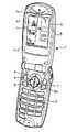
【発明の実施の形態】図1は本発明の一実施形態を示す携帯情報端末の斜視図である。携帯電話機能を備える携帯情報端末1は、方位磁石2を備え方位が分るようになっている。本例はヒンジによって折畳める携帯情報端末で操作キーを配置した下部筐体3と表示部4を配置した上部筐体5は結合部のヒンジ機構によって二つ折りに折畳める。表示部4には詳細地図が表示される地図表示領域4aとその外側の情報表示領域4bが設けられている。
【0006】
方向キー6は、文字入力の際にはカーソルを移動させるものであるが、地図表示の場合には、その操作によって東西南北4方向に隣接する地図に表示を切り替えることができる。符号7はエンターキー(決定キー)で、表面が透明の押圧板8でキー内に方位磁石2を内蔵した構造を有している。表示領域4aに表示される地図は、その上側が“北”となるようにデータが統一されており、方位磁石2の針が真上を向くとき表示された地図の向きと実際の携帯情報端末の向きが一致することになる。情報表示領域4bには、符号4b−1で示す表示領域4aの四方から囲む方向表示領域が有り、部分的に点灯しランドマークの方向を示している。図1はランドマークが、現在位置に対し略真北の方向に位置していることが表示されている。
【0007】
また、符号4b−2は識別情報表示領域で、方向表示領域4b−1で方向が示されているランドマークについてその名称や住所、現在位置として確定入力の操作がされた通過目標地点の住所や名称、さらにその次の通過目標地点の住所や名称の識別情報などが表示される。使用者は目的地に向かう際に点線で示すルートに沿って移動するが、その際、ランドマークを手がかりとし、次の通過目標地点を目指すことで目的地にすみやかにたどり着くことが可能となる。地図上の通過目標地点の順番は、出発地点を1番目として、目的地点まで連続番号が付されている。
【0008】
図1の図示例は、出発地点が現在位置となっている状態で、現在位置を星印で示し、2番目の通過目標地点(B公園)が次の通過目標地点となる。次の通過目標地点は、図1の図示例では、その位置を四角で囲んでいるが、さらに反転表示する等して次の通過目標地点であることを地図上に示す。操作キーにはテンキーと#の各キーが備わっていて、これらのキーを使うことでナビゲーションを行うことができる。すなわち、2番目の通過目標地点であるB公園に到着した際に、地図上に表示されている番号に基づいて#2と入力すると、2番目の通過目標地点が現在位置として確定されたこととなり、識別情報表示領域4b−2には現在位置として2番目のB公園の住所や名称と、次の通過目標地点となる3番目のA駅の住所や名称と、ランドマークの名称や住所が表示される。方向表示領域4b−1では2番目のB公園に対するランドマークの方向にあたる部分が点灯することになる。なお、#3と入力した場合には、表示地図においては最後の順番となるので地図が次の地図(3番目のA駅を含んだ詳細地図)に自動的に切り替わるように設定できる。
【0009】
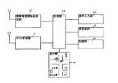
図2は、本一実施形態の携帯情報端末のブロック図である。携帯電話無線送受信部10は携帯電話システムの無線基地局と無線接続する。制御部20はそのための通信プロトコル、チャネルフォーマット、データフォーマットに対応し、端末全体の制御を行う。GPS受信機11はGPS衛星の電波を受信し、制御部20は受信機11からの復調信号に基づいて位置情報(緯度、経度、高度)を検出するが、本発明においては必要ないものである。
【0010】
操作入力部12はキー操作部で、方向キー6、エンターキー7の他、テンキー、#キー等の操作キーから構成される。送受話部13は音声コーデック、マイク、スピーカ等の音声入出力変換手段から構成される。記憶部14は電話帳、メールアドレス帳等の電話端末機能や電子メール機能に係わるプログラムやデータを記憶し、スケジューラー機能等のPDA機能に係わるプログラムやデータを記憶し、さらに、ナビゲーションソフト及びダウンロード情報(地図情報、ルート情報、ランドマーク情報)のナビゲーション機能に係わるプログラム及びデータを記憶する。
【0011】
この携帯情報端末1は携帯電話無線送受信部10を介してインターネットに接続し、地図検索サイトにて現在地から目的地へのルート検索を行い、周辺地図をダウンロードし、地図表示を行う。
【0012】
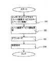
図3はルート検索サービスから地図表示までの全体の流れを示すフローである。携帯情報端末1の携帯電話機能によってインターネットにアクセス後、ルート検索サービスホームページに接続(101)して、現在位置及び目的地を入力してサービス開始を要求(102)を行うとデータのダウンロードがされる(103)。
【0013】
携帯情報端末1では制御部20が、ダウンロードデータを記憶部14に記憶し、地図情報、ルート情報及びランドマーク情報に基づく表示を行う(104)。この表示では、操作手段(テンキー及び#キー)を使って通過目標地点の順番を入力(#1、#2、〜)する操作を行うことで、後述するように各通過目標地点におけるランドマーク方向の計算及び点灯表示の処理、表示中の最後の通過目標地点に到達した際には次の頁番号の地図への表示切替えの処理、識別情報表示処理などを行う。
【0014】
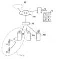
図4は、ルート検索サービスを説明するシステムの概念図である。携帯電話網80が接続するインターネットにルート検索サービスを行うサーバー70とデータベース75が接続している例を図示している。
【0015】
このデータベース75はルートデータベース75−1、ランドマークデータベース75−2、地図データベース75−3を備えている。携帯電話網80には携帯電話システムの制御局40が、さらに無線基地局30、30A、30Bが接続されている例である。さらに図は無線基地局30のゾーンに携帯情報端末A、Bが存在し無線基地局30を介してネットワークに接続している例である。本例では携帯情報端末Aを図1に示す携帯情報端末1とみなす。また、符号60は携帯電話網に接続する他のネットワークを示している。
【0016】
このようなシステムを一例として、例えば携帯情報端末Aが無線基地局30を介してサーバ70にアクセスした場合、携帯情報端末Aの使用者が現在位置を入力し、目的地を入力し、ルート検索開始を要求することでサーバ70がルートデータベース75−1を用いてルート検索を実行する。ルート検索の結果が出ると、ランドマークデータベース75−2を検索し、ルート途中に存在する施設等若しくは遠方ではあってもルート上から見える高層ビル等のランドマークを検索し、ルート情報とランドマーク情報が求まると、地図データベース75−3からルート情報に対応する広域地図及び詳細地図が読み出され、それぞれにルートを示す点線を図示する編集を加える。
【0017】
サーバ70は、完成した地図情報と、検索したルート情報及びランドマーク情報を携帯情報端末Aにダウンロードする。なお、図1に示す携帯情報端末1の場合、GPS受信機11により制御部20は現在位置情報(経度、緯度、高度)を取得することが可能なので、このGPS受信機11を用いた位置検出手段の出力をサーバー70への現在位置入力にしてもよい。
【0018】
なお、広域地図は、現在地から目的地までのルート全体を網羅する1枚の地図である。詳細地図は、ルート上の、道路、交差点、沿道の施設等を詳細に図示したもので、現在地から目的地までを1枚もしくは複数枚の地図によって網羅する。
図5はダウンロード情報のデータフォーマットを示す。(a)は地図情報のフォーマットである。ヘッダー部分は、この画像データの地図が広域地図であるか詳細地図であるかを示す“地図種別”、ダウンロードする地図の“全頁数”、この地図の“頁番号”、この地図の範囲を示す“最大経度”、“最小経度”、“最大緯度”、“最小緯度”、この地図がカバーするエリアの名称の各情報で構成される。そしてヘッダー部分の後にこの地図の画像データが続く。
【0019】
図5(b)はランドマーク情報のフォーマットで、この情報の“識別番号”と、ランドマークの位置情報である“経度”と“緯度”と、ランドマークの“名称”及び“住所”の識別情報からなる。
【0020】
図5(c)はルート情報のフォーマットであり、現在地から目的地に至る通過目標地点の情報で、現在地点から目的地点の各通過目標地点についてそれぞれこのフォーマットで情報がまとめられている。情報を含んでいる。情報の内訳は、その地点が位置する“地図種別”と“頁番号”がある。この“地図種別”と“頁番号”は図5(a)の“地図種別”と“頁番号”に対応する。
【0021】
さらに、ルート情報にはルート上における全通過目標地点の数である“全通過地点数”とこの情報の順番情報である“地点番号”、その通過目標地点の“経度”、“緯度”、その通過目標地点から見えるランドマーク情報を特定するための“識別番号1”と“識別番号2”、そしてその通過目標地点の“名称”と“住所”からなる。識別番号1と識別番号2はそれぞれ図5(b)のランドマーク情報の“識別番号”に対応している。
【0022】
サーバー70からダウンロードしたデータを記憶した携帯情報端末1は、地図表示領域4aに地図表示を行い、現在位置(出発地点)に対応するランドマークの方向を方向表示領域4b−1に、ランドマークの名称及び住所と現在位置の住所及び名称と次の通過目標地点(ただし、詳細地図の場合。広域地図の場合は、目的地としてもよい)の住所及び名称を識別情報表示領域4b−2に表示する。
【0023】
方向は、ランドマーク情報の“経度”と“緯度”とルート情報の“経度”と“緯度”から各通過目標地点に対するランドマークの方角が求まるので、北を上にした地図表示領域4aの表示地図の向きに合せて方向表示領域4b−1の対応部分を点灯表示させる。
【0024】
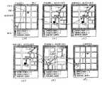
図6は地図表示画面の遷移を示す例で、制御部20の動作を説明するものである。(a)は広域地図表示で、地図表示領域4aに現在位置から目的地のルートが点線で示される。(b)〜(e)は詳細地図1〜4の表示で同様にルートが点線で示される。(f)は再び広域地図表示である。広域地図と詳細地図の表示切替えは、操作入力部12の所定操作で行なえる。各図において方向表示領域4b−1には現在位置に対するランドマークL1の方向に一致する部分が点灯している。
【0025】
図6の各図において識別情報表示領域4b−2には、“現”で示す現在位置情報、“目”で示す最後の通過目標地点としてルート情報に含まれている目的地情報または“次”で示す次の通過目標地点情報、さらに“L1”で示すランドマーク情報を表示する。識別情報表示領域4b−2には、現在位置情報、通過目標地点情報として住所表示もしくは名称表示の表示切替えを所定操作で行うことができる。
【0026】
ランドマーク情報についても住所表示と名称表示の表示切替えを所定操作で行うことができる。各図において点線の円で示すマーキングは通過目標地点であって特に現在位置として示し、実線の円で示すマーキングは各通過目標地点であり、これらは制御部20が、図5(a)の地図情報によって地図の範囲(最大経度、最大緯度、最小経度、最小緯度)が分かっているので、図5(c)の各通過目標地点のルート情報の経度と緯度から、各通過目標地点の表示部4aにおける表示位置を求めて行っている。
【0027】
図6(b)は詳細地図の1頁目で、通過目標地点1(=現在位置)、通過目標地点2、3、4が表示されている。現在位置は点線の円で点滅表示され、その他の通過目標地点は実線の円でマーキングされる。この状態から使用者は、目視可能なランドマークL1を手がかりに、次の通過目標地点2に進み、表示されている“次”の住所に辿り着いたならば“#2”を入力すると図6(c)の表示となる。
【0028】
図6(c)では通過目標地点2の位置が点線の円を点滅表示されている。同様にして通過目標地点3に辿り着いたならば“#3”を入力し、通過目標地点4に辿り着いたならば“#4”を入力する。
【0029】
図6(d)は“#4”を入力し、通過目標地点4を点線の円で点滅表示させている状態で、本例の場合には、頁番号1の詳細地図が表示されているが、制御部20はルート情報において4番目の通過目標地点が地点番号として最大なので1頁目の最後の通過目標地点と判断しているので、この状態でエンターキー7を押すと図6(e)のように詳細地図の2頁目に表示が切り替わる。
【0030】
なお、制御部20はルート情報において頁番号1の詳細地図では4番目の通過目標地点が1頁目の最後の通過目標地点と判断しているので、4番目の通過目標地点を選択する“#4”が入力された場合、図6(e)の頁番号2の詳細地図に自動的に表示切替えすることも、予め表示設定しておくことで可能である。
【0031】
図6(e)は頁番号2の詳細地図であるが、この表示においては地点番号7が最後の通過目標地点と判断されるので、“#7”が入力されると次ぎの頁番号3の詳細地図に表示が自動切替えできる。以上の表示制御は、目的地の含まれる最後の頁番号の表示がされるまで、同様である。
なお、図6(f)は、広域地図に表示切替えした例で、所定の操作によって広域地図と詳細地図の表示切替えを行なえることは前述した通りであるが、同図に示すように広域地図を表示することによりルート上のおおよその位置を知ることが可能である。
【0032】
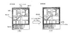
図7はランドマーク方向及びランドマーク識別情報の表示を他のものに表示切替えする例を説明する画面遷移図で、4番目の通過目標地点に現在位置する場合のランドマークの表示例を示す。同図(a)はランドマークL1が北北東の方角に位置することが方向表示領域4b−1の点灯で識別でき、それが「都築清掃工場煙突」であることを情報表示領域4b−2の表示で識別できる。所定のキー操作により表示切替えを行い、表示切替えされた同図(b)はランドマークL2がほぼ東の方角に位置し、それが「京セラ横浜事業所」施設であることを識別できる。
【0033】
図7(a)は、はじめに図5(c)のルート情報の識別番号1で特定される図5(b)のランドマーク情報(本例ではL1)を表示するようデフォルト設定さによる表示例であるが、図7(b)は操作入力部12の所定キー操作がされることによって識別番号2のランドマーク情報(本例ではL2)に切替えてL2のランドマーク方向とその名称が表示されたものである。
【0034】
以上のように、本発明によればGPS受信機等の位置検出手段を用いることなくナビゲーションできることを示した。
【0035】
なお、上記実施形態においては、次の通過目標地点の住所または名称を表示することで地図上の進むべき道を使用者に考えさせるようになっているが、さらに進行方向を分り易くするために図5(c)のルート情報のフォーマットに次の通過目標地点への進行方向を指示するメッセージ情報の項目を加えてもよい。メッセージ情報としては、例えば、「郵便局方向へ直進」とか、「郵便局右方向へ進む」とか、「〇×銀行の斜め右方向へ進む」などである。ルートデータベース75−1にこのメッセージ情報を記憶させておき、サーバー70が検索結果に基づいてルート情報中に、このメッセージ情報を加え、地図情報及びランドマーク情報とともに携帯情報端末にダウンロードする。携帯情報端末においては、操作手段により順番情報が入力され通過目標地点(ルート情報)が確定された際に、識別情報表示領域4b−2にその確定されたルート情報中のメッセージ情報を表示することで、ナビゲーション機能がさらに使い易いものになる。
【0036】
【発明の効果】本発明によれば、地図データを記憶し、地図表示機能を有する携帯情報端末において、複数の通過目標地点の識別情報、位置情報及び順番情報と、ランドマークの識別情報及び位置情報とを記憶する記憶手段と、操作手段と、前記地図表示機能の処理を行い、前記操作手段による前記順番情報の入力によって通過目標地点の一つが選択されると、選択された通過目標地点に対するランドマークの位置する方向を表示し、該通過目標地点に対して次の順番情報を有する通過目標地点の識別情報を表示する、処理を行う制御手段を具備することにより、少なくとも上記構成を備えることによって、位置検出手段を使うことなく携帯情報端末における実用上十分なナビゲーション機能を実現することができる。
【0037】
また、前記操作手段によって前記順番情報の一つが選択されると、前記制御手段が、さらに選択された通過目標地点の識別情報を表示し、前記ランドマークの識別情報を表示する、処理を行うことにより、選択された通過目標地点及びランドマークの識別情報を表示により確認でき、選択された通過目標地点に対するランドマークの方向を目視により確認する際に間違いを起こし難くなる。
【0038】
また、前記ランドマークの識別情報及び位置情報が、複数のランドマークについて前記記憶手段に記憶されており、前記操作手段によって前記複数のランドマークから任意のものを選択可能とされ、前記制御手段が選択されたランドマークについて前記方向の表示を行う、処理を行うことにより、複数のランドマークに基づいてその方向を確認でき、より間違いを起こし難くなる。
【0039】
また、前記複数の通過目標地点における各メッセージ情報を前記記憶手段に記憶させ、前記操作手段によって通過目標地点の一つが選択されると、前記制御手段が、選択された通過目標地点におけるメッセージ情報を表示する、処理を行うことにより、少なくともランドマークの方向及び次の通過目標地点の識別情報にメッセージ情報の表示が加わるので、より迅速に次の通過目標地点に到達することが可能となる。
【図面の簡単な説明】
【図1】本発明の一実施形態を示す携帯情報端末の斜視図。
【図2】本発明の一実施形態を示す携帯情報端末のブロック図
【図3】本発明の一実施形態を示すルート検索サービスから地図表示までの全体の流れを示すフロー。
【図4】本発明の一実施形態を示すルート検索サービスを説明するシステムの概念図。
【図5】本発明の一実施形態を示す、(a)〜(c)はダウンロード情報のデータフォーマット。
【図6】本発明の一実施形態を示す、(a)〜(f)は地図表示画面の遷移図。
【図7】本発明の一実施形態を示す、(a)、(b)はランドマーク方向およびランドマーク識別情報の表示を他のランドマークのものに表示切替えする例を説明する画面遷移図。
【符号の説明】
1 携帯情報端末
3 操作キーを配した下部筐体
4 表示部
4a 地図表示領域
4b−1 方向表示領域
4b−2 識別情報表示領域[0001]
[0001] The present invention relates to a portable information terminal having a map display function, and more particularly to a navigation function.
[0002]
2. Description of the Related Art A portable telephone is a typical portable information terminal, and a portable telephone service includes a map information distribution service. In this service, when a current position and a destination are input from a mobile phone, map information of the surrounding area is downloaded from the database on the network side to the mobile phone. The mobile phone has a map display function of displaying downloaded and stored map information.
On the other hand, the car navigation function has been advanced in automobiles, and it has a function of receiving GPS satellite signals and detecting its own location information (longitude, latitude, altitude), and displays the detected current location information. An instruction of a traveling direction is performed in real time based on current position information detected as needed.
[0003]
However, it is extremely difficult to realize a navigation function similar to a car navigation function in a portable information terminal such as a cellular phone. This is because GPS signals are difficult to receive in areas with poor visibility due to buildings and terrain due to buildings and the like, and the accuracy drops due to reflections and the like, so complicated calculations such as correction processing using correction information are required. Since it is extremely difficult for information terminals to calculate and correct the distance direction, it is very difficult to implement a navigation function that instructs the direction of travel in real time based on position information detected at any time, similar to car navigation. Extremely difficult.
An object of the present invention is to realize a navigation function that can be realized and is functionally sufficient in a portable information terminal without using a position detection function in order to cope with such a situation.
[0004]
According to the present invention, there is provided a portable information terminal which stores map data and has a map display function, comprising: identification information, position information, and order information of a plurality of passing target points; A storage unit for storing landmark identification information and position information, an operation unit, and a process of the map display function. When one of the order information is selected by the operation unit, the selected order information is stored. At least control means for displaying the direction in which the landmark is located with respect to the passing target point, and displaying the identification information of the passing target point having the next order information with respect to the order information is provided.
[0005]
FIG. 1 is a perspective view of a portable information terminal showing one embodiment of the present invention. A
[0006]
The
[0007]
[0008]
In the illustrated example of FIG. 1, the current position is indicated by an asterisk in a state in which the departure point is the current position, and the second pass target point (Park B) is the next pass target point. In the example shown in FIG. 1, the position of the next pass target point is surrounded by a square. The operation keys include numeric keys and # keys, and navigation can be performed by using these keys. That is, when arriving at Park B, which is the second pass target point, and entering # 2 based on the number displayed on the map, the second pass target point is determined as the current position. In the identification
[0009]
FIG. 2 is a block diagram of the portable information terminal according to the embodiment. The mobile phone wireless transmission /
[0010]
The operation input unit 12 is a key operation unit and includes operation keys such as a ten key and a # key in addition to the
[0011]
The
[0012]
FIG. 3 is a flowchart showing the entire flow from the route search service to the map display. After accessing the Internet by the mobile phone function of the
[0013]
In the
[0014]
FIG. 4 is a conceptual diagram of a system for explaining a route search service. An example is shown in which a
[0015]
The
[0016]
As an example of such a system, for example, when the portable information terminal A accesses the
[0017]
The
[0018]
The wide area map is a single map covering the entire route from the current location to the destination. The detailed map is a detailed illustration of roads, intersections, roadside facilities, and the like on the route, and covers one or more maps from the current location to the destination.
FIG. 5 shows a data format of the download information. (A) is a format of map information. The header part indicates “map type” indicating whether the map of this image data is a wide area map or a detailed map, “the total number of pages” of the map to be downloaded, “page number” of this map, and the range of this map. The information includes “maximum longitude”, “minimum longitude”, “maximum latitude”, “minimum latitude”, and the name of the area covered by this map. The image data of this map follows the header portion.
[0019]
FIG. 5B shows a format of the landmark information. The “identification number” of this information, “longitude” and “latitude” as the position information of the landmark, and the identification of the “name” and “address” of the landmark are shown. Consists of information.
[0020]
FIG. 5C shows the format of the route information, which is information on target passage points from the current location to the destination. The information is collected in this format for each target passage point from the current location to the destination. Contains information. The breakdown of the information includes “map type” and “page number” where the point is located. The “map type” and “page number” correspond to the “map type” and “page number” in FIG.
[0021]
Further, the route information includes “the total number of passing points” which is the number of all passing target points on the route, “point number” which is the order information of this information, “longitude” and “latitude” of the passing target point, and the like. It consists of “
[0022]
The
[0023]
As for the direction, since the direction of the landmark with respect to each passing target point is determined from the "longitude" and "latitude" of the landmark information and the "longitude" and "latitude" of the route information, the map display area 4a with the north facing upward is displayed. The corresponding portion of the
[0024]
FIG. 6 is an example showing the transition of the map display screen, and explains the operation of the
[0025]
In each of FIGS. 6A and 6B, in the identification
[0026]
For landmark information, display switching between address display and name display can be performed by a predetermined operation. In each of the figures, the markings indicated by the dotted circles are the passing target points and are particularly indicated as the current position, and the markings indicated by the solid circles are the respective passing target points, which are controlled by the
[0027]
FIG. 6B shows the first page of the detailed map, in which a passing target point 1 (= current position) and passing target points 2, 3, and 4 are displayed. The current position is displayed as a blinking circle with a dotted line, and the other target points are marked with a solid circle. From this state, the user proceeds to the next
[0028]
In FIG. 6C, the position of the passing
[0029]
FIG. 6D shows a state in which “# 4” is input and the passing target point 4 is displayed in a blinking circle with a dotted line. In this example, a detailed map of
[0030]
In the route information, the
[0031]
FIG. 6 (e) is a detailed map of
FIG. 6F shows an example in which the display is switched to the wide area map, and the display switching between the wide area map and the detailed map can be performed by a predetermined operation as described above, but as shown in FIG. By displaying, it is possible to know the approximate position on the route.
[0032]
FIG. 7 is a screen transition diagram for explaining an example in which the display of the landmark direction and the landmark identification information is switched to another display, and shows a display example of the landmark when the current position is at the fourth pass target point. In FIG. 9A, the lighting of the
[0033]
FIG. 7A is a display example in which default setting is first made to display the landmark information (L1 in this example) of FIG. 5B specified by the
[0034]
As described above, it has been shown that navigation can be performed according to the present invention without using a position detecting unit such as a GPS receiver.
[0035]
In the above-described embodiment, the address or name of the next target point is displayed so that the user can think of the road to go on the map. An item of message information indicating the traveling direction to the next destination point may be added to the format of the route information in FIG. The message information includes, for example, "go straight to the post office", "go right to the post office", "go diagonally right of the bank". The message information is stored in the route database 75-1, and the
[0036]
According to the present invention, in a portable information terminal which stores map data and has a map display function, identification information, position information and order information of a plurality of target points, landmark identification information and positions are provided. A storage unit for storing information, an operation unit, and a process of the map display function. When one of the passage target points is selected by inputting the order information by the operation unit, Displaying the direction in which the landmark is located, and displaying the identification information of the pass target point having the next order information with respect to the pass target point; Thereby, a practically sufficient navigation function in the portable information terminal can be realized without using the position detecting means.
[0037]
Further, when one of the order information is selected by the operation means, the control means displays the identification information of the further selected pass target point, and displays the identification information of the landmark. Thereby, the identification information of the selected pass target point and the landmark can be confirmed by display, and it is difficult to make an error when visually confirming the direction of the landmark with respect to the selected pass target point.
[0038]
Further, identification information and position information of the landmarks are stored in the storage unit for a plurality of landmarks, and any one of the plurality of landmarks can be selected by the operating unit, and the control unit By performing the process of displaying the direction of the selected landmark, the direction can be confirmed based on a plurality of landmarks, and errors are less likely to occur.
[0039]
In addition, each message information at the plurality of passing target points is stored in the storage unit, and when one of the passing target points is selected by the operation unit, the control unit transmits the message information at the selected passing target point. By performing the display and the processing, the display of the message information is added to at least the direction of the landmark and the identification information of the next target point, so that it is possible to reach the next target point more quickly.
[Brief description of the drawings]
FIG. 1 is a perspective view of a portable information terminal showing one embodiment of the present invention.
FIG. 2 is a block diagram of a portable information terminal showing one embodiment of the present invention. FIG. 3 is a flow showing an entire flow from a route search service to a map display showing one embodiment of the present invention.
FIG. 4 is a conceptual diagram of a system for explaining a route search service according to an embodiment of the present invention.
FIGS. 5A to 5C show a data format of download information according to an embodiment of the present invention.
FIGS. 6A to 6F are transition diagrams of a map display screen, showing one embodiment of the present invention.
FIGS. 7A and 7B are screen transition diagrams illustrating an example of switching the display of landmark direction and landmark identification information to that of another landmark according to an embodiment of the present invention.
[Explanation of symbols]
Claims (5)
Translated fromJapanesePriority Applications (1)
| Application Number | Priority Date | Filing Date | Title |
|---|---|---|---|
| JP2002186850AJP4325905B2 (en) | 2002-06-26 | 2002-06-26 | Portable information terminal |
Applications Claiming Priority (1)
| Application Number | Priority Date | Filing Date | Title |
|---|---|---|---|
| JP2002186850AJP4325905B2 (en) | 2002-06-26 | 2002-06-26 | Portable information terminal |
Publications (2)
| Publication Number | Publication Date |
|---|---|
| JP2004028837Atrue JP2004028837A (en) | 2004-01-29 |
| JP4325905B2 JP4325905B2 (en) | 2009-09-02 |
Family
ID=31182080
Family Applications (1)
| Application Number | Title | Priority Date | Filing Date |
|---|---|---|---|
| JP2002186850AExpired - Fee RelatedJP4325905B2 (en) | 2002-06-26 | 2002-06-26 | Portable information terminal |
Country Status (1)
| Country | Link |
|---|---|
| JP (1) | JP4325905B2 (en) |
Cited By (10)
| Publication number | Priority date | Publication date | Assignee | Title |
|---|---|---|---|---|
| WO2005095890A1 (en)* | 2004-03-31 | 2005-10-13 | Kyocera Corporation | Direction computing device and error correcting method |
| JP2006168437A (en)* | 2004-12-14 | 2006-06-29 | Navitime Japan Co Ltd | Navigation system, route search server and terminal device |
| JP2007114797A (en)* | 2004-03-17 | 2007-05-10 | Nec Corp | Map display method, map display system, mobile terminal, and program |
| JP2009510455A (en)* | 2005-09-30 | 2009-03-12 | オートデスク,インコーポレイテッド | Landmark enhanced road guidance |
| WO2009078106A1 (en)* | 2007-12-19 | 2009-06-25 | Pioneer Corporation | Image display, image display method, and program for image display |
| WO2009078079A1 (en)* | 2007-12-14 | 2009-06-25 | Pioneer Corporation | Navigation system, portable terminal, server device, portable terminal program, server device program, and guidance method |
| US7814671B2 (en) | 2004-03-31 | 2010-10-19 | Kyocera Corporation | Mobile bearing calculator and bearing correction method |
| US7912640B2 (en) | 2004-03-31 | 2011-03-22 | Kyocera Corporation | Mobile map display apparatus, map display system and map display method |
| US8155884B2 (en) | 2004-03-31 | 2012-04-10 | Kyocera Corporation | Bearing display apparatus and bearing display method |
| US8725406B2 (en) | 2004-06-24 | 2014-05-13 | Kyocera Corporation | Mobile communication terminal and map display system |
- 2002
- 2002-06-26JPJP2002186850Apatent/JP4325905B2/ennot_activeExpired - Fee Related
Cited By (13)
| Publication number | Priority date | Publication date | Assignee | Title |
|---|---|---|---|---|
| JP2007114797A (en)* | 2004-03-17 | 2007-05-10 | Nec Corp | Map display method, map display system, mobile terminal, and program |
| US7937217B2 (en) | 2004-03-31 | 2011-05-03 | Kyocera Corporation | Bearing calculator and error correction method |
| US7769539B2 (en) | 2004-03-31 | 2010-08-03 | Kyocera Corporation | Bearing calculator and error correction method |
| US7814671B2 (en) | 2004-03-31 | 2010-10-19 | Kyocera Corporation | Mobile bearing calculator and bearing correction method |
| US7912640B2 (en) | 2004-03-31 | 2011-03-22 | Kyocera Corporation | Mobile map display apparatus, map display system and map display method |
| WO2005095890A1 (en)* | 2004-03-31 | 2005-10-13 | Kyocera Corporation | Direction computing device and error correcting method |
| US7941268B2 (en) | 2004-03-31 | 2011-05-10 | Kyocera Corporation | Bearing calculator and error correction method |
| US8155884B2 (en) | 2004-03-31 | 2012-04-10 | Kyocera Corporation | Bearing display apparatus and bearing display method |
| US8725406B2 (en) | 2004-06-24 | 2014-05-13 | Kyocera Corporation | Mobile communication terminal and map display system |
| JP2006168437A (en)* | 2004-12-14 | 2006-06-29 | Navitime Japan Co Ltd | Navigation system, route search server and terminal device |
| JP2009510455A (en)* | 2005-09-30 | 2009-03-12 | オートデスク,インコーポレイテッド | Landmark enhanced road guidance |
| WO2009078079A1 (en)* | 2007-12-14 | 2009-06-25 | Pioneer Corporation | Navigation system, portable terminal, server device, portable terminal program, server device program, and guidance method |
| WO2009078106A1 (en)* | 2007-12-19 | 2009-06-25 | Pioneer Corporation | Image display, image display method, and program for image display |
Also Published As
| Publication number | Publication date |
|---|---|
| JP4325905B2 (en) | 2009-09-02 |
Similar Documents
| Publication | Publication Date | Title |
|---|---|---|
| JP3791249B2 (en) | Mobile device | |
| EP1063625B1 (en) | Traffic information system for a vehicle | |
| CN101925799B (en) | Navigation device, system and method with air search module | |
| CN101578501B (en) | Navigation device and method | |
| US7957895B2 (en) | Navigation device and method | |
| EP2646781B1 (en) | Navigation methods and systems | |
| EP1469287A2 (en) | Device for map information processing and position display | |
| KR20100005152A (en) | Map display system, map display, and map display method | |
| WO2004036146A1 (en) | Navigation apparatus and server apparatus | |
| CN102027319A (en) | Navigation device and method | |
| CN101903747A (en) | Navigation device & method | |
| JP2012514188A (en) | Navigation apparatus and method | |
| JP4325905B2 (en) | Portable information terminal | |
| CN102037329A (en) | Navigation device & method | |
| JP2006162270A (en) | Map update system, navigation device, distribution device | |
| JP2015059769A (en) | Terminal and control program | |
| ES2499066T3 (en) | Enhanced device and navigation method | |
| JP3906245B2 (en) | Navigation system | |
| JP2004317952A (en) | Point display device | |
| JP4405449B2 (en) | Navigation system, map display device, and map display method | |
| JP2004028854A (en) | Portable terminal, positional information server, and user guiding system | |
| JP2004340854A (en) | Map information distribution system | |
| KR101161764B1 (en) | apparatus, method, and system for providing information relevant to POI | |
| JP4228759B2 (en) | Information terminal equipment | |
| KR101117782B1 (en) | mobile phone with POI display function, system using the same |
Legal Events
| Date | Code | Title | Description |
|---|---|---|---|
| A621 | Written request for application examination | Free format text:JAPANESE INTERMEDIATE CODE: A621 Effective date:20041115 | |
| A131 | Notification of reasons for refusal | Free format text:JAPANESE INTERMEDIATE CODE: A131 Effective date:20061003 | |
| A521 | Written amendment | Free format text:JAPANESE INTERMEDIATE CODE: A523 Effective date:20061201 | |
| A02 | Decision of refusal | Free format text:JAPANESE INTERMEDIATE CODE: A02 Effective date:20070605 | |
| A521 | Written amendment | Free format text:JAPANESE INTERMEDIATE CODE: A523 Effective date:20070806 | |
| A911 | Transfer to examiner for re-examination before appeal (zenchi) | Free format text:JAPANESE INTERMEDIATE CODE: A911 Effective date:20070810 | |
| A912 | Re-examination (zenchi) completed and case transferred to appeal board | Free format text:JAPANESE INTERMEDIATE CODE: A912 Effective date:20071005 | |
| A521 | Written amendment | Free format text:JAPANESE INTERMEDIATE CODE: A523 Effective date:20090414 | |
| A01 | Written decision to grant a patent or to grant a registration (utility model) | Free format text:JAPANESE INTERMEDIATE CODE: A01 | |
| A61 | First payment of annual fees (during grant procedure) | Free format text:JAPANESE INTERMEDIATE CODE: A61 Effective date:20090605 | |
| FPAY | Renewal fee payment (event date is renewal date of database) | Free format text:PAYMENT UNTIL: 20120619 Year of fee payment:3 | |
| R150 | Certificate of patent or registration of utility model | Free format text:JAPANESE INTERMEDIATE CODE: R150 | |
| FPAY | Renewal fee payment (event date is renewal date of database) | Free format text:PAYMENT UNTIL: 20120619 Year of fee payment:3 | |
| FPAY | Renewal fee payment (event date is renewal date of database) | Free format text:PAYMENT UNTIL: 20130619 Year of fee payment:4 | |
| LAPS | Cancellation because of no payment of annual fees |