JP2004021557A - Program, information processing method, information processing device, and storage device - Google Patents
Program, information processing method, information processing device, and storage deviceDownload PDFInfo
- Publication number
- JP2004021557A JP2004021557AJP2002174945AJP2002174945AJP2004021557AJP 2004021557 AJP2004021557 AJP 2004021557AJP 2002174945 AJP2002174945 AJP 2002174945AJP 2002174945 AJP2002174945 AJP 2002174945AJP 2004021557 AJP2004021557 AJP 2004021557A
- Authority
- JP
- Japan
- Prior art keywords
- access
- efficiency
- information
- host
- storage area
- Prior art date
- Legal status (The legal status is an assumption and is not a legal conclusion. Google has not performed a legal analysis and makes no representation as to the accuracy of the status listed.)
- Pending
Links
Images


Classifications
- G—PHYSICS
- G06—COMPUTING OR CALCULATING; COUNTING
- G06F—ELECTRIC DIGITAL DATA PROCESSING
- G06F3/00—Input arrangements for transferring data to be processed into a form capable of being handled by the computer; Output arrangements for transferring data from processing unit to output unit, e.g. interface arrangements
- G06F3/06—Digital input from, or digital output to, record carriers, e.g. RAID, emulated record carriers or networked record carriers
- G06F3/0601—Interfaces specially adapted for storage systems
- G06F3/0628—Interfaces specially adapted for storage systems making use of a particular technique
- G06F3/0662—Virtualisation aspects
- G06F3/0665—Virtualisation aspects at area level, e.g. provisioning of virtual or logical volumes
- G—PHYSICS
- G06—COMPUTING OR CALCULATING; COUNTING
- G06F—ELECTRIC DIGITAL DATA PROCESSING
- G06F12/00—Accessing, addressing or allocating within memory systems or architectures
- G06F12/02—Addressing or allocation; Relocation
- G06F12/08—Addressing or allocation; Relocation in hierarchically structured memory systems, e.g. virtual memory systems
- G—PHYSICS
- G06—COMPUTING OR CALCULATING; COUNTING
- G06F—ELECTRIC DIGITAL DATA PROCESSING
- G06F3/00—Input arrangements for transferring data to be processed into a form capable of being handled by the computer; Output arrangements for transferring data from processing unit to output unit, e.g. interface arrangements
- G06F3/06—Digital input from, or digital output to, record carriers, e.g. RAID, emulated record carriers or networked record carriers
- G06F3/0601—Interfaces specially adapted for storage systems
- G06F3/0602—Interfaces specially adapted for storage systems specifically adapted to achieve a particular effect
- G06F3/061—Improving I/O performance
- G—PHYSICS
- G06—COMPUTING OR CALCULATING; COUNTING
- G06F—ELECTRIC DIGITAL DATA PROCESSING
- G06F3/00—Input arrangements for transferring data to be processed into a form capable of being handled by the computer; Output arrangements for transferring data from processing unit to output unit, e.g. interface arrangements
- G06F3/06—Digital input from, or digital output to, record carriers, e.g. RAID, emulated record carriers or networked record carriers
- G06F3/0601—Interfaces specially adapted for storage systems
- G06F3/0628—Interfaces specially adapted for storage systems making use of a particular technique
- G06F3/0646—Horizontal data movement in storage systems, i.e. moving data in between storage devices or systems
- G06F3/0647—Migration mechanisms
- G—PHYSICS
- G06—COMPUTING OR CALCULATING; COUNTING
- G06F—ELECTRIC DIGITAL DATA PROCESSING
- G06F3/00—Input arrangements for transferring data to be processed into a form capable of being handled by the computer; Output arrangements for transferring data from processing unit to output unit, e.g. interface arrangements
- G06F3/06—Digital input from, or digital output to, record carriers, e.g. RAID, emulated record carriers or networked record carriers
- G06F3/0601—Interfaces specially adapted for storage systems
- G06F3/0628—Interfaces specially adapted for storage systems making use of a particular technique
- G06F3/0653—Monitoring storage devices or systems
- G—PHYSICS
- G06—COMPUTING OR CALCULATING; COUNTING
- G06F—ELECTRIC DIGITAL DATA PROCESSING
- G06F3/00—Input arrangements for transferring data to be processed into a form capable of being handled by the computer; Output arrangements for transferring data from processing unit to output unit, e.g. interface arrangements
- G06F3/06—Digital input from, or digital output to, record carriers, e.g. RAID, emulated record carriers or networked record carriers
- G06F3/0601—Interfaces specially adapted for storage systems
- G06F3/0668—Interfaces specially adapted for storage systems adopting a particular infrastructure
- G06F3/067—Distributed or networked storage systems, e.g. storage area networks [SAN], network attached storage [NAS]
- Y—GENERAL TAGGING OF NEW TECHNOLOGICAL DEVELOPMENTS; GENERAL TAGGING OF CROSS-SECTIONAL TECHNOLOGIES SPANNING OVER SEVERAL SECTIONS OF THE IPC; TECHNICAL SUBJECTS COVERED BY FORMER USPC CROSS-REFERENCE ART COLLECTIONS [XRACs] AND DIGESTS
- Y10—TECHNICAL SUBJECTS COVERED BY FORMER USPC
- Y10S—TECHNICAL SUBJECTS COVERED BY FORMER USPC CROSS-REFERENCE ART COLLECTIONS [XRACs] AND DIGESTS
- Y10S707/00—Data processing: database and file management or data structures
- Y10S707/953—Organization of data
- Y10S707/959—Network
- Y—GENERAL TAGGING OF NEW TECHNOLOGICAL DEVELOPMENTS; GENERAL TAGGING OF CROSS-SECTIONAL TECHNOLOGIES SPANNING OVER SEVERAL SECTIONS OF THE IPC; TECHNICAL SUBJECTS COVERED BY FORMER USPC CROSS-REFERENCE ART COLLECTIONS [XRACs] AND DIGESTS
- Y10—TECHNICAL SUBJECTS COVERED BY FORMER USPC
- Y10S—TECHNICAL SUBJECTS COVERED BY FORMER USPC CROSS-REFERENCE ART COLLECTIONS [XRACs] AND DIGESTS
- Y10S707/00—Data processing: database and file management or data structures
- Y10S707/99931—Database or file accessing
- Y10S707/99932—Access augmentation or optimizing
- Y—GENERAL TAGGING OF NEW TECHNOLOGICAL DEVELOPMENTS; GENERAL TAGGING OF CROSS-SECTIONAL TECHNOLOGIES SPANNING OVER SEVERAL SECTIONS OF THE IPC; TECHNICAL SUBJECTS COVERED BY FORMER USPC CROSS-REFERENCE ART COLLECTIONS [XRACs] AND DIGESTS
- Y10—TECHNICAL SUBJECTS COVERED BY FORMER USPC
- Y10S—TECHNICAL SUBJECTS COVERED BY FORMER USPC CROSS-REFERENCE ART COLLECTIONS [XRACs] AND DIGESTS
- Y10S707/00—Data processing: database and file management or data structures
- Y10S707/99941—Database schema or data structure
- Y10S707/99944—Object-oriented database structure
- Y10S707/99945—Object-oriented database structure processing
Landscapes
- Engineering & Computer Science (AREA)
- Theoretical Computer Science (AREA)
- Physics & Mathematics (AREA)
- General Engineering & Computer Science (AREA)
- General Physics & Mathematics (AREA)
- Human Computer Interaction (AREA)
- Information Retrieval, Db Structures And Fs Structures Therefor (AREA)
- Debugging And Monitoring (AREA)
Abstract
Translated fromJapaneseDescription
Translated fromJapanese【0001】
【発明の属する技術分野】
本発明は、プログラム、情報処理方法、情報処理装置及び記憶装置に関する。
【0002】
【従来の技術】
ホストがアプリケーションを動作させるに当たり、複数のストレージ(ディスクアレイ装置、RAID(Redundant Array for Inexpensive Disks)装置)を記憶装置として用いる。ストレージは複数台のディスクで構成される。具体的には、ホストはSAN(Storage Area Network)等のネットワークを介してストレージに接続し、複数台のディスク装置上における論理ボリュームにデータを分散させて記憶させる。
【0003】
このようなデータ分散に関して、あるホストのデータをその論理的分類のみに基づいてどのストレージに格納するのかを決定する方式では、アクセス頻度の高いデータがアクセスに要する時間が長いストレージに格納される可能性もある。そのため、効率のよいシステムを構築するためには、実際のアクセスにかかった時間やアクセス頻度等の情報に基づいてデータを格納する記憶領域(格納領域)を決定する技術が求められる。
【0004】
そのような観点から記憶領域を割り当てる技術として、特開2001−350707号公報には、ストレージ(記憶装置)や記憶領域(論理ボリューム)を収集した評価値に基づいて割り当てる技術が開示されている。この従来技術では、ホスト(計算機)がアプリケーション(プログラム)毎にアクセス速度などについて収集した評価値に基づいて、アクセス頻度やバックアップ頻度、信頼性等についてユーザが重視する事項に応じてストレージや記憶領域を割り当てるものである。
この従来技術によれば、ユーザの割り当て方針に応じてきめ細かくストレージや記憶領域の割り当てができるので、効率のよいシステムを構築することができる。
【0005】
【発明が解決しようとする課題】
上記従来技術では、ホストがアプリケーション実行の際にアクセスするストレージや論理ユニット(論理ボリューム)を、ホスト自らが収集した評価データに基づいて決定する。
しかし、割り当ての対象とできるストレージおよび記憶領域は、ホスト自らが利用し評価することができる範囲の装置のみであり、当該ホストが利用していないストレージや記億領域には割り当てることができないという点では不十分であった。
【0006】
そこで、同一ネットワークに接続される複数のホストや複数のストレージからなるシステムの全体構成を把握している管理サーバ(情報処理装置)が、当該ホストに距離が近いストレージや当該ホストからのアクセス速度が速い記憶領域などの、アクセスの効率の高い記憶領域を割り当てることができると、より効率のよいシステムを構築することが可能となる。
【0007】
本発明は、このような上記背景に鑑みてなされたもので、プログラム、情報処理方法、情報処理装置、及び記憶装置を提供する。
【0008】
【課題を解決する手段】
上記の目的を達成するための本発明に係る技術は、ホストがネットワークを介して接続する複数の記憶装置を管理するのであって、前記各ホストから前記各記憶装置へのアクセスに関する情報を参照し、前記アクセスに関する情報に基づき、前記記憶装置におけるアクセスの効率の低い記憶領域を検出し、前記アクセスに関する情報に基づき、前記アクセスの効率の低い記憶領域に対してアクセスの効率の低いホストを検出し、少なくとも前記アクセスの効率の低いホストによるアクセスの効率の高い記憶領域を検出し、前記アクセスの効率の低い記憶領域に格納され、かつ、前記アクセスの効率の低いホストが使用するデータを、前記アクセスの効率の高い記憶領域に移動させる処理を実行するものとする。
【0009】
その他、本願が開示する課題及びその解決方法は、発明の実施の形態の欄及び図面により明らかにされる。
【0010】
【発明の実施の形態】
本明細書の記載により、少なくとも次のことが明らかにされる。
前記アクセスに関する情報には、少なくともアクセス頻度が含まれ、前記アクセス頻度に基づき前記アクセスの効率を判定するようにできる。
前記アクセスに関する情報には、少なくともアクセスに要する時間が含まれ、前記アクセスに要する時間に基づき前記アクセスの効率を判定するようにできる。
前記アクセスに関する情報には、少なくとも前記記憶装置の空き容量が含まれ、前記記憶装置の前記空き容量に基づき前記アクセスの効率を判定するようにできる。
前記アクセスに関する情報には、少なくともアクセスの経路の情報が含まれ、前記アクセスの経路の長さに基づき前記アクセスの効率を判定するようにできる。
【0011】
前記ホストからの前記記憶装置における記憶領域に対してアクセスに関する性能を計測し、前記計測結果に基づき当該ホストからのアクセスの効率を判定するようにできる。
【0012】
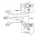
<システムの構成例>
図1に本発明の概念図を示している。管理サーバ(情報処理装置)10は、各ストレージ20(記憶装置、ディスクアレイ装置、及び、RAID装置)に記録されたアクセスに関する情報を読み出し、ホスト30からデータへのアクセスに関する情報を収集する。そして、管理サーバ10は、アクセスの効率が最高になるように最適化されたデータの保管場所(ストレージα)を検出し、データを元の場所(ストレージβ)から最適な領域(ストレージα)に移動(migration)する。
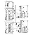
【0013】
本実施の形態について、全体構成を図2に示している。複数のホスト30は、FC(Fabric Channel)スイッチを用いたSAN(Storage Area Network)40を介して複数のストレージ20に接続する。各ホスト30には、ユーザによってアプリケーション31がインストールされる。そして各ホスト30は、このアプリケーション31の動作に必要なデータを格納する外部記憶装置として複数のストレージ20を共用する。あるいは、アプリケーション31そのものがストレージ20にインストールされる場合もある。すなわち、アプリケーション31のインストール先の相違によって、本発明の技術的範囲が狭くなることはない。また、本実施の形態でSAN40としたネットワークは、LANや専用線等の他の形態にすることができる。例えば、IPルータ等を用いたiSCSIのネットワークにできる。管理サーバ10(情報処理装置)は、SANとは異なるLAN(Local Area Network)やインターネット等の管理用のネットワーク50を介して、複数のホスト30及び複数のストレージ20と接続できる。あるいは、管理サーバ10は、SAN40に直接接続される場合もある。
【0014】
ホスト30にはアプリケーション31の他に、管理クライアント32がインストールされている。システム管理者の管理サーバ10に対する操作入力によってデータ最適化の要求等がなされると、管理クライアント32が起動する。
【0015】
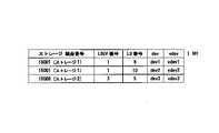
また、ホスト30ではアプリケーション31が使用する記憶領域(以下、仮想デバイス(vdev))とデバイス(dev)との対応関係を記憶している。ここでデバイスとは、ストレージ20の論理デバイス(LDEV)21とその論理デバイス21へアクセスするパス(path)との組み合わせによって定まる。例えば図2に例示した構成において、dev1は、FCスイッチ1のpath1を経由してストレージ1のLDEV1にアクセスするようになっている。また、dev2は、FCスイッチ1のpath2を経由してストレージ1のLDEV1にアクセスするようになっている。同様に、dev3は、FCスイッチ2のpath3を経由してストレージ2のLDEV3にアクセスするようになっている。図3にホスト30が記憶している仮想デバイス(vdev)とデバイス(dev)との対応関係を例示している。この図では、仮想デバイスとデバイスの対応関係とともに、デバイスに相当するストレージ20、論理デバイス(LDEV)21、論理ユニット(LU)が示されている。図3の例ではvdev1とdev1が対応している。これは、ホストのアプリケーションがvdev1に対してI/Oを発行すると、FCスイッチ1のpath1を経由してストレージ1のLDEV1に送信されることを示している。
【0016】
なお、各論理デバイス(LDEV)21は複数の論理ユニット(LU)から構成されており、各論理デバイスにアクセスするパスによって、アクセスする論理ユニットが定まる。図3の例ではdev1はLDEV1のLU8に、dev2はLDEV1のLU10に、さらにdev3はLDEV3のLU5にアクセスすることを示している。
【0017】
また、本実施例において、path1はFCスイッチ1を経由してストレージ1のFCポート1へアクセスするパスであり、帯域保証のない低速回線(1Gbps)である。また、path2はFCスイッチ1を経由してストレージ1のFCポート2へアクセスするパスであり、帯域保証のある低速回線(1Gbps)である。さらにpath3はFCスイッチ2を経由してストレージ2のFCポート3へアクセスするパスであり、帯域保証のある高速回線(2Gbps)である。
【0018】
ストレージ20には、ディスクコントローラ(制御部)22が内蔵されている。また、管理エージェント23及びコピープログラム221がインストールされている。ディスクコントローラ22に実装されたプロセッサ(CPU)上で動作するマイクロプログラムにより、ストレージ20が制御される。この動作中のマイクロプログラムによって、ホスト30からのI/Oを検知することができる。すなわち、どのホスト30からどの論理ボリューム(論理ユニット)にアクセスされたかといったアクセスの経路の情報やその頻度の情報(アクセスに関する情報)を取得することができる。管理エージェント23は、これらのアクセスに関する情報を統計情報として記録し管理している。また、ディスクコントローラ22からコピープログラム221に対して、ホスト30内のデータ(コピー元)と目的のデバイス(コピー先)が通知されると、当該コピー元のデータをコピー先に移動する処理が実施される。
【0019】
管理サーバ10は、管理プログラム101(プログラム)を有するコンピュータシステムで構成される。この管理サーバ10の機能を示すブロック図を図4に例示する。管理サーバ10は、ユーザ管理レイヤ11、オブジェクト管理レイヤ12、エージェント管理レイヤ13、及び、インタフェースレイヤ14を有する。オブジェクト管理レイヤ12は各ストレージ20に関する構成情報を蓄積するデータベースを備える。インタフェースレイヤ14はサブシステムインタフェース141及びホストインタフェース142を備える。
【0020】
管理サーバ10には、ユーザ管理レイヤ11を通じ、複数のユーザの端末A〜Cが接続される。また、管理サーバ10には、サブインタフェース141を通じ複数のストレージ20が接続される。さらに、管理サーバ10には、ホストインタフェース142を通じ、ホスト30が接続される。
【0021】
ユーザ管理レイヤ11は、ユーザの端末A〜Cを管理する。ここで、ユーザにはシステム管理者が含まれる。オブジェクト管理レイヤ12は、各ホスト30や各ストレージ20の構成、性能及び障害等の異常、並びに、その他のイベントに関する情報を取得し、データベースに格納する。このデータベースに格納する情報として、より具体的には、各ホスト30や各ストレージ20のIPアドレスやポートアドレス、各ストレージ20の内部アクセスパス、論理ボリューム、各論理ボリュームの容量やアクセス権限、及び、データ移動に関する設定、各ストレージ20間のデータコピーに関する設定、各ストレージ20の性能・制御の設定、各ストレージ20の性能データの取得、及び、保守方法の設定及び障害などの異常やユーザオペレーションによるイベントの構成情報に関するものである。その他に、FCスイッチやIPルータに関する情報など、システムの構成に関する情報も格納されている。
【0022】
このように構成されたシステムにおいて、管理サーバ10の管理プログラム101は、以下に説明するように、各ストレージ20が記録しているホスト30からのアクセスに関する情報(統計情報)に基づいて、アプリケーション31の使用するデータの格納領域を最適化する処理を行う。
【0023】
<アクセスに関する情報の記録>
まず、ストレージ20で記録しているホスト30からの統計情報について説明する。ホスト30のアプリケーション31が仮想デバイス(vdev)に対してI/Oを発行すると、ホスト30では前述した仮想デバイス(vdev)とデバイス(dev)との対応関係を参照して、対応するデバイス(dev)にアクセスする。すなわち、図2及び図3の例では、ホスト1のvdev1に対して発行されたI/Oは、ホスト1のポート(FCポートX)及びFCスイッチ1のpath1を経由してストレージ1のLDEV1のLU8に送信される。また、ホスト1のvdev2に対して発行されたI/Oは、ホスト1のポート(FCポートX)及びFCスイッチ1のpath2を経由してストレージ1のLDEV1のLU10に送信される。同様に、ホスト2のvdev2に対して発行されたI/Oは、ホスト2のポート(FCポートY)及びFCスイッチ1のpath2を経由してストレージ1のLDEV1のLU10に送信される。また、ホスト2のvdev3に対して発行されたI/Oは、ホスト2のポート(FCポートY)及びFCスイッチ2のpath3を経由してストレージ2のLDEV3のLU5に送信される。このようなホスト30のポートアドレス(WWNで定義される)やストレージ20のポートアドレス、論理ボリューム21のID(番号)などにより、アクセスの経路を特定することができる。
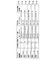
【0024】
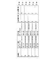
I/Oを受け取ったストレージ20では、上記のようなアクセスの経路やそのアクセスの頻度の情報をディスクコントローラ22によって検知し、管理エージェント23によって、アクセスの経路(アクセス経路)ごとに統計情報として記録している。図5に、ストレージ1に記録されている統計情報を例示する。この図は統計情報を表形式にまとめたものであり、1行ごとに1つのアクセス経路に関する情報を示している。この図に示す例では、ホスト30のポートアドレスごとにアクセスの頻度を記録している。iSCSIの場合には、ホストのIPアドレスごとに記録することもできる。例えばタイトル行500を除いた第1行目501は、ホスト1からFCスイッチ1のpath1を介してストレージ1のLDEV1のLU8にアクセスしたケースであり、ストレージ1の製品番号、LDEV番号(1)、LU番号(8)、FCスイッチ1のpath1のポートアドレス、ホスト1のポート(FCポートX)のポートアドレス、及び、この経路でアクセスされた頻度(1週間あたりの回数)の各々の値を示している。
【0025】
管理サーバ10では、週1回程度の間隔で定期的に各ストレージ20に対して問い合わせを行い、上記のようにして各ストレージ20が記録している統計情報を集約している。まず、管理サーバ10の管理プログラム101が各ストレージ20の管理エージェント23に対してLAN(管理用ネットワーク)50経由で集約の要求を送信する。これを受け取った各ストレージ20の管理エージェント23によって、各ストレージ20が記録している統計情報が管理サーバ10に返送される。管理サーバ10では、各ストレージ20から返送された統計情報を一つに集約して管理する。このようにして集約した統計情報を図6に例示している。この図では、各ストレージ20が記録している図5に例示したような統計情報と同様に、各行が1つのアクセス経路に関する情報を示している。ストレージ20の製品番号が複数であることが図5と異なる点である。
【0026】
なお、ホスト30がデータにアクセスする際に管理サーバ10を経由するように構成しておいて、管理サーバ10において上述のような統計情報を記録するようにしてもよい。あるいは、各ストレージ20が記録している統計情報が、LAN(管理用ネットワーク)50を通じて管理サーバ10の管理プログラム101に通知されるようにしてもよい。
【0027】
なお、上記のように受動的に統計情報を集計するだけでなく、「traceroute」コマンドによって、ホップ数やノードのIPアドレス等のネットワークの経路情報や応答時間を収集することもできる。
【0028】
<ベンチマークテスト>
次に、各ホスト30からストレージ20へのアクセスに関する性能の評価(ベンチマークテスト)について説明する。管理サーバ10は、一日に一回程度の頻度で定期的に、各ホスト30から各ストレージ20へのアクセスに際してデータの読み取り(read)や書きこみ(write)に要する時間を計測している。その計測結果のデータを元にして、当該ホスト30から当該ストレージ20へのアクセスに関する性能(アクセス性能)を評価している。管理サーバ10の管理プログラム101は、各ホスト30の管理クライアント32に対して、LAN(管理用ネットワーク)50を介して適宜な順番で、ストレージ20の論理ユニットを指定する情報(ストレージ20へアクセスするパスのポートアドレスと論理ユニット番号)を含めてベンチマークテストの実施の要求を送信する。この要求を受け取ったホスト30の管理クライアント32では、指定された論理ユニットに対して、所定のサイズのデータの読み取り及び書き込みに要する時間を計測する。そして、その結果を管理サーバ10に返送する。これを受け取った管理サーバ10の管理プログラム101はその結果を記録する。計測の結果として記録される内容は、アクセス元であるホスト30のポートアドレス、アクセス先であるストレージ20のポートアドレスと論理ユニット番号、読み取り時間と書きこみ時間などである。管理サーバ10は、このようなベンチマークテストの要求を各ホスト30の管理クライアント32から各ストレージ20の論理ユニットに対して順次行い、その結果を集約し管理している。集約した計測結果を図7に例示している。図7では、一回の計測についての結果を1行に示している。例えば図7のタイトル行700を除いた1行目701には、ホスト1のポート(FCポートX)からストレージ1のLDEV1のLU8にアクセスした際に、所定のサイズのデータを読み取る時間が6秒、同じサイズのデータを書きこむ時間が11秒であったことを示している。また、3行目703の計測結果は、ホスト2のポート(FCポートY)からストレージ1のLDEV1のLU10にアクセスした際に、所定のサイズのデータを読み取る時間が5秒、同じサイズのデータを書きこむ時間が9秒であったことを示している。同様に、5行目705の計測結果は、ホスト2のポート(FCポートY)からストレージ2のLDEV3のLU5にアクセスした際に、所定のサイズのデータを読み取る時間が2秒、同じサイズのデータを書きこむ時間が4秒であったことを示している。
【0029】
<最適な格納領域の判定>
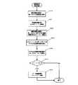
管理サーバ10では、例えば各ストレージ20が記録している統計情報を管理サーバ10で集約した際に、あるいは管理者の操作入力時などに、ストレージ20のアプリケーションが使用するデータの格納領域を最適化する処理を行う。その具体的手順について、図8の処理フロー図を用いて説明する。まず、管理サーバ10の管理プログラム101は、図6に例示した統計情報を参照し、各ストレージ20の論理デバイス(LDEV)21毎に、以下に説明する評価方法に従って評価値を算出する(図8のステップ810)。各論理デバイス21の評価値とは、ストレージ20の当該論理デバイス21への各アクセス経路についての統計情報において、各経路へのアクセス数(アクセス頻度)について全アクセス経路へのアクセス総数に対する割合と、当該アクセス経路へのアクセス数とを乗じたもののうちで、最大となるものである。すなわち、当該論理デバイス21への各アクセス経路についての統計情報のうちもっともアクセス数(アクセス頻度)の多いアクセス経路において、全アクセス経路へのアクセス総数に対する当該経路へのアクセス数の割合と、当該アクセス経路へのアクセス数とを乗じたものである。例えば図6に示した統計情報において、LDEV1に対する評価値は、次のようにして求める。まず、LDEV1へのアクセスのうち、最もアクセス数が多いアクセス経路は、第3行目603に示されたホスト2のポート(FCポートY)からFCスイッチ1のpath2を経由してストレージ1のLU10へアクセスするものであり、そのアクセス回数(アクセス頻度)は週に3000回である。そしてこの数は、LDEV1へのアクセスの総数、すなわち1行目601に示されたホスト1のポート(FCポートX)からFCスイッチ1のpath1経由によるストレージ1のLU8へのアクセスの回数(週に1000回)と2行目602に示されたホスト1のポート(FCポートX)からFCスイッチ1のpath2経由によるストレージ1のLU10へのアクセスの回数(週に500回)と当該アクセス経路(3行目603のアクセス経路)でのアクセス回数(週に3000回)とを合計したアクセス総数(週に4500回)に対して、3分の2の割合である。従ってLDEV1の評価値は、3000に3分の2を乗じた数値、すなわち2010となる。同様に、LDEV3に対する評価値は、図6の4行目604に示されたホスト1のポート(FCポートX)からFCスイッチ2のpath3経由によるストレージ2のLU5へのアクセスの回数(週に10回)と、5行目605に示されたホスト2のポート(FCポートY)からFCスイッチ2のpath3経由によるストレージ2のLU5へのアクセスの回数(週に90回)とに基づいて、90に100分の90を乗じた数値、すなわち90と算出される。このようにして算出された各論理デバイス21への評価値のうち最大値となった各論理デバイス21を検出する(ステップ820)。図6の例では、LDEV1がこれに該当する。
【0030】
また、管理サーバ10の管理プログラム101は、統計情報を参照した際に、各論理デバイス21に対して最もアクセス回数の多い(アクセス頻度の高い)ホスト30を検出する(ステップ830)。すなわち、各論理デバイス21へのアクセス経路の統計情報を参照してホスト30のポートアドレス毎にアクセス回数を集計し、アクセス総数が最も多いホスト30を特定(検出)する。図6の例において、LDEV1に対するホスト1のポート(FCポートX)からのアクセスは、1行目601に示されているpath1経由の1000回と、2行目602に示されているpath2経由の500回であるから、アクセス総数は1500回と集計される。またホスト2のポート(FCポートY)からのアクセス総数は3行目603に示されている3000回と集計される。したがって、LDEV1へのアクセス回数が最も多いのはホスト2と特定される。同様に、LDEV3へのホスト1からのアクセス回数は4行目604に示されている10回、ホスト2からのアクセス回数は5行目605に示されている90回であるので、LDEV3へのアクセス回数が最も多いのはホスト2と特定される。ここで特定したホスト30がアクセスするデータを、後述する手順に従ってよりアクセス性能の高い記憶領域に移動することになる。
【0031】
次に管理プログラム101は、前述したベンチマークテストの結果に基づき、各論理デバイス21に対して、前述の手順により特定したアクセス回数が最多のホスト30からのアクセスに関する性能の評価値(以下、アクセス性能評価値と称する)を算出する(ステップ840)。その算出方法について説明する。まず、管理者の管理サーバ10への操作入力等によって、当該論理デバイス21に対する読み取り(read)と書き込み(write)の優先の度合いを決定する。具体的には、読み取りの係数をa、書き込みの係数をbとして、a+b=1となるようにa、bを決定する。
【0032】
その次に、図7に例示したベンチマークテストの結果を参照し、各論理デバイス21へのアクセス経路について、アクセス回数が最多であるホスト30からのアクセスにおける読み取り時間と書き込み時間のデータを取り出して、各々の数値に先の係数a、bをそれぞれ乗じたものを合計する。この値を各論理デバイス21内の論理ユニットに対する当該ホスト30からのアクセス性能評価値とする。当該ホストから当該論理デバイスに対し複数アクセス経路がある場合には、このように算出した値のうちの最小のものを当該ホストから当該論理デバイスへのアクセス性能評価値とする。このアクセス性能評価値の算出方法について、図6および図7に示す例を用いて説明する。読み取りの係数aを0.5、書き取りの係数bを0.5とする(つまり、読み取りと書き取りを同程度に優先する)と、ホスト2からLDEV1のLU10へのアクセス性能評価値は、読み取り時間5秒に係数aを乗じたものと、書き取り時間9秒に係数bを乗じたものとの合計、すなわち5×0.5+9×0.5=7として算出される。同様にしてホスト2からLDEV3のLU5へのアクセス性能評価値は読み取り時間2秒に係数aを乗じたものと、書き取り時間4秒に係数bを乗じたものとの合計、すなわち2×0.5+4×0.5=3として算出される。次に、このようにして算出されたアクセス性能評価値が最小になる記憶領域(論理デバイス21の論理ユニット)を検出する(ステップ850)。ここで検出された記憶領域が、当該ホスト30からのアクセス性能が高い記憶領域であることを意味している。この例では、LDEV3のLU5がホスト2にとってアクセス性能が高い記憶領域であると検出されたことになる。そして、ここで検出された記憶領域に、先に特定したホスト30がアクセスするデータを、後述の手順に従って移動する(ステップ870)ことになる。したがってこの図の例では、ホスト2のアプリケーション12が使用するデータを、LDEV1からLDEV3へ移動することと結論づけられる。
【0033】
なお、移動候補となっていたホスト30のデータが、アクセス性能評価値が最小となった記憶領域に記録されている場合(ステップ860)には、移動する必要はない。また、移動候補となっていたホスト30のデータの記憶領域と、アクセス性能評価値が最小となった記憶領域とが同じ論理デバイス21である場合には、アクセスするパスを定義し直すことができる。
【0034】
また、本実施の形態では、ベンチマークテストの結果をもとにアクセス性能の高い記憶領域を検出して移動先としたが、ホスト30からのアクセス経路が最短になるストレージ20や空き容量が最大あるストレージ20の記憶領域をアクセス効率の高い記憶領域とし、移動先に指定するようにできる。
【0035】
さらに、相対的にアクセス頻度の高いホスト30のデータを移動元としたが、ホスト30からのアクセス経路が最長のストレージ20や空き容量が最小のストレージ20の記憶領域や、ベンチマークテストの結果をもとにアクセス性能の低い記憶領域のデータを移動元として特定するようにできる。
【0036】
<データの移動処理>
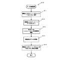
前述のようにして移動するデータが指定されると、以下に説明する手順に従ってデータを移動する。図9に、このデータ移動処理の処理フロー図を示している。まず、管理サーバ10の管理プログラム101は、各ホスト30の管理クライアント32にデータ移動の旨を通知する。通知を受けた各管理クライアント32では、移動元のデータが格納されている論理デバイスに対応するデバイス(dev)に対して「読み取り専用(read only)」を設定する(ステップ871)。例えば、前述の図6および図7に示した例において、LDEV1からLDEV3にデータを移動する場合には、LDEV1に対応するdev1およびdev2に対して「読み取り専用(read only)」を設定する。
【0037】
また、管理サーバ10の管理プログラム101は、データ移動元であるストレージ20の管理エージェント23に対して移動対象のデータが格納されている論理デバイス21、及び、移動先として指定する論理デバイス21を通知する。通知を受けた管理エージェント23がディスクコントローラ22のコピープログラム221にその旨を通知すると、コピープログラム221は、移動元の論理デバイス21に格納されているデータを、SAN40を介して、移動先である論理デバイス21にコピー(移動)する処理を実施する(ステップ872)。例えば図6及び図7の例においては、LDEV1のデータを、LDEV3へコピーする処理が行われる。このときに、合わせてLDEV3(dev3に対応)データをLDEV1にコピーする処理を行っておいて、データの入れ替えを実現するようにしてもよい。
【0038】
そして、各ホスト30の管理クライアント32は、記憶している仮想デバイス(vdev)とデバイス(dev)との対応関係を、データ移動に対応するように更新する(ステップ873)。例えば上記の図6及び図7に示した例では、ホスト2で記憶している対応関係について、vdev1にdev3を、またvdev2にdev3を対応させるように更新する。移動元と移動先とのデータを入れ替えるためにLDEV3のデータをLDEV1に移動した場合には、vdev3をdev1およびdev2に対応させるように更新する。この場合は、vdev3に対するI/Oがdev1とdev2に対応する2つのパスに均等に振り分けられることになる
さらに、移動元のデータを削除する(ステップ874)。それとともに、ステップ871にて「読み取り専用(read only)」に設定した仮想デバイス(vdev)に対応するデバイス(dev)の設定を解除して(ステップ875)、データ移動処理を終了させる。
なお、移動元のデータを削除せずにデータ移動処理を終了させることもできる。
【0039】
その後、管理サーバ10の管理プログラム101の指示により、図5に例示したような各ストレージ20が管理する統計情報、及び、図7に例示したような管理サーバ10が管理する各ホスト30から各ストレージ20へのベンチマークテストの結果を初期化する。そして、これ以降のアクセスに関する情報の記録に基づいて、またデータ格納領域の最適化の処理(ステップ810〜875)が繰り返されることになる。
【0040】
<その他>
なお、図2では、管理サーバ10は一つのみが示されているが、複数存在してもよい。また、管理サーバ10はストレージ20の内部に設置されてもよい。さらに、管理サーバ10の機能を有する管理サーバ部がストレージ20に組み込まれた構成としてもよい。すなわち、「管理サーバ」という用語には「管理サーバ部」としての意味も含む。また、ストレージ20から物理的に離れた場所に位置してもよい。
【0041】
以上、本発明について、その実施の形態に基づき具体的に説明したが、これに限定されるものではなく、その要旨を逸脱しない範囲で種々変更可能である。
【0042】
本実施の形態によれば次の効果を奏することができる。
管理サーバは、各ホストからのアクセスに関する情報に基づいて、各ホストの使用するデータをアクセスの効率の高い記憶領域へ移動させる。このことにより、システム全体のアクセス効率が向上する。
【0043】
管理サーバは、アクセス頻度に基づいてアクセスの効率を判定する。このことにより、システム全体のアクセス頻度が平均化し、システムを全体的にみて記憶装置やホストの負荷を分散させることができる。
【0044】
管理サーバは、アクセスに要する時間に基づいてアクセスの効率を判定する。このことにより、システム全体としてアクセス時間が平均化し、システムを全体的にみて、記憶装置ホストの負荷を分散させることができる。
【0045】
管理サーバは、記憶装置の空き容量に基づいてアクセスの効率を判定する。このことにより、システムを全体的にみて記憶装置の記憶領域を有効に利用することができる。
【0046】
管理サーバは、アクセスの経路の長さに基づいてアクセスの効率を判定する。このことにより、アクセスの経路の長さを平均化することで、システム全体としてアクセスの効率を向上することができる。
【0047】
管理サーバは、ホストから記憶領域へのアクセスに関する性能を計測し、その計測の結果に基づいてアクセスの効率を判定する。このことにより、時々刻々と変化する状況に柔軟に対応してシステム全体のアクセスの効率を向上させることができる。
【0048】
【発明の効果】
各ホストの使用するデータをアクセスの効率の高い記憶領域へ移動させることが可能となる。
【図面の簡単な説明】
【図1】本発明の概念を示す図である。
【図2】本発明の一実施の形態に係るシステム構成例を示すブロック図である。
【図3】本発明の一実施の形態に係る仮想デバイスとデバイスとの対応関係を例示する図である。
【図4】本発明の一実施の形態に係る管理サーバの機能を示すブロック図である。
【図5】本発明の一実施の形態に係るストレージが記録する統計情報を例示する図である。
【図6】本発明の一実施の形態に係る管理サーバが集約する統計情報を例示する図である。
【図7】本発明の一実施の形態に係るベンチマークテストの結果を例示する図である。
【図8】本発明の一実施の形態に係る最適領域判定処理の処理フロー図である。
【図9】本発明の一実施の形態に係るデータ移動処理の処理フロー図である。
【符号の説明】
10 管理サーバ
20 ストレージ
22 ディスクコントローラ
23 管理エージェント
30 ホスト
31 アプリケーション
32 管理クライアント
40 SAN
50 LAN(管理用ネットワーク)
101 管理プログラム
221 コピープログラム[0001]
TECHNICAL FIELD OF THE INVENTION
The present invention relates to a program, an information processing method, an information processing device, and a storage device.
[0002]
[Prior art]
When the host operates the application, a plurality of storages (disk array devices, RAID (Redundant Array for Inexpensive Disks) devices) are used as storage devices. The storage is composed of a plurality of disks. Specifically, the host is connected to a storage via a network such as a SAN (Storage Area Network) and distributes and stores data in logical volumes on a plurality of disk devices.
[0003]
With regard to such data distribution, in the method of deciding in which storage the data of a certain host is stored based only on its logical classification, frequently accessed data may be stored in a storage that takes a long time to access. There is also. Therefore, in order to construct an efficient system, a technique for determining a storage area (storage area) for storing data based on information such as the time required for actual access and the access frequency is required.
[0004]
As a technique for allocating storage areas from such a viewpoint, Japanese Patent Application Laid-Open No. 2001-350707 discloses a technique of allocating storages (storage devices) and storage areas (logical volumes) based on collected evaluation values. According to this conventional technique, a storage (storage area) and a storage area are determined based on evaluation values collected by a host (computer) for access speed and the like for each application (program) in accordance with matters that the user places importance on access frequency, backup frequency, reliability and the like. Is assigned.
According to this conventional technique, storage and storage areas can be finely allocated according to the allocation policy of the user, so that an efficient system can be constructed.
[0005]
[Problems to be solved by the invention]
In the above-described conventional technology, a storage or a logical unit (logical volume) to be accessed by a host when executing an application is determined based on evaluation data collected by the host itself.
However, the storage and storage area that can be allocated are only devices within the range that can be used and evaluated by the host itself, and cannot be allocated to storage and storage areas not used by the host. Was not enough.
[0006]
Therefore, a management server (information processing device) that grasps the overall configuration of a system including a plurality of hosts and a plurality of storages connected to the same network, and determines whether the storage that is close to the host or the access speed from the host is low. If a storage area with high access efficiency, such as a fast storage area, can be allocated, a more efficient system can be constructed.
[0007]
The present invention has been made in view of the above background, and provides a program, an information processing method, an information processing device, and a storage device.
[0008]
[Means to solve the problem]
The technology according to the present invention for achieving the above object manages a plurality of storage devices connected by a host via a network, and refers to information on access from the hosts to the storage devices. Detecting a storage area with low access efficiency in the storage device based on the information regarding the access, and detecting a host with low access efficiency with respect to the storage area with low access efficiency based on the information regarding the access. Detecting, at least, a storage area with high access efficiency by the host with low access efficiency, and storing the data stored in the storage area with low access efficiency and used by the host with low access efficiency, It is assumed that the process of moving to a storage area with high efficiency is executed.
[0009]
In addition, the problems disclosed by the present application and the solution thereof will be clarified by the description of the embodiments of the invention and the drawings.
[0010]
BEST MODE FOR CARRYING OUT THE INVENTION
At least the following will be made clear by the description in this specification.
The information on the access includes at least an access frequency, and the access efficiency can be determined based on the access frequency.
The information on the access includes at least a time required for the access, and the efficiency of the access can be determined based on the time required for the access.
The information on the access includes at least a free space of the storage device, and the efficiency of the access can be determined based on the free space of the storage device.
The information on the access includes at least information on an access route, and the access efficiency can be determined based on the length of the access route.
[0011]
Performance of access from the host to the storage area in the storage device is measured, and the efficiency of access from the host can be determined based on the measurement result.
[0012]
<Example of system configuration>
FIG. 1 shows a conceptual diagram of the present invention. The management server (information processing device) 10 reads information related to access recorded in each storage 20 (storage device, disk array device, and RAID device), and collects information related to data access from the
[0013]
FIG. 2 shows the overall configuration of the present embodiment. The plurality of
[0014]
A
[0015]
The
[0016]
Each logical device (LDEV) 21 is composed of a plurality of logical units (LUs), and the logical unit to access is determined by the path for accessing each logical device. In the example of FIG. 3, dev1 accesses the LU8 of the LDEV1, dev2 accesses the LU10 of the LDEV1, and dev3 accesses the LU5 of the LDEV3.
[0017]
In the present embodiment, path1 is a path for accessing the
[0018]
The
[0019]
The
[0020]
Terminals A to C of a plurality of users are connected to the
[0021]
The
[0022]
In the system configured as described above, the
[0023]
<Record of access information>
First, the statistical information from the
[0024]
In the
[0025]
The
[0026]
The
[0027]
As described above, in addition to passively collecting statistical information, network route information such as the number of hops and the IP address of a node, and response time can be collected by a “traceroute” command.
[0028]
<Benchmark test>
Next, evaluation of performance (benchmark test) related to access from each
[0029]
<Determination of optimal storage area>
The
[0030]
Further, when the
[0031]
Next, the
[0032]
Next, referring to the results of the benchmark test illustrated in FIG. 7, for the access path to each
[0033]
If the data of the
[0034]
Further, in the present embodiment, a storage area with high access performance is detected and set as a destination based on the result of the benchmark test. However, the
[0035]
Furthermore, although the data of the
[0036]
<Data transfer processing>
When the data to be moved is specified as described above, the data is moved according to the procedure described below. FIG. 9 shows a processing flow diagram of this data movement processing. First, the
[0037]
The
[0038]
Then, the
Further, the source data is deleted (step 874). At the same time, the setting of the device (dev) corresponding to the virtual device (vdev) set to “read only” in step 871 is canceled (step 875), and the data migration processing ends.
Note that the data transfer process can be terminated without deleting the transfer source data.
[0039]
Thereafter, in accordance with an instruction of the
[0040]
<Others>
Although only one
[0041]
As described above, the present invention has been specifically described based on the embodiments. However, the present invention is not limited thereto, and various changes can be made without departing from the gist of the present invention.
[0042]
According to the present embodiment, the following effects can be obtained.
The management server moves data used by each host to a storage area with high access efficiency based on information on access from each host. This improves the access efficiency of the entire system.
[0043]
The management server determines access efficiency based on the access frequency. As a result, the access frequency of the entire system is averaged, and the loads on the storage devices and the hosts can be distributed over the entire system.
[0044]
The management server determines the efficiency of the access based on the time required for the access. As a result, the access time is averaged for the entire system, and the load on the storage device host can be dispersed in the entire system.
[0045]
The management server determines the access efficiency based on the free space of the storage device. This makes it possible to effectively use the storage area of the storage device as a whole system.
[0046]
The management server determines access efficiency based on the length of the access path. Thus, by averaging the length of the access path, it is possible to improve the access efficiency of the entire system.
[0047]
The management server measures the performance related to access from the host to the storage area, and determines the access efficiency based on the measurement result. As a result, the efficiency of access to the entire system can be improved by flexibly responding to situations that change every moment.
[0048]
【The invention's effect】
Data used by each host can be moved to a storage area with high access efficiency.
[Brief description of the drawings]
FIG. 1 is a diagram showing the concept of the present invention.
FIG. 2 is a block diagram illustrating a system configuration example according to an embodiment of the present invention.
FIG. 3 is a diagram exemplifying a correspondence between a virtual device and a device according to an embodiment of the present invention;
FIG. 4 is a block diagram showing functions of a management server according to one embodiment of the present invention.
FIG. 5 is a diagram illustrating an example of statistical information recorded by a storage according to an embodiment of the present invention.
FIG. 6 is a diagram illustrating an example of statistical information collected by a management server according to an embodiment of the present invention;
FIG. 7 is a diagram illustrating a result of a benchmark test according to an embodiment of the present invention.
FIG. 8 is a processing flowchart of an optimum area determination process according to one embodiment of the present invention.
FIG. 9 is a processing flowchart of data movement processing according to the embodiment of the present invention.
[Explanation of symbols]
10 Management server
20 Storage
22 Disk Controller
23 Management Agent
30 hosts
31 Application
32 Management Client
40 SAN
50 LAN (management network)
101 Management program
221 Copy Program
Claims (23)
Translated fromJapanese前記各ホストから前記各記憶装置へのアクセスに関する情報を参照するステップと、
前記アクセスに関する情報に基づき、前記記憶装置におけるアクセスの効率の低い記憶領域を検出するステップと、
前記アクセスに関する情報に基づき、前記アクセスの効率の低い記憶領域に対してアクセスの効率の低いホストを検出するステップと、
少なくとも前記アクセスの効率の低いホストによるアクセスの効率の高い記憶領域を検出するステップと、
前記アクセスの効率の低い記憶領域に格納され、かつ、前記アクセスの効率の低いホストが使用するデータを、前記アクセスの効率の高い記憶領域に移動させるステップと、
を実行させるためのプログラム。An information processing device that manages a plurality of storage devices connected by a host via a network includes:
Referencing information on access from the respective hosts to the respective storage devices;
Detecting a storage area with low access efficiency in the storage device based on the access information;
Based on the information on the access, detecting a host with low access efficiency to the storage area with low access efficiency,
Detecting at least a storage area with high access efficiency by the host with low access efficiency;
Moving the data stored in the storage area with low access efficiency and used by the host with low access efficiency to the storage area with high access efficiency,
The program to execute.
前記各ホストから前記各記憶装置へのアクセスに関する情報を参照するステップと、
前記アクセスに関する情報に基づき、前記記憶装置におけるアクセスの効率の低い記憶領域を検出するステップと、
前記アクセスに関する情報に基づき、前記アクセスの効率の低い記憶領域に対してアクセスの効率の低いホストを検出するステップと、
少なくとも前記アクセスの効率の低いホストによるアクセスの効率の高い記憶領域を検出するステップと、
前記アクセスの効率の低い記憶領域に格納され、かつ、前記アクセスの効率の低いホストが使用するデータを、前記アクセスの効率の高い記憶領域に移動させるステップと、
を備えることを特徴とする情報処理方法。An information processing method by an information processing apparatus that manages a plurality of storage devices connected by a host via a network,
Referencing information on access from the respective hosts to the respective storage devices;
Detecting a storage area with low access efficiency in the storage device based on the access information;
Based on the information on the access, detecting a host with low access efficiency to the storage area with low access efficiency,
Detecting at least a storage area with high access efficiency by the host with low access efficiency;
Moving the data stored in the storage area with low access efficiency and used by the host with low access efficiency to the storage area with high access efficiency,
An information processing method comprising:
前記各ホストから前記各記憶装置へのアクセスに関する情報を参照するステップと、
前記アクセスに関する情報に基づき、アクセスの効率の低い前記記憶装置の記憶領域を検出するステップと、
前記アクセスに関する情報に基づき、前記アクセスの効率の低い記憶領域に対してアクセスの効率の低いホストを検出するステップと、
少なくとも前記アクセスの効率の低いホストによるアクセスの効率の高い記憶領域を検出するステップと、
前記アクセスの効率の低い記憶領域に格納され、かつ、前記アクセスの効率の低いホストが使用するデータを、前記アクセスの効率の高い記憶領域に移動させるステップと、
を備えることを特徴とする情報処理方法。An information processing method by at least one control unit among a plurality of storage devices to which a plurality of hosts are connected via a network,
Referencing information on access from the respective hosts to the respective storage devices;
Detecting a storage area of the storage device with low access efficiency based on the information on the access;
Based on the information on the access, detecting a host with low access efficiency to the storage area with low access efficiency,
Detecting at least a storage area with high access efficiency by the host with low access efficiency;
Moving the data stored in the storage area with low access efficiency and used by the host with low access efficiency to the storage area with high access efficiency,
An information processing method comprising:
前記各ホストから前記各記憶装置へのアクセスに関する情報を参照する手段と、
前記アクセスに関する情報に基づき、前記記憶装置におけるアクセスの効率の低い記憶領域を検出する手段と、
前記アクセスに関する情報に基づき、前記アクセスの効率の低い記憶領域に対してアクセスの効率の低いホストを検出する手段と、
少なくとも前記アクセスの効率の低いホストによるアクセスの効率の高い記憶領域を検出する手段と、
前記アクセスの効率の低い記憶領域に格納され、かつ、前記アクセスの効率の低いホストが使用するデータを、前記アクセスの効率の高い記憶領域に移動させる手段と、
を備えることを特徴とする情報処理装置。An information processing apparatus in which a host manages a plurality of storage devices connected via a network,
Means for referring to information regarding access from the respective hosts to the respective storage devices,
Means for detecting a storage area with low access efficiency in the storage device, based on the information regarding the access,
Means for detecting a host with low access efficiency for the storage area with low access efficiency, based on the information on the access,
Means for detecting a storage area with high access efficiency by at least the host with low access efficiency;
Means stored in the storage area with low access efficiency, and data used by the host with low access efficiency, moved to a storage area with high access efficiency,
An information processing apparatus comprising:
前記各ホストからのアクセスに関する情報を記録する手段と、
前記アクセスに関する情報を前記情報処理装置に参照させる手段と、
指定されたデータを指定された記憶領域へ移動する手段と、
を備えることを特徴とする記憶装置。A storage device managed by the information processing device according to claim 16,
Means for recording information about access from each of the hosts,
Means for causing the information processing device to refer to the information regarding the access,
Means for moving specified data to a specified storage area;
A storage device comprising:
Priority Applications (3)
| Application Number | Priority Date | Filing Date | Title |
|---|---|---|---|
| JP2002174945AJP2004021557A (en) | 2002-06-14 | 2002-06-14 | Program, information processing method, information processing device, and storage device |
| US10/371,898US7143096B2 (en) | 2002-06-14 | 2003-02-20 | Information processing method and system |
| US11/586,445US20070043919A1 (en) | 2002-06-14 | 2006-10-24 | Information processing method and system |
Applications Claiming Priority (1)
| Application Number | Priority Date | Filing Date | Title |
|---|---|---|---|
| JP2002174945AJP2004021557A (en) | 2002-06-14 | 2002-06-14 | Program, information processing method, information processing device, and storage device |
Publications (1)
| Publication Number | Publication Date |
|---|---|
| JP2004021557Atrue JP2004021557A (en) | 2004-01-22 |
Family
ID=29728001
Family Applications (1)
| Application Number | Title | Priority Date | Filing Date |
|---|---|---|---|
| JP2002174945APendingJP2004021557A (en) | 2002-06-14 | 2002-06-14 | Program, information processing method, information processing device, and storage device |
Country Status (2)
| Country | Link |
|---|---|
| US (2) | US7143096B2 (en) |
| JP (1) | JP2004021557A (en) |
Cited By (10)
| Publication number | Priority date | Publication date | Assignee | Title |
|---|---|---|---|---|
| JP2005267546A (en)* | 2004-03-22 | 2005-09-29 | Hitachi Ltd | Disk control device and connection management method for network-connected storage in disk control device |
| JP2005267274A (en)* | 2004-03-18 | 2005-09-29 | Hitachi Ltd | Storage system and computer system |
| JP2005339215A (en)* | 2004-05-27 | 2005-12-08 | Hitachi Ltd | Disk array device and control method thereof |
| JP2006107019A (en)* | 2004-10-04 | 2006-04-20 | Hitachi Ltd | Disk array device |
| JP2006126993A (en)* | 2004-10-27 | 2006-05-18 | Hitachi Ltd | Method and apparatus for selecting data migration destination |
| JP2006268093A (en)* | 2005-03-22 | 2006-10-05 | Hitachi Ltd | Storage control method and system |
| JP2007058637A (en)* | 2005-08-25 | 2007-03-08 | Hitachi Ltd | Storage system, management computer and data migration method |
| JP2008108019A (en)* | 2006-10-25 | 2008-05-08 | Hitachi Ltd | Blade server system |
| JP2014026321A (en)* | 2012-07-24 | 2014-02-06 | Fujitsu Ltd | Storage device, information processing device, information processing system, access control method, and access control program |
| JP2019175415A (en)* | 2018-03-28 | 2019-10-10 | 廣達電腦股▲ふん▼有限公司Quanta Computer Inc. | Method and system for allocating system resources |
Families Citing this family (15)
| Publication number | Priority date | Publication date | Assignee | Title |
|---|---|---|---|---|
| ATE306102T1 (en) | 2001-01-03 | 2005-10-15 | Nice Systems Ltd | CONTENT BASED STORAGE MANAGEMENT |
| US7627587B2 (en)* | 2003-09-25 | 2009-12-01 | Unisys Corporation | System and method for improving information retrieval from a database |
| US20050071596A1 (en)* | 2003-09-26 | 2005-03-31 | International Business Machines Corporation | Method, apparatus and program storage device for providing automatic performance optimization of virtualized storage allocation within a network of storage elements |
| JP4713843B2 (en)* | 2004-04-15 | 2011-06-29 | 株式会社日立製作所 | Backup method |
| US8224784B2 (en)* | 2004-08-13 | 2012-07-17 | Microsoft Corporation | Combined computer disaster recovery and migration tool for effective disaster recovery as well as the backup and migration of user- and system-specific information |
| JP2006178811A (en)* | 2004-12-24 | 2006-07-06 | Hitachi Ltd | Storage system and storage system path control method |
| US20060161753A1 (en)* | 2005-01-18 | 2006-07-20 | Aschoff John G | Method, apparatus and program storage device for providing automatic performance optimization of virtualized storage allocation within a virtualized storage subsystem |
| US20060288036A1 (en)* | 2005-06-17 | 2006-12-21 | Microsoft Corporation | Device specific content indexing for optimized device operation |
| US8150816B2 (en)* | 2005-12-29 | 2012-04-03 | Nextlabs, Inc. | Techniques of optimizing policies in an information management system |
| JP4969972B2 (en)* | 2006-09-27 | 2012-07-04 | 株式会社日立製作所 | Apparatus and method for controlling the number of logical paths |
| JP5263169B2 (en)* | 2007-10-25 | 2013-08-14 | 富士通株式会社 | Information providing method, relay method, information holding device, repeater |
| JP4551947B2 (en)* | 2008-05-23 | 2010-09-29 | 株式会社日立製作所 | Device that manages the electronic devices that make up the storage system |
| US20120011329A1 (en) | 2010-07-09 | 2012-01-12 | Hitachi, Ltd. | Storage apparatus and storage management method |
| US20120096059A1 (en)* | 2010-10-13 | 2012-04-19 | Hitachi, Ltd. | Storage apparatus and file system management method |
| JP2014174845A (en)* | 2013-03-11 | 2014-09-22 | Fujitsu Ltd | Performance evaluation support program, performance evaluation support device, and performance evaluation support method |
Family Cites Families (13)
| Publication number | Priority date | Publication date | Assignee | Title |
|---|---|---|---|---|
| JPH02122361A (en) | 1988-11-01 | 1990-05-10 | Fuji Xerox Co Ltd | Data base control method for computer system |
| JPH03294938A (en) | 1990-04-12 | 1991-12-26 | Nec Corp | Distributed communication system |
| JP3444385B2 (en) | 1995-09-19 | 2003-09-08 | 日立ソフトウエアエンジニアリング株式会社 | Access frequency threshold control method for distributed database |
| US6269382B1 (en)* | 1998-08-31 | 2001-07-31 | Microsoft Corporation | Systems and methods for migration and recall of data from local and remote storage |
| US6330621B1 (en)* | 1999-01-15 | 2001-12-11 | Storage Technology Corporation | Intelligent data storage manager |
| JP2001337790A (en) | 2000-05-24 | 2001-12-07 | Hitachi Ltd | Storage system and hierarchical management control method |
| JP2001350707A (en) | 2000-06-06 | 2001-12-21 | Hitachi Ltd | Information processing system and storage device allocation method |
| US6950871B1 (en) | 2000-06-29 | 2005-09-27 | Hitachi, Ltd. | Computer system having a storage area network and method of handling data in the computer system |
| US6678752B1 (en)* | 2000-09-28 | 2004-01-13 | International Business Machines Corporation | Data storage system with automatic storage request analysis and selection of optimal output media type |
| US20020188592A1 (en) | 2001-06-11 | 2002-12-12 | Storage Technology Corporation | Outboard data storage management system and method |
| US7171396B2 (en)* | 2002-04-04 | 2007-01-30 | Hewlett-Packard Development Company, L.P. | Method and program product for specifying the different data access route for the first data set includes storing an indication of the different access for the first data set providing alternative data access routes to a data storage |
| JP2003330762A (en) | 2002-05-09 | 2003-11-21 | Hitachi Ltd | Storage system control method, storage system, switch, and program |
| JP4322031B2 (en) | 2003-03-27 | 2009-08-26 | 株式会社日立製作所 | Storage device |
- 2002
- 2002-06-14JPJP2002174945Apatent/JP2004021557A/enactivePending
- 2003
- 2003-02-20USUS10/371,898patent/US7143096B2/ennot_activeExpired - Fee Related
- 2006
- 2006-10-24USUS11/586,445patent/US20070043919A1/ennot_activeAbandoned
Cited By (12)
| Publication number | Priority date | Publication date | Assignee | Title |
|---|---|---|---|---|
| JP2005267274A (en)* | 2004-03-18 | 2005-09-29 | Hitachi Ltd | Storage system and computer system |
| JP2005267546A (en)* | 2004-03-22 | 2005-09-29 | Hitachi Ltd | Disk control device and connection management method for network-connected storage in disk control device |
| JP2005339215A (en)* | 2004-05-27 | 2005-12-08 | Hitachi Ltd | Disk array device and control method thereof |
| JP2006107019A (en)* | 2004-10-04 | 2006-04-20 | Hitachi Ltd | Disk array device |
| JP2006126993A (en)* | 2004-10-27 | 2006-05-18 | Hitachi Ltd | Method and apparatus for selecting data migration destination |
| JP2006268093A (en)* | 2005-03-22 | 2006-10-05 | Hitachi Ltd | Storage control method and system |
| JP2007058637A (en)* | 2005-08-25 | 2007-03-08 | Hitachi Ltd | Storage system, management computer and data migration method |
| JP2008108019A (en)* | 2006-10-25 | 2008-05-08 | Hitachi Ltd | Blade server system |
| JP2014026321A (en)* | 2012-07-24 | 2014-02-06 | Fujitsu Ltd | Storage device, information processing device, information processing system, access control method, and access control program |
| US9336093B2 (en) | 2012-07-24 | 2016-05-10 | Fujitsu Limited | Information processing system and access control method |
| JP2019175415A (en)* | 2018-03-28 | 2019-10-10 | 廣達電腦股▲ふん▼有限公司Quanta Computer Inc. | Method and system for allocating system resources |
| US10728172B2 (en) | 2018-03-28 | 2020-07-28 | Quanta Computer Inc. | Method and system for allocating system resources |
Also Published As
| Publication number | Publication date |
|---|---|
| US7143096B2 (en) | 2006-11-28 |
| US20030233382A1 (en) | 2003-12-18 |
| US20070043919A1 (en) | 2007-02-22 |
Similar Documents
| Publication | Publication Date | Title |
|---|---|---|
| JP2004021557A (en) | Program, information processing method, information processing device, and storage device | |
| JP4749140B2 (en) | Data migration method and system | |
| US7680847B2 (en) | Method for rebalancing free disk space among network storages virtualized into a single file system view | |
| US8166270B2 (en) | Storage control apparatus, data management system and data management method for determining storage heirarchy based on a user policy | |
| US7302541B2 (en) | System and method for switching access paths during data migration | |
| JP4462969B2 (en) | Failover cluster system and failover method | |
| US7953574B2 (en) | Methods and apparatuses for heat management in information systems | |
| US10013170B1 (en) | Intelligent data compression | |
| US7814351B2 (en) | Power management in a storage array | |
| US8046554B2 (en) | Storage subsystem and performance tuning method | |
| WO2012085968A1 (en) | Storage apparatus and storage management method | |
| US7987466B2 (en) | Storage system | |
| JP2010097372A (en) | Volume management system | |
| US8745326B2 (en) | Request priority seek manager | |
| JP4285058B2 (en) | Network management program, management computer and management method | |
| US7343451B2 (en) | Disk array device and remote copying control method for disk array device | |
| US7017007B2 (en) | Disk array device and remote copying control method for disk array device | |
| JP4969972B2 (en) | Apparatus and method for controlling the number of logical paths | |
| JP2007179156A (en) | Storage control apparatus and method | |
| JP4616899B2 (en) | Management server, pool expansion method and computer system |
Legal Events
| Date | Code | Title | Description |
|---|---|---|---|
| RD04 | Notification of resignation of power of attorney | Free format text:JAPANESE INTERMEDIATE CODE: A7424 Effective date:20040928 | |
| A621 | Written request for application examination | Free format text:JAPANESE INTERMEDIATE CODE: A621 Effective date:20050607 | |
| RD02 | Notification of acceptance of power of attorney | Free format text:JAPANESE INTERMEDIATE CODE: A7422 Effective date:20050607 | |
| RD04 | Notification of resignation of power of attorney | Free format text:JAPANESE INTERMEDIATE CODE: A7424 Effective date:20050607 | |
| A977 | Report on retrieval | Free format text:JAPANESE INTERMEDIATE CODE: A971007 Effective date:20060629 | |
| A131 | Notification of reasons for refusal | Free format text:JAPANESE INTERMEDIATE CODE: A131 Effective date:20060711 | |
| A521 | Request for written amendment filed | Free format text:JAPANESE INTERMEDIATE CODE: A523 Effective date:20060901 | |
| A131 | Notification of reasons for refusal | Free format text:JAPANESE INTERMEDIATE CODE: A131 Effective date:20070313 | |
| A521 | Request for written amendment filed | Free format text:JAPANESE INTERMEDIATE CODE: A523 Effective date:20070509 | |
| A131 | Notification of reasons for refusal | Free format text:JAPANESE INTERMEDIATE CODE: A131 Effective date:20080318 | |
| A521 | Request for written amendment filed | Free format text:JAPANESE INTERMEDIATE CODE: A523 Effective date:20080509 | |
| A02 | Decision of refusal | Free format text:JAPANESE INTERMEDIATE CODE: A02 Effective date:20090106 |