JP2004017708A - Display device - Google Patents
Display deviceDownload PDFInfo
- Publication number
- JP2004017708A JP2004017708AJP2002172544AJP2002172544AJP2004017708AJP 2004017708 AJP2004017708 AJP 2004017708AJP 2002172544 AJP2002172544 AJP 2002172544AJP 2002172544 AJP2002172544 AJP 2002172544AJP 2004017708 AJP2004017708 AJP 2004017708A
- Authority
- JP
- Japan
- Prior art keywords
- display
- circuit board
- light
- display device
- liquid crystal
- Prior art date
- Legal status (The legal status is an assumption and is not a legal conclusion. Google has not performed a legal analysis and makes no representation as to the accuracy of the status listed.)
- Pending
Links
- 239000004973liquid crystal related substanceSubstances0.000description19
- 239000011347resinSubstances0.000description5
- 229920005989resinPolymers0.000description5
- 238000010586diagramMethods0.000description3
- RYGMFSIKBFXOCR-UHFFFAOYSA-NCopperChemical compound[Cu]RYGMFSIKBFXOCR-UHFFFAOYSA-N0.000description1
- 239000004593EpoxySubstances0.000description1
- NIXOWILDQLNWCW-UHFFFAOYSA-Nacrylic acid groupChemical groupC(C=C)(=O)ONIXOWILDQLNWCW-UHFFFAOYSA-N0.000description1
- 239000002390adhesive tapeSubstances0.000description1
- XAGFODPZIPBFFR-UHFFFAOYSA-NaluminiumChemical compound[Al]XAGFODPZIPBFFR-UHFFFAOYSA-N0.000description1
- 229910052782aluminiumInorganic materials0.000description1
- 239000011889copper foilSubstances0.000description1
- 238000000151depositionMethods0.000description1
- 230000000694effectsEffects0.000description1
- 239000011521glassSubstances0.000description1
- 229920000515polycarbonatePolymers0.000description1
- 239000004417polycarbonateSubstances0.000description1
- 230000000007visual effectEffects0.000description1
Images


Landscapes
- Instrument Panels (AREA)
Abstract
Description
Translated fromJapanese【0001】
【発明の属する技術分野】
本発明は、表示器及び回路基板をハウジングに収容した表示装置に関するものである。
【0002】
【従来の技術】
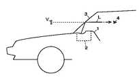
従来より、車両のダッシュボード1に配設された表示装置2が投射する表示光Lをフロントガラス3で運転者4の方向に反射させ、虚像Vを表示するヘッドアップディスプレイがある(図5参照)。表示装置2は、表示器5と反射鏡6とを有しており、この表示器5及び反射鏡6は、上側ケース体7と下側ケース体8とからなるハウジング9に収容されている(図6参照)。表示器5は、液晶表示素子11及びバックライト12有しており、車両速度等を表示する。表示器5が発した表示光Lは、反射鏡6で反射されて、フロントガラス3に投射される。運転者4は、虚像Vを風景に重畳させて視認できる。
【0003】
上側ケース体7には表示光Lが出射する窓部7aが形成されており、この窓部7aには透明カバー13が配設されている。下側ケース体8の底壁には、支持部8a,8bが突出形成されており、この支持部8a,8bに、反射鏡6を保持するホルダー14と、表示器5とが夫々固定されている。また、下側ケース体8には、液晶表示素子11を駆動する駆動回路等が搭載された回路基板15が固定されている。液晶表示素子11は、図示しない可撓性配線部材により回路基板15に電気接続されている。
【0004】
【発明が解決しようとする課題】
しかしながら、窓部7aから入射した太陽光や、表示器5が下向きに発した光の一部L1が、回路基板15の配線パターンで反射され、窓部7aからフロントガラス3に映し出されてゴースト像が発生し、虚像Vの視認の妨げになるという問題があった。
本発明は、この問題に鑑みなされたものであり、太陽光等の外部光や、表示器が発した光が、回路基板に照射される虞がない表示装置を提供するものである。
【0005】
【課題を解決するための手段】
本発明は、前記課題を解決するため、表示器21と、回路基板25と、前記表示器21及び前記回路基板25を収容したハウジング26と、を有し、虚像を表示する表示装置であって、前記回路基板25に光が照射されることを防ぐ遮蔽部材24を設けたものである。
【0006】
また、本発明は、前記表示器21は表示素子27を有し、前記表示素子27を駆動する駆動回路43が前記回路基板25に搭載されているものである。
【0007】
また、本発明は、前記表示器21が発した表示光Lを反射させる反射鏡22と、前記反射鏡22の角度位置を調整する角度位置調整手段23と、を設けたものである。
【0008】
また、本発明は、前記角度位置調整手段23はモータ31を有し、前記モータ31を駆動する駆動回路45が前記回路基板25に搭載されているものである。
【0009】
また、本発明は、前記回路基板25は、前記遮蔽部材24に固定されているものである。
【0010】
また、本発明は、前記遮蔽部材24は、前記表示光Lが通過する開口部24cを有する遮光壁24bを有するものである。
【0011】
【発明の実施の形態】
以下、添付の図面に基いて、本発明を車両用ヘッドアップディスプレイに応用した一実施形態を説明する。図1乃至図3は第一実施形態を示すものである。
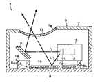
表示装置20は、液晶表示器21(表示器),凹面鏡22(反射鏡),駆動機構23(角度位置調整手段),支持部材24(遮蔽部材),回路基板25及びハウジング26を有している。
【0012】
液晶表示器21は、TFT型の液晶表示素子27(表示素子),リフレクタ28,発光ダイオード29及び硬質配線板30を有している。複数の発光ダイオード29は、互いに近接して配置されており、硬質配線板30に接続されている(図2参照)。リフレクタ28は、内側反射面28aを有する角筒状となっており、発光ダイオード29と液晶表示素子27の間に配置されている。
凹面鏡22は、ポリカーボネート(PC)等の樹脂にアルミニウム(Al)を蒸着させ反射層を形成したものである。凹面鏡22は、液晶表示器21が発した表示光Lを車両のフロントガラスに投射する。
【0013】
駆動機構23は、ステッピングモータ31(モータ),歯車32及びミラーホルダ33を有しており、凹面鏡22を揺動させ、表示光Lの投射方向を調整する。ミラーホルダー33は図示しない弾性係止片を有しており、この弾性係止片により凹面鏡22を固定している。ミラーホルダ33は、ABS等の樹脂からなるものであり、軸部33a及び歯車部33bが一体に形成されている。軸部33aは図示しない軸受部に軸支されており、凹面鏡22及びミラーホルダ33は揺動可能に支持されている。歯車32はステッピングモータ31の回動軸に取付けられており、歯車部33bと噛み合わされている。
【0014】
支持部材24はABS等の樹脂からなるものであり、基部24aの上面側に液晶表示器21及び駆動機構23が固定されている。支持部材24は液晶表示器21から上向きに発せられた光L2を遮る遮光壁24bを有しており、この遮光壁24bには表示光Lが通過する開口部24cが形成されている。支持部材24には、反射率を低減するため、黒色塗装を施すことが望ましい。
回路基板25は、ガラスエポキシ基板に銅箔からなる配線パターンを形成したものであり、基部24aの下面側にビスにより固定されている。回路基板25には後述する駆動回路等が搭載されている。液晶表示器21から下向きに発せられた光L1は基部24aに遮られるため、回路基板25には照射されない。
【0015】
ハウジング26は、PBT等の樹脂からなるものであり、上側ケース体35及び下側ケース体36を有している。上側ケース体35には、表示光Lが出射する窓部35aが形成されており、この窓部35aには透光性カバー37が配設されている。透光性カバー37は透光性樹脂(例えばアクリル)からなるものであり、湾曲形状となっている。下側ケース体36の底壁には支持部36aが突出形成されており、この支持部26aに支持部材24が固定されている。
【0016】
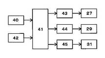
次に、図3に基づいて、表示装置の電気的構成について説明する。40は速度センサであり、この速度センサ40は車両速度を検出し、速度データを制御部41に出力する。42は押ボタンスイッチ等からなる操作手段であり、この操作手段42は、ステッピングモータ31を回動させ凹面鏡22の角度位置を調整するための操作データを制御部41に出力する。
【0017】
制御部41は、CPU,RAM,ROM等から構成されるものであり、駆動回路44を介して発光ダイオード29を点灯させると共に、速度センサ40から入力した速度データに基づいて、駆動回路43を介して液晶表示素子27に車両速度を表示させる。また、制御部41は、操作手段42から入力した操作データに基づいて、駆動回路45を介してステッピングモータ31を駆動する。制御部41及び駆動回路43,44,45は回路基板24に搭載されている。
【0018】
図4は第二実施形態を示す図である。第二実施形態は、反射鏡47及びミラーホルダ48が第一実施形態と相違するだけであるので、同一の箇所には同一の符号を付して、詳細な説明を省略する。
ミラーホルダ48は支持部材24の前面側に固定されている。反射鏡47はミラーホルダ48に両面粘着テープで貼着されている。反射鏡47は、液晶表示器21が発した表示光Lを車両のフロントガラスに投射する。
【0019】
第一,第二実施形態によれば、窓部35aから入射した太陽光や、液晶表示器21から下向きに発せられる光L1が回路基板25に照射されることがなく、回路基板25で反射された光がフロントガラスに投射されてゴースト像が発生する虞がない。また、液晶表示器21から上向きに発せられた光L2は遮光壁24bで遮られるため、窓部35aからフロントガラスに投射されてゴースト像が発生する虞がない。
【0020】
なお、各実施形態の表示器は、液晶表示器21あったが、例えば有機ELパネルを用いた表示器であっても良い。また、各実施形態は、ヘッドアップディスプレイであったが、例えば虚像表示型コンビネーションメータにも応用できることは言うまでもない。
【0021】
【発明の効果】
本発明は、表示器と、回路基板と、前記表示器及び前記回路基板を収容したハウジングと、を有する表示装置であって、前記回路基板に光が照射されることを防ぐ遮蔽部材を設けたものであり、太陽光等の外部光や、表示器が発した光が、回路基板に照射される虞がなく、ゴースト像が発生しない。
【図面の簡単な説明】
【図1】本発明の第一実施形態を示す表示装置の断面図。
【図2】同上実施形態を示す液晶表示器の断面図。
【図3】同上実施形態を示す表示装置のブロック図。
【図4】本発明の第二実施形態を示す表示装置の断面図。
【図5】従来例を示すヘッドアップディスプレイの概略構成図。
【図6】同上従来例を示す表示装置の断面図。
【符号の説明】
21 液晶表示器(表示器)
22 凹面鏡(反射鏡)
23 駆動機構(角度位置調整手段)
24 支持部材(遮蔽部材)
24a 遮光壁
24b 開口部
25 回路基板
26 ハウジング
27 液晶表示素子(表示素子)
31 ステッピングモータ(モータ)
43 駆動回路
45 駆動回路[0001]
TECHNICAL FIELD OF THE INVENTION
The present invention relates to a display device in which a display and a circuit board are housed in a housing.
[0002]
[Prior art]
Conventionally, there is a head-up display that reflects a display light L projected by a display device 2 disposed on a dashboard 1 of a vehicle toward a
[0003]
A window 7a from which the display light L is emitted is formed in the
[0004]
[Problems to be solved by the invention]
However, the sunlight entering from the window 7a or a part L1 of the light emitted downward by the
The present invention has been made in view of this problem, and provides a display device in which external light such as sunlight or light emitted from a display device is not likely to be irradiated on a circuit board.
[0005]
[Means for Solving the Problems]
The present invention provides a display device for displaying a virtual image, comprising: a
[0006]
In the present invention, the
[0007]
Further, the present invention is provided with a reflecting
[0008]
In the present invention, the angular position adjusting means 23 has a
[0009]
Further, in the present invention, the
[0010]
Further, in the present invention, the
[0011]
BEST MODE FOR CARRYING OUT THE INVENTION
Hereinafter, an embodiment in which the present invention is applied to a head-up display for a vehicle will be described with reference to the accompanying drawings. 1 to 3 show a first embodiment.
The
[0012]
The
The
[0013]
The
[0014]
The
The
[0015]
The
[0016]
Next, an electrical configuration of the display device will be described with reference to FIG. A
[0017]
The
[0018]
FIG. 4 is a diagram showing the second embodiment. In the second embodiment, since the reflecting
The
[0019]
According to the first and second embodiments, the sunlight incident from the
[0020]
Although the display device of each embodiment is the liquid
[0021]
【The invention's effect】
The present invention is a display device including a display, a circuit board, and a housing accommodating the display and the circuit board, wherein a shielding member that prevents the circuit board from being irradiated with light is provided. Therefore, there is no possibility that external light such as sunlight or light emitted from a display device is irradiated on the circuit board, and no ghost image is generated.
[Brief description of the drawings]
FIG. 1 is a sectional view of a display device showing a first embodiment of the present invention.
FIG. 2 is a cross-sectional view of the liquid crystal display showing the embodiment.
FIG. 3 is a block diagram of a display device showing the embodiment.
FIG. 4 is a sectional view of a display device showing a second embodiment of the present invention.
FIG. 5 is a schematic configuration diagram of a head-up display showing a conventional example.
FIG. 6 is a cross-sectional view of a display device showing a conventional example.
[Explanation of symbols]
21 Liquid crystal display (display)
22 Concave mirror (reflection mirror)
23 drive mechanism (angular position adjusting means)
24 Supporting member (shielding member)
24a
31 Stepping Motor (Motor)
43
Claims (7)
Translated fromJapanese前記回路基板に光が照射されることを防ぐ遮蔽部材を設けたことを特徴とする表示装置。A display device, comprising a circuit board, a housing that houses the display device and the circuit board, and a display device that displays a virtual image,
A display device, comprising a shielding member for preventing the circuit board from being irradiated with light.
Priority Applications (1)
| Application Number | Priority Date | Filing Date | Title |
|---|---|---|---|
| JP2002172544AJP2004017708A (en) | 2002-06-13 | 2002-06-13 | Display device |
Applications Claiming Priority (1)
| Application Number | Priority Date | Filing Date | Title |
|---|---|---|---|
| JP2002172544AJP2004017708A (en) | 2002-06-13 | 2002-06-13 | Display device |
Publications (1)
| Publication Number | Publication Date |
|---|---|
| JP2004017708Atrue JP2004017708A (en) | 2004-01-22 |
Family
ID=31172074
Family Applications (1)
| Application Number | Title | Priority Date | Filing Date |
|---|---|---|---|
| JP2002172544APendingJP2004017708A (en) | 2002-06-13 | 2002-06-13 | Display device |
Country Status (1)
| Country | Link |
|---|---|
| JP (1) | JP2004017708A (en) |
Cited By (11)
| Publication number | Priority date | Publication date | Assignee | Title |
|---|---|---|---|---|
| JP2007180141A (en)* | 2005-12-27 | 2007-07-12 | Nippon Seiki Co Ltd | Display apparatus |
| JP2009073461A (en)* | 2007-08-29 | 2009-04-09 | Nippon Seiki Co Ltd | Head-up display device |
| JP2010175574A (en)* | 2009-01-27 | 2010-08-12 | Nippon Seiki Co Ltd | Head-up display device |
| JP2010197987A (en)* | 2009-01-27 | 2010-09-09 | Nippon Seiki Co Ltd | Head-up display |
| JP2010208565A (en)* | 2009-03-12 | 2010-09-24 | Nippon Seiki Co Ltd | Headup display device |
| JP2012063524A (en)* | 2010-09-15 | 2012-03-29 | Nippon Seiki Co Ltd | Vehicular head-up display device |
| KR101764939B1 (en)* | 2009-12-25 | 2017-08-03 | 닛폰 세이키 가부시키가이샤 | Lighting device |
| JP2017171041A (en)* | 2016-03-22 | 2017-09-28 | 日本精機株式会社 | Display device |
| US10118489B2 (en) | 2014-11-17 | 2018-11-06 | Nippon Seiki Co., Ltd. | Head-up display device |
| JP2019139128A (en)* | 2018-02-14 | 2019-08-22 | 日本精機株式会社 | Head-up display device |
| JP2020189626A (en)* | 2016-03-22 | 2020-11-26 | 日本精機株式会社 | Display device |
- 2002
- 2002-06-13JPJP2002172544Apatent/JP2004017708A/enactivePending
Cited By (12)
| Publication number | Priority date | Publication date | Assignee | Title |
|---|---|---|---|---|
| JP2007180141A (en)* | 2005-12-27 | 2007-07-12 | Nippon Seiki Co Ltd | Display apparatus |
| JP2009073461A (en)* | 2007-08-29 | 2009-04-09 | Nippon Seiki Co Ltd | Head-up display device |
| JP2010175574A (en)* | 2009-01-27 | 2010-08-12 | Nippon Seiki Co Ltd | Head-up display device |
| JP2010197987A (en)* | 2009-01-27 | 2010-09-09 | Nippon Seiki Co Ltd | Head-up display |
| JP2010208565A (en)* | 2009-03-12 | 2010-09-24 | Nippon Seiki Co Ltd | Headup display device |
| KR101764939B1 (en)* | 2009-12-25 | 2017-08-03 | 닛폰 세이키 가부시키가이샤 | Lighting device |
| JP2012063524A (en)* | 2010-09-15 | 2012-03-29 | Nippon Seiki Co Ltd | Vehicular head-up display device |
| US10118489B2 (en) | 2014-11-17 | 2018-11-06 | Nippon Seiki Co., Ltd. | Head-up display device |
| JP2017171041A (en)* | 2016-03-22 | 2017-09-28 | 日本精機株式会社 | Display device |
| JP2020189626A (en)* | 2016-03-22 | 2020-11-26 | 日本精機株式会社 | Display device |
| JP2019139128A (en)* | 2018-02-14 | 2019-08-22 | 日本精機株式会社 | Head-up display device |
| JP7010045B2 (en) | 2018-02-14 | 2022-02-10 | 日本精機株式会社 | Head-up display device |
Similar Documents
| Publication | Publication Date | Title |
|---|---|---|
| JP4883283B2 (en) | Display device | |
| JP5919724B2 (en) | Head-up display device for vehicle | |
| JP2008070504A (en) | Display | |
| JP2005331624A (en) | Head-up display device for vehicle | |
| JP4831474B2 (en) | Head-up display device for vehicle | |
| JP6024035B2 (en) | In-vehicle display device | |
| JP2010152025A (en) | Display device | |
| JP4941070B2 (en) | Vehicle display device | |
| JP2010113197A (en) | Head-up display device | |
| JP2007065011A (en) | Head-up display device | |
| JP2009288388A (en) | Display device | |
| JP2013224068A (en) | Vehicle head-up display device | |
| JP2004017708A (en) | Display device | |
| JP2003080974A (en) | Vehicle instrument | |
| JP2006011168A (en) | Head-up display device for vehicle | |
| JP5556019B2 (en) | Head-up display device | |
| JP2009067352A (en) | Head-up display device | |
| JP2010132207A (en) | Head-up display device | |
| JPH11278100A (en) | Display device | |
| JP2008003355A (en) | Display apparatus | |
| JP2021021829A (en) | Head-up display device | |
| JP2004317906A (en) | Display device | |
| JP5283325B2 (en) | Light emitting device | |
| JP2010243758A (en) | Head-up display | |
| WO2012036116A1 (en) | Display device |
Legal Events
| Date | Code | Title | Description |
|---|---|---|---|
| A621 | Written request for application examination | Free format text:JAPANESE INTERMEDIATE CODE: A621 Effective date:20050311 | |
| A131 | Notification of reasons for refusal | Free format text:JAPANESE INTERMEDIATE CODE: A131 Effective date:20070921 | |
| A521 | Request for written amendment filed | Free format text:JAPANESE INTERMEDIATE CODE: A523 Effective date:20071029 | |
| A02 | Decision of refusal | Free format text:JAPANESE INTERMEDIATE CODE: A02 Effective date:20080303 |