JP2004016333A - Catheter for extradural anesthesia, and electrostimulator using the catheter for extradural anesthesia - Google Patents
Catheter for extradural anesthesia, and electrostimulator using the catheter for extradural anesthesiaDownload PDFInfo
- Publication number
- JP2004016333A JP2004016333AJP2002172695AJP2002172695AJP2004016333AJP 2004016333 AJP2004016333 AJP 2004016333AJP 2002172695 AJP2002172695 AJP 2002172695AJP 2002172695 AJP2002172695 AJP 2002172695AJP 2004016333 AJP2004016333 AJP 2004016333A
- Authority
- JP
- Japan
- Prior art keywords
- catheter
- electrodes
- tube
- unit
- distal end
- Prior art date
- Legal status (The legal status is an assumption and is not a legal conclusion. Google has not performed a legal analysis and makes no representation as to the accuracy of the status listed.)
- Pending
Links
- 206010002091AnaesthesiaDiseases0.000titleclaimsabstractdescription12
- 230000037005anaesthesiaEffects0.000titleclaimsabstractdescription12
- 239000000243solutionSubstances0.000claimsabstractdescription71
- 230000000638stimulationEffects0.000claimsabstractdescription49
- 239000007924injectionSubstances0.000claimsabstractdescription30
- 238000002347injectionMethods0.000claimsabstractdescription30
- 239000003814drugSubstances0.000claimsdescription49
- 229940079593drugDrugs0.000claimsdescription47
- 238000002692epidural anesthesiaMethods0.000claimsdescription34
- 230000000763evoking effectEffects0.000claimsdescription14
- 239000000126substanceSubstances0.000claimsdescription14
- 210000005036nerveAnatomy0.000claimsdescription13
- 230000004936stimulating effectEffects0.000claimsdescription13
- 238000002847impedance measurementMethods0.000claimsdescription11
- 241001269524DuraSpecies0.000claimsdescription9
- 230000002093peripheral effectEffects0.000claimsdescription5
- 230000003321amplificationEffects0.000claimsdescription3
- 239000007788liquidSubstances0.000claimsdescription3
- 238000003199nucleic acid amplification methodMethods0.000claimsdescription3
- 210000001519tissueAnatomy0.000description18
- 210000002330subarachnoid spaceAnatomy0.000description14
- 210000001175cerebrospinal fluidAnatomy0.000description12
- 238000000034methodMethods0.000description11
- 230000003444anaesthetic effectEffects0.000description9
- 210000003205muscleAnatomy0.000description7
- 210000004556brainAnatomy0.000description6
- 238000012986modificationMethods0.000description5
- 230000004048modificationEffects0.000description5
- 208000002193PainDiseases0.000description4
- 238000003780insertionMethods0.000description4
- 230000037431insertionEffects0.000description4
- 230000036407painEffects0.000description4
- 238000010586diagramMethods0.000description3
- 238000007913intrathecal administrationMethods0.000description3
- 239000004698PolyethyleneSubstances0.000description2
- 230000004064dysfunctionEffects0.000description2
- 230000000694effectsEffects0.000description2
- 239000000463materialSubstances0.000description2
- 238000005259measurementMethods0.000description2
- 238000012544monitoring processMethods0.000description2
- 230000004118muscle contractionEffects0.000description2
- 239000002504physiological saline solutionSubstances0.000description2
- BASFCYQUMIYNBI-UHFFFAOYSA-NplatinumChemical compound[Pt]BASFCYQUMIYNBI-UHFFFAOYSA-N0.000description2
- -1polyethylenePolymers0.000description2
- 229920000573polyethylenePolymers0.000description2
- 208000000059DyspneaDiseases0.000description1
- 206010013975DyspnoeasDiseases0.000description1
- 206010019233HeadachesDiseases0.000description1
- 230000036592analgesiaEffects0.000description1
- 210000000576arachnoidAnatomy0.000description1
- 230000036772blood pressureEffects0.000description1
- 210000001124body fluidAnatomy0.000description1
- 239000010839body fluidSubstances0.000description1
- 210000003298dental enamelAnatomy0.000description1
- 230000000249desinfective effectEffects0.000description1
- 238000003745diagnosisMethods0.000description1
- 238000002695general anesthesiaMethods0.000description1
- 231100000869headacheToxicity0.000description1
- 210000003041ligamentAnatomy0.000description1
- 238000002690local anesthesiaMethods0.000description1
- 210000001365lymphatic vesselAnatomy0.000description1
- 229910052697platinumInorganic materials0.000description1
- 230000002980postoperative effectEffects0.000description1
- 238000003825pressingMethods0.000description1
- 238000002693spinal anesthesiaMethods0.000description1
- 210000000278spinal cordAnatomy0.000description1
- 229910001220stainless steelInorganic materials0.000description1
- 239000010935stainless steelSubstances0.000description1
- 208000024891symptomDiseases0.000description1
- 210000003462veinAnatomy0.000description1
- 238000004804windingMethods0.000description1
Images


Landscapes
- Media Introduction/Drainage Providing Device (AREA)
- Electrotherapy Devices (AREA)
- Measurement And Recording Of Electrical Phenomena And Electrical Characteristics Of The Living Body (AREA)
Abstract
Description
Translated fromJapanese【0001】
【発明の属する技術分野】
本発明は、硬膜外腔に麻酔薬等を注入する硬膜外麻酔用カテーテル、および該硬膜外麻酔用カテーテルを用いる電気刺激装置に関する。
【0002】
【従来の技術】
従来から、各種の手術時における麻酔や、術後鎮痛、ペインクリニック(痛みの治療)等において硬膜外麻酔が広く行われている。この硬膜外麻酔は、脊髄を覆うくも膜および硬膜の外側にある「硬膜外腔」内にカテーテルを挿入して麻酔薬を注入する麻酔法である。この硬膜外腔はリンパ管、静脈、硬膜神経根を含んでおり、さらにその空間は脂肪で満たされている。また、硬膜の内側には「くも膜下腔」と呼ばれる空間があり、その空間は髄液で満たされている。
【0003】
硬膜外麻酔用カテーテルを用いた硬膜外麻酔は、概略的には以下の手順で行われる。
【0004】
まず、患者の背中側から椎骨極突起間に痛み止めの麻酔薬を注射し、同じく患者の背中側から硬膜外針をその先端が硬膜外腔内に達するまで刺入する。次に、カテーテルを硬膜外針内に挿通して硬膜外腔内に挿入し、カテーテルを硬膜外針の先端から4〜5cmほど突出させる。その後、カテーテルを通じて硬膜外腔内に麻酔薬等の薬液を注入する。
【0005】
【発明が解決しようとする課題】
体内に挿入されたカテーテルの薬液注入部(多くの場合は先端部)がどの位置にあるかは、目視で確認することはできない。所望の麻酔効果を得るためには所定の部位に正確に薬液を注入する必要があり、そのためには薬液を注入するカテーテルの先端部がどの位置にあるかを正しく認識する必要がある。
【0006】
特に、カテーテルの先端が硬膜を貫通してくも膜下腔内に達している場合には、そのまま薬液を注入すると硬膜外麻酔ではなく全身麻酔である脊椎麻酔を行うことになる。この場合、術後に頭痛が発生したり、あるいは術中に呼吸困難等の深刻な事態が発生するおそれがあるので、くも膜下腔内に薬液を注入することは避けなければならない。
【0007】
カテーテルの先端部がくも膜下腔内に達しているかどうかを確認する手法としては、カテーテルを通じて髄液が逆流してくるか否かをもって判断する手法がある。しかしながら、その手法では、カテーテル内に麻酔薬が充填されている場合には髄液が逆流し難いため、髄液が逆流してきたかどうかを判断することは困難である。
【0008】
そこで本発明は、薬液注入部等が体内のどの位置にあるか、さらには薬液注入部等がくも膜下腔腔内に侵入していないかを認識することができる硬膜外麻酔用カテーテル、および該硬膜外麻酔用カテーテルを用いる電気刺激装置を提供することを目的とする。
【0009】
【課題を解決するための手段】
上記目的を達成するため、本発明の硬膜外麻酔用カテーテルは、硬膜外腔内に薬液を注入する硬膜外麻酔用カテーテルであって、薬液を通す内腔と、該内腔を通して運ばれた前記薬液を体内に注入させる薬液注入部とを有する管と、前記管の外周面に前記管の長さ方向に所定の間隔をおいて設けられた2つの電極からなり、前記2つの電極間に位置する組織に刺激電流を流すとともに、前記2つの電極間に位置する組織にインピーダンス測定電流を流して前記組織のインピーダンス値を測定するための双極電極とを有している。
【0010】
上記本発明の硬膜外麻酔用カテーテルによれば、双極電極をなす2つの電極間に刺激電流を流すことで、その双極電極の近傍の筋肉組織を刺激して筋収縮させることができる。これにより、術者は患者の筋収縮した部位を皮膚の上から目視で確認することで、カテーテルの双極電極が設けられている部分が患者の体内のどの部位に位置しているかを認識することができる。
【0011】
また、硬膜外腔内を満たす脂肪のインピーダンス値は、硬膜内に形成されたくも膜下腔内を満たす髄液のインピーダンス値の数倍の大きさを有している。そのため、双極電極で測定された組織のインピーダンス値が所定の値よりも低いか否かを判断することにより、カテーテルの双極電極が設けられている部分が硬膜外腔内にあるかくも膜下腔内にあるかを識別することができる。
【0012】
前記薬液注入部と前記双極電極は前記管の先端部に設けられている構成としてもよい。この構成では、双極電極が薬液注入部の近くに配置されることから、カテーテルの薬液注入部が患者の体内のどの部位に位置しているかを認識し、さらにその薬液注入部が硬膜外腔内にあるかくも膜下腔内にあるかを識別することが可能になる。
【0013】
また、前記薬液注入部は前記管の先端部に設けられており、前記双極電極は前記管の先端部から終端側に所定の距離だけ離れた位置に設けられている構成としてもよい。このように構成されたカテーテルは、硬膜外腔内にその先端部を頭側に向けて挿入すると、薬液注入部が設けられた先端部の方が双極電極が設けられている部分よりも高位(脳側)に配置される。そのため、先端部から硬膜外腔内に少量の薬液を注入して高位部に軽い麻酔をかけた後に双極電極から刺激電流を流すことで、電気刺激によって患者に与える不快感を軽減することができる。
【0014】
さらに、他の前記双極電極が前記管の先端部にも設けられている構成とすることより、体内における薬液注入部の位置を検出することができ、薬液を所望の部位に正確に注入することが可能になる。
【0015】
あるいは、前記双極電極は前記管の先端部に設けられており、前記薬液注入部は前記管の先端部から終端側に所定の距離だけ離れた位置に設けられている構成としてもよい。このように構成されたカテーテルは、硬膜外腔内にその先端を頭側に向けて挿入すると、双極電極が設けられた先端部の方が薬液注入部よりも高位(脳側)に配置される。そのため、先端部の双極電極から刺激電流を流し、その近傍の神経機能をモニターしながら薬液注入部から薬液を注入することにより、薬液注入部から注入された薬液による麻酔の影響が高位(脳側)の神経に及ぶことを抑えることができる。
【0016】
さらに、他の前記双極電極が前記管の前記薬液注入部が設けられている位置の近傍にも設けられている構成としてもよい。これにより、体内における薬液注入部の位置を検出することができ、薬液を所望の部位に正確に注入することが可能になる。
【0017】
また、前記所定の距離は略20cmである構成としてもよい。
【0018】
さらに、前記2つの電極間の所定の間隔は略1cmである構成としてもよい。
【0019】
また、本発明の電気刺激装置は、上記本発明の硬膜外麻酔用カテーテルを用いる電気刺激装置であって、前記硬膜外麻酔用カテーテルが備える前記双極電極を成す前記2つの電極間に刺激電流を流す電気刺激部と、前記2つの電極間にインピーダンス測定電流を流して、前記2つの電極間に位置する組織のインピーダンス値を測定するインピーダンス測定部とを有している。
【0020】
上記本発明の電気刺激装置によれば、双極電極をなす2つの電極間に電気刺激部から刺激電流を流し、その双極電極の近傍の筋肉組織を刺激して筋収縮させることにより、カテーテルの双極電極が設けられている部分が患者の体内のどの部位に位置しているかを認識することができる。
【0021】
また、硬膜外腔内を満たす脂肪のインピーダンス値は、硬膜内に形成されたくも膜下腔内を満たす髄液のインピーダンス値の数倍の大きさを有していることから、インピーダンス測定部によって測定された2つの電極間の組織のインピーダンス値が所定の値よりも低いか否かを判断することにより、カテーテルの双極電極が設けられている部分が硬膜外腔内にあるかくも膜下腔内にあるかを識別することができる。
【0022】
さらに、前記インピーダンス値が所定の下限値よりも小さい場合と所定の上限値よりも大きい場合に警告を発する警告部をさらに有している構成としてもよい。
【0023】
上述のように、硬膜外腔内を満たす脂肪のインピーダンス値は、硬膜内に形成されたくも膜下腔内を満たす髄液のインピーダンス値の数倍の大きさを有している。そのため、測定対象の組織が脂肪か髄液かを区別できるインピーダンス値を下限値として設定すれば、術者は、測定されたインピーダンス値がその下限値よりも小さい場合に発せられる警告によって、カテーテルの双極電極が設けられている部分がくも膜下腔内にあることを認識することができる。
【0024】
一方、脂肪のインピーダンス値よりも大きい値を上限値として設定すれば、術者は、測定されたインピーダンス値がその上限値よりも大きい場合に発せられる警告によって、カテーテルの双極電極に接続されている導電線が断線している可能性を認識することができる。
【0025】
また、前記電気刺激部は、前記刺激電流を制御する外部の制御装置が接続される外部制御入力部を備えている構成としてもよい。これにより、術者が制御装置を操作することにより、刺激電流の電流値、パルス幅、および頻度等を術者の所望に応じて変化させることができる。
【0026】
さらに、前記電気刺激部は、前記2つの電極間に流す刺激電流の極性を切り替えることができるように構成されていてもよい。カテーテルの挿入方向、すなわちその先端が硬膜外腔内に頭側を向いて挿入されているか、あるいは尾側を向いて挿入されているかによって、2つの電極の神経の上位側に対する配置が逆になるので、各電極に印加すべき刺激電流の極性が異なる。そのため術者は、カテーテルの挿入方向に応じて、2つの電極間に流す刺激電流の極性を切り替えることによって、良好に電気刺激を行うことができる。
【0027】
さらに、前記電気刺激部から流された刺激電流によって神経が刺激されることで誘発された誘発電位を前記双極電極を成す前記2つの電極で検出し、前記誘発電位を増幅して外部に出力する誘発電位増幅出力部を有している構成としてもよい。この構成によれば、神経に刺激電流を加えた後に出現する誘発電位を増幅して外部装置に出力し、その外部装置で誘発電位の波形等を解析することによって、神経路の機能障害等を診断することが可能になる。
【0028】
【発明の実施の形態】
次に、本発明の実施形態について図面を参照して説明する。
【0029】
図1は本発明に係る硬膜外麻酔用カテーテルの一実施形態を示す図であり、同図(a)はその先端部付近を示す軸方向断面図、同図(b)は同図(a)のA−A線における断面図である。
【0030】
図1に示すように、本実施形態の硬膜外麻酔用カテーテル(以下、「カテーテル」という。)は、ポリエチレン等の絶縁性および可撓性を有する素材からなり、先端が開口している外管1と、外管1内に配設された、同じくポリエチレン等の絶縁性および可撓性を有する素材からなり、先端が開口している内管2とを有している。内管2の外径寸法は外管1の内径寸法よりも小さく、したがって内管2の外周と外管1の内周との間には隙間が形成されている。外管1の外径寸法は約1mmである。なお、内管2が外管1の外に突出したり、あるいは外管1の中に引き込まれたりしないように、内管2は少なくともその一部が外管1の内周面に接着や融着等の手段によって固定されている。
【0031】
外管1の先端部には、一組の双極電極を成す第1の電極3と第2の電極4が外管1の外周を取り囲むように設けられている。両電極3,4は外管1の長さ方向に互いに1cmの間隔をおいて配設されている。各電極3,4は、例えば、ステンレス鋼や白金等からなる極めて細い導電性のワイヤーを外管1の外周面上に巻き付けることによって形成することができる。
【0032】
さらに、外管1と内管2との隙間空間には、第1の電極3と第2の電極4にそれぞれ接続された第1の導電線5と第2の導電線6が配設されている。各導電線5,6は、それぞれ外管1の壁部を貫通して各電極3,4に接続されている。これらの導電線5,6はエナメル等の絶縁性被膜によって被覆されており、カテーテル内で導電線5,6同士が接触しても短絡しないようになっている。なお、各導電線5,6の後端は、後述する電気刺激装置10の接続部11(図2参照)に任意の接続手段によって接続される。
【0033】
このように構成されたカテーテルによれば、カテーテルを患者の体内に挿入した後に内管2に麻酔薬等の薬液を通して、内管2の先端の薬液注入部7から体内に薬液を注入することができる。また、このカテーテルによれば、導電線5,6を介して電極3,4間に刺激電流であるパルス電流を印加することで、電極3,4の近傍に位置する筋肉を局部的に刺激して収縮させることが可能である。さらに、導電線5,6を介して電極3,4間に所定の定電流、所定周波数の電流を流すことで、組織(筋組織、脂肪組織、体液等)を通って電極3,4間を流れる電流のインピーダンス値を測定することが可能である。
【0034】
なお、上記では外管1内に薬液注入用の内管2を備えた二重管構造の例を挙げて説明したが、本発明によるカテーテルは必ずしも二重管構造である必要はなく、内管2を備えずに外管1の内部に薬液を直接通す構成としてもよい。ただしこの場合には、導電線5,6が薬液中に浸されることになるので、導電線5,6同士が薬液を介して短絡したり漏電を起こしたりすることがないように、導電線5,6はより確実に被覆されている必要がある。
【0035】
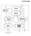
図2は、図1に示したカテーテルを用いる電気刺激装置の概略構成を示すブロック図である。また、図3は図2に示した電気刺激装置の表示部や操作部等が設けられた正面外観を示す概略図である。
【0036】
図2に示すように、本実施形態の電気刺激装置10は、図1に示したカテーテルの各導電線5,6の後端部が電気的に接続される接続部11と、接続部11を介して各導電線5,6に接続され、電極3,4間にパルス電流を印加することで、電極3,4が位置する近傍の筋肉を局部的に刺激して収縮させる電気刺激部13と、同じく接続部11を介して各導電線5,6に接続され、電極3,4間に所定の定電流値、所定周波数の電流を流すことで、組織を通って電極3,4間を流れる電流のインピーダンス値を測定するインピーダンス測定部12とを備えている。
【0037】
電気刺激部13はパルス電流を出力するパルス電流出力部(不図示)を有している。パルス電流出力部は、例えば、1kΩのインピーダンスに対して最大で20mAの定電流を、パルス幅を0.1msec、頻度を1Hzで出力することができるように構成されている。
【0038】
さらに、この電気刺激部13には、パルス電流出力部から出力するパルス電流を制御するためにコンピュータ等の外部の制御装置が接続される外部制御入力端子(不図示)が設けられている。この制御装置にパルス電流の種々のパターンを記憶させておけば、術者は刺激を加えようとする部位に応じてそれらのパターンの中から適切なものを選択するだけで、所望のパルス電流を印加することができる。
【0039】
一方、インピーダンス測定部12は、インピーダンス測定電流として所定の定電流値で所定周波数の電流を流す電流出力部(不図示)と、その電流出力部から出力された測定電流が電極3,4間に位置する組織を流れるときのインピーダンス値を測定する測定部(不図示)とを有している。電流出力部は、インピーダンス測定電流として、例えば電流値が100μAで周波数が1kHzの電流を出力することができるようになっている。
【0040】
上述したように、硬膜外麻酔用カテーテルが薬液を注入する硬膜外腔は脂肪で満たされており、硬膜内の空間であるくも膜下腔は髄液で満たされている。髄液のインピーダンス値は生理食塩水のインピーダンス値である60Ω・cmとほぼ同じであるのに対し、脂肪のインピーダンス値は少なくともこの数倍の大きさを有している。そのため、測定対象の組織が脂肪か髄液かを区別できるインピーダンス値を下限値として設定すれば、電極3,4間にある組織のインピーダンス値を測定することにより、その値がその下限値よりも小さいか否かによって、カテーテルの先端部が硬膜外腔内にあるかくも膜下腔内にあるかを判断することができる。
【0041】
また、インピーダンス測定部12には警告部16が接続されている。この警告部16は、測定されたインピーダンス値が上記の所定の下限値よりも小さいときに、警告音を発したり、警告ランプが点灯したりするように構成されている。警告部16によって、測定されたインピーダンス値が上記の下限値よりも低いことを示す警告が発せられた場合には、カテーテルの先端部がくも膜下腔内にある可能性が高いことを意味する。
【0042】
この警告部16はまた、導電線5,6が断線しているかどうかを判断するために、測定部で測定された電極3,4間のインピーダンス値がある所定の上限値よりも大きい場合にも警告を発するように構成されている。これは、導電線5,6が断線していると、たとえカテーテルの先端部がくも膜下腔内にある場合であっても測定されるインピーダンス値は高いままであり、カテーテルの先端部がくも膜下腔内にあることを認識することができないためである。
【0043】
これらのインピーダンス測定部12と電気刺激部13には操作部14が接続されている。操作部14は、図3に示すように、インピーダンス測定部12から出力するインピーダンス測定電流の電流値や電気刺激部13から出力するパルス電流の電流値等を変えることができる強度調節つまみ22と、インピーダンス測定部12や電気刺激部13から出力する各電流の極性を切り替えるスイッチ23とを備えている。術者は、導電線5,6を介して電極3,4に流す電流の極性を、そのスイッチ23によって切り替えることができる。
【0044】
さらに、インピーダンス測定部12と電気刺激部13には表示部15が接続されている。この表示部は、インピーダンス測定部12から出力するインピーダンス測定電流の電流値や電気刺激部13から出力するパルス電流の電流値を表示する電流値表示部20と、インピーダンス測定部12で測定したインピーダンス値を表示する抵抗値表示部21とを有している。
【0045】
さらに、本実施形態の電気刺激装置10は、神経が電気刺激部13から流されたパルス電流によって刺激されることで誘発された誘発電位を増幅して外部に出力する誘発電位増幅出力部17を有している。その誘発電位はカテーテルの両電極3,4によって検出される。誘発電位は神経に刺激電流を加えた後に出現し、その波形等を外部の装置で解析することによって神経路の機能障害等を診断することができる。
【0046】
この電気刺激装置10は、例えば電源として電池を用いることができる。これにより、電気刺激装置10の小型化を図ることができ、また、術中に電気刺激装置10を移動させることができることから、カテーテルの操作性が向上する。さらに、上記の外部制御入力端子(不図示)および誘発電位増幅部17を含む電気刺激装置10の電気回路は、患者に不用意な電流が流れ込まないように電気的に他から絶縁されている。
【0047】
次に、図4を参照して、本実施形態のカテーテルおよび電気刺激装置の動作、すなわち本実施形態のカテーテルおよび電気刺激装置を用いた硬膜外麻酔方法を説明する。図4は、硬膜外腔内に図1に示したカテーテルを挿入する手順を説明するための図である。
【0048】
硬膜外麻酔を行うには、まず、患者の背中側の皮膚面を消毒した後に、背中側から椎骨極突起間に痛み止めの麻酔薬を注射して局部麻酔を行う(ステップ1)。
【0049】
続いて、その局部から、硬膜外針(tuohy針)をその先端が硬膜外腔内に達するまで刺入する(ステップ2)。このとき、まずは硬膜外針を黄色靱帯の抵抗を感じるところまで刺入する。次に、硬膜外針のマンドリンを抜き、5〜10mlのシリンジに2〜3ml程度の生理食塩水を入れて硬膜外針に結合し、抵抗が急激に消失するまで、シリンジの内筒に圧力をかけながらゆっくりと硬膜外針をさらに刺入させる。抵抗が急激に消失すると、硬膜外針の先端は硬膜外腔内に到達している(図4(a)参照)。
【0050】
次に、図4(b)に示すようにカテーテルを硬膜外針内に挿通して硬膜外腔内に挿入し、電気刺激装置10のインピーダンス測定部12を作動させてカテーテルの電極3,4間に位置する組織のインピーダンス値を測定しながら、カテーテルの先端部を硬膜外針の先端から4〜5cmほど突出させる(ステップ3)。このとき、測定されたインピーダンス値が髄液のインピーダンス値を識別できる下限値よりも高く、かつ導電線5,6が断線していることを示す上限値よりも低ければ、カテーテルの先端部が硬膜外腔内にあることを確認することができる。
【0051】
続いて、電気刺激装置10の電気刺激部13を作動させてカテーテルの電極3,4間にパルス電流を流し、カテーテルの先端部近傍の筋肉を収縮させることによって、体内におけるカテーテルの先端部の位置を皮膚の上から目視にて確認する(ステップ4)。カテーテルを体内に挿入したときに、カテーテルが体内で屈曲したり反転したりして、その先端部が所望の位置に正しく配置されていないこともある。そのため、このようにしてカテーテルの先端部の位置を確認することは、薬液を所望の部位に正確に注入する上で重要である。
【0052】
最後に、再び電気刺激装置10のインピーダンス測定部12を作動させてカテーテルの電極3,4間に位置する組織のインピーダンス値を測定し、カテーテルの先端部が硬膜外腔内にあることを確認した上で、必要量の薬液をカテーテルを通して硬膜外腔内に注入する(ステップ5)。このとき、必要量の薬液を注入する前に薬液を少量だけ注入して血圧低下や患者の症状を観察し、麻酔薬がくも膜下腔内に注入されていないことを確認することが好ましい。
【0053】
なお、カテーテルの挿入方向、すなわちその先端が頭側を向いて硬膜外腔内に挿入されているか、あるいは尾側を向いて挿入されているかによって、神経の上位側に対する各電極3,4の配置が逆になるので、電極3,4に印加すべき刺激電流の極性が異なる。そのため、術者は、カテーテルの挿入方向に応じて電気刺激装置10の極性切り替えスイッチ23を操作して、適正な極性の刺激電流を印加することが望ましい。
【0054】
(変形例)
図5は本実施形態の硬膜外麻酔用カテーテルの変形例を示す断面図である。
【0055】
図5(a)に示すカテーテルは、先端部が閉じられている管31と、図1に示すカテーテルと同様に先端部に互いに約1cmの間隔をおいて設けられた一組の双極電極を成す第1および第2の電極32,33とを有している。さらに、管31の先端から終端側に約20cmの部分には、管31の内部を通して供給されてきた薬液を体内に注入するための薬液注入部36を成す穴が形成されている。第1の電極32には第1の導電線34が接続され、第2の電極33には第2の導電線35が接続されている。これらの導電線34,35も、図1に示した導電線5,6と同様に絶縁性膜によって表面が被覆されている。
【0056】
このように構成されたカテーテルは、硬膜外腔内にその先端を頭側に向けて挿入すると、双極電極32,33が設けられた先端部の方が薬液注入部36よりも高位(脳側)に配置される。そのため、先端部の双極電極32,33から刺激電流を流し、その近傍の神経機能をモニターしながら薬液注入部36から薬液を注入することにより、薬液注入部36から注入された薬液による麻酔の影響が高位(脳側)の神経に及ぶことを抑えることができる。
【0057】
本変形例のカテーテルは、図5(b)に示すように、上述した構成に加えて、他の一組の双極電極を成す第3および第4の電極37,38を薬液注入部36の近傍に備えていてもよい。なお、これらの電極37,38にも、第3および第4の導電線39,40がそれぞれ接続されている。
【0058】
この構成によれば、薬液注入部36近傍の電極37,38を用いて薬液注入部36の位置を検出することができるので、薬液を所望の位置に正確に注入することも可能になる。
【0059】
図6は本実施形態の硬膜外麻酔用カテーテルの他の変形例を示す断面図である。
【0060】
図6(a)に示すカテーテルは、先端部が開口している管51と、管51の先端から終端側に約20cmの部分に互いに約1cmの間隔をおいて設けられた一組の双極電極を成す第1および第2の電極52,53とを有している。第1の電極52には第1の導電線54が接続され、第2の電極53には第2の導電線55が接続されている。これらの導電線54,55も、図1に示した導電線5,6と同様に絶縁性膜によって表面が被覆されている。
【0061】
このように構成されたカテーテルは、硬膜外腔内にその先端を頭側に向けて挿入すると、薬液注入部56が設けられた先端部の方が双極電極52,53が設けられている部分よりも高位(脳側)に配置される。そのため、先端部から硬膜外腔内に少量の薬液を注入して高位部に軽い麻酔をかけた後に双極電極32,33から刺激電流を流すことで、電気刺激によって患者に与える不快感を軽減することができる。
【0062】
本変形例のカテーテルは、図6(b)に示すように、上述した構成に加えて、他の一組の双極電極を成す第3および第4の電極57,58を先端部に備えていてもよい。なお、これらの電極57,58にも、第3および第4の導電線59,60がそれぞれ接続されている。
【0063】
この構成によれば、電極37,38を用いて先端部(薬液注入部56)の位置を検出することができるので、薬液を所望の位置に正確に注入することも可能になる。
【0064】
【発明の効果】
以上説明したように、本発明は、硬膜外麻酔用カテーテルの管の外周面に、管の長さ方向に所定の間隔をおいて設けられた2つの電極からなり、その2つの電極間に位置する組織に刺激電流を流すとともに、その2つの電極間に位置する組織にインピーダンス測定電流を流してその組織のインピーダンス値を測定するための双極電極が設けられているので、薬液注入部等が体内のどの位置にあるか、さらには薬液注入部等がくも膜下腔腔内に侵入していないかを認識することができる。
【図面の簡単な説明】
【図1】本発明に係る硬膜外麻酔用カテーテルの一実施形態を示す図である。
【図2】図1に示したカテーテルを用いる電気刺激装置の概略構成を示すブロック図である。
【図3】図2に示した電気刺激装置の表示部や操作部等が設けられた正面外観を示す概略図である。
【図4】図1に示したカテーテルを硬膜外腔内に挿入する手順を説明するための図である。
【図5】図1に示した硬膜外麻酔用カテーテルの変形例を示す断面図である。
【図6】図1に示した硬膜外麻酔用カテーテルの他の変形例を示す断面図である。
【符号の説明】
1 外管
2 内管
3,32,52 第1の電極
4,33,53 第2の電極
5,34,54 第1の導電線
6,35,55 第2の導電線
7,36,56 薬液注入部
10 電気刺激装置
11 接続部
12 インピーダンス測定部
13 電気刺激部
14 操作部
15 表示部
16 警告部
17 誘発電位増幅部
20 電流値表示部
21 抵抗値表示部
22 強度調節つまみ
23 極性切り替えスイッチ
31,52 管
37,57 第3の電極
38,58 第4の電極
39,59 第3の導電線
40,60 第4の導電線[0001]
TECHNICAL FIELD OF THE INVENTION
The present invention relates to an epidural anesthesia catheter for injecting an anesthetic or the like into an epidural space, and an electrical stimulation device using the epidural anesthesia catheter.
[0002]
[Prior art]
2. Description of the Related Art Conventionally, epidural anesthesia has been widely used in various operations such as anesthesia, postoperative analgesia, and pain clinic (treatment of pain). This epidural anesthesia is an anesthesia method in which an anesthetic is injected by inserting a catheter into an arachnoid covering the spinal cord and an “epidural space” outside the dura. The epidural space contains lymphatic vessels, veins, and dural nerve roots, and the space is filled with fat. There is a space called “subarachnoid space” inside the dura, which is filled with cerebrospinal fluid.
[0003]
Epidural anesthesia using an epidural anesthesia catheter is generally performed according to the following procedure.
[0004]
First, an anesthetic for pain is injected between the vertebral pole processes from the patient's back side, and an epidural needle is also inserted from the patient's back side until the tip reaches the epidural space. Next, the catheter is inserted through the epidural needle and inserted into the epidural space, and the catheter is projected about 4 to 5 cm from the tip of the epidural needle. Thereafter, a drug solution such as an anesthetic is injected into the epidural space through the catheter.
[0005]
[Problems to be solved by the invention]
It is not possible to visually check the position of the drug solution injection part (in most cases, the tip part) of the catheter inserted into the body. In order to obtain a desired anesthetic effect, it is necessary to accurately inject a drug solution into a predetermined site, and for that purpose, it is necessary to correctly recognize the position of the tip of the catheter into which the drug solution is injected.
[0006]
In particular, when the tip of the catheter penetrates the dura and reaches the subarachnoid space, if the medicinal solution is injected as it is, spinal anesthesia, which is general anesthesia, is performed instead of epidural anesthesia. In this case, it is necessary to avoid injecting a drug solution into the subarachnoid space because a headache may occur after the operation, or a serious situation such as dyspnea may occur during the operation.
[0007]
As a method of confirming whether or not the tip of the catheter has reached the intrathecal space, there is a method of determining whether or not cerebrospinal fluid flows back through the catheter. However, according to this method, it is difficult to determine whether the cerebrospinal fluid has flowed back because the cerebrospinal fluid is unlikely to flow back when the catheter is filled with an anesthetic.
[0008]
Thus, the present invention provides a catheter for epidural anesthesia that can recognize where in the body the drug solution injection section and the like are located, and whether the drug solution injection section and the like have not penetrated into the subarachnoid space. It is an object of the present invention to provide an electrical stimulation device using the epidural anesthesia catheter.
[0009]
[Means for Solving the Problems]
In order to achieve the above object, the epidural anesthesia catheter of the present invention is an epidural anesthesia catheter for injecting a medicinal solution into an epidural space, and has a lumen through which a medicinal solution passes and a catheter through which the medicinal solution passes. A tube having a drug solution injection portion for injecting the stripped drug solution into a body, and two electrodes provided at a predetermined interval in a length direction of the tube on an outer peripheral surface of the tube; A bipolar electrode for supplying a stimulation current to the tissue located between the two electrodes and for flowing an impedance measurement current to the tissue located between the two electrodes to measure the impedance value of the tissue.
[0010]
According to the epidural anesthesia catheter of the present invention, by supplying a stimulation current between the two electrodes constituting the bipolar electrode, it is possible to stimulate the muscle tissue near the bipolar electrode to cause muscle contraction. This allows the surgeon to visually confirm the muscle contraction site of the patient from above the skin, thereby recognizing where the bipolar electrode of the catheter is located within the patient's body. Can be.
[0011]
The impedance value of fat filling the epidural space is several times larger than the impedance value of cerebrospinal fluid filling the subarachnoid space formed in the dura. Therefore, by determining whether or not the impedance value of the tissue measured by the bipolar electrode is lower than a predetermined value, the portion of the catheter where the bipolar electrode is provided is located in the epidural space or the subarachnoid space. Can be identified.
[0012]
The chemical solution injection section and the bipolar electrode may be provided at a distal end of the tube. In this configuration, since the bipolar electrode is located near the drug solution injection part, it is possible to recognize where the drug solution injection part of the catheter is located in the patient's body, and further, the drug solution injection part is placed in the epidural space. In the subarachnoid space.
[0013]
Further, the chemical solution injection section may be provided at a distal end of the tube, and the bipolar electrode may be provided at a position separated by a predetermined distance from the distal end of the tube to a terminal side. When the distal end of the catheter configured as described above is inserted into the epidural space with its head facing the head, the distal end provided with the drug solution injecting portion is higher in position than the portion provided with the bipolar electrode. (Brain side). Therefore, by injecting a small amount of drug solution into the epidural space from the distal end and applying light anesthesia to the upper part, and then applying a stimulation current from the bipolar electrode, it is possible to reduce the discomfort given to the patient by electrical stimulation it can.
[0014]
Furthermore, by adopting a configuration in which the other bipolar electrode is also provided at the distal end of the tube, it is possible to detect the position of the drug solution injection portion in the body, and to accurately inject the drug solution into a desired site. Becomes possible.
[0015]
Alternatively, the bipolar electrode may be provided at a distal end of the tube, and the chemical solution injection unit may be provided at a position away from the distal end of the tube by a predetermined distance from the distal end. When the catheter configured in this manner is inserted into the epidural space with its tip facing the head side, the tip provided with the bipolar electrode is located higher (brain side) than the drug solution injection section. You. Therefore, by applying a stimulation current from the bipolar electrode at the distal end and injecting the drug solution from the drug solution injection part while monitoring the nerve function in the vicinity, the effect of anesthesia due to the drug solution injected from the drug solution injection part is high (brain side). ).
[0016]
Further, the other bipolar electrode may be provided near the position of the tube where the chemical solution injection section is provided. This makes it possible to detect the position of the liquid medicine injecting portion in the body, and to accurately inject the liquid medicine into a desired site.
[0017]
Further, the predetermined distance may be approximately 20 cm.
[0018]
Further, the predetermined interval between the two electrodes may be approximately 1 cm.
[0019]
Further, an electric stimulator of the present invention is an electric stimulator using the epidural anesthesia catheter of the present invention, wherein a stimulus is applied between the two electrodes constituting the bipolar electrode provided in the epidural anesthesia catheter. An electrical stimulating unit for flowing a current, and an impedance measuring unit for flowing an impedance measuring current between the two electrodes to measure an impedance value of a tissue located between the two electrodes.
[0020]
According to the electrical stimulation device of the present invention, the stimulation current flows from the electrical stimulation unit between the two electrodes forming the bipolar electrode, and the muscle tissue in the vicinity of the bipolar electrode is stimulated to contract the muscle, so that the catheter has a bipolar electrode. It is possible to recognize where in the patient's body the part where the electrode is provided is located.
[0021]
In addition, since the impedance value of fat filling the epidural space is several times larger than the impedance value of cerebrospinal fluid filling the subarachnoid space formed in the dura, the impedance measurement unit By determining whether the impedance value of the tissue between the two electrodes measured by the method is lower than a predetermined value, the portion of the catheter where the bipolar electrode is provided is located in the epidural space or intrathecally. It can identify whether it is in the cavity.
[0022]
Furthermore, a configuration may be provided that further includes a warning unit that issues a warning when the impedance value is smaller than a predetermined lower limit value and when the impedance value is larger than a predetermined upper limit value.
[0023]
As described above, the impedance value of fat filling the epidural space is several times larger than the impedance value of cerebrospinal fluid filling the subarachnoid space formed in the dura. Therefore, if the impedance value that can distinguish whether the tissue to be measured is fat or cerebrospinal fluid is set as the lower limit, the operator will be warned if the measured impedance value is smaller than the lower limit, and the operator will be notified of the catheter. It can be recognized that the portion where the bipolar electrode is provided is in the subarachnoid space.
[0024]
On the other hand, if a value larger than the impedance value of fat is set as the upper limit value, the surgeon is connected to the bipolar electrode of the catheter by a warning issued when the measured impedance value is larger than the upper limit value. It is possible to recognize the possibility that the conductive wire is disconnected.
[0025]
Further, the electrical stimulation unit may include an external control input unit to which an external control device that controls the stimulation current is connected. Thus, the surgeon operates the control device to change the current value, pulse width, frequency, and the like of the stimulation current as desired by the surgeon.
[0026]
Further, the electrical stimulation unit may be configured to be able to switch the polarity of a stimulation current flowing between the two electrodes. The placement of the two electrodes relative to the superior side of the nerve is reversed depending on the insertion direction of the catheter, that is, whether the tip is inserted head-to-head or caudally into the epidural space. Therefore, the polarity of the stimulation current to be applied to each electrode is different. Therefore, the surgeon can satisfactorily perform the electrical stimulation by switching the polarity of the stimulation current flowing between the two electrodes according to the insertion direction of the catheter.
[0027]
Further, an evoked potential induced by stimulation of a nerve by a stimulation current flowing from the electrical stimulation unit is detected by the two electrodes forming the bipolar electrode, and the evoked potential is amplified and output to the outside. A configuration having an evoked potential amplification output unit may be employed. According to this configuration, the evoked potential that appears after the stimulation current is applied to the nerve is amplified and output to an external device, and the external device analyzes the waveform and the like of the evoked potential, thereby preventing a nerve tract dysfunction or the like. Diagnosis becomes possible.
[0028]
BEST MODE FOR CARRYING OUT THE INVENTION
Next, an embodiment of the present invention will be described with reference to the drawings.
[0029]
FIG. 1 is a view showing one embodiment of the epidural anesthesia catheter according to the present invention, wherein FIG. 1 (a) is an axial cross-sectional view showing the vicinity of the distal end, and FIG. 2) is a sectional view taken along line AA.
[0030]
As shown in FIG. 1, the epidural anesthesia catheter (hereinafter, referred to as “catheter”) of the present embodiment is made of an insulating and flexible material such as polyethylene and has an open end. It has a tube 1 and an inner tube 2 disposed in the outer tube 1 and also made of an insulating and flexible material such as polyethylene and having an open end. The outer diameter of the inner pipe 2 is smaller than the inner diameter of the outer pipe 1, and thus a gap is formed between the outer circumference of the inner pipe 2 and the inner circumference of the outer pipe 1. The outer diameter of the outer tube 1 is about 1 mm. In order to prevent the inner tube 2 from projecting out of the outer tube 1 or being drawn into the outer tube 1, at least a part of the inner tube 2 is bonded or fused to the inner peripheral surface of the outer tube 1. And the like.
[0031]
A
[0032]
Further, a first
[0033]
According to the catheter configured as described above, after the catheter is inserted into the body of the patient, a drug solution such as an anesthetic is passed through the inner tube 2 and the drug solution is injected into the body from the drug solution injection unit 7 at the distal end of the inner tube 2. it can. Further, according to this catheter, a pulse current which is a stimulating current is applied between the
[0034]
In the above description, an example of the double tube structure in which the inner tube 2 for injecting a drug solution is provided in the outer tube 1 has been described. However, the catheter according to the present invention is not necessarily required to have the double tube structure. It is also possible to adopt a configuration in which a chemical solution is directly passed through the inside of the outer tube 1 without providing the outer tube 2. However, in this case, the
[0035]
FIG. 2 is a block diagram showing a schematic configuration of an electric stimulator using the catheter shown in FIG. FIG. 3 is a schematic view showing a front appearance of the electric stimulator shown in FIG. 2 provided with a display unit, an operation unit and the like.
[0036]
As shown in FIG. 2, the electrical stimulation device 10 of the present embodiment includes a
[0037]
The
[0038]
Further, the
[0039]
On the other hand, the
[0040]
As described above, the epidural space into which the epidural anesthesia catheter injects a drug solution is filled with fat, and the space within the dura, that is, the subarachnoid space, is filled with cerebrospinal fluid. The impedance value of the cerebrospinal fluid is almost the same as the impedance value of physiological saline of 60Ω · cm, whereas the impedance value of fat is at least several times as large. Therefore, if the impedance value that can distinguish whether the tissue to be measured is fat or cerebrospinal fluid is set as the lower limit, by measuring the impedance value of the tissue between the
[0041]
A
[0042]
The
[0043]
An
[0044]
Further, a
[0045]
Further, the electrical stimulation device 10 of the present embodiment includes an evoked potential
[0046]
The electric stimulator 10 can use a battery as a power source, for example. Accordingly, the size of the electrical stimulator 10 can be reduced, and the electrical stimulator 10 can be moved during the operation, so that the operability of the catheter is improved. Further, the electric circuit of the electric stimulator 10 including the external control input terminal (not shown) and the evoked
[0047]
Next, the operation of the catheter and the electric stimulator of the present embodiment, that is, the epidural anesthesia method using the catheter and the electric stimulator of the present embodiment will be described with reference to FIG. FIG. 4 is a view for explaining a procedure for inserting the catheter shown in FIG. 1 into the epidural space.
[0048]
In order to perform epidural anesthesia, first, after disinfecting the skin surface on the back side of the patient, local anesthesia is performed by injecting an anesthetic for pain control between the vertebral pole processes from the back side (step 1).
[0049]
Then, an epidural needle (tuohy needle) is inserted from the local part until the tip reaches the epidural space (step 2). At this time, the epidural needle is first inserted until the resistance of the yellow ligament is felt. Next, pull out the mandolin of the epidural needle, put about 2-3 ml of physiological saline in a 5 to 10 ml syringe, bind it to the epidural needle, and put it in the inner cylinder of the syringe until the resistance suddenly disappears. Slowly insert the epidural needle further while applying pressure. When the resistance rapidly disappears, the tip of the epidural needle has reached the epidural space (see FIG. 4A).
[0050]
Next, as shown in FIG. 4 (b), the catheter is inserted into the epidural needle and inserted into the epidural space, and the
[0051]
Subsequently, the electric stimulating
[0052]
Finally, the
[0053]
In addition, depending on the insertion direction of the catheter, that is, whether the tip is inserted into the epidural space with the head facing the head or the caudal side, the
[0054]
(Modification)
FIG. 5 is a cross-sectional view showing a modified example of the epidural anesthesia catheter of the present embodiment.
[0055]
The catheter shown in FIG. 5A comprises a
[0056]
When the catheter configured as described above is inserted into the epidural space with its tip facing the head side, the tip provided with the
[0057]
As shown in FIG. 5B, in the catheter of this modification, in addition to the above-described configuration, third and fourth electrodes 37 and 38 forming another pair of bipolar electrodes are provided in the vicinity of the drug
[0058]
According to this configuration, since the position of the chemical
[0059]
FIG. 6 is a sectional view showing another modified example of the epidural anesthesia catheter of the present embodiment.
[0060]
The catheter shown in FIG. 6A includes a tube 51 having an open distal end, and a pair of bipolar electrodes provided at a distance of approximately 1 cm from each other at a distance of approximately 20 cm from the distal end of the tube 51 to the terminal end. And the first and
[0061]
When the distal end of the catheter configured as described above is inserted into the epidural space with its head facing the head, the distal end provided with the drug
[0062]
As shown in FIG. 6 (b), the catheter of this modification is provided with third and fourth electrodes 57 and 58 forming another pair of bipolar electrodes at the distal end in addition to the above-described configuration. Is also good. Note that third and fourth conductive lines 59 and 60 are also connected to these electrodes 57 and 58, respectively.
[0063]
According to this configuration, it is possible to detect the position of the distal end portion (chemical solution injection section 56) using the electrodes 37 and 38, and thus it is also possible to inject the chemical solution accurately at a desired position.
[0064]
【The invention's effect】
As described above, the present invention comprises two electrodes provided on the outer peripheral surface of a tube of an epidural anesthesia catheter at a predetermined interval in the longitudinal direction of the tube, and between the two electrodes. A stimulating current is applied to the tissue located, and a bipolar electrode is provided for measuring the impedance value of the tissue by applying an impedance measuring current to the tissue located between the two electrodes. It is possible to recognize the position in the body, and whether the drug solution injection section or the like has not entered the intrathecal space.
[Brief description of the drawings]
FIG. 1 is a view showing one embodiment of a catheter for epidural anesthesia according to the present invention.
FIG. 2 is a block diagram showing a schematic configuration of an electric stimulator using the catheter shown in FIG.
FIG. 3 is a schematic diagram showing a front external appearance of the electrical stimulation device shown in FIG. 2 provided with a display unit, an operation unit, and the like.
FIG. 4 is a view for explaining a procedure for inserting the catheter shown in FIG. 1 into the epidural space.
5 is a cross-sectional view showing a modification of the epidural anesthesia catheter shown in FIG.
6 is a cross-sectional view showing another modification of the epidural anesthesia catheter shown in FIG.
[Explanation of symbols]
1 outer tube
2 inner tube
3, 32, 52 First electrode
4,33,53 Second electrode
5, 34, 54 first conductive wire
6, 35, 55 Second conductive wire
7,36,56 Chemical solution injection section
10 Electric stimulator
11 Connection
12 Impedance measuring unit
13 Electrical stimulation unit
14 Operation unit
15 Display
16 Warning section
17 Evoked potential amplifier
20 Current value display
21 Resistance display
22 Strength adjustment knob
23 Polarity switch
31,52 tubes
37,57 Third electrode
38,58 Fourth electrode
39,59 Third conductive line
40,60 Fourth conductive wire
Claims (13)
Translated fromJapanese薬液を通す内腔と、該内腔を通して運ばれた前記薬液を体内に注入させる薬液注入部とを有する管と、
前記管の外周面に前記管の長さ方向に所定の間隔をおいて設けられた2つの電極からなり、前記2つの電極間に位置する組織に刺激電流を流すとともに、前記2つの電極間に位置する組織にインピーダンス測定電流を流して前記組織のインピーダンス値を測定するための双極電極とを有している硬膜外麻酔用カテーテル。An epidural anesthesia catheter for injecting a drug solution into the epidural space,
A tube having a lumen through which the drug solution passes, and a drug solution injecting unit for injecting the drug solution carried through the lumen into the body,
Consisting of two electrodes provided on the outer peripheral surface of the tube at a predetermined interval in the longitudinal direction of the tube, a stimulation current flows through a tissue located between the two electrodes, and between the two electrodes. An epidural anesthesia catheter, comprising: a bipolar electrode for measuring the impedance value of a tissue by flowing an impedance measurement current through the tissue.
前記硬膜外麻酔用カテーテルが備える前記双極電極を成す前記2つの電極間に刺激電流を流す電気刺激部と、
前記2つの電極間にインピーダンス測定電流を流して、前記2つの電極間に位置する組織のインピーダンス値を測定するインピーダンス測定部とを有している電気刺激装置。An electrical stimulation device using the epidural anesthesia catheter according to any one of claims 1 to 8,
An electrical stimulating unit that supplies a stimulating current between the two electrodes forming the bipolar electrode included in the epidural anesthesia catheter,
An impedance measuring section for measuring an impedance value of a tissue located between the two electrodes by flowing an impedance measuring current between the two electrodes.
Priority Applications (1)
| Application Number | Priority Date | Filing Date | Title |
|---|---|---|---|
| JP2002172695AJP2004016333A (en) | 2002-06-13 | 2002-06-13 | Catheter for extradural anesthesia, and electrostimulator using the catheter for extradural anesthesia |
Applications Claiming Priority (1)
| Application Number | Priority Date | Filing Date | Title |
|---|---|---|---|
| JP2002172695AJP2004016333A (en) | 2002-06-13 | 2002-06-13 | Catheter for extradural anesthesia, and electrostimulator using the catheter for extradural anesthesia |
Publications (1)
| Publication Number | Publication Date |
|---|---|
| JP2004016333Atrue JP2004016333A (en) | 2004-01-22 |
Family
ID=31172187
Family Applications (1)
| Application Number | Title | Priority Date | Filing Date |
|---|---|---|---|
| JP2002172695APendingJP2004016333A (en) | 2002-06-13 | 2002-06-13 | Catheter for extradural anesthesia, and electrostimulator using the catheter for extradural anesthesia |
Country Status (1)
| Country | Link |
|---|---|
| JP (1) | JP2004016333A (en) |
Cited By (22)
| Publication number | Priority date | Publication date | Assignee | Title |
|---|---|---|---|---|
| JP2008508024A (en)* | 2004-07-28 | 2008-03-21 | アーディアン インコーポレイテッド | Renal nerve blocking method and apparatus |
| JP2008520353A (en)* | 2004-11-18 | 2008-06-19 | カーディアック・ペースメーカーズ・インコーポレーテッド | Cardiac rhythm management device with neural sensor |
| JP2010537777A (en)* | 2007-09-07 | 2010-12-09 | キューエルティー プラグ デリバリー,インク. | Detection of lacrimal implant |
| KR101253772B1 (en)* | 2010-11-16 | 2013-04-12 | 광운대학교 산학협력단 | Drug delivery system capable of detecting the amount of drugs injected into a body based on an impedance of electrodes |
| US8684998B2 (en) | 2002-04-08 | 2014-04-01 | Medtronic Ardian Luxembourg S.A.R.L. | Methods for inhibiting renal nerve activity |
| US8771252B2 (en) | 2002-04-08 | 2014-07-08 | Medtronic Ardian Luxembourg S.A.R.L. | Methods and devices for renal nerve blocking |
| US8852163B2 (en) | 2002-04-08 | 2014-10-07 | Medtronic Ardian Luxembourg S.A.R.L. | Renal neuromodulation via drugs and neuromodulatory agents and associated systems and methods |
| JP2015509818A (en)* | 2012-03-16 | 2015-04-02 | ボストン サイエンティフィック ニューロモデュレイション コーポレイション | System and method for estimating the location and depth of a stimulation lead |
| US9192715B2 (en) | 2002-04-08 | 2015-11-24 | Medtronic Ardian Luxembourg S.A.R.L. | Methods for renal nerve blocking |
| US9265558B2 (en) | 2002-04-08 | 2016-02-23 | Medtronic Ardian Luxembourg S.A.R.L. | Methods for bilateral renal neuromodulation |
| US9409025B2 (en) | 2003-12-24 | 2016-08-09 | Cardiac Pacemakers, Inc. | Cardiac rhythm management device with neural sensor |
| US9555252B2 (en) | 2005-04-25 | 2017-01-31 | Cardiac Pacemakers, Inc. | Systems for providing neural markers for sensed autonomic nervous system activity |
| US9636174B2 (en) | 2002-04-08 | 2017-05-02 | Medtronic Ardian Luxembourg S.A.R.L. | Methods for therapeutic renal neuromodulation |
| US9713483B2 (en) | 1995-10-13 | 2017-07-25 | Medtronic Vascular, Inc. | Catheters and related devices for forming passageways between blood vessels or other anatomical structures |
| US9919144B2 (en) | 2011-04-08 | 2018-03-20 | Medtronic Adrian Luxembourg S.a.r.l. | Iontophoresis drug delivery system and method for denervation of the renal sympathetic nerve and iontophoretic drug delivery |
| US10034708B2 (en) | 2002-04-08 | 2018-07-31 | Medtronic Ardian Luxembourg S.A.R.L. | Methods and apparatus for thermally-induced renal neuromodulation |
| US10130792B2 (en) | 2002-04-08 | 2018-11-20 | Medtronic Ardian Luxembourg S.A.R.L. | Methods for therapeutic renal neuromodulation using neuromodulatory agents or drugs |
| US10350004B2 (en) | 2004-12-09 | 2019-07-16 | Twelve, Inc. | Intravascular treatment catheters |
| CN111150933A (en)* | 2019-09-02 | 2020-05-15 | 杭州神络医疗科技有限公司 | Catheter electrode and in vivo implanted nerve stimulation device |
| CN111529929A (en)* | 2020-05-08 | 2020-08-14 | 杭州神络医疗科技有限公司 | Electrode lead and nerve stimulation device |
| JPWO2021045029A1 (en)* | 2019-09-02 | 2021-03-11 | ||
| US11116561B2 (en) | 2018-01-24 | 2021-09-14 | Medtronic Ardian Luxembourg S.A.R.L. | Devices, agents, and associated methods for selective modulation of renal nerves |
- 2002
- 2002-06-13JPJP2002172695Apatent/JP2004016333A/enactivePending
Cited By (34)
| Publication number | Priority date | Publication date | Assignee | Title |
|---|---|---|---|---|
| US9713483B2 (en) | 1995-10-13 | 2017-07-25 | Medtronic Vascular, Inc. | Catheters and related devices for forming passageways between blood vessels or other anatomical structures |
| US9968611B2 (en) | 2002-04-08 | 2018-05-15 | Medtronic Ardian Luxembourg S.A.R.L. | Methods and devices for renal nerve blocking |
| US10124195B2 (en) | 2002-04-08 | 2018-11-13 | Medtronic Ardian Luxembourg S.A.R.L. | Methods for thermally-induced renal neuromodulation |
| US10850091B2 (en) | 2002-04-08 | 2020-12-01 | Medtronic Ardian Luxembourg S.A.R.L. | Methods and apparatus for bilateral renal neuromodulation |
| US8684998B2 (en) | 2002-04-08 | 2014-04-01 | Medtronic Ardian Luxembourg S.A.R.L. | Methods for inhibiting renal nerve activity |
| US8771252B2 (en) | 2002-04-08 | 2014-07-08 | Medtronic Ardian Luxembourg S.A.R.L. | Methods and devices for renal nerve blocking |
| US8852163B2 (en) | 2002-04-08 | 2014-10-07 | Medtronic Ardian Luxembourg S.A.R.L. | Renal neuromodulation via drugs and neuromodulatory agents and associated systems and methods |
| US10441356B2 (en) | 2002-04-08 | 2019-10-15 | Medtronic Ardian Luxembourg S.A.R.L. | Methods for renal neuromodulation via neuromodulatory agents |
| US9192715B2 (en) | 2002-04-08 | 2015-11-24 | Medtronic Ardian Luxembourg S.A.R.L. | Methods for renal nerve blocking |
| US9265558B2 (en) | 2002-04-08 | 2016-02-23 | Medtronic Ardian Luxembourg S.A.R.L. | Methods for bilateral renal neuromodulation |
| US10130792B2 (en) | 2002-04-08 | 2018-11-20 | Medtronic Ardian Luxembourg S.A.R.L. | Methods for therapeutic renal neuromodulation using neuromodulatory agents or drugs |
| US10376516B2 (en) | 2002-04-08 | 2019-08-13 | Medtronic Ardian Luxembourg S.A.R.L. | Methods and devices for renal nerve blocking |
| US9636174B2 (en) | 2002-04-08 | 2017-05-02 | Medtronic Ardian Luxembourg S.A.R.L. | Methods for therapeutic renal neuromodulation |
| US10179235B2 (en) | 2002-04-08 | 2019-01-15 | Medtronic Ardian Luxembourg S.A.R.L. | Methods and apparatus for bilateral renal neuromodulation |
| US9814873B2 (en) | 2002-04-08 | 2017-11-14 | Medtronic Ardian Luxembourg S.A.R.L. | Methods and apparatus for bilateral renal neuromodulation |
| US10179027B2 (en) | 2002-04-08 | 2019-01-15 | Medtronic Ardian Luxembourg S.A.R.L. | Catheter apparatuses having expandable baskets for renal neuromodulation and associated systems and methods |
| US10034708B2 (en) | 2002-04-08 | 2018-07-31 | Medtronic Ardian Luxembourg S.A.R.L. | Methods and apparatus for thermally-induced renal neuromodulation |
| US9409025B2 (en) | 2003-12-24 | 2016-08-09 | Cardiac Pacemakers, Inc. | Cardiac rhythm management device with neural sensor |
| JP2008508024A (en)* | 2004-07-28 | 2008-03-21 | アーディアン インコーポレイテッド | Renal nerve blocking method and apparatus |
| JP2008520353A (en)* | 2004-11-18 | 2008-06-19 | カーディアック・ペースメーカーズ・インコーポレーテッド | Cardiac rhythm management device with neural sensor |
| US10350004B2 (en) | 2004-12-09 | 2019-07-16 | Twelve, Inc. | Intravascular treatment catheters |
| US11272982B2 (en) | 2004-12-09 | 2022-03-15 | Twelve, Inc. | Intravascular treatment catheters |
| US9555252B2 (en) | 2005-04-25 | 2017-01-31 | Cardiac Pacemakers, Inc. | Systems for providing neural markers for sensed autonomic nervous system activity |
| JP2010537777A (en)* | 2007-09-07 | 2010-12-09 | キューエルティー プラグ デリバリー,インク. | Detection of lacrimal implant |
| KR101253772B1 (en)* | 2010-11-16 | 2013-04-12 | 광운대학교 산학협력단 | Drug delivery system capable of detecting the amount of drugs injected into a body based on an impedance of electrodes |
| US9919144B2 (en) | 2011-04-08 | 2018-03-20 | Medtronic Adrian Luxembourg S.a.r.l. | Iontophoresis drug delivery system and method for denervation of the renal sympathetic nerve and iontophoretic drug delivery |
| JP2015509818A (en)* | 2012-03-16 | 2015-04-02 | ボストン サイエンティフィック ニューロモデュレイション コーポレイション | System and method for estimating the location and depth of a stimulation lead |
| US11116561B2 (en) | 2018-01-24 | 2021-09-14 | Medtronic Ardian Luxembourg S.A.R.L. | Devices, agents, and associated methods for selective modulation of renal nerves |
| JPWO2021045029A1 (en)* | 2019-09-02 | 2021-03-11 | ||
| WO2021045029A1 (en)* | 2019-09-02 | 2021-03-11 | 国立大学法人大阪大学 | Paracentesis assistance system, paracentesis assistance method, and program |
| CN111150933A (en)* | 2019-09-02 | 2020-05-15 | 杭州神络医疗科技有限公司 | Catheter electrode and in vivo implanted nerve stimulation device |
| CN111150933B (en)* | 2019-09-02 | 2022-08-09 | 杭州神络医疗科技有限公司 | Catheter electrode and in vivo implanted nerve stimulation device |
| JP7199761B2 (en) | 2019-09-02 | 2023-01-06 | 国立大学法人大阪大学 | PUNCTURE ASSISTANCE SYSTEM, PUNCTURE ASSISTANCE SYSTEM OPERATING METHOD AND PROGRAM |
| CN111529929A (en)* | 2020-05-08 | 2020-08-14 | 杭州神络医疗科技有限公司 | Electrode lead and nerve stimulation device |
Similar Documents
| Publication | Publication Date | Title |
|---|---|---|
| JP2004016333A (en) | Catheter for extradural anesthesia, and electrostimulator using the catheter for extradural anesthesia | |
| CN113766949B (en) | System for administering electrical stimulation to treat cancer | |
| US9950185B2 (en) | Method for applying pulsed radio frequency energy to the spinal canal | |
| RU2313299C2 (en) | Device for inspecting passage of penetration tool inside anatomical members | |
| JP4738340B2 (en) | Equipment for anesthetic delivery | |
| ES2312479T3 (en) | NEUROSTIMULATOR NEEDLE NEEDLE GUIDE SYSTEM. | |
| CN113727753A (en) | Electrical stimulation device for cancer treatment | |
| US20090210029A1 (en) | Device and method to position a cannula for nerve block | |
| KR20020077346A (en) | Electromyography system | |
| CA2892996C (en) | Extracorporeal unit for inspecting the insulation of an electrical wire of an implanted medical device | |
| JP2004065529A (en) | Blood pressure controlling apparatus | |
| KR101185944B1 (en) | Catheter set having guide wire | |
| ES2883699T3 (en) | Device to perform a peripheral nerve block | |
| US9504803B2 (en) | Catheter set comprising guide wire | |
| US20220110579A1 (en) | Apparatus for intraoperative neuromonitoring of nerves in the pelvic region of a patient | |
| CN109906096A (en) | For the syringe needle of syringe, syringe and corresponding control system | |
| KR102633526B1 (en) | Catheter apparatus capable of signal correction according to length | |
| WO2021045029A1 (en) | Paracentesis assistance system, paracentesis assistance method, and program | |
| KR102636816B1 (en) | Catheter apparatus for accurate supply signal | |
| KR102638356B1 (en) | Catheter apparatus capable of signal control according to the characteristics of drugs | |
| KR102653226B1 (en) | Catheter apparatus suitable for treatment of different types of therapy | |
| Dalrymple et al. | Electrical nerve locators | |
| JP4711703B2 (en) | Transcutaneous electrode probe | |
| CN116407764A (en) | Medical catheter, sheath, catheter assembly and medical system | |
| Nerurkar et al. | Peripheral Nerve Stimulators/Locators, Needles, and Catheters |
Legal Events
| Date | Code | Title | Description |
|---|---|---|---|
| A621 | Written request for application examination | Free format text:JAPANESE INTERMEDIATE CODE: A621 Effective date:20050613 | |
| A977 | Report on retrieval | Free format text:JAPANESE INTERMEDIATE CODE: A971007 Effective date:20070719 | |
| A131 | Notification of reasons for refusal | Free format text:JAPANESE INTERMEDIATE CODE: A131 Effective date:20070725 | |
| A02 | Decision of refusal | Free format text:JAPANESE INTERMEDIATE CODE: A02 Effective date:20071114 |