JP2004012918A - Light direction control sheet, visibility improving sheet, light source device and display - Google Patents
Light direction control sheet, visibility improving sheet, light source device and displayDownload PDFInfo
- Publication number
- JP2004012918A JP2004012918AJP2002167534AJP2002167534AJP2004012918AJP 2004012918 AJP2004012918 AJP 2004012918AJP 2002167534 AJP2002167534 AJP 2002167534AJP 2002167534 AJP2002167534 AJP 2002167534AJP 2004012918 AJP2004012918 AJP 2004012918A
- Authority
- JP
- Japan
- Prior art keywords
- light
- direction control
- control sheet
- beam direction
- sheet
- Prior art date
- Legal status (The legal status is an assumption and is not a legal conclusion. Google has not performed a legal analysis and makes no representation as to the accuracy of the status listed.)
- Granted
Links
Images


Landscapes
- Optical Elements Other Than Lenses (AREA)
Abstract
Translated fromJapaneseDescription
Translated fromJapanese【0001】
【発明の属する技術分野】
本発明は、光源からの光の向きをそろえる光線方向制御シート、視認性向上シート、光源装置及びディスプレイに関するものである。
【0002】
【従来の技術】
従来、この種の光線方向制御シートとしては、シートにストライプ状に光吸収部と光透過部を形成したスリットや、シートの内部にそのシートに垂直に光吸収部を形成したルーバーが用いられてきた。
【0003】
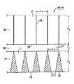
図16は、従来のルーバーシート20の一例を示す図である。
従来のルーバーシート20は、透明なシート状の光透過部21と、光透過部21の内部であってこのシート20の入光面(又は出光面)の法線方向に、所定の間隔で形成された光吸収部22とを備えていた。
【0004】
このルーバーシート20は、光線Rが入光すると、入光面23で屈折して、光透過部21の中を進行し、出光面24で再び屈折して、出光していく。図16には、光吸収部22の付近に入光した場合が示してあるが、他の部分に入光した場合も同様である。
【0005】
図16の場合に、光線Rは、光吸収部22(n)の近くに入光し、光透過部21の中を進行し、次の光吸収部22(n+1)の付近から出光している。
このとき、光吸収部22の端部Aと端部Bを結ぶ直線は、ルーバーシート20の法線方向とαの角度をなし、光線Rの進行方向も同じである。入光面23で屈折し、αの角度に進む光線Rは、ルーバーシート20に対して、βの角度で入光した光である。
【0006】
この角度αとβの関係は、ルーバーシート20の光透過部21の屈折率をnとすると次式で表される。
n×sinα=sinβ ・・・(1)
ここで、nは1よりも大きいので、β>αとなる。また、出光面24でも同じ関係が成り立つので、出光角度も入光角度と同じβとなる。
【0007】
この角度αとβの関係は、0°からβの角度に入光した光線Rは、0°からαの角度に進んでいく。この光線Rは、出光面24から0°からβの角度に出光する。しかし、入光角度がβから90°の光は、αから90°の角度に進んでいき、光吸収部22で吸収されてしまう。
したがって、ルーバーシート20は、進行できる光線Rが0°からβの角度になる。この理由は、0°からβの角度に入光した光線Rのみが光透過部21を通過でき、他の光線Rは、光吸収部22で吸収されてしまうためである。つまり、ルーバーシート20は、入光する光線Rのすべて(すなわち−90°から+90°の入光角の光)のうち、β/180°の割合の光線のみを通過するように、光線方向を制御することができる。
【0008】
通過できる光線Rの角度は、入光する点Aによって異なるが、通過できる光線Rの割合は、ほぼ同じである。例えば、光吸収部22(n)と光吸収部22(n+1)の中間の位置に、入光する光線Rでは、約±(1/2)αに進行する光線Rが通過する。したがって、約±(1/2)βの範囲に入光する光線Rが通過するので、通過する光線Rの割合は、約β/180である。
【0009】
【発明が解決しようとする課題】
このように、上述した従来のルーバーシート20は、どの点Aに入光する光線Rも、約β/180の光が通過するので、全体として通過する光の割合は、約β/180である。
したがって、出光する光の出光角度の範囲を狭めようとすると、有効に利用できる光の割合も減少するが、例えば、βを30°とすると、30°/180°=1/6となり、利用できる光の割合は、1/6となってしまう。
【0010】
このように、従来の技術では、ルーバーシート20は、法線方向及びその付近の方向に進む光以外の光、つまり、制御しようとする方向に進まない光を吸収することにより、法線方向に近い方向に制御していたために、入光する光のうち数分の1程度しか利用できず、入光する光の多くを損失してしまうという問題点があった。
【0011】
本発明の課題は、光の損失を抑えつつ、光の進行方向を制御することができる光線方向制御シート、視認性向上シート、光源装置及びディスプレイを提供することである。
【0012】
【課題を解決するための手段】
前記課題を解決するために、請求項1の発明は、光透過部と、前記光透過部の入光面から入光した光の一部を、その出光面から出光させるように反射させる反射部とを備え、前記反射部は、前記入光面での入光角度よりも、前記出光面の出光角度が小さくなるように反射させることを特徴とする光線方向制御シートである。
【0013】
請求項2の発明は、請求項1に記載された光線方向制御シートにおいて、前記反射部は、出光面からの光の出光角度が−40度〜+40度となるように反射することを特徴とする光線方向制御シートである。
【0014】
請求項3の発明は、請求項1又は請求項2に記載された光線方向制御シートにおいて、前記反射部は、その反射面が、前記入光面の法線に対して5〜15°の角度をなす斜面、又は、接線が5〜15°の角度をなす曲面であることを特徴とする光線方向制御シートである。
【0015】
請求項4の発明は、請求項1から請求項3までのいずれか1項に記載された光線方向制御シートにおいて、前記反射部は、その反射面が、屈折率の異なる界面であることを特徴とする光線方向制御シートである。
【0016】
請求項5の発明は、請求項1から請求項4までのいずれか1項に記載された光線方向制御シートにおいて、前記反射部は、入光側に遮光層を形成したことを特徴とする光線方向制御シートである。
【0017】
請求項6の発明は、請求項1から請求項5までのいずれか1項に記載された光線方向制御シートにおいて、前記反射部は、入光側の光が入光しない部分に、反射層を形成したことを特徴とする光線方向制御シートである。
【0018】
請求項7の発明は、請求項1から請求項6までのいずれか1項に記載の光線方向制御シートと、前記光線方向制御シートの出光側に、その入射面の法線方向に所定間隔で形成された光吸収層を備える出光側光線方向制御シートと、を備える視認性向上シートである。
【0019】
請求項8の発明は、請求項7に記載の視認性向上シートにおいて、前記出光側光線方向制御シートは、入光の位置が、前記光線方向制御シートの隣接する入光部の隣接する端部に、その端部からその入光部に向かう方向に入光する光のうち、最大の入光角を持つ光が出光したのち、交差する点の付近となるように配置したことを特徴とする視認性向上シートである。
【0020】
請求項9の発明は、請求項8に記載の視認性向上シートにおいて、前記光線方向制御シートと前記出光側光線方向制御シートとは、スペーサ又は接合層を介して接合されていることを特徴とする視認性向上シートである。
【0021】
請求項10の発明は、請求項1から請求項6までのいずれか1項に記載の光線方向制御シートと、前記光線方向制御シートの入光側に配置した光源と、を備えることを特徴とする光源装置である。
【0022】
請求項11の発明は、請求項7から請求項9までのいずれか1項に記載の視認性向上シートと、前記視認性向上シートの入光側に配置した光源と、を備えることを特徴とする光源装置である。
【0023】
請求項12の発明は、請求項10又は請求項11に記載の光源装置において、前記光源からの光を反射する光源側反射層を備えることを特徴とする光源装置である。
【0024】
請求項13の発明は、請求項10から請求項12までのいずれか1項に記載の光源装置において、前記光源は、前記光線方向制御シート又は前記視認性向上シートに含まれる前記光線方向制御シートの入光部に対応する位置に配置されていることを特徴とする光源装置である。
【0025】
請求項14の発明は、請求項10から請求項13までのいずれか1項に記載の光源装置において、前記光線方向制御シートと前記光源とは、その光線方向制御シートの光を入光しない部分と、前記光源の光を発光しない部分とによって接合されていることを特徴とする光源装置である。
【0026】
請求項15の発明は、請求項1から請求項6までのいずれか1項に記載の光源方向制御シート、請求項7から請求項9までのいずれか1項に記載の視認性向上シート、又は、請求項10から請求項14までのいずれか1項に記載の光源装置のいずれかを含むディスプレイである。
【0027】
【発明の実施の形態】
以下、図面などを参照しながら、本発明の実施の形態をあげて、さらに詳しく説明する。
(光線方向制御シートの第1実施形態)
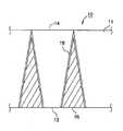
図1〜図3は、本発明による光線方向制御シートの第1実施形態を示す図である。
第1実施形態の光線方向制御シート10は、光透過部11と、光透過部11の入光面13から入光した光の一部を、その出光面14から出光させるように反射させる反射部15とを備えている。この反射部15は、入光面13での入光角度よりも、出光面14の出光角度が小さくなるように反射させるようにしたものである。
【0028】
この光線方向制御シート10は、入光側の一部が透明な入光面13であり、他の部分が光を透過しない遮光部16となっている。そして、この光線方向制御シート10は、その内部に設けられた反射部15によって、入光面13から入光した光の一部を出光側に反射する。この実施形態では、反射部15は、出光側に向かって開いていくように傾いた斜面となっている。
具体的には、反射部15は、出光面14からの光の出光角度が−40度〜+40度となるように反射することが好ましい。このとき、反射部15は、その反射面が、入光面の法線に対して5〜15°の角度をなしていることが望ましい。
【0029】
ここで、本実施形態の光線方向制御シート10は、光透過部11を構成する材質が、透明な樹脂であればよく、アクリル、ポリカーボネート、エポキシ、ウレタンアクリレート、ポリエステル等が好ましい用いられる。
【0030】
反射部15は、反射率の高い金属であればよく、例えば、アルミニウムであれば蒸着によって形成すればよく、銀であれば銀鏡反応を用いればよい。
【0031】
また、反射部15は、光透過部11より低屈折な樹脂を用いてもよい。これは、反射面に対して、光が50°程度以上の大きな入光角度で入光するので、光透過部11の樹脂と、反射部15の樹脂の屈折率の差がある程度大きく、臨界角を60°程度以上に大きくすれば、全反射により反射するからである。
例えば、光透過部11の屈折率が1.57の場合には、反射部15として、屈折率=1.34の樹脂を用いれば、臨界角=59.3°となり、この角度以上で入光する光は、全反射するので光線方向制御シート10では、すべて反射する。低屈折率樹脂としては、フッ素系樹脂等を用いることができる。
【0032】
また、遮光部16としては、カーボンブラック等を含む黒色インク等を用いることができる。
【0033】
図2は、第1実施形態による光線方向制御シートに入光した光線の光路を示す図である。
まず、光路a,bは、光線方向制御シート10の法線方向に近い角度、つまり、入光角が小さい角度で入光する光であって、光透過部11の中を進行して、出光面14から出光する。
【0034】
光路c,dは、光路bよりも入光角が大きくなる光であって、反射部15によって反射したのちに、出光面14から出光する。これらの場合には、まず、入光面13で屈折し、入光角よりも屈折角の方が小さくなる。また、反射部15は、出光面14の方に開くように傾いているので、反射部15に入射する光の法線方向に対する角度よりも、反射光の法線方向に対する角度の方が小さくなる。したがって、この光が出光面14で屈折して出光するときの出光角は、入光面13での入光角よりも小さくなる。
このように、本実施形態による光線方向制御シート10では、入光した光の拡がりよりも、出光する光の拡がりを狭くすることができる。
【0035】
図3は、第1実施形態による光線方向制御シートの具体的な形状を詳細に示した図である。
光線方向制御シート10は、入光側の入光面13の幅L1と、遮光部16の幅L2との比率を、L1:L2=1:1.88、入光面13の幅L1とシート10の厚みTとの比率を、L1:T=1:5.33、光透過部11の屈折率を1.57とすると、図3に示すように、入光面13の中心に入光する光において、光路bを通る光は、入光角が24.1°で、屈折角が15.1°となり、出光面14からの出光角が24.1°になる。
【0036】
これより大きな角度で入光する光は、光路c,dを通るが、もし、光路cとして、入光角を40°とすると、屈折角が24.2°で、出光面14への入光角が4.2°となり、出光面14からの出光角が6.6°である。
また、光路dとして、入光角を90°とすると、入光面13の屈折角は39.6°で、出光面14への入光角が19.6°となり、出光面14からの出光角が31.8°である。
【0037】
このように、本実施形態では、入光面13に入光した光は、−30°〜+30°の範囲に出光する。この実施形態の場合に、入光側の面積のうち、入光面13のしめる割合は、1/2.88=0.347であり、従来の技術で説明した30/180=1/6=0.166よりも0.347/0.166=2.09倍の光が利用できることになる。
【0038】
本実施形態では、反射部15がシート10の法線となす角は、10°であるがこの角度が小さくなり過ぎると、反射部15に入射する光と、反射部15で反射した光のシート10の法線とのなす角の差が少なくなり、つまり、反射しても光線のシート10の法線に対しての向きが変化しないので、光の向きを制御できなくなる。
また、この角度が大きくなると、反射部15に入射せずに、出光面14に入射する光の最大入光角(出光面13に対する)が大きくなり、また、そのような光の割合も大きくなるので、出光する光の出光角の範囲が広がってしまい、光の向きを制御できなくなる。
従って、出光する光の角度をシート10の法線方向からある範囲の角度にするには、反射部14のシート10の法線方向に対する角度は、5〜15°の範囲に実用的であり、10°程度がより好ましい。
【0039】
(光線方向制御シートの他の実施形態)
図4は、本発明による光線方向制御シートの第2実施形態を示す図である。
第2実施形態の光線方向制御シート10−2は、入光面13及び出光面14に、光透過部11が連続するようにしてある。
この形態にすると、シートの厚みを厚くでき、シートの強度も上げることができるのでシートの取り扱いが容易になり、また、シートの上に粘着層をコーティングするなどの加工も容易になる。
【0040】
図5は、本発明による光線方向制御シートの第3実施形態を示す図である。
第2実施形態の光線方向制御シート10−3は、反射部14の上に、遮光部16−3を薄く形成したものである。
この形態にすると、遮光層の機能があれば厚い必要はないので、谷部全体に遮光層を形成しなくてもよい。また、遮光層の材料を節約することができる。
【0041】
図6は、本発明による光線方向制御シートの第4実施形態を示す図である。
第4実施形態の光線方向制御シート10−4は、反射部15−4を金属等の遮光性がある材料で形成したものであり、上述した各実施形態のように、反射部15の上に遮光部16を形成する必要はない、という利点がある。
【0042】
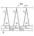
(光源装置の第1実施形態)
図7は、本発明による光線方向制御シートを用いた光源装置の第1実施形態を示す図である。
第1実施形態の光源装置30は、第4実施形態の光線方向制御シート10−4と、この光線方向制御シート10−4の入光側に配置された蛍光灯、EL(エレクトリック ルミネッセンス)等の光源31を備えたものであり、向きのそろった光を出光することが可能となる。
【0043】
このとき、光源31側にも反射層32を設けると、入光面13から入光する光が増え、さらに効率が良くなる。
この光源装置30は、光の向きがそろっているので、液晶表示装置の光源装置に用いると、液晶表示装置を透過する光の割合が高く、トータルの光の利用効率を上げることができるという利点がある。
【0044】
(光源装置の第2実施形態)
図8は、本発明による光線方向制御シートを用いた光源装置の第2実施形態を示す図である。
第2実施形態の光源装置30−2は、光源31の光を反射するためには、入光側の入光面13以外の部分を、反射層15Aとしたものであり、反射の効率が向上する利点がある。
【0045】
この理由は、図7に示したような谷状の反射部15−4であると、1度の反射では光源側に光が戻らないからである。反射といっても100%反射するわけではないので、反射を繰り返すと吸収される部分が増えるからである。
【0046】
(光源装置の第3実施形態)
図9は、本発明による光線方向制御シートを用いた光源装置の第3実施形態を示す図である。
第2実施形態の光源装置30−3では、光源33として、ELを用いたものである。ELは、発光する部分を小さな面積で多数形成することができるので、入光面13に対応する部分に発光部33aを配置すれば、さらに効率を上げることができる。このとき、発光しない部分に、反射層34を形成すると、さらに光の有効利用ができて好ましい。
【0047】
(光源装置の第4実施形態)
図10は、本発明による光線方向制御シートを用いた光源装置の第4実施形態を示す図である。
第4実施形態の光源装置30−4は、光線方向制御シート10−4と、光源33の発光部33aとの距離をできるだけ近づけるようにしたものである。このようにするには、図10に示すように、光線方向制御シート10−4と光源33とを、スペーサ35を介して接合すればよい。
この光源装置30−4では、空気層がある場合よりも効率は低下するが、低屈折な材料からなる光透過部11を介して接合すればよい。つまり、この場合には、発光部33aと光透過部11の間は空気層になる。これに対して、この空気層の部分及びスペーサ35の部分を低屈折で透明な層としてもよいが、空気層の場合よりも効率は低下することになる。
【0048】
(視認性向上シートの第1実施形態)
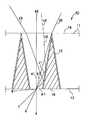
図11は、本発明による視認性向上シートの第1実施形態を示す図、図12は、本発明の実施形態による光線方向制御シートの入光面の端部に入光した光の光路を示す図である。
【0049】
まず、上述した光線方向制御シート10における光の光路を、さらに詳しく説明する。図2では、入光面13の中心部に入光した光の光路(a〜d)について説明したが、図12では、入光面13の端部に入光した光の光路(e〜h)について説明する。
【0050】
光路eは、入光面13の入光角=32.5°、屈折角=20°であり、出光面14への入光角=20.0°、出光面14からの出光角32.5°である。
光路fは、入光面13の入光角=40°、屈折角=24.2°であり、出光面14への入光角=4.2°、出光面14からの出光角=6.6°である。
光路gは、入光面13の入光角=60°、屈折角=33.5°であり、出光面14への入光角=13.5°、出光面14からの出光角=21.5°である。
光路hは、入光面13の入光角=90°、屈折角=39.6°であり、出光面14への入光角=19.6°、出光面14からの出光角=31.8°である。
【0051】
この図12と図2をあわせて考えると、出光面14の位置により、出光角の分布は異なり、反射部15の中間部では、±20°の範囲に、反射部15に近い部分では、0°〜30°の範囲に出光する光が多いことがわかる。
そこで、第1実施形態の視認性向上シート40は、光線方向制御シート10の出光側に、従来の技術(図16参照)で説明した光線方向制御シート20を配置したものである。
【0052】
図11に示すように、光線方向制御シート10の反射部15の位置と、光線方向制御シート20の光吸収部22の位置を合わせ、しかも、反射層15の左右の出光面13から出光する光のうち、図12のh3の光が交差する付近に、光線方向制御シート20の入光面23を配置することにより、光線方向制御シート10から出光する光のほとんどが、光線方向制御シート20を通過するようにすることができる。
【0053】
この理由は、光線方向制御シート20は、前述したように、光吸収部22に近い部分では、0〜30°の光を、中心部では±15°の光を通過させることができ、上述した配置にすれば、光線方向制御シート10から出光した光を、上述したように、光線方向制御シート20に入光させることができるからである。
【0054】
このように、本実施形態によれば、光線方向制御シート20は、光吸収部22があるので、入光面23からはってくる光(外光)を、光吸収部22で吸収することができる。このため、光線方向の制御以外に、画像の外光下でのコントラストを向上させる視認性向上シート40として用いることができる。
つまり、視認性向上シート40は、上記構成のものを、上記用途に用いることにより、画像光の利用率が高くすると共に、視認性を向上させることができるという利点がある。
【0055】
視認性向上シート40は、光線方向制御シート10において、その反射部15が金属のようにどの方向からきた光も反射してしまうものよりも、屈折率の異なる界面とし、その裏に遮光部15があるような構造、又は、低屈折率層の中に光を吸収する粒子があるような構造が好ましい。
この理由は、上記のようにすれば、臨界角以上の特定の光は反射するが、それ以外の光は吸収するので、画像光は反射し、外光は吸収することができ、遮光部15もコントラストの向上に寄与することができるからである。
【0056】
ここで、光線方向制御シート10と光線方向制御シート20とを組合わせる場合には、前述したように、その間に間隔を取った方がよいが、その方法は次のようなものが好ましい。
例えば、第1実施形態の視認性向上シート40は、光線方向制御シート10と光線方向制御シート20との間に、空気層41を介して配置したものである。シート10,20の剛性が十分であれば、前述したような間隔をおいて、シート10,20を配置すればよいが、不十分な場合には、スペーサ(粒子等)を介して配置することが望ましい。
【0057】
(視認性向上シートの第2実施形態)
図13は、本発明による視認性向上シートの第2実施形態を示す図である。
第2実施形態の視認性向上シート40−2は、光線方向制御シート10と光線方向制御シート20との間に光透過シート42を介して接合したものである。
【0058】
光透過シート42の厚みは、前述したような間隔とする。ただし、空気層41とは、屈折率が異なるので、光路hの光の光線方向制御シート10の出光面14からの光路は、図12に示したものと少し異なるので、最適な間隔も異なる。
図13は、光線方向制御シート10の光透過部11の屈折率と、光線方向制御シート20の光透過部21の屈折率と、光透過シート42の屈折率を同じにした場合を示したものである。
【0059】
(変形形態)
以上説明した実施形態に限定されることなく、種々の変形や変更が可能であって、それらも本発明の均等の範囲内である。
(1)上記実施形態の光線方向制御シートは、反射部15が上述したような直線でなく、角度の異なる2つ以上の直線を接続した折線もしくは曲線(例えば、接線が5〜15°の角度をなす曲面)であってもよい。
このとき、反射部15に対して小さい入光角で入ってくる光は、反射部15の入光面12に近い部分の方が多いので、入光側に近い部分のシートの法線に対する角度を大きくするほうが、出射光の出光角の広がる範囲を狭められるので好ましい。
【0060】
(2)上記実施形態の光線方向制御シートは、図示した断面形状が断面を含む平面に垂直な方向に連続していく形状、すなわち1次元構造であったが、図示した形状が縦方向と横方向に連続していく、すなわち反射部15が四角錐台の側面であり、それが多数平面上に形成された2次元構造でもよい。
また、反射部15が円錐台の側面で、それが多数平面上に形成された2次元構造であってもよい。
【0061】
(3)図1,図4,図5,図11,図13,図14,図15のシートの場合にも、図7〜図10のような光源と組み合わせることによって、光源装置を作製することができ、また、それを用いたディスプレイを作製することもできる。
【0062】
【実施例】
以下、具体的な実施例をあげて本発明を詳細に説明する。
(実施例1)
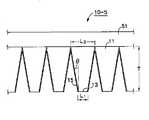
図14は、本発明による光線方向制御シートの実施例を示す図である。
この光線方向制御シート10−5は、ベースフィルム(PETフィルム、厚み100μm、屈折率1.58)51の上に、光透過部11を、この台形状(入光側の幅L1=50μm、出光側の幅L3=144μm、斜面の角度θ=10°)の逆形状の金型(ロール状)を用いて、このロールとベースフィルム51の間に、UV硬化樹脂を充填しながら、圧着させたのちに、UV光を照射してUV硬化樹脂を硬化させることにより形成した(硬化後の屈折率=1.57)。
【0063】
次に、入光側の台形の頂上部分(50μm幅)に、ポリビニールアルコール樹脂を、10μm程度コーティングしたのち、アルミニウムを1μm蒸着した。その後に、ポリビニールアルコール層を水に溶解して除去して、反射層15を形成した。
こうして作製した光線方向制御シート10−5に、入光側に光源として蛍光灯を配置して光を照射したところ、−30°〜+30°の範囲に発光する光源装置が得られた。
【0064】
(実施例2)
図15は、本発明による視認性向上シートの実施例を示す図である。
この視認性向上シート40−3は、ベースフィルム(PETフィルム、厚み120μm、屈折率1.58)52の片面に、実施例1と同様の形状を、同様の方法で形成した。
【0065】
次に、硬化後の屈折率が1.34になるようなUV硬化樹脂の中に、平均粒径5μmの黒色ビーズを混ぜたものを、谷部に充填し硬化させ、遮光部16を形成した。
さらに、シート52の反対面に対して、幅L4=5μmで、深さT3=370μmの溝を有する形状を、その形状の逆形状を用いて、溝の位置と初めに形成した形状の谷部の位置があうようにして形成した。
最後に、この溝に黒色インキを充填し硬化させて、光吸収部22を形成した。このようにし、視認性向上シート40−3を作製した。
この視認性向上シート40−3を、液晶ディスプレイの表面に配置したところ、屋外光の下でもコントラストの高い画像が視認できた。
【0066】
【発明の効果】
以上説明したように、本発明によれば、入光した光のうち、制御しようとする方向(シートの法線方向)に進まない光を吸収するのではなく、それ以外の方向に進む光を、反射させて制御しようとする方向に進ませることにより、光の損失を抑えながら、光の進む方向をそろえる制御を行うことができる。
【図面の簡単な説明】
【図1】本発明による光線方向制御シートの第1実施形態を示す図である。
【図2】第1実施形態による光線方向制御シートに入光した光線の光路を示した図である。
【図3】第1実施形態による光線方向制御シートの具体的な形状を詳細に示した図である。
【図4】本発明による光線方向制御シートの第2実施形態を示す図である。
【図5】本発明による光線方向制御シートの第3実施形態を示す図である。
【図6】本発明による光線方向制御シートの第4実施形態を示す図である。
【図7】本発明による光線方向制御シートを用いた光源装置の第1実施形態を示す図である。
【図8】本発明による光線方向制御シートを用いた光源装置の第2実施形態を示す図である。
【図9】本発明による光線方向制御シートを用いた光源装置の第3実施形態を示す図である。
【図10】本発明による光線方向制御シートを用いた光源装置の第4実施形態を示す図である。
【図11】本発明による視認性向上シートの第1実施形態を示す図である。
【図12】本発明の実施形態による光線方向制御シートの入光面の端部に入光した光の光路を示す図である。
【図13】本発明による視認性向上シートの第2実施形態を示す図である。
【図14】本発明による光線方向制御シートの実施例を示す図である。
【図15】本発明による視認性向上シートの実施例を示す図である。
【図16】従来の光線方向制御シート(ルーバーシート)の一例を示す図である。
【符号の説明】
10 光線方向制御シート
11 光透過部
13 入光面
14 出光面
15 反射部
16 遮光部
20 光線方向制御シート
21 光透過部
22 光吸収部
23 入光面
24 出光面
30 光源装置
40 視認性向上シート[0001]
TECHNICAL FIELD OF THE INVENTION
The present invention relates to a light direction control sheet for aligning the direction of light from a light source, a visibility improving sheet, a light source device, and a display.
[0002]
[Prior art]
Conventionally, as this kind of light direction control sheet, a slit having a light absorbing portion and a light transmitting portion formed in a stripe shape on the sheet, and a louver having a light absorbing portion formed perpendicularly to the sheet inside the sheet have been used. Was.
[0003]
FIG. 16 is a diagram illustrating an example of a
The
[0004]
When the light ray R enters the
[0005]
In the case of FIG. 16, the light ray R enters near the light absorbing section 22 (n), travels through the
At this time, the straight line connecting the end A and the end B of the
[0006]
The relationship between the angles α and β is expressed by the following equation, where n is the refractive index of the
n × sin α = sin β (1)
Here, since n is larger than 1, β> α. In addition, since the same relationship holds for the
[0007]
The relationship between the angles α and β is such that the light ray R incident from an angle of 0 ° to β advances from 0 ° to an angle of α. The light ray R is emitted from the
Therefore, in the
[0008]
Although the angle of the light beam R that can pass varies depending on the incident point A, the ratio of the light beam R that can pass is almost the same. For example, the light ray R entering the intermediate position between the light absorbing part 22 (n) and the light absorbing part 22 (n + 1) passes through the light ray R traveling about ± (1/2) α. Therefore, since the light ray R entering the range of about ± (1/2) β passes, the ratio of the passing light ray R is about β / 180.
[0009]
[Problems to be solved by the invention]
As described above, in the
Therefore, if the range of the light emission angle of the emitted light is reduced, the ratio of the light that can be effectively used also decreases. For example, when β is 30 °, 30 ° / 180 ° = 1/6, which is usable. The ratio of light becomes 1/6.
[0010]
As described above, in the related art, the
[0011]
An object of the present invention is to provide a light beam direction control sheet, a visibility improving sheet, a light source device, and a display capable of controlling the traveling direction of light while suppressing loss of light.
[0012]
[Means for Solving the Problems]
In order to solve the above-mentioned problem, the invention according to
[0013]
According to a second aspect of the present invention, in the light beam direction control sheet according to the first aspect, the reflecting portion reflects the light so that the light exit angle of the light from the light exit surface is −40 degrees to +40 degrees. FIG.
[0014]
According to a third aspect of the present invention, in the light beam direction control sheet according to the first or second aspect, the reflecting portion has an angle of 5 to 15 ° with respect to a normal to the light incident surface. Or a curved surface whose tangent forms an angle of 5 to 15 °.
[0015]
According to a fourth aspect of the present invention, in the light beam direction control sheet according to any one of the first to third aspects, the reflection portion of the reflection portion is an interface having a different refractive index. Is a light direction control sheet.
[0016]
According to a fifth aspect of the present invention, in the light beam direction control sheet according to any one of the first to fourth aspects, the light-reflecting portion has a light-shielding layer formed on a light incident side. It is a direction control sheet.
[0017]
According to a sixth aspect of the present invention, in the light beam direction control sheet according to any one of the first to fifth aspects, the reflection portion includes a reflection layer on a portion where light on the light incident side does not enter. It is a light direction control sheet characterized by being formed.
[0018]
According to a seventh aspect of the present invention, there is provided a light direction control sheet according to any one of the first to sixth aspects, and a light emitting side of the light direction controlling sheet at a predetermined interval in a normal direction of an incident surface thereof. And a light exit side light direction control sheet including the formed light absorbing layer.
[0019]
According to an eighth aspect of the present invention, in the visibility enhancing sheet according to the seventh aspect, the light exit side light direction control sheet has a light incident position adjacent to an end of an adjacent light entrance portion of the light direction control sheet. In addition, of the light incident from the end portion in the direction toward the light incident portion, after the light having the maximum incident angle is emitted, the light is arranged so as to be near the intersection. It is a visibility improving sheet.
[0020]
According to a ninth aspect of the present invention, in the visibility enhancing sheet according to the eighth aspect, the light beam direction control sheet and the light exit side light direction control sheet are bonded via a spacer or a bonding layer. This is a visibility improving sheet.
[0021]
According to a tenth aspect of the present invention, there is provided a light direction control sheet according to any one of the first to sixth aspects, and a light source disposed on a light incident side of the light direction control sheet. Light source device.
[0022]
According to an eleventh aspect of the present invention, there is provided the visibility improving sheet according to any one of the seventh to ninth aspects, and a light source disposed on a light incident side of the visibility enhancing sheet. Light source device.
[0023]
According to a twelfth aspect of the present invention, in the light source device according to the tenth or eleventh aspect, the light source device further comprises a light source side reflection layer that reflects light from the light source.
[0024]
According to a thirteenth aspect of the present invention, in the light source device according to any one of the tenth to twelfth aspects, the light source is included in the light direction control sheet or the visibility improving sheet. A light source device, wherein the light source device is disposed at a position corresponding to a light incident portion.
[0025]
According to a fourteenth aspect of the present invention, in the light source device according to any one of the tenth to thirteenth aspects, the light beam direction control sheet and the light source are portions of the light direction control sheet that do not receive light. And a portion that does not emit light from the light source.
[0026]
According to a fifteenth aspect of the present invention, there is provided a light source direction control sheet according to any one of the first to sixth aspects, a visibility improving sheet according to any one of the seventh to ninth aspects, or A display comprising any one of the light source devices according to any one of
[0027]
BEST MODE FOR CARRYING OUT THE INVENTION
Hereinafter, embodiments of the present invention will be described in more detail with reference to the drawings and the like.
(First Embodiment of Light Direction Control Sheet)
1 to 3 are views showing a first embodiment of a light beam direction control sheet according to the present invention.
The light beam
[0028]
In the light beam
Specifically, it is preferable that the
[0029]
Here, in the light beam
[0030]
The reflecting
[0031]
In addition, the
For example, when the refractive index of the
[0032]
Further, as the
[0033]
FIG. 2 is a diagram illustrating an optical path of a light beam incident on the light beam direction control sheet according to the first embodiment.
First, the light paths a and b are light that enters at an angle close to the normal direction of the light beam
[0034]
The light paths c and d are lights having a larger light incident angle than the light path b. The light paths c and d are emitted from the
As described above, in the light beam
[0035]
FIG. 3 is a diagram showing in detail a specific shape of the light beam direction control sheet according to the first embodiment.
The light beam
[0036]
Light entering at an angle larger than this passes through the optical paths c and d. If the incident angle of light is 40 ° as the optical path c, the refraction angle is 24.2 ° and the light entering the
Assuming that the light incident angle is 90 ° as the optical path d, the refraction angle of the
[0037]
As described above, in the present embodiment, light that has entered the
[0038]
In the present embodiment, the angle formed by the
When this angle increases, the maximum light incident angle (with respect to the light exit surface 13) of the light incident on the
Therefore, in order to set the angle of the emitted light to be within a certain range from the normal direction of the
[0039]
(Other Embodiments of Light Direction Control Sheet)
FIG. 4 is a view showing a second embodiment of the light beam direction control sheet according to the present invention.
In the light beam direction control sheet 10-2 of the second embodiment, the
In this form, the thickness of the sheet can be increased, and the strength of the sheet can be increased, so that the handling of the sheet is facilitated, and processing such as coating an adhesive layer on the sheet is also facilitated.
[0040]
FIG. 5 is a view showing a third embodiment of the light beam direction control sheet according to the present invention.
The light beam direction control sheet 10-3 of the second embodiment has a light shielding portion 16-3 formed thinly on the
In this embodiment, the light shielding layer does not need to be thick as long as it has the function of the light shielding layer. Further, the material of the light shielding layer can be saved.
[0041]
FIG. 6 is a view showing a fourth embodiment of the light beam direction control sheet according to the present invention.
In the light beam direction control sheet 10-4 of the fourth embodiment, the reflecting portion 15-4 is formed of a material having a light-shielding property such as a metal, and is provided on the reflecting
[0042]
(First Embodiment of Light Source Device)
FIG. 7 is a view showing a first embodiment of a light source device using the light beam direction control sheet according to the present invention.
The
[0043]
At this time, if the
Since the
[0044]
(Second embodiment of light source device)
FIG. 8 is a view showing a second embodiment of the light source device using the light beam direction control sheet according to the present invention.
In the light source device 30-2 of the second embodiment, in order to reflect the light of the
[0045]
The reason is that, in the case of the valley-shaped reflecting portion 15-4 as shown in FIG. 7, the light does not return to the light source side by one reflection. This is because the reflection does not mean 100% reflection, and therefore, if the reflection is repeated, the absorbed portion increases.
[0046]
(Third Embodiment of Light Source Device)
FIG. 9 is a view showing a third embodiment of the light source device using the light beam direction control sheet according to the present invention.
In the light source device 30-3 of the second embodiment, EL is used as the
[0047]
(Fourth Embodiment of Light Source Device)
FIG. 10 is a view showing a fourth embodiment of the light source device using the light beam direction control sheet according to the present invention.
In the light source device 30-4 of the fourth embodiment, the distance between the light beam direction control sheet 10-4 and the
In the light source device 30-4, although the efficiency is lower than in the case where there is an air layer, the light source device 30-4 may be joined via the
[0048]
(First Embodiment of Visibility Improvement Sheet)
FIG. 11 is a diagram illustrating a first embodiment of a visibility improving sheet according to the present invention, and FIG. 12 is a diagram illustrating an optical path of light incident on an end of a light incident surface of the light beam direction control sheet according to the embodiment of the present invention. FIG.
[0049]
First, the optical path of light in the above-described light beam
[0050]
The optical path e has a light incident angle of the
In the optical path f, the light incident angle of the
The optical path g is such that the light incident angle of the
The light path h has a light incident angle of the
[0051]
When FIG. 12 and FIG. 2 are considered together, the distribution of the light output angle differs depending on the position of the
Therefore, the
[0052]
As shown in FIG. 11, the position of the
[0053]
The reason for this is that, as described above, the light
[0054]
As described above, according to the present embodiment, since the light
In other words, the
[0055]
The
The reason for this is that, as described above, specific light having a critical angle or more is reflected, but other light is absorbed, so that image light can be reflected and external light can be absorbed. This can also contribute to an improvement in contrast.
[0056]
Here, when the light
For example, the
[0057]
(2nd Embodiment of visibility improvement sheet)
FIG. 13 is a view showing a second embodiment of the visibility improving sheet according to the present invention.
The visibility improving sheet 40-2 of the second embodiment is formed by bonding the light
[0058]
The thickness of the
FIG. 13 shows a case where the refractive index of the
[0059]
(Modified form)
Various modifications and changes are possible without being limited to the embodiment described above, and these are also within the equivalent scope of the present invention.
(1) In the light beam direction control sheet of the above-described embodiment, the reflecting
At this time, since the light that enters the
[0060]
(2) The light beam direction control sheet of the above embodiment has a shape in which the illustrated cross-sectional shape is continuous in a direction perpendicular to a plane including the cross-section, that is, a one-dimensional structure. The reflecting
Further, the reflecting
[0061]
(3) In the case of the sheets shown in FIGS. 1, 4, 5, 11, 13, 13, and 15, a light source device is manufactured by combining with the light source shown in FIGS. And a display using the same can be manufactured.
[0062]
【Example】
Hereinafter, the present invention will be described in detail with reference to specific examples.
(Example 1)
FIG. 14 is a view showing an embodiment of a light beam direction control sheet according to the present invention.
The light beam direction control sheet 10-5 includes a base film (PET film, thickness: 100 μm, refractive index: 1.58), and a
[0063]
Next, a 10 μm-thick polyvinyl alcohol resin was coated on the top (50 μm width) of the trapezoid on the light incident side, and aluminum was deposited by 1 μm. Thereafter, the polyvinyl alcohol layer was dissolved in water and removed to form a
When a fluorescent lamp was arranged as a light source on the light incident side and light was applied to the light direction control sheet 10-5 thus produced, a light source device emitting light in the range of −30 ° to + 30 ° was obtained.
[0064]
(Example 2)
FIG. 15 is a view showing an embodiment of the visibility improving sheet according to the present invention.
This visibility improving sheet 40-3 was formed on one surface of a base film (PET film, thickness 120 μm, refractive index 1.58) 52 in the same manner as in Example 1 by the same method.
[0065]
Next, a mixture of black beads having an average particle size of 5 μm in a UV curable resin having a refractive index of 1.34 after curing was filled in the valleys and cured to form the light-shielding
Further, with respect to the opposite surface of the
Finally, the grooves were filled with black ink and cured to form the
When the visibility improving sheet 40-3 was disposed on the surface of the liquid crystal display, an image having high contrast could be visually recognized even under outdoor light.
[0066]
【The invention's effect】
As described above, according to the present invention, of the light that has entered, instead of absorbing light that does not travel in the direction to be controlled (the normal direction of the sheet), light that travels in other directions is absorbed. By causing the light to travel in the direction to be controlled by reflection, it is possible to control the light to travel in the same direction while suppressing light loss.
[Brief description of the drawings]
FIG. 1 is a view showing a first embodiment of a light beam direction control sheet according to the present invention.
FIG. 2 is a diagram illustrating an optical path of a light beam incident on a light beam direction control sheet according to the first embodiment.
FIG. 3 is a view showing in detail a specific shape of a light beam direction control sheet according to the first embodiment.
FIG. 4 is a view showing a second embodiment of the light beam direction control sheet according to the present invention.
FIG. 5 is a view showing a third embodiment of a light beam direction control sheet according to the present invention.
FIG. 6 is a view showing a fourth embodiment of a light beam direction control sheet according to the present invention.
FIG. 7 is a view showing a first embodiment of a light source device using a light beam direction control sheet according to the present invention.
FIG. 8 is a view showing a second embodiment of the light source device using the light beam direction control sheet according to the present invention.
FIG. 9 is a view showing a third embodiment of the light source device using the light beam direction control sheet according to the present invention.
FIG. 10 is a view showing a fourth embodiment of the light source device using the light beam direction control sheet according to the present invention.
FIG. 11 is a view showing a first embodiment of a visibility improving sheet according to the present invention.
FIG. 12 is a diagram illustrating an optical path of light incident on an end of a light incident surface of the light beam direction control sheet according to the embodiment of the present invention.
FIG. 13 is a view showing a second embodiment of the visibility improving sheet according to the present invention.
FIG. 14 is a view showing an embodiment of a light beam direction control sheet according to the present invention.
FIG. 15 is a view showing an embodiment of a visibility improving sheet according to the present invention.
FIG. 16 is a diagram illustrating an example of a conventional light direction control sheet (louver sheet).
[Explanation of symbols]
10 Beam direction control sheet
11 Light transmission part
13 Light incident surface
14 Light emitting surface
15 Reflector
16 Shading part
20 Beam direction control sheet
21 Light transmission part
22 Light absorbing part
23 Light incident surface
24 Light emitting surface
30 Light source device
40 Visibility improvement sheet
Claims (15)
Translated fromJapanese前記光透過部の入光面から入光した光の一部を、その出光面から出光させるように反射させる反射部とを備え、
前記反射部は、前記入光面での入光角度よりも、前記出光面の出光角度が小さくなるように反射させること
を特徴とする光線方向制御シート。A light transmitting portion;
A reflector that reflects part of the light incident from the light incident surface of the light transmitting portion so as to emit light from the light exit surface,
The light beam direction control sheet according to claim 1, wherein the reflection unit reflects the light so that the light exit angle of the light exit surface is smaller than the light entrance angle of the light entrance surface.
前記反射部は、出光面からの光の出光角度が−40度〜+40度となるように反射すること
を特徴とする光線方向制御シート。The light beam direction control sheet according to claim 1,
The light beam direction control sheet according to claim 1, wherein the reflection unit reflects the light so that the light exit angle of the light from the light exit surface is −40 degrees to +40 degrees.
前記反射部は、その反射面が、前記入光面の法線に対して5〜15°の角度をなす斜面、又は、接線が5〜15°の角度をなす曲面であること
を特徴とする光線方向制御シート。In the light beam direction control sheet according to claim 1 or claim 2,
The reflecting portion is characterized in that the reflecting surface is a slope having an angle of 5 to 15 ° with respect to a normal to the light incident surface, or a tangent is a curved surface having an angle of 5 to 15 °. Beam direction control sheet.
前記反射部は、その反射面が、屈折率の異なる界面であること
を特徴とする光線方向制御シート。In the light beam direction control sheet according to any one of claims 1 to 3,
The light-direction control sheet, wherein the reflection surface of the reflection section is an interface having a different refractive index.
前記反射部は、入光側に遮光層を形成したこと
を特徴とする光線方向制御シート。In the light beam direction control sheet according to any one of claims 1 to 4,
The light beam direction control sheet, wherein the reflection part has a light shielding layer formed on a light incident side.
前記反射部は、入光側の光が入光しない部分に、反射層を形成したこと
を特徴とする光線方向制御シート。In the light beam direction control sheet according to any one of claims 1 to 5,
The light beam direction control sheet, wherein the reflection portion has a reflection layer formed in a portion where light on the light incident side does not enter.
前記光線方向制御シートの出光側に、その入射面の法線方向に所定間隔で形成された光吸収層を備える出光側光線方向制御シートと、
を備える視認性向上シート。A light beam direction control sheet according to any one of claims 1 to 6,
On the light exit side of the light direction control sheet, a light exit side light direction control sheet comprising a light absorbing layer formed at a predetermined interval in a normal direction of the incident surface,
The visibility improvement sheet provided with.
前記出光側光線方向制御シートは、入光の位置が、前記光線方向制御シートの隣接する入光部の隣接する端部に、その端部からその入光部に向かう方向に入光する光のうち、最大の入光角を持つ光が出光したのち、交差する点の付近となるように配置したこと
を特徴とする視認性向上シート。The visibility improving sheet according to claim 7,
The light exit side light direction control sheet has a light incident position at an adjacent end of an adjacent light incident portion of the light direction control sheet, and a light incident in a direction from the end toward the light incident portion. A sheet for improving visibility, wherein the light having the largest light incidence angle is emitted and then arranged near an intersection.
前記光線方向制御シートと前記出光側光線方向制御シートとは、スペーサ又は接合層を介して接合されていること
を特徴とする視認性向上シート。The visibility improving sheet according to claim 8,
The visibility improving sheet, wherein the light beam direction control sheet and the light emission side light direction control sheet are bonded via a spacer or a bonding layer.
前記光線方向制御シートの入光側に配置した光源と、
を備えることを特徴とする光源装置。A light beam direction control sheet according to any one of claims 1 to 6,
A light source arranged on the light incident side of the light beam direction control sheet,
A light source device comprising:
前記視認性向上シートの入光側に配置した光源と、
を備えることを特徴とする光源装置。A visibility improving sheet according to any one of claims 7 to 9,
A light source arranged on the light incident side of the visibility improving sheet,
A light source device comprising:
前記光源からの光を反射する光源側反射層を備えること
を特徴とする光源装置。In the light source device according to claim 10 or 11,
A light source device comprising a light source side reflection layer that reflects light from the light source.
前記光源は、前記光線方向制御シート又は前記視認性向上シートに含まれる前記光線方向制御シートの入光部に対応する位置に配置されていること
を特徴とする光源装置。In the light source device according to any one of claims 10 to 12,
The light source device according to claim 1, wherein the light source is disposed at a position corresponding to a light incident portion of the light direction control sheet included in the light direction control sheet or the visibility improving sheet.
前記光線方向制御シートと前記光源とは、その光線方向制御シートの光を入光しない部分と、前記光源の光を発光しない部分とによって接合されていること
を特徴とする光源装置。In the light source device according to any one of claims 10 to 13,
The light source device, wherein the light beam direction control sheet and the light source are joined by a portion of the light beam direction control sheet that does not enter light and a portion of the light source that does not emit light.
Priority Applications (1)
| Application Number | Priority Date | Filing Date | Title |
|---|---|---|---|
| JP2002167534AJP4170677B2 (en) | 2002-06-07 | 2002-06-07 | Light source device and display |
Applications Claiming Priority (1)
| Application Number | Priority Date | Filing Date | Title |
|---|---|---|---|
| JP2002167534AJP4170677B2 (en) | 2002-06-07 | 2002-06-07 | Light source device and display |
Related Child Applications (2)
| Application Number | Title | Priority Date | Filing Date |
|---|---|---|---|
| JP2007255205ADivisionJP4171055B2 (en) | 2007-09-28 | 2007-09-28 | Display device |
| JP2007255176ADivisionJP2008052290A (en) | 2007-09-28 | 2007-09-28 | Optical sheet, display device |
Publications (3)
| Publication Number | Publication Date |
|---|---|
| JP2004012918Atrue JP2004012918A (en) | 2004-01-15 |
| JP2004012918A5 JP2004012918A5 (en) | 2007-11-22 |
| JP4170677B2 JP4170677B2 (en) | 2008-10-22 |
Family
ID=30434748
Family Applications (1)
| Application Number | Title | Priority Date | Filing Date |
|---|---|---|---|
| JP2002167534AExpired - Fee RelatedJP4170677B2 (en) | 2002-06-07 | 2002-06-07 | Light source device and display |
Country Status (1)
| Country | Link |
|---|---|
| JP (1) | JP4170677B2 (en) |
Cited By (51)
| Publication number | Priority date | Publication date | Assignee | Title |
|---|---|---|---|---|
| WO2005116698A1 (en)* | 2004-05-25 | 2005-12-08 | Dai Nippon Printing Co., Ltd. | Viewing-angle control sheet |
| JP2006171701A (en)* | 2004-11-18 | 2006-06-29 | Dainippon Printing Co Ltd | Viewing angle control sheet and liquid crystal display device using the same |
| JP2006171700A (en)* | 2004-11-18 | 2006-06-29 | Dainippon Printing Co Ltd | Viewing angle control sheet and liquid crystal display device using the same |
| KR100709985B1 (en)* | 2005-01-04 | 2007-04-23 | 삼성코닝 주식회사 | Filter for display device and display device including same |
| JP2007249052A (en)* | 2006-03-17 | 2007-09-27 | Nec Corp | Light control film, illuminator, and display device |
| KR100777736B1 (en)* | 2006-03-28 | 2007-11-19 | 삼성에스디아이 주식회사 | Ceff filter and plasma display device having same |
| KR100812345B1 (en)* | 2006-03-08 | 2008-03-11 | 삼성코닝정밀유리 주식회사 | Display filter and display device including same |
| KR100817560B1 (en)* | 2006-07-19 | 2008-03-27 | 엘지전자 주식회사 | Plasma display device |
| JP2008514989A (en)* | 2004-09-27 | 2008-05-08 | アイディーシー、エルエルシー | Optical film for controlling the angular characteristics of a display |
| JP2009524080A (en)* | 2006-01-12 | 2009-06-25 | スリーエム イノベイティブ プロパティズ カンパニー | Light collimating film |
| JP2009258754A (en)* | 2009-07-30 | 2009-11-05 | Dainippon Printing Co Ltd | Light converging sheet, surface light source apparatus and manufacturing method of light converging sheet |
| JP2009288799A (en)* | 2009-08-31 | 2009-12-10 | Dainippon Printing Co Ltd | Display device |
| JP2009294680A (en)* | 2009-09-24 | 2009-12-17 | Dainippon Printing Co Ltd | Contrast improvement sheet |
| JP2010096882A (en)* | 2008-10-15 | 2010-04-30 | Sony Corp | Reflection plate, light-emitting device and method for manufacturing reflection plate |
| US7755263B2 (en)* | 2005-05-04 | 2010-07-13 | Samsung Corning Precision Glass Co., Ltd. | External light-shielding layer, filter for display device including the external light-shielding layer and display device including the filter |
| JP2010198037A (en)* | 2004-09-15 | 2010-09-09 | Dainippon Printing Co Ltd | Viewing angle control sheet |
| JP2010217871A (en)* | 2009-02-19 | 2010-09-30 | Dainippon Printing Co Ltd | Light control sheet and liquid crystal display device using the light control sheet |
| US7821185B2 (en) | 2006-05-03 | 2010-10-26 | Samsung Corning Precision Glass Co., Ltd. | Display filter and display apparatus having the same |
| US7864395B2 (en) | 2006-10-27 | 2011-01-04 | Qualcomm Mems Technologies, Inc. | Light guide including optical scattering elements and a method of manufacture |
| JP2011022615A (en)* | 2004-11-18 | 2011-02-03 | Dainippon Printing Co Ltd | Liquid crystal display device |
| US7944602B2 (en) | 2004-09-27 | 2011-05-17 | Qualcomm Mems Technologies, Inc. | Systems and methods using interferometric optical modulators and diffusers |
| US7948672B2 (en) | 2008-03-07 | 2011-05-24 | Qualcomm Mems Technologies, Inc. | System and methods for tiling display panels |
| EP1766465A4 (en)* | 2004-05-31 | 2011-07-20 | Sekonix Co Ltd | Optical device for a display having tapered waveguide and process for making the same |
| US8040589B2 (en) | 2008-02-12 | 2011-10-18 | Qualcomm Mems Technologies, Inc. | Devices and methods for enhancing brightness of displays using angle conversion layers |
| US8045256B2 (en) | 2004-09-27 | 2011-10-25 | Qualcomm Mems Technologies, Inc. | Method and device for compensating for color shift as a function of angle of view |
| US8049951B2 (en) | 2008-04-15 | 2011-11-01 | Qualcomm Mems Technologies, Inc. | Light with bi-directional propagation |
| US8061882B2 (en) | 2006-10-06 | 2011-11-22 | Qualcomm Mems Technologies, Inc. | Illumination device with built-in light coupler |
| US8068710B2 (en) | 2007-12-07 | 2011-11-29 | Qualcomm Mems Technologies, Inc. | Decoupled holographic film and diffuser |
| US8111445B2 (en) | 2004-02-03 | 2012-02-07 | Qualcomm Mems Technologies, Inc. | Spatial light modulator with integrated optical compensation structure |
| US8169688B2 (en) | 2004-09-27 | 2012-05-01 | Qualcomm Mems Technologies, Inc. | System and method of reducing color shift in a display |
| JP2012112995A (en)* | 2010-11-19 | 2012-06-14 | Dainippon Printing Co Ltd | Optical sheet and graphic display device |
| US8213082B2 (en) | 2007-12-21 | 2012-07-03 | 3M Innovative Properties Company | Light control film |
| US8231257B2 (en) | 2009-01-13 | 2012-07-31 | Qualcomm Mems Technologies, Inc. | Large area light panel and screen |
| US8300304B2 (en) | 2008-02-12 | 2012-10-30 | Qualcomm Mems Technologies, Inc. | Integrated front light diffuser for reflective displays |
| US8344377B2 (en) | 2004-09-27 | 2013-01-01 | Qualcomm Mems Technologies, Inc. | Display element having filter material diffused in a substrate of the display element |
| US8348489B2 (en) | 2008-01-30 | 2013-01-08 | Qualcomm Mems Technologies, Inc. | Thin illumination system |
| US8368981B2 (en) | 2006-10-10 | 2013-02-05 | Qualcomm Mems Technologies, Inc. | Display device with diffractive optics |
| US8402647B2 (en) | 2010-08-25 | 2013-03-26 | Qualcomm Mems Technologies Inc. | Methods of manufacturing illumination systems |
| JP2013153752A (en)* | 2013-03-25 | 2013-08-15 | Dainippon Printing Co Ltd | Light control sheet and building |
| US8848294B2 (en) | 2010-05-20 | 2014-09-30 | Qualcomm Mems Technologies, Inc. | Method and structure capable of changing color saturation |
| US8872085B2 (en) | 2006-10-06 | 2014-10-28 | Qualcomm Mems Technologies, Inc. | Display device having front illuminator with turning features |
| US8902484B2 (en) | 2010-12-15 | 2014-12-02 | Qualcomm Mems Technologies, Inc. | Holographic brightness enhancement film |
| US8979349B2 (en) | 2009-05-29 | 2015-03-17 | Qualcomm Mems Technologies, Inc. | Illumination devices and methods of fabrication thereof |
| US9019183B2 (en) | 2006-10-06 | 2015-04-28 | Qualcomm Mems Technologies, Inc. | Optical loss structure integrated in an illumination apparatus |
| US9025235B2 (en) | 2002-12-25 | 2015-05-05 | Qualcomm Mems Technologies, Inc. | Optical interference type of color display having optical diffusion layer between substrate and electrode |
| US9063284B2 (en) | 2009-06-18 | 2015-06-23 | 3M Innovative Properties Company | Light control film |
| US9244212B2 (en) | 2008-01-30 | 2016-01-26 | Qualcomm Mems Technologies, Inc. | Illumination device having a tapered light guide |
| US9335449B2 (en) | 2007-10-16 | 2016-05-10 | 3M Innovative Properties Company | Higher transmission light control film |
| WO2018184918A1 (en)* | 2017-04-06 | 2018-10-11 | Robert Bosch Gmbh | Light transmission element, optical receiving unit, optical actuator unit, lidar system, working device, and vehicle |
| CN116391148A (en)* | 2020-10-13 | 2023-07-04 | 矽光学有限公司 | Optical element and method for manufacturing the same |
| JP2023102547A (en)* | 2022-01-12 | 2023-07-25 | 株式会社ジャパンディスプレイ | Louver, field-of-view angle control element, and display device |
- 2002
- 2002-06-07JPJP2002167534Apatent/JP4170677B2/ennot_activeExpired - Fee Related
Cited By (69)
| Publication number | Priority date | Publication date | Assignee | Title |
|---|---|---|---|---|
| US9025235B2 (en) | 2002-12-25 | 2015-05-05 | Qualcomm Mems Technologies, Inc. | Optical interference type of color display having optical diffusion layer between substrate and electrode |
| US8111445B2 (en) | 2004-02-03 | 2012-02-07 | Qualcomm Mems Technologies, Inc. | Spatial light modulator with integrated optical compensation structure |
| US9019590B2 (en) | 2004-02-03 | 2015-04-28 | Qualcomm Mems Technologies, Inc. | Spatial light modulator with integrated optical compensation structure |
| US7686463B2 (en) | 2004-05-25 | 2010-03-30 | Dai Nippon Printing Co., Ltd. | Viewing-angle control sheet |
| WO2005116698A1 (en)* | 2004-05-25 | 2005-12-08 | Dai Nippon Printing Co., Ltd. | Viewing-angle control sheet |
| EP1766465A4 (en)* | 2004-05-31 | 2011-07-20 | Sekonix Co Ltd | Optical device for a display having tapered waveguide and process for making the same |
| JP2010198037A (en)* | 2004-09-15 | 2010-09-09 | Dainippon Printing Co Ltd | Viewing angle control sheet |
| JP2008514989A (en)* | 2004-09-27 | 2008-05-08 | アイディーシー、エルエルシー | Optical film for controlling the angular characteristics of a display |
| US8344377B2 (en) | 2004-09-27 | 2013-01-01 | Qualcomm Mems Technologies, Inc. | Display element having filter material diffused in a substrate of the display element |
| US7944602B2 (en) | 2004-09-27 | 2011-05-17 | Qualcomm Mems Technologies, Inc. | Systems and methods using interferometric optical modulators and diffusers |
| US8169688B2 (en) | 2004-09-27 | 2012-05-01 | Qualcomm Mems Technologies, Inc. | System and method of reducing color shift in a display |
| JP2011138138A (en)* | 2004-09-27 | 2011-07-14 | Qualcomm Mems Technologies Inc | Optical film for controlling angular characteristic of display |
| US8111446B2 (en) | 2004-09-27 | 2012-02-07 | Qualcomm Mems Technologies, Inc. | Optical films for controlling angular characteristics of displays |
| US8045256B2 (en) | 2004-09-27 | 2011-10-25 | Qualcomm Mems Technologies, Inc. | Method and device for compensating for color shift as a function of angle of view |
| US8861071B2 (en) | 2004-09-27 | 2014-10-14 | Qualcomm Mems Technologies, Inc. | Method and device for compensating for color shift as a function of angle of view |
| JP2006171701A (en)* | 2004-11-18 | 2006-06-29 | Dainippon Printing Co Ltd | Viewing angle control sheet and liquid crystal display device using the same |
| JP2011022615A (en)* | 2004-11-18 | 2011-02-03 | Dainippon Printing Co Ltd | Liquid crystal display device |
| JP2006171700A (en)* | 2004-11-18 | 2006-06-29 | Dainippon Printing Co Ltd | Viewing angle control sheet and liquid crystal display device using the same |
| US7679275B2 (en) | 2005-01-04 | 2010-03-16 | Samsung Corning Co., Ltd. | Display filter and display device including the same |
| KR100709985B1 (en)* | 2005-01-04 | 2007-04-23 | 삼성코닝 주식회사 | Filter for display device and display device including same |
| JP2008186021A (en)* | 2005-01-04 | 2008-08-14 | Samsung Corning Co Ltd | Filter for display device and display device including the same |
| US7755263B2 (en)* | 2005-05-04 | 2010-07-13 | Samsung Corning Precision Glass Co., Ltd. | External light-shielding layer, filter for display device including the external light-shielding layer and display device including the filter |
| JP2009524080A (en)* | 2006-01-12 | 2009-06-25 | スリーエム イノベイティブ プロパティズ カンパニー | Light collimating film |
| US8262239B2 (en) | 2006-03-08 | 2012-09-11 | Samsung Corning Precision Materials Co., Ltd. | Display filter having a great EM-radiation shielding effect and display apparatus including the same |
| KR100812345B1 (en)* | 2006-03-08 | 2008-03-11 | 삼성코닝정밀유리 주식회사 | Display filter and display device including same |
| JP2007249052A (en)* | 2006-03-17 | 2007-09-27 | Nec Corp | Light control film, illuminator, and display device |
| US7985466B2 (en) | 2006-03-17 | 2011-07-26 | Nec Lcd Technologies, Ltd | Light control film, lighting device and display device |
| KR100777736B1 (en)* | 2006-03-28 | 2007-11-19 | 삼성에스디아이 주식회사 | Ceff filter and plasma display device having same |
| US7821185B2 (en) | 2006-05-03 | 2010-10-26 | Samsung Corning Precision Glass Co., Ltd. | Display filter and display apparatus having the same |
| KR100817560B1 (en)* | 2006-07-19 | 2008-03-27 | 엘지전자 주식회사 | Plasma display device |
| US9019183B2 (en) | 2006-10-06 | 2015-04-28 | Qualcomm Mems Technologies, Inc. | Optical loss structure integrated in an illumination apparatus |
| US8061882B2 (en) | 2006-10-06 | 2011-11-22 | Qualcomm Mems Technologies, Inc. | Illumination device with built-in light coupler |
| US8872085B2 (en) | 2006-10-06 | 2014-10-28 | Qualcomm Mems Technologies, Inc. | Display device having front illuminator with turning features |
| US8368981B2 (en) | 2006-10-10 | 2013-02-05 | Qualcomm Mems Technologies, Inc. | Display device with diffractive optics |
| US7864395B2 (en) | 2006-10-27 | 2011-01-04 | Qualcomm Mems Technologies, Inc. | Light guide including optical scattering elements and a method of manufacture |
| US9335449B2 (en) | 2007-10-16 | 2016-05-10 | 3M Innovative Properties Company | Higher transmission light control film |
| US9804311B2 (en) | 2007-10-16 | 2017-10-31 | 3M Innovative Properties Company | Higher transmission light control film comprising a transmissive region and an absorptive region each having a different index of refraction |
| US8068710B2 (en) | 2007-12-07 | 2011-11-29 | Qualcomm Mems Technologies, Inc. | Decoupled holographic film and diffuser |
| US8798425B2 (en) | 2007-12-07 | 2014-08-05 | Qualcomm Mems Technologies, Inc. | Decoupled holographic film and diffuser |
| US8213082B2 (en) | 2007-12-21 | 2012-07-03 | 3M Innovative Properties Company | Light control film |
| US9448353B2 (en) | 2008-01-30 | 2016-09-20 | Qualcomm Mems Technologies, Inc. | Illumination device having a tapered light guide |
| US9395479B2 (en) | 2008-01-30 | 2016-07-19 | Qualcomm Mems Technologies, Inc. | Illumination device having a tapered light guide |
| US9244212B2 (en) | 2008-01-30 | 2016-01-26 | Qualcomm Mems Technologies, Inc. | Illumination device having a tapered light guide |
| US8348489B2 (en) | 2008-01-30 | 2013-01-08 | Qualcomm Mems Technologies, Inc. | Thin illumination system |
| US8040589B2 (en) | 2008-02-12 | 2011-10-18 | Qualcomm Mems Technologies, Inc. | Devices and methods for enhancing brightness of displays using angle conversion layers |
| US8300304B2 (en) | 2008-02-12 | 2012-10-30 | Qualcomm Mems Technologies, Inc. | Integrated front light diffuser for reflective displays |
| US7948672B2 (en) | 2008-03-07 | 2011-05-24 | Qualcomm Mems Technologies, Inc. | System and methods for tiling display panels |
| US8049951B2 (en) | 2008-04-15 | 2011-11-01 | Qualcomm Mems Technologies, Inc. | Light with bi-directional propagation |
| JP2010096882A (en)* | 2008-10-15 | 2010-04-30 | Sony Corp | Reflection plate, light-emitting device and method for manufacturing reflection plate |
| US8231257B2 (en) | 2009-01-13 | 2012-07-31 | Qualcomm Mems Technologies, Inc. | Large area light panel and screen |
| JP2010217871A (en)* | 2009-02-19 | 2010-09-30 | Dainippon Printing Co Ltd | Light control sheet and liquid crystal display device using the light control sheet |
| US9121979B2 (en) | 2009-05-29 | 2015-09-01 | Qualcomm Mems Technologies, Inc. | Illumination devices and methods of fabrication thereof |
| US8979349B2 (en) | 2009-05-29 | 2015-03-17 | Qualcomm Mems Technologies, Inc. | Illumination devices and methods of fabrication thereof |
| US9063284B2 (en) | 2009-06-18 | 2015-06-23 | 3M Innovative Properties Company | Light control film |
| JP2009258754A (en)* | 2009-07-30 | 2009-11-05 | Dainippon Printing Co Ltd | Light converging sheet, surface light source apparatus and manufacturing method of light converging sheet |
| JP2009288799A (en)* | 2009-08-31 | 2009-12-10 | Dainippon Printing Co Ltd | Display device |
| JP2009294680A (en)* | 2009-09-24 | 2009-12-17 | Dainippon Printing Co Ltd | Contrast improvement sheet |
| US8848294B2 (en) | 2010-05-20 | 2014-09-30 | Qualcomm Mems Technologies, Inc. | Method and structure capable of changing color saturation |
| US8402647B2 (en) | 2010-08-25 | 2013-03-26 | Qualcomm Mems Technologies Inc. | Methods of manufacturing illumination systems |
| JP2012112995A (en)* | 2010-11-19 | 2012-06-14 | Dainippon Printing Co Ltd | Optical sheet and graphic display device |
| US8902484B2 (en) | 2010-12-15 | 2014-12-02 | Qualcomm Mems Technologies, Inc. | Holographic brightness enhancement film |
| JP2013153752A (en)* | 2013-03-25 | 2013-08-15 | Dainippon Printing Co Ltd | Light control sheet and building |
| WO2018184918A1 (en)* | 2017-04-06 | 2018-10-11 | Robert Bosch Gmbh | Light transmission element, optical receiving unit, optical actuator unit, lidar system, working device, and vehicle |
| CN110476081A (en)* | 2017-04-06 | 2019-11-19 | 罗伯特·博世有限公司 | Light transmission component, optical receiver unit, optical actuator unit, laser radar system, working equipment and vehicle |
| JP2020515867A (en)* | 2017-04-06 | 2020-05-28 | ロベルト・ボッシュ・ゲゼルシャフト・ミト・ベシュレンクテル・ハフツングRobert Bosch Gmbh | Optical transmission element, light receiving unit, optical actuator unit, LIDAR system, working device and vehicle |
| US11480663B2 (en) | 2017-04-06 | 2022-10-25 | Robert Bosch Gmbh | Light transmission element, optical receiving unit, optical actuator unit, LIDAR system, working device and vehicle |
| CN110476081B (en)* | 2017-04-06 | 2023-11-14 | 罗伯特·博世有限公司 | Light-transmitting element, optical receiving unit, optical actuator unit, laser radar system, working device, and vehicle |
| CN116391148A (en)* | 2020-10-13 | 2023-07-04 | 矽光学有限公司 | Optical element and method for manufacturing the same |
| JP2023102547A (en)* | 2022-01-12 | 2023-07-25 | 株式会社ジャパンディスプレイ | Louver, field-of-view angle control element, and display device |
Also Published As
| Publication number | Publication date |
|---|---|
| JP4170677B2 (en) | 2008-10-22 |
Similar Documents
| Publication | Publication Date | Title |
|---|---|---|
| JP4170677B2 (en) | Light source device and display | |
| KR100396612B1 (en) | Lighting apparatus | |
| TWI581049B (en) | Projection screen | |
| CN109212660B (en) | Light guide assembly, light collimation assembly, backlight module and display device | |
| TWI665479B (en) | Light guide film and backlight module having the same | |
| JP7185862B2 (en) | Diffusion member, surface light source device, and display device | |
| KR101096901B1 (en) | Optical sheet, surface light source device and transmissive display device | |
| JP2014519049A (en) | Optically coupled optical system and method employing light diffusing optical fiber | |
| US20080278796A1 (en) | Reflective Display Having Improved Brightness and Contrast | |
| JP3582544B2 (en) | Lens sheet, surface light source and display device | |
| JP4039465B1 (en) | Optical sheet and backlight unit and display using the same | |
| JP6975409B2 (en) | Light guide plate, surface light source device and display device | |
| JP6422852B2 (en) | Ultra-light-condensing light guide film and thin film type backlight unit used for flat panel display using the same | |
| JP4171055B2 (en) | Display device | |
| CN113156707B (en) | Surface light source device and flat panel display device | |
| JP5151127B2 (en) | Brightness-enhancing viewing angle control optical member | |
| JP2009139710A (en) | Optical sheet and surface light source device | |
| JP2004127810A (en) | Surface light source device | |
| JPH0862428A (en) | Edge light type surface light source | |
| JP2008052290A (en) | Optical sheet, display device | |
| JP6277650B2 (en) | Light guide plate, surface light source device, video source unit, and liquid crystal display device | |
| JP3120406B2 (en) | Surface emitting device | |
| JP2023538262A (en) | Optical in-coupling tape, related methods and uses | |
| JP2018106109A (en) | Image source unit and display device | |
| JP2017111349A (en) | Video source unit and display device |
Legal Events
| Date | Code | Title | Description |
|---|---|---|---|
| A621 | Written request for application examination | Free format text:JAPANESE INTERMEDIATE CODE: A621 Effective date:20050531 | |
| A521 | Request for written amendment filed | Free format text:JAPANESE INTERMEDIATE CODE: A523 Effective date:20060921 | |
| RD02 | Notification of acceptance of power of attorney | Free format text:JAPANESE INTERMEDIATE CODE: A7422 Effective date:20060922 | |
| A521 | Request for written amendment filed | Free format text:JAPANESE INTERMEDIATE CODE: A523 Effective date:20071009 | |
| A977 | Report on retrieval | Free format text:JAPANESE INTERMEDIATE CODE: A971007 Effective date:20071026 | |
| A131 | Notification of reasons for refusal | Free format text:JAPANESE INTERMEDIATE CODE: A131 Effective date:20071106 | |
| A521 | Request for written amendment filed | Free format text:JAPANESE INTERMEDIATE CODE: A523 Effective date:20080104 | |
| A02 | Decision of refusal | Free format text:JAPANESE INTERMEDIATE CODE: A02 Effective date:20080422 | |
| RD03 | Notification of appointment of power of attorney | Free format text:JAPANESE INTERMEDIATE CODE: A7423 Effective date:20080613 | |
| A521 | Request for written amendment filed | Free format text:JAPANESE INTERMEDIATE CODE: A523 Effective date:20080623 | |
| RD03 | Notification of appointment of power of attorney | Free format text:JAPANESE INTERMEDIATE CODE: A7423 Effective date:20080708 | |
| A911 | Transfer to examiner for re-examination before appeal (zenchi) | Free format text:JAPANESE INTERMEDIATE CODE: A911 Effective date:20080716 | |
| TRDD | Decision of grant or rejection written | ||
| A01 | Written decision to grant a patent or to grant a registration (utility model) | Free format text:JAPANESE INTERMEDIATE CODE: A01 Effective date:20080805 | |
| A01 | Written decision to grant a patent or to grant a registration (utility model) | Free format text:JAPANESE INTERMEDIATE CODE: A01 | |
| A61 | First payment of annual fees (during grant procedure) | Free format text:JAPANESE INTERMEDIATE CODE: A61 Effective date:20080807 | |
| FPAY | Renewal fee payment (event date is renewal date of database) | Free format text:PAYMENT UNTIL: 20110815 Year of fee payment:3 | |
| R150 | Certificate of patent or registration of utility model | Free format text:JAPANESE INTERMEDIATE CODE: R150 Ref document number:4170677 Country of ref document:JP Free format text:JAPANESE INTERMEDIATE CODE: R150 | |
| FPAY | Renewal fee payment (event date is renewal date of database) | Free format text:PAYMENT UNTIL: 20110815 Year of fee payment:3 | |
| FPAY | Renewal fee payment (event date is renewal date of database) | Free format text:PAYMENT UNTIL: 20120815 Year of fee payment:4 | |
| FPAY | Renewal fee payment (event date is renewal date of database) | Free format text:PAYMENT UNTIL: 20120815 Year of fee payment:4 | |
| FPAY | Renewal fee payment (event date is renewal date of database) | Free format text:PAYMENT UNTIL: 20130815 Year of fee payment:5 | |
| LAPS | Cancellation because of no payment of annual fees |