EP4541316A2 - Catheter with integrated embolic protection device - Google Patents
Catheter with integrated embolic protection deviceDownload PDFInfo
- Publication number
- EP4541316A2 EP4541316A2EP24213458.3AEP24213458AEP4541316A2EP 4541316 A2EP4541316 A2EP 4541316A2EP 24213458 AEP24213458 AEP 24213458AEP 4541316 A2EP4541316 A2EP 4541316A2
- Authority
- EP
- European Patent Office
- Prior art keywords
- catheter
- filter
- embolic
- shaft
- distal
- Prior art date
- Legal status (The legal status is an assumption and is not a legal conclusion. Google has not performed a legal analysis and makes no representation as to the accuracy of the status listed.)
- Pending
Links
Images


Classifications
- A—HUMAN NECESSITIES
- A61—MEDICAL OR VETERINARY SCIENCE; HYGIENE
- A61F—FILTERS IMPLANTABLE INTO BLOOD VESSELS; PROSTHESES; DEVICES PROVIDING PATENCY TO, OR PREVENTING COLLAPSING OF, TUBULAR STRUCTURES OF THE BODY, e.g. STENTS; ORTHOPAEDIC, NURSING OR CONTRACEPTIVE DEVICES; FOMENTATION; TREATMENT OR PROTECTION OF EYES OR EARS; BANDAGES, DRESSINGS OR ABSORBENT PADS; FIRST-AID KITS
- A61F2/00—Filters implantable into blood vessels; Prostheses, i.e. artificial substitutes or replacements for parts of the body; Appliances for connecting them with the body; Devices providing patency to, or preventing collapsing of, tubular structures of the body, e.g. stents
- A61F2/01—Filters implantable into blood vessels
- A61F2/013—Distal protection devices, i.e. devices placed distally in combination with another endovascular procedure, e.g. angioplasty or stenting
- A61F2/014—Retrograde blood flow filters, i.e. device inserted against the blood flow direction
- A—HUMAN NECESSITIES
- A61—MEDICAL OR VETERINARY SCIENCE; HYGIENE
- A61F—FILTERS IMPLANTABLE INTO BLOOD VESSELS; PROSTHESES; DEVICES PROVIDING PATENCY TO, OR PREVENTING COLLAPSING OF, TUBULAR STRUCTURES OF THE BODY, e.g. STENTS; ORTHOPAEDIC, NURSING OR CONTRACEPTIVE DEVICES; FOMENTATION; TREATMENT OR PROTECTION OF EYES OR EARS; BANDAGES, DRESSINGS OR ABSORBENT PADS; FIRST-AID KITS
- A61F2/00—Filters implantable into blood vessels; Prostheses, i.e. artificial substitutes or replacements for parts of the body; Appliances for connecting them with the body; Devices providing patency to, or preventing collapsing of, tubular structures of the body, e.g. stents
- A61F2/02—Prostheses implantable into the body
- A61F2/24—Heart valves ; Vascular valves, e.g. venous valves; Heart implants, e.g. passive devices for improving the function of the native valve or the heart muscle; Transmyocardial revascularisation [TMR] devices; Valves implantable in the body
- A61F2/2427—Devices for manipulating or deploying heart valves during implantation
- A61F2/243—Deployment by mechanical expansion
- A61F2/2433—Deployment by mechanical expansion using balloon catheter
- A—HUMAN NECESSITIES
- A61—MEDICAL OR VETERINARY SCIENCE; HYGIENE
- A61F—FILTERS IMPLANTABLE INTO BLOOD VESSELS; PROSTHESES; DEVICES PROVIDING PATENCY TO, OR PREVENTING COLLAPSING OF, TUBULAR STRUCTURES OF THE BODY, e.g. STENTS; ORTHOPAEDIC, NURSING OR CONTRACEPTIVE DEVICES; FOMENTATION; TREATMENT OR PROTECTION OF EYES OR EARS; BANDAGES, DRESSINGS OR ABSORBENT PADS; FIRST-AID KITS
- A61F2/00—Filters implantable into blood vessels; Prostheses, i.e. artificial substitutes or replacements for parts of the body; Appliances for connecting them with the body; Devices providing patency to, or preventing collapsing of, tubular structures of the body, e.g. stents
- A61F2/02—Prostheses implantable into the body
- A61F2/24—Heart valves ; Vascular valves, e.g. venous valves; Heart implants, e.g. passive devices for improving the function of the native valve or the heart muscle; Transmyocardial revascularisation [TMR] devices; Valves implantable in the body
- A61F2/2427—Devices for manipulating or deploying heart valves during implantation
- A61F2/2436—Deployment by retracting a sheath
- A—HUMAN NECESSITIES
- A61—MEDICAL OR VETERINARY SCIENCE; HYGIENE
- A61M—DEVICES FOR INTRODUCING MEDIA INTO, OR ONTO, THE BODY; DEVICES FOR TRANSDUCING BODY MEDIA OR FOR TAKING MEDIA FROM THE BODY; DEVICES FOR PRODUCING OR ENDING SLEEP OR STUPOR
- A61M25/00—Catheters; Hollow probes
- A61M25/0067—Catheters; Hollow probes characterised by the distal end, e.g. tips
- A61M25/0068—Static characteristics of the catheter tip, e.g. shape, atraumatic tip, curved tip or tip structure
- A—HUMAN NECESSITIES
- A61—MEDICAL OR VETERINARY SCIENCE; HYGIENE
- A61M—DEVICES FOR INTRODUCING MEDIA INTO, OR ONTO, THE BODY; DEVICES FOR TRANSDUCING BODY MEDIA OR FOR TAKING MEDIA FROM THE BODY; DEVICES FOR PRODUCING OR ENDING SLEEP OR STUPOR
- A61M25/00—Catheters; Hollow probes
- A61M25/0067—Catheters; Hollow probes characterised by the distal end, e.g. tips
- A61M25/0082—Catheter tip comprising a tool
- A—HUMAN NECESSITIES
- A61—MEDICAL OR VETERINARY SCIENCE; HYGIENE
- A61F—FILTERS IMPLANTABLE INTO BLOOD VESSELS; PROSTHESES; DEVICES PROVIDING PATENCY TO, OR PREVENTING COLLAPSING OF, TUBULAR STRUCTURES OF THE BODY, e.g. STENTS; ORTHOPAEDIC, NURSING OR CONTRACEPTIVE DEVICES; FOMENTATION; TREATMENT OR PROTECTION OF EYES OR EARS; BANDAGES, DRESSINGS OR ABSORBENT PADS; FIRST-AID KITS
- A61F2/00—Filters implantable into blood vessels; Prostheses, i.e. artificial substitutes or replacements for parts of the body; Appliances for connecting them with the body; Devices providing patency to, or preventing collapsing of, tubular structures of the body, e.g. stents
- A61F2/01—Filters implantable into blood vessels
- A61F2/013—Distal protection devices, i.e. devices placed distally in combination with another endovascular procedure, e.g. angioplasty or stenting
- A61F2002/015—Stop means therefor
- A—HUMAN NECESSITIES
- A61—MEDICAL OR VETERINARY SCIENCE; HYGIENE
- A61F—FILTERS IMPLANTABLE INTO BLOOD VESSELS; PROSTHESES; DEVICES PROVIDING PATENCY TO, OR PREVENTING COLLAPSING OF, TUBULAR STRUCTURES OF THE BODY, e.g. STENTS; ORTHOPAEDIC, NURSING OR CONTRACEPTIVE DEVICES; FOMENTATION; TREATMENT OR PROTECTION OF EYES OR EARS; BANDAGES, DRESSINGS OR ABSORBENT PADS; FIRST-AID KITS
- A61F2/00—Filters implantable into blood vessels; Prostheses, i.e. artificial substitutes or replacements for parts of the body; Appliances for connecting them with the body; Devices providing patency to, or preventing collapsing of, tubular structures of the body, e.g. stents
- A61F2/01—Filters implantable into blood vessels
- A61F2002/016—Filters implantable into blood vessels made from wire-like elements
- A—HUMAN NECESSITIES
- A61—MEDICAL OR VETERINARY SCIENCE; HYGIENE
- A61F—FILTERS IMPLANTABLE INTO BLOOD VESSELS; PROSTHESES; DEVICES PROVIDING PATENCY TO, OR PREVENTING COLLAPSING OF, TUBULAR STRUCTURES OF THE BODY, e.g. STENTS; ORTHOPAEDIC, NURSING OR CONTRACEPTIVE DEVICES; FOMENTATION; TREATMENT OR PROTECTION OF EYES OR EARS; BANDAGES, DRESSINGS OR ABSORBENT PADS; FIRST-AID KITS
- A61F2/00—Filters implantable into blood vessels; Prostheses, i.e. artificial substitutes or replacements for parts of the body; Appliances for connecting them with the body; Devices providing patency to, or preventing collapsing of, tubular structures of the body, e.g. stents
- A61F2/82—Devices providing patency to, or preventing collapsing of, tubular structures of the body, e.g. stents
- A61F2002/825—Devices providing patency to, or preventing collapsing of, tubular structures of the body, e.g. stents having longitudinal struts
- A—HUMAN NECESSITIES
- A61—MEDICAL OR VETERINARY SCIENCE; HYGIENE
- A61F—FILTERS IMPLANTABLE INTO BLOOD VESSELS; PROSTHESES; DEVICES PROVIDING PATENCY TO, OR PREVENTING COLLAPSING OF, TUBULAR STRUCTURES OF THE BODY, e.g. STENTS; ORTHOPAEDIC, NURSING OR CONTRACEPTIVE DEVICES; FOMENTATION; TREATMENT OR PROTECTION OF EYES OR EARS; BANDAGES, DRESSINGS OR ABSORBENT PADS; FIRST-AID KITS
- A61F2210/00—Particular material properties of prostheses classified in groups A61F2/00 - A61F2/26 or A61F2/82 or A61F9/00 or A61F11/00 or subgroups thereof
- A61F2210/0014—Particular material properties of prostheses classified in groups A61F2/00 - A61F2/26 or A61F2/82 or A61F9/00 or A61F11/00 or subgroups thereof using shape memory or superelastic materials, e.g. nitinol
- A—HUMAN NECESSITIES
- A61—MEDICAL OR VETERINARY SCIENCE; HYGIENE
- A61F—FILTERS IMPLANTABLE INTO BLOOD VESSELS; PROSTHESES; DEVICES PROVIDING PATENCY TO, OR PREVENTING COLLAPSING OF, TUBULAR STRUCTURES OF THE BODY, e.g. STENTS; ORTHOPAEDIC, NURSING OR CONTRACEPTIVE DEVICES; FOMENTATION; TREATMENT OR PROTECTION OF EYES OR EARS; BANDAGES, DRESSINGS OR ABSORBENT PADS; FIRST-AID KITS
- A61F2230/00—Geometry of prostheses classified in groups A61F2/00 - A61F2/26 or A61F2/82 or A61F9/00 or A61F11/00 or subgroups thereof
- A61F2230/0063—Three-dimensional shapes
- A61F2230/0067—Three-dimensional shapes conical
- A—HUMAN NECESSITIES
- A61—MEDICAL OR VETERINARY SCIENCE; HYGIENE
- A61F—FILTERS IMPLANTABLE INTO BLOOD VESSELS; PROSTHESES; DEVICES PROVIDING PATENCY TO, OR PREVENTING COLLAPSING OF, TUBULAR STRUCTURES OF THE BODY, e.g. STENTS; ORTHOPAEDIC, NURSING OR CONTRACEPTIVE DEVICES; FOMENTATION; TREATMENT OR PROTECTION OF EYES OR EARS; BANDAGES, DRESSINGS OR ABSORBENT PADS; FIRST-AID KITS
- A61F2250/00—Special features of prostheses classified in groups A61F2/00 - A61F2/26 or A61F2/82 or A61F9/00 or A61F11/00 or subgroups thereof
- A61F2250/0014—Special features of prostheses classified in groups A61F2/00 - A61F2/26 or A61F2/82 or A61F9/00 or A61F11/00 or subgroups thereof having different values of a given property or geometrical feature, e.g. mechanical property or material property, at different locations within the same prosthesis
- A61F2250/0048—Special features of prostheses classified in groups A61F2/00 - A61F2/26 or A61F2/82 or A61F9/00 or A61F11/00 or subgroups thereof having different values of a given property or geometrical feature, e.g. mechanical property or material property, at different locations within the same prosthesis differing in mechanical expandability, e.g. in mechanical, self- or balloon expandability
- A—HUMAN NECESSITIES
- A61—MEDICAL OR VETERINARY SCIENCE; HYGIENE
- A61M—DEVICES FOR INTRODUCING MEDIA INTO, OR ONTO, THE BODY; DEVICES FOR TRANSDUCING BODY MEDIA OR FOR TAKING MEDIA FROM THE BODY; DEVICES FOR PRODUCING OR ENDING SLEEP OR STUPOR
- A61M25/00—Catheters; Hollow probes
- A61M25/0067—Catheters; Hollow probes characterised by the distal end, e.g. tips
- A61M25/0082—Catheter tip comprising a tool
- A61M2025/0096—Catheter tip comprising a tool being laterally outward extensions or tools, e.g. hooks or fibres
Definitions
- Cerebral embolismis a known complication of cardiac surgery, cardiopulmonary bypass and catheter-based interventional cardiology and electrophysiology procedures. Embolic particles, which may include thrombus, atheroma and lipids, may become dislodged by surgical or catheter manipulations and enter the bloodstream, embolizing in the brain or other vital organs downstream. Cerebral embolism can lead to neuropsychological deficits, stroke and even death. Other organs downstream can also be damaged by embolism, resulting in diminished function or organ failure.
- an embolic protection systemas part of a catheter-based vascular procedure, such as transcatheter aortic valve replacement (TAVR).
- TCDtranscranial doppler
- TCDtranscranial doppler
- embolic protection systemAnother advantage would come by integrating the embolic protection system on the catheter itself that is being used to perform the procedure, such as a transcatheter valve delivery system or electrophysiology catheter. Other embolic protection systems require separate procedural steps for installing the protector prior to the interventional or diagnostic procedure and removing it after the procedure. In many cases a different access site is required as well. The present invention avoids both the extra step and the need for an extra access site. Yet another advantage would come from providing an integrated embolic protection device that does not increase the overall diameter of the catheter.
- a prosthetic heart valve delivery catheter having integrated embolic protectioninhibits the release of emboli into the aorta, the aortic arch or branch vessels, and other vasculature to protect the brain and other downstream organs from embolization during transvascular prosthetic heart valve replacement procedures.
- the embolic filteris integrated into an interventional or diagnostic catheter, such as a transcatheter heart valve delivery system.
- the present inventionprovides a prosthetic heart valve delivery catheter system having integrated embolic protection.
- the catheter systemtypically comprises a catheter shaft having a distal portion, a prosthetic valve disposed on the distal portion of the catheter shaft; and an embolic filter disposed on the distal portion of the shaft at a location proximal of the prosthetic valve.
- the embolic filterhas a collapsed configuration and a deployed configuration, and an outer periphery of the filter is configured to contact a blood vessel wall in the expanded configuration.
- the embolic filtercomprises a filter structure having a narrow end coupled to the shaft and an open end located distally of the narrow end.
- the narrow end of the filter structuremay fixedly attached to the catheter shaft.
- the narrow end of the filter structureis slidably mounted on the catheter shaft.
- the cathetermay further comprise at least one of a proximal stop on the catheter shaft for limiting proximal movement of the embolic filter on the distal portion of the catheter shaft and a distal stop on the catheter shaft for limiting distal movement of the embolic filter on the distal portion of the catheter shaft.
- the filtermay comprise a filter membrane and a support structure.
- the support structuremay comprise a plurality of self-expanding axial struts connected at their proximal ends to the catheter shaft so as to open a distal end of the filter member to form a cone when released from constraint.
- the axial strutsmay have atraumatic distal tips.
- the filtermay comprise a self-expanding conical filter.
- the embolic filtercomprises a porous material comprising a fabric of knitted, woven, or nonwoven fibers, filaments, or wires.
- the porous materialmay be made of a resilient metal, polymer material, a malleable material, a plastically deformable material, a shape-memory material, or combinations thereof.
- the porous materialwill typically have a pore size chosen to prevent emboli over a predetermined size from passing through.
- the present inventionprovides systems comprising a catheter as described above in combination with an outer delivery sheath configured to maintain the embolic filter in a collapsed configuration.
- the present inventionprovides a prosthetic heart valve delivery catheter having integrated embolic protection.
- the prosthetic heart valve delivery cathetertypically comprises a catheter shaft having a distal portion, a prosthetic valve disposed on the distal portion of the catheter shaft; and an embolic filter disposed on the distal portion of the shaft at a location proximal of the prosthetic valve.
- the embolic filterwill usually have a collapsed configuration and a deployed configuration and, in the expanded configuration, an outer periphery of the filter contacts a blood vessel wall
- the embolic filterwill typically comprise a filter membrane and a support structure, wherein the support structure comprises a cage having a distal collar and a proximal collar attached to the distal portion of the catheter shaft.
- At least one of the distal collar and the proximal collaris slidably attached to the distal portion of the catheter shaft. In other embodiments, at least one of the distal collar and the proximal collar is fixedly attached to the distal portion of the catheter shaft. For example, at least one of the distal collar and the proximal collar is fixedly attached to the distal portion of the catheter shaft. In other examples, at least one of the distal collar and the proximal collar is configured to be axially translated to expand and contract the cage. Typically, the cage is self-expanding so that it can be radially constrained for delivery and released from radial constraint for deployment. In still further examples, the cage has a conically tapered distal end, a conically tapered proximal end, and a cylindrical wall portion therebetween, wherein the filter membrane covers at least the conically tapered proximal end and does not cover the
- the present inventionprovides a prosthetic heart valve delivery catheter having integrated embolic protection.
- the cathetercomprises a catheter shaft having a distal portion, a prosthetic valve disposed on the distal portion of the catheter shaft, and an embolic filter disposed on the distal portion of the shaft at a location proximal of the prosthetic valve.
- the embolic filtertypically has a collapsed configuration and a deployed configuration where an outer periphery of the filter is configured to contact a blood vessel wall.
- the embolic filterusually further comprises a cylindrical wall portion located proximal of the prosthetic valve and configured to cover a patient's aortic branch vessels and a conical wall portion proximal of the cylindrical wall portion.
- a cylindrical wall portion and a conical wall portionare not continuous.
- at least one of cylindrical wall portion and the conical wall portionmay be fixedly attached to the distal portion of the catheter shaft.
- at least one of cylindrical wall portion and the conical wall portionis slidably attached to the distal portion of the catheter shaft.
- at least one of cylindrical wall portion and the conical wall portionis self-expanding. In any of these examples, at least one of cylindrical wall portion and the conical wall portion is balloon expandable.
- the present inventionprovides a prosthetic heart valve delivery catheter having integrated embolic protection, where catheter comprises a catheter shaft having a distal portion, a prosthetic valve disposed on the distal portion of the catheter shaft, and an embolic filter disposed on the distal portion of the shaft at a location proximal of the prosthetic valve.
- the embolic filtertypically has a collapsed configuration and a deployed configuration where an outer periphery of the filter is configured to contact a blood vessel wall.
- the embolic filterwill usually further comprise a cylindrical wall having an open distal end and a closed proximal end sealing coupled to the catheter shaft, where a proximal region of the cylindrical wall is movably everted and allows the open distal end to axially translate relative to the catheter shaft while the closed proximal end remains stationary relative to the catheter shaft.
- the closed proximal endis fixed to the catheter shaft.
- the closed proximal endmay slidably couple to the catheter shaft.
- At least the distal portion of the cylindrical wallmay be self-expanding and at least at the distal portion of the cylindrical wall may comprise a self-expanding filter.
- distalrefers to the end of the device that is farthest away from the operator, and closest to the heart. This is also the “upstream” direction of blood flow.
- proximalrefers to the end of the device nearer to the operator, toward the direction of the access site where the device has been introduced into the body, and farthest away from the heart. This is also the “downstream” direction of blood flow.
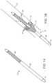
- FIGS. 1A-1Dshow an integrated valve system 10 having integrated embolic protection according to the present invention.
- a self-expanding, conical embolic filter 12is mounted on a shaft 14 of a balloon valve delivery catheter having a balloon-expandable prosthetic cardiac valve 20 mounted on a distal balloon 18.
- the balloon-expandable aortic valvemay be any one of a variety of available and proposed balloon expandable cardiac valves, such as an Edwards Sapien ® valve.
- the conical embolic filter 12may be mounted on the catheter shaft 14 with either a fixed attachment or a sliding attachment. A fixed attachment simplifies both construction and the deployment protocol but limits the ability to adjustably position the conical filter relative to the aortic valve during delivery.
- the distal end of the conical filterWhen fixedly attached, the distal end of the conical filter may be positioned from 1 cm to 20 cm proximal of the proximal end of the prosthetic valve 20, typically being from 1 cm to 10 cm proximal of the proximal end of the prosthetic valve.
- the distal end of the conical filterWhen slidably attached, the distal end of the conical filter may be adjusted (before or during deployment) to be positioned from 1 cm to 30 cm proximal of the proximal end of the prosthetic valve 20, typically being from 1 cm to 20 cm proximal of the proximal end of the prosthetic valve.
- the self-expanding, conical embolic filter 12typically comprises a mesh or other filter material having a mesh size suitable for embolic capture and a self-expanding support structure, such as a plurality of radially self-expanding struts 22 to ensure full expansion of the mesh or other filter material.
- a self-expanding support structuresuch as a plurality of radially self-expanding struts 22 to ensure full expansion of the mesh or other filter material.
- the radially self-expanding struts 22have atraumatic distal tips to contact the aortic wall, e.g. distal ends of the struts may be curved, coiled, have protective pads, or have other structures to inhibit tissue injury.
- the self-expanding, conical embolic filter 12is typically deployed by retracting a constraining sheath 26 (compare FIGS. 1A and 1B ) and may be collapsed by advancing the constraining sheath and/or retracting the catheter shaft 14 (compare FIGS. 1C and 1D ).
- the constraining sheathmay be used to cover the deflated balloon 18 as well as the conical filter ( FIG. 1D ).
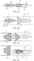
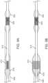
- FIGS. 2A-2Dshows a second embodiment of a valve system 210 having integrated embolic filter 212 on a catheter shaft 214 according to the present invention.
- the integrated valve system 210is adapted to deliver a self-expanding prosthetic valve 220, such as a Medtronic CoreValve ® heart valve mounted on a distal end of the catheter shaft 214.
- the self-expanding prosthetic valve 220is initially constrained for delivery by a first retractable constraining sheath 226, and the embolic filter 212 is initially constrained for delivery by a second retractable sheath 228.
- the filter 212is deployed by retraction of the second sheath 228, allowing the filter to expand ( FIG. 2B ).
- the prosthetic valve 220is then deployed by retraction of second retractable sheath 228 ( FIG. 2C ).
- the second retractable sheath 228is advanced to collapse the filter 212 and first sheath 226 for removal of the system. As shown in FIG.
- the first containing sheath 226may be collapsed within the collapsed filter 212 which in turn is collapsed in the second constraining sheath 228.
- the first retractable constraining sheath 226could be advanced prior to the collapse of the filter 212 by advancement of the second retractable sheath 228.
- the first constraining sheath 226would lie distal to the second retractable sheath 228 as the catheter shaft 14 is withdrawn from the aorta.
- FIGS. 3 and 4show a third embodiment of a valve system 310 having an integrated embolic filter assembly 312 on a catheter shaft 314 according to the present invention.
- the embolic filter assemblycomprises a distal cylindrical or panel-shaped deflector 312a (as described for example in US8,114,114 , the full disclosure of which is incorporated herein by reference) that is deployed across the great vessels of the aortic arch AA and a separate conical or other capture basket 312b that sits downstream or proximal of the deflector 312a in the descending aorta DA, as shown in FIG. 4 .
- the valve system 310will include a prosthetic valve 320 which may be positioned and deployed in the patient's aortic valve V using either the balloon expandable or the self-expanding protocols described previously.
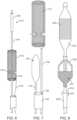
- FIG. 5Ashows a fourth embodiment of a valve system 510 having an integrated embolic filter in accordance with of the principles of the present invention.
- a proximal portion 513everts to form a flexible section that can be reversibly "rolled” to accommodate bidirectional axial movement of the catheter shaft 514 without while leaving a distal portion 516 of the embolic filter stationary against the vessel wall.
- Thisallows a proximal end of the embolic filter, which is fixed to the delivery catheter at an attachment junction 517, to move with the catheter shaft 514 as the catheter is advanced and retracted to position the valve for delivery without requiring the distal filter portion move and slide along the vessel wall as the catheter is advanced and retracted. Compare FIG.
- FIG. 5Bwhich shows the filter 512 deployed in the aortic arch AA prior to deployment of the prosthetic aortic valve 520
- FIG. 5Cwhich shows the filter 512 after the prosthetic valve 520 has been advanced into its deployment position within the native valve V.
- the attachment junction 517 of the proximal end of the embolic filter 512has advanced forward to allow the prosthetic valve 512 to be advanced into position without moving the main body of the embolic filter where it covers the cerebral branch vessels of the aortic arch AA.
- the filtermay be retracted back into the deployment sheath 526, as shown in FIG. 5D .
- FIG. 6shows a fifth embodiment of an embolic filter 612 in accordance with the present invention where the filter is mounted around a shaft 614 of a valve system 610 catheter during initial delivery.
- the shaft 614can move freely through an access port 616 that accommodates the catheter while inhibiting embolic debris release.
- the filter 612is held in position and recovered with a tether 618 that connects to a proximal end of the filter.
- the tether 618can be rigid to allow both proximal and distal repositioning, as well as retrieval. Retrieval can be accomplished by pulling the filter into a separate lumen of the delivery system (not shown).
- the filtercan be collapsed for retrieval via a mechanism such as a "purse string" loop 619 (shown) or elongation of a support frame.
- FIG. 7shows a sixth embodiment of an embolic filter 712 in accordance with the present invention in which a filter delivery sheath 726 is deployed and retrieved via a separate lumen 728 in a valve delivery catheter 730.
- the valve delivery catheter 730also has a lumen for a valve delivery shaft 714 which carries prosthetic valve 720.
- the prosthetic valve 720can be advanced through the embolic filter and to the valve implantation site.
- the filter catheter 726can be independently advanced and retracted so that it can be advanced ahead of the valve catheter 714 for deployment and positioning of the filter 720, and then withdrawn while the valve catheter is advanced past the filter catheter and through the access port of the filter mesh or other filter material.
- the valve catheter 714can be withdrawn and the filter catheter 726 advanced to assist in retrieval of the filter mesh or other filter material.
- FIG. 8shows a seventh embodiment of an embolic filter 812 in accordance with the present invention where the embolic filter is mounted with both ends of a filter support structure 822, such as self-expanding cage, attached to a delivery catheter 814.
- the embolic filter 812is open (free from the filter mesh) on its distal end and closed on its proximal direction for debris capture when deployed.
- At least one of the proximal end or distal end of the filter support structure 822is slidably attached to the delivery catheter 814 to allow radial opening and collapse.
- both the distal and proximal ends on the support structure 822will be slidably attached to catheter 814 to allow the balloon 818 and valve 820 to be positioned after the filter 812 is deployed.
- a conical guiding structure 827(funnel") at the end of the constraining sheath 826 assists in deployment and retrieval of the filter and support structure.
- FIGS. 9A-9Dshow an eighth embodiment of an embolic filter 912 in accordance with the present invention where both a prosthetic valve 920 and a filter 9 12 are balloon expandable.
- the embolic filter 912is mounted on a proximal-most balloon 916 of a double-balloon catheter 914.
- a balloon-expandable prosthetic valve 920such as an Edwards Lifesciences Sapien ® valve, is mounted on a distal-most balloon 922 on the catheter 914. Both the prosthetic valve 920 and the embolic filter 912 are thus deployed by balloon, where the balloons are configured to be inflated and deflated separately. As shown in FIG.
- the prosthetic valve 912 and the embolic filter 920are crimped onto balloons 916 and 922, respectively.
- the filter 912is deployed by inflation of balloon 916.
- the filter 920is then deployed by inflating balloon 922 ( FIG. 9C ), 922 is deflated once the filter has been deployed. While filter 912 remains expanded After valve deployment, balloon 922 is deflated, and a sheath 926 (previously used for deploying the valve delivery system) is advanced to collapse the filter 912 to allow removal of the system.
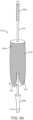
- FIG. 10shows a ninth embodiment of an embolic filter 1012 in accordance with the present invention.
- the embolic filter 1012is a self-supporting mesh basket with no additional support frame. It is deployed and retrieved by the retraction and advancement of a constraining sheath 1026 that is part of the delivery system of a balloon-expandable valve 1020, such as an Edwards Lifesciences Sapien ® valve.
- a constraining sheath 1026such as an Edwards Lifesciences Sapien ® valve.
- the embolic filter 1012is deployed via a self-expanding mechanism, while the prosthetic valve 1020 is deployed via the inflation of a deployment balloon 1022.
- the filter 1012may be mounted on a separate filter deployment catheter 1014, which is deployed over the balloon catheter 1016 but inside the constraining sheath 1026.
- the embolic filter 1012may be deployed either by retraction of the constraining sheath 1026, or advancement of the catheter 1014, to release the embolic filter from the constraining sheath.
- the prosthetic valve 1020is deployed by inflation of the deployment balloon 1022.
- the deployment balloon 1022is deflated, and the embolic filter 1012 is collapsed either by withdrawing the embolic filter into the constraining sheath 1026 or by advancing the constraining sheath over the embolic filter.
- Themay further comprise a downstream or proximal stop 1030 on a shaft of the catheter 1014 which limits proximal movement of the filter 1012 (when configured to slide on the shaft) on the shaft and an upstream or distal stop 1032 which limits distal movement of the filter on the shaft.
- the embolic filtermay be a mesh or other filter structure made of knitted, woven or nonwoven fibers, filaments or wires that will have a pore size chosen to allow blood to pass through but prevent emboli above a certain size from passing through.
- the embolic filtermay also consist of a non-woven sheet, such as a thin sheet of polymer or metal, that has been perforated with holes of a single size or different sizes.
- the embolic filter materialmay be made of a metal, a polymer or a combination thereof and may optionally have an antithrombogenic coating on its surface.
- the embolic filtermay also consist of some combination of a perforated sheet and a fiber-based mesh or other filter material or other filter structure.
- the embolic filtermay consist of a single layer or multiple layers of any of the above configurations to increase the filtering efficiency and reduce the effective pore size.
- the embolic protection deviceis delivered in an undeployed or retracted condition.
- a tubular outer delivery sheathmay be used to maintain the embolic protection device in the undeployed condition. ( FIG. 2A-2D ).
- the delivery cathetermay optionally include a shoulder or stop positioned proximal to the embolic protection device to maintain the position of the embolic protection device on the catheter as the delivery sheath is withdrawn during deployment.
- a pusher catheterthat fits in between the catheter and the delivery sheath may be used to facilitate deployment such as the filter deployment catheter in FIG. 10 .
- the filtermay be deployed via the inflation of balloon inside the filter, which may be cylindrically or conically shaped, or otherwise shaped to match the geometry of the filter.
- balloon inside the filterwhich may be cylindrically or conically shaped, or otherwise shaped to match the geometry of the filter.
- Such a filtermay be retrieved by withdrawing it into a retrieval sheath ( FIG. 9 ).
- Another alternative delivery mechanismis to reduce the effective length of the embolic filter with a member attached to either the distal or proximal end (or both).
- compressing the filter lengthwisewill result in expansion of the diameter of the filter structure and resultant deployment of the filter.
- the filtermay be elongated to reduce its diameter and collapse the filter. This can be accomplished with two independent filter deployment catheters that can be independently advanced or retracted to effect the change in length.
- the cathetermay be configured as a diagnostic catheter, a guiding catheter or therapeutic catheter.
- a specific examplewould be the delivery system for a transcatheter aortic valve.
- the embolic filterwill typically have at least one open end and define one or more internal collection regions which receive and capture emboli entering with blood flow through the open end.
- the embolic filtermay have two open ends, for example having a cylindrical configuration which allows blood to flow in one end and out from the other end.
- the filter membraneswill be self-supporting in the deployed condition.
- self-supportingit is meant that the filter membrane can be deployed without further support into a three-dimensional configuration that maintains sufficient contact with the vessel wall to form an adequate seal to prevent emboli above a certain size from passing around the outside of the embolic protection device.
- the embolic filtercan be constructed of a resilient mesh or other filter material that can be compressed into the undeployed condition and will self-expand into the deployed condition. Such structures are described in US 9,877,821 , previously incorporated herein by reference.
- the embolic filtermay comprise a filter membrane, matrix, or the like and a separate supporting structure.
- the filter membranemay comprise any known structure for filtering emboli from blood, including meshes, perforated sheets, porous sheets, fibrous structures, and the like, or any combinations thereof.
- the filter membranecan be resilient, slack, plastically deformable, or combinations thereof.
- the supporting structuremay be located externally to the filter membrane, internally within the filter membrane, or both eternally and internally.
- the supporting structuremay comprise a framework that includes one or more longitudinal struts or hoops that are attached to or otherwise engage the filter membrane to hold the filter membrane in its opened or deployed configuration with the aorta or other target blood vessel.
- the hoops and/or strutsmay be formed of a resilient metal, polymer, or other material to provide a self-expanding framework that assumes a low profile or narrow configuration when constrained by a sheath for delivery and which assumes an expanded or deployed configuration when released from constraint.
- the framework or other support structuremay comprise a malleable or plastically deformable material to provide expansion by applying a radial outward force to an interior of the support structure, typically using an inflatable balloon or other expansion mechanism.
- Hybrid constructionsthat combine features of the self-supporting structure and the frame-supported structure may also be used.
- Hybrid deployment methodssuch as balloon-assisted self-expansion or longitudinal compression of the support structure can also be utilized.
- embolic filtermay also be constructed with the embolic filter membrane being longer or shorter than the supporting structure.
- Specific relative longitudinal dimensions of the filter membranes of the embolic filtersmay be as shown in the drawings.
- the support structure and/or filter membranecan be conical with and enlarged or base end of the cone being positioned on the upstream side.
- the embolic filtercan be retracted and withdrawn with the catheter after the diagnostic or interventional procedure has been completed.
- the embolic filtermay include features to assist in retracting the device for retrieval from the patient's aorta.
- a conical guiding structuremay be slidably attached to the catheter at the proximal end of the device, the purpose of which is to assist the embolic filter in collapsing when a retrieval sheath is advanced along the conical guiding structure.
- portions of the embolic filtermay be constructed with retraction members that are configured like purse strings or lassos around the circumference of the device.
- a pull loop or other graspable structure near the downstream end of the embolic filteris connected to the retraction members by one or more connecting members.
- the embolic filteris configured to close its upstream end first to assure that any captured emboli do not migrate out of the filter during retrieval. This can be accomplished by providing one or more pull loops for selectively retracting different sections of the device.
- the retraction members and connecting membersmay be made of suture, wire, plastic filament or a combination of these materials.
- the "Stent" Support Structure described abovemay also be configured to serve as the retraction members.
- the embolic filtermay be fixedly attached to the catheter or attached via a slidable attachment, or some combination of the two.
- a sliding attachmentcan consist of one or more rings, roller bearings or other structures that allow the embolic protection device to slide freely on the catheter.
- the sliding attachmentwill preferably have a low coefficient of friction and/or a lubricious coating so that movement of a catheter through the sliding attachment will not jostle or dislodge the embolic protection device.
- the sliding attachmentcan contain an additional sealing element, such as resilient flaps, an iris structure, or an expandable sealing material.
- the overall undeployed diameter of the embolic filter as collapsed for delivery(including the diameter of its constraining sheath) preferably will be no larger than the largest section of the catheter (such as the collapsed diameter of a prosthetic valve, including its constraining sheath), which is most likely in the distal section of the catheter.
- the catheteris typically reduced in size proximal to the valve, which would potentially allow the integration of an embolic filter and its constraining member without changing the overall tracking profile of the valve delivery system.
- the embolic filteris in an undeployed condition on the catheter as it is inserted into a patient's aorta.
- the embolic filteris ideally deployed in the ascending aorta prior to the ostia of the cerebral arteries.
- a delivery sheathmay be used to hold the embolic filter in the undeployed position.
- the embolic filtercan also be constrained for delivery by crimping it onto a balloon catheter, or by elongating its support structure to reduce its diameter.
- the entire embolic filter or a portion of itmay be coated with an anti-thrombogenic coating, for example a bonded heparin coating, to reduce the formation of clots that could become potential emboli.
- the embolic filter or a portion of itmay have a drug-eluting coating containing an anti-inflammatory or anti-stenosis agent.
- the embolic filter of the present inventioncan also be used for embolic protection of other organ systems.
- an embolic filtercan be deployed in the patient's descending aorta for preventing embolic particles in the aortic blood flow from entering the renal arteries and embolizing in the patient's kidneys.
- Examples of the disclosureinclude the following examples:
Landscapes
- Health & Medical Sciences (AREA)
- Cardiology (AREA)
- Engineering & Computer Science (AREA)
- Life Sciences & Earth Sciences (AREA)
- General Health & Medical Sciences (AREA)
- Veterinary Medicine (AREA)
- Biomedical Technology (AREA)
- Heart & Thoracic Surgery (AREA)
- Public Health (AREA)
- Animal Behavior & Ethology (AREA)
- Transplantation (AREA)
- Oral & Maxillofacial Surgery (AREA)
- Vascular Medicine (AREA)
- Mechanical Engineering (AREA)
- Hematology (AREA)
- Anesthesiology (AREA)
- Pulmonology (AREA)
- Biophysics (AREA)
- Surgical Instruments (AREA)
- Prostheses (AREA)
- Media Introduction/Drainage Providing Device (AREA)
Abstract
Description
- This application claims the benefit of prior provisional patent applications Serial No.
62/844,941 (Attorney Docket No, 41959-714.102), filed on May 8, 2019 62/804,909 (Attorney Docket No 41959-714.101), filed on February 13, 2019 - 1.Field of the Invention. The present invention relates to apparatus and methods for providing embolic protection in a patient's vascular system. In particular, it relates to catheters intended for transcatheter heart valve delivery and other intravascular interventional procedures which incorporate an embolic filter.
- Cerebral embolism is a known complication of cardiac surgery, cardiopulmonary bypass and catheter-based interventional cardiology and electrophysiology procedures. Embolic particles, which may include thrombus, atheroma and lipids, may become dislodged by surgical or catheter manipulations and enter the bloodstream, embolizing in the brain or other vital organs downstream. Cerebral embolism can lead to neuropsychological deficits, stroke and even death. Other organs downstream can also be damaged by embolism, resulting in diminished function or organ failure.
- Prevention of embolism would benefit patients and improve the outcome of these procedures. Given that potential emboli are often dislodged during catheter-based procedures, it would be advantageous to deploy an embolic protection system as part of a catheter-based vascular procedure, such as transcatheter aortic valve replacement (TAVR). Further, the use of transcranial doppler (TCD) during TAVR has shown that cerebral emboli are generated primarily during the procedural steps of crossing the native valve and deploying the TAVR valve (ReferenceKahlert, et al, Circulation, 2012). Therefore, the integration of an embolic protection device on the TAVR delivery system itself would have the advantage that the protection is in place for the most critical steps of the procedure. Another advantage would come by integrating the embolic protection system on the catheter itself that is being used to perform the procedure, such as a transcatheter valve delivery system or electrophysiology catheter. Other embolic protection systems require separate procedural steps for installing the protector prior to the interventional or diagnostic procedure and removing it after the procedure. In many cases a different access site is required as well. The present invention avoids both the extra step and the need for an extra access site. Yet another advantage would come from providing an integrated embolic protection device that does not increase the overall diameter of the catheter.
- 2.Description of the Background Art. Devices for preventing embolisms and similar events are described in the following patents and patent applications, which are hereby incorporated by reference:
U.S. Pat. No. 10,166,094 U.S. Pat. No. US 9,877,821 U.S. Pat. No. 9,744,023 U.S. Pat. No. 9,144,485 U.S. Pat. No. 8,968,354 ;U.S. Pat. No. 8,740,930 ;U.S. Pat. No. 8,420,902 ;U.S. Pat. No. 8,383,788 ;U.S. Pat. No. 8,337,519 ;U.S. Pat. No. 8,123,779 ;U.S. Pat. No. 8,052,717 ;U.S. Pat. No. 7,537,600 ;U.S. Pat. No. 7,044,958 ;U.S. Pat. No. 6,537,297 ;U.S. Pat. No. 6,499,487 ;U.S. Pat. No. 6,371,935 ;U.S. Pat. No. 6,361,545 ;U.S. Pat. No. 6,254,563 ;U.S. Pat. No.6,139,517 ;U.S. Pat. No. 5,769,816 ;U.S. Pat. App. 2019/0015152 ;U.S. Pat. App. 2018/0206970 ;U.S. Pat. App. 2018/0042390 ;U.S. Pat. App. 2016/0317277 ;U.S. Pat. App. 2015/0366650 ;U.S. Pat. App. 2014/0214069 ;U.S. Pat. App. 2013/267993 ;U.S. Pat. App. 2012/271340 ;U.S. Pat. App. 2010/0312268 ;U.S. Pat. App. 2010/0010535 ;U.S. Pat. App. 2004/0215167 ;U.S. Pat. App. 2003/0100940 ; andPCT App. WO2004/019817 . - A prosthetic heart valve delivery catheter having integrated embolic protection according to the principles of the present invention inhibits the release of emboli into the aorta, the aortic arch or branch vessels, and other vasculature to protect the brain and other downstream organs from embolization during transvascular prosthetic heart valve replacement procedures. Unlike most other embolic protection solutions, the embolic filter is integrated into an interventional or diagnostic catheter, such as a transcatheter heart valve delivery system.
- In a first aspect, the present invention provides a prosthetic heart valve delivery catheter system having integrated embolic protection. The catheter system typically comprises a catheter shaft having a distal portion, a prosthetic valve disposed on the distal portion of the catheter shaft; and an embolic filter disposed on the distal portion of the shaft at a location proximal of the prosthetic valve. The embolic filter has a collapsed configuration and a deployed configuration, and an outer periphery of the filter is configured to contact a blood vessel wall in the expanded configuration. In some embodiments, the embolic filter comprises a filter structure having a narrow end coupled to the shaft and an open end located distally of the narrow end.
- In specific embodiments, the narrow end of the filter structure may fixedly attached to the catheter shaft. In alternative embodiments, the narrow end of the filter structure is slidably mounted on the catheter shaft. The catheter may further comprise at least one of a proximal stop on the catheter shaft for limiting proximal movement of the embolic filter on the distal portion of the catheter shaft and a distal stop on the catheter shaft for limiting distal movement of the embolic filter on the distal portion of the catheter shaft.
- In further specific embodiments, the filter may comprise a filter membrane and a support structure. The support structure may comprise a plurality of self-expanding axial struts connected at their proximal ends to the catheter shaft so as to open a distal end of the filter member to form a cone when released from constraint. The axial struts may have atraumatic distal tips.
- In other embodiments, the filter may comprise a self-expanding conical filter. For example, the embolic filter comprises a porous material comprising a fabric of knitted, woven, or nonwoven fibers, filaments, or wires. The porous material may be made of a resilient metal, polymer material, a malleable material, a plastically deformable material, a shape-memory material, or combinations thereof. The porous material will typically have a pore size chosen to prevent emboli over a predetermined size from passing through.
- In a second aspect, the present invention provides systems comprising a catheter as described above in combination with an outer delivery sheath configured to maintain the embolic filter in a collapsed configuration.
- In a third aspect, the present invention provides a prosthetic heart valve delivery catheter having integrated embolic protection. The prosthetic heart valve delivery catheter typically comprises a catheter shaft having a distal portion, a prosthetic valve disposed on the distal portion of the catheter shaft; and an embolic filter disposed on the distal portion of the shaft at a location proximal of the prosthetic valve. The embolic filter will usually have a collapsed configuration and a deployed configuration and, in the expanded configuration, an outer periphery of the filter contacts a blood vessel wall The embolic filter will typically comprise a filter membrane and a support structure, wherein the support structure comprises a cage having a distal collar and a proximal collar attached to the distal portion of the catheter shaft.
- In specific embodiments, at least one of the distal collar and the proximal collar is slidably attached to the distal portion of the catheter shaft. In other embodiments, at least one of the distal collar and the proximal collar is fixedly attached to the distal portion of the catheter shaft. For example, at least one of the distal collar and the proximal collar is fixedly attached to the distal portion of the catheter shaft. In other examples, at least one of the distal collar and the proximal collar is configured to be axially translated to expand and contract the cage. Typically, the cage is self-expanding so that it can be radially constrained for delivery and released from radial constraint for deployment. In still further examples, the cage has a conically tapered distal end, a conically tapered proximal end, and a cylindrical wall portion therebetween, wherein the filter membrane covers at least the conically tapered proximal end and does not cover the
- In a fourth aspect, the present invention provides a prosthetic heart valve delivery catheter having integrated embolic protection. The catheter comprises a catheter shaft having a distal portion, a prosthetic valve disposed on the distal portion of the catheter shaft, and an embolic filter disposed on the distal portion of the shaft at a location proximal of the prosthetic valve. The embolic filter typically has a collapsed configuration and a deployed configuration where an outer periphery of the filter is configured to contact a blood vessel wall. The embolic filter usually further comprises a cylindrical wall portion located proximal of the prosthetic valve and configured to cover a patient's aortic branch vessels and a conical wall portion proximal of the cylindrical wall portion.
- In specific embodiments, a cylindrical wall portion and a conical wall portion are not continuous. For example, at least one of cylindrical wall portion and the conical wall portion may be fixedly attached to the distal portion of the catheter shaft. In other examples, at least one of cylindrical wall portion and the conical wall portion is slidably attached to the distal portion of the catheter shaft. In still other examples, at least one of cylindrical wall portion and the conical wall portion is self-expanding. In any of these examples, at least one of cylindrical wall portion and the conical wall portion is balloon expandable.
- In a fifth aspect, the present invention provides a prosthetic heart valve delivery catheter having integrated embolic protection, where catheter comprises a catheter shaft having a distal portion, a prosthetic valve disposed on the distal portion of the catheter shaft, and an embolic filter disposed on the distal portion of the shaft at a location proximal of the prosthetic valve. The embolic filter typically has a collapsed configuration and a deployed configuration where an outer periphery of the filter is configured to contact a blood vessel wall. The embolic filter will usually further comprise a cylindrical wall having an open distal end and a closed proximal end sealing coupled to the catheter shaft, where a proximal region of the cylindrical wall is movably everted and allows the open distal end to axially translate relative to the catheter shaft while the closed proximal end remains stationary relative to the catheter shaft.
- In specific embodiments, the closed proximal end is fixed to the catheter shaft. For example,
the closed proximal end may slidably couple to the catheter shaft. At least the distal portion of the cylindrical wall may be self-expanding and at least at the distal portion of the cylindrical wall may comprise a self-expanding filter. - All publications, patents, and patent applications mentioned in this specification are herein incorporated by reference to the same extent as if each individual publication, patent, or patent application was specifically and individually indicated to be incorporated by reference.
- The novel features of the invention are set forth with particularity in the appended claims. A better understanding of the features and advantages of the present invention will be obtained by reference to the following detailed description that sets forth illustrative embodiments, in which the principles of the invention are utilized, and the accompanying drawings of which:
FIGS. 1A-1D shows a first embodiment of a valve delivery system according to the present invention with a balloon-deployable prosthetic cardiac valve having integrated embolic protection.FIGS. 2A-2D shows a second embodiment of a valve delivery system according to the present invention with a self-expanding prosthetic cardiac valve having integrated embolic protection.FIG. 3 shows a third embodiment of a valve delivery system according to the present invention with an integrated embolic protection including both an emboli deflector element and a separate emboli capture element.FIG. 4 illustrates the valve delivery system ifFIG. 3 deployed in an aortic arc with a prosthetic aortic valve being implanted in a native aortic valve.FIGS. 5A - 5D show a fourth embodiment of a valve delivery system according to the present invention having an elongated cylindrical filter mesh deployed over an aortic arch while delivering a prosthetic aortic valve in a native aortic valve.FIG. 6 shows a fifth embodiment of a valve delivery system according to the present invention having an embolic filter that is mounted around the valve system catheter during initial delivery.FIG. 7 shows a sixth embodiment of a valve delivery system according to the present invention having a prosthetic valve and embolic filter similar to those ofFIG. 6 where a filter delivery sheath is deployed and retrieved via a separate catheter in a separate lumen of the valve delivery catheter located adjacent to the catheter that contains the prosthetic valve.FIG. 8 shows a seventh embodiment of a valve delivery system according to the present invention having an embolic filter mounted on a valve delivery system with both ends of a support structure attached to the delivery catheter.FIGS. 9A-9D show an eighth embodiment of a valve delivery system according to the present invention similar to the valve delivery system ofFIG. 1 .FIG. 10 shows a ninth embodiment of a valve delivery system according to the present invention similar to that ofFIG. 1 where the embolic filter comprises a self-supporting mesh basket with no additional support frame.- For purposes of this patent application, the term "distal" refers to the end of the device that is farthest away from the operator, and closest to the heart. This is also the "upstream" direction of blood flow. The term "proximal" refers to the end of the device nearer to the operator, toward the direction of the access site where the device has been introduced into the body, and farthest away from the heart. This is also the "downstream" direction of blood flow.
FIGS. 1A-1D show anintegrated valve system 10 having integrated embolic protection according to the present invention. A self-expanding, conicalembolic filter 12 is mounted on ashaft 14 of a balloon valve delivery catheter having a balloon-expandable prostheticcardiac valve 20 mounted on adistal balloon 18. The balloon-expandable aortic valve may be any one of a variety of available and proposed balloon expandable cardiac valves, such as an Edwards Sapien® valve. The conicalembolic filter 12 may be mounted on thecatheter shaft 14 with either a fixed attachment or a sliding attachment. A fixed attachment simplifies both construction and the deployment protocol but limits the ability to adjustably position the conical filter relative to the aortic valve during delivery. When fixedly attached, the distal end of the conical filter may be positioned from 1 cm to 20 cm proximal of the proximal end of theprosthetic valve 20, typically being from 1 cm to 10 cm proximal of the proximal end of the prosthetic valve. When slidably attached, the distal end of the conical filter may be adjusted (before or during deployment) to be positioned from 1 cm to 30 cm proximal of the proximal end of theprosthetic valve 20, typically being from 1 cm to 20 cm proximal of the proximal end of the prosthetic valve.- The self-expanding, conical
embolic filter 12 typically comprises a mesh or other filter material having a mesh size suitable for embolic capture and a self-expanding support structure, such as a plurality of radially self-expandingstruts 22 to ensure full expansion of the mesh or other filter material. As illustrated, the radially self-expandingstruts 22 have atraumatic distal tips to contact the aortic wall, e.g. distal ends of the struts may be curved, coiled, have protective pads, or have other structures to inhibit tissue injury. - The self-expanding, conical
embolic filter 12 is typically deployed by retracting a constraining sheath 26 (compareFIGS. 1A and 1B ) and may be collapsed by advancing the constraining sheath and/or retracting the catheter shaft 14 (compareFIGS. 1C and 1D ). Optionally, after deployment of thevalve 20, the constraining sheath may be used to cover the deflatedballoon 18 as well as the conical filter (FIG. 1D ). FIGS. 2A-2D shows a second embodiment of avalve system 210 having integratedembolic filter 212 on acatheter shaft 214 according to the present invention. Theintegrated valve system 210 is adapted to deliver a self-expandingprosthetic valve 220, such as a Medtronic CoreValve® heart valve mounted on a distal end of thecatheter shaft 214. The self-expandingprosthetic valve 220 is initially constrained for delivery by a first retractable constrainingsheath 226, and theembolic filter 212 is initially constrained for delivery by a secondretractable sheath 228.- After positioning the first constraining
sheath 226 andprosthetic valve 220 in the aortic valve V, thefilter 212 is deployed by retraction of thesecond sheath 228, allowing the filter to expand (FIG. 2B ). Theprosthetic valve 220 is then deployed by retraction of second retractable sheath 228 (FIG. 2C ). After valve deployment, the secondretractable sheath 228 is advanced to collapse thefilter 212 andfirst sheath 226 for removal of the system. As shown inFIG. 2D , the first containingsheath 226 may be collapsed within thecollapsed filter 212 which in turn is collapsed in the second constraining sheath 228.Alternatively, the first retractable constrainingsheath 226 could be advanced prior to the collapse of thefilter 212 by advancement of the secondretractable sheath 228. In this alternative, the first constrainingsheath 226 would lie distal to the secondretractable sheath 228 as thecatheter shaft 14 is withdrawn from the aorta. FIGS. 3 and4 show a third embodiment of avalve system 310 having an integrated embolic filter assembly 312 on acatheter shaft 314 according to the present invention. The embolic filter assembly comprises a distal cylindrical or panel-shapeddeflector 312a (as described for example inUS8,114,114 , the full disclosure of which is incorporated herein by reference) that is deployed across the great vessels of the aortic arch AA and a separate conical orother capture basket 312b that sits downstream or proximal of thedeflector 312a in the descending aorta DA, as shown inFIG. 4 . Thevalve system 310 will include aprosthetic valve 320 which may be positioned and deployed in the patient's aortic valve V using either the balloon expandable or the self-expanding protocols described previously.FIG. 5A shows a fourth embodiment of avalve system 510 having an integrated embolic filter in accordance with of the principles of the present invention. Aproximal portion 513 everts to form a flexible section that can be reversibly "rolled" to accommodate bidirectional axial movement of thecatheter shaft 514 without while leaving adistal portion 516 of the embolic filter stationary against the vessel wall. This allows a proximal end of the embolic filter, which is fixed to the delivery catheter at anattachment junction 517, to move with thecatheter shaft 514 as the catheter is advanced and retracted to position the valve for delivery without requiring the distal filter portion move and slide along the vessel wall as the catheter is advanced and retracted. CompareFIG. 5B which shows thefilter 512 deployed in the aortic arch AA prior to deployment of the prostheticaortic valve 520 andFIG. 5C which shows thefilter 512 after theprosthetic valve 520 has been advanced into its deployment position within the native valve V. Note that theattachment junction 517 of the proximal end of theembolic filter 512 has advanced forward to allow theprosthetic valve 512 to be advanced into position without moving the main body of the embolic filter where it covers the cerebral branch vessels of the aortic arch AA. After deployment of thevalve 512, the filter may be retracted back into thedeployment sheath 526, as shown inFIG. 5D .FIG. 6 shows a fifth embodiment of anembolic filter 612 in accordance with the present invention where the filter is mounted around ashaft 614 of avalve system 610 catheter during initial delivery. After deployment of thefilter 612, theshaft 614 can move freely through anaccess port 616 that accommodates the catheter while inhibiting embolic debris release. Thefilter 612 is held in position and recovered with atether 618 that connects to a proximal end of the filter. Thetether 618 can be rigid to allow both proximal and distal repositioning, as well as retrieval. Retrieval can be accomplished by pulling the filter into a separate lumen of the delivery system (not shown). The filter can be collapsed for retrieval via a mechanism such as a "purse string" loop 619 (shown) or elongation of a support frame.FIG. 7 shows a sixth embodiment of anembolic filter 712 in accordance with the present invention in which afilter delivery sheath 726 is deployed and retrieved via aseparate lumen 728 in avalve delivery catheter 730. Thevalve delivery catheter 730 also has a lumen for avalve delivery shaft 714 which carriesprosthetic valve 720. Upon deployment of the embolic filter712, theprosthetic valve 720 can be advanced through the embolic filter and to the valve implantation site. Thefilter catheter 726 can be independently advanced and retracted so that it can be advanced ahead of thevalve catheter 714 for deployment and positioning of thefilter 720, and then withdrawn while the valve catheter is advanced past the filter catheter and through the access port of the filter mesh or other filter material. After valve deployment, thevalve catheter 714 can be withdrawn and thefilter catheter 726 advanced to assist in retrieval of the filter mesh or other filter material.FIG. 8 shows a seventh embodiment of anembolic filter 812 in accordance with the present invention where the embolic filter is mounted with both ends of afilter support structure 822, such as self-expanding cage, attached to adelivery catheter 814. Theembolic filter 812 is open (free from the filter mesh) on its distal end and closed on its proximal direction for debris capture when deployed. At least one of the proximal end or distal end of thefilter support structure 822 is slidably attached to thedelivery catheter 814 to allow radial opening and collapse. In some instances, both the distal and proximal ends on thesupport structure 822 will be slidably attached tocatheter 814 to allow theballoon 818 andvalve 820 to be positioned after thefilter 812 is deployed.
A conical guiding structure 827 ("funnel") at the end of the constrainingsheath 826 assists in deployment and retrieval of the filter and support structure.FIGS. 9A-9D show an eighth embodiment of anembolic filter 912 in accordance with the present invention where both aprosthetic valve 920 and a filter 9 12 are balloon expandable. Theembolic filter 912 is mounted on aproximal-most balloon 916 of a double-balloon catheter 914. A balloon-expandableprosthetic valve 920, such as an Edwards Lifesciences Sapien® valve, is mounted on adistal-most balloon 922 on thecatheter 914. Both theprosthetic valve 920 and theembolic filter 912 are thus deployed by balloon, where the balloons are configured to be inflated and deflated separately. As shown inFIG. 9A , prior to deployment, theprosthetic valve 912 and theembolic filter 920 are crimped ontoballoons FIG. 9B , thefilter 912 is deployed by inflation ofballoon 916. Thefilter 920 is then deployed by inflating balloon 922 (FIG. 9C ), 922 is deflated once the filter has been deployed. Whilefilter 912 remains expanded After valve deployment,balloon 922 is deflated, and a sheath 926 (previously used for deploying the valve delivery system) is advanced to collapse thefilter 912 to allow removal of the system.FIG. 10 shows a ninth embodiment of anembolic filter 1012 in accordance with the present invention. Theembolic filter 1012 is a self-supporting mesh basket with no additional support frame. It is deployed and retrieved by the retraction and advancement of a constrainingsheath 1026 that is part of the delivery system of a balloon-expandable valve 1020, such as an Edwards Lifesciences Sapien® valve. In this example, theembolic filter 1012 is deployed via a self-expanding mechanism, while theprosthetic valve 1020 is deployed via the inflation of adeployment balloon 1022. Thefilter 1012 may be mounted on a separatefilter deployment catheter 1014, which is deployed over theballoon catheter 1016 but inside the constrainingsheath 1026. This configuration allows theballoon catheter 1016 to be advanced and withdrawn independent of thefilter deployment catheter 1014 and related mechanism. Theembolic filter 1012 may be deployed either by retraction of the constrainingsheath 1026, or advancement of thecatheter 1014, to release the embolic filter from the constraining sheath. After filter deployment, theprosthetic valve 1020 is deployed by inflation of thedeployment balloon 1022. After thevalve 1020 has been deployed, thedeployment balloon 1022 is deflated, and theembolic filter 1012 is collapsed either by withdrawing the embolic filter into the constrainingsheath 1026 or by advancing the constraining sheath over the embolic filter. The may further comprise a downstream orproximal stop 1030 on a shaft of thecatheter 1014 which limits proximal movement of the filter 1012 (when configured to slide on the shaft) on the shaft and an upstream ordistal stop 1032 which limits distal movement of the filter on the shaft.- The embolic filter may be a mesh or other filter structure made of knitted, woven or nonwoven fibers, filaments or wires that will have a pore size chosen to allow blood to pass through but prevent emboli above a certain size from passing through. The embolic filter may also consist of a non-woven sheet, such as a thin sheet of polymer or metal, that has been perforated with holes of a single size or different sizes. The embolic filter material may be made of a metal, a polymer or a combination thereof and may optionally have an antithrombogenic coating on its surface. The embolic filter may also consist of some combination of a perforated sheet and a fiber-based mesh or other filter material or other filter structure. The embolic filter may consist of a single layer or multiple layers of any of the above configurations to increase the filtering efficiency and reduce the effective pore size.
- The embolic protection device is delivered in an undeployed or retracted condition. A tubular outer delivery sheath may be used to maintain the embolic protection device in the undeployed condition. (
FIG. 2A-2D ). The delivery catheter may optionally include a shoulder or stop positioned proximal to the embolic protection device to maintain the position of the embolic protection device on the catheter as the delivery sheath is withdrawn during deployment. Alternatively, a pusher catheter that fits in between the catheter and the delivery sheath may be used to facilitate deployment such as the filter deployment catheter inFIG. 10 . - Alternatively, the filter may be deployed via the inflation of balloon inside the filter, which may be cylindrically or conically shaped, or otherwise shaped to match the geometry of the filter. Such a filter may be retrieved by withdrawing it into a retrieval sheath (
FIG. 9 ). - Another alternative delivery mechanism is to reduce the effective length of the embolic filter with a member attached to either the distal or proximal end (or both). In an embolic filter with a design such as shown in
FIGS. 2A-2D , compressing the filter lengthwise will result in expansion of the diameter of the filter structure and resultant deployment of the filter. During retrieval, the filter may be elongated to reduce its diameter and collapse the filter. This can be accomplished with two independent filter deployment catheters that can be independently advanced or retracted to effect the change in length. - The catheter may be configured as a diagnostic catheter, a guiding catheter or therapeutic catheter. A specific example would be the delivery system for a transcatheter aortic valve.
- The embolic filter will typically have at least one open end and define one or more internal collection regions which receive and capture emboli entering with blood flow through the open end. In other configurations, the embolic filter may have two open ends, for example having a cylindrical configuration which allows blood to flow in one end and out from the other end.
- In many embodiments, the filter membranes will be self-supporting in the deployed condition. By self-supporting it is meant that the filter membrane can be deployed without further support into a three-dimensional configuration that maintains sufficient contact with the vessel wall to form an adequate seal to prevent emboli above a certain size from passing around the outside of the embolic protection device. In one example, the embolic filter can be constructed of a resilient mesh or other filter material that can be compressed into the undeployed condition and will self-expand into the deployed condition. Such structures are described in
US 9,877,821 - In another example, the embolic filter may comprise a filter membrane, matrix, or the like and a separate supporting structure. The filter membrane may comprise any known structure for filtering emboli from blood, including meshes, perforated sheets, porous sheets, fibrous structures, and the like, or any combinations thereof. The filter membrane can be resilient, slack, plastically deformable, or combinations thereof.
- The supporting structure may be located externally to the filter membrane, internally within the filter membrane, or both eternally and internally. For example, the supporting structure may comprise a framework that includes one or more longitudinal struts or hoops that are attached to or otherwise engage the filter membrane to hold the filter membrane in its opened or deployed configuration with the aorta or other target blood vessel. The hoops and/or struts may be formed of a resilient metal, polymer, or other material to provide a self-expanding framework that assumes a low profile or narrow configuration when constrained by a sheath for delivery and which assumes an expanded or deployed configuration when released from constraint. Alternatively, the framework or other support structure may comprise a malleable or plastically deformable material to provide expansion by applying a radial outward force to an interior of the support structure, typically using an inflatable balloon or other expansion mechanism.
- Hybrid constructions that combine features of the self-supporting structure and the frame-supported structure may also be used. Hybrid deployment methods, such as balloon-assisted self-expansion or longitudinal compression of the support structure can also be utilized.
- The support structures and the filter membranes of the embolic filters will often have the same lengths, but embolic filter may also be constructed with the embolic filter membrane being longer or shorter than the supporting structure. Specific relative longitudinal dimensions of the filter membranes of the embolic filters may be as shown in the drawings. In another alternate construction, the support structure and/or filter membrane can be conical with and enlarged or base end of the cone being positioned on the upstream side.
- The embolic filter can be retracted and withdrawn with the catheter after the diagnostic or interventional procedure has been completed. Optionally, the embolic filter may include features to assist in retracting the device for retrieval from the patient's aorta. For example, a conical guiding structure may be slidably attached to the catheter at the proximal end of the device, the purpose of which is to assist the embolic filter in collapsing when a retrieval sheath is advanced along the conical guiding structure. In another example, portions of the embolic filter may be constructed with retraction members that are configured like purse strings or lassos around the circumference of the device. A pull loop or other graspable structure near the downstream end of the embolic filter is connected to the retraction members by one or more connecting members. In one preferred embodiment, the embolic filter is configured to close its upstream end first to assure that any captured emboli do not migrate out of the filter during retrieval. This can be accomplished by providing one or more pull loops for selectively retracting different sections of the device. The retraction members and connecting members may be made of suture, wire, plastic filament or a combination of these materials. In an alternate construction, the "Stent" Support Structure described above may also be configured to serve as the retraction members.
- The embolic filter may be fixedly attached to the catheter or attached via a slidable attachment, or some combination of the two. A sliding attachment can consist of one or more rings, roller bearings or other structures that allow the embolic protection device to slide freely on the catheter. The sliding attachment will preferably have a low coefficient of friction and/or a lubricious coating so that movement of a catheter through the sliding attachment will not jostle or dislodge the embolic protection device. Alternatively, the sliding attachment can contain an additional sealing element, such as resilient flaps, an iris structure, or an expandable sealing material.
- The overall undeployed diameter of the embolic filter as collapsed for delivery (including the diameter of its constraining sheath) preferably will be no larger than the largest section of the catheter (such as the collapsed diameter of a prosthetic valve, including its constraining sheath), which is most likely in the distal section of the catheter. In the case of a valve delivery system, the catheter is typically reduced in size proximal to the valve, which would potentially allow the integration of an embolic filter and its constraining member without changing the overall tracking profile of the valve delivery system.
- The embolic filter is in an undeployed condition on the catheter as it is inserted into a patient's aorta. The embolic filter is ideally deployed in the ascending aorta prior to the ostia of the cerebral arteries. Optionally, a delivery sheath may be used to hold the embolic filter in the undeployed position. The embolic filter can also be constrained for delivery by crimping it onto a balloon catheter, or by elongating its support structure to reduce its diameter.
- The entire embolic filter or a portion of it may be coated with an anti-thrombogenic coating, for example a bonded heparin coating, to reduce the formation of clots that could become potential emboli. Alternatively, or in addition, the embolic filter or a portion of it may have a drug-eluting coating containing an anti-inflammatory or anti-stenosis agent. The embolic filter of the present invention can also be used for embolic protection of other organ systems. For example, an embolic filter can be deployed in the patient's descending aorta for preventing embolic particles in the aortic blood flow from entering the renal arteries and embolizing in the patient's kidneys.
- While preferred embodiments of the present invention have been shown and described herein, it will be obvious to those skilled in the art that such embodiments are provided by way of example only. Numerous variations, changes, and substitutions will now occur to those skilled in the art without departing from the invention. It should be understood that various alternatives to the embodiments of the invention described herein may be employed in practicing the invention. It is intended that the following claims define the scope of the invention and that methods and structures within the scope of these claims and their equivalents be covered thereby.
- Example 1: A prosthetic heart valve delivery catheter having integrated embolic protection, said catheter comprising:
- a catheter shaft having a distal portion;
- a prosthetic valve disposed on the distal portion of the catheter shaft; and
- an embolic filter disposed on the distal portion of the shaft at a location proximal of the prosthetic valve, said embolic filter having a collapsed configuration and a deployed configuration wherein an outer periphery of the filter is configured to contact a blood vessel wall;
- wherein the embolic filter comprises a filter structure having a narrow end coupled to the shaft and an open end located distally of the narrow end.
- Example 2: The catheter of example 1, wherein the narrow end of the filter structure is fixedly attached to the catheter shaft.
- Example 3: The catheter of example 1, wherein the narrow end of the filter structure is slidably mounted on the catheter shaft.
- Example 4: The catheter of example 3, further comprising a proximal stop on the catheter shaft for limiting proximal movement of the embolic filter on the distal portion of the catheter shaft.
- Example 5: The catheter of example 4, further comprising a distal stop on the catheter shaft for limiting distal movement of the embolic filter on the distal portion of the catheter shaft.
- Example 6: The catheter of example 1, wherein the filter comprises a filter membrane and a support structure.
- Example 7: The catheter of example 6, wherein the support structure comprises a plurality of self-expanding axial struts connected at their proximal ends to the catheter shaft so as to open a distal end of the filter member to form a cone when released from constraint.
- Example 8: The catheter of example 7, wherein the axial struts have atraumatic distal tips.
- Example 9: The catheter of example 1, wherein the filter comprises a self-expanding conical filter.
- Example 10: The catheter of example 1, wherein the embolic filter comprises a porous material comprising a fabric of knitted, woven, or nonwoven fibers, filaments, or wires.
- Example 11. The catheter of example 10, wherein the porous material is made of a resilient metal, polymer material, a malleable material, a plastically deformable material, a shape-memory material, or combinations thereof.
- Example 12. The catheter of example 10, wherein the porous material has a pore size chosen to prevent emboli over a predetermined size from passing through.
- Example 13. A system comprising;
- the catheter of example 1; and
- an outer delivery sheath configured to maintain the embolic filter in a collapsed configuration.
- Example 14. A prosthetic heart valve delivery catheter having integrated embolic protection, said catheter comprising:
- a catheter shaft having a distal portion;
- a prosthetic valve disposed on the distal portion of the catheter shaft; and
- an embolic filter disposed on the distal portion of the shaft at a location proximal of the prosthetic valve, said embolic filter having a collapsed configuration and a deployed configuration wherein an outer periphery of the filter is configured to contact a blood vessel wall;
- wherein the embolic filter comprises a filter membrane and a support structure,
- wherein the support structure comprises a cage having a distal collar and a proximal collar attached to the distal portion of the catheter shaft.
- Example 15: The catheter of example 1, wherein at least one of the distal collar and the proximal collar is slidably attached to the distal portion of the catheter shaft.
- Example 16: The catheter of example 1, wherein at least one of the distal collar and the proximal collar is fixedly attached to the distal portion of the catheter shaft.
- Example 17: The catheter of example 1, wherein at least one of the distal collar and the proximal collar is fixedly attached to the distal portion of the catheter shaft.
- Example 18: The catheter of example 1, wherein at least one of the distal collar and the proximal collar is configured to be axially translated to expand and contract the cage.
- Example 19: The catheter of example 1, wherein the cage is self-expanding so that it can be radially constrained for delivery and released from radial constraint for deployment.
- Example 20: The catheter of example 1, wherein the cage has a conically tapered distal end, a conically tapered proximal end, and a cylindrical wall portion therebetween, wherein the
filter membrane covers at least the conically tapered proximal end and does not cover the conically tapered distal end. - Example 21: A prosthetic heart valve delivery catheter having integrated embolic protection, said catheter comprising:
- a catheter shaft having a distal portion;
- a prosthetic valve disposed on the distal portion of the catheter shaft; and an embolic filter disposed on the distal portion of the shaft at a location proximal of the prosthetic valve, said embolic filter having a collapsed configuration and a deployed configuration wherein an outer periphery of the filter is configured to contact a blood vessel wall;
- wherein the embolic filter comprises a cylindrical wall portion located proximal of the prosthetic valve and configured to cover a patient's aortic branch vessels and a conical wall
- portion proximal of the cylindrical wall portion.
- Example 22. The catheter of example 21, wherein cylindrical wall portion and a conical wall portion are not continuous.
- Example 23: The catheter of example 21, wherein at least one of cylindrical wall portion and the conical wall portion is fixedly attached to the distal portion of the catheter shaft.
- Example 24: The catheter of example 21, wherein at least one of cylindrical wall portion and the conical wall portion is slidably attached to the distal portion of the catheter shaft.
- Example 25: The catheter of example 21, wherein at least one of cylindrical wall portion and the conical wall portion is self-expanding.
- Example 26: The catheter of example 1, The catheter of example 1, wherein at least one of cylindrical wall portion and the conical wall portion is balloon expandable.
- Example 27: A prosthetic heart valve delivery catheter having integrated embolic protection, said catheter comprising:
- a catheter shaft having a distal portion;
- a prosthetic valve disposed on the distal portion of the catheter shaft; and
- an embolic filter disposed on the distal portion of the shaft at a location proximal of the prosthetic valve, said embolic filter having a collapsed configuration and a deployed configuration wherein an outer periphery of the filter is configured to contact a blood vessel wall;
- wherein the embolic filter comprises a cylindrical wall having an open distal end and a closed proximal end sealing coupled to the catheter shaft, wherein a proximal region of the
- cylindrical wall is movably everted and allows the open distal end to axially translate relative to
- the catheter shaft while the closed proximal end remains stationary relative to the catheter shaft.
- Example 28: The catheter of example 27, wherein the closed proximal end is fixed to the catheter shaft.
- Example 29. The catheter of example 27, wherein the closed proximal end is slidably coupled to the catheter shaft.
- Example 30: The catheter of example 1, wherein at least the distal portion of the cylindrical wall is self-expanding.
- Example 31: The catheter of example 1, wherein at least the distal portion of the cylindrical wall comprises a self-expanding filter.
Claims (15)
1. A catheter with an embolic protection filter, said catheter comprising:
a catheter shaft having a distal portion;
an embolic filter disposed on the distal portion of the shaft, said embolic filter having a collapsed configuration and a deployed configuration wherein an outer periphery of the filter is configured to contact a blood vessel wall;
wherein the embolic filter comprises a filter structure having a narrow end coupled to the shaft and an open end located distally of the narrow end.
2. The catheter of any of claim 1, wherein the narrow end of the filter structure is fixedly attached to the catheter shaft.
3. The catheter of any of claims 1 to 2, wherein the narrow end of the filter structure is slidably mounted on the catheter shaft
4. The catheter of claim 3, further comprising a proximal stop on the catheter shaft for limiting proximal movement of the embolic filter on the distal portion of the catheter shaft
5. The catheter of claim 4, further comprising a distal stop on the catheter shaft for limiting distal movement of the embolic filter on the distal portion of the catheter shaft
6. The catheter of any one of claims 1 to 5, wherein the embolic filter comprises a filter membrane and a support structure.
7. The catheter of claim 6, wherein the support structure comprises a plurality of self-expanding axial struts connected at their proximal ends to the catheter shaft so as to open a distal end of the filter member to form a cone when released from constraint.
8. The catheter of claim 7, wherein the axial struts have atraumatic distal tips.
9. The catheter of any one of claims 1 to 8, wherein the filter comprises a self-expanding filter.
10. The catheter of any one of claims 1 to 9, wherein the embolic filter comprises a porous material comprising a fabric of knitted, woven, or nonwoven fibers, filaments, or wires.
11. The catheter of claim 10, wherein the porous material is made of a resilient metal, polymer material, a malleable material, a plastically deformable material, a shape-memory material, or combinations thereof.
12. The catheter of any of claims 1 to 11, wherein said filter structure has a conical shape.
13. The catheter of any of claims 1 to 12, wherein a first sheath is configured to constrain the embolic filter, and wherein said first sheath is configured to retract to allow said embolic filter to expand.
12. The catheter of claim 10, wherein the porous material has a pore size chosen to prevent emboli over a predetermined size from passing through.
13. A system comprising;
the catheter of any one of claims 1 to 12; and
an outer delivery sheath configured to maintain the embolic filter in a collapsed configuration.
Applications Claiming Priority (4)
| Application Number | Priority Date | Filing Date | Title |
|---|---|---|---|
| US201962804909P | 2019-02-13 | 2019-02-13 | |
| US201962844941P | 2019-05-08 | 2019-05-08 | |
| EP20755499.9AEP3923861B1 (en) | 2019-02-13 | 2020-02-13 | Catheter with integrated embolic protection device |
| PCT/US2020/018128WO2020168091A1 (en) | 2019-02-13 | 2020-02-13 | Catheter with integrated embolic protection device |
Related Parent Applications (1)
| Application Number | Title | Priority Date | Filing Date |
|---|---|---|---|
| EP20755499.9ADivisionEP3923861B1 (en) | 2019-02-13 | 2020-02-13 | Catheter with integrated embolic protection device |
Publications (2)
| Publication Number | Publication Date |
|---|---|
| EP4541316A2true EP4541316A2 (en) | 2025-04-23 |
| EP4541316A3 EP4541316A3 (en) | 2025-07-09 |
Family
ID=71944942
Family Applications (2)
| Application Number | Title | Priority Date | Filing Date |
|---|---|---|---|
| EP20755499.9AActiveEP3923861B1 (en) | 2019-02-13 | 2020-02-13 | Catheter with integrated embolic protection device |
| EP24213458.3APendingEP4541316A3 (en) | 2019-02-13 | 2020-02-13 | Catheter with integrated embolic protection device |
Family Applications Before (1)
| Application Number | Title | Priority Date | Filing Date |
|---|---|---|---|
| EP20755499.9AActiveEP3923861B1 (en) | 2019-02-13 | 2020-02-13 | Catheter with integrated embolic protection device |
Country Status (6)
| Country | Link |
|---|---|
| US (2) | US11304792B2 (en) |
| EP (2) | EP3923861B1 (en) |
| JP (2) | JP7557475B2 (en) |
| KR (2) | KR20210126681A (en) |
| CN (1) | CN113677296B (en) |
| WO (1) | WO2020168091A1 (en) |
Families Citing this family (9)
| Publication number | Priority date | Publication date | Assignee | Title |
|---|---|---|---|---|
| RU2014129392A (en) | 2012-01-06 | 2016-02-27 | Эмболайн, Инк. | Embedded anti-embolic protection |
| US10617509B2 (en) | 2015-12-29 | 2020-04-14 | Emboline, Inc. | Multi-access intraprocedural embolic protection device |
| KR20210126681A (en) | 2019-02-13 | 2021-10-20 | 엠볼린, 인크. | Catheter with integrated embolic protection |
| US11707351B2 (en) | 2019-08-19 | 2023-07-25 | Encompass Technologies, Inc. | Embolic protection and access system |
| CN112057203A (en)* | 2020-09-29 | 2020-12-11 | 孙涌泉 | Embolism protector for aortic valve operation |
| KR20230147061A (en)* | 2021-02-19 | 2023-10-20 | 엠볼린, 인크. | Method and system for placing embolic filters in the aortic arch |
| EP4112005A1 (en)* | 2021-07-01 | 2023-01-04 | Medtronic Inc. | A delivery catheter system |
| CN113520674B (en)* | 2021-07-16 | 2024-09-27 | 湖南埃普特医疗器械有限公司 | A valve expansion protection device |
| US12232948B2 (en)* | 2022-08-23 | 2025-02-25 | Transaortic Medical, Inc. | Embolic protection system |
Citations (28)
| Publication number | Priority date | Publication date | Assignee | Title |
|---|---|---|---|---|
| US5769816A (en) | 1995-11-07 | 1998-06-23 | Embol-X, Inc. | Cannula with associated filter |
| US6139517A (en) | 1997-12-15 | 2000-10-31 | Cardeon Corporation | Perfusion shunt apparatus and method |
| US6254563B1 (en) | 1997-12-15 | 2001-07-03 | Cardeon Corporation | Perfusion shunt apparatus and method |
| US6361545B1 (en) | 1997-09-26 | 2002-03-26 | Cardeon Corporation | Perfusion filter catheter |
| US6371935B1 (en) | 1999-01-22 | 2002-04-16 | Cardeon Corporation | Aortic catheter with flow divider and methods for preventing cerebral embolization |
| US6499487B1 (en) | 1997-12-23 | 2002-12-31 | Embol-X, Inc. | Implantable cerebral protection device and methods of use |
| US6537297B2 (en) | 1997-05-08 | 2003-03-25 | Embol-X, Inc. | Methods of protecting a patient from embolization during surgery |
| US20030100940A1 (en) | 2001-11-23 | 2003-05-29 | Mindguard Ltd. | Implantable intraluminal protector device and method of using same for stabilizing atheromas |
| WO2004019817A1 (en) | 2002-08-27 | 2004-03-11 | Amir Belson | Embolic protection device |
| US7044958B2 (en) | 2001-04-03 | 2006-05-16 | Medtronic Vascular, Inc. | Temporary device for capturing embolic material |
| US7537600B2 (en) | 2003-06-12 | 2009-05-26 | Boston Scientific Scimed, Inc. | Valved embolic protection filter |
| US20100010535A1 (en) | 2008-07-14 | 2010-01-14 | Boston Scientific Scimed, Inc. | Embolic protection device |
| US20100312268A1 (en) | 2006-11-29 | 2010-12-09 | Amir Belson | Embolic protection device |
| US8052717B2 (en) | 2008-07-14 | 2011-11-08 | Boston Scientific Scimed, Inc. | Embolic protection device |
| US8123779B2 (en) | 2002-12-30 | 2012-02-28 | Boston Scientific Scimed, Inc. | Embolic protection device |
| US8337519B2 (en) | 2003-07-10 | 2012-12-25 | Boston Scientific Scimed, Inc. | Embolic protection filtering device |
| US8383788B2 (en) | 1995-09-29 | 2013-02-26 | Vegenics Pty Limited | C-Fos induced growth factor (FIGF) and DNA encoding same |
| US8420902B2 (en) | 2010-07-30 | 2013-04-16 | Monsanto Technology Llc | Soybean variety A1024640 |
| US8740930B2 (en) | 2009-02-25 | 2014-06-03 | Medtronic Vascular, Inc. | Embolic filter device independent of treatment device |
| US20140214069A1 (en) | 2013-01-30 | 2014-07-31 | Edwards Lifesciences Corporation | Inflatable Embolic Deflector |
| US8968354B2 (en) | 2011-10-26 | 2015-03-03 | Boston Scientific Scimed, Inc. | Extended protection embolic filter |
| US9144485B2 (en) | 2003-10-06 | 2015-09-29 | Medtronic 3F Therapeutics, Inc. | Method and assembly for distal embolic protection |
| US20150366650A1 (en) | 2012-11-23 | 2015-12-24 | Venus Medtech (Hangzhou) Inc. | Thrombus Filter and Utilization Method Thereof |
| US20160317277A1 (en) | 2006-09-11 | 2016-11-03 | Edwards Lifesciences Corporation | Embolic deflection device |
| US9744023B2 (en) | 2011-10-25 | 2017-08-29 | Boston Scientific Scimed, Inc. | Embolic debris deflector |
| US9877821B2 (en) | 2012-01-06 | 2018-01-30 | Emboline, Inc. | Introducer sheath with embolic protection |
| US20180206970A1 (en) | 2016-11-22 | 2018-07-26 | Boston Scientific Scimed, Inc. | Embolic protection device |
| US20190015152A1 (en) | 2017-07-17 | 2019-01-17 | Medtronic, Inc. | Reverse irrigation for embolic mitigation |
Family Cites Families (146)
| Publication number | Priority date | Publication date | Assignee | Title |
|---|---|---|---|---|
| US4790809A (en) | 1985-08-29 | 1988-12-13 | Medical Engineering Corporation | Ureteral stent |
| US4723549A (en) | 1986-09-18 | 1988-02-09 | Wholey Mark H | Method and apparatus for dilating blood vessels |
| US5108419A (en) | 1990-08-16 | 1992-04-28 | Evi Corporation | Endovascular filter and method for use thereof |
| US5197485A (en) | 1991-10-15 | 1993-03-30 | Pilling Co. | Method and apparatus for sampling aortic plaque |
| US6808520B1 (en) | 1991-12-13 | 2004-10-26 | Endovascular Technologies, Inc. | Dual valve, flexible expandable sheath and method |
| IT1269443B (en) | 1994-01-19 | 1997-04-01 | Stefano Nazari | VASCULAR PROSTHESIS FOR THE REPLACEMENT OR INTERNAL COATING OF MEDIUM AND LARGE DIAMETER BLOOD VESSELS AND DEVICE FOR ITS APPLICATION WITHOUT INTERRUPTION OF BLOOD FLOW |
| ES2340142T3 (en) | 1994-07-08 | 2010-05-31 | Ev3 Inc. | SYSTEM TO CARRY OUT AN INTRAVASCULAR PROCEDURE. |
| US5643227A (en) | 1995-01-19 | 1997-07-01 | Stevens; Robert C. | Hemostasis cannula valve apparatus and method of using same |
| AU5189496A (en) | 1995-03-30 | 1996-10-16 | Heartport, Inc. | Endovascular cardiac venting catheter and method |
| US5989281A (en) | 1995-11-07 | 1999-11-23 | Embol-X, Inc. | Cannula with associated filter and methods of use during cardiac surgery |
| US5807327A (en) | 1995-12-08 | 1998-09-15 | Ethicon, Inc. | Catheter assembly |
| US5662671A (en) | 1996-07-17 | 1997-09-02 | Embol-X, Inc. | Atherectomy device having trapping and excising means for removal of plaque from the aorta and other arteries |
| CA2575865C (en) | 1996-07-17 | 2009-09-22 | C.R. Bard, Inc. | Removable embolus blood clot filter |
| US5797880A (en) | 1996-09-05 | 1998-08-25 | Becton And Dickinson And Company | Catheter and placement needle assembly with retractable needle |
| US6391044B1 (en)* | 1997-02-03 | 2002-05-21 | Angioguard, Inc. | Vascular filter system |
| US6254633B1 (en) | 1997-02-12 | 2001-07-03 | Corvita Corporation | Delivery device for a medical device having a constricted region |
| US5814064A (en) | 1997-03-06 | 1998-09-29 | Scimed Life Systems, Inc. | Distal protection device |
| US5769819A (en) | 1997-04-24 | 1998-06-23 | Medtronic, Inc. | Catheter distal tip component |
| US5800525A (en) | 1997-06-04 | 1998-09-01 | Vascular Science, Inc. | Blood filter |
| US6340356B1 (en) | 1997-09-23 | 2002-01-22 | NAVIA JOSé ANTONIO | Intraluminal catheter with expandable tubular open-walled element |
| US6395014B1 (en)* | 1997-09-26 | 2002-05-28 | John A. Macoviak | Cerebral embolic protection assembly and associated methods |
| US6120534A (en) | 1997-10-29 | 2000-09-19 | Ruiz; Carlos E. | Endoluminal prosthesis having adjustable constriction |
| US6461370B1 (en) | 1998-11-03 | 2002-10-08 | C. R. Bard, Inc. | Temporary vascular filter guide wire |
| EP1028670B1 (en) | 1997-11-07 | 2008-01-02 | Salviac Limited | An embolic protection device |
| US6695864B2 (en) | 1997-12-15 | 2004-02-24 | Cardeon Corporation | Method and apparatus for cerebral embolic protection |
| IL124958A0 (en) | 1998-06-16 | 1999-01-26 | Yodfat Ofer | Implantable blood filtering device |
| US5928261A (en) | 1998-06-29 | 1999-07-27 | Ruiz; Carlos E. | Removable vascular filter, catheter system and methods of use |
| AU5333599A (en) | 1998-08-06 | 2000-02-28 | Cardeon Corporation | Aortic catheter with porous aortic arch balloon and methods for selective aorticperfusion |
| US6013051A (en) | 1998-10-22 | 2000-01-11 | Medtronic, Inc. | Filtered access port with filter bypass for accessing body fluid samples |
| US6152144A (en) | 1998-11-06 | 2000-11-28 | Appriva Medical, Inc. | Method and device for left atrial appendage occlusion |
| US6083239A (en) | 1998-11-24 | 2000-07-04 | Embol-X, Inc. | Compliant framework and methods of use |
| US6896690B1 (en)* | 2000-01-27 | 2005-05-24 | Viacor, Inc. | Cardiac valve procedure methods and devices |
| ATE465693T1 (en)* | 1999-01-27 | 2010-05-15 | Medtronic Inc | DEVICE FOR HEART VALVE PROCEDURES |
| US7018401B1 (en) | 1999-02-01 | 2006-03-28 | Board Of Regents, The University Of Texas System | Woven intravascular devices and methods for making the same and apparatus for delivery of the same |
| US6355051B1 (en) | 1999-03-04 | 2002-03-12 | Bioguide Consulting, Inc. | Guidewire filter device |
| IL128938A0 (en) | 1999-03-11 | 2000-02-17 | Mind Guard Ltd | Implantable stroke treating device |
| US6245012B1 (en) | 1999-03-19 | 2001-06-12 | Nmt Medical, Inc. | Free standing filter |
| US6267776B1 (en)* | 1999-05-03 | 2001-07-31 | O'connell Paul T. | Vena cava filter and method for treating pulmonary embolism |
| GB2365356A (en) | 1999-05-07 | 2002-02-20 | Salviac Ltd | An embolic protection device |
| US7229463B2 (en)* | 1999-07-30 | 2007-06-12 | Angioguard, Inc. | Vascular filter system for cardiopulmonary bypass |
| WO2001015629A1 (en) | 1999-08-27 | 2001-03-08 | Microvena Corporation | Slideable vascular filter |
| US6485502B2 (en)* | 2000-03-10 | 2002-11-26 | T. Anthony Don Michael | Vascular embolism prevention device employing filters |
| GB2369575A (en) | 2000-04-20 | 2002-06-05 | Salviac Ltd | An embolic protection system |
| US6520978B1 (en) | 2000-05-15 | 2003-02-18 | Intratherapeutics, Inc. | Emboli filter |
| US6602271B2 (en) | 2000-05-24 | 2003-08-05 | Medtronic Ave, Inc. | Collapsible blood filter with optimal braid geometry |
| AU2001273088A1 (en) | 2000-06-30 | 2002-01-30 | Viacor Incorporated | Intravascular filter with debris entrapment mechanism |
| US6485501B1 (en) | 2000-08-11 | 2002-11-26 | Cordis Corporation | Vascular filter system with guidewire and capture mechanism |
| US6511496B1 (en) | 2000-09-12 | 2003-01-28 | Advanced Cardiovascular Systems, Inc. | Embolic protection device for use in interventional procedures |
| US20040098091A1 (en) | 2000-11-17 | 2004-05-20 | Raimund Erbel | Endovascular prosthesis |
| US20020128680A1 (en) | 2001-01-25 | 2002-09-12 | Pavlovic Jennifer L. | Distal protection device with electrospun polymer fiber matrix |
| US6746469B2 (en) | 2001-04-30 | 2004-06-08 | Advanced Cardiovascular Systems, Inc. | Balloon actuated apparatus having multiple embolic filters, and method of use |
| US7201761B2 (en) | 2001-06-29 | 2007-04-10 | Medtronic, Inc. | Method and apparatus for resecting and replacing an aortic valve |
| CN100409818C (en) | 2001-07-06 | 2008-08-13 | 周星 | Retrievable thrombus temporary filter |
| US20040138692A1 (en) | 2003-01-13 | 2004-07-15 | Scimed Life Systems, Inc. | Embolus extractor |
| WO2003047648A2 (en) | 2001-12-05 | 2003-06-12 | Sagax Inc. | Endovascular device for entrapment of particulate matter and method for use |
| US20030144686A1 (en) | 2002-01-30 | 2003-07-31 | Embol-X, Inc. | Distal filtration devices and methods of use during aortic procedures |
| DE60315425T2 (en) | 2002-03-05 | 2008-06-26 | Salviac Ltd. | SYSTEM FOR PROTECTION FROM EMBOLICS |
| US20030176884A1 (en) | 2002-03-12 | 2003-09-18 | Marwane Berrada | Everted filter device |
| US8070769B2 (en) | 2002-05-06 | 2011-12-06 | Boston Scientific Scimed, Inc. | Inverted embolic protection filter |
| AU2003268379A1 (en) | 2002-09-03 | 2004-03-29 | John R. Fagan | Arterial embolic filter deployed from catheter |
| DE10258708A1 (en) | 2002-12-12 | 2004-07-08 | Simag GmbH Systeme und Instrumente für die Magnetresonanztomographie | vessel filter |
| US7235060B2 (en) | 2003-03-27 | 2007-06-26 | Codman & Shurtleff, Inc. | Hydrocephalus shunt system with endoscopic placement features |
| DE602004023350D1 (en) | 2003-04-30 | 2009-11-12 | Medtronic Vascular Inc | Percutaneous inserted provisional valve |
| US20050004594A1 (en) | 2003-07-02 | 2005-01-06 | Jeffrey Nool | Devices and methods for aspirating from filters |
| JP4712707B2 (en)* | 2003-09-12 | 2011-06-29 | ルビコン メディカル インコーポレイテッド | Methods, systems, and instruments for embolic prevention and removal of embolic material. |
| US20050060017A1 (en) | 2003-09-15 | 2005-03-17 | Fischell Robert E. | Means and method for the treatment of cerebral aneurysms |
| US20050075719A1 (en)* | 2003-10-06 | 2005-04-07 | Bjarne Bergheim | Minimally invasive valve replacement system |
| US20050137696A1 (en) | 2003-12-23 | 2005-06-23 | Sadra Medical | Apparatus and methods for protecting against embolization during endovascular heart valve replacement |
| US8840663B2 (en) | 2003-12-23 | 2014-09-23 | Sadra Medical, Inc. | Repositionable heart valve method |
| US7780725B2 (en) | 2004-06-16 | 2010-08-24 | Sadra Medical, Inc. | Everting heart valve |
| US20050159773A1 (en) | 2004-01-20 | 2005-07-21 | Scimed Life Systems, Inc. | Expandable retrieval device with dilator tip |
| US20060100658A1 (en) | 2004-11-09 | 2006-05-11 | Hiroyuki Obana | Interventional guiding sheath system and method of use |
| US20060129181A1 (en) | 2004-12-13 | 2006-06-15 | Callol Joseph R | Retrieval device with retractable dilator tip |
| US7481795B2 (en) | 2004-12-17 | 2009-01-27 | Ethicon Endo-Surgery, Inc. | Circumferential trocar seal assembly |
| US20060173490A1 (en) | 2005-02-01 | 2006-08-03 | Boston Scientific Scimed, Inc. | Filter system and method |
| US20060287668A1 (en) | 2005-06-16 | 2006-12-21 | Fawzi Natalie V | Apparatus and methods for intravascular embolic protection |
| US7943697B2 (en) | 2005-07-11 | 2011-05-17 | Saint-Gobain Performance Plastics Corporation | Radiation resistant silicone formulations and medical devices formed of same |
| MX2008000491A (en) | 2005-07-19 | 2008-04-17 | Stout Medical Group Lp | Embolic filtering method and apparatus. |
| US8790396B2 (en) | 2005-07-27 | 2014-07-29 | Medtronic 3F Therapeutics, Inc. | Methods and systems for cardiac valve delivery |
| US8021351B2 (en) | 2005-08-18 | 2011-09-20 | Medtronic Vascular, Inc. | Tracking aspiration catheter |
| US20070073332A1 (en) | 2005-09-26 | 2007-03-29 | Medtronic Vascular, Inc. | Intraluminal filter having a cover sleeve |
| US20080234722A1 (en)* | 2006-06-14 | 2008-09-25 | Possis Medical, Inc. | Inferior vena cava filter on guidewire |
| EP2043551B1 (en) | 2006-07-19 | 2018-05-09 | Novate Medical Limited | A vascular filter |
| US8460335B2 (en) | 2006-09-11 | 2013-06-11 | Embrella Cardiovascular, Inc. | Method of deflecting emboli from the cerebral circulation |
| JP5604110B2 (en)* | 2007-02-05 | 2014-10-08 | ボストン サイエンティフィック リミテッド | System for delivering a valve |
| JP5248606B2 (en)* | 2007-06-26 | 2013-07-31 | セント ジュード メディカル インコーポレイテッド | Device for implanting a collapsible / expandable prosthetic heart valve |
| US9034007B2 (en) | 2007-09-21 | 2015-05-19 | Insera Therapeutics, Inc. | Distal embolic protection devices with a variable thickness microguidewire and methods for their use |
| DE102007056946A1 (en)* | 2007-11-27 | 2009-05-28 | Gunnar Pah | Device for filtering blood |
| WO2009091509A1 (en)* | 2008-01-16 | 2009-07-23 | St. Jude Medical, Inc. | Delivery and retrieval systems for collapsible/expandable prosthetic heart valves |
| AU2009232400B2 (en) | 2008-04-03 | 2013-09-12 | Cook Medical Technologies Llc | Self cleaning devices, systems and methods of use |
| JP5762955B2 (en) | 2008-06-23 | 2015-08-12 | ルーメン・バイオメディカル・インコーポレイテッドLumen Biomedical, Inc. | Embolization prevention during percutaneous heart valve replacement and similar procedures |
| DK2537488T3 (en) | 2008-09-04 | 2016-06-27 | Swat Medical Ab | Device for the temporary embolic protection |
| CN102186427B (en) | 2008-09-22 | 2013-12-18 | 浩特斯博尔技术公司 | flow recovery system |
| US9211202B2 (en) | 2008-10-24 | 2015-12-15 | Wisconsin Alumni Research Foundation | Apparatus and method for treating an aneurysm |
| WO2010078077A1 (en) | 2008-12-30 | 2010-07-08 | Wilson-Cook Medical Inc. | Balloon-tipped endoscopic system |
| US9636205B2 (en) | 2009-01-16 | 2017-05-02 | Claret Medical, Inc. | Intravascular blood filters and methods of use |
| US20100262219A1 (en)* | 2009-04-14 | 2010-10-14 | Frimerman Aharon | Device for angioplasty with an embolization protection component and method therefor |
| US8956385B2 (en)* | 2009-04-14 | 2015-02-17 | Aharon FRIMERMAN | Integrated distal embolization protection apparatus for endo-luminal devices such as balloon, stent or tavi apparatus |
| US20100274277A1 (en) | 2009-04-27 | 2010-10-28 | Cook Incorporated | Embolic protection device with maximized flow-through |
| US8298258B2 (en) | 2009-10-05 | 2012-10-30 | Boston Scientific Scimed, Inc | Embolic protection device |
| US20110152918A1 (en) | 2009-12-23 | 2011-06-23 | Pavilion Medical Innovations | Reversible Vascular Filter Devices and Methods for Using Same |
| CN201798779U (en) | 2010-08-25 | 2011-04-20 | 成正辉 | Thrombus remover |
| GB2485338B (en) | 2010-11-02 | 2012-12-05 | Cook Medical Technologies Llc | Introducer assembly and dilator tip therefor |
| US8808323B2 (en) | 2010-12-21 | 2014-08-19 | BiO2 Medical, Inc. | Configuration and method for fixation of a filter to a catheter |
| US9492264B2 (en)* | 2010-12-30 | 2016-11-15 | Claret Medical, Inc. | Embolic protection device for protecting the cerebral vasculature |
| US20120271341A1 (en) | 2011-04-25 | 2012-10-25 | Hill Alexander J | Method and Apparatus for Treating a Mitral Valve Prolapse and Providing Embolic Protection |
| US20120271340A1 (en) | 2011-04-25 | 2012-10-25 | Medtronic, Inc. | Method and Apparatus for Embolic Protection During Heart Procedure |
| EP2522307B1 (en)* | 2011-05-08 | 2020-09-30 | ITSO Medical AB | Device for delivery of medical devices to a cardiac valve |
| DE102011101522A1 (en) | 2011-05-13 | 2012-11-15 | Phenox Gmbh | thrombectomy |
| US8641777B2 (en) | 2011-06-03 | 2014-02-04 | Reverse Medical Corporation | Embolic implant and method of use |
| US8617200B2 (en) | 2011-08-17 | 2013-12-31 | Cook Medical Technologies Llc | Multi-layer filtration device |
| US20130096606A1 (en) | 2011-10-17 | 2013-04-18 | William C. Bruchman | Embolic protection devices and related systems and methods |
| US20130158654A1 (en) | 2011-12-20 | 2013-06-20 | Boston Scientific Scimed, Inc. | Heart valve replacement catheter |
| US9089406B2 (en) | 2012-02-03 | 2015-07-28 | The Cleveland Clinic Foundation | Embolic filter devices, systems, and methods for capturing emboli during medical procedures |
| EP2833825B1 (en)* | 2012-04-06 | 2019-02-20 | Pi-R-Squared Ltd. | Device for treatment of the aortic valve |
| JP2015520637A (en)* | 2012-05-08 | 2015-07-23 | ザ・キュレイターズ・オブ・ザ・ユニバーシティー・オブ・ミズーリThe Curators Of The University Of Missouri | Embolic protection system |
| US20140058372A1 (en) | 2012-08-22 | 2014-02-27 | Amir Belson | Treatment for renal failure |
| US20140214067A1 (en)* | 2012-11-27 | 2014-07-31 | Contego Medical, Llc | Percutaneous transluminal angioplasty device with integral embolic filter |
| US9968433B2 (en) | 2013-03-01 | 2018-05-15 | St. Jude Medical, Cardiology Division, Inc. | Embolic protection pass through tube |
| RU2017136961A (en)* | 2013-03-14 | 2019-02-11 | Вэлв Медикал Лтд. | TRANSMISSION VALVE SYSTEM (OPTIONS) |
| US8715314B1 (en) | 2013-03-15 | 2014-05-06 | Insera Therapeutics, Inc. | Vascular treatment measurement methods |
| CN105377157B (en) | 2013-05-29 | 2017-12-08 | 托马斯·A·索斯 | Thrombus removal and intravascular distal embolic protection device |
| US10231751B2 (en) | 2013-05-29 | 2019-03-19 | Thomas A. Sos | Thrombus removal and intravascular distal embolic protection device |
| US20160193045A1 (en) | 2013-08-29 | 2016-07-07 | Mayo Foundation For Medical Education And Research | Self-assembling percutaneously implantable heart valve |
| US10327883B2 (en)* | 2013-11-28 | 2019-06-25 | Innovations Ltd. | Filtration and entrapment apparatus and method of use |
| JP6636450B2 (en)* | 2014-04-11 | 2020-01-29 | コーニンクレッカ フィリップス エヌ ヴェKoninklijke Philips N.V. | Implant delivery system and implant |
| CA3235511A1 (en)* | 2014-05-21 | 2015-11-26 | Swat Medical Ab | Improved embolic protection device and method |
| WO2015184450A1 (en) | 2014-05-30 | 2015-12-03 | Cardiac Valve Solutions Llc | Temporary valve and filter on guide catheter |
| FR3021863A1 (en)* | 2014-06-05 | 2015-12-11 | Bernard Pain | TRANSCATHETER INTRODUCTION DEVICE IN THE AORTIC ROOT AT THE TUBULAR SINO JUNCTION |
| EP3705087B1 (en) | 2014-09-14 | 2023-12-27 | Emboline, Inc. | Introducer sheath with embolic protection |
| CN104434263A (en) | 2014-12-01 | 2015-03-25 | 中国人民解放军第二军医大学 | Regulating intracranial intravascular thrombus extraction device |
| DE102015003643B3 (en) | 2015-03-19 | 2016-06-16 | Audi Ag | motor vehicle |
| EP3288492B1 (en)* | 2015-04-30 | 2024-10-16 | EmStop Inc. | System for implanting a prosthetic aortic valve and an embolic material blocking catheter |
| US9700332B2 (en) | 2015-10-23 | 2017-07-11 | Inari Medical, Inc. | Intravascular treatment of vascular occlusion and associated devices, systems, and methods |
| WO2017074530A1 (en) | 2015-10-26 | 2017-05-04 | Sos Thomas A | Thrombus removal and intravascular distal embolic protection device |
| US10617509B2 (en)* | 2015-12-29 | 2020-04-14 | Emboline, Inc. | Multi-access intraprocedural embolic protection device |
| WO2018026904A1 (en) | 2016-08-03 | 2018-02-08 | Spence Paul A | Devices, systems and methods to improve placement and prevent heart block with percutaneous aortic valve replacement |
| US20180098783A1 (en) | 2016-10-11 | 2018-04-12 | Shlomo Gabbay | Devices and Methods for a Totally Percutaneous Collapsible Aortic Punch |
| RU2661031C1 (en)* | 2017-03-30 | 2018-07-11 | Закрытое Акционерное Общество Научно-Производственное Предприятие "Мединж" | Aortal filter valve |
| EP3403615A1 (en) | 2017-05-17 | 2018-11-21 | Aorticlab Sarl | Transcatheter valve prosthesis for blood vessel |
| WO2019089821A1 (en) | 2017-10-31 | 2019-05-09 | Miami Medtech Llc | Embolic protection devices and methods of embolic protection |
| US11684465B2 (en)* | 2018-03-27 | 2023-06-27 | Maduro Discovery, Llc | Accessory device to provide neuroprotection during interventional procedures |
| JP2020011623A (en) | 2018-07-19 | 2020-01-23 | 日立オートモティブシステムズ株式会社 | Steering device |
| KR20210126681A (en)* | 2019-02-13 | 2021-10-20 | 엠볼린, 인크. | Catheter with integrated embolic protection |
| CN114901208A (en) | 2019-11-01 | 2022-08-12 | 丝路医疗公司 | Systems and methods for transcatheter aortic valve therapy |
| KR20230147061A (en) | 2021-02-19 | 2023-10-20 | 엠볼린, 인크. | Method and system for placing embolic filters in the aortic arch |
- 2020
- 2020-02-13KRKR1020217029284Apatent/KR20210126681A/enactivePending
- 2020-02-13KRKR1020257000192Apatent/KR20250010748A/enactivePending
- 2020-02-13EPEP20755499.9Apatent/EP3923861B1/enactiveActive
- 2020-02-13CNCN202080028237.4Apatent/CN113677296B/enactiveActive
- 2020-02-13USUS16/790,118patent/US11304792B2/enactiveActive
- 2020-02-13WOPCT/US2020/018128patent/WO2020168091A1/ennot_activeCeased
- 2020-02-13EPEP24213458.3Apatent/EP4541316A3/enactivePending
- 2020-02-13JPJP2021547078Apatent/JP7557475B2/enactiveActive
- 2022
- 2022-03-14USUS17/694,206patent/US12239523B2/enactiveActive
- 2024
- 2024-02-20JPJP2024023593Apatent/JP2024052796A/enactivePending
Patent Citations (32)
| Publication number | Priority date | Publication date | Assignee | Title |
|---|---|---|---|---|
| US8383788B2 (en) | 1995-09-29 | 2013-02-26 | Vegenics Pty Limited | C-Fos induced growth factor (FIGF) and DNA encoding same |
| US5769816A (en) | 1995-11-07 | 1998-06-23 | Embol-X, Inc. | Cannula with associated filter |
| US6537297B2 (en) | 1997-05-08 | 2003-03-25 | Embol-X, Inc. | Methods of protecting a patient from embolization during surgery |
| US6361545B1 (en) | 1997-09-26 | 2002-03-26 | Cardeon Corporation | Perfusion filter catheter |
| US6254563B1 (en) | 1997-12-15 | 2001-07-03 | Cardeon Corporation | Perfusion shunt apparatus and method |
| US6139517A (en) | 1997-12-15 | 2000-10-31 | Cardeon Corporation | Perfusion shunt apparatus and method |
| US6499487B1 (en) | 1997-12-23 | 2002-12-31 | Embol-X, Inc. | Implantable cerebral protection device and methods of use |
| US6371935B1 (en) | 1999-01-22 | 2002-04-16 | Cardeon Corporation | Aortic catheter with flow divider and methods for preventing cerebral embolization |
| US7044958B2 (en) | 2001-04-03 | 2006-05-16 | Medtronic Vascular, Inc. | Temporary device for capturing embolic material |
| US20030100940A1 (en) | 2001-11-23 | 2003-05-29 | Mindguard Ltd. | Implantable intraluminal protector device and method of using same for stabilizing atheromas |
| US8114114B2 (en) | 2002-08-27 | 2012-02-14 | Emboline, Inc. | Embolic protection device |
| WO2004019817A1 (en) | 2002-08-27 | 2004-03-11 | Amir Belson | Embolic protection device |
| US20040215167A1 (en) | 2002-08-27 | 2004-10-28 | Amir Belson | Embolic protection device |
| US8123779B2 (en) | 2002-12-30 | 2012-02-28 | Boston Scientific Scimed, Inc. | Embolic protection device |
| US7537600B2 (en) | 2003-06-12 | 2009-05-26 | Boston Scientific Scimed, Inc. | Valved embolic protection filter |
| US8337519B2 (en) | 2003-07-10 | 2012-12-25 | Boston Scientific Scimed, Inc. | Embolic protection filtering device |
| US9144485B2 (en) | 2003-10-06 | 2015-09-29 | Medtronic 3F Therapeutics, Inc. | Method and assembly for distal embolic protection |
| US20160317277A1 (en) | 2006-09-11 | 2016-11-03 | Edwards Lifesciences Corporation | Embolic deflection device |
| US20100312268A1 (en) | 2006-11-29 | 2010-12-09 | Amir Belson | Embolic protection device |
| US20100010535A1 (en) | 2008-07-14 | 2010-01-14 | Boston Scientific Scimed, Inc. | Embolic protection device |
| US8052717B2 (en) | 2008-07-14 | 2011-11-08 | Boston Scientific Scimed, Inc. | Embolic protection device |
| US8740930B2 (en) | 2009-02-25 | 2014-06-03 | Medtronic Vascular, Inc. | Embolic filter device independent of treatment device |
| US8420902B2 (en) | 2010-07-30 | 2013-04-16 | Monsanto Technology Llc | Soybean variety A1024640 |
| US9744023B2 (en) | 2011-10-25 | 2017-08-29 | Boston Scientific Scimed, Inc. | Embolic debris deflector |
| US8968354B2 (en) | 2011-10-26 | 2015-03-03 | Boston Scientific Scimed, Inc. | Extended protection embolic filter |
| US9877821B2 (en) | 2012-01-06 | 2018-01-30 | Emboline, Inc. | Introducer sheath with embolic protection |
| US20180042390A1 (en) | 2012-01-06 | 2018-02-15 | Emboline, Inc. | Integrated embolic protection devices |
| US10166094B2 (en) | 2012-01-06 | 2019-01-01 | Emboline, Inc. | Integrated embolic protection devices |
| US20150366650A1 (en) | 2012-11-23 | 2015-12-24 | Venus Medtech (Hangzhou) Inc. | Thrombus Filter and Utilization Method Thereof |
| US20140214069A1 (en) | 2013-01-30 | 2014-07-31 | Edwards Lifesciences Corporation | Inflatable Embolic Deflector |
| US20180206970A1 (en) | 2016-11-22 | 2018-07-26 | Boston Scientific Scimed, Inc. | Embolic protection device |
| US20190015152A1 (en) | 2017-07-17 | 2019-01-17 | Medtronic, Inc. | Reverse irrigation for embolic mitigation |
Non-Patent Citations (1)
| Title |
|---|
| KAHLERT ET AL., CIRCULATION, 2012 |
Also Published As
| Publication number | Publication date |
|---|---|
| EP3923861C0 (en) | 2024-12-18 |
| US12239523B2 (en) | 2025-03-04 |
| EP3923861A1 (en) | 2021-12-22 |
| KR20250010748A (en) | 2025-01-21 |
| EP3923861B1 (en) | 2024-12-18 |
| KR20210126681A (en) | 2021-10-20 |
| JP2022520573A (en) | 2022-03-31 |
| EP3923861A4 (en) | 2022-11-09 |
| EP4541316A3 (en) | 2025-07-09 |
| US20200253709A1 (en) | 2020-08-13 |
| US20220265414A1 (en) | 2022-08-25 |
| US11304792B2 (en) | 2022-04-19 |
| CN113677296B (en) | 2024-12-31 |
| WO2020168091A1 (en) | 2020-08-20 |
| JP7557475B2 (en) | 2024-09-27 |
| JP2024052796A (en) | 2024-04-12 |
| CN113677296A (en) | 2021-11-19 |
Similar Documents
| Publication | Publication Date | Title |
|---|---|---|
| US12239523B2 (en) | Catheter with integrated embolic protection device | |
| US20230091397A1 (en) | Multi-access intraprocedural embolic protection device | |
| US20210315680A1 (en) | Integrated embolic protection decives | |
| US20140249566A1 (en) | Embolic protection shield | |
| JP6612854B2 (en) | Introducing sheath with embolic protection | |
| EP3975922B1 (en) | Embolic protection catheter | |
| US20190223995A1 (en) | Device for delivery and retrieval of protection filters | |
| JP7741187B2 (en) | Methods and systems for placing an embolic filter in the aortic arch | |
| US20100191273A1 (en) | Embolic protection device with no delivery catheter or retrieval catheter and methods of using the same | |
| US20230000611A1 (en) | Embolic filter | |
| WO2013126618A1 (en) | Embolic protection system and method for use in an aortic arch |
Legal Events
| Date | Code | Title | Description |
|---|---|---|---|
| PUAI | Public reference made under article 153(3) epc to a published international application that has entered the european phase | Free format text:ORIGINAL CODE: 0009012 | |
| STAA | Information on the status of an ep patent application or granted ep patent | Free format text:STATUS: THE APPLICATION HAS BEEN PUBLISHED | |
| AC | Divisional application: reference to earlier application | Ref document number:3923861 Country of ref document:EP Kind code of ref document:P | |
| AK | Designated contracting states | Kind code of ref document:A2 Designated state(s):AL AT BE BG CH CY CZ DE DK EE ES FI FR GB GR HR HU IE IS IT LI LT LU LV MC MK MT NL NO PL PT RO RS SE SI SK SM TR | |
| REG | Reference to a national code | Ref country code:DE Ref legal event code:R079 Free format text:PREVIOUS MAIN CLASS: A61F0002240000 Ipc:A61F0002010000 | |
| PUAL | Search report despatched | Free format text:ORIGINAL CODE: 0009013 | |
| AK | Designated contracting states | Kind code of ref document:A3 Designated state(s):AL AT BE BG CH CY CZ DE DK EE ES FI FR GB GR HR HU IE IS IT LI LT LU LV MC MK MT NL NO PL PT RO RS SE SI SK SM TR | |
| RIC1 | Information provided on ipc code assigned before grant | Ipc:A61F 2/24 20060101ALI20250603BHEP Ipc:A61F 2/01 20060101AFI20250603BHEP |