EP4491157A2 - Multi-access intraprocedural embolic protection device - Google Patents
Multi-access intraprocedural embolic protection deviceDownload PDFInfo
- Publication number
- EP4491157A2 EP4491157A2EP24209719.4AEP24209719AEP4491157A2EP 4491157 A2EP4491157 A2EP 4491157A2EP 24209719 AEP24209719 AEP 24209719AEP 4491157 A2EP4491157 A2EP 4491157A2
- Authority
- EP
- European Patent Office
- Prior art keywords
- filter body
- catheter
- emboli
- filter
- open
- Prior art date
- Legal status (The legal status is an assumption and is not a legal conclusion. Google has not performed a legal analysis and makes no representation as to the accuracy of the status listed.)
- Pending
Links
Images


Classifications
- A—HUMAN NECESSITIES
- A61—MEDICAL OR VETERINARY SCIENCE; HYGIENE
- A61F—FILTERS IMPLANTABLE INTO BLOOD VESSELS; PROSTHESES; DEVICES PROVIDING PATENCY TO, OR PREVENTING COLLAPSING OF, TUBULAR STRUCTURES OF THE BODY, e.g. STENTS; ORTHOPAEDIC, NURSING OR CONTRACEPTIVE DEVICES; FOMENTATION; TREATMENT OR PROTECTION OF EYES OR EARS; BANDAGES, DRESSINGS OR ABSORBENT PADS; FIRST-AID KITS
- A61F2/00—Filters implantable into blood vessels; Prostheses, i.e. artificial substitutes or replacements for parts of the body; Appliances for connecting them with the body; Devices providing patency to, or preventing collapsing of, tubular structures of the body, e.g. stents
- A61F2/01—Filters implantable into blood vessels
- A61F2/011—Instruments for their placement or removal
- A—HUMAN NECESSITIES
- A61—MEDICAL OR VETERINARY SCIENCE; HYGIENE
- A61F—FILTERS IMPLANTABLE INTO BLOOD VESSELS; PROSTHESES; DEVICES PROVIDING PATENCY TO, OR PREVENTING COLLAPSING OF, TUBULAR STRUCTURES OF THE BODY, e.g. STENTS; ORTHOPAEDIC, NURSING OR CONTRACEPTIVE DEVICES; FOMENTATION; TREATMENT OR PROTECTION OF EYES OR EARS; BANDAGES, DRESSINGS OR ABSORBENT PADS; FIRST-AID KITS
- A61F2/00—Filters implantable into blood vessels; Prostheses, i.e. artificial substitutes or replacements for parts of the body; Appliances for connecting them with the body; Devices providing patency to, or preventing collapsing of, tubular structures of the body, e.g. stents
- A61F2/01—Filters implantable into blood vessels
- A—HUMAN NECESSITIES
- A61—MEDICAL OR VETERINARY SCIENCE; HYGIENE
- A61B—DIAGNOSIS; SURGERY; IDENTIFICATION
- A61B17/00—Surgical instruments, devices or methods
- A61B17/22—Implements for squeezing-off ulcers or the like on inner organs of the body; Implements for scraping-out cavities of body organs, e.g. bones; for invasive removal or destruction of calculus using mechanical vibrations; for removing obstructions in blood vessels, not otherwise provided for
- A61B17/221—Gripping devices in the form of loops or baskets for gripping calculi or similar types of obstructions
- A—HUMAN NECESSITIES
- A61—MEDICAL OR VETERINARY SCIENCE; HYGIENE
- A61B—DIAGNOSIS; SURGERY; IDENTIFICATION
- A61B17/00—Surgical instruments, devices or methods
- A61B17/34—Trocars; Puncturing needles
- A61B17/3468—Trocars; Puncturing needles for implanting or removing devices, e.g. prostheses, implants, seeds, wires
- A—HUMAN NECESSITIES
- A61—MEDICAL OR VETERINARY SCIENCE; HYGIENE
- A61F—FILTERS IMPLANTABLE INTO BLOOD VESSELS; PROSTHESES; DEVICES PROVIDING PATENCY TO, OR PREVENTING COLLAPSING OF, TUBULAR STRUCTURES OF THE BODY, e.g. STENTS; ORTHOPAEDIC, NURSING OR CONTRACEPTIVE DEVICES; FOMENTATION; TREATMENT OR PROTECTION OF EYES OR EARS; BANDAGES, DRESSINGS OR ABSORBENT PADS; FIRST-AID KITS
- A61F2/00—Filters implantable into blood vessels; Prostheses, i.e. artificial substitutes or replacements for parts of the body; Appliances for connecting them with the body; Devices providing patency to, or preventing collapsing of, tubular structures of the body, e.g. stents
- A61F2/01—Filters implantable into blood vessels
- A61F2/0103—With centering means
- A—HUMAN NECESSITIES
- A61—MEDICAL OR VETERINARY SCIENCE; HYGIENE
- A61F—FILTERS IMPLANTABLE INTO BLOOD VESSELS; PROSTHESES; DEVICES PROVIDING PATENCY TO, OR PREVENTING COLLAPSING OF, TUBULAR STRUCTURES OF THE BODY, e.g. STENTS; ORTHOPAEDIC, NURSING OR CONTRACEPTIVE DEVICES; FOMENTATION; TREATMENT OR PROTECTION OF EYES OR EARS; BANDAGES, DRESSINGS OR ABSORBENT PADS; FIRST-AID KITS
- A61F2/00—Filters implantable into blood vessels; Prostheses, i.e. artificial substitutes or replacements for parts of the body; Appliances for connecting them with the body; Devices providing patency to, or preventing collapsing of, tubular structures of the body, e.g. stents
- A61F2/01—Filters implantable into blood vessels
- A61F2/0105—Open ended, i.e. legs gathered only at one side
- A—HUMAN NECESSITIES
- A61—MEDICAL OR VETERINARY SCIENCE; HYGIENE
- A61F—FILTERS IMPLANTABLE INTO BLOOD VESSELS; PROSTHESES; DEVICES PROVIDING PATENCY TO, OR PREVENTING COLLAPSING OF, TUBULAR STRUCTURES OF THE BODY, e.g. STENTS; ORTHOPAEDIC, NURSING OR CONTRACEPTIVE DEVICES; FOMENTATION; TREATMENT OR PROTECTION OF EYES OR EARS; BANDAGES, DRESSINGS OR ABSORBENT PADS; FIRST-AID KITS
- A61F2/00—Filters implantable into blood vessels; Prostheses, i.e. artificial substitutes or replacements for parts of the body; Appliances for connecting them with the body; Devices providing patency to, or preventing collapsing of, tubular structures of the body, e.g. stents
- A61F2/01—Filters implantable into blood vessels
- A61F2/013—Distal protection devices, i.e. devices placed distally in combination with another endovascular procedure, e.g. angioplasty or stenting
- A61F2/014—Retrograde blood flow filters, i.e. device inserted against the blood flow direction
- A—HUMAN NECESSITIES
- A61—MEDICAL OR VETERINARY SCIENCE; HYGIENE
- A61B—DIAGNOSIS; SURGERY; IDENTIFICATION
- A61B17/00—Surgical instruments, devices or methods
- A61B17/22—Implements for squeezing-off ulcers or the like on inner organs of the body; Implements for scraping-out cavities of body organs, e.g. bones; for invasive removal or destruction of calculus using mechanical vibrations; for removing obstructions in blood vessels, not otherwise provided for
- A61B2017/22081—Treatment of vulnerable plaque
- A—HUMAN NECESSITIES
- A61—MEDICAL OR VETERINARY SCIENCE; HYGIENE
- A61F—FILTERS IMPLANTABLE INTO BLOOD VESSELS; PROSTHESES; DEVICES PROVIDING PATENCY TO, OR PREVENTING COLLAPSING OF, TUBULAR STRUCTURES OF THE BODY, e.g. STENTS; ORTHOPAEDIC, NURSING OR CONTRACEPTIVE DEVICES; FOMENTATION; TREATMENT OR PROTECTION OF EYES OR EARS; BANDAGES, DRESSINGS OR ABSORBENT PADS; FIRST-AID KITS
- A61F2/00—Filters implantable into blood vessels; Prostheses, i.e. artificial substitutes or replacements for parts of the body; Appliances for connecting them with the body; Devices providing patency to, or preventing collapsing of, tubular structures of the body, e.g. stents
- A61F2/02—Prostheses implantable into the body
- A61F2/24—Heart valves ; Vascular valves, e.g. venous valves; Heart implants, e.g. passive devices for improving the function of the native valve or the heart muscle; Transmyocardial revascularisation [TMR] devices; Valves implantable in the body
- A61F2/2427—Devices for manipulating or deploying heart valves during implantation
- A—HUMAN NECESSITIES
- A61—MEDICAL OR VETERINARY SCIENCE; HYGIENE
- A61F—FILTERS IMPLANTABLE INTO BLOOD VESSELS; PROSTHESES; DEVICES PROVIDING PATENCY TO, OR PREVENTING COLLAPSING OF, TUBULAR STRUCTURES OF THE BODY, e.g. STENTS; ORTHOPAEDIC, NURSING OR CONTRACEPTIVE DEVICES; FOMENTATION; TREATMENT OR PROTECTION OF EYES OR EARS; BANDAGES, DRESSINGS OR ABSORBENT PADS; FIRST-AID KITS
- A61F2/00—Filters implantable into blood vessels; Prostheses, i.e. artificial substitutes or replacements for parts of the body; Appliances for connecting them with the body; Devices providing patency to, or preventing collapsing of, tubular structures of the body, e.g. stents
- A61F2/01—Filters implantable into blood vessels
- A61F2002/016—Filters implantable into blood vessels made from wire-like elements
- A—HUMAN NECESSITIES
- A61—MEDICAL OR VETERINARY SCIENCE; HYGIENE
- A61F—FILTERS IMPLANTABLE INTO BLOOD VESSELS; PROSTHESES; DEVICES PROVIDING PATENCY TO, OR PREVENTING COLLAPSING OF, TUBULAR STRUCTURES OF THE BODY, e.g. STENTS; ORTHOPAEDIC, NURSING OR CONTRACEPTIVE DEVICES; FOMENTATION; TREATMENT OR PROTECTION OF EYES OR EARS; BANDAGES, DRESSINGS OR ABSORBENT PADS; FIRST-AID KITS
- A61F2230/00—Geometry of prostheses classified in groups A61F2/00 - A61F2/26 or A61F2/82 or A61F9/00 or A61F11/00 or subgroups thereof
- A61F2230/0063—Three-dimensional shapes
- A61F2230/0069—Three-dimensional shapes cylindrical
- A—HUMAN NECESSITIES
- A61—MEDICAL OR VETERINARY SCIENCE; HYGIENE
- A61F—FILTERS IMPLANTABLE INTO BLOOD VESSELS; PROSTHESES; DEVICES PROVIDING PATENCY TO, OR PREVENTING COLLAPSING OF, TUBULAR STRUCTURES OF THE BODY, e.g. STENTS; ORTHOPAEDIC, NURSING OR CONTRACEPTIVE DEVICES; FOMENTATION; TREATMENT OR PROTECTION OF EYES OR EARS; BANDAGES, DRESSINGS OR ABSORBENT PADS; FIRST-AID KITS
- A61F2250/00—Special features of prostheses classified in groups A61F2/00 - A61F2/26 or A61F2/82 or A61F9/00 or A61F11/00 or subgroups thereof
- A61F2250/0058—Additional features; Implant or prostheses properties not otherwise provided for
- A61F2250/0069—Sealing means
Definitions
- the present inventionrelates generally to medical devices and methods and more particularly to apparatus and methods for providing embolic protection to a patient's aortic arch vessels during cardiac surgery and interventional cardiology procedures.
- Cerebral embolismis a known complication of cardiac surgery, cardiopulmonary bypass, and catheter-based interventional cardiology and electrophysiology procedures. Embolic particles, including thrombus, atheroma, and lipids, may become dislodged by surgical or catheter manipulations, enter the bloodstream, and "embolize" to the brain or other vital organs downstream. Cerebral embolism can lead to neuropsychological deficits, stroke, and even death. Other organs downstream of an embolic release can also be damaged, resulting in diminished function or organ failure.
- a number of proceduresare performed on aortic valves using catheters advanced over the patient's aortic arch.
- Valvuloplasty procedureshave been performed for many years and use high pressure balloons advanced over the aortic arch to disrupt calcifications on the aortic valve.
- Such procedurespresent a significant risk of emboli release to the cerebral arteries.
- percutaneous aortic valve replacement (PAVR) proceduresalso known as transcatheter aortic valve implantation (TAVI) procedures or transcatheter aortic valve replacement (TAVR) procedures, have been approved, and their use has become widespread. While offering many patient benefits, they also present a significant risk of emboli release, particularly when performed transvascularly with catheters introduced over the aortic arch.
- embolic protection systemthat provides multiple access paths through or beyond the protection device to perform diagnostic and interventional procedures with multiple catheters. It would be further advantageous to integrate the embolic protection system on a sheath that is being used to perform the procedure, such as is used with an angiographic diagnostic catheter, a transcatheter valve delivery system, and an electrophysiology catheter.
- U.S. Patent Publ. No. 2015/0066075commonly assigned herewith, describes an introducer sheath, intended specifically for use in valvuloplasty and TAVR procedure, which addresses some of the shortcomings of prior embolic protection sheath access devices.
- the '075 sheathincludes embolic protection elements and is suitable for advancing a contrast or other small catheter through the sheath and a second catheter through port formed in a filter. While a significant improvement over previous embolic protection access sheathes having features, particular designs of the '075 access can be challenging to deploy and retrieve, can lose small amounts of emboli, and can have a relatively large profile during deployment.
- the present inventionprovides methods, systems, and devices for collecting emboli and in particular for preventing the release of emboli into the cerebral vasculature during the performance of interventional procedures in a patient's aorta, including aortic valve replacement, aortic valve valvuloplasty, and the like, where there is a risk of emboli being released into the aortic side vessels, including the brachiocephalic artery, the left carotid artery, and the left subclavian artery.
- the present inventionprovides embolic protection devices, tubular filter bodies, and systems and methods for placement of the devices and filters through the descending aorta and over the aortic arch to inhibit emboli release into the aortic side branch vessels while allowing simultaneous access to the aortic valve by one, two, three or more interventional and/or diagnostic catheters being introduced from the descending aorta, typically by conventional unilateral or bilateral femoral artery access.
- the embolic protection devicesinclude a filter body and a deployment catheter body connected to the filter body.
- the filter bodytypically comprises a tubular porous mesh material and has an open upstream end to allow the entry of blood flow and emboli and an open downstream end to allow entry of at least one working catheter and usually two or more working catheters simultaneously.
- the deployment catheter bodyis directly or indirectly coupled to the open downstream end of the filter body, where upstream and downstream refer to the direction of blood flow, e.g. downstream is toward the descending aorta and away from the heart and aortic arch.
- At least one self-sealing port or passageis provided in an interior of the filter body, and the deployment catheter body typically has at least one lumen to provide at least one access route to an interior of the tubular filter body for introducing a diagnostic, interventional or other working catheter through the self-sealing port.
- one or more additional working cathetersmay be introduced through the same self-sealing passage simultaneously or sequentially with a first catheter introduced through the sheath.
- Additional self-sealing or other catheter-access portscould be included to provide other, parallel access routes through the filter body but are not usually necessary as the self-sealing passage will typically have a diameter which is sufficiently expandable to allow the simultaneous passage of two or more catheters while being able to close to block emboli release when no catheter is present.
- Other axially aligned self-sealing catheter-access portscould also be included to provide additional emboli capture chambers within the filter body.
- an embolic protection devicecomprises a filter body formed from a tubular porous mesh material and having an open upstream end and an open downstream end.
- a self-sealing portis spaced inwardly from each of the ends, and the self-sealing port includes an expandable opening configured to conform to at least one working catheter passing therethrough.
- a radially collapsible supportis coupled to a periphery of the downstream end of the filter body, and a catheter body having a distal end is coupled to the radially collapsible support, where distal refers to a direction on the device away from the operator, i.e., further away from the portion of the device that is outside the body.
- proximalrefers to a direction of the device closer to the operator, i.e., nearer to the portion of the device that is outside the body.
- a delivery sheathhas a lumen configured to receive and radially constrain the filter body such that the catheter body may be distally advanced relative to the delivery sheath to release the filter body from constraint and to allow the filter body to radially expand with the support circumscribing the downstream end of the filter body. In this way, the catheter body may be distally advanced and proximally retracted relative to the delivery sheath to move the assembly of the support and filter body out of and into the lumen of the delivery sheath.
- the supportwhen advanced out of the delivery sheath, the support will open to assist in deployment of the downstream end of the filter body and, when retracted back into the delivery sheath, the support will close to collapse the downstream end of the filter body prior to the filter body being drawn into the lumen.
- the filter bodyhas an open cylindrical chamber disposed between a downstream end of the port and the downstream end of the filter body.
- the portmay comprise a wall portion up the tubular porous mesh material, where the wall portion folds, inverts, or otherwise deflects radially inwardly as other wall portions expand when released from radial constraint from the delivery sheath.
- the wall portioninverts to form a port having a conical opening or base on a downstream side.
- the inverted wall portion of the tubular porous mesh materialmay have a resiliently closed sleeve portion extending in an upstream direction from an apex of the conical opening or base which defines the expandable opening of the port.
- the radially collapsible supportmay comprise a loop secured around the periphery of the downstream end of the filter body.
- the loopmay be connected to a tether which passes through a deployment lumen in the catheter body.
- the loopmay be configured as a lasso to allow the tether to draw the open end of the filter body closed prior to drawing the filter body into the lumen of the delivery sheath.
- the radially collapsible supportmay comprise a scaffold having an open end coupled to the periphery of the downstream end of the filter body and a constricted end coupled to the distal end of the catheter body.
- the catheter bodywill include a lumen for receiving at least one working catheter so that the working catheter may be advanced through the lumen and into the open downstream end of the filter body and then through the port.
- the catheter bodymay further include at least one additional lumen for receiving a tether attached to the radially collapsible support. Additional lumens may also be provided for other purposes.
- a luminal emboli capture devicecomprises a filter body formed from a tubular porous mesh material and having an open upstream end, an open downstream end, and at least a first port spaced inwardly from each of the ends.
- the portcomprises an expandable opening configured to conform to at least one working catheter passing therethrough, and the filter body will have at least an open cylindrical chamber at its downstream end and an open cylindrical chamber at its upstream end, where the port is disposed therebetween.
- the emboli capture devicemay further comprise a catheter body having a distal end coupled to the downstream end of the filter body.
- the porous mesh materialcomprises a fabric of knitted, braided, woven, or nonwoven fibers, filaments, or wires having a pore size chosen to prevent emboli over a predetermined size from passing therethrough.
- the fabricwill be double-walled over at least a portion of the tubular mesh, and the porous mesh material may be made of a resilient metal, a polymer material, a malleable material, a plastically deformable material, a shape-memory material, or combinations thereof.
- the porous mesh materialmay have an anti-thrombogenic coating on its surface, and the pore size will typically be in the range from about 1 mm to about 0.1 mm.
- An exemplary porous mesh materialcomprises a double layer braid formed from 288 individual wires, including a combination of 276 Nitinol ® (nickel-titanium alloy) wires and 12 tantalum wires, each wire being 0.002 inch in diameter, formed to a final double-layer mesh diameter of between 20 mm and 40 mm.
- the at least first portis formed from or comprises a wall portion of the tubular porous mesh material.
- the wall portionis formed or shaped, e.g. being thermally shaped and set, so that the port folds or closes radially inwardly as other wall portions expand when released from constraint.
- the wall portionwill typically be pre-shaped to invert to form a port with a conical opening on a downstream side, and, typically, a closed sleeve portion extending in an upstream direction from an apex of the conical opening which defines the expandable opening of the port.
- the portmay be defined by a wall portion of the tubular porous mesh which is constricted, pinched, or otherwise closed radially inwardly but will open in response to the passage of the working catheter(s) therethrough.
- the filter bodyin additional to the upstream and downstream chambers, may have one or more open "central" cylindrical chambers between a downstream end of the first or other port and an upstream end of the second or other port.
- a clot retrieval systemcomprises an embolic protection device as just described in combination with a clot retrieval working catheter having a clot capture distal end, where the clot retrieval working catheter is configured to draw retrieved clot in a downstream direction through an open upstream end on the filter body into a central chamber.
- the present inventionprovides a method for advancing a working catheter into and/or over a patient's aortic arch.
- a cylindrical filter body formed at least partly from a porous meshis provided.
- the cylindrical filter bodydefines a collection chamber for emboli and has an open upstream end, an open downstream end, a self-sealing port spaced inwardly from each of the ends, and a radially collapsible support coupled to a periphery of the downstream end of the filter body.
- a deployment catheter which carries and constrains the cylindrical filter bodyis advanced to a downstream side of the aortic arch while the filter body remains in its radially constrained configuration, typically with a previously placed delivery sheath.
- the cylindrical filter bodyis radially expanded so that a wall of the porous mesh covers the patient's aortic side or branch vessels and the open upstream end of the filter body faces the patient's heart. Blood flows into an interior of the filter body through the open upstream end, and emboli collect in the collection chamber.
- the supportradially expands to hold the downstream end of the filter body open, and blood flowing through the porous mesh of the filter body and into the aortic side vessels is substantially emboli free.
- a first working cathetercan be advanced through the open downstream end of the filter body and through the self-sealing port and toward the heart.
- a second working cathetermay be advanced through the open downstream end of the filter body and through the self-sealing port toward the heart, either simultaneously or sequentially with placement of the first working catheter.
- a first diagnostic or interventional proceduremay be performed with the first working catheter and a second diagnostic or interventional procedure may be performed with the second catheter.
- third, fourth, and additional working cathetersmay also be introduced and advanced either simultaneously or sequentially with other working catheters.
- the first working catheteris typically introduced through a lumen in the deployment catheter, and the second working catheter may be introduced in parallel to the deployment catheter. In this way, the delivery profile of the deployment catheter can be minimized.
- a first working catheterwill be used to introduce contrast media to an interventional site while a second working catheter will perform an interventional procedure at that site. More specifically, the interventional procedure may comprise delivery of a prosthetic aortic valve, performance of valvuloplasty, or the like.
- the deployment catheteris advanced while present in a delivery sheath which radially constrains the cylindrical filter body.
- Radially expanding the cylindrical filter bodymay comprise proximally retracting the delivery sheath relative to the deployment catheter.
- the radially expanded filter bodyis retrieved by retracting the deployment catheter to collapse the radially collapsible support to close the open downstream end of the filter and draw the closed downstream end of the filter body into the delivery sheath.
- retracting the deployment catheter to collapse the radially collapsible supportmay comprise retracting a tether present in the lumen of the deployment catheter to first collapse the radially collapsible support to close the downstream end of the filter body and then to retract the deployment catheter to draw the closed downstream end of the filter body into the delivery sheath.
- the filtermay contain one or more support structures or wires that provide longitudinal stiffness to the device to prevent compression or movement of the filter during the procedure.
- Such wires or structuresmay extend the full length of the device or only for a portion of its length and such wires or structures shall be either fixedly or slidably attached to the access sheath.
- the filter body 12is typically formed from a porous mesh material, more typically a tubular porous mesh material which is preformed to have a self-sealing port 20 with an expandable opening 22 located between the open upstream end 16 and the open downstream end 18, typically closer to the open downstream end as illustrated.
- Specific folding patterns for the filter body 12are described below with reference to Figs. 8A-8E , and several exemplary alternative folding patterns are described below in connection with Figs. 15A-15C .
- a radially expandable/collapsible support 24is secured at the open downstream end 18 of the filter body 12, as best seen in Fig. 2 .
- the radially collapsible support 24may comprise a tube 34 ( Fig. 3 ) having a pull wire 36 with a loop 37 formed at its distal end.
- the loop 37is secured about the periphery of the open downstream end 18 of the filter body 12 so that it may act as a "lasso" or a "purse-string” component for opening and closing the open downstream end 18.
- the loop 37may be closed.
- the loop 37may be open.
- the filter body 12may be positioned relative to a deployment catheter body 28.
- the self-sealing port 20 of the filter body 12divides the filter body into an upstream cylindrical chamber 26A and a downstream cylindrical chamber 26B.
- Each of the chambers 26A and 26Bwill be generally free from internal structure, and the self-sealing port 20 will act to divide the two chambers and, in particular, to prevent passage of emboli which may enter the upstream chamber 26A into or beyond the downstream chamber 26B.
- the downstream cylindrical chamber 26Bacts to receive and facilitate introduction of working catheters into and through the self-sealing port 20 in order to perform interventional procedures upstream of the filter body 12 when the filter body is deployed in the aorta or other blood vessels.
- the deployment catheter body 28has a distal end 30 and at least a first lumen 38 for carrying the tether structure 32 and a second lumen 40 which serves as a working lumen for introducing interventional or working catheters therethrough, such as TAVR catheters for deploying prosthetic aortic valves as will be described in detail below.
- a proximal or control hub 29is coupled to a proximal end 31 of the deployment catheter body 28.
- a proximal end 33 of the tether structure 32extends from the control hub 29 and allows a user to manipulate the tether structure, and including both axial retraction and advancement of the tether structure as well as opening and closing of the loop 37.
- the control hub 29also has a port 35 which opens to the second lumen 40 in the catheter body 28 for allowing passage of guide wires, working catheters, and the like.
- the filter body 12will typically be self-expanding.
- self-expandingit is meant that the filter body will be resilient and have a normally open or expanded configuration when free from radial and/or axial constraint.
- the diameter or profile of the filter bodywill be reduced so that it can be intravascularly introduced to a working site in the patient's vasculature, typically over the aortic arch but optionally in other locations as well.
- the self-sealing port within the filter bodywill be unfolded and axially extended.
- the self-sealing port 20will be self-forming, typically having a conical base 56 and an extending sleeve 58, as shown in Fig. 1 .
- the self-sealing port 20will have at structure which is formed by folding and inverting the generally tubular structure of the filter body as the radius of the filter body increases and the length of the filter body axially shortens.
- the necessary fold lineswill be pre-formed into the filter body, typically by heat treatment.
- the filter bodywill be formed as a Nitinol ® (nickel-titanium alloy) thin wire mesh which will be formed to have the fold lines described in more detail with reference to Figs. 8A-8E below.
- the filter bodywill be axially elongated and radially collapsed to have a low profile during delivery, typically having a delivery diameter below 12 Fr (French), often below 10 Fr.
- the filter bodywill typically open to an unconstrained width or diameter above 5 mm, often above 15mm more often above 25mm, and typically in the range from 25mm to 40mm.
- the filter body 12will be introduced in its low profile configuration through a delivery sheath 42 which has been pre-placed in the patient's artery, typically through the femoral artery over the aortic arch. In order to advance the filter body into the delivery sheath 42, however, it is necessary to temporarily constrain the self-expanding filter body 12.
- a peel-away sheath 48This may be achieved using a peel-away sheath 48, as shown in Figs. 4 and 5 .
- the filter body 12is axially elongated and radially collapsed and drawn into the lumen of the peel-away sheath 48, as shown in Fig. 4 .
- the peel-away sheathcovers the filter body 12 with the catheter body 28 extending from a proximal end of the peel-away sheath 48.
- the temporary assembly of the peel-away sheath and the catheter body 28can be introduced over a guidewire structure 46 which has been pre-placed through a distal port 44 of the delivery sheath 42, as shown in Fig. 4 , with the sheath then being advanced through the distal port 44, as shown in Fig. 5 .
- each of the delivery sheath 42 and the peel-away sheath 48may have ports to allow the introduction of fluids into their lumens.
- the delivery sheath 42will be introduced through the patient's groin into a femoral artery and up and over the aortic arch in a conventional manner.
- a second sheath 50typically for introducing a TAVR or other interventional or working catheter, will be positioned in the contralateral femoral artery for introducing the working catheter up the aorta and over the aortic arch AA in parallel to the delivery sheath 42.
- Such positioningwill be intended for prosthetic valve placement or other interventional procedures on the patient's P heart H.
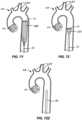
- Figs. 7A-7ZZa particular protocol for introducing a prosthetic valve PV into the patient's native aortic valve AV will be described.
- the delivery sheath 42is initially placed over the guidewire structure 46 as just described with reference to Fig. 6 .
- the catheter body 28is then advanced through the inner lumen of the delivery sheath 42 such that the radially constrained filter body 12 approaches the open distal end 52 of the delivery sheath.
- the distal end of the filter body 12will be released from constraint so that the tubular porous mesh 14 will begin to radially expand, as shown in Fig. 7B .
- the delivery sheath 42continues to be proximally retracted, as shown Fig. 7C , so that the tubular porous mesh 14 expands and engages the inner wall of the ascending aorta immediately above the aortic valve AV.
- Fig. 7CAs shown in Fig.
- the delivery sheath 42continues to be proximally withdrawn, allowing the tubular porous mesh 14 to continue to expand and to begin covering the branch vessels BV, with relative full deployment of the upstream cylindrical chamber 26A of the filter body 12 shown in Fig. 7E .
- the self-sealing port structure 20is at its very initial stages of being formed, with further formation being shown in Fig. 7F .
- the conical base 56 of what will become the self-sealing port 20is largely formed, and the downstream cylindrical chamber 26B begins to form as shown in Fig. 7H .
- the downstream cylindrical chamber 26Bis largely formed as shown in Fig. 7I while the self-sealing port 20 is just beginning to form.
- a narrowed segment of the tubular porous mesh 14will begin to invert to form the sleeve structure 58 of the port 20.
- Fig. 7Gthe conical base 56 of what will become the self-sealing port 20 is largely formed, and the downstream cylindrical chamber 26B begins to form as shown in Fig. 7H .
- the downstream cylindrical chamber 26Bis largely formed as shown in Fig. 7I while the self-sealing port 20 is just beginning to form.
- the radially collapsible support 24in the form of the loop 37, opens to open and support the open distal end of the downstream cylindrical chamber 26. It is this support structure 24 which allows the catheter body 28 to manipulate the downstream portion of the filter body 12 so that the downstream cylindrical chamber 26B can be advanced distally or toward the aortic valve AV relative to the upstream cylindrical chamber 26A.
- the radially expandable/collapsible support 24Awill also be useful when retracting the filter body 12 at the end of the procedure, as will be described in more detail below.
- the fully deployed self-sealing port 20is shown in Fig. 7K with the sleeve 58 defining the expandable opening 22 and the conical base 58 facilitating introduction of catheters from the downstream end, as shown in more detail below.
- the guidewire structure 46may include an external support tube which may be retracted and withdrawn to leave the guidewire in place, as shown in Fig. 7L .
- a diagnostic catheter 60may then be advanced over the guidewire 46, as shown in Fig. 7M typically being used for angiography. This port 20 will expand to accommodate the diameter of the diagnostic catheter 60 while sealing around the catheter to prevent any emboli from passing through the port.
- another guidewire 62may be introduced for advancing a TAVR delivery catheter 64, as shown in Fig. 7N .
- the first catheter structure 46will typically be left in place although it is not visible in Fig. 7N .
- the TAVR delivery catheter 64is then advanced over the patient's aortic arch AA, as shown in Fig. 7O , until it passes through the native aortic valve AV, as shown in Fig. 7P .
- a prosthetic valve PVwill then be released from the TAVR catheter 64, as shown in Fig. 7Q .
- the TAVR delivery catheter 64will be proximally retracted over the guidewire 62, as shown in Fig. 7R .
- the first guidewire 46is also shown in Fig. 7R .
- the TAVR delivery catheter 64continues to be withdrawn and exits through the self-sealing port 20 which then closes over the guidewire 46, as shown in Fig. 7S and 7T .
- the TAVR guidewire 62is then pulled back through the aorta, as shown in Fig. 7T .
- the prosthetic valve PVis in place and it is necessary to withdraw the filter body 12 from the aortic arch AA.
- the tether structure 32is manipulated to close the loop 37 of the radially collapsible support 24.
- the proximal end of the filter structure 12is drawn to the distal end of the catheter body 28, and the catheter body 28 retracted to draw the filter body into the delivery sheath 42, as shown in Fig. 7W .
- the catheter body 28continues to be proximally withdrawn so that it pulls the downstream cylindrical chamber 26 into the delivery sheath 42, as shown in Fig. 7X , and continues to be proximally withdrawn until the entire filter body 12 is drawn into the delivery sheath 42, as shown in Figs. 7Y, 7Z, and 7ZZ .
- the filter body and all emboli contained thereinare then safely captured within the delivery sheath 42, and the delivery sheath 42 may be withdrawn from the patient and the procedure may be completed in a conventional manner.
- the porous filter mesh materialmay comprise a variety of knitted, woven or nonwoven fibers, filaments or wires, and will have a pore size chosen to allow blood to pass through but prevent emboli above a certain size from passing through.
- Suitable materialsinclude resilient metals, such as shape and heat memory alloys, polymers, and combinations thereof, and the materials may optionally have an anti-thrombogenic coating (such as heparin) on their surfaces.
- the filter meshesmay further incorporate materials and structures to enhance the radiopacity of the filter body. Exemplary materials include gold, platinum, palladium, or tantalum, and other metals having a greater radiopacity than the resilient metals, as well as radiopaque coatings or fillings. In other cases, the resilient metal filaments or wires may be served with thinner, more radiopaque wires or filaments.
- the filter bodymaybe constructed in discrete sections that are attached together, but will more typically be formed from a continuous cylindrical mesh structure that is narrowed or folded in sections to form the specific design features, typically consisting of a single such folded tubular mesh structure. Forming the device from one continuous cylindrical mesh allows the filter body to be axially stretched for deployment and/or retrieval, thereby reducing the profile of the filter.
- Another advantage of a filter formed from a single, continuous tabulate mesh materialis that it will contain only smooth, rounded edges. Such edges minimize friction and snagging with catheters and the procedural tools being introduced through the filters.
- the self-sealing portmay be configured as a conical structure with the access port at its narrow end, typically formed by a sleeve as described previously.
- the self-sealing portmay be a simple narrowing of the cylindrical structure, e.g. a self-closing neck region which seal around catheters and other tools introduced therethrough.
- the self-sealing portcan be formed by shape-setting a larger, tubular or cylindrical mesh in a reduced diameter via heat treatment or cold forming.
- the filter bodymay contain two or more such self-expanding port structures.
- the port 20may accommodate a single device (such as a guidewire, catheter, valve delivery system, pacing lead, etc.), two devices or more than two devices simultaneously and can expand and contract to maintain a sufficient seal around multiple devices as needed. Further, such devices can be introduced through the downstream cylindrical chamber 26B and into the port 20 by way of the working lumen 40 of the catheter body 28 or directly by way of a second sheath 50 in an alternative access site, or in some combination thereof.
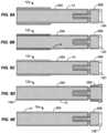
- FIGs 8A-8Ea number of different patterns for forming the tubular porous mesh material 14 of the present invention into a filter body 12 having the self-sealing port 20 between the upstream cylindrical chamber 26A and the downstream cylindrical chamber 26B are illustrated.
- each of the structures in Figs. 8A-8Bbegins with a single layer tube of a mesh material as just described.
- the tubular structureis first folded into a bi-layer structure having a fold 14A in its middle.
- the bi-layer structureis then folded back upon itself and inverted in order to form the illustrated filter body 12a having a structure which is then heat set in the fully radially expanded configuration.
- the filter body 12b of Fig. 8Bsimilarly begins as a bi-layer tubular mesh with a single fold 14B at one end.
- the bi-layer structureis then folded similarly to the pattern of Fig. 8B , except that the open end of cylindrical chamber 26A is folded in an inwardly inverted pattern rather than in a simple fold-back pattern as shown in Fig. 8A .
- the filter body 12c illustrated in Fig. 8Cis again similar in most respects to the fold pattern of filter 12a of Fig. 8A , except that the open end of the upstream cylindrical chamber 26A has an inner layer folded over an outer layer to form a distal cuff, where the inner layer terminates within the folded-back outer layer.
- the filter body 12d illustrated in Fig. 8Dis in many ways the inverse of that filter body 12a of Fig. 8A .
- a single fold 14D in the original single-layer tubular cylinderis located at the open end of the upstream cylindrical chamber 26A.
- the open downstream end of downstream chamber 26Bis folded back on itself to form a cuff structure.
- Filter body 12e as illustrated in Fig. 8Eis the simplest structure of all where folding of the downstream cylindrical chamber 26B is similar to that in Figs. 8A-8C , but the open end of the upstream cylindrical chamber 26A terminates with the inner and outer layers open and not folded back at all.
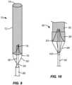
- FIG. 9illustrates a first alternative embodiment of an embolic protection device 70 constructed in accordance with the principles of the present invention.
- a filter body 72has an open upstream end 74 and a closed downstream end 76.
- a self-sealing port 78is formed in the closed downstream end 76, and a support structure 82 is attached at a downstream end of the filter body.
- the support structure 82comprises a pair of struts and can be made of a material (such as a shape memory alloy) that can be compressed for delivery and expanded in situ by the release of a constraining sheath 86.
- the supportis fixedly or movably attached to a deployment catheter body 80 via a collar 84.
- a distal or upstream end of the catheter body 80passes through the closed end 76 of the filter body 72 adjacent to the self-sealing port 78.
- Fig. 10illustrates a second alternative embodiment of an embolic protection device 90 constructed in accordance with the principles of the present invention.
- a filter body 92 with a closed downstream end 93is attached to a deployment catheter body by fully circumferential support structure 96.
- the support structure 96comprises "stent-like" diamond elements over the region where the support structured overlaps and is attached to the mesh material of the filter 92.
- the support structure 96is fixedly or movably attached to a deployment catheter body 94 via a collar 100 and a plurality of struts 98.
- a distal or upstream end of the catheter body 94passes through the closed end 93 of the filter body 92 adjacent to a self-sealing port 99.
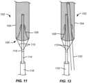
- Figs. 11 and 12illustrate a third alternate embodiment of an embolic protection device 102 having a conical mesh self-sealing port 108 in a closed end 106 of a filter body 104.
- a deployment catheter body 114is attached by a collar 116.
- a delivery sheath 118is provided for delivery and traction of the filter body 104.
- a distal or upstream end of the catheter body 114is disposed through the self-sealing port 108 and provides an introductory lumen or other path through the port adjacent to the self-sealing port 108.
- a TAVR delivery or other working catheteris introduced through the self-sealing port in parallel to the catheter body 114.
- the periphery of the self-sealing port 108will be sufficiently compliant (elastic) to conform to and seal against both catheters simultaneously.
- Figs. 13A-13Cillustrate a fourth alternative embodiment of an embolic protection device 130 constructed in accordance with the principles of the present invention.
- a filter body 132comprises a double layer of mesh throughout most of the filter, with an additional layer or cuff 150 (for a total of three layers) at a downstream end to increase the anchoring strength of the filter in this portion of the device.
- Fig. 13Ashows the embolic protection device 130 in its relaxed configuration
- Figs. 13B and 13Cshow the embolic protection device 130 as it is axially stretched in the direction of arrows 146 into a delivery or retrieval configuration.
- a self-sealing port 134 and other device featuresare integrally or monolithically formed within a continuous cylindrical mesh structure, these features effectively disappear when the filter body 132 is fully stretched out in the axial direction. This ability to stretch out and eliminate internal structure minimizes the device profile.
- the construction of the filter from one continuous cylindrical surfacealso avoids manufacturing complexity and maintains a smooth contact surface throughout the device to reduce the friction of procedural tools passing through the filter.
- the filter bodyis attached to a deployment catheter body 144 by a stent-like peripheral support structure 140 which overlaps or overlies a downstream cylindrical chamber 139 of the filter body 132.
- the self-sealing port 134may comprise a conical base 136 and a sleeve 138 generally as described previously.
- Fig. 14illustrates the embolic protection device 130 deployed over a patient's aortic arch to protect the branch vessels as an interventional catheter is delivered in an upstream direction through the self-sealing port 134 to perform a procedure, such as valvuloplasty or TAVR, at the aortic valve AV.
- a proceduresuch as valvuloplasty or TAVR
- Figs. 15A-15Cshows alternative configurations of the filter body of the present invention.
- Fig. 15Ashows a filter body 160 comprising an upstream cylindrical chamber 162 and a downstream cylindrical chamber 164 separated by a simple narrowing or neck 166 formed in the cylindrical mesh material.
- the cylindrical mesh materialmay be single-walled, double-walled, have more than two layers over some or all of the wall area, or combinations thereof, and this filter body configuration can be combined in most or all of the embodiments of the embolic protection devices of the present invention described previously.
- Fig. 15Bshows a filter body 170 comprising an upstream cylindrical chamber 172, a central cylindrical chamber 174, and a downstream cylindrical chamber 178 separated by a necks 180 and 182, respectively. It will be appreciated that such multiple cylindrical chambers could be separated by any of the self-closing port structures described previously.
- the downstream end of the downstream cylindrical chamber 178may be gathered or closed, as illustrated, and the filter body 170 with a closed downstream end may find particular use in the clot capture configurations described in Figs. 16A-16E below.
- the cylindrical mesh material of filter body 170may be single-walled, double-walled, have more than two layers, or be combinations thereof, and multi-chamber filter body configurations can be combined in most or all of the embodiments of the embolic protection devices of the present invention described previously, although the downstream end of the downstream chamber will have to be opened.
- Fig. 15Cshows a filter body 200 comprising an upstream cylindrical chamber 202, a central cylindrical chamber 204, and a downstream cylindrical chamber 206 separated by a neck 208 and a self-sealing port 210, respectively.
- the downstream end of the downstream cylindrical chamber 206is open, and the multi-chamber filter body 200 can be combined in most or all of the embodiments of the embolic protection devices of the present invention described previously.
- the cylindrical mesh material of filter body 200may be single-walled, double-walled, have more than two layers, or be combinations thereof.
- Figs. 16A-16Eshow a specific procedural using the filter body 170 of Fig. 15B for capturing clot and/or thrombus in a cardiac, peripheral, or cerebral blood vessel BV. Such devices and protocols will be particularly useful for clot/thrombus retrieval in a cranial vessel to treat acute ischemic stroke.
- the gathered end 179 of the filter body 170is attached to a distal end of a deployment catheter 210, and the catheter 210 is advanced through a microcatheter 230 ( Fig. 16E ).
- a clot capture catheter 220such as a Merci ® retriever catheter, having a clot capture element 222, such as a helical tip at its distal end is advanced through the catheter 220, the filter body 170, and into the clot/thrombus THR, as shown in Fig. 16B .
- the clot capture catheter 220is then pulled proximally to draw the clot/thrombus THR through neck 180 into the central chamber 174, as shown in Figs.16B-16D .
- the upstream neck 180will be configured to stretch open to allow the clot retrieval device and the ensnared thrombus and clot to pass through, and to close after the clot and/or thrombus are fully enclosed within the central cylindrical chamber 174. Any debris that may come loose from the clot and thrombus is contained by the fully-closed necks 180 and 182 ( Fig. 16D ), the assembly of the clot retriever 220, the filter body 170, and catheter body 220 may be safely withdrawn through the microcatheter 230.
- Examples of the disclosureinclude the following examples:
Landscapes
- Health & Medical Sciences (AREA)
- Life Sciences & Earth Sciences (AREA)
- General Health & Medical Sciences (AREA)
- Animal Behavior & Ethology (AREA)
- Engineering & Computer Science (AREA)
- Biomedical Technology (AREA)
- Heart & Thoracic Surgery (AREA)
- Veterinary Medicine (AREA)
- Public Health (AREA)
- Vascular Medicine (AREA)
- Cardiology (AREA)
- Oral & Maxillofacial Surgery (AREA)
- Transplantation (AREA)
- Surgery (AREA)
- Nuclear Medicine, Radiotherapy & Molecular Imaging (AREA)
- Medical Informatics (AREA)
- Molecular Biology (AREA)
- Orthopedic Medicine & Surgery (AREA)
- Pathology (AREA)
- Surgical Instruments (AREA)
- Prostheses (AREA)
Abstract
Description
- This application claims the benefit of
U.S. Provisional Application Nos. 62/272,643 (Attorney Docket No. 41959-711.101), filed December 29, 2015 62/294,018 (Attorney Docket No. 41959-711.102), filed February 11, 2016 62/297,053 (Attorney Docket No. 41959-712.101), filed February 18, 2016 U.S. Patent Application No. 15/137,924 (Attorney Docket No. 41959-712.201), filed April 25, 2016 - The disclosure of this application is also related to the disclosures of commonly owned, co-pending
U.S. Patent Application Nos. 14/537,814 (Attorney Docket No. 41959-707.201), filed November 10, 2014 U.S. Patent Application No. 13/735,864 (Attorney Docket No. 41959-705.201), filed January 7, 2013 - 1.Field of the Invention. The present invention relates generally to medical devices and methods and more particularly to apparatus and methods for providing embolic protection to a patient's aortic arch vessels during cardiac surgery and interventional cardiology procedures.
- Cerebral embolism is a known complication of cardiac surgery, cardiopulmonary bypass, and catheter-based interventional cardiology and electrophysiology procedures. Embolic particles, including thrombus, atheroma, and lipids, may become dislodged by surgical or catheter manipulations, enter the bloodstream, and "embolize" to the brain or other vital organs downstream. Cerebral embolism can lead to neuropsychological deficits, stroke, and even death. Other organs downstream of an embolic release can also be damaged, resulting in diminished function or organ failure.
- Of particular interest to the present invention, a number of procedures are performed on aortic valves using catheters advanced over the patient's aortic arch. Valvuloplasty procedures have been performed for many years and use high pressure balloons advanced over the aortic arch to disrupt calcifications on the aortic valve. Such procedures present a significant risk of emboli release to the cerebral arteries. More recently, percutaneous aortic valve replacement (PAVR) procedures, also known as transcatheter aortic valve implantation (TAVI) procedures or transcatheter aortic valve replacement (TAVR) procedures, have been approved, and their use has become widespread. While offering many patient benefits, they also present a significant risk of emboli release, particularly when performed transvascularly with catheters introduced over the aortic arch.
- The prevention of embolism in these and other procedures would benefit patients and improve the outcome of many surgical procedures. Given that potential emboli are often dislodged during catheter-based procedures that involve more than one access site and more than one procedural device, it would be advantageous to deploy an embolic protection system that provides multiple access paths through or beyond the protection device to perform diagnostic and interventional procedures with multiple catheters. It would be further advantageous to integrate the embolic protection system on a sheath that is being used to perform the procedure, such as is used with an angiographic diagnostic catheter, a transcatheter valve delivery system, and an electrophysiology catheter.
U.S. Patent Publ. No. 2015/0066075 , commonly assigned herewith, describes an introducer sheath, intended specifically for use in valvuloplasty and TAVR procedure, which addresses some of the shortcomings of prior embolic protection sheath access devices. The '075 sheath includes embolic protection elements and is suitable for advancing a contrast or other small catheter through the sheath and a second catheter through port formed in a filter. While a significant improvement over previous embolic protection access sheathes having features, particular designs of the '075 access can be challenging to deploy and retrieve, can lose small amounts of emboli, and can have a relatively large profile during deployment.- Therefore, it would be desirable to provide improved devices, systems, and methods for preventing embolism during cardiac and other procedures performed over the aortic arch. Such devices, systems, and methods should offer less complicated deployment protocols, should have a relatively low profile when being deployed, and should afford reliable and efficient emboli containment at all times during a procedure. At least some of these objectives will be met by the inventions described herein.
- 2.Description of the Background Art.
U.S. Patent Publ. No. 2015/0066075 has been described above. Other filters and devices for preventing cerebral embolism are described inU.S. Patent Publ. Nos. 2013/0178891 ;2010/0312268 ;2006/0287668 ;2005/0010246 ;2005/0283186 ;2004/0215167 ; and2003/0100940 ;PCT Publ. WO/2004/019817 ; andU.S. Patent Nos. 8,114,114 ;7,232,453 ;6,712,834 ;6,537,297 ;6,499,487 ;6,371,935 ;6,361,545 ;6,258,120 ;6,254,563 ;6,245,012 ;6,139,517 ; and5,769,819 . - The present invention provides methods, systems, and devices for collecting emboli and in particular for preventing the release of emboli into the cerebral vasculature during the performance of interventional procedures in a patient's aorta, including aortic valve replacement, aortic valve valvuloplasty, and the like, where there is a risk of emboli being released into the aortic side vessels, including the brachiocephalic artery, the left carotid artery, and the left subclavian artery. The present invention provides embolic protection devices, tubular filter bodies, and systems and methods for placement of the devices and filters through the descending aorta and over the aortic arch to inhibit emboli release into the aortic side branch vessels while allowing simultaneous access to the aortic valve by one, two, three or more interventional and/or diagnostic catheters being introduced from the descending aorta, typically by conventional unilateral or bilateral femoral artery access.
- The embolic protection devices include a filter body and a deployment catheter body connected to the filter body. The filter body typically comprises a tubular porous mesh material and has an open upstream end to allow the entry of blood flow and emboli and an open downstream end to allow entry of at least one working catheter and usually two or more working catheters simultaneously. The deployment catheter body is directly or indirectly coupled to the open downstream end of the filter body, where upstream and downstream refer to the direction of blood flow, e.g. downstream is toward the descending aorta and away from the heart and aortic arch. At least one self-sealing port or passage is provided in an interior of the filter body, and the deployment catheter body typically has at least one lumen to provide at least one access route to an interior of the tubular filter body for introducing a diagnostic, interventional or other working catheter through the self-sealing port. Preferably, one or more additional working catheters may be introduced through the same self-sealing passage simultaneously or sequentially with a first catheter introduced through the sheath. Additional self-sealing or other catheter-access ports could be included to provide other, parallel access routes through the filter body but are not usually necessary as the self-sealing passage will typically have a diameter which is sufficiently expandable to allow the simultaneous passage of two or more catheters while being able to close to block emboli release when no catheter is present. Other axially aligned self-sealing catheter-access ports could also be included to provide additional emboli capture chambers within the filter body.
- In a first specific aspect of the present invention, an embolic protection device comprises a filter body formed from a tubular porous mesh material and having an open upstream end and an open downstream end. A self-sealing port is spaced inwardly from each of the ends, and the self-sealing port includes an expandable opening configured to conform to at least one working catheter passing therethrough. A radially collapsible support is coupled to a periphery of the downstream end of the filter body, and a catheter body having a distal end is coupled to the radially collapsible support, where distal refers to a direction on the device away from the operator, i.e., further away from the portion of the device that is outside the body. Similarly, the term proximal refers to a direction of the device closer to the operator, i.e., nearer to the portion of the device that is outside the body. A delivery sheath has a lumen configured to receive and radially constrain the filter body such that the catheter body may be distally advanced relative to the delivery sheath to release the filter body from constraint and to allow the filter body to radially expand with the support circumscribing the downstream end of the filter body. In this way, the catheter body may be distally advanced and proximally retracted relative to the delivery sheath to move the assembly of the support and filter body out of and into the lumen of the delivery sheath. In particular, when advanced out of the delivery sheath, the support will open to assist in deployment of the downstream end of the filter body and, when retracted back into the delivery sheath, the support will close to collapse the downstream end of the filter body prior to the filter body being drawn into the lumen.
- In particular embodiments, the filter body has an open cylindrical chamber disposed between a downstream end of the port and the downstream end of the filter body. The port may comprise a wall portion up the tubular porous mesh material, where the wall portion folds, inverts, or otherwise deflects radially inwardly as other wall portions expand when released from radial constraint from the delivery sheath. In still other particular embodiments, the wall portion inverts to form a port having a conical opening or base on a downstream side. For example, the inverted wall portion of the tubular porous mesh material may have a resiliently closed sleeve portion extending in an upstream direction from an apex of the conical opening or base which defines the expandable opening of the port.
- In still further particular embodiments, the radially collapsible support may comprise a loop secured around the periphery of the downstream end of the filter body. The loop may be connected to a tether which passes through a deployment lumen in the catheter body. The loop may be configured as a lasso to allow the tether to draw the open end of the filter body closed prior to drawing the filter body into the lumen of the delivery sheath. Alternatively, the radially collapsible support may comprise a scaffold having an open end coupled to the periphery of the downstream end of the filter body and a constricted end coupled to the distal end of the catheter body.
- In still other particular embodiments of the present invention, the catheter body will include a lumen for receiving at least one working catheter so that the working catheter may be advanced through the lumen and into the open downstream end of the filter body and then through the port. The catheter body may further include at least one additional lumen for receiving a tether attached to the radially collapsible support. Additional lumens may also be provided for other purposes.
- In a second specific aspect of the present invention, a luminal emboli capture device comprises a filter body formed from a tubular porous mesh material and having an open upstream end, an open downstream end, and at least a first port spaced inwardly from each of the ends. The port comprises an expandable opening configured to conform to at least one working catheter passing therethrough, and the filter body will have at least an open cylindrical chamber at its downstream end and an open cylindrical chamber at its upstream end, where the port is disposed therebetween. The emboli capture device may further comprise a catheter body having a distal end coupled to the downstream end of the filter body.
- In specific embodiments, the porous mesh material comprises a fabric of knitted, braided, woven, or nonwoven fibers, filaments, or wires having a pore size chosen to prevent emboli over a predetermined size from passing therethrough. In many embodiments, the fabric will be double-walled over at least a portion of the tubular mesh, and the porous mesh material may be made of a resilient metal, a polymer material, a malleable material, a plastically deformable material, a shape-memory material, or combinations thereof. In further specific cases, the porous mesh material may have an anti-thrombogenic coating on its surface, and the pore size will typically be in the range from about 1 mm to about 0.1 mm. An exemplary porous mesh material comprises a double layer braid formed from 288 individual wires, including a combination of 276 Nitinol® (nickel-titanium alloy) wires and 12 tantalum wires, each wire being 0.002 inch in diameter, formed to a final double-layer mesh diameter of between 20 mm and 40 mm.
- In further particular embodiments, the at least first port is formed from or comprises a wall portion of the tubular porous mesh material. The wall portion is formed or shaped, e.g. being thermally shaped and set, so that the port folds or closes radially inwardly as other wall portions expand when released from constraint. The wall portion will typically be pre-shaped to invert to form a port with a conical opening on a downstream side, and, typically, a closed sleeve portion extending in an upstream direction from an apex of the conical opening which defines the expandable opening of the port. In alternative embodiments, the port may be defined by a wall portion of the tubular porous mesh which is constricted, pinched, or otherwise closed radially inwardly but will open in response to the passage of the working catheter(s) therethrough. In a particular embodiment, in additional to the upstream and downstream chambers, the filter body may have one or more open "central" cylindrical chambers between a downstream end of the first or other port and an upstream end of the second or other port.
- In a third specific aspect of the present invention, a clot retrieval system comprises an embolic protection device as just described in combination with a clot retrieval working catheter having a clot capture distal end, where the clot retrieval working catheter is configured to draw retrieved clot in a downstream direction through an open upstream end on the filter body into a central chamber.
- In a fourth specific aspect, the present invention provides a method for advancing a working catheter into and/or over a patient's aortic arch. A cylindrical filter body formed at least partly from a porous mesh is provided. The cylindrical filter body defines a collection chamber for emboli and has an open upstream end, an open downstream end, a self-sealing port spaced inwardly from each of the ends, and a radially collapsible support coupled to a periphery of the downstream end of the filter body. A deployment catheter which carries and constrains the cylindrical filter body is advanced to a downstream side of the aortic arch while the filter body remains in its radially constrained configuration, typically with a previously placed delivery sheath. The cylindrical filter body is radially expanded so that a wall of the porous mesh covers the patient's aortic side or branch vessels and the open upstream end of the filter body faces the patient's heart. Blood flows into an interior of the filter body through the open upstream end, and emboli collect in the collection chamber. As the filter body is deployed, the support radially expands to hold the downstream end of the filter body open, and blood flowing through the porous mesh of the filter body and into the aortic side vessels is substantially emboli free. After the filter body is deployed, a first working catheter can be advanced through the open downstream end of the filter body and through the self-sealing port and toward the heart. Optionally, a second working catheter may be advanced through the open downstream end of the filter body and through the self-sealing port toward the heart, either simultaneously or sequentially with placement of the first working catheter.
- In particular embodiments, a first diagnostic or interventional procedure may be performed with the first working catheter and a second diagnostic or interventional procedure may be performed with the second catheter. It will be appreciated that third, fourth, and additional working catheters may also be introduced and advanced either simultaneously or sequentially with other working catheters.
- The first working catheter is typically introduced through a lumen in the deployment catheter, and the second working catheter may be introduced in parallel to the deployment catheter. In this way, the delivery profile of the deployment catheter can be minimized. In one example, a first working catheter will be used to introduce contrast media to an interventional site while a second working catheter will perform an interventional procedure at that site. More specifically, the interventional procedure may comprise delivery of a prosthetic aortic valve, performance of valvuloplasty, or the like.
- In still further particular embodiments, the deployment catheter is advanced while present in a delivery sheath which radially constrains the cylindrical filter body. Radially expanding the cylindrical filter body may comprise proximally retracting the delivery sheath relative to the deployment catheter. Typically, the radially expanded filter body is retrieved by retracting the deployment catheter to collapse the radially collapsible support to close the open downstream end of the filter and draw the closed downstream end of the filter body into the delivery sheath. More specifically, retracting the deployment catheter to collapse the radially collapsible support may comprise retracting a tether present in the lumen of the deployment catheter to first collapse the radially collapsible support to close the downstream end of the filter body and then to retract the deployment catheter to draw the closed downstream end of the filter body into the delivery sheath.
- In still further embodiments, the filter may contain one or more support structures or wires that provide longitudinal stiffness to the device to prevent compression or movement of the filter during the procedure. Such wires or structures may extend the full length of the device or only for a portion of its length and such wires or structures shall be either fixedly or slidably attached to the access sheath.
Fig. 1 is a partially exploded view of a first embodiment of an embolic protection device constructed in accordance with the principles of the present invention.Fig. 2 is a detailed view of the connection between a filter body and a deployment catheter body of the embolic protection device ofFig. 1 .Fig. 3 is a detailed view shown in partial section of a tether structure which connects a downstream end of the filter body to an upstream or distal end of the catheter body of the embolic protection device ofFig. 1 .Figs. 4 and 5 illustrate use of a peel-away catheter for introducing the filter body of the embolic protection device ofFig. 1 into a port of a delivery sheath for advancement to an aortic arch in accordance with the principles of the methods of the present invention.Fig. 6 illustrates the contralateral positioning of the delivery sheath for placement of the embolic protection device and a separate transcatheter aortic valve replacement (TAVR) catheter as would be used for placement of a prosthetic heart valve using the embolic protection device of the present invention.Figs. 7A-7ZZ illustrate positioning of the embolic protection device of the present invention over a patient's aortic arch and delivery of a prosthetic aortic valve through the embolic protection device in accordance with the methods of the present invention.Figs. 8A-8E illustrate a number of different folding patterns for a tubular porous mesh material in order to form filter bodies useful in the embodiments of the present invention.Fig. 9 illustrates a second embodiment of an embolic protection device constructed in accordance with the principles of the present invention.Fig. 10 illustrates a third embodiment of an embolic protection device constructed in accordance with the principles of the present invention.Fig. 11 illustrates a fourth embodiment of an embolic protection device constructed in accordance with the principles of the present invention.Fig. 12 illustrates use of the device ofFig. 11 for introducing a second working catheter through a self-sealing port of the embolic protection device ofFig. 11 .Figs. 13A-13C illustrate a fifth embodiment of an embolic protection device constructed in accordance with the principles of the present invention, and further show a step wise formation of a self-sealing valve in a filter body of the device.Fig. 14 illustrates placement of a sixth embodiment of an embolic protection device constructed in accordance with the principles of the present invention over a patient's aortic arch.Figs. 15A-15C illustrate different folding patterns which can be used to provide self-sealing ports in the filter bodies of the present invention.Figs. 16A-16E illustrate the use of a filter body similar to that shown inFig. 15B for capturing clot in a second exemplary method of the present invention.- As shown in
Figs. 1-3 , anembolic protection device 10 constructed in accordance with the principles of the present invention comprises afilter body 12 having an openupstream end 16 and an opendownstream end 18. Thefilter body 12 is typically formed from a porous mesh material, more typically a tubular porous mesh material which is preformed to have a self-sealingport 20 with anexpandable opening 22 located between the openupstream end 16 and the opendownstream end 18, typically closer to the open downstream end as illustrated. Specific folding patterns for thefilter body 12 are described below with reference toFigs. 8A-8E , and several exemplary alternative folding patterns are described below in connection withFigs. 15A-15C . - A radially expandable/
collapsible support 24 is secured at the opendownstream end 18 of thefilter body 12, as best seen inFig. 2 . The radiallycollapsible support 24 may comprise a tube 34 (Fig. 3 ) having apull wire 36 with aloop 37 formed at its distal end. Theloop 37 is secured about the periphery of the opendownstream end 18 of thefilter body 12 so that it may act as a "lasso" or a "purse-string" component for opening and closing the opendownstream end 18. In particular, by proximally retracting thepull wire 36 within the tube 34 (to the right inFig. 3 ), theloop 37 may be closed. Conversely, by distally advancing thepull wire 36 relative to thetube 34, theloop 37 may be open. As described in more detail below, by axially advancing and retracting thetether structure 32, thefilter body 12 may be positioned relative to adeployment catheter body 28. - The self-sealing
port 20 of thefilter body 12 divides the filter body into an upstreamcylindrical chamber 26A and a downstreamcylindrical chamber 26B. Each of thechambers port 20 will act to divide the two chambers and, in particular, to prevent passage of emboli which may enter theupstream chamber 26A into or beyond thedownstream chamber 26B. The downstreamcylindrical chamber 26B acts to receive and facilitate introduction of working catheters into and through the self-sealingport 20 in order to perform interventional procedures upstream of thefilter body 12 when the filter body is deployed in the aorta or other blood vessels. - The
deployment catheter body 28 has adistal end 30 and at least afirst lumen 38 for carrying thetether structure 32 and asecond lumen 40 which serves as a working lumen for introducing interventional or working catheters therethrough, such as TAVR catheters for deploying prosthetic aortic valves as will be described in detail below. - A proximal or
control hub 29 is coupled to aproximal end 31 of thedeployment catheter body 28. Aproximal end 33 of thetether structure 32 extends from thecontrol hub 29 and allows a user to manipulate the tether structure, and including both axial retraction and advancement of the tether structure as well as opening and closing of theloop 37. Thecontrol hub 29 also has aport 35 which opens to thesecond lumen 40 in thecatheter body 28 for allowing passage of guide wires, working catheters, and the like. - The
filter body 12 will typically be self-expanding. By "self-expanding," it is meant that the filter body will be resilient and have a normally open or expanded configuration when free from radial and/or axial constraint. By either radially contracting or axially extending the filter body, the diameter or profile of the filter body will be reduced so that it can be intravascularly introduced to a working site in the patient's vasculature, typically over the aortic arch but optionally in other locations as well. Additionally, by radially collapsing and/or axially extending the filter body, the self-sealing port within the filter body will be unfolded and axially extended. - The self-sealing
port 20 will be self-forming, typically having aconical base 56 and an extendingsleeve 58, as shown inFig. 1 . The self-sealingport 20 will have at structure which is formed by folding and inverting the generally tubular structure of the filter body as the radius of the filter body increases and the length of the filter body axially shortens. The necessary fold lines will be pre-formed into the filter body, typically by heat treatment. In exemplary embodiments, the filter body will be formed as a Nitinol® (nickel-titanium alloy) thin wire mesh which will be formed to have the fold lines described in more detail with reference toFigs. 8A-8E below. These pre-formed fold lines will allow the filter body to be axially elongated and radially collapsed to have a low profile during delivery, typically having a delivery diameter below 12 Fr (French), often below 10 Fr. Conversely, the filter body will typically open to an unconstrained width or diameter above 5 mm, often above 15mm more often above 25mm, and typically in the range from 25mm to 40mm. As will be described in more detail below, thefilter body 12 will be introduced in its low profile configuration through adelivery sheath 42 which has been pre-placed in the patient's artery, typically through the femoral artery over the aortic arch. In order to advance the filter body into thedelivery sheath 42, however, it is necessary to temporarily constrain the self-expandingfilter body 12. This may be achieved using a peel-awaysheath 48, as shown inFigs. 4 and 5 . Thefilter body 12 is axially elongated and radially collapsed and drawn into the lumen of the peel-awaysheath 48, as shown inFig. 4 . The peel-away sheath covers thefilter body 12 with thecatheter body 28 extending from a proximal end of the peel-awaysheath 48. The temporary assembly of the peel-away sheath and thecatheter body 28 can be introduced over aguidewire structure 46 which has been pre-placed through adistal port 44 of thedelivery sheath 42, as shown inFig. 4 , with the sheath then being advanced through thedistal port 44, as shown inFig. 5 . Once the distal end of thefilter body 12 has been introduced through theport 44 into the proximal end of thedelivery sheath 42, the peel-away sheath may be removed as the filter body continues to be introduced into thedelivery sheath 42. To facilitate delivery, each of thedelivery sheath 42 and the peel-awaysheath 48 may have ports to allow the introduction of fluids into their lumens. - As shown in
Fig. 6 , thedelivery sheath 42 will be introduced through the patient's groin into a femoral artery and up and over the aortic arch in a conventional manner. Asecond sheath 50, typically for introducing a TAVR or other interventional or working catheter, will be positioned in the contralateral femoral artery for introducing the working catheter up the aorta and over the aortic arch AA in parallel to thedelivery sheath 42. Such positioning will be intended for prosthetic valve placement or other interventional procedures on the patient's P heart H. - Referring now to
Figs. 7A-7ZZ , a particular protocol for introducing a prosthetic valve PV into the patient's native aortic valve AV will be described. As shown inFig. 7A , thedelivery sheath 42 is initially placed over theguidewire structure 46 as just described with reference toFig. 6 . Thecatheter body 28 is then advanced through the inner lumen of thedelivery sheath 42 such that the radially constrainedfilter body 12 approaches the opendistal end 52 of the delivery sheath. - By then holding the
catheter body 28 relatively still or stationary and retracting thedelivery sheath 42 in a proximal direction, i.e., away from the patient's aortic valve AV, the distal end of thefilter body 12 will be released from constraint so that the tubularporous mesh 14 will begin to radially expand, as shown inFig. 7B . Thedelivery sheath 42 continues to be proximally retracted, as shownFig. 7C , so that the tubularporous mesh 14 expands and engages the inner wall of the ascending aorta immediately above the aortic valve AV. As shown inFig. 7D , thedelivery sheath 42 continues to be proximally withdrawn, allowing the tubularporous mesh 14 to continue to expand and to begin covering the branch vessels BV, with relative full deployment of the upstreamcylindrical chamber 26A of thefilter body 12 shown inFig. 7E . As also shown inFig. 7E , the self-sealingport structure 20 is at its very initial stages of being formed, with further formation being shown inFig. 7F . - As shown in
Fig. 7G , theconical base 56 of what will become the self-sealingport 20 is largely formed, and the downstreamcylindrical chamber 26B begins to form as shown inFig. 7H . The downstreamcylindrical chamber 26B is largely formed as shown inFig. 7I while the self-sealingport 20 is just beginning to form. By then advancing thecatheter body 28 in the direction toward the aortic valve AV, as shown inFig. 7J , a narrowed segment of the tubularporous mesh 14 will begin to invert to form thesleeve structure 58 of theport 20. As also apparent inFig. 7I and 7J , the radiallycollapsible support 24, in the form of theloop 37, opens to open and support the open distal end of the downstream cylindrical chamber 26. It is thissupport structure 24 which allows thecatheter body 28 to manipulate the downstream portion of thefilter body 12 so that the downstreamcylindrical chamber 26B can be advanced distally or toward the aortic valve AV relative to the upstreamcylindrical chamber 26A. The radially expandable/collapsible support 24A will also be useful when retracting thefilter body 12 at the end of the procedure, as will be described in more detail below. - The fully deployed self-sealing
port 20 is shown inFig. 7K with thesleeve 58 defining theexpandable opening 22 and theconical base 58 facilitating introduction of catheters from the downstream end, as shown in more detail below. - In specific examples, the
guidewire structure 46 may include an external support tube which may be retracted and withdrawn to leave the guidewire in place, as shown inFig. 7L . Adiagnostic catheter 60 may then be advanced over theguidewire 46, as shown inFig. 7M typically being used for angiography. Thisport 20 will expand to accommodate the diameter of thediagnostic catheter 60 while sealing around the catheter to prevent any emboli from passing through the port. - After withdrawing the
diagnostic catheter 60, anotherguidewire 62 may be introduced for advancing aTAVR delivery catheter 64, as shown inFig. 7N . Thefirst catheter structure 46 will typically be left in place although it is not visible inFig. 7N . TheTAVR delivery catheter 64 is then advanced over the patient's aortic arch AA, as shown inFig. 7O , until it passes through the native aortic valve AV, as shown inFig. 7P . A prosthetic valve PV will then be released from theTAVR catheter 64, as shown inFig. 7Q . It should be appreciated that during the advancement of theTAVR catheter 64 over the aortic arch AA, and in particular during release of the prosthetic valve PV, there is a substantial risk of emboli being released as the aortic arch and the aortic valve AV may be heavily calcified. If such emboli are present, they will be carried over the aortic arch and through openupstream end 16 of thefilter body 12 so that they enter and are contained within the uppercylindrical chamber 26A. In particular, the tubularporous mesh 14 will prevent emboli of any significant size from entering any of the branch vessels BV while allowing blood flow into these vessels. Thesleeve 58 of the self-sealingport 20 will conform to and seal around the exterior of theTAVR delivery catheter 64, thus inhibiting or preventing accidental passage of emboli through the port while it is expanded to permit catheter passage. - After the prosthetic valve PV has been released, as shown in
Fig. 7Q , theTAVR delivery catheter 64 will be proximally retracted over theguidewire 62, as shown inFig. 7R . Thefirst guidewire 46 is also shown inFig. 7R . TheTAVR delivery catheter 64 continues to be withdrawn and exits through the self-sealingport 20 which then closes over theguidewire 46, as shown inFig. 7S and 7T . The TAVR guidewire 62 is then pulled back through the aorta, as shown inFig. 7T . - After the
TAVR catheter 64 and guidewire 62 have been withdrawn, the prosthetic valve PV is in place and it is necessary to withdraw thefilter body 12 from the aortic arch AA. As shown inFig. 7U and 7V , thetether structure 32 is manipulated to close theloop 37 of the radiallycollapsible support 24. In addition to closing theloop 37, the proximal end of thefilter structure 12 is drawn to the distal end of thecatheter body 28, and thecatheter body 28 retracted to draw the filter body into thedelivery sheath 42, as shown inFig. 7W . - The
catheter body 28 continues to be proximally withdrawn so that it pulls the downstream cylindrical chamber 26 into thedelivery sheath 42, as shown inFig. 7X , and continues to be proximally withdrawn until theentire filter body 12 is drawn into thedelivery sheath 42, as shown inFigs. 7Y, 7Z, and 7ZZ . The filter body and all emboli contained therein are then safely captured within thedelivery sheath 42, and thedelivery sheath 42 may be withdrawn from the patient and the procedure may be completed in a conventional manner. - The porous filter mesh material may comprise a variety of knitted, woven or nonwoven fibers, filaments or wires, and will have a pore size chosen to allow blood to pass through but prevent emboli above a certain size from passing through. Suitable materials include resilient metals, such as shape and heat memory alloys, polymers, and combinations thereof, and the materials may optionally have an anti-thrombogenic coating (such as heparin) on their surfaces. The filter meshes may further incorporate materials and structures to enhance the radiopacity of the filter body. Exemplary materials include gold, platinum, palladium, or tantalum, and other metals having a greater radiopacity than the resilient metals, as well as radiopaque coatings or fillings. In other cases, the resilient metal filaments or wires may be served with thinner, more radiopaque wires or filaments.
- The filter body maybe constructed in discrete sections that are attached together, but will more typically be formed from a continuous cylindrical mesh structure that is narrowed or folded in sections to form the specific design features, typically consisting of a single such folded tubular mesh structure. Forming the device from one continuous cylindrical mesh allows the filter body to be axially stretched for deployment and/or retrieval, thereby reducing the profile of the filter. Another advantage of a filter formed from a single, continuous tabulate mesh material is that it will contain only smooth, rounded edges. Such edges minimize friction and snagging with catheters and the procedural tools being introduced through the filters.
- The self-sealing port may be configured as a conical structure with the access port at its narrow end, typically formed by a sleeve as described previously. In other embodiments, as illustrated below, the self-sealing port may be a simple narrowing of the cylindrical structure, e.g. a self-closing neck region which seal around catheters and other tools introduced therethrough. Whatever the particular geometry, the self-sealing port can be formed by shape-setting a larger, tubular or cylindrical mesh in a reduced diameter via heat treatment or cold forming. In addition, other embodiments of the self-sealing port can be straight, contain a twist, be corrugated, have a flattened section, or possess other features that assist in its ability to close around procedural devices sufficiently to inhibit or prevent emboli from passing through when a catherter is in place. In still other embodiments, the filter body may contain two or more such self-expanding port structures.. The
port 20 may accommodate a single device (such as a guidewire, catheter, valve delivery system, pacing lead, etc.), two devices or more than two devices simultaneously and can expand and contract to maintain a sufficient seal around multiple devices as needed. Further, such devices can be introduced through the downstreamcylindrical chamber 26B and into theport 20 by way of the workinglumen 40 of thecatheter body 28 or directly by way of asecond sheath 50 in an alternative access site, or in some combination thereof. - Referring now to
Figs 8A-8E , a number of different patterns for forming the tubularporous mesh material 14 of the present invention into afilter body 12 having the self-sealingport 20 between the upstreamcylindrical chamber 26A and the downstreamcylindrical chamber 26B are illustrated. It will be appreciated that each of the structures inFigs. 8A-8B begins with a single layer tube of a mesh material as just described. In the configuration ofFig. 8A , the tubular structure is first folded into a bi-layer structure having afold 14A in its middle. The bi-layer structure is then folded back upon itself and inverted in order to form the illustratedfilter body 12a having a structure which is then heat set in the fully radially expanded configuration. - The
filter body 12b ofFig. 8B similarly begins as a bi-layer tubular mesh with asingle fold 14B at one end. The bi-layer structure is then folded similarly to the pattern ofFig. 8B , except that the open end ofcylindrical chamber 26A is folded in an inwardly inverted pattern rather than in a simple fold-back pattern as shown inFig. 8A . - The
filter body 12c illustrated inFig. 8C is again similar in most respects to the fold pattern offilter 12a ofFig. 8A , except that the open end of the upstreamcylindrical chamber 26A has an inner layer folded over an outer layer to form a distal cuff, where the inner layer terminates within the folded-back outer layer. - The
filter body 12d illustrated inFig. 8D is in many ways the inverse of thatfilter body 12a ofFig. 8A . Asingle fold 14D in the original single-layer tubular cylinder is located at the open end of the upstreamcylindrical chamber 26A. The open downstream end ofdownstream chamber 26B is folded back on itself to form a cuff structure. Filter body 12e as illustrated inFig. 8E is the simplest structure of all where folding of the downstreamcylindrical chamber 26B is similar to that inFigs. 8A-8C , but the open end of the upstreamcylindrical chamber 26A terminates with the inner and outer layers open and not folded back at all.Fig. 9 illustrates a first alternative embodiment of anembolic protection device 70 constructed in accordance with the principles of the present invention. Afilter body 72 has an openupstream end 74 and a closeddownstream end 76. A self-sealingport 78 is formed in the closeddownstream end 76, and asupport structure 82 is attached at a downstream end of the filter body. Thesupport structure 82 comprises a pair of struts and can be made of a material (such as a shape memory alloy) that can be compressed for delivery and expandedin situ by the release of a constrainingsheath 86. The support is fixedly or movably attached to adeployment catheter body 80 via acollar 84. A distal or upstream end of thecatheter body 80 passes through theclosed end 76 of thefilter body 72 adjacent to the self-sealingport 78.Fig. 10 illustrates a second alternative embodiment of anembolic protection device 90 constructed in accordance with the principles of the present invention. Afilter body 92 with a closeddownstream end 93 is attached to a deployment catheter body by fullycircumferential support structure 96. Thesupport structure 96 comprises "stent-like" diamond elements over the region where the support structured overlaps and is attached to the mesh material of thefilter 92. Thesupport structure 96 is fixedly or movably attached to adeployment catheter body 94 via acollar 100 and a plurality ofstruts 98. A distal or upstream end of thecatheter body 94 passes through theclosed end 93 of thefilter body 92 adjacent to a self-sealing port 99.Figs. 11 and 12 illustrate a third alternate embodiment of anembolic protection device 102 having a conical mesh self-sealingport 108 in aclosed end 106 of afilter body 104. Adeployment catheter body 114 is attached by acollar 116. Adelivery sheath 118 is provided for delivery and traction of thefilter body 104. InFig. 11 , a distal or upstream end of thecatheter body 114 is disposed through the self-sealingport 108 and provides an introductory lumen or other path through the port adjacent to the self-sealingport 108. InFig. 12 , a TAVR delivery or other working catheter is introduced through the self-sealing port in parallel to thecatheter body 114. The periphery of the self-sealingport 108 will be sufficiently compliant (elastic) to conform to and seal against both catheters simultaneously.Figs. 13A-13C illustrate a fourth alternative embodiment of anembolic protection device 130 constructed in accordance with the principles of the present invention. Afilter body 132 comprises a double layer of mesh throughout most of the filter, with an additional layer or cuff 150 (for a total of three layers) at a downstream end to increase the anchoring strength of the filter in this portion of the device.Fig. 13A shows theembolic protection device 130 in its relaxed configuration, whileFigs. 13B and 13C show theembolic protection device 130 as it is axially stretched in the direction ofarrows 146 into a delivery or retrieval configuration. Since a self-sealingport 134 and other device features are integrally or monolithically formed within a continuous cylindrical mesh structure, these features effectively disappear when thefilter body 132 is fully stretched out in the axial direction. This ability to stretch out and eliminate internal structure minimizes the device profile. The construction of the filter from one continuous cylindrical surface also avoids manufacturing complexity and maintains a smooth contact surface throughout the device to reduce the friction of procedural tools passing through the filter. The filter body is attached to adeployment catheter body 144 by a stent-likeperipheral support structure 140 which overlaps or overlies a downstreamcylindrical chamber 139 of thefilter body 132. The self-sealingport 134 may comprise aconical base 136 and asleeve 138 generally as described previously.Fig. 14 illustrates theembolic protection device 130 deployed over a patient's aortic arch to protect the branch vessels as an interventional catheter is delivered in an upstream direction through the self-sealingport 134 to perform a procedure, such as valvuloplasty or TAVR, at the aortic valve AV.Figs. 15A-15C shows alternative configurations of the filter body of the present invention.Fig. 15A shows afilter body 160 comprising an upstreamcylindrical chamber 162 and a downstreamcylindrical chamber 164 separated by a simple narrowing orneck 166 formed in the cylindrical mesh material. The cylindrical mesh material may be single-walled, double-walled, have more than two layers over some or all of the wall area, or combinations thereof, and this filter body configuration can be combined in most or all of the embodiments of the embolic protection devices of the present invention described previously.Fig. 15B shows afilter body 170 comprising an upstreamcylindrical chamber 172, a centralcylindrical chamber 174, and a downstreamcylindrical chamber 178 separated by anecks cylindrical chamber 178 may be gathered or closed, as illustrated, and thefilter body 170 with a closed downstream end may find particular use in the clot capture configurations described inFigs. 16A-16E below. As with previous embodiments, the cylindrical mesh material offilter body 170 may be single-walled, double-walled, have more than two layers, or be combinations thereof, and multi-chamber filter body configurations can be combined in most or all of the embodiments of the embolic protection devices of the present invention described previously, although the downstream end of the downstream chamber will have to be opened.Fig. 15C shows afilter body 200 comprising an upstreamcylindrical chamber 202, a centralcylindrical chamber 204, and a downstreamcylindrical chamber 206 separated by aneck 208 and a self-sealingport 210, respectively. The downstream end of the downstreamcylindrical chamber 206 is open, and themulti-chamber filter body 200 can be combined in most or all of the embodiments of the embolic protection devices of the present invention described previously. The cylindrical mesh material offilter body 200 may be single-walled, double-walled, have more than two layers, or be combinations thereof.Figs. 16A-16E show a specific procedural using thefilter body 170 ofFig. 15B for capturing clot and/or thrombus in a cardiac, peripheral, or cerebral blood vessel BV. Such devices and protocols will be particularly useful for clot/thrombus retrieval in a cranial vessel to treat acute ischemic stroke. As shown inFig. 16A , the gatheredend 179 of thefilter body 170 is attached to a distal end of adeployment catheter 210, and thecatheter 210 is advanced through a microcatheter 230 (Fig. 16E ). Aclot capture catheter 220, such as a Merci® retriever catheter, having aclot capture element 222, such as a helical tip at its distal end is advanced through thecatheter 220, thefilter body 170, and into the clot/thrombus THR, as shown inFig. 16B . Theclot capture catheter 220 is then pulled proximally to draw the clot/thrombus THR throughneck 180 into thecentral chamber 174, as shown inFigs.16B-16D . After the clot/thrombus THR is in thecentral chamber 174, the chance that it will be lost from the filter is greatly reduced, and any emboli which might escape through thenecks cylindrical chambers upstream neck 180 will be configured to stretch open to allow the clot retrieval device and the ensnared thrombus and clot to pass through, and to close after the clot and/or thrombus are fully enclosed within the centralcylindrical chamber 174. Any debris that may come loose from the clot and thrombus is contained by the fully-closednecks 180 and 182 (Fig. 16D ), the assembly of theclot retriever 220, thefilter body 170, andcatheter body 220 may be safely withdrawn through themicrocatheter 230.- Modification of the above-described assemblies and methods for carrying out the invention, combinations between different variations as practicable, and variations of aspects of the invention that are obvious to those of skill in the art are intended to be within the scope of the invention disclosure.
- 1. An embolic protection device, said device comprising:
- a filter body comprising a tubular porous mesh material having an open upstream end, an open downstream end, and a self-sealing port spaced inwardly from each of said ends, said port comprising an expandable opening configured to conform to at least one working catheter passing therethrough;
- a radially collapsible support coupled to a periphery of the downstream end of the filter body;
- a catheter body having a distal end coupled to the radially collapsible support; and
- a delivery sheath having a lumen configured to receive and radially constrain the filter body;
- wherein the catheter body may be distally advanced relative to the delivery sheath to release the filter body from constraint and to allow the filter body to radially expand with the support circumscribing the downstream end of the filter body and wherein the catheter body may be distally retracted relative to the delivery sheath to pull the support and filter body back into the lumen of the delivery sheath such that the support radially collapses the downstream end of the filter body prior to the filter body being drawn into the lumen.
- 2. An embolic protection device as in example 1, wherein the filter body has an open cylindrical chamber between a downstream end of the port and the downstream end of the filter body.
- 3. An embolic protection device as in example 1, wherein the port comprises a wall portion of the tubular porous mesh material which folds or closes radially inwardly as other wall portions expand when released from radial constraint from the delivery sheath.
- 4. An embolic protection device as in example 3, wherein the wall portion inverts to form a port with a conical opening on a downstream side.
- 5. An embolic protection device as in example 4, wherein the inverted wall portion of the tubular porous mesh material has a resiliently closed sleeve portion extending in an upstream direction from an apex of the conical opening which defines the expandable opening of the port.
- 6. An embolic protection device as in example 3, wherein the wall portion of the tubular porous mesh material is radially inwardly collapsed to define the expandable opening of the port.
- 7. An embolic protection device as in example 1, wherein the radially collapsible support comprises a loop secured around the periphery of the downstream end of the filter body.
- 8. An embolic protection device as in example 7, wherein the catheter body has at least one deployment lumen which receives a tether attached to the radially collapsible support loop.
- 9. An embolic protection device as in example 7, wherein the loop is configured as a lasso to allow the tether to draw the open end of the filter body closed prior to drawing the filter body into the lumen of the delivery sheath.
- 10. An embolic protection device as in example 1, wherein the radially collapsible support comprises a scaffold having an open end coupled to the periphery of the downstream end of the filter body and a constricted end coupled to the distal end of the catheter body.
- 11. An embolic protection device as in example 1, wherein the catheter body includes at least a working catheter lumen for advancing a working catheter therethrough, into the open downstream end of the filter body, and through the port.
- 12. An embolic protection device as in example 11, wherein the catheter body further includes at least a deployment lumen which receives a tether attached to the radially collapsible support loop.
- 13. A luminal emboli capture device comprising:
- a filter body comprising a tubular porous mesh material having an open upstream end, an open downstream end, and at least a first port spaced inwardly from each of said ends, said port comprising an expandable opening configured to conform to at least one working catheter passing therethrough, wherein the filter body has a downstream open cylindrical chamber between a downstream end of the first port and the downstream end of the filter body and an upstream open cylindrical chamber between an upstream end of the port and the upstream end of the filter body; and
- a catheter body having a distal end coupled to the downstream end of the filter body.
- 14. A luminal emboli capture device as in example 13, wherein the porous mesh material comprises a fabric of knitted, woven, or nonwoven fibers, filaments, or wires having a pore size chosen to prevent emboli over a predetermined size from passing through.
- 15. A luminal emboli capture device as in example 14, wherein the fabric is double-walled over at least a portion of the tubular porous mesh.
- 16. An embolic protection device as in example 14, wherein the porous mesh material is made of a resilient metal, polymer material, a malleable material, a plastically deformable material, a shape-memory material, or combinations thereof.
- 17. An embolic protection device as in example 14, wherein the porous mesh material has an anti-thrombogenic coating on its surface.
- 18. An embolic protection device as in example 14, wherein porous mesh material has a pore size in the range of about 1 mm to about 0.1 mm.
- 19. A luminal emboli capture device as in example 13, wherein the first port comprises a wall portion of the tubular porous mesh material which folds or closes radially inwardly as other wall portions expand when released from radial constraint.
- 20. An embolic protection device as in example 19, wherein the wall portion inverts to form a port with a conical opening on a downstream side.
- 21. An embolic protection device as in example 20, wherein the inverted wall portion of the tubular porous mesh material has a resiliently closed sleeve portion extending in an upstream direction from an apex of the conical opening which defines the expandable opening of the port.
- 22. An embolic protection device as in example 19, wherein the wall portion of the tubular porous mesh material is constricted radially inwardly to define the expandable opening of the port.
- 23. An embolic protection device as in example 19, wherein the tubular porous mesh material includes at least second port longitudinally spaced-apart from the first port, wherein the second port comprises a wall portion of the tubular porous mesh material which folds or closes radially inwardly as other wall portions expand when released from radial constraint.
- 24. An embolic protection device as in example 23, wherein the filter body has an central open cylindrical chamber between a downstream end of the first port and an upstream end of the second port.
- 25. A clot retrieval system comprising:
- an embolic protection device as in example 24; and
- a clot retrieval working catheter having a clot capture distal end, said catheter being configured to draw retrieved clot in a downstream direction through the open upstream end on the filter body into the central chamber.
- 26. A method for advancing a working catheter over a patient's aortic arch, said method comprising:
- providing a cylindrical filter body formed at least partly from a porous mesh which defines a collection chamber for emboli, the filter body having an open upstream end, an open downstream end, a self-sealing port spaced inwardly from each of said ends, a radially collapsible support coupled to a periphery of the downstream end of the filter body, a radially constrained delivery configuration, and a radially expanded deployed configuration;
- advancing a deployment catheter into the aortic arch, wherein a distal end of the deployment catheter is attached to the support on the cylindrical filter body while the cylindrical filter body remains in its radially constrained configuration to position the filter body over the aortic arch;
- radially expanding the cylindrical filter body so that the porous mesh covers the patient's aortic side vessels, the upstream end of the filter body faces the patient's heart to direct blood flow through the upstream end and emboli into the collection chamber, and the support radially expands to hold the downstream end of the filter body open, wherein blood free from emboli flows through the porous mesh into the aortic side vessels; and
- advancing a first working catheter through the open downstream end of the filter body and through the self-sealing port toward the heart.
- 27. A method as in example 26, further comprising advancing a second working through the open downstream end of the filter body and through the self-sealing port toward the heart.
- 28. A method as in example 27, performing a first diagnostic or interventional procedure with the first working catheter and performing a second diagnostic or interventional procedure with the second catheter.
- 29. A method as in example 28, wherein the first working catheter is introduced through a lumen in the deployment catheter and the second working catheter is introduced in parallel to the deployment catheter.
- 30. A method as in example 28, wherein the first working catheter introduces contrast media to an interventional site and the second working catheter performs an interventional procedure.
- 31. A method as in example 31, wherein the interventional procedure comprises delivery of a prosthetic aortic valve.
- 32. A method as in example 27, wherein the deployment catheter is advanced while present in a delivery sheath which radially constrains the cylindrical filter body, and wherein radially expanding the cylindrical filter body comprises proximally retracting the delivery sheath relative to the deployment catheter.
- 33. A method as in example 32, further comprising retrieving the radially expanded filter body by retracting the deployment catheter to collapse the radially collapsible support to close the open downstream end of the filter body and draw the closed downstream end of the filter body into the delivery sheath.
- 34. A method as in example 33, wherein retracting the deployment catheter to collapse the radially collapsible support comprises retracting a tether present in a lumen of the deployment catheter to first collapse the radially collapsible support to close the open downstream end of the filter body and then retracting the deployment catheter to draw the closed downstream end of the filter body into the delivery sheath.
Claims (15)
- An embolic protection device for placement through the descending aorta and over the aortic arch to inhibit emboli release into the aortic side branch vessels while allowing simultaneous access to the aortic valve by at least one interventional and/or diagnostic catheter being introduced from the descending aorta, comprisinga filter body and a deployment catheter body connected to the filter body,wherein the filter body comprises a tubular porous mesh material and has an open upstream end to allow entry of blood flow and emboli and an open downstream end to allow entry of multiple catheters,wherein at least one passage for said at least one interventional and/or diagnostic catheter is provided in the interior of the filter body,wherein the filter body includes at least one catheter access path parallel to said at least one passage through the filter body, andwherein said filter body has one or more support structures or wires that provide longitudinal stiffness to the device to prevent compression or movement of the filter during a procedure.
- The device of claim 1, wherein said wires or support structures extend over the full length of the device.
- The device of claim 1, wherein said wires or support structures extend only for a portion of its length.
- The device of any one of claims 1 to 3, wherein said wires or support structures are slidably attached to an access sheath.
- The device of any one of claims 1 to 4, wherein said at least one passage is a passage for two or more catheters simultaneously.
- The device of any of claims 1 to 5, further comprising a delivery sheath having a lumen configured to receive and radially constrain the filter body such that the deployment catheter body is distally advanceable relative to the delivery sheath to release the filter body from constraint and to allow the filter body to radially expand.
- The device of claim 6, wherein said filter body is retractable into said delivery sheath for retrieving said filter body.
- The device of any of claims 1 to 7, wherein said porous mesh defines a collection chamber for emboli.
- The device of any of claims 1 to 8, wherein the porous mesh material comprises a fabric of knitted, woven, or nonwoven fibers, filaments, or wires having a pore size chosen to allow blood to pass through but prevent emboli over a predetermined size from passing through.
- The device of any of claims 1 to 9, wherein the porous mesh material is made of a resilient metal, polymer material, a malleable material, a plastically deformable material, a shape-memory material, or combinations thereof.
- The device of any of claims 1 to 10, wherein the porous mesh material has an anti-thrombogenic coating on its surface.
- The device of any of claims 1 to 11, wherein the deployment catheter body is directly or indirectly connected to the open downstream end of the filter body.
- The device of any of claims 1 to 12, wherein said passage is longitudinally spaced apart from the catheter-access path.
- The device of any of claims 1 to 13, wherein said interventional and/or diagnostic catheter is a TAVR catheter.
- The device of any of claims 1 to 14, wherein said device is configured for conventional unilateral or bilateral femoral artery access.
Applications Claiming Priority (6)
| Application Number | Priority Date | Filing Date | Title |
|---|---|---|---|
| US201562272643P | 2015-12-29 | 2015-12-29 | |
| US201662294018P | 2016-02-11 | 2016-02-11 | |
| US201662297053P | 2016-02-18 | 2016-02-18 | |
| US15/137,924US10617509B2 (en) | 2015-12-29 | 2016-04-25 | Multi-access intraprocedural embolic protection device |
| PCT/US2016/067686WO2017116828A1 (en) | 2015-12-29 | 2016-12-20 | Multi-access intraprocedural embolic protection device |
| EP16882367.2AEP3397178B8 (en) | 2015-12-29 | 2016-12-20 | Multi-access intraprocedural embolic protection device |
Related Parent Applications (2)
| Application Number | Title | Priority Date | Filing Date |
|---|---|---|---|
| EP16882367.2ADivisionEP3397178B8 (en) | 2015-12-29 | 2016-12-20 | Multi-access intraprocedural embolic protection device |
| EP16882367.2ADivision-IntoEP3397178B8 (en) | 2015-12-29 | 2016-12-20 | Multi-access intraprocedural embolic protection device |
Publications (2)
| Publication Number | Publication Date |
|---|---|
| EP4491157A2true EP4491157A2 (en) | 2025-01-15 |
| EP4491157A3 EP4491157A3 (en) | 2025-03-26 |
Family
ID=59087545
Family Applications (3)
| Application Number | Title | Priority Date | Filing Date |
|---|---|---|---|
| EP24209719.4APendingEP4491157A3 (en) | 2015-12-29 | 2016-12-20 | Multi-access intraprocedural embolic protection device |
| EP16882367.2AActiveEP3397178B8 (en) | 2015-12-29 | 2016-12-20 | Multi-access intraprocedural embolic protection device |
| EP25157249.1APendingEP4566573A3 (en) | 2015-12-29 | 2016-12-20 | Multi-access intraprocedural embolic protection device |
Family Applications After (2)
| Application Number | Title | Priority Date | Filing Date |
|---|---|---|---|
| EP16882367.2AActiveEP3397178B8 (en) | 2015-12-29 | 2016-12-20 | Multi-access intraprocedural embolic protection device |
| EP25157249.1APendingEP4566573A3 (en) | 2015-12-29 | 2016-12-20 | Multi-access intraprocedural embolic protection device |
Country Status (7)
| Country | Link |
|---|---|
| US (5) | US10617509B2 (en) |
| EP (3) | EP4491157A3 (en) |
| JP (1) | JP6854821B2 (en) |
| KR (1) | KR102732643B1 (en) |
| CN (2) | CN108738303B (en) |
| DE (1) | DE202016009224U1 (en) |
| WO (1) | WO2017116828A1 (en) |
Families Citing this family (65)
| Publication number | Priority date | Publication date | Assignee | Title |
|---|---|---|---|---|
| RU2014129392A (en) | 2012-01-06 | 2016-02-27 | Эмболайн, Инк. | Embedded anti-embolic protection |
| EP3373818B1 (en) | 2015-11-09 | 2024-03-06 | Radiaction Ltd. | Radiation shielding apparatuses |
| US10500046B2 (en)* | 2015-12-14 | 2019-12-10 | Medtronic, Inc. | Delivery system having retractable wires as a coupling mechanism and a deployment mechanism for a self-expanding prosthesis |
| US10617509B2 (en) | 2015-12-29 | 2020-04-14 | Emboline, Inc. | Multi-access intraprocedural embolic protection device |
| WO2017147493A1 (en) | 2016-02-24 | 2017-08-31 | Incept, Llc | Enhanced flexibility neurovascular catheter |
| WO2018013515A1 (en)* | 2016-07-12 | 2018-01-18 | Tendyne Holdings, Inc. | Apparatus and methods for trans-septal retrieval of prosthetic heart valves |
| JP7264581B2 (en) | 2017-01-06 | 2023-04-25 | インセプト、リミテッド、ライアビリティ、カンパニー | Antithrombotic coating for aneurysm treatment devices |
| WO2019089821A1 (en)* | 2017-10-31 | 2019-05-09 | Miami Medtech Llc | Embolic protection devices and methods of embolic protection |
| DE102018105671A1 (en)* | 2018-03-12 | 2019-09-12 | Phenox Gmbh | thrombectomy |
| US11684465B2 (en)* | 2018-03-27 | 2023-06-27 | Maduro Discovery, Llc | Accessory device to provide neuroprotection during interventional procedures |
| WO2019195860A2 (en) | 2018-04-04 | 2019-10-10 | Vdyne, Llc | Devices and methods for anchoring transcatheter heart valve |
| US11395665B2 (en) | 2018-05-01 | 2022-07-26 | Incept, Llc | Devices and methods for removing obstructive material, from an intravascular site |
| AU2019262972B2 (en) | 2018-05-01 | 2025-02-27 | Incept, Llc | Devices and methods for removing obstructive material from an intravascular site |
| CN112584799A (en)* | 2018-06-29 | 2021-03-30 | 阿万泰血管公司 | Systems and methods for implants and deployment devices |
| US11471582B2 (en) | 2018-07-06 | 2022-10-18 | Incept, Llc | Vacuum transfer tool for extendable catheter |
| US11517335B2 (en) | 2018-07-06 | 2022-12-06 | Incept, Llc | Sealed neurovascular extendable catheter |
| US10321995B1 (en) | 2018-09-20 | 2019-06-18 | Vdyne, Llc | Orthogonally delivered transcatheter heart valve replacement |
| US11278437B2 (en) | 2018-12-08 | 2022-03-22 | Vdyne, Inc. | Compression capable annular frames for side delivery of transcatheter heart valve replacement |
| US11071627B2 (en) | 2018-10-18 | 2021-07-27 | Vdyne, Inc. | Orthogonally delivered transcatheter heart valve frame for valve in valve prosthesis |
| US12186187B2 (en) | 2018-09-20 | 2025-01-07 | Vdyne, Inc. | Transcatheter deliverable prosthetic heart valves and methods of delivery |
| US10595994B1 (en) | 2018-09-20 | 2020-03-24 | Vdyne, Llc | Side-delivered transcatheter heart valve replacement |
| US11344413B2 (en) | 2018-09-20 | 2022-05-31 | Vdyne, Inc. | Transcatheter deliverable prosthetic heart valves and methods of delivery |
| US11109969B2 (en) | 2018-10-22 | 2021-09-07 | Vdyne, Inc. | Guidewire delivery of transcatheter heart valve |
| WO2020102679A1 (en)* | 2018-11-15 | 2020-05-22 | Baleen Medical Llc | Methods, systems, and devices for embolic protection |
| US11253359B2 (en) | 2018-12-20 | 2022-02-22 | Vdyne, Inc. | Proximal tab for side-delivered transcatheter heart valves and methods of delivery |
| KR102791638B1 (en) | 2019-01-02 | 2025-04-03 | 레디액션 엘티디. | Radiation protection devices and materials therefor |
| EP3905958B1 (en) | 2019-01-02 | 2025-05-21 | Radiaction Ltd. | Patient head protection device |
| WO2020146842A1 (en) | 2019-01-10 | 2020-07-16 | Vdyne, Llc | Anchor hook for side-delivery transcatheter heart valve prosthesis |
| US11185409B2 (en) | 2019-01-26 | 2021-11-30 | Vdyne, Inc. | Collapsible inner flow control component for side-delivered transcatheter heart valve prosthesis |
| US11273032B2 (en) | 2019-01-26 | 2022-03-15 | Vdyne, Inc. | Collapsible inner flow control component for side-deliverable transcatheter heart valve prosthesis |
| KR20210126681A (en) | 2019-02-13 | 2021-10-20 | 엠볼린, 인크. | Catheter with integrated embolic protection |
| WO2020181154A2 (en) | 2019-03-05 | 2020-09-10 | Vdyne, Inc. | Tricuspid regurgitation control devices for orthogonal transcatheter heart valve prosthesis |
| US11173027B2 (en) | 2019-03-14 | 2021-11-16 | Vdyne, Inc. | Side-deliverable transcatheter prosthetic valves and methods for delivering and anchoring the same |
| US11076956B2 (en) | 2019-03-14 | 2021-08-03 | Vdyne, Inc. | Proximal, distal, and anterior anchoring tabs for side-delivered transcatheter mitral valve prosthesis |
| US11766539B2 (en) | 2019-03-29 | 2023-09-26 | Incept, Llc | Enhanced flexibility neurovascular catheter |
| EP3718505A1 (en) | 2019-04-05 | 2020-10-07 | Aorticlab Sarl | Transcatheter anti embolic filter for arterial and venous vessels |
| CN109998749B (en)* | 2019-04-12 | 2021-07-30 | 武汉唯柯医疗科技有限公司 | Intracranial vascular stent with distal protection |
| CA3138875A1 (en) | 2019-05-04 | 2020-11-12 | Vdyne, Inc. | Cinch device and method for deployment of a side-delivered prosthetic heart valve in a native annulus |
| WO2020257125A1 (en) | 2019-06-15 | 2020-12-24 | Maduro Discovery, Llc | Catheter construction |
| CN114340504B (en) | 2019-07-02 | 2025-09-02 | 瑞迪艾森有限公司 | Deployable radiation shield |
| US11707351B2 (en) | 2019-08-19 | 2023-07-25 | Encompass Technologies, Inc. | Embolic protection and access system |
| EP4480458A3 (en) | 2019-08-20 | 2025-04-09 | Vdyne, Inc. | Delivery devices for side-deliverable transcatheter prosthetic valves |
| CN120531525A (en) | 2019-08-26 | 2025-08-26 | 维迪内股份有限公司 | Laterally deliverable transcatheter prosthetic valve and method for its delivery and anchoring |
| US11134859B2 (en) | 2019-10-15 | 2021-10-05 | Imperative Care, Inc. | Systems and methods for multivariate stroke detection |
| EP4076611A4 (en)* | 2019-12-18 | 2023-11-15 | Imperative Care, Inc. | Methods and systems for treating venous thromboembolic disease |
| US20210316127A1 (en) | 2019-12-18 | 2021-10-14 | Imperative Care, Inc. | Hemostasis valve |
| US11638637B2 (en) | 2019-12-18 | 2023-05-02 | Imperative Care, Inc. | Method of removing embolic material with thrombus engagement tool |
| US20230248502A1 (en) | 2019-12-18 | 2023-08-10 | Imperative Care, Inc. | Sterile field clot capture module for use in thrombectomy system |
| US11234813B2 (en) | 2020-01-17 | 2022-02-01 | Vdyne, Inc. | Ventricular stability elements for side-deliverable prosthetic heart valves and methods of delivery |
| CN113747934B (en) | 2020-03-10 | 2024-07-09 | 因普瑞缇夫护理公司 | Enhanced flexibility neurovascular catheter |
| CN111658226B (en)* | 2020-07-21 | 2024-08-09 | 石家庄帝中医疗器械科技有限公司 | Brain protection system and method of use |
| US11207497B1 (en) | 2020-08-11 | 2021-12-28 | Imperative Care, Inc. | Catheter with enhanced tensile strength |
| CN111759531A (en)* | 2020-08-11 | 2020-10-13 | 石家庄帝中医疗器械科技有限公司 | Brain protection device and aortic valve replacement surgical instrument |
| CN112022425A (en)* | 2020-09-11 | 2020-12-04 | 复旦大学附属中山医院 | Thrombus filter device |
| US11786354B2 (en)* | 2020-10-01 | 2023-10-17 | Gil Vardi | Embolic filter device |
| KR20230147061A (en)* | 2021-02-19 | 2023-10-20 | 엠볼린, 인크. | Method and system for placing embolic filters in the aortic arch |
| EP4112004A1 (en)* | 2021-07-01 | 2023-01-04 | Medtronic Inc. | An embolic filter |
| US20230052862A1 (en) | 2021-08-12 | 2023-02-16 | Imperative Care, Inc. | Sterile packaging assembly for robotic interventional device |
| CN113729860A (en)* | 2021-08-16 | 2021-12-03 | 万漉医疗科技(江苏)有限公司 | Thrombus removal device and method |
| USD1077996S1 (en) | 2021-10-18 | 2025-06-03 | Imperative Care, Inc. | Inline fluid filter |
| CN113974712B (en)* | 2021-10-29 | 2024-07-26 | 上海御瓣医疗科技有限公司 | Device for protecting cerebral vessels in cardiovascular surgery |
| CN114788746A (en)* | 2022-05-27 | 2022-07-26 | 首都医科大学附属北京安贞医院 | Far-end filter brain protection device for cardiac surgery |
| CN114767352A (en)* | 2022-05-27 | 2022-07-22 | 首都医科大学附属北京安贞医院 | A support placer for among cardiac surgery art |
| DE112023005161T5 (en)* | 2022-12-13 | 2025-10-02 | Transaortic Medical, Inc. | LOW-PROFILE EMBOLIC PROTECTION DEVICE AND SYSTEM |
| US12171917B1 (en) | 2024-01-08 | 2024-12-24 | Imperative Care, Inc. | Devices for blood capture and reintroduction during aspiration procedure |
Citations (17)
| Publication number | Priority date | Publication date | Assignee | Title |
|---|---|---|---|---|
| US5769819A (en) | 1997-04-24 | 1998-06-23 | Medtronic, Inc. | Catheter distal tip component |
| US6139517A (en) | 1997-12-15 | 2000-10-31 | Cardeon Corporation | Perfusion shunt apparatus and method |
| US6245012B1 (en) | 1999-03-19 | 2001-06-12 | Nmt Medical, Inc. | Free standing filter |
| US6254563B1 (en) | 1997-12-15 | 2001-07-03 | Cardeon Corporation | Perfusion shunt apparatus and method |
| US6258120B1 (en) | 1997-12-23 | 2001-07-10 | Embol-X, Inc. | Implantable cerebral protection device and methods of use |
| US6361545B1 (en) | 1997-09-26 | 2002-03-26 | Cardeon Corporation | Perfusion filter catheter |
| US6371935B1 (en) | 1999-01-22 | 2002-04-16 | Cardeon Corporation | Aortic catheter with flow divider and methods for preventing cerebral embolization |
| US6537297B2 (en) | 1997-05-08 | 2003-03-25 | Embol-X, Inc. | Methods of protecting a patient from embolization during surgery |
| US20030100940A1 (en) | 2001-11-23 | 2003-05-29 | Mindguard Ltd. | Implantable intraluminal protector device and method of using same for stabilizing atheromas |
| WO2004019817A1 (en) | 2002-08-27 | 2004-03-11 | Amir Belson | Embolic protection device |
| US6712834B2 (en) | 1998-06-16 | 2004-03-30 | Mindguard Ltd. | Implantable blood filtering device |
| US20050010246A1 (en) | 2000-06-30 | 2005-01-13 | Streeter Richard B. | Intravascular filter with debris entrapment mechanism |
| US20050283186A1 (en) | 2002-03-12 | 2005-12-22 | Ev3 Inc. | Everted filter device |
| US20060287668A1 (en) | 2005-06-16 | 2006-12-21 | Fawzi Natalie V | Apparatus and methods for intravascular embolic protection |
| US7232453B2 (en) | 2001-12-05 | 2007-06-19 | Sagax, Inc. | Endovascular device for entrapment of particulate matter and method for use |
| US20100312268A1 (en) | 2006-11-29 | 2010-12-09 | Amir Belson | Embolic protection device |
| US20130178891A1 (en) | 2012-01-06 | 2013-07-11 | Emboline, Inc. | Integrated embolic protection devices |
Family Cites Families (144)
| Publication number | Priority date | Publication date | Assignee | Title |
|---|---|---|---|---|
| US4790809A (en) | 1985-08-29 | 1988-12-13 | Medical Engineering Corporation | Ureteral stent |
| US4723549A (en) | 1986-09-18 | 1988-02-09 | Wholey Mark H | Method and apparatus for dilating blood vessels |
| US5108419A (en) | 1990-08-16 | 1992-04-28 | Evi Corporation | Endovascular filter and method for use thereof |
| US5197485A (en) | 1991-10-15 | 1993-03-30 | Pilling Co. | Method and apparatus for sampling aortic plaque |
| US6808520B1 (en) | 1991-12-13 | 2004-10-26 | Endovascular Technologies, Inc. | Dual valve, flexible expandable sheath and method |
| IT1269443B (en) | 1994-01-19 | 1997-04-01 | Stefano Nazari | VASCULAR PROSTHESIS FOR THE REPLACEMENT OR INTERNAL COATING OF MEDIUM AND LARGE DIAMETER BLOOD VESSELS AND DEVICE FOR ITS APPLICATION WITHOUT INTERRUPTION OF BLOOD FLOW |
| ES2340142T3 (en)* | 1994-07-08 | 2010-05-31 | Ev3 Inc. | SYSTEM TO CARRY OUT AN INTRAVASCULAR PROCEDURE. |
| US5643227A (en) | 1995-01-19 | 1997-07-01 | Stevens; Robert C. | Hemostasis cannula valve apparatus and method of using same |
| AU5189496A (en) | 1995-03-30 | 1996-10-16 | Heartport, Inc. | Endovascular cardiac venting catheter and method |
| EP0853668B2 (en) | 1995-09-29 | 2013-03-06 | Vegenics Pty Ltd | Regulated genes and uses thereof |
| US5989281A (en) | 1995-11-07 | 1999-11-23 | Embol-X, Inc. | Cannula with associated filter and methods of use during cardiac surgery |
| US5769816A (en) | 1995-11-07 | 1998-06-23 | Embol-X, Inc. | Cannula with associated filter |
| US5807327A (en) | 1995-12-08 | 1998-09-15 | Ethicon, Inc. | Catheter assembly |
| US5895398A (en) | 1996-02-02 | 1999-04-20 | The Regents Of The University Of California | Method of using a clot capture coil |
| CA2575865C (en)* | 1996-07-17 | 2009-09-22 | C.R. Bard, Inc. | Removable embolus blood clot filter |
| US5662671A (en) | 1996-07-17 | 1997-09-02 | Embol-X, Inc. | Atherectomy device having trapping and excising means for removal of plaque from the aorta and other arteries |
| US5797880A (en) | 1996-09-05 | 1998-08-25 | Becton And Dickinson And Company | Catheter and placement needle assembly with retractable needle |
| US6391044B1 (en) | 1997-02-03 | 2002-05-21 | Angioguard, Inc. | Vascular filter system |
| US6254633B1 (en) | 1997-02-12 | 2001-07-03 | Corvita Corporation | Delivery device for a medical device having a constricted region |
| US5814064A (en) | 1997-03-06 | 1998-09-29 | Scimed Life Systems, Inc. | Distal protection device |
| US5800525A (en) | 1997-06-04 | 1998-09-01 | Vascular Science, Inc. | Blood filter |
| US6340356B1 (en) | 1997-09-23 | 2002-01-22 | NAVIA JOSé ANTONIO | Intraluminal catheter with expandable tubular open-walled element |
| US6120534A (en) | 1997-10-29 | 2000-09-19 | Ruiz; Carlos E. | Endoluminal prosthesis having adjustable constriction |
| US6461370B1 (en) | 1998-11-03 | 2002-10-08 | C. R. Bard, Inc. | Temporary vascular filter guide wire |
| EP1028670B1 (en)* | 1997-11-07 | 2008-01-02 | Salviac Limited | An embolic protection device |
| US6695864B2 (en) | 1997-12-15 | 2004-02-24 | Cardeon Corporation | Method and apparatus for cerebral embolic protection |
| US5928261A (en) | 1998-06-29 | 1999-07-27 | Ruiz; Carlos E. | Removable vascular filter, catheter system and methods of use |
| AU5333599A (en) | 1998-08-06 | 2000-02-28 | Cardeon Corporation | Aortic catheter with porous aortic arch balloon and methods for selective aorticperfusion |
| US6013051A (en) | 1998-10-22 | 2000-01-11 | Medtronic, Inc. | Filtered access port with filter bypass for accessing body fluid samples |
| US6152144A (en) | 1998-11-06 | 2000-11-28 | Appriva Medical, Inc. | Method and device for left atrial appendage occlusion |
| US6083239A (en) | 1998-11-24 | 2000-07-04 | Embol-X, Inc. | Compliant framework and methods of use |
| US7018401B1 (en) | 1999-02-01 | 2006-03-28 | Board Of Regents, The University Of Texas System | Woven intravascular devices and methods for making the same and apparatus for delivery of the same |
| US6355051B1 (en) | 1999-03-04 | 2002-03-12 | Bioguide Consulting, Inc. | Guidewire filter device |
| IL128938A0 (en) | 1999-03-11 | 2000-02-17 | Mind Guard Ltd | Implantable stroke treating device |
| US6267776B1 (en) | 1999-05-03 | 2001-07-31 | O'connell Paul T. | Vena cava filter and method for treating pulmonary embolism |
| GB2365356A (en) | 1999-05-07 | 2002-02-20 | Salviac Ltd | An embolic protection device |
| US7229463B2 (en) | 1999-07-30 | 2007-06-12 | Angioguard, Inc. | Vascular filter system for cardiopulmonary bypass |
| WO2001015629A1 (en) | 1999-08-27 | 2001-03-08 | Microvena Corporation | Slideable vascular filter |
| GB2369575A (en) | 2000-04-20 | 2002-06-05 | Salviac Ltd | An embolic protection system |
| US6520978B1 (en) | 2000-05-15 | 2003-02-18 | Intratherapeutics, Inc. | Emboli filter |
| US6602271B2 (en) | 2000-05-24 | 2003-08-05 | Medtronic Ave, Inc. | Collapsible blood filter with optimal braid geometry |
| US6485501B1 (en) | 2000-08-11 | 2002-11-26 | Cordis Corporation | Vascular filter system with guidewire and capture mechanism |
| US6511496B1 (en)* | 2000-09-12 | 2003-01-28 | Advanced Cardiovascular Systems, Inc. | Embolic protection device for use in interventional procedures |
| US20040098091A1 (en) | 2000-11-17 | 2004-05-20 | Raimund Erbel | Endovascular prosthesis |
| US20020128680A1 (en) | 2001-01-25 | 2002-09-12 | Pavlovic Jennifer L. | Distal protection device with electrospun polymer fiber matrix |
| US7044958B2 (en) | 2001-04-03 | 2006-05-16 | Medtronic Vascular, Inc. | Temporary device for capturing embolic material |
| US6746469B2 (en) | 2001-04-30 | 2004-06-08 | Advanced Cardiovascular Systems, Inc. | Balloon actuated apparatus having multiple embolic filters, and method of use |
| US7201761B2 (en) | 2001-06-29 | 2007-04-10 | Medtronic, Inc. | Method and apparatus for resecting and replacing an aortic valve |
| CN100409818C (en)* | 2001-07-06 | 2008-08-13 | 周星 | Retrievable thrombus temporary filter |
| US20040138692A1 (en) | 2003-01-13 | 2004-07-15 | Scimed Life Systems, Inc. | Embolus extractor |
| US20030144686A1 (en)* | 2002-01-30 | 2003-07-31 | Embol-X, Inc. | Distal filtration devices and methods of use during aortic procedures |
| DE60315425T2 (en) | 2002-03-05 | 2008-06-26 | Salviac Ltd. | SYSTEM FOR PROTECTION FROM EMBOLICS |
| US8070769B2 (en) | 2002-05-06 | 2011-12-06 | Boston Scientific Scimed, Inc. | Inverted embolic protection filter |
| AU2003268379A1 (en) | 2002-09-03 | 2004-03-29 | John R. Fagan | Arterial embolic filter deployed from catheter |
| DE10258708A1 (en) | 2002-12-12 | 2004-07-08 | Simag GmbH Systeme und Instrumente für die Magnetresonanztomographie | vessel filter |
| US7625389B2 (en) | 2002-12-30 | 2009-12-01 | Boston Scientific Scimed, Inc. | Embolic protection device |
| US7235060B2 (en) | 2003-03-27 | 2007-06-26 | Codman & Shurtleff, Inc. | Hydrocephalus shunt system with endoscopic placement features |
| DE602004023350D1 (en) | 2003-04-30 | 2009-11-12 | Medtronic Vascular Inc | Percutaneous inserted provisional valve |
| US7537600B2 (en) | 2003-06-12 | 2009-05-26 | Boston Scientific Scimed, Inc. | Valved embolic protection filter |
| US20050004594A1 (en) | 2003-07-02 | 2005-01-06 | Jeffrey Nool | Devices and methods for aspirating from filters |
| US8337519B2 (en) | 2003-07-10 | 2012-12-25 | Boston Scientific Scimed, Inc. | Embolic protection filtering device |
| JP4712707B2 (en) | 2003-09-12 | 2011-06-29 | ルビコン メディカル インコーポレイテッド | Methods, systems, and instruments for embolic prevention and removal of embolic material. |
| US20050060017A1 (en) | 2003-09-15 | 2005-03-17 | Fischell Robert E. | Means and method for the treatment of cerebral aneurysms |
| US20050075719A1 (en) | 2003-10-06 | 2005-04-07 | Bjarne Bergheim | Minimally invasive valve replacement system |
| US7604650B2 (en) | 2003-10-06 | 2009-10-20 | 3F Therapeutics, Inc. | Method and assembly for distal embolic protection |
| US8840663B2 (en) | 2003-12-23 | 2014-09-23 | Sadra Medical, Inc. | Repositionable heart valve method |
| US20050137696A1 (en) | 2003-12-23 | 2005-06-23 | Sadra Medical | Apparatus and methods for protecting against embolization during endovascular heart valve replacement |
| US7780725B2 (en) | 2004-06-16 | 2010-08-24 | Sadra Medical, Inc. | Everting heart valve |
| US20050159773A1 (en) | 2004-01-20 | 2005-07-21 | Scimed Life Systems, Inc. | Expandable retrieval device with dilator tip |
| US7706179B2 (en)* | 2004-08-04 | 2010-04-27 | The Florida International University Board Of Trustees | Three dimensional magnetic memory and/or recording device |
| US20060100658A1 (en) | 2004-11-09 | 2006-05-11 | Hiroyuki Obana | Interventional guiding sheath system and method of use |
| US20060129181A1 (en) | 2004-12-13 | 2006-06-15 | Callol Joseph R | Retrieval device with retractable dilator tip |
| US7481795B2 (en) | 2004-12-17 | 2009-01-27 | Ethicon Endo-Surgery, Inc. | Circumferential trocar seal assembly |
| US20060173490A1 (en) | 2005-02-01 | 2006-08-03 | Boston Scientific Scimed, Inc. | Filter system and method |
| US7943697B2 (en) | 2005-07-11 | 2011-05-17 | Saint-Gobain Performance Plastics Corporation | Radiation resistant silicone formulations and medical devices formed of same |
| MX2008000491A (en) | 2005-07-19 | 2008-04-17 | Stout Medical Group Lp | Embolic filtering method and apparatus. |
| US8790396B2 (en) | 2005-07-27 | 2014-07-29 | Medtronic 3F Therapeutics, Inc. | Methods and systems for cardiac valve delivery |
| US8021351B2 (en) | 2005-08-18 | 2011-09-20 | Medtronic Vascular, Inc. | Tracking aspiration catheter |
| US20070073332A1 (en) | 2005-09-26 | 2007-03-29 | Medtronic Vascular, Inc. | Intraluminal filter having a cover sleeve |
| US20080234722A1 (en) | 2006-06-14 | 2008-09-25 | Possis Medical, Inc. | Inferior vena cava filter on guidewire |
| EP2043551B1 (en) | 2006-07-19 | 2018-05-09 | Novate Medical Limited | A vascular filter |
| US8460335B2 (en) | 2006-09-11 | 2013-06-11 | Embrella Cardiovascular, Inc. | Method of deflecting emboli from the cerebral circulation |
| US9339367B2 (en) | 2006-09-11 | 2016-05-17 | Edwards Lifesciences Ag | Embolic deflection device |
| JP5604110B2 (en) | 2007-02-05 | 2014-10-08 | ボストン サイエンティフィック リミテッド | System for delivering a valve |
| JP5248606B2 (en) | 2007-06-26 | 2013-07-31 | セント ジュード メディカル インコーポレイテッド | Device for implanting a collapsible / expandable prosthetic heart valve |
| US9034007B2 (en) | 2007-09-21 | 2015-05-19 | Insera Therapeutics, Inc. | Distal embolic protection devices with a variable thickness microguidewire and methods for their use |
| DE102007056946A1 (en) | 2007-11-27 | 2009-05-28 | Gunnar Pah | Device for filtering blood |
| WO2009091509A1 (en) | 2008-01-16 | 2009-07-23 | St. Jude Medical, Inc. | Delivery and retrieval systems for collapsible/expandable prosthetic heart valves |
| AU2009232400B2 (en) | 2008-04-03 | 2013-09-12 | Cook Medical Technologies Llc | Self cleaning devices, systems and methods of use |
| JP5762955B2 (en) | 2008-06-23 | 2015-08-12 | ルーメン・バイオメディカル・インコーポレイテッドLumen Biomedical, Inc. | Embolization prevention during percutaneous heart valve replacement and similar procedures |
| US20100010535A1 (en) | 2008-07-14 | 2010-01-14 | Boston Scientific Scimed, Inc. | Embolic protection device |
| US8052717B2 (en) | 2008-07-14 | 2011-11-08 | Boston Scientific Scimed, Inc. | Embolic protection device |
| DK2537488T3 (en) | 2008-09-04 | 2016-06-27 | Swat Medical Ab | Device for the temporary embolic protection |
| CN102186427B (en)* | 2008-09-22 | 2013-12-18 | 浩特斯博尔技术公司 | flow recovery system |
| US9211202B2 (en) | 2008-10-24 | 2015-12-15 | Wisconsin Alumni Research Foundation | Apparatus and method for treating an aneurysm |
| WO2010078077A1 (en) | 2008-12-30 | 2010-07-08 | Wilson-Cook Medical Inc. | Balloon-tipped endoscopic system |
| US8740930B2 (en) | 2009-02-25 | 2014-06-03 | Medtronic Vascular, Inc. | Embolic filter device independent of treatment device |
| US20100262219A1 (en) | 2009-04-14 | 2010-10-14 | Frimerman Aharon | Device for angioplasty with an embolization protection component and method therefor |
| US8956385B2 (en) | 2009-04-14 | 2015-02-17 | Aharon FRIMERMAN | Integrated distal embolization protection apparatus for endo-luminal devices such as balloon, stent or tavi apparatus |
| US20100274277A1 (en)* | 2009-04-27 | 2010-10-28 | Cook Incorporated | Embolic protection device with maximized flow-through |
| US8298258B2 (en) | 2009-10-05 | 2012-10-30 | Boston Scientific Scimed, Inc | Embolic protection device |
| US8696698B2 (en)* | 2009-12-02 | 2014-04-15 | Surefire Medical, Inc. | Microvalve protection device and method of use for protection against embolization agent reflux |
| US20110152918A1 (en)* | 2009-12-23 | 2011-06-23 | Pavilion Medical Innovations | Reversible Vascular Filter Devices and Methods for Using Same |
| CA2804254C (en) | 2010-02-23 | 2016-11-01 | Medina Medical, Inc. | Devices and methods for vascular recanalization |
| US8420902B2 (en) | 2010-07-30 | 2013-04-16 | Monsanto Technology Llc | Soybean variety A1024640 |
| CN201798779U (en)* | 2010-08-25 | 2011-04-20 | 成正辉 | Thrombus remover |
| ES2683943T3 (en) | 2010-10-22 | 2018-09-28 | Neuravi Limited | Clot capture and removal system |
| GB2485338B (en) | 2010-11-02 | 2012-12-05 | Cook Medical Technologies Llc | Introducer assembly and dilator tip therefor |
| US8808323B2 (en) | 2010-12-21 | 2014-08-19 | BiO2 Medical, Inc. | Configuration and method for fixation of a filter to a catheter |
| US9492264B2 (en) | 2010-12-30 | 2016-11-15 | Claret Medical, Inc. | Embolic protection device for protecting the cerebral vasculature |
| US20120271341A1 (en) | 2011-04-25 | 2012-10-25 | Hill Alexander J | Method and Apparatus for Treating a Mitral Valve Prolapse and Providing Embolic Protection |
| US20120271340A1 (en) | 2011-04-25 | 2012-10-25 | Medtronic, Inc. | Method and Apparatus for Embolic Protection During Heart Procedure |
| DE102011101522A1 (en)* | 2011-05-13 | 2012-11-15 | Phenox Gmbh | thrombectomy |
| US8641777B2 (en) | 2011-06-03 | 2014-02-04 | Reverse Medical Corporation | Embolic implant and method of use |
| US8617200B2 (en)* | 2011-08-17 | 2013-12-31 | Cook Medical Technologies Llc | Multi-layer filtration device |
| US20130096606A1 (en) | 2011-10-17 | 2013-04-18 | William C. Bruchman | Embolic protection devices and related systems and methods |
| WO2013063124A1 (en) | 2011-10-25 | 2013-05-02 | Boston Scientific Scimed, Inc. | Embolic debris deflector |
| US8968354B2 (en) | 2011-10-26 | 2015-03-03 | Boston Scientific Scimed, Inc. | Extended protection embolic filter |
| US9089406B2 (en) | 2012-02-03 | 2015-07-28 | The Cleveland Clinic Foundation | Embolic filter devices, systems, and methods for capturing emboli during medical procedures |
| US20140058372A1 (en) | 2012-08-22 | 2014-02-27 | Amir Belson | Treatment for renal failure |
| CN102973332B (en)* | 2012-11-23 | 2015-01-21 | 杭州启明医疗器械有限公司 | Thrombus filter and using method thereof |
| US20140214069A1 (en) | 2013-01-30 | 2014-07-31 | Edwards Lifesciences Corporation | Inflatable Embolic Deflector |
| US9968433B2 (en)* | 2013-03-01 | 2018-05-15 | St. Jude Medical, Cardiology Division, Inc. | Embolic protection pass through tube |
| RU2017136961A (en) | 2013-03-14 | 2019-02-11 | Вэлв Медикал Лтд. | TRANSMISSION VALVE SYSTEM (OPTIONS) |
| CN105228688B (en) | 2013-03-15 | 2019-02-19 | 伊瑟拉医疗公司 | Vascular treatment devices and methods |
| US8715314B1 (en)* | 2013-03-15 | 2014-05-06 | Insera Therapeutics, Inc. | Vascular treatment measurement methods |
| CN105377157B (en) | 2013-05-29 | 2017-12-08 | 托马斯·A·索斯 | Thrombus removal and intravascular distal embolic protection device |
| US10231751B2 (en)* | 2013-05-29 | 2019-03-19 | Thomas A. Sos | Thrombus removal and intravascular distal embolic protection device |
| US10003637B2 (en)* | 2013-06-27 | 2018-06-19 | Tencent Technology (Shenzhen) Company Limited | Method, mobile terminal and system for displaying picture based on wireless network, and storage medium |
| US20160193045A1 (en) | 2013-08-29 | 2016-07-07 | Mayo Foundation For Medical Education And Research | Self-assembling percutaneously implantable heart valve |
| US10327883B2 (en) | 2013-11-28 | 2019-06-25 | Innovations Ltd. | Filtration and entrapment apparatus and method of use |
| CA3235511A1 (en) | 2014-05-21 | 2015-11-26 | Swat Medical Ab | Improved embolic protection device and method |
| WO2015184450A1 (en) | 2014-05-30 | 2015-12-03 | Cardiac Valve Solutions Llc | Temporary valve and filter on guide catheter |
| FR3021863A1 (en) | 2014-06-05 | 2015-12-11 | Bernard Pain | TRANSCATHETER INTRODUCTION DEVICE IN THE AORTIC ROOT AT THE TUBULAR SINO JUNCTION |
| EP3705087B1 (en) | 2014-09-14 | 2023-12-27 | Emboline, Inc. | Introducer sheath with embolic protection |
| CN104434263A (en)* | 2014-12-01 | 2015-03-25 | 中国人民解放军第二军医大学 | Regulating intracranial intravascular thrombus extraction device |
| DE102015003643B3 (en) | 2015-03-19 | 2016-06-16 | Audi Ag | motor vehicle |
| WO2017074530A1 (en) | 2015-10-26 | 2017-05-04 | Sos Thomas A | Thrombus removal and intravascular distal embolic protection device |
| US10617509B2 (en)* | 2015-12-29 | 2020-04-14 | Emboline, Inc. | Multi-access intraprocedural embolic protection device |
| WO2018026904A1 (en)* | 2016-08-03 | 2018-02-08 | Spence Paul A | Devices, systems and methods to improve placement and prevent heart block with percutaneous aortic valve replacement |
| US20180206970A1 (en) | 2016-11-22 | 2018-07-26 | Boston Scientific Scimed, Inc. | Embolic protection device |
| US11207131B2 (en) | 2017-07-17 | 2021-12-28 | Medtronic, Inc. | Reverse irrigation for embolic mitigation |
| KR20210126681A (en) | 2019-02-13 | 2021-10-20 | 엠볼린, 인크. | Catheter with integrated embolic protection |
| KR20230147061A (en) | 2021-02-19 | 2023-10-20 | 엠볼린, 인크. | Method and system for placing embolic filters in the aortic arch |
- 2016
- 2016-04-25USUS15/137,924patent/US10617509B2/enactiveActive
- 2016-12-20JPJP2018534075Apatent/JP6854821B2/enactiveActive
- 2016-12-20EPEP24209719.4Apatent/EP4491157A3/enactivePending
- 2016-12-20WOPCT/US2016/067686patent/WO2017116828A1/ennot_activeCeased
- 2016-12-20CNCN201680082796.7Apatent/CN108738303B/enactiveActive
- 2016-12-20EPEP16882367.2Apatent/EP3397178B8/enactiveActive
- 2016-12-20EPEP25157249.1Apatent/EP4566573A3/enactivePending
- 2016-12-20CNCN202110915128.0Apatent/CN113662703B/enactiveActive
- 2016-12-20KRKR1020187021515Apatent/KR102732643B1/enactiveActive
- 2016-12-20DEDE202016009224.4Upatent/DE202016009224U1/enactiveActive
- 2020
- 2020-03-04USUS16/808,859patent/US11399927B2/enactiveActive
- 2022
- 2022-07-06USUS17/858,637patent/US12295827B2/enactiveActive
- 2023
- 2023-03-13USUS18/183,067patent/US12263076B2/enactiveActive
- 2023-05-30USUS18/325,163patent/US20230293282A1/enactivePending
Patent Citations (21)
| Publication number | Priority date | Publication date | Assignee | Title |
|---|---|---|---|---|
| US5769819A (en) | 1997-04-24 | 1998-06-23 | Medtronic, Inc. | Catheter distal tip component |
| US6537297B2 (en) | 1997-05-08 | 2003-03-25 | Embol-X, Inc. | Methods of protecting a patient from embolization during surgery |
| US6361545B1 (en) | 1997-09-26 | 2002-03-26 | Cardeon Corporation | Perfusion filter catheter |
| US6139517A (en) | 1997-12-15 | 2000-10-31 | Cardeon Corporation | Perfusion shunt apparatus and method |
| US6254563B1 (en) | 1997-12-15 | 2001-07-03 | Cardeon Corporation | Perfusion shunt apparatus and method |
| US6258120B1 (en) | 1997-12-23 | 2001-07-10 | Embol-X, Inc. | Implantable cerebral protection device and methods of use |
| US6499487B1 (en) | 1997-12-23 | 2002-12-31 | Embol-X, Inc. | Implantable cerebral protection device and methods of use |
| US6712834B2 (en) | 1998-06-16 | 2004-03-30 | Mindguard Ltd. | Implantable blood filtering device |
| US6371935B1 (en) | 1999-01-22 | 2002-04-16 | Cardeon Corporation | Aortic catheter with flow divider and methods for preventing cerebral embolization |
| US6245012B1 (en) | 1999-03-19 | 2001-06-12 | Nmt Medical, Inc. | Free standing filter |
| US20050010246A1 (en) | 2000-06-30 | 2005-01-13 | Streeter Richard B. | Intravascular filter with debris entrapment mechanism |
| US20030100940A1 (en) | 2001-11-23 | 2003-05-29 | Mindguard Ltd. | Implantable intraluminal protector device and method of using same for stabilizing atheromas |
| US7232453B2 (en) | 2001-12-05 | 2007-06-19 | Sagax, Inc. | Endovascular device for entrapment of particulate matter and method for use |
| US20050283186A1 (en) | 2002-03-12 | 2005-12-22 | Ev3 Inc. | Everted filter device |
| WO2004019817A1 (en) | 2002-08-27 | 2004-03-11 | Amir Belson | Embolic protection device |
| US20040215167A1 (en) | 2002-08-27 | 2004-10-28 | Amir Belson | Embolic protection device |
| US8114114B2 (en) | 2002-08-27 | 2012-02-14 | Emboline, Inc. | Embolic protection device |
| US20060287668A1 (en) | 2005-06-16 | 2006-12-21 | Fawzi Natalie V | Apparatus and methods for intravascular embolic protection |
| US20100312268A1 (en) | 2006-11-29 | 2010-12-09 | Amir Belson | Embolic protection device |
| US20130178891A1 (en) | 2012-01-06 | 2013-07-11 | Emboline, Inc. | Integrated embolic protection devices |
| US20150066075A1 (en) | 2012-01-06 | 2015-03-05 | Emboline, Inc. | Introducer sheath with embolic protection |
Also Published As
| Publication number | Publication date |
|---|---|
| US20200197151A1 (en) | 2020-06-25 |
| JP2019501712A (en) | 2019-01-24 |
| KR102732643B1 (en) | 2024-11-20 |
| US12295827B2 (en) | 2025-05-13 |
| DE202016009224U1 (en) | 2024-12-06 |
| KR20180098617A (en) | 2018-09-04 |
| US20230210650A1 (en) | 2023-07-06 |
| US20230091397A1 (en) | 2023-03-23 |
| CN108738303B (en) | 2021-08-20 |
| EP3397178A1 (en) | 2018-11-07 |
| US20230293282A1 (en) | 2023-09-21 |
| EP4566573A2 (en) | 2025-06-11 |
| US20170181835A1 (en) | 2017-06-29 |
| CN108738303A (en) | 2018-11-02 |
| EP4566573A3 (en) | 2025-09-10 |
| EP4491157A3 (en) | 2025-03-26 |
| US10617509B2 (en) | 2020-04-14 |
| EP3397178A4 (en) | 2019-09-04 |
| US11399927B2 (en) | 2022-08-02 |
| CN113662703B (en) | 2024-10-01 |
| CN113662703A (en) | 2021-11-19 |
| WO2017116828A1 (en) | 2017-07-06 |
| EP3397178C0 (en) | 2025-02-12 |
| EP3397178B1 (en) | 2025-02-12 |
| US12263076B2 (en) | 2025-04-01 |
| EP3397178B8 (en) | 2025-03-26 |
| JP6854821B2 (en) | 2021-04-07 |
Similar Documents
| Publication | Publication Date | Title |
|---|---|---|
| US11399927B2 (en) | Multi-access intraprocedural embolic protection device | |
| US12076224B2 (en) | Integrated embolic protection devices | |
| EP3923861B1 (en) | Catheter with integrated embolic protection device | |
| JP6612854B2 (en) | Introducing sheath with embolic protection | |
| EP3975922B1 (en) | Embolic protection catheter | |
| US11351023B2 (en) | Systems and methods for protecting the cerebral vasculature |
Legal Events
| Date | Code | Title | Description |
|---|---|---|---|
| PUAI | Public reference made under article 153(3) epc to a published international application that has entered the european phase | Free format text:ORIGINAL CODE: 0009012 | |
| STAA | Information on the status of an ep patent application or granted ep patent | Free format text:STATUS: REQUEST FOR EXAMINATION WAS MADE | |
| 17P | Request for examination filed | Effective date:20241129 | |
| AC | Divisional application: reference to earlier application | Ref document number:3397178 Country of ref document:EP Kind code of ref document:P | |
| AK | Designated contracting states | Kind code of ref document:A2 Designated state(s):AL AT BE BG CH CY CZ DE DK EE ES FI FR GB GR HR HU IE IS IT LI LT LU LV MC MK MT NL NO PL PT RO RS SE SI SK SM TR | |
| REG | Reference to a national code | Ref country code:DE Ref legal event code:R079 Free format text:PREVIOUS MAIN CLASS: A61F0002240000 Ipc:A61F0002010000 | |
| PUAL | Search report despatched | Free format text:ORIGINAL CODE: 0009013 | |
| AK | Designated contracting states | Kind code of ref document:A3 Designated state(s):AL AT BE BG CH CY CZ DE DK EE ES FI FR GB GR HR HU IE IS IT LI LT LU LV MC MK MT NL NO PL PT RO RS SE SI SK SM TR | |
| RIC1 | Information provided on ipc code assigned before grant | Ipc:A61F 2/24 20060101ALN20250214BHEP Ipc:A61F 2/01 20060101AFI20250214BHEP | |
| STAA | Information on the status of an ep patent application or granted ep patent | Free format text:STATUS: EXAMINATION IS IN PROGRESS | |
| 17Q | First examination report despatched | Effective date:20250403 |