EP4485097A1 - Method for computer-assisted installation of electrical components of a machine arranged in a spatially decentralised manner - Google Patents
Method for computer-assisted installation of electrical components of a machine arranged in a spatially decentralised mannerDownload PDFInfo
- Publication number
- EP4485097A1 EP4485097A1EP23181929.3AEP23181929AEP4485097A1EP 4485097 A1EP4485097 A1EP 4485097A1EP 23181929 AEP23181929 AEP 23181929AEP 4485097 A1EP4485097 A1EP 4485097A1
- Authority
- EP
- European Patent Office
- Prior art keywords
- installation
- component
- identifier
- identification
- machine
- Prior art date
- Legal status (The legal status is an assumption and is not a legal conclusion. Google has not performed a legal analysis and makes no representation as to the accuracy of the status listed.)
- Pending
Links
- 238000009434installationMethods0.000titleclaimsabstractdescription346
- 238000000034methodMethods0.000titleclaimsabstractdescription71
- 230000000977initiatory effectEffects0.000claimsdescription28
- 238000004590computer programMethods0.000claimsdescription19
- 238000010586diagramMethods0.000claimsdescription13
- 238000012545processingMethods0.000claimsdescription9
- 238000012795verificationMethods0.000claimsdescription6
- 230000003190augmentative effectEffects0.000claimsdescription5
- 238000012423maintenanceMethods0.000claimsdescription5
- 238000012800visualizationMethods0.000claimsdescription5
- 230000008859changeEffects0.000claimsdescription4
- 238000004519manufacturing processMethods0.000claimsdescription4
- 238000010147laser engravingMethods0.000claimsdescription3
- 238000012937correctionMethods0.000claimsdescription2
- 238000003860storageMethods0.000description15
- 230000008901benefitEffects0.000description5
- 238000013439planningMethods0.000description5
- 230000008569processEffects0.000description5
- 230000006870functionEffects0.000description4
- 238000002372labellingMethods0.000description4
- 238000012360testing methodMethods0.000description4
- 238000004891communicationMethods0.000description3
- 230000005540biological transmissionEffects0.000description2
- 238000013500data storageMethods0.000description2
- 238000001514detection methodMethods0.000description2
- 230000000694effectsEffects0.000description2
- 238000005516engineering processMethods0.000description2
- 238000011156evaluationMethods0.000description2
- 238000005457optimizationMethods0.000description2
- 108010076504Protein Sorting SignalsProteins0.000description1
- 238000013473artificial intelligenceMethods0.000description1
- 230000000712assemblyEffects0.000description1
- 238000000429assemblyMethods0.000description1
- 230000002457bidirectional effectEffects0.000description1
- 230000001413cellular effectEffects0.000description1
- 238000011161developmentMethods0.000description1
- 238000009826distributionMethods0.000description1
- 238000009429electrical wiringMethods0.000description1
- 230000007613environmental effectEffects0.000description1
- 230000010354integrationEffects0.000description1
- 238000007726management methodMethods0.000description1
- 230000002093peripheral effectEffects0.000description1
- 230000000704physical effectEffects0.000description1
- 230000008439repair processEffects0.000description1
- 230000009897systematic effectEffects0.000description1
- 238000012546transferMethods0.000description1
- 230000001960triggered effectEffects0.000description1
- 238000011144upstream manufacturingMethods0.000description1
- 238000012559user support systemMethods0.000description1
- 238000010200validation analysisMethods0.000description1
Images

Classifications
- G—PHYSICS
- G05—CONTROLLING; REGULATING
- G05B—CONTROL OR REGULATING SYSTEMS IN GENERAL; FUNCTIONAL ELEMENTS OF SUCH SYSTEMS; MONITORING OR TESTING ARRANGEMENTS FOR SUCH SYSTEMS OR ELEMENTS
- G05B19/00—Programme-control systems
- G05B19/02—Programme-control systems electric
- G05B19/04—Programme control other than numerical control, i.e. in sequence controllers or logic controllers
- G05B19/042—Programme control other than numerical control, i.e. in sequence controllers or logic controllers using digital processors
- G05B19/0423—Input/output
- G—PHYSICS
- G05—CONTROLLING; REGULATING
- G05B—CONTROL OR REGULATING SYSTEMS IN GENERAL; FUNCTIONAL ELEMENTS OF SUCH SYSTEMS; MONITORING OR TESTING ARRANGEMENTS FOR SUCH SYSTEMS OR ELEMENTS
- G05B19/00—Programme-control systems
- G05B19/02—Programme-control systems electric
- G05B19/04—Programme control other than numerical control, i.e. in sequence controllers or logic controllers
- G05B19/042—Programme control other than numerical control, i.e. in sequence controllers or logic controllers using digital processors
- G05B19/0426—Programming the control sequence
- G—PHYSICS
- G05—CONTROLLING; REGULATING
- G05B—CONTROL OR REGULATING SYSTEMS IN GENERAL; FUNCTIONAL ELEMENTS OF SUCH SYSTEMS; MONITORING OR TESTING ARRANGEMENTS FOR SUCH SYSTEMS OR ELEMENTS
- G05B2219/00—Program-control systems
- G05B2219/20—Pc systems
- G05B2219/25—Pc structure of the system
- G05B2219/25061—Configuration stored in central database
- G—PHYSICS
- G05—CONTROLLING; REGULATING
- G05B—CONTROL OR REGULATING SYSTEMS IN GENERAL; FUNCTIONAL ELEMENTS OF SUCH SYSTEMS; MONITORING OR TESTING ARRANGEMENTS FOR SUCH SYSTEMS OR ELEMENTS
- G05B2219/00—Program-control systems
- G05B2219/20—Pc systems
- G05B2219/25—Pc structure of the system
- G05B2219/25068—Check correct configuration of device
Definitions
- the present inventionrelates generally to the field of planning and assembly of machines such as automation systems, and in particular to a computer-aided installation of spatially decentralized electrical components of a machine.
- the underlying object of this inventionis in particular to provide a solution which enables a simple, fast, safe and error-free installation of electrical components and at least partially overcomes the above-mentioned disadvantages of the prior art.
- the subject matter of the inventionis a method having the features of claim 1, a system having the features of claim 13, a computer program having the features of claim 14 and a device having the features of claim 15. Further features and details of the invention emerge from the respective subclaims, the description and the drawings. Features and details that are in the connection with the method according to the invention, of course also in connection with the system according to the invention, the computer program according to the invention and the device according to the invention, and vice versa, so that with regard to the disclosure of the individual aspects of the invention, reference is or can always be made to each other.
- the subject matter of the inventionis in particular a preferably computer-implemented method for a computer-aided installation of spatially decentralized electrical components of a machine, in particular an electrical system, preferably an automation system.
- the following steps of the methodcan be provided, which are preferably carried out one after the other and/or repeatedly:
- provisioncan be made of an installation specification, in particular an electrical circuit diagram.
- the installation specificationcan specify an assignment of the respective components to one or more installation locations of the machine.
- the installation specificationcan be provided in digital form, for example, and can be stored non-volatilely in a data storage device and/or a database.
- the electrical circuit diagramcan be created, for example, using software via a graphical user interface.
- the graphical user interfaceenables, for example, a selection and placement of symbolic representations of electrical equipment of the machine, e.g. the components.
- the equipmentcan be connected to one another in order to represent the electrical connections in the circuit diagram.
- data structures and validation rulescan be implemented to ensure the consistency and freedom from errors of the circuit diagram.
- Installation locations for the componentscan be specified in the circuit diagram and, if necessary, specified in a connection plan.
- the connection diagramcan indicate the exact positions and connections of these installation locations to provide a clear and unambiguous representation of the electrical wiring and connections. This allows installers to efficiently and correctly make the connections between the equipment and the corresponding slots.
- the installation locationsinclude, for example, physical slots and/or physical connections and/or local areas of the machine.
- the installation specificationcan specify an installation identifier, in particular equipment identifier, and an article identifier, in particular article number, for one or more installation locations, preferably as a unique identifier. This enables the components to be clearly assigned to the installation locations, which preferably represents the actual installation of the components on the machine.
- the installation marking and preferably the equipment markingrefers in particular to the marking of components or, in general, electrical equipment to provide information about their type and/or identity and/or function and/or properties and/or safety features. These markings can traditionally not only be indicated in the circuit diagram, but can also be applied to the equipment itself in the form of physical identification means such as stickers, signs, labels or markings.
- the installation or equipment markingcan include important information such as the device name and/or serial number and/or voltage range and/or power consumption and/or manufacturer information and/or warnings and/or other relevant information.
- the installation or equipment markingcan be determined when the machine is planned and stored in the circuit diagram. In conventional solutions, the installation or equipment marking is also physically attached manually to the equipment such as the component.
- the receiving of an identifier of a component to be installedcan be provided.
- the identifiercan differ from the installation marking in the installation specification and in particular from the conventionally used installation or equipment markings.
- the identifiercan also be attached to the component via a physical means of identification, e.g. printed on.
- a physical means of identificatione.g. printed on.
- thiscan be done originally and generically for the components, regardless of a specific circuit diagram or a specific installation.
- components such as cablescan originally be provided with a series and/or article marking or a network-capable connection module can originally have a network address.
- the use of a physical means of identificationsuch as a print of this information enables the identifier to be read in easily by machine in order to be able to receive the read identifier in the form of digital data.
- the received identifiercan be assigned to at least one of the installation markings on the basis of the article markings in the installation specification.
- the article markingscan be used to determine which of the installation markings the received identifier can be assigned to.
- the installation markingscan also indicate different installation locations for which the installation markings are specified by the installation specification.
- the assignmentthus enables at least one of the installation locations for the installation of the component to be installed to be determined on the basis of the assignment of the received identifier in a further process step.
- Several of the installation identifierscan also be considered for the assignment and thus also several installation locations, so that the desired installation location or the desired installation identifier can be selected if necessary.
- the inventionnot only makes it possible to dispense with the otherwise usual and time-consuming subsequent attachment of the installation marking to the component, it even allows a dynamic selection of suitable installation locations to be made during installation.
- the received identifiercomprises a component identifier for the component to be installed, wherein the component identifier comprises a series identifier and/or an article identifier and/or a manufacturer identifier and/or network address, wherein preferably the article identifier of the component identifier and/or the article identifiers specified in the installation specification are each designed as generic identifiers of the components.
- the component identifiercan only comprise original and therefore generic identifiers of the component. This can reduce the effort and susceptibility to errors due to the subsequent attachment of such identifiers.
- the assignment of the received identifiermay further comprise: determining the generic suitability of the component to be installed for installation at at least one of the installation locations.
- the component to be installedmay be assigned at least one of the article identifiers specified for the installation locations in the Installation specifications can be assigned to the component identification of the received identifier based on the article identification.
- the article identification of the component identificationis simply compared with the article identifications in the installation specification.
- the article identifications in the installation specificationare also assigned to the installation identifications and thus to the installation locations ("specified for the installation location"), so that a (suitable) installation location for the component can also be determined in this way.
- the specification of the article identifications and installation identifications for the installation locationscan be provided in such a way that the article identifications indicate the suitability of the type specified by the article identifications for installation at these installation locations. Suitability can therefore preferably be determined if the article identifications indicate a match.
- At least one of the installation locations for which the component to be installed is suitable for installationcan be selected. Since the article identifiers only indicate the type suitable for installation and not a specific component, several installation locations for the installation of the component can be considered.
- the component identifier of the received identifiercan be assigned at least partially, in particular at least the series identifier, to the installation identifier specified for the selected installation location. In this way, the component can be specified for installation at the installation location and therefore receive the installation identifier specified for the selected installation location.
- a respective type of componentis specified both by the received identifier and by the article markings in the installation specification, wherein in order to determine the at least one installation location for the component to be installed, it can also be provided: determining a generic suitability of the component to be installed for installation at at least one of the installation locations by comparing the type of component to be installed with the types according to the article markings in the installation specification in order to classify the component to be installed as suitable for installation at at least one of the installation locations.
- the identifiercomprises at least a unique and preferably one-to-one identification for the component to be installed.
- the component to be installedcan still be clearly and preferably one-to-one distinguished from the other components, in particular also from other manufacturers of the components, as with conventional identification.
- This advantage over known solutionsis preferably achieved by providing a combination of a serial identification and manufacturer identification or a network address to identify the component and preferably functionally replacing a component-side installation identification on the component to be installed for the installation.
- the updated installation specificationcan be used in this way for further installation of the machine.
- the updated installation specificationcan also be accessed at least partially automatically if necessary in order to carry out and/or check the physical installation of the machine at least partially automatically, e.g. to check for correctness with respect to the installation specification.
- the serial identificationcan be designed to clearly identify the component and in particular an operating resource and thus distinguish it from other components or operating resources.
- Each of the serial markings usedcan therefore be unique to avoid confusion.
- the serial markingscan be designed as serial numbers with a combination of numbers and/or letters.
- the inventioncan provide that the components are designed as electrical equipment of the machine in the form of an electrical system, which are assigned to different types, wherein the components according to a first type comprise several decentrally arranged connecting elements, in particular cables, and according to a second type comprise several decentrally arranged connecting modules, wherein the connecting modules each comprise several connection points for electrical connection to the connecting elements, to control other devices on the machine, in particular sensors and/or actuators, via the connecting elements.
- connection modulescan be connected decentrally (in relation to a control cabinet that would otherwise be intended for central installation) via the connection modules.
- the received identifiercomprises a component identification for the component to be installed, wherein the component identification can comprise different ones of the following identifications depending on a type of component to be installed: a unique identification, a serial identification, an article identification, a manufacturer identification, network address, preferably a MAC address, a machine-readable code, preferably a QR code.
- the identifierhas a serial identification, in particular a serial number, in order to identify the component to be installed - preferably uniquely - for the manufacturer of the component.
- the serial identificationcan be manufacturer-related and thus ensure unique identification only for the manufacturer.
- the identifiercan have an article identification, preferably article number, in order to identify the type and/or technical properties of the component.
- the article identificationcan also identify the component for the manufacturer - preferably uniquely.
- the article identificationcan also be manufacturer-related and thus ensure unique identification only for the manufacturer of the component.
- the identifiercan have a manufacturer identification that identifies the manufacturer of the component. The combination of article identification and manufacturer identification or series identification and manufacturer identification can also result in unique identification for different manufacturers.
- the installation specificationincludes a predefined specification on a modular and/or decentralized structure of the machine, in particular the electrical system, preferably an electrical and/or mechanical and/or network connection plan.
- the component to be installedis a connecting element, in particular a cable, and/or a connecting module for the decentralized connection of sensors and/or actuators via connecting elements to a control device.
- the received identifier and/or preferably a component identification of the received identifieris an original identification of the component to be installed, wherein preferably the identifier and in particular the component identification at the time of manufacture and/or at the time of has been attached to the component to be installed at the time of assembly, in particular printed and/or applied and/or glued by laser engraving and/or laser labeling, wherein the identifier preferably comprises a code, in particular a bar code or QR code, in order to be recorded for reception by a reading device.
- system according to the inventionthus brings with it the same advantages as have been described in detail with reference to a method according to the invention.
- the systemcan be suitable for carrying out the steps of a method according to the invention.
- the inventionalso relates to a computer program, comprising instructions which, when the computer program is executed by a computer, cause the computer to carry out the steps of a method according to the invention.
- a device for data processingcan be the subject of the invention, comprising means for carrying out the steps of a method according to the invention.
- centralized control cabinet systemssee Fig. 1
- decentralized systemssee Fig. 2
- control modulesare attached directly to the systems.
- the corresponding processesare carried out by different people, such as system planners, electrical planners, installers, system programmers, etc.
- a special feature of decentralized systemsis the distribution of the modules at different points on a machine in comparison to centralized control cabinet systems.
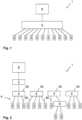
- FIG. 1A central interconnection by means of a control cabinet 9 is shown schematically in order to compare this with a decentralized interconnection by means of spatially decentralized electrical components 4 of a machine 1 in Fig. 2
- the components 4can comprise various types such as connecting elements 60, for example cables, and connecting modules 50.
- connecting elements 60for example cables
- connecting modules 50instead of connecting all devices 5 such as sensors and actuators directly to the control cabinet 9 - as in Fig. 1 shown - can be used in decentralized interconnection in Fig. 2 several components 4, i.e. in particular the connection modules 50, are used to connect the devices 5 in the field.
- the connection modules 50like the control cabinet 9, enable the devices 5 to be coupled to a control device 8 such as a PLC (i.e.
- connection modules 50can be provided in a decentralized manner and distributed in the vicinity of the devices 5.
- a central control cabinet 9is at least partially divided into several decentralized connection modules 50.
- the connection modules 50thus only partially connect the devices 5, whereby the connection modules 50 together or, for example, one and/or several connection modules 50 can carry out the entire connection via one and/or several hubs 6.
- a controller module 3also referred to as master module 3 can be connected upstream of several of the individual connection modules 50.
- the controller module 3can then control the associated Configure connection modules 50.
- the connection modules 50 connected theretocan be regarded as peripheral connection modules 50. It is also possible for the interconnection to be further subdivided using at least one hub 6.
- Fig. 3 1shows parts of a system 2 according to embodiments of the invention.
- the system 2can be provided for computer-aided installation of spatially decentralized electrical components 4 of a machine 1.
- the components 4can thus comprise at least some of the operating resources which are required for the installation and thus for providing the function of the machine 1.
- the components 4can each comprise an identifier 11 which is designed to identify the component 4 at least uniquely and/or according to its type.
- the identifier 11can have a component identifier 200 which can result from a combination or compilation of several individual identifiers such as an article identifier 201 and/or a series identifier 202 and/or a manufacturer identifier 203 and/or a network address 208.
- the component identifier 200can have only one of these identifiers, e.g. B. the network address 208.
- the system 2can be provided with a reader 22 for detecting the identifier 11.
- the reader 22can be designed as a mobile, portable device which a user can use directly on the component 4 such as a cable 60 to detect the identifier 11.
- a device 30can be provided in the system 2 for data processing.
- the device 30, specifically a computer program 20 in a data memory 33 of the device 30,can receive the detected identifier 11 and assign it to at least one installation marking 230 on the basis of generic markings 201 in an installation specification 300 for the computer-aided, decentralized installation of the electrical components 4 in a machine 1.
- the installation specification 300can be designed as an electrical circuit diagram and provided digitally.
- the installation specification 300is stored at least partially in the data memory 33 of the device 30 and/or in an external data memory (e.g. a cloud-based database) in a non-volatile manner.
- the installation specification 300is designed, for example, as a digital electrical circuit diagram 300, which in particular has a (digitized) connection plan.
- Fig. 3the installation specification 300 is shown schematically in such a way that several installation markings 230, in particular each in the form of a device marking, and article markings 201, in particular each in the form of an article number, are assigned to one another and are defined for several installation locations 301.
- the installation locations 301are, for example, the connections of the machine 1 intended for installation and include, for example, the Fig. 3 shown connection points 42 of the connection modules 50.
- the components 4can comprise connection elements 60 such as cables or also the connection modules 50, which, depending on the type, can be connected to one or more of the connections of the machine 1 according to the connection plan.
- the article identification 201can specify the type and the installation identification 230 can be clearly assigned to the installation location 301, i.e., for example, one of the connection points 42.
- a certain component 4can be connected based on its type.
- a specific component 4e.g.
- a specific cable of a certain type and with a certain serial numberdoes not have to be assigned to a certain installation location 301 in the installation specification 300 from the outset - it is sufficient to make this assignment flexibly during installation.
- the assignmentcan be permanently stored in the installation specification 300 in order to document the installation accordingly.
- an automated checkis then carried out to determine whether component 4 has actually been connected to the selected installation location 301.
- the component identification 200 of the connected component 4can be determined and compared with the stored assignment in the installation specification 300.
- a computer program 20according to embodiments of the invention is shown, which comprises instructions which, when the program is executed by a computer 30, cause the computer 30 to carry out the steps of the method 100 according to embodiments of the invention.
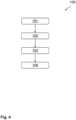
- Fig. 4process steps of the process 100 are visualized.
- the installation specification 300is used for installation because it assigns the components 4 to one or more installation locations 301 of the machine 1.
- the installation specification 300indicates at which installation locations 301 the components 4 are to be installed according to a predefined plan. This assignment can be specified step by step for all components 4 during installation, but can previously only be specified with regard to the required type of components 4 in the installation specification 300. Therefore, the installation specification 300 can specify an installation identifier 230, in particular equipment identifier, and an article identifier, in particular article number, for each of the one or more installation locations 301, preferably as a unique identifier.
- the article identification 201can indicate the required type of component 4 for one of the installation locations 301 and the installation identification 230 can clearly assign the component 4, which is yet to be specified, to this installation location 301 according to the required type.
- the identifier 11 of a component 4 of the components 4 to be installedcan first be received according to a second method step 102 and assigned to at least one of the installation identifiers 230 on the basis of the article identifiers 201 in the installation specification 300 according to a third method step 103. Then, according to a fourth method step 104, at least one of the installation locations 301 for the installation of the component 4 to be installed can be determined on the basis of the assignment 103 of the received identifier 11.
- those installation locations 301 for the installation of the component 4 to be installed and thus as installation locations 301 suitable for the installationcan be determined for which an article identifier 201 is specified in the installation specification 300 that indicates the type of component 4 to be installed.
- the component 4 that is installed at this installation location 301can then be specified.
- the installation at this installation location 301can also be documented, e.g. by storing at least part of the identifier 11 in the installation template 300 assigned to the installation identifier 230 defined for the selected installation location 301.
- the received identifier 11can be used.
- the received identifier 11can comprise a component identifier 200 for the component 4 to be installed, wherein the component identifier 200 preferably comprises a series identifier 202 and/or an article identifier 201 and/or a manufacturer identifier 203 and/or network address 208 (see. Fig. 3 ). This makes it possible to determine whether the component 4 to be installed is suitable for installation at at least one of the installation locations 301.
- the component 4 to be installedcan be assigned to at least one of the article identifiers 201 specified for the installation locations 301 in the installation specification 300 using the article identifier 201 of the component identifier 200 of the received identifier 11, for example by determining which of the article identifiers 201 in the installation specification 300 the article identifier 201 of the component identifier 200 matches.
- the installation locations 301 for which these matching article identifiers 201 are specifiedare determined in this way and can be selected for installation.
- the component identification 200 of the received identifier 11can then be assigned at least partially, in particular at least the serial identification 202, to the installation identification 230 specified for the selected installation location 301.
- the selectioncan be made manually by a user, e.g. via a graphical user interface 32 (see. Fig. 3 ).
- the installation specification 300 updated according to the documentationcan then be used to continue the installation of machine 1 and can be successively updated again each time one of the components 4 is installed.
- the method 100not only enables a dynamic specification of the components 4 to specific installation locations 301, but also further support of a user (e.g. installer) during installation.
- installation informationbased on the assignment 103 of the received identifier can be output, in particular on a graphical user interface 32 and/or via display elements 41 of the connection modules 50.
- the installation informationenables an indication of the at least one determined installation location 301 and preferably at least one of the installation locations 301 for which the component 4 to be installed is suitable for installation.
- the installation locations 301include, for example, the connection points 42, to which one of the display elements 41 can be assigned.
- the assignmentcan be made clear to a user by the corresponding spatial arrangement of the display elements 41 in the vicinity of the respectively assigned connection points 42 on the connection module 50, as shown in Fig. 3 can be seen as an example.
- the display elements 41can be activated, for example, in order to display the associated connection points 42 that correspond to the determined installation locations 301. The user can then make the selection, which can again be visually confirmed by the display elements 41 if necessary.
- the installation location 301can also be selected automatically, e.g. according to predefined criteria in order to determine the best suitability. The selected installation location 301 can then be issued as an installation suggestion.
- the user interface 32visualizes a digital twin of at least part of the machine 1, and preferably visualizes a topology and/or a mechanical and/or an electrical connection plan of at least part of the machine 1. It is thus possible to visually indicate a type of map with the installation locations 301, on which the determined installation locations 301 are highlighted.
- the determined installation locations 301can be displayed using virtual and/or augmented reality or communicated via an acoustic output.
- the received identifier 11 and/or preferably a component identification 200 of the received identifier 11can be an original identification of the component 4 to be installed, in contrast to the installation identification 230.
- the identifier 11does not have to be generated subsequently based on an installation specification 300.
- the identifier 11can always be the same for different installations and installation specifications 300, in particular since it is unique for the specific component 4.
- the identifier 11can have been attached to the component 4 to be installed at the time of manufacture and/or at the time of assembly, in particular printed and/or by laser engraving and/or laser labeling, wherein the identifier 11 can comprise a code, in particular a bar code or QR code.
- the automated storage described abovecan be advantageous. For example, all information is stored in the right place in the various documents of the installation specification, such as the circuit diagram or the connection plan. The person carrying out the respective step then only has to acknowledge the entries.
- the components mentionedcan be, for example, the components 4 and/or other components of the machine 1.
- the installation documentationcan, for example, document at least one of the following pieces of information: work steps of the user with additional information on the work steps such as processing time, which machine is being worked on, which user, for example which installer or fitter, carried out the activities and when, which component has been wired and/or cabled, has the assembly step been completed, which port/connection point was used, are there any open cables and what are the properties of the open cable, e.g. length, environmental parameters, e.g. temperature, humidity, current project status, protection class, e.g. IP67, the user, especially the worker, can also enter the reason for the plan deviation in the event of deviations from the plan.
- the installation documentationcan, for example, be stored in a database. A user can, if necessary, trigger the documentation with physical actions (key press, screen, double click).
- an evaluation unitcan be provided which evaluates the documented information, preferably the user's processing times for the respective work steps.
- An artificial intelligence methodcan also be used for this, which, for example, optimizes the results of the evaluation unit.
- the resultsshow the user optimization potential in order to make a machine more efficient in the future, optimize components 4 or assemblies and improve assembly and disassembly processes.
- the commentsare taken into account in the event of deviations from the plan.
- the documentationcan work with components 4 that are not preconfigured or connected to a PLC. This avoids errors that can arise from using modules that are externally identical but differently configured. Due to the communication capability of the connection modules 50 and the integration of all relevant information, the system can also be used to guide the user when installing the automation technology.
- the systematic collection and documentation of all relevant informationfor example the components used, the execution of installation and maintenance tasks or problems that have occurred, also leads to secure knowledge about the current system status.
- the automated collection and assignment of this informationsignificantly speeds up the process and relieves human installers of the documentation task. Automated collection and storage of information to be documented can significantly reduce the risk of missing and/or incorrect documentation.
- a transmission of the informationcan be carried out as a bidirectional information transfer between the system 2 and the components 4, in particular connection modules 50. This can be carried out without the individual components 4 being connected to a control system of the machine 1 (PLC 8) and/or being preconfigured for their future tasks in the machine 1.
- PLCcontrol system of the machine 1
- aspectshave been described in connection with a device, it is clear that these aspects also represent a description of the corresponding method, where an element or device corresponds to a method step or a feature of a method step. Analogously, aspects described in connection with a method step also represent a description of a corresponding block or element or feature of a corresponding device.
- Embodiments of the inventionmay be implemented on a computer system.
- the computer systemmay be a local computing device (e.g.
- the computer systemmay be a distributed computing system (e.g., a personal computer, laptop, tablet computer, or mobile phone) with one or more processors and one or more storage devices, or a distributed computing system (e.g., a cloud computing system with one or more processors and one or more storage devices distributed at different locations, e.g., at a local client and/or one or more remote server farms and/or data centers).
- the computing systemmay include any circuit or combination of circuits.
- the computing systemmay include one or more processors of any type.
- processormay refer to any type of computing circuit, e.g., a microprocessor, a microcontroller, a complex instruction set computing (CISC) microprocessor, a reduced instruction set computing (RISC) microprocessor, a very long instruction word (VLlW) microprocessor, a graphics processor, a digital signal processor (DSP), a multi-core processor, a field programmable gate array (FPGA), or any other type of processor or processing circuit.
- CISCcomplex instruction set computing
- RISCreduced instruction set computing
- VLlWvery long instruction word
- DSPdigital signal processor
- FPGAfield programmable gate array
- circuitrymay be a custom circuit, an application specific integrated circuit (ASIC), or the like, such as one or more circuits (e.g., a communications circuit) for use in wireless devices such as cellular phones, tablet computers, laptop computers, two-way radios, and similar electronic systems.
- the computer systemmay include one or more storage devices, which may include one or more storage elements appropriate for the particular application, such as main memory in the form of random access memory (RAM), one or more hard disk drives, and/or one or more drives that handle removable storage media such as compact disks (CDs), flash memory cards, digital video disks (DVDs), and the like.
- RAMrandom access memory
- CDscompact disks
- DVDsdigital video disks
- the computer systemmay also include a display device, one or more speakers, and a keyboard and/or a controller, which may include a mouse, a trackball, a touch screen, a voice recognition device, or other device that enables a system user to enter information into and receive information from the computer system.
- a display deviceone or more speakers
- a keyboard and/or a controllerwhich may include a mouse, a trackball, a touch screen, a voice recognition device, or other device that enables a system user to enter information into and receive information from the computer system.
- Some or all of the method stepsmay be performed by (or using) a hardware device, such as a processor, a microprocessor, a programmable computer, or an electronic circuit. In some embodiments, some or more of the key method steps may be performed by such a device.
- a hardware devicesuch as a processor, a microprocessor, a programmable computer, or an electronic circuit. In some embodiments, some or more of the key method steps may be performed by such a device.
- embodiments of the inventionmay be implemented in hardware or in software.
- the implementationmay be carried out using a non-transferable storage medium such as a digital storage medium, for example a floppy disk, a DVD, a Blu-Ray, a CD, a ROM, a PROM, an EPROM, an EEPROM or a FLASH memory, on which electronically readable control signals are stored that interact (or can interact) with a programmable computer system so that the respective method is carried out. Therefore, the digital storage medium may be computer readable.
- Some embodiments of the inventioninclude a data carrier with electronically readable control signals capable of cooperating with a programmable computer system to perform one of the methods described herein.
- embodiments of the present inventioncan be implemented as a computer program product with a program code, wherein the program code serves to carry out one of the methods when the computer program product is run on a computer.
- the program codecan, for example, be stored on a machine-readable carrier.
- inventionsinclude the computer program for carrying out one of the methods described here stored on a machine-readable medium.
- one embodiment of the present inventionis therefore a computer program with a program code for carrying out one of the methods described herein when the computer program runs on a computer.
- a further embodiment of the present inventionis therefore a storage medium (or a data carrier or a computer-readable medium) on which the computer program for carrying out one of the methods described herein is stored when executed by a processor.
- the data carrier, the digital storage medium or the recorded mediumis typically tangible and/or non-transferable.
- a further embodiment of the present inventionis a device as described herein, comprising a processor and the storage medium.
- a further embodiment of the inventionis therefore a data stream or a sequence of signals which the computer program uses to carry out one of the functions described herein.
- the data stream or signal sequencecan, for example, be designed in such a way that it can be transmitted via a data communication connection, e.g. via the Internet.
- Another embodimentincludes a processing means, e.g., a computer or programmable logic device, configured or adapted to perform any of the methods described herein.
- a processing meanse.g., a computer or programmable logic device, configured or adapted to perform any of the methods described herein.
- a further embodimentcomprises a computer on which the computer program for carrying out one of the methods described herein is installed.
- a further embodiment of the inventioncomprises a device or system configured to transmit a computer program for carrying out one of the methods described herein to a recipient (e.g., electronically or optically).
- the recipientmay be, for example, a computer, a mobile device, a storage device, or the like.
- the device or systemmay, for example, comprise a file server for transmitting the computer program to the recipient.
- a programmable logic devicee.g., a field programmable gate array
- a field programmable gate arraymay cooperate with a microprocessor to perform any of the methods described herein. In general, the methods are preferably performed by any hardware device.
Landscapes
- Physics & Mathematics (AREA)
- General Physics & Mathematics (AREA)
- Engineering & Computer Science (AREA)
- Automation & Control Theory (AREA)
- Management, Administration, Business Operations System, And Electronic Commerce (AREA)
Abstract
Translated fromGermanDescription
Translated fromGermanDie vorliegende Erfindung betrifft allgemein das Gebiet der Planung und Montage von Maschinen wie Automatisierungsanlagen, und insbesondere eine computer-gestützte Installation von räumlich dezentral angeordneten, elektrischen Komponenten einer Maschine.The present invention relates generally to the field of planning and assembly of machines such as automation systems, and in particular to a computer-aided installation of spatially decentralized electrical components of a machine.
Die Komplexität und Vielfalt von Automatisierungsanlagen, die entwickelt, geplant, installiert, gewartet und repariert werden müssen, nehmen kontinuierlich zu. In sämtlichen Phasen des Lebenszyklus solcher Anlagen - sei es bei der Entwicklung, Planung, Produktion, Inbetriebsetzung, dem Betrieb oder der Wartung - gewinnt eine effiziente und effektive Unterstützung für Installateure und Planer durch umfangreiche sowie vollständige Dokumentation zunehmend an Bedeutung. Leider erfüllt die vorliegende Dokumentation in der Praxis oft nicht diesen Anspruch. Zum Beispiel können schlecht koordinierte Arbeitsprozesse oder die Verwendung unzureichender Dokumentationstools dazu führen, dass Installationsaktivitäten unzureichend oder unvollständig erfasst werden. Diese bekannten Umstände führen zwangsläufig zu Lücken in der Anlagendokumentation, was wiederum die zuverlässige Wartung oder Reparatur einer Anlage erschwert oder im schlimmsten Fall sogar unmöglich macht.The complexity and variety of automation systems that need to be developed, planned, installed, maintained and repaired are constantly increasing. In all phases of the life cycle of such systems - be it development, planning, production, commissioning, operation or maintenance - efficient and effective support for installers and planners through comprehensive and complete documentation is becoming increasingly important. Unfortunately, in practice, the existing documentation often does not meet this requirement. For example, poorly coordinated work processes or the use of inadequate documentation tools can lead to installation activities being inadequately or incompletely recorded. These well-known circumstances inevitably lead to gaps in the system documentation, which in turn makes reliable maintenance or repair of a system difficult or, in the worst case, even impossible.
Die zugrunde liegende Aufgabe dieser Erfindung besteht insbesondere darin, eine Lösung bereitzustellen, die eine einfache, schnelle, sichere und fehlerfreie Installation von elektrischen Komponenten ermöglicht und dabei zumindest teilweise die oben genannten Nachteile des Standes der Technik überwindet.The underlying object of this invention is in particular to provide a solution which enables a simple, fast, safe and error-free installation of electrical components and at least partially overcomes the above-mentioned disadvantages of the prior art.
Gegenstand der Erfindung ist ein Verfahren mit den Merkmalen des Anspruchs 1, ein System mit den Merkmalen des Anspruchs 13, ein Computerprogramm mit den Merkmalen des Anspruchs 14 sowie eine Vorrichtung mit den Merkmalen des Anspruchs 15. Weitere Merkmale und Details der Erfindung ergeben sich aus den jeweiligen Unteransprüchen, der Beschreibung und den Zeichnungen. Dabei gelten Merkmale und Details, die im Zusammenhang mit dem erfindungsgemäßen Verfahren beschrieben sind, selbstverständlich auch im Zusammenhang mit dem erfindungsgemäßen System, dem erfindungsgemäßen Computerprogramm sowie der erfindungsgemäßen Vorrichtung, und jeweils umgekehrt, so dass bezüglich der Offenbarung zu den einzelnen Erfindungsaspekten stets wechselseitig Bezug genommen wird bzw. werden kann.The subject matter of the invention is a method having the features of
Gegenstand der Erfindung ist insbesondere ein, vorzugsweise computerimplementiertes, Verfahren für eine computer-gestützte Installation von räumlich dezentral angeordneten, elektrischen Komponenten einer Maschine, insbesondere einer elektrischen Anlage, vorzugsweise einer Automatisierungsanlage. Dabei können die nachfolgenden Schritte des Verfahrens vorgesehen sein, welche vorzugsweise nacheinander und/oder wiederholt ausgeführt werden:
Gemäß einem ersten Verfahrensschritt kann ein Bereitstellen einer Installationsvorgabe, insbesondere eines elektrischen Schaltplans, vorgesehen sein. Dabei kann die Installationsvorgabe eine Zuordnung der jeweiligen Komponenten zu einem oder mehreren Installationsorten der Maschine spezifizieren. Die Installationsvorgabe kann bspw. in digitaler Form bereitgestellt werden und hierzu bspw. in einem Datenspeicher und/oder einer Datenbank nicht-flüchtig gespeichert sein. Der elektrische Schaltplan kann z. B. über eine Software über eine grafische Benutzeroberfläche erstellt worden sein. Die grafische Benutzeroberfläche ermöglicht bspw. eine Auswahl und Platzierung von symbolischen Repräsentationen elektrischer Betriebsmittel der Maschine, bspw. der Komponenten. Durch die Verwendung von Algorithmen zur Verbindungserkennung und automatischen Verbindungsführung können die Betriebsmittel miteinander verbunden werden, um die elektrischen Verbindungen im Schaltplan darzustellen. Darüber hinaus können Datenstrukturen und Validierungsregeln implementiert sein, um die Konsistenz und Fehlerfreiheit des Schaltplans sicherzustellen. Dabei können im Schaltplan Installationsorte für die Komponenten festgelegt und ggf. in einem Anschlussplan angegeben sein. Der Anschlussplan kann dabei die genauen Positionen und Verbindungen dieser Installationsorte angeben, um eine klare und eindeutige Darstellung der elektrischen Verkabelung und Anschlüsse zu ermöglichen. Dadurch können Installateure effizient und korrekt die Verbindungen zwischen den Betriebsmitteln und den entsprechenden Steckplätzen herstellen. Die Installationsorte umfassen bspw. physische Steckplätze und/oder physische Anschlüsse und/oder örtliche Bereiche der Maschine.The subject matter of the invention is in particular a preferably computer-implemented method for a computer-aided installation of spatially decentralized electrical components of a machine, in particular an electrical system, preferably an automation system. The following steps of the method can be provided, which are preferably carried out one after the other and/or repeatedly:
According to a first method step, provision can be made of an installation specification, in particular an electrical circuit diagram. The installation specification can specify an assignment of the respective components to one or more installation locations of the machine. The installation specification can be provided in digital form, for example, and can be stored non-volatilely in a data storage device and/or a database. The electrical circuit diagram can be created, for example, using software via a graphical user interface. The graphical user interface enables, for example, a selection and placement of symbolic representations of electrical equipment of the machine, e.g. the components. By using algorithms for connection detection and automatic connection management, the equipment can be connected to one another in order to represent the electrical connections in the circuit diagram. In addition, data structures and validation rules can be implemented to ensure the consistency and freedom from errors of the circuit diagram. Installation locations for the components can be specified in the circuit diagram and, if necessary, specified in a connection plan. The connection diagram can indicate the exact positions and connections of these installation locations to provide a clear and unambiguous representation of the electrical wiring and connections. This allows installers to efficiently and correctly make the connections between the equipment and the corresponding slots. The installation locations include, for example, physical slots and/or physical connections and/or local areas of the machine.
Die Installationsvorgabe kann für den einen oder die mehreren Installationsorte jeweils eine Installationskennzeichnung, insbesondere Betriebsmittelkennzeichnung, und Artikelkennzeichnung, insbesondere Artikelnummer, festlegen, vorzugsweise als eine eindeutige Kennzeichnung. Damit ist eine eindeutige Zuordnung der Komponenten zu den Installationsorten möglich, welche vorzugsweise die tatsächliche Installation der Komponenten an der Maschine repräsentiert.The installation specification can specify an installation identifier, in particular equipment identifier, and an article identifier, in particular article number, for one or more installation locations, preferably as a unique identifier. This enables the components to be clearly assigned to the installation locations, which preferably represents the actual installation of the components on the machine.
Die Installationskennzeichnung und vorzugsweise die Betriebsmittelkennzeichnung bezieht sich insbesondere auf die Kennzeichnung der Komponenten bzw. allgemein von elektrischen Betriebsmitteln, um Informationen über deren Gattung und/oder Identität und/oder Funktion und/oder Eigenschaften und/oder Sicherheitsmerkmale bereitzustellen. Diese Kennzeichnungen können herkömmlicherweise nicht nur im Schaltplan angegeben, sondern auch in Form von physischen Identifikationsmitteln wie Aufklebern, Schildern, Etiketten oder Markierungen auf den Betriebsmitteln selbst angebracht sein. Die Installations- bzw. Betriebsmittelkennzeichnung kann dabei wichtige Informationen wie die Gerätebezeichnung und/oder Seriennummer und/oder Spannungsbereich und/oder Leistungsaufnahme und/oder Herstellerangaben und/oder Warnhinweise und/oder andere relevante Informationen umfassen. Die Installations- bzw. Betriebsmittelkennzeichnung kann bei der Planung der Maschine bestimmt und im Schaltplan hinterlegt werden. Bei herkömmlichen Lösungen wird zudem die Installations- bzw. Betriebsmittelkennzeichnung manuell an dem Betriebsmittel wie der Komponente physisch angebracht.The installation marking and preferably the equipment marking refers in particular to the marking of components or, in general, electrical equipment to provide information about their type and/or identity and/or function and/or properties and/or safety features. These markings can traditionally not only be indicated in the circuit diagram, but can also be applied to the equipment itself in the form of physical identification means such as stickers, signs, labels or markings. The installation or equipment marking can include important information such as the device name and/or serial number and/or voltage range and/or power consumption and/or manufacturer information and/or warnings and/or other relevant information. The installation or equipment marking can be determined when the machine is planned and stored in the circuit diagram. In conventional solutions, the installation or equipment marking is also physically attached manually to the equipment such as the component.
Gemäß einem weiteren Verfahrensschritt kann ein Empfangen eines Identifikators einer zu installierenden Komponente der Komponenten vorgesehen sein. Dabei kann sich der Identifikator von der Installationskennzeichnung in der Installationsvorgabe und insbesondere auch von den herkömmlicherweise genutzten Installations- bzw. Betriebsmittelkennzeichnungen unterscheiden. Wie bei diesen kann der Identifikator zwar auch über ein physisches Identifikationsmittel an der Komponente angebracht sein, z. B. aufgedruckt sein. Dies kann jedoch originär und generisch bei den Komponenten erfolgen, unabhängig von einem konkreten Schaltplan oder einer konkreten Installation. Bspw. können Komponenten wie Kabel originär mit einer Serien- und/oder Artikelkennzeichnung versehen sein oder ein netzwerkfähiges Verbindungsmodul originär eine Netzwerkadresse aufweisen. Die Verwendung eines physischen Identifikationsmittels wie eines Aufdrucks dieser Informationen ermöglicht ein einfaches, maschinelles Einlesen des Identifikators, um den eingelesenen Identifikator in der Form von digitalen Daten empfangen zu können.According to a further method step, the receiving of an identifier of a component to be installed can be provided. The identifier can differ from the installation marking in the installation specification and in particular from the conventionally used installation or equipment markings. As with these, the identifier can also be attached to the component via a physical means of identification, e.g. printed on. However, this can be done originally and generically for the components, regardless of a specific circuit diagram or a specific installation. For example, components such as cables can originally be provided with a series and/or article marking or a network-capable connection module can originally have a network address. The use of a physical means of identification such as a print of this information enables the identifier to be read in easily by machine in order to be able to receive the read identifier in the form of digital data.
Anschließend kann gemäß einem weiteren Verfahrensschritt ein Zuordnen des empfangenen Identifikators zu wenigstens einer der Installationskennzeichnungen auf Basis der Artikelkennzeichnungen in der Installationsvorgabe vorgesehen sein. Mit anderen Worten kann anhand der Artikelkennzeichnungen bestimmt werden, welchen der Installationskennzeichnungen der empfangene Identifikator zugeordnet werden kann. Die Installationskennzeichnungen können ferner unterschiedliche Installationsorte angeben, für welche die Installationskennzeichnungen durch die Installationsvorgabe festgelegt sind.Subsequently, according to a further method step, the received identifier can be assigned to at least one of the installation markings on the basis of the article markings in the installation specification. In other words, the article markings can be used to determine which of the installation markings the received identifier can be assigned to. The installation markings can also indicate different installation locations for which the installation markings are specified by the installation specification.
Damit ermöglicht die Zuordnung, dass gemäß einem weiteren Verfahrensschritt wenigstens einer der Installationsorte für die Installation der zu installierenden Komponente auf Basis der Zuordnung des empfangenen Identifikators ermittelt wird. Dabei können auch mehrere der Installationskennzeichnungen für die Zuordnung und somit auch mehrere Installationsorte in Frage kommen, so dass ggf. eine Auswahl des gewünschten Installationsortes bzw. der gewünschten Installationskennzeichnung erfolgt.The assignment thus enables at least one of the installation locations for the installation of the component to be installed to be determined on the basis of the assignment of the received identifier in a further process step. Several of the installation identifiers can also be considered for the assignment and thus also several installation locations, so that the desired installation location or the desired installation identifier can be selected if necessary.
Somit ist es durch die Erfindung nicht nur möglich, auf die sonst übliche und aufwendige nachträgliche Anbringung der Installationskennzeichnung an der Komponente zu verzichten, es kann sogar während der Installation eine dynamische Auswahl von geeigneten Installationsorten erfolgen.Thus, the invention not only makes it possible to dispense with the otherwise usual and time-consuming subsequent attachment of the installation marking to the component, it even allows a dynamic selection of suitable installation locations to be made during installation.
Ein weiterer Vorteil kann im Rahmen der Erfindung erzielt werden, wenn der empfangene Identifikator eine Komponentenkennzeichnung für die zu installierende Komponente umfasst, wobei die Komponentenkennzeichnung eine Serienkennzeichnung und/oder eine Artikelkennzeichnung und/oder eine Herstellerkennzeichnung und/oder Netzwerkadresse umfasst, wobei vorzugsweise die Artikelkennzeichnung der Komponentenkennzeichnung und/oder die in der Installationsvorgabe festgelegten Artikelkennzeichnungen jeweils als Gattungskennzeichnungen der Komponenten ausgeführt sind. Im Gegensatz zu herkömmlichen Kennzeichnungen wie einer Betriebsmittelkennzeichnung kann dabei die Komponentenkennzeichnung ausschließlich bereits originär und damit generische Kennzeichnungen der Komponente umfassen. Damit kann der Aufwand und eine Fehleranfälligkeit wegen einer nachträglichen Anbringung solcher Kennzeichnungen verringert werden.A further advantage can be achieved within the scope of the invention if the received identifier comprises a component identifier for the component to be installed, wherein the component identifier comprises a series identifier and/or an article identifier and/or a manufacturer identifier and/or network address, wherein preferably the article identifier of the component identifier and/or the article identifiers specified in the installation specification are each designed as generic identifiers of the components. In contrast to conventional identifiers such as an equipment identifier, the component identifier can only comprise original and therefore generic identifiers of the component. This can reduce the effort and susceptibility to errors due to the subsequent attachment of such identifiers.
Weiter kann das Zuordnen des empfangenen Identifikators ferner umfassen: Feststellen einer gattungsgemäßen Eignung der zu installierenden Komponente zur Installation an wenigstens einem der Installationsorte. Hierzu kann die zu installierende Komponente wenigstens einer der für die Installationsorte festgelegten Artikelkennzeichnung in der Installationsvorgabe anhand der Artikelkennzeichnung der Komponentenkennzeichnung des empfangenen Identifikators zugeordnet werden. Bspw. wird hierzu einfach die Artikelkennzeichnung der Komponentenkennzeichnung mit den Artikelkennzeichnungen in der Installationsvorgabe verglichen. Die Artikelkennzeichnungen in der Installationsvorgabe sind ferner den Installationskennzeichnungen und somit den Installationsorten zugeordnet ("für den Installationsort festgelegt"), sodass auf diese Weise auch ein (geeigneter) Installationsort für die Komponente ermittelt werden kann. Dabei kann die Festlegung der Artikelkennzeichnungen und Installationskennzeichnungen für die Installationsorte so vorgesehen sein, dass die Artikelkennzeichnungen eine Eignung der durch die Artikelkennzeichnungen angegebenen Gattung zur Installation an diesen Installationsorten indizieren. Vorzugsweise kann daher die Eignung festgestellt werden, wenn die Artikelkennzeichnungen eine Übereinstimmung indizieren.Furthermore, the assignment of the received identifier may further comprise: determining the generic suitability of the component to be installed for installation at at least one of the installation locations. For this purpose, the component to be installed may be assigned at least one of the article identifiers specified for the installation locations in the Installation specifications can be assigned to the component identification of the received identifier based on the article identification. For example, the article identification of the component identification is simply compared with the article identifications in the installation specification. The article identifications in the installation specification are also assigned to the installation identifications and thus to the installation locations ("specified for the installation location"), so that a (suitable) installation location for the component can also be determined in this way. The specification of the article identifications and installation identifications for the installation locations can be provided in such a way that the article identifications indicate the suitability of the type specified by the article identifications for installation at these installation locations. Suitability can therefore preferably be determined if the article identifications indicate a match.
Als weiterer Schritt kann ein Auswählen wenigstens eines der Installationsorte, für welche die zu installierende Komponente zur Installation geeignet ist, vorgesehen sein. Da die Artikelkennzeichnungen lediglich die für die Installation geeignete Gattung und nicht eine spezifische Komponente angeben, können mehrere Installationsorte für die Installation der Komponente in Frage kommen. Nach der Auswahl kann ein Zuweisen der Komponentenkennzeichnung des empfangenen Identifikators zumindest teilweise, insbesondere zumindest der Serienkennzeichnung, zu der für den ausgewählten Installationsort festgelegten Installationskennzeichnung erfolgen. Auf diese Weise kann die Komponente für die Installation an den Installationsort spezifiziert und daher die für den ausgewählten Installationsort festgelegte Installationskennzeichnung erhalten.As a further step, at least one of the installation locations for which the component to be installed is suitable for installation can be selected. Since the article identifiers only indicate the type suitable for installation and not a specific component, several installation locations for the installation of the component can be considered. After the selection, the component identifier of the received identifier can be assigned at least partially, in particular at least the series identifier, to the installation identifier specified for the selected installation location. In this way, the component can be specified for installation at the installation location and therefore receive the installation identifier specified for the selected installation location.
Beispielsweise kann es vorgesehen sein, dass sowohl durch den empfangenen Identifikator als auch durch die Artikelkennzeichnungen in der Installationsvorgabe eine jeweilige Gattung der Komponenten spezifiziert ist, wobei zum Ermitteln des wenigstens einen Installationsortes für die zu installierende Komponente ferner vorgesehen sein kann: Feststellen einer gattungsgemäßen Eignung der zu installierenden Komponente zur Installation an wenigstens einem der Installationsorte, dadurch, dass die Gattung der zu installierenden Komponente mit den Gattungen gemäß der Artikelkennzeichnungen in der Installationsvorgabe verglichen wird, um die zu installierende Komponente zur Installation an wenigstens einem der Installationsorte als geeignet einzustufen. Dies ermöglicht eine dynamische und flexible Zuordnung der Komponenten, da auf eine vorgegebene Zuordnung zu festen Installationsorten verzichtet werden kann.For example, it can be provided that a respective type of component is specified both by the received identifier and by the article markings in the installation specification, wherein in order to determine the at least one installation location for the component to be installed, it can also be provided: determining a generic suitability of the component to be installed for installation at at least one of the installation locations by comparing the type of component to be installed with the types according to the article markings in the installation specification in order to classify the component to be installed as suitable for installation at at least one of the installation locations. This enables a dynamic and flexible allocation of the components, since a predetermined allocation to fixed installation locations can be dispensed with.
In einer weiteren Möglichkeit kann vorgesehen sein, dass der Identifikator eine zumindest eindeutige und bevorzugt eineindeutige Kennzeichnung für die zu installierende Komponente umfasst. Somit kann, obwohl eine nachträgliche Kennzeichnung mit herkömmlichen Kennzeichnungen nicht notwendig ist, dennoch wie bei den herkömmlichen Kennzeichnung die zu installierende Komponente eindeutig und bevorzugt eineindeutig von den weiteren Komponenten, insbesondere auch anderer Hersteller der Komponenten, unterschieden werden. Dieser Vorteil gegenüber bekannten Lösungen wird vorzugsweise dadurch erzielt, dass eine Kombination aus einer Serienkennzeichnung und Herstellerkennzeichnung oder eine Netzwerkadresse zur Kennzeichnung der Komponente vorgesehen ist und vorzugsweise eine komponentenseitige Installationskennzeichnung funktional bei der zu installierenden Komponente für die Installation ersetzt.In a further possibility, it can be provided that the identifier comprises at least a unique and preferably one-to-one identification for the component to be installed. Thus, although subsequent identification with conventional identification is not necessary, the component to be installed can still be clearly and preferably one-to-one distinguished from the other components, in particular also from other manufacturers of the components, as with conventional identification. This advantage over known solutions is preferably achieved by providing a combination of a serial identification and manufacturer identification or a network address to identify the component and preferably functionally replacing a component-side installation identification on the component to be installed for the installation.
Es kann optional möglich sein, dass das Verfahren die weiteren nachfolgenden Schritte umfasst:
- Auswählen eines der ermittelten Installationsorte zur Installation der zu installierenden Komponente, vorzugsweise manuell durch einen Benutzer, bevorzugt über eine grafische Benutzeroberfläche,
- Ermitteln einer Serienkennzeichnung anhand des empfangenen Identifikators, wobei die Serienkennzeichnung eine zumindest eindeutige Kennzeichnung der zu installierenden Komponente bereitstellt,
- Zuweisen der ermittelten Serienkennzeichnung zu derjenigen Installationskennzeichnung, welche für den ausgewählten Installationsort festgelegt ist,
- Hinterlegen, vorzugsweise nicht-flüchtiges Speichern, der Zuweisung in der Installationsvorgabe, um die Installationsvorgabe zu aktualisieren,
- Bereitstellen der aktualisierten Installationsvorgabe für eine weitere Installation und/oder Wartung der Maschine.
- Selecting one of the identified installation locations for installing the component to be installed, preferably manually by a user, preferably via a graphical user interface,
- Determining a serial identification based on the received identifier, wherein the serial identification provides at least a unique identification of the component to be installed,
- Assigning the determined serial identification to the installation identification which is defined for the selected installation location,
- Storing, preferably non-volatile storage, the assignment in the installation default in order to update the installation default,
- Providing the updated installation specification for further installation and/or maintenance of the machine.
Die aktualisierte Installationsvorgabe kann auf diese Weise zur weiteren Installation der Maschine dienen. Dabei kann ggf. auch zumindest teilautomatisiert auf die aktualisierte Installationsvorgabe zugegriffen werden, um die physische Installation der Maschine zumindest teilautomatisiert durchzuführen und/oder zu überprüfen, z. B. auf Korrektheit gegenüber der Installationsvorgabe zu prüfen. Die Serienkennzeichnung kann dazu ausgeführt sein, die Komponente und insbesondere ein Betriebsmittel eindeutig zu identifizieren und damit von anderen Komponenten bzw. Betriebsmittel zu unterscheiden. Jede der verwendeten Serienkennzeichnungen kann daher einzigartig sein, um Verwechslungen zu vermeiden. Bspw. können die Serienkennzeichnungen als Seriennummern mit einer Kombination von Zahlen und/oder Buchstaben ausgeführt sein.The updated installation specification can be used in this way for further installation of the machine. The updated installation specification can also be accessed at least partially automatically if necessary in order to carry out and/or check the physical installation of the machine at least partially automatically, e.g. to check for correctness with respect to the installation specification. The serial identification can be designed to clearly identify the component and in particular an operating resource and thus distinguish it from other components or operating resources. Each of the serial markings used can therefore be unique to avoid confusion. For example, the serial markings can be designed as serial numbers with a combination of numbers and/or letters.
Ferner ist es optional vorgesehen, dass das Verfahren den weiteren nachfolgenden Schritt umfasst:
- Initiieren einer Ausgabe einer Installationsinformation basierend auf dem Zuordnen des empfangenen Identifikators, wobei die Installationsinformation vorzugsweise eine Angabe des wenigstens einen ermittelten Installationsortes und vorzugsweise des wenigstens einen der Installationsorte umfasst, für welche die zu installierende Komponente zur Installation geeignet ist.
- Initiating an output of installation information based on the assignment of the received identifier, wherein the installation information preferably comprises an indication of the at least one determined installation location and preferably of the at least one of the installation locations for which the component to be installed is suitable for installation.
Dabei kann das Initiieren der Ausgabe zumindest einen der nachfolgenden Schritte umfassen:
- Initiieren einer Anzeige des wenigstens einen ermittelten Installationsortes auf einer Benutzeroberfläche eines Computers, wobei die Benutzeroberfläche einen digitalen Zwilling zumindest eines Teils der Maschine visualisiert, und vorzugsweise eine Topologie und/oder einen mechanischen und/oder einen elektrischen Anschlussplan zumindest des Teils der Maschine visualisiert,
- Initiieren einer Anzeige des wenigstens einen ermittelten Installationsortes mittels Virtueller und/oder Erweiterter Realität,
- Initiieren einer akustischen Ausgabe, insbesondere einer Sprachausgabe, der Installationsinformation,
- Initiieren einer grafischen Anzeige der Installationsinformation, vorzugsweise bei einer grafischen Benutzeroberfläche, bevorzugt im Zusammenhang mit einer Visualisierung der Maschine.
- Initiating a display of the at least one determined installation location on a user interface of a computer, wherein the user interface visualizes a digital twin of at least part of the machine, and preferably visualizes a topology and/or a mechanical and/or an electrical connection plan of at least part of the machine,
- Initiating a display of the at least one determined installation location using virtual and/or augmented reality,
- Initiating an acoustic output, in particular a voice output, of the installation information,
- Initiating a graphical display of the installation information, preferably with a graphical user interface, preferably in conjunction with a visualization of the machine.
Ein weiterer Vorteil kann im Rahmen der Erfindung erzielt werden, wenn das Verfahren die weiteren nachfolgenden Schritte umfasst:
- Auswählen wenigstens eines oder genau eines der ermittelten Installationsorte, wobei nur ein Teil der ermittelten Installationsorte ausgewählt wird,
- Identifizieren wenigstens eines Installationsvorschlags für die Installation der zu installierenden Komponente auf Basis der ermittelten Installationsorte, wobei durch den wenigstens einen Installationsvorschlag der wenigstens eine oder der genau eine ausgewählte Installationsort angegeben werden, und
- Initiieren einer Ausgabe einer Installationsinformation basierend auf dem wenigstens einen identifizierten Installationsvorschlag.
- Selecting at least one or exactly one of the determined installation locations, whereby only a part of the determined installation locations is selected,
- Identifying at least one installation suggestion for the installation of the component to be installed on the basis of the determined installation locations, wherein the at least one installation suggestion specifies the at least one or exactly one selected installation location, and
- Initiating an output of installation information based on the at least one identified installation suggestion.
Ferner kann es im Rahmen der Erfindung vorgesehen sein, dass die Installationsinformation eine Installationsanweisung zur Unterstützung eines Benutzers bei der Installation umfasst, und/oder dass das Initiieren der Ausgabe zumindest einen der nachfolgenden Schritte umfasst:
- Initiieren einer Anzeige des wenigstens einen ausgewählten Installationsorts für die zu installierende Komponente auf einer Benutzeroberfläche eines Computers, wobei die Benutzeroberfläche einen digitalen Zwilling zumindest eines Teils der Maschine visualisiert, und vorzugsweise eine Topologie und/oder einen mechanischen und/oder einen elektrischen Anschlussplan des Teils der Maschine visualisiert,
- Initiieren einer Anzeige des wenigstens einen ausgewählten Installationsorts der zu installierenden Komponente mittels Virtueller und/oder Erweiterter Realität,
- Initiieren einer Ausgabe der Installationsanweisung als eine Anweisung für den Benutzer, einen gewünschten Installationsort aus einer Liste der mehreren ausgewählten Installationsorte für die Installation zu verwenden und/oder die zu installierende Komponente an dem, vorzugsweise gewünschten, Installationsort zu montieren,
- Initiieren einer akustischen Ausgabe, insbesondere einer Sprachausgabe, der Installationsanweisung,
- Initiieren einer grafischen Anzeige der Installationsanweisung, vorzugsweise bei einer grafischen Benutzeroberfläche, bevorzugt im Zusammenhang mit einer Visualisierung der Maschine,
- Initiieren einer grafischen Anzeige einer Liste der mehreren ausgewählten Installationsorten basierend auf dem Installationsvorschlag.
- Initiating a display of the at least one selected installation location for the component to be installed on a user interface of a computer, wherein the user interface visualizes a digital twin of at least a part of the machine, and preferably visualizes a topology and/or a mechanical and/or an electrical connection plan of the part of the machine,
- Initiating a display of at least one selected installation location of the component to be installed using virtual and/or augmented reality,
- Initiating an output of the installation instruction as an instruction for the user to use a desired installation location from a list of the multiple selected installation locations for the installation and/or to mount the component to be installed at the preferably desired installation location,
- Initiating an acoustic output, in particular a voice output, of the installation instructions,
- Initiating a graphical display of the installation instructions, preferably with a graphical user interface, preferably in conjunction with a visualization of the machine,
- Initiate a graphical display of a list of the multiple selected installation locations based on the installation suggestion.
Vorteilhafterweise kann bei der Erfindung vorgesehen sein, dass die Komponenten als elektrische Betriebsmittel der Maschine in der Form einer elektrischen Anlage ausgeführt sind, welche unterschiedlichen Gattungen zugeordnet sind, wobei die Komponenten gemäß einer ersten Gattung mehrere dezentral angeordnete Verbindungselemente, insbesondere Kabel, umfassen, und gemäß einer zweiten Gattung mehrere dezentral angeordnete Verbindungsmodule umfassen, wobei die Verbindungsmodule jeweils mehrere Verbindungsstellen zur elektrischen Verbindung mit den Verbindungselementen umfassen, um über die Verbindungselemente weitere Geräte der Maschine, insbesondere Sensoren und/oder Aktoren, anzusteuern.Advantageously, the invention can provide that the components are designed as electrical equipment of the machine in the form of an electrical system, which are assigned to different types, wherein the components according to a first type comprise several decentrally arranged connecting elements, in particular cables, and according to a second type comprise several decentrally arranged connecting modules, wherein the connecting modules each comprise several connection points for electrical connection to the connecting elements, to control other devices on the machine, in particular sensors and/or actuators, via the connecting elements.
Ferner kann eine Verschaltung der Komponenten und Geräte dezentral (in Bezug auf einen ansonsten zur zentralen Installation vorgesehenen Schaltschrank) über die Verbindungsmodule erfolgen.Furthermore, the components and devices can be connected decentrally (in relation to a control cabinet that would otherwise be intended for central installation) via the connection modules.
Auch ist es möglich, dass der empfangene Identifikator eine Komponentenkennzeichnung für die zu installierende Komponente umfasst, wobei die Komponentenkennzeichnung abhängig von einer Gattung der zu installierenden Komponente unterschiedliche der folgenden Kennzeichnungen umfassen kann: eine eineindeutige Kennzeichnung, eine Serienkennzeichnung, eine Artikelkennzeichnung, eine Herstellerkennzeichnung, Netzwerkadresse, vorzugsweise eine MAC-Adresse, einen maschinenlesbaren Code, vorzugsweise QR-Code.It is also possible that the received identifier comprises a component identification for the component to be installed, wherein the component identification can comprise different ones of the following identifications depending on a type of component to be installed: a unique identification, a serial identification, an article identification, a manufacturer identification, network address, preferably a MAC address, a machine-readable code, preferably a QR code.
Es ist denkbar, dass der Identifikator eine Serienkennzeichnung, insbesondere eine Seriennummer, aufweist, um die zu installierende Komponente - vorzugsweise eineindeutig - für den Hersteller der Komponente zu kennzeichnen. Die Serienkennzeichnung kann dabei herstellerbezogen sein und somit die eineindeutige Kennzeichnung nur für den Hersteller gewährleisten. Weiter ist es möglich, dass der Identifikator eine Artikelkennzeichnung, vorzugsweise Artikelnummer, aufweist, um darüber die Gattung und/oder technische Eigenschaften der Komponente zu kennzeichnen. Die Artikelkennzeichnung kann darüber hinaus - vorzugsweise eineindeutig - die Komponente für den Hersteller kennzeichnen. Auch die Artikelkennzeichnung kann herstellerbezogen sein und somit die eineindeutige Kennzeichnung nur für den Hersteller der Komponente gewährleisten. Darüber hinaus kann der Identifikator eine Herstellerkennzeichnung aufweisen, welche den Hersteller der Komponente kennzeichnet. Aus der Kombination aus Artikelkennzeichnung und Herstellerkennzeichnung bzw. Serienkennzeichnung und Herstellerkennzeichnung kann sich zudem eine eineindeutige Kennzeichnung auch für verschiedene Hersteller ergeben. Damit ist es möglich, auch Komponenten von verschiedenen Herstellern anhand des Identifikators eindeutig bzw. eineindeutig zu identifizieren. Auch ist des denkbar, dass über die Artikelnummer technische Eigenschaften der Komponente ermittelt werden und dann automatisiert die Eignung einer Komponente wie eines Geräts eines anderen Herstellers mit anderer Artikelnummer geprüft wird.It is conceivable that the identifier has a serial identification, in particular a serial number, in order to identify the component to be installed - preferably uniquely - for the manufacturer of the component. The serial identification can be manufacturer-related and thus ensure unique identification only for the manufacturer. It is also possible for the identifier to have an article identification, preferably article number, in order to identify the type and/or technical properties of the component. The article identification can also identify the component for the manufacturer - preferably uniquely. The article identification can also be manufacturer-related and thus ensure unique identification only for the manufacturer of the component. In addition, the identifier can have a manufacturer identification that identifies the manufacturer of the component. The combination of article identification and manufacturer identification or series identification and manufacturer identification can also result in unique identification for different manufacturers. This makes it possible to identify components from different manufacturers uniquely or uniquely using the identifier. It is also conceivable that the article number is used to determine the technical properties of the component and then the suitability of a component such as a device from another manufacturer with a different article number is automatically checked.
Darüber hinaus ist es möglich, dass das Verfahren die folgenden weiteren Schritte umfasst:
- Verifizieren eines ausgewählten Installationsorts der zu installierenden Komponente auf Basis des empfangenen Identifikators und der Installationsvorgabe, insbesondere, um festzustellen, ob ein Benutzer die Installationsinformation in der Form einer Installationsanweisung für den ausgewählten Installationsort korrekt umgesetzt hat, wobei bevorzugt in Abhängigkeit von dem Verifizieren eine Kennzeichnung für die Installationsvorgabe hinterlegt wird, und besonders bevorzugt im Falle einer positiven Verifikation der nachfolgende Schritt durchgeführt wird:
- Hinterlegen der Kennzeichnung des Installationsorts als korrekt ausgewählter Installationsort in der Installationsvorgabe;
- Hinterlegen einer Kennzeichnung des Installationsorts als geänderter ausgewählter Installationsort in der Installationsvorgabe, bevorzugt basierend auf einem vom Benutzer erfassten Installationsparameter, insbesondere einem Anlass oder Grund der Änderung, wobei vorzugsweise eine Angabe zum Anlass oder Grund der Änderung mit hinterlegt wird; und bevorzugt:
- Initiieren einer Korrektur des ausgewählten Installationsorts gemäß der Installationsvorgabe.
- Verifying a selected installation location of the component to be installed on the basis of the received identifier and the installation specification, in particular to determine whether a user has correctly implemented the installation information in the form of installation instructions for the selected installation location, wherein preferably depending on the verification, an identification for the installation specification is stored, and particularly preferably in the case of a positive verification, the following step is carried out:
- Storing the identification of the installation location as a correctly selected installation location in the installation specification;
- Storing an identification of the installation location as a changed selected installation location in the installation specification, preferably based on an installation parameter entered by the user, in particular a reason or cause for the change, wherein preferably an indication of the reason or cause for the change is also stored; and preferably:
- Initiate a correction of the selected installation location according to the installation specification.
Diese Schritte können dabei zumindest teilweise automatisch durchgeführt werden, um eine möglichst sichere und fehlerfreie Installation zu gewährleisten.These steps can be carried out at least partially automatically to ensure the safest and most error-free installation possible.
Darüber hinaus ist es möglich, dass die Installationsvorgabe eine vordefinierte Spezifikation über einen modularen und/oder dezentralen Aufbau der Maschine, insbesondere der elektrischen Anlage, vorzugsweise einen elektrischen und/oder mechanischen und/oder Netzwerk-Anschlussplan, umfasst.Furthermore, it is possible that the installation specification includes a predefined specification on a modular and/or decentralized structure of the machine, in particular the electrical system, preferably an electrical and/or mechanical and/or network connection plan.
Weiter ist es denkbar, dass die zu installierende Komponente ein Verbindungselement, insbesondere ein Kabel, und/oder ein Verbindungsmodul zur dezentralen Verbindung von Sensoren und/oder Aktoren über Verbindungselemente mit einer Steuerungsvorrichtung ist.Furthermore, it is conceivable that the component to be installed is a connecting element, in particular a cable, and/or a connecting module for the decentralized connection of sensors and/or actuators via connecting elements to a control device.
Außerdem kann es im Rahmen der Erfindung von Vorteil sein, dass der empfangene Identifikator und/oder vorzugsweise eine Komponentenkennzeichnung des empfangenen Identifikators im Gegensatz zur Installationskennzeichnung eine originäre Kennzeichnung der zu installierenden Komponente ist, wobei vorzugsweise der Identifikator und insbesondere die Komponentenkennzeichnung zum Herstellungszeitpunkt und/oder zum Konfektionierungszeitpunkt an die zu installierende Komponente angebracht worden ist, insbesondere aufgedruckt und/oder durch Lasergravur und/oder Laserbeschriftung aufgebracht und/oder geklebt worden ist, wobei der Identifikator bevorzugt einen Code, insbesondere Strichcode oder QR-Code, umfasst, um für das Empfangen durch ein Lesegerät erfasst zu werden.Furthermore, it can be advantageous within the scope of the invention that the received identifier and/or preferably a component identification of the received identifier, in contrast to the installation identification, is an original identification of the component to be installed, wherein preferably the identifier and in particular the component identification at the time of manufacture and/or at the time of has been attached to the component to be installed at the time of assembly, in particular printed and/or applied and/or glued by laser engraving and/or laser labeling, wherein the identifier preferably comprises a code, in particular a bar code or QR code, in order to be recorded for reception by a reading device.
Ebenfalls Gegenstand der Erfindung ist ein System, umfassend zumindest:
- eine oder mehrere Komponenten (jeweils) mit einem Identifikator, wobei der Identifikator dazu ausgeführt ist, die Komponente zumindest eindeutig sowie gattungsgemäß zu kennzeichnen,
- ein Lesegerät zum Erfassen des Identifikators,
- eine (insbesondere erfindungsgemäße) Vorrichtung zur Datenverarbeitung, welche dazu ausgeführt ist, den erfassten Identifikator zu empfangen und zu wenigstens einer Installationskennzeichnung auf Basis von gattungsgemäßen Kennzeichnungen, insbesondere einer Artikelkennzeichnung, in einer Installationsvorgabe für eine computer-gestützte, dezentrale Installation der elektrischen Komponente bei einer Maschine zuzuordnen.
- one or more components (each) with an identifier, whereby the identifier is designed to identify the component at least uniquely and in accordance with its type,
- a reader for capturing the identifier,
- a device for data processing (in particular according to the invention) which is designed to receive the detected identifier and to assign it to at least one installation identification on the basis of generic identifications, in particular an article identification, in an installation specification for a computer-aided, decentralized installation of the electrical component in a machine.
Damit bringt das erfindungsgemäße System die gleichen Vorteile mit sich, wie sie ausführlich mit Bezug auf ein erfindungsgemäßes Verfahren beschrieben worden sind. Zudem kann das System geeignet sein, die Schritte eines erfindungsgemäßen Verfahrens auszuführen.The system according to the invention thus brings with it the same advantages as have been described in detail with reference to a method according to the invention. In addition, the system can be suitable for carrying out the steps of a method according to the invention.
Ebenfalls Gegenstand der Erfindung ist ein Computerprogramm, umfassend Befehle, die bei der Ausführung des Computerprogramms durch einen Computer diesen veranlassen, die Schritte eines erfindungsgemäßen Verfahrens auszuführen. Zudem kann eine Vorrichtung zur Datenverarbeitung Gegenstand der Erfindung sein, umfassend Mittel zur Ausführung der Schritte eines erfindungsgemäßen Verfahrens.The invention also relates to a computer program, comprising instructions which, when the computer program is executed by a computer, cause the computer to carry out the steps of a method according to the invention. In addition, a device for data processing can be the subject of the invention, comprising means for carrying out the steps of a method according to the invention.
Weitere Vorteile, Merkmale und Einzelheiten der Erfindung ergeben sich aus der nachfolgenden Beschreibung, in der unter Bezugnahme auf die Zeichnungen Ausführungsbeispiele der Erfindung im Einzelnen beschrieben sind. Dabei können die in den Ansprüchen und in der Beschreibung erwähnten Merkmale jeweils einzeln für sich oder in beliebiger Kombination erfindungswesentlich sein. Es zeigen:
- Fig. 1
- Eine zentrale Verschaltung bei einer Maschine mittels eines Schaltschranks.
- Fig. 2
- Eine dezentrale Verschaltung gemäß Ausführungsbeispielen der Erfindung.
- Fig. 3
- Eine schematische Darstellung von Ausführungsbeispielen der Erfindung.
- Fig. 4
- Eine schematische Visualisierung von Verfahrensschritten.
- Fig. 1
- A central connection in a machine using a control cabinet.
- Fig. 2
- A decentralized interconnection according to embodiments of the invention.
- Fig. 3
- A schematic representation of embodiments of the invention.
- Fig. 4
- A schematic visualization of process steps.
In den nachfolgenden Figuren werden für die gleichen technischen Merkmale auch von unterschiedlichen Ausführungsbeispielen die identischen Bezugszeichen verwendet.In the following figures, identical reference numerals are used for the same technical features even in different embodiments.
Das Planen, Installieren und Einrichten von Maschinen sowie elektronischer Automatisierungstechnik ist eine komplexe Aufgabe. Dies gilt für zentralisierte Schaltschrank-Systeme (s.
In
In
Gemäß Ausführungsbeispielen der Erfindung kann eine Vorrichtung 30 bei dem System 2 zur Datenverarbeitung vorgesehen sein. Die Vorrichtung 30, konkret ein Computerprogramm 20 in einem Datenspeicher 33 der Vorrichtung 30, kann den erfassten Identifikator 11 empfangen und zu wenigstens einer Installationskennzeichnung 230 auf Basis von gattungsgemäßen Kennzeichnungen 201 in einer Installationsvorgabe 300 für die computer-gestützte, dezentrale Installation der elektrischen Komponenten 4 bei einer Maschine 1 zuzuordnen.According to embodiments of the invention, a
Die Installationsvorgabe 300 kann als ein elektrischer Schaltplan ausgeführt und digital bereitgestellt sein. Hierzu ist die Installationsvorgabe 300 zumindest teilweise in dem Datenspeicher 33 der Vorrichtung 30 und/oder in einem externen Datenspeicher (z. B. einer cloudbasierten Datenbank) nicht-flüchtig hinterlegt. Hierzu ist die Installationsvorgabe 300 bspw. als ein digitaler elektrischer Schaltplan 300 ausgeführt, welcher insbesondere einen (digitalisierten) Anschlussplan aufweist. In
Es ist denkbar, dass anschließend noch automatisiert überprüft wird, ob die Komponente 4 tatsächlich an den ausgewählten Installationsort 301 angeschlossen worden ist. Hierzu kann bspw. die Komponentenkennzeichnung 200 der angeschlossenen Komponente 4 ermittelt und mit der hinterlegten Zuordnung in der Installationsvorgabe 300 verglichen werden.It is conceivable that an automated check is then carried out to determine whether
Ferner ist in
In
Um die o.g. Spezifizierung der Komponente 4 vorzunehmen, kann zunächst gemäß einem zweiten Verfahrensschritt 102 der Identifikator 11 einer zu installierenden Komponente 4 der Komponenten 4 empfangen und gemäß einem dritten Verfahrensschritt 103 zu wenigstens einer der Installationskennzeichnungen 230 auf Basis der Artikelkennzeichnungen 201 in der Installationsvorgabe 300 zugeordnet werden. Anschließend kann gemäß einem vierten Verfahrensschritt 104 wenigstens einer der Installationsorte 301 für die Installation der zu installierenden Komponente 4 auf Basis der Zuordnung 103 des empfangenen Identifikators 11 ermittelt werden. Mit anderen Worten: Es können diejenigen Installationsorte 301 für die Installation der zu installierenden Komponente 4 und damit als für die Installation geeignete Installationsorte 301 ermittelt werden, für welche in der Installationsvorgabe 300 eine solche Artikelkennzeichnung 201 festgelegt ist, die auf die Gattung der zu installierenden Komponente 4 hinweist. Für einen dieser ermittelten Installationsorte 301 und der für diesen Installationsort 301 festgelegte Installationskennzeichnung 230 kann anschließend die Komponente 4 spezifiziert werden, welche an diesem Installationsort 301 installiert wird. Die Installation an diesem Installationsort 301 kann ferner dokumentiert werden, z. B. durch ein Hinterlegen zumindest eines Teils des Identifikators 11 in der Installationsvorlage 300 zugewiesen zu der für den ausgewählten Installationsort 301 festgelegten Installationskennzeichnung 230.In order to carry out the above-mentioned specification of the
Um die Feststellung zu ermöglichen, für welche Installationsorte 301 in der Installationsvorgabe 300 eine solche Artikelkennzeichnung 201 festgelegt ist, die auf die Gattung der zu installierenden Komponente 4 hinweist, kann der empfangene Identifikator 11 genutzt werden. Hierzu kann der empfangene Identifikator 11 eine Komponentenkennzeichnung 200 für die zu installierende Komponente 4 umfassen, wobei die Komponentenkennzeichnung 200 vorzugsweise eine Serienkennzeichnung 202 und/oder eine Artikelkennzeichnung 201 und/oder eine Herstellerkennzeichnung 203 und/oder Netzwerkadresse 208 umfasst (s.
Das Verfahren 100 gemäß Ausführungsbeispielen der Erfindung ermöglicht nicht nur eine dynamische Spezifizierung der Komponenten 4 zu bestimmten Installationsorten 301, sondern auch eine weitergehende Unterstützung eines Benutzers (also bspw. Installateur) während der Installation. So kann gemäß
Die Auswahl des Installationsortes 301 kann ferner auch automatisch erfolgen, z. B. nach vorgegebenen Kriterien, um eine beste Eignung zu ermitteln. Der ausgewählte Installationsort 301 kann dann als Installationsvorschlag ausgegeben werden.The
Für die Anzeige des wenigstens einen ermittelten Installationsortes 301 auf der Benutzeroberfläche 32 eines Computers 31 kann es vorgesehen sein, dass die Benutzeroberfläche 32 einen digitalen Zwilling zumindest eines Teils der Maschine 1 visualisiert, und vorzugsweise eine Topologie und/oder einen mechanischen und/oder einen elektrischen Anschlussplan zumindest des Teils der Maschine 1 visualisiert. Somit ist es möglich, visuell eine Art Karte mit den Installationsorten 301 anzugeben, auf denen die ermittelten Installationsorte 301 hervorgehoben werden. In ähnlicher Weise können die ermittelten Installationsorte 301 mittels Virtueller und/oder Erweiterter Realität angezeigt oder über eine akustische Ausgabe kommuniziert werden.For the display of the at least one
Gemäß
Das Verfahren 100 kann wenigstens eine der folgenden Unterstützungsmöglichkeiten für eine Installation bereitstellen:
- Unterstützung des Benutzers bei der Installation, insbesondere Verkabelung,
- Unterstützung des Benutzers bei der Dokumentation der Installation,
- Unterstützung des Benutzers beim Testing/automatisiertes Testing,
- Unterstützung des Benutzers bei der Demontage,
- Unterstützung des Engineerings bei der Planung,
- Unterstützung des SPS-Programmierers.
- Supporting the user during installation, especially cabling,
- Supporting the user in documenting the installation,
- User support during testing/automated testing,
- Assisting the user with disassembly,
- Supporting engineering in planning,
- Support for the PLC programmer.
Um Fehler in der Dokumentation der Installation zu vermeiden, die beim manuellen Eintragen der Informationen entstehen können, kann die bereits beschriebene automatisierte Hinterlegung vorteilhaft sein. Dazu werden bspw. in den unterschiedlichen Dokumenten der Installationsvorgabe, wie beispielsweise dem Schaltplan oder dem Anschlussplan, sämtliche Informationen an der richtigen Stelle abgelegt. Die den jeweiligen Schritt ausführende Person muss die Eintragungen dann z. B. nur noch quittieren.In order to avoid errors in the documentation of the installation that can arise when entering information manually, the automated storage described above can be advantageous. For example, all information is stored in the right place in the various documents of the installation specification, such as the circuit diagram or the connection plan. The person carrying out the respective step then only has to acknowledge the entries.
Zu den relevanten Informationen, welche die Installationsdokumentation umfassen kann, zählen beispielsweise:
- Welches Bauteil wurde verwendet (eindeutige, vorzugsweise eineindeutige Kennung)?
- An welcher Maschine und an welcher Stelle der Maschine wurde das konkrete Bauteil angebracht?
- Von wem wurde es wann angeschlossen?
- An welchem Port bzw. an welcher Anschlussstelle wurde das Kabel angeschlossen?
- Wie wurde das Kabel angeschlossen?
- Wurde das Bauteil ordnungsgemäß angeschlossen?
- Gab es Abweichungen zum Plan?
- Which component was used (unique, preferably one-to-one identifier)?
- On which machine and at which location on the machine was the specific component installed?
- Who connected it and when?
- To which port or connection point was the cable connected?
- How was the cable connected?
- Was the component connected correctly?
- Were there any deviations from the plan?
Die genannten Bauteile können hierbei z. B. die Komponenten 4 und/oder auch weitere Bauelemente der Maschine 1 sein. Durch die Installationsdokumentation kann z. B. wenigstens einer der folgenden Informationen dokumentiert werden: Arbeitsschritte des Benutzers mit Zusatzinformationen zu den Arbeitsschritten wie eine Bearbeitungsdauer, an welcher Maschine wird gearbeitet, welcher Benutzer, beispielsweise welcher Installateur oder Monteur, hat wann die Tätigkeiten durchgeführt, welches Bauteil ist verdrahtet und/ oder verkabelt worden, ist der Montageschritt abgeschlossen, welcher Port/welche Anschlussstelle wurde verwendet, existieren offene Kabel und was sind die Eigenschaften des offenen Kabels, z.B. Länge, Umgebungsparameter, z.B. Temperatur, Luftfeuchtigkeit, aktueller Projektstand, Schutzklasse, z.B. IP67, auch kann der Benutzer, insbesondere Werker, bei Planabweichungen den Grund der Planabweichung eingeben. Die Installationsdokumentation kann bspw. in einer Datenbank hinterlegt werden. Ein Benutzer kann ggf. mit physischen Handlungen (Tastendruck, Bildschirm, Doppelklick), die Dokumentation auslösen.The components mentioned can be, for example, the
Ferner kann eine Auswerteeinheit vorgesehen sein, welche die dokumentierten Informationen, vorzugsweise die Bearbeitungsdauern des Benutzers zu den jeweiligen Arbeitsschritten, auswertet. Hierzu kann auch eine Methode einer künstlichen Intelligenz verwendet werden, welche bspw. die Ergebnisse der Auswerteeinheit optimiert. Die Ergebnisse zeigen dem Benutzer Optimierungspotenziale auf, um zukünftig eine Maschine effizienter zu gestalten, Komponenten 4 oder Baugruppen zu optimieren und Auf- und Abbauabläufe zu verbessern. Ferner werden die Kommentare bei Planabweichungen berücksichtigt.Furthermore, an evaluation unit can be provided which evaluates the documented information, preferably the user's processing times for the respective work steps. An artificial intelligence method can also be used for this, which, for example, optimizes the results of the evaluation unit. The results show the user optimization potential in order to make a machine more efficient in the future, optimize
Dabei ist es auch möglich, dass die Dokumentation mit Komponenten 4 funktioniert, welche nicht vorkonfiguriert oder an einer SPS angeschlossen sind. Dadurch werden Fehler vermieden, die durch die Verwendung äußerlich baugleicher, aber unterschiedlich konfigurierter Module entstehen können. Durch die mögliche Kommunikationsfähigkeit der Verbindungsmodule 50 und durch die Integration sämtlicher relevanter Informationen kann das System auch dazu verwendet werden, den Benutzer bei der Installation der Automatisierungstechnik anzuleiten. Das systematische Sammeln und Dokumentieren aller relevanten Informationen, beispielsweise die verwendeten Komponenten, die Ausführung von Installations- und Wartungsaufgaben oder eingetretene Problemfälle, führen ferner zu gesichertem Wissen über den gegenwärtigen Systemzustand. Durch das automatisierte Erheben und Zuordnen dieser Informationen wird der Prozess deutlich beschleunigt und menschliche Installateure werden von der Dokumentationsaufgabe entlastet. Durch das automatisierte Erheben und Speichern von zu dokumentierenden Informationen kann das Risiko fehlender und/oder falscher Dokumentationen deutlich reduziert werden.It is also possible for the documentation to work with
Das in
Zwischen dem System 2 und dem Benutzer, insbesondere einen Werker und/oder einen Planer und/oder einen Programmierer, bspw. zur Übermittlung von Arbeitsanweisungen und/oder Projektständen und/oder zur Optimierung der Planung,- Zwischen dem Benutzer
und dem System 2, z. B. zur Übermittlung von Quittierungen der ausgeführten Arbeitsschritte und/oder Kommentare zu den ausgeführten Arbeitsschritten, Zwischen dem System 2und den Komponenten 4,Zwischen dem System 2über eine Komponente 4 zu einem oder mehreren Geräten 5 wie Aktoren und/oder Sensoren,Zwischen dem System 2über eine Komponente 4 zu einemHub 6.
- Between the
system 2 and the user, in particular a worker and/or a planner and/or a programmer, e.g. for the transmission of work instructions and/or project statuses and/or for the optimization of planning, - Between the user and
system 2, e.g. for transmitting acknowledgements of the work steps carried out and/or comments on the work steps carried out, - Between the
system 2 and thecomponents 4, - Between the
system 2 via acomponent 4 to one ormore devices 5 such as actuators and/or sensors, - Between the
system 2 via acomponent 4 to ahub 6.
Eine Übermittlung der Informationen kann als ein bidirektionaler Informationstransfer zwischen dem System 2 und den Komponenten 4, insbesondere Verbindungsmodulen 50, ausgeführt sein. Dieser kann durchgeführt werden, ohne dass die einzelnen Komponenten 4 an ein Steuerungssystem der Maschine 1 (SPS 8) angeschlossen und/oder für ihre zukünftige Aufgaben in der Maschine 1 vorkonfiguriert sind.A transmission of the information can be carried out as a bidirectional information transfer between the
Obwohl einige Aspekte im Zusammenhang mit einer Vorrichtung beschrieben wurden, ist es klar, dass diese Aspekte auch eine Beschreibung des entsprechenden Verfahrens darstellen, wobei ein Element oder eine Vorrichtung einem Verfahrensschritt oder einem Merkmal eines Verfahrensschritts entspricht. Analog dazu stellen Aspekte, die im Zusammenhang mit einem Verfahrensschritt beschrieben werden, auch eine Beschreibung eines entsprechenden Blocks oder Elements oder Merkmals eines entsprechenden Geräts dar.Although some aspects have been described in connection with a device, it is clear that these aspects also represent a description of the corresponding method, where an element or device corresponds to a method step or a feature of a method step. Analogously, aspects described in connection with a method step also represent a description of a corresponding block or element or feature of a corresponding device.
Ausführungsformen der Erfindung können auf einem Computersystem implementiert werden. Bei dem Computersystem kann es sich um ein lokales Computergerät (z. B. Personalcomputer, Laptop, Tablet-Computer oder Mobiltelefon) mit einem oder mehreren Prozessoren und einem oder mehreren Speichergeräten handeln oder um ein verteiltes Computersystem (z. B. ein Cloud-Computersystem mit einem oder mehreren Prozessoren und einem oder mehreren Speichergeräten, die an verschiedenen Orten verteilt sind, z. B. bei einem lokalen Client und/oder einer oder mehreren entfernten Serverfarmen und/oder Datenzentren). Das Computersystem kann jede beliebige Schaltung oder Kombination von Schaltungen umfassen. In einer Ausführungsform kann das Computersystem einen oder mehrere Prozessoren beliebiger Art umfassen. Der hier verwendete Begriff "Prozessor" kann jede Art von Rechenschaltung bezeichnen, z. B. einen Mikroprozessor, einen Mikrocontroller, einen CISC-Mikroprozessor (Complex Instruction Set Computing), einen RISC-Mikroprozessor (Reduced Instruction Set Computing), einen VLlW-Mikroprozessor (Very Long Instruction Word), einen Grafikprozessor, einen digitalen Signalprozessor (DSP), einen Mehrkernprozessor, ein FPGA (Field Programmable Gate Array) oder jede andere Art von Prozessor oder Verarbeitungsschaltung. Andere Arten von Schaltkreisen, die im Computersystem enthalten sein können, können ein kundenspezifischer Schaltkreis, ein anwendungsspezifischer integrierter Schaltkreis (ASIC) oder ähnliches sein, wie z. B. ein oder mehrere Schaltkreise (z. B. ein Kommunikationsschaltkreis) zur Verwendung in drahtlosen Geräten wie Mobiltelefonen, Tablet-Computern, Laptop-Computern, Zwei-Wege-Funkgeräten und ähnlichen elektronischen Systemen. Das Computersystem kann eine oder mehrere Speichervorrichtungen enthalten, die ein oder mehrere für die jeweilige Anwendung geeignete Speicherelemente umfassen können, wie z. B. einen Hauptspeicher in Form eines Direktzugriffsspeichers (RAM), eine oder mehrere Festplatten und/oder ein oder mehrere Laufwerke, die Wechseldatenträger wie Compact Disks (CD), Flash-Speicherkarten, digitale Videodisks (DVD) und dergleichen verarbeiten. Das Computersystem kann auch ein Anzeigegerät, einen oder mehrere Lautsprecher und eine Tastatur und/oder ein Steuergerät enthalten, das eine Maus, einen Trackball, einen Touchscreen, ein Spracherkennungsgerät oder ein anderes Gerät umfassen kann, das es einem Systembenutzer ermöglicht, Informationen in das Computersystem einzugeben und Informationen von ihm zu empfangen.Embodiments of the invention may be implemented on a computer system. The computer system may be a local computing device (e.g. The computer system may be a distributed computing system (e.g., a personal computer, laptop, tablet computer, or mobile phone) with one or more processors and one or more storage devices, or a distributed computing system (e.g., a cloud computing system with one or more processors and one or more storage devices distributed at different locations, e.g., at a local client and/or one or more remote server farms and/or data centers). The computing system may include any circuit or combination of circuits. In one embodiment, the computing system may include one or more processors of any type. As used herein, the term "processor" may refer to any type of computing circuit, e.g., a microprocessor, a microcontroller, a complex instruction set computing (CISC) microprocessor, a reduced instruction set computing (RISC) microprocessor, a very long instruction word (VLlW) microprocessor, a graphics processor, a digital signal processor (DSP), a multi-core processor, a field programmable gate array (FPGA), or any other type of processor or processing circuit. Other types of circuitry that may be included in the computer system may be a custom circuit, an application specific integrated circuit (ASIC), or the like, such as one or more circuits (e.g., a communications circuit) for use in wireless devices such as cellular phones, tablet computers, laptop computers, two-way radios, and similar electronic systems. The computer system may include one or more storage devices, which may include one or more storage elements appropriate for the particular application, such as main memory in the form of random access memory (RAM), one or more hard disk drives, and/or one or more drives that handle removable storage media such as compact disks (CDs), flash memory cards, digital video disks (DVDs), and the like. The computer system may also include a display device, one or more speakers, and a keyboard and/or a controller, which may include a mouse, a trackball, a touch screen, a voice recognition device, or other device that enables a system user to enter information into and receive information from the computer system.
Einige oder alle Verfahrensschritte können von einem Hardware-Gerät (oder unter Verwendung eines solchen) ausgeführt werden, wie z. B. einem Prozessor, einem Mikroprozessor, einem programmierbaren Computer oder einer elektronischen Schaltung. In einigen Ausführungsformen können einige oder mehrere der wichtigsten Verfahrensschritte von einem solchen Gerät ausgeführt werden.Some or all of the method steps may be performed by (or using) a hardware device, such as a processor, a microprocessor, a programmable computer, or an electronic circuit. In some embodiments, some or more of the key method steps may be performed by such a device.
Abhängig von bestimmten Implementierungsanforderungen können Ausführungsformen der Erfindung in Hardware oder in Software implementiert werden. Die Implementierung kann unter Verwendung eines nicht-übertragbaren Speichermediums wie eines digitalen Speichermediums, beispielsweise einer Diskette, einer DVD, einer Blu-Ray, einer CD, eines ROM, eines PROM, eines EPROM, eines EEPROM oder eines FLASH-Speichers erfolgen, auf dem elektronisch lesbare Steuersignale gespeichert sind, die mit einem programmierbaren Computersystem zusammenwirken (oder zusammenwirken können), so dass das jeweilige Verfahren durchgeführt wird. Daher kann das digitale Speichermedium computerlesbar sein.Depending on particular implementation requirements, embodiments of the invention may be implemented in hardware or in software. The implementation may be carried out using a non-transferable storage medium such as a digital storage medium, for example a floppy disk, a DVD, a Blu-Ray, a CD, a ROM, a PROM, an EPROM, an EEPROM or a FLASH memory, on which electronically readable control signals are stored that interact (or can interact) with a programmable computer system so that the respective method is carried out. Therefore, the digital storage medium may be computer readable.
Einige Ausführungsformen der Erfindung umfassen einen Datenträger mit elektronisch lesbaren Steuersignalen, die in der Lage sind, mit einem programmierbaren Computersystem zusammenzuarbeiten, so dass eines der hier beschriebenen Verfahren durchgeführt wird.Some embodiments of the invention include a data carrier with electronically readable control signals capable of cooperating with a programmable computer system to perform one of the methods described herein.
Im Allgemeinen können Ausführungsformen der vorliegenden Erfindung als Computerprogrammprodukt mit einem Programmcode implementiert werden, wobei der Programmcode zur Durchführung eines der Verfahren dient, wenn das Computerprogrammprodukt auf einem Computer läuft. Der Programmcode kann zum Beispiel auf einem maschinenlesbaren Träger gespeichert sein.In general, embodiments of the present invention can be implemented as a computer program product with a program code, wherein the program code serves to carry out one of the methods when the computer program product is run on a computer. The program code can, for example, be stored on a machine-readable carrier.
Andere Ausführungsformen umfassen das Computerprogramm zur Durchführung eines der hier beschriebenen Verfahren, das auf einem maschinenlesbaren Träger gespeichert ist.Other embodiments include the computer program for carrying out one of the methods described here stored on a machine-readable medium.
Mit anderen Worten, eine Ausführungsform der vorliegenden Erfindung ist daher ein Computerprogramm mit einem Programmcode zur Durchführung eines der hierin beschriebenen Verfahren, wenn das Computerprogramm auf einem Computer läuft.In other words, one embodiment of the present invention is therefore a computer program with a program code for carrying out one of the methods described herein when the computer program runs on a computer.
Eine weitere Ausführungsform der vorliegenden Erfindung ist daher ein Speichermedium (oder ein Datenträger oder ein computerlesbares Medium), auf dem das Computerprogramm zur Durchführung eines der hierin beschriebenen Verfahren gespeichert ist, wenn es von einem Prozessor ausgeführt wird. Der Datenträger, das digitale Speichermedium oder das aufgezeichnete Medium sind typischerweise greifbar und/oder nicht-übertragbar. Eine weitere Ausführungsform der vorliegenden Erfindung ist ein Gerät, wie hierin beschrieben, mit einem Prozessor und dem Speichermedium.A further embodiment of the present invention is therefore a storage medium (or a data carrier or a computer-readable medium) on which the computer program for carrying out one of the methods described herein is stored when executed by a processor. The data carrier, the digital storage medium or the recorded medium is typically tangible and/or non-transferable. A further embodiment of the present invention is a device as described herein, comprising a processor and the storage medium.
Eine weitere Ausführungsform der Erfindung ist daher ein Datenstrom oder eine Folge von Signalen, die das Computerprogramm zur Durchführung eines der hierin beschriebenen Verfahren darstellen. Der Datenstrom bzw. die Signalfolge kann beispielsweise so ausgestaltet sein, dass er bzw. sie über eine Datenkommunikationsverbindung, z.B. über das Internet, übertragen werden kann.A further embodiment of the invention is therefore a data stream or a sequence of signals which the computer program uses to carry out one of the functions described herein. The data stream or signal sequence can, for example, be designed in such a way that it can be transmitted via a data communication connection, e.g. via the Internet.
Eine weitere Ausführungsform umfasst ein Verarbeitungsmittel, z. B. einen Computer oder ein programmierbares Logikgerät, das so konfiguriert oder angepasst ist, dass es eines der hierin beschriebenen Verfahren durchführen kann.Another embodiment includes a processing means, e.g., a computer or programmable logic device, configured or adapted to perform any of the methods described herein.
Eine weitere Ausführungsform umfasst einen Computer, auf dem das Computerprogramm zur Durchführung eines der hierin beschriebenen Verfahren installiert ist.A further embodiment comprises a computer on which the computer program for carrying out one of the methods described herein is installed.
Eine weitere Ausführungsform der Erfindung umfasst eine Vorrichtung oder ein System, die bzw. das so konfiguriert ist, dass sie bzw. es ein Computerprogramm zur Durchführung eines der hierin beschriebenen Verfahren an einen Empfänger überträgt (z. B. auf elektronischem oder optischem Weg). Bei dem Empfänger kann es sich beispielsweise um einen Computer, ein mobiles Gerät, ein Speichergerät oder dergleichen handeln. Die Vorrichtung oder das System kann zum Beispiel einen Dateiserver zur Übertragung des Computerprogramms an den Empfänger umfassen.A further embodiment of the invention comprises a device or system configured to transmit a computer program for carrying out one of the methods described herein to a recipient (e.g., electronically or optically). The recipient may be, for example, a computer, a mobile device, a storage device, or the like. The device or system may, for example, comprise a file server for transmitting the computer program to the recipient.
In einigen Ausführungsformen kann eine programmierbare Logikvorrichtung (z. B. ein feldprogrammierbares Gate-Array) verwendet werden, um einige oder alle Funktionen der hier beschriebenen Verfahren auszuführen. In einigen Ausführungsformen kann ein feldprogrammierbares Gate-Array mit einem Mikroprozessor zusammenarbeiten, um eines der hier beschriebenen Verfahren durchzuführen. Im Allgemeinen werden die Verfahren vorzugsweise von einem beliebigen Hardware-Gerät durchgeführt.In some embodiments, a programmable logic device (e.g., a field programmable gate array) may be used to perform some or all of the functions of the methods described herein. In some embodiments, a field programmable gate array may cooperate with a microprocessor to perform any of the methods described herein. In general, the methods are preferably performed by any hardware device.
Die voranstehende Erläuterung der Ausführungsformen beschreibt die vorliegende Erfindung ausschließlich im Rahmen von Beispielen. Selbstverständlich können einzelne Merkmale der Ausführungsformen, sofern technisch sinnvoll, frei miteinander kombiniert werden, ohne den Rahmen der vorliegenden Erfindung zu verlassen.The above explanation of the embodiments describes the present invention exclusively in the context of examples. Of course, individual features of the embodiments can be freely combined with one another, provided they are technically expedient, without departing from the scope of the present invention.
- 11
- Maschine, Anlagemachine, system
- 22
- Systemsystem
- 33
- Mastermodulmaster module
- 44
- Komponente, Verbindungsmodul, Modul, Switch, KabelComponent, connection module, module, switch, cable
- 55
- Geräte, Sensor, AktorDevices, Sensors, Actuators
- 66
- HubHub
- 88
- Steuerungsvorrichtung, SPScontrol device, PLC
- 99
- Schaltschrankcontrol cabinet
- 1111
- Identifikatoridentifier
- 2020
- Computerprogrammcomputer program
- 2222
- Detektionsvorrichtung, Lesegerätdetection device, reader
- 3030
- Vorrichtungdevice
- 3131
- Computercomputer
- 3232
- Benutzeroberflächeuser interface
- 3333
- Datenspeicherdata storage
- 4141
- Anzeigeelementdisplay element
- 4242
- Anschlussstelle, Steckplatz, Verbindungsstelleconnection point, slot, connection point
- 5050
- Verbindungsmodulconnection module
- 6060
- Verbindungselement, Kabelconnecting element, cable
- 100100
- VerfahrenProceedings
- 101101
- erster Verfahrensschrittfirst procedural step
- 102102
- zweiter Verfahrensschrittsecond procedural step
- 103103
- dritter Verfahrensschrittthird procedural step
- 200200
- Komponentenkennzeichnungcomponent labeling
- 201201
- Artikelkennzeichnungarticle labeling
- 202202
- Serienkennzeichnungserial identification
- 203203
- Herstellerkennzeichnungmanufacturer's label
- 208208
- Netzwerkadressenetwork address
- 230230
- Installationskennzeichnunginstallation marking
- 300300
- Installationsvorgabeinstallation specification
- 301301
- Installationsortinstallation location
Claims (15)
Translated fromGermanwobei die Installationsvorgabe (300) für den einen oder die mehreren Installationsorte (301) jeweils eine Installationskennzeichnung (230), insbesondere Betriebsmittelkennzeichnung, und Artikelkennzeichnung (201), insbesondere Artikelnummer, festlegt,
wherein the installation specification (300) specifies an installation identification (230), in particular equipment identification, and an article identification (201), in particular article number, for the one or more installation locations (301),
dadurch gekennzeichnet,
dass der empfangene Identifikator (11) eine Komponentenkennzeichnung (200) für die zu installierende Komponente (4) umfasst, wobei die Komponentenkennzeichnung (200) eine Serienkennzeichnung (202) und/oder eine Artikelkennzeichnung (201) und/oder eine Herstellerkennzeichnung (203) und/oder Netzwerkadresse (208) umfasst, wobei vorzugsweise die Artikelkennzeichnung (201) der Komponentenkennzeichnung (200) und/oder die in der Installationsvorgabe (300) festgelegten Artikelkennzeichnungen (201) jeweils als Gattungskennzeichnungen der Komponenten (4) ausgeführt sind, wobei das Zuordnen (103) des empfangenen Identifikators (11) ferner umfasst:
characterized by
that the received identifier (11) comprises a component identifier (200) for the component (4) to be installed, wherein the component identifier (200) comprises a serial identifier (202) and/or an article identifier (201) and/or a manufacturer identifier (203) and/or network address (208), wherein preferably the article identifier (201) of the component identifier (200) and/or the article identifiers (201) specified in the installation specification (300) are each designed as generic identifiers of the components (4), wherein the assignment (103) of the received identifier (11) further comprises:
dadurch gekennzeichnet,
dass sowohl durch den empfangenen Identifikator (11) als auch durch die Artikelkennzeichnungen (201) in der Installationsvorgabe (300) eine jeweilige Gattung der Komponenten (4) spezifiziert ist, wobei zum Ermitteln des wenigstens einen Installationsortes (301) für die zu installierende Komponente (4) ferner vorgesehen ist:
characterized by
that a respective type of components (4) is specified both by the received identifier (11) and by the article identifications (201) in the installation specification (300), wherein for determining the at least one installation location (301) for the component (4) to be installed, it is further provided:
dadurch gekennzeichnet,
dass der Identifikator (11) eine zumindest eindeutige und bevorzugt eineindeutige Kennzeichnung für die zu installierende Komponente (4) umfasst, um die zu installierende Komponente (4) eindeutig und bevorzugt eineindeutig von den weiteren Komponenten (4), insbesondere auch anderer Hersteller der Komponenten (4), zu unterscheiden, vorzugsweise dadurch, dass eine Kombination aus einer Serienkennzeichnung (202) und Herstellerkennzeichnung (203) oder eine Netzwerkadresse (208) zur Kennzeichnung der Komponente (4) vorgesehen ist und vorzugsweise eine komponentenseitige Installationskennzeichnung (230) funktional bei der zu installierenden Komponente (4) für die Installation ersetzt.Method (100) according to one of the preceding claims,
characterized by
that the identifier (11) comprises an at least unique and preferably one-to-one identification for the component (4) to be installed in order to clearly and preferably one-to-one distinguish the component (4) to be installed from the other components (4), in particular also from other manufacturers of the components (4), preferably in that a combination of a serial identification (202) and manufacturer identification (203) or a network address (208) is provided for identifying the component (4) and preferably functionally replaces a component-side installation identification (230) in the component (4) to be installed for the installation.
dadurch gekennzeichnet,
dass das Verfahren (100) die weiteren nachfolgenden Schritte umfasst:
characterized by
that the method (100) comprises the following further steps:
dadurch gekennzeichnet,
characterized by
dadurch gekennzeichnet,
dass das Verfahren (100) die weiteren nachfolgenden Schritte umfasst:
characterized by
that the method (100) comprises the following further steps:
dadurch gekennzeichnet,
dass die Installationsinformation eine Installationsanweisung zur Unterstützung eines Benutzers bei der Installation umfasst, wobei das Initiieren der Ausgabe zumindest einen der nachfolgenden Schritte umfasst:
characterized by
that the installation information comprises installation instructions to assist a user in the installation, wherein initiating the output comprises at least one of the following steps:
dadurch gekennzeichnet,
characterized by
dadurch gekennzeichnet,
characterized by
dadurch gekennzeichnet,
characterized by
dadurch gekennzeichnet,
dass der empfangene Identifikator (11) und/oder vorzugsweise eine Komponentenkennzeichnung (200) des empfangenen Identifikators (11) im Gegensatz zur Installationskennzeichnung (230) eine originäre Kennzeichnung der zu installierenden Komponente (4) ist, wobei vorzugsweise der Identifikator (11) und insbesondere die Komponentenkennzeichnung (200) zum Herstellungszeitpunkt und/oder zum Konfektionierungszeitpunkt an die zu installierende Komponente (4) angebracht worden ist, insbesondere aufgedruckt und/oder durch Lasergravur und/oder Laserbeschriftung aufgebracht und/oder geklebt worden ist, wobei der Identifikator (11) bevorzugt einen Code, insbesondere Strichcode oder QR-Code, umfasst, um für das Empfangen (102) durch ein Lesegerät (22) erfasst zu werden.Method (100) according to one of the preceding claims,
characterized by
that the received identifier (11) and/or preferably a component identification (200) of the received identifier (11), in contrast to the installation identification (230), is an original identification of the component (4) to be installed, wherein preferably the identifier (11) and in particular the component identification (200) has been attached to the component (4) to be installed at the time of manufacture and/or at the time of assembly, in particular printed on and/or applied and/or glued by laser engraving and/or laser inscription, wherein the identifier (11) preferably comprises a code, in particular a barcode or QR code, in order to be detected for reception (102) by a reader (22).
Priority Applications (2)
| Application Number | Priority Date | Filing Date | Title |
|---|---|---|---|
| EP23181929.3AEP4485097A1 (en) | 2023-06-28 | 2023-06-28 | Method for computer-assisted installation of electrical components of a machine arranged in a spatially decentralised manner |
| PCT/EP2024/059752WO2025002615A1 (en) | 2023-06-28 | 2024-04-10 | Method for computer-supported installation of spatially decentralised electrical components of a machine |
Applications Claiming Priority (1)
| Application Number | Priority Date | Filing Date | Title |
|---|---|---|---|
| EP23181929.3AEP4485097A1 (en) | 2023-06-28 | 2023-06-28 | Method for computer-assisted installation of electrical components of a machine arranged in a spatially decentralised manner |
Publications (1)
| Publication Number | Publication Date |
|---|---|
| EP4485097A1true EP4485097A1 (en) | 2025-01-01 |
Family
ID=87036729
Family Applications (1)
| Application Number | Title | Priority Date | Filing Date |
|---|---|---|---|
| EP23181929.3APendingEP4485097A1 (en) | 2023-06-28 | 2023-06-28 | Method for computer-assisted installation of electrical components of a machine arranged in a spatially decentralised manner |
Country Status (2)
| Country | Link |
|---|---|
| EP (1) | EP4485097A1 (en) |
| WO (1) | WO2025002615A1 (en) |
Citations (2)
| Publication number | Priority date | Publication date | Assignee | Title |
|---|---|---|---|---|
| US20160216706A1 (en)* | 2015-01-26 | 2016-07-28 | Fisher-Rosemount Systems, Inc. | Commissioning field devices in a process control system supported by big data |
| WO2016154321A1 (en)* | 2015-03-24 | 2016-09-29 | Carrier Corporation | Floor-plan based learning and registration of distributed devices |
- 2023
- 2023-06-28EPEP23181929.3Apatent/EP4485097A1/enactivePending
- 2024
- 2024-04-10WOPCT/EP2024/059752patent/WO2025002615A1/enactivePending
Patent Citations (2)
| Publication number | Priority date | Publication date | Assignee | Title |
|---|---|---|---|---|
| US20160216706A1 (en)* | 2015-01-26 | 2016-07-28 | Fisher-Rosemount Systems, Inc. | Commissioning field devices in a process control system supported by big data |
| WO2016154321A1 (en)* | 2015-03-24 | 2016-09-29 | Carrier Corporation | Floor-plan based learning and registration of distributed devices |
Also Published As
| Publication number | Publication date |
|---|---|
| WO2025002615A1 (en) | 2025-01-02 |
Similar Documents
| Publication | Publication Date | Title |
|---|---|---|
| EP2567297B1 (en) | Method and system for providing monitoring characteristics in an soa based industrial environment | |
| EP3452928B1 (en) | Method and system for configuring a switching cabinet | |
| EP2019347A1 (en) | Method for exchanging information relevant to maintenance with a computer-supported maintenance system | |
| DE102017103830A1 (en) | MACHINE SYSTEM, MACHINE CONTROL COMPUTER, BASIC SOFTWARE APPLICATION, COMPUTER READABLE STORAGE MEDIUM, AND MACHINE CONTROL PROCEDURES FOR INTERCOMMUNICATION WITH MACHINES | |
| EP2808749B1 (en) | Method for the exchange of control information between operating and observation devices of an industrial automation system and industrial automation system | |
| EP4485097A1 (en) | Method for computer-assisted installation of electrical components of a machine arranged in a spatially decentralised manner | |
| EP4345556B1 (en) | Method for computer-assisted installation of components of a machine arranged in a spatially decentralised manner | |
| EP4365807B1 (en) | Method for computer-aided testing of an installation element for an installation environment | |
| EP4345703B1 (en) | Method for computer-assisted installation of electrical components of a machine arranged in a spatially decentralised manner | |
| EP4345547A1 (en) | Method for computer-assisted installation of electrical components of a machine arranged in a spatially decentralised manner | |
| EP2965157B1 (en) | Method and apparatus for operating a process and/or production installation | |
| WO2024068742A1 (en) | Method for computer-supported installation of spatially decentralised components of a machine | |
| WO2024068816A1 (en) | Method for operating a connection module | |
| EP4365691B1 (en) | Method for a computer-assisted determination of efficiency during the installation of electrical components of a machine arranged in a spatially decentralised manner | |
| WO2024068855A1 (en) | Method for a computer-aided installation of electric components, which are arranged in a spatially decentralized manner, of a machine by means of multiple users with user-specific support | |
| WO2024068741A1 (en) | Method for computer-supported testing and documenting of an installation operation of a user for the installation of spatially decentralised components of a machine | |
| WO2024068899A1 (en) | Method for computer-supported provision of an adaptation specification for electrotechnical installation technology | |
| EP4345674A1 (en) | Method for computer-assisted creation of a decentralized electrical topology for a machine | |
| WO2025163094A1 (en) | Method for the computer-aided matching of at least two different representation variants of an industrial installation | |
| EP3474198A1 (en) | Device and method for controlling and managing an industrial facility | |
| EP2515261A1 (en) | Documentation system for an asset and method for operating same |
Legal Events
| Date | Code | Title | Description |
|---|---|---|---|
| STAA | Information on the status of an ep patent application or granted ep patent | Free format text:STATUS: EXAMINATION IS IN PROGRESS | |
| PUAI | Public reference made under article 153(3) epc to a published international application that has entered the european phase | Free format text:ORIGINAL CODE: 0009012 | |
| 17P | Request for examination filed | Effective date:20240419 | |
| AK | Designated contracting states | Kind code of ref document:A1 Designated state(s):AL AT BE BG CH CY CZ DE DK EE ES FI FR GB GR HR HU IE IS IT LI LT LU LV MC ME MK MT NL NO PL PT RO RS SE SI SK SM TR |