EP4484768A1 - Fixing connector for a detachable, preferably blunt, connection of a first hollow profile of a furniture frame - Google Patents
Fixing connector for a detachable, preferably blunt, connection of a first hollow profile of a furniture frameDownload PDFInfo
- Publication number
- EP4484768A1 EP4484768A1EP24183921.6AEP24183921AEP4484768A1EP 4484768 A1EP4484768 A1EP 4484768A1EP 24183921 AEP24183921 AEP 24183921AEP 4484768 A1EP4484768 A1EP 4484768A1
- Authority
- EP
- European Patent Office
- Prior art keywords
- hollow profile
- screw
- clamping body
- clamping
- bore
- Prior art date
- Legal status (The legal status is an assumption and is not a legal conclusion. Google has not performed a legal analysis and makes no representation as to the accuracy of the status listed.)
- Pending
Links
- 210000001331noseAnatomy0.000description6
- 210000003128headAnatomy0.000description5
- 238000003780insertionMethods0.000description2
- 230000037431insertionEffects0.000description2
- 230000002146bilateral effectEffects0.000description1
- 238000010276constructionMethods0.000description1
- 238000005553drillingMethods0.000description1
- 210000001061foreheadAnatomy0.000description1
- 230000036316preloadEffects0.000description1
- 230000002787reinforcementEffects0.000description1
- 238000010079rubber tappingMethods0.000description1
- 230000007704transitionEffects0.000description1
Images


Classifications
- F—MECHANICAL ENGINEERING; LIGHTING; HEATING; WEAPONS; BLASTING
- F16—ENGINEERING ELEMENTS AND UNITS; GENERAL MEASURES FOR PRODUCING AND MAINTAINING EFFECTIVE FUNCTIONING OF MACHINES OR INSTALLATIONS; THERMAL INSULATION IN GENERAL
- F16B—DEVICES FOR FASTENING OR SECURING CONSTRUCTIONAL ELEMENTS OR MACHINE PARTS TOGETHER, e.g. NAILS, BOLTS, CIRCLIPS, CLAMPS, CLIPS OR WEDGES; JOINTS OR JOINTING
- F16B12/00—Jointing of furniture or the like, e.g. hidden from exterior
- F16B12/40—Joints for furniture tubing
- F—MECHANICAL ENGINEERING; LIGHTING; HEATING; WEAPONS; BLASTING
- F16—ENGINEERING ELEMENTS AND UNITS; GENERAL MEASURES FOR PRODUCING AND MAINTAINING EFFECTIVE FUNCTIONING OF MACHINES OR INSTALLATIONS; THERMAL INSULATION IN GENERAL
- F16B—DEVICES FOR FASTENING OR SECURING CONSTRUCTIONAL ELEMENTS OR MACHINE PARTS TOGETHER, e.g. NAILS, BOLTS, CIRCLIPS, CLAMPS, CLIPS OR WEDGES; JOINTS OR JOINTING
- F16B12/00—Jointing of furniture or the like, e.g. hidden from exterior
- F16B12/10—Jointing of furniture or the like, e.g. hidden from exterior using pegs, bolts, tenons, clamps, clips, or the like
- F16B12/28—Jointing of furniture or the like, e.g. hidden from exterior using pegs, bolts, tenons, clamps, clips, or the like for metal furniture parts
- F16B12/32—Jointing of furniture or the like, e.g. hidden from exterior using pegs, bolts, tenons, clamps, clips, or the like for metal furniture parts using clamps, clips, wedges, sliding bolts, or the like
- F—MECHANICAL ENGINEERING; LIGHTING; HEATING; WEAPONS; BLASTING
- F16—ENGINEERING ELEMENTS AND UNITS; GENERAL MEASURES FOR PRODUCING AND MAINTAINING EFFECTIVE FUNCTIONING OF MACHINES OR INSTALLATIONS; THERMAL INSULATION IN GENERAL
- F16B—DEVICES FOR FASTENING OR SECURING CONSTRUCTIONAL ELEMENTS OR MACHINE PARTS TOGETHER, e.g. NAILS, BOLTS, CIRCLIPS, CLAMPS, CLIPS OR WEDGES; JOINTS OR JOINTING
- F16B12/00—Jointing of furniture or the like, e.g. hidden from exterior
- F16B12/44—Leg joints; Corner joints
- F16B12/50—Metal corner connections
- F—MECHANICAL ENGINEERING; LIGHTING; HEATING; WEAPONS; BLASTING
- F16—ENGINEERING ELEMENTS AND UNITS; GENERAL MEASURES FOR PRODUCING AND MAINTAINING EFFECTIVE FUNCTIONING OF MACHINES OR INSTALLATIONS; THERMAL INSULATION IN GENERAL
- F16B—DEVICES FOR FASTENING OR SECURING CONSTRUCTIONAL ELEMENTS OR MACHINE PARTS TOGETHER, e.g. NAILS, BOLTS, CIRCLIPS, CLAMPS, CLIPS OR WEDGES; JOINTS OR JOINTING
- F16B7/00—Connections of rods or tubes, e.g. of non-circular section, mutually, including resilient connections
- F16B7/18—Connections of rods or tubes, e.g. of non-circular section, mutually, including resilient connections using screw-thread elements
- F—MECHANICAL ENGINEERING; LIGHTING; HEATING; WEAPONS; BLASTING
- F16—ENGINEERING ELEMENTS AND UNITS; GENERAL MEASURES FOR PRODUCING AND MAINTAINING EFFECTIVE FUNCTIONING OF MACHINES OR INSTALLATIONS; THERMAL INSULATION IN GENERAL
- F16B—DEVICES FOR FASTENING OR SECURING CONSTRUCTIONAL ELEMENTS OR MACHINE PARTS TOGETHER, e.g. NAILS, BOLTS, CIRCLIPS, CLAMPS, CLIPS OR WEDGES; JOINTS OR JOINTING
- F16B12/00—Jointing of furniture or the like, e.g. hidden from exterior
- F16B12/10—Jointing of furniture or the like, e.g. hidden from exterior using pegs, bolts, tenons, clamps, clips, or the like
- F16B12/28—Jointing of furniture or the like, e.g. hidden from exterior using pegs, bolts, tenons, clamps, clips, or the like for metal furniture parts
- F16B12/34—Jointing of furniture or the like, e.g. hidden from exterior using pegs, bolts, tenons, clamps, clips, or the like for metal furniture parts using keyhole-shaped slots and pins
Definitions
- the present inventionrelates to a clamping connector for the detachable, preferably blunt, connection of a front end of a first hollow profile of a furniture frame to a second hollow profile of the furniture frame and a, preferably blunt, connection between a front end of a first hollow profile of a furniture frame and a second hollow profile of the furniture frame by means of the clamping connector.
- Furniture framessuch as table frames and shelf frames, often consist of fixed basic elements that can be used to create a variety of shapes and variations by inserting different crossbeams.
- the crossbeamscan often only be connected to the basic elements using different connecting components. This makes assembling a wide variety of furniture systems quite complicated.
- the present inventionis therefore based on the object of enabling a uniform assembly of a wide variety of furniture systems.
- the clamping bodyhas (additional) longitudinal ribs for positioning and centering inside the front end of the first hollow profile.
- this objectis achieved by a preferably blunt connection between a front end of a first hollow profile of a furniture frame and a second hollow profile of the furniture frame by means of the clamping connector according to claim 1, wherein the slot nut of the clamping connector is fastened to the clamping body of the clamping connector by means of the first screw of the clamping connector extending in the through hole of the clamping connector, the clamping connector is inserted into the front end of the first hollow profile in such a way that the slot nut protrudes beyond the front end of the first hollow profile, and a part, in particular a plate-shaped part, of the slot nut is inserted into a contour in the wall of the second hollow profile, and the clamping body is non-positively fastened to the second hollow profile by means of the slot nut and the first screw and by means of a second screw which extends from the outside through a hole in the wall of the first hollow profile transversely to the through hole in the clamping connector and is screwed into the threaded hole in the clamping body, inside
- the clamping connectoris advantageously inserted into the front end of the first hollow profile in a special contour.
- the special contouris preferably four-sided.
- the hollow profilescan meet at right angles or in a T-shape, for example.
- the clamping connectorcan be designed so that the first screw is a cylinder head screw.
- the slot nutis a T-slot nut with a plate-shaped part and a rod-shaped, in particular cone-shaped, part.
- the front end of the first hollow profilehas at least one nose protruding in the longitudinal direction and the second hollow profile has a corresponding contour for the positive positioning of the front end of the first hollow profile on the second hollow profile.
- first hollow profileruns horizontally and/or the second hollow profile runs vertically.
- the first hollow profile and/or the second hollow profileis/are a square profile.
- first hollow profile and/or the second hollow profileis/are a round profile.
- the first screwis a cylinder head screw.
- the second screwis a countersunk head screw.
- the longitudinal axis of the bore in the wall of the first hollow profile and the longitudinal axis of the threaded bore in the clamping body withare manufactured with an offset from one another in the direction of the second hollow profile in such a way that the countersunk head of the countersunk head screw, when installed, exerts a force on the wall of the bore in the first hollow profile in the direction of the second hollow profile.
- the furniture framecan be a table frame.
- first hollow profilecan be a cross member and the second hollow profile can be a side part.
- the furniture framecan be a rigid or mobile unit/frame, such as a shelving unit or a whiteboard cart.
- the clamping connector or connectioncan also be used to link furniture frame components. In particular, it enables flexible linking of different furniture frames and thus expansion.
- the inventionis based on the surprising discovery that the clamping connector enables a universal connection and simple assembly.
- a segmented construction of shelves, furniture and tablesis possible.
- the productcan be delivered disassembled or pre-assembled. It is also possible to link components together.
- the clamping connector 10 shown for the detachable, preferably blunt, connection of a front end of a first hollow profile of a furniture frame to a second hollow profile of the furniture framecomprises in this example a clamping body 12 that can be inserted into a front end of a first hollow profile and has a through hole 14 in its longitudinal direction and a T-shaped slot nut (T-slot nut) 16 with a threaded hole 18 in its longitudinal direction.
- the slot nuthas a plate-shaped part 20 and a rod-shaped part 22.
- the threaded hole 18extends in the longitudinal direction of the slot nut 16 through the plate-shaped part 20 and the rod-shaped part 22.
- the clamping body 12has a substantially quadrangular, in particular square, cross-section with longitudinal ribs 24 in its corner areas.
- two longitudinal ribs 24are provided per side.
- the longitudinal ribs 24serve as support jaws in this example.
- the through hole 14has, in this example, starting from the Figure 1a left end of the clamping body 12 - a first section A1 with an average first diameter d 1 , a second section A2 with a second diameter d 2 and a third section A3 with a third diameter d 3 , where in this example d 1 > d 3 > d 2 .
- clamping bodyhas, in the region of its first section A1, opposite threaded bores 26 and 28 which extend transversely to the longitudinal extension of the through-bore 14 through the wall of the clamping body 12.
- the clamping connector 12comprises a (first) screw 30, in this example a cylinder head screw, for fastening the T-slot nut 16 to the clamping body 10.
- a (first) screw 30, in this example a cylinder head screwfor fastening the T-slot nut 16 to the clamping body 10.
- the diameters d 2 and d 3 of the through hole 14are selected such that a shaft of the (first) screw 30 can pass through, while the first diameter d 1 of the through hole 14 is selected such that the head of the (first) screw 30 has space in the first section A1 of the through hole 14 and can rest on the shoulder to the second section A2 with the second diameter d 2 .
- the longitudinal ribs 24 of the clamping body 12have on the Figure 1a left side has a bevel for better or easier insertion of the clamping body 12 into a front end of a hollow profile.
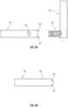
- Figure 2shows both the clamping connector 10 of Figures 1a to 1g as well as further details of a butt connection in this example between a front end 32 of a first hollow profile 34, which in this example is oriented horizontally and can be, for example, a tubular cross member of a table frame, of a furniture frame and a second hollow profile 36 of the furniture frame, which in this example is oriented vertically and can be, for example, a side part of a table frame.
- the connection in this exampleserves to produce a connection at a right angle between the first and second hollow profiles 34 and 36 at the front end 32 of the first hollow profile and in the side region of the longitudinal end 38 of the second hollow profile 36.
- both the first hollow profile 34 and the second hollow profile 36are square profiles.
- the front end 32 of the first hollow profile 34has a nose 40 or 42 projecting in the longitudinal direction at the top and bottom (see example Figure 3a ) and the second hollow profile 36 has on its longitudinal side 44 corresponding contours 46 and 48 (keyhole contour) for tapping, wherein the contour 48 also serves to let through the plate-shaped part 20 of the sliding block 16 in the upper region and to clamp only the rod-shaped part 22 of the sliding block 16 in the lower region.
- contour 48also serves to let through the plate-shaped part 20 of the sliding block 16 in the upper region and to clamp only the rod-shaped part 22 of the sliding block 16 in the lower region.
- the lugs 40 and 42have different widths (see example Figure 3b ) to prevent twisting.
- the lugs 42 and 40engage with the contours 38 and 46 respectively and serve to absorb vertical forces.
- the lower nose 40is narrower than the upper nose 42.
- Figure 2a bore 50 in the side wall of the first hollow profile 34 and a (second) screw 52, in this example a countersunk screw, for passing through the bore 50 and fastening the clamping body 12 by means of the second screw 52 to the first hollow profile 34, more precisely to the longitudinal end thereof.
- a (second) screw 52in this example a countersunk screw
- FIGS 3a to 3cshow a phase of establishing the connection between the Figure 2 shown first and second hollow profiles 34 and 36.
- the clamping body 12 and the slot nut 16are first connected to one another by means of the (first) screw 30 and then the slot nut 16 is "hung" in the contour 48 and by tightening the (first) screw 30 in this example at a right angle to the second hollow profile 36 in a force-fitting and form-fitting manner (see example Figures 5a-5c ).
- the first hollow profile 34is then pushed with its front end 32 over the clamping connector 10 and the first hollow profile is fastened to the clamping connector 10 by means of the second screw 52.
- the clamping body 10has appropriate external dimensions for insertion into the front end 32, preferably such that it fits at least almost form-fittingly into the front end 32, but can still be moved somewhat therein.
- the phase of the second screwcollides with the first hollow profile 34 when screwed into the clamping connector 10 and presses it in the direction of the second hollow profile 36. This results in a preload.
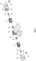
- Figure 4shows the possibility of connecting on both sides by mirroring.
- a clamping connector 10is provided on both sides to create a respective connection.
- FIGS 5a to 5cshow by way of example how a T-shaped slot nut 16, if it has already been inserted into the Figure 2 shown contour 46 has been inserted, by tightening a screw, for example the one in Figure 2 shown screw 30, towards a clamping body, e.g. one in the Figure 2 shown clamping body 12, and thus in the Figures 5a to 5c progressively to the right against the inside of a hollow profile, for example the one in the Figure 2 shown second hollow profile 36, so that a force- and form-fitting connection is created.
- a screwfor example the one in Figure 2 shown screw 30
- a clamping bodye.g. one in the Figure 2 shown clamping body 12
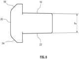
- the Figure 6shows a side view of a T-shaped sliding block 16 according to a particular embodiment of the present invention.
- the sliding block 16has a substantially plate-shaped part 20 and a substantially rod-shaped part 22.
- the plate-shaped part 20has lateral bevels 54 and 56.
- the rod-shaped part 22can, for example, have a square, round or oval cross-section.
- the rod-shaped parthas a rectangular or oval cross-section. square cross-section. However, this tapers slightly towards its end, so that the rod-shaped part 22 is conical.
- the cone angle in the Figure 61° at the top and bottom.
- receiving openingfor example the one in the Figure 1c shown receiving opening 58
- thisallows a force- and form-fitting connection between the sliding block 16 and a clamping body, such as the clamping body 12 in the Figure 1c , to reach.
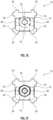
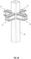
- the Figures 7a to 7cshow an example of a four-sided connection of clamping connectors 10 to a, in this example vertical, first hollow profile 34 with contours 46 and 48 as in the Figure 2 .
- the Figure 7ashows the hollow profile 34 alone and the Figure 7b shows the hollow profile 34 with four clamping connectors 10 arranged at right angles to each other.
- the Figure 7cshows a top view.
- bevels 54 and 56, as for example in the Figure 6 shown, of plate-shaped parts 20 of sliding blocks 16enable a space-saving arrangement of the sliding blocks 16 and thus a space-saving connection of, in this example, four clamping connectors 10 at right angles.
Landscapes
- Engineering & Computer Science (AREA)
- General Engineering & Computer Science (AREA)
- Mechanical Engineering (AREA)
- Furniture Connections (AREA)
Abstract
Translated fromGermanDescription
Translated fromGermanDie vorliegende Erfindung betrifft einen Spannverbinder zur lösbaren, vorzugsweise stumpfen, Verbindung eines Stirnendes eines ersten Hohlprofils eines Möbelgestells mit einem zweiten Hohlprofil des Möbelgestells sowie eine, vorzugsweise stumpfe, Verbindung zwischen einem Stirnende eines ersten Hohlprofils eines Möbelgestells und einem zweiten Hohlprofil des Möbelgestells mittels des Spannverbinders.The present invention relates to a clamping connector for the detachable, preferably blunt, connection of a front end of a first hollow profile of a furniture frame to a second hollow profile of the furniture frame and a, preferably blunt, connection between a front end of a first hollow profile of a furniture frame and a second hollow profile of the furniture frame by means of the clamping connector.
Möbelgestelle, wie beispielsweise Tischgestelle und Regalgestelle, bestehen häufig aus fixen Grundelementen, die durch Einsetzen verschiedener Traversen diverse Möglichkeiten in Form und Varianz abbilden. Die Traversen lassen sich häufig nur mittels unterschiedlicher Verbindungskomponenten mit den Grundelementen verbinden. Das macht die Montage verschiedenster Möbelsysteme recht umständlich.Furniture frames, such as table frames and shelf frames, often consist of fixed basic elements that can be used to create a variety of shapes and variations by inserting different crossbeams. The crossbeams can often only be connected to the basic elements using different connecting components. This makes assembling a wide variety of furniture systems quite complicated.
Der vorliegenden Erfindung liegt somit die Aufgabe zugrunde, eine einheitliche Montage verschiedenster Möbelsysteme zu ermöglichen.The present invention is therefore based on the object of enabling a uniform assembly of a wide variety of furniture systems.
Erfindungsgemäß wird diese Aufgabe gelöst durch einen Spannverbinder zur lösbaren, vorzugsweise stumpfen, Verbindung eines Stirnendes eines ersten Hohlprofils eines Möbelgestells mit einem zweiten Hohlprofil des Möbelgestells, umfassend:
- einen in das Stirnendes des ersten Hohlprofils einsetzbaren Spannkorpus mit einer Durchgangsbohrung, die in Längsrichtung des ersten Hohlprofils verläuft, wenn der Spannkorpus in das Stirnende des ersten Hohlprofils eingesetzt ist,
- einen Nutenstein mit einer Gewindebohrung,
- eine erste Schraube in der Durchgangsbohrung in dem Spannkorpus zum Befestigen des Nutensteins an dem Spannkorpus und zum kraftschlüssigen Befestigen des Spannkorpus an dem zweiten Hohlprofil, wenn ein Teil, insbesondere ein plattenförmiger Teil, des Nutensteins in eine entsprechende Kontur in dem zweiten Hohlprofil eingesetzt ist,
- wobei der Spannkorpus zusätzlich eine Gewindebohrung quer zu seiner Durchgangsbohrung zu seiner kraftschlüssigen Befestigung im Inneren des Stirnendes des ersten Hohlprofils mittels einer zweiten Schraube, die sich von außen durch eine Bohrung in der Wand des ersten Hohlprofils erstreckt, umfasst.
- a clamping body insertable into the front end of the first hollow profile with a through hole which runs in the longitudinal direction of the first hollow profile when the clamping body is inserted into the front end of the first hollow profile,
- a slotted nut with a threaded hole,
- a first screw in the through hole in the clamping body for fastening the slot nut to the clamping body and for force-fitting fastening of the clamping body to the second hollow profile when a part, in particular a plate-shaped part, of the slot nut is inserted into a corresponding contour in the second hollow profile,
- wherein the clamping body additionally comprises a threaded bore transverse to its through-bore for its force-fitting fastening in the interior of the front end of the first hollow profile by means of a second screw which extends from the outside through a bore in the wall of the first hollow profile.
Vorzugsweise weist der Spannkorpus (zusätzliche) Längsrippen zur Positionierung und Zentrierung im Inneren des Stirnendes des ersten Hohlprofils auf.Preferably, the clamping body has (additional) longitudinal ribs for positioning and centering inside the front end of the first hollow profile.
Weiterhin wird diese Aufgabe gelöst durch eine, vorzugsweise stumpfe, Verbindung zwischen einem Stirnende eines ersten Hohlprofils eines Möbelgestells und einem zweiten Hohlprofil des Möbelgestells mittels des Spannverbinders nach Anspruch 1, wobei der Nutenstein des Spannverbinders mittels der sich in der Durchgangsbohrung des Spannverbinders erstreckenden ersten Schraube des Spannverbinders am Spannkorpus des Spannverbinders befestigt ist, der Spannverbinder in das Stirnende des ersten Hohlprofils so eingesetzt ist, dass der Nutenstein über das Stirnende des ersten Hohlprofils vorsteht, und ein Teil, insbesondere ein plattenförmiger Teil, des Nutensteins in eine Kontur in der Wand des zweiten Hohlprofils eingesetzt ist, und der Spannkorpus mittels des Nutensteins und der ersten Schraube an dem zweiten Hohlprofil kraftschlüssig befestigt ist und mittels eines zweiten Schraube, die sich von außen durch eine Bohrung in der Wand des erste Hohlprofils quer zur Durchgangsbohrung im Spannverbinder erstreckt und in die Gewindebohrung im Spannkorpus geschraubt ist, im Inneren des Stirnendes des ersten Hohlprofils kraftschlüssig befestigt ist.Furthermore, this object is achieved by a preferably blunt connection between a front end of a first hollow profile of a furniture frame and a second hollow profile of the furniture frame by means of the clamping connector according to claim 1, wherein the slot nut of the clamping connector is fastened to the clamping body of the clamping connector by means of the first screw of the clamping connector extending in the through hole of the clamping connector, the clamping connector is inserted into the front end of the first hollow profile in such a way that the slot nut protrudes beyond the front end of the first hollow profile, and a part, in particular a plate-shaped part, of the slot nut is inserted into a contour in the wall of the second hollow profile, and the clamping body is non-positively fastened to the second hollow profile by means of the slot nut and the first screw and by means of a second screw which extends from the outside through a hole in the wall of the first hollow profile transversely to the through hole in the clamping connector and is screwed into the threaded hole in the clamping body, inside the front end of the first hollow profile is firmly attached.
Vorteilhafterweise ist der Spannverbinder in das Stirnende des ersten Hohlprofils in eine spezielle Kontur eingesetzt. Die spezielle Kontur ist vorzugsweise vierseitig. Die Hohlprofile können dabei z. B. rechtwinklig aufeinanderstoßen und z. B. T-förmig aufeinandertreffen.The clamping connector is advantageously inserted into the front end of the first hollow profile in a special contour. The special contour is preferably four-sided. The hollow profiles can meet at right angles or in a T-shape, for example.
Bei dem Spannverbinder kann vorgesehen sein, dass die erste Schraube eine Zylinderkopfschraube ist.The clamping connector can be designed so that the first screw is a cylinder head screw.
Vorzugsweise ist der Nutenstein ein T-Nutenstein mit einem plattenförmigen Teil und einem stabförmigen, insbesondere konusförmigen, Teil.Preferably, the slot nut is a T-slot nut with a plate-shaped part and a rod-shaped, in particular cone-shaped, part.
In einer besonderen Ausführungsform der Verbindung weist das Stirnende des ersten Hohlprofils mindestens eine in Längsrichtung vorstehende Nase und das zweite Hohlprofil eine korrespondierende Kontur zur formschlüssigen Positionierung des Stirnendes des ersten Hohlprofils an dem zweiten Hohlprofil auf.In a particular embodiment of the connection, the front end of the first hollow profile has at least one nose protruding in the longitudinal direction and the second hollow profile has a corresponding contour for the positive positioning of the front end of the first hollow profile on the second hollow profile.
Weiterhin kann vorgesehen sein, dass das erste Hohlprofil horizontal verläuft und/oder das zweite Hohlprofil vertikal verläuft.Furthermore, it can be provided that the first hollow profile runs horizontally and/or the second hollow profile runs vertically.
Zweckmäßigerweise ist/sind das erste Hohlprofil und/oder das zweite Hohlprofil ein Vierkantprofil.Conveniently, the first hollow profile and/or the second hollow profile is/are a square profile.
In einer weiteren besonderen Ausführungsform ist/sind das erste Hohlprofil und/oder das zweite Hohlprofil ein Rundprofil.In a further particular embodiment, the first hollow profile and/or the second hollow profile is/are a round profile.
Vorteilhafterweise ist die erste Schraube eine Zylinderkopfschraube.Advantageously, the first screw is a cylinder head screw.
Ferner kann vorgesehen sein, dass die zweite Schraube eine Senkkopfschraube ist.Furthermore, it can be provided that the second screw is a countersunk head screw.
Insbesondere kann dabei vorgesehen sein, dass die Längsachse der Bohrung in der Wand des ersten Hohlprofils und die Längsachse der Gewindebohrung im Spannkorpus mit einem Versatz zueinander in Richtung zum zweiten Hohlprofil gefertigt sind derart, dass der Senkkopf der Senkkopfschraube im Einbauzustand eine Kraft auf die Wandung der Bohrung im ersten Hohlprofil in Richtung zum zweiten Hohlprofil ausübt.In particular, it can be provided that the longitudinal axis of the bore in the wall of the first hollow profile and the longitudinal axis of the threaded bore in the clamping body with are manufactured with an offset from one another in the direction of the second hollow profile in such a way that the countersunk head of the countersunk head screw, when installed, exerts a force on the wall of the bore in the first hollow profile in the direction of the second hollow profile.
Außerdem kann das Möbelgestell ein Tischgestell sein.In addition, the furniture frame can be a table frame.
Insbesondere kann das erste Hohlprofil eine Traverse und das zweite Hohlprofil ein Seitenteil sein.In particular, the first hollow profile can be a cross member and the second hollow profile can be a side part.
Alternativ kann das Möbelgestell ein(e) starre(s) oder mobile(s) Einheit/Gestell, wie z.B. ein Regalgestell oder ein Whiteboardwagen, sein.Alternatively, the furniture frame can be a rigid or mobile unit/frame, such as a shelving unit or a whiteboard cart.
Der Spannverbinder bzw. die Verbindung kann auch zur Verkettung von Möbelgestellkomponenten verwendet werden. Insbesondere ist damit eine flexible Verkettung von unterschiedlichen Möbelgestellen und somit eine Erweiterung möglich.The clamping connector or connection can also be used to link furniture frame components. In particular, it enables flexible linking of different furniture frames and thus expansion.
Der Erfindung liegt die überraschende Erkenntnis zugrunde, dass der Spannverbinder eine universelle Verbindung und einfache Montage ermöglicht. Insbesondere ist ein segmentweiser Aufbau von z. B. Regalen, Möbeln und Tischen möglich. Eine Auslieferung kann je nach Form und Ausführung zerlegt oder vormontiert erfolgen. Es ist auch eine Verkettung von Komponenten möglich.The invention is based on the surprising discovery that the clamping connector enables a universal connection and simple assembly. In particular, a segmented construction of shelves, furniture and tables is possible. Depending on the shape and design, the product can be delivered disassembled or pre-assembled. It is also possible to link components together.
Zumindest in besonderen Ausführungsformen:
- werden gleiche Rohrprofile eingesetzt, und/oder
- werden Normschrauben verwendet, und/oder
- wird ein einzelner Nutenstein verwendet, der mit einer Schraube an einen Spannkörper herangezogen wird, und/oder
- wird zusätzlich eine konische Form eines Nutensteins zur formschlüssigen Fixierung in einem Rohrprofil genutzt, und/oder
- werden am Spannkörper auf jeder Seite zwei Auflagebacken zur Zentrierung genutzt, die vorzugsweise als leichte Übergangspassung ausgelegt sind, und/oder
- können 360°-Anbindungen abgebildet werden, und/oder
- wird eine Schlüsselochkontur im Rohrprofil genutzt, die ein Verrutschen des Nutensteins zusätzlich vermeidet, und/oder
- werden zusätzlich Konturen und Nasen zur weiteren Verstärkung verwendet.
- the same pipe profiles are used, and/or
- standard screws are used, and/or
- a single slot nut is used, which is tightened to a clamping body with a screw, and/or
- In addition, a conical shape of a slot nut is used for form-fitting fixation in a pipe profile, and/or
- two support jaws are used on each side of the clamping body for centering, which are preferably designed as a slight transition fit, and/or
- 360° connections can be mapped, and/or
- a keyhole contour is used in the pipe profile, which additionally prevents the slot nut from slipping, and/or
- Additional contours and noses are used for further reinforcement.
Weitere Merkmale und Vorteile der Erfindung ergeben sich aus den beigefügten Ansprüchen und aus der nachfolgenden ausführlichen Beschreibung von bevorzugten Ausführungsbeispielen anhand der schematischen Zeichnungen. Dabei zeigt/zeigen:
Figur 1a : eine Explosionsansicht von einem Spannverbinder gemäß einer besonderen Ausführungsform der vorliegenden Erfindung;Figuren 1b bis 1g : diverse Ansichten des Spannverbinders (10) vonFigur 1 im zusammengebauten Zustand;Figur 2 : eine Explosionsansicht einer Verbindung gemäß einer besonderen Ausführungsform der vorliegenden Erfindung;Figur 3a : eine Seitenansicht von einem ersten Hohlprofil einem zweiten Hohlprofil vor einer Verbindung derselben;Figur 3b : eine Schnittansicht A-A vonFigur 3a ;Figur 3c : eine Detailansicht Z vonFigur 3b ;Figur 3d : die Detailansicht vonFigur 3c nach Befestigung des ersten Hohlprofils; undFigur 4 : eine Explosionsansicht von beidseitigen Verbindungen gemäß einer weiteren besonderen Ausführungsform der vorliegenden Erfindung.Figur 5a bis 5c : Einzelheiten des Festziehens eines T-förmigen Nutensteins;Figur 6 : eine Seitenansicht von einem T-förmigen Nutenstein gemäß einer besonderen Ausführungsform der vorliegenden Erfindung; undFiguren 7a bis 7c : perspektivische Ansichten von einer vierseitigen Anbindung eines Spannverbinders an einem Hohlprofil in Form eines beispielhaften Vierkantprofils gemäß einer besonderen Ausführungsform der vorliegenden Erfindung.
Figure 1a : an exploded view of a clamping connector according to a particular embodiment of the present invention;Figures 1b to 1g : various views of the clamping connector (10) fromFigure 1 in assembled condition;Figure 2 : an exploded view of a connection according to a particular embodiment of the present invention;Figure 3a : a side view of a first hollow profile and a second hollow profile before connection thereof;Figure 3b : a sectional view AA ofFigure 3a ;Figure 3c : a detailed view Z ofFigure 3b ;Figure 3d : the detailed view ofFigure 3c after fixing the first hollow profile; andFigure 4 : an exploded view of bilateral connections according to another particular embodiment of the present invention.Figures 5a to 5c : Details of tightening a T-nut;Figure 6 : a side view of a T-shaped slot nut according to a particular embodiment of the present invention; andFigures 7a to 7c : Perspective views of a four-sided connection of a clamping connector to a hollow profile in the form of an exemplary square profile according to a particular embodiment of the present invention.
Der in den
Der Spannkörper 12 weist einen im Wesentlichen viereckigen, insbesondere quadratischen, Querschnitt mit Längsrippen 24 in seinen Eckbereichen auf. In diesem Beispiel sind zwei Längsrippen 24 pro Seite vorgesehen. Die Längsrippen 24 dienen in diesem Beispiel als Auflagebacken. Die Durchgangsbohrung 14 weist in diesem Beispiel, ausgehend vom in der
Ferner weist der Spannkorpus im Bereich seines ersten Abschnitts A1 gegenüberliegende Gewindebohrungen 26 und 28 auf, die sich quer zur Längserstreckung der Durchgangsbohrung 14 durch die Wand des Spannkorpus 12 erstrecken.Furthermore, the clamping body has, in the region of its first section A1, opposite threaded bores 26 and 28 which extend transversely to the longitudinal extension of the through-
Des Weiteren umfasst der Spannverbinder 12 eine (erste) Schraube 30, in diesem Beispiel eine Zylinderkopfschraube, zum Befestigen des Nutensteins 16 an dem Spannkorpus 10. Dazu sind die Durchmesser d2 und d3 der Durchgangsbohrung 14 so gewählt, dass ein Schaft der (ersten) Schraube 30 hindurchtreten kann, während der erste Durchmesser d1 der Durchgangsbohrung 14 so gewählt ist, dass im ersten Abschnitt A1 der Durchgangsbohrung 14 der Kopf der (ersten) Schraube 30 Platz hat und an dem Absatz zum zweiten Abschnitt A2 mit dem zweiten Durchmesser d2 aufliegen kann.Furthermore, the clamping
Die Längsrippen 24 des Spannkorpus 12 weisen auf der in der
Sowohl das erste Hohlprofil 34 als auch das zweite Hohlprofil 36 sind in diesem Beispiel Vierkantprofile.In this example, both the first
Das Stirnende 32 des ersten Hohlprofils 34 weist oben und unten jeweils eine in Längsrichtung vorstehende Nase 40 bzw. 42 (s. beispielhaft
Vorzugsweise weisen die Nasen 40 und 42 unterschiedliche Breiten (s. beispielhaft
In diesem Beispiel ist die untere Nase 40 schmaler als die obere Nase 42.In this example, the
Des Weiteren sind in der
Die
Wie sich in Kombination mit der
Der Spannkorpus 10 weist zum Einsetzen in das Stirnende 32 entsprechende Außenabmessungen auf, vorzugsweise so dass er zumindest nahezu formschlüssig in das Stirnende 32 passt, aber sich darin noch etwas verschieben lässt.The clamping
Da die Bohrung 50 in dem ersten Hohlprofil 32 nicht konzentrisch zur zweiten Schraube 52 ist, kollidiert die Phase der zweiten Schraube, hier Senkkopfschraube, 52 beim Einschrauben in den Spannverbinder 10 mit dem ersten Hohlprofil 34 und drückt dieses in Richtung zum zweiten Hohlprofil 36. Somit kommt es zu einer Vorspannung.Since the
Die
Die
Die
Die
Die in der vorstehenden Beschreibung, in den Zeichnungen sowie in den Ansprüchen offenbarten Merkmale der Erfindung können sowohl einzeln als auch in den beliebigen Kombinationen für die Verwirklichung der Erfindung in ihren verschiedenen Ausführungsformen wesentlich sein.The features of the invention disclosed in the above description, in the drawings and in the claims may be essential for the realization of the invention in its various embodiments both individually and in any combination.
- 1010
- Spannverbinderclamping connectors
- 1212
- Spannkorpusclamping body
- 1414
- Durchgangsbohrungthrough hole
- 1616
- Nutensteinslotted nut
- 1818
- Gewindebohrungthreaded hole
- 2020
- plattenförmiger Teilplate-shaped part
- 2222
- stabförmiger Teilrod-shaped part
- 2424
- Längsrippenlongitudinal ribs
- 26, 2826, 28
- Gewindebohrungenthreaded holes
- 3030
- erste Schraubefirst screw
- 3232
- Stirnendeforehead
- 3434
- erstes Hohlprofilfirst hollow profile
- 3636
- zweites Hohlprofilsecond hollow profile
- 3838
- Längsendelongitudinal end
- 40, 4240, 42
- Nasennoses
- 4444
- Längsseitelong side
- 46, 4846, 48
- Konturencontours
- 5050
- Bohrungdrilling
- 5252
- zweite Schraubesecond screw
- 54,5654.56
- Fasenchamfers
- 5858
- Aufnahmeöffnungreceiving opening
- A1A1
- erster Abschnittfirst section
- A2A2
- zweiter Abschnittsecond section
- A3A3
- dritter Abschnittthird section
- d1d1
- erster Durchmesserfirst diameter
- d2d2
- zweiter Durchmessersecond diameter
- d3d3
- dritter Durchmesserthird diameter
- vv
- Versatzoffset
Claims (14)
Translated fromGermanApplications Claiming Priority (1)
| Application Number | Priority Date | Filing Date | Title |
|---|---|---|---|
| DE202023103577.9UDE202023103577U1 (en) | 2023-06-28 | 2023-06-28 | Clamping connector for the releasable, preferably blunt, connection of a front end of a first hollow profile of a furniture frame with a second hollow profile of the furniture frame and, preferably blunt, connection by means of the same |
Publications (1)
| Publication Number | Publication Date |
|---|---|
| EP4484768A1true EP4484768A1 (en) | 2025-01-01 |
Family
ID=87930474
Family Applications (1)
| Application Number | Title | Priority Date | Filing Date |
|---|---|---|---|
| EP24183921.6APendingEP4484768A1 (en) | 2023-06-28 | 2024-06-24 | Fixing connector for a detachable, preferably blunt, connection of a first hollow profile of a furniture frame |
Country Status (2)
| Country | Link |
|---|---|
| EP (1) | EP4484768A1 (en) |
| DE (1) | DE202023103577U1 (en) |
Citations (3)
| Publication number | Priority date | Publication date | Assignee | Title |
|---|---|---|---|---|
| DE2131497A1 (en)* | 1970-06-26 | 1972-01-05 | Jean Lahet | Arrangement for the connection of at least two tubular profile bars with each other |
| JPS6019806U (en)* | 1983-07-19 | 1985-02-12 | 日本プライメタル株式会社 | Connection device for tubular members |
| KR101525008B1 (en)* | 2014-06-05 | 2015-06-03 | 정형진 | Connector for aluminium profile |
- 2023
- 2023-06-28DEDE202023103577.9Upatent/DE202023103577U1/enactiveActive
- 2024
- 2024-06-24EPEP24183921.6Apatent/EP4484768A1/enactivePending
Patent Citations (3)
| Publication number | Priority date | Publication date | Assignee | Title |
|---|---|---|---|---|
| DE2131497A1 (en)* | 1970-06-26 | 1972-01-05 | Jean Lahet | Arrangement for the connection of at least two tubular profile bars with each other |
| JPS6019806U (en)* | 1983-07-19 | 1985-02-12 | 日本プライメタル株式会社 | Connection device for tubular members |
| KR101525008B1 (en)* | 2014-06-05 | 2015-06-03 | 정형진 | Connector for aluminium profile |
Also Published As
| Publication number | Publication date |
|---|---|
| DE202023103577U1 (en) | 2023-08-22 |
Similar Documents
| Publication | Publication Date | Title |
|---|---|---|
| DE69301237T2 (en) | FURNITURE WITH TUBULAR BASE | |
| EP3721029B1 (en) | Device with a beam and two post conneection adapters to support a scaffold | |
| DE29614265U1 (en) | Shelving system | |
| DE202017107404U1 (en) | Node connector for profile systems or the like | |
| EP0136431A2 (en) | Sectional frame | |
| EP1615528B2 (en) | Connecting element and frame system | |
| WO1999058362A1 (en) | Supporting and fastening device for contact wires | |
| EP0287070B1 (en) | Arrangement for releasably connecting two tubes abutting end to end | |
| EP2138069B1 (en) | Component for manufacturing a multi-function writing or work desk | |
| EP4484768A1 (en) | Fixing connector for a detachable, preferably blunt, connection of a first hollow profile of a furniture frame | |
| EP1439269A1 (en) | Bracket for mounting profiles for sanitary installations and frame with such a bracket | |
| EP4114150A1 (en) | Expansion building set | |
| DE102007014263B3 (en) | Connecting nodes for erecting a supporting framework connect first flattening areas of first elements on one side forming lug-shaped end regions and lateral recesses to each other | |
| DE29706495U1 (en) | Connection body for connecting longitudinal elements | |
| DE3320962C2 (en) | Corner connection | |
| EP3406916B1 (en) | Angle connector for loadbearing sections | |
| DE20110322U1 (en) | Arrangement for connecting in particular tubular objects | |
| DE102017005297B4 (en) | Adjustable fitting | |
| DE10103967C1 (en) | Connection system e.g. for furniture frame, has rod provided with pins allowing insertion in opening in support upright in given angular position | |
| DE202017107484U1 (en) | Carrying device with a support arm for carrying an object | |
| EP3828426B1 (en) | Connection element for multi-edge pipes | |
| EP3517793B1 (en) | Pipe coupling device | |
| EP3406918B1 (en) | Method for reversibly connecting a first and second shelf component for a shelving unit, assembly for a shelving unit and shelving unit | |
| DE202022107179U1 (en) | Base and table | |
| EP0055861A1 (en) | Fastening means for furniture |
Legal Events
| Date | Code | Title | Description |
|---|---|---|---|
| PUAI | Public reference made under article 153(3) epc to a published international application that has entered the european phase | Free format text:ORIGINAL CODE: 0009012 | |
| STAA | Information on the status of an ep patent application or granted ep patent | Free format text:STATUS: REQUEST FOR EXAMINATION WAS MADE | |
| 17P | Request for examination filed | Effective date:20240624 | |
| AK | Designated contracting states | Kind code of ref document:A1 Designated state(s):AL AT BE BG CH CY CZ DE DK EE ES FI FR GB GR HR HU IE IS IT LI LT LU LV MC ME MK MT NL NO PL PT RO RS SE SI SK SM TR |