EP4474337A1 - Device and method for dispensing a liquid starting component of a bone cement paste - Google Patents
Device and method for dispensing a liquid starting component of a bone cement pasteDownload PDFInfo
- Publication number
- EP4474337A1 EP4474337A1EP23177507.3AEP23177507AEP4474337A1EP 4474337 A1EP4474337 A1EP 4474337A1EP 23177507 AEP23177507 AEP 23177507AEP 4474337 A1EP4474337 A1EP 4474337A1
- Authority
- EP
- European Patent Office
- Prior art keywords
- glass ampoule
- starting component
- bone cement
- ampoule
- liquid starting
- Prior art date
- Legal status (The legal status is an assumption and is not a legal conclusion. Google has not performed a legal analysis and makes no representation as to the accuracy of the status listed.)
- Pending
Links
- 239000007788liquidSubstances0.000titleclaimsabstractdescription126
- 239000002639bone cementSubstances0.000titleclaimsabstractdescription111
- 238000000034methodMethods0.000titleclaimsdescription14
- 239000003708ampulSubstances0.000claimsabstractdescription215
- 239000011521glassSubstances0.000claimsabstractdescription159
- 238000002156mixingMethods0.000claimsdescription108
- 239000000843powderSubstances0.000claimsdescription25
- 229920001971elastomerPolymers0.000claimsdescription13
- 239000012634fragmentSubstances0.000claimsdescription7
- 239000013013elastic materialSubstances0.000claimsdescription5
- 238000007599dischargingMethods0.000claims1
- 239000000463materialSubstances0.000description16
- 229920003229poly(methyl methacrylate)Polymers0.000description15
- 239000004926polymethyl methacrylateSubstances0.000description15
- 239000000654additiveSubstances0.000description14
- 239000000178monomerSubstances0.000description13
- 230000000996additive effectEffects0.000description12
- 230000005484gravityEffects0.000description9
- 239000003242anti bacterial agentSubstances0.000description7
- 229940088710antibiotic agentDrugs0.000description6
- VVQNEPGJFQJSBK-UHFFFAOYSA-NMethyl methacrylateChemical compoundCOC(=O)C(C)=CVVQNEPGJFQJSBK-UHFFFAOYSA-N0.000description5
- 239000003795chemical substances by applicationSubstances0.000description5
- 239000003999initiatorSubstances0.000description5
- 230000002093peripheral effectEffects0.000description5
- VYPSYNLAJGMNEJ-UHFFFAOYSA-NSilicium dioxideChemical compoundO=[Si]=OVYPSYNLAJGMNEJ-UHFFFAOYSA-N0.000description4
- 238000012986modificationMethods0.000description4
- 230000004048modificationEffects0.000description4
- 229920000642polymerPolymers0.000description4
- 230000008569processEffects0.000description4
- 230000001960triggered effectEffects0.000description4
- 239000013543active substanceSubstances0.000description3
- 239000012530fluidSubstances0.000description3
- 238000004519manufacturing processMethods0.000description3
- 239000002245particleSubstances0.000description3
- 238000006116polymerization reactionMethods0.000description3
- -1polypropylenePolymers0.000description3
- 238000003825pressingMethods0.000description3
- 239000000126substanceSubstances0.000description3
- OMPJBNCRMGITSC-UHFFFAOYSA-NBenzoylperoxideChemical compoundC=1C=CC=CC=1C(=O)OOC(=O)C1=CC=CC=C1OMPJBNCRMGITSC-UHFFFAOYSA-N0.000description2
- VTYYLEPIZMXCLO-UHFFFAOYSA-LCalcium carbonateChemical compound[Ca+2].[O-]C([O-])=OVTYYLEPIZMXCLO-UHFFFAOYSA-L0.000description2
- 241001295925GegenesSpecies0.000description2
- BAPJBEWLBFYGME-UHFFFAOYSA-NMethyl acrylateChemical compoundCOC(=O)C=CBAPJBEWLBFYGME-UHFFFAOYSA-N0.000description2
- PPBRXRYQALVLMV-UHFFFAOYSA-NStyreneChemical compoundC=CC1=CC=CC=C1PPBRXRYQALVLMV-UHFFFAOYSA-N0.000description2
- GWEVSGVZZGPLCZ-UHFFFAOYSA-NTitan oxideChemical compoundO=[Ti]=OGWEVSGVZZGPLCZ-UHFFFAOYSA-N0.000description2
- 208000027418Wounds and injuryDiseases0.000description2
- 230000009471actionEffects0.000description2
- TZCXTZWJZNENPQ-UHFFFAOYSA-Lbarium sulfateChemical compound[Ba+2].[O-]S([O-])(=O)=OTZCXTZWJZNENPQ-UHFFFAOYSA-L0.000description2
- 238000005452bendingMethods0.000description2
- 235000019400benzoyl peroxideNutrition0.000description2
- 210000000988bone and boneAnatomy0.000description2
- 239000001913celluloseSubstances0.000description2
- 229920002678cellulosePolymers0.000description2
- 230000006378damageEffects0.000description2
- 238000011161developmentMethods0.000description2
- 125000002887hydroxy groupChemical group[H]O*0.000description2
- 208000014674injuryDiseases0.000description2
- 239000000203mixtureSubstances0.000description2
- GYVGXEWAOAAJEU-UHFFFAOYSA-Nn,n,4-trimethylanilineChemical compoundCN(C)C1=CC=C(C)C=C1GYVGXEWAOAAJEU-UHFFFAOYSA-N0.000description2
- 229920003023plasticPolymers0.000description2
- 239000004033plasticSubstances0.000description2
- 230000000717retained effectEffects0.000description2
- 239000000377silicon dioxideSubstances0.000description2
- 235000012239silicon dioxideNutrition0.000description2
- 229920002943EPDM rubberPolymers0.000description1
- CEAZRRDELHUEMR-URQXQFDESA-NGentamicinChemical compoundO1[C@H](C(C)NC)CC[C@@H](N)[C@H]1O[C@H]1[C@H](O)[C@@H](O[C@@H]2[C@@H]([C@@H](NC)[C@@](C)(O)CO2)O)[C@H](N)C[C@@H]1NCEAZRRDELHUEMR-URQXQFDESA-N0.000description1
- 229930182566GentamicinNatural products0.000description1
- 239000004698PolyethyleneSubstances0.000description1
- 239000004743PolypropyleneSubstances0.000description1
- 229920002472StarchPolymers0.000description1
- MCMNRKCIXSYSNV-UHFFFAOYSA-NZrO2Inorganic materialsO=[Zr]=OMCMNRKCIXSYSNV-UHFFFAOYSA-N0.000description1
- 238000010521absorption reactionMethods0.000description1
- 239000012190activatorSubstances0.000description1
- 230000003115biocidal effectEffects0.000description1
- 229910000019calcium carbonateInorganic materials0.000description1
- MYPYJXKWCTUITO-KIIOPKALSA-Nchembl3301825Chemical compoundO([C@@H]1[C@@H](O)[C@H](O)[C@@H](CO)O[C@H]1OC1=C2C=C3C=C1OC1=CC=C(C=C1Cl)[C@@H](O)[C@H](C(N[C@@H](CC(N)=O)C(=O)N[C@H]3C(=O)N[C@H]1C(=O)N[C@H](C(N[C@H](C3=CC(O)=CC(O)=C3C=3C(O)=CC=C1C=3)C(O)=O)=O)[C@H](O)C1=CC=C(C(=C1)Cl)O2)=O)NC(=O)[C@@H](CC(C)C)NC)[C@H]1C[C@](C)(N)C(O)[C@H](C)O1MYPYJXKWCTUITO-KIIOPKALSA-N0.000description1
- 229960002227clindamycinDrugs0.000description1
- KDLRVYVGXIQJDK-AWPVFWJPSA-NclindamycinChemical compoundCN1C[C@H](CCC)C[C@H]1C(=O)N[C@H]([C@H](C)Cl)[C@@H]1[C@H](O)[C@H](O)[C@@H](O)[C@@H](SC)O1KDLRVYVGXIQJDK-AWPVFWJPSA-N0.000description1
- 238000011109contaminationMethods0.000description1
- 229920001577copolymerPolymers0.000description1
- 230000001419dependent effectEffects0.000description1
- 238000009826distributionMethods0.000description1
- 239000000806elastomerSubstances0.000description1
- 238000005516engineering processMethods0.000description1
- 210000000501femur bodyAnatomy0.000description1
- 239000000835fiberSubstances0.000description1
- 238000009472formulationMethods0.000description1
- 229960002518gentamicinDrugs0.000description1
- 210000004394hip jointAnatomy0.000description1
- 238000003780insertionMethods0.000description1
- 230000037431insertionEffects0.000description1
- 210000000629knee jointAnatomy0.000description1
- 239000012528membraneSubstances0.000description1
- RVTZCBVAJQQJTK-UHFFFAOYSA-Noxygen(2-);zirconium(4+)Chemical compound[O-2].[O-2].[Zr+4]RVTZCBVAJQQJTK-UHFFFAOYSA-N0.000description1
- 229920000573polyethylenePolymers0.000description1
- 229920001155polypropylenePolymers0.000description1
- 229920001296polysiloxanePolymers0.000description1
- 239000011148porous materialSubstances0.000description1
- 238000002360preparation methodMethods0.000description1
- 230000001698pyrogenic effectEffects0.000description1
- 230000000284resting effectEffects0.000description1
- 230000002441reversible effectEffects0.000description1
- 239000008107starchSubstances0.000description1
- 235000019698starchNutrition0.000description1
- 238000003860storageMethods0.000description1
- 230000008961swellingEffects0.000description1
- 239000004408titanium dioxideSubstances0.000description1
- 235000010215titanium dioxideNutrition0.000description1
- 238000012546transferMethods0.000description1
Images


Classifications
- B—PERFORMING OPERATIONS; TRANSPORTING
- B67—OPENING, CLOSING OR CLEANING BOTTLES, JARS OR SIMILAR CONTAINERS; LIQUID HANDLING
- B67B—APPLYING CLOSURE MEMBERS TO BOTTLES JARS, OR SIMILAR CONTAINERS; OPENING CLOSED CONTAINERS
- B67B7/00—Hand- or power-operated devices for opening closed containers
- B67B7/92—Hand- or power-operated devices for opening closed containers by breaking, e.g. for ampoules
- A—HUMAN NECESSITIES
- A61—MEDICAL OR VETERINARY SCIENCE; HYGIENE
- A61B—DIAGNOSIS; SURGERY; IDENTIFICATION
- A61B17/00—Surgical instruments, devices or methods
- A61B17/56—Surgical instruments or methods for treatment of bones or joints; Devices specially adapted therefor
- A61B17/58—Surgical instruments or methods for treatment of bones or joints; Devices specially adapted therefor for osteosynthesis, e.g. bone plates, screws or setting implements
- A61B17/88—Osteosynthesis instruments; Methods or means for implanting or extracting internal or external fixation devices
- A61B17/8802—Equipment for handling bone cement or other fluid fillers
- A61B17/8805—Equipment for handling bone cement or other fluid fillers for introducing fluid filler into bone or extracting it
Definitions
- the inventionrelates to a device for dispensing a liquid starting component of a bone cement dough from a glass ampoule, comprising a housing, a holder arranged in the housing for receiving a glass ampoule and an outlet for dispensing the liquid starting component from the housing.
- the inventionfurther relates to a mixing device comprising such a device and a mixing unit as well as a method for dispensing a liquid starting component of a bone cement dough by means of such a device.
- a monomer liquidis mixed with a bone cement powder by mechanical mixing, for example by means of a mixing rod.
- liquid starting componentin particular the monomer liquid for a PMMA bone cement dough.
- This liquid starting componentis often stored in glass ampoules, which offers advantages, particularly due to the ease with which such glass ampoules can be sterilized.
- the writing EP2404864B1discloses a device in which an ampoule is arranged in an ampoule holder and in which the ampoule holder is elastically deformable in the area of the ampoule neck.
- the ampoule holderis not deformable in the area of the ampoule head and the ampoule body.
- An object of the present inventionis to at least partially overcome one or more of the disadvantages resulting from the prior art.
- the inventionis based on the aim of providing a device which allows one or more glass ampoules with a liquid starting component to be opened easily, quickly and safely, in particular without causing injury.
- the glass ampoule or ampouleshould be opened with as little effort as possible and without the need for additional, separate tools.
- the glass ampouleshould be opened using as few components as possible.
- the liquid starting componentshould be available for mixing a bone cement dough with as little loss as possible and as quickly as possible.
- the monomer liquidshould be able to be pumped out of the device for providing the bone cement dough with as little effort as possible.
- the deviceshould make it possible to open several, in particular two, glass ampoules simultaneously or separately and at different times using fluid.
- the deviceshould be able to be operated with as few steps as possible in order to minimize sources of error by the user.
- the devicecan be used in combination with a mixing unit to prepare a bone cement dough.
- a liquid starting componentshould be able to be provided in a sterile and contamination-free manner using the device.
- a user of the deviceshould not come into contact with the glass ampoule to be opened.
- a first embodiment of the inventionis a device for dispensing a liquid starting component of a bone cement dough from a glass ampoule, comprising a housing, a holder arranged in the housing for receiving a glass ampoule, an outlet for dispensing the liquid starting component from the housing, characterized in that the housing has a deformable region which is designed and configured to be displaceable by pressure against the glass ampoule received in the holder and to open the glass ampoule in a fluid-conducting manner, in particular such that the liquid starting component can flow out into the device, in particular into the housing.
- the deformable region of the housing on the side facing the holderi.e. inside the housing, has a substantially dimensionally stable pressure piece which can be displaced by pressure against a glass ampoule held in the holder, in particular filled with a liquid starting component of a bone cement dough, in particular in order to open it in a fluid-conducting manner by exerting this pressure.
- This embodimentis a second embodiment of the invention, which preferably depends on the first embodiment of the invention.
- the deformable regionhas a partial region, in particular a peripheral partial region, with a thinner wall thickness than the rest of the housing.
- This embodimentis a third embodiment of the invention, which preferably depends on the first or second embodiment of the invention.
- the deformable regionis formed at least in sections from an elastic material, in particular to allow the deformable region to be returned to its initial position essentially completely after the fluid-conducting opening of a glass ampoule.
- This embodimentis a fourth embodiment of the invention, which preferably depends on one of the preceding embodiments of the invention.
- the deformable regionis arranged between the holder and the outlet.
- This embodimentis a fifth embodiment of the invention, which preferably depends on one of the preceding embodiments of the invention.
- the holderis designed to store a glass ampoule in the housing in such a way that an ampoule head of the glass ampoule is attached to the deformable
- This embodimentis a sixth embodiment of the invention which preferably depends on one of the preceding embodiments of the invention.
- a filter elementis arranged between the holder and the outlet, designed to retain fragments of a glass ampoule opened in the device in a fluid-conducting manner.
- This embodimentis a seventh embodiment of the invention, which preferably depends on one of the preceding embodiments of the invention.
- the filter elementis arranged between the deformable region and the outlet.
- This embodimentis an eighth embodiment of the invention, which preferably depends on the seventh embodiment of the invention.
- a collection areais arranged between the holder and the outlet in order to receive a liquid starting component from a glass ampoule that is opened in a fluid-conducting manner in the device.
- This embodimentis a ninth embodiment of the invention, which preferably depends on one of the preceding embodiments of the invention.
- the devicehas a conveying means for conveying a liquid starting component, in particular a liquid starting component of a bone cement dough, from the collection area through the outlet from the device.
- a liquid starting componentin particular a liquid starting component of a bone cement dough
- the conveying meansis a rubber balloon.
- This embodimentis an eleventh embodiment of the invention, which preferably depends on the tenth embodiment of the invention.
- the conveying meansis a piston.
- This embodimentis a twelfth embodiment of the invention, which preferably depends on the tenth embodiment of the invention.
- a thirteenth embodiment of the inventionis a mixing device for providing a bone cement dough from two starting components, comprising a device according to one of the first to twelfth embodiments of the invention and a mixing unit, wherein the mixing unit is designed and arranged to prepare a bone cement dough from the two To mix the starting components of the bone cement dough, in particular to mix and thus provide.
- the devicecontains a glass ampoule with a liquid starting component as the first starting component of the bone cement dough and the mixing unit contains a bone cement powder as the second starting component of the bone cement dough.
- This embodimentis a fourteenth embodiment of the invention, which preferably depends on the thirteenth embodiment of the invention.
- rangesalso include the values referred to as limits.
- a specification of the type "in the range from X to Y" in relation to a size Atherefore means that A can assume the values X, Y and values between X and Y.
- Unilaterally limited ranges of the type "up to Y" for a size Acorrespondingly mean the value Y and less than Y.
- proximal and distalare used only to designate the spatially opposite ends of the device or other structural units of the device and do not allow any conclusions to be drawn about the orientation in relation to a human body, for example a user of the device. "Distal to " and “proximal to " or similar formulations accordingly only express the spatial arrangement of two structural units of the device in relation to one another.
- a first subject of the inventionrelates to a device for dispensing a liquid starting component of a bone cement dough from a glass ampoule, comprising a housing, a holder arranged in the housing for receiving a glass ampoule, an outlet for dispensing the liquid starting component from the housing, characterized in that the housing has a deformable region which is designed and configured to be displaceable by pressure against the glass ampoule received in the holder and to open the glass ampoule in a fluid-conducting manner, in particular such that the liquid starting component can flow out into the device, in particular into the housing.
- the deviceis used in particular for fluid-conducting opening of one or more glass ampoule or glass ampoules provided in the device.
- the housing of the devicein particular a housing wall of the housing, has a deformable area which is designed to be displaceable into an interior of the housing and thus to be pressed against a glass ampoule stored there. Via the deformable area, such a high pressure can be exerted on the glass ampoule stored in the device from outside the device, in particular by a user of the device, that it breaks open at least in sections and a liquid starting component stored in the glass ampoule can flow out into the housing. This allows a glass ampoule to be opened simply and quickly in a fluid-conducting manner without additional auxiliary elements.
- the deviceis designed to open the glass ampoule in a fluid-conducting manner under sterile conditions and to make it available for mixing the bone cement dough.
- the housingis designed for sterile storage of a glass ampoule.
- the housingis essentially sealed off from the environment of the device, preferably hermetically.
- the housing of the deviceserves to accommodate and store at least one glass ampoule.
- at least one glass ampoulePreferably, several, preferably two, glass ampoules can be stored in the housing, preferably next to one another, in particular sterile, safe for transport and preferably hermetically sealed from the outside world.
- a holderis arranged inside the housing to accommodate at least one, preferably two, glass ampoules.
- the holderpreferably encloses the at least one glass ampoule at least in sections so that it can be stored in the device in a way that is safe for transport.
- the holderalso serves to fix the at least one glass ampoule so that it can be opened in a fluid-conducting manner by applying pressure via the deformable area.
- the devicehas a fluid-conducting outlet, such as a passage such as a hose or a tube.
- a fluid-conducting outletsuch as a passage such as a hose or a tube.
- the liquid starting componentcan be provided from the device to a desired location through the outlet, in particular for mixing a bone cement dough.
- the outletcan be arranged at different locations on the device, whereby it is preferred to arrange it at a distal end, in particular at a distal end of the longitudinal axis of the device.
- the deformable regioncan be designed in different ways, as long as the deformable region is designed to be insertable into the interior of the housing in such a way that pressure can be exerted on the glass ampoule from outside the device in order to open the glass ampoule in a fluid-conducting manner.
- the deformable regionmay be formed entirely from a deformable material.
- more than one glass ampoulecan be accommodated in the holder in the device and the device has a separate deformable area for each of these glass ampoule that can be accommodated, so that each deformable area can open exactly one glass ampoule in a fluid-conducting manner.
- the devicehas a holder for two glass ampoules and two separate deformable areas. The two deformable areas are designed in such a way that each of the deformable areas can specifically open one of the two glass ampoules in a fluid-conducting manner.
- An embodiment of the deviceis characterized in that the deformable region of the housing has, at least on the side facing the holder, i.e. on the inside of the housing, a substantially dimensionally stable pressure piece which can be displaced by pressure, in particular together with the deformable region, against a glass ampoule accommodated in the holder in order to open it in a fluid-conducting manner.
- the pressure pieceis substantially dimensionally stable, i.e. during regular use of the device it is essentially not deformable by the user, which facilitates a fluid-conducting opening of a glass ampoule arranged in the holder by exerting pressure on the deformable region.
- the pressure pieceis arranged in such a way that it can be deformed at the latest when pressure is exerted. on the deformable area comes into direct contact with the glass ampoule to be opened. Furthermore, the pressure piece provides a user of the device with better protection against possible glass fragments that can arise when a glass ampoule is opened using fluid.
- the pressure pieceis attached to at least the side of a deformable material facing the holder, for example glued or positively and/or non-positively attached in a frame, in order to form a deformable area according to this embodiment.
- the deformable areaconsists centrally of the pressure piece, which is surrounded all around by a deformable material in order to form a deformable area according to this embodiment.
- the deformable regionmay be formed from a material that is easier to deform than the rest of the housing or from the same material as the rest of the housing.
- the deformable regionhas a partial region, in particular a peripheral partial region, with a thinner wall thickness than the rest of the housing.
- the housingis manufactured from a uniform material, whereby the deformable region is easier to deform than the rest of the housing.
- the rest of the housinghas a wall thickness which, although the material is deformable in itself, is essentially non-deformable for a user of the device.
- the deformable regionhas a thinner wall thickness in the peripheral partial region, i.e. in the outer partial region which borders the rest of the housing, than in its central partial region.
- the central partial regioncan be designed as an essentially dimensionally stable pressure piece.
- the housing including the deformable regionpreferably comprises a rubber-elastic material with a Shore A hardness of greater than 60, in particular the housing including the deformable region consists of such a material.
- a rubber-elastic materialwith a Shore A hardness of greater than 60
- the housing including the deformable regionconsists of such a material.
- biocompatible elastomerssuch as silicone or EPDM.
- An embodiment of the deviceis characterized in that the deformable region has a fold-like, in particular accordion-like, structure on the peripheral portion, which allows insertion in the direction of the holder. In the process, these folds are at least partially unfolded.
- An embodiment of the deviceis characterized in that the deformable region consists at least in sections, preferably at least in the peripheral part, of an elastic material. This allows the deformable area to return to its original position, or at least in the direction of its original position, after a glass ampoule stored in the holder has been opened in a fluid-conducting manner. This ensures that the deformable area does not remain in the interior of the housing during further use of the device, in particular when the liquid starting component stored in the glass ampoule flows out or is conveyed.
- the preformable areacan be arranged at different locations along the longitudinal axis of the housing.
- One embodiment of the deviceis characterized in that the deformable region is arranged spatially between the holder and the outlet.
- a glass ampoule stored in the holdercan be opened in a fluid-conducting manner in the spatial vicinity of the outlet without the liquid starting component having to flow through or past the holder in the direction of the outlet. This facilitates an essentially complete conveyance of the liquid starting component out of the device.
- the device according to the inventionis designed in particular for glass ampoules which have an ampoule body, an ampoule head and an ampoule neck which structurally connects the ampoule body and the ampoule head to one another.
- the ampoule bodyrepresents a large part of the glass ampoule and serves to hold at least a large part of the liquid starting component in its interior.
- the ampoule neckhas a smaller outer diameter than the ampoule body and serves as a predetermined breaking point for breaking off the ampoule head, which is small compared to the ampoule body.
- Such glass ampoulesare very well known to those skilled in the art.
- the holderis designed to receive an ampoule neck of a glass ampoule.
- the holderis formed as a shoulder, in particular a ring-like shoulder, wherein the ampoule neck is arranged in a passage of the holder, the ampoule body rests on one side of the shoulder and the ampoule head protrudes from the holder on the other side.
- An embodiment of the deviceis characterized in that the holder is designed to store a glass ampoule in the housing in such a way that an ampoule head of the Glass ampoule borders the deformable area of the housing.
- the deformable areacan be pressed directly onto the ampoule head by applying pressure from the outside, which breaks off more easily due to the glass ampoule's predetermined breaking point, the ampoule neck, and thus allows the liquid starting component stored in the glass ampoule to flow out.
- This embodiment of the devicemakes it easier for a user to open such a glass ampoule using fluid.
- An embodiment of the deviceis characterized in that a filter element is arranged between the holder and the outlet, designed, in particular designed and configured, to retain fragments of a glass ampoule that is opened in the device in a fluid-conducting manner in the device.
- the filter elementthus prevents contamination of the bone cement dough to be mixed with fragments of a glass ampoule.
- a glass ampouleis preferably arranged proximal to the filter element, while the outlet is arranged distal to the filter element.
- the filter elementcan, for example, comprise or consist of a sieve, a porous material or a membrane.
- the filter elementis preferably a porous disk, for example made of sintered polypropylene particles, sintered or pressed polyethylene fibers, cellulose felt or cardboard.
- One embodiment of the deviceis characterized in that the filter element is arranged between the deformable region and the outlet.
- the filter elementis arranged between the deformable region and the outlet.
- the devicecan be designed in such a way that a liquid starting component can flow directly out of a glass ampoule within the device after the glass ampoule has been opened in a fluid-conducting manner.
- a liquid starting componentcan flow directly out of a glass ampoule within the device after the glass ampoule has been opened in a fluid-conducting manner.
- itcan be useful to initially leave the liquid starting component flowing out of the glass ampoule within the device and only to transport it out of the device by actively intervening.
- an embodiment of the deviceis characterized in that a collection area is arranged between the holder and the outlet in order to collect a liquid starting component from one or more fluid-conducting opened glass ampoule or glass ampoules, preferably completely.
- the filter elementcan be arranged proximally, i.e. in the direction of the glass ampoule, distally or centrally within the collection area.
- the collection areais preferably designed such that in addition to the liquid starting component, the ampoule head(s) of the glass ampoule or glass ampoules can also be accommodated.
- the collection areais preferably dimensioned such that an ampoule head can be freely rotated in the collection area, so that any liquid starting component located in the ampoule head can flow out by rotating it. This facilitates essentially complete conveyance of a liquid starting component from the device.
- a conveying of a liquid starting component from the device, preferably from the collection area of the device, through the outletcan be triggered in different ways. For example, conveying under the exclusive influence of gravity can be made possible. For this purpose, it may be necessary to align the device in a suitable spatial manner, for example with the outlet pointing towards the floor.
- An embodiment of the deviceis characterized in that the device has a conveying means for conveying a liquid starting component from the collection area through the outlet from the device.
- the conveying meansserves to actively trigger a conveying process of the liquid starting component by a user of the device.
- the conveying meansis a rubber balloon.
- a rubber balloonis, in the broadest sense, a bubble-like hollow body made of a deformable, in particular elastic, in particular reversibly elastic, material, with a fluid-conducting opening.
- the rubber ballooncan be connected to the interior of the housing via the fluid-conducting opening in a fluid-conducting manner, so that by compressing the rubber balloon, a conveying pressure can be exerted on a liquid starting component stored inside the housing.
- the liquid starting componentcan be conveyed out of the outlet of the device by the conveying pressure.
- the rubber balloonis located at an end of the device opposite the outlet and is fluidically connected to the interior of the housing.
- the conveying meansis a piston.
- the pistoninteracts with a cylinder in such a way that pushing the piston into the cylinder exerts a conveying pressure on a liquid starting component stored inside the housing.
- the liquid starting componentcan be conveyed out of the outlet of the device by the conveying pressure.
- the housingfunctions as a cylinder for the piston.
- the cylinderis connected to the interior of the housing in a fluid-conducting manner.
- the cylinderis preferably arranged at an end of the device opposite the outlet and is there connected to the interior of the housing in a fluid-conducting manner.
- Another object of the inventionrelates to a mixing device for providing a bone cement dough from two starting components, comprising a device according to one of the preceding embodiments of the invention and a mixing unit, wherein the mixing unit is designed and configured to mix the bone cement dough from the two starting components.
- the mixing unitserves to mix a bone cement dough from a bone cement powder and the liquid starting component after conveying the liquid starting component into the mixing unit, in particular after conveying the liquid starting component into an interior of the mixing unit.
- the mixing unitpreferably has a hollow cylindrical cartridge.
- a hollow cylindrical cartridgeis a tube-like container which has an interior and a cartridge wall surrounding the interior.
- the cross-section of the cartridgecan take on any shape. Due to the simple manufacture and safer use of the device, the cross-section, and preferably also the cross-section of the interior, is circular. This allows good handling for the user and, due to the absence of edges, reduces the risk of moving parts becoming jammed within the device.
- the cartridgecan consist of a wide variety of materials or material combinations.
- the devicecan consist of a polymer.
- the polymeris preferably a transparent polymer, as this allows the user to visually check that the device is functioning properly during use.
- a discharge pistonis arranged in the cartridge in order to apply the ready-mixed bone cement dough from the mixing unit to a desired location.
- the mixing unitpreferably has a mixing element, such as a mixing rod.
- a bone cement doughcan also be mixed in the mixing unit by shaking it.
- the device and the mixing unitare connected to one another in a fluid-conducting manner via the outlet of the device.
- the device and the mixing unitare connected to one another in a linear manner.
- the device and the mixing unitare connected to one another in a fluid-conducting manner via a fluid-conducting line, such as a hose or a pipe.
- the outletopens directly into the mixing unit.
- the device and the mixing unitcan be connected or connectable to one another in a fixed manner, for example in a form-fitting and/or force-fitting and/or material-fitting manner.
- the device and the mixing unitare designed as a single piece.
- One embodiment of the mixing deviceis characterized in that the device contains a glass ampoule with a liquid starting component as the first starting component of the bone cement dough and the mixing unit contains a bone cement powder as the second starting component of the bone cement dough. This allows the bone cement dough to be provided as sterile as possible, since any transfer steps of the starting components by a user of the mixing device are eliminated and the user already receives a mixing device that is sterile and pre-filled with the starting components.
- the provision of the glass ampoule in step a.can be done by a user of the device directly before its use or the user is already provided with the device equipped with the glass ampoule, for example by the manufacturer of the device.
- a step bpressure is applied from outside the device onto the deformable region, which is thus displaced into or further into the interior of the housing and is ultimately pressed against the glass ampoule. If the force applied exceeds a limit value, the glass ampoule at least partially bursts, preferably an ampoule head of the glass ampoule breaks off, as a result of which it is opened in a fluid-conducting manner and the liquid starting component can flow out into the interior of the housing.
- the deformable regionis preferably designed in such a way that after the pressure has been stopped, it is automatically returned at least in the direction, preferably completely, to its starting position before step b.
- the liquid starting componentflows into a collection area of the device and remains there until the user of the device actively removes the liquid starting component from the device.
- step c.the liquid starting component is conveyed through the outlet of the device.
- the conveyingtakes place solely by gravity.
- the conveyingtakes place through active intervention by the user of the device.
- the user of the deviceactuates a conveying means such as a piston or a rubber balloon to convey the liquid starting component through the outlet of the device.
- the liquid starting componentis conveyed in step c. into a mixing unit connected to the device in a fluid-conducting manner according to one of the preceding embodiments, in which the liquid starting component is mixed with a Bone cement powder is mixed as a second starting component of the bone cement dough in an optional step d.
- the device and the mixing unittogether form a mixing device.
- the bone cement dough provided in the mixing unitcan be discharged directly from the latter to a desired location in an optional step e.
- the mixing devicepreferably comprises a discharge piston which is mounted axially within the mixing unit to be movable in order to discharge the bone cement dough provided from the mixing device, in particular from the mixing unit.
- the discharge pistoncan be moved by means of a discharge aid, such as a discharge gun, to discharge the bone cement dough in the mixing unit.
- the deviceis used to provide a liquid starting component for a bone cement dough.
- a bone cement doughis a substance that is suitable in the field of medical technology for creating a stable connection between artificial joints, such as hip and knee joints, and bone material. Hardening turns a bone cement dough into a bone cement.
- These bone cementsare preferably polymethyl methacrylate bone cements (PMMA bone cements). PMMA bone cements have long been used in medical applications and go back to the work of Sir Charnley (see. Charnley, J. Anchorage of the femoral head prosthesis of the shaft of the femur. J. Bone Joint Surg. 1960; 42, 28-30 .).
- PMMA bone cementscan be made from a bone cement powder as the first starting component and a liquid starting component, in particular a monomer liquid, as the second starting component.
- the two starting componentscan be stored separately and are stable.
- a plastically deformable bone cement doughis formed by swelling of the polymer components of the bone cement powder. This initiates polymerization of the monomer by radicals. As the polymerization of the monomer progresses, the viscosity of the bone cement dough increases until it hardens completely.
- a bone cement powderis understood to mean a powder which comprises at least one particulate polymethyl methacrylate and/or a particulate polymethyl methacrylate copolymer. Examples of copolymers are styrene and/or methyl acrylate.
- the bone cement powdercan additionally comprise a hydrophilic additive which supports the distribution of the monomer liquid within the bone cement powder.
- the Bone cement powdermay additionally comprise an initiator which initiates the polymerization.
- the bone cement powdermay additionally comprise an X-ray opaque.
- the bone cement powdermay additionally comprise pharmaceutically active substances, such as antibiotics.
- the bone cement powdercomprises as a hydrophilic additive at least one particulate polymethyl methacrylate and/or a particulate polymethyl methacrylate copolymer, an initiator and a radiopaque agent or consists of these components. More preferably, the bone cement powder comprises at least one particulate polymethyl methacrylate and/or a particulate polymethyl methacrylate copolymer, an initiator, a radiopaque agent and a hydrophilic additive or consists of these components.
- the bone cement powdercomprises at least one particulate polymethyl methacrylate and/or a particulate polymethyl methacrylate copolymer, an initiator, a radiopaque agent, a hydrophilic additive and an antibiotic or consists of these components.
- the particle size of the particulate polymethyl methacrylate and/or the particulate polymethyl methacrylate copolymer of the bone cement powder of the sieve fractioncan correspond to less than 150 ⁇ m, preferably less than 100 ⁇ m.
- the hydrophilic additivecan be particulate and/or fibrous.
- the hydrophilic additivecan be sparingly soluble, preferably insoluble, in methyl methacrylate.
- the hydrophilic additivecan have an absorption capacity of at least 0.6 g of methyl methacrylate per gram of hydrophilic additive.
- the hydrophilic additivecan comprise a chemical substance with at least one OH group. It can preferably be provided that the hydrophilic additive has covalently bonded OH groups on its surface. Examples of such preferred hydrophilic additives can be additives selected from the group comprising cellulose, oxycellulose, starch, titanium dioxide and silicon dioxide, with pyrogenic silicon dioxide being particularly preferred.
- the particle size of the hydrophilic additive of the sieve fractioncan be less than 100 ⁇ m, preferably less than 50 ⁇ m and most preferably less than 10 ⁇ m.
- the hydrophilic additivecan be contained in an amount of 0.1 to 2.5 wt.% based on the total weight of the bone cement powder.
- the initiatorcan contain dibenzoyl peroxide or consist of dibenzoyl peroxide.
- an X-ray opaque agentis understood to mean a substance which allows the bone cement to be made visible on X-ray diagnostic images.
- X-ray opaque agentscan include barium sulfate, zirconium dioxide and calcium carbonate.
- the pharmaceutically active substancecan comprise one or more antibiotics and optionally added co-factors for the one or more antibiotics.
- the pharmaceutically active substancepreferably consists of one or more antibiotics and optionally added co-factors for the one or more antibiotics.
- antibioticsinclude gentamicin, clindamycin and vancomycin.
- the monomer liquidcan comprise the monomer methyl methacrylate or consist of methyl methacrylate.
- the monomer liquidcomprises, in addition to the monomer, an activator dissolved therein, such as N,N-dimethyl-p-toluidine, or consists of methyl methacrylate and N,N-dimethyl-p-toluidine.
- an activator dissolved thereinsuch as N,N-dimethyl-p-toluidine, or consists of methyl methacrylate and N,N-dimethyl-p-toluidine.
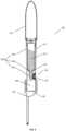
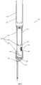
- FIG. 1shows a schematic longitudinal section of an exemplary embodiment of a device 100 for dispensing a liquid starting component 210 of a bone cement dough.
- the device 100comprises a cylinder-like housing 110 in which a glass ampoule 200 containing the liquid starting component 210 is stored.
- the glass ampoule 200comprises an ampoule body 240, an ampoule head 220 and an ampoule neck 230 between the ampoule body 240 and the ampoule head 220.
- the ampoule neck 230is received in a holder 120 of the device 100 in order to fix the glass ampoule 200 essentially firmly in the interior of the housing 110.
- the holder 120is formed as a shoulder, with the ampoule head 220 protruding on one side of the holder 120 and the ampoule body 240 resting on the other side of the holder 120.
- the glass ampoule 200is held in the housing 110 by the holder 120 in such a way that the ampoule head adjoins a deformable region 140 of the housing 110.
- the deformable region 140is made of an elastic material and has a substantially dimensionally stable pressure piece 145 on the side facing the holder 120. The pressure piece 145 thus points in the direction of the ampoule head 220.
- the latterhas an outlet 130.
- the outlet 130is designed as a tube.
- a filter element 150 in the form of a porous diskis arranged in the interior of the housing 110 between the outlet 130 and the holder 120, which can retain any fragments of the glass ampoule 200 in the device 100 after it has been opened.
- a collection area 160 for receiving the liquid starting component 210is formed between the filter element 150 and the holder 120.
- Figure 2shows the device 100 from Figure 1 with the glass ampoule 200 opened in a fluid-conducting manner.
- the preformable area 140was moved from outside the device 100 towards the holder 120 so that the pressure piece 145 was pressed against the ampoule head 220.
- This pressureexerted the structural integrity of the ampoule neck 230, which acts as the predetermined breaking point of the glass ampoule 200, exceeded and the glass ampoule 200 is opened in a fluid-conducting manner by breaking off the ampoule head 220.
- Figure 3shows the device 100 from the Figures 1 and 2 when the liquid starting component 210 is dispensed.
- the ampoule head 220After the fluid-conducting opening of the glass ampoule 200 in Figure 2 the ampoule head 220 has fallen into the collection area 160 according to gravity and was held back there by the filter element 150.
- the collection area 160is dimensioned such that the broken ampoule head 220 can be stored in it in a freely rotatable manner, which facilitates the most complete possible flow out of any remaining liquid starting component 210 that may be in the ampoule head 220.
- the liquid starting component 210has leaked out of the fluid-conducting opened glass ampoule 200, flowed through the collection area 160 and the filter element 150 according to gravity and at least partially exited the device 100 through the outlet 130.
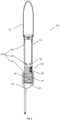
- Figure 4shows a schematic longitudinal section of another exemplary embodiment of a device 100' for dispensing a liquid starting component 210' of a bone cement dough.
- the embodiment of the device 100'largely corresponds to that described above and in the Figures 1 to 3
- the embodiment showncorresponds to the one shown in the drawing, so that in order to avoid repetition, reference is made to the above description. Modifications of a variant of the Figures 1 to 3 shown embodiment have the same reference numeral with an apostrophe.
- the device 100'has a conveying means 170 in the form of a rubber balloon.
- the conveying means 170is arranged at an axial end of the housing 110' opposite the outlet 130' and is fluidically connected to the interior of the housing 110'.
- Figure 5shows the device 100' from Figure 4 with the glass ampoule 200' opened in a fluid-conducting manner.
- the preformable area 140'was moved from outside the device 100' in the direction of the holder 120', so that the pressure piece 145' was pressed against the ampoule head 220'.
- This pressureexceeded the structural integrity of the ampoule neck 230', which acts as the predetermined breaking point of the glass ampoule 200', and the glass ampoule 200' was broken off by breaking off the ampoule head.
- 220'opened in a fluid-conducting manner.
- the liquid starting component 210'has flowed out of the fluid-conductingly opened glass ampoule 200' into the collection area 160' according to gravity, in which it initially remains without any action by a user of the device 100'. After the fluid-conducting opening of the glass ampoule 200', the ampoule head 220' has fallen into the collection area 160' according to gravity and was held back there by the filter element 150'.
- the collection area 160'is dimensioned such that the broken-off ampoule head 220' can be stored in it in a freely rotatable manner, which facilitates the most complete possible flow out of any liquid starting component 210' that may be in the ampoule head 220'.
- the deformable region 140'After the fluid-conducting opening of the glass ampoule 200', the deformable region 140' essentially returns to its original starting position due to its material properties (cf. Figure 4 ) returned.
- Figure 6shows the device 100' from the Figures 4 and 5 when the liquid starting component 210' is discharged through the outlet 130'.
- the conveying means 170was compressed from outside the device 100', which exerted a conveying pressure on the liquid starting component 210' collected in the collection area 160' (cf. Figure 5 ) and has triggered a propulsion of the same through the outlet 130'.
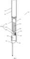
- Figure 7shows a schematic longitudinal section of another exemplary embodiment of a device 100" for dispensing a liquid starting component 210" of a bone cement dough.
- the embodiment of the device 100"largely corresponds to the devices described above and in the Figures 1 to 3 4 to 6 respectively, so that in order to avoid repetition, reference is made to the above descriptions. Modifications of a device which is different from the device shown in the Figures 1 to 3 or Figures 4 to 6 shown embodiment have the same reference numeral with two apostrophes.
- the device 100"has a conveying means 170" in the form of a piston.
- the conveying means 170is arranged at an axial end of the housing 110" opposite the outlet 130" in a cylinder 175 of the housing, forming a piston-cylinder system which is fluidically connected to the interior of the housing 110' containing the glass ampoule 220".
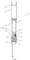
- Figure 8shows the device 100" from Figure 7 with the glass ampoule 200" opened in a fluid-conducting manner.
- the preformable area 140"was moved from outside the device 100" in the direction of the holder 120" so that the pressure piece 145" was pressed against the ampoule head 220".
- the structural integrity of the ampoule neck 230which acts as the predetermined breaking point of the glass ampoule 200
- the glass ampoule 200"was opened in a fluid-conducting manner by breaking off the ampoule head 220".
- the liquid starting component 210" flowed out of the glass ampoule 200"opened in a fluid-conducting manner into the collection area 160" according to gravity, in which it initially remains without any action by a user of the device 100".
- the ampoule head 220"has fallen into the collection area 160" under the force of gravity and has been retained there by the filter element 150".
- the collection area 160"is dimensioned such that the broken-off ampoule head 220" can be stored in it in a freely rotatable manner, which facilitates the most complete possible flow out of any remaining liquid starting component 210" in the ampoule head 220".
- the deformable region 140"After the fluid-conducting opening of the glass ampoule 200", the deformable region 140" essentially returns to its original starting position due to its material properties (cf. Figure 7 ) returned.
- Figure 9shows the device 100" from the Figures 7 and 8 when the liquid starting component 210" is discharged through the outlet 130".
- the conveying means 170was pushed back into the cylinder 175, which exerts a conveying pressure on the liquid starting component 210" collected in the collection area 160" (cf. Figure 8 ) and has triggered a propulsion of the same through the outlet 130".
- Figure 10shows a schematic longitudinal section of an exemplary mixing device 400 for providing a bone cement dough from two starting components, comprising the device 100 from the Figures 1 to 3 and a mixing unit 410 (shown only in sections).
- the embodiment of the device 100largely corresponds to the above described and in the Figures 1 to 3 illustrated embodiment, so that in order to avoid repetition, reference is made to the above description.
- the device 100is connected to the mixing unit 410 in a reversible fluid-conducting manner via the tubular outlet 130, wherein the liquid starting component 210 has already partially flowed into the mixing unit 410 after the glass ampoule 200 has been opened in a fluid-conducting manner.
- the mixing unit 410contains a bone cement powder 215 in an interior space as the second starting component of the bone cement dough.
- the mixing unit 410has a mixing element 420 in the form of a mixing rod that is reversibly movable axially in the interior of the mixing unit 410.
- the mixing element 410can prepare the bone cement dough from the starting components 210, 215 by repeatedly axially moving it in the interior of the mixing unit 410.
- Figure 11shows a schematic longitudinal section of another exemplary mixing device 400' for providing a bone cement dough from two starting components, comprising a device 100′′′ and a mixing unit 410' (shown only in sections).
- the embodiment of the device 100′′′largely corresponds to the ones described above and in the Figures 1 to 3
- the embodiment showncorresponds to the one shown in the drawing, so that in order to avoid repetition, reference is made to the above description. Modifications of a variant of the Figures 1 to 3 shown embodiment have the same reference numeral with three apostrophes.
- the device 100′′′is connected in an axial line via the outlet 130′′′ in a fluid-conducting manner to the interior of the mixing unit 410', wherein the liquid starting component 210′′′ has already partially flowed into the mixing unit 410' after a fluid-conducting opening of the glass ampoule 200′′′.
- the mixing unit 410'contains a bone cement powder 215' in an interior as the second starting component of the bone cement dough.
- the device 100′′′can be reversibly separated from the mixing unit 410' and the two starting components 210′′′, 215' can be mixed with a mixing element (not shown).
- Figure 12shows a schematic longitudinal section of another exemplary mixing device 400" for providing a bone cement dough from two starting components, comprising a device 100 ⁇ and a mixing unit 410".
- the embodiment of the device 100 ⁇largely corresponds to the ones described above and in the Figures 1 to 3
- the embodiment showncorresponds to the one shown in the drawing, so that in order to avoid repetition, reference is made to the above description. Modifications of a variant of the Figures 1 to 3 shown embodiment have the same reference numeral with four apostrophes.
- the mixing device 410"further comprises a stand element 450, via which the device 100 ⁇ and the mixing unit 410" are connected to one another in a fluid-conducting manner.
- the liquid starting component 210 ⁇flows via the outlet 130 ⁇ into a piston-cylinder system 430 of the stand element 450 and is collected there.
- the piston-cylinder systemBy actuating the piston-cylinder system by the user of the mixing device 400", the liquid starting component 210 ⁇ can be conveyed via a hose 440 into the mixing unit 410, in particular into a bone cement powder 215" stored there, in order to provide the bone cement dough by mixing using a mixing element 420 ⁇ in the form of a mixing rod.
- the mixing unit 410"can be separated from the stand element 450.
- Figure 13shows a method 500 for dispensing a liquid starting component 210, 210', 210", 210′′′, 210 ⁇ of a bone cement dough from a glass ampoule 200, 200', 200", 200′′′, 200 ⁇ by means of a device 100, 100', 100", 100′′′, 100 ⁇ according to the Figures 1 to 12 comprising steps 510 to 530 and optionally steps 540 and 550.
- a step 510at least one glass ampoule 200, 200', 200", 200′′′, 200 ⁇ is provided in the holder 120, 120', 120" of the device 100, 100', 100", 100′′′, 100 ⁇ . This can be done by a user of the device 100, 100', 100", 100′′′, 100 ⁇ or the user purchases the device 100, 100', 100", 100′′′, 100 ⁇ already with one or more prefilled glass ampoule(s) 200, 200', 200", 200′′′, 200 ⁇ .
- a pressingis carried out from outside the device 100, 100', 100", 100′′′, 100 ⁇ onto the deformable region 140, 140', 140", which is thus displaced into or further into the interior of the housing 110, 110', 110" and is ultimately pressed against the glass ampoule 200, 200', 200", 200′′′, 200 ⁇ .
- the glass ampoule 200, 200', 200", 200′′′, 200 ⁇will at least partially burst, preferably breaking off a Ampoule head 220, 220', 220" of the glass ampoule 200, 200', 200", 200′′′, 200 ⁇ , whereby the ampoule is opened in a fluid-conducting manner and the liquid starting component 210, 210', 210", 210'", 210 ⁇ can flow out into the interior of the housing 110, 110', 110".
- the deformable region 140, 140', 140"is designed such that after the pressure has been stopped, it is automatically returned at least in the direction, preferably completely, to its starting position before step 520.
- the liquid starting component 210, 210', 210", 210′′′, 210 ⁇flows into a collection area 160, 160', 160" of the device 100, 100', 100", 100′′′, 100 ⁇ and remains there until the user of the device 100, 100', 100", 100′′′, 100 ⁇ removes the liquid starting component 210, 210', 210", 210′′′, 210 ⁇ from the device 100, 100', 100", 100′′′, 100 ⁇ promotes.
- a step 530the liquid starting component 210, 210', 210", 210′′′, 210 ⁇ is conveyed through the outlet 130, 130', 130", 130′′′, 130 ⁇ of the device 100, 100', 100", 100′′′, 100 ⁇ .
- the conveyingis triggered solely by gravity.
- the conveyingis carried out by active intervention of the user of the device 100, 100', 100", 100′′′, 100 ⁇ .
- the user of the device 100, 100', 100", 100′′′, 100 ⁇actuates a conveying means 170, 170", such as a piston or a rubber balloon, to convey the liquid starting component 210, 210', 210", 210′′′, 210 ⁇ through the outlet 130, 130', 130" of the device 100, 100', 100", 100′′′, 100 ⁇ .
- a conveying means 170, 170such as a piston or a rubber balloon
- the device 100, 100', 100", 100′′′, 100 ⁇ together with a mixing unit 410', 410', 410"is part of a mixing device 400, 400', 400", so that the conveying in step 530 brings the liquid starting component 210, 210', 210", 210′′′, 210 ⁇ into the mixing unit 410', 410', 410".
- a bone cement doughis mixed in the mixing unit 410', 410', 410" of the mixing device 400', 400', 400" from the liquid starting component 210, 210', 210", 210′′′, 210 ⁇ and a bone cement powder 215, 215', 215" stored in the mixing unit 410, 410', 410".
- the mixing unit 410, 410"preferably has a mixing element 420, 420", preferably in the form of a mixing rod.
- the bone cement dough in the mixing device 400, 400', 400"is discharged directly from the latter to a desired location.
- the mixing device 400, 400', 400"preferably comprises a discharge piston which is mounted axially within the mixing unit 410, 410', 410" in order to discharge the bone cement dough provided from the mixing device 400, 400', 400", in particular from the mixing unit 410, 410', 410".
Landscapes
- Health & Medical Sciences (AREA)
- Orthopedic Medicine & Surgery (AREA)
- Surgery (AREA)
- Life Sciences & Earth Sciences (AREA)
- Engineering & Computer Science (AREA)
- Medical Informatics (AREA)
- Biomedical Technology (AREA)
- Heart & Thoracic Surgery (AREA)
- Nuclear Medicine, Radiotherapy & Molecular Imaging (AREA)
- Molecular Biology (AREA)
- Animal Behavior & Ethology (AREA)
- General Health & Medical Sciences (AREA)
- Public Health (AREA)
- Veterinary Medicine (AREA)
- Mechanical Engineering (AREA)
- Prostheses (AREA)
Abstract
Translated fromGermanDescription
Translated fromGermanDie Erfindung betrifft eine Vorrichtung zur Abgabe einer flüssigen Ausgangskomponente eines Knochenzementteigs aus einer Glasampulle, umfassend
ein Gehäuse, eine in dem Gehäuse angeordnete Halterung zur Aufnahme einer Glasampulle und einen Auslass zur Abgabe der flüssigen Ausgangskomponente aus dem Gehäuse.The invention relates to a device for dispensing a liquid starting component of a bone cement dough from a glass ampoule, comprising
a housing, a holder arranged in the housing for receiving a glass ampoule and an outlet for dispensing the liquid starting component from the housing.
Die Erfindung betrifft weiterhin eine Mischvorrichtung umfassend eine derartige Vorrichtung und eine Mischeinheit sowie ein Verfahren zu Abgabe einer flüssigen Ausgangskomponente eines Knochenzementteigs mittels einer derartigen Vorrichtung.The invention further relates to a mixing device comprising such a device and a mixing unit as well as a method for dispensing a liquid starting component of a bone cement dough by means of such a device.
Es werden erhebliche Bemühungen unternommen, Vorrichtungen und Verfahren zum Bereitstellen von Knochenzement aufzuzeigen, mittels derer Knochenzementteig einfach, zuverlässig und schnell bereitgestellt werden kann. Ein wichtiger Aspekt bei der Bereitstellung von Knochenzementteig ist die Vermeidung von Lufteinschlüssen, wie beispielsweise Gasblasen, im Knochenzement. Zu deren Vermeidung wurden eine Vielzahl von Vakuum-Zementiersystemen beschreiben, von denen exemplarisch folgende genannt sind:
Es besteht im Markt der Wunsch zur Vereinfachung der Bereitstellung von Knochenzementteig. Eine Weiterentwicklung besteht in der Entwicklung von Zementiersystemen, in denen beide Ausgangskomponenten in separaten Bereichen der Mischsysteme gelagert sind und erst unmittelbar vor der Zementierapplikation im Zementiersystem miteinander vermischt werden. Solche geschlossenen, sogenannten Full-Prepacked-Systeme, sind beispielsweise in folgenden Schriften genannt:
In den vorgenannten Full-Prepacked-Systemen erfolgt die Vermischung einer Monomerflüssigkeit mit einem Knochenzementpulver durch mechanisches Vermischen, beispielsweise mittels eines Mischstabes.In the aforementioned fully prepacked systems, a monomer liquid is mixed with a bone cement powder by mechanical mixing, for example by means of a mixing rod.
Als besondere Herausforderung gestaltet sich bei den vorgenannten Systemen insbesondere die Bereitstellung der flüssigen Ausgangskomponente, insbesondere der Monomerflüssigkeit für einen PMMA-Knochenzementteig. Häufig findet die Lagerung dieser flüssigen Ausgangskomponente in Glasampullen statt, was insbesondere aufgrund der einfachen Sterilisierbarkeit solcher Glasampullen Vorteile bietet.A particular challenge with the aforementioned systems is the provision of the liquid starting component, in particular the monomer liquid for a PMMA bone cement dough. This liquid starting component is often stored in glass ampoules, which offers advantages, particularly due to the ease with which such glass ampoules can be sterilized.
Zur Entnahme der flüssigen Ausgangskomponente aus einer handelsüblichen Glasampulle muss jedoch ein Ampullenkopf von einem Ampullenkörper der Glasampulle abgetrennt und entfernt werden. Zur Öffnung von Glasampullen in geschlossenen Vorrichtungen wurde eine Reihe von Patentschriften bekannt. Vorrichtungen zum Öffnen von Ampullen wurden beispielsweise in den Schriften
Die Schrift
Es besteht im Markt der Wunsch nach weiteren Vorrichtungen, welche ein einfaches und sicheres Öffnen von Glasampullen zur Freisetzung flüssiger Ausgangskomponenten für Knochenzementteige erlaubt.There is a desire in the market for additional devices that allow easy and safe opening of glass ampoules to release liquid starting components for bone cement doughs.
Eine Aufgabe der vorliegenden Erfindung ist es, einen oder mehrere der sich aus dem Stand der Technik ergebenen Nachteile zumindest teilweise zu überwinden.An object of the present invention is to at least partially overcome one or more of the disadvantages resulting from the prior art.
Im Speziellen basiert die Erfindung auf dem Ziel, eine Vorrichtung zur Verfügung zu stellen, welche ein einfaches, schnelles und anwendungssicheres, insbesondere verletzungsfreies, Öffnen einer oder mehrerer Glasampullen mit einer flüssigen Ausgangskomponente erlaubt. Insbesondere soll das Öffnen der Glasampulle oder der Glasampullen mit möglichst wenig Aufwand und unter Vermeidung zusätzlicher, separater Werkzeuge erfolgen. Weiterhin soll das Öffnen der Glasampulle mit möglichst wenigen Bauteilen ermöglicht sein. Weiterhin soll die flüssige Ausgangskomponente möglichst verlustfrei und schnell zum Anmischen eines Knochenzementteigs zur Verfügung stehen. Das Fördern der Monomerflüssigkeit aus der Vorrichtung zur Bereitstellung des Knochenzementteigs soll mit möglichst geringem Kraftaufwand durchführbar sein. Mittels der Vorrichtung soll es ermöglicht sein, mehrere, insbesondere zwei, Glasampullen gleichzeitig oder separat und zeitlich versetzt fluidleitend zu öffnen.In particular, the invention is based on the aim of providing a device which allows one or more glass ampoules with a liquid starting component to be opened easily, quickly and safely, in particular without causing injury. In particular, the glass ampoule or ampoule should be opened with as little effort as possible and without the need for additional, separate tools. Furthermore, the glass ampoule should be opened using as few components as possible. Furthermore, the liquid starting component should be available for mixing a bone cement dough with as little loss as possible and as quickly as possible. The monomer liquid should be able to be pumped out of the device for providing the bone cement dough with as little effort as possible. The device should make it possible to open several, in particular two, glass ampoules simultaneously or separately and at different times using fluid.
Die Vorrichtung soll mit möglichst wenigen Arbeitsschritten bedient werden können, um Fehlerquellen durch den Anwender zu minimieren.The device should be able to be operated with as few steps as possible in order to minimize sources of error by the user.
Die Vorrichtung in Kombination mit einer Mischeinheit einsetzbar sein, um einen Knochenzementteig bereitstellen zu können.The device can be used in combination with a mixing unit to prepare a bone cement dough.
Weiterhin soll eine flüssige Ausgangskomponente mittels der Vorrichtung steril und kontaminationsfrei bereitgestellt werden kann. Vorzugsweise soll ein Anwender der Vorrichtung nicht in Kontakt mit der zu öffnenden Glasampulle kommen.Furthermore, a liquid starting component should be able to be provided in a sterile and contamination-free manner using the device. Preferably, a user of the device should not come into contact with the glass ampoule to be opened.
Es ist eine weitere Aufgabe der Erfindung, eine Mischvorrichtung bereitzustellen, mittels welcher mindestens ein Teil der bereits beschriebenen Aufgaben zumindest zum Teil gelöst wird.It is a further object of the invention to provide a mixing device by means of which at least some of the objects already described are at least partially achieved.
Es ist eine weitere Aufgabe der Erfindung, ein Verfahren zur Abgabe einer flüssigen Ausgangskomponente eines Knochenzementteigs bereitzustellen, mittels dem mindestens ein Teil der bereits beschriebenen Aufgaben zumindest zum Teil gelöst wird.It is a further object of the invention to provide a method for dispensing a liquid starting component of a bone cement dough, by means of which at least some of the objects already described are at least partially achieved.
Ein Beitrag zur mindestens teilweisen Erfüllung mindestens einer der zuvor genannten Aufgaben wird durch die Merkmale der unabhängigen Ansprüche geleistet. Die abhängigen Ansprüche stellen bevorzugte Ausführungsformen bereit, die zur mindestens teilweisen Erfüllung mindestens einer der Aufgaben beitragen.A contribution to the at least partial fulfillment of at least one of the aforementioned objects is made by the features of the independent claims. The dependent claims provide preferred embodiments which contribute to the at least partial fulfillment of at least one of the objects.
Eine erste Ausführungsform der Erfindung ist eine Vorrichtung zur Abgabe einer flüssigen Ausgangskomponente eines Knochenzementteigs aus einer Glasampulle, umfassend ein Gehäuse, eine in dem Gehäuse angeordnete Halterung zur Aufnahme einer Glasampulle einen Auslass zur Abgabe der flüssigen Ausgangskomponente aus dem Gehäuse, dadurch gekennzeichnet, dass
das Gehäuse einen verformbaren Bereich aufweist, welcher ausgebildet und eingerichtet ist, gegen die in der Halterung aufgenommene Glasampulle durch Druck verschiebbar zu sein und die Glasampulle fluidleitend zu öffnen, insbesondere so, dass die flüssige Ausgangskomponente in die Vorrichtung, insbesondere in das Gehäuse ausfließbar ist.A first embodiment of the invention is a device for dispensing a liquid starting component of a bone cement dough from a glass ampoule, comprising a housing, a holder arranged in the housing for receiving a glass ampoule, an outlet for dispensing the liquid starting component from the housing, characterized in that
the housing has a deformable region which is designed and configured to be displaceable by pressure against the glass ampoule received in the holder and to open the glass ampoule in a fluid-conducting manner, in particular such that the liquid starting component can flow out into the device, in particular into the housing.
In einer Ausführungsform der Vorrichtung weist der verformbare Bereich des Gehäuses auf der der Haltung zugewandten Seite, also im Inneren des Gehäuses, ein im Wesentlichen formstabiles Druckstück auf, welches durch Druck gegen eine in der Halterung aufgenommene Glasampulle, insbesondere befüllt mit einer flüssigen Ausgangskomponente eines Knochenzementteigs, verschiebbar ist, insbesondere um diese durch diese Druckausübung fluidleitend zu öffnen. Diese Ausführungsform ist eine zweite Ausführungsform der Erfindung, welche vorzugsweise von der ersten Ausführungsform der Erfindung abhängt.In one embodiment of the device, the deformable region of the housing on the side facing the holder, i.e. inside the housing, has a substantially dimensionally stable pressure piece which can be displaced by pressure against a glass ampoule held in the holder, in particular filled with a liquid starting component of a bone cement dough, in particular in order to open it in a fluid-conducting manner by exerting this pressure. This embodiment is a second embodiment of the invention, which preferably depends on the first embodiment of the invention.
In einer Ausführungsform der Vorrichtung weist der verformbare Bereich einen Teilbereich, insbesondere einen umlaufenden Teilbereich, mit einer dünneren Wandstärke als das restliche Gehäuse auf. Diese Ausführungsform ist eine dritte Ausführungsform der Erfindung, welche vorzugsweise von der ersten oder zweiten Ausführungsform der Erfindung abhängt.In one embodiment of the device, the deformable region has a partial region, in particular a peripheral partial region, with a thinner wall thickness than the rest of the housing. This embodiment is a third embodiment of the invention, which preferably depends on the first or second embodiment of the invention.
In einer Ausführungsform der Vorrichtung ist der verformbare Bereich zumindest abschnittsweise aus einem elastischen Material ausgeformt, insbesondere um ein im Wesentlichen vollständiges Rückstellen des verformbaren Bereichs nach dem fluidleitenden Öffnen einer Glasampulle in seine Ausgangsposition zu erlauben. Diese Ausführungsform ist eine vierte Ausführungsform der Erfindung, welche vorzugsweise von einer der vorhergehenden Ausführungsformen der Erfindung abhängt.In one embodiment of the device, the deformable region is formed at least in sections from an elastic material, in particular to allow the deformable region to be returned to its initial position essentially completely after the fluid-conducting opening of a glass ampoule. This embodiment is a fourth embodiment of the invention, which preferably depends on one of the preceding embodiments of the invention.
In einer Ausführungsform der Vorrichtung ist der verformbare Bereich zwischen der Halterung und dem Auslass angeordnet. Diese Ausführungsform ist eine fünfte Ausführungsform der Erfindung, welche vorzugsweise von einer der vorhergehenden Ausführungsformen der Erfindung abhängt.In one embodiment of the device, the deformable region is arranged between the holder and the outlet. This embodiment is a fifth embodiment of the invention, which preferably depends on one of the preceding embodiments of the invention.
In einer Ausführungsform der Vorrichtung ist die Halterung eingerichtet, eine Glasampulle derart in dem Gehäuse zu lagern, dass ein Ampullenkopf der Glasampulle an den verformbarenIn one embodiment of the device, the holder is designed to store a glass ampoule in the housing in such a way that an ampoule head of the glass ampoule is attached to the deformable
Bereich des Gehäuses angrenzt. Diese Ausführungsform ist eine sechste Ausführungsform der Erfindung welche vorzugsweise von einer der vorgehenden Ausführungsformen der Erfindung abhängt.region of the housing. This embodiment is a sixth embodiment of the invention which preferably depends on one of the preceding embodiments of the invention.
In einer Ausführungsform der Vorrichtung ist zwischen der Halterung und dem Auslass ein Filterelement angeordnet, eingerichtet, um Bruchstücke einer in der Vorrichtung fluidleitend geöffneten Glasampulle in der Vorrichtung zurückzuhalten. Diese Ausführungsform ist eine siebte Ausführungsform der Erfindung, welche vorzugsweise von einer der vorhergehenden Ausführungsformen der Erfindung abhängt.In one embodiment of the device, a filter element is arranged between the holder and the outlet, designed to retain fragments of a glass ampoule opened in the device in a fluid-conducting manner. This embodiment is a seventh embodiment of the invention, which preferably depends on one of the preceding embodiments of the invention.
In einer Ausführungsform der Vorrichtung ist das Filterelement zwischen dem verformbaren Bereich und dem Auslass angeordnet. Diese Ausführungsform ist eine achte Ausführungsform der Erfindung, welche vorzugsweise von der siebten Ausführungsform der Erfindung abhängt.In one embodiment of the device, the filter element is arranged between the deformable region and the outlet. This embodiment is an eighth embodiment of the invention, which preferably depends on the seventh embodiment of the invention.
In einer Ausführungsform der Vorrichtung ist zwischen der Halterung und dem Auslass ein Sammelbereich angeordnet, um eine flüssige Ausgangskomponente aus einer in der Vorrichtung fluidleitend geöffneten Glasampulle aufzunehmen. Diese Ausführungsform ist eine neunte Ausführungsform der Erfindung, welche vorzugsweise von einer der vorhergehenden Ausführungsformen der Erfindung abhängt.In one embodiment of the device, a collection area is arranged between the holder and the outlet in order to receive a liquid starting component from a glass ampoule that is opened in a fluid-conducting manner in the device. This embodiment is a ninth embodiment of the invention, which preferably depends on one of the preceding embodiments of the invention.
In einer Ausführungsform der Vorrichtung, weist die Vorrichtung ein Fördermittel zum Fördern einer flüssigen Ausgangskomponente, insbesondere einer flüssigen Ausgangskomponente eines Knochenzementteigs, aus dem Sammelbereich durch den Auslass aus der Vorrichtung auf. Diese Ausführungsform ist eine zehnte Ausführungsform der Vorrichtung, welche vorzugsweise von der neunten Ausführungsform der Erfindung abhängt.In one embodiment of the device, the device has a conveying means for conveying a liquid starting component, in particular a liquid starting component of a bone cement dough, from the collection area through the outlet from the device. This embodiment is a tenth embodiment of the device, which preferably depends on the ninth embodiment of the invention.
In einer Ausführungsform der Vorrichtung ist das Fördermittel ein Gummiballon. Diese Ausführungsform ist eine elfte Ausführungsform der Erfindung, welche vorzugsweise von der zehnten Ausführungsform der Erfindung abhängt.In one embodiment of the device, the conveying means is a rubber balloon. This embodiment is an eleventh embodiment of the invention, which preferably depends on the tenth embodiment of the invention.
In einer Ausführungsform der Vorrichtung ist das Fördermittel ein Kolben. Diese Ausführungsform ist eine zwölfte Ausführungsform der Erfindung, welche vorzugsweise von der zehnten Ausführungsform der Erfindung abhängt.In one embodiment of the device, the conveying means is a piston. This embodiment is a twelfth embodiment of the invention, which preferably depends on the tenth embodiment of the invention.
Eine dreizehnte Ausführungsform der Erfindung ist eine Mischvorrichtung zum Bereitstellen eines Knochenzementteigs aus zwei Ausgangskomponenten, umfassend eine Vorrichtung nach einer der ersten bis zwölften Ausführungsform der Erfindung und eine Mischeinheit, wobei die Mischeinheit ausgebildet und eingerichtet ist, aus den zwei Ausgangkomponenten den Knochenzementteig anzumischen, insbesondere anzumischen und somit bereitzustellen.A thirteenth embodiment of the invention is a mixing device for providing a bone cement dough from two starting components, comprising a device according to one of the first to twelfth embodiments of the invention and a mixing unit, wherein the mixing unit is designed and arranged to prepare a bone cement dough from the two To mix the starting components of the bone cement dough, in particular to mix and thus provide.
In einer Ausführungsform der Mischvorrichtung enthält die Vorrichtung eine Glasampulle mit einer flüssigen Ausgangskomponente als erste Ausgangskomponente des Knochenzementteigs und die Mischeinheit ein Knochenzementpulver als zweite Ausgangskomponente des Knochenzementteigs. Diese Ausführungsform ist eine vierzehnte Ausführungsform der Erfindung, welche vorzugsweise von der dreizehnten Ausführungsform der Erfindung abhängt.In one embodiment of the mixing device, the device contains a glass ampoule with a liquid starting component as the first starting component of the bone cement dough and the mixing unit contains a bone cement powder as the second starting component of the bone cement dough. This embodiment is a fourteenth embodiment of the invention, which preferably depends on the thirteenth embodiment of the invention.
Eine fünfzehnte Ausführungsform der Erfindung ist ein Verfahren zur Abgabe einer flüssigen Ausgangskomponente eines Knochenzementteigs aus einer Glasampulle mittels einer Vorrichtung nach einer der ersten bis zwölften Ausführungsform der Erfindung, umfassend die folgenden Schritte:
- a. Bereitstellen einer Glasampulle enthaltend die flüssige Ausgangskomponente in der Halterung;
- b. Fluidleitendes Öffnen der Glasampulle durch Druckausüben auf den verformbaren Bereich, so dass dieser gegen die Glasampulle gepresst wird;
- c. Fördern der flüssigen Ausgangskomponente durch den Auslass aus der Vorrichtung.
- a. Providing a glass ampoule containing the liquid starting component in the holder;
- b. Fluid-conducting opening of the glass ampoule by exerting pressure on the deformable area so that it is pressed against the glass ampoule;
- c. Conveying the liquid starting component through the outlet from the device.
In der vorliegenden Beschreibung beinhalten Bereichsangaben auch die als Grenzen genannten Werte. Eine Angabe der Art "im Bereich von X bis Y" in Bezug auf eine Größe A bedeutet folglich, dass A die Werte X, Y und Werte zwischen X und Y annehmen kann. Einseitig begrenzte Bereiche der Art "bis zu Y" für eine Größe A bedeuten entsprechend als Wert Y und kleiner als Y.In the present description, ranges also include the values referred to as limits. A specification of the type "in the range from X to Y" in relation to a size A therefore means that A can assume the values X, Y and values between X and Y. Unilaterally limited ranges of the type "up to Y" for a size A correspondingly mean the value Y and less than Y.
Einige der beschriebenen Merkmale sind mit dem Begriff "im Wesentlichen" verknüpft. Der Begriff "im Wesentlichen" ist so zu verstehen, dass unter realen Bedingungen und Fertigungstechniken eine mathematisch exakte Auslegung von Begrifflichkeiten wie "Überlagerung", "senkrecht", "Durchmesser" oder "Parallelität" nie exakt, sondern nur innerhalb gewisser fertigungstechnischer Fehlertoleranzen gegeben sein kann. Beispielsweise schließen "im Wesentlichen senkrechte Achsen" einen Winkel von 85 Grad bis 95 Grad zueinander ein und "im Wesentlichen gleiche Volumen" umfassen eine Abweichung von bis zu 5 Volumen-%. Eine "im Wesentlichen aus Kunststoff bestehende Vorrichtung" umfasst beispielsweise einen Kunststoffanteil von ≥95 bis ≤100 Gewichts-%. Eine "im Wesentlichen vollständige Befüllung eines Volumens B" umfasst beispielsweise eine Befüllung von ≥95 bis ≤100 Volumen-% des Gesamtvolumens von B.Some of the features described are linked to the term "essentially". The term "essentially" is to be understood in such a way that under real conditions and manufacturing techniques, a mathematically exact interpretation of terms such as "superposition", "vertical", "diameter" or "parallelism" can never be exact, but only within certain manufacturing error tolerances. For example, "essentially vertical axes" enclose an angle of 85 degrees to 95 degrees to one another and "essentially equal volumes" include a deviation of up to 5% by volume. A "device consisting essentially of plastic", for example, comprises a plastic content of ≥95 to ≤100% by weight. A "essentially complete filling of a volume B", for example, comprises a filling of ≥95 to ≤100% by volume of the total volume of B.
Begriffe wie "proximal" und "distal" dienen lediglich der Bezeichnung der räumlich gegenüberliegenden Enden der Vorrichtung oder anderer Struktureinheiten der Vorrichtung und erlauben keinen Rückschluss auf die Orientierung in Bezug zu einem menschlichen Körper, beispielsweise eines Anwenders der Vorrichtung. "Distal zu ..." und "proximal zu..." oder ähnliche Formulierungen drücken entsprechend lediglich die räumliche Anordnung zweier Struktureinheiten der Vorrichtung zueinander aus.Terms such as "proximal" and "distal" are used only to designate the spatially opposite ends of the device or other structural units of the device and do not allow any conclusions to be drawn about the orientation in relation to a human body, for example a user of the device. "Distal to ..." and "proximal to ..." or similar formulations accordingly only express the spatial arrangement of two structural units of the device in relation to one another.
Ein erster Gegenstand der Erfindung betrifft eine Vorrichtung zur Abgabe einer flüssigen Ausgangskomponente eines Knochenzementteigs aus einer Glasampulle, umfassend ein Gehäuse, eine in dem Gehäuse angeordnete Halterung zur Aufnahme einer Glasampulle, einen Auslass zur Abgabe der flüssigen Ausgangskomponente aus dem Gehäuse, dadurch gekennzeichnet, dass
das Gehäuse einen verformbaren Bereich aufweist, welcher ausgebildet und eingerichtet ist, gegen die in der Halterung aufgenommene Glasampulle durch Druck verschiebbar zu sein und die Glasampulle fluidleitend zu öffnen, insbesondere so, dass die flüssige Ausgangskomponente in die Vorrichtung, insbesondere in das Gehäuse ausfließbar ist.A first subject of the invention relates to a device for dispensing a liquid starting component of a bone cement dough from a glass ampoule, comprising a housing, a holder arranged in the housing for receiving a glass ampoule, an outlet for dispensing the liquid starting component from the housing, characterized in that
the housing has a deformable region which is designed and configured to be displaceable by pressure against the glass ampoule received in the holder and to open the glass ampoule in a fluid-conducting manner, in particular such that the liquid starting component can flow out into the device, in particular into the housing.
Die Vorrichtung dient insbesondere einem fluidleitenden Öffnen einer oder mehreren in der Vorrichtung bereitgestellten Glasampulle beziehungsweise Glasampullen. Dazu weist das Gehäuse der Vorrichtung, insbesondere eine Gehäusewand des Gehäuses, einen verformbaren Bereich auf, welcher in ein Inneres des Gehäuses verschiebbar und somit gegen eine dort gelagerte Glasampulle pressbar ausgestaltet ist. Über den verformbaren Bereich kann somit von außerhalb der Vorrichtung, insbesondere durch einen Anwender der Vorrichtung, ein derart hoher Druck auf die in der Vorrichtung gelagerte Glasampulle ausgeübt werden, dass diese zumindest abschnittweise aufbricht und eine in der Glasampulle gelagerte flüssige Ausgangskomponente in das Gehäuse ausfließen kann. Dies erlaubt ein einfaches und schnelles fluidleitendes Öffnen einer Glasampulle ohne zusätzliche Hilfselemente. Zudem verringert sich durch ein derartiges Öffnen ohne direkten Kontakt mit der Glasampulle eine Verletzungsgefahr für den Anwender des herzustellenden Knochenzementteigs, insbesondere beim fluidleitenden Öffnen der Glasampulle. Vorzugsweise ist die Vorrichtung eingerichtet, die Glasampulle unter sterilen Bedingungen fluidleitend zu Öffnen und zum Anmischen des Knochenzementteigs bereitzustellen. Vorzugsweise ist das Gehäuse zur sterilen Lagerung einer Glasampulle eingerichtet. Vorzugsweise ist hierfür das Gehäuse im Wesentlichen von der Umgebung der Vorrichtung, vorzugsweise hermetisch, abgeschlossen.The device is used in particular for fluid-conducting opening of one or more glass ampoule or glass ampoules provided in the device. For this purpose, the housing of the device, in particular a housing wall of the housing, has a deformable area which is designed to be displaceable into an interior of the housing and thus to be pressed against a glass ampoule stored there. Via the deformable area, such a high pressure can be exerted on the glass ampoule stored in the device from outside the device, in particular by a user of the device, that it breaks open at least in sections and a liquid starting component stored in the glass ampoule can flow out into the housing. This allows a glass ampoule to be opened simply and quickly in a fluid-conducting manner without additional auxiliary elements. In addition, such an opening without direct contact with the glass ampoule reduces the risk of injury to the user of the bone cement dough to be produced, in particular when opening the glass ampoule in a fluid-conducting manner. Preferably, the device is designed to open the glass ampoule in a fluid-conducting manner under sterile conditions and to make it available for mixing the bone cement dough. Preferably, the housing is designed for sterile storage of a glass ampoule. Preferably, for this purpose, the housing is essentially sealed off from the environment of the device, preferably hermetically.
Das Gehäuse der Vorrichtung dient der Aufnahme und Lagerung mindestens einer Glasampulle. Vorzugsweise sind in dem Gehäuse mehrere, vorzugsweise zwei, Glasampullen, vorzugsweise nebeneinander, insbesondere steril, transportsicher und vorzugsweise hermetisch von der Außenwelt, lagerbar.The housing of the device serves to accommodate and store at least one glass ampoule. Preferably, several, preferably two, glass ampoules can be stored in the housing, preferably next to one another, in particular sterile, safe for transport and preferably hermetically sealed from the outside world.
Innerhalb des Gehäuses ist eine Halterung angeordnet, um mindestens eine, vorzugsweise zwei, Glasampullen aufzunehmen. Vorzugsweise umschließt die Halterung die mindestens eine Glasampulle zumindest abschnittsweise, so dass diese transportsicher in der Vorrichtung lagerbar ist. Die Halterung dient weiterhin einem Fixieren der mindestens einen Glasampulle, so dass diese mittels des verformbaren Bereichs durch Druckausübung fluidleitend zu öffnen ist.A holder is arranged inside the housing to accommodate at least one, preferably two, glass ampoules. The holder preferably encloses the at least one glass ampoule at least in sections so that it can be stored in the device in a way that is safe for transport. The holder also serves to fix the at least one glass ampoule so that it can be opened in a fluid-conducting manner by applying pressure via the deformable area.
Um eine flüssige Ausgangskomponente aus einer Glasampulle zum Anmischen eines Knochenzementteigs bereitzustellen, weist die Vorrichtung einen fluidleitenden Auslass, wie beispielsweise eine Durchführung, wie einen Schlauch oder ein Rohr, auf. Durch den Auslass kann die flüssige Ausgangskomponente nach dem fluidleitenden Öffnen der Glasampulle aus der Vorrichtung an eine gewünschte Stelle, insbesondere zum Anmischen eines Knochenzementteigs, bereitgestellt werden. Der Auslass kann an unterschiedlichen Stellen der Vorrichtung angeordnet sein, wobei es bevorzugt ist, diesen an einem distalen Ende, insbesondere an einem distalen Ende der Längsachse der Vorrichtung, anzuordnen.In order to provide a liquid starting component from a glass ampoule for mixing a bone cement dough, the device has a fluid-conducting outlet, such as a passage such as a hose or a tube. After the glass ampoule has been opened in a fluid-conducting manner, the liquid starting component can be provided from the device to a desired location through the outlet, in particular for mixing a bone cement dough. The outlet can be arranged at different locations on the device, whereby it is preferred to arrange it at a distal end, in particular at a distal end of the longitudinal axis of the device.
Um ein fluidleitendes Öffnen einer in der Halterung gelagerten Glasampulle zu ermöglichen, kann der verformbare Bereich auf unterschiedliche Weise ausgestaltet sein, solange der verformbare Bereich in das Innere des Gehäuses derart einschiebbar ausgestaltet ist, dass über diesen von außerhalb der Vorrichtung Druck auf die Glasampulle ausgeübt werden kann, um die Glasampulle fluidleitend zu öffnen.In order to enable a fluid-conducting opening of a glass ampoule stored in the holder, the deformable region can be designed in different ways, as long as the deformable region is designed to be insertable into the interior of the housing in such a way that pressure can be exerted on the glass ampoule from outside the device in order to open the glass ampoule in a fluid-conducting manner.
Beispielsweise kann der verformbare Bereich vollständig aus einem verformbaren Material ausgeformt sein.For example, the deformable region may be formed entirely from a deformable material.
In einer bevorzugten Ausführungsform können in der Vorrichtung mehr als eine Glasampulle in der Halterung aufgenommen werden und die Vorrichtung weist für jede dieser aufnehmbaren Glasampullen einen separaten verformbaren Bereich auf, so dass jeweils ein verformbarer Bereich genau eine Glasampulle fluidleitend öffnen kann. Dies erlaubt ein bedarfsgerechtes fluidleitendes Öffnen von Glasampullen. Beispielsweise weist die Vorrichtung in einer Ausführungsform eine Halterung für zwei Glasampullen und zwei separate verformbare Bereiche auf. Dabei sind die zwei verformbaren Bereiche so ausgestaltet, dass jeder der verformbaren Bereiche eine der zwei Glasampullen fluidleitend gezielt öffnen kann.In a preferred embodiment, more than one glass ampoule can be accommodated in the holder in the device and the device has a separate deformable area for each of these glass ampoule that can be accommodated, so that each deformable area can open exactly one glass ampoule in a fluid-conducting manner. This allows glass ampoules to be opened in a fluid-conducting manner as required. For example, in one embodiment, the device has a holder for two glass ampoules and two separate deformable areas. The two deformable areas are designed in such a way that each of the deformable areas can specifically open one of the two glass ampoules in a fluid-conducting manner.
Eine Ausführungsform der Vorrichtung ist dadurch gekennzeichnet, dass der verformbare Bereich des Gehäuses zumindest auf der der Halterung zugewandten Seite, also auf der Innenseite des Gehäuses, ein im Wesentlichen formstabiles Druckstück aufweist, welches durch Druck, insbesondere gemeinsam mit dem verformbaren Bereich, gegen eine in der Halterung aufgenommene Glasampulle verschiebbar ist, um diese fluidleitend zu öffnen. Das Druckstück ist im Wesentlichen formstabil, also während der regulären Nutzung der Vorrichtung im Wesentlichen nicht durch den Anwender verformbar, was ein fluidleitendes Öffnen einer in der Halterung angeordneten Glasampulle durch Druckausübung auf den verformbaren Bereich erleichtert. Dazu ist das Druckstück so angeordnet, dass es spätestens unter Druckausübung auf den verformbaren Bereich in direkten Kontakt mit der zu öffnenden Glasampulle kommt. Weiterhin ist ein Anwender der Vorrichtung durch das Druckstück besser gegen mögliche Glasbruchstücke, welche beim fluidleitenden Öffnen einer Glasampulle entstehen können, geschützt. In einer Variante ist das Druckstück dabei zumindest an der der Halterung zugewandten Seite eines verformbaren Materials befestigt, beispielsweise geklebt oder form- und/oder kraftschlüssig in einer Einfassung befestigt, um einen verformbaren Bereich gemäß dieser Ausführungsform auszubilden. In einer weiteren Variante besteht der verformbare Bereich mittig aus dem Druckstück, welches umlaufend von einem verformbaren Material umgeben ist, um einen verformbaren Bereich gemäß dieser Ausführungsform auszubilden.An embodiment of the device is characterized in that the deformable region of the housing has, at least on the side facing the holder, i.e. on the inside of the housing, a substantially dimensionally stable pressure piece which can be displaced by pressure, in particular together with the deformable region, against a glass ampoule accommodated in the holder in order to open it in a fluid-conducting manner. The pressure piece is substantially dimensionally stable, i.e. during regular use of the device it is essentially not deformable by the user, which facilitates a fluid-conducting opening of a glass ampoule arranged in the holder by exerting pressure on the deformable region. For this purpose, the pressure piece is arranged in such a way that it can be deformed at the latest when pressure is exerted. on the deformable area comes into direct contact with the glass ampoule to be opened. Furthermore, the pressure piece provides a user of the device with better protection against possible glass fragments that can arise when a glass ampoule is opened using fluid. In one variant, the pressure piece is attached to at least the side of a deformable material facing the holder, for example glued or positively and/or non-positively attached in a frame, in order to form a deformable area according to this embodiment. In a further variant, the deformable area consists centrally of the pressure piece, which is surrounded all around by a deformable material in order to form a deformable area according to this embodiment.
Der verformbare Bereich kann aus einem leichter zu verformenden Material als das restliche Gehäuse oder aus dem gleichen Material wie das restliche Gehäuse ausgeformt sein.The deformable region may be formed from a material that is easier to deform than the rest of the housing or from the same material as the rest of the housing.
Eine Ausführungsform der Vorrichtung ist dadurch gekennzeichnet, dass der verformbare Bereich einen Teilbereich, insbesondere einen umlaufenden Teilbereich, mit einer dünneren Wandstärke als das restliche Gehäuse aufweist. Dies erlaubt die Fertigung des Gehäuses aus einem einheitlichen Material, wobei der verformbare Bereich leichter verformbar ist als der Rest des Gehäuses. In einer Variante weist das restliche Gehäuse eine derartige Wandstärke auf, welche, obwohl das Material an sich verformbar ist, im Wesentlichen unverformbar für einen Anwender der Vorrichtung ausgestaltet. In einer Variante weist der verformbare Bereich am umlaufenden Teilbereich, also an dem außenliegenden Teilbereich, welcher an das restliche Gehäuse angrenzt, eine dünnere Wandstärke auf als in seinem mittigen Teilbereich auf. Dabei kann der mittige Teilbereich als ein im Wesentlichen formstabiles Druckstück ausgestaltet sein. Vorzugsweise umfasst das Gehäuse samt verformbaren Bereich ein gummielastisches Material mit einer Shore Härte A von größer 60, insbesondere besteht das Gehäuse samt dem verformbaren Bereich aus einem derartigen Material. Beispiele für derartige Materialien sind biokompatible Elastomere, wie beispielsweise Silikon oder EPDM.One embodiment of the device is characterized in that the deformable region has a partial region, in particular a peripheral partial region, with a thinner wall thickness than the rest of the housing. This allows the housing to be manufactured from a uniform material, whereby the deformable region is easier to deform than the rest of the housing. In one variant, the rest of the housing has a wall thickness which, although the material is deformable in itself, is essentially non-deformable for a user of the device. In one variant, the deformable region has a thinner wall thickness in the peripheral partial region, i.e. in the outer partial region which borders the rest of the housing, than in its central partial region. The central partial region can be designed as an essentially dimensionally stable pressure piece. The housing including the deformable region preferably comprises a rubber-elastic material with a Shore A hardness of greater than 60, in particular the housing including the deformable region consists of such a material. Examples of such materials are biocompatible elastomers such as silicone or EPDM.
Eine Ausführungsform der Vorrichtung ist dadurch gekennzeichnet, dass der verformbare Bereich am umlaufenden Teilbereich eine faltenartige, insbesondere akkordeonartige, Struktur aufweist, welche ein Einschieben in Richtung der Halterung erlaubt. Dabei findet ein zumindest teilweises Entfalten dieser Falten statt.An embodiment of the device is characterized in that the deformable region has a fold-like, in particular accordion-like, structure on the peripheral portion, which allows insertion in the direction of the holder. In the process, these folds are at least partially unfolded.
Eine Ausführungsform der Vorrichtung ist dadurch gekennzeichnet, dass der verformbare Bereich zumindest abschnittsweise, vorzugsweise zumindest am umlaufenden Teilbereich, aus einem elastischen Material ausgeformt ist. Dies erlaubt ein selbstständiges Rückstellen des verformbaren Bereichs in seine Ausgangsstellung, oder zumindest in Richtung seiner Ausgangsstellung, nach einem fluidleitenden Öffnen einer in der Halterung gelagerten Glasampulle. So wird sichergestellt, dass der verformbare Bereich während der weiteren Verwendung der Vorrichtung, insbesondere beim Ausfließen oder Fördern der in der Glasampulle gelagerten flüssigen Ausgangskomponente, nicht störend im Inneren des Gehäuses verbleibt.An embodiment of the device is characterized in that the deformable region consists at least in sections, preferably at least in the peripheral part, of an elastic material. This allows the deformable area to return to its original position, or at least in the direction of its original position, after a glass ampoule stored in the holder has been opened in a fluid-conducting manner. This ensures that the deformable area does not remain in the interior of the housing during further use of the device, in particular when the liquid starting component stored in the glass ampoule flows out or is conveyed.
Der vorformbare Bereich kann an unterschiedlichen Stellen entlang der Längsachse des Gehäuses angeordnet sein.The preformable area can be arranged at different locations along the longitudinal axis of the housing.
Eine Ausführungsform der Vorrichtung ist dadurch gekennzeichnet, dass der verformbare Bereich räumlich zwischen der Halterung und dem Auslass angeordnet ist. So kann eine in der Halterung gelagerte Glasampulle in räumlicher Nähe des Auslasses fluidleitend geöffnet werden, ohne dass die flüssige Ausgangskomponente durch oder an der Halterung vorbei in Richtung des Auslasses fließen muss. Dies erleichtert ein im Wesentlichen vollständiges Fördern der flüssigen Ausgangskomponente aus der Vorrichtung.One embodiment of the device is characterized in that the deformable region is arranged spatially between the holder and the outlet. In this way, a glass ampoule stored in the holder can be opened in a fluid-conducting manner in the spatial vicinity of the outlet without the liquid starting component having to flow through or past the holder in the direction of the outlet. This facilitates an essentially complete conveyance of the liquid starting component out of the device.
Die erfindungsgemäße Vorrichtung ist insbesondere für Glasampullen ausgelegt, welche einen Ampullenkörper, einen Ampullenkopf und einen Ampullenhals, welcher den Ampullenkörper und den Ampullenkopf strukturell miteinander verbindet, aufweisen. Der Ampullenkörper stellt einen Großteil der Glasampulle dar und dient zur Aufnahme zumindest eines Großteils der flüssigen Ausgangskomponente in seinem Inneren. Der Ampullenhals weist einen im Gegensatz zum Ampullenkörper verringerten Außendurchmesser auf und dient als Sollbruchstelle zum Abbrechen des im Vergleich zum Ampullenkörpers kleinen Ampullenkopfes. Dem Fachmann sind derartige Glasampullen bestens bekannt.The device according to the invention is designed in particular for glass ampoules which have an ampoule body, an ampoule head and an ampoule neck which structurally connects the ampoule body and the ampoule head to one another. The ampoule body represents a large part of the glass ampoule and serves to hold at least a large part of the liquid starting component in its interior. The ampoule neck has a smaller outer diameter than the ampoule body and serves as a predetermined breaking point for breaking off the ampoule head, which is small compared to the ampoule body. Such glass ampoules are very well known to those skilled in the art.
Vorzugsweise ist die Halterung zur Aufnahme eines Ampullenhalses einer Glasampulle eingerichtet. Beispielsweise ist dazu die Halterung als eine Schulter, insbesondere ringartige Schulter, ausgeformt, wobei der Ampullenhals in einer Durchführung der Halterung angeordnet ist, der Ampullenkörper auf einer Seite der Schulter aufliegt und der Ampullenkopf auf der anderen Seite aus der Halterung herausragt.Preferably, the holder is designed to receive an ampoule neck of a glass ampoule. For example, the holder is formed as a shoulder, in particular a ring-like shoulder, wherein the ampoule neck is arranged in a passage of the holder, the ampoule body rests on one side of the shoulder and the ampoule head protrudes from the holder on the other side.
Eine Ausführungsform der Vorrichtung ist dadurch gekennzeichnet, dass die Halterung eingerichtet ist, eine Glasampulle derart in dem Gehäuse zu lagern, dass ein Ampullenkopf der Glasampulle an den verformbaren Bereich des Gehäuses angrenzt. So kann der verformbare Bereich durch Druckausübung von außerhalb direkt auf den Ampullenkopf gepresst werden, welcher aufgrund der Sollbruchstelle der Glasampulle, dem Ampullenhals, erleichtert abbricht und so ein Ausfließen der in der Glasampulle gelagerten flüssigen Ausgangskomponente erlaubt. Diese Ausführungsform der Vorrichtung erleichtert einem Anwender das fluidleitende Öffnen einer derartigen Glasampulle.An embodiment of the device is characterized in that the holder is designed to store a glass ampoule in the housing in such a way that an ampoule head of the Glass ampoule borders the deformable area of the housing. The deformable area can be pressed directly onto the ampoule head by applying pressure from the outside, which breaks off more easily due to the glass ampoule's predetermined breaking point, the ampoule neck, and thus allows the liquid starting component stored in the glass ampoule to flow out. This embodiment of the device makes it easier for a user to open such a glass ampoule using fluid.
Eine Ausführungsform der Vorrichtung ist dadurch gekennzeichnet, dass zwischen der Halterung und dem Auslass ein Filterelement angeordnet ist, eingerichtet, insbesondere eingerichtet und ausgestaltet, um Bruchstücke einer in der Vorrichtung fluidleitend geöffneten Glasampulle in der Vorrichtung zurückzuhalten. Das Filterelement verhindert somit eine Kontamination des anzumischenden Knochenzementteigs mit Bruchstücken einer Glasampulle. Um dies zu bewerkstelligen, wird eine Glasampulle vorzugsweise proximal des Filterelements angeordnet, während der Auslass distal des Filterelements angeordnet ist.An embodiment of the device is characterized in that a filter element is arranged between the holder and the outlet, designed, in particular designed and configured, to retain fragments of a glass ampoule that is opened in the device in a fluid-conducting manner in the device. The filter element thus prevents contamination of the bone cement dough to be mixed with fragments of a glass ampoule. To achieve this, a glass ampoule is preferably arranged proximal to the filter element, while the outlet is arranged distal to the filter element.
Das Filterelement kann beispielsweise ein Sieb, ein poröses Material oder eine Membran umfassen oder daraus bestehen. Vorzugsweise ist das Filterelement eine Porenscheibe, beispielsweise aus gesinterten Polypropylenpartikeln, aus gesinterten oder verpressten Polyethylenfasern, aus Cellulosefilz oder aus Pappe.The filter element can, for example, comprise or consist of a sieve, a porous material or a membrane. The filter element is preferably a porous disk, for example made of sintered polypropylene particles, sintered or pressed polyethylene fibers, cellulose felt or cardboard.
Eine Ausführungsform der Vorrichtung ist dadurch gekennzeichnet, dass das Filterelement zwischen dem verformbaren Bereich und dem Auslass angeordnet ist. Somit können Bruchstücke, welche durch fluidleitendes Öffnen einer Glasampulle entstehen können, wie beispielsweise ein abgebrochener Ampullenkopf, durch das Filterelement innerhalb der Vorrichtung zurückgehalten werden und gelangen nicht durch den Auslass aus der Vorrichtung.One embodiment of the device is characterized in that the filter element is arranged between the deformable region and the outlet. Thus, fragments that can arise from fluid-conducting opening of a glass ampoule, such as a broken ampoule head, can be retained by the filter element within the device and do not escape from the device through the outlet.
Die Vorrichtung kann so ausgestaltet sein, dass eine flüssige Ausgangskomponente nach einem fluidleitenden Öffnen einer Glasampulle innerhalb der Vorrichtung direkt aus dieser herausfließen kann. Um eine verbesserte Kontrolle über den Zeitpunkt des Ausfließens der flüssigen Ausgangskomponente aus der Vorrichtung zu erlangen, kann es sinnvoll sein, die aus der Glasampulle ausfließende flüssige Ausgangskomponente zuerst innerhalb der Vorrichtung zu belassen und diese erst durch aktives Eingreifen aus dieser hinauszubefördern.The device can be designed in such a way that a liquid starting component can flow directly out of a glass ampoule within the device after the glass ampoule has been opened in a fluid-conducting manner. In order to achieve improved control over the point in time at which the liquid starting component flows out of the device, it can be useful to initially leave the liquid starting component flowing out of the glass ampoule within the device and only to transport it out of the device by actively intervening.
Um dies zu bewerkstelligen, ist eine Ausführungsform der Vorrichtung dadurch gekennzeichnet, dass zwischen der Halterung und dem Auslass ein Sammelbereich angeordnet ist, um eine flüssige Ausgangskomponente aus einer oder mehrerer in der Vorrichtung fluidleitend geöffneten Glasampulle beziehungsweise Glasampullen, vorzugsweise vollständig, aufzunehmen. Das Filterelement kann dabei proximal, also in Richtung der Glasampulle, distal oder auch mittig innerhalb des Sammelbereichs angeordnet sein. Vorzugsweise ist der Sammelbereich so ausgestaltet, dass neben der flüssigen Ausgangskomponente auch der oder die Ampullenköpfe der Glasampulle beziehungsweise Glasampullen aufgenommen werden können. Vorzugsweise ist der Sammelbereich dabei so dimensioniert, dass ein Ampullenkopf frei rotierbar im Sammelbereich lagerbar ist, so dass sich eventuell im Ampullenkopf befindliche flüssige Ausgangskomponente durch eine Drehung desselben ausfließen kann. Dies erleichtert ein im Wesentlichen vollständiges Fördern einer flüssigen Ausgangskomponente aus der Vorrichtung.To achieve this, an embodiment of the device is characterized in that a collection area is arranged between the holder and the outlet in order to collect a liquid starting component from one or more fluid-conducting opened glass ampoule or glass ampoules, preferably completely. The filter element can be arranged proximally, i.e. in the direction of the glass ampoule, distally or centrally within the collection area. The collection area is preferably designed such that in addition to the liquid starting component, the ampoule head(s) of the glass ampoule or glass ampoules can also be accommodated. The collection area is preferably dimensioned such that an ampoule head can be freely rotated in the collection area, so that any liquid starting component located in the ampoule head can flow out by rotating it. This facilitates essentially complete conveyance of a liquid starting component from the device.
Ein Fördern einer flüssigen Ausgangskomponente aus der Vorrichtung, vorzugsweise aus dem Sammelbereich der Vorrichtung, durch den Auslass kann auf unterschiedlichen Weisen ausgelöst werden. Beispielsweise kann ein Fördern unter ausschließlicher Einwirkung der Schwerkraft ermöglicht sein. Dazu kann es notwendig sein, die Vorrichtung geeignet räumlich auszurichten, beispielsweise mit dem Auslass in Richtung des Bodens weisend.A conveying of a liquid starting component from the device, preferably from the collection area of the device, through the outlet can be triggered in different ways. For example, conveying under the exclusive influence of gravity can be made possible. For this purpose, it may be necessary to align the device in a suitable spatial manner, for example with the outlet pointing towards the floor.
Eine Ausführungsform der Vorrichtung ist dadurch gekennzeichnet, dass die Vorrichtung ein Fördermittel zum Fördern einer flüssigen Ausgangskomponente aus dem Sammelbereich durch den Auslass aus der Vorrichtung aufweist. Das Fördermittel dient dem aktiven Auslösen eines Fördervorgangs der flüssigen Ausgangskomponente durch einen Anwender der Vorrichtung.An embodiment of the device is characterized in that the device has a conveying means for conveying a liquid starting component from the collection area through the outlet from the device. The conveying means serves to actively trigger a conveying process of the liquid starting component by a user of the device.
Eine Ausführungsform der Vorrichtung ist dadurch gekennzeichnet, dass das Fördermittel ein Gummiballon ist. Ein Gummiballon es ein im weitesten Sinne blasenartiger Hohlkörper aus einem verformbaren, insbesondere elastischen, insbesondere reversibel elastischen, Material, mit einer fluidleitenden Öffnung. Um als Fördermittel zu fungieren, kann der Gummiballon über die fluidleitende Öffnung fluidleitend mit dem Inneren des Gehäuses verbunden sein oder verbunden werden, so dass durch ein Zusammendrücken des Gummiballons ein Förderdruck auf eine im Inneren des Gehäuses lagernde flüssige Ausgangskomponente ausübbar ist. Durch den Förderdruck kann die flüssige Ausgangskomponente aus dem Auslass der Vorrichtung gefördert werden. Zum Fördern der flüssigen Ausgangskomponente kann es erforderlich sein, den Gummiballon ein- oder mehrmalig zusammenzudrücken.One embodiment of the device is characterized in that the conveying means is a rubber balloon. A rubber balloon is, in the broadest sense, a bubble-like hollow body made of a deformable, in particular elastic, in particular reversibly elastic, material, with a fluid-conducting opening. In order to function as a conveying means, the rubber balloon can be connected to the interior of the housing via the fluid-conducting opening in a fluid-conducting manner, so that by compressing the rubber balloon, a conveying pressure can be exerted on a liquid starting component stored inside the housing. The liquid starting component can be conveyed out of the outlet of the device by the conveying pressure. To convey the liquid starting component, it may be necessary to compress the rubber balloon once or several times.
Vorzugsweise befindet sich der Gummiballon an einem dem Auslass entgegengesetztem Ende der Vorrichtung und ist dort fluidleitend mit dem Inneren des Gehäuses verbunden.Preferably, the rubber balloon is located at an end of the device opposite the outlet and is fluidically connected to the interior of the housing.
Eine Ausführungsform der Vorrichtung ist dadurch gekennzeichnet, dass das Fördermittel ein Kolben ist. Zum Fördern einer flüssigen Ausgangskomponente aus der Vorrichtung wirkt der Kolben mit einem Zylinder derart zusammen, dass ein Einschieben des Kolbens in den Zylinder einen Förderdruck auf eine im Inneren des Gehäuses lagernde flüssige Ausgangskomponente ausübt. Durch den Förderdruck kann die flüssige Ausgangskomponente aus dem Auslass der Vorrichtung gefördert werden.One embodiment of the device is characterized in that the conveying means is a piston. To convey a liquid starting component out of the device, the piston interacts with a cylinder in such a way that pushing the piston into the cylinder exerts a conveying pressure on a liquid starting component stored inside the housing. The liquid starting component can be conveyed out of the outlet of the device by the conveying pressure.
In einer Variante dieser Ausführungsform fungiert das Gehäuse als Zylinder für den Kolben. In einer weiteren Variante dieser Ausführungsform ist der Zylinder fluidleitend mit dem Inneren des Gehäuses verbunden. Vorzugsweise ist der Zylinder an einem dem Auslass entgegengesetztem Ende der Vorrichtung angeordnet und dort mit dem Inneren des Gehäuses fluidleitend verbunden ist.In a variant of this embodiment, the housing functions as a cylinder for the piston. In a further variant of this embodiment, the cylinder is connected to the interior of the housing in a fluid-conducting manner. The cylinder is preferably arranged at an end of the device opposite the outlet and is there connected to the interior of the housing in a fluid-conducting manner.
Ein weiterer Gegenstand der Erfindung betrifft eine Mischvorrichtung zum Bereitstellen eines Knochenzementteigs aus zwei Ausgangskomponenten, umfassend
eine Vorrichtung nach einer der vorhergehenden Ausführungsformen der Erfindung und eine Mischeinheit, wobei die Mischeinheit ausgebildet und eingerichtet ist, aus den zwei Ausgangskomponenten den Knochenzementteig anzumischen.Another object of the invention relates to a mixing device for providing a bone cement dough from two starting components, comprising
a device according to one of the preceding embodiments of the invention and a mixing unit, wherein the mixing unit is designed and configured to mix the bone cement dough from the two starting components.
Die Mischeinheit dient einem Anmischen eines Knochenzementteigs aus einem Knochenzementpulver und der flüssigen Ausgangskomponente nach einem Fördern der flüssigen Ausgangskomponente in die Mischeinheit, insbesondere nach einem Fördern der flüssigen Ausgangskomponente in einen Innenraum der Mischeinheit.The mixing unit serves to mix a bone cement dough from a bone cement powder and the liquid starting component after conveying the liquid starting component into the mixing unit, in particular after conveying the liquid starting component into an interior of the mixing unit.
Die Mischeinheit weist vorzugsweise eine hohlzylinderförmige Kartusche auf. Unter einer hohlzylinderförmigen Kartusche ist ein rohrartiges Behältnis zu verstehen, welches einen Innenraum und eine den Innenraum umgebende Kartuschenwand aufweist. Der Querschnitt der Kartusche kann beliebige Formen annehmen. Aufgrund der einfachen Fertigung und der anwendungssichereren Verwendung der Vorrichtung ist der Querschnitt, und bevorzugt auch der Querschnitt des Innenraums, kreisförmig ausgestaltet. Dies erlaubt eine gute Handhabbarkeit für den Anwender und reduziert durch eine Abwesenheit von Kanten ein Risiko einer Verkeilung beweglicher Teile innerhalb der Vorrichtung. Erfindungsgemäß kann die Kartusche aus unterschiedlichsten Materialien oder Materialkombinationen bestehen. Beispiele kann die Vorrichtung aus einem Polymer bestehen. Bevorzugt handelt es sich bei dem Polymer um ein transparentes Polymer, da der Anwender auf diese Weise eine ordnungsgemäße Funktion der Vorrichtung während einer Verwendung optisch kontrollieren kann.The mixing unit preferably has a hollow cylindrical cartridge. A hollow cylindrical cartridge is a tube-like container which has an interior and a cartridge wall surrounding the interior. The cross-section of the cartridge can take on any shape. Due to the simple manufacture and safer use of the device, the cross-section, and preferably also the cross-section of the interior, is circular. This allows good handling for the user and, due to the absence of edges, reduces the risk of moving parts becoming jammed within the device. According to the invention, the cartridge can consist of a wide variety of materials or material combinations. For example, the device can consist of a polymer. The polymer is preferably a transparent polymer, as this allows the user to visually check that the device is functioning properly during use.
Vorzugsweise ist in der Kartusche ein Austragskolben angeordnet, um den fertig angemischten Knochenzementteigs aus der Mischeinheit an eine gewünschte Stelle zu applizieren. Um den Knochenzementteig aus den beiden Ausgangskomponenten anzumischen, weist die Mischeinheit vorzugsweise ein Mischelement, wie beispielsweise eine Mischstange, auf. Alternativ kann ein Knochenzementteig in der Mischeinheit auch unter Schütteln derselben angemischt werden.Preferably, a discharge piston is arranged in the cartridge in order to apply the ready-mixed bone cement dough from the mixing unit to a desired location. In order to mix the bone cement dough from the two starting components, the mixing unit preferably has a mixing element, such as a mixing rod. Alternatively, a bone cement dough can also be mixed in the mixing unit by shaking it.
Die Vorrichtung und die Mischeinheit sind fluidleitend über den Auslass der Vorrichtung miteinander verbunden. In einer Variante sind die Vorrichtung und die Mischeinheit linear miteinander verbunden. In einer weiteren Variante sind die Vorrichtung und die Mischeinheit über ein fluidleitendes Leitungsmittel, wie beispielsweise einen Schlauch oder ein Rohr, fluidleitend miteinander verbunden. In einer Variante mündet der Auslass direkt in der Mischeinheit.The device and the mixing unit are connected to one another in a fluid-conducting manner via the outlet of the device. In one variant, the device and the mixing unit are connected to one another in a linear manner. In another variant, the device and the mixing unit are connected to one another in a fluid-conducting manner via a fluid-conducting line, such as a hose or a pipe. In one variant, the outlet opens directly into the mixing unit.
Die Vorrichtung und die Mischeinheit können fest, beispielsweise form- und/oder kraft- und/oder stoffschlüssig miteinander verbunden oder verbindbar sein. Ein einer Variante sind die Vorrichtung und die Mischeinheit einstückig ausgestaltet.The device and the mixing unit can be connected or connectable to one another in a fixed manner, for example in a form-fitting and/or force-fitting and/or material-fitting manner. In one variant, the device and the mixing unit are designed as a single piece.
Eine Ausführungsform der Mischvorrichtung ist dadurch gekennzeichnet, dass die Vorrichtung eine Glasampulle mit einer flüssigen Ausgangskomponente als erste Ausgangskomponente des Knochenzementteigs und die Mischeinheit ein Knochenzementpulver als zweite Ausgangskomponente des Knochenzementteigs enthält. Dies erlaubt eine möglichst sterile Bereitstellung des Knochenzementteigs, da etwaige Umfüllschritte der Ausgangskomponenten durch einen Anwender der Mischvorrichtung entfallen und der Anwender bereits eine mit den Ausgangskomponenten steril vorbefüllte Mischvorrichtung erhält.One embodiment of the mixing device is characterized in that the device contains a glass ampoule with a liquid starting component as the first starting component of the bone cement dough and the mixing unit contains a bone cement powder as the second starting component of the bone cement dough. This allows the bone cement dough to be provided as sterile as possible, since any transfer steps of the starting components by a user of the mixing device are eliminated and the user already receives a mixing device that is sterile and pre-filled with the starting components.
Ein weiterer Gegenstand der Erfindung betrifft ein Verfahren zur Abgabe einer flüssigen Ausgangskomponente eines Knochenzementteigs aus einer Glasampulle mittels einer Vorrichtung nach einer der vorhergehenden Ausführungsformen, vorzugsweise einer Vorrichtung als Bestandteil einer Mischvorrichtung nach einer der vorhergehenden Ausführungsformen der Erfindung, umfassend die folgenden Schritte:
- a. Bereitstellen einer Glasampulle enthaltend die flüssige Ausgangskomponente in der Halterung;
- b. Fluidleitendes Öffnen der Glasampulle durch Druckausüben auf den verformbaren Bereich, so dass dieser gegen die Glasampulle gepresst wird;
- c. Fördern der flüssigen Ausgangskomponente durch den Auslass aus der Vorrichtung.
- a. Providing a glass ampoule containing the liquid starting component in the holder;
- b. Fluid-conducting opening of the glass ampoule by exerting pressure on the deformable area so that it is pressed against the glass ampoule;
- c. Conveying the liquid starting component through the outlet from the device.
Das Bereitstellen der Glasampulle in Schritt a. kann durch einen Anwender der Vorrichtung direkt vor deren Verwendung geschehen oder der Anwender bekommt die mit der Glasampulle bestückte Vorrichtung bereits, beispielsweise durch den Hersteller der Vorrichtung, bereitgestellt.The provision of the glass ampoule in step a. can be done by a user of the device directly before its use or the user is already provided with the device equipped with the glass ampoule, for example by the manufacturer of the device.
Um die in der Halterung gelagerte Glasampulle fluidleitend zu öffnen, erfolgt in einem Schritt b. ein Pressen von außerhalb der Vorrichtung auf den verformbaren Bereich, welcher somit in oder weiter in den Innenraum des Gehäuses verschoben wird und letztendlich gegen die Glasampulle gepresst wird. Überschreitet dabei die Krafteinwirkung einen Grenzwert, kommt es zumindest zu einem teilweisen Bersten der Glasampulle, bevorzugt zu einem Abbrechen eines Ampullenkopfes der Glasampulle, wodurch diese fluidleitend geöffnet ist und die flüssige Ausgangskomponente in den Innenraum des Gehäuses ausfließen kann. Vorzugsweise ist der verformbare Bereich derart eingerichtet, dass dieser nach einem Beenden des Druckausübens wieder zumindest in Richtung, vorzugsweise vollständig, in seine Ausgangsstellung vor dem Schritt b. selbstständig zurückgeführt wird.In order to open the glass ampoule stored in the holder in a fluid-conducting manner, in a step b., pressure is applied from outside the device onto the deformable region, which is thus displaced into or further into the interior of the housing and is ultimately pressed against the glass ampoule. If the force applied exceeds a limit value, the glass ampoule at least partially bursts, preferably an ampoule head of the glass ampoule breaks off, as a result of which it is opened in a fluid-conducting manner and the liquid starting component can flow out into the interior of the housing. The deformable region is preferably designed in such a way that after the pressure has been stopped, it is automatically returned at least in the direction, preferably completely, to its starting position before step b.
Vorzugsweise fließt die flüssige Ausgangskomponente nach dem fluidleitenden Öffnen der Glasampulle in einen Sammelbereich der Vorrichtung und verbleibt dort, bis der Anwender der Vorrichtung die flüssige Ausgangskomponente durch aktives Eingreifen aus der Vorrichtung fördert.Preferably, after the fluid-conducting opening of the glass ampoule, the liquid starting component flows into a collection area of the device and remains there until the user of the device actively removes the liquid starting component from the device.
In einem Schritt c. erfolgt ein Fördern der flüssigen Ausgangskomponente durch den Auslass der Vorrichtung. In einer Variante des Schritts c. erfolgt das Fördern alleinig ausgelöst durch die Schwerkraft. In einer bevorzugten Variante des Schritts c. erfolgt das Fördern durch aktives Eingreifen des Anwenders der Vorrichtung. Beispielsweise betätigt der Anwender der Vorrichtung ein Fördermittel wie einen Kolben oder einen Gummiballon, um die flüssige Ausgangskomponente durch den Auslass der Vorrichtung zu fördern.In a step c., the liquid starting component is conveyed through the outlet of the device. In a variant of step c., the conveying takes place solely by gravity. In a preferred variant of step c., the conveying takes place through active intervention by the user of the device. For example, the user of the device actuates a conveying means such as a piston or a rubber balloon to convey the liquid starting component through the outlet of the device.
Vorzugsweise erfolgt das Fördern der flüssigen Ausgangskomponente in Schritt c. in eine mit der Vorrichtung fluidleitende verbundene Mischeinheit nach einer der vorhergehenden Ausführungsformen, in welcher die flüssige Ausgangskomponente mit einem Knochenzementpulver als eine zweite Ausgangskomponente des Knochenzementteigs in einem optionalen Schritt d. angemischt wird. Die Vorrichtung und die Mischeinheit bilden dabei gemeinsam eine Mischvorrichtung aus. Vorzugsweise kann der in der Mischeinheit bereitgestellte Knochenzementteig in einem optionalen Schritt e. direkt aus dieser an eine gewünschte Stelle ausgetragen werden. Vorzugsweise umfasst die Mischvorrichtung dazu einen Austragskolben, welcher axial innerhalb der Mischeinheit beweglich gelagert ist, um den bereitgestellten Knochenzementteig aus der Mischvorrichtung, insbesondere aus der Mischeinheit, auszutragen. Beispielsweise kann der Austragskolben dazu mittels einer Austragshilfe, wie beispielsweise einer Austragspistole, zum Austragen des Knochenzementteigs in der Mischeinheit verschoben werden.Preferably, the liquid starting component is conveyed in step c. into a mixing unit connected to the device in a fluid-conducting manner according to one of the preceding embodiments, in which the liquid starting component is mixed with a Bone cement powder is mixed as a second starting component of the bone cement dough in an optional step d. The device and the mixing unit together form a mixing device. Preferably, the bone cement dough provided in the mixing unit can be discharged directly from the latter to a desired location in an optional step e. The mixing device preferably comprises a discharge piston which is mounted axially within the mixing unit to be movable in order to discharge the bone cement dough provided from the mixing device, in particular from the mixing unit. For example, the discharge piston can be moved by means of a discharge aid, such as a discharge gun, to discharge the bone cement dough in the mixing unit.
Die Vorrichtung dient dem Bereitstellen einer flüssigen Ausgangskomponente für einen Knochenzementteig. Unter einem Knochenzementteig wird eine Substanz verstanden, die geeignet ist im Bereich der Medizintechnik eine stabile Verbindung zwischen künstlichen Gelenken, wie beispielsweise Hüft- und Kniegelenken, und Knochenmaterial zu erstellen. Durch Aushärtung wird aus einem Knochenzementteig ein Knochenzement. Bevorzugt handelt es sich bei diesen Knochenzementen um Polymethylmethacrylat-Knochenzemente (PMMA-Knochenzemente). PMMA-Knochenzemente kommen schon lange in medizinischen Anwendungen zum Einsatz und gehen auf Arbeiten von Sir Charnley zurück (vgl.
Unter einem Knochenzementpulver wird ein Pulver verstanden, welches mindestens ein partikuläres Polymethylmethacrylat und/oder ein partikuläres Polymethylmethacrylat-Copolymer umfasst. Beispiele für Copolymere sind Styren und/oder Methylacrylat. In einer Ausgestaltungsform kann das Knochenzementpulver zusätzlich ein hydrophiles Additiv umfassen, welches die Verteilung der Monomerflüssigkeit innerhalb des Knochenzementpulvers unterstützt. In einer weiteren Ausgestaltungsform kann das Knochenzementpulver zusätzlich einen Initiator, welcher die Polymerisation einleitet, umfassen. In einer weiteren Ausgestaltungsform kann das Knochenzementpulvers zusätzlich einen Röntgenopaker umfassen. In noch einer weiteren Ausgestaltungsform kann das Knochenzementpulver zusätzlich pharmazeutisch aktive Substanzen, wie beispielsweise Antibiotika, umfassen.A bone cement powder is understood to mean a powder which comprises at least one particulate polymethyl methacrylate and/or a particulate polymethyl methacrylate copolymer. Examples of copolymers are styrene and/or methyl acrylate. In one embodiment, the bone cement powder can additionally comprise a hydrophilic additive which supports the distribution of the monomer liquid within the bone cement powder. In another embodiment, the Bone cement powder may additionally comprise an initiator which initiates the polymerization. In a further embodiment, the bone cement powder may additionally comprise an X-ray opaque. In yet another embodiment, the bone cement powder may additionally comprise pharmaceutically active substances, such as antibiotics.
Bevorzugt umfasst das Knochenzementpulver als hydrophiles Additiv mindestens ein partikuläres Polymethylmethacrylat und/oder ein partikuläres Polymethylmethacrylat-Copolymer, einen Initiator und einen Röntgenopaker oder besteht aus diesen Komponenten. Weiter bevorzugt umfasst das Knochenzementpulver mindestens ein partikuläres Polymethylmethacrylat und/oder ein partikuläres Polymethylmethacrylat-Copolymer, einen Initiator, einen Röntgenopaker und ein hydrophiles Additiv oder besteht aus diesen Komponenten. Am bevorzugtesten umfasst das Knochenzementpulver mindestens ein partikuläres Polymethylmethacrylat und/oder ein partikuläres Polymethylmethacrylat-Copolymer, einen Initiator, einen Röntgenopaker, ein hydrophiles Additiv und ein Antibiotikum oder besteht aus diesen Komponenten.Preferably, the bone cement powder comprises as a hydrophilic additive at least one particulate polymethyl methacrylate and/or a particulate polymethyl methacrylate copolymer, an initiator and a radiopaque agent or consists of these components. More preferably, the bone cement powder comprises at least one particulate polymethyl methacrylate and/or a particulate polymethyl methacrylate copolymer, an initiator, a radiopaque agent and a hydrophilic additive or consists of these components. Most preferably, the bone cement powder comprises at least one particulate polymethyl methacrylate and/or a particulate polymethyl methacrylate copolymer, an initiator, a radiopaque agent, a hydrophilic additive and an antibiotic or consists of these components.
Erfindungsgemäß kann die Partikelgröße des partikulären Polymethylmethacrylat und/oder des partikulären Polymethylmethacrylat-Copolymers des Knochenzementpulvers der Siebfraktion kleiner 150 µm, bevorzugt kleiner 100 µm, entsprechen.According to the invention, the particle size of the particulate polymethyl methacrylate and/or the particulate polymethyl methacrylate copolymer of the bone cement powder of the sieve fraction can correspond to less than 150 µm, preferably less than 100 µm.
Erfindungsgemäß kann das hydrophile Additiv partikulär und/oder faserförmig ausgestaltet sein. In einer weiteren Ausgestaltungsform kann das hydrophile Additiv schwerlöslich, bevorzugt unlöslich, in Methylmethacrylat sein. In einer weiteren Ausgestaltungsform kann das hydrophile Additiv ein Aufsaugvermögen von mindestens 0,6 g Methylmethacrylat pro Gramm hydrophiles Additiv besitzen. In einer weiteren Ausgestaltungsform kann das hydrophile Additiv eine chemische Substanz mit mindestens einer OH-Gruppe aufweisen. Dabei kann bevorzugt vorgesehen sein, dass das hydrophile Additiv kovalent gebundene OH-Gruppen an seiner Oberfläche besitzt. Beispiele für solche bevorzugten hydrophilen Additive können Additive ausgewählt aus der Gruppe umfassend Cellulose, Oxycellulose, Stärke, Titandioxid und Siliziumdioxid sein, wobei pyrogenes Siliziumdioxid besonders bevorzugt ist. In einer Ausgestaltungsform kann die Partikelgröße des hydrophilen Additivs der Siebfraktion kleiner 100 µm, bevorzugt kleiner 50 µm und am bevorzugtesten kleiner 10 µm entsprechen. Das hydrophile Additiv kann in einer Menge von 0,1 bis 2,5 Gew.-% bezogen auf das Gesamtgewicht des Knochenzementpulvers enthalten sein.According to the invention, the hydrophilic additive can be particulate and/or fibrous. In a further embodiment, the hydrophilic additive can be sparingly soluble, preferably insoluble, in methyl methacrylate. In a further embodiment, the hydrophilic additive can have an absorption capacity of at least 0.6 g of methyl methacrylate per gram of hydrophilic additive. In a further embodiment, the hydrophilic additive can comprise a chemical substance with at least one OH group. It can preferably be provided that the hydrophilic additive has covalently bonded OH groups on its surface. Examples of such preferred hydrophilic additives can be additives selected from the group comprising cellulose, oxycellulose, starch, titanium dioxide and silicon dioxide, with pyrogenic silicon dioxide being particularly preferred. In one embodiment, the particle size of the hydrophilic additive of the sieve fraction can be less than 100 µm, preferably less than 50 µm and most preferably less than 10 µm. The hydrophilic additive can be contained in an amount of 0.1 to 2.5 wt.% based on the total weight of the bone cement powder.
Erfindungsgemäß kann der Initiator Dibenzoylperoxid enthalten oder aus Dibenzoylperoxid bestehen.According to the invention, the initiator can contain dibenzoyl peroxide or consist of dibenzoyl peroxide.
Erfindungsgemäß versteht man unter einem Röntgenopaker eine Substanz, welche es erlaubt, den Knochenzement auf röntgendiagnostischen Aufnahmen sichtbar zu machen. Beispiele für Röntgenopaker können Bariumsulfat, Zirkondioxid und Kalziumcarbonat umfassen. Erfindungsgemäß kann die pharmazeutisch aktive Substanz ein oder mehrere Antibiotika und gegebenenfalls zugesetzte Co-Faktoren für das eine oder die mehreren Antibiotika umfassen. Bevorzugt besteht die pharmazeutisch aktive Substanz aus einem oder mehreren Antibiotika und gegebenenfalls zugesetzten Co-Faktoren für das eine oder die mehreren Antibiotika. Beispiele für Antibiotika sind unter anderem Gentamicin, Clindamycin und Vancomycin. Erfindungsgemäß kann die Monomerflüssigkeit das Monomer Methylmethacrylat umfassen oder aus Methylmethacrylat bestehen. In einer Ausgestaltungsform umfasst die Monomerflüssigkeit neben dem Monomer einen darin gelösten Aktivator, wie beispielsweise N,N-Dimethyl-p-toluidin, oder besteht aus Methylmethacrylat und N,N-Dimethyl-p-toluidin.According to the invention, an X-ray opaque agent is understood to mean a substance which allows the bone cement to be made visible on X-ray diagnostic images. Examples of X-ray opaque agents can include barium sulfate, zirconium dioxide and calcium carbonate. According to the invention, the pharmaceutically active substance can comprise one or more antibiotics and optionally added co-factors for the one or more antibiotics. The pharmaceutically active substance preferably consists of one or more antibiotics and optionally added co-factors for the one or more antibiotics. Examples of antibiotics include gentamicin, clindamycin and vancomycin. According to the invention, the monomer liquid can comprise the monomer methyl methacrylate or consist of methyl methacrylate. In one embodiment, the monomer liquid comprises, in addition to the monomer, an activator dissolved therein, such as N,N-dimethyl-p-toluidine, or consists of methyl methacrylate and N,N-dimethyl-p-toluidine.
Die für die Vorrichtung offenbarten Merkmale sind auch für die Mischvorrichtung sowie das Verfahren offenbart und umgekehrt.The features disclosed for the device are also disclosed for the mixing device and the method and vice versa.
Die Erfindung wird im Folgenden durch Figuren weiter beispielhaft illustriert. Die Erfindung ist nicht auf die Figuren beschränkt.The invention is further illustrated by way of example in the following figures. The invention is not limited to the figures.
Es zeigen
- Fig. 1
- einen schematischen Längsschnitt einer beispielhaften Vorrichtung zur Abgabe einer flüssigen Ausgangskomponente eines Knochenzementteigs aus einer Glasampulle,
- Fig. 2
- die Vorrichtung aus
Figuren 1 mit fluidleitend geöffneter Glasampulle, - Fig. 3
- die Vorrichtung aus den
Figuren 1 und2 bei der Abgabe der flüssigen Ausgangskomponente, - Fig. 4
- einen schematischen Längsschnitt einer weiteren beispielhaften Vorrichtung zur Abgabe einer flüssigen Ausgangskomponente eines Knochenzementteigs aus einer Glasampulle umfassend ein Fördermittel in Form eines Gummiballons,
- Fig. 5
- die Vorrichtung aus
Figur 4 mit fluidleitend geöffneter Glasampulle, - Fig. 6
- die Vorrichtung aus den
Figuren 4 und5 bei der Abgabe der flüssigen Ausgangskomponente, - Fig. 7
- einen schematischen Längsschnitt einer weiteren beispielhaften Vorrichtung zur Abgabe einer flüssigen Ausgangskomponente eines Knochenzementteigs aus einer Glasampulle umfassend ein Fördermittel in Form eines Kolbens,
- Fig. 8
- die Vorrichtung aus
Figur 7 mit fluidleitend geöffneter Glasampulle, - Fig. 9
- die Vorrichtung aus den
Figuren 7 und8 bei der Abgabe der flüssigen Ausgangskomponente, - Fig. 10
- einen schematischen Längsschnitt einer beispielshaften Mischvorrichtung zum Bereitstellen eines Knochenzementteigs aus zwei Ausgangskomponenten, umfassend die Vorrichtung aus den
Figuren 1 bis 3 und eine Mischeinheit, - Fig. 11
- einen schematischen Längsschnitt einer weiteren beispielhaften Mischvorrichtung zum Bereitstellen eines Knochenzementteigs aus zwei Ausgangskomponenten, umfassen eine Vorrichtung zur Abgabe einer flüssigen Ausgangskomponente eines Knochenzementteigs und eine Mischeinheit,
- Fig. 12
- einen schematischen Längsschnitt einer weiteren beispielhaften Mischvorrichtung zum Bereitstellen eines Knochenzementteigs aus zwei Ausgangskomponenten, umfassen eine Vorrichtung zur Abgabe einer flüssigen Ausgangskomponente eines Knochenzementteigs und eine Mischeinheit, und
- Fig. 13
- ein Flussdiagramm eines Verfahrens.
- Fig. 1
- a schematic longitudinal section of an exemplary device for dispensing a liquid starting component of a bone cement dough from a glass ampoule,
- Fig. 2
- the device
Figures 1 with fluid-conducting opened glass ampoule, - Fig. 3
- the device from the
Figures 1 and2 when dispensing the liquid starting component, - Fig. 4
- a schematic longitudinal section of another exemplary device for dispensing a liquid starting component of a bone cement dough from a glass ampoule comprising a conveying means in the form of a rubber balloon,
- Fig. 5
- the device from
Figure 4 with fluid-conducting opened glass ampoule, - Fig. 6
- the device from the
Figures 4 and5 when dispensing the liquid starting component, - Fig. 7
- a schematic longitudinal section of another exemplary device for dispensing a liquid starting component of a bone cement dough from a glass ampoule comprising a conveying means in the form of a piston,
- Fig. 8
- the device from
Figure 7 with fluid-conducting opened glass ampoule, - Fig. 9
- the device from the
Figures 7 and8 when dispensing the liquid starting component, - Fig. 10
- a schematic longitudinal section of an exemplary mixing device for preparing a bone cement dough from two starting components, comprising the device from the
Figures 1 to 3 and a mixing unit, - Fig. 11
- a schematic longitudinal section of another exemplary mixing device for providing a bone cement dough from two starting components, comprising a device for dispensing a liquid starting component of a bone cement dough and a mixing unit,
- Fig. 12
- a schematic longitudinal section of another exemplary mixing device for providing a bone cement dough from two starting components, comprising a device for dispensing a liquid starting component of a bone cement dough and a mixing unit, and
- Fig. 13
- a flow chart of a process.
Die Glasampulle 200 ist durch die Halterung 120 derart in dem Gehäuse 110 aufgenommen, dass der Ampullenkopf an einen verformbaren Bereich 140 des Gehäuses 110 angrenzt. Der verformbare Bereich 140 ist aus einem elastischen Material gefertigt und weist auf der der Halterung 120 zugewandten Seite ein im Wesentlichen formstabiles Druckstück 145 auf. Das Druckstück 145 weist somit in Richtung des Ampullenkopfes 220.The
Um eine Abgabe der flüssigen Ausgangskomponente 210 aus der Vorrichtung 100 zu ermöglichen, weist diese einen Auslass 130 auf. In der gezeigten Ausführungsform der Vorrichtung 100 ist der Auslass 130 als ein Rohr ausgebildet. Räumlich zwischen dem Auslass 130 und der Halterung 120 ist im Inneren des Gehäuses 110 ein Filterelement 150 in Form einer Porenscheibe angeordnet, welches etwaige Bruchstücke der Glasampulle 200 nach einem Öffnen derselben in der Vorrichtung 100 zurückhalten kann. Räumlich zwischen dem Filterelement 150 und der Halterung 120 ist ein Sammelbereich 160 zur Aufnahme der flüssigen Ausgangskomponente 210 ausgebildet.In order to enable the
Der in
Im Gegensatz zu der Ausführungsform der
Der verformbare Bereich 140' ist nach dem fluidleitenden Öffnen der Glasampulle 200' aufgrund seiner Materialeigenschaften im Wesentlichen wieder in seine ursprüngliche Ausgangsposition (vgl.
Im Gegensatz zu der Ausführungsform der
Der verformbare Bereich 140" ist nach dem fluidleitenden Öffnen der Glasampulle 200" aufgrund seiner Materialeigenschaften im Wesentlichen wieder in seine ursprüngliche Ausgangsposition (vgl.
Um nachfolgend die flüssige Ausgangskomponente 220" aus dem Sammelbereich 160" durch den Auslass 130" zu fördern, wurde der Kolben 170" (lediglich abschnittsweise gezeigt) axial zum Teil aus dem Zylinder 175 herausgezogen.In order to subsequently convey the
Die Vorrichtung 100 ist über den rohrartigen Auslass 130 reversibel fluidleitend mit der Mischeinheit 410 verbunden, wobei die flüssige Ausgangskomponente 210 nach einem fluidleitenden Öffnen der Glasampulle 200 bereits teilweise in die Mischeinheit 410 geflossen ist. Die Mischeinheit 410 enthält in einem Innenraum ein Knochenzementpulver 215 als zweite Ausgangskomponente des Knochenzementteigs. Um aus den Ausgangskomponenten 210, 215 den Knochenzementteig anzumischen, weist die Mischeinheit 410 ein axial im Inneren der Mischeinheit 410 reversibel bewegliches Mischelement 420 in Form eines Mischstabs auf. Das Mischelement 410 kann nach einem Entfernen der Vorrichtung 100 den Knochenzementteig durch wiederholtes axiales Verschieben im Innenraum der Mischeinheit 410 aus den Ausgangskomponenten 210, 215 bereitstellen.The
Die Ausführungsform der Vorrichtung 100‴ stimmt weitgehend mit den vorstehend beschriebenen und in den
Die Vorrichtung 100‴ ist in axialer Linie über den Auslass 130‴ fluidleitend mit dem Innenraum der Mischeinheit 410' verbunden, wobei die flüssige Ausgangskomponente 210‴ nach einem fluidleitenden Öffnen der Glasampulle 200‴ bereits teilweise in die Mischeinheit 410' geflossen ist. Die Mischeinheit 410' enthält in einem Innenraum ein Knochenzementpulver 215' als zweite Ausgangskomponente des Knochenzementteigs. Um es den Ausgangskomponenten den Knochenzementteig anzumischen, kann die Vorrichtung 100‴ reversibel von der Mischeinheit 410' abgetrennt werden und die beiden Ausgangskomponenten 210‴, 215' mit einem Mischelement (nicht gezeigt) vermischt werden.The
Die Ausführungsform der Vorrichtung 100ʺʺ stimmt weitgehend mit den vorstehend beschriebenen und in den
Die Mischvorrichtung 410" umfasst weiterhin ein Standelement 450, über welches die Vorrichtung 100ʺʺ und die Mischeinheit 410" fluidleitend miteinander verbunden sind. Nach einem fluidleitenden Öffnen der Glasampulle 200ʺʺ fließt die flüssige Ausgangskomponente 210ʺʺ über den Auslass 130ʺʺ in ein Kolben-Zylinder-System 430 des Standelements 450 und wird dort gesammelt. Durch Betätigung des Kolben-Zylinder-Systems durch den Anwender der Mischvorrichtung 400" kann die flüssige Ausgangskomponente 210ʺʺ über einen Schlauch 440 in die Mischeinheit 410, insbesondere in ein dort lagerndes Knochenzementpulver 215", gefördert werden, um den Knochenzementteig durch Anmischen mittels eines Mischelements 420ʺʺ in Form einer Mischstange bereitzustellen. Zum Austragen des so bereitgestellten Knochenzementteigs kann die Mischeinheit 410" von dem Standelement 450 abgetrennt werden.The
In einem Schritt 510 wird mindestens eine Glasampulle 200, 200', 200", 200‴, 200ʺʺ in der Halterung 120, 120', 120" der Vorrichtung 100, 100', 100", 100‴, 100ʺʺ bereitgestellt. Dies kann von einem Anwender der Vorrichtung 100, 100', 100", 100‴, 100ʺʺ ausgeführt werden oder der Anwender erwirbt die Vorrichtung 100, 100', 100", 100‴, 100ʺʺ bereits mit einer oder mehreren vorbefüllten Glasampullen 200, 200', 200", 200‴, 200ʺʺ.In a
Um die in der Halterung 120, 120', 120" gelagerte Glasampulle 200, 200', 200", 200‴, 200ʺʺ fluidleitend zu öffnen, erfolgt in einem Schritt 520 ein Pressen von außerhalb der Vorrichtung 100, 100', 100", 100‴, 100ʺʺ auf den verformbaren Bereich 140, 140', 140", welcher somit in oder weiter in den Innenraum des Gehäuses 110, 110', 110" verschoben wird und letztendlich gegen die Glasampulle 200, 200', 200", 200‴, 200ʺʺ gepresst wird. Überschreitet dabei die Krafteinwirkung einen Grenzwert, kommt es zumindest zu einem teilweisen Bersten der Glasampulle 200, 200', 200", 200‴, 200ʺʺ, bevorzugt zu einem Abbrechen eines Ampullenkopfes 220, 220', 220" der Glasampulle 200, 200', 200", 200‴, 200ʺʺ, wodurch diese fluidleitend geöffnet wird und die flüssige Ausgangskomponente 210, 210', 210", 210'", 210ʺʺ in den Innenraum des Gehäuses 110, 110', 110" ausfließen kann. Vorzugsweise ist der verformbare Bereich 140, 140', 140"derart eingerichtet, dass dieser nach einem Beenden des Druckausübens wieder zumindest in Richtung, vorzugsweise vollständig, in seine Ausgangsstellung vor dem Schritt 520 selbstständig zurückgeführt wird.In order to open the
Vorzugsweise fließt die flüssige Ausgangskomponente 210, 210', 210", 210‴, 210ʺʺ nach dem fluidleitenden Öffnen der Glasampulle 200, 200', 200", 200‴, 200ʺʺ in einen Sammelbereich 160, 160', 160" der Vorrichtung 100, 100', 100", 100‴, 100ʺʺ und verbleibt dort, bis der Anwender der Vorrichtung 100, 100', 100", 100‴, 100ʺʺ die flüssige Ausgangskomponente 210, 210', 210", 210‴, 210ʺʺ durch aktives Eingreifen aus der Vorrichtung 100, 100', 100", 100‴, 100ʺʺ fördert.Preferably, after the fluid-conducting opening of the
In einem Schritt 530 erfolgt ein Fördern der flüssigen Ausgangskomponente 210, 210', 210", 210‴, 210ʺʺ durch den Auslass 130, 130', 130", 130‴, 130ʺʺ der Vorrichtung 100, 100', 100", 100‴, 100ʺʺ. In einer Variante des Schritts 530 erfolgt das Fördern alleinig ausgelöst durch die Schwerkraft. In einer bevorzugten Variante des Schritts 530 erfolgt das Fördern durch aktives Eingreifen des Anwenders der Vorrichtung 100, 100', 100", 100‴, 100ʺʺ. Beispielsweise betätigt der Anwender der Vorrichtung 100, 100', 100", 100‴, 100ʺʺ ein Fördermittel 170, 170" wie einen Kolben oder einen Gummiballon, um die flüssige Ausgangskomponente 210, 210', 210", 210‴, 210ʺʺ durch den Auslass 130, 130', 130" der Vorrichtung 100, 100', 100", 100‴, 100ʺʺ zu fördern.In a
Vorzugsweise ist die Vorrichtung 100, 100', 100", 100‴, 100ʺʺ zusammen mit einer Mischeinheit 410', 410', 410" Bestandteil einer Mischvorrichtung 400, 400', 400", so dass das Fördern in Schritt 530 die flüssige Ausgangskomponente 210, 210', 210", 210‴, 210ʺʺ in die Mischeinheit 410', 410', 410" verbringt.Preferably, the
In einem optionalen Schritt 540 erfolgt ein Anmischen eines Knochenzementteigs in der Mischeinheit 410', 410', 410" der Mischvorrichtung 400', 400', 400" aus der flüssigen Ausgangskomponente 210, 210', 210", 210‴, 210ʺʺ und einem in der Mischeinheit 410, 410', 410" gelagerten Knochenzementpulver 215, 215', 215". Vorzugsweise weist dazu die Mischeinheit 410, 410" ein Mischelement 420, 420", vorzugsweise in Form einer Mischstange, auf.In an
In einem optionalen Schritt 550 wird der in der Mischvorrichtung 400, 400', 400" direkt aus dieser an eine gewünschte Stelle ausgetragen. Vorzugsweise umfasst die Mischvorrichtung 400, 400', 400" dazu einen Austragskolben, welcher axial innerhalb der Mischeinheit 410, 410', 410" beweglich gelagert ist, um den bereitgestellten Knochenzementteig aus der Mischvorrichtung 400, 400', 400", insbesondere aus der Mischeinheit 410, 410', 410", auszutragen.In an
Bezugszeichenreference sign
- 100, 100', 100", 100‴, 100ʺʺ100, 100', 100", 100‴, 100ʺʺ
- Vorrichtungdevice
- 110, 110', 110"110, 110', 110"
- GehäuseHousing
- 120, 120', 120"120, 120', 120"
- Halterungbracket
- 130, 130', 130" 130‴, 130ʺʺ130, 130', 130" 130‴, 130ʺʺ
- Auslassoutlet
- 140, 140', 140"140, 140', 140"
- verformbarer Bereichdeformable area
- 145, 145', 145"145, 145', 145"
- Druckstückpressure piece
- 150, 150', 150"150, 150', 150"
- Filterelementfilter element
- 160, 160', 160"160, 160', 160"
- Sammelbereichcollection area
- 170, 170"170, 170"
- Fördermittelfunding
- 175175
- Zylindercylinder
- 200. 200', 200" 200‴, 200ʺʺ200. 200', 200" 200‴, 200ʺʺ
- Glasampulleglass ampoule
- 210, 210', 210" 210‴, 210ʺʺ210, 210', 210" 210‴, 210ʺʺ
- flüssige Ausgangskomponenteliquid starting component
- 215, 215', 215"215, 215', 215"
- Knochenzementpulverbone cement powder
- 220, 220', 220"220, 220', 220"
- Ampullenkopfampoule head
- 230, 230', 230"230, 230', 230"
- Ampullenhalsampoule neck
- 240, 240', 240"240, 240', 240"
- Ampullenkörperampoule body
- 400, 400', 400"400, 400', 400"
- Mischvorrichtungmixing device
- 410, 410', 410"410, 410', 410"
- Mischeinheitmixing unit
- 420, 420"420, 420"
- Mischelementmixing element
- 430430
- Kolben-Zylinder-Systempiston-cylinder system
- 440440
- SchlauchHose
- 450450
- Standelementstand element
- 500500
- VerfahrenProceedings
- 510510
- BereitstellenProvide
- 520520
- fluidleitendes Öffnenfluid-conducting opening
- 530530
- FördernSupport financially
- 540540
- Anmischenmixing
- 550550
- Austragendelivery
Claims (15)
Translated fromGermaneine Vorrichtung (100, 100‴, 100ʺʺ) nach einem der Ansprüche 1 bis 12 und eine Mischeinheit (410, 410', 410"), wobei die Mischeinheit (410, 410', 410") ausgebildet und eingerichtet ist, aus den zwei Ausgangskomponenten den Knochenzementteig (300) anzumischen.Mixing device (400, 400', 400") for providing a bone cement dough from two starting components, comprising
a device (100, 100‴, 100ʺʺ) according to one of claims 1 to 12 and a mixing unit (410, 410', 410"), wherein the mixing unit (410, 410', 410") is designed and configured to mix the bone cement dough (300) from the two starting components.
Priority Applications (2)
| Application Number | Priority Date | Filing Date | Title |
|---|---|---|---|
| EP23177507.3AEP4474337A1 (en) | 2023-06-06 | 2023-06-06 | Device and method for dispensing a liquid starting component of a bone cement paste |
| US18/680,672US20240407817A1 (en) | 2023-06-06 | 2024-05-31 | Device and method for dispensing a liquid starting component of a bone cement paste |
Applications Claiming Priority (1)
| Application Number | Priority Date | Filing Date | Title |
|---|---|---|---|
| EP23177507.3AEP4474337A1 (en) | 2023-06-06 | 2023-06-06 | Device and method for dispensing a liquid starting component of a bone cement paste |
Publications (1)
| Publication Number | Publication Date |
|---|---|
| EP4474337A1true EP4474337A1 (en) | 2024-12-11 |
Family
ID=86693136
Family Applications (1)
| Application Number | Title | Priority Date | Filing Date |
|---|---|---|---|
| EP23177507.3APendingEP4474337A1 (en) | 2023-06-06 | 2023-06-06 | Device and method for dispensing a liquid starting component of a bone cement paste |
Country Status (2)
| Country | Link |
|---|---|
| US (1) | US20240407817A1 (en) |
| EP (1) | EP4474337A1 (en) |
Citations (23)
| Publication number | Priority date | Publication date | Assignee | Title |
|---|---|---|---|---|
| US4671263A (en) | 1984-07-11 | 1987-06-09 | Klaus Draenert | Device and process for mixing and applying bone cement |
| DE3640279A1 (en) | 1985-12-23 | 1987-06-25 | Mit Ab | DEVICE FOR MIXING BONE CEMENT IN A VACUUM |
| US4973168A (en) | 1989-01-13 | 1990-11-27 | Chan Kwan Ho | Vacuum mixing/bone cement cartridge and kit |
| US5344232A (en) | 1991-09-30 | 1994-09-06 | Stryker Corporation | Bone cement mixing and loading apparatus |
| WO1994026403A1 (en) | 1993-05-10 | 1994-11-24 | Cemvac System Ab | Method and device for feeding components for bone cement into a mixing vessel for these |
| EP0692229A1 (en) | 1994-07-16 | 1996-01-17 | MERCK PATENT GmbH | Mixing and dispensing device for bone cement |
| US5586821A (en) | 1995-10-10 | 1996-12-24 | Zimmer, Inc. | Bone cement preparation kit |
| US5588745A (en) | 1994-09-02 | 1996-12-31 | Howmedica | Methods and apparatus for mixing bone cement components using an evacuated mixing chamber |
| DE19532015A1 (en) | 1995-08-31 | 1997-03-06 | Alfred Von Schuckmann | Device for mixing and dispensing multi-component products |
| WO1997018031A1 (en) | 1995-11-13 | 1997-05-22 | Cemvac System Ab | Method and device for feeding components for bone cement into a mixing vessel for these |
| EP0796653A2 (en) | 1996-02-21 | 1997-09-24 | Kwan-Ho Chan | System and method for mixing bone cement |
| US5997544A (en) | 1997-05-02 | 1999-12-07 | Merck Patent Gesellschaft Mit Beschrankter Haftung | Process and device for producing sterile-packed bone cement |
| WO1999067015A1 (en) | 1997-05-21 | 1999-12-29 | Nikomed Aps | An apparatus for preparing bone cement |
| US6033105A (en) | 1996-11-15 | 2000-03-07 | Barker; Donald | Integrated bone cement mixing and dispensing system |
| EP1020167A2 (en) | 1999-01-14 | 2000-07-19 | Bristol-Myers Squibb Company | Apparatus and method for mixing and dispensing bone cement |
| DE69812726T2 (en) | 1998-12-14 | 2004-02-05 | Ao Research Institute | METHOD AND DEVICE FOR PRODUCING BONE CEMENT |
| EP1886647A1 (en) | 2006-08-11 | 2008-02-13 | Biomet Cementing Technologies AB | Device at bone cement mixer |
| WO2010012114A1 (en) | 2008-07-29 | 2010-02-04 | Medmix Systems Ag | Device for opening a closed fluid container |
| DE102009031178B3 (en) | 2009-06-29 | 2010-09-16 | Heraeus Medical Gmbh | Device for mixing and delivering bone cement |
| EP2987765A1 (en)* | 2014-08-22 | 2016-02-24 | Heraeus Medical GmbH | Tensioned opening device for monomer container |
| EP2404864B1 (en) | 2010-07-07 | 2017-04-12 | Heraeus Medical GmbH | Ampoule breaker |
| EP3153121A1 (en)* | 2015-09-25 | 2017-04-12 | Heraeus Medical GmbH | A device and method for manually opening glass ampules and a cementing device |
| EP3815776A1 (en)* | 2019-10-30 | 2021-05-05 | Sulzer Mixpac AG | Mixing and dispensing system and method of activating a mixing and dispensing system |
- 2023
- 2023-06-06EPEP23177507.3Apatent/EP4474337A1/enactivePending
- 2024
- 2024-05-31USUS18/680,672patent/US20240407817A1/enactivePending
Patent Citations (28)
| Publication number | Priority date | Publication date | Assignee | Title |
|---|---|---|---|---|
| US4671263A (en) | 1984-07-11 | 1987-06-09 | Klaus Draenert | Device and process for mixing and applying bone cement |
| DE3640279A1 (en) | 1985-12-23 | 1987-06-25 | Mit Ab | DEVICE FOR MIXING BONE CEMENT IN A VACUUM |
| US4973168A (en) | 1989-01-13 | 1990-11-27 | Chan Kwan Ho | Vacuum mixing/bone cement cartridge and kit |
| US5100241A (en) | 1989-01-13 | 1992-03-31 | Chan Kwan Ho | Vacuum mixing/bone cement cartridge and kit |
| US5344232A (en) | 1991-09-30 | 1994-09-06 | Stryker Corporation | Bone cement mixing and loading apparatus |
| WO1994026403A1 (en) | 1993-05-10 | 1994-11-24 | Cemvac System Ab | Method and device for feeding components for bone cement into a mixing vessel for these |
| EP0692229A1 (en) | 1994-07-16 | 1996-01-17 | MERCK PATENT GmbH | Mixing and dispensing device for bone cement |
| US5588745A (en) | 1994-09-02 | 1996-12-31 | Howmedica | Methods and apparatus for mixing bone cement components using an evacuated mixing chamber |
| DE19532015A1 (en) | 1995-08-31 | 1997-03-06 | Alfred Von Schuckmann | Device for mixing and dispensing multi-component products |
| US5624184A (en) | 1995-10-10 | 1997-04-29 | Chan; Kwan-Ho | Bone cement preparation kit having a breakable mixing shaft forming an output port |
| US5586821A (en) | 1995-10-10 | 1996-12-24 | Zimmer, Inc. | Bone cement preparation kit |
| EP1016452A2 (en) | 1995-11-13 | 2000-07-05 | Cemvac System Aktiebolag | Method and device for mixing components for bone cement in a mixing vessel |
| WO1997018031A1 (en) | 1995-11-13 | 1997-05-22 | Cemvac System Ab | Method and device for feeding components for bone cement into a mixing vessel for these |
| EP1005901A2 (en) | 1995-11-13 | 2000-06-07 | Cemvac System Aktiebolag | Method and device for mixing components for bone cement in a mixing vessel |
| EP0796653A2 (en) | 1996-02-21 | 1997-09-24 | Kwan-Ho Chan | System and method for mixing bone cement |
| US6033105A (en) | 1996-11-15 | 2000-03-07 | Barker; Donald | Integrated bone cement mixing and dispensing system |
| US5997544A (en) | 1997-05-02 | 1999-12-07 | Merck Patent Gesellschaft Mit Beschrankter Haftung | Process and device for producing sterile-packed bone cement |
| WO1999067015A1 (en) | 1997-05-21 | 1999-12-29 | Nikomed Aps | An apparatus for preparing bone cement |
| DE69812726T2 (en) | 1998-12-14 | 2004-02-05 | Ao Research Institute | METHOD AND DEVICE FOR PRODUCING BONE CEMENT |
| US6709149B1 (en) | 1998-12-14 | 2004-03-23 | Ao Research Institute Davos | Method of bone cement preparation |
| EP1020167A2 (en) | 1999-01-14 | 2000-07-19 | Bristol-Myers Squibb Company | Apparatus and method for mixing and dispensing bone cement |
| EP1886647A1 (en) | 2006-08-11 | 2008-02-13 | Biomet Cementing Technologies AB | Device at bone cement mixer |
| WO2010012114A1 (en) | 2008-07-29 | 2010-02-04 | Medmix Systems Ag | Device for opening a closed fluid container |
| DE102009031178B3 (en) | 2009-06-29 | 2010-09-16 | Heraeus Medical Gmbh | Device for mixing and delivering bone cement |
| EP2404864B1 (en) | 2010-07-07 | 2017-04-12 | Heraeus Medical GmbH | Ampoule breaker |
| EP2987765A1 (en)* | 2014-08-22 | 2016-02-24 | Heraeus Medical GmbH | Tensioned opening device for monomer container |
| EP3153121A1 (en)* | 2015-09-25 | 2017-04-12 | Heraeus Medical GmbH | A device and method for manually opening glass ampules and a cementing device |
| EP3815776A1 (en)* | 2019-10-30 | 2021-05-05 | Sulzer Mixpac AG | Mixing and dispensing system and method of activating a mixing and dispensing system |
Non-Patent Citations (1)
| Title |
|---|
| VGL. CHARNLEY, J.: "Anchorage of the femoral head prosthesis of the shaft of the femur", J. BONE JOINT SURG., vol. 42, 1960, pages 28 - 30 |
Also Published As
| Publication number | Publication date |
|---|---|
| US20240407817A1 (en) | 2024-12-12 |
Similar Documents
| Publication | Publication Date | Title |
|---|---|---|
| DE102016121607B4 (en) | Apparatus and method for storing and mixing a bone cement | |
| DE102016121606B4 (en) | Bone cement applicator with bone cement driven closure system and method of applying a bone cement | |
| EP3643398B1 (en) | Device and method for producing bone cement | |
| EP3093067B1 (en) | Device and method for mixing and storing of polymethylmethacrylate bone cement | |
| EP4257232B1 (en) | Device and method for producing bone cement | |
| DE102014113816B3 (en) | Paste application system for storing two starting components, for mixing the starting components into a paste and for applying the paste, and methods for mixing and expelling a paste | |
| EP4282518B1 (en) | Device and method for producing bone cement | |
| EP3505237B1 (en) | Bone cement mixing apparatus and method with spacer in an ampoule holder | |
| EP3479895B1 (en) | Powder liquid bone cement mixer with connector for pressurised gas and method | |
| EP3415226A1 (en) | Bone cement applicator with conduit element and closure holder | |
| EP4079396B1 (en) | Device for producing bone cement | |
| EP4309774B1 (en) | Method and device for providing a bone cement mass | |
| EP4474337A1 (en) | Device and method for dispensing a liquid starting component of a bone cement paste | |
| EP4169608A1 (en) | Device for providing a fluid component of a bone cement mass, system and method for providing a bone cement mass | |
| EP3838391A1 (en) | Device for producing bone cement | |
| EP4154973B1 (en) | Device for preparing bone cement paste | |
| EP4299169B1 (en) | Device and method for producing bone cement | |
| EP4063007A1 (en) | Method and device for mixing bone cement with pressure relief | |
| DE102018218302A1 (en) | Device for providing bone cement | |
| EP4616933A1 (en) | Device and method for providing a bone cement dough | |
| DE102018218303A1 (en) | Device for providing bone cement | |
| EP3957261A1 (en) | Device for determining the flowability of a bone cement | |
| EP4474042A1 (en) | Mixing system with side ampoule breaker |
Legal Events
| Date | Code | Title | Description |
|---|---|---|---|
| PUAI | Public reference made under article 153(3) epc to a published international application that has entered the european phase | Free format text:ORIGINAL CODE: 0009012 | |
| STAA | Information on the status of an ep patent application or granted ep patent | Free format text:STATUS: REQUEST FOR EXAMINATION WAS MADE | |
| 17P | Request for examination filed | Effective date:20230606 | |
| AK | Designated contracting states | Kind code of ref document:A1 Designated state(s):AL AT BE BG CH CY CZ DE DK EE ES FI FR GB GR HR HU IE IS IT LI LT LU LV MC ME MK MT NL NO PL PT RO RS SE SI SK SM TR |