EP4472224A2 - Reduced height penalty for folded camera - Google Patents
Reduced height penalty for folded cameraDownload PDFInfo
- Publication number
- EP4472224A2 EP4472224A2EP24205774.3AEP24205774AEP4472224A2EP 4472224 A2EP4472224 A2EP 4472224A2EP 24205774 AEP24205774 AEP 24205774AEP 4472224 A2EP4472224 A2EP 4472224A2
- Authority
- EP
- European Patent Office
- Prior art keywords
- lens
- actuator
- assembly
- height
- ois
- Prior art date
- Legal status (The legal status is an assumption and is not a legal conclusion. Google has not performed a legal analysis and makes no representation as to the accuracy of the status listed.)
- Pending
Links
- 230000003287optical effectEffects0.000claimsabstractdescription87
- 230000006641stabilisationEffects0.000claimsabstractdescription10
- 238000011105stabilizationMethods0.000claimsabstractdescription10
- 230000008901benefitEffects0.000description8
- 230000009467reductionEffects0.000description6
- 238000000429assemblyMethods0.000description5
- 239000004033plasticSubstances0.000description4
- 230000007246mechanismEffects0.000description3
- 230000000712assemblyEffects0.000description2
- 230000009977dual effectEffects0.000description2
- 238000005516engineering processMethods0.000description2
- 239000011521glassSubstances0.000description2
- 238000010348incorporationMethods0.000description2
- 239000000463materialSubstances0.000description2
- 239000002184metalSubstances0.000description2
- 229910052751metalInorganic materials0.000description2
- 238000000034methodMethods0.000description2
- 238000005096rolling processMethods0.000description2
- RYGMFSIKBFXOCR-UHFFFAOYSA-NCopperChemical compound[Cu]RYGMFSIKBFXOCR-UHFFFAOYSA-N0.000description1
- 230000000903blocking effectEffects0.000description1
- 229910052802copperInorganic materials0.000description1
- 239000010949copperSubstances0.000description1
- 238000012986modificationMethods0.000description1
- 230000004048modificationEffects0.000description1
- 230000008569processEffects0.000description1
- 229910001220stainless steelInorganic materials0.000description1
- 239000010935stainless steelSubstances0.000description1
- 238000004804windingMethods0.000description1
Images


Classifications
- G—PHYSICS
- G02—OPTICS
- G02B—OPTICAL ELEMENTS, SYSTEMS OR APPARATUS
- G02B27/00—Optical systems or apparatus not provided for by any of the groups G02B1/00 - G02B26/00, G02B30/00
- G02B27/64—Imaging systems using optical elements for stabilisation of the lateral and angular position of the image
- G—PHYSICS
- G02—OPTICS
- G02B—OPTICAL ELEMENTS, SYSTEMS OR APPARATUS
- G02B13/00—Optical objectives specially designed for the purposes specified below
- G02B13/001—Miniaturised objectives for electronic devices, e.g. portable telephones, webcams, PDAs, small digital cameras
- G02B13/0055—Miniaturised objectives for electronic devices, e.g. portable telephones, webcams, PDAs, small digital cameras employing a special optical element
- G02B13/0065—Miniaturised objectives for electronic devices, e.g. portable telephones, webcams, PDAs, small digital cameras employing a special optical element having a beam-folding prism or mirror
- G—PHYSICS
- G02—OPTICS
- G02B—OPTICAL ELEMENTS, SYSTEMS OR APPARATUS
- G02B7/00—Mountings, adjusting means, or light-tight connections, for optical elements
- G02B7/02—Mountings, adjusting means, or light-tight connections, for optical elements for lenses
- G—PHYSICS
- G02—OPTICS
- G02B—OPTICAL ELEMENTS, SYSTEMS OR APPARATUS
- G02B7/00—Mountings, adjusting means, or light-tight connections, for optical elements
- G02B7/02—Mountings, adjusting means, or light-tight connections, for optical elements for lenses
- G02B7/021—Mountings, adjusting means, or light-tight connections, for optical elements for lenses for more than one lens
- G—PHYSICS
- G02—OPTICS
- G02B—OPTICAL ELEMENTS, SYSTEMS OR APPARATUS
- G02B7/00—Mountings, adjusting means, or light-tight connections, for optical elements
- G02B7/02—Mountings, adjusting means, or light-tight connections, for optical elements for lenses
- G02B7/04—Mountings, adjusting means, or light-tight connections, for optical elements for lenses with mechanism for focusing or varying magnification
- G—PHYSICS
- G03—PHOTOGRAPHY; CINEMATOGRAPHY; ANALOGOUS TECHNIQUES USING WAVES OTHER THAN OPTICAL WAVES; ELECTROGRAPHY; HOLOGRAPHY
- G03B—APPARATUS OR ARRANGEMENTS FOR TAKING PHOTOGRAPHS OR FOR PROJECTING OR VIEWING THEM; APPARATUS OR ARRANGEMENTS EMPLOYING ANALOGOUS TECHNIQUES USING WAVES OTHER THAN OPTICAL WAVES; ACCESSORIES THEREFOR
- G03B13/00—Viewfinders; Focusing aids for cameras; Means for focusing for cameras; Autofocus systems for cameras
- G03B13/32—Means for focusing
- G03B13/34—Power focusing
- G03B13/36—Autofocus systems
- G—PHYSICS
- G03—PHOTOGRAPHY; CINEMATOGRAPHY; ANALOGOUS TECHNIQUES USING WAVES OTHER THAN OPTICAL WAVES; ELECTROGRAPHY; HOLOGRAPHY
- G03B—APPARATUS OR ARRANGEMENTS FOR TAKING PHOTOGRAPHS OR FOR PROJECTING OR VIEWING THEM; APPARATUS OR ARRANGEMENTS EMPLOYING ANALOGOUS TECHNIQUES USING WAVES OTHER THAN OPTICAL WAVES; ACCESSORIES THEREFOR
- G03B17/00—Details of cameras or camera bodies; Accessories therefor
- G03B17/02—Bodies
- G03B17/17—Bodies with reflectors arranged in beam forming the photographic image, e.g. for reducing dimensions of camera
- G—PHYSICS
- G03—PHOTOGRAPHY; CINEMATOGRAPHY; ANALOGOUS TECHNIQUES USING WAVES OTHER THAN OPTICAL WAVES; ELECTROGRAPHY; HOLOGRAPHY
- G03B—APPARATUS OR ARRANGEMENTS FOR TAKING PHOTOGRAPHS OR FOR PROJECTING OR VIEWING THEM; APPARATUS OR ARRANGEMENTS EMPLOYING ANALOGOUS TECHNIQUES USING WAVES OTHER THAN OPTICAL WAVES; ACCESSORIES THEREFOR
- G03B3/00—Focusing arrangements of general interest for cameras, projectors or printers
- G03B3/10—Power-operated focusing
- G—PHYSICS
- G03—PHOTOGRAPHY; CINEMATOGRAPHY; ANALOGOUS TECHNIQUES USING WAVES OTHER THAN OPTICAL WAVES; ELECTROGRAPHY; HOLOGRAPHY
- G03B—APPARATUS OR ARRANGEMENTS FOR TAKING PHOTOGRAPHS OR FOR PROJECTING OR VIEWING THEM; APPARATUS OR ARRANGEMENTS EMPLOYING ANALOGOUS TECHNIQUES USING WAVES OTHER THAN OPTICAL WAVES; ACCESSORIES THEREFOR
- G03B30/00—Camera modules comprising integrated lens units and imaging units, specially adapted for being embedded in other devices, e.g. mobile phones or vehicles
- G—PHYSICS
- G03—PHOTOGRAPHY; CINEMATOGRAPHY; ANALOGOUS TECHNIQUES USING WAVES OTHER THAN OPTICAL WAVES; ELECTROGRAPHY; HOLOGRAPHY
- G03B—APPARATUS OR ARRANGEMENTS FOR TAKING PHOTOGRAPHS OR FOR PROJECTING OR VIEWING THEM; APPARATUS OR ARRANGEMENTS EMPLOYING ANALOGOUS TECHNIQUES USING WAVES OTHER THAN OPTICAL WAVES; ACCESSORIES THEREFOR
- G03B5/00—Adjustment of optical system relative to image or object surface other than for focusing
- G03B5/02—Lateral adjustment of lens
- H—ELECTRICITY
- H04—ELECTRIC COMMUNICATION TECHNIQUE
- H04N—PICTORIAL COMMUNICATION, e.g. TELEVISION
- H04N23/00—Cameras or camera modules comprising electronic image sensors; Control thereof
- H04N23/45—Cameras or camera modules comprising electronic image sensors; Control thereof for generating image signals from two or more image sensors being of different type or operating in different modes, e.g. with a CMOS sensor for moving images in combination with a charge-coupled device [CCD] for still images
- H—ELECTRICITY
- H04—ELECTRIC COMMUNICATION TECHNIQUE
- H04N—PICTORIAL COMMUNICATION, e.g. TELEVISION
- H04N23/00—Cameras or camera modules comprising electronic image sensors; Control thereof
- H04N23/50—Constructional details
- H04N23/54—Mounting of pick-up tubes, electronic image sensors, deviation or focusing coils
- H—ELECTRICITY
- H04—ELECTRIC COMMUNICATION TECHNIQUE
- H04N—PICTORIAL COMMUNICATION, e.g. TELEVISION
- H04N23/00—Cameras or camera modules comprising electronic image sensors; Control thereof
- H04N23/50—Constructional details
- H04N23/55—Optical parts specially adapted for electronic image sensors; Mounting thereof
- H—ELECTRICITY
- H04—ELECTRIC COMMUNICATION TECHNIQUE
- H04N—PICTORIAL COMMUNICATION, e.g. TELEVISION
- H04N23/00—Cameras or camera modules comprising electronic image sensors; Control thereof
- H04N23/60—Control of cameras or camera modules
- H04N23/67—Focus control based on electronic image sensor signals
- H—ELECTRICITY
- H04—ELECTRIC COMMUNICATION TECHNIQUE
- H04N—PICTORIAL COMMUNICATION, e.g. TELEVISION
- H04N23/00—Cameras or camera modules comprising electronic image sensors; Control thereof
- H04N23/60—Control of cameras or camera modules
- H04N23/68—Control of cameras or camera modules for stable pick-up of the scene, e.g. compensating for camera body vibrations
- H04N23/682—Vibration or motion blur correction
- H04N23/685—Vibration or motion blur correction performed by mechanical compensation
- H04N23/687—Vibration or motion blur correction performed by mechanical compensation by shifting the lens or sensor position
- G—PHYSICS
- G02—OPTICS
- G02B—OPTICAL ELEMENTS, SYSTEMS OR APPARATUS
- G02B27/00—Optical systems or apparatus not provided for by any of the groups G02B1/00 - G02B26/00, G02B30/00
- G02B27/64—Imaging systems using optical elements for stabilisation of the lateral and angular position of the image
- G02B27/646—Imaging systems using optical elements for stabilisation of the lateral and angular position of the image compensating for small deviations, e.g. due to vibration or shake
- G—PHYSICS
- G02—OPTICS
- G02B—OPTICAL ELEMENTS, SYSTEMS OR APPARATUS
- G02B7/00—Mountings, adjusting means, or light-tight connections, for optical elements
- G02B7/02—Mountings, adjusting means, or light-tight connections, for optical elements for lenses
- G02B7/04—Mountings, adjusting means, or light-tight connections, for optical elements for lenses with mechanism for focusing or varying magnification
- G02B7/09—Mountings, adjusting means, or light-tight connections, for optical elements for lenses with mechanism for focusing or varying magnification adapted for automatic focusing or varying magnification
- G—PHYSICS
- G03—PHOTOGRAPHY; CINEMATOGRAPHY; ANALOGOUS TECHNIQUES USING WAVES OTHER THAN OPTICAL WAVES; ELECTROGRAPHY; HOLOGRAPHY
- G03B—APPARATUS OR ARRANGEMENTS FOR TAKING PHOTOGRAPHS OR FOR PROJECTING OR VIEWING THEM; APPARATUS OR ARRANGEMENTS EMPLOYING ANALOGOUS TECHNIQUES USING WAVES OTHER THAN OPTICAL WAVES; ACCESSORIES THEREFOR
- G03B2205/00—Adjustment of optical system relative to image or object surface other than for focusing
- G03B2205/0007—Movement of one or more optical elements for control of motion blur
- G03B2205/0015—Movement of one or more optical elements for control of motion blur by displacing one or more optical elements normal to the optical axis
- G—PHYSICS
- G03—PHOTOGRAPHY; CINEMATOGRAPHY; ANALOGOUS TECHNIQUES USING WAVES OTHER THAN OPTICAL WAVES; ELECTROGRAPHY; HOLOGRAPHY
- G03B—APPARATUS OR ARRANGEMENTS FOR TAKING PHOTOGRAPHS OR FOR PROJECTING OR VIEWING THEM; APPARATUS OR ARRANGEMENTS EMPLOYING ANALOGOUS TECHNIQUES USING WAVES OTHER THAN OPTICAL WAVES; ACCESSORIES THEREFOR
- G03B2205/00—Adjustment of optical system relative to image or object surface other than for focusing
- G03B2205/0053—Driving means for the movement of one or more optical element
- G03B2205/0069—Driving means for the movement of one or more optical element using electromagnetic actuators, e.g. voice coils
- H—ELECTRICITY
- H04—ELECTRIC COMMUNICATION TECHNIQUE
- H04N—PICTORIAL COMMUNICATION, e.g. TELEVISION
- H04N23/00—Cameras or camera modules comprising electronic image sensors; Control thereof
- H04N23/57—Mechanical or electrical details of cameras or camera modules specially adapted for being embedded in other devices
Definitions
- Embodiments disclosed hereinrelate in general to digital cameras and in particular to thin folded optics cameras.
- a main rear-facing camerai.e. a camera on the back side of the device, facing away from the user and often used for casual photography
- a secondary front-facing camerai.e. a camera located on the front side of the device and often used for video conferencing
- the design of most of these camerasis similar to the traditional structure of a digital still camera, i.e. it comprises a lens assembly (or a train of several optical elements) placed on top of an image sensor.
- the lens assemblyalso referred to as “lens module” or simply “lens" refracts the incoming light rays and bends them to create an image of a scene on the sensor.
- the dimensions of these camerasare largely determined by the size of the sensor and by the height of the optics. These are usually tied together through the focal length (“f") of the lens and its field of view (FOV) - a lens that has to image a certain FOV on a sensor of a certain size has a specific focal length. Keeping the FOV constant, the larger the sensor dimensions the larger the focal length and the optics height.
- the assembly process of a traditional cameramay include handling of a few sub-assemblies: a lens, a sensor board sub-assembly and an actuator.
- the lensmay include a lens barrel made for example of plastic or metal and includes a few (3-7) lens elements which may be made of plastic or glass.
- the sensor board sub-assemblymay include the image sensor, a printed circuit board (PCB) and electronics needed for the operation of the camera, as known in the art.
- the actuatoris used to move the lens for optical needs (for example for focusing (and in particular auto focusing (AF)) and/or optical image stabilization (OIS)) and for mechanical protection of the other parts of the camera.
- the lensis inserted and attached (e.g. glued) to the actuator from one side, along the lens optical axis, whereas the sensor board is attached (e.g. glued) to the actuator from the opposite side along the optical axis.
- “Folded camera modules”are known and have been suggested for incorporation in various “host” devices (e.g. smart-phones, tablets, laptops, smart TVs, etc.).
- an optical path folding elementOPFE
- OPFEoptical path folding element
- first optical path or directione.g. perpendicular to a back surface of a smart-phone
- second optical path or directione.g. parallel to the smart-phone back surface
- folded-lens dual-aperture cameraor “dual-aperture camera with a folded lens”.
- the folded cameramay be included in a multi-aperture camera, for example together with two "non-folded” (upright) camera modules in a triple-aperture camera, or in multi-aperture cameras with more than 3 cameras.
- Actuators used for AF and OIS in smart-phone camerasare known.
- a commonly used actuatoris based on voice coil motor (VCM) technology.
- VCMvoice coil motor
- a permanent (or "fixed") magnet and a coilare used to create actuation force.
- the coilis positioned in the vicinity of the magnetic field of the fixed magnet.
- a Lorentz forceis created on the coil, an in return an equal counter-force is applied on the magnet.
- the magnet or the coilis rigidly attached to an optical element to construct an actuating assembly. The actuating assembly is then moved by the magnetic Lorenz force.
- VCMmay also be referred to as "VCM engine” and an actuator including such a VCM (or VCM engine) may be referred to as to as “VCM actuator” or simply “actuator”.
- VCM actuatoror VCM engine
- An actuatormay be partially or fully surrounded by an envelope (sometimes also referred to as “shield”) having an envelope thickness.
- a folded camera with a moving lens mechanismactuated by an actuator/VCM
- at least one air gapis needed to allow movement.
- the envelope and other optional top and bottom elements or partse.g. a plate
- a small height of a folded camerais important to allow a host device that includes it to be as thin as possible. The height of the camera is limited many times by the industrial design. In contrast, increasing the available height for the lens, sensor and OPFE may improve optical properties.
- Envelope and other optional top and/or bottom partsadd to the folded camera height.
- the heightthus has a "penalty” that needs to be reduced.
- a mechanical railis known to set the course of motion for the optical element.
- the mechanical railkeeps the motion of the lens in a desired path, as required by optical needs.
- One example of mechanical railis known in the art as “spring-guided rail", in which a spring or set of springs is used to set the motion direction.
- a VCM that includes a spring-guided railis referred to as a "spring-guided VCM”.
- US patent application No. 20110235196discloses a lens element shifted in a linear spring rail to create focus.
- international patent application PCT/IB2016/052179discloses the incorporation and use of a spring guided VCM in a folded camera.
- the disclosureteaches a lens element shifted to create focus and OIS and an optical path folding element (OPFE) shifted in a rotational manner to create OIS.
- OPFEoptical path folding element
- PCT/IB2016/052179teaches AF + OIS in a folded actuator where the actuator does not add to the folded camera height.
- a ball-guided railis known in the art a "ball-guided rail", see e.g. US patent No. 8810714 .
- the lensis bound to move in the desired direction by set of balls confined in a groove (also referred to as "slit").
- a VCM that includes a ball-guided railis referred to as a "ball-guided VCM”.
- a ball-guided VCMhas several advantages over a spring-guided VCM. These include: (1) lower power consumption, because in a spring-guided VCM the magnetic force has to oppose a spring mechanical force, which does not exist in a ball-guided VCM, and (2) higher reliability in drops that may occur during the life cycle of a camera that includes the VCM.
- the actuation method in US patent 8810714is designed for an exemplary non-folded lens, where the lens optical axis is directly pointed at the object to be photographed and cannot be used in a folded camera.
- US20180017844discloses a lens driving module including a reflecting element, a base, a frame, a holder, an optical lens, a first electromagnetic driving assembly, and a second electromagnetic driving assembly.
- the frameis connected to the base, and the holder holds the optical lens and movably connects to the base.
- the reflecting elementreflects light from the outside along a light incident direction to an optical lens along a first direction, wherein the light incident direction is substantially perpendicular to the first direction.
- the first and second electromagnetic driving assembliesare configured to force the holder and the optical lens to move relative to the base, wherein the first and second electromagnetic driving assemblies are situated in different positions in the light incident direction.
- US20110121666A1discloses a VCM, the VCM including a bobbin formed with a coil at an outer surface thereof; at least one permanent magnet facing the coil formed at the bobbin; a cylindrical yoke encompassing the bobbin and the permanent magnet and including a metal member for blocking a magnetic field generated by the coil; a base coupled to the yoke; and an elastic member including a first elastic member interposed between the yoke and the permanent magnet for elastically supporting the bobbin and a second elastic member interposed between the base and the permanent magnet.
- US10126633B2discloses folded camera modules in which the camera module height is determined by a folded lens module diameter and by the lens module movement in a direction perpendicular to the lens optical axis, and dual-aperture cameras including such folded camera modules.
- a folded camera moduleincludes OIS and AF actuators having dimensions smaller than the camera module height and therefore not adding to the camera module height.
- Embodiments disclosed hereinrelate to reduced height lens actuators (e.g. of VCM design) and folded cameras having such actuators.
- the term "lens”may refer to a lens assembly, comprising a train of several optical elements and a lens housing the lens elements.
- a lensis characterized by a fixed effective focal length (EFL), a clear aperture (CA), both of which are defined in international patent application PCT/IB2018/050988 , and a height, which is the distance along topmost and bottommost points on the lens.
- Lens elementsmay be made from plastic, glass and other materials known in the art.
- the height of actuators and folded camerasis determined mainly by the lens diameter (height) and a "penalty".
- any height that is additional to the lens diameteris considered herein to be a "penalty”.
- a penaltyis the sum of an upper (or top) height penalty and a lower (or bottom) height penalty, with the "upper”, “lower” and “penalty” terms described in detail below.
- a reduced height lens actuator disclosed hereinmay have an envelope with a bottom opening, a top opening or both bottom and top openings.
- a folded camera including such as actuatorhas a "reduced height penalty", the reduction in height penalty brought about by the bottom opening, top opening or both bottom and top openings which allow to reduce the distance between the lens and outmost (e.g. top or bottom) surfaces of the envelope.
- the envelopemay surround the lens actuator (e.g. be made of a sheet folded or bent around the lens actuator, or made of a few parts soldered or glued together.
- the envelopehas an envelope thickness.
- envelope thicknessrefers to the thickness of the material forming the envelope (e.g. stainless steel, plastic, copper, etc.). If the envelope is made of different parts, the term “envelope thickness” refers to the thickness of each part.
- an optical path-folding elementis an optical element comprising a reflective plane, the OPFE capable of folding the light from one axis to a second axis, the two optical axes being substantially perpendicular to one another, with the reflective plane being tilted by 45 degrees relative to both optical axes.
- folded camerascomprising: a movable lens positioned in an optical path between an OPFE and an image sensor, wherein the OPFE folds light from a first direction to a second direction and wherein the lens includes a lens optical axis parallel to the second direction, a lens height substantially aligned with the first direction, a first lens surface and a second lens surface diametrically opposed to the first surface, the first and second lens surfaces being in planes perpendicular to the first direction; and an envelope surrounding the lens in at least some sections and including, along the first direction, a first envelope section with a first opening positioned on a first side of the lens and a second envelope section without an opening positioned on a second, diametrically opposed side of the lens, wherein the first lens surface is distanced along the first direction from an external surface of the first envelope section by a first air gap, wherein the second lens surface is distanced along the first direction from an internal surface of the second envelope section by a second air gap, wherein the second envelope
- folded camerascomprising: a movable lens positioned in an optical path between an optical path folding element (OPFE) and an image sensor, wherein the OPFE folds light from a first direction to a second direction and wherein the lens includes a lens optical axis parallel to the second direction, a lens height substantially aligned with the first direction, a first lens surface and a second lens surface diametrically opposed to the first surface, the first and second lens surfaces being in planes perpendicular to the first direction; and an envelope surrounding the lens and including, along the first direction, a first envelope section with a first opening positioned on a first side of the lens and a second envelope section with a second opening positioned on a second, diametrically opposed side of the lens, wherein the first lens surface is distanced along the first direction from an external surface of the first envelope section by a first air gap, wherein the second lens surface is distanced along the first direction from an external surface of the second envelope section by a second air gap, and wherein
- OPFEoptical path folding
- each of the first and second air gapsmay be in the range of 10-50 ⁇ m. In some exemplary embodiments, each of the first and second air gaps may be in the range of 10-100 ⁇ m. In some exemplary embodiments, each of the first and second air gaps may be in the range of 10-150 ⁇ m.
- the lensmay be movable for focusing.
- the lensmay be movable for optical image stabilization.
- the lensmay be movable in two directions in a single plane for focusing and optical image stabilization, the single plane being perpendicular to the first direction.
- a folded camera as abovehas a height that does not exceed the lens height by more than about 600 ⁇ m. In some embodiments, the folded camera height does not exceed the lens height by more than 400 ⁇ m. In some embodiments, the folded camera height does not exceed the lens height by more than 300 ⁇ m.
- a folded camera as abovemay be included together with an upright camera in a dual-camera.
- a folded cameracomprising: a lens actuator for moving a lens in at least one direction and including an envelope surrounding the lens in at least some sections and having an envelope thickness, the lens having a lens height and being positioned in an optical path between an optical path folding element and an image sensor and movable in the at least one direction, wherein the folded camera has a height smaller than the sum of the lens height, the size of a first air gap from the lens to the envelope, the size of a second air gap from the lens to the envelope and twice the envelope thickness.
- a folded cameraa lens actuator for moving a lens in at least one direction and including an envelope surrounding the lens in at least some sections and having an envelope thickness, the lens having a lens height and being positioned in an optical path between an optical path folding element and an image sensor and movable in the at least one direction, wherein the folded camera has a height smaller than the sum of the lens height, the size of a first air gap from the lens to an external surface of the envelope, the size of a second air gap from the lens to the envelope and the envelope thickness.
- lens actuatorsfor moving a lens, the lens having a lens optical axis parallel to a second direction and a lens height substantially aligned with a first direction that is substantially perpendicular to the second direction
- the actuatorscomprising: an envelope surrounding the lens in at least some sections and including, along the first direction, a first envelope section with a first opening positioned on a first side of the lens and a second envelope section and without an opening positioned on a second, diametrically opposed side of the lens, wherein the first lens surface is distanced along the first direction from an external surface of the first envelope section by a first air gap, wherein the second lens surface is distanced along the first direction from an internal surface of the second envelope section by a second air gap, wherein the second envelope section has a second envelope section thickness and wherein the folded camera has a camera height substantially aligned with the first direction and substantially equal to a sum of the lens height, the first air gap, the second air gap and the second envelope section thickness.
- lens actuatorsfor moving a lens, the lens having a lens optical axis parallel to a second direction and a lens height substantially aligned with a first direction that is substantially perpendicular to the second direction
- the actuatorscomprising: an envelope surrounding the lens in at least some sections and including, along the first direction, a first envelope section with a first opening positioned on a first side of the lens and a second envelope section with a second opening positioned on a second, diametrically opposed side of the lens, wherein the first lens surface is distanced along the first direction from an external surface of the first envelope section by a first air gap, wherein the second lens surface is distanced along the first direction from an external surface of the second envelope section by a second air gap, and wherein the folded camera has a camera height substantially aligned with the first direction and substantially equal to a sum of the lens height, the first air gap and the second air gap.
- each of the first and second air gapsmay be in the range of 10-50 ⁇ m. In some exemplary embodiments, each of the first and second air gaps may be in the range of 10-100 ⁇ m. In some exemplary embodiments, each of the first and second air gaps may be in the range of 10-150 ⁇ m.
- the lensmay be movable for focusing.
- the lensmay be movable for optical image stabilization.
- the lensmay be movable in two directions in a single plane for focusing and optical image stabilization, the single plane being perpendicular to the first direction.
- an actuator as above or belowhas a height that does not exceed the lens height by more than about 600 ⁇ m. In some embodiments, the actuator height does not exceed the lens height by more than 400 ⁇ m. In some embodiments, the actuator height does not exceed the lens height by more than 300 ⁇ m.
- folded camerascomprising: a lens positioned in an optical path between an optical path folding element and an image sensor, the lens having a lens height and an optical axis, wherein the folded camera has a height not exceeding the lens height by more than 500 ⁇ m.
- the folded camera abovemay have a height not exceeding the lens height by more than 400 ⁇ m.
- the folded camera abovemay have a height not exceeding the lens height by more than 250 ⁇ m.
- the folded camera abovemay be included together with an upright camera in a dual-camera.
- an actuator for actuating a lens having a lens optical axis for AF and optical image stabilization OIScomprising: a stationary sub-assembly that includes an OIS coil having an OIS coil plane and an AF coil having an AF coil plane; and a lens actuating sub-assembly movable relative to the stationary sub-assembly and including a lens holder holding the lens, wherein the OIS coil plane is perpendicular to AF coil plane and wherein the lens optical axis lies between the OIS coil plane and the AF coil plane.
- the stationary sub-assemblyfurther includes a plurality of upper stepping yokes
- the lens actuating sub-assemblyfurther includes a plurality of stepping magnets coupled to the plurality of upper stepping yokes, and wherein the plurality of stepping yokes and the plurality of stepping magnets are operable to create stepping forces in a direction perpendicular to the lens optical axis for stepping.
- an actuator as above or belowfurther comprises a middle actuating sub-assembly for AF and OIS positioned between the stationary sub-assembly and the lens top actuating sub-assembly.
- the stationary sub-assemblyfurther includes an OIS Hall sensor bar used in conjunction with one of the stepping magnets to perform position sensing.
- some yokes of the plurality of stepping yokesare positioned on a first surface, wherein other yokes of the plurality of stepping yokes are positioned on a second surface, and wherein the first and second surfaces are parallel.
- an actuator as abovemay be included in a folded camera.
- folded camerascomprising: a lens having a lens optical axis, an optical path folding elelement for folding light from a first direction to a second direction, the second direction being essentially aligned with the lens optical axis, an image sensor and an actuator for actuating the lens for AF and OIS, the actuator comprising an AF VCM that includes an AF coil positioned in an AF plane and is operable to move the lens in an AF direction, and an OIS VCM that includes an OIS coil positioned in an OIS plane and is operable to move the lens in an OIS direction, wherein the AF plane and the OIS plane are perpendicular to each other, and wherein the two VCMs are located on opposite sides of a plane defined by the first and second directions.
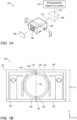
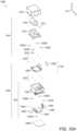
- FIG. 1Ashows an embodiment of a folded camera numbered 100.
- Folded camera 100comprises a lens actuator 102 carrying a lens 104, an OPFE (e.g. a prism, a mirror. etc.) 106 and an image sensor 108.
- Camera 100may be used to image a photographed object or a scene 110.
- light coming from the direction of object or scene 110 along a first direction (also referred to as "entrance optical axis”) 112enters OPFE 106, is folded to a second direction (also referred to as "lens optical axis ") 114, enters lens actuator 102 and then arrives at image sensor 108.
- Lens 104may comprise several lens elements, which may be held in one lens barrel or in a plurality of lens barrels. Lens 104 may have a fixed focal length or a changing (variable) focal length ("zoom lens"). Lens 104 may be shifted (actuated) for example for the purposes of focus (or auto focus - AF) or optical image stabilization (OIS). The actuation of lens 104 dictates that an air gap should be kept between the lens and other stationary parts such as an envelope 122 (see FIG. 1B ).
- Folded camera 100may include other parts such as an actuation mechanism for OPFE 106 (as in PCT/IB2017/052383), a housing (not shown for simplicity) for image sensor 108 to prevent stray light and mechanical damages, and other components known in the art, not shown for simplicity. More details on the operation of such a folded camera may be found in co-owned patent applications PCT/IB2015/056004 , PCT/IB2016/052179 and PCT/IB2017/058403 .
- FIG. 1Bshows a cross section of lens actuator 102 along a cut A-A to B-B seen in FIG. 1A .
- Lens actuator 102has an actuator height H A 102 between an external surface 140 of a top (upper) section (or “side") 126 of envelope 122 and an external surface 128 of a bottom (lower) section 130 of envelope 122.
- the top and bottom envelope sectionsmay be planar members with surfaces perpendicular to first direction 112 (i.e. with a plane normal aligned with first direction 112 ).
- top or “upper”refer to a side of the lens actuator (and of the folded camera) that is closer to and facing object or scene 110 along Y
- bottomrefers to a side of the lens actuator (and of the folded camera) that is farthest and facing away from the imaged object or scene along Y.
- Height H A 102is measured along the Y axis, or parallel to the first optical axis 112, as described below.
- optical heightrefers to a dimension of the respective object along the Y axis, namely along an axis perpendicular to lens optical axis 114 and parallel to entrance optical axis 112 facing the object.
- Actuator height H A 102is a sum of a lens height H L of lens 104, an upper height penalty 134 and a lower height penalty 136.
- Upper height penalty 134is defined as the distance between a topmost surface 138 of the lens and external top surface 140.
- Lower height penalty 136is defined as the distance between a lowest (bottom) surface 124 of the lens and external bottom surface 128.
- upper height penalty 134is the sum of the thickness of upper envelope section 126 and the size of an upper air gap 142 required between lens 104 and upper envelope section 126 (e.g. to allow actuation and movement of the lens for AF and/or OIS).
- Lower height penalty 136is the sum of the thickness of lower envelope section 130 and the size of a lower air gap 144 needed between lens 104 and lower envelope section 130 e.g. to allow actuation and movement of the lens for AF and/or OIS).
- height H A 102is the sum of the largest dimension of the lens in the Y direction (i.e. H L ) plus necessary air gaps 142 and 144 plus the thicknesses of the upper and lower envelope sections 126 and 130.
- lens actuator height H A 102is the largest dimension of actuator 120 along the Y direction.
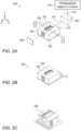
- FIG. 1Cshows another folded camera 150, similar to camera 100.
- Camera 150includes a lens actuator section with lens actuator 102 holding the lens, an image sensor holder section 152 that includes the image sensor and has a height Hs, and a prism holder section 154 that includes OPFE 106 and has a height H P .
- an infra-red (IR) filter 156may be positioned between lens 104 and image sensor 108, FIG. 1D.
- FIG. 1Dshows a side cut of camera 150 along a line B'-B' seen in FIG. 1C .
- a folded camera height H FCis limited by the maximum value of H P , H S and H A 102 .
- H FCmay be limited by lens actuator height H A 102 , and a reduction in H A 102 may lead to a reduction of H FC .
- the folded camera heightmay be determined by (and may be equal to) the lens actuator height.
- FIG. 2Ashows schematically the elements of a folded camera disclosed herein and numbered 200 in an exemplary coordinate system XYZ.
- Folded camera 200includes a reduced height lens actuator 202 having a top opening 203, a lens 204, an OPFE 206 and an image sensor 208, see also FIGS. 2-9 .
- OPFE 206folds light arriving from an object or scene 210 along a first direction (entrance optical axis) 212 parallel to the Y direction, to a second direction (lens optical axis) 214 parallel to the Z direction toward image sensor 208.
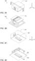
- FIGS. 2B-2Eprovide various views of lens actuator 202.
- FIG. 2Bshows lens actuator 202 in a top perspective view
- FIG. 2Cshows lens actuator 202 without an upper envelope section 216 from a top perspective view
- FIG. 2Dshows lens actuator 202 with a separated upper envelope section 216 from a bottom perspective view.
- Arrow 260shows the direction from which upper envelope section 216 is installed.
- FIG. 2Eshows lens actuator 202 in a section view between sections C-C and D-D in FIG. 2A .
- Top opening 203allows for an upper height penalty 234 smaller than upper height penalty 134 in lens actuator 102.
- Upper height penalty (air-gap) 234is measured between lens top surface 238 and an external top surface 224 of the upper envelope section 216.
- Upper height penalty (air-gap) 234is equal to the size of the air-gap between lens top surface 238 and an external top surface 224 measured along the first direction (Y axis).
- a second air gap 232is positioned on the diametrically opposed side of lens 204 relative to air gap 234. Air gap 232 is between lens 204 and an internal surface 236 of bottom envelope section 220, and allows the motion of lens 204 relative to bottom envelope section 220.
- H A 202is equal to the lens height H L plus the size of two air-gaps 234 and 232 plus the thickness of a bottom envelope section 220.
- the size of air-gap 234 and/or 232can be 50-150 ⁇ m
- the thickness of bottom envelope section 220is 100-150 ⁇ m
- lens actuator height H A 202can be equal to H L plus 250 ⁇ m-500 ⁇ m. All other dimensions being equal, a lens actuator height H A 202 in folded camera 200 will be smaller than lens actuator height H A 102 in folded camera 100.
- FIG. 2Fshows another embodiment of a folded camera disclosed herein and numbered 250, similar to folded camera 200.
- Camera 250includes lens actuator 202 with lens actuator height H A 202 and carrying lens 204.
- Image sensor 208is held in an image sensor holder 252.
- An OPFE 206is held in a prism holder 254.
- an IR filter 256is optionally positioned between lens 204 and image sensor 208.
- FIG. 2Gshows a side cut of camera 250 along a line D'-D' seen in FIG. 2F .
- folded camera height H FCis limited by the maximum of H A 202 , H P and H S .
- a reduction H A 202may lead to a reduction of H FC .
- a higher lensi.e. a lens with large H L
- the design of camera 250has an advantage over the design of camera 150 by either having a lower camera height for the same optics, or by having better optics for the same camera height.
- FIGS. 3A-3Eprovide various views of a second embodiment of a lens actuator numbered 302, in which the lens actuator envelope 314 has a bottom opening 304 in a bottom lid 306.
- Lens actuator 302is similar to lens actuator 202 and can be installed in a folded camera such as folded camera 200 in a similar manner.
- FIG. 3Ashows lens actuator 302 actuating lens 310 in a top perspective view
- FIG. 3Bshows lens actuator 302 without an upper envelope section from a top perspective view
- FIG. 3Cshows lens actuator 302 from a bottom perspective view.
- FIG. 3Dshows lens actuator 302 without an upper envelope section from a bottom perspective view
- FIG. 3Eshows lens actuator 302 in a section view between sections E-E and F-F in FIG. 3A .
- Bottom opening 304allows for a lower height penalty (air-gap) 336 and equal to the air-gap between a bottom surface 324 of the lens and an external bottom surface 328 of a bottom envelope section 306 measured along the first direction (Y axis). That is, lower height penalty 336 is smaller than lower height penalty 136 in FIGS. 1 .
- a second air gap 332is positioned on the diametrically opposed side of lens 310 relative to air gap 336.
- An air gap 232is between lens 310 and the internal surface 362 of upper envelope section 360, and allows the motion of lens 310 relative to upper envelope section 360.
- H A 302is equal to H L plus the size of the two air-gaps 332 and 336, plus the thickness of upper envelope section 360.
- the height of each of air-gaps 332 and 336can be 50-150 ⁇ m
- the thickness of upper envelope section 360can be 100-150 ⁇ m
- H A 302can be equal to the lens height H L plus 250 ⁇ m-500 ⁇ m. All other dimensions being equal, a lens actuator height H A 302 of camera 300 will be smaller than lens actuator height H A 102 in camera 100.
- lens actuator 302may be combined in a folded camera between an OPFE and an image sensor, such that the height of the folded camera H FC may be equal to the height of the lens actuator H A 302.
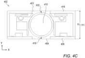
- FIGS. 4A-4Cprovide various views of a third embodiment of a folded lens actuator numbered 402 actuating a lens 410, in which a lens actuator envelope 414 has both a bottom opening and a top opening.
- FIG. 4Ashows lens actuator 402 in a top perspective view
- FIG. 4Bshows lens actuator 402 with a separated upper envelope section 416 from a bottom perspective view
- FIG. 4Cshows lens actuator 402 in a section view between sections G-G and H-H in FIG. 4A .
- Arrow 460shows the direction from which upper envelope section 216 is installed.
- Lens actuator 402includes upper envelope section 416 with an opening 403 like opening 203 in lens actuator 202 and a bottom envelope section 406 with an opening 404 like opening 304 in lens actuator 302.
- lens actuator 402combines the advantages provided by top opening 203 of lens actuator 202 and bottom opening 304 of lens actuator 302, with a final lens actuator height H A 402 smaller than the lens actuator heights in actuators 102, 202 and 302.
- lens actuator height H A 402is equal to the lens height plus the size of two air-gaps 418 and 432.
- the size of each of the air-gaps 418 and 432can be 50-150 ⁇ m and lens actuator height H A 402 can be equal to H L plus 100 ⁇ m or 250 ⁇ m or 300 ⁇ m.
- lens actuator 402may be combined in a folded camera between an OPFE and an image sensor, such that the height of the folded camera H FC may be equal to the height of the lens actuator H A , 402.
- FIGS. 5A , 5B , 6, 7 , 8 and 9show one exemplary lens actuator design using VCM actuation. Such a design may be used in conjunction with envelope designs of lens actuators 202, 302 and 402.
- FIG. 5A and FIG. 5Bshow, respectively, exploded bottom and top perspective views of a VCM 502.
- VCM 502comprises an envelope 506, an OIS/AF plate sub-assembly 508, four upper balls 510, a lens carrier sub-assembly 512, lens 514, four lower balls 516, an electronic sub-assembly 530, a base sub-assembly 540 and a lower plate 522.
- VCM 502is capable of actuating any of the lenses above in two orthogonal directions, for example for focusing and optical image stabilization.
- FIG. 6shows an exploded view of electronic sub-assembly 530.
- Electronic sub-assembly 530comprises an OIS Hall bar sensor 602, an OIS coil 604, an AF Hall bar sensor 606, a first rigid printed board circuit (PCB) 608, a second rigid PCB 610 and a flex PCB 612.
- the control of the motion of any of the lenses above or belowcan be done in close loop mode using the position sensing allowed by Hall bar sensors 602 and 606.
- FIG. 7shows an exploded view of base sub-assembly 540.
- Base sub-assembly 540comprises an AF VCM 704, an AF stepping yoke 702 and a base 706.
- FIG. 8shows an exploded view of lens carrier sub-assembly 512.
- Lens carrier sub-assembly 512comprises an OIS VCM magnet 804, an OIS sensing magnet 802 and a lens carrier 806.
- FIG. 9shows an exploded view of OIS/AF plate sub-assembly 508.
- OIS/AF plate sub-assembly 408comprises an AF motor magnet 902, an OIS stepping yoke 904 and an OIS/AF plate 906.
- FIGS. 10-14show another exemplary lens actuator design using VCM actuation.
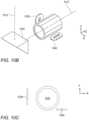
- FIG. 10Ashows an exploded view of a lens actuator 1004 using VCM actuation according to some aspects of presently disclosed subject matter
- lens actuator 1004comprises an envelope 1014 serving as protection for the lens and other mechanical parts, a lens 1016 with a lens optical axis 1012, a lens carrier (holder) 1018, a plurality (e.g. four) of stepping magnets 1020a, b, c and d, an OIS magnet 1022, four upper balls 1024, an AF magnet 1026, a middle chassis 1028, four lower balls 1030, a base 1032, a plurality (e.g.
- stepping yokes 1034a, b, c and dfour) of upper stepping yokes 1034a, b, c and d, an AF Hall sensor bar 1036, an AF coil 1038, an OIS coil 1040, a PCB 1042 serving as platform for placement of electrical components and electrical linkage between these electrical components, and OIS Hall sensor bar 1044 and a lower plate 1048 serving as bottom mechanical protection for the camera.
- some of the stepping yokesmay positioned on a first surface, and other stepping yokes may be positioned on a second surface, wherein the first and second surfaces are parallel.
- FIGS. 10B and 10Cshow the positioning of AF coil 1038 and OIS coil 1040 relative to the lens optical axis 1012 from two different views.
- Each coilhas a stadium shape, such that it has two long dimensions (typically 1-5mm long) and one short dimension (typically 0.1-0.5mm thick).
- Each coiltypically has a few tens of windings (for example, in a non-limiting range of 50-250), with an exemplary resistance of 10-30 ohm.
- the plane in which the long dimensions of the coil residewill be considered henceforth to be the respective "coil plane".
- an "OIS coil plane" of OIS coil 1040is parallel to the XZ plane, namely its two long dimensions are in XZ plane while its short dimension is along the Y axis.
- an "AF coil plane” of AF coil 1038is parallel to the YZ plane, namely its two long dimensions are in the YZ plane while its short dimension is along the X axis.
- the OIS coil planeis perpendicular to the AF coil plane.
- OIS coil 1040faces OIS magnet 1022 ( FIG. 10A ).
- the OIS magnetis a fixed (i.e. permenant) magnet.
- Magnet 1022may be fabricated (e.g.
- OIS magnet 1022has a magnetic field facing the negative Y direction, while on its negative X side, OIS magnet 1022 has a magnetic field facing the positive Y direction.
- a Lorenz forceis created by the magnetic filed of OIS magnet 1022 on OIS coil 1040 in the negative or positive Y direction. Consequently, an equal force is applied on OIS magnet 1022 in the Y direction.
- OIS coil 1040 in XZ planehas the advantage in that, while in actuation, OIS magnet is kept at a constant distance from OIS coil 1022. That is, Lorentz force for OIS is uniform for different AF positions, and the OIS position reading is linear for OIS motion and uniform for different AF positions.
- lens optical axis 1012is in the Z direction.
- Each of the OIS and AF planesis parallel to lens optical axis 1012.
- the OIS coil and the AF coilare on opposite sides of this plane. This feature has an advantage in that it reduces magnetic interference of the two VCMs.
- AF coil 1038faces AF magnet 1026.
- the AF magnetis a fixed (i.e. permenant) magnet.
- AF magnet 1026may be fabricated (e.g. sintered, cut) such that it has a changing magnetic field polarity: on its positive Z size, AF magnet 1026 has a magnetic field facing the negative X direction, while on its negative Z side OIS magnet 1022 has a magnetic field facing the positive X direction.
- a Lorenz forceis created by the magnetic filed of AF magnet 1026 on AF coil 1038 in the negative or positive Z direction. Consequently, an equal force is applied on AF magnet 1026 in the Z direction.
- AF coil 1038 in YZ planehas the advantage in that, while in actuation, the AF magnet is kept at a constant distance from OIS coil 1040. That is, the Lorentz force for AF is uniform for different OIS positions, and the AF position reading is linear for AF motion and uniform for different OIS positions.
- FIG. 10Dshows an envelope 1014' which is similar to envelope 1014 in VCM 1004, with an added top opening 1062.
- FIG. 10Eshows a lower plate 1048' similar to lower plate 1048 in VCM 1004, with an added bottom opening 1064. Openings 1062 and 1064 allow reducing the height of VCM 1004, in a manner similar to openings 203 and 304 described above. All descriptions of embodiments 202, 302, 402, with regard to benefits of top and bottom openings are applicable to the description of VCM 1004 and may be used in VCM 1004.
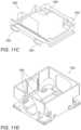
- FIGS. 11A and 11Bshow exploded views from two perspectives of a first VCM actuator numbered 1100 included in lens actuator 1004.
- VCM actuator 1100may be used for AF.
- VCM actuator 1100may be used for OIS.
- a top actuating sub-assembly 1110is movable relative to an AF stationary sub-assembly 1120 in a direction parallel to oprtical axis 1012.
- Top actuating sub-assembly 1110comprises lens 1016, lens holder 1018, middle chasis 1028, AF magnet 1026 and the four stepping magnets 1020a, b, c and d, OIS magnet 1022, and four upper balls 1024.
- Middle chassis 1028 and AF magnet 1026form a middle actuating sub-assembly 1130.
- AF stationary sub-assembly 1120comprises a lower stepping yoke 1050, OIS Hall sensor bar 1044, printed circuit board 1042, OIS coil 1040, AF coil 1038, AF Hall sensor bar 1036, four upper stepping yokes 1034a, b, c and d and base 1032 (only some of which are seen in these figures).
- Middle actuating sub-assembly 1130is movable relative to an AF stationary sub-assembly 1120 in a direction parallel to optical axis 1012 and movable relative to lens actuating sub-assembly 1210 in a direction perpendicular to optical axis 1012.
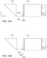
- FIGS. 11C and 11Dshow respectively four rails 1052 in middle chassis 1028 and four rails 1054 in base 1032. While one of rails 1054 is hidden in FIG. 11D , it is understood by a person skilled in the art that its location is symmetric with other visible rails.
- each of the four rails 1052faces one respective rail of rails 1054, while one ball of lower balls 1030 is between the rails.
- the rails and ball structureconfines the motion of top actuating sub-assembly 1110 relative to AF stationary sub-assembly 1120 in a direction parallel to optical axis 1012.
- top actuating sub-assembly 1110is pulled to AF stationary sub-assembly 1120 in the Y direction due to the magnetic force of magnets 1020 and upper stepping yokes 1034 (see below), while balls 1030 keep the distance between top actuating sub-assembly 1110 and AF stationary sub-assembly 1120 constant in the Y direction.
- the term "constant distance” with respect to moving partsrefers to a distance between the parts in a direction perpendicular to the motion direction that is constant with a tolerance of ⁇ 10 ⁇ m, ⁇ 30 ⁇ m, ⁇ 50 ⁇ m, or even ⁇ 100 ⁇ m.
- FIGS. 12A and 12Bshow exploded top and bottom perspective views of a second VCM actuator in lens sub-assembly 1004, numbered 1200.
- VCM actuator 1200includes a lens actuating sub-assembly 1210 movable relative to an OIS stationary sub-assembly 1220.
- VCM actuator 1200may be used for OIS.
- Lens actuating sub-assembly 1210comprises lens 1016, lens holder 1018, four stepping magnets 1020 and OIS magnet 1022 (which is also part of top actuating sub-assembly 1110 ).
- OIS stationary sub-assembly 1220comprises lens holder 1018, middle chasis 1028, AF magnet 1026, AF stationary sub-assembly 1120 and the four lower balls 1030.
- FIGS. 12C and 12Dshow respectively four rails 1056 in lens carrier 1018 and four rails 1058 in middle chassis 1028.
- VCM actuator 1200each of the four rails 1056 faces one respective rail of rails 1058, while one ball of upper balls 1024 is between the rails.
- the rails and ball structureconfine the motion of lens actuating sub-assembly 1210 relative to OIS stationary actuating sub-assembly 1220 in a direction perpendicular to optical axis 1012.
- lens actuating sub-assembly 1210is pulled to OIS stationary sub-assembly 1220 in the Y direction due to the magnetic force of magnets 1020 a,b,c and d and stepping yokes 1034a,b,c and d (see beolw), while upper balls 1024 keep the distance between lens actuating sub-assembly 1210 and OIS stationary sub-assembly 1220 constant in the Y direction.
- the lens actuating sub-assemblyis pulled toward the stationary sub-assembly, with the middle actuating sub-assembley positioned therebetween.
- an electrical current in AF coil 1038creates force on AF magnet 1026, driving middle chassis 1028 in directions parallel to lens optical axis 1012, for example along the positive or negative Z direction.
- Middle chassis 1028holds lens actuating sub-assembly 1210 and while moving in the AF direction it carries lens actuating sub-assembly 1210 along, such that lens 1016 is operative to focus on image sensor 1006, as required by optical demands.
- the AF movementis directed by the rolling and/or sliding of the four lower balls 1030 inside the four respective rails 1052 located in middle chassis 1028 and inside four compatible rails 1054 located in base 1032.
- actuator 1200 for OISIn use of actuator 1200 for OIS, electrical current in OIS coil 1040 creates force on OIS magnet 1022, driving lens carrier 1018 in directions perpendicular to the lens optical axis 1012 and parallel to the X axis (shown in the examplary coordinate system XYZ). During this movement, lens carrier 1018 (which holds lens 1016 ) moves together with the lens in any OIS direction.
- the movement for OISis directed by the rolling and/or sliding of four upper balls 1024 inside four rails 1056 located on lens carrier 1018 and inside another four compatible rails 1058 located on the middle chassis 1028.
- the four stepping magnets 1020a, 1020b, 1020c and 1020d located on the lens carrier 1018are assocated with four stepping yokes 1034a, 1034b, 1034c and 1034d located on AF stationary sub-assembly 1120, creating a stepping force indicated by arrows in a direction perpendicular to optical axis 1012.
- Stepping magnets 1020a-d and stepping yokes 1034a-dare seen in FIG. 13A , which shows an exploded view of VCM 1100, and in FIG. 13B which shows only the magnets and yokes along with the force direction, which is directed in the negative Y direction.
- lens actuating sub-assembly 1210is pulled toward AF stationary sub-assembly 1120, while OIS stationary sub-assembly 1220 is positioned therebetween.
- Upper balls 1024 located between lens actuating sub-assembly 1210 and OIS stationary sub-assembly 1220prevent contact between the two sub-assemblies.
- lower balls 1030 located between OIS stationary sub-assembly 1220 and AF stationary sub-assembly 1120prevent contact between the two sub-assemblies.
- the pull force created between four stepping magnets 1020 and four stepping yokes 1034hold actuator 1100 as one unit and prevent all moving parts from coming apart.
- the three stepping magnetsare used only for stepping, while the fourth magnet is used for stepping and sensing.
- FIGS. 14A and 14Bshow top actuating sub-assembly 1110 in, respectively, an exploded perspective view and an assembled view.
- lens carrier 1018has an an opening 1402 which allows light to pass from an OPFE to lens 1016. Opening 1402 is surrounded by walls 1404 a, b, c and d.
- middle chassis 1028comprises walls 1406 a, b, c and d.
- Wall 1406bcan be used to add mechanical strength and connect between the rails.
- FIGS. 14C and 14Dshow two different embodiments in cross section along the optical axis of top actuating sub-assembly 1110 and a prism 1410. The embodiments shown in FIGS. 14C and 14D describe two relative positions of walls 1406b and 1404b. In the embodiment of FIG. 14C , wall 1406b is located below wall 1404b (in the -Y direction).
- a distance 1408denotes the minimal distance of top actuating sub-assembly 1110 from prism 1410.
- Distance 1408is determined by a stroke for AF of top actuating sub-assembly 1110, as required by optical needs and assembly togruces, as required by mechanical needs.
- Distance 1408is constant in both configurations ( FIGS. 14C and 14D ).
- the configuration in FIG. 14Chas an advantage, since it allows a shorter actuator along the optical axis direction (-Z direction), namely a reduction in the length of folded camera 1000 ( FIG. 10A ).
- FIG. 15shows a dual camera 1500 comprising an upright camera 1502 and a folded camera 1504.
- Folded camera 1504may include a lens actuator like any actuator/VCM disclosed above, for example actuators/VCMs 102, 202, 302, 402, 502 or 1004.
Landscapes
- Physics & Mathematics (AREA)
- General Physics & Mathematics (AREA)
- Optics & Photonics (AREA)
- Engineering & Computer Science (AREA)
- Multimedia (AREA)
- Signal Processing (AREA)
- Human Computer Interaction (AREA)
- Studio Devices (AREA)
- Lens Barrels (AREA)
- Adjustment Of Camera Lenses (AREA)
Abstract
Description
- This application claims priority to
U.S. provisional patent applications Nos. 62/626,306 filed February 5, 2018 62/658,819 filed April 17, 2018 62/672,754 filed May 17, 2018 62/677,012 filed May 27, 2018 - Embodiments disclosed herein relate in general to digital cameras and in particular to thin folded optics cameras.
- In recent years, mobile devices such as cell-phones (and in particular smart-phones), tablets and laptops have become ubiquitous. Many of these devices include one or two compact cameras including, for example, a main rear-facing camera (i.e. a camera on the back side of the device, facing away from the user and often used for casual photography) and a secondary front-facing camera (i.e. a camera located on the front side of the device and often used for video conferencing).
- Although relatively compact in nature, the design of most of these cameras is similar to the traditional structure of a digital still camera, i.e. it comprises a lens assembly (or a train of several optical elements) placed on top of an image sensor. The lens assembly (also referred to as "lens module" or simply "lens") refracts the incoming light rays and bends them to create an image of a scene on the sensor. The dimensions of these cameras are largely determined by the size of the sensor and by the height of the optics. These are usually tied together through the focal length ("f") of the lens and its field of view (FOV) - a lens that has to image a certain FOV on a sensor of a certain size has a specific focal length. Keeping the FOV constant, the larger the sensor dimensions the larger the focal length and the optics height.
- The assembly process of a traditional camera may include handling of a few sub-assemblies: a lens, a sensor board sub-assembly and an actuator. The lens may include a lens barrel made for example of plastic or metal and includes a few (3-7) lens elements which may be made of plastic or glass. The sensor board sub-assembly may include the image sensor, a printed circuit board (PCB) and electronics needed for the operation of the camera, as known in the art. The actuator is used to move the lens for optical needs (for example for focusing (and in particular auto focusing (AF)) and/or optical image stabilization (OIS)) and for mechanical protection of the other parts of the camera. In known art, the lens is inserted and attached (e.g. glued) to the actuator from one side, along the lens optical axis, whereas the sensor board is attached (e.g. glued) to the actuator from the opposite side along the optical axis.
- "Folded camera modules" (or simply "folded cameras") are known and have been suggested for incorporation in various "host" devices (e.g. smart-phones, tablets, laptops, smart TVs, etc.). In a folded camera, an optical path folding element (OPFE) e.g. a prism or a mirror (otherwise referred to herein collectively as "reflecting element") tilts light arriving in a first optical path or direction (e.g. perpendicular to a back surface of a smart-phone) to a second optical path or direction (e.g. parallel to the smart-phone back surface). If the folded camera is part of a dual-aperture camera, this provides a folded optical path through one lens assembly (e.g. a Tele lens). Such a camera is referred to herein as "folded-lens dual-aperture camera" or "dual-aperture camera with a folded lens". In general, the folded camera may be included in a multi-aperture camera, for example together with two "non-folded" (upright) camera modules in a triple-aperture camera, or in multi-aperture cameras with more than 3 cameras.
- Actuators used for AF and OIS in smart-phone cameras are known. A commonly used actuator is based on voice coil motor (VCM) technology. In VCM technology, a permanent (or "fixed") magnet and a coil are used to create actuation force. The coil is positioned in the vicinity of the magnetic field of the fixed magnet. Upon driving current in the coil, a Lorentz force is created on the coil, an in return an equal counter-force is applied on the magnet. The magnet or the coil is rigidly attached to an optical element to construct an actuating assembly. The actuating assembly is then moved by the magnetic Lorenz force. A VCM may also be referred to as "VCM engine" and an actuator including such a VCM (or VCM engine) may be referred to as to as "VCM actuator" or simply "actuator". An actuator may be partially or fully surrounded by an envelope (sometimes also referred to as "shield") having an envelope thickness.
- In a folded camera with a moving lens mechanism (actuated by an actuator/VCM), at least one air gap is needed to allow movement. The envelope and other optional top and bottom elements or parts (e.g. a plate) added to protect the mechanism increase the total height of the actuator. A small height of a folded camera is important to allow a host device that includes it to be as thin as possible. The height of the camera is limited many times by the industrial design. In contrast, increasing the available height for the lens, sensor and OPFE may improve optical properties.
- Envelope and other optional top and/or bottom parts add to the folded camera height. The height thus has a "penalty" that needs to be reduced.
- In VCMs, in addition to the magnetic force, a mechanical rail is known to set the course of motion for the optical element. The mechanical rail keeps the motion of the lens in a desired path, as required by optical needs. One example of mechanical rail is known in the art as "spring-guided rail", in which a spring or set of springs is used to set the motion direction. A VCM that includes a spring-guided rail is referred to as a "spring-guided VCM". For example,
US patent application No. 20110235196 discloses a lens element shifted in a linear spring rail to create focus. For example, international patent applicationPCT/IB2016/052179 PCT/IB2016/052179 - Another example mechanical rail is known in the art a "ball-guided rail", see e.g.
US patent No. 8810714 . With a ball-guided rail, the lens is bound to move in the desired direction by set of balls confined in a groove (also referred to as "slit"). A VCM that includes a ball-guided rail is referred to as a "ball-guided VCM". A ball-guided VCM has several advantages over a spring-guided VCM. These include: (1) lower power consumption, because in a spring-guided VCM the magnetic force has to oppose a spring mechanical force, which does not exist in a ball-guided VCM, and (2) higher reliability in drops that may occur during the life cycle of a camera that includes the VCM. The actuation method inUS patent 8810714 is designed for an exemplary non-folded lens, where the lens optical axis is directly pointed at the object to be photographed and cannot be used in a folded camera. US20180017844 discloses a lens driving module including a reflecting element, a base, a frame, a holder, an optical lens, a first electromagnetic driving assembly, and a second electromagnetic driving assembly. The frame is connected to the base, and the holder holds the optical lens and movably connects to the base. The reflecting element reflects light from the outside along a light incident direction to an optical lens along a first direction, wherein the light incident direction is substantially perpendicular to the first direction. The first and second electromagnetic driving assemblies are configured to force the holder and the optical lens to move relative to the base, wherein the first and second electromagnetic driving assemblies are situated in different positions in the light incident direction.US20110121666A1 discloses a VCM, the VCM including a bobbin formed with a coil at an outer surface thereof; at least one permanent magnet facing the coil formed at the bobbin; a cylindrical yoke encompassing the bobbin and the permanent magnet and including a metal member for blocking a magnetic field generated by the coil; a base coupled to the yoke; and an elastic member including a first elastic member interposed between the yoke and the permanent magnet for elastically supporting the bobbin and a second elastic member interposed between the base and the permanent magnet.US10126633B2 - There is a need for, and it would be advantageous to reduce height and length penalties in folded cameras both with respect to structures and to the design of a linear ball guided VCM.
- Embodiments disclosed herein relate to reduced height lens actuators (e.g. of VCM design) and folded cameras having such actuators. The term "lens" may refer to a lens assembly, comprising a train of several optical elements and a lens housing the lens elements. A lens is characterized by a fixed effective focal length (EFL), a clear aperture (CA), both of which are defined in international patent application
PCT/IB2018/050988 - The height of actuators and folded cameras is determined mainly by the lens diameter (height) and a "penalty". In this description, any height that is additional to the lens diameter is considered herein to be a "penalty". More specifically, a penalty is the sum of an upper (or top) height penalty and a lower (or bottom) height penalty, with the "upper", "lower" and "penalty" terms described in detail below.
- In various embodiments, a reduced height lens actuator disclosed herein may have an envelope with a bottom opening, a top opening or both bottom and top openings. A folded camera including such as actuator has a "reduced height penalty", the reduction in height penalty brought about by the bottom opening, top opening or both bottom and top openings which allow to reduce the distance between the lens and outmost (e.g. top or bottom) surfaces of the envelope. The envelope may surround the lens actuator (e.g. be made of a sheet folded or bent around the lens actuator, or made of a few parts soldered or glued together. As mentioned, the envelope has an envelope thickness. The term "envelope thickness" refers to the thickness of the material forming the envelope (e.g. stainless steel, plastic, copper, etc.). If the envelope is made of different parts, the term "envelope thickness" refers to the thickness of each part.
- In this description, an optical path-folding element (OPFE) is an optical element comprising a reflective plane, the OPFE capable of folding the light from one axis to a second axis, the two optical axes being substantially perpendicular to one another, with the reflective plane being tilted by 45 degrees relative to both optical axes.
- In various embodiments, there are provided folded cameras, comprising: a movable lens positioned in an optical path between an OPFE and an image sensor, wherein the OPFE folds light from a first direction to a second direction and wherein the lens includes a lens optical axis parallel to the second direction, a lens height substantially aligned with the first direction, a first lens surface and a second lens surface diametrically opposed to the first surface, the first and second lens surfaces being in planes perpendicular to the first direction; and an envelope surrounding the lens in at least some sections and including, along the first direction, a first envelope section with a first opening positioned on a first side of the lens and a second envelope section without an opening positioned on a second, diametrically opposed side of the lens, wherein the first lens surface is distanced along the first direction from an external surface of the first envelope section by a first air gap, wherein the second lens surface is distanced along the first direction from an internal surface of the second envelope section by a second air gap, wherein the second envelope section has a second envelope section thickness and wherein the folded camera has a camera height substantially aligned with the first direction and substantially equal to a sum of the lens height, the first air gap, the second air gap and the second envelope section thickness.
- In various embodiments, there are provided folded cameras, comprising: a movable lens positioned in an optical path between an optical path folding element (OPFE) and an image sensor, wherein the OPFE folds light from a first direction to a second direction and wherein the lens includes a lens optical axis parallel to the second direction, a lens height substantially aligned with the first direction, a first lens surface and a second lens surface diametrically opposed to the first surface, the first and second lens surfaces being in planes perpendicular to the first direction; and an envelope surrounding the lens and including, along the first direction, a first envelope section with a first opening positioned on a first side of the lens and a second envelope section with a second opening positioned on a second, diametrically opposed side of the lens, wherein the first lens surface is distanced along the first direction from an external surface of the first envelope section by a first air gap, wherein the second lens surface is distanced along the first direction from an external surface of the second envelope section by a second air gap, and wherein the folded camera has a camera height substantially aligned with the first direction and substantially equal to a sum of the lens height, the first air gap and the second air gap.
- In some exemplary embodiments of a folded camera as above or below, each of the first and second air gaps may be in the range of 10-50µm. In some exemplary embodiments, each of the first and second air gaps may be in the range of 10-100µm. In some exemplary embodiments, each of the first and second air gaps may be in the range of 10-150µm.
- In some exemplary embodiments, the lens may be movable for focusing.
- In some exemplary embodiments, the lens may be movable for optical image stabilization.
- In some exemplary embodiments, the lens may be movable in two directions in a single plane for focusing and optical image stabilization, the single plane being perpendicular to the first direction.
- In some exemplary embodiments, a folded camera as above has a height that does not exceed the lens height by more than about 600 µm. In some embodiments, the folded camera height does not exceed the lens height by more than 400 µm. In some embodiments, the folded camera height does not exceed the lens height by more than 300 µm.
- In some exemplary embodiments, a folded camera as above may be included together with an upright camera in a dual-camera.
- In an embodiment there is provided a folded camera, comprising: a lens actuator for moving a lens in at least one direction and including an envelope surrounding the lens in at least some sections and having an envelope thickness, the lens having a lens height and being positioned in an optical path between an optical path folding element and an image sensor and movable in the at least one direction, wherein the folded camera has a height smaller than the sum of the lens height, the size of a first air gap from the lens to the envelope, the size of a second air gap from the lens to the envelope and twice the envelope thickness.
- In an embodiment there is provided a folded camera,: a lens actuator for moving a lens in at least one direction and including an envelope surrounding the lens in at least some sections and having an envelope thickness, the lens having a lens height and being positioned in an optical path between an optical path folding element and an image sensor and movable in the at least one direction, wherein the folded camera has a height smaller than the sum of the lens height, the size of a first air gap from the lens to an external surface of the envelope, the size of a second air gap from the lens to the envelope and the envelope thickness.
- In various embodiments, there are provided lens actuators for moving a lens, the lens having a lens optical axis parallel to a second direction and a lens height substantially aligned with a first direction that is substantially perpendicular to the second direction, the actuators comprising: an envelope surrounding the lens in at least some sections and including, along the first direction, a first envelope section with a first opening positioned on a first side of the lens and a second envelope section and without an opening positioned on a second, diametrically opposed side of the lens, wherein the first lens surface is distanced along the first direction from an external surface of the first envelope section by a first air gap, wherein the second lens surface is distanced along the first direction from an internal surface of the second envelope section by a second air gap, wherein the second envelope section has a second envelope section thickness and wherein the folded camera has a camera height substantially aligned with the first direction and substantially equal to a sum of the lens height, the first air gap, the second air gap and the second envelope section thickness.
- In various embodiments, there are provided lens actuators for moving a lens, the lens having a lens optical axis parallel to a second direction and a lens height substantially aligned with a first direction that is substantially perpendicular to the second direction, the actuators comprising: an envelope surrounding the lens in at least some sections and including, along the first direction, a first envelope section with a first opening positioned on a first side of the lens and a second envelope section with a second opening positioned on a second, diametrically opposed side of the lens, wherein the first lens surface is distanced along the first direction from an external surface of the first envelope section by a first air gap, wherein the second lens surface is distanced along the first direction from an external surface of the second envelope section by a second air gap, and wherein the folded camera has a camera height substantially aligned with the first direction and substantially equal to a sum of the lens height, the first air gap and the second air gap.
- In some exemplary embodiments of an actuator as above or below, each of the first and second air gaps may be in the range of 10-50µm. In some exemplary embodiments, each of the first and second air gaps may be in the range of 10-100µm. In some exemplary embodiments, each of the first and second air gaps may be in the range of 10-150µm.
- In some exemplary embodiments, the lens may be movable for focusing.
- In some exemplary embodiments, the lens may be movable for optical image stabilization.
- In some exemplary embodiments, the lens may be movable in two directions in a single plane for focusing and optical image stabilization, the single plane being perpendicular to the first direction.
- In some exemplary embodiments, an actuator as above or below has a height that does not exceed the lens height by more than about 600 µm. In some embodiments, the actuator height does not exceed the lens height by more than 400 µm. In some embodiments, the actuator height does not exceed the lens height by more than 300 µm.
- In various embodiments, there are provided folded cameras comprising: a lens positioned in an optical path between an optical path folding element and an image sensor, the lens having a lens height and an optical axis, wherein the folded camera has a height not exceeding the lens height by more than 500 µm.
- In an exemplary embodiment, the folded camera above may have a height not exceeding the lens height by more than 400 µm.
- In an exemplary embodiment, the folded camera above may have a height not exceeding the lens height by more than 250µm.
- In an exemplary embodiment, the folded camera above may be included together with an upright camera in a dual-camera.
- In an embodiment there is provided an actuator for actuating a lens having a lens optical axis for AF and optical image stabilization OIS, the actuator comprising: a stationary sub-assembly that includes an OIS coil having an OIS coil plane and an AF coil having an AF coil plane; and a lens actuating sub-assembly movable relative to the stationary sub-assembly and including a lens holder holding the lens, wherein the OIS coil plane is perpendicular to AF coil plane and wherein the lens optical axis lies between the OIS coil plane and the AF coil plane.
- In an exemplary embodiment, the stationary sub-assembly further includes a plurality of upper stepping yokes, wherein the lens actuating sub-assembly further includes a plurality of stepping magnets coupled to the plurality of upper stepping yokes, and wherein the plurality of stepping yokes and the plurality of stepping magnets are operable to create stepping forces in a direction perpendicular to the lens optical axis for stepping.
- In some exemplary embodiments, an actuator as above or below further comprises a middle actuating sub-assembly for AF and OIS positioned between the stationary sub-assembly and the lens top actuating sub-assembly.
- In some exemplary embodiments, the stationary sub-assembly further includes an OIS Hall sensor bar used in conjunction with one of the stepping magnets to perform position sensing.
- In some exemplary embodiments, some yokes of the plurality of stepping yokes are positioned on a first surface, wherein other yokes of the plurality of stepping yokes are positioned on a second surface, and wherein the first and second surfaces are parallel.
- In some exemplary embodiments, an actuator as above may be included in a folded camera.
- In various embodiments, there are provided folded cameras comprising: a lens having a lens optical axis, an optical path folding elelement for folding light from a first direction to a second direction, the second direction being essentially aligned with the lens optical axis, an image sensor and an actuator for actuating the lens for AF and OIS, the actuator comprising an AF VCM that includes an AF coil positioned in an AF plane and is operable to move the lens in an AF direction, and an OIS VCM that includes an OIS coil positioned in an OIS plane and is operable to move the lens in an OIS direction, wherein the AF plane and the OIS plane are perpendicular to each other, and wherein the two VCMs are located on opposite sides of a plane defined by the first and second directions.
- Non-limiting examples of embodiments disclosed herein are described below with reference to figures attached hereto that are listed following this paragraph. Identical structures, elements or parts that appear in more than one figure are generally labeled with a same numeral in all the figures in which they appear. The drawings and descriptions are meant to illuminate and clarify embodiments disclosed herein and should not be considered limiting in any way. In the drawings:
FIG. 1A shows an embodiment of a folded camera disclosed herein;FIG. 1B shows a cross section along cuts A-A and B-B of the folded camera ofFIG. 1A ;FIG. 1C shows another folded camera disclosed herein;FIG. 1D shows a side cut along a line B'-B' of the folded camera inFIG. 1C ;FIG. 2A shows schematically the elements of a folded camera disclosed herein;FIG. 2B shows an embodiment of a reduced height folded lens actuator with a bottom opening disclosed herein in a top perspective view;FIG. 2C shows the actuator embodiment ofFIG. 2B without an upper envelope from a top perspective view;FIG. 2D shows the actuator embodiment ofFIG. 2B from a bottom perspective view;FIG. 2E shows the actuator embodiment ofFIG. 2B in a front section view along sections between sections C-C and D-D;FIG. 2F shows an embodiment of a reduced height folded camera that includes a lens actuator as inFIGS. 2B-2E ;FIG. 2G shows a side cut along a cut D'-D' of the folded camera embodiment ofFIG. 2F ;FIG. 3A shows an embodiment of a reduced height folded lens actuator with a top opening disclosed herein in a top perspective view;FIG. 3B shows the actuator embodiment ofFIG. 3A without an upper envelope from a top perspective view;FIG. 3C shows the actuator embodiment ofFIG. 3A from a bottom perspective view;FIG. 3D shows the actuator embodiment ofFIG. 3B from a bottom perspective view;FIG. 3E shows the actuator embodiment ofFIGS. 3A-3D in a front section view along sections between sections A-A and B-B inFIG. 3A ;FIG. 4A shows an embodiment of a reduced height folded lens actuator with a top opening and a bottom opening disclosed herein in a top perspective view;FIG. 4B shows the actuator embodiment ofFIG. 4A with a separated upper envelope from a bottom perspective view;FIG. 4C shows the actuator embodiment ofFIG. 4A with a top opening and a bottom opening from a bottom perspective view;FIG. 4C shows the actuator embodiment ofFIG. 4A in a section view between sections H-H and I-I inFIG. 4A ;FIG. 5A shows an exploded view of the reduced height folded lens actuator ofFIGS. 4A-C ;FIG. 5B shows another exploded view of the reduced height folded lens actuator ofFIGS. 4A-C ;FIG. 6 shows an exploded view of an electronic sub-assembly in a reduced height folded lens actuator disclosed herein;FIG. 7 shows an exploded view of a base sub-assembly in a reduced height folded lens actuator disclosed herein;FIG. 8 shows an exploded view of a lens sub-assembly in a reduced height folded lens actuator disclosed herein;FIG. 9 shows an exploded view of an OIS/AF plate sub-assembly in a reduced height lens actuator disclosed herein;FIG. 10A shows an exploded view of an embodiment and various parts of a folded camera lens sub-assembly according to some aspects of presently disclosed subject matter;FIG. 10B shows the positioning of the AF and OIS coils relative to the lens optical axis from one view;FIG. 10C shows the positioning of the AF and OIS coils relative to the lens optical axis from another view;FIG. 10D shows a envelope in the lens sub-assembly ofFIG. 10A with an added top opening;FIG. 10E shows a lower plate in the lens sub-assembly ofFIG. 10A with an added bottom opening;FIGS. 11A and11B show exploded views from two perspectives of a first VCM actuator in the lens sub-assembly;FIGS. 11C and 11D show respectively rails in the middle chassis and rails in the base;FIGS. 12A and 12B show exploded views from two perspectives of a second VCM actuator in the lens sub-assembly;FIGS. 12C and 12D show respectively rails in the middle chassis and rails in the base;FIGS. 13A and 13B show parts of the lens sub-assembly related to the actuation;FIGS. 14A and 14B show the top actuating sub-assembly in respectively, an exploded perspective view and an assembled view;FIGS. 14C and 14D show two different embodiments in cross section along the optical axis of the top actuating sub-assembly ofFIGS. 14A, 14B and a prism;FIG. 15 shows an embodiment of a dual camera comprising an upright camera and a folded camera with an actuator disclosed above or below.FIG. 1A shows an embodiment of a folded camera numbered100. Foldedcamera 100 comprises alens actuator 102 carrying alens 104, an OPFE (e.g. a prism, a mirror. etc.)106 and animage sensor 108.Camera 100 may be used to image a photographed object or ascene 110. In an example, light coming from the direction of object orscene 110 along a first direction (also referred to as "entrance optical axis")112 entersOPFE 106, is folded to a second direction (also referred to as "lens optical axis ")114, enterslens actuator 102 and then arrives atimage sensor 108.Lens 104 may comprise several lens elements, which may be held in one lens barrel or in a plurality of lens barrels.Lens 104 may have a fixed focal length or a changing (variable) focal length ("zoom lens").Lens 104 may be shifted (actuated) for example for the purposes of focus (or auto focus - AF) or optical image stabilization (OIS). The actuation oflens 104 dictates that an air gap should be kept between the lens and other stationary parts such as an envelope122 (seeFIG. 1B ). Foldedcamera 100 may include other parts such as an actuation mechanism for OPFE106 (as in PCT/IB2017/052383), a housing (not shown for simplicity) forimage sensor 108 to prevent stray light and mechanical damages, and other components known in the art, not shown for simplicity. More details on the operation of such a folded camera may be found in co-owned patent applicationsPCT/IB2015/056004 PCT/IB2016/052179 PCT/IB2017/058403 FIG. 1B shows a cross section oflens actuator 102 along a cut A-A to B-B seen inFIG. 1A .Lens actuator 102 has anactuator heightH A 102 between anexternal surface 140 of a top (upper) section (or "side")126 ofenvelope 122 and anexternal surface 128 of a bottom (lower)section 130 ofenvelope 122. The top and bottom envelope sections may be planar members with surfaces perpendicular to first direction112 (i.e. with a plane normal aligned with first direction112). As used herein, the terms "top" or "upper" refer to a side of the lens actuator (and of the folded camera) that is closer to and facing object orscene 110 along Y, while "bottom", "below" or "lower" refers to a side of the lens actuator (and of the folded camera) that is farthest and facing away from the imaged object or scene along Y. HeightHA 102 is measured along the Y axis, or parallel to the firstoptical axis 112, as described below. As used herein, "height", "part height", "module height", "actuator height" or "camera height", refer to a dimension of the respective object along the Y axis, namely along an axis perpendicular to lensoptical axis 114 and parallel to entranceoptical axis 112 facing the object.- Actuator heightHA 102 is a sum of a lens heightHL of
lens 104, anupper height penalty 134 and alower height penalty 136.Upper height penalty 134 is defined as the distance between atopmost surface 138 of the lens and externaltop surface 140.Lower height penalty 136 is defined as the distance between a lowest (bottom)surface 124 of the lens and externalbottom surface 128. In other words,upper height penalty 134 is the sum of the thickness ofupper envelope section 126 and the size of anupper air gap 142 required betweenlens 104 and upper envelope section126 (e.g. to allow actuation and movement of the lens for AF and/or OIS).Lower height penalty 136 is the sum of the thickness oflower envelope section 130 and the size of alower air gap 144 needed betweenlens 104 andlower envelope section 130 e.g. to allow actuation and movement of the lens for AF and/or OIS). In turn, heightHA 102 is the sum of the largest dimension of the lens in the Y direction (i.e.HL) plusnecessary air gaps lower envelope sections FIG. 1C shows another foldedcamera 150, similar tocamera 100.Camera 150 includes a lens actuator section withlens actuator 102 holding the lens, an imagesensor holder section 152 that includes the image sensor and has a heightHs, and aprism holder section 154 that includesOPFE 106 and has a heightHP. Additionally, an infra-red (IR)filter 156 may be positioned betweenlens 104 andimage sensor 108,FIG. 1D. FIG. 1D shows a side cut ofcamera 150 along a line B'-B' seen inFIG. 1C . Incamera 150, a folded camera heightHFC is limited by the maximum value ofHP,HS andHA 102. ThusHFC may be limited by lens actuator heightHA 102, and a reduction inHA 102 may lead to a reduction ofHFC. In other words, the folded camera height may be determined by (and may be equal to) the lens actuator height.FIG. 2A shows schematically the elements of a folded camera disclosed herein and numbered200 in an exemplary coordinate system XYZ. Foldedcamera 200 includes a reducedheight lens actuator 202 having atop opening 203, alens 204, anOPFE 206 and animage sensor 208, see alsoFIGS. 2-9 .OPFE 206 folds light arriving from an object orscene 210 along a first direction (entrance optical axis)212 parallel to the Y direction, to a second direction (lens optical axis)214 parallel to the Z direction towardimage sensor 208.FIGS. 2B-2E provide various views oflens actuator 202.FIG. 2B showslens actuator 202 in a top perspective view,FIG. 2C showslens actuator 202 without anupper envelope section 216 from a top perspective view.FIG. 2D showslens actuator 202 with a separatedupper envelope section 216 from a bottom perspective view.Arrow 260 shows the direction from whichupper envelope section 216 is installed.FIG. 2E showslens actuator 202 in a section view between sections C-C and D-D inFIG. 2A .Top opening 203 allows for anupper height penalty 234 smaller thanupper height penalty 134 inlens actuator 102. Upper height penalty (air-gap)234 is measured between lenstop surface 238 and an externaltop surface 224 of theupper envelope section 216. Upper height penalty (air-gap)234 is equal to the size of the air-gap between lenstop surface 238 and an externaltop surface 224 measured along the first direction (Y axis). Asecond air gap 232 is positioned on the diametrically opposed side oflens 204 relative toair gap 234.Air gap 232 is betweenlens 204 and an internal surface236 ofbottom envelope section 220, and allows the motion oflens 204 relative tobottom envelope section 220. In some examples,HA 202 is equal to the lens heightHL plus the size of two air-gaps bottom envelope section 220. Exemplarily, the size of air-gap 234 and/or232 can be 50-150µm, the thickness ofbottom envelope section 220 is 100-150µm, and lens actuator heightHA 202 can be equal toHL plus 250µm-500µm. All other dimensions being equal, a lens actuator heightHA 202 in foldedcamera 200 will be smaller than lens actuator heightHA 102 in foldedcamera 100.FIG. 2F shows another embodiment of a folded camera disclosed herein and numbered250, similar to foldedcamera 200.Camera 250 includeslens actuator 202 with lens actuator heightHA 202 and carryinglens 204.Image sensor 208 is held in animage sensor holder 252. AnOPFE 206 is held in aprism holder 254. Additionally, in some embodiments, anIR filter 256 is optionally positioned betweenlens 204 andimage sensor 208.FIG. 2G shows a side cut ofcamera 250 along a line D'-D' seen inFIG. 2F . Incamera 250, folded camera heightHFC is limited by the maximum ofHA 202,HP andHS. Thus, a reductionHA 202 may lead to a reduction ofHFC.- Alternatively, for a given folded camera height, a higher lens (i.e. a lens with largeHL) with better optical properties can be used in a design with an opening, relative to a design with no opening. Evidently, the design of
camera 250 has an advantage over the design ofcamera 150 by either having a lower camera height for the same optics, or by having better optics for the same camera height. FIGS. 3A-3E provide various views of a second embodiment of a lens actuator numbered302, in which thelens actuator envelope 314 has abottom opening 304 in abottom lid 306.Lens actuator 302 is similar tolens actuator 202 and can be installed in a folded camera such as foldedcamera 200 in a similar manner.FIG. 3A showslens actuator 302actuating lens 310 in a top perspective view,FIG. 3B showslens actuator 302 without an upper envelope section from a top perspective view.FIG. 3C showslens actuator 302 from a bottom perspective view.FIG. 3D showslens actuator 302 without an upper envelope section from a bottom perspective view, andFIG. 3E showslens actuator 302 in a section view between sections E-E and F-F inFIG. 3A .Bottom opening 304 allows for a lower height penalty (air-gap)336 and equal to the air-gap between abottom surface 324 of the lens and anexternal bottom surface 328 of abottom envelope section 306 measured along the first direction (Y axis). That is,lower height penalty 336 is smaller thanlower height penalty 136 inFIGS. 1 . Asecond air gap 332 is positioned on the diametrically opposed side oflens 310 relative toair gap 336. Anair gap 232 is betweenlens 310 and theinternal surface 362 ofupper envelope section 360, and allows the motion oflens 310 relative toupper envelope section 360. In some examples,HA 302 is equal toHL plus the size of the two air-gaps upper envelope section 360. Exemplarily, the height of each of air-gaps upper envelope section 360 can be 100-150µm, andHA 302 can be equal to the lens heightHL plus 250µm-500µm. All other dimensions being equal, a lens actuator heightHA 302 of camera300 will be smaller than lens actuator heightHA 102 incamera 100. Likelens actuator 202,lens actuator 302 may be combined in a folded camera between an OPFE and an image sensor, such that the height of the folded camera HFC may be equal to the height of thelens actuator H A302.FIGS. 4A-4C provide various views of a third embodiment of a folded lens actuator numbered402 actuating alens 410, in which alens actuator envelope 414 has both a bottom opening and a top opening.FIG. 4A showslens actuator 402 in a top perspective view,FIG. 4B showslens actuator 402 with a separatedupper envelope section 416 from a bottom perspective view, andFIG. 4C showslens actuator 402 in a section view between sections G-G and H-H inFIG. 4A .Arrow 460 shows the direction from whichupper envelope section 216 is installed.Lens actuator 402 includesupper envelope section 416 with anopening 403 like opening203 inlens actuator 202 and abottom envelope section 406 with anopening 404 like opening304 inlens actuator 302. The twoopenings lens 410. Thus,lens actuator 402 combines the advantages provided bytop opening 203 oflens actuator 202 andbottom opening 304 oflens actuator 302, with a final lensactuator heightH A 402 smaller than the lens actuator heights inactuators actuator heightH A 402 is equal to the lens height plus the size of two air-gaps gaps actuator heightH A 402 can be equal toHL plus 100µm or 250µm or 300µm. Likelens actuator 202,lens actuator 402 may be combined in a folded camera between an OPFE and an image sensor, such that the height of the folded cameraHFC may be equal to the height of the lens actuator HA,402.FIGS. 5A ,5B ,6, 7 ,8 and 9 show one exemplary lens actuator design using VCM actuation. Such a design may be used in conjunction with envelope designs oflens actuators FIG. 5A andFIG. 5B show, respectively, exploded bottom and top perspective views of aVCM 502.VCM 502 comprises anenvelope 506, an OIS/AF plate sub-assembly 508, fourupper balls 510, alens carrier sub-assembly 512,lens 514, four lower balls516, anelectronic sub-assembly 530, abase sub-assembly 540 and alower plate 522.VCM 502 is capable of actuating any of the lenses above in two orthogonal directions, for example for focusing and optical image stabilization.FIG. 6 shows an exploded view ofelectronic sub-assembly 530.Electronic sub-assembly 530 comprises an OISHall bar sensor 602, anOIS coil 604, an AFHall bar sensor 606, a first rigid printed board circuit (PCB)608, a secondrigid PCB 610 and aflex PCB 612. The control of the motion of any of the lenses above or below can be done in close loop mode using the position sensing allowed byHall bar sensors FIG. 7 shows an exploded view ofbase sub-assembly 540.Base sub-assembly 540 comprises anAF VCM 704, anAF stepping yoke 702 and abase 706.FIG. 8 shows an exploded view oflens carrier sub-assembly 512.Lens carrier sub-assembly 512 comprises anOIS VCM magnet 804, anOIS sensing magnet 802 and alens carrier 806.FIG. 9 shows an exploded view of OIS/AF plate sub-assembly 508. OIS/AF plate sub-assembly408 comprises anAF motor magnet 902, anOIS stepping yoke 904 and an OIS/AF plate 906.FIGS. 10-14 show another exemplary lens actuator design using VCM actuation.FIG. 10A shows an exploded view of alens actuator 1004 using VCM actuation according to some aspects of presently disclosed subject matter,lens actuator 1004 comprises anenvelope 1014 serving as protection for the lens and other mechanical parts, alens 1016 with a lensoptical axis 1012, a lens carrier (holder)1018, a plurality (e.g. four) of steppingmagnets 1020a, b, c andd, anOIS magnet 1022, fourupper balls 1024, anAF magnet 1026, amiddle chassis 1028, fourlower balls 1030, abase 1032, a plurality (e.g. four) ofupper stepping yokes 1034a, b, c andd, an AFHall sensor bar 1036, anAF coil 1038, anOIS coil 1040, aPCB 1042 serving as platform for placement of electrical components and electrical linkage between these electrical components, and OISHall sensor bar 1044 and alower plate 1048 serving as bottom mechanical protection for the camera. In some embodiments, some of the stepping yokes may positioned on a first surface, and other stepping yokes may be positioned on a second surface, wherein the first and second surfaces are parallel.FIGS. 10B and 10C show the positioning ofAF coil 1038 andOIS coil 1040 relative to the lensoptical axis 1012 from two different views. Each coil has a stadium shape, such that it has two long dimensions (typically 1-5mm long) and one short dimension (typically 0.1-0.5mm thick). Each coil typically has a few tens of windings (for example, in a non-limiting range of 50-250), with an exemplary resistance of 10-30 ohm. The plane in which the long dimensions of the coil reside will be considered henceforth to be the respective "coil plane". In the example shown, an "OIS coil plane" ofOIS coil 1040 is parallel to the XZ plane, namely its two long dimensions are in XZ plane while its short dimension is along the Y axis. In the example shown, an "AF coil plane" ofAF coil 1038 is parallel to the YZ plane, namely its two long dimensions are in the YZ plane while its short dimension is along the X axis. Thus, in this example the OIS coil plane is perpendicular to the AF coil plane. In an embodiment,OIS coil 1040 faces OIS magnet1022 (FIG. 10A ). The OIS magnet is a fixed (i.e. permenant) magnet.Magnet 1022 may be fabricated (e.g. sintered, cut) such that it has a changing magnetic field polarity: on its positive X size,OIS magnet 1022 has a magnetic field facing the negative Y direction, while on its negative X side,OIS magnet 1022 has a magnetic field facing the positive Y direction. Upon driving of current inOIS coil 1040, a Lorenz force is created by the magnetic filed ofOIS magnet 1022 onOIS coil 1040 in the negative or positive Y direction. Consequently, an equal force is applied onOIS magnet 1022 in the Y direction. HavingOIS coil 1040 in XZ plane has the advantage in that, while in actuation, OIS magnet is kept at a constant distance fromOIS coil 1022. That is, Lorentz force for OIS is uniform for different AF positions, and the OIS position reading is linear for OIS motion and uniform for different AF positions.- In the example of
FIG. 10B , lensoptical axis 1012 is in the Z direction. Each of the OIS and AF planes is parallel to lensoptical axis 1012. In addition, relative to a plane defined by the firstoptical axis 1010 and the second (lens)optical axis 1012, the OIS coil and the AF coil are on opposite sides of this plane. This feature has an advantage in that it reduces magnetic interference of the two VCMs. - In an embodiment,
AF coil 1038 facesAF magnet 1026. The AF magnet is a fixed (i.e. permenant) magnet.AF magnet 1026 may be fabricated (e.g. sintered, cut) such that it has a changing magnetic field polarity: on its positive Z size,AF magnet 1026 has a magnetic field facing the negative X direction, while on its negative Zside OIS magnet 1022 has a magnetic field facing the positive X direction. Upon driving of current inAF coil 1038, a Lorenz force is created by the magnetic filed ofAF magnet 1026 onAF coil 1038 in the negative or positive Z direction. Consequently, an equal force is applied onAF magnet 1026 in the Z direction. HavingAF coil 1038 in YZ plane has the advantage in that, while in actuation, the AF magnet is kept at a constant distance fromOIS coil 1040. That is, the Lorentz force for AF is uniform for different OIS positions, and the AF position reading is linear for AF motion and uniform for different OIS positions. FIG. 10D shows an envelope1014' which is similar toenvelope 1014 inVCM 1004, with an addedtop opening 1062.FIG. 10E shows alower plate 1048' similar tolower plate 1048 inVCM 1004, with an addedbottom opening 1064.Openings VCM 1004, in a manner similar toopenings embodiments VCM 1004 and may be used inVCM 1004.FIGS. 11A and11B show exploded views from two perspectives of a first VCM actuator numbered1100 included inlens actuator 1004. In an example,VCM actuator 1100 may be used for AF. In another example,VCM actuator 1100 may be used for OIS. InVCM actuator 1100, atop actuating sub-assembly 1110 is movable relative to an AFstationary sub-assembly 1120 in a direction parallel tooprtical axis 1012.Top actuating sub-assembly 1110 compriseslens 1016,lens holder 1018,middle chasis 1028,AF magnet 1026 and the four steppingmagnets 1020a, b, c andd,OIS magnet 1022, and fourupper balls 1024.Middle chassis 1028 andAF magnet 1026 form amiddle actuating sub-assembly 1130. AFstationary sub-assembly 1120 comprises a lower stepping yoke1050, OISHall sensor bar 1044, printedcircuit board 1042,OIS coil 1040,AF coil 1038, AFHall sensor bar 1036, fourupper stepping yokes 1034a, b, c andd and base1032 (only some of which are seen in these figures).Middle actuating sub-assembly 1130 is movable relative to an AFstationary sub-assembly 1120 in a direction parallel tooptical axis 1012 and movable relative tolens actuating sub-assembly 1210 in a direction perpendicular tooptical axis 1012.FIGS. 11C and 11D show respectively fourrails 1052 inmiddle chassis 1028 and fourrails 1054 inbase 1032. While one ofrails 1054 is hidden inFIG. 11D , it is understood by a person skilled in the art that its location is symmetric with other visible rails.- In
VCM actuator 1100, each of the fourrails 1052 faces one respective rail ofrails 1054, while one ball oflower balls 1030 is between the rails. The rails and ball structure confines the motion oftop actuating sub-assembly 1110 relative to AFstationary sub-assembly 1120 in a direction parallel tooptical axis 1012. In addition,top actuating sub-assembly 1110 is pulled to AFstationary sub-assembly 1120 in the Y direction due to the magnetic force ofmagnets 1020 and upper stepping yokes1034 (see below), whileballs 1030 keep the distance betweentop actuating sub-assembly 1110 and AFstationary sub-assembly 1120 constant in the Y direction. In this description, the term "constant distance" with respect to moving parts refers to a distance between the parts in a direction perpendicular to the motion direction that is constant with a tolerance of ±10 µm, ±30 µm, ±50 µm, or even ±100 µm. FIGS. 12A and 12B show exploded top and bottom perspective views of a second VCM actuator inlens sub-assembly 1004, numbered1200.VCM actuator 1200 includes alens actuating sub-assembly 1210 movable relative to an OISstationary sub-assembly 1220.VCM actuator 1200 may be used for OIS.Lens actuating sub-assembly 1210 compriseslens 1016,lens holder 1018, four steppingmagnets 1020 and OIS magnet1022 (which is also part of top actuating sub-assembly1110). OISstationary sub-assembly 1220 compriseslens holder 1018,middle chasis 1028,AF magnet 1026, AFstationary sub-assembly 1120 and the fourlower balls 1030.FIGS. 12C and 12D show respectively fourrails 1056 inlens carrier 1018 and fourrails 1058 inmiddle chassis 1028. InVCM actuator 1200, each of the fourrails 1056 faces one respective rail ofrails 1058, while one ball ofupper balls 1024 is between the rails. The rails and ball structure confine the motion oflens actuating sub-assembly 1210 relative to OISstationary actuating sub-assembly 1220 in a direction perpendicular tooptical axis 1012. In addition,lens actuating sub-assembly 1210 is pulled to OISstationary sub-assembly 1220 in the Y direction due to the magnetic force ofmagnets 1020a,b,c andd and steppingyokes 1034a,b,c andd (see beolw), whileupper balls 1024 keep the distance betweenlens actuating sub-assembly 1210 and OISstationary sub-assembly 1220 constant in the Y direction.- In some embodiments, the lens actuating sub-assembly is pulled toward the stationary sub-assembly, with the middle actuating sub-assembley positioned therebetween.
- In use of
actuator 1100 for AF, an electrical current inAF coil 1038 creates force onAF magnet 1026, drivingmiddle chassis 1028 in directions parallel to lensoptical axis 1012, for example along the positive or negative Z direction.Middle chassis 1028 holdslens actuating sub-assembly 1210 and while moving in the AF direction it carrieslens actuating sub-assembly 1210 along, such thatlens 1016 is operative to focus on image sensor1006, as required by optical demands. The AF movement is directed by the rolling and/or sliding of the fourlower balls 1030 inside the fourrespective rails 1052 located inmiddle chassis 1028 and inside fourcompatible rails 1054 located inbase 1032. - In use of
actuator 1200 for OIS, electrical current inOIS coil 1040 creates force onOIS magnet 1022, drivinglens carrier 1018 in directions perpendicular to the lensoptical axis 1012 and parallel to the X axis (shown in the examplary coordinate system XYZ). During this movement, lens carrier1018 (which holds lens1016) moves together with the lens in any OIS direction. The movement for OIS is directed by the rolling and/or sliding of fourupper balls 1024 inside fourrails 1056 located onlens carrier 1018 and inside another fourcompatible rails 1058 located on themiddle chassis 1028. - The four
stepping magnets lens carrier 1018 are assocated with four steppingyokes stationary sub-assembly 1120, creating a stepping force indicated by arrows in a direction perpendicular tooptical axis 1012. Steppingmagnets 1020a-d and steppingyokes 1034a-d are seen inFIG. 13A , which shows an exploded view ofVCM 1100, and inFIG. 13B which shows only the magnets and yokes along with the force direction, which is directed in the negative Y direction. In an embodiment,lens actuating sub-assembly 1210 is pulled toward AFstationary sub-assembly 1120, while OISstationary sub-assembly 1220 is positioned therebetween.Upper balls 1024 located betweenlens actuating sub-assembly 1210 and OISstationary sub-assembly 1220 prevent contact between the two sub-assemblies. Similarly,lower balls 1030 located between OISstationary sub-assembly 1220 and AFstationary sub-assembly 1120 prevent contact between the two sub-assemblies. At the same time, the pull force created between four steppingmagnets 1020 and four stepping yokes1034hold actuator 1100 as one unit and prevent all moving parts from coming apart. In some examples, the three stepping magnets are used only for stepping, while the fourth magnet is used for stepping and sensing. FIGS. 14A and 14B showtop actuating sub-assembly 1110 in, respectively, an exploded perspective view and an assembled view. In some embodiments,lens carrier 1018 has an anopening 1402 which allows light to pass from an OPFE tolens 1016.Opening 1402 is surrounded bywalls 1404 a, b, c andd. In an embodiment,middle chassis 1028 compriseswalls 1406 a, b, c andd.Wall 1406b can be used to add mechanical strength and connect between the rails.FIGS. 14C and 14D show two different embodiments in cross section along the optical axis oftop actuating sub-assembly 1110 and aprism 1410. The embodiments shown inFIGS. 14C and 14D describe two relative positions ofwalls FIG. 14C ,wall 1406b is located belowwall 1404b (in the -Y direction).- In contrast, in the embodiment of
FIG. 14D wall 1406b' replaceswall 1406b and is located besidewall 1404b (in the -Z direction). Adistance 1408 denotes the minimal distance oftop actuating sub-assembly 1110 fromprism 1410.Distance 1408 is determined by a stroke for AF oftop actuating sub-assembly 1110, as required by optical needs and assembly tolernces, as required by mechanical needs.Distance 1408 is constant in both configurations (FIGS. 14C and 14D ). Thus, the configuration inFIG. 14C has an advantage, since it allows a shorter actuator along the optical axis direction (-Z direction), namely a reduction in the length of folded camera1000 (FIG. 10A ). FIG. 15 shows adual camera 1500 comprising anupright camera 1502 and a folded camera1504. Foldedcamera 1504 may include a lens actuator like any actuator/VCM disclosed above, for example actuators/VCMs - While this disclosure describes a limited number of embodiments, it will be appreciated that many variations, modifications and other applications of such embodiments may be made. In general, the disclosure is to be understood as not limited by the specific embodiments described herein, but only by the scope of the appended claims.
Claims (15)
- An actuator for actuating a lens having a lens optical axis for auto-focus (AF) and optical image stabilization (OIS), the actuator comprising:a stationary sub-assembly that includes an OIS coil having an OIS coil plane and an AF coil having an AF coil plane; anda lens actuating sub-assembly movable relative to the stationary sub-assembly and including a lens holder holding the lens,
wherein the OIS coil plane is perpendicular to the AF coil plane, andwherein the lens optical axis lies between the OIS coil plane and the AF coil plane. - The actuator of claim 1, wherein the stationary sub-assembly further includes a plurality of upper stepping yokes, wherein the lens actuating sub-assembly further includes a plurality of stepping magnets coupled to the plurality of upper stepping yokes, and wherein the plurality of stepping yokes and the plurality of stepping magnets are operable to create stepping forces in a direction perpendicular to the lens optical axis for stepping.
- The actuator of claim 1, further comprising a middle actuating sub-assembly for AF and OIS positioned between the stationary sub-assembly and the lens top actuating sub-assembly.
- The actuator of claim 2, wherein the stationary sub-assembly further includes an OIS Hall sensor bar used in conjunction with one of the stepping magnets to perform position sensing.
- The actuator of claim 2, wherein some yokes of the plurality of stepping yokes are positioned on a first surface, wherein other yokes of the plurality of stepping yokes are positioned on a second surface, and wherein the first and second surfaces are parallel.
- The actuator of claim 1, wherein the OIS coil is a single OIS coil and wherein the AF coil is a single AF coil.
- The actuator of claim 6, wherein the single OIS coil is mounted on a bottom of the stationary sub-assembly and wherein the single single AF is mounted on a side of the stationary sub-assembly.
- The actuator of claim 1, wherein the actuator has a height not exceeding the lens height by more than about 600 µm.
- The actuator of claim 1, wherein the actuator has a height not exceeding the lens height by more than 400 µm.
- The actuator of claim 1, wherein the actuator has a height not exceeding the lens height by more than 250µm.
- The actuator of claim 1, wherein the lens is movable for focusing.
- The actuator of claim 1, wherein the lens is movable for OIS.
- The actuator of claim 1, wherein the actuator includes an envelope surrounding the lens in at least some sections and includes, along the first direction, a first envelope section (416) with a first opening (403) positioned on a first side of the lens and a second envelope section (406) with a second opening (404) positioned on a second, diametrically opposed side of the lens, wherein the first lens surface is distanced along the first direction from an external surface of the first envelope section by a first air gap (432), wherein the second lens surface is distanced along the first direction from an external surface of the second envelope section by a second air gap (418), and wherein the folded camera has a camera height (HA) substantially aligned with the first direction and substantially equal to a sum of the lens height, the first air gap and the second air gap.
- The actuator of claim 13, wherein each of the first and second air gaps is in the range of 10-150µm.
- The actuator of any of the claims 1-14, included in a folded camera.
Applications Claiming Priority (7)
| Application Number | Priority Date | Filing Date | Title |
|---|---|---|---|
| US201862626306P | 2018-02-05 | 2018-02-05 | |
| US201862658819P | 2018-04-17 | 2018-04-17 | |
| US201862672754P | 2018-05-17 | 2018-05-17 | |
| US201862677012P | 2018-05-27 | 2018-05-27 | |
| PCT/IB2018/060203WO2019150188A1 (en) | 2018-02-05 | 2018-12-17 | Reduced height penalty for folded camera |
| EP21159192.0AEP3848749A1 (en) | 2018-02-05 | 2018-12-17 | Reduced height penalty for folded camera |
| EP18897859.7AEP3552050B1 (en) | 2018-02-05 | 2018-12-17 | Reduced height penalty for folded camera |
Related Parent Applications (2)
| Application Number | Title | Priority Date | Filing Date |
|---|---|---|---|
| EP21159192.0ADivisionEP3848749A1 (en) | 2018-02-05 | 2018-12-17 | Reduced height penalty for folded camera |
| EP18897859.7ADivisionEP3552050B1 (en) | 2018-02-05 | 2018-12-17 | Reduced height penalty for folded camera |
Publications (2)
| Publication Number | Publication Date |
|---|---|
| EP4472224A2true EP4472224A2 (en) | 2024-12-04 |
| EP4472224A3 EP4472224A3 (en) | 2025-02-19 |
Family
ID=67478638
Family Applications (3)
| Application Number | Title | Priority Date | Filing Date |
|---|---|---|---|
| EP21159192.0APendingEP3848749A1 (en) | 2018-02-05 | 2018-12-17 | Reduced height penalty for folded camera |
| EP24205774.3APendingEP4472224A3 (en) | 2018-02-05 | 2018-12-17 | Reduced height penalty for folded camera |
| EP18897859.7AActiveEP3552050B1 (en) | 2018-02-05 | 2018-12-17 | Reduced height penalty for folded camera |
Family Applications Before (1)
| Application Number | Title | Priority Date | Filing Date |
|---|---|---|---|
| EP21159192.0APendingEP3848749A1 (en) | 2018-02-05 | 2018-12-17 | Reduced height penalty for folded camera |
Family Applications After (1)
| Application Number | Title | Priority Date | Filing Date |
|---|---|---|---|
| EP18897859.7AActiveEP3552050B1 (en) | 2018-02-05 | 2018-12-17 | Reduced height penalty for folded camera |
Country Status (5)
| Country | Link |
|---|---|
| US (4) | US10976567B2 (en) |
| EP (3) | EP3848749A1 (en) |
| KR (3) | KR102242452B1 (en) |
| CN (2) | CN114609746A (en) |
| WO (1) | WO2019150188A1 (en) |
Families Citing this family (16)
| Publication number | Priority date | Publication date | Assignee | Title |
|---|---|---|---|---|
| US10884321B2 (en)* | 2017-01-12 | 2021-01-05 | Corephotonics Ltd. | Compact folded camera |
| US11333955B2 (en)* | 2017-11-23 | 2022-05-17 | Corephotonics Ltd. | Compact folded camera structure |
| US11243455B2 (en)* | 2019-09-25 | 2022-02-08 | Apple Inc. | Camera with folded optics |
| EP4303643A3 (en) | 2020-01-22 | 2024-05-29 | Tdk Taiwan Corp. | Optical system |
| TWI730637B (en) | 2020-02-24 | 2021-06-11 | 大陽科技股份有限公司 | Camera module and electronic device |
| US12212829B2 (en) | 2020-06-18 | 2025-01-28 | Lg Innotek Co., Ltd. | Camera module and optical instrument comprising same |
| WO2022034402A1 (en)* | 2020-08-12 | 2022-02-17 | Corephotonics Ltd. | Optical image stabilization in a scanning folded camera |
| CN114167570B (en)* | 2020-09-10 | 2023-06-06 | 华为技术有限公司 | Optical lens, camera module, electronic equipment and shooting method of camera module |
| CN114430455A (en) | 2020-10-29 | 2022-05-03 | 华为技术有限公司 | Image sensor anti-shake assembly, camera device and electronic equipment |
| US12271105B2 (en)* | 2020-11-05 | 2025-04-08 | Corephotonics Ltd. | Scanning Tele camera based on two prism field of view scanning |
| CN112637471B (en)* | 2020-12-23 | 2022-02-08 | 维沃移动通信有限公司 | Camera module and electronic equipment |
| KR102460759B1 (en)* | 2021-01-27 | 2022-10-31 | 삼성전기주식회사 | Ois circuit of folded zoom type and camera device having the same |
| CN115086507B (en)* | 2021-03-10 | 2023-08-22 | 宁波舜宇光电信息有限公司 | Telescopic camera module and electronic equipment |
| CN116264845A (en) | 2021-08-17 | 2023-06-16 | 三星电子株式会社 | Camera module including folded optics |
| TWI793978B (en)* | 2021-12-02 | 2023-02-21 | 大陽科技股份有限公司 | Photographing module and electronic device |
| WO2024191213A1 (en)* | 2023-03-16 | 2024-09-19 | 삼성전자 주식회사 | Camera actuator and electronic device comprising same |
Citations (5)
| Publication number | Priority date | Publication date | Assignee | Title |
|---|---|---|---|---|
| US20110121666A1 (en) | 2009-11-20 | 2011-05-26 | Lg Innotek Co., Ltd. | Voice Coil Motor |
| US20110235196A1 (en) | 2010-03-26 | 2011-09-29 | Hon Hai Precision Industry Co., Ltd. | Voice coil motor and camera module with same |
| US8810714B2 (en) | 2007-07-18 | 2014-08-19 | Samsung Electronics Co., Ltd. | Camera system with auto-focus function and control method thereof |
| US20180017844A1 (en) | 2016-07-12 | 2018-01-18 | Tdk Taiwan Corp. | Lens driving module |
| US10126633B2 (en) | 2015-06-24 | 2018-11-13 | Corephotonics Ltd. | Low profile tri-axis actuator for folded lens camera |
Family Cites Families (425)
| Publication number | Priority date | Publication date | Assignee | Title |
|---|---|---|---|---|
| US3085354A (en) | 1957-01-31 | 1963-04-16 | Westinghouse Electric Corp | Multi-gimbal flight simulator |
| US3584513A (en) | 1969-01-06 | 1971-06-15 | Singer General Precision | Self-calibrating system for navigational instruments |
| US3941001A (en) | 1973-11-09 | 1976-03-02 | Lear Siegler, Inc. | Gimbal control mechanism |
| US4199785A (en) | 1979-01-05 | 1980-04-22 | Honeywell Inc. | Electronic zoom system |
| JPS59191146A (en) | 1983-04-13 | 1984-10-30 | Hitachi Ltd | Optical scanner |
| US5099263A (en) | 1984-11-10 | 1992-03-24 | Minolta Camera Kabushiki Kaisha | Variable focal length camera |
| JPH0690350B2 (en) | 1986-12-15 | 1994-11-14 | 富士写真光機株式会社 | camera |
| DE58902538D1 (en) | 1988-05-19 | 1992-12-03 | Siemens Ag | METHOD FOR OBSERVING A SCENE AND DEVICE FOR IMPLEMENTING THE METHOD. |
| DE3927334C1 (en) | 1989-08-18 | 1991-01-10 | Messerschmitt-Boelkow-Blohm Gmbh, 8012 Ottobrunn, De | |
| JP2703105B2 (en) | 1989-10-20 | 1998-01-26 | 富士写真フイルム株式会社 | Image stabilization device |
| US5032917A (en) | 1990-03-12 | 1991-07-16 | Rca Licensing Corporation | Video signal blending apparatus |
| JPH0443773A (en) | 1990-06-11 | 1992-02-13 | Matsushita Electric Ind Co Ltd | Arithmetic circuit |
| US5041852A (en) | 1990-10-18 | 1991-08-20 | Fjui Photo Film Co., Ltd. | Camera shake correction system |
| JP3261152B2 (en) | 1991-03-13 | 2002-02-25 | シャープ株式会社 | Imaging device having a plurality of optical systems |
| US5394520A (en) | 1991-09-26 | 1995-02-28 | Hughes Aircraft Company | Imaging apparatus for providing a composite digital representation of a scene within a field of regard |
| US5657402A (en) | 1991-11-01 | 1997-08-12 | Massachusetts Institute Of Technology | Method of creating a high resolution still image using a plurality of images and apparatus for practice of the method |
| JP3103166B2 (en) | 1991-11-26 | 2000-10-23 | 富士写真光機株式会社 | Macro lens with a long exit pupil |
| US5248971A (en) | 1992-05-19 | 1993-09-28 | Mandl William J | Method and apparatus for multiplexed oversampled analog to digital modulation |
| JP3218730B2 (en) | 1992-10-19 | 2001-10-15 | 株式会社ニコン | Focus adjustment device with prediction function |
| JPH06177706A (en) | 1992-12-08 | 1994-06-24 | Sony Corp | Signal processing unit |
| KR940017747A (en) | 1992-12-29 | 1994-07-27 | 에프. 제이. 스미트 | Image processing device |
| US5682198A (en) | 1993-06-28 | 1997-10-28 | Canon Kabushiki Kaisha | Double eye image pickup apparatus |
| US5805140A (en) | 1993-07-16 | 1998-09-08 | Immersion Corporation | High bandwidth force feedback interface using voice coils and flexures |
| US6128416A (en) | 1993-09-10 | 2000-10-03 | Olympus Optical Co., Ltd. | Image composing technique for optimally composing a single image from a plurality of digital images |
| JP3355787B2 (en) | 1994-05-20 | 2002-12-09 | ソニー株式会社 | Optical axis correction mechanism |
| US6714665B1 (en) | 1994-09-02 | 2004-03-30 | Sarnoff Corporation | Fully automated iris recognition system utilizing wide and narrow fields of view |
| CA2155719C (en) | 1994-11-22 | 2005-11-01 | Terry Laurence Glatt | Video surveillance system with pilot and slave cameras |
| JPH08271976A (en) | 1995-03-29 | 1996-10-18 | Canon Inc | camera |
| JPH0995194A (en) | 1995-09-29 | 1997-04-08 | Aisin Seiki Co Ltd | Object detection device in front of the vehicle |
| US5768443A (en) | 1995-12-19 | 1998-06-16 | Cognex Corporation | Method for coordinating multiple fields of view in multi-camera |
| US5982951A (en) | 1996-05-28 | 1999-11-09 | Canon Kabushiki Kaisha | Apparatus and method for combining a plurality of images |
| US5926190A (en) | 1996-08-21 | 1999-07-20 | Apple Computer, Inc. | Method and system for simulating motion in a computer graphics application using image registration and view interpolation |
| JPH10126796A (en) | 1996-09-12 | 1998-05-15 | Eastman Kodak Co | Digital camera for dynamic and still images using dual mode software processing |
| US5960218A (en) | 1997-02-18 | 1999-09-28 | Mobi Corporation | Dual focal length camera |
| US5940641A (en) | 1997-07-10 | 1999-08-17 | Eastman Kodak Company | Extending panoramic images |
| GB9720911D0 (en) | 1997-10-03 | 1997-12-03 | Britax Rainsfords Pty Ltd | Hall effect sensor system |
| US6148120A (en) | 1997-10-30 | 2000-11-14 | Cognex Corporation | Warping of focal images to correct correspondence error |
| US6268611B1 (en) | 1997-12-18 | 2001-07-31 | Cellavision Ab | Feature-free registration of dissimilar images using a robust similarity metric |
| JP3695119B2 (en) | 1998-03-05 | 2005-09-14 | 株式会社日立製作所 | Image synthesizing apparatus and recording medium storing program for realizing image synthesizing method |
| US6208765B1 (en) | 1998-06-19 | 2001-03-27 | Sarnoff Corporation | Method and apparatus for improving image resolution |
| GB9823689D0 (en) | 1998-10-30 | 1998-12-23 | Greenagate Limited | Improved methods and apparatus for 3-D imaging |
| US6211668B1 (en) | 1998-12-09 | 2001-04-03 | Cts | Magnetic position sensor having opposed tapered magnets |
| US6611289B1 (en) | 1999-01-15 | 2003-08-26 | Yanbin Yu | Digital cameras using multiple sensors with multiple lenses |
| JP3861855B2 (en) | 1999-01-21 | 2006-12-27 | 日本電気株式会社 | Image input device |
| US20020075258A1 (en) | 1999-05-12 | 2002-06-20 | Imove Inc. | Camera system with high resolution image inside a wide angle view |
| US20020063711A1 (en) | 1999-05-12 | 2002-05-30 | Imove Inc. | Camera system with high resolution image inside a wide angle view |
| US6738073B2 (en) | 1999-05-12 | 2004-05-18 | Imove, Inc. | Camera system with both a wide angle view and a high resolution view |
| US6346950B1 (en) | 1999-05-20 | 2002-02-12 | Compaq Computer Corporation | System and method for display images using anamorphic video |
| US6222359B1 (en) | 1999-06-18 | 2001-04-24 | Cts Corporation | Non-contacting position sensor using radial bipolar tapered magnets |
| US7038716B2 (en) | 1999-07-30 | 2006-05-02 | Pixim, Inc. | Mobile device equipped with digital image sensor |
| US7015954B1 (en) | 1999-08-09 | 2006-03-21 | Fuji Xerox Co., Ltd. | Automatic video system using multiple cameras |
| US6650368B1 (en) | 1999-10-26 | 2003-11-18 | Hewlett-Packard Development Company, Lp. | Digital camera and method of enhancing zoom effects |
| US6643416B1 (en) | 1999-11-30 | 2003-11-04 | Eastman Kodak Company | Method for determining necessary resolution for zoom and crop images |
| US20020005902A1 (en) | 2000-06-02 | 2002-01-17 | Yuen Henry C. | Automatic video recording system using wide-and narrow-field cameras |
| JP2002010276A (en) | 2000-06-22 | 2002-01-11 | Olympus Optical Co Ltd | Imaging apparatus |
| JP4501239B2 (en) | 2000-07-13 | 2010-07-14 | ソニー株式会社 | Camera calibration apparatus and method, and storage medium |
| US7002583B2 (en) | 2000-08-03 | 2006-02-21 | Stono Technologies, Llc | Display of images and image transitions |
| US6778207B1 (en) | 2000-08-07 | 2004-08-17 | Koninklijke Philips Electronics N.V. | Fast digital pan tilt zoom video |
| US7345277B2 (en) | 2000-08-09 | 2008-03-18 | Evan Zhang | Image intensifier and LWIR fusion/combination system |
| JP2002099014A (en) | 2000-09-22 | 2002-04-05 | Nikon Corp | Signal prediction device and camera having the same |
| JP2002214662A (en) | 2001-01-23 | 2002-07-31 | Olympus Optical Co Ltd | Shake correcting device for optical device |
| US6741250B1 (en) | 2001-02-09 | 2004-05-25 | Be Here Corporation | Method and system for generation of multiple viewpoints into a scene viewed by motionless cameras and for presentation of a view path |
| GB2372659A (en) | 2001-02-23 | 2002-08-28 | Sharp Kk | A method of rectifying a stereoscopic image |
| US7346217B1 (en) | 2001-04-25 | 2008-03-18 | Lockheed Martin Corporation | Digital image enhancement using successive zoom images |
| JP2002341220A (en)* | 2001-05-14 | 2002-11-27 | Olympus Optical Co Ltd | Optical instrument |
| GB0116877D0 (en) | 2001-07-10 | 2001-09-05 | Hewlett Packard Co | Intelligent feature selection and pan zoom control |
| US6680748B1 (en) | 2001-09-27 | 2004-01-20 | Pixim, Inc., | Multi-mode camera and method therefor |
| US20030093805A1 (en) | 2001-11-15 | 2003-05-15 | Gin J.M. Jack | Dual camera surveillance and control system |
| US7339621B2 (en) | 2001-12-13 | 2008-03-04 | Psion Teklogix Systems, Inc. | Imager output signal processing |
| JP4198449B2 (en) | 2002-02-22 | 2008-12-17 | 富士フイルム株式会社 | Digital camera |
| JP2003298920A (en) | 2002-03-29 | 2003-10-17 | Fuji Photo Film Co Ltd | Digital camera |
| JP2003304024A (en) | 2002-04-12 | 2003-10-24 | Nippon Telegr & Teleph Corp <Ntt> | Optical module with built-in drive circuit |
| JP4657564B2 (en) | 2002-04-30 | 2011-03-23 | イーストマン コダック カンパニー | Electronic still camera and image processing method |
| GB2388265B (en) | 2002-04-30 | 2005-10-12 | Hewlett Packard Co | Improvements in and relating to processing of images |
| CA2386560A1 (en) | 2002-05-15 | 2003-11-15 | Idelix Software Inc. | Controlling optical hardware and dynamic data viewing systems with detail-in-context viewing tools |
| JP3870124B2 (en) | 2002-06-14 | 2007-01-17 | キヤノン株式会社 | Image processing apparatus and method, computer program, and computer-readable storage medium |
| US6839067B2 (en) | 2002-07-26 | 2005-01-04 | Fuji Xerox Co., Ltd. | Capturing and producing shared multi-resolution video |
| US20040061788A1 (en) | 2002-09-26 | 2004-04-01 | Logitech Europe S.A. | Multiple mode capture button for a digital camera |
| US7321470B2 (en) | 2002-10-08 | 2008-01-22 | Olympus Corporation | Camera |
| JP4481560B2 (en) | 2002-10-08 | 2010-06-16 | オリンパス株式会社 | Lens barrel |
| GB2394852B (en) | 2002-10-31 | 2006-12-20 | Hewlett Packard Co | Image capture systems using motion detection |
| JP2004219569A (en) | 2003-01-10 | 2004-08-05 | Olympus Corp | Electronic image pickup unit |
| JP3861815B2 (en) | 2003-01-17 | 2006-12-27 | コニカミノルタフォトイメージング株式会社 | Camera with image stabilization function |
| JP4055599B2 (en) | 2003-02-13 | 2008-03-05 | コニカミノルタオプト株式会社 | Imaging lens device and electronic apparatus equipped with the same |
| CN100449268C (en) | 2003-02-14 | 2009-01-07 | Bei传感器及系统有限公司 | Position Sensor with Enhanced Linear Magnet Configuration Using Linear Hall Effect Sensors |
| WO2004084542A1 (en) | 2003-03-20 | 2004-09-30 | Seijiro Tomita | Panoramic picture creating method and device, and monitor system using the method and device |
| CN1574894A (en) | 2003-06-02 | 2005-02-02 | 宾得株式会社 | Multiple-focal imaging device, and a mobile device having the multiple-focal-length imaging device |
| US7596284B2 (en) | 2003-07-16 | 2009-09-29 | Hewlett-Packard Development Company, L.P. | High resolution image reconstruction |
| US7619683B2 (en) | 2003-08-29 | 2009-11-17 | Aptina Imaging Corporation | Apparatus including a dual camera module and method of using the same |
| JP2005099265A (en) | 2003-09-24 | 2005-04-14 | Fujinon Corp | Imaging apparatus, imaging method, and range finding method |
| JP2005122084A (en) | 2003-09-25 | 2005-05-12 | Kyocera Corp | Optical element module |
| EP1536633A1 (en) | 2003-11-27 | 2005-06-01 | Sony Corporation | Photographing apparatus and method, supervising system, program and recording medium |
| US7746396B2 (en) | 2003-12-17 | 2010-06-29 | Nokia Corporation | Imaging device and method of creating image file |
| KR100557040B1 (en) | 2003-12-30 | 2006-03-03 | 엘지전자 주식회사 | Optical pickup system |
| JP2005208194A (en) | 2004-01-21 | 2005-08-04 | Konica Minolta Photo Imaging Inc | Photographing apparatus |
| KR20050090780A (en) | 2004-03-10 | 2005-09-14 | 삼성전자주식회사 | Image photographing apparatus |
| EP1594321A3 (en) | 2004-05-07 | 2006-01-25 | Dialog Semiconductor GmbH | Extended dynamic range in color imagers |
| JP4201140B2 (en) | 2004-05-10 | 2008-12-24 | 株式会社コルグ | Operator |
| WO2006040687A2 (en) | 2004-07-19 | 2006-04-20 | Grandeye, Ltd. | Automatically expanding the zoom capability of a wide-angle video camera |
| JP4894041B2 (en) | 2004-07-20 | 2012-03-07 | 株式会社ファイブ・ディー | Electronic imaging device |
| US7564019B2 (en) | 2005-08-25 | 2009-07-21 | Richard Ian Olsen | Large dynamic range cameras |
| US7916180B2 (en) | 2004-08-25 | 2011-03-29 | Protarius Filo Ag, L.L.C. | Simultaneous multiple field of view digital cameras |
| US20060054782A1 (en) | 2004-08-25 | 2006-03-16 | Olsen Richard I | Apparatus for multiple camera devices and method of operating same |
| US7465107B2 (en) | 2004-09-21 | 2008-12-16 | Canon Kabushiki Kaisha | Photographing apparatus and control method therefor |
| KR101054344B1 (en) | 2004-11-17 | 2011-08-04 | 삼성전자주식회사 | Thin film transistor array panel and manufacturing method thereof |
| EP1669251A1 (en) | 2004-12-07 | 2006-06-14 | IEE INTERNATIONAL ELECTRONICS & ENGINEERING S.A. | Child seat detection system |
| US7688364B2 (en) | 2004-12-10 | 2010-03-30 | Ambarella, Inc. | Decimating and cropping based zoom factor for a digital camera |
| US20060126737A1 (en) | 2004-12-15 | 2006-06-15 | International Business Machines Corporation | Method, system and program product for a camera to track an object using motion vector data |
| KR100636969B1 (en) | 2004-12-30 | 2006-10-19 | 매그나칩 반도체 유한회사 | ISP built-in image sensor and dual camera system |
| US7573514B2 (en) | 2005-02-03 | 2009-08-11 | Eastman Kodak Company | Digital imaging system with digital zoom warning |
| US7663662B2 (en) | 2005-02-09 | 2010-02-16 | Flir Systems, Inc. | High and low resolution camera systems and methods |
| US7646400B2 (en) | 2005-02-11 | 2010-01-12 | Creative Technology Ltd | Method and apparatus for forming a panoramic image |
| US7206136B2 (en) | 2005-02-18 | 2007-04-17 | Eastman Kodak Company | Digital camera using multiple lenses and image sensors to provide an extended zoom range |
| US7236306B2 (en) | 2005-02-18 | 2007-06-26 | Eastman Kodak Company | Digital camera using an express zooming mode to provide expedited operation over an extended zoom range |
| US7256944B2 (en) | 2005-02-18 | 2007-08-14 | Eastman Kodak Company | Compact image capture assembly using multiple lenses and image sensors to provide an extended zoom range |
| US20060187322A1 (en) | 2005-02-18 | 2006-08-24 | Janson Wilbert F Jr | Digital camera using multiple fixed focal length lenses and multiple image sensors to provide an extended zoom range |
| US7561191B2 (en) | 2005-02-18 | 2009-07-14 | Eastman Kodak Company | Camera phone using multiple lenses and image sensors to provide an extended zoom range |
| JP2006237914A (en) | 2005-02-24 | 2006-09-07 | Kyocera Corp | Mobile terminal device |
| JP2006238325A (en) | 2005-02-28 | 2006-09-07 | Canon Inc | Camera system |
| KR100658150B1 (en) | 2005-04-08 | 2006-12-15 | 삼성전기주식회사 | Camera module and its manufacturing method |
| WO2006137253A1 (en) | 2005-06-22 | 2006-12-28 | Matsushita Electric Industrial Co., Ltd. | Image forming device, and image forming method |
| KR20070005946A (en) | 2005-07-05 | 2007-01-11 | 엘지전자 주식회사 | Device for detecting position of camera lens for mobile terminal |
| JP2007033879A (en) | 2005-07-27 | 2007-02-08 | Sony Corp | Imaging lens device and imaging apparatus |
| US7424218B2 (en) | 2005-07-28 | 2008-09-09 | Microsoft Corporation | Real-time preview for panoramic images |
| JP4573724B2 (en) | 2005-08-01 | 2010-11-04 | イーストマン コダック カンパニー | Imaging apparatus having a plurality of optical systems |
| JP4573725B2 (en) | 2005-08-01 | 2010-11-04 | イーストマン コダック カンパニー | Imaging apparatus having a plurality of optical systems |
| US7964835B2 (en) | 2005-08-25 | 2011-06-21 | Protarius Filo Ag, L.L.C. | Digital cameras with direct luminance and chrominance detection |
| JP4188394B2 (en) | 2005-09-20 | 2008-11-26 | フジノン株式会社 | Surveillance camera device and surveillance camera system |
| KR100982685B1 (en) | 2005-10-13 | 2010-09-17 | 알제이에스 테크놀로지, 인코포레이티드 | System and method for high performance color filter mosaic array |
| US7822330B2 (en) | 2005-11-14 | 2010-10-26 | Nikon Corporation | Image blur correction device and camera |
| JP4788953B2 (en) | 2005-11-16 | 2011-10-05 | ソニー株式会社 | Imaging device and zoom lens |
| US8238695B1 (en) | 2005-12-15 | 2012-08-07 | Grandeye, Ltd. | Data reduction techniques for processing wide-angle video |
| US7423540B2 (en) | 2005-12-23 | 2008-09-09 | Delphi Technologies, Inc. | Method of detecting vehicle-operator state |
| US20070177025A1 (en) | 2006-02-01 | 2007-08-02 | Micron Technology, Inc. | Method and apparatus minimizing die area and module size for a dual-camera mobile device |
| JP4669047B2 (en) | 2006-02-06 | 2011-04-13 | ノキア コーポレイション | Method and device for position detection in an imaging system |
| EP1984774A4 (en) | 2006-02-06 | 2010-11-24 | Nokia Corp | OPTICAL IMAGE STABILIZER WITH A CARDANPRISMA |
| JP4579842B2 (en) | 2006-02-06 | 2010-11-10 | イーストマン コダック カンパニー | Imaging device |
| US9182228B2 (en) | 2006-02-13 | 2015-11-10 | Sony Corporation | Multi-lens array system and method |
| JP2007212961A (en)* | 2006-02-13 | 2007-08-23 | Matsushita Electric Ind Co Ltd | Zoom lens system, imaging device and camera |
| JP4622882B2 (en) | 2006-02-21 | 2011-02-02 | カシオ計算機株式会社 | Digital camera |
| US7708478B2 (en) | 2006-04-13 | 2010-05-04 | Nokia Corporation | Actuator mechanism and a shutter mechanism |
| US7773121B1 (en) | 2006-05-03 | 2010-08-10 | The United States Of America As Represented By The Administrator Of The National Aeronautics And Space Administration | High-resolution, continuous field-of-view (FOV), non-rotating imaging system |
| EP2016759A1 (en) | 2006-05-05 | 2009-01-21 | Nokia Corporation | Optical image recording device with small height and high resolution |
| JP2007306282A (en) | 2006-05-11 | 2007-11-22 | Citizen Electronics Co Ltd | The camera module |
| KR100749337B1 (en) | 2006-06-13 | 2007-08-14 | 삼성전자주식회사 | Method and apparatus for photographing using a mobile communication terminal having a plurality of camera lenses |
| US7737379B2 (en) | 2006-07-19 | 2010-06-15 | Witdouck Calvin J | System and method for sorting larvae cocoons |
| US8189100B2 (en) | 2006-07-25 | 2012-05-29 | Qualcomm Incorporated | Mobile device with dual digital camera sensors and methods of using the same |
| US7756330B2 (en) | 2006-07-27 | 2010-07-13 | Eastman Kodak Company | Producing an extended dynamic range digital image |
| US20080030592A1 (en) | 2006-08-01 | 2008-02-07 | Eastman Kodak Company | Producing digital image with different resolution portions |
| US7667762B2 (en) | 2006-08-01 | 2010-02-23 | Lifesize Communications, Inc. | Dual sensor video camera |
| JP2008076485A (en) | 2006-09-19 | 2008-04-03 | Konica Minolta Opto Inc | Lens barrel and imaging apparatus |
| JP2008096584A (en) | 2006-10-10 | 2008-04-24 | Nikon Corp | camera |
| KR101278239B1 (en) | 2006-10-17 | 2013-06-24 | 삼성전자주식회사 | Dual lens optical system and Dual lens camera comprising the same |
| US7697053B2 (en) | 2006-11-02 | 2010-04-13 | Eastman Kodak Company | Integrated display having multiple capture devices |
| KR100856572B1 (en)* | 2006-11-02 | 2008-09-04 | 주식회사 엠씨넥스 | Camera module |
| JP4448844B2 (en) | 2006-11-22 | 2010-04-14 | 富士フイルム株式会社 | Compound eye imaging device |
| KR100871566B1 (en) | 2006-12-04 | 2008-12-02 | 삼성전자주식회사 | Apparatus and method for image stabilization of an image pickup device |
| US7533819B2 (en) | 2007-01-31 | 2009-05-19 | Symbol Technologies, Inc. | Dual camera assembly for an imaging-based bar code reader |
| US7978239B2 (en) | 2007-03-01 | 2011-07-12 | Eastman Kodak Company | Digital camera using multiple image sensors to provide improved temporal sampling |
| US7859588B2 (en) | 2007-03-09 | 2010-12-28 | Eastman Kodak Company | Method and apparatus for operating a dual lens camera to augment an image |
| US7676146B2 (en) | 2007-03-09 | 2010-03-09 | Eastman Kodak Company | Camera using multiple lenses and image sensors to provide improved focusing capability |
| US7683962B2 (en) | 2007-03-09 | 2010-03-23 | Eastman Kodak Company | Camera using multiple lenses and image sensors in a rangefinder configuration to provide a range map |
| US7729602B2 (en) | 2007-03-09 | 2010-06-01 | Eastman Kodak Company | Camera using multiple lenses and image sensors operable in a default imaging mode |
| WO2008123675A1 (en) | 2007-04-06 | 2008-10-16 | Korea Expressway Corporation | Multi-area monitoring system from single cctv having a camera quadratic curved surface mirror structure and it, and unwrapping method for the same |
| JP5040412B2 (en) | 2007-04-18 | 2012-10-03 | ソニー株式会社 | Image pickup device package, image pickup device module, lens barrel, and image pickup apparatus |
| EP2149067A1 (en) | 2007-04-19 | 2010-02-03 | D.V.P. Technologies Ltd. | Imaging system and method for use in monitoring a field of regard |
| US7918398B2 (en) | 2007-06-04 | 2011-04-05 | Hand Held Products, Inc. | Indicia reading terminal having multiple setting imaging lens |
| US8390729B2 (en) | 2007-09-05 | 2013-03-05 | International Business Machines Corporation | Method and apparatus for providing a video image having multiple focal lengths |
| US20090086074A1 (en) | 2007-09-27 | 2009-04-02 | Omnivision Technologies, Inc. | Dual mode camera solution apparatus, system, and method |
| US8084969B2 (en) | 2007-10-01 | 2011-12-27 | Allegro Microsystems, Inc. | Hall-effect based linear motor controller |
| KR101428042B1 (en) | 2007-10-08 | 2014-08-07 | 엘지이노텍 주식회사 | Vehicle camera control system |
| US8752969B1 (en) | 2007-10-15 | 2014-06-17 | Arete Associates | Method of operating a fast scanning mirror |
| JP2009109904A (en) | 2007-10-31 | 2009-05-21 | Sony Corp | Lens barrel and imaging apparatus |
| US20090122195A1 (en) | 2007-11-09 | 2009-05-14 | Van Baar Jeroen | System and Method for Combining Image Sequences |
| US20090128644A1 (en) | 2007-11-15 | 2009-05-21 | Camp Jr William O | System and method for generating a photograph |
| US8310587B2 (en) | 2007-12-04 | 2012-11-13 | DigitalOptics Corporation International | Compact camera optics |
| KR20090058229A (en) | 2007-12-04 | 2009-06-09 | 삼성전기주식회사 | Dual camera module |
| TW200928431A (en) | 2007-12-26 | 2009-07-01 | Delta Electronics Inc | Optical actuator |
| US8824833B2 (en) | 2008-02-01 | 2014-09-02 | Omnivision Technologies, Inc. | Image data fusion systems and methods |
| US7745779B2 (en) | 2008-02-08 | 2010-06-29 | Aptina Imaging Corporation | Color pixel arrays having common color filters for multiple adjacent pixels for use in CMOS imagers |
| US8115825B2 (en) | 2008-02-20 | 2012-02-14 | Apple Inc. | Electronic device with two image sensors |
| CN101276415A (en) | 2008-03-03 | 2008-10-01 | 北京航空航天大学 | Device and method for realizing multi-resolution image acquisition with multiple fixed-focus cameras |
| US20100097444A1 (en) | 2008-10-16 | 2010-04-22 | Peter Lablans | Camera System for Creating an Image From a Plurality of Images |
| US8866920B2 (en) | 2008-05-20 | 2014-10-21 | Pelican Imaging Corporation | Capturing and processing of images using monolithic camera array with heterogeneous imagers |
| FI20085510L (en) | 2008-05-28 | 2009-11-29 | Valtion Teknillinen | A zoom-camera arrangement comprising several sub-cameras |
| JP4513906B2 (en) | 2008-06-27 | 2010-07-28 | ソニー株式会社 | Image processing apparatus, image processing method, program, and recording medium |
| US8134589B2 (en) | 2008-07-17 | 2012-03-13 | Eastman Kodak Company | Zoom by multiple image capture |
| KR101477178B1 (en) | 2008-07-17 | 2014-12-29 | 삼성전자주식회사 | A portable terminal having a dual camera and a photographing method using the same |
| GB2462095A (en) | 2008-07-23 | 2010-01-27 | Snell & Wilcox Ltd | Processing of images to represent a transition in viewpoint |
| US8237807B2 (en) | 2008-07-24 | 2012-08-07 | Apple Inc. | Image capturing device with touch screen for adjusting camera settings |
| CN102150078B (en) | 2008-09-10 | 2013-09-04 | 松下电器产业株式会社 | Camera body and imaging device |
| CN101394487B (en) | 2008-10-27 | 2011-09-14 | 华为技术有限公司 | Image synthesizing method and system |
| JP5230376B2 (en) | 2008-11-28 | 2013-07-10 | 三星電子株式会社 | Imaging apparatus and imaging method |
| JP5265336B2 (en) | 2008-12-25 | 2013-08-14 | 富士フイルム株式会社 | Camera shake correction apparatus and optical apparatus |
| US20100202068A1 (en) | 2009-02-06 | 2010-08-12 | Panasonic Corporation | Lens barrel structure |
| JP2010204341A (en) | 2009-03-03 | 2010-09-16 | Nikon Corp | Camera |
| CN101833157A (en) | 2009-03-13 | 2010-09-15 | 鸿富锦精密工业(深圳)有限公司 | Camera module |
| US8542287B2 (en) | 2009-03-19 | 2013-09-24 | Digitaloptics Corporation | Dual sensor camera |
| JP5121769B2 (en) | 2009-03-30 | 2013-01-16 | 富士フイルム株式会社 | Lens unit |
| WO2010116368A1 (en) | 2009-04-07 | 2010-10-14 | Nextvision Stabilized Systems Ltd | Methods for compensating for light distortions related noise in a camera system having multiple image sensors |
| KR101552481B1 (en) | 2009-04-13 | 2015-09-21 | 삼성전자 주식회사 | Zoom Lens Module |
| WO2010122841A1 (en)* | 2009-04-22 | 2010-10-28 | コニカミノルタオプト株式会社 | Mirror-lens barrel, image pickup device and method for manufacturing a mirror-lens barrel |
| US8553106B2 (en) | 2009-05-04 | 2013-10-08 | Digitaloptics Corporation | Dual lens digital zoom |
| US8766808B2 (en) | 2010-03-09 | 2014-07-01 | Flir Systems, Inc. | Imager with multiple sensor arrays |
| CN102447836A (en) | 2009-06-16 | 2012-05-09 | 英特尔公司 | Camera applications in a handheld device |
| US20100321494A1 (en) | 2009-06-18 | 2010-12-23 | Theia Technologies, Llc | Compact dome camera |
| CN102461157B (en) | 2009-06-22 | 2016-01-20 | 豪威科技有限公司 | The exercisable system and method for imageing sensor in many video standards |
| WO2011009108A2 (en) | 2009-07-17 | 2011-01-20 | Universal Robotics, Inc. | System and method for automatic calibration of stereo images |
| JP5846346B2 (en) | 2009-08-21 | 2016-01-20 | ミツミ電機株式会社 | Camera shake correction device |
| JP2011055246A (en) | 2009-09-02 | 2011-03-17 | Panasonic Corp | Telescopic imaging apparatus |
| CN201514511U (en) | 2009-09-08 | 2010-06-23 | 华晶科技股份有限公司 | periscope lens structure |
| KR101613928B1 (en) | 2009-09-09 | 2016-04-20 | 엘지전자 주식회사 | Portable terminal |
| US20110063446A1 (en) | 2009-09-14 | 2011-03-17 | Mcmordie David | Saccadic dual-resolution video analytics camera |
| KR101617289B1 (en) | 2009-09-30 | 2016-05-02 | 엘지전자 주식회사 | Mobile terminal and operation control method thereof |
| JP5513834B2 (en) | 2009-10-13 | 2014-06-04 | 台湾東電化股▲ふん▼有限公司 | Lens drive device |
| EP2502410B1 (en) | 2009-11-19 | 2019-05-01 | eSight Corporation | A method for augmenting sight |
| EP2502115A4 (en) | 2009-11-20 | 2013-11-06 | Pelican Imaging Corp | CAPTURE AND IMAGE PROCESSING USING A MONOLITHIC CAMERAS NETWORK EQUIPPED WITH HETEROGENEOUS IMAGERS |
| US8400555B1 (en) | 2009-12-01 | 2013-03-19 | Adobe Systems Incorporated | Focused plenoptic camera employing microlenses with different focal lengths |
| US20110128288A1 (en) | 2009-12-02 | 2011-06-02 | David Petrou | Region of Interest Selector for Visual Queries |
| JP5310539B2 (en) | 2009-12-28 | 2013-10-09 | 富士通株式会社 | Mail transmission / reception device, mail transmission / reception method, and mail transmission / reception program |
| KR20110080590A (en) | 2010-01-06 | 2011-07-13 | 삼성테크윈 주식회사 | Image stabilizer module and camera module having same |
| CN102906763A (en) | 2010-01-28 | 2013-01-30 | 美国路通创新科技公司 | Document Imaging System with Capture Scanner and PC-based Processing Software |
| JP5445235B2 (en) | 2010-03-09 | 2014-03-19 | ソニー株式会社 | Image processing apparatus, image processing method, and program |
| JP5079836B2 (en) | 2010-03-24 | 2012-11-21 | 台灣東電化股▲ふん▼有限公司 | Anti-shake structure of lens autofocus module |
| JP2011205374A (en) | 2010-03-25 | 2011-10-13 | Fujifilm Corp | Display apparatus |
| TWI478828B (en) | 2010-03-26 | 2015-04-01 | Hon Hai Prec Ind Co Ltd | Vehicle imaging system and vehicle with same |
| JP4783465B1 (en) | 2010-03-26 | 2011-09-28 | 富士フイルム株式会社 | Imaging device and display device |
| US8456518B2 (en) | 2010-03-31 | 2013-06-04 | James Cameron & Vincent Pace | Stereoscopic camera with automatic obstruction removal |
| US8547389B2 (en) | 2010-04-05 | 2013-10-01 | Microsoft Corporation | Capturing image structure detail from a first image and color from a second image |
| US20110242342A1 (en) | 2010-04-05 | 2011-10-06 | Qualcomm Incorporated | Combining data from multiple image sensors |
| CN102215373B (en) | 2010-04-07 | 2014-12-24 | 苹果公司 | In conference display adjustments |
| US8446484B2 (en) | 2010-04-21 | 2013-05-21 | Nokia Corporation | Image processing architecture with pre-scaler |
| US9369621B2 (en) | 2010-05-03 | 2016-06-14 | Invisage Technologies, Inc. | Devices and methods for high-resolution image and video capture |
| US20130250150A1 (en) | 2010-05-03 | 2013-09-26 | Michael R. Malone | Devices and methods for high-resolution image and video capture |
| US8565522B2 (en) | 2010-05-21 | 2013-10-22 | Seiko Epson Corporation | Enhancing color images |
| DE102010017057B4 (en) | 2010-05-21 | 2015-03-19 | Jena-Optronik Gmbh | Camera with several fixed focal lengths |
| EA201201649A1 (en) | 2010-07-13 | 2013-06-28 | Рам Шрикант Мирлай | PHOTO-CAMERA DEVICE OF CAPTIVAL PHOTOGRAPHY FOR OBTAINING A THREE-DIMENSIONAL IMAGE WITH A VARIABLE DEPTH OF PERCEPTION |
| JP2012027263A (en) | 2010-07-23 | 2012-02-09 | Sony Corp | Imaging apparatus, control method and program thereof |
| US8493482B2 (en) | 2010-08-18 | 2013-07-23 | Apple Inc. | Dual image sensor image processing system and method |
| US8896655B2 (en) | 2010-08-31 | 2014-11-25 | Cisco Technology, Inc. | System and method for providing depth adaptive video conferencing |
| JP5609467B2 (en) | 2010-09-15 | 2014-10-22 | 株式会社リコー | Imaging apparatus and imaging method |
| US8780251B2 (en) | 2010-09-20 | 2014-07-15 | Canon Kabushiki Kaisha | Image capture with focus adjustment |
| US20120075489A1 (en) | 2010-09-24 | 2012-03-29 | Nishihara H Keith | Zoom camera image blending technique |
| US20140192238A1 (en) | 2010-10-24 | 2014-07-10 | Linx Computational Imaging Ltd. | System and Method for Imaging and Image Processing |
| US9204026B2 (en) | 2010-11-01 | 2015-12-01 | Lg Electronics Inc. | Mobile terminal and method of controlling an image photographing therein |
| JP5719148B2 (en) | 2010-11-10 | 2015-05-13 | キヤノン株式会社 | Imaging apparatus, control method therefor, and program |
| KR101731346B1 (en) | 2010-11-12 | 2017-04-28 | 엘지전자 주식회사 | Method for providing display image in multimedia device and thereof |
| WO2012075250A1 (en) | 2010-12-01 | 2012-06-07 | Magna Electronics Inc. | System and method of establishing a multi-camera image using pixel remapping |
| JP5589823B2 (en) | 2010-12-21 | 2014-09-17 | 株式会社リコー | Stereo camera calibration apparatus and calibration method |
| US8274552B2 (en) | 2010-12-27 | 2012-09-25 | 3Dmedia Corporation | Primary and auxiliary image capture devices for image processing and related methods |
| JP5654867B2 (en) | 2010-12-27 | 2015-01-14 | パナソニックIpマネジメント株式会社 | Video signal processing apparatus and video signal processing method |
| US10200671B2 (en) | 2010-12-27 | 2019-02-05 | 3Dmedia Corporation | Primary and auxiliary image capture devices for image processing and related methods |
| JP2012141442A (en) | 2010-12-28 | 2012-07-26 | Sony Corp | Lens protection device, lens unit, and image pickup apparatus |
| US8803990B2 (en) | 2011-01-25 | 2014-08-12 | Aptina Imaging Corporation | Imaging system with multiple sensors for producing high-dynamic-range images |
| US8520080B2 (en) | 2011-01-31 | 2013-08-27 | Hand Held Products, Inc. | Apparatus, system, and method of use of imaging assembly on mobile terminal |
| JP5814566B2 (en) | 2011-02-28 | 2015-11-17 | オリンパス株式会社 | IMAGING DEVICE, IMAGING METHOD, AND IMAGING DEVICE CONTROL PROGRAM |
| US20120229663A1 (en) | 2011-03-08 | 2012-09-13 | Spectral Instruments Imaging , Llc | Imaging system having primary and auxiliary camera systems |
| JP5708097B2 (en) | 2011-03-18 | 2015-04-30 | 株式会社リコー | Imaging apparatus, imaging method, and imaging program |
| US9172856B2 (en) | 2011-03-29 | 2015-10-27 | Microsoft Technology Licensing, Llc | Folded imaging path camera |
| CN102739949A (en) | 2011-04-01 | 2012-10-17 | 张可伦 | Control method for multi-lens camera and multi-lens device |
| EP2523450B1 (en) | 2011-05-10 | 2014-05-14 | HTC Corporation | Handheld electronic device with dual image capturing method and computer program product |
| US8553129B2 (en) | 2011-05-10 | 2013-10-08 | Htc Corporation | Handheld electronic device with two lens modules, dual image capturing method applying for the handheld electronic device, and computer program product for load into the handheld electronic device |
| KR101224790B1 (en) | 2011-06-14 | 2013-01-21 | 삼성전기주식회사 | Image Photographing Device |
| US8605199B2 (en) | 2011-06-28 | 2013-12-10 | Canon Kabushiki Kaisha | Adjustment of imaging properties for an imaging assembly having light-field optics |
| JP5821356B2 (en) | 2011-07-15 | 2015-11-24 | ミツミ電機株式会社 | Lens drive device |
| US9270875B2 (en) | 2011-07-20 | 2016-02-23 | Broadcom Corporation | Dual image capture processing |
| JP6103840B2 (en) | 2011-07-28 | 2017-03-29 | キヤノン株式会社 | Correction optical apparatus and imaging apparatus |
| US8988564B2 (en) | 2011-09-09 | 2015-03-24 | Apple Inc. | Digital camera with light splitter |
| EP2592823A3 (en) | 2011-10-12 | 2013-06-19 | Canon Kabushiki Kaisha | Image-capturing device |
| US8947627B2 (en) | 2011-10-14 | 2015-02-03 | Apple Inc. | Electronic devices having displays with openings |
| JP5809936B2 (en) | 2011-11-08 | 2015-11-11 | オリンパス株式会社 | Imaging device |
| JP5884421B2 (en) | 2011-11-14 | 2016-03-15 | ソニー株式会社 | Image processing apparatus, image processing apparatus control method, and program |
| JP5741395B2 (en) | 2011-11-16 | 2015-07-01 | コニカミノルタ株式会社 | Imaging device |
| JP2013120262A (en) | 2011-12-07 | 2013-06-17 | Panasonic Corp | Imaging apparatus |
| AU2011253982B9 (en) | 2011-12-12 | 2015-07-16 | Canon Kabushiki Kaisha | Method, system and apparatus for determining a subject and a distractor in an image |
| US8970655B2 (en) | 2011-12-16 | 2015-03-03 | Polycom, Inc. | Reflective and refractive solutions to providing direct eye contact videoconferencing |
| KR101300353B1 (en) | 2011-12-22 | 2013-08-28 | 삼성전기주식회사 | Hand vibration correction device |
| US8619148B1 (en) | 2012-01-04 | 2013-12-31 | Audience, Inc. | Image correction after combining images from multiple cameras |
| JP2013143753A (en) | 2012-01-12 | 2013-07-22 | Olympus Corp | Imaging apparatus |
| KR101993222B1 (en) | 2012-01-19 | 2019-06-26 | 엘지전자 주식회사 | Display Device |
| KR20130090225A (en) | 2012-02-03 | 2013-08-13 | 삼성전자주식회사 | Method of changing an operation mode of a camera image sensor |
| GB2499200B (en) | 2012-02-07 | 2014-12-17 | Canon Kk | Method and device for transitioning between an image of a first video sequence and an image for a second video sequence |
| JP2013183353A (en) | 2012-03-02 | 2013-09-12 | Toshiba Corp | Image processor |
| US8866943B2 (en) | 2012-03-09 | 2014-10-21 | Apple Inc. | Video camera providing a composite video sequence |
| KR20130104764A (en) | 2012-03-15 | 2013-09-25 | 엘지전자 주식회사 | Mobile terminal |
| JP2013205550A (en) | 2012-03-28 | 2013-10-07 | Olympus Corp | Position detection device and position control device |
| US20130258044A1 (en) | 2012-03-30 | 2013-10-03 | Zetta Research And Development Llc - Forc Series | Multi-lens camera |
| US9029759B2 (en) | 2012-04-12 | 2015-05-12 | Nan Chang O-Film Optoelectronics Technology Ltd | Compact camera modules with features for reducing Z-height and facilitating lens alignment and methods for manufacturing the same |
| JP2013238848A (en) | 2012-04-20 | 2013-11-28 | Hoya Corp | Imaging apparatus |
| US9098885B2 (en) | 2012-04-27 | 2015-08-04 | Adobe Systems Incorporated | Camera calibration and automatic adjustment of images |
| IL219639A (en) | 2012-05-08 | 2016-04-21 | Israel Aerospace Ind Ltd | Remote tracking of objects |
| CN102722321A (en) | 2012-05-22 | 2012-10-10 | 中兴通讯股份有限公司 | Method and device for switching between double cameras |
| US8953084B2 (en) | 2012-05-30 | 2015-02-10 | Digimarc Corporation | Plural focal-plane imaging |
| WO2014072837A2 (en)* | 2012-06-07 | 2014-05-15 | DigitalOptics Corporation Europe Limited | Mems fast focus camera module |
| CN104520898A (en) | 2012-06-08 | 2015-04-15 | 诺基亚公司 | A multi-frame image calibrator |
| JP5828039B2 (en) | 2012-06-11 | 2015-12-02 | 株式会社ソニー・コンピュータエンタテインメント | Image generating apparatus and image generating method |
| DE102012211383A1 (en) | 2012-06-29 | 2014-01-02 | Continental Automotive Gmbh | Magnetic field generator and sensor device for use in determining a rotation angle |
| KR101991719B1 (en) | 2012-06-29 | 2019-06-21 | 엘지이노텍 주식회사 | Camera Module |
| US9134503B2 (en) | 2012-07-06 | 2015-09-15 | Apple Inc. | VCM OIS actuator module |
| US9225886B2 (en)* | 2012-07-09 | 2015-12-29 | Lg Innotek Co., Ltd. | Camera module |
| US9733717B2 (en) | 2012-07-12 | 2017-08-15 | Dual Aperture International Co. Ltd. | Gesture-based user interface |
| JP6444733B2 (en) | 2012-07-12 | 2018-12-26 | ソニー株式会社 | Image blur correction apparatus, image blur correction method, and imaging apparatus |
| KR102051501B1 (en) | 2012-07-26 | 2019-12-03 | 엘지이노텍 주식회사 | Camera module |
| US9398264B2 (en) | 2012-10-19 | 2016-07-19 | Qualcomm Incorporated | Multi-camera system using folded optics |
| EP2915325A4 (en) | 2012-10-31 | 2016-06-01 | Invisage Technologies Inc | IMAGE AND VIDEO CAPTURE WITH EXTENDED FIELD OF VISION |
| CN102982518A (en) | 2012-11-06 | 2013-03-20 | 扬州万方电子技术有限责任公司 | Fusion method of infrared image and visible light dynamic image and fusion device of infrared image and visible light dynamic image |
| EP2917783A4 (en) | 2012-11-08 | 2016-07-13 | Dynaoptics Pte Ltd | Miniature optical zoom lens |
| WO2014076959A1 (en) | 2012-11-16 | 2014-05-22 | パナソニック株式会社 | Camera drive device |
| KR101960493B1 (en) | 2012-12-12 | 2019-07-15 | 삼성전자주식회사 | Optical adjusting apparatus |
| CN103024272A (en) | 2012-12-14 | 2013-04-03 | 广东欧珀移动通信有限公司 | Dual-camera control device, method, system and mobile terminal for mobile terminal |
| US9568713B2 (en) | 2013-01-05 | 2017-02-14 | Light Labs Inc. | Methods and apparatus for using multiple optical chains in parallel to support separate color-capture |
| US20140313316A1 (en) | 2013-01-30 | 2014-10-23 | SeeScan, Inc. | Adjustable variable resolution inspection systems and methods using multiple image sensors |
| US20140218587A1 (en) | 2013-02-07 | 2014-08-07 | Motorola Mobility Llc | Double sided camera module |
| US20190215440A1 (en) | 2018-01-10 | 2019-07-11 | Duelight Llc | Systems and methods for tracking a region using an image sensor |
| WO2014152855A2 (en) | 2013-03-14 | 2014-09-25 | Geerds Joergen | Camera system |
| US9851803B2 (en) | 2013-03-15 | 2017-12-26 | Eyecam, LLC | Autonomous computing and telecommunications head-up displays glasses |
| JP6214206B2 (en) | 2013-05-13 | 2017-10-18 | キヤノン株式会社 | Imaging apparatus, control method, and program |
| JP6100089B2 (en) | 2013-05-17 | 2017-03-22 | キヤノン株式会社 | Image processing apparatus, image processing method, and program |
| DE102013209829B4 (en) | 2013-05-27 | 2016-04-28 | Fraunhofer-Gesellschaft zur Förderung der angewandten Forschung e.V. | Optical structure with webs disposed thereon and method of making the same |
| CN203406908U (en) | 2013-06-03 | 2014-01-22 | 王傲立 | Rotating cameras for mobile phone |
| KR102166262B1 (en)* | 2013-06-10 | 2020-10-15 | 삼성전자주식회사 | Camera lens assembly |
| US9319574B2 (en)* | 2013-06-10 | 2016-04-19 | Samsung Electronics Co., Ltd. | Camera lens assembly |
| KR101634516B1 (en) | 2013-06-13 | 2016-06-28 | 코어포토닉스 리미티드 | Dual aperture zoom digital camera |
| JP6227294B2 (en) | 2013-06-20 | 2017-11-08 | 惠州市大亜湾永昶電子工業有限公司 | Lens drive device with camera shake suppression function |
| US9432575B2 (en) | 2013-06-28 | 2016-08-30 | Canon Kabushiki Kaisha | Image processing apparatus |
| TWI546570B (en) | 2013-07-01 | 2016-08-21 | 台灣東電化股份有限公司 | Optical anti-shake apparatus with switchable light path |
| JP6103503B2 (en) | 2013-07-31 | 2017-03-29 | パナソニックIpマネジメント株式会社 | Imaging device |
| US9285566B2 (en) | 2013-08-08 | 2016-03-15 | Apple Inc. | Mirror tilt actuation |
| US9494769B2 (en) | 2013-09-12 | 2016-11-15 | Hong Kong Applied Science And Technology Research Institute Co. Ltd. | Multi-lens imaging module and actuator with auto-focus adjustment |
| WO2015041496A1 (en) | 2013-09-23 | 2015-03-26 | 엘지이노텍 주식회사 | Camera module and manufacturing method for same |
| JP6199398B2 (en)* | 2013-09-27 | 2017-09-20 | シャープ株式会社 | The camera module |
| US9615012B2 (en) | 2013-09-30 | 2017-04-04 | Google Inc. | Using a second camera to adjust settings of first camera |
| CN104581136B (en) | 2013-10-14 | 2017-05-31 | 钰立微电子股份有限公司 | Image calibration system and calibration method for stereo cameras |
| US9736365B2 (en) | 2013-10-26 | 2017-08-15 | Light Labs Inc. | Zoom related methods and apparatus |
| KR101528626B1 (en) | 2013-11-04 | 2015-06-17 | 서경진 | the improved model roll bail standing exector system for round baler |
| US9344626B2 (en) | 2013-11-18 | 2016-05-17 | Apple Inc. | Modeless video and still frame capture using interleaved frames of video and still resolutions |
| US9509979B2 (en) | 2013-11-26 | 2016-11-29 | Mobileye Vision Technologies Ltd. | Stereo auto-calibration from structure-from-motion |
| CN104680501B (en) | 2013-12-03 | 2018-12-07 | 华为技术有限公司 | The method and device of image mosaic |
| US9215377B2 (en) | 2013-12-04 | 2015-12-15 | Nokia Technologies Oy | Digital zoom with sensor mode change |
| KR101916355B1 (en) | 2013-12-06 | 2018-11-07 | 후아웨이 디바이스 (둥관) 컴퍼니 리미티드 | Photographing method of dual-lens device, and dual-lens device |
| US9894287B2 (en) | 2013-12-06 | 2018-02-13 | Huawei Device (Dongguan) Co., Ltd. | Method and apparatus for acquiring a high dynamic image using multiple cameras |
| CN105340267A (en) | 2013-12-06 | 2016-02-17 | 华为终端有限公司 | Method for generating picture and twin-lens device |
| EP3067746B1 (en) | 2013-12-06 | 2019-08-21 | Huawei Device Co., Ltd. | Photographing method for dual-camera device and dual-camera device |
| US9538096B2 (en) | 2014-01-27 | 2017-01-03 | Raytheon Company | Imaging system and methods with variable lateral magnification |
| KR102128468B1 (en) | 2014-02-19 | 2020-06-30 | 삼성전자주식회사 | Image Processing Device and Method including a plurality of image signal processors |
| DE102014203189A1 (en) | 2014-02-21 | 2015-08-27 | Carl Zeiss Smt Gmbh | Mirror array |
| TW201533514A (en) | 2014-02-27 | 2015-09-01 | Tdk Taiwan Corp | Reflector structure and photographic device |
| US9316810B2 (en) | 2014-03-07 | 2016-04-19 | Apple Inc. | Folded telephoto camera lens system |
| US9557627B2 (en) | 2014-03-07 | 2017-01-31 | Apple Inc. | Folded camera lens systems |
| CN103841404A (en) | 2014-03-18 | 2014-06-04 | 江西省一元数码科技有限公司 | Novel three-dimensional image shooting module |
| US20150271471A1 (en) | 2014-03-19 | 2015-09-24 | Htc Corporation | Blocking detection method for camera and electronic apparatus with cameras |
| KR102214193B1 (en) | 2014-03-25 | 2021-02-09 | 삼성전자 주식회사 | Depth camera device, 3d image display system having the same and control methods thereof |
| US9374516B2 (en) | 2014-04-04 | 2016-06-21 | Qualcomm Incorporated | Auto-focus in low-profile folded optics multi-camera system |
| US9383550B2 (en)* | 2014-04-04 | 2016-07-05 | Qualcomm Incorporated | Auto-focus in low-profile folded optics multi-camera system |
| KR101771778B1 (en) | 2014-04-11 | 2017-08-25 | 삼성전기주식회사 | Camera module |
| US9618770B2 (en) | 2014-04-11 | 2017-04-11 | Samsung Electro-Mechanics Co., Ltd. | Camera module with function of auto-focus and image stabilize |
| CN105024516B (en) | 2014-04-30 | 2017-12-01 | 光宝电子(广州)有限公司 | Voice coil motor array module |
| CN105556935B (en) | 2014-05-15 | 2019-04-19 | 华为技术有限公司 | Method and terminal for multi-frame noise reduction |
| US20150334309A1 (en) | 2014-05-16 | 2015-11-19 | Htc Corporation | Handheld electronic apparatus, image capturing apparatus and image capturing method thereof |
| US9360671B1 (en) | 2014-06-09 | 2016-06-07 | Google Inc. | Systems and methods for image zoom |
| US9392188B2 (en) | 2014-08-10 | 2016-07-12 | Corephotonics Ltd. | Zoom dual-aperture camera with folded lens |
| TW201632949A (en) | 2014-08-29 | 2016-09-16 | 伊奧克里公司 | Image diversion to capture images on a portable electronic device |
| JP2016057468A (en) | 2014-09-10 | 2016-04-21 | Hoya株式会社 | Bending imaging device |
| CN108924428A (en) | 2014-09-30 | 2018-11-30 | 华为技术有限公司 | A kind of Atomatic focusing method, device and electronic equipment |
| KR20170074911A (en) | 2014-10-20 | 2017-06-30 | 쇼오트 글라스 테크놀로지스 (쑤저우) 코퍼레이션 리미티드. | Optical arrangement for a camera module, camera module with optical arrangement and method of manufacturing the optical arrangement |
| JPWO2016067731A1 (en)* | 2014-10-27 | 2017-07-27 | シャープ株式会社 | The camera module |
| WO2016081567A1 (en) | 2014-11-19 | 2016-05-26 | Orlo James Fiske | Thin optical system and camera |
| KR102287013B1 (en) | 2014-11-25 | 2021-08-06 | 삼성디스플레이 주식회사 | Thin film transistor, organic light emitting diode display including the same and manufacuring method thereof |
| JP6622503B2 (en) | 2014-11-25 | 2019-12-18 | 日本放送協会 | Camera model parameter estimation apparatus and program thereof |
| JP6483418B2 (en) | 2014-11-27 | 2019-03-13 | エイブリック株式会社 | Hall sensor and compensation method of offset due to temperature of hall sensor |
| US10634867B2 (en) | 2014-11-28 | 2020-04-28 | Samsung Electro-Mechanics Co., Ltd. | Camera module |
| BR112017013581B1 (en) | 2014-12-22 | 2022-11-29 | Nidec Corporation | POSITION ESTIMATION METHOD, POSITION ESTIMATION DEVICE AND POSITION CONTROL DEVICE |
| US9286680B1 (en) | 2014-12-23 | 2016-03-15 | Futurewei Technologies, Inc. | Computational multi-camera adjustment for smooth view switching and zooming |
| US11019330B2 (en) | 2015-01-19 | 2021-05-25 | Aquifi, Inc. | Multiple camera system with auto recalibration |
| US9800798B2 (en) | 2015-02-13 | 2017-10-24 | Qualcomm Incorporated | Systems and methods for power optimization for imaging devices with dual cameras |
| US9798135B2 (en) | 2015-02-16 | 2017-10-24 | Apple Inc. | Hybrid MEMS scanning module |
| US9591237B2 (en) | 2015-04-10 | 2017-03-07 | Qualcomm Incorporated | Automated generation of panning shots |
| CN112394467B (en)* | 2015-04-16 | 2023-06-09 | 核心光电有限公司 | Autofocus and Optical Image Stabilization in a Compact Folding Camera |
| US9485432B1 (en) | 2015-04-29 | 2016-11-01 | Uurmi Systems Private Limited | Methods, systems and apparatuses for dual-camera based zooming |
| US20160353012A1 (en) | 2015-05-25 | 2016-12-01 | Htc Corporation | Zooming control method for camera and electronic apparatus with camera |
| CN105847662A (en) | 2015-06-19 | 2016-08-10 | 维沃移动通信有限公司 | Moving object shooting method based on mobile terminal, and mobile terminal |
| US10291842B2 (en) | 2015-06-23 | 2019-05-14 | Samsung Electronics Co., Ltd. | Digital photographing apparatus and method of operating the same |
| CN105827903A (en) | 2015-06-26 | 2016-08-03 | 维沃移动通信有限公司 | Camera module and mobile terminal |
| US9863789B2 (en) | 2015-06-30 | 2018-01-09 | Ford Global Technologies, Llc | Rotating camera systems and methods |
| CN106709899B (en) | 2015-07-15 | 2020-06-02 | 华为终端有限公司 | Method, device and equipment for calculating relative positions of two cameras |
| US10230898B2 (en) | 2015-08-13 | 2019-03-12 | Corephotonics Ltd. | Dual aperture zoom camera with video support and switching / non-switching dynamic control |
| JP6228680B1 (en) | 2015-08-14 | 2017-11-08 | エスゼット ディージェイアイ オスモ テクノロジー カンパニー リミテッドSZ DJI Osmo Technology Co., Ltd. | Gimbal mechanism |
| US20170070731A1 (en) | 2015-09-04 | 2017-03-09 | Apple Inc. | Single And Multi-Camera Calibration |
| EP3474070B1 (en) | 2015-09-06 | 2020-06-24 | Corephotonics Ltd. | Auto focus and optical image stabilization with roll compensation in a compact folded camera |
| US10382698B2 (en) | 2015-09-30 | 2019-08-13 | Apple Inc. | Mobile zoom using multiple optical image stabilization cameras |
| KR101858694B1 (en) | 2015-11-03 | 2018-06-27 | 엘지전자 주식회사 | Vehicle and control method for the same |
| KR20170075442A (en)* | 2015-12-23 | 2017-07-03 | 삼성전자주식회사 | Photographing apparatus module, user terminal comprising the photographing apparatus and method of operating the photographing apparatus module |
| KR102369223B1 (en) | 2015-12-29 | 2022-03-02 | 코어포토닉스 리미티드 | Dual-aperture zoom digital camera with automatic adjustable tele field of view |
| CN205301703U (en) | 2016-01-19 | 2016-06-08 | 西安励德微系统科技有限公司 | Laser light curtain projection scanning device |
| JP6508532B2 (en) | 2016-02-17 | 2019-05-08 | 新シコー科技株式会社 | Lens drive device, camera device and electronic device |
| WO2017147614A1 (en) | 2016-02-26 | 2017-08-31 | Essential Products, Inc. | Image capture with a camera integrated display |
| KR20170105236A (en) | 2016-03-09 | 2017-09-19 | 엘지전자 주식회사 | Image stabilization device |
| KR20170113066A (en) | 2016-03-24 | 2017-10-12 | 삼성전자주식회사 | Electronic device with display and method for displaying image thereof |
| KR20170112491A (en) | 2016-03-31 | 2017-10-12 | 엘지전자 주식회사 | Mobile terminal and method for controlling the same |
| KR102002718B1 (en) | 2016-05-30 | 2019-10-18 | 코어포토닉스 리미티드 | Rotary Ball-Guid Voice Coil Motor |
| KR20240051317A (en)* | 2016-07-07 | 2024-04-19 | 코어포토닉스 리미티드 | Linear ball guided voice coil motor for folded optic |
| CN111580239B (en)* | 2016-07-12 | 2022-07-12 | 台湾东电化股份有限公司 | Lens driving module |
| TWM533229U (en) | 2016-08-26 | 2016-12-01 | Largan Precision Co Ltd | Optical path folding element, imaging lens module and electronic device |
| GB2568647B (en) | 2016-09-19 | 2022-04-20 | Tau Tech Llc | Multi-camera imaging systems |
| US10516773B2 (en) | 2016-10-13 | 2019-12-24 | Samsung Electro-Mechanics Co., Ltd. | Camera module and portable electronic device including the same |
| KR102609464B1 (en) | 2016-10-18 | 2023-12-05 | 삼성전자주식회사 | The Electronic Device Shooting Image |
| CN106603765B (en) | 2016-12-20 | 2020-03-17 | Oppo广东移动通信有限公司 | Bracket component and mobile terminal |
| CN106534655B (en) | 2017-01-11 | 2019-04-16 | Oppo广东移动通信有限公司 | Camera module and mobile terminal |
| US10884321B2 (en) | 2017-01-12 | 2021-01-05 | Corephotonics Ltd. | Compact folded camera |
| KR102140582B1 (en) | 2017-04-28 | 2020-08-03 | 자화전자(주) | Apparatus for driving optical-reflector with multi-axial structure |
| US10334149B2 (en) | 2017-02-23 | 2019-06-25 | Qualcomm Incorporated | Adjustment for cameras for low power mode operation |
| KR102530535B1 (en) | 2017-03-15 | 2023-05-08 | 코어포토닉스 리미티드 | Cameras with panoramic scanning range |
| KR102426728B1 (en) | 2017-04-10 | 2022-07-29 | 삼성전자주식회사 | Method and electronic device for focus control |
| JP6967715B2 (en) | 2017-04-18 | 2021-11-17 | パナソニックIpマネジメント株式会社 | Camera calibration method, camera calibration program and camera calibration device |
| KR102390184B1 (en) | 2017-04-26 | 2022-04-25 | 삼성전자주식회사 | Electronic apparatus and method for displaying image thereof |
| WO2018217951A1 (en) | 2017-05-24 | 2018-11-29 | Camplex, Inc. | Surgical visualization systems and displays |
| JP7103361B2 (en) | 2017-09-05 | 2022-07-20 | ソニーグループ株式会社 | Imaging device |
| US20190100156A1 (en) | 2017-09-29 | 2019-04-04 | GM Global Technology Operations LLC | System and method for controlling a display |
| CN107682489B (en) | 2017-11-20 | 2019-11-19 | 珠海市魅族科技有限公司 | A kind of display panel control method of mobile terminal and mobile terminal |
| US11333955B2 (en) | 2017-11-23 | 2022-05-17 | Corephotonics Ltd. | Compact folded camera structure |
| US10600157B2 (en) | 2018-01-05 | 2020-03-24 | Qualcomm Incorporated | Motion blur simulation |
| CN115145017B (en) | 2018-01-25 | 2023-12-22 | 台湾东电化股份有限公司 | Optical system |
| KR20250053984A (en) | 2018-04-23 | 2025-04-22 | 코어포토닉스 리미티드 | An optical-path folding-element with an extended two degree of freedom rotation range |
| US11055866B2 (en) | 2018-10-29 | 2021-07-06 | Samsung Electronics Co., Ltd | System and method for disparity estimation using cameras with different fields of view |
| CN109729266A (en) | 2018-12-25 | 2019-05-07 | 努比亚技术有限公司 | A kind of image capturing method, terminal and computer readable storage medium |
- 2018
- 2018-12-17CNCN202210343497.1Apatent/CN114609746A/enactivePending
- 2018-12-17EPEP21159192.0Apatent/EP3848749A1/enactivePending
- 2018-12-17USUS16/475,267patent/US10976567B2/enactiveActive
- 2018-12-17EPEP24205774.3Apatent/EP4472224A3/enactivePending
- 2018-12-17KRKR1020207007209Apatent/KR102242452B1/enactiveActive
- 2018-12-17KRKR1020197019880Apatent/KR102091369B1/enactiveActive
- 2018-12-17KRKR1020207007207Apatent/KR102128223B1/enactiveActive
- 2018-12-17EPEP18897859.7Apatent/EP3552050B1/enactiveActive
- 2018-12-17CNCN201880014197.0Apatent/CN110352371B/enactiveActive
- 2018-12-17WOPCT/IB2018/060203patent/WO2019150188A1/ennot_activeCeased
- 2021
- 2021-02-28USUS17/187,810patent/US11686952B2/enactiveActive
- 2023
- 2023-05-16USUS18/317,992patent/US12007582B2/enactiveActive
- 2024
- 2024-05-13USUS18/662,050patent/US20240319515A1/enactivePending
Patent Citations (5)
| Publication number | Priority date | Publication date | Assignee | Title |
|---|---|---|---|---|
| US8810714B2 (en) | 2007-07-18 | 2014-08-19 | Samsung Electronics Co., Ltd. | Camera system with auto-focus function and control method thereof |
| US20110121666A1 (en) | 2009-11-20 | 2011-05-26 | Lg Innotek Co., Ltd. | Voice Coil Motor |
| US20110235196A1 (en) | 2010-03-26 | 2011-09-29 | Hon Hai Precision Industry Co., Ltd. | Voice coil motor and camera module with same |
| US10126633B2 (en) | 2015-06-24 | 2018-11-13 | Corephotonics Ltd. | Low profile tri-axis actuator for folded lens camera |
| US20180017844A1 (en) | 2016-07-12 | 2018-01-18 | Tdk Taiwan Corp. | Lens driving module |
Also Published As
| Publication number | Publication date |
|---|---|
| EP3848749A1 (en) | 2021-07-14 |
| EP3552050A4 (en) | 2020-01-22 |
| US20230280597A1 (en) | 2023-09-07 |
| US20240319515A1 (en) | 2024-09-26 |
| KR20190098169A (en) | 2019-08-21 |
| KR20200030129A (en) | 2020-03-19 |
| US20200371374A1 (en) | 2020-11-26 |
| KR102128223B1 (en) | 2020-06-30 |
| US12007582B2 (en) | 2024-06-11 |
| WO2019150188A1 (en) | 2019-08-08 |
| US20210181523A1 (en) | 2021-06-17 |
| EP4472224A3 (en) | 2025-02-19 |
| CN114609746A (en) | 2022-06-10 |
| CN110352371A (en) | 2019-10-18 |
| US10976567B2 (en) | 2021-04-13 |
| KR102091369B1 (en) | 2020-05-18 |
| KR102242452B1 (en) | 2021-04-20 |
| CN110352371B (en) | 2022-05-13 |
| EP3552050B1 (en) | 2021-06-02 |
| EP3552050A1 (en) | 2019-10-16 |
| US11686952B2 (en) | 2023-06-27 |
| KR20200030128A (en) | 2020-03-19 |
Similar Documents
| Publication | Publication Date | Title |
|---|---|---|
| US12007582B2 (en) | Reduced height penalty for folded camera | |
| US12422651B2 (en) | Auto focus and optical image stabilization in a compact folded camera | |
| JP2013238848A (en) | Imaging apparatus | |
| KR20180119595A (en) | A lens driving device, a camera module, and a camera mounting device |
Legal Events
| Date | Code | Title | Description |
|---|---|---|---|
| PUAI | Public reference made under article 153(3) epc to a published international application that has entered the european phase | Free format text:ORIGINAL CODE: 0009012 | |
| STAA | Information on the status of an ep patent application or granted ep patent | Free format text:STATUS: REQUEST FOR EXAMINATION WAS MADE | |
| 17P | Request for examination filed | Effective date:20241010 | |
| AC | Divisional application: reference to earlier application | Ref document number:3552050 Country of ref document:EP Kind code of ref document:P Ref document number:3848749 Country of ref document:EP Kind code of ref document:P | |
| AK | Designated contracting states | Kind code of ref document:A2 Designated state(s):AL AT BE BG CH CY CZ DE DK EE ES FI FR GB GR HR HU IE IS IT LI LT LU LV MC MK MT NL NO PL PT RO RS SE SI SK SM TR | |
| REG | Reference to a national code | Ref country code:DE Ref legal event code:R079 Free format text:PREVIOUS MAIN CLASS: H04N0023680000 Ipc:G03B0003100000 | |
| PUAL | Search report despatched | Free format text:ORIGINAL CODE: 0009013 | |
| AK | Designated contracting states | Kind code of ref document:A3 Designated state(s):AL AT BE BG CH CY CZ DE DK EE ES FI FR GB GR HR HU IE IS IT LI LT LU LV MC MK MT NL NO PL PT RO RS SE SI SK SM TR | |
| RIC1 | Information provided on ipc code assigned before grant | Ipc:G02B 27/64 20060101ALI20250116BHEP Ipc:G02B 7/02 20210101ALI20250116BHEP Ipc:G02B 7/04 20210101ALI20250116BHEP Ipc:H04N 23/68 20230101ALI20250116BHEP Ipc:H04N 23/55 20230101ALI20250116BHEP Ipc:H04N 23/54 20230101ALI20250116BHEP Ipc:G03B 30/00 20210101ALI20250116BHEP Ipc:G03B 17/17 20210101ALI20250116BHEP Ipc:G03B 17/02 20210101ALI20250116BHEP Ipc:G03B 5/02 20210101ALI20250116BHEP Ipc:G03B 3/10 20210101AFI20250116BHEP |