EP4461613A1 - Method for selecting a target object for a longitudinal guidance system of a motor vehicle, electronic vehicle guidance system for a motor vehicle and motor vehicle with an electronic vehicle guidance system - Google Patents
Method for selecting a target object for a longitudinal guidance system of a motor vehicle, electronic vehicle guidance system for a motor vehicle and motor vehicle with an electronic vehicle guidance systemDownload PDFInfo
- Publication number
- EP4461613A1 EP4461613A1EP24173427.6AEP24173427AEP4461613A1EP 4461613 A1EP4461613 A1EP 4461613A1EP 24173427 AEP24173427 AEP 24173427AEP 4461613 A1EP4461613 A1EP 4461613A1
- Authority
- EP
- European Patent Office
- Prior art keywords
- motor vehicle
- lane
- guidance system
- target object
- probability
- Prior art date
- Legal status (The legal status is an assumption and is not a legal conclusion. Google has not performed a legal analysis and makes no representation as to the accuracy of the status listed.)
- Pending
Links
Images

Classifications
- B—PERFORMING OPERATIONS; TRANSPORTING
- B60—VEHICLES IN GENERAL
- B60W—CONJOINT CONTROL OF VEHICLE SUB-UNITS OF DIFFERENT TYPE OR DIFFERENT FUNCTION; CONTROL SYSTEMS SPECIALLY ADAPTED FOR HYBRID VEHICLES; ROAD VEHICLE DRIVE CONTROL SYSTEMS FOR PURPOSES NOT RELATED TO THE CONTROL OF A PARTICULAR SUB-UNIT
- B60W30/00—Purposes of road vehicle drive control systems not related to the control of a particular sub-unit, e.g. of systems using conjoint control of vehicle sub-units
- B60W30/14—Adaptive cruise control
- B60W30/16—Control of distance between vehicles, e.g. keeping a distance to preceding vehicle
- B—PERFORMING OPERATIONS; TRANSPORTING
- B60—VEHICLES IN GENERAL
- B60W—CONJOINT CONTROL OF VEHICLE SUB-UNITS OF DIFFERENT TYPE OR DIFFERENT FUNCTION; CONTROL SYSTEMS SPECIALLY ADAPTED FOR HYBRID VEHICLES; ROAD VEHICLE DRIVE CONTROL SYSTEMS FOR PURPOSES NOT RELATED TO THE CONTROL OF A PARTICULAR SUB-UNIT
- B60W30/00—Purposes of road vehicle drive control systems not related to the control of a particular sub-unit, e.g. of systems using conjoint control of vehicle sub-units
- B60W30/18—Propelling the vehicle
- B60W30/18009—Propelling the vehicle related to particular drive situations
- B60W30/18163—Lane change; Overtaking manoeuvres
- B—PERFORMING OPERATIONS; TRANSPORTING
- B60—VEHICLES IN GENERAL
- B60W—CONJOINT CONTROL OF VEHICLE SUB-UNITS OF DIFFERENT TYPE OR DIFFERENT FUNCTION; CONTROL SYSTEMS SPECIALLY ADAPTED FOR HYBRID VEHICLES; ROAD VEHICLE DRIVE CONTROL SYSTEMS FOR PURPOSES NOT RELATED TO THE CONTROL OF A PARTICULAR SUB-UNIT
- B60W10/00—Conjoint control of vehicle sub-units of different type or different function
- B60W10/04—Conjoint control of vehicle sub-units of different type or different function including control of propulsion units
- B—PERFORMING OPERATIONS; TRANSPORTING
- B60—VEHICLES IN GENERAL
- B60W—CONJOINT CONTROL OF VEHICLE SUB-UNITS OF DIFFERENT TYPE OR DIFFERENT FUNCTION; CONTROL SYSTEMS SPECIALLY ADAPTED FOR HYBRID VEHICLES; ROAD VEHICLE DRIVE CONTROL SYSTEMS FOR PURPOSES NOT RELATED TO THE CONTROL OF A PARTICULAR SUB-UNIT
- B60W10/00—Conjoint control of vehicle sub-units of different type or different function
- B60W10/18—Conjoint control of vehicle sub-units of different type or different function including control of braking systems
- B—PERFORMING OPERATIONS; TRANSPORTING
- B60—VEHICLES IN GENERAL
- B60W—CONJOINT CONTROL OF VEHICLE SUB-UNITS OF DIFFERENT TYPE OR DIFFERENT FUNCTION; CONTROL SYSTEMS SPECIALLY ADAPTED FOR HYBRID VEHICLES; ROAD VEHICLE DRIVE CONTROL SYSTEMS FOR PURPOSES NOT RELATED TO THE CONTROL OF A PARTICULAR SUB-UNIT
- B60W30/00—Purposes of road vehicle drive control systems not related to the control of a particular sub-unit, e.g. of systems using conjoint control of vehicle sub-units
- B60W30/08—Active safety systems predicting or avoiding probable or impending collision or attempting to minimise its consequences
- B60W30/09—Taking automatic action to avoid collision, e.g. braking and steering
- B—PERFORMING OPERATIONS; TRANSPORTING
- B60—VEHICLES IN GENERAL
- B60W—CONJOINT CONTROL OF VEHICLE SUB-UNITS OF DIFFERENT TYPE OR DIFFERENT FUNCTION; CONTROL SYSTEMS SPECIALLY ADAPTED FOR HYBRID VEHICLES; ROAD VEHICLE DRIVE CONTROL SYSTEMS FOR PURPOSES NOT RELATED TO THE CONTROL OF A PARTICULAR SUB-UNIT
- B60W30/00—Purposes of road vehicle drive control systems not related to the control of a particular sub-unit, e.g. of systems using conjoint control of vehicle sub-units
- B60W30/08—Active safety systems predicting or avoiding probable or impending collision or attempting to minimise its consequences
- B60W30/095—Predicting travel path or likelihood of collision
- B—PERFORMING OPERATIONS; TRANSPORTING
- B60—VEHICLES IN GENERAL
- B60W—CONJOINT CONTROL OF VEHICLE SUB-UNITS OF DIFFERENT TYPE OR DIFFERENT FUNCTION; CONTROL SYSTEMS SPECIALLY ADAPTED FOR HYBRID VEHICLES; ROAD VEHICLE DRIVE CONTROL SYSTEMS FOR PURPOSES NOT RELATED TO THE CONTROL OF A PARTICULAR SUB-UNIT
- B60W30/00—Purposes of road vehicle drive control systems not related to the control of a particular sub-unit, e.g. of systems using conjoint control of vehicle sub-units
- B60W30/10—Path keeping
- B60W30/12—Lane keeping
- B—PERFORMING OPERATIONS; TRANSPORTING
- B60—VEHICLES IN GENERAL
- B60W—CONJOINT CONTROL OF VEHICLE SUB-UNITS OF DIFFERENT TYPE OR DIFFERENT FUNCTION; CONTROL SYSTEMS SPECIALLY ADAPTED FOR HYBRID VEHICLES; ROAD VEHICLE DRIVE CONTROL SYSTEMS FOR PURPOSES NOT RELATED TO THE CONTROL OF A PARTICULAR SUB-UNIT
- B60W40/00—Estimation or calculation of non-directly measurable driving parameters for road vehicle drive control systems not related to the control of a particular sub unit, e.g. by using mathematical models
- B60W40/02—Estimation or calculation of non-directly measurable driving parameters for road vehicle drive control systems not related to the control of a particular sub unit, e.g. by using mathematical models related to ambient conditions
- B60W40/04—Traffic conditions
- B—PERFORMING OPERATIONS; TRANSPORTING
- B60—VEHICLES IN GENERAL
- B60W—CONJOINT CONTROL OF VEHICLE SUB-UNITS OF DIFFERENT TYPE OR DIFFERENT FUNCTION; CONTROL SYSTEMS SPECIALLY ADAPTED FOR HYBRID VEHICLES; ROAD VEHICLE DRIVE CONTROL SYSTEMS FOR PURPOSES NOT RELATED TO THE CONTROL OF A PARTICULAR SUB-UNIT
- B60W50/00—Details of control systems for road vehicle drive control not related to the control of a particular sub-unit, e.g. process diagnostic or vehicle driver interfaces
- B60W50/08—Interaction between the driver and the control system
- B60W50/14—Means for informing the driver, warning the driver or prompting a driver intervention
- B—PERFORMING OPERATIONS; TRANSPORTING
- B60—VEHICLES IN GENERAL
- B60W—CONJOINT CONTROL OF VEHICLE SUB-UNITS OF DIFFERENT TYPE OR DIFFERENT FUNCTION; CONTROL SYSTEMS SPECIALLY ADAPTED FOR HYBRID VEHICLES; ROAD VEHICLE DRIVE CONTROL SYSTEMS FOR PURPOSES NOT RELATED TO THE CONTROL OF A PARTICULAR SUB-UNIT
- B60W2510/00—Input parameters relating to a particular sub-units
- B60W2510/20—Steering systems
- B60W2510/202—Steering torque
- B—PERFORMING OPERATIONS; TRANSPORTING
- B60—VEHICLES IN GENERAL
- B60W—CONJOINT CONTROL OF VEHICLE SUB-UNITS OF DIFFERENT TYPE OR DIFFERENT FUNCTION; CONTROL SYSTEMS SPECIALLY ADAPTED FOR HYBRID VEHICLES; ROAD VEHICLE DRIVE CONTROL SYSTEMS FOR PURPOSES NOT RELATED TO THE CONTROL OF A PARTICULAR SUB-UNIT
- B60W2540/00—Input parameters relating to occupants
- B60W2540/18—Steering angle
- B—PERFORMING OPERATIONS; TRANSPORTING
- B60—VEHICLES IN GENERAL
- B60W—CONJOINT CONTROL OF VEHICLE SUB-UNITS OF DIFFERENT TYPE OR DIFFERENT FUNCTION; CONTROL SYSTEMS SPECIALLY ADAPTED FOR HYBRID VEHICLES; ROAD VEHICLE DRIVE CONTROL SYSTEMS FOR PURPOSES NOT RELATED TO THE CONTROL OF A PARTICULAR SUB-UNIT
- B60W2540/00—Input parameters relating to occupants
- B60W2540/215—Selection or confirmation of options
- B—PERFORMING OPERATIONS; TRANSPORTING
- B60—VEHICLES IN GENERAL
- B60W—CONJOINT CONTROL OF VEHICLE SUB-UNITS OF DIFFERENT TYPE OR DIFFERENT FUNCTION; CONTROL SYSTEMS SPECIALLY ADAPTED FOR HYBRID VEHICLES; ROAD VEHICLE DRIVE CONTROL SYSTEMS FOR PURPOSES NOT RELATED TO THE CONTROL OF A PARTICULAR SUB-UNIT
- B60W2552/00—Input parameters relating to infrastructure
- B60W2552/15—Road slope, i.e. the inclination of a road segment in the longitudinal direction
- B—PERFORMING OPERATIONS; TRANSPORTING
- B60—VEHICLES IN GENERAL
- B60W—CONJOINT CONTROL OF VEHICLE SUB-UNITS OF DIFFERENT TYPE OR DIFFERENT FUNCTION; CONTROL SYSTEMS SPECIALLY ADAPTED FOR HYBRID VEHICLES; ROAD VEHICLE DRIVE CONTROL SYSTEMS FOR PURPOSES NOT RELATED TO THE CONTROL OF A PARTICULAR SUB-UNIT
- B60W2552/00—Input parameters relating to infrastructure
- B60W2552/30—Road curve radius
- B—PERFORMING OPERATIONS; TRANSPORTING
- B60—VEHICLES IN GENERAL
- B60W—CONJOINT CONTROL OF VEHICLE SUB-UNITS OF DIFFERENT TYPE OR DIFFERENT FUNCTION; CONTROL SYSTEMS SPECIALLY ADAPTED FOR HYBRID VEHICLES; ROAD VEHICLE DRIVE CONTROL SYSTEMS FOR PURPOSES NOT RELATED TO THE CONTROL OF A PARTICULAR SUB-UNIT
- B60W2554/00—Input parameters relating to objects
- B60W2554/40—Dynamic objects, e.g. animals, windblown objects
- B—PERFORMING OPERATIONS; TRANSPORTING
- B60—VEHICLES IN GENERAL
- B60W—CONJOINT CONTROL OF VEHICLE SUB-UNITS OF DIFFERENT TYPE OR DIFFERENT FUNCTION; CONTROL SYSTEMS SPECIALLY ADAPTED FOR HYBRID VEHICLES; ROAD VEHICLE DRIVE CONTROL SYSTEMS FOR PURPOSES NOT RELATED TO THE CONTROL OF A PARTICULAR SUB-UNIT
- B60W2554/00—Input parameters relating to objects
- B60W2554/80—Spatial relation or speed relative to objects
- B—PERFORMING OPERATIONS; TRANSPORTING
- B60—VEHICLES IN GENERAL
- B60W—CONJOINT CONTROL OF VEHICLE SUB-UNITS OF DIFFERENT TYPE OR DIFFERENT FUNCTION; CONTROL SYSTEMS SPECIALLY ADAPTED FOR HYBRID VEHICLES; ROAD VEHICLE DRIVE CONTROL SYSTEMS FOR PURPOSES NOT RELATED TO THE CONTROL OF A PARTICULAR SUB-UNIT
- B60W2556/00—Input parameters relating to data
- B60W2556/45—External transmission of data to or from the vehicle
- B60W2556/50—External transmission of data to or from the vehicle of positioning data, e.g. GPS [Global Positioning System] data
Definitions
- the inventionrelates to a method for selecting a target object for a longitudinal guidance system of a motor vehicle.
- the longitudinal guidance systemcan be used to adapt at least one driving parameter of the motor vehicle, for example a current driving speed of the motor vehicle, depending on the selected target object.
- the target objectcan be, for example, another motor vehicle that is driving ahead of the motor vehicle or the driver's own vehicle along a lane of its own.
- the longitudinal guidance systemwhich can be, for example, an automatic distance keeping system of the motor vehicle, can be designed as a component of an electronic vehicle guidance system of the motor vehicle. Further aspects of the invention relate to such an electronic vehicle guidance system and a motor vehicle with such a system.
- Modern motor vehiclesgenerally have a longitudinal guidance system and a transverse guidance system, whereby the longitudinal guidance system can control actions of the motor vehicle that affect its movement in the longitudinal direction or parallel to the vehicle's longitudinal direction.
- the transverse guidance systemcan influence or control actions of the motor vehicle that affect a movement of the motor vehicle along a direction transverse to the described longitudinal guidance direction.
- Longitudinal guidance systemscan therefore in particular control actions that affect acceleration and/or braking of the motor vehicle, while transverse guidance systems mainly control actions of the motor vehicle that affect a steering movement of the motor vehicle.
- a well-known example of a longitudinal guidance systemis an automatic distance control system or ACC system (ACC: automatic cruise control).
- ACCautomatic cruise control
- Such a systemensures that a predetermined distance is not exceeded between the motor vehicle and a motor vehicle driving ahead, which can be selected as a target object for the longitudinal guidance system.
- a lateral guidance system of a motor vehiclecan initiate an at least partially automated lane change.
- a lane changecan be triggered, for example, by activating a turn signal.
- a new target object along the target lanecan be selected for the longitudinal guidance system described.
- the behavior of the motor vehicleis no longer adapted depending on a previously selected target object along its own lane, but rather depending on the new target object along the target lane.
- One object of the present inventionis to increase general traffic safety.
- the target object selection in connection with aborted or interrupted lane changing processesshould be improved, in particular accelerated, compared to the known methods.
- the inventionprovides a method for selecting a target object for a longitudinal guidance system of a motor vehicle.
- the longitudinal guidance systemadjusts at least one driving parameter of the motor vehicle depending on the selected target object.
- the target objectcan be another motor vehicle driving ahead of the motor vehicle.
- the longitudinal guidance systemcan intervene in the longitudinal guidance of the motor vehicle in such a way that that the motor vehicle orientates or adapts its current driving speed to a distance to be maintained from the motor vehicle in front.
- the motor vehicleis initially operated along its own lane.
- the motor vehicleinitially drives in its own lane.
- the at least one driving parameter of the motor vehicleis adjusted by the longitudinal guidance system depending on a first target object that is arranged in front of the motor vehicle along its own lane in the direction of travel.
- the target objectcan be another motor vehicle that is driving in the same lane as the vehicle itself, whereby, for example, a predetermined distance between the motor vehicles should be maintained.
- an at least partially automated lane change process for the motor vehicleis then initiated by a lateral guidance system of the motor vehicle or the driver's own vehicle. This can be done, for example, at the instigation of a driver of the motor vehicle, who can, for example, activate a turn signal to initiate the lane change process.
- the lane change process initiated in this wayinvolves the motor vehicle changing from the driver's own lane to a target lane adjacent to the driver's own lane.
- the lane change processalso includes a change from the first target object to a second target object which is located at least partially along the target lane in front of the motor vehicle in the direction of travel.
- the second target objectis preferably located completely along the target lane.
- the change to the second target objecttakes place at the beginning of the lane change process.
- the motor vehiclefor example, adapts its speed to the driving speed of the second or new target object during or during the lane change process.
- the lane change process describedcan now be interrupted or aborted before it is completed.
- the interruption or abort of the lane change processcan, for example, be partially or fully automated by the lateral guidance system, for example, if it is detected that a third vehicle is approaching from behind at excessive speed.
- the lane change processcan alternatively or additionally be aborted or interrupted by a steering intervention by a driver of the vehicle.
- an evaluation devicedetermines the probability that the motor vehicle will return to its own lane during the rest of the journey.
- the probability determinationpreferably takes place at the same time as the lane change process is aborted or interrupted.
- the probability determinationtherefore preferably takes place at the same time as the lane change process is aborted or interrupted. It is therefore possible to determine with little or no time delay how likely it is that the motor vehicle will return to its own lane as a result of the lane change process being interrupted or aborted.
- the second target objectis retained, or the first target object is selected again, or no target object is selected for the longitudinal guidance system.
- the inventionhas the advantage that the system does not control for an unnecessarily long time to a target object in the former target lane despite the lane change process being aborted. Instead, if the probability is high enough, the system can control directly to the target object along the original lane. This improves traffic flow and increases general traffic safety.
- the inventionalso includes embodiments which provide additional advantages.
- the probabilityis determined depending on a current status of the longitudinal guidance system of the motor vehicle when the lane change process is interrupted or aborted and/or depending on a current status of the lateral guidance system of the motor vehicle when the lane change process is interrupted or aborted.
- the evaluation devicecan therefore receive information from the longitudinal guidance system and/or from the lateral guidance system regarding a respective status of one of the systems and evaluate it to determine the probability.
- the status of the longitudinal guidance systemcan, for example, be a Include information about whether the longitudinal guidance system was active or inactive when the lane change process was interrupted or aborted.
- the status of the longitudinal guidance systemcan include which target object the longitudinal guidance system was aimed at or set at the time the lane change process was interrupted or aborted.
- a predetermined probability valuecan be assigned to a respective status or to a respective piece of information contained in a respective status.
- the evaluation devicecan then use the probability values and an algorithm to determine the overall probability of the motor vehicle remaining in or changing back into its own lane.
- the current status of the lateral guidance systemcontains at least information about a steering torque currently required by the lateral guidance system.
- the currently required steering torquecan include steering the motor vehicle back in the direction of the vehicle's own lane.
- Such informationi.e. information about a current steering torque of the lateral guidance system that leads back into the vehicle's own lane, can have a comparatively high probability value that the motor vehicle will return to the vehicle's own lane as the journey continues.
- the evaluation devicecan decide that the first target object is selected again for the rest of the journey.
- the steering torque currently required by the lateral guidance systemcan also be zero, in other words, no more steering can take place on the system side. In this case, for example, it can be determined on the basis of a current moment of inertia of the motor vehicle whether it is likely to continue moving in the direction of the target lane or whether the motor vehicle is likely to return to the vehicle's own lane.
- the probabilitycan be determined that the motor vehicle will return to its own lane even without system-side steering.
- the current transverse inclination of the roadcan be determined using an inertial measurement unit (IMU) of the motor vehicle.
- IMUinertial measurement unit
- the current curvature of the roadcan also be known, for example, from a digital map stored in a navigation system of the motor vehicle. In other words, the described information from other vehicle systems, which may be parts of an environmental sensor system of the motor vehicle.
- a current driver steering torquecan also be recorded.
- the driver steering torquedescribes whether and how a driver of the motor vehicle manually intervenes in the steering of the motor vehicle.
- the driver steering torquecan be determined, for example, using a steering torque sensor or by observing the driver, for example using cameras in the vehicle interior. If the driver actively steers back towards the own lane, for example, the evaluation device can set a value of almost 100% as the probability that the motor vehicle will return to the own lane during the rest of the journey. Such a high probability will result in the first target object being selected again for the vehicle longitudinal guidance system.
- probability determinationis further improved in an advantageous manner.
- the probability of the vehicle changing back to its own lanecan also be determined using route navigation provided for the vehicle. For example, if the route navigation specifies that the vehicle should take a motorway exit that is located a few hundred meters ahead of the vehicle and an overtaking maneuver is aborted, a comparatively high probability value can be determined that the vehicle will change back to its own lane.
- the high probability valuecan be over 70 or 75%, for example.
- the probabilitycan also be determined as a function of a distance and/or as a function of a change in the distance that exists when the lane change process is interrupted or aborted between at least one tire of the motor vehicle and a dividing line between the own lane and the target lane.
- a dividing line in the context of the present inventionis to be understood in particular as a lane marking that provides a visual separation between the own lane and the target lane.
- the distance described or the so-called distance to line crossing (DLC)is therefore an indicator of the probability that the own vehicle will return to the own lane or not. In general, a greater distance can be assigned a higher probability that the motor vehicle will remain in the own lane or return to it. If the However, if the lane change is only aborted when there is a smaller distance or even only when the dividing line is partially crossed, the probability that the vehicle will return to the lane is comparatively lower.
- the probabilitycan also be determined depending on whether and in particular to what extent the motor vehicle has already at least partially crossed the dividing line when interrupting or aborting the lane change process.
- a further embodimentprovides that a user interface of the motor vehicle is used to provide a request to a driver of the motor vehicle to confirm the selected target object.
- the evaluation devicecan make the selected target object available for selection for the driver.
- the user interfacecan comprise, for example, a graphical interface, for example a screen in the interior of the motor vehicle, whereby the driver can select one of several target objects shown on the screen using touch operation.
- the displaycan take place on an instrument cluster of the motor vehicle, for example on a display behind the steering wheel of the motor vehicle.
- an error message and/or a request to enter user feedbackis issued and/or a default setting and/or a predetermined initial state is set.
- a further aspect of the inventionrelates to a vehicle guidance system for the at least partially automated operation of a motor vehicle with a lateral guidance system, a longitudinal guidance system and an evaluation device, wherein the electronic vehicle guidance system is designed to carry out an embodiment of the method according to the invention.
- a further aspect of the inventionrelates to a motor vehicle with such an electronic vehicle guidance system.
- a further aspect of the inventionrelates to a method for the at least partially automated operation of a motor vehicle by means of an electronic vehicle guidance system, wherein Depending on the target object selection, a command is generated to adapt the at least one driving parameter to the selected target object.
- the inventionalso includes further developments of the other aspects of the invention, which have features as have already been described in connection with the further developments of the method according to the invention. For this reason, the corresponding further developments of the other aspects of the invention are not described again here.
- the inventionalso includes combinations of the features of the described embodiments.
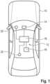
- Fig. 1shows a schematic representation of a motor vehicle 10 with an electronic vehicle guidance system 12.
- the electronic vehicle guidance system 12can comprise a longitudinal guidance system 14, a lateral guidance system 16, an evaluation device 18 and an environment sensor system with one or more sensors 20.
- the evaluation device 18can be designed to receive information from the longitudinal guidance system 14 and/or the lateral guidance system 16, which includes, for example, a current status of a respective one of the systems 14, 16.
- the evaluation device 18can be designed to receive information about the surroundings of a motor vehicle 10 from the sensors 20 of the environment sensor system.
- the sensors 20 or at least one of the sensors 20can be designed as a camera sensor 20, wherein the camera sensor 20 can be used to detect, for example, how far the motor vehicle 10 or at least one tire of the motor vehicle 10 is from a lane boundary line 22 at a predetermined point in time (see Fig. 2 ) is removed.
- the evaluation device 18can, for example, have a computing unit that can be designed to calculate a probability for a further journey of the motor vehicle 10 on the basis of the information from the longitudinal guidance system 14, the lateral guidance system 16 and/or the other described information.
- the computing unitcan execute a computer program that contains the corresponding commands.
- Fig. 2shows a schematic representation of an example lane change situation.
- the motor vehicle 10 or the driver's own vehicleis traveling along the driver's own lane 24.
- the longitudinal guidance system 14 of the motor vehicle 10can, for example, adapt a current driving speed of the motor vehicle 10 to a first target object 26, wherein the first target object 26 in the present example is a foreign vehicle that is traveling in front of the driver's own vehicle 10 along the driver's own lane 24.
- the dashed line 28is in Fig. 2 a driving trajectory 28 of the motor vehicle 10 is indicated, which will be traveled during a lane change of the motor vehicle 10 from the own lane 24 to the adjacent target lane 30.
- Another motor vehicle 32is traveling along a target lane 30, which can be selected by the evaluation device 18 as a new target object 32 for the motor vehicle 10 as soon as it is traveling along the target lane 30.
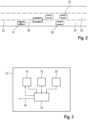
- Fig. 3shows a schematic representation of an electronic vehicle guidance system 12 according to an embodiment of the invention.
- the electronic vehicle guidance system 12here includes a longitudinal guidance system 14, a lateral guidance system 16, further sensors 20 of an environment sensor system of the motor vehicle 10 and an evaluation device 18.
- the evaluation device 18can receive information from the longitudinal guidance system 14 or from the lateral guidance system 16 regarding a respective status of a respective one of the systems 14, 16.
- the evaluation device 18can receive information from the sensors 20 of the environment sensor system of the motor vehicle 10 regarding a vehicle environment of the motor vehicle 10, wherein the information influences the determination of the probability that the motor vehicle 10 will return to the own lane 24 during the further course of the journey after aborting a lane change process.
- the evaluation device 18can make a suggestion to the longitudinal guidance system 14 that the first target object 26 along the own lane 24 should be selected again as the new target object.
- the evaluation device 18can make no suggestion regarding a target object to be selected if the determined probability falls below the predetermined limit value. The latter case is in Fig. 3 schematically shown by the arrow 34.
- Fig. 4shows a schematic representation of a method for selecting a target object 26, 32 for a longitudinal guidance system 14 of a motor vehicle 10.
- at least one driving parameter of the motor vehicle 10is adapted by the longitudinal guidance system 14 depending on the selected target object 26, 32.
- step S1the motor vehicle 10 is initially operated along its own lane 24, wherein the at least one driving parameter of the motor vehicle 10 is adjusted by the longitudinal guidance system 14 depending on a first target object 26 which is traveling in front of the motor vehicle 10 along its own lane 24 in the direction of travel.
- step S2an at least partially automated lane change process for the motor vehicle 10 is initiated by a lateral guidance system 16 of the motor vehicle 10, wherein the lane change process includes a change of the motor vehicle 10 from its own lane 24 to a target lane 30 arranged adjacent to its own lane 24.
- the lane change processincludes a change from the first target object 26 to a second target object 32, wherein the second target object 32 is arranged in front of the motor vehicle 10 along the target lane 30 in the direction of travel.
- the lane change processis aborted by the lateral guidance system 16. This can be due, for example, to the fact that the environment sensor system of the motor vehicle 10 detects that another motor vehicle is approaching from behind along the target lane 30 at a greatly excessive speed.
- the evaluation device 18 of the motor vehicle 10determines a probability that the motor vehicle 10 will return to the own lane 24 during the further course of the journey. Depending on the probability determined, three possible proposal options arise for the evaluation device 18 in the example shown. If the probability determination shows that the motor vehicle 10 is unlikely to return to the own lane 24 during the further course of the journey, the second target object 32 is retained as the target object in a step S5.
- the first target object 26is again selected as the target object in a step S6.
- the target object selectioncan be omitted in a step S7. This can be useful, for example, if no clear probability can be determined.
- the method step S7can alternatively or additionally include informing a driver of the motor vehicle 10 that no target object is currently selected for the longitudinal guidance system 14. Alternatively or additionally, the driver can then manually select one of the possible target objects 26, 32 for the longitudinal guidance system 14, for example using a touch control gesture of a touch screen in an interior of the motor vehicle 10.
- Fig. 5shows a schematic representation of a method for operating a motor vehicle 10.
- steps S1 to S5 or S1 to S6 or S1 to S7are summarized by method step S8.
- a method step S9according to the target object selection as made in step S8, a command for adapting the at least one driving parameter to the selected target object 26, 32 is generated.
Landscapes
- Engineering & Computer Science (AREA)
- Transportation (AREA)
- Mechanical Engineering (AREA)
- Automation & Control Theory (AREA)
- Chemical & Material Sciences (AREA)
- Combustion & Propulsion (AREA)
- Physics & Mathematics (AREA)
- Mathematical Physics (AREA)
- Human Computer Interaction (AREA)
- Traffic Control Systems (AREA)
- Control Of Position, Course, Altitude, Or Attitude Of Moving Bodies (AREA)
Abstract
Translated fromGerman
Description
Translated fromGermanDie Erfindung betrifft ein Verfahren zur Auswahl eines Zielobjekts für ein Längsführungssystem eines Kraftfahrzeugs. Durch das Längsführungssystem kann zumindest ein Fahrparameter des Kraftfahrzeugs, beispielsweise eine aktuell gefahrene Fahrtgeschwindigkeit des Kraftfahrzeugs, in Abhängigkeit von dem ausgewählten Zielobjekt angepasst werden. Bei dem Zielobjekt kann es sich beispielsweise um ein anderes Kraftfahrzeug handeln, welches dem Kraftfahrzeug oder Eigenfahrzeug entlang einer Eigenfahrspur vorausfährt. Das Längsführungssystem, welches beispielsweise ein automatisches Abstandhaltesystem des Kraftfahrzeugs sein kann, kann als Bestandteil eines elektronischen Fahrzeugführungssystems des Kraftfahrzeugs ausgebildet sein. Weitere Aspekte der Erfindung betreffen ein solches elektronisches Fahrzeugführungssystem sowie ein Kraftfahrzeug mit einem solchen System.The invention relates to a method for selecting a target object for a longitudinal guidance system of a motor vehicle. The longitudinal guidance system can be used to adapt at least one driving parameter of the motor vehicle, for example a current driving speed of the motor vehicle, depending on the selected target object. The target object can be, for example, another motor vehicle that is driving ahead of the motor vehicle or the driver's own vehicle along a lane of its own. The longitudinal guidance system, which can be, for example, an automatic distance keeping system of the motor vehicle, can be designed as a component of an electronic vehicle guidance system of the motor vehicle. Further aspects of the invention relate to such an electronic vehicle guidance system and a motor vehicle with such a system.
Moderne Kraftfahrzeuge weisen in der Regel ein Längsführungssystem und ein Querführungssystem auf, wobei durch das Längsführungssystem Aktionen des Kraftfahrzeugs gesteuert werden können, die seine Bewegung in Längsrichtung beziehungsweise parallel zur Fahrzeuglängsrichtung betreffen. Durch das Querführungssystem hingegen können solche Aktionen des Kraftfahrzeugs beeinflusst oder gesteuert werden, welche eine Bewegung des Kraftfahrzeugs entlang einer Richtung quer zur beschriebenen Längsführungsrichtung betreffen. Längsführungssysteme können daher insbesondere Aktionen steuern, welche eine Beschleunigung und/oder ein Abbremsen des Kraftfahrzeugs betreffen, während Querführungssysteme hauptsächlich solche Aktionen des Kraftfahrzeugs steuern, welche eine Lenkbewegung des Kraftfahrzeugs betreffen.Modern motor vehicles generally have a longitudinal guidance system and a transverse guidance system, whereby the longitudinal guidance system can control actions of the motor vehicle that affect its movement in the longitudinal direction or parallel to the vehicle's longitudinal direction. The transverse guidance system, on the other hand, can influence or control actions of the motor vehicle that affect a movement of the motor vehicle along a direction transverse to the described longitudinal guidance direction. Longitudinal guidance systems can therefore in particular control actions that affect acceleration and/or braking of the motor vehicle, while transverse guidance systems mainly control actions of the motor vehicle that affect a steering movement of the motor vehicle.
Ein bekanntes Beispiel für ein Längsführungssystem besteht in einem automatischen Abstandhaltesystem oder ACC-System (ACC: automatic cruise control). Ein solches System sorgt dafür, dass ein vorbestimmter Abstand zwischen dem Kraftfahrzeug und einem vorausfahrenden Kraftfahrzeug, welches als Zielobjekt für das Längsführungssystem ausgewählt werden kann, nicht unterschritten wird.A well-known example of a longitudinal guidance system is an automatic distance control system or ACC system (ACC: automatic cruise control). Such a system ensures that a predetermined distance is not exceeded between the motor vehicle and a motor vehicle driving ahead, which can be selected as a target object for the longitudinal guidance system.
Außerdem ist es bekannt, dass durch ein Querführungssystem eines Kraftfahrzeugs ein zumindest teilweise automatisiert durchgeführter Fahrspurwechsel initiiert werden kann. Ein solcher Fahrspurwechsel kann beispielsweise durch das Betätigen eines Blinkers ausgelöst werden. Im Zuge eines solchen Fahrspurwechsels oder Spurwechselvorgangs, bei dem das Kraftfahrzeug von der Eigenfahrspur auf eine zu der Eigenfahrspur benachbart angeordnete Zielfahrspur wechselt, kann für das beschriebene Längsführungssystem ein neues Zielobjekt entlang der Zielfahrspur ausgewählt werden. Mit anderen Worten wird also ab der Initiierung des Spurwechselvorgangs ein Verhalten des Kraftfahrzeugs nicht mehr in Abhängigkeit von einem bislang ausgewählten Zielobjekt entlang der Eigenfahrspur angepasst, sondern in Abhängigkeit von dem neuen Zielobjekt entlang der Zielfahrspur.It is also known that a lateral guidance system of a motor vehicle can initiate an at least partially automated lane change. Such a lane change can be triggered, for example, by activating a turn signal. During such a lane change or lane change process, in which the motor vehicle changes from its own lane to a target lane adjacent to its own lane, a new target object along the target lane can be selected for the longitudinal guidance system described. In other words, from the initiation of the lane change process, the behavior of the motor vehicle is no longer adapted depending on a previously selected target object along its own lane, but rather depending on the new target object along the target lane.
Aus der
Eine Aufgabe der vorliegenden Erfindung besteht darin, eine allgemeine Verkehrssicherheit zu erhöhen. Insbesondere soll die Zielobjektauswahl im Zusammenhang mit abgebrochenen oder unterbrochenen Spurwechselvorgängen gegenüber den bekannten Verfahren verbessert, insbesondere beschleunigt werden.One object of the present invention is to increase general traffic safety. In particular, the target object selection in connection with aborted or interrupted lane changing processes should be improved, in particular accelerated, compared to the known methods.
Die Aufgabe wird durch die Gegenstände der unabhängigen Patentansprüche gelöst. Vorteilhafte Weiterbildungen der Erfindung sind durch die abhängigen Patentansprüche, die folgende Beschreibung sowie die Figuren beschrieben.The object is achieved by the subject matter of the independent patent claims. Advantageous developments of the invention are described by the dependent patent claims, the following description and the figures.
Durch die Erfindung ist ein Verfahren zur Auswahl eines Zielobjekts für ein Längsführungssystem eines Kraftfahrzeugs bereitgestellt. Durch das Längsführungssystem wird zumindest ein Fahrparameter des Kraftfahrzeug in Abhängigkeit von dem ausgewählten Zielobjekt angepasst. Wie eingangs erwähnt, kann es sich bei dem Zielobjekt um ein dem Kraftfahrzeug vorausfahrendes anderes Kraftfahrzeug handeln. Beispielsweise kann durch das Längsführungssystem derart in eine Längsführung des Kraftfahrzeugs eingegriffen werden, dass das Kraftfahrzeug seine aktuelle Fahrtgeschwindigkeit an einem zu dem vorausfahrenden Kraftfahrzeug einzuhaltenden Abstand orientiert oder diesem anpasst.The invention provides a method for selecting a target object for a longitudinal guidance system of a motor vehicle. The longitudinal guidance system adjusts at least one driving parameter of the motor vehicle depending on the selected target object. As mentioned at the beginning, the target object can be another motor vehicle driving ahead of the motor vehicle. For example, the longitudinal guidance system can intervene in the longitudinal guidance of the motor vehicle in such a way that that the motor vehicle orientates or adapts its current driving speed to a distance to be maintained from the motor vehicle in front.
Gemäß dem hier beschriebenen Verfahren wird das Kraftfahrzeug zunächst entlang einer Eigenfahrspur betrieben. Mit anderen Worten fährt das Kraftfahrzeug also zunächst auf der Eigenfahrspur. Hierbei wird der zumindest eine Fahrparameter des Kraftfahrzeugs durch das Längsführungssystem in Abhängigkeit von einem ersten Zielobjekt angepasst, welches in Fahrtrichtung vor dem Kraftfahrzeug entlang der Eigenfahrspur angeordnet ist. Mit anderen Worten kann es sich bei dem Zielobjekt um ein anderes Kraftfahrzeug handeln, welches in derselben Fahrspur wie das Eigenfahrzeug fährt, wobei beispielsweise ein vorbestimmter Abstand zwischen den Kraftfahrzeugen eingehalten werden soll.According to the method described here, the motor vehicle is initially operated along its own lane. In other words, the motor vehicle initially drives in its own lane. The at least one driving parameter of the motor vehicle is adjusted by the longitudinal guidance system depending on a first target object that is arranged in front of the motor vehicle along its own lane in the direction of travel. In other words, the target object can be another motor vehicle that is driving in the same lane as the vehicle itself, whereby, for example, a predetermined distance between the motor vehicles should be maintained.
Verfahrensgemäß wird dann durch ein Querführungssystem des Kraftfahrzeugs bzw. Eigenfahrzeugs ein zumindest teilautomatisierter Spurwechselvorgang für das Kraftfahrzeug initiiert. Dies kann beispielsweise auf Veranlassung eines Fahrers des Kraftfahrzeugs erfolgen, welcher beispielsweise zum Einleiten des Spurwechselvorgangs einen Blinker betätigen kann. Der derart eingeleitete Spurwechselvorgang beinhaltet einen Wechsel des Kraftfahrzeugs von der Eigenfahrspur auf eine zu der Eigenfahrspur benachbart angeordnete Zielfahrspur. Der Spurwechselvorgang beinhaltet außerdem einen Wechsel von dem ersten Zielobjekt hin zu einem zweiten Zielobjekt, welches sich in Fahrtrichtung vor dem Kraftfahrzeug zumindest teilweise entlang der Zielfahrspur befindet. Bevorzugt befindet sich das zweite Zielobjekt vollständig entlang der Zielfahrspur. Allerdings können Situationen auftreten, in denen sich nur ein Teil, insbesondere ein überwiegender Teil, des zweiten Zielobjekts entlang der Zielfahrspur befindet. Eine solche Situation tritt zum Beispiel dann auf, wenn es sich bei dem zweiten Zielobjekt um einen überbreiten Lastwagen oder Ähnliches handelt, der zwar entlang der Zielfahrspur fährt, aufgrund seiner Breite aber über die Begrenzungen der Zielfahrspur hinausragt.According to the method, an at least partially automated lane change process for the motor vehicle is then initiated by a lateral guidance system of the motor vehicle or the driver's own vehicle. This can be done, for example, at the instigation of a driver of the motor vehicle, who can, for example, activate a turn signal to initiate the lane change process. The lane change process initiated in this way involves the motor vehicle changing from the driver's own lane to a target lane adjacent to the driver's own lane. The lane change process also includes a change from the first target object to a second target object which is located at least partially along the target lane in front of the motor vehicle in the direction of travel. The second target object is preferably located completely along the target lane. However, situations can arise in which only a part, in particular a predominant part, of the second target object is along the target lane. Such a situation occurs, for example, when the second target object is an over-wide truck or similar which is driving along the target lane but, due to its width, protrudes beyond the boundaries of the target lane.
Bevorzugt findet der Wechsel zu dem zweiten Zielobjekt bereits mit Beginn des Spurwechselvorgangs statt. Hierdurch kann erreicht werden, dass das Kraftfahrzeug beispielsweise seine Geschwindigkeit schon beim Spurwechselvorgang oder währenddessen an eine Fahrtgeschwindigkeit des zweiten oder neuen Zielobjekts anpasst.Preferably, the change to the second target object takes place at the beginning of the lane change process. This can ensure that the motor vehicle, for example, adapts its speed to the driving speed of the second or new target object during or during the lane change process.
Der beschriebene Spurwechselvorgang kann nun vor seinem Abschluss unterbrochen oder abgebrochen werden. Die Unterbrechung oder der Abbruch des Spurwechselvorgangs kann beispielsweise teilautomatisiert oder vollautomatisiert durch das Querführungssystem erfolgen, beispielsweise wenn erkannt wird, dass sich ein drittes Fahrzeug von hinten mit überhöhter Geschwindigkeit nähert. Der Spurwechselvorgang kann alternativ oder zusätzlich auch durch einen Lenkeingriff eines Fahrers des Eigenfahrzeugs abgebrochen oder unterbrochen werden.The lane change process described can now be interrupted or aborted before it is completed. The interruption or abort of the lane change process can, for example, be partially or fully automated by the lateral guidance system, for example, if it is detected that a third vehicle is approaching from behind at excessive speed. The lane change process can alternatively or additionally be aborted or interrupted by a steering intervention by a driver of the vehicle.
Falls der Spurwechselvorgang unterbrochen oder abgebrochen wird, wird erfindungsgemäß durch eine Bewertungseinrichtung eine Wahrscheinlichkeit dafür ermittelt, dass das Kraftfahrzeug im weiteren Fahrtverlauf in die Eigenfahrspur zurückkehrt. Bevorzugt findet die Wahrscheinlichkeitsermittlung zeitlich gemeinsam mit dem Abbruch oder mit der Unterbrechung des Spurwechselvorgangs statt. Bevorzugt findet also die Wahrscheinlichkeitsermittlung gleichzeitig mit dem Abbruch oder der Unterbrechung des Spurwechselvorgangs statt. Es kann also ohne oder mit nur geringer zeitlicher Verzögerung ermittelt werden, wie wahrscheinlich es ist, dass das Kraftfahrzeug infolge der Unterbrechung oder des Abbruchs des Spurwechselvorgangs in die Eigenfahrspur zurückkehrt. Erfindungsgemäß wird in Abhängigkeit von der ermittelten Wahrscheinlichkeit für den weiteren Fahrtverlauf entweder das zweite Zielobjekt beibehalten, oder erneut das erste Zielobjekt ausgewählt, oder kein Zielobjekt für das Längsführungssystem ausgewählt.If the lane change process is interrupted or aborted, according to the invention an evaluation device determines the probability that the motor vehicle will return to its own lane during the rest of the journey. The probability determination preferably takes place at the same time as the lane change process is aborted or interrupted. The probability determination therefore preferably takes place at the same time as the lane change process is aborted or interrupted. It is therefore possible to determine with little or no time delay how likely it is that the motor vehicle will return to its own lane as a result of the lane change process being interrupted or aborted. According to the invention, depending on the probability determined for the rest of the journey, either the second target object is retained, or the first target object is selected again, or no target object is selected for the longitudinal guidance system.
Durch die Erfindung ergibt sich der Vorteil, dass nicht unnötig lange trotz abgebrochenem Spurwechselvorgang auf ein Zielobjekt in der ehemaligen Zielfahrspur geregelt wird. Vielmehr kann bei der entsprechenden Wahrscheinlichkeit direkt wieder auf das Zielobjekt entlang der ursprünglichen Eigenfahrspur geregelt werden. Hierdurch wird ein Verkehrsfluss verbessert und eine allgemeine Verkehrssicherheit erhöht.The invention has the advantage that the system does not control for an unnecessarily long time to a target object in the former target lane despite the lane change process being aborted. Instead, if the probability is high enough, the system can control directly to the target object along the original lane. This improves traffic flow and increases general traffic safety.
Zu der Erfindung gehören auch Ausführungsformen, durch die sich zusätzliche Vorteile ergeben.The invention also includes embodiments which provide additional advantages.
Eine Ausführungsform sieht vor, dass die Wahrscheinlichkeit in Abhängigkeit von einem aktuellen Status des Längsführungssystems des Kraftfahrzeugs beim Unterbrechen oder Abbrechen des Spurwechselvorgangs und/oder in Abhängigkeit von einem aktuellen Status des Querführungssystems des Kraftfahrzeugs beim Unterbrechen oder Abbrechen des Spurwechselvorgangs ermittelt wird. Mit anderen Worten kann zum Ermitteln der Wahrscheinlichkeit ein Informationsaustausch zwischen dem Längs- und dem Querführungssystem stattfinden. Die Bewertungseinrichtung kann also von dem Längsführungssystem und/oder von dem Querführungssystem eine Information betreffend einen jeweiligen Status eines der Systeme empfangen und zur Ermittlung der Wahrscheinlichkeit auswerten. Der Status des Längsführungssystems kann beispielsweise eine Information darüber beinhalten, ob das Längsführungssystem beim Unterbrechen oder beim Abbruch des Spurwechselvorgangs aktiv oder inaktiv war. Außerdem kann der Status des Längsführungssystems beinhalten, auf welches Zielobjekt das Längsführungssystem zum Zeitpunkt des Unterbrechens oder des Abbrechens des Spurwechselvorgangs ausgerichtet oder eingestellt war. Beispielsweise kann einem jeweiligen Status oder einer jeweiligen Information, die in einem jeweiligen Status beinhaltet ist, ein vorbestimmter Wahrscheinlichkeitswert zugeordnet werden. Die Bewertungseinrichtung kann dann auf Basis der Wahrscheinlichkeitswerte und mittels eines Algorithmus die Gesamtwahrscheinlichkeit für das Verbleiben oder für das erneute Wechseln (Zurückwechseln) des Kraftfahrzeugs in die Eigenfahrspur ermitteln.One embodiment provides that the probability is determined depending on a current status of the longitudinal guidance system of the motor vehicle when the lane change process is interrupted or aborted and/or depending on a current status of the lateral guidance system of the motor vehicle when the lane change process is interrupted or aborted. In other words, an exchange of information between the longitudinal and lateral guidance systems can take place to determine the probability. The evaluation device can therefore receive information from the longitudinal guidance system and/or from the lateral guidance system regarding a respective status of one of the systems and evaluate it to determine the probability. The status of the longitudinal guidance system can, for example, be a Include information about whether the longitudinal guidance system was active or inactive when the lane change process was interrupted or aborted. In addition, the status of the longitudinal guidance system can include which target object the longitudinal guidance system was aimed at or set at the time the lane change process was interrupted or aborted. For example, a predetermined probability value can be assigned to a respective status or to a respective piece of information contained in a respective status. The evaluation device can then use the probability values and an algorithm to determine the overall probability of the motor vehicle remaining in or changing back into its own lane.
Bevorzugt beinhaltet der aktuelle Status des Querführungssystems zumindest eine Information zu einem aktuell von dem Querführungssystem geforderten Lenkmoment. Dabei kann das aktuell geforderte Lenkmoment ein Zurücklenken des Kraftfahrzeugs in Richtung der Eigenfahrspur umfassen. Eine derartige Information, also eine Information über ein aktuelles Lenkmoment des Querführungssystems, welches zurück in die Eigenfahrspur führt, kann einen vergleichsweise hohen Wahrscheinlichkeitswert dafür aufweisen, dass das Kraftfahrzeug im weiteren Fahrtverlauf in die Eigenfahrspur zurückkehrt. In der Folge kann die Bewertungseinrichtung entscheiden, dass erneut das erste Zielobjekt für den weiteren Fahrtverlauf ausgewählt wird. Das aktuell von dem Querführungssystem geforderte Lenkmoment kann allerdings auch null betragen, mit anderen Worten kann kein systemseitiges Lenken mehr stattfinden. In diesem Fall kann beispielsweise auf Basis eines aktuellen Trägheitsmoments des Kraftfahrzeugs ermittelt werden, ob dieses sich wahrscheinlich weiter in Richtung der Zielfahrspur bewegen wird oder ob das Kraftfahrzeug wahrscheinlich wieder in die Eigenfahrspur zurückkehren wird.Preferably, the current status of the lateral guidance system contains at least information about a steering torque currently required by the lateral guidance system. The currently required steering torque can include steering the motor vehicle back in the direction of the vehicle's own lane. Such information, i.e. information about a current steering torque of the lateral guidance system that leads back into the vehicle's own lane, can have a comparatively high probability value that the motor vehicle will return to the vehicle's own lane as the journey continues. As a result, the evaluation device can decide that the first target object is selected again for the rest of the journey. However, the steering torque currently required by the lateral guidance system can also be zero, in other words, no more steering can take place on the system side. In this case, for example, it can be determined on the basis of a current moment of inertia of the motor vehicle whether it is likely to continue moving in the direction of the target lane or whether the motor vehicle is likely to return to the vehicle's own lane.
Insbesondere für den beschriebenen Fall, wonach keine systemseitige Lenkung durch das Querführungssystem mehr stattfindet, kann es vorteilhaft sein, zusätzlich eine aktuelle Fahrbahnkrümmung der Fahrbahn entlang der Eigenfahrspur und/oder entlang der Zielfahrspur oder auch eine Fahrbahnquerneigung der Fahrbahn entlang der Eigenfahrspur und/oder der Zielfahrspur zur Ermittlung der Wahrscheinlichkeit bereitzustellen. Anhand dieser Faktoren kann die Wahrscheinlichkeit ermittelt werden, dass das Kraftfahrzeug auch ohne systemseitiges Lenken in die Eigenfahrspur zurückkehrt. Die aktuelle Fahrbahnquerneigung kann dabei mittels eines Inertial Measurement Unit (IMU) des Kraftfahrzeugs ermittelt werden. Die aktuelle Fahrbahnkrümmung kann beispielsweise auch anhand einer in einem Navigationssystem des Kraftfahrzeugs abgespeicherten digitalen Karte bekannt sein. Mit anderen Worten können die beschriebenen Informationen aus anderen Fahrzeugsystemen, welche Teile eines Umfeldsensorsystems des Kraftfahrzeugs sein können, bereitgestellt werden.In particular, for the case described, where no more system-side steering is carried out by the lateral guidance system, it can be advantageous to additionally provide a current curvature of the road along the vehicle's own lane and/or along the target lane or a transverse inclination of the road along the vehicle's own lane and/or the target lane to determine the probability. Using these factors, the probability can be determined that the motor vehicle will return to its own lane even without system-side steering. The current transverse inclination of the road can be determined using an inertial measurement unit (IMU) of the motor vehicle. The current curvature of the road can also be known, for example, from a digital map stored in a navigation system of the motor vehicle. In other words, the described information from other vehicle systems, which may be parts of an environmental sensor system of the motor vehicle.
Alternativ oder zusätzlich kann auch ein aktuelles Fahrerlenkmoment erfasst werden. Das Fahrerlenkmoment beschreibt, ob und wie ein Fahrer des Kraftfahrzeugs manuell in eine Lenkung des Kraftfahrzeugs eingreift. Das Fahrerlenkmoment kann beispielsweise anhand eines Lenkmomentsensors oder auch anhand einer Fahrerbeobachtung, beispielsweise durch Kameras im Fahrzeuginnenraum, erfolgen. Lenkt der Fahrer beispielsweise aktiv wieder in Richtung der Eigenfahrspur, so kann die Bewertungseinrichtung als Wahrscheinlichkeit dafür, dass das Kraftfahrzeug im weiteren Fahrtverlauf in die Eigenfahrspur zurückkehrt, einen Wert von nahe 100% ansetzen. Eine derart hohe Wahrscheinlichkeit wird dazu führen, dass erneut das erste Zielobjekt für das Fahrzeuglängsführungssystem ausgewählt wird.Alternatively or additionally, a current driver steering torque can also be recorded. The driver steering torque describes whether and how a driver of the motor vehicle manually intervenes in the steering of the motor vehicle. The driver steering torque can be determined, for example, using a steering torque sensor or by observing the driver, for example using cameras in the vehicle interior. If the driver actively steers back towards the own lane, for example, the evaluation device can set a value of almost 100% as the probability that the motor vehicle will return to the own lane during the rest of the journey. Such a high probability will result in the first target object being selected again for the vehicle longitudinal guidance system.
Durch die zusätzliche Berücksichtigung der hier genannten Faktoren wird eine Wahrscheinlichkeitsermittlung in vorteilhafter Weise weiter verbessert.By additionally taking the factors mentioned here into account, probability determination is further improved in an advantageous manner.
Alternativ oder zusätzlich kann auch anhand einer für das Kraftfahrzeug bereitgestellten Routennavigation die Wahrscheinlichkeit für ein Zurückwechseln des Kraftfahrzeugs in die Eigenfahrspur ermittelt werden. Ist gemäß der Routennavigation beispielsweise vorgesehen, dass das Kraftfahrzeug eine Autobahnausfahrt nehmen soll, die sich in wenigen hundert Metern vor dem Kraftfahrzeug befindet und wird ein Überholvorgang abgebrochen, so kann ein vergleichsweise hoher Wahrscheinlichkeitswert dafür ermittelt werden, dass das Kraftfahrzeug in die Eigenfahrspur zurückwechselt. Der hohe Wahrscheinlichkeitswert kann beispielsweise über 70 oder 75% betragen.Alternatively or additionally, the probability of the vehicle changing back to its own lane can also be determined using route navigation provided for the vehicle. For example, if the route navigation specifies that the vehicle should take a motorway exit that is located a few hundred meters ahead of the vehicle and an overtaking maneuver is aborted, a comparatively high probability value can be determined that the vehicle will change back to its own lane. The high probability value can be over 70 or 75%, for example.
Alternativ oder zusätzlich kann die Wahrscheinlichkeit auch in Abhängigkeit von einem Abstand und/oder in Abhängigkeit von einer Änderung des Abstands ermittelt werden, der beim Unterbrechen oder Abbrechen des Spurwechselvorgangs zwischen zumindest einem Reifen des Kraftfahrzeugs und einer Trennlinie zwischen der Eigenfahrspur und der Zielfahrspur besteht. Unter einer Trennlinie im Zusammenhang mit der vorliegenden Erfindung ist insbesondere eine Fahrbahnmarkierung zu verstehen, welche für eine optische Trennung zwischen der Eigenfahrspur und der Zielfahrspur sorgt. Der beschriebene Abstand oder die sogenannte distance to line crossing (DLC) ist demnach ein Indikator für die Wahrscheinlichkeit, dass das Eigenfahrzeug in die Eigenfahrspur zurückkehrt oder nicht. Ganz generell kann einem größeren Abstand eine höhere Wahrscheinlichkeit dafür zugeordnet werden, dass das Kraftfahrzeug in der Eigenfahrspur verbleibt oder in diese zurückkehrt. Wird der Spurwechselvorgang jedoch erst bei einem kleineren Abstand oder sogar erst bei einem teilweisen Überqueren der Trennlinie abgebrochen, so ist die Wahrscheinlichkeit dafür, dass das Eigenfahrzeug in die Eigenfahrspur zurückkehrt, vergleichsweise geringer.Alternatively or additionally, the probability can also be determined as a function of a distance and/or as a function of a change in the distance that exists when the lane change process is interrupted or aborted between at least one tire of the motor vehicle and a dividing line between the own lane and the target lane. A dividing line in the context of the present invention is to be understood in particular as a lane marking that provides a visual separation between the own lane and the target lane. The distance described or the so-called distance to line crossing (DLC) is therefore an indicator of the probability that the own vehicle will return to the own lane or not. In general, a greater distance can be assigned a higher probability that the motor vehicle will remain in the own lane or return to it. If the However, if the lane change is only aborted when there is a smaller distance or even only when the dividing line is partially crossed, the probability that the vehicle will return to the lane is comparatively lower.
Bevorzugt kann die Wahrscheinlichkeit also auch in Abhängigkeit davon ermittelt werden, ob und insbesondere in welchem Ausmaß das Kraftfahrzeug die Trennlinie beim Unterbrechen oder Abbrechen des Spurwechselvorgang bereits zumindest teilweise überquert hat.Preferably, the probability can also be determined depending on whether and in particular to what extent the motor vehicle has already at least partially crossed the dividing line when interrupting or aborting the lane change process.
Eine weitere Ausführungsform sieht vor, dass mittels einer Benutzerschnittstelle des Kraftfahrzeugs eine Aufforderung an einen Fahrer des Kraftfahrzeugs bereitgestellt wird, das ausgewählte Zielobjekt zu bestätigen. Mit anderen Worten kann die Bewertungseinrichtung das ausgewählte Zielobjekt für den Fahrer zur Auswahl stellen. Die Benutzerschnittstelle kann dabei beispielsweise eine graphische Oberfläche, beispielsweise einen Bildschirm im Kraftfahrzeuginnenraum, umfassen, wobei der Fahrer mittels Touch-Bedienung eines von mehreren auf dem Bildschirm dargestellten Zielobjekten auswählen kann. Alternativ oder zusätzlich kann die Darstellung auf einem Kombiinstrument des Kraftfahrzeugs, beispielsweise auf einem Display hinter dem Lenkrad des Kraftfahrzeugs, erfolgen.A further embodiment provides that a user interface of the motor vehicle is used to provide a request to a driver of the motor vehicle to confirm the selected target object. In other words, the evaluation device can make the selected target object available for selection for the driver. The user interface can comprise, for example, a graphical interface, for example a screen in the interior of the motor vehicle, whereby the driver can select one of several target objects shown on the screen using touch operation. Alternatively or additionally, the display can take place on an instrument cluster of the motor vehicle, for example on a display behind the steering wheel of the motor vehicle.
Für Anwendungsfälle oder Anwendungssituationen, die sich bei dem Verfahren ergeben können und die hier nicht explizit beschrieben sind, kann vorgesehen sein, dass gemäß dem Verfahren eine Fehlermeldung und/oder eine Aufforderung zur Eingabe einer Nutzerrückmeldung ausgegeben und/oder eine Standardeinstellung und/oder ein vorbestimmter Initialzustand eingestellt werden.For use cases or application situations that may arise during the method and which are not explicitly described here, it may be provided that, in accordance with the method, an error message and/or a request to enter user feedback is issued and/or a default setting and/or a predetermined initial state is set.
Ein weiterer Aspekt der Erfindung betrifft ein Fahrzeugführungssystem zum zumindest teilweise automatisierten Betreiben eines Kraftfahrzeugs mit einem Querführungssystem, einem Längsführungssystem und einer Bewertungseinrichtung, wobei das elektronische Fahrzeugführungssystem dazu ausgebildet ist, ein Ausführungsform des erfindungsgemäßen Verfahrens durchzuführen.A further aspect of the invention relates to a vehicle guidance system for the at least partially automated operation of a motor vehicle with a lateral guidance system, a longitudinal guidance system and an evaluation device, wherein the electronic vehicle guidance system is designed to carry out an embodiment of the method according to the invention.
Ein weiterer Aspekt der Erfindung betrifft ein Kraftfahrzeug mit einem solchen elektronischen Fahrzeugführungssystem.A further aspect of the invention relates to a motor vehicle with such an electronic vehicle guidance system.
Ein weiterer Aspekt der Erfindung betrifft ein Verfahren zum zumindest teilautomatisierten Betreiben eines Kraftfahrzeugs mittels eines elektronischen Fahrzeugführungssystems, wobei in Abhängigkeit von der Zielobjektauswahl ein Befehl zum Anpassen des zumindest einen Fahrparameters an das ausgewählte Zielobjekt erzeugt wird.A further aspect of the invention relates to a method for the at least partially automated operation of a motor vehicle by means of an electronic vehicle guidance system, wherein Depending on the target object selection, a command is generated to adapt the at least one driving parameter to the selected target object.
Zu der Erfindung gehören auch Weiterbildungen der weiteren erfindungsgemäßen Aspekte, die Merkmale aufweisen, wie sie bereits im Zusammenhang mit den Weiterbildungen des erfindungsgemäßen Verfahrens beschrieben worden sind. Aus diesem Grund sind die entsprechenden Weiterbildungen der weiteren erfindungsgemäßen Aspekte hier nicht noch einmal beschrieben.The invention also includes further developments of the other aspects of the invention, which have features as have already been described in connection with the further developments of the method according to the invention. For this reason, the corresponding further developments of the other aspects of the invention are not described again here.
Die Erfindung umfasst auch die Kombinationen der Merkmale der beschriebenen Ausführungsformen.The invention also includes combinations of the features of the described embodiments.
Im Folgenden werden Ausführungsbeispiele der Erfindung beschrieben. Hierzu zeigt:
- Fig. 1
- eine schematische Darstellung eines Kraftfahrzeugs mit einem elektronischen Fahrzeugführungssystem;
- Fig. 2
- eine schematische Darstellung einer beispielhaften Spurwechselsituation;
- Fig. 3
- eine schematische Darstellung eines elektronischen Fahrzeugführungssystems;
- Fig. 4
- eine schematische Darstellung eines Verfahrens zum Auswählen eines Zielobjekts für ein Längsführungssystem eines Kraftfahrzeugs; und
- Fig. 5
- eine schematische Darstellung eines Verfahrens zum Betreiben eines Kraftfahrzeugs.
- Fig. 1
- a schematic representation of a motor vehicle with an electronic vehicle guidance system;
- Fig. 2
- a schematic representation of an example lane change situation;
- Fig. 3
- a schematic representation of an electronic vehicle guidance system;
- Fig. 4
- a schematic representation of a method for selecting a target object for a longitudinal guidance system of a motor vehicle; and
- Fig. 5
- a schematic representation of a method for operating a motor vehicle.
Bei den im Folgenden erläuterten Ausführungsbeispielen handelt es sich um bevorzugte Ausführungsbeispiele der Erfindung. Bei den Ausführungsbeispielen stellen die beschriebenen Komponenten jeweils einzelne, unabhängig voneinander zu betrachtende Merkmale der Erfindung dar, welche die Erfindung jeweils auch unabhängig voneinander weiterbilden und damit auch einzeln oder in einer anderen als der gezeigten Kombination als Bestandteil der Erfindung anzusehen sind. Des Weiteren sind die beschriebenen Ausführungsbeispiele auch durch weitere der bereits beschriebenen Merkmale der Erfindung ergänzbar.The embodiments explained below are preferred embodiments of the invention. In the embodiments, the components described each represent individual features of the invention that are to be considered independently of one another, which also develop the invention independently of one another and are therefore to be viewed as part of the invention individually or in a combination other than that shown. Furthermore, the embodiments described can also be supplemented by other features of the invention already described.
In den Figuren sind funktionsgleiche Elemente jeweils mit denselben Bezugszeichen versehen.In the figures, functionally identical elements are provided with the same reference symbols.
Die Bewertungseinrichtung 18 kann dazu ausgebildet sein, Informationen von dem Längsführungssystem 14 und/oder dem Querführungssystem 16 zu empfangen, welche beispielsweise einen aktuellen Status eines jeweiligen der Systeme 14, 16 beinhaltet. Außerdem kann die Bewertungseinrichtung 18 dazu ausgebildet sein, von den Sensoren 20 des Umfeldsensorsystems Informationen eines Umfelds eines Kraftfahrzeugs 10 zu empfangen. Beispielsweise können die Sensoren 20 oder zumindest einer der Sensoren 20 als ein Kamerasensor 20 ausgebildet sein, wobei mittels des Kamerasensors 20 beispielsweise erfasst werden kann, wie weit das Kraftfahrzeug 10 oder zumindest ein Reifen des Kraftfahrzeugs 10 zu einem vorbestimmten Zeitpunkt von einer Fahrbahnbegrenzungslinie 22 (siehe
Mit der gestrichelten Linie 28 ist in
In einem Verfahrensschritt S1 wird das Kraftfahrzeug 10 zunächst entlang einer Eigenfahrspur 24 betrieben, wobei der zumindest eine Fahrparameter des Kraftfahrzeugs 10 durch das Längsführungssystem 14 in Abhängigkeit von einem ersten Zielobjekt 26 angepasst wird, welches in Fahrtrichtung vor dem Kraftfahrzeug 10 entlang der Eigenfahrspur 24 fährt. In einem Schritt S2 wird durch ein Querführungssystem 16 des Kraftfahrzeugs 10 ein zumindest teilautomatisierter Spurwechselvorgang für das Kraftfahrzeug 10 initiiert, wobei der Spurwechselvorgang einen Wechsel des Kraftfahrzeugs 10 von der Eigenfahrspur 24 auf eine zu der Eigenfahrspur 24 benachbart angeordnete Zielfahrspur 30 beinhaltet. Außerdem beinhaltet der Spurwechselvorgang einen Wechsel von dem ersten Zielobjekt 26 hin zu einem zweiten Zielobjekt 32, wobei das zweite Zielobjekt 32 in Fahrtrichtung vor dem Kraftfahrzeug 10 entlang der Zielfahrspur 30 angeordnet ist.In a method step S1, the
In einem Verfahrensschritt S3 wird der Spurwechselvorgang durch das Querführungssystem 16 abgebrochen. Dies kann beispielsweise dadurch begründet sein, dass durch das Umfeldsensorsystem des Kraftfahrzeugs 10 erkannt wird, dass sich entlang der Zielfahrspur 30 von hinten ein weiteres Kraftfahrzeug mit einer stark überhöhten Geschwindigkeit annähert. In einem Schritt S4 wird daraufhin durch die Bewertungseinrichtung 18 des Kraftfahrzeugs 10 eine Wahrscheinlichkeit dafür ermittelt, dass das Kraftfahrzeug 10 im weiteren Fahrtverlauf in die Eigenfahrspur 24 zurückkehrt. In Abhängigkeit von der ermittelten Wahrscheinlichkeit ergeben sich im dargestellten Beispiel drei mögliche Vorschlagsoptionen für die Bewertungseinrichtung 18. Ergibt die Wahrscheinlichkeitsermittlung, dass das Kraftfahrzeug 10 wahrscheinlich im weiteren Fahrtverlauf nicht in die Eigenfahrspur 24 zurückkehren wird, so wird in einem Schritt S5 das zweite Zielobjekt 32 als Zielobjekt beibehalten. Ergibt die Wahrscheinlichkeitsermittlung jedoch, dass es wahrscheinlich ist, dass das Kraftfahrzeug 10 im weiteren Fahrtverlauf in die Eigenfahrspur 24 zurückkehrt, so wird in einem Schritt S6 erneut das erste Zielobjekt 26 als Zielobjekt ausgewählt. Alternativ kann in einem Schritt S7 die Zielobjektauswahl unterbleiben. Dies kann zum Beispiel dann sinnvoll sein, wenn keine eindeutige Wahrscheinlichkeit ermittelt werden kann. Der Verfahrensschritt S7 kann alternativ oder zusätzlich enthalten, dass einem Fahrer des Kraftfahrzeugs 10 mitgeteilt wird, dass aktuell kein Zielobjekt für das Längsführungssystem 14 ausgewählt ist. Alternativ oder zusätzlich kann der Fahrer dann beispielsweise anhand einer Berührungsbedienungsgeste eines Touchbildschirms in einem Innenraum des Kraftfahrzeugs 10 eines der möglichen Zielobjekte 26, 32 für das Längsführungssystem 14 manuell auswählen.In a method step S3, the lane change process is aborted by the
Insgesamt zeigen die Beispiele, wie ein verbessertes Auswahlverfahren zur Auswahl eines Zielobjekts für ein Längsführungssystem eines Kraftfahrzeugs bereitgestellt werden kann.Overall, the examples show how an improved selection procedure for selecting a target object for a longitudinal guidance system of a motor vehicle can be provided.
- 1010
- Kraftfahrzeugmotor vehicle
- 1212
- elektronisches Fahrzeugführungssystemelectronic vehicle guidance system
- 1414
- Längsführungssystemlongitudinal guide system
- 1616
- Querführungssystemlateral guidance system
- 1818
- Bewertungseinrichtungassessment facility
- 2020
- Sensorensensors
- 2222
- Trennlinie, Fahrbahnbegrenzungsliniedividing line, lane boundary line
- 2424
- Eigenfahrspurprivate lane
- 2626
- erstes Zielobjektfirst target object
- 2828
- Fahrtrajektoriedriving trajectory
- 3030
- Zielfahrspurtarget lane
- 3232
- zweites Zielobjektsecond target object
- 3434
- Pfeil (keine Zielobjektauswahl)arrow (no target object selection)
Claims (14)
Translated fromGermandadurch gekennzeichnet, dass
falls das Querführungssystem (16) den Spurwechselvorgang unterbricht oder abbricht,
characterized in that
if the lateral guidance system (16) interrupts or aborts the lane change process,
Applications Claiming Priority (1)
| Application Number | Priority Date | Filing Date | Title |
|---|---|---|---|
| DE102023204457.9ADE102023204457B3 (en) | 2023-05-12 | 2023-05-12 | Method for selecting a target object for a longitudinal guidance system of a motor vehicle, electronic vehicle guidance system for a motor vehicle and motor vehicle with an electronic vehicle guidance system |
Publications (1)
| Publication Number | Publication Date |
|---|---|
| EP4461613A1true EP4461613A1 (en) | 2024-11-13 |
Family
ID=90924683
Family Applications (1)
| Application Number | Title | Priority Date | Filing Date |
|---|---|---|---|
| EP24173427.6APendingEP4461613A1 (en) | 2023-05-12 | 2024-04-30 | Method for selecting a target object for a longitudinal guidance system of a motor vehicle, electronic vehicle guidance system for a motor vehicle and motor vehicle with an electronic vehicle guidance system |
Country Status (4)
| Country | Link |
|---|---|
| US (1) | US20240375661A1 (en) |
| EP (1) | EP4461613A1 (en) |
| CN (1) | CN118928399A (en) |
| DE (1) | DE102023204457B3 (en) |
Citations (7)
| Publication number | Priority date | Publication date | Assignee | Title |
|---|---|---|---|---|
| DE19637245A1 (en)* | 1996-09-13 | 1998-03-26 | Bosch Gmbh Robert | Adaptive vehicle speed regulating method for road system |
| DE102006043149A1 (en) | 2006-09-14 | 2008-03-27 | Bayerische Motoren Werke Ag | Integrated transverse and longitudinal guidance assistant for motor vehicle, has trajectory calculating unit to calculate lane change trajectory with given distance of vehicle traveling in front, during distance regulated travel of vehicle |
| DE102009033800A1 (en) | 2009-07-18 | 2010-03-25 | Daimler Ag | Driver assisting method for use during traffic lane change scheduling of vehicle i.e. car, from momentary to target lane, involves reducing distance of appropriate vehicle to target vehicles to distance after docking appropriate vehicle |
| US20160107687A1 (en)* | 2014-10-16 | 2016-04-21 | Toyota Jidosha Kabushiki Kaisha | Driving support apparatus for vehicle and driving support method |
| US20180345960A1 (en)* | 2017-06-06 | 2018-12-06 | Toyota Jidosha Kabushiki Kaisha | Lane change assist device |
| US20180357904A1 (en)* | 2017-06-09 | 2018-12-13 | Toyota Jidosha Kabushiki Kaisha | Driving assist apparatus |
| DE112018000174T5 (en) | 2017-03-07 | 2019-08-08 | Robert Bosch Gmbh | Action plan system and procedure for autonomous vehicles |
Family Cites Families (19)
| Publication number | Priority date | Publication date | Assignee | Title |
|---|---|---|---|---|
| JP3870911B2 (en)* | 2003-02-10 | 2007-01-24 | 日産自動車株式会社 | Lane departure prevention device |
| JP4062310B2 (en)* | 2005-02-07 | 2008-03-19 | 日産自動車株式会社 | Driving intention estimation device, vehicle driving assistance device, and vehicle equipped with vehicle driving assistance device |
| JP4525670B2 (en)* | 2006-11-20 | 2010-08-18 | トヨタ自動車株式会社 | Travel control plan generation system |
| JP4623057B2 (en)* | 2007-06-05 | 2011-02-02 | トヨタ自動車株式会社 | Moving area acquisition device for own vehicle |
| US20110190972A1 (en)* | 2010-02-02 | 2011-08-04 | Gm Global Technology Operations, Inc. | Grid unlock |
| US9165468B2 (en)* | 2010-04-12 | 2015-10-20 | Robert Bosch Gmbh | Video based intelligent vehicle control system |
| DE102013224303A1 (en)* | 2013-11-27 | 2015-05-28 | Robert Bosch Gmbh | Method and control unit for situation-dependent power steering in a lane departure warning for a vehicle |
| KR102329444B1 (en)* | 2014-07-04 | 2021-11-24 | 주식회사 만도모빌리티솔루션즈 | Control system of vehicle and method thereof |
| US9994221B2 (en)* | 2016-07-13 | 2018-06-12 | Toyota Motor Engineering & Manufacturing North America, Inc. | Presenting travel settings for selection of nearby vehicle to follow |
| DE102016214097A1 (en)* | 2016-07-29 | 2018-02-01 | Bayerische Motoren Werke Aktiengesellschaft | Method and device for carrying out an at least partially automated driving maneuver |
| JP6760204B2 (en)* | 2017-06-06 | 2020-09-23 | トヨタ自動車株式会社 | Steering support device |
| JP6653300B2 (en)* | 2017-09-15 | 2020-02-26 | 本田技研工業株式会社 | Vehicle control device, vehicle control method, and program |
| KR102751284B1 (en)* | 2019-08-12 | 2025-01-10 | 현대자동차주식회사 | Interactive autonomous driving system |
| DE102020204078A1 (en)* | 2019-11-27 | 2021-05-27 | Robert Bosch Gesellschaft mit beschränkter Haftung | Driver assistance system for motor vehicles |
| US11608067B2 (en)* | 2020-08-12 | 2023-03-21 | Honda Motor Co., Ltd. | Probabilistic-based lane-change decision making and motion planning system and method thereof |
| US11151880B1 (en)* | 2020-08-21 | 2021-10-19 | Toyota Motor Engineering & Manufacturing North America, Inc. | Systems and methods for providing guidance to vehicle drivers regarding predicted lane-change behavior of other vehicle drivers |
| US11794723B2 (en)* | 2020-10-08 | 2023-10-24 | Hyundai Mobis Co., Ltd. | Apparatus and method for controlling driving of vehicle |
| WO2023054195A1 (en)* | 2021-09-30 | 2023-04-06 | 株式会社デンソー | Vehicle control device and vehicle control program |
| JP7694546B2 (en)* | 2022-12-01 | 2025-06-18 | トヨタ自動車株式会社 | Active safety device and vehicle |
- 2023
- 2023-05-12DEDE102023204457.9Apatent/DE102023204457B3/enactiveActive
- 2024
- 2024-04-30EPEP24173427.6Apatent/EP4461613A1/enactivePending
- 2024-05-08USUS18/658,535patent/US20240375661A1/enactivePending
- 2024-05-09CNCN202410566655.9Apatent/CN118928399A/enactivePending
Patent Citations (7)
| Publication number | Priority date | Publication date | Assignee | Title |
|---|---|---|---|---|
| DE19637245A1 (en)* | 1996-09-13 | 1998-03-26 | Bosch Gmbh Robert | Adaptive vehicle speed regulating method for road system |
| DE102006043149A1 (en) | 2006-09-14 | 2008-03-27 | Bayerische Motoren Werke Ag | Integrated transverse and longitudinal guidance assistant for motor vehicle, has trajectory calculating unit to calculate lane change trajectory with given distance of vehicle traveling in front, during distance regulated travel of vehicle |
| DE102009033800A1 (en) | 2009-07-18 | 2010-03-25 | Daimler Ag | Driver assisting method for use during traffic lane change scheduling of vehicle i.e. car, from momentary to target lane, involves reducing distance of appropriate vehicle to target vehicles to distance after docking appropriate vehicle |
| US20160107687A1 (en)* | 2014-10-16 | 2016-04-21 | Toyota Jidosha Kabushiki Kaisha | Driving support apparatus for vehicle and driving support method |
| DE112018000174T5 (en) | 2017-03-07 | 2019-08-08 | Robert Bosch Gmbh | Action plan system and procedure for autonomous vehicles |
| US20180345960A1 (en)* | 2017-06-06 | 2018-12-06 | Toyota Jidosha Kabushiki Kaisha | Lane change assist device |
| US20180357904A1 (en)* | 2017-06-09 | 2018-12-13 | Toyota Jidosha Kabushiki Kaisha | Driving assist apparatus |
Also Published As
| Publication number | Publication date |
|---|---|
| US20240375661A1 (en) | 2024-11-14 |
| CN118928399A (en) | 2024-11-12 |
| DE102023204457B3 (en) | 2024-07-18 |
Similar Documents
| Publication | Publication Date | Title |
|---|---|---|
| EP1808350B1 (en) | Procedure for operating a longitudinal guiding system in a motor vehicle | |
| DE102013017209B4 (en) | Method for operating a driver assistance system of a motor vehicle and motor vehicle | |
| DE102011016770A1 (en) | Method for assisting vehicle driver for lane change from current lane to adjacent target lane, involves changing intervention into steering device, brake device and drive train if sufficient space for vehicle for lane change is established | |
| EP4112406B1 (en) | Method for carrying out a lane change on a slow-down lane by means of an assistance system, computer program product and assistance system | |
| DE102020117160B3 (en) | Method and vehicle system for operating a lane change assistant | |
| DE102011121260A1 (en) | A method for assisting a driver of a motor vehicle in the event of loss of attention with the aid of an error counter | |
| DE102009033800A1 (en) | Driver assisting method for use during traffic lane change scheduling of vehicle i.e. car, from momentary to target lane, involves reducing distance of appropriate vehicle to target vehicles to distance after docking appropriate vehicle | |
| DE102012001405A1 (en) | Method for performing lane change of vehicle from current lane, involves determining whether lane change of vehicle is safely feasible along determined transition trajectory, based on movement of other road users | |
| DE102011016771A1 (en) | Device for operating lane change assist in vehicle, has manual operating unit for driver-side activation of lane change, which is coupled to or integrated with direction sensor | |
| DE102018213262A1 (en) | Method for operating a motor vehicle, in particular a motorcycle, computer program | |
| DE102018212060A1 (en) | Method for guiding a vehicle from a starting position to a target position | |
| DE102021204793A1 (en) | Method for operating a driving assistant for automatic lateral guidance | |
| DE102017011140A1 (en) | Control system and control method for driving a motor vehicle and avoiding a collision with another motor vehicle | |
| DE102018209913A1 (en) | Driver assistance system and method for automated driving with automated longitudinal guidance | |
| DE102019201590B4 (en) | Method and device for avoiding a collision of a vehicle with an oncoming vehicle | |
| EP4412881A1 (en) | Method for maneuvering a vehicle on a multi-lane road while taking into account a gradient in a region of an exit of the road, driver assistance system, and vehicle | |
| DE102010063840A1 (en) | A method for parking or maneuvering a low-speed motor vehicle and apparatus for carrying it out | |
| DE102022104785A1 (en) | Improved overtaking maneuver for overtaking a third-party vehicle in front | |
| WO2023057138A1 (en) | Method for manoeuvring a vehicle on a multi-lane road taking into account behaviour of a user of the vehicle, driver assistance system and vehicle | |
| EP1195669A2 (en) | Method for a longitudinal control of a vehicle in which data from a navigation system is acquired | |
| DE102021112223A1 (en) | Method for operating a lane change assistance system of a vehicle with speed-dependent differentiation of a rear turn signal, lane change assistance system and vehicle | |
| DE102020214745A1 (en) | Improved driving tube | |
| DE102023204457B3 (en) | Method for selecting a target object for a longitudinal guidance system of a motor vehicle, electronic vehicle guidance system for a motor vehicle and motor vehicle with an electronic vehicle guidance system | |
| DE102010056248A1 (en) | Method for controlling sequence distance of vehicle moving on lane to another vehicle moving on same lane before former vehicle, involves determining whether third vehicle moves on lane in driving direction of vehicle | |
| EP3256358B1 (en) | Method and system for performing automated driving manoeuvers |
Legal Events
| Date | Code | Title | Description |
|---|---|---|---|
| PUAI | Public reference made under article 153(3) epc to a published international application that has entered the european phase | Free format text:ORIGINAL CODE: 0009012 | |
| STAA | Information on the status of an ep patent application or granted ep patent | Free format text:STATUS: THE APPLICATION HAS BEEN PUBLISHED | |
| AK | Designated contracting states | Kind code of ref document:A1 Designated state(s):AL AT BE BG CH CY CZ DE DK EE ES FI FR GB GR HR HU IE IS IT LI LT LU LV MC ME MK MT NL NO PL PT RO RS SE SI SK SM TR | |
| STAA | Information on the status of an ep patent application or granted ep patent | Free format text:STATUS: REQUEST FOR EXAMINATION WAS MADE | |
| 17P | Request for examination filed | Effective date:20250513 | |
| GRAP | Despatch of communication of intention to grant a patent | Free format text:ORIGINAL CODE: EPIDOSNIGR1 | |
| STAA | Information on the status of an ep patent application or granted ep patent | Free format text:STATUS: GRANT OF PATENT IS INTENDED |