EP4376728B1 - Surgical instrument and steering gear for same - Google Patents
Surgical instrument and steering gear for sameDownload PDFInfo
- Publication number
- EP4376728B1 EP4376728B1EP22757533.9AEP22757533AEP4376728B1EP 4376728 B1EP4376728 B1EP 4376728B1EP 22757533 AEP22757533 AEP 22757533AEP 4376728 B1EP4376728 B1EP 4376728B1
- Authority
- EP
- European Patent Office
- Prior art keywords
- drive
- swash plate
- shaft
- gear
- steering
- Prior art date
- Legal status (The legal status is an assumption and is not a legal conclusion. Google has not performed a legal analysis and makes no representation as to the accuracy of the status listed.)
- Active
Links
Images


Classifications
- A—HUMAN NECESSITIES
- A61—MEDICAL OR VETERINARY SCIENCE; HYGIENE
- A61B—DIAGNOSIS; SURGERY; IDENTIFICATION
- A61B17/00—Surgical instruments, devices or methods
- A61B17/28—Surgical forceps
- A61B17/29—Forceps for use in minimally invasive surgery
- A—HUMAN NECESSITIES
- A61—MEDICAL OR VETERINARY SCIENCE; HYGIENE
- A61B—DIAGNOSIS; SURGERY; IDENTIFICATION
- A61B34/00—Computer-aided surgery; Manipulators or robots specially adapted for use in surgery
- A61B34/70—Manipulators specially adapted for use in surgery
- A61B34/71—Manipulators operated by drive cable mechanisms
- B—PERFORMING OPERATIONS; TRANSPORTING
- B25—HAND TOOLS; PORTABLE POWER-DRIVEN TOOLS; MANIPULATORS
- B25J—MANIPULATORS; CHAMBERS PROVIDED WITH MANIPULATION DEVICES
- B25J9/00—Programme-controlled manipulators
- B25J9/10—Programme-controlled manipulators characterised by positioning means for manipulator elements
- B25J9/104—Programme-controlled manipulators characterised by positioning means for manipulator elements with cables, chains or ribbons
- B—PERFORMING OPERATIONS; TRANSPORTING
- B25—HAND TOOLS; PORTABLE POWER-DRIVEN TOOLS; MANIPULATORS
- B25J—MANIPULATORS; CHAMBERS PROVIDED WITH MANIPULATION DEVICES
- B25J9/00—Programme-controlled manipulators
- B25J9/10—Programme-controlled manipulators characterised by positioning means for manipulator elements
- B25J9/12—Programme-controlled manipulators characterised by positioning means for manipulator elements electric
- B25J9/126—Rotary actuators
- A—HUMAN NECESSITIES
- A61—MEDICAL OR VETERINARY SCIENCE; HYGIENE
- A61B—DIAGNOSIS; SURGERY; IDENTIFICATION
- A61B17/00—Surgical instruments, devices or methods
- A61B17/00234—Surgical instruments, devices or methods for minimally invasive surgery
- A61B2017/00292—Surgical instruments, devices or methods for minimally invasive surgery mounted on or guided by flexible, e.g. catheter-like, means
- A61B2017/003—Steerable
- A61B2017/00318—Steering mechanisms
- A61B2017/00323—Cables or rods
- A61B2017/00327—Cables or rods with actuating members moving in opposite directions
- A—HUMAN NECESSITIES
- A61—MEDICAL OR VETERINARY SCIENCE; HYGIENE
- A61B—DIAGNOSIS; SURGERY; IDENTIFICATION
- A61B34/00—Computer-aided surgery; Manipulators or robots specially adapted for use in surgery
- A61B34/30—Surgical robots
- A61B2034/301—Surgical robots for introducing or steering flexible instruments inserted into the body, e.g. catheters or endoscopes
Definitions
- the inventionrelates to a surgical instrument and a steering gear therefor.
- Surgical instrumentsare known from the state of the art that can be guided manually or by a robot and that have tools whose tool tips can be swiveled using several interlocking swivel members. These swivel members are connected to a large number of steering wires or cables in order to achieve sensitive control of the tool tip. With many thin steering wires compared to a few thicker steering wires, a more even distribution of force in all bending directions can be achieved.
- a generic surgical instrumentis, for example, from the US 5,454,827 known, in which the distal-side pivoting members are coupled via four steering wires to a spatially adjustable swash plate arranged on the proximal side in such a way that a movement of the spatially adjustable swash plate causes a corresponding relative movement of the distal-side pivoting members and thus a pivoting of the tool tip, wherein the movement of the spatially adjustable swash plate is carried out manually via a type of joystick which is directly coupled to it.
- the design of the drive for the steering wires with the spatially adjustable swash plate, on which all four steering wires are mounted,has the advantage that this enables a spatially compact design and only one component has to be moved in order to be able to address all steering wires.
- a disadvantage of this known constructionis the use of only a small number of steering wires, namely only four steering wires, and furthermore the exclusively manual operation of the spatially adjustable disk serving as a drive for the steering wires, which makes a sensitive and reproducible adjustment of the distal swivel members hardly possible.
- a surgical instrumentwhich has an interface to connect the instrument to a robot arm. All drives that control the instrument are arranged in the robot arm. The transmission of the angle of rotation from the drives to the instrument takes place via coupling disks in a common separation plane, so that the drive axes are parallel to each other and perpendicular to this plane.
- the WO 2014 / 004 242also describes such an interface, whereby the axis-parallel drives are also installed in the robot arm.
- the above designis associated with a complex structure and an indirect control system with play because the drives are not arranged directly in the surgical instrument.
- the resulting non-linear transmission behavior of the drive movement to the swash platecan also only be poorly represented in a software control system.
- US 10,105,128 B2discloses a control of such a tool tip; there, this is done via a mechanism that includes toothed disk segments and joint rods in order to transfer the movement of the drives to the swash plate.
- the DE 10 2019 121 092 A1describes a medical instrument with a hollow shaft, at the distal end of which an arranged instrument can be pivoted relative to the longitudinal axis of the shaft by means of a joint mechanism, wherein the joint mechanism is connected to a proximal drive via steering wires running in the longitudinal direction of the shaft, wherein the steering wires are attached to a spatially adjustable disk of the proximal Drive are mounted and the motorized drive consists of two drive units arranged 180° apart, whose drive shafts lie on a common central axis, and the spatially adjustable disk is arranged between the two drive units.
- the drive unitsare each designed as gears driven by motors, with each of the two gears being designed as a simple drive wheel with only one gear rim.
- the two driven gears of the drive unitsengage with a third gear, which is coupled to the spatially adjustable disk.
- the object of the present inventionis to provide an improved steering gear for a surgical instrument, which has a drive for the spatially adjustable swash plate with linear transmission behavior.
- This objectis achieved by a steering gear with the features of claim 1.
- the further object of providing a surgical instrument, the spatially adjustable swash plate of which is driven by a structurally simple and space-saving steering gear,is achieved by the surgical instrument with the features of the dependent claim 8.
- the steering gearfor a surgical instrument, wherein the steering gear can be arranged at the proximal end of a hollow shaft which defines a longitudinal axis B of the instrument and has a bending mechanism of the surgical instrument at the distal end, said steering gear has two motorized drives and is designed to spatially align a swash plate via the setting angles of the two drives. This in turn is designed to control the distal bending mechanism of the surgical instrument.
- the first drivehas a first drive wheel driven by a first motor, which is designed as a double wheel with a first bevel gear ring and a first drive ring.
- the second drivealso has a second drive wheel driven by a second motor, which is designed as a double wheel with a second bevel gear ring and a second drive ring.
- the swash plateis between the two drive wheels, which have a common axis of rotation A, with the bevel gear rings facing each other.
- the drive rings of both double wheelsare each operatively connected to a pinion, with a first pinion, which is operatively connected to the first drive ring, being drivable by the first motor via a first drive shaft, which defines a first drive axis C.
- a second pinionwhich is operatively connected to the second drive ring, being drivable by the second motor via a second drive shaft, which defines a second drive axis C'.
- the two drive axes C, C'run parallel to each other and parallel to the common axis of rotation A of the two drive wheels, so that the drive axes can be positioned close to the longitudinal axis B of the instrument in a space-saving manner.
- the motorized drive of the spatially adjustable disk via the steering gearwhich has a linear transmission behavior with the driven double wheels, makes it possible to activate the distal tool tip precisely, sensitively in the smallest steps and also reproducibly.
- the double wheelscan optionally be manufactured as a single piece, but it is also possible for the double wheels to consist of a bevel gear and a drive gear that are connected to each other.
- the combination of the drive gear ring and the bevel gear ringachieves a direct transmission of the movements initiated by the drives to the swash plate.
- the two double wheelscan be arranged in relation to the swash plate in such a way that the two drive axes C, C' and the common axis of rotation A of the two double wheels run vertically, i.e. at right angles to the longitudinal axis B of the surgical instrument.
- both motorscan be arranged next to each other on one side in relation to the longitudinal axis B, perpendicular to it, so that the overall height can be reduced.
- an arrangement of the two motors diametrically offset from each other in relation to the longitudinal axis Bis also conceivable.
- the two drive wheelscan be designed as hollow double wheels and arranged in relation to the swash plate in such a way that the common axis of rotation A of the two hollow double wheels is aligned or coincides with the longitudinal axis B of the surgical instrument, and the two drive axes C, C' are parallel to the longitudinal axis B of the surgical instrument. This also enables the motors to be arranged close to the longitudinal axis - and in fact parallel to it - in a space-saving manner.
- the drive rings of the double wheels or hollow double wheelscan be gear rings and the pinions can be gears that directly engage or mesh with the drive rings designed as gear rings.
- a further embodimentprovides that the drive rings of the double wheels or hollow double wheels and the pinions are each designed as pulleys with a circumferential profile for a drive belt, wherein a first drive belt provides the operative connection of the first drive ring with the first pinion and a second drive belt enables the operative connection of the second drive ring with the second pinion.
- Flat, round, V-belts, V-ribbed or toothed beltscan be selected as drive belts, whereby the circumferential profile of the drive rings designed as pulleys and the pinions is a flat, round, V-belt, V-ribbed or toothed profile. Toothed belts may be preferred because the positive connection between the toothed belt and the tooth profile on the pulleys not only allows high forces to be transmitted with less pre-tension, but above all slippage is prevented and precise control is thus ensured.
- the drive rings of the double wheels or hollow double wheels and the pinionsare designed accordingly as chain wheels for a drive chain, with a first drive chain providing the operative connection of the first drive ring with the first pinion and a second drive chain providing the operative connection of the second drive ring with the second pinion.
- a belt drivecan be preferred over a chain drive due to lower costs and greater smoothness.
- the steering gearcan be provided for controlling the swash plate by the swash plate being coupled to a third gear which is in engagement with the two bevel gear rings of the two double wheels or hollow double wheels and whose axis of rotation D is at a right angle to the common axis A of the double wheels.
- the actuating movements of the drivescan be transmitted via the (hollow) double wheels to the third gear and from there to the swash plate, which can thereby be tilted or pivoted about the two axes of rotation A and D.
- the swash platecan also be coupled to a fourth gear, which is coupled to the two bevel gear rings of the two double wheels or hollow double wheels and is arranged on the side facing away from the third gear on its axis of rotation D.
- the inventionfurther relates to a surgical instrument.
- a surgical instrumentaccording to a first embodiment of the surgical instrument, it has a shaft, an actuating unit arranged at the proximal end of the shaft and a tool arranged at the distal end of the shaft.
- the toolhas a tool tip that can be angled by means of a distal bending mechanism.
- the bending mechanismcan be controlled or aligned by a swash plate that can be spatially aligned by means of two drives, for which purpose the surgical instrument has a steering gear according to the invention, wherein the two drives are part of the steering gear according to the invention, which is designed to transfer the setting angles of the two drives to the spatial alignment of the swash plate in order to control the bending mechanism.
- the steering gear according to the inventionallows the surgical instrument to be constructed in a simple and space-saving manner, so that a simple connection to a robot arm is possible, in which the movement of the drives can be transferred linearly to the tool tip. The result is a precisely controllable use of the surgical instrument.
- a preferred embodiment of the surgical instrumentcan provide that the swash plate is mounted so as to be rotatable about the longitudinal axis B of the shaft via a bearing ring in a steering ring which is rotationally fixedly coupled to the third gear.
- the swash platecan be coupled to the main shaft in a cardanic manner.
- the tool tipcan be rotated around the longitudinal axis of the shaft by means of the swash plate in addition to the pivoting or tilting by the two drives through the main shaft relative to the longitudinal axis of the shaft.
- an embodiment of the surgical instrumentcan provide that the swash plate is pivotably mounted on a universal joint disc via two bearing pins arranged 180° apart, wherein the universal joint disc is pivotably mounted on the main shaft via two bearing pins arranged 180° apart, and wherein the bearing pins of the swash plate and the universal joint disc are arranged 90° apart.
- the cardanic suspensionenables movement to be guided in all three spatial axes, whereby the tool tip can be controlled in a targeted manner.
- an advantageous embodimentcan provide that the main shaft has two guide grooves in its outer surface for the cardanic mounting, which extend diametrically and along the main shaft, whereby the swash plate, which is designed as a circular ring with an outer side and an inner side, has two pins arranged diametrically and radially inward on the swash plate.
- the swash platewhich is designed as a circular ring with an outer side and an inner side, has two pins arranged diametrically and radially inward on the swash plate.
- Each of the two pinsfirmly mounted on or in the swash plate engages in one of the guide grooves made on both sides of the main shaft, so that an angle of rotation of the shaft can be transferred to the swash plate.
- steering wiresrun in the longitudinal direction of the shaft and are connected to the swash plate of the steering gear.
- the steering wirescan be detachably attached to the swash plate. be attached, for example by means of a clamp connection, so that in the event of damage the steering wires can be easily replaced. Since the swash plate is rotationally coupled to the main shaft and is rotatably mounted by the bearing ring in the steering ring, which is rotationally fixedly coupled to the third gear, the twisting of the steering wires is prevented, which is further advantageous when the tool tip is pivoted relative to the longitudinal axis and rotated about the longitudinal axis of the shaft.
- a further embodiment of the surgical instrument according to the inventionprovides that the fourth gearwheel is coupled to the swash plate via a bearing ring with the steering ring, wherein the fourth gearwheel can rotate freely relative to the third gearwheel.
- This fourth gearwheelcloses the rotating toothed chain and thus ensures a uniform rotating and play-free force distribution.
- an actuating elementis mounted in the shaft (and the main shaft) so that it can move axially and is operatively connected to the actuating unit on the proximal side.
- the distal bending mechanism of the bendable tool tipconsists of pivoting members arranged at the distal end of the shaft, which are connected to the swash plate via the steering wires running in the longitudinal direction of the shaft.
- a radial distance of the steering wires from the longitudinal axis of the shaft on the swash plateis greater than at the proximal end of the shaft from which the steering wires emerge.
- the steering wirescan extend from the proximal end of the shaft directly to the swash plate, with the steering wires running at an angle to the swash plate that differs from 90°.
- a fan diskcan be arranged on the main shaft on the distal side in front of the swash plate, which increases the radial distance of the steering wires emerging from the proximal shaft end from the longitudinal axis of the shaft, so that the steering wires run approximately parallel to one another between the fan disk and the swash plate and form an angle of approximately 90° with respect to a disk surface of the swash plate. Due to the smaller installation space requirement, the variant without a fan disk can be preferred.
- recesses for the steering wires and the actuating elementcan be formed in the gear rings of the third gear and the fourth gear.
- the surgical instrument according to the inventionhas the advantage that many thin steering wires can be used to control the pivotable tool tip and that this control is sensitive, precise and reproducible due to the motorized drive for the spatially adjustable disk on which the steering wires are mounted on the proximal side.
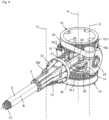
- a surgical instrument 1 with a hollow shaft 2which has an actuating unit 4 arranged at the proximal end 3 of the shaft 2, shown only schematically, and a tool tip 6 arranged at the distal end 5 of the shaft 2.
- the tool tip 6is connected to an instrument 7, which can be actuated via an actuating element 8 mounted axially displaceably in the shaft 2, which is operatively connected to the actuating unit 4 on the proximal side.
- the actuating unit 4can be a manually actuated handle or a structural unit designed for robotic use, i.e. can also be actuated without manual intervention.
- the actuating element 8which is mounted axially displaceably in the shaft 2 for actuating the instrument 7, which consists for example of two jaw parts, is designed as a pull/push rod in the embodiments shown.
- the steering gear 13 for the steering wires 12is designed as a motorized drive 13 in the medical instrument 1 shown in the figures and described below.
- the swash plateis mounted in a steering ring so that it can rotate about the longitudinal axis B of the shaft.
- a bearing ringis provided in the steering ring, which is coupled in a rotationally fixed manner to the third gear. This serves to ensure that the tool tip can be rotated about the longitudinal axis of the shaft in addition to pivoting relative to the longitudinal axis of the shaft, without the steering wires becoming twisted.
- the core of the drive 13is a spatially adjustable disk or swash plate 14 ( Fig. 3 , 9 , 10 ), on which the steering wires 12 are mounted in such a way that a displacement of the swash plate 14 via the steering wires 12 mounted on the swash plate 14 causes a pivoting of the tool tip 6.
- the swash plate 14can be displaced by means of the motorized drive or steering gear 13.
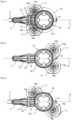
- the steering gear 13has, as in Fig. 2 to 9 can be seen, two drives with motors 17, 17' (in Fig. 9 not shown) with parallel drive axes C, C', which further run parallel to a common axis of rotation A of the two drive wheels 18, 19, between which the spatially adjustable swash plate 14 is arranged.
- Fig. 2 and 3show an example of a first embodiment of the steering gear 13 according to the invention for a surgical instrument 1, which as in Fig. 1 shown, is arranged at the proximal end 3 of the shaft 2, which defines the longitudinal or main axis B and has the bending mechanism 9 at the distal end 5.
- the drives of the steering gear 13have a first drive wheel 18 driven by the first motor 17 and a second drive wheel 19 driven by the second motor 17', between which the swash plate 14 is arranged.
- the two drive wheels 18, 19lie on a common axis of rotation A and are both designed as double wheels 18, 19, so that they each have a bevel gear ring 18.2, 19.2 and a drive ring 18.1, 19.1.
- the double wheels 18, 19can preferably be manufactured in one piece. Alternatively, however, it is also possible for each double wheel to consist of a bevel gear and a wheel with a drive ring connected to it.
- the bevel gear rims 18.2, 19.2 of the double wheels 18, 19face each other and mesh with a third gear 25 and a fourth gear 31 arranged opposite thereto, which are coupled to the swash plate 14 and lie on an axis of rotation D which is at a right angle to the common axis A of the double wheels 18, 19.
- the steering gear 13has a first pinion 16a, which is driven by the first motor 17 via a first drive shaft 15a and meshes with the drive ring 18.1 of the first double wheel 18.
- the second pinion 16bwhich meshes with the drive ring 19.1 of the second double wheel 19, is driven by the second motor 17' via a second drive shaft 15b.
- the drive shafts 15a and 15bdefine the first and second drive axes C and C', which run not only parallel to one another, but also parallel to the common axis of rotation A of the two drive wheels 18, 19.
- the positioning of the drive axles C, C' on a circular path U C around the drive wheels 18, 19can be selected almost arbitrarily, as in Fig. 4-6 is indicated, provided that the installation space there is not occupied by other instrument components such as main shaft 21, steering wires 12, fan washer 22 or actuating element 8.
- the Fig. 4-6The variants shown show arrangements of the drive units consisting of pinions 16a, 16b, drive shafts 15a, 15b and motors 17, 17' as close as possible to the longitudinal axis B, which is preferred for reasons of saving installation space.
- an arrangement of the drive units at any point on the circular path U Cis also conceivable, as long as the pinions 16a, 16b mesh with the drive rings 18.1, 19.1.
- the belt 44is designed as a toothed belt. Consequently, the pinion 16a, which is designed as a pulley, also has teeth.
- the second drive unitie, pinion 16b, belt 45 and drive ring 19.1, even if this is not apparent in the figure.
- belt drives other than a toothed belt drivecan also be used, e.g. flat belts, round belts, V-belts or V-ribbed belts, whereby the pulleys are designed with a circumferential profile corresponding to the drive belt.
- a toothed belt drivecan also be used, e.g. flat belts, round belts, V-belts or V-ribbed belts, whereby the pulleys are designed with a circumferential profile corresponding to the drive belt.
- Fig. 9In the example shown with belt transmission, an embodiment with a chain transmission is also conceivable (not shown figuratively), in which instead of the Fig.
- the steering wires 12 emerging from the shaft 2 at the proximal end 3 of the shaft 2, for which a shaft end piece 3 can be provided at the proximal shaft end, in which through-slots for the steering wires 12 are provided,are fanned out in the example shown via a fan disk 22 arranged on the shaft end piece 3 in a rotationally fixed manner with respect to the main shaft 21, whereby the radial distance of the steering wires 12 from the longitudinal axis B of the shaft 2 is increased.
- the diameter of the bundle of steering wires 12 coaxially surrounding the longitudinal axis B of the shaft 2 within the shaft 2 or at the distal end 5 in the area of the bending mechanism 9is, for example, 4 mm
- the diameter of the bundle formed by the steering wires 12 behind the fan disk 22is, for example, 18 mm.
- the adjustment angle of the swash plate 14is reduced by 4.5 times compared to the pivoting angle of the tool tip 6 that can be achieved at the distal end. In order to angle this by 90°, the swash plate 14 only needs to be pivoted by 20°.
- the drive wheels 18 and 19are coupled to a third gear 25, which is preferably designed as a bevel gear and is in engagement with the two bevel gear rings 18.2, 19.2 of the double wheels 18 and 19, so that the axis of rotation D of the third gear 25 intersects the common axis of rotation A of the drive wheels 18 and 19 and the longitudinal axis B of the shaft 2.
- a third gear 25which is preferably designed as a bevel gear and is in engagement with the two bevel gear rings 18.2, 19.2 of the double wheels 18 and 19, so that the axis of rotation D of the third gear 25 intersects the common axis of rotation A of the drive wheels 18 and 19 and the longitudinal axis B of the shaft 2.
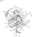
- the swash plate 14is pivotably mounted on a universal joint disk 28 via two bearing pins 27 arranged 180° apart, which in turn is pivotably mounted on the main shaft 21 via two bearing pins 29 arranged 180° apart.
- Fig. 10Due to the partial sectional view, only one bearing pin 27 and one bearing pin 29 can be seen.
- the swash plate 14is mounted via a bearing ring 32 in the steering ring 30, which is coupled in a rotationally fixed manner to the third gear 25, in order to enable rotation of the swash plate 14 about the longitudinal axis B of the shaft 2.
- the steering ring 30, which is coupled in a rotationally fixed manner to the third gear 25,is freely rotatable in relation to the fourth gear 31 by means of a bearing by means of a bearing ring 42, so that rotation of the fourth gear 31 about its axis of rotation D does not cause any rotation of the steering ring 30 and the swash plate 14.
- the described cardanic mounting of the swash plate 14 on the main shaft 21enables the swash plate 14 to be displaced three-dimensionally relative to the longitudinal axis B of the shaft 2. If, starting from the Fig. 10 In the neutral starting position shown, in which the swash plate 14 is aligned perpendicular to the longitudinal axis B of the shaft 2, the drive wheels 18 and 19 are driven via the motors 17, 17' (cf. Fig.
- This tilting of the swash plate 14 about the axis of rotation A relative to the longitudinal axis B of the shaft 2causes, via the steering wires 12, that the tool tip 6 is pivoted on the distal side in a corresponding manner relative to the longitudinal axis B of the shaft 2.
- This rotation of the swash plate 14 about the axis of rotation D relative to the longitudinal axis B of the shaft 2causes the tool tip 6 to be pivoted on the distal side in a corresponding manner relative to the longitudinal axis B of the shaft 2 via the steering wires 12.
- the swash plate 14is tilted about the common axis of rotation A of the drive wheels 18, 19 and at the same time is also rotated about the axis of rotation D of the third gear 25.
- the swash plate 14can be adjusted three-dimensionally relative to the longitudinal axis B of the shaft 2, which results in a corresponding spatial displacement of the tool tip 6 due to the coupling via the steering wires 12.
- a surgical instrument 1 designed as described aboveis characterized in that many thin steering wires 12 can be used to control the pivotable tool tip 6, and this control is carried out sensitively, precisely and reproducibly due to the motorized drive 13 for the swash plate 14 on which the steering wires 12 are mounted.
- the present inventionprovides a steering gear 13 for a surgical instrument 1, which is mounted on the proximal end 3 of a Shaft 2 can be arranged, which defines a longitudinal axis B and has an angular deflection mechanism 9 at the distal end 5, wherein the steering gear 13 has two motorized drives and is designed to spatially align a swash plate 14 via the setting angles of the two drives.
- the two driveseach have a drive wheel 18, 18', 19, 19' driven by motors 17, 17', which is designed as a double wheel 18, 18', 19, 19' with a bevel gear ring 18.2, 19.2 and a drive ring 18.1, 19.1.
- the swash plate 14is arranged between the two drive wheels 18, 19; 18', 19', which have a common axis of rotation A, and the bevel gear rings 18.2, 19.2 face each other, with the drive rings 18.1, 19.1 of both double wheels 18, 19; 18', 19' each being operatively connected to a pinion 16a, 16b.
- the pinions 16a, 16bwhich are each operatively connected to one of the drive rings 18.1, 19.1, can be driven by the respective motor 17, 17' via a drive shaft 15a, 15b, which defines a drive axis C, C', with the two drive axes C, C' running parallel to each other and parallel to the common axis of rotation A of the two drive wheels 18, 19; 18', 19'. Furthermore, a surgical instrument 1 is disclosed which has such a steering gear 13.
Landscapes
- Health & Medical Sciences (AREA)
- Engineering & Computer Science (AREA)
- Surgery (AREA)
- Life Sciences & Earth Sciences (AREA)
- Robotics (AREA)
- Heart & Thoracic Surgery (AREA)
- Nuclear Medicine, Radiotherapy & Molecular Imaging (AREA)
- Biomedical Technology (AREA)
- Medical Informatics (AREA)
- Molecular Biology (AREA)
- Animal Behavior & Ethology (AREA)
- General Health & Medical Sciences (AREA)
- Public Health (AREA)
- Veterinary Medicine (AREA)
- Mechanical Engineering (AREA)
- Ophthalmology & Optometry (AREA)
- Transmission Devices (AREA)
- Surgical Instruments (AREA)
Description
Translated fromGermanDie Erfindung betrifft ein chirurgisches Instrument und ein Lenkgetriebe dafür.The invention relates to a surgical instrument and a steering gear therefor.
Aus dem Stand der Technik sind chirurgische Instrumente bekannt, die manuell oder von einem Roboter geführt werden können und die Werkzeuge aufweisen, deren Werkzeugspitze mittels mehrerer ineinandergreifender Schwenkglieder verschwenkt werden kann. Diese Schwenkglieder sind mit einer Vielzahl Lenkdrähte oder -seile verbunden, um eine feinfühlige Steuerung der Werkzeugspitze zu erreichen. Mit vielen dünnen Lenkdrähten gegenüber wenigen dickeren Lenkdrähten kann eine gleichmäßigere Kraftverteilung in alle Abwinkelungsrichtungen erzielt werden.Surgical instruments are known from the state of the art that can be guided manually or by a robot and that have tools whose tool tips can be swiveled using several interlocking swivel members. These swivel members are connected to a large number of steering wires or cables in order to achieve sensitive control of the tool tip. With many thin steering wires compared to a few thicker steering wires, a more even distribution of force in all bending directions can be achieved.
Ein gattungsgemäßes chirurgisches Instrument ist bspw. aus der
Die Ausbildung des Antriebs für die Lenkdrähte mit der räumlich verstellbaren Taumelscheibe, an der alle vier Lenkdrähte gelagert sind, hat den Vorteil, dass dies eine räumlich kompakte Bauweise ermöglicht und nur ein Bauteil bewegt werden muss, um alle Lenkdrähte ansprechen zu können.The design of the drive for the steering wires with the spatially adjustable swash plate, on which all four steering wires are mounted, has the advantage that this enables a spatially compact design and only one component has to be moved in order to be able to address all steering wires.
Nachteilig an dieser bekannten Konstruktion ist die Verwendung einer nur geringen Anzahl von Lenkdrähten, nämlich von nur vier Lenkdrähten, und ferner die ausschließlich manuelle Betätigbarkeit der als Antrieb für die Lenkdrähte dienenden räumlich verstellbaren Scheibe, wodurch eine feinfühlige und reproduzierbare Verstellung der distalseitigen Schwenkglieder kaum möglich ist.A disadvantage of this known construction is the use of only a small number of steering wires, namely only four steering wires, and furthermore the exclusively manual operation of the spatially adjustable disk serving as a drive for the steering wires, which makes a sensitive and reproducible adjustment of the distal swivel members hardly possible.
In der
Die
Die vorstehende Gestaltung ist verbunden mit einem komplexen Aufbau und einer indirekten und spielbehafteten Ansteuerung, weil die Antriebe nicht in dem chirurgischen Instrument direkt angeordnet sind. Das daraus resultierende nicht lineare Übertragungsverhalten der Antriebsbewegung auf die Taumelscheibe kann zudem nur schlecht in einer Software-Steuerung abgebildet werden.The above design is associated with a complex structure and an indirect control system with play because the drives are not arranged directly in the surgical instrument. The resulting non-linear transmission behavior of the drive movement to the swash plate can also only be poorly represented in a software control system.
Auch
Die
Ausgehend von diesem Stand der Technik ist es Aufgabe der vorliegenden Erfindung, ein verbessertes Lenkgetriebe für ein chirurgisches Instrument bereitzustellen, das einen Antrieb der räumlich verstellbaren Taumelscheibe mit linearem Übertragungsverhalten hat. Diese Aufgabe wird durch ein Lenkgetriebe mit den Merkmalen des Anspruchs 1 gelöst. Die weitere Aufgabe ein chirurgisches Instrument bereitzustellen, dessen räumlich verstellbare Taumelscheibe durch ein konstruktiv einfaches und platzsparendes Lenkgetriebe angetrieben wird, wird durch das chirurgische Instrument mit den Merkmalen des abhängigen Anspruchs 8 gelöst.Based on this prior art, the object of the present invention is to provide an improved steering gear for a surgical instrument, which has a drive for the spatially adjustable swash plate with linear transmission behavior. This object is achieved by a steering gear with the features of claim 1. The further object of providing a surgical instrument, the spatially adjustable swash plate of which is driven by a structurally simple and space-saving steering gear, is achieved by the surgical instrument with the features of the
Weiterbildungen und bevorzugte Ausführungsformen des Lenkgetriebes und des chirurgischen Instruments sind in den Unteransprüchen ausgeführt.Further developments and preferred embodiments of the steering gear and the surgical instrument are set out in the subclaims.
Gemäß einer ersten Ausführungsform des erfindungsgemäßen Lenkgetriebes für ein chirurgisches Instrument, wobei das Lenkgetriebe am proximalen Ende eines hohlen Schafts anordenbar ist, der eine Längsachse B des Instruments definiert und am distalen Ende eine Abwinkelungsmechanik des chirurgischen Instruments aufweist, verfügt dieses über zwei motorisierte Antriebe und ist dazu ausgebildet, über die Stellwinkel der zwei Antriebe eine Taumelscheibe räumlich auszurichten. Diese wiederum ist dazu ausgebildet, die distale Abwinkelungsmechanik des chirurgischen Instruments zu steuern.According to a first embodiment of the steering gear according to the invention for a surgical instrument, wherein the steering gear can be arranged at the proximal end of a hollow shaft which defines a longitudinal axis B of the instrument and has a bending mechanism of the surgical instrument at the distal end, said steering gear has two motorized drives and is designed to spatially align a swash plate via the setting angles of the two drives. This in turn is designed to control the distal bending mechanism of the surgical instrument.
Erfindungsgemäß weist der erste Antrieb ein von einem ersten Motor angetriebenes erstes Antriebsrad auf, das als Doppelrad mit einem ersten Kegelradkranz und einem ersten Antriebskranz ausgebildet ist. Auch der zweite Antrieb weist ein von einem zweiten Motor angetriebenes zweites Antriebsrad auf, das als Doppelrad mit einem zweiten Kegelradkranz und einem zweiten Antriebskranz ausgebildet ist. Die Taumelscheibe ist zwischen den zwei Antriebsrädern, die eine gemeinsame Drehachse A aufweisen, angeordnet, wobei die Kegelradkränze einander zugewandt sind. Die Antriebskränze beider Doppelräder stehen mit jeweils einem Ritzel in Wirkverbindung, wobei ein erstes Ritzel, das mit dem ersten Antriebskranz in Wirkverbindung steht, über eine erste Antriebswelle, die eine erste Antriebsachse C definiert, durch den ersten Motor antreibbar ist. Ein zweites Ritzel, das mit dem zweiten Antriebskranz in Wirkverbindung steht, ist über eine zweite Antriebswelle, die eine zweite Antriebsachse C' definiert, durch den zweiten Motor antreibbar. Dabei verlaufen die zwei Antriebsachsen C, C' parallel zueinander und parallel zu der gemeinsamen Drehachse A der zwei Antriebsräder, sodass die Antriebsachsen bauraumsparend nahe an der Längsachse B des Instruments positioniert werden können.According to the invention, the first drive has a first drive wheel driven by a first motor, which is designed as a double wheel with a first bevel gear ring and a first drive ring. The second drive also has a second drive wheel driven by a second motor, which is designed as a double wheel with a second bevel gear ring and a second drive ring. The swash plate is between the two drive wheels, which have a common axis of rotation A, with the bevel gear rings facing each other. The drive rings of both double wheels are each operatively connected to a pinion, with a first pinion, which is operatively connected to the first drive ring, being drivable by the first motor via a first drive shaft, which defines a first drive axis C. A second pinion, which is operatively connected to the second drive ring, being drivable by the second motor via a second drive shaft, which defines a second drive axis C'. The two drive axes C, C' run parallel to each other and parallel to the common axis of rotation A of the two drive wheels, so that the drive axes can be positioned close to the longitudinal axis B of the instrument in a space-saving manner.
Durch den motorisierten Antrieb der räumlich verstellbaren Scheibe über das Lenkgetriebe, das mit den angetriebenen Doppelräder ein lineares Übertragungsverhalten aufweist, ist es möglich, die distalseitige Werkzeugspitze exakt, feinfühlig in kleinsten Schritten und auch reproduzierbar zu aktivieren. Die Doppelräder können dabei wahlweise einstückig gefertigt sein, aber es ist auch möglich, dass die Doppelräder jeweils aus einem Kegelrad und einem Antriebsrad, die miteinander verbunden sind, bestehen. Aus der Kombination von Antriebsradkranz und Kegelradkranz wird eine direkte Übertragung der durch die Antriebe initiierten Bewegungen auf die Taumelscheibe erreicht.The motorized drive of the spatially adjustable disk via the steering gear, which has a linear transmission behavior with the driven double wheels, makes it possible to activate the distal tool tip precisely, sensitively in the smallest steps and also reproducibly. The double wheels can optionally be manufactured as a single piece, but it is also possible for the double wheels to consist of a bevel gear and a drive gear that are connected to each other. The combination of the drive gear ring and the bevel gear ring achieves a direct transmission of the movements initiated by the drives to the swash plate.
In einer Ausführungsform des erfindungsgemäßen Lenkgetriebes können die zwei Doppelräder derart in Bezug auf die Taumelscheibe angeordnet sein, dass die zwei Antriebsachsen C, C' und die gemeinsame Drehachse A der zwei Doppelräder senkrecht, d. h. im rechten Winkel zu der Längsachse B des chirurgischen Instruments, verlaufen. Platzsparend können hierbei beide Motoren nebeneinander auf einer Seite in Bezug auf die Längsachse B senkrecht dazu angeordnet werden, sodass die Bauhöhe reduziert werden kann. Je nach vorhandenem Bauraum ist aber auch eine Anordnung der beiden Motoren diametral versetzt zueinander in Bezug auf die Längsachse B denkbar.In one embodiment of the steering gear according to the invention, the two double wheels can be arranged in relation to the swash plate in such a way that the two drive axes C, C' and the common axis of rotation A of the two double wheels run vertically, i.e. at right angles to the longitudinal axis B of the surgical instrument. To save space, both motors can be arranged next to each other on one side in relation to the longitudinal axis B, perpendicular to it, so that the overall height can be reduced. Depending on the available installation space, however, an arrangement of the two motors diametrically offset from each other in relation to the longitudinal axis B is also conceivable.
In einer dazu alternativen Ausführungsform des erfindungsgemäßen Lenkgetriebes können die beiden Antriebsräder als Hohl-Doppelräder ausgebildet sein und derart in Bezug auf die Taumelscheibe angeordnet werden, dass die gemeinsame Drehachse A der zwei Hohl-Doppelräder mit der Längsachse B des chirurgischen Instruments fluchtet bzw. zusammenfällt, und die zwei Antriebsachsen C, C' parallel zu der Längsachse B des chirurgischen Instruments verlaufen. Auch hierdurch ist eine bauraumsparende Anordnung der Motoren in der Nähe der Längsachse - und zwar parallel dazu - ermöglicht.In an alternative embodiment of the steering gear according to the invention, the two drive wheels can be designed as hollow double wheels and arranged in relation to the swash plate in such a way that the common axis of rotation A of the two hollow double wheels is aligned or coincides with the longitudinal axis B of the surgical instrument, and the two drive axes C, C' are parallel to the longitudinal axis B of the surgical instrument This also enables the motors to be arranged close to the longitudinal axis - and in fact parallel to it - in a space-saving manner.
In beiden Anordnungsvarianten des Lenkgetriebes können die Antriebskränze der Doppelräder bzw. Hohl-Doppelräder Zahnkränze und die Ritzel entsprechend Zahnräder sein, die mit den als Zahnkränzen ausgebildeten Antriebskränzen direkt in Eingriff stehen bzw. kämmen.In both arrangement variants of the steering gear, the drive rings of the double wheels or hollow double wheels can be gear rings and the pinions can be gears that directly engage or mesh with the drive rings designed as gear rings.
Als Alternative zu der Wirkverbindung aus Zahnkranz und Zahnrad sieht eine weitere Ausführungsform vor, dass die Antriebskränze der Doppelräder bzw. Hohl-Doppelräder und die Ritzel jeweils als Riemenscheiben mit einem Umfangsprofil für einen Antriebsriemen ausgebildet sind, wobei ein erster Antriebsriemen die Wirkverbindung des ersten Antriebskranzes mit dem ersten Ritzel bereitstellt und ein zweiter Antriebsriemen die Wirkverbindung des zweiten Antriebskranzes mit dem zweiten Ritzel ermöglicht.As an alternative to the operative connection of gear ring and gear wheel, a further embodiment provides that the drive rings of the double wheels or hollow double wheels and the pinions are each designed as pulleys with a circumferential profile for a drive belt, wherein a first drive belt provides the operative connection of the first drive ring with the first pinion and a second drive belt enables the operative connection of the second drive ring with the second pinion.
Als Antriebsriemen können Flach-, Rund-, Keil-, Keilrippen- oder Zahnriemen gewählt werden, wobei das Umfangsprofil der als Riemenscheiben ausgebildeten Antriebskränze und der Ritzel entsprechend ein Flach-, Rund-, Keil-, Keilrippen- oder Zahnprofil ist. Zahnriemen können bevorzugt sein, da durch den Formschluss zwischen Zahnriemen und Zahnprofil an den Riemenscheiben nicht nur hohe Kräfte bei geringerer Vorspannung übertragen werden können, sondern vor allem Schlupf verhindert wird und damit eine exakte Steuerung gewährleistet ist.Flat, round, V-belts, V-ribbed or toothed belts can be selected as drive belts, whereby the circumferential profile of the drive rings designed as pulleys and the pinions is a flat, round, V-belt, V-ribbed or toothed profile. Toothed belts may be preferred because the positive connection between the toothed belt and the tooth profile on the pulleys not only allows high forces to be transmitted with less pre-tension, but above all slippage is prevented and precise control is thus ensured.
Bei einem zum Riemenantrieb alternativen Kettenantrieb sind die Antriebskränze der Doppelräder bzw. Hohl-Doppelräder und die Ritzel entsprechend als Kettenräder für eine Antriebskette ausgebildet, wobei eine erste Antriebskette die Wirkverbindung des ersten Antriebskranzes mit dem ersten Ritzel und eine zweite Antriebskette die Wirkverbindung des zweiten Antriebskranzes mit dem zweiten Ritzel bereitstellen. Ein Riemenantrieb kann gegenüber einem Kettenantrieb wegen geringerer Kosten und größerer Laufruhe bevorzugt sein.In a chain drive as an alternative to the belt drive, the drive rings of the double wheels or hollow double wheels and the pinions are designed accordingly as chain wheels for a drive chain, with a first drive chain providing the operative connection of the first drive ring with the first pinion and a second drive chain providing the operative connection of the second drive ring with the second pinion. A belt drive can be preferred over a chain drive due to lower costs and greater smoothness.
Ferner kann für das Lenkgetriebe in einer weiteren erfindungsgemäßen Ausführungsform zur Ansteuerung der Taumelscheibe vorgesehen sein, dass die Taumelscheibe mit einem dritten Zahnrad gekoppelt ist, das mit den beiden Kegelradkränzen der beiden Doppelräder bzw. Hohl-Doppelräder in Eingriff steht und dessen Drehachse D in einem rechten Winkel zu der gemeinsamen Achse A der Doppelräder steht. Auf diese Weise können die Stellbewegungen der Antriebe über die (Hohl-) Doppelräder auf das dritte Zahnrad und von diesem auf die Taumelscheibe übertragen werden, die dadurch um die beiden Drehachsen A und D verkippt bzw. verschwenkt werden kann. Vorzugsweise kann die Taumelscheibe ferner mit einem vierten Zahnrad gekoppelt sein, das mit den beiden Kegelradkränzen der beiden Doppelräder bzw. Hohl-Doppelräder gekoppelt und auf der abgewandten Seite von dem dritten Zahnrad auf dessen Drehachse D angeordnet ist.Furthermore, in a further embodiment according to the invention, the steering gear can be provided for controlling the swash plate by the swash plate being coupled to a third gear which is in engagement with the two bevel gear rings of the two double wheels or hollow double wheels and whose axis of rotation D is at a right angle to the common axis A of the double wheels. In this way, the actuating movements of the drives can be transmitted via the (hollow) double wheels to the third gear and from there to the swash plate, which can thereby be tilted or pivoted about the two axes of rotation A and D. Preferably, the swash plate can also be coupled to a fourth gear, which is coupled to the two bevel gear rings of the two double wheels or hollow double wheels and is arranged on the side facing away from the third gear on its axis of rotation D.
Die Erfindung bezieht sich ferner auf ein chirurgisches Instrument. Gemäß einer ersten Ausführungsform des chirurgischen Instruments weist es einen Schaft, eine am proximalen Ende des Schaftes angeordnete Betätigungseinheit und ein am distalen Ende des Schaftes angeordnetes Werkzeug auf. Das Werkzeug hat eine Werkzeugspitze, die mittels einer distalen Abwinkelungsmechanik abgewinkelt werden kann. Die Abwinkelungsmechanik kann durch eine mittels zweier Antriebe räumlich ausrichtbare Taumelscheibe gesteuert bzw. ausgerichtet werden, wozu das chirurgische Instrument ein erfindungsgemäßes Lenkgetriebe aufweist, wobei die beiden Antriebe Teil des erfindungsgemäßen Lenkgetriebes sind, das dazu ausgebildet ist, die Stellwinkel der zwei Antriebe auf die räumliche Ausrichtung der Taumelscheibe zu übertragen, um so die Abwinkelungsmechanik zu steuern.The invention further relates to a surgical instrument. According to a first embodiment of the surgical instrument, it has a shaft, an actuating unit arranged at the proximal end of the shaft and a tool arranged at the distal end of the shaft. The tool has a tool tip that can be angled by means of a distal bending mechanism. The bending mechanism can be controlled or aligned by a swash plate that can be spatially aligned by means of two drives, for which purpose the surgical instrument has a steering gear according to the invention, wherein the two drives are part of the steering gear according to the invention, which is designed to transfer the setting angles of the two drives to the spatial alignment of the swash plate in order to control the bending mechanism.
Durch das erfindungsgemäße Lenkgetriebe kann das chirurgische Instrument konstruktiv einfach und platzsparend aufgebaut werden, so dass eine einfache Verbindung zu einem Roboter-Arm ermöglicht werden kann, bei der die Bewegung der Antriebe linear auf die Werkzeugspitze übertragen werden kann. Folge ist eine exakt steuerbare Verwendung des chirurgischen Instruments.The steering gear according to the invention allows the surgical instrument to be constructed in a simple and space-saving manner, so that a simple connection to a robot arm is possible, in which the movement of the drives can be transferred linearly to the tool tip. The result is a precisely controllable use of the surgical instrument.
Um die räumlich verstellbare Taumelscheibe trotz der drehfesten Kopplung mit dem dritten Zahnrad, das mit den beiden Kegelradkränzen der beiden Doppelräder in Eingriff steht, dreidimensional verstellen zu können, d. h. die Kipp- bzw. Schwenkbewegungen mit einer Rotation der Taumelscheibe um die Längsachse B überlagern zu können, kann eine bevorzugte Ausführungsform des chirurgischen Instruments vorsehen, dass die Taumelscheibe um die Längsachse B des Schaftes über einen Lagerring rotierbar in einem Lenkring gelagert ist, der drehfest mit dem dritten Zahnrad gekoppelt ist. Zur rotativen Kopplung der Taumelscheibe mit einer koaxial zu einer Längsachse B des Schaftes verlaufenden Hauptwelle kann die Taumelscheibe kardanisch mit der Hauptwelle gekoppelt sein. Somit kann die Werkzeugspitze mittels der Taumelscheibe zusätzlich zum Verschwenken bzw. Verkippen durch die beiden Antriebe durch die Hauptwelle relativ zur Längsachse des Schaftes um die Längsachse des Schaftes rotiert werden.In order to be able to adjust the spatially adjustable swash plate three-dimensionally despite the rotationally fixed coupling with the third gear, which is in engagement with the two bevel gear rings of the two double wheels, i.e. to be able to superimpose the tilting or swiveling movements with a rotation of the swash plate about the longitudinal axis B, a preferred embodiment of the surgical instrument can provide that the swash plate is mounted so as to be rotatable about the longitudinal axis B of the shaft via a bearing ring in a steering ring which is rotationally fixedly coupled to the third gear. For the rotational coupling of the swash plate with a main shaft running coaxially to a longitudinal axis B of the shaft, the swash plate can be coupled to the main shaft in a cardanic manner. The tool tip can be rotated around the longitudinal axis of the shaft by means of the swash plate in addition to the pivoting or tilting by the two drives through the main shaft relative to the longitudinal axis of the shaft.
Zur Ausbildung der kardanischen Lagerung der räumlich verstellbaren Taumelscheibe kann eine Ausführungsform des erfindungsgemäßen chirurgischen Instruments vorsehend, dass die Taumelscheibe über zwei um 180 ° versetzt zueinander angeordnete Lagerstifte verschwenkbar auf einer Kreuzgelenkscheibe gelagert ist, wobei die Kreuzgelenkscheibe über zwei um 180 ° versetzt zueinander angeordnete Lagerstifte verschwenkbar auf der Hauptwelle gelagert ist, und wobei die Lagerstifte der Taumelscheibe und der Kreuzgelenkscheibe um 90 ° versetzt zueinander angeordnet sind. Die kardanische Aufhängung ermöglicht eine Bewegungsführung in allen drei Raumachsen, wodurch die Werkzeugspitze gezielt gesteuert werden kann. Alternativ zu einer Kreuzgelenkscheibe mit zwei rechtwinklig gekreuzten Stift-Paaren zur kardanischen Lagerung der Taumelscheibe auf der Hauptwelle kann eine vorteilhafte Ausführungsform vorsehen, dass zur kardanischen Lagerung die Hauptwelle zwei in ihrer Außenfläche vorliegende Führungsnuten aufweist, die sich diametral und längs der Hauptwelle erstrecken, wobei die Taumelscheibe, die kreisringförmig mit einer Außenseite und einer Innenseite ausgebildet ist, zwei diametral und radial nach innen weisend an der Taumelscheibe angeordnete Stifte aufweist. Jeder der zwei fest an bzw. in der Taumelscheibe montierten Stifte greift in eine der beidseitig in die Hauptwelle eingebrachten Führungsnuten ein, sodass ein Drehwinkel der Welle auf die Taumelscheibe übertragbar ist. Vorteilhaft ergibt sich so eine drehsteife Verbindung zwischen Hauptwelle und Taumelscheibe, die auch bei einem großen Winkelversatz (± 40 ° und mehr) und Axialversatz eine Drehwinkelübertragung erlaubt, und dabei sehr kompakt aufgebaut, sowie einfach herzustellen und zu montieren ist. Grundsätzlich können allerdings auch eine Bogenzahnkupplung trotz eines relativ geringen Winkelversatzes, ein Gleichlaufgelenk trotz der aufwändigen Fertigung und komplexen Montage oder eine stoffschlüssige Kupplung, die häufig mit einer spielbehafteten Drehwinkelübertragung verbunden ist, zur kardanischen Lagerung einer Taumelscheibe auf einer Hauptwelle eingesetzt werden.To form the cardanic mounting of the spatially adjustable swash plate, an embodiment of the surgical instrument according to the invention can provide that the swash plate is pivotably mounted on a universal joint disc via two bearing pins arranged 180° apart, wherein the universal joint disc is pivotably mounted on the main shaft via two bearing pins arranged 180° apart, and wherein the bearing pins of the swash plate and the universal joint disc are arranged 90° apart. The cardanic suspension enables movement to be guided in all three spatial axes, whereby the tool tip can be controlled in a targeted manner. As an alternative to a universal joint disk with two pairs of pins crossed at right angles for the cardanic mounting of the swash plate on the main shaft, an advantageous embodiment can provide that the main shaft has two guide grooves in its outer surface for the cardanic mounting, which extend diametrically and along the main shaft, whereby the swash plate, which is designed as a circular ring with an outer side and an inner side, has two pins arranged diametrically and radially inward on the swash plate. Each of the two pins firmly mounted on or in the swash plate engages in one of the guide grooves made on both sides of the main shaft, so that an angle of rotation of the shaft can be transferred to the swash plate. This advantageously results in a torsionally rigid connection between the main shaft and the swash plate, which allows a rotation angle to be transmitted even with a large angular offset (± 40 ° and more) and axial offset, and is very compact in design and easy to manufacture and assemble. In principle, however, a curved tooth coupling despite a relatively small angular offset, a constant velocity joint despite the complex manufacturing and assembly, or a material-fit coupling, which is often associated with a rotation angle transmission with play, can also be used for the cardanic mounting of a swash plate on a main shaft.
In einer weiteren Ausführungsform des erfindungsgemäßen chirurgischen Instruments verlaufen in Längsrichtung des Schaftes Lenkdrähte, die mit der Taumelscheibe des Lenkgetriebes verbunden sind. Vorzugsweise können die Lenkdrähte an der Taumelscheibe lösbar befestigt sein, beispielsweise mittels einer Klemmverbindung, damit in einem Fall der Beschädigung die Lenkdrähte einfach ausgetauscht werden können. Da die Taumelscheibe rotatorisch mit der Hauptwelle gekoppelt ist und durch den Lagerring drehbar in dem Lenkring gelagert ist, der drehfest mit dem dritten Zahnrad gekoppelt ist, wird bewirkt, dass weiter vorteilhaft beim Verschwenken der Werkzeugspitze relativ zur Längsachse und Rotieren um die Längsachse des Schaftes das Verdrillen der Lenkdrähte verhindert wird.In a further embodiment of the surgical instrument according to the invention, steering wires run in the longitudinal direction of the shaft and are connected to the swash plate of the steering gear. Preferably, the steering wires can be detachably attached to the swash plate. be attached, for example by means of a clamp connection, so that in the event of damage the steering wires can be easily replaced. Since the swash plate is rotationally coupled to the main shaft and is rotatably mounted by the bearing ring in the steering ring, which is rotationally fixedly coupled to the third gear, the twisting of the steering wires is prevented, which is further advantageous when the tool tip is pivoted relative to the longitudinal axis and rotated about the longitudinal axis of the shaft.
Ferner sieht eine noch weitere Ausführungsform des erfindungsgemäßen chirurgischen Instruments vor, dass das vierte Zahnrad mit der Taumelscheibe über einen Lagerring mit dem Lenkring gekoppelt ist, wobei das vierte Zahnrad gegenüber dem dritten Zahnrad frei drehbar ist. Dieses vierte Zahnrad schließt die umlaufende Verzahnungskette und sorgt so für eine gleichmäßig umlaufende und spielfreie Kraftverteilung.Furthermore, a further embodiment of the surgical instrument according to the invention provides that the fourth gearwheel is coupled to the swash plate via a bearing ring with the steering ring, wherein the fourth gearwheel can rotate freely relative to the third gearwheel. This fourth gearwheel closes the rotating toothed chain and thus ensures a uniform rotating and play-free force distribution.
In einer weiteren Ausführungsform des erfindungsgemäßen chirurgischen Instruments ist ein Betätigungselement axial verschiebbar in dem Schaft (und der Hauptwelle) gelagert und steht proximalseitig mit der Betätigungseinheit in Wirkverbindung. Die distale Abwinkelungsmechanik der abwinkelbaren Werkzeugspitze besteht aus an dem distalen Ende des Schaftes angeordneten Schwenkgliedern, die über die in Längsrichtung des Schaftes verlaufenden Lenkdrähte mit der Taumelscheibe verbunden sind.In a further embodiment of the surgical instrument according to the invention, an actuating element is mounted in the shaft (and the main shaft) so that it can move axially and is operatively connected to the actuating unit on the proximal side. The distal bending mechanism of the bendable tool tip consists of pivoting members arranged at the distal end of the shaft, which are connected to the swash plate via the steering wires running in the longitudinal direction of the shaft.
In einer weiteren Ausführungsform des erfindungsgemäßen chirurgischen Instruments ist ein radialer Abstand der Lenkdrähte von der Längsachse des Schaftes an der Taumelscheibe größer als am proximalen Ende des Schaftes, aus dem die Lenkdrähte austreten. Dabei können die Lenkdrähte sich von dem proximalen Ende des Schaftes direkt zu der Taumelscheibe erstrecken, wobei die Lenkdrähte unter einem von 90° abweichenden Winkel zur Taumelscheibe verlaufen. Alternativ kann distalseitig vor der Taumelscheibe eine Fächerscheibe auf der Hauptwelle angeordnet sein, die den radialen Abstand der aus dem proximalen Schaftende austretenden Lenkdrähte von der Längsachse des Schaftes vergrößert, sodass die Lenkdrähte zwischen der Fächerscheibe und der Taumelscheibe annährend parallel zueinander verlaufen und in Bezug auf eine Scheibenfläche der Taumelscheibe einen Winkel von ca. 90° bilden. Aufgrund des geringeren Bauraumbedarfs kann die Variante ohne Fächerscheibe bevorzugt sein. Durch die Vergrößerung des radialen Abstandes der Lenkdrähte von der Längsachse des Schaftes, von beispielsweise einem Durchmesser von 4 mm auf einen Durchmesser von 18 mm, werden nicht nur die Montage und Fertigung des mit der räumlich verstellbaren Scheibe ausgestatten Antriebs der Lenkdrähte vereinfacht, sondern auch die Verstellwinkel der räumlich verstellbaren Scheibe bzw. infolge des vergrößerten Hebels die zur Abwinkelung benötigten Kräfte verringert, um einen dem Maß der Durchmesservergrößerung entsprechenden Verschwenkwinkel der Werkzeugspitze zu erzielenIn a further embodiment of the surgical instrument according to the invention, a radial distance of the steering wires from the longitudinal axis of the shaft on the swash plate is greater than at the proximal end of the shaft from which the steering wires emerge. The steering wires can extend from the proximal end of the shaft directly to the swash plate, with the steering wires running at an angle to the swash plate that differs from 90°. Alternatively, a fan disk can be arranged on the main shaft on the distal side in front of the swash plate, which increases the radial distance of the steering wires emerging from the proximal shaft end from the longitudinal axis of the shaft, so that the steering wires run approximately parallel to one another between the fan disk and the swash plate and form an angle of approximately 90° with respect to a disk surface of the swash plate. Due to the smaller installation space requirement, the variant without a fan disk can be preferred. By increasing the radial distance of the steering wires from the longitudinal axis of the shaft, for example from a diameter of 4 mm to a diameter of 18 mm, not only the assembly and production of the equipped with the spatially adjustable disc, not only simplifies the drive of the steering wires, but also reduces the adjustment angle of the spatially adjustable disc or, as a result of the enlarged lever, the forces required for bending in order to achieve a swivel angle of the tool tip corresponding to the extent of the diameter increase
Um beim Verschwenken des dritten und vierten Zahnrads relativ zur Längsachse des Schaftes eine Kollision der Zahnräder mit den Lenkdrähten und gegebenenfalls dem Betätigungselement zu vermeiden, können in den Zahnkränzen des dritten Zahnrads und des vierten Zahnrads Aussparungen für die Lenkdrähte und das Betätigungselement ausgebildet sein.In order to avoid a collision of the gears with the steering wires and possibly the actuating element when pivoting the third and fourth gears relative to the longitudinal axis of the shaft, recesses for the steering wires and the actuating element can be formed in the gear rings of the third gear and the fourth gear.
Das erfindungsgemäße chirurgische Instrument hat den Vorteil, dass viele dünne Lenkdrähte zur Ansteuerung der verschwenkbaren Werkzeugspitze verwendet werden können und diese Ansteuerung aufgrund des motorisierten Antriebs für die räumlich verstellbare Scheibe, an der die Lenkdrähte proximalseitig gelagert sind, feinfühlig, exakt und reproduzierbar erfolgt.The surgical instrument according to the invention has the advantage that many thin steering wires can be used to control the pivotable tool tip and that this control is sensitive, precise and reproducible due to the motorized drive for the spatially adjustable disk on which the steering wires are mounted on the proximal side.
Weitere Ausführungsformen sowie einige der Vorteile, die mit diesen und weiteren Ausführungsformen verbunden sind, werden durch die nachfolgende ausführliche Beschreibung unter Bezug auf die begleitenden Figuren deutlich und besser verständlich. Gegenstände oder Teile derselben, die im Wesentlichen gleich oder ähnlich sind, können mit denselben Bezugszeichen versehen sein. Die Figuren sind lediglich eine schematische Darstellung einer Ausführungsform der Erfindung. In den Zeichnungen ist ein Ausführungsbeispiel der Erfindung dargestellt. Die Zeichnungen und die Beschreibung enthalten zahlreiche Merkmale in Kombination. Der Fachmann wird die Merkmale zweckmäßigerweise auch einzeln betrachten und zu sinnvollen weiteren Kombinationen unter Einhaltung des Geltungsbereichs der Ansprüche zusammenfassen.Further embodiments and some of the advantages associated with these and further embodiments will become clear and better understood from the following detailed description with reference to the accompanying figures. Objects or parts thereof that are substantially the same or similar may be provided with the same reference numerals. The figures are merely a schematic representation of an embodiment of the invention. An embodiment of the invention is shown in the drawings. The drawings and the description contain numerous features in combination. The person skilled in the art will expediently also consider the features individually and combine them into useful further combinations while adhering to the scope of the claims.
Dabei zeigen:
- Fig. 1
- eine schematische perspektivische Seitenansicht eines erfindungsgemäßen medizinischen Instruments,
- Fig. 2
- eine perspektivische Ansicht des Antriebs gemäß
Fig. 1 in einer ersten Ausführungsform, - Fig. 3
- eine Rückansicht auf den Antrieb gemäß
Fig. 2 , - Fig. 4
- eine Draufsicht auf den Antrieb gemäß
Fig. 2 , - Fig. 5
- eine Draufsicht auf eine Variante des Antriebs gemäß
Fig. 2 , - Fig. 6
- eine Draufsicht auf eine weitere Variante des Antriebs gemäß
Fig. 2 , - Fig. 7
- eine perspektivische Ansicht des Antriebs gemäß
Fig. 1 in einer zweiten Ausführungsform, - Fig. 8
- eine Draufsicht auf den Antrieb gemäß
Fig. 7 , - Fig. 9
- eine perspektivische Ansicht des Antriebs gemäß
Fig. 1 in einer dritten Ausführungsform, - Fig. 10
- eine perspektivische, teilweise geschnittene Detaildarstellung des Taumelscheibengetriebes.
- Fig. 1
- a schematic perspective side view of a medical instrument according to the invention,
- Fig. 2
- a perspective view of the drive according to
Fig. 1 in a first embodiment, - Fig. 3
- a rear view of the drive according to
Fig. 2 , - Fig. 4
- a top view of the drive according to
Fig. 2 , - Fig. 5
- a plan view of a variant of the drive according to
Fig. 2 , - Fig. 6
- a plan view of another variant of the drive according to
Fig. 2 , - Fig. 7
- a perspective view of the drive according to
Fig. 1 in a second embodiment, - Fig. 8
- a top view of the drive according to
Fig. 7 , - Fig. 9
- a perspective view of the drive according to
Fig. 1 in a third embodiment, - Fig. 10
- a perspective, partially sectioned detailed view of the swash plate gear.
In
Bei dem Instrument 7 der Werkzeugspitze 6 kann es sich beispielsweise um ein mit Maulteilen versehenes Werkzeug, wie in
Die Werkzeugspitze 6 ist über einen Gelenkmechanismus 9 relativ zur Längsachse 10 des Schaftes 2 verschwenkbar, wobei der Gelenkmechanismus 9 aus am distalen Ende des Schaftes 5 angeordneten Schwenkgliedern 11 besteht, die über in Längsrichtung B des Schaftes 2 verlaufende Lenkdrähte 12 so mit einem am proximalen Ende 3 des Schaftes 2 angeordneten Antrieb bzw. Lenkgetriebe 13 verbunden sind, dass eine Bewegung des proximalseitigen Lenkgetriebes 13 eine entsprechende relative Bewegung der distalseitigen Schwenkglieder 11 und somit ein Verschwenken der Werkzeugspitze 6 verursacht.The
Auch wenn voranstehend und nachfolgend nur der Begriff Lenkdrähte 12 verwendet wird, können funktional auch Lenkseile verwendet werden, weshalb der verwendete Begriff Lenkdrähte 12 synonym auch als Lenkseil zu lesen und zu verstehen ist.Even if only the
Das axialverschiebbar im Schaft 2 gelagerte Betätigungselement 8 zum Betätigen des beispielsweise aus zwei Maulteilen bestehenden Instruments 7 ist bei den dargestellten Ausführungsformen als Zug-/Schubstange ausgebildet.The
Das Lenkgetriebe 13 für die Lenkdrähte 12 ist bei dem in den Abbildungen dargestellten und nachfolgend beschriebenen medizinischen Instrument 1 als motorisierter Antrieb 13 ausgebildet.The
In noch einer weiteren Ausführungsform des erfindungsgemäßen chirurgischen Instruments ist die Taumelscheibe um die Längsachse B des Schaftes rotierbar in einem Lenkring gelagert. Dazu ist ein Lagerring in dem Lenkring vorgesehen, der drehfest mit dem dritten Zahnrad gekoppelt ist. Dies dient dazu, dass die Werkzeugspitze zusätzlich zum Verschwenken relativ zur Längsachse des Schaftes auch um die Längsachse des Schaftes rotiert werden kann, ohne dass die Lenkdrähte verdrillt werden.In yet another embodiment of the surgical instrument according to the invention, the swash plate is mounted in a steering ring so that it can rotate about the longitudinal axis B of the shaft. For this purpose, a bearing ring is provided in the steering ring, which is coupled in a rotationally fixed manner to the third gear. This serves to ensure that the tool tip can be rotated about the longitudinal axis of the shaft in addition to pivoting relative to the longitudinal axis of the shaft, without the steering wires becoming twisted.
Kernstück des Antriebs 13 ist eine räumlich verstellbare Scheibe bzw. Taumelscheibe 14 (
Durch die Verwendung eines motorisierten Antriebs 13 für die Taumelscheibe 14 ist es möglich, die Lenkdrähte 12 zum Verschwenken der distalseitigen Schwenkglieder 11 bzw. der Werkzeugspitze 6 exakt, feinfühlig in kleinsten Schritten und auch reproduzierbar anzusteuern. Darüber hinaus ist die Anzahl der zu verwendenden Lenkdrähte 12 für einen motorisierten Antrieb 13 recht frei wählbar.By using a
Das Lenkgetriebe 13 weist, wie in
Die Kegelradkränze 18.2, 19.2 der Doppelräder 18, 19 sind einander zugewandt und kämmen mit einem dritten Zahnrad 25 und einem diesem gegenüber liegend angeordneten vierten Zahnrad 31, die mit der Taumelscheibe 14 gekoppelt sind und auf einer Drehachse D liegen, die in einem rechten Winkel zu der gemeinsamen Achse A der Doppelräder 18, 19 steht.The bevel gear rims 18.2, 19.2 of the
Um die Stellbewegungen der Motoren 17, 17' auf die Antriebsräder 18, 19 zu übertragen, weist das Lenkgetriebe 13 ein erstes Ritzel 16a auf, das über eine erste Antriebswelle 15a von dem ersten Motor 17 angetrieben wird, und mit dem Antriebskranz 18.1 des ersten Doppelrads 18 kämmt. Entsprechend wird das zweite Ritzel 16b, das mit dem Antriebskranz 19.1 des zweiten Doppelrads 19 kämmt, über eine zweite Antriebswelle 15b von dem zweiten Motor 17' angetrieben. Die Antriebswellen 15a und 15b definieren die erste und zweite Antriebsachse C und C', die nicht nur parallel zueinander, sondern auch parallel zu der gemeinsamen Drehachse A der zwei Antriebsräder 18, 19 verlaufen.In order to transmit the actuating movements of the
Mit dieser Anordnung können die zwei angetriebenen Doppelräder 18, 19 des Lenkgetriebes 13 derart in Bezug auf die Taumelscheibe 14 angeordnet werden, dass die zwei Antriebsachsen C, C' und die gemeinsame Drehachse A der zwei Doppelräder 18, 19 senkrecht, d. h. im rechten Winkel zu der Längsachse B des chirurgischen Instruments 1 verlaufen. Auf diese Weise können die Antriebsachsen C, C' relativ nahe an Längsachse B positioniert werden. Da durch das Lenkgetriebe 13 die Motoren 17, 17' nicht gegenüber liegend verbaut werden müssen, um die beiden Antriebsräder 18, 19 zu bewegen, kann die Bauhöhe des Instruments durch die parallele Anordnung beider Motoren 17, 17' nebeneinander auf einer Seite in Bezug zu der Längsachse B reduziert werden.With this arrangement, the two driven
Die Positionierung der Antriebsachsen C, C' auf einer Kreisbahn UC um die Antriebsräder 18, 19 ist dabei nahezu beliebig wählbar, wie in
In
In den mit
In
Wie in
Selbstverständlich sind auch von einem Zahnriemengetriebe abweichende Riemengetriebe, z. B. Flachriemen, Rundriemen, Keilriemen oder Keilrippenriemen, einsetzbar, wobei die Riemenscheiben mit einem dem Antriebsriemen entsprechenden Umfangsprofil ausgebildet sind. Analog zu dem in
Bei den Ausführungen mit Antriebsriemen oder entsprechend Antriebskette ergibt sich, dass die Positionierung der Ritzel 16a, 16b bzw. der Antriebsachsen C, C' nicht nur unabhängig voneinander und beliebig auf einer Kreisbahn um die Antriebsräder 18, 19, sondern durch Variation der Länge des Antriebsriemens bzw. der Kette auch in beliebigem Abstand von den Antriebsrädern 18, 19 gewählt werden kann. Da jedoch eine Bauraumreduktion erstrebenswert ist, ist eine Positionierung der Antriebsachsen C, C' nahe der Antriebsräder 18, 19, und vorzugsweise auch nahe der Längsachse B bevorzugt.Of course, belt drives other than a toothed belt drive can also be used, e.g. flat belts, round belts, V-belts or V-ribbed belts, whereby the pulleys are designed with a circumferential profile corresponding to the drive belt. Analogous to the
In the case of designs with drive belts or corresponding drive chains, the positioning of the
Der nachfolgend beschriebene Aufbau der räumlich verstellbaren Scheibe 14 und deren Lagerung sind bei allen Ausführungsformen des motorisierten Antriebs bzw. Lenkgetriebes 13 identisch. Der Aufbau und der Betrieb des Lenkgetriebes 13 sowie insbesondere der über die Antriebseinheiten betätigbaren Taumelscheibe 14 werden nachfolgend anhand
Wie aus den Abbildungen ersichtlich, ist im Schaft 2 eine sich koaxial zur Längsachse B des Schaftes 2 erstreckende hohle Hauptwelle 21 angeordnet, die um die Längsachse B des Schaftes 2 rotierbar ist und sich über das proximale Ende 3 des Schaftes 2 hinaus bis in den Bereich des Lenkgetriebes 13 erstreckt. Innerhalb dieser hohlen Hauptwelle 21 ist axialverschiebbar das Betätigungselement 8 zur Betätigung des Instruments 7 gelagert.As can be seen from the figures, a hollow
Die am proximalen Ende 3 des Schaftes 2 aus dem Schaft 2 austretenden Lenkdrähte 12, wofür am proximalen Schaftende ein Schaftendstück 3 vorgesehen sein kann, in dem Durchtrittschlitze für die Lenkdrähte 12 vorgesehen sind, werden im dargestellten Beispiel über eine drehfest in Bezug auf der Hauptwelle 21 an dem Schaftendstück 3 angeordnete Fächerscheibe 22 aufgefächert, wodurch der radiale Abstand der Lenkdrähte 12 von der Längsachse B des Schaftes 2 vergrößert wird. Während der Durchmesser des die Längsachse B des Schaftes 2 koaxial umgebenden Bündels der Lenkdrähte 12 innerhalb des Schaftes 2 bzw. an dem distalen Ende 5 im Bereich der Abwinkelungsmechanik 9 beispielsweise 4 mm beträgt, beträgt der Durchmesser des von den Lenkdrähten 12 gebildeten Bündels hinter der Fächerscheibe 22 beispielsweise 18 mm. Durch die mit Hilfe der Fächerscheibe 22 erzielte Vergrößerung des radialen Abstandes der Lenkdrähte 12 von der Längsachse B des Schaftes 2 werden nicht nur die Montage und Fertigung des mit der Taumelscheibe 14 ausgestatten Getriebes 13 vereinfacht, sondern wird auch der notwendige Verstellwinkel der Taumelscheibe 14 proportional verringert, um einen erwünscht hohen Verschwenkwinkel der Werkzeugspitze 6 zu erzielen. Mit dieser beispielhaften Vergrößerung des Durchmessers des Lenkdrahtbündels von 4 mm innerhalb des Schaftes 2 auf 18 mm hinter der Fächerscheibe 22 verringert sich ein Verstellwinkel der Taumelscheibe 14 entsprechend um das 4,5-fache gegenüber dem am distalen Ende erzielbaren Verschwenkwinkel der Werkzeugspitze 6. Um diese um 90° abzuwinkeln, bedarf es somit nur einer Verschwenkung der Taumelscheibe 14 um 20°.The
Proximalseitig hinter der Fächerscheibe 22 werden die parallel zur Längsachse B des Schaftes 2 verlaufenden Lenkdrähte 12 der Taumelscheibe 14 zugeführt. Zum Festlegen der Lenkdrähte 12 an der Taumelscheibe 14 sind in der Taumelscheibe 14 Durchgangsbohrungen 23 für jeden Lenkdraht 12 ausgebildet, wobei im dargestellten Beispiel die Lenkdrähte 12 innerhalb der Durchgangsbohrungen 23 über Madenschrauben 24 kraftschlüssig mit der Taumelscheibe 14 verbunden und fixiert sind. Dazu alternative Befestigungsformen der Lenkdrähte an der Taumelscheibe umfassen beispielsweise auch Schweißen oder Crimpen oder andere Klemmvorrichtungen.On the proximal side behind the
Die Antriebsräder 18 und 19 sind mit einem dritten Zahnrad 25 gekoppelt, das vorzugsweise als Kegelrad ausgebildet ist und mit den beiden Kegelradkränzen 18.2, 19.2 der Doppelräder 18 und 19 in Eingriff steht, sodass die Drehachse D des dritten Zahnrads 25 die gemeinsame Drehachse A der Antriebsräder 18 und 19 sowie die Längsachse B des Schaftes 2 schneidet. Durch die drei miteinander kämmenden Zahnräder 18, 19 und 25 wird jede Bewegung der beiden Antriebsräder 18 und 19 direkt auf die mit dem dritten Zahnrad 25 gekoppelte Taumelscheibe 14 übertragen, was eine direkte Betätigung der Lenkdrähte 12 bewirkt.The
Zur Ausbildung einer kardanischen Lagerung der Taumelscheibe 14 auf der Hauptwelle 21 ist die Taumelscheibe 14 über zwei um 180° versetzt zueinander angeordnete Lagerstifte 27 verschwenkbar auf einer Kreuzgelenkscheibe 28 gelagert, die wiederrum über zwei um 180° versetzt zueinander angeordnete Lagerstifte 29 verschwenkbar auf der Hauptwelle 21 gelagert ist. In
Die Lagerstifte 27 der Taumelscheibe 14 und die Lagerstifte 29 der Kreuzgelenkscheibe 28 sind dabei um 90° versetzt zueinander angeordnet. Diese Lagerung ermöglicht es, die Taumelscheibe 14 um zwei rechtwinklig zueinander stehende Achsen relativ zur Längsachse B des Schaftes 2 zu verschwenken und eine Rotation der Hauptwelle 21 um die Längsachse B auf die Taumelscheibe 14 zu übertragen, wodurch über die Lenkdrähte 12 distalseitig die Werkzeugspitze 6 in alle Raumrichtungen relativ zur Längsachse B des Schaftes 2 verschwenkbar ist.The bearing pins 27 of the
Eine nicht dargestellte, alternative kardanische Lagerung der Taumelscheibe 14 auf der Hauptwelle 21 sieht vor, dass die Hauptwelle 21 in dem zur Lagerung der Taumelscheibe 14 vorgesehenen Bereich zwei sich längs der Hauptwelle 21 erstreckende und beidseitig bzw. diametral in der Hauptwelle 21 eingebrachte Führungsnuten aufweist, in die zwei diametral und radial nach innen weisend an der Taumelscheibe 14 angeordnete Stifte eingreifen. Durch diesen Eingriff kann die Taumelscheibe 14 aus einer neutralen Position, in der die Taumelscheibe 14 in einer durch die Drehachse A definierten Ebene senkrecht, d. h. rechtwinklig, zur Längsachse B liegt, sowohl um Drehachse D als auch um Drehachse A verschwenkt werden. Überlagerte Bewegungen durch Verschwenken um beide Drehachsen A, D, sind ebenfalls möglich. Ferner gestattet der Eingriff der Stifte 29 in die Führungsnuten 20a die Übertragung eines Drehwinkels der Hauptwelle 21 auf die Taumelscheibe 14, sodass die Taumelscheibe 14 dreidimensional relativ zur Längsachse B des Schaftes 2 verlagert werden kann. Die maximale Verkippung bzw. Verdrehung bzw. die maximalen Kipp- und Drehwinkel um Drehachse A und D sind durch die Länge und Tiefe der Führungsnuten 20a im Zusammenwirken mit Innendurchmesser und Stärke der Taumelscheibe 14 und Länge der Stifte 29 bestimmt. Im dargestellten Beispiel weist die Hauptwelle 21 in dem zur Lagerung der Taumelscheibe 14 vorgesehenen Bereich einen Kugelabschnitt 20b auf, an dem die Führungsnuten 20a vorliegen und der die Taumelscheibe 14 in axialer Richtung festlegt. Die Taumelscheibe 14 weist hierbei eine an den Kugelabschnitt 20b angepasst konturierte Aufnahmeausnehmung auf.An alternative cardanic mounting of the
Wie weiterhin aus
Um die durch die Antriebsräder 18, 19 und Zahnrad 25 gebildete Verzahnungskette zu einem geschlossenen Verzahnungsring zu schließen, der eine gleichmäßig umlaufende Kraftverteilung gewährleistet, ist auf der Drehachse D des dritten Zahnrads 25 gegenüber liegend zum dritten Zahnrad 25 ein viertes Zahnrad 31 angeordnet, das ebenfalls vorzugsweise als Kegelrad ausgebildet ist mit den Kegelradkränzen 18.2, 19.2 der beiden Doppelräder 18 und 19 in Eingriff steht.In order to close the toothed chain formed by the
Die Taumelscheibe 14 ist über einen Lagerring 32 in dem drehfest mit dem dritten Zahnrad 25 gekoppelten Lenkring 30 gelagert, um eine Rotation der Taumelscheibe 14 um die Längsachse B des Schaftes 2 zu ermöglichen. Der drehfest mit dem dritten Zahnrad 25 gekoppelte Lenkring 30 ist durch eine Lagerung mittels Lagerring 42 frei in Bezug auf das vierte Zahnrad 31 drehbar, so dass eine Rotation des vierten Zahnrads 31 um seine Drehachse D keine Verdrehung des Lenkrings 30 und der Taumelscheibe 14 bewirkt.The
Die beschriebene kardanische Lagerung der Taumelscheibe 14 auf der Hauptwelle 21 ermöglicht es, die Taumelscheibe 14 dreidimensional relativ zur Längsachse B des Schaftes 2 zu verlagern. Wenn ausgehend von der in
Die mit der Drehachse A der Antriebsräder 18 und 19 fluchtenden Lagerstifte 27, über die die Taumelscheibe 14 verschwenkbar an der Kreuzgelenkscheibe 28 gelagert ist, ermöglichen dieses Verkippen der Taumelscheibe 14 relativ zur Hauptwelle 21. Dieses Verkippen der Taumelscheibe 14 um die Drehachse A relativ zur Längsachse B des Schaftes 2 bewirkt über die Lenkdrähte 12, dass distalseitig die Werkzeugspitze 6 in entsprechender Weise relativ zur Längsachse B des Schaftes 2 verschwenkt wird.The bearing pins 27, which are aligned with the axis of rotation A of the
Wenn ausgehend von der in
Die mit der Drehachse D des dritten Zahnrads 25 fluchtenden Lagerstifte 29, über die die Kreuzgelenkscheibe 28 verschwenkbar an der Hauptwelle 21 gelagert ist, ermöglichen zusammen mit der freien Drehbarkeit der Taumelscheibe 14 relativ zum vierten Zahnrad 31 aufgrund des Lagerrings 32 dieses Verdrehen der Kreuzgelenkscheibe 28 relativ zur Hauptwelle 21. Dieses Verdrehen der Taumelscheibe 14 um die Drehachse D relativ zur Längsachse B des Schaftes 2 bewirkt über die Lenkdrähte 12 das distalseitig dieWerkzeugspitze 6 in entsprechender Weise relativ zur Längsachse B des Schaftes 2 verschwenkt wird.The bearing pins 29, which are aligned with the axis of rotation D of the
Ferner ist es selbstverständlich möglich, die beschriebenen Bewegungen zu überlagern, sodass beispielsweise die Taumelscheibe 14 um die gemeinsame Drehachse A der Antriebsräder 18, 19 verkippt und gleichzeitig auch noch um die Drehachse D des dritten Zahnrads 25 verdreht wird. Durch die Kombination der beiden Bewegungsabläufe aufgrund der einzeln ansteuerbaren Motoren 17, 17' des Getriebes 13 und die Kopplung mit der Hauptwelle 21 lässt sich die Taumelscheibe 14 dreidimensional relativ zur Längsachse B des Schaftes 2 verstellen, woraus aufgrund der Kopplung über die Lenkdrähte 12 eine entsprechende räumliche Verlagerung der Werkzeugspitze 6 resultiert.Furthermore, it is of course possible to superimpose the described movements so that, for example, the
Ein wie zuvor beschrieben ausgebildetes chirurgisches Instrument 1 zeichnet sich dadurch aus, dass viele dünne Lenkdrähte 12 zur Ansteuerung der verschwenkbaren Werkzeugspitze 6 verwendet werden können, und diese Ansteuerung aufgrund des motorisierten Antriebs 13 für die Taumelscheibe 14, an der die Lenkdrähte 12 gelagert sind, feinfühlig, exakt und reproduzierbar erfolgt.A surgical instrument 1 designed as described above is characterized in that many
In den Zeichnungen ist ein Ausführungsbeispiel der Erfindung dargestellt. Die Zeichnungen, die Beschreibung und die Ansprüche enthalten zahlreiche Merkmale in Kombination. Der Fachmann wird die Merkmale zweckmäßigerweise auch einzeln betrachten und zu sinnvollen weiteren Kombinationen zusammenfassen. Die vorliegende Erfindung stellt ein Lenkgetriebe 13 für ein chirurgisches Instrument 1 bereit, das am proximalen Ende 3 eines Schafts 2 anordenbar ist, der eine Längsachse B definiert und am distalen Ende 5 eine Abwinkelungsmechanik 9 aufweist, wobei das Lenkgetriebe 13 zwei motorisierte Antriebe aufweist und dazu ausgebildet ist, über die Stellwinkel der zwei Antriebe eine Taumelscheibe 14 räumlich auszurichten. Die beiden Antriebe weisen jeweils ein von Motoren 17, 17' angetriebenes Antriebsrad 18, 18', 19, 19' auf, das als Doppelrad 18, 18', 19, 19' mit einem Kegelradkranz 18.2, 19.2 und einem Antriebskranz 18.1, 19.1 ausgebildet ist. Dabei ist die Taumelscheibe 14 zwischen den zwei Antriebsrädern 18, 19; 18', 19', die eine gemeinsame Drehachse A aufweisen, angeordnet, und die Kegelradkränze 18.2, 19.2 sind einander zugewandt, wobei die Antriebskränze 18.1, 19.1 beider Doppelräder 18, 19; 18', 19' mit jeweils einem Ritzel 16a, 16b in Wirkverbindung stehen. Dabei sind die Ritzel 16a, 16b, die jeweils mit einem der Antriebskränze 18.1, 19.1 in Wirkverbindung stehen, über jeweils eine Antriebswelle 15a, 15b, die eine Antriebsachse C, C' definiert, durch den jeweiligen Motor 17, 17' antreibbar, wobei die zwei Antriebsachsen C, C' parallel zueinander und parallel zu der gemeinsamen Drehachse A der zwei Antriebsräder 18, 19; 18', 19' verlaufen. Ferner wird ein chirurgisches Instrument 1 offenbart, das ein solches Lenkgetriebe 13 aufweist.An embodiment of the invention is shown in the drawings. The drawings, the description and the claims contain numerous features in combination. The person skilled in the art will also expediently consider the features individually and combine them to form further meaningful combinations. The present invention provides a
- 11
- Medizinisches InstrumentMedical instrument
- 22
- Schaftshaft
- 33
- Proximales Ende (Schaft)/ EndstückProximal end (shaft)/ end piece
- 44
- Betätigungseinheitoperating unit
- 55
- Distales Ende (Schaft)distal end (shaft)
- 66
- Instrumentenspitzeinstrument tip
- 77
- Instrumentinstrument
- 88
- Betätigungselementactuator
- 99
- Gelenkmechanismusjoint mechanism
- 1111
- Schwenkgliedswivel link
- 1212
- Lenkdrahtsteering wire
- 1313
- Lenkgetriebesteering gear
- 1414
- Scheibe (räumlich verstellbar)disc (spatially adjustable)
- 15a,b15a,b
- Antriebswelledrive shaft
- 16a,b16a,b
- Ritzelpinion
- 17, 17'17, 17'
- MotorMotor
- 18, 18'18, 18'
- Antriebsrad, hohles Antriebsraddrive wheel, hollow drive wheel
- 18.1, 18.218.1, 18.2
- Antriebskranz, Kegelradkranzdrive ring, bevel gear ring
- 19, 19'19, 19'
- Antriebsrad, hohles Antriebsraddrive wheel, hollow drive wheel
- 19.1, 19.219.1, 19.2
- Antriebskranz, Kegelradkranzdrive ring, bevel gear ring
- 2121
- Hauptwellemain shaft
- 2222
- Fächerscheibefan disk
- 2323
- Durchgangsbohrungthrough hole
- 2424
- Madenschraubegrub screw
- 2525
- Drittes Zahnradthird gear
- 2727
- Lagerstiftbearing pin
- 2828
- Kreuzgelenkscheibeuniversal joint disc
- 2929
- Lagerstiftbearing pin
- 3030
- Lenkringsteering ring
- 3131
- Viertes Zahnradfourth gear
- 3232
- Lagerringbearing ring
- 4242
- Lagerringbearing ring
- 44, 4544, 45
- Antriebsriemendrive belt
- AA
- Gemeinsame Drehachse AntriebsräderCommon axis of rotation drive wheels
- BB
- Längsachselongitudinal axis
- C, C'C, C'
- Antriebsachsedrive axle
- DD
- Drehachse drittes Zahnradaxis of rotation of the third gear
- UCUC
- Kreisbahncircular path
Claims (14)
- A steering gear (13) for a surgical instrument (1) which can be arranged at the proximal end (3) of a shaft (2), which defines a longitudinal axis (B) and has a bending mechanism (9) at the distal end (5),wherein the steering gear (13) has two motorised drives and a swash plate (14), and is designed to spatially align the swash plate (14) via the adjustment angles of the two drives, which swash plate is designed to control the distal bending mechanism (9) of the surgical instrument (1),whereinthe first drive has a first drive wheel (18, 18') which is driven by a first motor (17) and is designed as a double wheel (18, 18') with a first bevel gear rim (18.2) and a first drive rim (18.1), and the second drive has a second drive wheel (19, 19') which is driven by a second motor (17') and is designed as a double wheel (19, 19') with a second bevel gear rim (19.2) and a second drive rim (19.1),whereinthe swash plate (14) is arranged between the two drive wheels (18, 19; 18', 19'), which have a common axis of rotation (A), and the bevel gear rims (18.2, 19.2) face one another, andwhereinthe drive rims (18.1, 19.1) of both double wheels (18, 19; 18', 19') are each operatively connected to a pinion (16a, 16b),wherein a first pinion (16a), which is operatively connected to the first drive rim (18.1), can be driven by the first motor (17) via a first drive shaft (15a), which defines a first drive axis (C), and a second pinion (16b), which is operatively connected to the second drive rim (19.1), can be driven by the second motor (17') via a second drive shaft (15b), which defines a second drive axis (C'), andwherein the two drive axes (C, C') run parallel to each other and parallel to the common axis of rotation (A) of the two drive wheels (18, 19; 18', 19').
- The steering gear (13) according to claim 1,
characterised in thatthe two double wheels (18, 19) of the steering gear (13) are arranged in relation to the swash plate (14) in such manner that the two drive axes (C, C') and the common axis of rotation (A) of the two double wheels (18, 19) run perpendicular to the longitudinal axis (B) of the surgical instrument (1),wherein the motors (17, 17') are preferably arranged next to each other on one side in relation to the longitudinal axis (B). - The steering gear (13) according to claim 1,
characterised in thatthe first drive wheel (18, 18') is designed as a hollow double wheel (18') andthe second drive wheel (19, 19') is designed as a hollow double wheel (19'), andthe two hollow double wheels (18', 19') of the steering gear (13) are arranged in relation to the swash plate (14) in such manner that the common axis of rotation (A) of the two hollow double wheels (18', 19') is aligned with the longitudinal axis (B) of the surgical instrument (1) and the two drive axes (C, C') run parallel to the longitudinal axis (B) of the surgical instrument (1). - The steering gear (13) according to one of claims 1 to 3,
characterised in that
the drive rims (18.1, 19.1) are gear rims, and the pinions (16a, 16b) are gear wheels which engage with the drive rims (18.1, 19.1) designed as gear rims. - The steering gear (13) according to one of claims 1 to 3,
characterised in thatthe drive rims (18.1, 19.1) and the pinions (16a, 16b)- are designed as belt pulleys with a circumferential profile for a drive belt (44, 45), whereina first drive belt (44) provides the operative connection between the first drive rim (18.1) and the first pinion (16a), anda second drive belt (45) provides the operative connection between the second drive rim (19.1) and the second pinion (16b),
or- are designed as sprockets for a drive chain, whereina first drive chain provides the operative connection between the first drive rim (18.1) and the first pinion (16a), anda second drive chain provides the operative connection between the second drive rim (19.1) and the second pinion (16b). - The steering gear (13) according to claim 5,
characterised in that
each drive belt (44, 45) is a flat, round, V-, V-ribbed or toothed belt, and the circumferential profile of the drive rims (18.1, 19.1) and the pinions (16a, 16b) is correspondingly a flat, round, V-, V-ribbed or toothed profile. - The steering gear (13) according to one of claims 1 to 6,
characterised in thatthe swash plate (14) is coupled to a third gear wheel (25), which is in engagement with the two bevel gear rims (18.2, 19.2) of the two double wheels (18, 19; 18', 19') and whose axis of rotation (D) is at a right angle to the common axis of rotation (A) of the driven double wheels (18, 19; 18', 19'),wherein the swash plate (14) is preferably coupled to a fourth gear wheel (31) which is coupled to the two bevel gear rims (18.2, 19.2) of the two double wheels (18, 19; 18', 19') and is arranged on the side facing away from the third gear wheel (25). - A surgical instrument (1) having a shaft (2), an actuation unit (4) arranged at the proximal end (3) of the shaft (2) and an instrument (7) arranged at the distal end (5) of the shaft (2) with a tool tip (6) which can be angled by means of a distal bending mechanism (9) and which can be controlled by a swash plate (14) which can be spatially aligned by means of two drives,
characterised in thatthe surgical instrument (1) has a steering gear (13) according to at least one of claims 1 to 7, which has the two drives and is designedto transfer the adjustment angles of the two drives to the spatial orientation of the swash plate (14). - The surgical instrument (1) according to claim 8,
characterised in that
the swash plate (14), for coupling with a third gear wheel (25), which is in engagement with the two bevel gear rims (18.2, 19.2) of the two double wheels (18, 19; 18', 19'), is mounted rotatably about the longitudinal axis (B) of the shaft (2) via a bearing ring (32) in a steering ring (30), which is coupled to the third gear wheel (25) in a rotationally-fixed manner, wherein the swash plate (14) is coupled in a cardanic manner to a main shaft (21) running coaxially to a longitudinal axis (B) of the shaft (2). - The surgical instrument (1) according to claim 9,
characterised in thatthe swash plate (14) is pivotably mounted on a universal joint disc (28) via two bearing pins (27) arranged offset by 180° relative to one another, wherein the universal joint disc (28) is pivotably mounted on the main shaft (21) via two bearing pins (29) arranged offset by 180° relative to one another and wherein the bearing pins (27, 29) of the swash plate (14) and the universal joint disc (28) are arranged offset by 90° relative to one another,
orthe cardanic mounting is provided by two longitudinally extending guide grooves located diametrically in the main shaft (21) and two pins arranged diametrically and pointing radially inwards on the swash plate (14),wherein each pin engages in one of the guide grooves such that an angle of rotation of the main shaft (21) can be transmitted to the swash plate (14). - The surgical instrument (1) according to at least one of claims 8 to 10,
characterised in that
steering wires (12) run in the longitudinal direction (B) of the shaft (2) and are connected to the swash plate (14) of the steering gear (13). - The surgical instrument (1) according to claim 11,
characterised in that
the fourth gear wheel (31) is coupled to the swash plate (14) via a bearing ring (42) with the steering ring (30), wherein the fourth gear wheel (31) is freely rotatable relative to the third gear wheel (25). - The surgical instrument (1) according to at least one of claims 11 or 12,
characterised in that
an actuating element (8) is mounted so as to be axially displaceable in the shaft (2) and is operatively connected to the actuation unit (4) at the proximal side, andin that the distal bending mechanism (9) of the bendable tool tip (6) consists of swivel members (11) which are arranged at the distal end (5) of the shaft (2) and which are connected to the steering gear (13) via steering wires (12) running in the longitudinal direction (B) of the shaft (2). - The surgical instrument (1) according to at least one of claims 11 to 13,
characterised in that
a radial distance of the steering wires (12) from the longitudinal axis (B) of the shaft (2) is greater at the swash plate (14) than at the proximal end (3) of the shaft (2) from which the steering wires (12) emerge, wherein- the steering wires (12) extend from the proximal end (3) of the shaft (2) directly to the swash plate (14), wherein the steering wires (12) run at an angle to the swash plate (14) that deviates from 90°,
or- on the distal side in front of the swash plate (14) is arranged a serrated lock washer (22) on the main shaft (21), which increases the radial distance of the steering wires (12) from the longitudinal axis (B) of the shaft (2) such that the steering wires (12) run parallel to each other between the serrated lock washer (22) and the swash plate (14) and form an angle of 90° in relation to a plate surface of the swash plate (14).
Applications Claiming Priority (2)
| Application Number | Priority Date | Filing Date | Title |
|---|---|---|---|
| DE102021119522.5ADE102021119522B4 (en) | 2021-07-28 | 2021-07-28 | Surgical instrument and steering gear therefor |
| PCT/EP2022/070776WO2023006655A1 (en) | 2021-07-28 | 2022-07-25 | Surgical instrument and steering gear for same |
Publications (2)
| Publication Number | Publication Date |
|---|---|
| EP4376728A1 EP4376728A1 (en) | 2024-06-05 |
| EP4376728B1true EP4376728B1 (en) | 2025-03-05 |
Family
ID=83004977
Family Applications (1)
| Application Number | Title | Priority Date | Filing Date |
|---|---|---|---|
| EP22757533.9AActiveEP4376728B1 (en) | 2021-07-28 | 2022-07-25 | Surgical instrument and steering gear for same |
Country Status (6)
| Country | Link |
|---|---|
| US (1) | US20240350217A1 (en) |
| EP (1) | EP4376728B1 (en) |
| JP (1) | JP2024528715A (en) |
| CN (1) | CN117715599A (en) |
| DE (1) | DE102021119522B4 (en) |
| WO (1) | WO2023006655A1 (en) |
Families Citing this family (2)
| Publication number | Priority date | Publication date | Assignee | Title |
|---|---|---|---|---|
| CN118576326A (en)* | 2024-06-27 | 2024-09-03 | 南通大学附属医院 | A surgical robot surgical instrument positioning component |
| CN119033313B (en)* | 2024-11-04 | 2025-02-18 | 广州瑞派医疗器械有限责任公司 | Endoscope |
Family Cites Families (8)
| Publication number | Priority date | Publication date | Assignee | Title |
|---|---|---|---|---|
| US5454827A (en) | 1994-05-24 | 1995-10-03 | Aust; Gilbert M. | Surgical instrument |
| US7699855B2 (en) | 1996-12-12 | 2010-04-20 | Intuitive Surgical Operations, Inc. | Sterile surgical adaptor |
| US6817974B2 (en) | 2001-06-29 | 2004-11-16 | Intuitive Surgical, Inc. | Surgical tool having positively positionable tendon-actuated multi-disk wrist joint |
| EP2731535B1 (en) | 2011-07-13 | 2017-11-15 | Technische Universiteit Eindhoven | Microsurgical robot system |
| US8968312B2 (en)* | 2011-11-16 | 2015-03-03 | Covidien Lp | Surgical device with powered articulation wrist rotation |
| US9119657B2 (en) | 2012-06-28 | 2015-09-01 | Ethicon Endo-Surgery, Inc. | Rotary actuatable closure arrangement for surgical end effector |
| CN109866250B (en) | 2019-03-01 | 2021-08-13 | 达闼科技(北京)有限公司 | Robot wrist structure and robot |
| DE102019121092A1 (en) | 2019-08-05 | 2021-02-11 | Karl Storz Se & Co. Kg | MEDICAL INSTRUMENT |
- 2021
- 2021-07-28DEDE102021119522.5Apatent/DE102021119522B4/enactiveActive
- 2022
- 2022-07-25USUS18/291,618patent/US20240350217A1/enactivePending
- 2022-07-25EPEP22757533.9Apatent/EP4376728B1/enactiveActive
- 2022-07-25WOPCT/EP2022/070776patent/WO2023006655A1/ennot_activeCeased
- 2022-07-25CNCN202280051896.9Apatent/CN117715599A/enactivePending
- 2022-07-25JPJP2024504542Apatent/JP2024528715A/enactivePending
Also Published As
| Publication number | Publication date |
|---|---|
| CN117715599A (en) | 2024-03-15 |
| EP4376728A1 (en) | 2024-06-05 |
| DE102021119522B4 (en) | 2023-10-12 |
| JP2024528715A (en) | 2024-07-30 |
| WO2023006655A1 (en) | 2023-02-02 |
| US20240350217A1 (en) | 2024-10-24 |
| DE102021119522A1 (en) | 2023-02-02 |
Similar Documents
| Publication | Publication Date | Title |
|---|---|---|
| EP3772343B1 (en) | Medical instrument | |
| EP4376758B1 (en) | Surgical instrument and steering mechanism therefor | |
| DE60021686T2 (en) | Linear gear unit for an endoscope | |
| EP4376728B1 (en) | Surgical instrument and steering gear for same | |
| DE102014217796B4 (en) | Instrument, in particular medical-endoscopic instrument or technoscope | |
| EP4376729B1 (en) | Surgical instrument and steering mechanism for same | |
| DE102021119528B4 (en) | Bearing arrangement of a swash plate in a steering gear component and surgical instrument | |
| DE102021119533B4 (en) | Surgical instrument and steering gear therefor | |
| WO2023006649A1 (en) | Bearing assembly of a control plate on a shaft, and surgical instrument | |
| EP4376730B1 (en) | Surgical instrument and steering gear for same | |
| EP4376732B1 (en) | Surgical instrument and steering mechanism for same | |
| DE102021119532B4 (en) | Surgical instrument and gear device therefor | |
| EP4376757B1 (en) | Surgical instrument and steering gear for same | |
| DE102022134208B4 (en) | Steering gear for a surgical instrument and surgical instrument equipped therewith | |
| DE102021119526A1 (en) | Surgical instrument and steering gear therefor | |
| EP4389023B1 (en) | Steering gear for surgical instrument and surgical instrument equipped with the same |
Legal Events
| Date | Code | Title | Description |
|---|---|---|---|
| STAA | Information on the status of an ep patent application or granted ep patent | Free format text:STATUS: UNKNOWN | |
| STAA | Information on the status of an ep patent application or granted ep patent | Free format text:STATUS: THE INTERNATIONAL PUBLICATION HAS BEEN MADE | |
| PUAI | Public reference made under article 153(3) epc to a published international application that has entered the european phase | Free format text:ORIGINAL CODE: 0009012 | |
| STAA | Information on the status of an ep patent application or granted ep patent | Free format text:STATUS: REQUEST FOR EXAMINATION WAS MADE | |
| 17P | Request for examination filed | Effective date:20240221 | |
| AK | Designated contracting states | Kind code of ref document:A1 Designated state(s):AL AT BE BG CH CY CZ DE DK EE ES FI FR GB GR HR HU IE IS IT LI LT LU LV MC MK MT NL NO PL PT RO RS SE SI SK SM TR | |
| DAV | Request for validation of the european patent (deleted) | ||
| DAX | Request for extension of the european patent (deleted) | ||
| P01 | Opt-out of the competence of the unified patent court (upc) registered | Free format text:CASE NUMBER: APP_59429/2024 Effective date:20241031 | |
| GRAP | Despatch of communication of intention to grant a patent | Free format text:ORIGINAL CODE: EPIDOSNIGR1 | |
| STAA | Information on the status of an ep patent application or granted ep patent | Free format text:STATUS: GRANT OF PATENT IS INTENDED | |
| INTG | Intention to grant announced | Effective date:20241220 | |
| GRAS | Grant fee paid | Free format text:ORIGINAL CODE: EPIDOSNIGR3 | |
| GRAA | (expected) grant | Free format text:ORIGINAL CODE: 0009210 | |
| STAA | Information on the status of an ep patent application or granted ep patent | Free format text:STATUS: THE PATENT HAS BEEN GRANTED | |
| AK | Designated contracting states | Kind code of ref document:B1 Designated state(s):AL AT BE BG CH CY CZ DE DK EE ES FI FR GB GR HR HU IE IS IT LI LT LU LV MC MK MT NL NO PL PT RO RS SE SI SK SM TR | |
| REG | Reference to a national code | Ref country code:GB Ref legal event code:FG4D Free format text:NOT ENGLISH | |
| REG | Reference to a national code | Ref country code:CH Ref legal event code:EP | |
| REG | Reference to a national code | Ref country code:DE Ref legal event code:R096 Ref document number:502022003119 Country of ref document:DE | |
| REG | Reference to a national code | Ref country code:IE Ref legal event code:FG4D Free format text:LANGUAGE OF EP DOCUMENT: GERMAN | |
| PG25 | Lapsed in a contracting state [announced via postgrant information from national office to epo] | Ref country code:RS Free format text:LAPSE BECAUSE OF FAILURE TO SUBMIT A TRANSLATION OF THE DESCRIPTION OR TO PAY THE FEE WITHIN THE PRESCRIBED TIME-LIMIT Effective date:20250605 | |
| PG25 | Lapsed in a contracting state [announced via postgrant information from national office to epo] | Ref country code:FI Free format text:LAPSE BECAUSE OF FAILURE TO SUBMIT A TRANSLATION OF THE DESCRIPTION OR TO PAY THE FEE WITHIN THE PRESCRIBED TIME-LIMIT Effective date:20250305 | |
| REG | Reference to a national code | Ref country code:NL Ref legal event code:MP Effective date:20250305 | |
| PG25 | Lapsed in a contracting state [announced via postgrant information from national office to epo] | Ref country code:ES Free format text:LAPSE BECAUSE OF FAILURE TO SUBMIT A TRANSLATION OF THE DESCRIPTION OR TO PAY THE FEE WITHIN THE PRESCRIBED TIME-LIMIT Effective date:20250305 | |
| REG | Reference to a national code | Ref country code:LT Ref legal event code:MG9D | |
| PG25 | Lapsed in a contracting state [announced via postgrant information from national office to epo] | Ref country code:NO Free format text:LAPSE BECAUSE OF FAILURE TO SUBMIT A TRANSLATION OF THE DESCRIPTION OR TO PAY THE FEE WITHIN THE PRESCRIBED TIME-LIMIT Effective date:20250605 | |
| PG25 | Lapsed in a contracting state [announced via postgrant information from national office to epo] | Ref country code:HR Free format text:LAPSE BECAUSE OF FAILURE TO SUBMIT A TRANSLATION OF THE DESCRIPTION OR TO PAY THE FEE WITHIN THE PRESCRIBED TIME-LIMIT Effective date:20250305 | |
| PG25 | Lapsed in a contracting state [announced via postgrant information from national office to epo] | Ref country code:LV Free format text:LAPSE BECAUSE OF FAILURE TO SUBMIT A TRANSLATION OF THE DESCRIPTION OR TO PAY THE FEE WITHIN THE PRESCRIBED TIME-LIMIT Effective date:20250305 | |
| PG25 | Lapsed in a contracting state [announced via postgrant information from national office to epo] | Ref country code:BG Free format text:LAPSE BECAUSE OF FAILURE TO SUBMIT A TRANSLATION OF THE DESCRIPTION OR TO PAY THE FEE WITHIN THE PRESCRIBED TIME-LIMIT Effective date:20250305 Ref country code:GR Free format text:LAPSE BECAUSE OF FAILURE TO SUBMIT A TRANSLATION OF THE DESCRIPTION OR TO PAY THE FEE WITHIN THE PRESCRIBED TIME-LIMIT Effective date:20250606 | |
| PG25 | Lapsed in a contracting state [announced via postgrant information from national office to epo] | Ref country code:NL Free format text:LAPSE BECAUSE OF FAILURE TO SUBMIT A TRANSLATION OF THE DESCRIPTION OR TO PAY THE FEE WITHIN THE PRESCRIBED TIME-LIMIT Effective date:20250305 | |
| PG25 | Lapsed in a contracting state [announced via postgrant information from national office to epo] | Ref country code:SE Free format text:LAPSE BECAUSE OF FAILURE TO SUBMIT A TRANSLATION OF THE DESCRIPTION OR TO PAY THE FEE WITHIN THE PRESCRIBED TIME-LIMIT Effective date:20250305 | |
| PG25 | Lapsed in a contracting state [announced via postgrant information from national office to epo] | Ref country code:SM Free format text:LAPSE BECAUSE OF FAILURE TO SUBMIT A TRANSLATION OF THE DESCRIPTION OR TO PAY THE FEE WITHIN THE PRESCRIBED TIME-LIMIT Effective date:20250305 | |
| PG25 | Lapsed in a contracting state [announced via postgrant information from national office to epo] | Ref country code:PT Free format text:LAPSE BECAUSE OF FAILURE TO SUBMIT A TRANSLATION OF THE DESCRIPTION OR TO PAY THE FEE WITHIN THE PRESCRIBED TIME-LIMIT Effective date:20250707 |