EP4368104A2 - Spot check measurement system - Google Patents
Spot check measurement systemDownload PDFInfo
- Publication number
- EP4368104A2 EP4368104A2EP24167498.5AEP24167498AEP4368104A2EP 4368104 A2EP4368104 A2EP 4368104A2EP 24167498 AEP24167498 AEP 24167498AEP 4368104 A2EP4368104 A2EP 4368104A2
- Authority
- EP
- European Patent Office
- Prior art keywords
- spot
- check
- patient
- monitor
- ews
- Prior art date
- Legal status (The legal status is an assumption and is not a legal conclusion. Google has not performed a legal analysis and makes no representation as to the accuracy of the status listed.)
- Pending
Links
Images


Classifications
- A—HUMAN NECESSITIES
- A61—MEDICAL OR VETERINARY SCIENCE; HYGIENE
- A61B—DIAGNOSIS; SURGERY; IDENTIFICATION
- A61B5/00—Measuring for diagnostic purposes; Identification of persons
- A61B5/72—Signal processing specially adapted for physiological signals or for diagnostic purposes
- A61B5/7271—Specific aspects of physiological measurement analysis
- A61B5/7275—Determining trends in physiological measurement data; Predicting development of a medical condition based on physiological measurements, e.g. determining a risk factor
- A—HUMAN NECESSITIES
- A61—MEDICAL OR VETERINARY SCIENCE; HYGIENE
- A61B—DIAGNOSIS; SURGERY; IDENTIFICATION
- A61B5/00—Measuring for diagnostic purposes; Identification of persons
- A61B5/145—Measuring characteristics of blood in vivo, e.g. gas concentration or pH-value ; Measuring characteristics of body fluids or tissues, e.g. interstitial fluid or cerebral tissue
- A61B5/1455—Measuring characteristics of blood in vivo, e.g. gas concentration or pH-value ; Measuring characteristics of body fluids or tissues, e.g. interstitial fluid or cerebral tissue using optical sensors, e.g. spectral photometrical oximeters
- A61B5/14551—Measuring characteristics of blood in vivo, e.g. gas concentration or pH-value ; Measuring characteristics of body fluids or tissues, e.g. interstitial fluid or cerebral tissue using optical sensors, e.g. spectral photometrical oximeters for measuring blood gases
- A61B5/14552—Details of sensors specially adapted therefor
- A—HUMAN NECESSITIES
- A61—MEDICAL OR VETERINARY SCIENCE; HYGIENE
- A61B—DIAGNOSIS; SURGERY; IDENTIFICATION
- A61B5/00—Measuring for diagnostic purposes; Identification of persons
- A61B5/68—Arrangements of detecting, measuring or recording means, e.g. sensors, in relation to patient
- A61B5/6801—Arrangements of detecting, measuring or recording means, e.g. sensors, in relation to patient specially adapted to be attached to or worn on the body surface
- A61B5/6802—Sensor mounted on worn items
- A—HUMAN NECESSITIES
- A61—MEDICAL OR VETERINARY SCIENCE; HYGIENE
- A61B—DIAGNOSIS; SURGERY; IDENTIFICATION
- A61B5/00—Measuring for diagnostic purposes; Identification of persons
- A61B5/68—Arrangements of detecting, measuring or recording means, e.g. sensors, in relation to patient
- A61B5/6801—Arrangements of detecting, measuring or recording means, e.g. sensors, in relation to patient specially adapted to be attached to or worn on the body surface
- A61B5/683—Means for maintaining contact with the body
- A61B5/6838—Clamps or clips
- A—HUMAN NECESSITIES
- A61—MEDICAL OR VETERINARY SCIENCE; HYGIENE
- A61B—DIAGNOSIS; SURGERY; IDENTIFICATION
- A61B5/00—Measuring for diagnostic purposes; Identification of persons
- A61B5/68—Arrangements of detecting, measuring or recording means, e.g. sensors, in relation to patient
- A61B5/6801—Arrangements of detecting, measuring or recording means, e.g. sensors, in relation to patient specially adapted to be attached to or worn on the body surface
- A61B5/6843—Monitoring or controlling sensor contact pressure
- A—HUMAN NECESSITIES
- A61—MEDICAL OR VETERINARY SCIENCE; HYGIENE
- A61B—DIAGNOSIS; SURGERY; IDENTIFICATION
- A61B5/00—Measuring for diagnostic purposes; Identification of persons
- A61B5/74—Details of notification to user or communication with user or patient; User input means
- A61B5/7405—Details of notification to user or communication with user or patient; User input means using sound
- A—HUMAN NECESSITIES
- A61—MEDICAL OR VETERINARY SCIENCE; HYGIENE
- A61B—DIAGNOSIS; SURGERY; IDENTIFICATION
- A61B5/00—Measuring for diagnostic purposes; Identification of persons
- A61B5/74—Details of notification to user or communication with user or patient; User input means
- A61B5/742—Details of notification to user or communication with user or patient; User input means using visual displays
- A—HUMAN NECESSITIES
- A61—MEDICAL OR VETERINARY SCIENCE; HYGIENE
- A61B—DIAGNOSIS; SURGERY; IDENTIFICATION
- A61B5/00—Measuring for diagnostic purposes; Identification of persons
- A61B5/74—Details of notification to user or communication with user or patient; User input means
- A61B5/746—Alarms related to a physiological condition, e.g. details of setting alarm thresholds or avoiding false alarms
- G—PHYSICS
- G16—INFORMATION AND COMMUNICATION TECHNOLOGY [ICT] SPECIALLY ADAPTED FOR SPECIFIC APPLICATION FIELDS
- G16H—HEALTHCARE INFORMATICS, i.e. INFORMATION AND COMMUNICATION TECHNOLOGY [ICT] SPECIALLY ADAPTED FOR THE HANDLING OR PROCESSING OF MEDICAL OR HEALTHCARE DATA
- G16H40/00—ICT specially adapted for the management or administration of healthcare resources or facilities; ICT specially adapted for the management or operation of medical equipment or devices
- G16H40/60—ICT specially adapted for the management or administration of healthcare resources or facilities; ICT specially adapted for the management or operation of medical equipment or devices for the operation of medical equipment or devices
- G16H40/63—ICT specially adapted for the management or administration of healthcare resources or facilities; ICT specially adapted for the management or operation of medical equipment or devices for the operation of medical equipment or devices for local operation
- G—PHYSICS
- G16—INFORMATION AND COMMUNICATION TECHNOLOGY [ICT] SPECIALLY ADAPTED FOR SPECIFIC APPLICATION FIELDS
- G16H—HEALTHCARE INFORMATICS, i.e. INFORMATION AND COMMUNICATION TECHNOLOGY [ICT] SPECIALLY ADAPTED FOR THE HANDLING OR PROCESSING OF MEDICAL OR HEALTHCARE DATA
- G16H50/00—ICT specially adapted for medical diagnosis, medical simulation or medical data mining; ICT specially adapted for detecting, monitoring or modelling epidemics or pandemics
- G16H50/30—ICT specially adapted for medical diagnosis, medical simulation or medical data mining; ICT specially adapted for detecting, monitoring or modelling epidemics or pandemics for calculating health indices; for individual health risk assessment
- A—HUMAN NECESSITIES
- A61—MEDICAL OR VETERINARY SCIENCE; HYGIENE
- A61B—DIAGNOSIS; SURGERY; IDENTIFICATION
- A61B2560/00—Constructional details of operational features of apparatus; Accessories for medical measuring apparatus
- A61B2560/02—Operational features
- A61B2560/0266—Operational features for monitoring or limiting apparatus function
- A61B2560/0276—Determining malfunction
- A—HUMAN NECESSITIES
- A61—MEDICAL OR VETERINARY SCIENCE; HYGIENE
- A61B—DIAGNOSIS; SURGERY; IDENTIFICATION
- A61B5/00—Measuring for diagnostic purposes; Identification of persons
- A61B5/0002—Remote monitoring of patients using telemetry, e.g. transmission of vital signals via a communication network
- A61B5/0015—Remote monitoring of patients using telemetry, e.g. transmission of vital signals via a communication network characterised by features of the telemetry system
- A—HUMAN NECESSITIES
- A61—MEDICAL OR VETERINARY SCIENCE; HYGIENE
- A61B—DIAGNOSIS; SURGERY; IDENTIFICATION
- A61B5/00—Measuring for diagnostic purposes; Identification of persons
- A61B5/02—Detecting, measuring or recording for evaluating the cardiovascular system, e.g. pulse, heart rate, blood pressure or blood flow
- A61B5/0205—Simultaneously evaluating both cardiovascular conditions and different types of body conditions, e.g. heart and respiratory condition
- A61B5/02055—Simultaneously evaluating both cardiovascular condition and temperature
- A—HUMAN NECESSITIES
- A61—MEDICAL OR VETERINARY SCIENCE; HYGIENE
- A61B—DIAGNOSIS; SURGERY; IDENTIFICATION
- A61B5/00—Measuring for diagnostic purposes; Identification of persons
- A61B5/02—Detecting, measuring or recording for evaluating the cardiovascular system, e.g. pulse, heart rate, blood pressure or blood flow
- A61B5/024—Measuring pulse rate or heart rate
- A61B5/02416—Measuring pulse rate or heart rate using photoplethysmograph signals, e.g. generated by infrared radiation
- A—HUMAN NECESSITIES
- A61—MEDICAL OR VETERINARY SCIENCE; HYGIENE
- A61B—DIAGNOSIS; SURGERY; IDENTIFICATION
- A61B5/00—Measuring for diagnostic purposes; Identification of persons
- A61B5/02—Detecting, measuring or recording for evaluating the cardiovascular system, e.g. pulse, heart rate, blood pressure or blood flow
- A61B5/024—Measuring pulse rate or heart rate
- A61B5/02438—Measuring pulse rate or heart rate with portable devices, e.g. worn by the patient
- A—HUMAN NECESSITIES
- A61—MEDICAL OR VETERINARY SCIENCE; HYGIENE
- A61B—DIAGNOSIS; SURGERY; IDENTIFICATION
- A61B5/00—Measuring for diagnostic purposes; Identification of persons
- A61B5/145—Measuring characteristics of blood in vivo, e.g. gas concentration or pH-value ; Measuring characteristics of body fluids or tissues, e.g. interstitial fluid or cerebral tissue
- A61B5/14542—Measuring characteristics of blood in vivo, e.g. gas concentration or pH-value ; Measuring characteristics of body fluids or tissues, e.g. interstitial fluid or cerebral tissue for measuring blood gases
- A—HUMAN NECESSITIES
- A61—MEDICAL OR VETERINARY SCIENCE; HYGIENE
- A61B—DIAGNOSIS; SURGERY; IDENTIFICATION
- A61B5/00—Measuring for diagnostic purposes; Identification of persons
- A61B5/48—Other medical applications
- A61B5/4842—Monitoring progression or stage of a disease
- A—HUMAN NECESSITIES
- A61—MEDICAL OR VETERINARY SCIENCE; HYGIENE
- A61B—DIAGNOSIS; SURGERY; IDENTIFICATION
- A61B5/00—Measuring for diagnostic purposes; Identification of persons
- A61B5/68—Arrangements of detecting, measuring or recording means, e.g. sensors, in relation to patient
- A61B5/6801—Arrangements of detecting, measuring or recording means, e.g. sensors, in relation to patient specially adapted to be attached to or worn on the body surface
- A61B5/6813—Specially adapted to be attached to a specific body part
- A61B5/6825—Hand
- A61B5/6826—Finger
- A—HUMAN NECESSITIES
- A61—MEDICAL OR VETERINARY SCIENCE; HYGIENE
- A61B—DIAGNOSIS; SURGERY; IDENTIFICATION
- A61B5/00—Measuring for diagnostic purposes; Identification of persons
- A61B5/72—Signal processing specially adapted for physiological signals or for diagnostic purposes
- A—HUMAN NECESSITIES
- A61—MEDICAL OR VETERINARY SCIENCE; HYGIENE
- A61B—DIAGNOSIS; SURGERY; IDENTIFICATION
- A61B5/00—Measuring for diagnostic purposes; Identification of persons
- A61B5/72—Signal processing specially adapted for physiological signals or for diagnostic purposes
- A61B5/7221—Determining signal validity, reliability or quality
- A—HUMAN NECESSITIES
- A61—MEDICAL OR VETERINARY SCIENCE; HYGIENE
- A61B—DIAGNOSIS; SURGERY; IDENTIFICATION
- A61B5/00—Measuring for diagnostic purposes; Identification of persons
- A61B5/72—Signal processing specially adapted for physiological signals or for diagnostic purposes
- A61B5/7271—Specific aspects of physiological measurement analysis
- A61B5/7282—Event detection, e.g. detecting unique waveforms indicative of a medical condition
Definitions
- Physiological monitoring systemsoften measure a patient's physiological parameters, such as oxygen saturation, respiration rate, and pulse rate, and output these parameters on a display. When a parameter exceeds a threshold, an alarm can be triggered to request aid from a clinician. Alarms can be audible or visual.
- the spot check measurementscan involve applying a sensor or sensors to a patient, obtaining measurements, automatically sending the measurements to the patient's electronic chart, and/or optionally outputting some or all measurements audibly.
- Spot check measurementscan be performed automatically in response to a sensor being removed or upon a button press-which can free clinicians to focus on patients. Automatically saving measurements to patients' charts instead of entering measurements manually can permit clinicians to focus on patients' needs. Further, audibly outputting parameter measurements can free clinicians to focus on patients rather than looking at measurements on a display.
- a medical devicecan calculate an early warning score (EWS).
- the EWScan represent an aggregation of vital signs and/or clinical observations and may represent the potential degree of patient deterioration.
- the EWSmay be a sum of contributor scores for each of a plurality of physiological parameters (such as oxygen saturation, respiration rate, pulse rate, level of consciousness, temperature, blood pressure, or others).
- Each of the contributor scores and the EWS itselfmay be grouped together in a single area of the display, instead of being spread about the display as in some currently-available devices.
- a trend graph of EWS scores over timemay also be displayed instead of or together with the contributor scores.
- the present disclosuredescribes example medical devices with a display that can output (1) an early warning score and/or (2) spot check measurements.
- An early warning scorecan represent an aggregation of vital signs and/or clinical observations and may represent the potential degree of patient deterioration.
- the EWSmay be a convenient aid to clinical assessment and may facilitate rapid response to patient deterioration.
- the EWSmay be a sum of contributor scores for each of a plurality of physiological parameters (such as oxygen saturation, respiration rate, pulse rate, level of consciousness, temperature, blood pressure, or others).
- the medical devicecan compute a contributor score for each physiological parameter measured based on predefined ranges, or user-configurable ranges.
- Each of the contributor scores and the EWS itselfmay be grouped together in a single area of the display, instead of being spread about the display as in some currently-available devices. That way, a clinician can more easily see the contributor scores together with the EWS in a single area on the display, speeding up visual recognition of the patient's condition. As a result, the clinician may more readily apprehend the nature of the patient's condition and more quickly provide life-saving care when needed.
- the medical devicecan also output a user interface that enables a clinician to define a list of one or more actions to be taken if an EWS has a certain value. These actions can be based on hospital policies. Later, when the medical device is monitoring a patient and a certain EWS is reached, the medical device can output the list of one or more actions to instruct a clinician to perform those actions (for example, to perform certain lifesaving actions to protect the patient).
- the EWS featuresare described initially with respect to Figs. 1-18 . Additional features related to spot check monitoring examples are also discussed in detail below, primarily with respect to Figs. 18-82 . Many of the spot check monitoring examples also include calculations of an EWS based on spot check measurements.
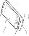
- Fig. 1illustrates an example monitoring environment including a perspective view of an example patient monitor 100 that can implement the various EWS features described herein.
- the patient monitor 100can be a pulse oximeter or pulse oximetry monitor.
- the patient monitor 100can be an example of the Root TM product available from Masimo Corporation TM of Irvine, California.
- the Root TM patient monitorcan work in conjunction with other Masimo TM devices, including Radical-7 TM or Radius-7 Pulse TM CO-Oximeters and Masimo Open Connect TM (MOC-9 TM ) measurements, and can feature Masimo SET Measure-through Motion and Low Perfusion TM pulse oximetry, rainbow SET TM pulse CO-Oximetry, Nomoline TM capnography and gas monitoring, SedLine brain function monitoring, O3 TM regional oximetry, SunTech TM blood pressure, and Welch Allyn TM temperature monitoring.
- Masimo TM devicesincluding Radical-7 TM or Radius-7 Pulse TM CO-Oximeters and Masimo Open Connect TM (MOC-9 TM ) measurements, and can feature Masimo SET Measure-through Motion and Low Perfusion TM pulse oximetry, rainbow SET TM pulse CO-Oximetry, Nomoline TM capnography and gas monitoring, SedLine brain function monitoring, O3 TM regional oximetry, SunTech TM blood pressure
- the patient monitor 100is shown with an optional docked portable patient monitor (PPM) 102.
- the patient monitor 100includes a display 104 and a docking station 106, which can mechanically and electrically mate with the portable patient monitor 102, each housed in a movable, mountable and portable housing 108.
- the housing 108includes a generally upright inclined shape configured to rest on a horizontal flat surface, although the housing 108 can be affixed in a wide variety of positions and mountings and comprise a wide variety of shapes and sizes. Patient monitors without docked portable patient monitors may be used in other examples.
- the display 104may present a wide variety of measurement and/or treatment data in numerical, graphical, waveform, or other display indicia 110.
- the display 104can occupy much of a front face of the housing 108, although the display 104 may comprise a tablet or tabletop horizontal configuration, a laptop-like configuration or the like.
- Other implementationsmay include communicating display information and data to a table computer, smartphone, television, or any display system currently available.
- the upright inclined configuration of Fig. 1presents display information to a caregiver in an easily viewable manner.
- the patient monitor 100can display an EWS.
- the EWScan represent an aggregation of vital signs and/or clinical observations and may represent the potential degree of patient deterioration.
- EWS protocols or scoring systemscurrently studied, such as Pediatric EWS (PEWS), Modified EWS (MEWS), and National EWS (NEWS).
- the EWS output by the patient monitor 100can be based on any of these publicly-available scoring systems or a customized scoring system, as will be discussed below.
- the publicly-available scoring systemscan use vital signs contributors-such as oxygen saturation, pulse rate, respiration rate, body temperature, and systolic blood pressure-and contributors input by clinicians, such as level of consciousness, use of supplemental oxygen, and urine output.
- the weighting and number of contributorsmay differ depending upon which EWS protocol is used.
- the patient monitor 100can be customized for various predefined EWS protocols, or hospitals can configure their own set of required contributors, and optionally their relative weights, to create an EWS protocol or scoring system unique to their care environments.
- the EWSmay be initiated by a clinician (using, for example, a display option of the patient monitor 100), and then may be automatically calculated by the patient monitor 100.
- the patient monitor 100may calculate contributor scores using measured values and/or clinician input, then combine these contributor scores into an aggregated EWS.
- the patient monitor 100can output the EWS and associated contributor scores in a readily interpretable, high-visibility display with intuitive, optional multi-touchscreen navigation for easy and adaptable use in hospital environments.
- Clinicianscan choose to have the patient monitor 100 act as a stand-alone device (not connected to a network) perform EWS calculations, helping assist spot-check-based nursing workflows. Or, clinicians can use the patient monitor 100 as a network-connected device that performs EWS calculations and transmits these calculations to an electronic medical record database (see, for example, Fig. 17 , discussed below).
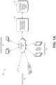
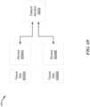
- FIG. 1Aan example of a clinical computing environment 100 is shown.
- the clinical computing environment 100may be implemented in one or more hospitals or other clinical facilities. Further, the clinical computing environment 100 can facilitate monitoring patients within their homes if such patients are using network-enabled monitoring equipment. Additional details of the example environment 100 are described in U.S. Pub. No. 2015/0106121, titled “Alarm Notification System,” filed Oct. 10, 2014 ("the '121 publication”), the disclosure of which is hereby incorporated by reference in its entirety. Any of the features described in the ' 121 publication can be implemented together with any of the features described herein.
- various patient devices 102, clinician devices 104, and nurse's station systems or kiosks 106can communicate over a network 109 with a multi-patient monitoring system (MMS) 110.
- MMS 110is an example of a remote server that can communicate with patient devices and clinician devices.
- the network 109may include a local area network (LAN), a wide area network (WAN), a public network (such as the Internet), a private network, or any combination of the same.
- the network 109can include a wireless and/or wired hospital network or a network that connects multiple clinical facilities.
- the patient devices 102may be any of the patient monitors or monitoring devices described herein and may include bedside monitors, ambulatory or mobile monitors, in-home monitors, and the like.
- the patient devices 102can be point-of-care devices, such as bedside devices or patient-worn devices.
- the patient devices 102can receive input from physiological sensors coupled with a patient and may measure parameters such as oxygen saturation or SpO2, respiratory rate, blood pressure, heart rate or pulse rate perfusion, other blood gas parameters, brain activity, brain oxygen saturation, any of the other parameters described herein, and the like.
- the patient devices 102can provide information about a patient's status, including current values of physiological parameters, waveforms, trend values, and historical values of physiological parameters over the network 109 to the MMS 110.
- the MMS 110can in turn store this data in an electronic medical records (EMR) system 120.
- EMRelectronic medical records
- the MMS 110can provide this data to the nurse's station systems 106.
- the nurse's station systems 106can include any type of computing device including, but not limited to, a desktop, laptop, tablet, phone or the like.
- the nurse's station systems 106may also include clinical facility kiosks such as computers on wheels (COWs) (which may use laptop or tablet computers), which may be dispersed throughout a clinical facility.
- COWscomputers on wheels
- the nurse's station systems 106can communicate with a plurality of patient devices 102 to receive information of a plurality of patients so that the nurse's station systems 106 can provide clinicians with the ability to monitor physiological parameter data for a plurality of patients.
- the clinician devices 104can include any mobile device, such as a laptop, tablet, cell phone, smartphone, personal digital assistant (PDA), or any other device.
- the clinician devicescan include desktop systems.
- the MMS 110can send alarms or messages representing alarms to the nurse's station systems 106 and/or the clinician devices 104.
- the patient devices 102may have network capability that enables the patient devices 102 to send the alarm notifications over the network 109 to the MMS 110, the nurse's station systems 106 and/or to the clinician devices 104.
- Some alarmscan include nonclinical alarms that may not represent that a physiological parameter has exceeded a threshold but instead may include information about a sensor that has been disconnected or otherwise has fallen off (often referred to as a probe-off condition), or a low battery of a patient device 152.
- Sensor disconnection or probe-offcan be detected using any of a variety of techniques, some examples of which are described in U.S. Pat. No. 6,360,114, filed March 21, 2000 , titled “Pulse Oximeter Probe-off Detector," and U.S. Pat. No. 9,750,461, filed December 20, 2013 , titled “Acoustic Respiratory Monitoring Sensor with Probe-off Detection,” the disclosures of which are hereby incorporated by reference in their entirety.
- Fig. 2Adepicts an example patient monitor display 200 including an EWS region 220, which can be a separate channel or group from other channels of physiological data on the display 200.
- the patient monitor display 200can be implemented in the patient monitor 100 of Fig. 1 .
- the display 200is a user interface that outputs values of physiological parameters for presentation to a clinician so that clinicians can make informed decisions about patients by knowing the status of patients' health.
- the display 200includes two general regions, a first region 210 and a second (EWS) region 220.
- the first region 210can include the majority of the display 200, and the second (EWS) region 220 includes a small horizontal section of the display below the region 210. The relative location of these two regions 210, 220 is unimportant and can be varied.
- the region 210includes several horizontal rows 212. Each row 212 can represent a channel of data obtained by calculating a physiological parameter from a physiological signal, for example, received from a sensor coupled to a patient. Several rows 212 include numbers representing physiological parameter values (such as 97 for SpO 2 percentage and 112 for pulse rate). In addition, the rows 212 include graphs that depict trend lines corresponding to those parameters over time.
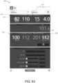
- Fig. 2Bdepicts an example close-up of the second region 220 (with different scores, explained below, shown for illustration purposes).
- the second region 220depicts a plurality of boxes 220 with numbers inside the boxes.
- Each box 220is above the name of one of the parameters listed in the first region 210.
- a first box 222is above the parameter SpO 2 and has the number 0 in it.
- the next boxis above the PR, or pulse rate, parameter and has the number 2 in it, and so on.
- a larger box 224that includes the EWS-here, having a value 8.
- the EWS value of 8is the sum of the numbers in the boxes 222 in this example.
- Each of the numbers in the smaller boxes 222can be considered a contributor score which contributes to the EWS in the box 224.
- Each contributor scorecan represent a severity level of the physiological parameters depicted in the region 210. Some of the contributor scores correspond to parameters that are not shown in the region 210, such as LOC or level of consciousness and supplemental oxygen (Sup.O 2 ). The input of these scores may be performed by clinicians manually and will be discussed in greater detail below.
- the contributor scorescan range from 0 to 3, with 0 representing the least severe and 3 representing the most severe. This scale is somewhat arbitrary and may be changed in other implementations.
- the higher the contributor scores in any given box 222represents a higher severity level for the corresponding physiological parameter.
- a very high or a very low pulse ratemay represent a greater degree of severity than an average pulse rate.
- the higher or lower the extreme of the pulse ratethe higher the pulse rate contributor score might be.
- Other physiological parametersmay have different scales, but in general, the worse the parameter value (for example, corresponding to worse health status of the patient), the more severe the contributor score may be.
- the resulting EWSwhich may be an aggregation of the contributor scores, can therefore directly reflect the severity of multiple measured physiological parameters.
- the EWScan represent a rough indication of the health status of the patient.
- the lower the EWSthe greater the likelihood that the patient is in better health than with a higher score.
- a higher scorereflects that, likely, multiple of the contributor scores are relatively high.
- pulse ratehas a score of 2, respiratory rate 1, temperature 2, and level of consciousness 3, resulting in an EWS of 8. This EWS indicates that greater attention may be needed for the patient than if the EWS were lower.
- the boxes 222 and 224 around the scoresare of course optional but help to draw visual attention to the individual contributor scores in their EWS.
- the color of the boxes 222may correspond directly to the values of the contributor scores within the boxes 222.
- the color of the EWS box 224may correspond to the value of the EWS in the box 224.
- one color schememay be represented with green as a low score, yellow as a slightly higher score, orange as a higher score than yellow, and red as a most severe score.
- colors and numbers representing the values of the physiological parameters in the box or region 210an easy and readily understandable display method can be provided for conveying the health status of the patient to a clinician.
- a cliniciancan look at the EWS region 220 of the display and readily grasp whether or not the patient is likely in need of greater medical assistance than he or she is currently receiving.
- Viewing the EWS region 220may be easier than looking at the region 210 and deciphering several different physiological parameter values, many of which may be on different scales and thus hard to interpret together.
- the physiological parametershave different scales-for instance SpO 2 goes from 0 to 100% while pulse rate may range from approximately 40 or lower to well over 200-a clinician may need greater training to understand and interpret the physiological parameter values than a clinician may need to interpret the contributor scores and the EWS.
- a clinician with perhaps less trainingmay be able to glean more information about the health status of the patient than the clinician might have been able to otherwise, merely by looking at the EWS region 220. Even clinicians with more training can more quickly glean information about patient health by reviewing the EWS region 220.
- the region 210 and the region 220can be two separate regions that may or may not overlap.
- the region 220can be in a horizontal line or horizontal section and can group together some or all of the contributor scores and the EWS in that section. By doing so, a clinician can readily visually perceive the various contributor scores and EWS together.
- a clinicianwould have to hunt and peck to find the different contributor scores and EWS. Of course this would take longer to identify the different contributor scores.
- the cliniciancan more quickly ascertain the health status of the patient and therefore more quickly react to the needs of the patient.
- the horizontal row of contributor scores and EWS valuemay instead be vertical, but nevertheless grouped together.
- the contributor scoresmay be grouped together in multiple rows in some type of rectangular or square matrix or the like.
- any combination of the contributor scores and EWS graphicallymay be provided so long as they are grouped together in some fashion so that they are readily visually perceptible to a clinician.
- the EWSmay be in a separate area of the display from the grouped together contributor scores or may be grouped together with the contributor scores as shown.
- the EWScan be calculated or derived using any of a variety of currently available warning score systems, as discussed above (such as MEWS or NEWS). Further, as will be described in greater detail, the hospital or administrative staff may be provided functionality through the medical device or patient monitor 100 or a separate device in communication thereof, to customize the parameters used in the EWS as well as optionally other aspects of the EWS.
- a last time calculated value 226is shown underneath the EWS 224.
- the last time calculated value 226depicts when the last time the EWS was calculated and may be used when the EWS is calculated in a spot check fashion, on demand at the request of a clinician.
- the EWScan be calculated continuously, which can include calculating the EWS automatically along with changes in the physiological data. Continuous does not necessarily mean in an analog sense, where it would always be changing, but rather, may be performed using discrete calculations that are rapid enough (such as once a second or once a minute) to be relatively more continuous than infrequent spot checks.
- the continuous version of the EWS calculationmay be useful to give the clinician a moment-by-moment indication of changing health status of the patient.
- a spot check of the EWSmay also be calculated periodically in an automatic fashion, where the EWS is calculated for instance every hour or every two hours or upon clinician request.
- each of the user interfaces shown in Figs. 2A and 2Bincludes one or more user interface controls that can be selected by a user, for example.
- each of the user interfaces shownmay be output for presentation by electronic hardware as graphical user interfaces.
- the user interface controls shownare merely illustrative examples and can be varied. For instance, any of the user interface controls shown may be substituted with other types of user interface controls that provide the same or similar functionality.
- user interface controlsmay be combined or divided into other sets of user interface controls such that similar functionality or the same functionality may be provided with very different looking user interfaces.
- each of the user interface controlsmay be selected by a user using one or more input options, such as a mouse, touch screen input (for example, finger or pen), or keyboard input, among other user interface input options.
- the EWS calculation processmay be implemented by a patient monitor such as the patient monitor 100. More generally, the EWS calculation process 300 can be implemented by any processor or computer system that can perform processing calculations. For instance, the EWS calculation process 300 may be implemented by a remote system, whether in the cloud or in a dedicated server in a hospital, which is in communication with the patient monitor such that the EWS is calculated remotely and then potentially transmitted locally to a patient monitor, nurse's station or the like (see, for example, Fig. 17 ). Or, the process 300 could be implemented by a mobile phone, tablet, laptop, or other computing device having a processor. Thus, the process 300 will be generally referred to as implemented by a processor.
- a processorcalculates physiological parameters from physiological signals obtained from the patient.
- the physiological signalsmay be obtained from any of a number of sensors including optical sensors, piezoelectric sensors, electrical sensors, biomechanical sensors, or combinations of the same.
- optical sensorsmay provide parameters such as oxygen saturation or SpO 2 , pulse rate, pleth variability index (PVI), perfusion index (PI), total hemoglobin or SpHb, methemoglobin or SpMet, carboxyhemoglobin or SpCO, among others.
- a piezoelectric sensormay be used to calculate parameters such as respiratory rate and pulse rate.
- Electrical sensorscan be used to calculate parameters such as respiratory rate, heart rate, and other ECG-related parameters obtained from the electrocardiogram.
- Biomechanical sensorssuch as bioimpedance sensors, can be also used to capture parameters like respiratory rate.
- Other example parametersmay be calculated using any of a variety of sensors, such as blood glucose level (using an optical sensor or finger prick sensor), blood pressure (using a biomechanical sensor such as an oscillatory cuff or an optical sensor), and temperature (using a temperature probe or the like), among others. Any number of physiological parameters may be selected to be calculated as a basis for inclusion in an EWS. Seven parameters, nine parameters, or 14 parameters can be selected in various implementations. More or fewer parameters may instead be selected. Further, the number and type of parameter selected may be chosen by a clinician or the hospital.
- the processorcalculates contributor scores for each parameter.
- Contributor scoresmay have a variety of values as discussed above. With respect to Fig. 2 in one example, these values can be integers ranging from 0 to 3. They need not be integer values, although integer values may be easier to see and interpret on a display than fractional values.
- the contributor scores(or EWS itself) need not be numbers, but instead could be alpha values or alphanumerical values, or even symbols (such as red, yellow, and green filled circles ranging from most severe to least severe contributor scores).
- the contributor scoresmay be calculated for each parameter by looking up the value of the parameter in a lookup table or the like, where different values fall within a range that maps to a specific contributor value.
- an oxygen saturation value from 95% to 100%may correspond to a low risk score such as 0, whereas an oxygen saturation value of below 85% may correspond to a very high risk value such as a 3, with other values of oxygen saturation falling in-between those two extremes of contributor scores.
- the ranges of physiological parameter values that correspond to the different scoresmay also be configured by a user, such as a clinician or hospital staff as discussed in greater detail below (see Fig. 10 ).
- Manual parameterscan include parameters entered manually by a clinician, which may be measured using other instruments such as a temperature probe or parameters that are observed by a clinician without using an instrument (such as LOC, which may correspond to the degree to which a patient is aware of their surroundings). If any manual parameters are entered at block 306, then the process 300 loops back to block 304, where parameter scores or contributor scores are calculated for each of those manual parameters in a similar fashion to the automatic parameters.
- the process 300proceeds to block 308, where the processor computes an EWS from the contributor scores.
- Thismay include a simple summation or a more complex aggregation.
- the aggregationmay be a summation or may be a weighted summation where different weights are applied to different parameters. Some parameters may be considered more important for assessing the overall health status of the patient than others, and thus, greater weights may be applied to these parameters, for example, in the form of a coefficient. Other scales may of course be used, and weighting schemes may be linear or exponential.
- the processoroutputs the EWS and the contributor scores together on the display, such as in the manner discussed above with respect to Fig. 2 or other examples discussed herein.
- the processorcan output the EWS and the contributor scores together but apart in some way from the actual parameter values.
- parameter valuesmay be in one region of the display-which may but need not be demarcated as such-which is separate from a region including the contributor scores and the EWS score (which also may but need not be demarcated).
- the contributor scorescan be together but separate from the EWS score on the display.
- Figs. 4 and 5depict additional example patient monitor displays 400, 500.
- Each of the patient monitor displays 400, 500may be implemented by a patient monitor such as the patient monitor 100 of Fig. 1 .
- Each of the patient monitor displays 400, 500are similar to the patient monitor display 200 of Fig. 2 .
- the example patient monitor display 400includes two buttons, 410, 420, which provide additional functionality. These buttons 410, 420 may be accessed by selecting the button 230 (see Fig. 2 ). The buttons 410, 420 may be dismissed by selecting the button 430 in Fig. 4 .
- the button 410can be a clear button which can be used to clear the EWS and contributor scores shown in Fig. 4 . Selection of the clear button 410 can result in these scores being reset as shown in Fig. 5 in the region 510.
- the region 510includes a horizontal display as in Fig. 4 and Fig. 2 , where the EWS and contributor scores would be, but in their places are lines indicating that these scores have been reset and are blank.
- the button 420can be used to calculate a new set of contributor scores and/or EWS. Selection of the button 420 can cause the contributor scores to update automatically and the EWS to update automatically directly on the display 400. After selection of the button 420, the buttons 410 and 420 can disappear to reveal the full set of contributor scores and EWS (for example, as in Fig. 2 ). However, selecting the button 420 can cause another menu to be displayed, from which the EWS can be calculated (as in, for example, Fig. 6 ). More generally, selecting the button 420 can cause a spot check calculation ultimately to be made.
- buttons 410 and 420are displayed in the same horizontal row as the EWS and contributor scores, they need not be, but instead could be displayed elsewhere on the display 400.
- Figs. 6 and 7depict additional example patient monitor displays 600, 700 that can provide functionality for inputting manual parameters used to calculate an EWS.
- the display 600may be reached by selecting the button 420 to calculate an EWS from the display 400.
- the example display 600 shownincludes three general regions, a region 610, a region 620 and a region 630. (Viewed another way, there are two regions-a region 610 and a region defined by elements 620 and 630.)
- the region 610includes a list of parameters for which contributor scores may be calculated as well as a blank spot for an EWS (populated in Fig. 7 , discussed below). Some of these parameters have contributor scores already calculated, including SpO 2 , pulse rate, and respiratory rate. These scores are shown as already calculated because the parameter values can be measured from sensors and therefore may be calculated without manual intervention from a clinician. The values of these physiological parameters are listed below in the region 630.
- the region 620includes user interface controls for specifying various parameters measured manually or independent of the physiological sensors connected to the patient or with other physiological sensors that the clinician may directly use with the patient. Examples of these parameters include temperature, blood pressure (systolic or otherwise), level of consciousness and supplemental O 2 , among others. Slider controls allow temperature and blood pressure to be set by moving the slider from left to right, and dropdown box controls allow the level of consciousness and supplemental O 2 settings to be computed or selected.
- the region 630can also allow manual editing of the physiological parameters shown. For instance, if a clinician manually measures a patient's pulse rate (PR) and identifies a different pulse rate than was obtained automatically from a sensor, the clinician can enter the manual measurement in the region 630.
- PRpatient's pulse rate
- the display 700shows an example of the parameters in the region 620 of Fig. 6 now inputted by a clinician. Because these parameters have been inputted in this example, contributor scores have been calculated for them in the region 610, and an EWS has been calculated based on the contributor scores.
- Fig. 8depicts another example patient monitor display 800.
- This display 800is similar to the displays shown in Figs. 2 and 4 described previously. Unlike those displays, however, the display 800 includes a user interface control 810 for sending EWS data (including the EWS, contributor scores, parameter values, or combinations of the same) to an electronic medical record database (see Fig. 17 ).
- the user interface control 810is a button. Selecting the control 810 can cause any of the EWS data shown in this display 800 to be sent to the EMR database.
- FIG. 9Aanother example patient monitor display 900 is shown that can be output in response to the user interface control 810 of the display 800 being selected by a clinician.
- This displayis much like the displays 600, 700 of Figs. 6 and 7 .
- the display 900includes three regions-910, 920, and 930-that have similar functionality as the regions 610, 620, and 630 of Fig. 6 .
- these regionsare shown populated with scores, parameter values and the like, whereas they may start off by having at least some fields or scores empty (as in Fig. 6 ).
- another example parameter, glucoseis shown to illustrate that the manual entry parameters may differ from those shown in Fig. 6 .
- Another difference in the display 900is that an approve button 940 is provided for approving these parameters for submission to the EMR. Upon selection of this button, data shown can be sent to the EMR database (see, for example, Fig. 17 ).
- Fig. 9Bshows essentially the same interface of Fig. 9A , except this interface 950 includes an action list 960 that includes instructions.
- the text of these instructionsmay be based on a severity level of the EWS displayed or may instead be general instructions to the clinician. Either way, the instructions may be customized or defined by the hospital (for example, by administrative staff).
- the action list 960can be displayed by selecting a button or performing some action (such as swiping) in the interface 900 of Fig. 9A .
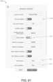
- Fig. 10depicts another example patient monitor display 1000 providing functionality for configuring EWS parameters.
- the display 1000can be implemented in a patient monitor such as patient monitor 100. More generally, the display 1000 can be implemented on any computing device and need not be implemented on a patient monitor.
- the patient monitor display 1000can provide clinicians or hospital staff with the functionality to specify which parameters should be included in calculating an EWS. For example, the display 1000 can enable selecting which parameters should be used to compute contributor scores. Further, the display 1000 can enable a user to specify what ranges of those parameters result in certain contributor scores.
- the display 1000is divided into two example sections: parameter selection (for selecting parameters to be contributors to EWS) and parameter ranges (for specifying ranges corresponding to contributor scores).
- a box 1010lists available parameters which may be selected, for example, by selecting any of the available parameters (for example, via touch or other input) and then selecting an add button 1030 to add those parameters to a selected parameters box 1020.
- Parameters in the selected parameters box 1020can be used to compute the EWS. Any number of parameters may be selected for addition to the box 1020 from the available parameters.
- Available parametersmay also be defined by the hospital and may include parameters that are measured continuously using physiological sensors, parameters measured with spot checks using physiological sensors such as temperature or blood pressure, and/or parameters measured by observation of a clinician such as level of consciousness.
- the selected parameters in this exampleinclude SpO2, pulse rate, respiratory rate, temperature, and systolic blood pressure. With this selection made, a patient monitor can use each of these parameters to compute contributor scores and an EWS.
- an example set of user interface controls 1040which are sliders in this example, are shown for the SpO 2 parameter.
- the slider controls 1040can enable a user, such as a clinician or hospital staff, to specify ranges for various severity levels corresponding to contributor scores. These ranges are shown having been selected corresponding to different severity levels: green, yellow, orange and red. These levels may correspond to contributor scores 0, 1, 2 and 3 discussed above.
- the number of ranges and the actual colors or scoresmay vary.
- Some parametersdo not lend themselves directly to ranges but rather have a series of values that could be mapped one-to-one to contributor scores by a user using the display 1000. For example, level of consciousness may have single values that users can select from the display to correspond to different contributor score severity values.
- the display 1000could be adapted to provide functionality for a user to specify weights to apply to contributor scores.
- the weightscan reflect the relative importance of contributor scores and may be used to combine the contributor scores into a single EWS using a weighted combination.
- a default weight of 1can be effectively applied to each contributor score such that adding each contributor score results in the EWS.
- itcould be desired to create a normalized scale for EWSs such as 0 to 1, 1 to 10, 0 to 100, or some other range.
- the parameters contributing to the EWScould be weighted to produce a normalized score. If additional parameters are added, the weights may be automatically adjusted by the patient monitor to preserve normalization.
- the weightingscould be selected by users (for example, clinicians or staff) to emphasize which parameters reflect a greater indication of patient health. For instance, vital signs may be prioritized above non-vital signs as being more indicative of the patient's health status. But any number of parameters may be weighted higher than others to meet a hospital's needs and goals for measuring patients' health. Further, weights and ranges may be set differently for different segments of the patient population. For example, different weights may be selected based on age (such as adult versus neonate), gender, and based on different co-morbidities or diseases. A patient who has a particular disease may have a different set of ranges or weights applied to that patient, which may be defined in a user interface such as the display 1000.
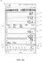
- Fig. 11depicts another example patient monitor display 1100 including an example EWS region, channel, or group 1110 that differs from the previous examples discussed above. Like the other displays, such as display 200 in Fig. 2 , the display 1100 depicts numerous physiological parameter values in a first region 1102 and depicts EWSs in a second region 1110. The difference here with Fig. 2 is that the EWSs in the region 1110 includes two rows 1112 of contributor scores. Like the display 200, the contributor scores shown may be represented vertically in multiple columns instead of horizontally in multiple rows.
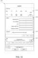
- FIG. 12another display 1200 is shown that may be accessed by selecting the EMR push button 1120 of Fig. 11 .
- the display 1200is also similar to the displays 600 and 900 discussed above with respect to Figs. 6 and 9A .
- the display 1200includes two regions, 1210 and 1220, which can correspond to the regions 610, 910 and 620 and 920 (respectively).
- the region 1210can represent contributor scores and an EWS.
- the region 1220includes dropdown boxes for manual input of various parameters.
- the new regions 1230 and 1240can provide instructions for performing a spot check of different parameters using separate sensors-temperature and noninvasive blood pressure (NIBP) in this example. Following the instructions in those regions, measurements may be taken. Then, a display such as in Fig. 13 (the display 1300) may be shown, which can indicate that two measurements are in the process of being taken in the regions 1230 and 1240. In addition, the regions 1210 and 1220 in the display 1300 include contributor scores and an EWS that have been populated.
- NIBPnoninvasive blood pressure
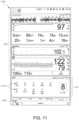
- Fig. 14another example patient monitor display 1400 is shown that depicts the regions 1230 and 1240 now with populated measurements that have been obtained by the temperature and NIBP sensors.
- the blood pressure measurements in this exampleinclude a mean arterial pressure (MAP), pulse rate derived from the blood pressure, and systolic and diastolic blood pressure measurements. Any of these measurements may be used to represent blood pressure measurements used to calculate the contributor score for blood pressure.
- the pulse rate measurement derived from the blood pressure sensorcan be used in place in, or in combination with, the pulse rate derived from another sensor (such as an optical or ECG sensor) when calculating a contributor score for pulse rate.
- the display 1400also includes a user interface control 1412 that may be selected (for example, by swiping) to display an action list as shown in Fig. 15 , which depicts a similar display 1500 as shown in Fig. 14 , except that an action list 1560 is shown.
- the action list 1560may have the same functionality as the action list described above with respect to Fig. 9B , and the user interface control 1562 can be selected (for example, by swiping) to allow a user to dismiss the action list.
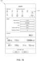
- FIG. 16another example patient monitor display 1600 is shown that is nearly identical to a patient display 1400 of Fig. 14 , except that one of the contributor scores 1602 has an emergency value represented with the letter E.
- This contributor scorecan correspond to the level of consciousness parameter.
- the level of consciousness value in this exampleis "pain," which in this example is an emergency value.
- the emergency valueessentially exceeds the highest contributor score numerical value that is typically used.
- An emergency score for any one contributor scorecan cause the patient monitor to assign an emergency value to the EWS, as noted in box 1610.
- an emergency score for one contributor scoremay not override the EWS but is merely shown separately from the EWS, which can be calculated as usual.
- Fig. 17depicts an example environment 1730 for communicating EWS data to an electronic medical record database and to a nurse's station system.
- the example environment 1730 of Fig. 17includes a patient monitor 1700 in communication with a gateway 1750, which can be in communication with an EMR 1752.
- the EMR 1752is in communication with a hospital system 1754, which is in communication with a nurse's station system 1756.
- the patient monitor 1700is an example representation of any of the patient monitors discussed herein, such as the patient monitor 100.
- the patient monitor 1700can be used to implement any of the features described herein, just like the patient monitor 100.
- the gateway 1750may be a server or appliance that collects data from multiple patient monitors and forwards that data to the EMR 1752.
- the EMR 1752is an example electronic medical record database that stores patient medical data.
- the hospital system 1754may be a server or set of servers in communication with the nurse's station system 1740 as well as in communication with other nurse's station systems throughout the hospital.
- the hospital system 1754may manage electronic scheduling for clinicians as well as paging or other features.
- the gateway 1750 and the hospital system 1754may be part of the same system.
- the gateway 1750 and/or the hospital system 1754may be examples of the MMS 160 described above with respect to Fig. 1A .
- the various devices and systems showncan communicate across a network, such as a hospital network, the Internet, or combinations of the same.
- the patient monitor 1700can be in communication with one or more non-invasive sensors coupled to a patient (not shown).
- the patient monitor 1700can be used for continuous or spot check monitoring of one or more physiological parameters.
- the patient monitor 1700may include hardware and software that processes physiological signals received from the one or more non-invasive sensors to compute contributor scores and early warning scores, for example, based on the process 300.
- the patient monitor 1700can communicate EWS data (including, for example, both contributor scores and an EWS) to the gateway 1750 across the network, which can format the data for storage in the EMR 1752 (for example, according to an HL7 data specification).
- the hospital system 1754can access the EWS data and can forward this data to the nurse's station system 1740, so that clinicians not close to the patient monitor can be informed.
- the patient monitor 1700may also communicate the EWS data directly to clinician devices (not shown, such as mobile phones, tablets, laptops, or desktops) over the network.
- the nurse's station system 1740can receive the EWS data from the hospital system 1754 and output the data on a display 1762.
- the display 1762can include data 1760 corresponding to a plurality of patients as well as detailed data 1764 corresponding to a specific patient.
- the EWS datacan be shown as data 1766 in the detailed data 1766 and may include just the EWS score (this example) or the entire set of EWS data (including contributor scores), which may be formatted as shown in Fig. 2B or in some other manner as discussed above.
- Fig. 18illustrates a simplified example hardware block diagram of the patient device 100 of Fig. 1 .
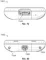
- the housing 2108 of the patient device 100can position and/or encompass an instrument board 2302 (which may be a circuit board), the display 2104 (corresponding to the display 104), memory 2304, and the various communication connections, including serial ports 2210, channel ports 2212, Ethernet ports 2305, a nurse call port 2306, other communication ports 2308 including USB ports or the like, and a docking station interface 2310.
- Various of these portscan communicate with one or more physiological sensors or other medical devices and are described in more detail in U.S. Patent No.
- the instrument board 2302comprises one or more substrates including communication interconnects, wiring, ports and the like to enable the communications and functions described herein, including inter-board communications.
- An example core board 2312includes the main parameter, signal, and other processor(s) and memory
- a portable monitor board (“RIB") 2314includes patient electrical isolation for the monitor 2102 and one or more processors
- a channel board (“MID") 2316controls the communication with the channel ports 2212 including optional patient electrical isolation and power supply 2318
- a radio board 2320includes components configured for wireless communications.
- the instrument board 2302may include one or more processors and controllers, busses, all manner of communication connectivity and electronics, memory, memory readers including EPROM readers, and other electronics recognizable to an artisan from the disclosure herein. Each board comprises substrates for positioning and support, interconnect for communications, electronic components including controllers, logic devices, hardware/software combinations and the like to accomplish the tasks designated above and others.
- the instrument board 2302may comprise a large number of electronic components organized in a large number of ways. Using different boards such as those disclosed above may provide organization and compartmentalization to the complex system. Of course, using different boards for different functions is optional.
- a third approachis a hybrid of these two where a patient is monitored continuously for a short period of time to obtain a snapshot of physiological information.
- Continuous monitoringcan involve taking measurements of a patient continuously or at least approximately continuously over an extended period of time. This type of monitoring is commonly done on hospital floors, in emergency rooms, and in other settings where a patient's vital signs or other physiological parameters need to be observed over a period of time.
- measured valuesare frequently compared with predetermined criteria to identify any changes in the measured values that might warrant clinician attention. It is common, for instance, in continuous monitoring to alarm if a patient's measurements have exceeded bounds of safety such that attention from a clinician (for example doctor or a nurse) may be warranted.
- Spot check measurementsare typically performed as a single measurement at one point in time, instead of several measurements over a period of time as in continuous monitoring.
- a clinicianmay perform a spot check measurement by placing a sensor on a patient (or by manually observing some characteristic of the patient) and recording a measured physiological parameter value on the patient's chart (paper or electronic).
- spot check measurements(sometimes referred to herein simply as "spot checks") may be performed in a hospital or in any other setting.
- Cliniciansmay input spot check measurements into a paper chart or into a computing device, such as a computer on wheels (COW), tablet, or other mobile device.
- a computing devicesuch as a computer on wheels (COW), tablet, or other mobile device.
- COWcomputer on wheels
- One problem with manually inputting spot check measurements in this manneris that it can take a clinician's focus away from the patient. While the clinician is inputting patient data, the clinician typically is not directly observing the patient and is instead focused on manual entry. Patients may perceive clinicians as ignoring them or less attentive to them while clinicians input parameters. Further, manual entry of spot check values can be cumbersome and time intensive for clinicians. Thus, both patients and clinicians could benefit from reducing or eliminating manual entry of spot checks.
- Some benefits of avoiding or reducing manual chartingcan include better patient care due to more attentive clinicians, more time for clinicians to spend with patients, and less time on mundane tasks and fewer clerical errors.
- Example systems and methods for performing spot check measurements described hereincan reduce or alleviate some or all of the problems with existing spot check measurement approaches. These spot check measurements may be performed anywhere, including in a hospital, home, or other care setting.
- the spot check measurementscan involve applying a sensor or sensors to a patient, obtaining measurements, automatically sending the measurements to the patient's electronic chart (for example, in an EMR database), and/or optionally outputting some or all measurements audibly.
- Spot check measurementscan be performed automatically in response to a sensor being removed or upon a button press-which can free clinicians to focus on patients. Automatically saving measurements to patients' charts instead of entering measurements manually can permit clinicians to focus on patients' needs. Further, audibly outputting parameter measurements can free clinicians to focus on patients rather than looking at measurements on a display.
- Figs. 19 through 34depict example user interfaces that can implement the spot check features described above (further, additional examples are discussed below with respect to subsequent figures). These useful interfaces are capable of being displayed on any computing device, for example, the patient device 100 described above with respect to Fig. 1 or any of the other devices described herein. Further, each of the user interfaces shown in Figs. 19 through 34 may be implemented with any of the user interface features described above. Thus, although specific example user interfaces are shown, having specific user interface controls, different user interface controls, designs, and features may be used to implement the spot check techniques described herein.
- a user interface 1900is shown, which is an example splash screen that may be displayed on reboot or boot up of the patient device 100.
- the user interface 1900indicates that the device is in spot check mode and that continuous monitoring will be suspended.
- This splash screen 1900may be displayed when the patient monitor 100 is selected to be in spot check mode instead of continuous monitoring mode.
- the user interface 1900is optional.
- a menu optioncan be accessible from any of the displays described above, which can be selected to cause the patient device 100 to reboot into a locked spot check mode. It can be advantageous to have a device dedicated to spot check mode or otherwise locked into spot check mode so that it may be used for this purpose and not confused with devices that are used for continuous monitoring.
- a spot-check dedicated monitormay be put on a wheeled cart or may be carried from room to room in a hospital or other clinical setting, where it can be used to measure spot check parameters of several different patients.
- a monitor or patient device in spot-check modemay be used with many patients over a short period of time.
- the spot check modemay be changed back to continuous mode by a clinician selecting another menu option (not shown). If a clinician were to select continuous mode, the patient device 100 may be rebooted into that continuous mode.
- the user interface 2000is an example of a clinician login screen and depicts an indication or a message for a clinician to scan or type the clinician's username and password in fields 2010.
- the cliniciancan scan his or her employee badge.
- the clinician's usernamemay be automatically populated in the user interface 2000. Scanning of the badge may be performed using an optical scanner, such as the scanning technology described in U.S. Pub. No. 2015/0106121, filed October 10, 2014 , titled "Alarm Notification System" (attorney docket MAS. 963A), the disclosure of which is hereby incorporated by reference in its entirety.
- the clinician's badgemay include a wireless chip (such as a radiofrequency identification or RFID chip), which when in proximity to the patient device 100, can be read by the patient device 100 so as to automatically log in the clinician.
- a wireless chipsuch as a radiofrequency identification or RFID chip
- Examples for performing this RFID-based loginare described in greater detail in U.S. Pub. No. 2014/0135588, filed September 19, 2013 , titled "Medical Monitoring System” (attorney docket MAS.756A2P2), the disclosure of which is hereby incorporated by reference in its entirety.
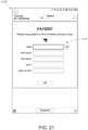
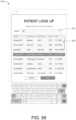
- FIG. 21another example user interface 2100 is shown.
- This user interface 2100is an example patient login screen like the clinician login screen described above with respect to Fig. 20 .
- the patient login screen 2100provides fields 2110 to enter patient information. It also permits scanning of a patient bracelet to automatically populate those fields 2110, using, for example, the scanning technology described in U.S. Pub. No. 2015/0106121 , referred to above, or the wireless technology described in U.S. Pub. No. 2014/0135588 , referred to above.
- Fig. 22depicts another example user interface 2200 that is identical to the user interface 2100 except that the fields 2110 are populated with patient information.
- a keyboard 2220is shown, which is an example of a software (soft) keyboard that can be used to manually enter patient information.
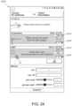
- Fig. 23depicts another example user interface 2300.
- the user interface 2300is an example measurement initiation screen.
- the measurement initiation screen 2300can provide instructions to the clinician for attaching sensors to patients and beginning measurements. These instructions are provided in areas 2330 of the display, which include instructions for application of an optical sensor 2331, application of a temperature sensor 2333, and an application of a blood pressure sensor 2335.
- the blood pressure sensor 2335 instructionsare also accompanied with a button 2332 which, when pressed, can cause blood pressure cuff inflation to begin.
- Below the areas 2330is a manual entry area 2350 that permits entry of some manual parameters, which can include parameters observed by a clinician without use of sensors (or optionally with the use of sensors).
- LOClevel of consciousness
- O 2supplemental oxygen
- pain scaleglucose
- glucoseglucose
- action menus 2340may be selected if desired to cause action menus to be displayed.
- Fig. 24a nearly identical example user interface 2400 is shown as the user interface 2300 except that the action menus 2340 have been expanded to show options 2410 for selecting adult, pediatric, or neo (short for neonate) options for measurement. These different options 2410 may cause different measurement algorithms or the like to be performed for different age ranges of patients.
- User interface controls 2420permit the action menus to be closed.
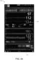
- FIG. 25another example user interface 2500 is shown, which is a continuation of the user interfaces 2300 and 2400.
- the user interface 2500indicates that measurements are in process.
- the areas 2330show different information depending on the type of sensor employed.
- measurementsare displayed for at least some parameters including SpO 2 , pulse rate, and perfusion index (PI).
- PIperfusion index
- respiratory rateis also shown as an available measurement, it is not yet calculated in this example. This respiratory rate may be taken based on the photoplethysmograph (or photopleth, or simply pleth) obtained from the optical sensor.
- the temperature and blood pressure measurements in the areas 2330have not yet been completed and thus are shown as "measuring" in the depicted example user interface 2500.
- each of the different parametershas been populated by a clinician.
- FIG. 26another example user interface 2600 is shown that is a continuation of the interface 2500 and shows measurements for temperature and blood pressure populated in addition to the optical measurements discussed previously. Likewise, the respiratory rate based on the pleth measurement is now also populated.
- a snapshotmay now be taken by selecting a snapshot button 2610 at the bottom of the screen. Selection of this button can cause the particular parameter values shown to be saved as snapshot parameters. Further, the optical parameters may also be frozen and stop measuring continuously once the snapshot button 2610 is selected or when the optical sensor is removed from the patient, as will be discussed in greater detail below.
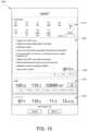
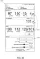
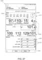
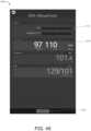
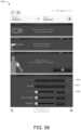
- FIG. 27another example user interface 2700 is shown.
- This user interface 2700is an example snapshot screen, which shows the results of selecting the snapshot button 2610 in Fig. 26 or the result of removing the optical sensor.
- the snapshot screenincludes measurements in the areas 2330 that are also shown in Fig. 26 .
- another area 2710is shown that presents an early warning score 2724 as well as individual contributor scores 2722 as described in greater detail above.
- the shapes around the contributor scores 2722 and the early warning score 2724-which differ from those in earlier figures-suggest an appearance of three-dimensional boxes.
- any kind of shapes or indicatorsmay be used to indicate the severity of the contributor scores and early warning scores. The shapes can even be omitted in favor of coloring the contributor scores 2722 and or early warning score 2724 themselves according to severity level.
- a menu 2726is also provided for depicting EWS actions as discussed above (see, for example, Fig. 15 ).
- buttons 2732may be selected to manually change the data. It may be desirable for a clinician to change a measured parameter if the clinician believes that the measured parameter does not accurately reflect a physiological parameter of the patient.
- the clinicianmay, for instance, decide to do an independent manual measurement. For example, the clinician may do a traditional pulse rate measurement at the patient's wrist or carotid artery and may determine to use that measurement instead of the measurement obtained from the optical sensor.
- any number of measurementsmay be so editable.
- the measurements that may be editablemay be selected by the hospital or clinical staff prior to deploying the patient device 100, for example, according to hospital policies.
- Pulse rate, respiratory rate, and temperatureare some examples of parameters that can be overwritten manually using the user interface 2700 (in addition to the manual parameters in the area 2350 below).
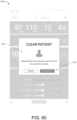
- An example selection of one of the buttons 2732 to perform manual entrycan cause an example user interface 2900 or the like to be shown as depicted in Fig. 29 .
- an overlay 2901 including user interface controls 2910can permit manual change of the data (blood pressure in this example).
- a send button 2740is also shown.
- This button 2740may be selected to cause a snapshot of the measurements shown to be sent as spot check measurements to the patient's chart stored, for example, in the electronic medical record database (see, for example, Fig. 17 ). Selection of the button 2740 can cause a user interface such as the example user interface 2800 of Fig. 28 to be shown. An overlay 2801 in the user interface 2800 indicates that the spot check data was successfully sent to the EMR.
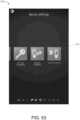
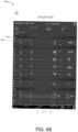
- FIG. 30an example previous spot check list user interface 3000 is shown.
- the previous spot check list 3000depicts a plurality of patient names 3010 organized by date, which may be selected to view spot checks for a particular patient.
- Alert icons 3020are shown next to some patients whose parameters or early warning scores may be outside of an acceptable or safe range and therefore perhaps warrant particular attention by a clinician.
- the alert icons 3020can be used to indicate that a patient's spot check measurements have been saved to the patient monitor but have not yet been sent to the EMR, for example, due to the patient monitor being out of wireless network range.
- User selection of one of the patient names 3010may cause a user interface 3100 of Fig. 31 to be shown.
- the user interface 3100is similar to the previous spot checks interface 3000 of Fig. 30 except that one of the patients 3010 has been expanded to show this patient's previous spot checks 3110, organized by date and time. Those listings showing times may only represent spot checks taken the current day. Selection of any of these spot checks can result in a user interface being displayed such as any of the interfaces shown in Figs. 32 through 34 .
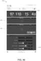
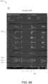
- Figs. 32 through 34illustrate additional example interfaces 3200 through 3400 that depict various trend views of previous spot checks.
- These interfaces 3200depict patient information 3210, including manual parameters entered as described above, as well as rows 3220 of spot check trend data.
- the spot check trend data in the rows 3220is organized in this example as a series of dots, with each dot having a number beneath it representing a particular measurement taken at a particular time.
- the measurement timescorrespond to a timeline 3230 shown at the bottom of the display.
- the dots representing parameter measurementscan be connected with other dots to represent trends over time.
- a line 3240is drawn vertically across each row 3220 and intersects several dots representing spot checks performed at one time for a plurality of parameters.
- the values of those parameters along the line 3240is shown larger than surrounding parameter values to indicate that this particular set of spot checks is currently selected by a user.
- Arrow buttons 3260 at the bottom of the displaypermit a user to cause the line 3240 to be moved from left to right to different spot check sets to change the focus on a different set of spot checks. This feature may be useful when the cluster of spot checks (see Fig. 33 ) a group close together so that selection of dots may be difficult via the fingers. When a touchscreen is used, the dots may be selected by the finger of the clinician.
- Buttons 3250 at the bottom of the displaycan permit the time scale of the trends to be manipulated.
- the time scaleis shown as 12 hours whereas in Figs. 33 and 34 , the time scale is shown as 24 hours, so selecting a longer time scale can show additional sets of spot checks occurring in the past (if available).
- the spot check measurement process 3500may be implemented by the patient device 100 or by any other suitable computing device.
- the spot check measurement processmay be implemented using at least some of the user interfaces described above (including at least some of the user interfaces in Figs. 19-34 ). Further, the spot check measurement process 3500 may be particularly used with sensors that are traditionally used for continuous measurement, such as optical sensors or acoustic sensors, although the process 3500 may also be used with any type of sensor.
- the patient devicereceives a physiological signal from a sensor coupled with a patient.
- the patient devicemeasures one or more physiological parameters from the signal. These parameters might include, for example, oxygen saturation, pulse rate, respiratory rate (optical-, acoustic-, or electrocardiogram-based), perfusion index, pleth variability index (PVI), oxygen reserve index (ORI), carboxyhemoglobin concentration (SpCO), methemoglobin concentration (SpMet), and total hemoglobin concentration (SpHb), to name a few. Many other parameters may be measured in other implementations.
- the patient devicedisplays the physiological parameters (see, for example, Fig. 25 ; for temperature and blood pressure, see, for example, Fig. 36 ).
- the patient devicedetermines at block 3506 whether the sensor has been disconnected or a snapshot has been selected. If the sensor has been disconnected or a snapshot option (for example, Fig. 26 element 2610) has been selected, then the process 3500 proceeds on to block 3507. Otherwise, the process 3500 proceeds back to block 3504, effectively continuing to measure until an indication of a request for spot check measurement has been received, either by removing a sensor from a patient or by selecting a snapshot option in the user interface. A spot check measurement may be taken by removing the sensor or by selecting a snapshot button (or similar button).
- the patient deviceselects the currently displayed parameters as spot check measurements, freezes the display of the spot check measurements in block 3508, and outputs audio of the spot check parameters at block 3510.
- the audiois optional. However, audio can be beneficial because if the parameter values are output audibly, then a clinician does not need to look at a display to determine what those measurements are. For example, the patient device might audibly output the following: "97 percent SpO 2 ,” "65 beats per minute pulse rate,” or the like.
- spot check measurement process 3600may likewise be implemented using the patient device 100 or any other suitable computing device.
- the spot check measurement process 3600may also be implemented using any of the figures described above, such as at least some of Figs. 19-34 .
- the spot check measurement process 3600can be implemented using any sensor or parameter, but may be particularly applicable to parameters that are traditionally spot check parameters as opposed to continuously-monitored parameters, such as temperature and blood pressure.
- blood pressuremay be monitored more frequently, or even continuously, but blood pressure can also be considered to be a spot-check parameter.
- the patient devicereceives a physiological signal from a sensor coupled with a patient.
- the patient devicemeasures the physiological parameters from the signal (see, for example, Fig. 25 ).
- the patient deviceoutputs audio of the parameters and outputs the parameters as spot check values on the display at block 3608 (see, for example, Fig. 26 ).
- the process 3600takes a single measurement for each of the traditional spot check parameters and outputs that measurement audibly as well as to the display.
- the process 3500may be used to perform spot-check measurements of temperature and blood pressure (including by removal of the sensor(s)), removal of a sensor is not used in the process 3600 to measure a spot-check value.
- Fig. 37depicts another example patient monitor display 3700.
- the patient monitor display 3700can be generated in a similar manner as the other patient monitor displays described here in. For instance, the display 3700 can be generated and output on a display of the patient monitor 100 of Fig. 1 .
- the patient monitor display 3700is very similar to the patient monitor display 200 of Fig. 2A as well as other displays described herein (see, for example, Fig. 4 ).
- the EWS region 220 of Fig. 2Aincludes boxes 222 that depict numerical contributor scores that contribute to the EWS score shown in the box 224.
- an EWS region 3720is provided in a similar location to the EWS region 220 of Fig. 2A but instead of showing contributor scores, the EWS region 3720 depicts EWS trend values 3722 in a trend graph.
- an EWS box 3724that includes the EWS corresponding to the current parameters measured for the patient.
- the EWS trend values 3722depict a graph of dots with each dot corresponding to the previous EWS value occurring in time.
- the EWS trend values 3722may be colored in the same or similar manner as the contributor scores boxes 222 and the EWS box 224 described above.
- the early warning score shown in the box 3724may be calculated as described above. Although the appearance of the box 3724 is that of a 3-dimensional (3D) box, this is optional, and the box 3724 may be similar to a two-dimensional box as shown in Fig. 2A or any other suitable shape.
- the EWS region 3720can cover an entire vertical portion of the EWS graph.
- the EWS region 3720essentially includes a graph ranging from EWS scores of 0 to 15.
- the vertical emergency bar 3726extends from 0 to 15 (the entire vertical range of the trend graph) in this example, representing that an emergency has occurred.
- the vertical emergency bar 3726can be very visible.
- the emergency bar 3726can correspond to when one of the contributor scores and hence the EWS has an emergency value, as described above with respect to Fig. 16 .
- an example EWS menu button 3730is also shown. Selection of this button can perform a similar action as described above with respect to the button 230 of Fig. 2A .
- an action menu or EWS menumay be shown that includes functionality for selecting different EWS region views and recalculating EWS values, among other possible options.
- the selection of the EWS menu button 3730can provide an option that enables a user to switch between the trend view in the EWS region 3720 as shown here and a numeric view such as is shown in previous figures (for example, Fig. 2A ).
- An example EWS menuis described below with respect to Fig. 39 .
- FIG. 38another example patient monitor display 3800 is shown.
- the patient monitor display 3800is similar in many respects to the display 3700 and may likewise be generated by a patient monitor such as the patient monitor 100 or any other patient monitor disclosed herein. For convenience, each of the remaining figures may be generated by the patient monitor 100 or another suitable patient monitor.
- the patient monitor display 3800depicts another example EWS region 3820. In the region 3820, there are two rows 3822, 3826 of contributor scores. Each of these rows depicts a plurality of contributor scores. The upper row 3822 is offset from a lower row 3826 in this example. Offsetting the rows 3822, 3826 can cause the contributor score boxes to not line up vertically but instead to be instead offset vertically.
- This offset configurationcan provide a more compact, easier-to-read alternative to the dual row configuration of Fig. 11 .
- This compactnessmay arise because offsetting the contributor scores in each row 3822, 3826 can provide more room for the labels underneath the boxes in the upper row 3822.
- a similar configurationcan also be used vertically to reduce space usage.
- FIG. 39another example patient monitor display 3900 is shown.
- the patient monitor display 3900is an example display that may be output when the EWS menu button 3730 is selected (see Fig. 37 ).
- an example EWS menu 3910is shown as a result of that button press.
- the example EWS menu 3910includes a plurality of buttons including a clear button 3911, a calculate button 3912, a trend view button 3913, and a numeric view button 3914.
- the clear button 3911can have similar or the same functionality as the button 410 described above with respect to Fig. 4 .
- the calculate button 3912can have the same or similar functionality as the button 420 described above with respect to Fig. 4 .
- the trend view button 3913when selected, can cause a trend view such as shown in Fig. 37 to be displayed in the EWS region 3720.
- the numeric view button 3914when selected, can cause a numeric view to be displayed in an EWS region such as the region 220 in Fig. 2A to depict contributor scores instead of a trend view.
- both a trend view and a numeric view of the EWSmay be presented on the same display at the same time in other implementations.
- Fig. 40another example patient monitor display 4000 is shown.
- the patient monitor display 4000is similar to the display 3700 of Fig. 37 , except that instead of a contributor score box 3724 being shown, a dash 4024 is shown in place of the EWS score.
- the dash 4024indicates that a current EWS score has not been calculated or has recently been cleared.
- the dash 4024may be displayed, for example, if the clear button 3911 of Fig. 39 has been selected.
- the patient monitor display 4000is an example alternative view to the one shown in Fig. 5 , where each of the contributor scores is also dashed out.
- the trend 3722continues to display even though the EWS score is dashed out.
- selecting the clear button 3911can also clear the entire trend.
- Fig. 41an example manual input menu 4100 is shown.
- the menu 4100may be reached, for example, upon selecting the calculate button 3912 of Fig. 39 .
- the manual input menu 4100is another example version of the displays shown in Fig. 7A, 9A , 9B , and 27 .
- the menu 4100includes example manual entry controls 4110 as well as automatically calculated parameters 4120, 4130 and 4140.
- the score button 4150can be selected to calculate an early warning score. If the manual entry controls 4110 were not populated, the score button 4150 can be grayed out and thus not user selectable until the manual entry controls 4110 are populated.
- FIG. 42an example review screen 4200 is shown.
- the review screen 4200is similar to Fig. 27 .
- At the top of the review screen 4200are contributor scores and an EWS score 4210 with boxes surrounding the values in an example 3D format.
- Fields 4220 for adjusting manual parametersare provided, and fields 4230 for adjusting at least some calculated parameters or overwriting at least some calculated parameters are also provided.
- a button 4250is also provided to confirm and update the EWS calculation. When the button 4250 is selected, the EWS and contributor scores 4210 can be saved to the patient monitor memory and/or sent to the EMR. The EWS and contributor scores 4210 can be saved to the memory of the monitor and then sent to the EMR when a network connection is established with the monitor.
- the EWS and contributor scores 4210can be automatically sent to the EMR if the patient monitor is already connected to the network. if the monitor is not already connected to the network, the patient monitor can save the EWS and contributor scores 4210 in a memory for subsequent transmission to the EMR once the patient monitor connects to the network (for example by coming into range of an access point associated with the network).
- FIG. 43another example review screen 4300 is shown similar to the review screen 4200 of Fig. 42 .
- the EWSis replaced with an E 4320 representing an emergency because one of the contributor scores 4310 is represented as an E indicating an emergency for the corresponding measured parameter.
- the review screen 4300differs from Fig. 16 in a few respects, including that the boxes surrounding the contributor scores and the EWS score are shown as 3D boxes.
- the emergency "E's"are shaded with a particular color, which may be purple or some other vibrant color that can quickly attract the attention of a clinician.
- the E 4310 or 4320may be flashing to further attract the clinician's attention.
- the color of the E contributor box and 4310 and the emergency EWS 4320can be the same color as the vertical emergency bar 3726 of Fig. 37 (which can also flash to attract attention).
- Fig. 44another example patient monitor display 4400 is shown, which is similar to the display 3900 of Fig. 39 .
- one of the measurements 4410is missing.
- respiratory rate from an acoustic sensor (RRa)is missing a reading.
- the measurementmay be missing for any of a variety of factors.
- the sensor corresponding to the measurement 4410 that is missingmay not be connected to the patient, or the measurement 4410 cannot be calculated due to a broken sensor, cable, low profusion, low signal quality, or interference noise, or the like.
- the score button 3912can still be selected even if a parameter (such as RRa) that is part of the EWS is missing.
- subsequent calculation of the EWSmay be prevented until a manual entry for the missing measurement 4410 is supplied.
- the EWSmay nevertheless be calculated even though the measurement 4410 is missing.
- a manual input screen 4500is shown, which is another example similar to the manual input screen 4100.
- the manual input screen 4500may be reached by selecting the score button 3912 in Fig. 44 .
- the manual entry controls 4110have not yet been populated.
- a missing measurement 4510 corresponding to the missing measurement 4410 of Fig. 44is shown dashed out.
- the score button 4150accordingly is greyed out and hence non-selectable until the manual entry controls 4110 and/or the missing measurement 4510 are populated.
- the manual entry controls 4110can be populated, and then the score button 4150 may be user-selectable.
- the missing reading 4510can be supplied on the review screen shown in Fig. 46 , reached after selecting the score button 4150.
- Fig. 46an example review screen 4600 is shown.
- a missing contributor scoredashed out (4610), and accordingly, a missing or blank EWS score 4620.
- An error message 4625indicates that the patient monitor was unable to obtain measurements for respiration rate (RR), that the value is required to calculate EWS score (in this example), and that the clinician should measure and enter the value.
- Some parameterscan be required to calculate EWS while others may not be.
- vital signsmay be required to calculate EWS while other parameters like weight or supplemental oxygen may not be required to calculate the EWS.
- Fig. 13provides a contrasting example, where EWS can be calculated even when there are missing parameters in the contributor scores (in that example, temperature, capillary refill, and systolic blood pressure are missing contributor scores, yet EWS is calculated).
- a manual overwrite button 4630is also provided, which the clinician can use to manually input the missing parameter measured manually (for example, by counting patient breaths) (see also Fig. 47 ).
- An okay button 4640is provided but greyed out in this example until the missing parameter (here respiratory rate) is filled in. Once the parameter is filled in, then the button 4640 may become selectable to update the early warning score or to save the automatically updated early warning score to the memory and/or EMR.
- Fig. 47an example user interface 4700 is shown with an edit result overlay 4701.
- a manual input slider 4710is provided for respiratory rate, which when selected, can cause respiratory rate to be input into the review screen 4600 of Fig. 46 .
- the overlay 4701can be accessed by selecting the manual override button 4630 in Fig. 46 .
- FIG. 48an example splash screen 4800 is shown indicating that the patient monitor is in vital signs check mode (Figs. 53 through 54 described below illustrate example menus to enter this vital signs check mode).
- Vital signs check modeis another example mode that can be a hybrid of the continuous mode and spot check mode described above.
- a patient monitorcan output changing parameters frequently as well as alarms.
- spot check modethe parameters may stop changing on the monitor display when a spot check measurement is taken.
- vital signs check modeif a spot check is initiated but a clinician waits too long on a spot check related screen to take some action (such as waiting to long to save the spot check measurements), the monitor may revert to a display of continuous measurements.
- alarmsmay be triggered in vital signs check mode, for example, by physiological parameters exceeding safe limits. Further, during vital signs check mode, continuous monitoring may continue in the background even while the spot check is being performed on a spot check screen, which may result in an alarm triggering even during review of a spot check measurement.
- a signal IQ indicator 4910is shown next to the pulse rate measurement.
- the signal IQ indicator 4910can indicate the quality of the optical sensor signal used to obtain the measurements shown at the top of the user interface 4900 (including SPO2 pulse rate, respiratory rate and PI).
- the quality of the sensor signalcan reflect the confidence that the algorithm used to calculate the various parameters shown has in the quality of the sensor signal.
- a noisy or deformed signal, for instance,might be determined to have low signal quality and thus a low signal IQ.
- measurement areas 4930indicate that measurements are currently being taken from temperature and NIBP sensors, similar to Fig. 25 .
- another example parameter, weight 4920is shown being input into the user interface 4900 and is just another example of the many optional manual parameters that can be supplied to the patient monitor.
- Fig. 50an example measurement user interface 5000 is shown that may be reached after the measurement area 4930 of Fig. 49 is populated with measurements.
- Fig. 50is similar to Fig. 26 except that Fig. 50 also includes the differences shown in Fig. 49 .
- FIG. 51an example user interface 5100 is shown with a vital signs check saved overlay 5110.
- the overlay 5110can indicate that the vital signs check has been saved to the patient monitor.
- the vital signsincluding the EWS measurements and other parameter values, can be sent over a network to the EMR once the patient monitor is within range or otherwise connected to the network.
- the main menu user interface 5200includes several example settings, including a device settings button 5210, which upon user selection can present the device settings menu 5300 of Fig. 53 .
- a device settings button 5210is provided, which when selected can output the device mode menu 5400 of Fig. 54 .
- a continuous mode button 5410is provided as well as a vital signs check button 5420. Selection of the vital signs check button 5420 may lead to user interface 4800 of Fig. 48 .
- a spot check modemay also be provided and may be user selectable in addition to or in place of the vital signs check mode.
- FIG. 55another example measurement user interface 5500 is shown, which is similar to the interfaces of Fig. 23 .
- a difference between Fig. 55 and Fig. 23is that an image 5510 of a neonate is shown in Fig. 55 , whereas Fig. 23 depicts an adult. Displaying either a neonate or an adult image can visually remind a clinician that the patient monitor is in a neonate or adult monitoring mode. Without this reminder, the clinician may accidentally measure an adult with neonate settings or vice versa, which could lead to incorrect measurements or incorrect alarm limits.
- a plethysmograph or pleth waveform 5610is provided.
- the waveform 5610may be updated continuously or frequently while an optical sensor is reading data from a patient.
- a corresponding signal IQ indicator 5612is shown underneath the pleth waveform 5610.
- the height of the bars in the signal IQ indicators 5612can correspond to signal quality or confidence in the signal.
- Signal IQis described in greater detail above.
- the pleth waveform 5610may be superimposed with a respiration waveform if a respiration sensor of some kind is connected to the patient.
- the respiration waveformmay also be on a separate area of the display than the pleth waveform 5610 so that they are not overlapping.
- FIG. 57another example measurement user interface 5700 is shown, which is similar to that shown in Fig. 26 .
- the user interface 5700includes measurements 5720 populated based on the sensors connected as instructed in Fig. 56 .
- FIG. 58another example measurement user interface 5800 is shown similar to the interfaces in Figs. 55 , 56 , 23 , and 24 .
- surrounding fields 5810 and 5820are bounding boxes 5811 that can indicate that certain parameters may be required for calculating an EWS measurement.
- the bounding boxes 5811(which may be boxes that have a light color around them or some other indication that sets them apart from other fields shown) can indicate that those particular parameters required for EWS measurement.
- having bounding boxes 5811 and required EWS measurement parameterscan be optional.
- Fig. 59an example patient lookup user interface 5900 is shown.
- one way to admit a patient and a clinician to the patient monitor 100is to scan a wrist bracelet of the patient and a badge of the clinician.
- the patient monitorcan then perform an automatic lookup of the patient and clinician and admit or otherwise assign them to the patient monitor.
- any parameters and EWS scores calculated for a patientcan be associated with the patient and the clinician in the EMR.
- the patient lookup user interface 5900may be used to look up the patient.
- a list of patients 5920is provided, and a search box 5910 is provided to search for a particular patient. Once found, the patient can be selected from the list 5920 to admit them automatically to the patient monitor.
- a similar user interface like the one shown in Fig. 59can be used to look up the clinician and admit the clinician to the patient monitor.
- FIG. 60another example user interface 6000 is shown with a clear patient data overlay 6001.
- the overlay 6001can be reached from any user interface described herein because the purpose of the overlay 6001 can be to clear patient data from the patient monitor.
- This patient datacan be cleared by selecting a clear patient button 6010.
- Clearing the patient's datacan enable the patient monitor to be used for another patient and may entail disassociating the current patient from the patient monitor in the memory of the patient monitor. Clearing the patient data may but need not clear the clinician admitted to the monitor. Clearing the patient data using the overlay 6001 may remove the patient's data from the display, but the patient monitor and/or the EMR may continue to store the patient's data.
- an example settings user interface 6100is shown that may be output by the patient monitor.
- the example settings user interface 6100includes a plurality of different settings for the patient monitor. For example, in "all mute enabled" setting 6110 is provided. Selecting the all mute enabled setting 6110 can cause all alarms to be muted at the patient monitor.
- Another example setting 6112can enable EWS calculations or disable EWS calculations. The EWS feature is currently enabled in the depicted example user interface. Additional options 6114 can enable the device to be saved in an adult or pediatric mode so that different particular algorithms can be used by default at the patient monitor, whether adult or neonate.
- FIG. 62an example alarm user interface 6200 is provided similar to the user interface of Fig. 50 .
- the user interface 6200includes a low battery alarm 6210 at the top of the display, which can be output on any of the screens described herein but for example purposes is shown on the particular user interface shown.
- Fig. 63another example alarm user interface 6300 is shown similar to that of Figs. 50 and 62 . It includes menu bars 6310 and 6320, both of which can depict alarm notifications for various parameters.
- the menu bar 6310includes an alarm notification 6312 for the SpO 2 parameter
- the menu bar 6320includes an alarm notification 6322 for a diastolic blood pressure parameter.
- a glow 6314 and a glow 6324each depict glows behind the parameters that are alarming.
- the glowcan be a colored mass of light, such as red colored behind the parameter of interest such as SPO2 or diastolic blood pressure.
- the glowscan flash to further indicate the presence of an alarm.
- FIG. 64another example alarm user interface 6400 is shown similar to the interfaces of Figs. 50 , 62 , and 63 , which includes a menu bar 6410 that depicts a check cuff inflated timeout alarm 6412. This timeout alarm can show that there is an error with the blood pressure cuff that should be checked.
- FIG. 65another example initialization user interface 6500 is shown which is similar to the interfaces in Figs. 50 and 62 -64.
- a menu bar 6510is shown that includes an initializing sensor indication 6511, and a blank sensor value 6512 are shown because the sensor has not yet been initialized.
- FIG. 66an example trend user interface 6600 is shown.
- the example user interface 6600is similar to the user interfaces of Figs. 32-34 and includes trends 6621 similar to the trends 3221 of Fig. 32 .
- This dataincludes points 6610 corresponding to systolic blood pressure points, points 6612 corresponding to diastolic blood pressure shown vertically below the points 6610. Between the points 6610 and 6612 are points 6614 which correspond to main arterial pressure (MAP).
- MAPmain arterial pressure
- a green band 6616is shown to indicate the difference between the systolic and diastolic pressures at various points. The color and shading of the band 6616 can be varied.
- Fig. 67another example trend user interface 6700 is shown.
- the user interface 6700is similar to the user interface of Fig. 66 , except that in this example, the blood pressure data is depicted differently.
- a band 6716is shown to indicate the difference between the systolic and diastolic points 6710, 6714.
- the band 6716(which may be colored green or some other color or otherwise shaded) is shown for measurements that have both systolic and corresponding diastolic measurements directly beneath them.
- diastolic measurements or systolic measurementsmay be provided that do not have a corresponding systolic or diastolic measurement.
- example sole systolic measurementsare shown without another corresponding measurement vertically below.
- main arterial pressuremay not be calculated, and the band 6716 does not extend to those measurements.
- a line 6716may be drawn between measurements that are disconnected from the band 6716 by virtue of a discontinuity with respect to systolic or diastolic measurements.
- the line 6716can pass through a mean arterial pressure point 6712 as shown.
- Fig. 68another example trend interface 6800 is shown.
- the interface 6800is similar to the interface of Figs. 66 and 67 except that the user interface includes an emergency marker 6810 on the trend graph 6621 for the EWS score.
- Emergency marker 6810is similar to the vertical emergency bar 3726 of Fig. 37 and is also a vertical emergency bar.
- the emergency marker 6810includes an E superimposed thereon to indicate that an emergency occurred at that time.
- the Eneed not be superimposed on the marker 6810, or the E may be superimposed upon the vertical bar 3726 in Fig. 37 .
- Many other variationsare also possible.
- Spot-check measurementscan involve applying a sensor or sensors for a period of time to a patient and obtaining signals from the sensors, which can be utilized to determine one or more of various measurements, such as one or more physiological parameters associated with an individual.
- a spot-check systemcan employ a credit- or token-based scheme in which one or more credits can enable spot-check monitor and/or a sensor to make a single measurement of a group of predefined parameters.
- a creditcan, in effect, act as a voucher that can be exchanged for a group of measurements.
- the number of spot-check credits, and thus the number of remaining or available spot-check system uses, associated with any given user, patient monitor, or sensorcan be controlled or limited.
- the number of spot-check creditscan correspond to a service life of a sensor or patient monitor, which can be defined in terms of a permitted or estimated number of available uses or amount of usage time.
- an available use (and/or a signal spot-check credit)can correspond to a single measurement of a group of predefined parameters and/or can correspond to receiving a single signal (for example, over a particular duration of time) from a spot-check sensor.
- the creditscan advantageously provide a mechanism to inform users that a medical device, such as a sensor, has exceeded its designed service length.
- the number of spot-check creditscan correspond to a number of prescribed or recommended measurements.
- the tokenscan be provided to the patient by a physician based on a prescription.
- the spot-check creditscan represent a quantum of currency, specifying a price per use or per unit time.
- tokenscan correspond to a subscription service.
- a spot-check systemcan include a physiological monitor in communication with a sensor so as to perform spot-check measurements in conjunction with the sensor.
- the physiological monitor or the sensorcan include a memory that stores a number of remaining spot-check credits.
- the monitorcan read the number of remaining spot-check credits, and the monitor can be enabled to make a physiological measurement in conjunction with the sensor if the number of remaining spot-check credits is greater than a threshold (non-limiting example: zero).
- the number of spot-check creditscan be decremented in response to a determination that a valid spot-check signal was received.
- a signal from a spot-check devicemay be invalid and/or a measurement or parameter determined from a signal from a spot-check device may be invalid.
- an invalid signalcan be broadly construed as any signal that is determined to be unreliable or inaccurate.
- an invalid signalcan be broadly construed as corresponding to an undesired measurement, irrespective of whether the signal was reliable or accurate.
- Example considerations in the determination of an invalid signalinclude, but are not limited to, the stability of the signal, the presence of interference on the signal, a signal Identification and Quality indicator ("signal IQ"), a comparison to previous or valid signal, a confidence of the signal, patient movement during the sensing of a sensor, the placement of the sensor, cancellation of a measurement, timing of a cancellation, a successive or duplicative measurement, or the like.
- signal IQSignal Identification and Quality indicator
- the number of spot-check creditsis not decremented in response to a determination that an invalid spot-check signal was received. In other words, despite taking receiving a signal, the spot-check system can effectively ignore or disregard it due to it invalidity. By determining whether a spot-check signal is valid or invalid, the spot-check system is advantageously improving patient monitoring.
- Fig. 69illustrates an example spot-check system 6900 that includes a spot-check monitor 6902 and sensors 6904A, 6904B.
- the sensors 6904A, 6904Bcan be applied to patient tissue sites 6906A, 6906B, respectively, and generate one or more signals.
- the spot-check monitor 6902can receive the one or more signals from the sensors 6904A, 6904B and can determine, based on the received signal(s), one or more measurements, such as one or more physiological parameters.
- Each of the sensors 6904A, 6904Bcan include a combination of one or more various sensors.
- the sensors 6904A, 6904Bcan include, but are not limited to, a spectrometer, a pulse oximetry device, a plethysmograph sensor, a pressure sensor, an electrocardiogram sensor, or acoustic sensor, among other sensors.
- the tissue sites 6906A, 6906Bcan include one or more of a finger, a nose, a limb, a head, an ear, a neck, an upper body, or a lower body.
- the spot-check monitor 6902can include a sensor interface and a processor.
- the spot-check monitor 6902can receive a signal from one or more of the sensors 6904A, 6904B and can determine, based on the received signal, one or more physiological parameters, such as blood oxygen saturation (SpO2), pulse rate (PR), pulse rate variability (PRV), Perfusion Index (Pi), Total Hemoglobin (SpHb ® ), Oxygen Content (SpOC TM ), Pleth Variability Index (PVi ® ), Methemoglobin (SpMet ® ), Carboxyhemoglobin (SpCO ® ), Acoustic Respiration Rate (RRa ® ), a concentration of an analyte, pulse pressure variation (PPV), stroke volume (SV), stroke volume variation (SW), mean arterial pressure (MAP), central venous pressure (CVP), Carboxyhemoglobin (HbCO), or Methemoglobin (HbMet), among other parameters.
- SpO2
- Figs. 70-71illustrate example spot-check systems 7000, 7100, which can be embodiments of the spot-check system 6900 of Fig. 69 .
- the spot-check systems 7000, 7100include a spot-check monitor 7002 and a pleth sensor 7004.
- the pleth sensor 7004can be applied to tissue site 7106A of a patient, and used to detect changes in the patient's vascular system that are caused by the changes at the patient's heart. In these examples, the pleth sensor 7004 can be applied to a finger of the patient.
- the DSP 7112Acan communicate via drivers 7116A with the pleth sensor 7004 and receive via a front-end 7114A one or more light intensity signals indicative of one or more physiological parameters of the patient.
- the drivers 7116Acan convert digital control signals into analog drive signals capable of driving emitters 7109A to illuminate the tissue site 7106A.
- Detector(s) 7108Acan, in turn, generate one or more composite analog light intensity signals responsive to light detected by the detector(s) 7108A after attenuation by the tissue site 7106A.
- the front-end 7114Acan convert the one or more composite analog light intensity signals from the detector(s) 7108A into digital data and input the digital data into the DSP 7112A.
- the digital data from the front-end 7116Acan be referred to herein as a plethysmograph waveform, plethysmograph, or pleth for short.
- the digital data from the front-end 7116Acan have plethysmograph channels corresponding to individual emitter wavelengths, such as a red channel and an IR channel.
- the digital data from the front-end 7116Acan be representative of a change in the absorption of particular wavelengths of light as a function of the changes in the tissue site 7106A resulting from pulsing blood.
- the DSP 7112Acan include one or more data or signal processors configured to execute one or more programs for determining physiological parameters from input data.
- the DSP 7112Acan perform operations that include calculating and outputting one or more plethysmograph measures, such as PVI ® .
- the operations performed by the DSP 7112Acan be implemented in software, firmware or other form of code or instructions, or logic or other hardware, or a combination of the above.
- the DSP 7112Acan communicate with one or more input or output devices 7120.
- the one or more input or output devices 7120can include a user interface 7122, controls 7124, a transceiver 7126, and a memory device 7128.
- the user interface 7122can include a numerical or graphical display that provides readouts of measures or parameters, trends and bar graphs of measures or parameters, visual indications that measures are, say, above a threshold, visual indicators like LEDs of various colors that signify measure magnitude, or device management interfaces, which can be generated by LEDs, LCDs, or CRTs, for example.
- the user interface 7122can include an audible output device that provides readouts or audible indications that measures are, say, above a threshold.
- the user interface 7122can include one or more input devices like a keypad, touch screen, pointing device, voice recognition device, and computer that can be used to supply control or configuration data, such as initialization settings, from the user interface 7122 to the instrument manager 7110.
- the user interface 7122can be an interface for devices as well as users.
- the controls 7124can be outputs to medical equipment, such as drug administration devices, ventilators, or fluid IVs, so as to control the amount of administered drugs, ventilator settings, or the amount of infused fluids.
- the spot-check monitor 7002can use the controls 7124 to automatically treat the patient.
- controls 7124can provide fluid to the patient, provide medication to the patient, turn on a fan to cool the patient, or adjust a temperature of a room to heat or cool the patient.
- the transceiver 7126 via an antennacan transmit information about operation of the spot-check monitor 7002 to an electronic device or receive control or configuration data for operating the spot-check monitor 7002.
- the transceivercan, for example, communicate via a computer network or intermediary device or directly with the electronic device using electromagnetic radiation.
- the memory device 7128can be used to store information about operation of the spot-check monitor 7002. This information can, for example, include readouts of measures or parameters, trends and bar graphs of measures or parameters, visual indications or indicators.
- Figs. 72A-72Billustrate example spot-check systems 7200A, 7200B, which can be embodiments of the spot-check system 6900 of Fig. 69 .
- the spot-check systems 7200A, 7200Bcan include a spot-check monitor 7202, a pleth sensor 7204A, and a pleth sensor 7204B.
- the pleth sensor 7204A and the pleth sensor 7204Bcan be respectively detecting from tissue sites 7206A, 7206B of a patient, and can be used to detect changes in the patient's vascular system that are caused by the changes at the patient's heart.
- the spot-check system 7200Ais depicted with the pleth sensor 7204A applied to a nose of the patient and the pleth sensor 7204B applied to a finger of the patient.
- the spot-check monitor 7202can include an instrument manager 7210 that monitors or controls the activity of the pleth sensor 7204A using DSP 7212A and the pleth sensor 7204B using DSP 7212B.
- the instrument manager 7210can include a controller for managing operations of the instrument manager 7210.
- spot-check system 7200Bcan operate similarly to corresponding components of the spot-check system 7100.
- One or more input or output devices 7120, user interface 7122, controls 7124, transceiver 7126, and memory device 7128can respectively operate similarly to one or more input or output devices 7220, user interface 7222, controls 7224, transceiver 7226, and memory device 7228 of the spot-check system 7200B.
- the DSP 7112A, front-end 7114A, drivers 7116A, detector(s) 7108A, and emitters 7109Acan respectively operate similarly to DSP 7212A, front-end 7214A, drivers 7216A, detector(s) 7208A, and emitters 7209A of the spot-check system 7200B.
- DSP 7112A, front-end 7114A, drivers 7116A, detector(s) 7108A, and emitters 7109Acan respectively operate similarly to DSP 7212B, front-end 7214B, drivers 7216B, detector(s) 7208B, and emitters 7209B of the spot-check system 7200B.
- Figs. 73A-73Billustrate example spot-check systems 7300A, 7300B, which can be embodiments of the spot-check system 6900 of Fig. 69 .
- the spot-check systems 7300A, 7300Bcan include a spot-check monitor 7302, a pleth sensor 7304A, and a pressure sensor 7304B.
- the pleth sensor 7304A and the pressure sensor 7304Bcan be respectively applied to tissue sites 7306A, 7306B of a patient.
- the spot-check system 7300Ais depicted with the pleth sensor 7304A applied to a finger of the patient and the pressure sensor 7304B detecting from an artery of the patient.
- the DSP 7312Bcan receive via a front-end 7314B one or more pressure signals from transducer(s) 7310B of the pressure sensor 7304B.
- the transducer(s) 7310Bcan generate the one or more pressure signals responsive to detected pressure, such as pulse pressure, at the tissue site 7306B.
- the front-end 7314Bcan, in turn, filter or pre-process the one or more pressure signals and convert the one or more pressure signals into digital data for input into the DSP 7312B.
- the digital data from the front-end 7314Bcan be referred to herein as a pressure waveform.
- the DSP 7312Bcan include one or more data or signal processors configured to execute one or more programs for determining physiological parameters from input data.
- the DSP 7312Bcan perform operations that include calculating and outputting one or more pressure measures, such as PPV.
- the operations performed by the DSP 7312Bcan be implemented in software, firmware or other form of code or instructions, or logic or other hardware, or a combination of the above.
- One or more input or output devices 7120, user interface 7122, controls 7124, transceiver 7126, and memory device 7128can respectively operate similarly to one or more input or output devices 7320, user interface 7322, controls 7324, transceiver 7326, and memory device 7328 of the spot-check system 7300B.
- the DSP 7112A, front-end 7114A, drivers 7116A, detector(s) 7108A, and emitters 7109Acan respectively operate similarly to DSP 7312A, front-end 7314A, drivers 7316A, detector(s) 7308A, and emitters 7309A of the spot-check system 7100.
- the instrument manager 7210can operate similarly to instrument manager 7310 of the spot-check system 7300B.
- one or more of the components related to signal acquisition and processingcan be incorporated into a connecting cable, the sensor itself, or are otherwise closer to the sensor site.
- the spot-check system 6900can include a spot-check monitor which includes primarily the input or output devices 7120, 7220, 7320 and the instrument manager 7210, 7310 (if appropriate).
- the monitorcan, in some instances, be smaller in size and/or more portable, which can be more convenient for home or "spot-check" use.
- the spot-check monitors 6902, 7002, 7202, 7302 or cables connecting the spot-check monitors 6902, 7002, 7202, 7302 to the sensorscan further include one or more outputs that supply the signal(s) from one or more of the sensors to one or more other electronic devices for further processing.
- the signal(s) from one or more of the sensorscan be output in parallel by one or more of the sensors or the cables that couple the one or more sensors to the spot-check monitors 6902, 7002, 7202, 7302.
- the spot-check monitors 6902, 7002, 7202, 7302can include one or more outputs for outputting copy(ies) of the signal(s) from one or more of the sensors.
- the copy(ies) of the signal(s)may be adjusted relative to the original(s) with filtering, scaling, or other changing prior to being provided to the one or more other electric devices.
- One or more of the components relating to signal acquisition and/or processingcan be incorporated into one or more connecting cables, the sensors themselves, or are otherwise closer to the sensor sites.
- the patient monitorcan include primarily the input or output devices and an instrument manager (if appropriate).
- some of the componentsare illustrated as separate units but can be combined. For instance, front end can be combined into one or more front ends, drivers can be combined into one or more drives, can be combined into one or more DSPs, etc.
- the monitorcan be smaller in size and/or more portable, which can be more convenient for home or "spot check" use.
- a signal received from a spot-check devicemay be invalid. That is, the signal generated by the sensor and/or a measurement using the signal is unreliable, inaccurate, or otherwise undesired.
- the spot-check systemcan perform various checks on the signal received from the sensor to determine whether the signal should be deemed valid or invalid. If determined to be an invalid signal, in some cases, the spot-check system can be configured not to charge a credit for that invalid measurement. Put a different way, the spot-check system can be configured not to decrement the number of available spot-check uses in response to a determination that a spot-check signal was invalid.
- the spot-check monitorcan determine the validity of a signal using one or more techniques, which may be referred to herein as a series of checks or tests that the spot-check monitor can perform on the signal to assess its validity.
- the spot-check monitorcan suitably arbitrate between the techniques, or use multiple techniques. Based on one or more determinations, the spot-check monitor can prioritize (or weight) some techniques over other techniques. For example, if the spot-check monitor determines or perceives a technique to be inaccurate or unreliable, the spot-check monitor can give that technique little or no weight. Similarly, if the spot-check monitor determines or perceives a technique to be accurate or very reliable, the spot-check monitor can heavily weight that technique high or even use that technique for the sole determination.
- the spot-check monitorcan assess a Signal IQ of the signal to determine whether the signal was valid or invalid.
- Signal IQis a Signal Identification and Quality indicator of the Masimo pulse oximetry waveform data, and can directly relate to SpO 2 and/or pulse rate data, among other physiological data.
- the spot-check monitorcan analyze an incoming signal and remove noise or motion components to measure arterial oxygen saturation and pulse rate using one or more algorithms.
- the Signal IQcan be representative of the relative confidence if these algorithms, which can represent the degree of success the algorithm had in finding and extracting a signal based upon its particular specialty.
- a Signal IQ checkcan become a particularly effective assessment during motion, low perfusion or environmental interference, such as when the pleth can be completely obscured by artifact.
- a low Signal IQresults in a determination that the signal was invalid.
- a high Signal IQcan result in a determination that the signal was valid.
- the spot-check monitorcan additionally or alternatively assess the signal using various other checks.
- the spot-check monitorcan compare or analyze the signal to calculate, derive or determine an accuracy or a confidence value of a signal.
- the spot-check monitorcan compare the signal to a previously determined or model signals. The accuracy or confidence level determination can be based at least in part on how close the comparison to the other signals are. For example, if the signal satisfies a threshold corresponding to the previous or model measurement then the monitor can determine that the signal was valid. In contrast, if the signal does not satisfy a threshold corresponding to the previous or model measurement then the monitor can determine that the signal was invalid.
- the monitorcan calculate one or more parameters from the received signal and can compare the calculated parameters to previously calculated or known parameters to determine the validity of the signal. For example, if a pressure measure determined from a received signal changed a small amount as compared to a model pressure measure, the spot-check monitor can determine that the change in the pressure measure may be due partly, largely, or entirely to vascular tonal change (e.g., expansion and contraction of the patient's vascular system). Accordingly, the spot-check monitor can determine that the pressure measure is invalid and therefore the signal is invalid. As described herein, the spot-check monitor can track, record, or communicate that an invalid signal was received.
- vascular tonal changee.g., expansion and contraction of the patient's vascular system
- the spot-check monitorcan determine, based on a determined reason for the invalid signal, whether the invalid signal was the fault (or primarily the fault) of the patient's actions, carelessness, movement, placement of the measuring device, etc. In some instances (such as when the patient caused an inaccurate signal), although the signal may be determined to be invalid, the spot-check monitor does not count the measurement as an invalid signal. Instead, the signal is considered a valid signal.
- Other checks by the spot-check monitorcan include determining if the sensor exhibited a not properly attached condition, patient movement detection, or poor positioning of the sensor detection. For example, if the spot-check monitor determines that the sensor was not positioned correctly or the patient moved more than a threshold amount during the sensing by the sensor, the monitor can determine that the signal was invalid. Furthermore, the spot-check monitor can assess one or more of a signal stability or a signal strength against a threshold to determine if the signal is valid or invalid
- an individualmay be able to cancel or stop a measurement from either being taken or calculated, even after the sensing has been initiated. For example the user may have accidentally selected or started the sensing by the sensor. Alternatively, the user may have initially desired to calculate a measurement, but, for one reason or another (for instance, an emergency, a phone call, etc.), the user may want to cancel.
- the spot-check monitorcan receive the user's cancellation request, and, in response, can stop the calculation of the measurement and/or be configured to ignore the signal received from the sensor. In some cases, even if a valid signal was received by the monitor, if it was subsequently or concurrently cancelled, the signal can be deemed invalid. Further, despite receiving a valid signal, because the signal is deemed invalid, the spot-check system can configured not to decrement the available number of credits.
- a credit decremented despite a user's attempt to cancel the measurementFor example, a user may have reached a maximum number of canceled measurements. Alternatively, the user may have been too late in attempting to cancel the measurement. For example, the spot-check monitor may disallow the cancellation of measurements after a certain period of time has passed between the start of the sensing by the sensor.
- a usermay be able to cancel or remove a previously recorded measurement that was calculated from a valid signal. For example, the user may have accidentally or unknowingly taken successive measurements of the same parameter. Although the monitor most likely received successive valid signals, successive calculations of the same measurement may be not helpful or desirable. Thus, at least one of a set of successive valid signals may be deemed invalid, despite its accuracy, reliability, or otherwise valid nature. For example, a certain parameter may not change dramatically over time.
- the spot-check monitorcan permit a user to delete a successive measurement from the records kept by the spot-check monitor, despite it being a valid measurement.
- the spot-check monitorcan itself track and assess the timestamp of signals and can delete, or otherwise fail to record an otherwise valid measurement corresponding to those signals, for example, based at least on the time stamp of the signal.
- spot-check monitorcan be configured to ignore a valid signal.
- the spot-check monitorcan be configured to permit a user to delete or otherwise remove a certain number of recorded measurements corresponding to valid signals, or add back a certain number of spot-check credits.
- a number of "redo" measurementscan be associated with an individual, and can correspond to how familiar the individual is with the spot-check monitor.
- the number of "redo" measurementscan provide the patient with a buffer when learning to use the spot-check monitor.
- the number of spot-check credits, and thus the number of remaining or available spot-check system uses, associated with any given user, patient monitor, or sensorcan be controlled or limited.
- the number of spot-check creditscan correspond to a service life of a sensor or patient monitor, which can be defined in terms of a permitted or estimated number of available uses or amount of usage time.
- the number of spot-check creditscan correspond to a number of prescribed or recommended uses that result ina valid signal.
- the spot-check creditscan represent a quantum of currency, specifying a price per use or per unit time, or a subscription service.
- the physiological monitor or the sensorcan include a memory that stores a number of remaining spot-check credits.
- the monitorcan read the number of remaining spot-check credits, and the monitor can be enabled to make a physiological measurement in conjunction with the sensor signal if the number of remaining spot-check credits is greater than a threshold (non-limiting example: zero).
- the number of spot-check creditscan be decremented in response to a determination that a valid spot-check signal was received.
- the number of spot-check creditsis not decremented in response to a determination that an invalid spot-check signal was received.
- the spot-check systemcan effectively ignore or disregard the invalid signal.
- the spot-check systemcan be configured to perform a measurement only when a number of available uses is greater than a threshold. Accordingly, the number of token available to an individual can control the capabilities of the patient monitoring device. That is, if no tokens are available, the spot-check monitoring device can be configured not to calculate measurement and/or the sensor can be configured not to be used, unless, for example, new tokens are made available.
- one or more elements of the spot-check systemsuch as a spot-check monitor or a sensor, can store an indication of a number of available or remaining uses (or tokens).
- the spot-check monitorcan be configured to receive a signal from the sensor, and a number of number of available uses can be decremented.
- the spot-check systemcan be configured not to calculate a measurement or receive a signal from a sensor.
- the spot-check systemcan be configured receive a signal or calculate a measurement in spite of a determination that a number of available uses does not satisfy the threshold.
- the spot-check systemcan advantageously be configured to assess the validity of a particular signal to determine whether a valid or invalid signal was received. Based on a determination that a valid signal was received, the number of available uses can be decremented. In contrast, based on a determination that an invalid signal was received, the number of available uses can remain the same. In other words, despite using the sensor and/or monitor, the spot-check system can ignore an invalid signal or not count the use towards a patient's quota associated with the number of credits and/or available uses.
- the spot-check systemcan provide feedback to the user, indicating why a signal was invalid and/or suggestions to improve the signal.
- the number of available usescan be decremented despite a determination of an invalid signal. For example, a user may be given a limited number of passes corresponding to invalid signal, each pass permitting the user to disregard an invalid signal.
- the spot-check systemcan track a number of invalid signal. If the number of invalid signal satisfies a threshold corresponding to the permitted number of passes corresponding to the invalid signal, the spot-check system can count the invalid signal as a valid signal and decrement the number of available uses.
- Fig. 74illustrates a perspective view of an example spot-check monitor 7402, which can be embodiment of the spot-check monitor 6902 of Fig. 69 .
- Figs. 75-80respectively illustrate front, back, first side, second side, top, and bottom views of the spot-check monitor of Fig. 74 .
- the spot-check monitor 7402includes a display 7430, an audio input component 7440, an audio output component 7436, a pointing/selecting device 7442, a plurality of grips 7452, and one or more labels 7446A, 7446B.
- the spot-check monitor 7402includes a port 7432 for connecting to a sensor and/or charging, as well as a removable stylus 7434.
- Fig. 81illustrates an exploded view of stylus and spot-check monitor.
- the display 7430can be a numerical or graphical display that provides readouts of measures or parameters, trends and bar graphs of measures or parameters, visual indications that measures are, say, above a threshold, visual indicators like LEDs of various colors that signify measure magnitude, or device management interfaces, which can be generated by LEDs, LCDs, or CRTs, for example.
- the display 7430can provide readouts of a history of one or more measurements. For instance, the display 7430 can show a complete, recent, or selected history of valid or invalid measurements.
- the display 7430can provide readouts of a total number of measurements, a number of invalid signals, a number of valid signals, or a remaining number of available uses of the sensor or monitor over a selectable time period.
- the display 7430can include a touch screen that can be used to supply control or configuration data, such as initialization settings, select a measurement, or cancel a measurement.
- the user interfacecan include an audible output device 7436 that provides readouts or audible indications that measures are, say, above a threshold.
- the user interfacecan further include one or more input devices like a keypad, touch screen 7430, pointing device 7442, voice recognition device 7440, and computer.
- the user interfacecan be an interface for devices as well as users.
- Fig. 82illustrates a method 8200 of determining the validity of a measurement taken by a spot-check system.
- the methodmay be implemented by the various components of the spot-check system 6900.
- the method 8200is described in the context of the spot-check system 6900 but may instead be implemented by other spot-check systems not shown.
- the method 8200provides one example approach by which the spot-check monitor 6902 can determine a whether a valid signal was received.
- the process 8200can read or determine a number of remaining spot-check credits.
- a spot-check systemcan employ a credit- or token-based scheme in which one or more spot-check credits can enable a spot-check monitor and/or a sensor to make a single measurement of a group of predefined parameters, which can correspond to receiving a single signal from a spot-check sensor.
- the spot-check monitor or the sensorcan include a memory that stores the number of remaining spot-check credits.
- the monitorcan read the number of remaining spot-check credits, and the system can be enabled to make the measurement of the group of predefined parameters using a single signal from a sensor if the number of remaining spot-check credits is greater than a threshold (non-limiting example: zero).
- the processcan initiate the sensing of a spot-check sensor based at least in part on a determination that the number of remaining spot-check credits satisfies a threshold.
- the thresholdcan be zero while in other cases the threshold may be higher. If the number of remaining spot-check credits does not satisfy the threshold, the process 8200 can be configured not to allow the sensor to begin sensing. In addition or alternatively, the process 8200 can present to the user a request to purchase additional credits.
- the process 8200receives a signal from which the monitor can calculate a group of predefined parameters from a sensor coupled to a patient.
- the sensorcan include a combination of one or more of a spectrometer, a pulse oximetry device, a plethysmograph sensor, a pressure sensor, an electrocardiogram sensor, or acoustic sensor, among other sensors.
- the process 8200can perform one or more of a series of checks on received signal to assess a validity of the received signal.
- the spot-check monitorcan suitably arbitrate between the checks, or use multiple checks. Based on one or more determinations, the spot-check monitor can prioritize (or weight) some checks over other checks. For example, if the spot-check monitor determines or perceives a check to be inaccurate or unreliable, the spot-check monitor can give that check little or no weight. Similarly, if the spot-check monitor determines or perceives a check to be accurate or very reliable, the spot-check monitor can heavily weight that check high or even use that check for the sole determination.
- the checkscan include, but are not limited to, an assessment of Signal IQ, a comparison to a previously determined or model signal, a determination if the sensor exhibited a not properly attached condition, patient movement detection, or poor positioning of the sensor detection. Further, the one or more checks can include any of the accuracy, quality, patient, or sensor determinations as described herein.
- Non-limiting examples of the plurality of checksinclude: determining if the signal satisfies a threshold signal strength; determining if the signal corresponds to a previously valid signal, determining if the signal includes signal interference, determining if the sensor exhibited a not properly attached condition, determining if the patient satisfied a movement threshold, and determining a confidence value associated with the signal and determining whether the confidence value satisfies a confidence threshold.
- the process 8200can determine whether a valid cancellation exists.
- an individualmay be able to cancel or stop a measurement. For instance, the user may have accidentally selected or started a measurement. Alternatively, the user may have initially desired the measurement, but, for one reason or another (for instance, an emergency, a phone call, etc.), the user may want to cancel.
- the spot-check monitorcan receive the user's cancellation request, and, in response, can treat a received signal as an invalid signal. In some cases, the signal was received, but the measurement calculation was subsequently or concurrently cancelled. In cases such as these, despite receiving a valid signal, the spot-check system can treat the signal as an invalid signal.
- the spot-check monitorcan decrement a remaining number of available credits, which is sometimes referred to herein as a remaining number of available uses of the sensor and/or monitor.
- a spot-check creditcan enable a spot-check monitor to make a single measurement of a group of predefined parameters, which can correspond to receiving a single signal from a spot-check sensor.
- the spot-check monitor and/or sensorcan store the number of valid signals received and/or the number of uses remaining.
- a hardware processorcan be a microprocessor, but in the alternative, the processor can be a controller, microcontroller, or state machine, combinations of the same, or the like.
- a processorcan include electrical circuitry or digital logic circuitry configured to process computer-executable instructions.
- a processorincludes an FPGA or other programmable device that performs logic operations without processing computer-executable instructions.
- a processorcan also be implemented as a combination of computing devices, for example, a combination of a DSP and a microprocessor, a plurality of microprocessors, one or more microprocessors in conjunction with a DSP core, or any other such configuration.
- a computing environmentcan include any type of computer system, including, but not limited to, a computer system based on a microprocessor, a mainframe computer, a digital signal processor, a portable computing device, a device controller, or a computational engine within an appliance, to name a few.
- a software modulecan reside in RAM memory, flash memory, ROM memory, EPROM memory, EEPROM memory, registers, hard disk, a removable disk, a CD-ROM, or any other form of non-transitory computer-readable storage medium, media, or physical computer storage known in the art.
- An example storage mediumcan be coupled to the processor such that the processor can read information from, and write information to, the storage medium. In the alternative, the storage medium can be integral to the processor.
- the storage mediumcan be volatile or nonvolatile.
- the processor and the storage mediumcan reside in an ASIC.
- Disjunctive languagesuch as the phrase "at least one of X, Y, or Z," unless specifically stated otherwise, can be otherwise understood with the context as used in general to present that an item, term, etc., may be either X, Y, or Z, or any combination thereof (for example, X, Y, and/or Z). Thus, such disjunctive language is not generally intended to, and should not, imply that certain embodiments may require at least one of X, at least one of Y, or at least one of Z to each be present.
- a device configured tois intended to include one or more recited devices. Such one or more recited devices can also be collectively configured to carry out the stated recitations.
- a processor configured to carry out recitations A, B and Ccan include a first processor configured to carry out recitation A working in conjunction with a second processor configured to carry out recitations B and C.
Landscapes
- Health & Medical Sciences (AREA)
- Life Sciences & Earth Sciences (AREA)
- Engineering & Computer Science (AREA)
- Physics & Mathematics (AREA)
- Medical Informatics (AREA)
- Public Health (AREA)
- Biomedical Technology (AREA)
- General Health & Medical Sciences (AREA)
- Pathology (AREA)
- Molecular Biology (AREA)
- Biophysics (AREA)
- Heart & Thoracic Surgery (AREA)
- Surgery (AREA)
- Animal Behavior & Ethology (AREA)
- Veterinary Medicine (AREA)
- Physiology (AREA)
- Cardiology (AREA)
- Signal Processing (AREA)
- Psychiatry (AREA)
- Artificial Intelligence (AREA)
- Computer Vision & Pattern Recognition (AREA)
- Optics & Photonics (AREA)
- Epidemiology (AREA)
- Primary Health Care (AREA)
- Spectroscopy & Molecular Physics (AREA)
- Databases & Information Systems (AREA)
- Data Mining & Analysis (AREA)
- Pulmonology (AREA)
- Computer Networks & Wireless Communication (AREA)
- Business, Economics & Management (AREA)
- General Business, Economics & Management (AREA)
- Measuring And Recording Apparatus For Diagnosis (AREA)
- Measurement Of The Respiration, Hearing Ability, Form, And Blood Characteristics Of Living Organisms (AREA)
Abstract
Description
- Any and all applications for which a foreign or domestic priority claim is identified in the Application Data Sheet as filed with the present application are hereby incorporated by reference under 37 CFR 1.57.
- Physiological monitoring systems often measure a patient's physiological parameters, such as oxygen saturation, respiration rate, and pulse rate, and output these parameters on a display. When a parameter exceeds a threshold, an alarm can be triggered to request aid from a clinician. Alarms can be audible or visual.
- The present disclosure describes example medical devices for performing spot check measurements, among other features. In general, the spot check measurements can involve applying a sensor or sensors to a patient, obtaining measurements, automatically sending the measurements to the patient's electronic chart, and/or optionally outputting some or all measurements audibly. Spot check measurements can be performed automatically in response to a sensor being removed or upon a button press-which can free clinicians to focus on patients. Automatically saving measurements to patients' charts instead of entering measurements manually can permit clinicians to focus on patients' needs. Further, audibly outputting parameter measurements can free clinicians to focus on patients rather than looking at measurements on a display.
- In addition to or instead of calculating spot checks, a medical device can calculate an early warning score (EWS). The EWS can represent an aggregation of vital signs and/or clinical observations and may represent the potential degree of patient deterioration. The EWS may be a sum of contributor scores for each of a plurality of physiological parameters (such as oxygen saturation, respiration rate, pulse rate, level of consciousness, temperature, blood pressure, or others). Each of the contributor scores and the EWS itself may be grouped together in a single area of the display, instead of being spread about the display as in some currently-available devices. A trend graph of EWS scores over time may also be displayed instead of or together with the contributor scores.
- For purposes of summarizing the disclosure, certain aspects, advantages, and novel features of the inventions have been described herein. It is to be understood that not necessarily all such advantages can be achieved in accordance with any particular embodiment. Thus, the features described herein can be embodied or carried out in a manner that achieves or optimizes one advantage or group of advantages as taught herein without necessarily achieving other advantages as can be taught or suggested herein.
- The features disclosed herein can be described below with reference to the drawings. Throughout the drawings, reference numbers are re-used to indicate correspondence between referenced elements. The drawings are provided to illustrate examples of the inventions described herein and not to limit the scope thereof.
Fig. 1 depicts an example a patient monitor.Fig. 1A depicts an example clinical computing environment that includes a multi-patient monitoring system.Fig. 2A depicts an example patient monitor display including an early warning score channel or group.Fig. 2B depicts an example early warning score channel or group ofFig. 2A .Fig. 3 depicts an example early warning calculation process.Figs. 4 and5 depict additional example patient monitor displays.Figs. 6 and7 depict example patient monitor displays that provide functionality for inputting manual parameters used to calculate an early warning score.Fig. 8 depicts another example patient monitor display, which includes a user interface control for sending early warning score data to an electronic medical record database.Figs. 9A and9B depict example patient monitor displays that provide functionality for inputting physiological parameters manually, which can be used to calculate an early warning score, as well as functionality for approving early warning score data for transmission to an electronic medical record database.Fig. 10 depicts an example patient monitor display providing functionality for configuring early warning score parameters.Fig. 11 depicts another example patient monitor display including another example early warning score channel or group.Figs. 12 through 16 depict example patient monitor displays that provide functionality for inputting physiological parameters manually and calculating physiological parameters automatically.Fig. 17 depicts an example system for communicating early warning score data to an electronic medical record database and to a nurse's station system.Fig. 18 depicts an example schematic block diagram corresponding to the patient monitor ofFig. 1 .Figs. 19-34 depict example spot check measurement user interfaces.Figs. 35 and36 depict example spot check measurement processes.Figs. 37-40 depict additional example patient monitor displays.Fig. 41 depicts an example manual input menu.Figs. 42-43 depict example review screens.Fig. 44 depicts another patient monitor display.Fig. 45 depicts another example manual input screen.Fig. 46 depicts another example review screen.Fig. 47 depicts an example user interface with an edit result overlay.Fig. 48 depicts an example splash screen for an example vital signs check mode.Figs. 49-50 depict additional example measurement user interfaces.Fig. 51 , depicts an example user interface with a vital signs check saved overlay.Fig. 52 depicts an example main menu user interface.Fig. 53 depicts an example device settings menu.Fig. 54 depicts an example device mode menu.Figs. 55-58 depict additional example measurement user interfaces.Fig. 59 depicts an example patient lookup user interface.Fig. 60 depicts an example user interface with a clear patient data overlay.Fig. 61 depicts an example settings user interface.Figs. 62-64 depict example alarm user interfaces.Fig. 65 depicts an example initialization user interface.Figs. 66-68 depict example trend user interfaces.Fig. 69 illustrates an example spot-check monitor.Fig. 70 ,71 ,72A ,72B ,73A , and73B illustrate additional example spot-check systems, which can be examples of the spot-check monitor ofFig. 69 .Fig. 74 illustrates a perspective view of an example spot-check monitor, which can be examples of the spot-check monitor ofFig. 69 .Figs. 75 ,76 ,77, 78 ,79, and 80 respectively illustrate front, back, first side, second side, top, and bottom views of the portable spot-check monitor ofFig. 74 .Fig. 81 illustrates an exploded view of stylus insertion in the portable spot-check monitor ofFig. 74 .Fig. 82 illustrates an example method of determining a whether a valid measurement was performed on the patient.- The present disclosure describes example medical devices with a display that can output (1) an early warning score and/or (2) spot check measurements.
- An early warning score (EWS) can represent an aggregation of vital signs and/or clinical observations and may represent the potential degree of patient deterioration. The EWS may be a convenient aid to clinical assessment and may facilitate rapid response to patient deterioration. The EWS may be a sum of contributor scores for each of a plurality of physiological parameters (such as oxygen saturation, respiration rate, pulse rate, level of consciousness, temperature, blood pressure, or others). For example, the medical device can compute a contributor score for each physiological parameter measured based on predefined ranges, or user-configurable ranges.
- Each of the contributor scores and the EWS itself may be grouped together in a single area of the display, instead of being spread about the display as in some currently-available devices. That way, a clinician can more easily see the contributor scores together with the EWS in a single area on the display, speeding up visual recognition of the patient's condition. As a result, the clinician may more readily apprehend the nature of the patient's condition and more quickly provide life-saving care when needed. The medical device can also output a user interface that enables a clinician to define a list of one or more actions to be taken if an EWS has a certain value. These actions can be based on hospital policies. Later, when the medical device is monitoring a patient and a certain EWS is reached, the medical device can output the list of one or more actions to instruct a clinician to perform those actions (for example, to perform certain lifesaving actions to protect the patient).
- The EWS features are described initially with respect to
Figs. 1-18 . Additional features related to spot check monitoring examples are also discussed in detail below, primarily with respect toFigs. 18-82 . Many of the spot check monitoring examples also include calculations of an EWS based on spot check measurements. Fig. 1 illustrates an example monitoring environment including a perspective view of an example patient monitor 100 that can implement the various EWS features described herein. The patient monitor 100 can be a pulse oximeter or pulse oximetry monitor. For example, the patient monitor 100 can be an example of the Root™ product available from Masimo Corporation™ of Irvine, California. The Root™ patient monitor can work in conjunction with other Masimo™ devices, including Radical-7™ or Radius-7 Pulse™ CO-Oximeters and Masimo Open Connect™ (MOC-9™) measurements, and can feature Masimo SET Measure-through Motion and Low Perfusion™ pulse oximetry, rainbow SET™ pulse CO-Oximetry, Nomoline™ capnography and gas monitoring, SedLine brain function monitoring, O3™ regional oximetry, SunTech™ blood pressure, and Welch Allyn™ temperature monitoring. Of course, these are example features of an example patient monitor, and other patient monitors can be used to perform the functions described herein.- The patient monitor 100 is shown with an optional docked portable patient monitor (PPM) 102. The patient monitor 100 includes a
display 104 and adocking station 106, which can mechanically and electrically mate with theportable patient monitor 102, each housed in a movable, mountable andportable housing 108. Thehousing 108 includes a generally upright inclined shape configured to rest on a horizontal flat surface, although thehousing 108 can be affixed in a wide variety of positions and mountings and comprise a wide variety of shapes and sizes. Patient monitors without docked portable patient monitors may be used in other examples. - The
display 104 may present a wide variety of measurement and/or treatment data in numerical, graphical, waveform, orother display indicia 110. Thedisplay 104 can occupy much of a front face of thehousing 108, although thedisplay 104 may comprise a tablet or tabletop horizontal configuration, a laptop-like configuration or the like. Other implementations may include communicating display information and data to a table computer, smartphone, television, or any display system currently available. The upright inclined configuration ofFig. 1 presents display information to a caregiver in an easily viewable manner. - The patient monitor 100 can display an EWS. As mentioned above, the EWS can represent an aggregation of vital signs and/or clinical observations and may represent the potential degree of patient deterioration. There are several EWS protocols or scoring systems currently studied, such as Pediatric EWS (PEWS), Modified EWS (MEWS), and National EWS (NEWS). The EWS output by the patient monitor 100 can be based on any of these publicly-available scoring systems or a customized scoring system, as will be discussed below. The publicly-available scoring systems can use vital signs contributors-such as oxygen saturation, pulse rate, respiration rate, body temperature, and systolic blood pressure-and contributors input by clinicians, such as level of consciousness, use of supplemental oxygen, and urine output. The weighting and number of contributors may differ depending upon which EWS protocol is used. The patient monitor 100 can be customized for various predefined EWS protocols, or hospitals can configure their own set of required contributors, and optionally their relative weights, to create an EWS protocol or scoring system unique to their care environments.
- By way of overview, the EWS may be initiated by a clinician (using, for example, a display option of the patient monitor 100), and then may be automatically calculated by the
patient monitor 100. The patient monitor 100 may calculate contributor scores using measured values and/or clinician input, then combine these contributor scores into an aggregated EWS. The patient monitor 100 can output the EWS and associated contributor scores in a readily interpretable, high-visibility display with intuitive, optional multi-touchscreen navigation for easy and adaptable use in hospital environments. - Clinicians can choose to have the patient monitor 100 act as a stand-alone device (not connected to a network) perform EWS calculations, helping assist spot-check-based nursing workflows. Or, clinicians can use the patient monitor 100 as a network-connected device that performs EWS calculations and transmits these calculations to an electronic medical record database (see, for example,
Fig. 17 , discussed below). - Turning to
Fig. 1A , an example of aclinical computing environment 100 is shown. Theclinical computing environment 100 may be implemented in one or more hospitals or other clinical facilities. Further, theclinical computing environment 100 can facilitate monitoring patients within their homes if such patients are using network-enabled monitoring equipment. Additional details of theexample environment 100 are described inU.S. Pub. No. 2015/0106121, titled "Alarm Notification System," filed Oct. 10, 2014 ("the '121 publication"), the disclosure of which is hereby incorporated by reference in its entirety. Any of the features described in the ' 121 publication can be implemented together with any of the features described herein. - In the
clinical computing environment 100, variouspatient devices 102,clinician devices 104, and nurse's station systems orkiosks 106 can communicate over a network 109 with a multi-patient monitoring system (MMS) 110. TheMMS 110 is an example of a remote server that can communicate with patient devices and clinician devices. The network 109 may include a local area network (LAN), a wide area network (WAN), a public network (such as the Internet), a private network, or any combination of the same. For instance, the network 109 can include a wireless and/or wired hospital network or a network that connects multiple clinical facilities. - The
patient devices 102 may be any of the patient monitors or monitoring devices described herein and may include bedside monitors, ambulatory or mobile monitors, in-home monitors, and the like. Thepatient devices 102 can be point-of-care devices, such as bedside devices or patient-worn devices. Thepatient devices 102 can receive input from physiological sensors coupled with a patient and may measure parameters such as oxygen saturation or SpO2, respiratory rate, blood pressure, heart rate or pulse rate perfusion, other blood gas parameters, brain activity, brain oxygen saturation, any of the other parameters described herein, and the like. Thepatient devices 102 can provide information about a patient's status, including current values of physiological parameters, waveforms, trend values, and historical values of physiological parameters over the network 109 to theMMS 110. TheMMS 110 can in turn store this data in an electronic medical records (EMR)system 120. - In addition, the
MMS 110 can provide this data to the nurse'sstation systems 106. The nurse'sstation systems 106 can include any type of computing device including, but not limited to, a desktop, laptop, tablet, phone or the like. The nurse'sstation systems 106 may also include clinical facility kiosks such as computers on wheels (COWs) (which may use laptop or tablet computers), which may be dispersed throughout a clinical facility. The nurse'sstation systems 106 can communicate with a plurality ofpatient devices 102 to receive information of a plurality of patients so that the nurse'sstation systems 106 can provide clinicians with the ability to monitor physiological parameter data for a plurality of patients. - The
clinician devices 104 can include any mobile device, such as a laptop, tablet, cell phone, smartphone, personal digital assistant (PDA), or any other device. In some cases, the clinician devices can include desktop systems. In turn, theMMS 110 can send alarms or messages representing alarms to the nurse'sstation systems 106 and/or theclinician devices 104. Further, thepatient devices 102 may have network capability that enables thepatient devices 102 to send the alarm notifications over the network 109 to theMMS 110, the nurse'sstation systems 106 and/or to theclinician devices 104. Some alarms can include nonclinical alarms that may not represent that a physiological parameter has exceeded a threshold but instead may include information about a sensor that has been disconnected or otherwise has fallen off (often referred to as a probe-off condition), or a low battery of a patient device 152. Sensor disconnection or probe-off can be detected using any of a variety of techniques, some examples of which are described inU.S. Pat. No. 6,360,114, filed March 21, 2000 , titled "Pulse Oximeter Probe-off Detector," andU.S. Pat. No. 9,750,461, filed December 20, 2013 Fig. 2A depicts an examplepatient monitor display 200 including anEWS region 220, which can be a separate channel or group from other channels of physiological data on thedisplay 200. Thepatient monitor display 200 can be implemented in the patient monitor 100 ofFig. 1 . Thedisplay 200 is a user interface that outputs values of physiological parameters for presentation to a clinician so that clinicians can make informed decisions about patients by knowing the status of patients' health.- The
display 200 includes two general regions, afirst region 210 and a second (EWS)region 220. Thefirst region 210 can include the majority of thedisplay 200, and the second (EWS)region 220 includes a small horizontal section of the display below theregion 210. The relative location of these tworegions region 210 includes severalhorizontal rows 212. Eachrow 212 can represent a channel of data obtained by calculating a physiological parameter from a physiological signal, for example, received from a sensor coupled to a patient.Several rows 212 include numbers representing physiological parameter values (such as 97 for SpO2 percentage and 112 for pulse rate). In addition, therows 212 include graphs that depict trend lines corresponding to those parameters over time.Fig. 2B depicts an example close-up of the second region 220 (with different scores, explained below, shown for illustration purposes). - In contrast to the
rows 212 in thefirst region 210, thesecond region 220, also referred to as an EWS region, depicts a plurality ofboxes 220 with numbers inside the boxes. Eachbox 220 is above the name of one of the parameters listed in thefirst region 210. For instance, afirst box 222 is above the parameter SpO2 and has thenumber 0 in it. The next box is above the PR, or pulse rate, parameter and has thenumber 2 in it, and so on. To the right of these boxes (although optionally may be located to the left or elsewhere) is alarger box 224 that includes the EWS-here, having avalue 8. The EWS value of 8 is the sum of the numbers in theboxes 222 in this example. - Each of the numbers in the
smaller boxes 222 can be considered a contributor score which contributes to the EWS in thebox 224. Each contributor score can represent a severity level of the physiological parameters depicted in theregion 210. Some of the contributor scores correspond to parameters that are not shown in theregion 210, such as LOC or level of consciousness and supplemental oxygen (Sup.O2). The input of these scores may be performed by clinicians manually and will be discussed in greater detail below. The contributor scores can range from 0 to 3, with 0 representing the least severe and 3 representing the most severe. This scale is somewhat arbitrary and may be changed in other implementations. - In general, the higher the contributor scores in any given
box 222 represents a higher severity level for the corresponding physiological parameter. For pulse rate, for instance, a very high or a very low pulse rate may represent a greater degree of severity than an average pulse rate. Thus, the higher or lower the extreme of the pulse rate, the higher the pulse rate contributor score might be. Other physiological parameters may have different scales, but in general, the worse the parameter value (for example, corresponding to worse health status of the patient), the more severe the contributor score may be. The resulting EWS, which may be an aggregation of the contributor scores, can therefore directly reflect the severity of multiple measured physiological parameters. - Thus, the EWS can represent a rough indication of the health status of the patient. The lower the EWS, the greater the likelihood that the patient is in better health than with a higher score. A higher score reflects that, likely, multiple of the contributor scores are relatively high. Thus, for instance, in this example, pulse rate has a score of 2,
respiratory rate 1,temperature 2, and level ofconsciousness 3, resulting in an EWS of 8. This EWS indicates that greater attention may be needed for the patient than if the EWS were lower. - The
boxes boxes 222 may correspond directly to the values of the contributor scores within theboxes 222. Likewise, the color of theEWS box 224 may correspond to the value of the EWS in thebox 224. For example, one color scheme may be represented with green as a low score, yellow as a slightly higher score, orange as a higher score than yellow, and red as a most severe score. With colors and numbers representing the values of the physiological parameters in the box orregion 210, an easy and readily understandable display method can be provided for conveying the health status of the patient to a clinician. Thus, a clinician can look at theEWS region 220 of the display and readily grasp whether or not the patient is likely in need of greater medical assistance than he or she is currently receiving. - Viewing the
EWS region 220 may be easier than looking at theregion 210 and deciphering several different physiological parameter values, many of which may be on different scales and thus hard to interpret together. In fact, because the physiological parameters have different scales-for instance SpO2 goes from 0 to 100% while pulse rate may range from approximately 40 or lower to well over 200-a clinician may need greater training to understand and interpret the physiological parameter values than a clinician may need to interpret the contributor scores and the EWS. Thus, a clinician with perhaps less training may be able to glean more information about the health status of the patient than the clinician might have been able to otherwise, merely by looking at theEWS region 220. Even clinicians with more training can more quickly glean information about patient health by reviewing theEWS region 220. - The
region 210 and theregion 220 can be two separate regions that may or may not overlap. Theregion 220 can be in a horizontal line or horizontal section and can group together some or all of the contributor scores and the EWS in that section. By doing so, a clinician can readily visually perceive the various contributor scores and EWS together. In contrast, if the contributor score or EWS were distributed amongst theregion 210, for example, with each contributor score next to the physiological parameter value, then a clinician would have to hunt and peck to find the different contributor scores and EWS. Of course this would take longer to identify the different contributor scores. Thus, by grouping the contributor scores and the EWS together in a horizontal row (or in some other area grouped together), the clinician can more quickly ascertain the health status of the patient and therefore more quickly react to the needs of the patient. - The horizontal row of contributor scores and EWS value may instead be vertical, but nevertheless grouped together. Or, the contributor scores may be grouped together in multiple rows in some type of rectangular or square matrix or the like. Essentially, any combination of the contributor scores and EWS graphically may be provided so long as they are grouped together in some fashion so that they are readily visually perceptible to a clinician. The EWS may be in a separate area of the display from the grouped together contributor scores or may be grouped together with the contributor scores as shown.
- The EWS can be calculated or derived using any of a variety of currently available warning score systems, as discussed above (such as MEWS or NEWS). Further, as will be described in greater detail, the hospital or administrative staff may be provided functionality through the medical device or patient monitor 100 or a separate device in communication thereof, to customize the parameters used in the EWS as well as optionally other aspects of the EWS.
- In addition to the features shown, a last time calculated
value 226 is shown underneath theEWS 224. The last time calculatedvalue 226 depicts when the last time the EWS was calculated and may be used when the EWS is calculated in a spot check fashion, on demand at the request of a clinician. Instead of calculating the EWS as a spot check, the EWS can be calculated continuously, which can include calculating the EWS automatically along with changes in the physiological data. Continuous does not necessarily mean in an analog sense, where it would always be changing, but rather, may be performed using discrete calculations that are rapid enough (such as once a second or once a minute) to be relatively more continuous than infrequent spot checks. The continuous version of the EWS calculation may be useful to give the clinician a moment-by-moment indication of changing health status of the patient. A spot check of the EWS may also be calculated periodically in an automatic fashion, where the EWS is calculated for instance every hour or every two hours or upon clinician request. - More generally, each of the user interfaces shown in
Figs. 2A and2B , as well as in other user interface figures described below, includes one or more user interface controls that can be selected by a user, for example. Thus, each of the user interfaces shown may be output for presentation by electronic hardware as graphical user interfaces. The user interface controls shown are merely illustrative examples and can be varied. For instance, any of the user interface controls shown may be substituted with other types of user interface controls that provide the same or similar functionality. Some examples of user interface controls that may be used include buttons, dropdown boxes, select boxes, text boxes or text fields, checkboxes, radio buttons, toggles, breadcrumbs (for example, identifying a page or interface that is displayed), sliders, search fields, pagination controls, tags, icons, tooltips, progress bars, notifications, message boxes, image carousels, modal windows (such as pop-ups), date and/or time pickers, accordions (for example, a vertically stacked list with show/hide functionality), and the like. Additional user interface controls not listed here may be used. - Further, user interface controls may be combined or divided into other sets of user interface controls such that similar functionality or the same functionality may be provided with very different looking user interfaces. Moreover, each of the user interface controls may be selected by a user using one or more input options, such as a mouse, touch screen input (for example, finger or pen), or keyboard input, among other user interface input options.
- Turning to
Fig. 3 , an exampleEWS calculation process 300 is shown. The EWS calculation process may be implemented by a patient monitor such as thepatient monitor 100. More generally, theEWS calculation process 300 can be implemented by any processor or computer system that can perform processing calculations. For instance, theEWS calculation process 300 may be implemented by a remote system, whether in the cloud or in a dedicated server in a hospital, which is in communication with the patient monitor such that the EWS is calculated remotely and then potentially transmitted locally to a patient monitor, nurse's station or the like (see, for example,Fig. 17 ). Or, theprocess 300 could be implemented by a mobile phone, tablet, laptop, or other computing device having a processor. Thus, theprocess 300 will be generally referred to as implemented by a processor. - At
block 302, a processor calculates physiological parameters from physiological signals obtained from the patient. The physiological signals may be obtained from any of a number of sensors including optical sensors, piezoelectric sensors, electrical sensors, biomechanical sensors, or combinations of the same. For instance, optical sensors may provide parameters such as oxygen saturation or SpO2, pulse rate, pleth variability index (PVI), perfusion index (PI), total hemoglobin or SpHb, methemoglobin or SpMet, carboxyhemoglobin or SpCO, among others. A piezoelectric sensor may be used to calculate parameters such as respiratory rate and pulse rate. Electrical sensors can be used to calculate parameters such as respiratory rate, heart rate, and other ECG-related parameters obtained from the electrocardiogram. Biomechanical sensors, such as bioimpedance sensors, can be also used to capture parameters like respiratory rate. - Other example parameters may be calculated using any of a variety of sensors, such as blood glucose level (using an optical sensor or finger prick sensor), blood pressure (using a biomechanical sensor such as an oscillatory cuff or an optical sensor), and temperature (using a temperature probe or the like), among others. Any number of physiological parameters may be selected to be calculated as a basis for inclusion in an EWS. Seven parameters, nine parameters, or 14 parameters can be selected in various implementations. More or fewer parameters may instead be selected. Further, the number and type of parameter selected may be chosen by a clinician or the hospital.
- Referring again to
Fig. 3 , atblock 304, the processor calculates contributor scores for each parameter. Contributor scores may have a variety of values as discussed above. With respect toFig. 2 in one example, these values can be integers ranging from 0 to 3. They need not be integer values, although integer values may be easier to see and interpret on a display than fractional values. Furthermore, the contributor scores (or EWS itself) need not be numbers, but instead could be alpha values or alphanumerical values, or even symbols (such as red, yellow, and green filled circles ranging from most severe to least severe contributor scores). The contributor scores may be calculated for each parameter by looking up the value of the parameter in a lookup table or the like, where different values fall within a range that maps to a specific contributor value. For instance, an oxygen saturation value from 95% to 100% may correspond to a low risk score such as 0, whereas an oxygen saturation value of below 85% may correspond to a very high risk value such as a 3, with other values of oxygen saturation falling in-between those two extremes of contributor scores. The ranges of physiological parameter values that correspond to the different scores may also be configured by a user, such as a clinician or hospital staff as discussed in greater detail below (seeFig. 10 ). - At
block 306, it is determined by the processor whether any manual parameters are entered. Manual parameters can include parameters entered manually by a clinician, which may be measured using other instruments such as a temperature probe or parameters that are observed by a clinician without using an instrument (such as LOC, which may correspond to the degree to which a patient is aware of their surroundings). If any manual parameters are entered atblock 306, then theprocess 300 loops back to block 304, where parameter scores or contributor scores are calculated for each of those manual parameters in a similar fashion to the automatic parameters. - Otherwise (and eventually), the
process 300 proceeds to block 308, where the processor computes an EWS from the contributor scores. This may include a simple summation or a more complex aggregation. The aggregation may be a summation or may be a weighted summation where different weights are applied to different parameters. Some parameters may be considered more important for assessing the overall health status of the patient than others, and thus, greater weights may be applied to these parameters, for example, in the form of a coefficient. Other scales may of course be used, and weighting schemes may be linear or exponential. - At
block 310, the processor outputs the EWS and the contributor scores together on the display, such as in the manner discussed above with respect toFig. 2 or other examples discussed herein. Generally, the processor can output the EWS and the contributor scores together but apart in some way from the actual parameter values. Thus, for instance, parameter values may be in one region of the display-which may but need not be demarcated as such-which is separate from a region including the contributor scores and the EWS score (which also may but need not be demarcated). Further, the contributor scores can be together but separate from the EWS score on the display. Figs. 4 and5 depict additional example patient monitor displays 400, 500. Each of the patient monitor displays 400, 500 may be implemented by a patient monitor such as the patient monitor 100 ofFig. 1 . Each of the patient monitor displays 400, 500 are similar to thepatient monitor display 200 ofFig. 2 . However, inFig. 4 , the examplepatient monitor display 400 includes two buttons, 410, 420, which provide additional functionality. Thesebuttons Fig. 2 ). Thebuttons button 430 inFig. 4 .- The
button 410 can be a clear button which can be used to clear the EWS and contributor scores shown inFig. 4 . Selection of theclear button 410 can result in these scores being reset as shown inFig. 5 in theregion 510. Turning toFig. 5 , theregion 510 includes a horizontal display as inFig. 4 andFig. 2 , where the EWS and contributor scores would be, but in their places are lines indicating that these scores have been reset and are blank. - Turning back to
Fig. 4 , thebutton 420 can be used to calculate a new set of contributor scores and/or EWS. Selection of thebutton 420 can cause the contributor scores to update automatically and the EWS to update automatically directly on thedisplay 400. After selection of thebutton 420, thebuttons Fig. 2 ). However, selecting thebutton 420 can cause another menu to be displayed, from which the EWS can be calculated (as in, for example,Fig. 6 ). More generally, selecting thebutton 420 can cause a spot check calculation ultimately to be made. - Instead of providing the
button 420, continuous calculations or updates of EWSs and contributor scores may be made without requests from a clinician to do so. Although thebuttons display 400. Figs. 6 and7 depict additional example patient monitor displays 600, 700 that can provide functionality for inputting manual parameters used to calculate an EWS. Referring specifically toFig. 6 , the display 600 may be reached by selecting thebutton 420 to calculate an EWS from thedisplay 400. The example display 600 shown includes three general regions, aregion 610, aregion 620 and aregion 630. (Viewed another way, there are two regions-aregion 610 and a region defined byelements region 610 includes a list of parameters for which contributor scores may be calculated as well as a blank spot for an EWS (populated inFig. 7 , discussed below). Some of these parameters have contributor scores already calculated, including SpO2, pulse rate, and respiratory rate. These scores are shown as already calculated because the parameter values can be measured from sensors and therefore may be calculated without manual intervention from a clinician. The values of these physiological parameters are listed below in theregion 630.- The
region 620 includes user interface controls for specifying various parameters measured manually or independent of the physiological sensors connected to the patient or with other physiological sensors that the clinician may directly use with the patient. Examples of these parameters include temperature, blood pressure (systolic or otherwise), level of consciousness and supplemental O2, among others. Slider controls allow temperature and blood pressure to be set by moving the slider from left to right, and dropdown box controls allow the level of consciousness and supplemental O2 settings to be computed or selected. Theregion 630 can also allow manual editing of the physiological parameters shown. For instance, if a clinician manually measures a patient's pulse rate (PR) and identifies a different pulse rate than was obtained automatically from a sensor, the clinician can enter the manual measurement in theregion 630. - Turning to
Fig. 7 , thedisplay 700 shows an example of the parameters in theregion 620 ofFig. 6 now inputted by a clinician. Because these parameters have been inputted in this example, contributor scores have been calculated for them in theregion 610, and an EWS has been calculated based on the contributor scores. Fig. 8 depicts another examplepatient monitor display 800. Thisdisplay 800 is similar to the displays shown inFigs. 2 and4 described previously. Unlike those displays, however, thedisplay 800 includes auser interface control 810 for sending EWS data (including the EWS, contributor scores, parameter values, or combinations of the same) to an electronic medical record database (seeFig. 17 ). As shown in this example, theuser interface control 810 is a button. Selecting thecontrol 810 can cause any of the EWS data shown in thisdisplay 800 to be sent to the EMR database.- Turning to
Fig. 9A , another examplepatient monitor display 900 is shown that can be output in response to theuser interface control 810 of thedisplay 800 being selected by a clinician. This display is much like thedisplays 600, 700 ofFigs. 6 and7 . For example, thedisplay 900 includes three regions-910, 920, and 930-that have similar functionality as theregions Fig. 6 . For conciseness, these regions are shown populated with scores, parameter values and the like, whereas they may start off by having at least some fields or scores empty (as inFig. 6 ). In addition, another example parameter, glucose, is shown to illustrate that the manual entry parameters may differ from those shown inFig. 6 . Another difference in thedisplay 900 is that an approvebutton 940 is provided for approving these parameters for submission to the EMR. Upon selection of this button, data shown can be sent to the EMR database (see, for example,Fig. 17 ). Fig. 9B shows essentially the same interface ofFig. 9A , except thisinterface 950 includes anaction list 960 that includes instructions. The text of these instructions may be based on a severity level of the EWS displayed or may instead be general instructions to the clinician. Either way, the instructions may be customized or defined by the hospital (for example, by administrative staff). Theaction list 960 can be displayed by selecting a button or performing some action (such as swiping) in theinterface 900 ofFig. 9A .Fig. 10 depicts another examplepatient monitor display 1000 providing functionality for configuring EWS parameters. Like all the preceding displays, thedisplay 1000 can be implemented in a patient monitor such as patient monitor 100. More generally, thedisplay 1000 can be implemented on any computing device and need not be implemented on a patient monitor.- The
patient monitor display 1000 can provide clinicians or hospital staff with the functionality to specify which parameters should be included in calculating an EWS. For example, thedisplay 1000 can enable selecting which parameters should be used to compute contributor scores. Further, thedisplay 1000 can enable a user to specify what ranges of those parameters result in certain contributor scores. - The
display 1000 is divided into two example sections: parameter selection (for selecting parameters to be contributors to EWS) and parameter ranges (for specifying ranges corresponding to contributor scores). In the parameter selection section, abox 1010 lists available parameters which may be selected, for example, by selecting any of the available parameters (for example, via touch or other input) and then selecting anadd button 1030 to add those parameters to a selectedparameters box 1020. Parameters in the selectedparameters box 1020 can be used to compute the EWS. Any number of parameters may be selected for addition to thebox 1020 from the available parameters. Available parameters may also be defined by the hospital and may include parameters that are measured continuously using physiological sensors, parameters measured with spot checks using physiological sensors such as temperature or blood pressure, and/or parameters measured by observation of a clinician such as level of consciousness. The selected parameters in this example include SpO2, pulse rate, respiratory rate, temperature, and systolic blood pressure. With this selection made, a patient monitor can use each of these parameters to compute contributor scores and an EWS. - In the parameter ranges section of the
display 1000, an example set of user interface controls 1040, which are sliders in this example, are shown for the SpO2 parameter. The slider controls 1040 can enable a user, such as a clinician or hospital staff, to specify ranges for various severity levels corresponding to contributor scores. These ranges are shown having been selected corresponding to different severity levels: green, yellow, orange and red. These levels may correspond tocontributor scores display 1000. For example, level of consciousness may have single values that users can select from the display to correspond to different contributor score severity values. - Further, although not shown, the
display 1000 could be adapted to provide functionality for a user to specify weights to apply to contributor scores. The weights can reflect the relative importance of contributor scores and may be used to combine the contributor scores into a single EWS using a weighted combination. Conceptually, a default weight of 1 can be effectively applied to each contributor score such that adding each contributor score results in the EWS. However, it could be desired to create a normalized scale for EWSs such as 0 to 1, 1 to 10, 0 to 100, or some other range. The parameters contributing to the EWS could be weighted to produce a normalized score. If additional parameters are added, the weights may be automatically adjusted by the patient monitor to preserve normalization. - The weightings could be selected by users (for example, clinicians or staff) to emphasize which parameters reflect a greater indication of patient health. For instance, vital signs may be prioritized above non-vital signs as being more indicative of the patient's health status. But any number of parameters may be weighted higher than others to meet a hospital's needs and goals for measuring patients' health. Further, weights and ranges may be set differently for different segments of the patient population. For example, different weights may be selected based on age (such as adult versus neonate), gender, and based on different co-morbidities or diseases. A patient who has a particular disease may have a different set of ranges or weights applied to that patient, which may be defined in a user interface such as the
display 1000. Fig. 11 depicts another examplepatient monitor display 1100 including an example EWS region, channel, orgroup 1110 that differs from the previous examples discussed above. Like the other displays, such asdisplay 200 inFig. 2 , thedisplay 1100 depicts numerous physiological parameter values in afirst region 1102 and depicts EWSs in asecond region 1110. The difference here withFig. 2 is that the EWSs in theregion 1110 includes tworows 1112 of contributor scores. Like thedisplay 200, the contributor scores shown may be represented vertically in multiple columns instead of horizontally in multiple rows.- Turning to
Fig. 12 , anotherdisplay 1200 is shown that may be accessed by selecting theEMR push button 1120 ofFig. 11 . Thedisplay 1200 is also similar to thedisplays 600 and 900 discussed above with respect toFigs. 6 and9A . Thedisplay 1200 includes two regions, 1210 and 1220, which can correspond to theregions region 1210 can represent contributor scores and an EWS. Theregion 1220 includes dropdown boxes for manual input of various parameters. - The
new regions Fig. 13 (the display 1300) may be shown, which can indicate that two measurements are in the process of being taken in theregions regions display 1300 include contributor scores and an EWS that have been populated. - Turning to
Fig. 14 , another examplepatient monitor display 1400 is shown that depicts theregions - The
display 1400 also includes auser interface control 1412 that may be selected (for example, by swiping) to display an action list as shown inFig. 15 , which depicts asimilar display 1500 as shown inFig. 14 , except that anaction list 1560 is shown. Theaction list 1560 may have the same functionality as the action list described above with respect toFig. 9B , and theuser interface control 1562 can be selected (for example, by swiping) to allow a user to dismiss the action list. - Turning to
Fig. 16 , another examplepatient monitor display 1600 is shown that is nearly identical to apatient display 1400 ofFig. 14 , except that one of the contributor scores 1602 has an emergency value represented with the letter E. This contributor score can correspond to the level of consciousness parameter. As entered in themanual region 1220, the level of consciousness value in this example is "pain," which in this example is an emergency value. The emergency value essentially exceeds the highest contributor score numerical value that is typically used. An emergency score for any one contributor score can cause the patient monitor to assign an emergency value to the EWS, as noted inbox 1610. In some implementations, an emergency score for one contributor score may not override the EWS but is merely shown separately from the EWS, which can be calculated as usual. Fig. 17 depicts anexample environment 1730 for communicating EWS data to an electronic medical record database and to a nurse's station system. Theexample environment 1730 ofFig. 17 includes apatient monitor 1700 in communication with agateway 1750, which can be in communication with anEMR 1752. TheEMR 1752 is in communication with ahospital system 1754, which is in communication with a nurse'sstation system 1756.- The patient monitor 1700 is an example representation of any of the patient monitors discussed herein, such as the
patient monitor 100. The patient monitor 1700 can be used to implement any of the features described herein, just like thepatient monitor 100. - The
gateway 1750 may be a server or appliance that collects data from multiple patient monitors and forwards that data to theEMR 1752. TheEMR 1752 is an example electronic medical record database that stores patient medical data. Thehospital system 1754 may be a server or set of servers in communication with the nurse's station system 1740 as well as in communication with other nurse's station systems throughout the hospital. Thehospital system 1754 may manage electronic scheduling for clinicians as well as paging or other features. Thegateway 1750 and thehospital system 1754 may be part of the same system. Thegateway 1750 and/or thehospital system 1754 may be examples of theMMS 160 described above with respect toFig. 1A . Although not shown, the various devices and systems shown can communicate across a network, such as a hospital network, the Internet, or combinations of the same. - The patient monitor 1700 can be in communication with one or more non-invasive sensors coupled to a patient (not shown). The patient monitor 1700 can be used for continuous or spot check monitoring of one or more physiological parameters. The patient monitor 1700 may include hardware and software that processes physiological signals received from the one or more non-invasive sensors to compute contributor scores and early warning scores, for example, based on the
process 300. - The patient monitor 1700 can communicate EWS data (including, for example, both contributor scores and an EWS) to the
gateway 1750 across the network, which can format the data for storage in the EMR 1752 (for example, according to an HL7 data specification). Thehospital system 1754 can access the EWS data and can forward this data to the nurse's station system 1740, so that clinicians not close to the patient monitor can be informed. The patient monitor 1700 may also communicate the EWS data directly to clinician devices (not shown, such as mobile phones, tablets, laptops, or desktops) over the network. - The nurse's station system 1740 can receive the EWS data from the
hospital system 1754 and output the data on adisplay 1762. Thedisplay 1762 can includedata 1760 corresponding to a plurality of patients as well asdetailed data 1764 corresponding to a specific patient. The EWS data can be shown asdata 1766 in thedetailed data 1766 and may include just the EWS score (this example) or the entire set of EWS data (including contributor scores), which may be formatted as shown inFig. 2B or in some other manner as discussed above. Fig. 18 illustrates a simplified example hardware block diagram of thepatient device 100 ofFig. 1 . As shown inFig. 18 , thehousing 2108 of thepatient device 100 can position and/or encompass an instrument board 2302 (which may be a circuit board), the display 2104 (corresponding to the display 104),memory 2304, and the various communication connections, includingserial ports 2210,channel ports 2212,Ethernet ports 2305, anurse call port 2306,other communication ports 2308 including USB ports or the like, and adocking station interface 2310. Various of these ports can communicate with one or more physiological sensors or other medical devices and are described in more detail inU.S. Patent No. 9,436,645, titled "Medical Monitoring Hub," filed October 12, 2012 instrument board 2302 comprises one or more substrates including communication interconnects, wiring, ports and the like to enable the communications and functions described herein, including inter-board communications.- An example core board 2312 includes the main parameter, signal, and other processor(s) and memory, a portable monitor board ("RIB") 2314 includes patient electrical isolation for the monitor 2102 and one or more processors, a channel board ("MID") 2316 controls the communication with the
channel ports 2212 including optional patient electrical isolation andpower supply 2318, and aradio board 2320 includes components configured for wireless communications. Additionally, theinstrument board 2302 may include one or more processors and controllers, busses, all manner of communication connectivity and electronics, memory, memory readers including EPROM readers, and other electronics recognizable to an artisan from the disclosure herein. Each board comprises substrates for positioning and support, interconnect for communications, electronic components including controllers, logic devices, hardware/software combinations and the like to accomplish the tasks designated above and others. - The
instrument board 2302 may comprise a large number of electronic components organized in a large number of ways. Using different boards such as those disclosed above may provide organization and compartmentalization to the complex system. Of course, using different boards for different functions is optional. - Generally speaking, there can be at least two ways to obtain physiological parameter measurements. These include continuous monitoring and spot check measuring. A third approach is a hybrid of these two where a patient is monitored continuously for a short period of time to obtain a snapshot of physiological information. Continuous monitoring can involve taking measurements of a patient continuously or at least approximately continuously over an extended period of time. This type of monitoring is commonly done on hospital floors, in emergency rooms, and in other settings where a patient's vital signs or other physiological parameters need to be observed over a period of time. In continuous monitoring, measured values are frequently compared with predetermined criteria to identify any changes in the measured values that might warrant clinician attention. It is common, for instance, in continuous monitoring to alarm if a patient's measurements have exceeded bounds of safety such that attention from a clinician (for example doctor or a nurse) may be warranted.
- Spot check measurements, on the other hand, are typically performed as a single measurement at one point in time, instead of several measurements over a period of time as in continuous monitoring. A clinician may perform a spot check measurement by placing a sensor on a patient (or by manually observing some characteristic of the patient) and recording a measured physiological parameter value on the patient's chart (paper or electronic). Like continuous measurements, spot check measurements (sometimes referred to herein simply as "spot checks") may be performed in a hospital or in any other setting.
- Clinicians may input spot check measurements into a paper chart or into a computing device, such as a computer on wheels (COW), tablet, or other mobile device. One problem with manually inputting spot check measurements in this manner is that it can take a clinician's focus away from the patient. While the clinician is inputting patient data, the clinician typically is not directly observing the patient and is instead focused on manual entry. Patients may perceive clinicians as ignoring them or less attentive to them while clinicians input parameters. Further, manual entry of spot check values can be cumbersome and time intensive for clinicians. Thus, both patients and clinicians could benefit from reducing or eliminating manual entry of spot checks. Some benefits of avoiding or reducing manual charting can include better patient care due to more attentive clinicians, more time for clinicians to spend with patients, and less time on mundane tasks and fewer clerical errors.
- Example systems and methods for performing spot check measurements described herein can reduce or alleviate some or all of the problems with existing spot check measurement approaches. These spot check measurements may be performed anywhere, including in a hospital, home, or other care setting. In general, the spot check measurements can involve applying a sensor or sensors to a patient, obtaining measurements, automatically sending the measurements to the patient's electronic chart (for example, in an EMR database), and/or optionally outputting some or all measurements audibly. Spot check measurements can be performed automatically in response to a sensor being removed or upon a button press-which can free clinicians to focus on patients. Automatically saving measurements to patients' charts instead of entering measurements manually can permit clinicians to focus on patients' needs. Further, audibly outputting parameter measurements can free clinicians to focus on patients rather than looking at measurements on a display.
Figs. 19 through34 depict example user interfaces that can implement the spot check features described above (further, additional examples are discussed below with respect to subsequent figures). These useful interfaces are capable of being displayed on any computing device, for example, thepatient device 100 described above with respect toFig. 1 or any of the other devices described herein. Further, each of the user interfaces shown inFigs. 19 through34 may be implemented with any of the user interface features described above. Thus, although specific example user interfaces are shown, having specific user interface controls, different user interface controls, designs, and features may be used to implement the spot check techniques described herein.- Referring specifically to
Fig. 19 , auser interface 1900 is shown, which is an example splash screen that may be displayed on reboot or boot up of thepatient device 100. Theuser interface 1900 indicates that the device is in spot check mode and that continuous monitoring will be suspended. Thissplash screen 1900 may be displayed when the patient monitor 100 is selected to be in spot check mode instead of continuous monitoring mode. Theuser interface 1900 is optional. - A menu option (not shown) can be accessible from any of the displays described above, which can be selected to cause the
patient device 100 to reboot into a locked spot check mode. It can be advantageous to have a device dedicated to spot check mode or otherwise locked into spot check mode so that it may be used for this purpose and not confused with devices that are used for continuous monitoring. A spot-check dedicated monitor may be put on a wheeled cart or may be carried from room to room in a hospital or other clinical setting, where it can be used to measure spot check parameters of several different patients. Thus, unlike continuous mode where a monitor is assigned to a single patient for an extended period of time, a monitor or patient device in spot-check mode may be used with many patients over a short period of time. - The spot check mode may be changed back to continuous mode by a clinician selecting another menu option (not shown). If a clinician were to select continuous mode, the
patient device 100 may be rebooted into that continuous mode. - Turning to
Fig. 20 , anotherexample user interface 2000 is shown. Theuser interface 2000 is an example of a clinician login screen and depicts an indication or a message for a clinician to scan or type the clinician's username and password infields 2010. The clinician can scan his or her employee badge. By scanning the badge, the clinician's username may be automatically populated in theuser interface 2000. Scanning of the badge may be performed using an optical scanner, such as the scanning technology described inU.S. Pub. No. 2015/0106121, filed October 10, 2014 , titled "Alarm Notification System" (attorney docket MAS. 963A), the disclosure of which is hereby incorporated by reference in its entirety. Alternatively, the clinician's badge may include a wireless chip (such as a radiofrequency identification or RFID chip), which when in proximity to thepatient device 100, can be read by thepatient device 100 so as to automatically log in the clinician. Examples for performing this RFID-based login are described in greater detail inU.S. Pub. No. 2014/0135588, filed September 19, 2013 , titled "Medical Monitoring System" (attorney docket MAS.756A2P2), the disclosure of which is hereby incorporated by reference in its entirety. - Turning to
Fig. 21 , anotherexample user interface 2100 is shown. Thisuser interface 2100 is an example patient login screen like the clinician login screen described above with respect toFig. 20 . Thepatient login screen 2100 providesfields 2110 to enter patient information. It also permits scanning of a patient bracelet to automatically populate thosefields 2110, using, for example, the scanning technology described inU.S. Pub. No. 2015/0106121 , referred to above, or the wireless technology described inU.S. Pub. No. 2014/0135588 , referred to above.Fig. 22 depicts anotherexample user interface 2200 that is identical to theuser interface 2100 except that thefields 2110 are populated with patient information. Akeyboard 2220 is shown, which is an example of a software (soft) keyboard that can be used to manually enter patient information. Fig. 23 depicts anotherexample user interface 2300. Theuser interface 2300 is an example measurement initiation screen. Themeasurement initiation screen 2300 can provide instructions to the clinician for attaching sensors to patients and beginning measurements. These instructions are provided inareas 2330 of the display, which include instructions for application of anoptical sensor 2331, application of atemperature sensor 2333, and an application of ablood pressure sensor 2335. Theblood pressure sensor 2335 instructions are also accompanied with abutton 2332 which, when pressed, can cause blood pressure cuff inflation to begin. Below theareas 2330 is amanual entry area 2350 that permits entry of some manual parameters, which can include parameters observed by a clinician without use of sensors (or optionally with the use of sensors). Some examples of such manual parameters are shown, which are described above, such as level of consciousness (LOC), supplemental oxygen (sup. O2), pain scale, and glucose. Of course, these manual entry options may be omitted, and the types of parameters and measurements obtained may differ from those shown.- In addition,
action menus 2340 may be selected if desired to cause action menus to be displayed. InFig. 24 , a nearly identicalexample user interface 2400 is shown as theuser interface 2300 except that theaction menus 2340 have been expanded to showoptions 2410 for selecting adult, pediatric, or neo (short for neonate) options for measurement. Thesedifferent options 2410 may cause different measurement algorithms or the like to be performed for different age ranges of patients. User interface controls 2420 permit the action menus to be closed. - Turning to
Fig. 25 , anotherexample user interface 2500 is shown, which is a continuation of theuser interfaces user interface 2500 indicates that measurements are in process. Theareas 2330 show different information depending on the type of sensor employed. For theoptical sensor area 2330, measurements are displayed for at least some parameters including SpO2, pulse rate, and perfusion index (PI). Although respiratory rate is also shown as an available measurement, it is not yet calculated in this example. This respiratory rate may be taken based on the photoplethysmograph (or photopleth, or simply pleth) obtained from the optical sensor. In contrast, the temperature and blood pressure measurements in theareas 2330 have not yet been completed and thus are shown as "measuring" in the depictedexample user interface 2500. In themanual entry area 2350, each of the different parameters has been populated by a clinician. - Turning to
Fig. 26 , anotherexample user interface 2600 is shown that is a continuation of theinterface 2500 and shows measurements for temperature and blood pressure populated in addition to the optical measurements discussed previously. Likewise, the respiratory rate based on the pleth measurement is now also populated. - With all these measurements populated, a snapshot may now be taken by selecting a
snapshot button 2610 at the bottom of the screen. Selection of this button can cause the particular parameter values shown to be saved as snapshot parameters. Further, the optical parameters may also be frozen and stop measuring continuously once thesnapshot button 2610 is selected or when the optical sensor is removed from the patient, as will be discussed in greater detail below. - Turning to
Fig. 27 , anotherexample user interface 2700 is shown. Thisuser interface 2700 is an example snapshot screen, which shows the results of selecting thesnapshot button 2610 inFig. 26 or the result of removing the optical sensor. The snapshot screen includes measurements in theareas 2330 that are also shown inFig. 26 . In addition, anotherarea 2710 is shown that presents anearly warning score 2724 as well asindividual contributor scores 2722 as described in greater detail above. Of note, the shapes around the contributor scores 2722 and the early warning score 2724-which differ from those in earlier figures-suggest an appearance of three-dimensional boxes. Of course, any kind of shapes or indicators may be used to indicate the severity of the contributor scores and early warning scores. The shapes can even be omitted in favor of coloring the contributor scores 2722 and orearly warning score 2724 themselves according to severity level. A menu 2726 is also provided for depicting EWS actions as discussed above (see, for example,Fig. 15 ). - Some of the measurements in
Fig. 27 are highlighted withbuttons 2732 that may be selected to manually change the data. It may be desirable for a clinician to change a measured parameter if the clinician believes that the measured parameter does not accurately reflect a physiological parameter of the patient. The clinician may, for instance, decide to do an independent manual measurement. For example, the clinician may do a traditional pulse rate measurement at the patient's wrist or carotid artery and may determine to use that measurement instead of the measurement obtained from the optical sensor. - Although not all the measurements are shown editable with the
buttons 2732, any number of measurements may be so editable. Further, the measurements that may be editable may be selected by the hospital or clinical staff prior to deploying thepatient device 100, for example, according to hospital policies. Pulse rate, respiratory rate, and temperature are some examples of parameters that can be overwritten manually using the user interface 2700 (in addition to the manual parameters in thearea 2350 below). An example selection of one of thebuttons 2732 to perform manual entry can cause an example user interface 2900 or the like to be shown as depicted inFig. 29 . In the user interface 2900, anoverlay 2901 including user interface controls 2910 can permit manual change of the data (blood pressure in this example). - Referring again to
Fig. 27 , asend button 2740 is also shown. Thisbutton 2740 may be selected to cause a snapshot of the measurements shown to be sent as spot check measurements to the patient's chart stored, for example, in the electronic medical record database (see, for example,Fig. 17 ). Selection of thebutton 2740 can cause a user interface such as the example user interface 2800 ofFig. 28 to be shown. Anoverlay 2801 in the user interface 2800 indicates that the spot check data was successfully sent to the EMR. - Turning to
Fig. 30 , an example previous spot checklist user interface 3000 is shown. The previousspot check list 3000 depicts a plurality ofpatient names 3010 organized by date, which may be selected to view spot checks for a particular patient.Alert icons 3020 are shown next to some patients whose parameters or early warning scores may be outside of an acceptable or safe range and therefore perhaps warrant particular attention by a clinician. Alternatively, thealert icons 3020 can be used to indicate that a patient's spot check measurements have been saved to the patient monitor but have not yet been sent to the EMR, for example, due to the patient monitor being out of wireless network range. - User selection of one of the
patient names 3010 may cause auser interface 3100 ofFig. 31 to be shown. Theuser interface 3100 is similar to the previous spot checks interface 3000 ofFig. 30 except that one of thepatients 3010 has been expanded to show this patient'sprevious spot checks 3110, organized by date and time. Those listings showing times may only represent spot checks taken the current day. Selection of any of these spot checks can result in a user interface being displayed such as any of the interfaces shown inFigs. 32 through34 . Figs. 32 through34 illustrateadditional example interfaces 3200 through 3400 that depict various trend views of previous spot checks. Theseinterfaces 3200 depictpatient information 3210, including manual parameters entered as described above, as well asrows 3220 of spot check trend data. The spot check trend data in therows 3220 is organized in this example as a series of dots, with each dot having a number beneath it representing a particular measurement taken at a particular time. The measurement times correspond to atimeline 3230 shown at the bottom of the display. The dots representing parameter measurements can be connected with other dots to represent trends over time. Atrend line 3221, drawn through the dots, depicts an approximate trend for each parameter (including EWS in this example).- In the
example user interface 3200, aline 3240 is drawn vertically across eachrow 3220 and intersects several dots representing spot checks performed at one time for a plurality of parameters. The values of those parameters along theline 3240 is shown larger than surrounding parameter values to indicate that this particular set of spot checks is currently selected by a user.Arrow buttons 3260 at the bottom of the display permit a user to cause theline 3240 to be moved from left to right to different spot check sets to change the focus on a different set of spot checks. This feature may be useful when the cluster of spot checks (seeFig. 33 ) a group close together so that selection of dots may be difficult via the fingers. When a touchscreen is used, the dots may be selected by the finger of the clinician. Buttons 3250 at the bottom of the display can permit the time scale of the trends to be manipulated. InFig. 32 , the time scale is shown as 12 hours whereas inFigs. 33 and34 , the time scale is shown as 24 hours, so selecting a longer time scale can show additional sets of spot checks occurring in the past (if available).- Turning to
Fig. 35 , an example spotcheck measurement process 3500 is shown. The spotcheck measurement process 3500 may be implemented by thepatient device 100 or by any other suitable computing device. The spot check measurement process may be implemented using at least some of the user interfaces described above (including at least some of the user interfaces inFigs. 19-34 ). Further, the spotcheck measurement process 3500 may be particularly used with sensors that are traditionally used for continuous measurement, such as optical sensors or acoustic sensors, although theprocess 3500 may also be used with any type of sensor. - At
block 3501, the patient device receives a physiological signal from a sensor coupled with a patient. Atblock 3502, the patient device measures one or more physiological parameters from the signal. These parameters might include, for example, oxygen saturation, pulse rate, respiratory rate (optical-, acoustic-, or electrocardiogram-based), perfusion index, pleth variability index (PVI), oxygen reserve index (ORI), carboxyhemoglobin concentration (SpCO), methemoglobin concentration (SpMet), and total hemoglobin concentration (SpHb), to name a few. Many other parameters may be measured in other implementations. - At
block 3504, the patient device displays the physiological parameters (see, for example,Fig. 25 ; for temperature and blood pressure, see, for example,Fig. 36 ). The patient device then determines atblock 3506 whether the sensor has been disconnected or a snapshot has been selected. If the sensor has been disconnected or a snapshot option (for example,Fig. 26 element 2610) has been selected, then theprocess 3500 proceeds on to block 3507. Otherwise, theprocess 3500 proceeds back toblock 3504, effectively continuing to measure until an indication of a request for spot check measurement has been received, either by removing a sensor from a patient or by selecting a snapshot option in the user interface. A spot check measurement may be taken by removing the sensor or by selecting a snapshot button (or similar button). - At
block 3507, once the snapshot option or sensor has been disconnected, the patient device selects the currently displayed parameters as spot check measurements, freezes the display of the spot check measurements inblock 3508, and outputs audio of the spot check parameters atblock 3510. The audio is optional. However, audio can be beneficial because if the parameter values are output audibly, then a clinician does not need to look at a display to determine what those measurements are. For example, the patient device might audibly output the following: "97 percent SpO2," "65 beats per minute pulse rate," or the like. - Turning to
Fig. 36 , another example spotcheck measurement process 3600 is shown. The spotcheck measurement process 3600 may likewise be implemented using thepatient device 100 or any other suitable computing device. The spotcheck measurement process 3600 may also be implemented using any of the figures described above, such as at least some ofFigs. 19-34 . Further, the spotcheck measurement process 3600 can be implemented using any sensor or parameter, but may be particularly applicable to parameters that are traditionally spot check parameters as opposed to continuously-monitored parameters, such as temperature and blood pressure. Of course, blood pressure may be monitored more frequently, or even continuously, but blood pressure can also be considered to be a spot-check parameter. - At
block 3602, the patient device receives a physiological signal from a sensor coupled with a patient. Atblock 3604, the patient device measures the physiological parameters from the signal (see, for example,Fig. 25 ). Atblock 3606, the patient device outputs audio of the parameters and outputs the parameters as spot check values on the display at block 3608 (see, for example,Fig. 26 ). Thus, in contrast to theprocess 3500, theprocess 3600 takes a single measurement for each of the traditional spot check parameters and outputs that measurement audibly as well as to the display. Although theprocess 3500 may be used to perform spot-check measurements of temperature and blood pressure (including by removal of the sensor(s)), removal of a sensor is not used in theprocess 3600 to measure a spot-check value. - The following description provides additional examples of the EWS features and spot check features described above, as well as a new example feature-vital signs check mode. Any of the features described above can be implemented together with any of the features described below. Further, any of the patient monitors or other patient devices described herein can implement the features described below.
Fig. 37 depicts another examplepatient monitor display 3700. Thepatient monitor display 3700 can be generated in a similar manner as the other patient monitor displays described here in. For instance, thedisplay 3700 can be generated and output on a display of the patient monitor 100 ofFig. 1 . Thepatient monitor display 3700 is very similar to thepatient monitor display 200 ofFig. 2A as well as other displays described herein (see, for example,Fig. 4 ).- One difference between the
patient monitor display 200 ofFig. 2A and thedisplay 3700 ofFig. 37 is that theEWS region 220 ofFig. 2A includesboxes 222 that depict numerical contributor scores that contribute to the EWS score shown in thebox 224. In contrast, inFig. 37 anEWS region 3720 is provided in a similar location to theEWS region 220 ofFig. 2A but instead of showing contributor scores, theEWS region 3720 depicts EWS trend values 3722 in a trend graph. Next to the EWS trend values 3722 is anEWS box 3724 that includes the EWS corresponding to the current parameters measured for the patient. In contrast, the EWS trend values 3722 depict a graph of dots with each dot corresponding to the previous EWS value occurring in time. Also, the EWS trend values 3722 may be colored in the same or similar manner as the contributor scoresboxes 222 and theEWS box 224 described above. - The early warning score shown in the
box 3724 may be calculated as described above. Although the appearance of thebox 3724 is that of a 3-dimensional (3D) box, this is optional, and thebox 3724 may be similar to a two-dimensional box as shown inFig. 2A or any other suitable shape. - Another example feature of the
EWS region 3720 is avertical emergency bar 3726. Thevertical emergency bar 3726 can cover an entire vertical portion of the EWS graph. TheEWS region 3720 essentially includes a graph ranging from EWS scores of 0 to 15. Thevertical emergency bar 3726 extends from 0 to 15 (the entire vertical range of the trend graph) in this example, representing that an emergency has occurred. Thus, thevertical emergency bar 3726 can be very visible. Theemergency bar 3726 can correspond to when one of the contributor scores and hence the EWS has an emergency value, as described above with respect toFig. 16 . - Also shown is an example
EWS menu button 3730. Selection of this button can perform a similar action as described above with respect to thebutton 230 ofFig. 2A . For example, an action menu or EWS menu may be shown that includes functionality for selecting different EWS region views and recalculating EWS values, among other possible options. For instance, the selection of theEWS menu button 3730 can provide an option that enables a user to switch between the trend view in theEWS region 3720 as shown here and a numeric view such as is shown in previous figures (for example,Fig. 2A ). An example EWS menu is described below with respect toFig. 39 . - Turning to
Fig. 38 , another examplepatient monitor display 3800 is shown. Thepatient monitor display 3800 is similar in many respects to thedisplay 3700 and may likewise be generated by a patient monitor such as the patient monitor 100 or any other patient monitor disclosed herein. For convenience, each of the remaining figures may be generated by the patient monitor 100 or another suitable patient monitor. Thepatient monitor display 3800 depicts anotherexample EWS region 3820. In theregion 3820, there are tworows 3822, 3826 of contributor scores. Each of these rows depicts a plurality of contributor scores. Theupper row 3822 is offset from a lower row 3826 in this example. Offsetting therows 3822, 3826 can cause the contributor score boxes to not line up vertically but instead to be instead offset vertically. This offset configuration can provide a more compact, easier-to-read alternative to the dual row configuration ofFig. 11 . This compactness may arise because offsetting the contributor scores in eachrow 3822, 3826 can provide more room for the labels underneath the boxes in theupper row 3822. A similar configuration can also be used vertically to reduce space usage. - Turning to
Fig. 39 , another examplepatient monitor display 3900 is shown. Thepatient monitor display 3900 is an example display that may be output when theEWS menu button 3730 is selected (seeFig. 37 ). In thedisplay 3900, anexample EWS menu 3910 is shown as a result of that button press. Theexample EWS menu 3910 includes a plurality of buttons including aclear button 3911, a calculatebutton 3912, atrend view button 3913, and anumeric view button 3914. Theclear button 3911 can have similar or the same functionality as thebutton 410 described above with respect toFig. 4 . Likewise, the calculatebutton 3912 can have the same or similar functionality as thebutton 420 described above with respect toFig. 4 . Thetrend view button 3913, when selected, can cause a trend view such as shown inFig. 37 to be displayed in theEWS region 3720. In contrast, thenumeric view button 3914, when selected, can cause a numeric view to be displayed in an EWS region such as theregion 220 inFig. 2A to depict contributor scores instead of a trend view. However, both a trend view and a numeric view of the EWS may be presented on the same display at the same time in other implementations. - Turning to
Fig. 40 , another examplepatient monitor display 4000 is shown. Thepatient monitor display 4000 is similar to thedisplay 3700 ofFig. 37 , except that instead of acontributor score box 3724 being shown, adash 4024 is shown in place of the EWS score. Thedash 4024 indicates that a current EWS score has not been calculated or has recently been cleared. Thedash 4024 may be displayed, for example, if theclear button 3911 ofFig. 39 has been selected. Thepatient monitor display 4000 is an example alternative view to the one shown inFig. 5 , where each of the contributor scores is also dashed out. Here, thetrend 3722 continues to display even though the EWS score is dashed out. Alternatively, selecting theclear button 3911 can also clear the entire trend. - Turning to
Fig. 41 , an examplemanual input menu 4100 is shown. Themenu 4100 may be reached, for example, upon selecting the calculatebutton 3912 ofFig. 39 . Themanual input menu 4100 is another example version of the displays shown in Fig. 7A,9A ,9B , and27 . Themenu 4100 includes example manual entry controls 4110 as well as automatically calculatedparameters score button 4150 can be selected to calculate an early warning score. If the manual entry controls 4110 were not populated, thescore button 4150 can be grayed out and thus not user selectable until the manual entry controls 4110 are populated. - Turning to
Fig. 42 , anexample review screen 4200 is shown. Thereview screen 4200 is similar toFig. 27 . At the top of thereview screen 4200 are contributor scores and anEWS score 4210 with boxes surrounding the values in an example 3D format.Fields 4220 for adjusting manual parameters are provided, andfields 4230 for adjusting at least some calculated parameters or overwriting at least some calculated parameters are also provided. Abutton 4250 is also provided to confirm and update the EWS calculation. When thebutton 4250 is selected, the EWS andcontributor scores 4210 can be saved to the patient monitor memory and/or sent to the EMR. The EWS andcontributor scores 4210 can be saved to the memory of the monitor and then sent to the EMR when a network connection is established with the monitor. For example, the EWS andcontributor scores 4210 can be automatically sent to the EMR if the patient monitor is already connected to the network. if the monitor is not already connected to the network, the patient monitor can save the EWS andcontributor scores 4210 in a memory for subsequent transmission to the EMR once the patient monitor connects to the network (for example by coming into range of an access point associated with the network). - Turning to
Fig. 43 , anotherexample review screen 4300 is shown similar to thereview screen 4200 ofFig. 42 . In this review screen, the EWS is replaced with anE 4320 representing an emergency because one of the contributor scores 4310 is represented as an E indicating an emergency for the corresponding measured parameter. This feature is also described above with respect toFig. 16 . Thereview screen 4300 differs fromFig. 16 in a few respects, including that the boxes surrounding the contributor scores and the EWS score are shown as 3D boxes. In addition, the emergency "E's" are shaded with a particular color, which may be purple or some other vibrant color that can quickly attract the attention of a clinician. TheE emergency EWS 4320 can be the same color as thevertical emergency bar 3726 ofFig. 37 (which can also flash to attract attention). - Turning to
Fig. 44 , another examplepatient monitor display 4400 is shown, which is similar to thedisplay 3900 ofFig. 39 . In thepatient monitor display 4400, one of themeasurements 4410 is missing. In particular, respiratory rate from an acoustic sensor (RRa) is missing a reading. The measurement may be missing for any of a variety of factors. For instance, the sensor corresponding to themeasurement 4410 that is missing may not be connected to the patient, or themeasurement 4410 cannot be calculated due to a broken sensor, cable, low profusion, low signal quality, or interference noise, or the like. In this example, thescore button 3912 can still be selected even if a parameter (such as RRa) that is part of the EWS is missing. However, subsequent calculation of the EWS may be prevented until a manual entry for themissing measurement 4410 is supplied. Alternatively, the EWS may nevertheless be calculated even though themeasurement 4410 is missing. - Turning to
Fig. 45 , amanual input screen 4500 is shown, which is another example similar to themanual input screen 4100. Themanual input screen 4500 may be reached by selecting thescore button 3912 inFig. 44 . In thisscreen 4500, the manual entry controls 4110 have not yet been populated. Likewise, a missingmeasurement 4510 corresponding to themissing measurement 4410 ofFig. 44 is shown dashed out. Thescore button 4150 accordingly is greyed out and hence non-selectable until the manual entry controls 4110 and/or themissing measurement 4510 are populated. In one option, the manual entry controls 4110 can be populated, and then thescore button 4150 may be user-selectable. Further, the missingreading 4510 can be supplied on the review screen shown inFig. 46 , reached after selecting thescore button 4150. - Turning to
Fig. 46 , anexample review screen 4600 is shown. In thereview screen 4600, there is a missing contributor score dashed out (4610), and accordingly, a missing orblank EWS score 4620. Anerror message 4625 indicates that the patient monitor was unable to obtain measurements for respiration rate (RR), that the value is required to calculate EWS score (in this example), and that the clinician should measure and enter the value. Some parameters can be required to calculate EWS while others may not be. For example, vital signs may be required to calculate EWS while other parameters like weight or supplemental oxygen may not be required to calculate the EWS.Fig. 13 provides a contrasting example, where EWS can be calculated even when there are missing parameters in the contributor scores (in that example, temperature, capillary refill, and systolic blood pressure are missing contributor scores, yet EWS is calculated). - Referring again to
Fig. 46 , amanual overwrite button 4630 is also provided, which the clinician can use to manually input the missing parameter measured manually (for example, by counting patient breaths) (see alsoFig. 47 ). An okay button 4640 is provided but greyed out in this example until the missing parameter (here respiratory rate) is filled in. Once the parameter is filled in, then the button 4640 may become selectable to update the early warning score or to save the automatically updated early warning score to the memory and/or EMR. - Turning to
Fig. 47 , anexample user interface 4700 is shown with anedit result overlay 4701. In theoverlay 4701, amanual input slider 4710 is provided for respiratory rate, which when selected, can cause respiratory rate to be input into thereview screen 4600 ofFig. 46 . Theoverlay 4701 can be accessed by selecting themanual override button 4630 inFig. 46 . - Turning to
Fig. 48 , anexample splash screen 4800 is shown indicating that the patient monitor is in vital signs check mode (Figs. 53 through54 described below illustrate example menus to enter this vital signs check mode). Vital signs check mode is another example mode that can be a hybrid of the continuous mode and spot check mode described above. In a continuous mode, a patient monitor can output changing parameters frequently as well as alarms. In spot check mode, the parameters may stop changing on the monitor display when a spot check measurement is taken. In vital signs check mode, if a spot check is initiated but a clinician waits too long on a spot check related screen to take some action (such as waiting to long to save the spot check measurements), the monitor may revert to a display of continuous measurements. Also, alarms may be triggered in vital signs check mode, for example, by physiological parameters exceeding safe limits. Further, during vital signs check mode, continuous monitoring may continue in the background even while the spot check is being performed on a spot check screen, which may result in an alarm triggering even during review of a spot check measurement. - Turning to
Fig. 49 , an examplemeasurement user interface 4900 is shown similar to theuser interface 2500 ofFig. 25 . One difference in thisinterface 4900 is that asignal IQ indicator 4910 is shown next to the pulse rate measurement. Thesignal IQ indicator 4910 can indicate the quality of the optical sensor signal used to obtain the measurements shown at the top of the user interface 4900 (including SPO2 pulse rate, respiratory rate and PI). The quality of the sensor signal can reflect the confidence that the algorithm used to calculate the various parameters shown has in the quality of the sensor signal. A noisy or deformed signal, for instance, might be determined to have low signal quality and thus a low signal IQ. - In addition,
measurement areas 4930 indicate that measurements are currently being taken from temperature and NIBP sensors, similar toFig. 25 . In addition to the manual entry parameters shown inFig. 25 inarea 2350, another example parameter,weight 4920, is shown being input into theuser interface 4900 and is just another example of the many optional manual parameters that can be supplied to the patient monitor. - Turning to
Fig. 50 , an examplemeasurement user interface 5000 is shown that may be reached after themeasurement area 4930 ofFig. 49 is populated with measurements.Fig. 50 is similar toFig. 26 except thatFig. 50 also includes the differences shown inFig. 49 . - Turning to
Fig. 51 , anexample user interface 5100 is shown with a vital signs check savedoverlay 5110. Theoverlay 5110 can indicate that the vital signs check has been saved to the patient monitor. As described above, the vital signs, including the EWS measurements and other parameter values, can be sent over a network to the EMR once the patient monitor is within range or otherwise connected to the network. - Turning to
Fig. 52 , an example mainmenu user interface 5200 is shown. The mainmenu user interface 5200 includes several example settings, including adevice settings button 5210, which upon user selection can present thedevice settings menu 5300 ofFig. 53 . In thedevice settings menu 5300, an exampledevice mode button 5310 is provided, which when selected can output thedevice mode menu 5400 ofFig. 54 . In theuser interface 5400, acontinuous mode button 5410 is provided as well as a vital signs checkbutton 5420. Selection of the vital signs checkbutton 5420 may lead touser interface 4800 ofFig. 48 . Although not shown, a spot check mode may also be provided and may be user selectable in addition to or in place of the vital signs check mode. - Turning to
Fig. 55 , another examplemeasurement user interface 5500 is shown, which is similar to the interfaces ofFig. 23 . A difference betweenFig. 55 andFig. 23 is that animage 5510 of a neonate is shown inFig. 55 , whereasFig. 23 depicts an adult. Displaying either a neonate or an adult image can visually remind a clinician that the patient monitor is in a neonate or adult monitoring mode. Without this reminder, the clinician may accidentally measure an adult with neonate settings or vice versa, which could lead to incorrect measurements or incorrect alarm limits. - Turning to
Fig. 56 , another examplemeasurement user interface 5600 is shown, which is similar to the interfaces ofFigs. 23 and55 . In theinterface 5600 however, a plethysmograph orpleth waveform 5610 is provided. Thewaveform 5610 may be updated continuously or frequently while an optical sensor is reading data from a patient. A correspondingsignal IQ indicator 5612 is shown underneath thepleth waveform 5610. The height of the bars in thesignal IQ indicators 5612 can correspond to signal quality or confidence in the signal. Signal IQ is described in greater detail above. Although not shown, thepleth waveform 5610 may be superimposed with a respiration waveform if a respiration sensor of some kind is connected to the patient. The respiration waveform may also be on a separate area of the display than thepleth waveform 5610 so that they are not overlapping. In addition, as inFig. 23 , there areinstructions 5620 to place various sensors on the patient to begin measurement. - Turning to
Fig. 57 , another examplemeasurement user interface 5700 is shown, which is similar to that shown inFig. 26 . Theuser interface 5700 includesmeasurements 5720 populated based on the sensors connected as instructed inFig. 56 . - Turning to
Fig. 58 , another examplemeasurement user interface 5800 is shown similar to the interfaces inFigs. 55 ,56 ,23 , and24 . However, surroundingfields boxes 5811 that can indicate that certain parameters may be required for calculating an EWS measurement. For example, the bounding boxes 5811 (which may be boxes that have a light color around them or some other indication that sets them apart from other fields shown) can indicate that those particular parameters required for EWS measurement. However, havingbounding boxes 5811 and required EWS measurement parameters can be optional. - Turning to
Fig. 59 , an example patientlookup user interface 5900 is shown. As described above with respect toFigs. 21 through22 , one way to admit a patient and a clinician to the patient monitor 100 is to scan a wrist bracelet of the patient and a badge of the clinician. The patient monitor can then perform an automatic lookup of the patient and clinician and admit or otherwise assign them to the patient monitor. As a result, any parameters and EWS scores calculated for a patient can be associated with the patient and the clinician in the EMR. - In some cases, however, it may not be possible or desirable to use scanning technology. Instead, the patient
lookup user interface 5900 or a similar user interface may be used to look up the patient. As shown, a list ofpatients 5920 is provided, and asearch box 5910 is provided to search for a particular patient. Once found, the patient can be selected from thelist 5920 to admit them automatically to the patient monitor. A similar user interface like the one shown inFig. 59 can be used to look up the clinician and admit the clinician to the patient monitor. - Turning to
Fig. 60 , anotherexample user interface 6000 is shown with a clearpatient data overlay 6001. Theoverlay 6001 can be reached from any user interface described herein because the purpose of theoverlay 6001 can be to clear patient data from the patient monitor. This patient data can be cleared by selecting aclear patient button 6010. Clearing the patient's data can enable the patient monitor to be used for another patient and may entail disassociating the current patient from the patient monitor in the memory of the patient monitor. Clearing the patient data may but need not clear the clinician admitted to the monitor. Clearing the patient data using theoverlay 6001 may remove the patient's data from the display, but the patient monitor and/or the EMR may continue to store the patient's data. - Turning to
Fig. 61 , an examplesettings user interface 6100 is shown that may be output by the patient monitor. The examplesettings user interface 6100 includes a plurality of different settings for the patient monitor. For example, in "all mute enabled" setting 6110 is provided. Selecting the all mute enabled setting 6110 can cause all alarms to be muted at the patient monitor. Another example setting 6112 can enable EWS calculations or disable EWS calculations. The EWS feature is currently enabled in the depicted example user interface.Additional options 6114 can enable the device to be saved in an adult or pediatric mode so that different particular algorithms can be used by default at the patient monitor, whether adult or neonate. - Various alarm interfaces will now be described. Turning to
Fig. 62 , an examplealarm user interface 6200 is provided similar to the user interface ofFig. 50 . Theuser interface 6200 includes a low battery alarm 6210 at the top of the display, which can be output on any of the screens described herein but for example purposes is shown on the particular user interface shown. - Turning to
Fig. 63 , another examplealarm user interface 6300 is shown similar to that ofFigs. 50 and62 . It includesmenu bars menu bar 6310 includes analarm notification 6312 for the SpO2 parameter, and themenu bar 6320 includes analarm notification 6322 for a diastolic blood pressure parameter. In addition, aglow 6314 and aglow 6324 each depict glows behind the parameters that are alarming. The glow can be a colored mass of light, such as red colored behind the parameter of interest such as SPO2 or diastolic blood pressure. The glows can flash to further indicate the presence of an alarm. - Turning to
Fig. 64 , another examplealarm user interface 6400 is shown similar to the interfaces ofFigs. 50 ,62 , and63 , which includes amenu bar 6410 that depicts a check cuff inflated timeout alarm 6412. This timeout alarm can show that there is an error with the blood pressure cuff that should be checked. - Turning to
Fig. 65 , another exampleinitialization user interface 6500 is shown which is similar to the interfaces inFigs. 50 and62 -64. Amenu bar 6510 is shown that includes an initializing sensor indication 6511, and ablank sensor value 6512 are shown because the sensor has not yet been initialized. - Turning to
Fig. 66 , an exampletrend user interface 6600 is shown. Theexample user interface 6600 is similar to the user interfaces ofFigs. 32-34 and includestrends 6621 similar to thetrends 3221 ofFig. 32 . For blood pressure, however, instead of including a trend as inFigs. 32-34 , a more robust set of data is displayed. This data includespoints 6610 corresponding to systolic blood pressure points, points 6612 corresponding to diastolic blood pressure shown vertically below thepoints 6610. Between thepoints points 6614 which correspond to main arterial pressure (MAP). Agreen band 6616 is shown to indicate the difference between the systolic and diastolic pressures at various points. The color and shading of theband 6616 can be varied. - Turning to
Fig. 67 , another exampletrend user interface 6700 is shown. Theuser interface 6700 is similar to the user interface ofFig. 66 , except that in this example, the blood pressure data is depicted differently. There aresystolic points 6710 anddiastolic points 6714 and meanarterial points 6712, just as inFig. 66 . In addition, aband 6716 is shown to indicate the difference between the systolic anddiastolic points band 6716 does not extend to those measurements. However, aline 6716 may be drawn between measurements that are disconnected from theband 6716 by virtue of a discontinuity with respect to systolic or diastolic measurements. Theline 6716 can pass through a meanarterial pressure point 6712 as shown. - Turning to
Fig. 68 , anotherexample trend interface 6800 is shown. Theinterface 6800 is similar to the interface ofFigs. 66 and67 except that the user interface includes anemergency marker 6810 on thetrend graph 6621 for the EWS score.Emergency marker 6810 is similar to thevertical emergency bar 3726 ofFig. 37 and is also a vertical emergency bar. However, theemergency marker 6810 includes an E superimposed thereon to indicate that an emergency occurred at that time. The E need not be superimposed on themarker 6810, or the E may be superimposed upon thevertical bar 3726 inFig. 37 . Many other variations are also possible. - Any of the features described above, including EWS features, spot-check features, and vital signs check features, can be combined with any of the additional optional features set forth below. Spot-check measurements, for instance, can involve applying a sensor or sensors for a period of time to a patient and obtaining signals from the sensors, which can be utilized to determine one or more of various measurements, such as one or more physiological parameters associated with an individual. In general, a spot-check system can employ a credit- or token-based scheme in which one or more credits can enable spot-check monitor and/or a sensor to make a single measurement of a group of predefined parameters. Expressed differently, a credit can, in effect, act as a voucher that can be exchanged for a group of measurements.
- The number of spot-check credits, and thus the number of remaining or available spot-check system uses, associated with any given user, patient monitor, or sensor can be controlled or limited. For example, the number of spot-check credits can correspond to a service life of a sensor or patient monitor, which can be defined in terms of a permitted or estimated number of available uses or amount of usage time. In some cases, an available use (and/or a signal spot-check credit) can correspond to a single measurement of a group of predefined parameters and/or can correspond to receiving a single signal (for example, over a particular duration of time) from a spot-check sensor. Accordingly, the credits can advantageously provide a mechanism to inform users that a medical device, such as a sensor, has exceeded its designed service length. In addition or alternatively, the number of spot-check credits can correspond to a number of prescribed or recommended measurements. For example, the tokens can be provided to the patient by a physician based on a prescription. Still, in some cases, the spot-check credits can represent a quantum of currency, specifying a price per use or per unit time. Further, tokens can correspond to a subscription service.
- A spot-check system can include a physiological monitor in communication with a sensor so as to perform spot-check measurements in conjunction with the sensor. The physiological monitor or the sensor can include a memory that stores a number of remaining spot-check credits. The monitor can read the number of remaining spot-check credits, and the monitor can be enabled to make a physiological measurement in conjunction with the sensor if the number of remaining spot-check credits is greater than a threshold (non-limiting example: zero). The number of spot-check credits can be decremented in response to a determination that a valid spot-check signal was received.
- For various reasons, a signal from a spot-check device may be invalid and/or a measurement or parameter determined from a signal from a spot-check device may be invalid. It will be appreciated that throughout this specification reference is made to an invalid signal. In this sense it is to be understood that the term invalid signal can be broadly construed as any signal that is determined to be unreliable or inaccurate. Furthermore, in some cases, an invalid signal can be broadly construed as corresponding to an undesired measurement, irrespective of whether the signal was reliable or accurate. Example considerations in the determination of an invalid signal include, but are not limited to, the stability of the signal, the presence of interference on the signal, a signal Identification and Quality indicator ("signal IQ"), a comparison to previous or valid signal, a confidence of the signal, patient movement during the sensing of a sensor, the placement of the sensor, cancellation of a measurement, timing of a cancellation, a successive or duplicative measurement, or the like.
- In some cases, the number of spot-check credits is not decremented in response to a determination that an invalid spot-check signal was received. In other words, despite taking receiving a signal, the spot-check system can effectively ignore or disregard it due to it invalidity. By determining whether a spot-check signal is valid or invalid, the spot-check system is advantageously improving patient monitoring.
Fig. 69 illustrates an example spot-check system 6900 that includes a spot-check monitor 6902 and sensors 6904A, 6904B. The sensors 6904A, 6904B can be applied topatient tissue sites check monitor 6902 can receive the one or more signals from the sensors 6904A, 6904B and can determine, based on the received signal(s), one or more measurements, such as one or more physiological parameters.- Each of the sensors 6904A, 6904B can include a combination of one or more various sensors. For example, the sensors 6904A, 6904B can include, but are not limited to, a spectrometer, a pulse oximetry device, a plethysmograph sensor, a pressure sensor, an electrocardiogram sensor, or acoustic sensor, among other sensors. The
tissue sites - The spot-
check monitor 6902 can include a sensor interface and a processor. The spot-check monitor 6902 can receive a signal from one or more of the sensors 6904A, 6904B and can determine, based on the received signal, one or more physiological parameters, such as blood oxygen saturation (SpO2), pulse rate (PR), pulse rate variability (PRV), Perfusion Index (Pi), Total Hemoglobin (SpHb®), Oxygen Content (SpOC™), Pleth Variability Index (PVi®), Methemoglobin (SpMet®), Carboxyhemoglobin (SpCO®), Acoustic Respiration Rate (RRa®), a concentration of an analyte, pulse pressure variation (PPV), stroke volume (SV), stroke volume variation (SW), mean arterial pressure (MAP), central venous pressure (CVP), Carboxyhemoglobin (HbCO), or Methemoglobin (HbMet), among other parameters. Figs. 70-71 illustrate example spot-check systems check system 6900 ofFig. 69 . The spot-check systems check monitor 7002 and apleth sensor 7004. Thepleth sensor 7004 can be applied totissue site 7106A of a patient, and used to detect changes in the patient's vascular system that are caused by the changes at the patient's heart. In these examples, thepleth sensor 7004 can be applied to a finger of the patient.- Referred to
Fig. 71 , theDSP 7112A can communicate viadrivers 7116A with thepleth sensor 7004 and receive via a front-end 7114A one or more light intensity signals indicative of one or more physiological parameters of the patient. Thedrivers 7116A can convert digital control signals into analog drive signals capable of drivingemitters 7109A to illuminate thetissue site 7106A. Detector(s) 7108A can, in turn, generate one or more composite analog light intensity signals responsive to light detected by the detector(s) 7108A after attenuation by thetissue site 7106A. The front-end 7114A can convert the one or more composite analog light intensity signals from the detector(s) 7108A into digital data and input the digital data into theDSP 7112A. The digital data from the front-end 7116A can be referred to herein as a plethysmograph waveform, plethysmograph, or pleth for short. The digital data from the front-end 7116A can have plethysmograph channels corresponding to individual emitter wavelengths, such as a red channel and an IR channel. The digital data from the front-end 7116A can be representative of a change in the absorption of particular wavelengths of light as a function of the changes in thetissue site 7106A resulting from pulsing blood. - The
DSP 7112A can include one or more data or signal processors configured to execute one or more programs for determining physiological parameters from input data. TheDSP 7112A can perform operations that include calculating and outputting one or more plethysmograph measures, such as PVI®. The operations performed by theDSP 7112A can be implemented in software, firmware or other form of code or instructions, or logic or other hardware, or a combination of the above. - The
DSP 7112A can communicate with one or more input oroutput devices 7120. The one or more input oroutput devices 7120 can include auser interface 7122, controls 7124, atransceiver 7126, and amemory device 7128. - The
user interface 7122 can include a numerical or graphical display that provides readouts of measures or parameters, trends and bar graphs of measures or parameters, visual indications that measures are, say, above a threshold, visual indicators like LEDs of various colors that signify measure magnitude, or device management interfaces, which can be generated by LEDs, LCDs, or CRTs, for example. Theuser interface 7122 can include an audible output device that provides readouts or audible indications that measures are, say, above a threshold. Theuser interface 7122 can include one or more input devices like a keypad, touch screen, pointing device, voice recognition device, and computer that can be used to supply control or configuration data, such as initialization settings, from theuser interface 7122 to the instrument manager 7110. In some implementations, theuser interface 7122 can be an interface for devices as well as users. - The
controls 7124 can be outputs to medical equipment, such as drug administration devices, ventilators, or fluid IVs, so as to control the amount of administered drugs, ventilator settings, or the amount of infused fluids. In some implementations, the spot-check monitor 7002 can use thecontrols 7124 to automatically treat the patient. For example, controls 7124 can provide fluid to the patient, provide medication to the patient, turn on a fan to cool the patient, or adjust a temperature of a room to heat or cool the patient. - The
transceiver 7126 via an antenna can transmit information about operation of the spot-check monitor 7002 to an electronic device or receive control or configuration data for operating the spot-check monitor 7002. The transceiver can, for example, communicate via a computer network or intermediary device or directly with the electronic device using electromagnetic radiation. - The
memory device 7128 can be used to store information about operation of the spot-check monitor 7002. This information can, for example, include readouts of measures or parameters, trends and bar graphs of measures or parameters, visual indications or indicators. Figs. 72A-72B illustrate example spot-check systems check system 6900 ofFig. 69 . The spot-check systems check monitor 7202, apleth sensor 7204A, and apleth sensor 7204B. Thepleth sensor 7204A and thepleth sensor 7204B can be respectively detecting fromtissue sites Fig. 72A , the spot-check system 7200A is depicted with thepleth sensor 7204A applied to a nose of the patient and thepleth sensor 7204B applied to a finger of the patient.- The spot-
check monitor 7202 can include aninstrument manager 7210 that monitors or controls the activity of thepleth sensor 7204A using DSP 7212A and thepleth sensor 7204B using DSP 7212B. Theinstrument manager 7210 can include a controller for managing operations of theinstrument manager 7210. - Many of the components of the spot-
check system 7200B can operate similarly to corresponding components of the spot-check system 7100. One or more input oroutput devices 7120,user interface 7122, controls 7124,transceiver 7126, andmemory device 7128 can respectively operate similarly to one or more input oroutput devices 7220,user interface 7222, controls 7224,transceiver 7226, andmemory device 7228 of the spot-check system 7200B. Additionally, theDSP 7112A, front-end 7114A,drivers 7116A, detector(s) 7108A, andemitters 7109A can respectively operate similarly toDSP 7212A, front-end 7214A,drivers 7216A, detector(s) 7208A, andemitters 7209A of the spot-check system 7200B. Moreover, theDSP 7112A, front-end 7114A,drivers 7116A, detector(s) 7108A, andemitters 7109A can respectively operate similarly to DSP 7212B, front-end 7214B,drivers 7216B, detector(s) 7208B, andemitters 7209B of the spot-check system 7200B. Figs. 73A-73B illustrate example spot-check systems 7300A, 7300B, which can be embodiments of the spot-check system 6900 ofFig. 69 . The spot-check systems 7300A, 7300B can include a spot-check monitor 7302, apleth sensor 7304A, and apressure sensor 7304B. Thepleth sensor 7304A and thepressure sensor 7304B can be respectively applied totissue sites Fig. 73A , the spot-check system 7300A is depicted with thepleth sensor 7304A applied to a finger of the patient and thepressure sensor 7304B detecting from an artery of the patient.- The
DSP 7312B can receive via a front-end 7314B one or more pressure signals from transducer(s) 7310B of thepressure sensor 7304B. The transducer(s) 7310B can generate the one or more pressure signals responsive to detected pressure, such as pulse pressure, at thetissue site 7306B. The front-end 7314B can, in turn, filter or pre-process the one or more pressure signals and convert the one or more pressure signals into digital data for input into theDSP 7312B. The digital data from the front-end 7314B can be referred to herein as a pressure waveform. - The
DSP 7312B can include one or more data or signal processors configured to execute one or more programs for determining physiological parameters from input data. TheDSP 7312B can perform operations that include calculating and outputting one or more pressure measures, such as PPV. The operations performed by theDSP 7312B can be implemented in software, firmware or other form of code or instructions, or logic or other hardware, or a combination of the above. - Many of the components of the spot-
check system 7300B can operate similarly to corresponding components of the spot-check system 7100. One or more input oroutput devices 7120,user interface 7122, controls 7124,transceiver 7126, andmemory device 7128 can respectively operate similarly to one or more input oroutput devices 7320,user interface 7322, controls 7324,transceiver 7326, andmemory device 7328 of the spot-check system 7300B. Additionally, theDSP 7112A, front-end 7114A,drivers 7116A, detector(s) 7108A, andemitters 7109A can respectively operate similarly toDSP 7312A, front-end 7314A,drivers 7316A, detector(s) 7308A, andemitters 7309A of the spot-check system 7100. Moreover, theinstrument manager 7210 can operate similarly toinstrument manager 7310 of the spot-check system 7300B. - As illustrated in
Fig. 73B , one or more of the components related to signal acquisition and processing (for example,front end 7314A,drivers 7316A, front-end 7314B,DSP 7112A, DSP 7112B, etc.) can be incorporated into a connecting cable, the sensor itself, or are otherwise closer to the sensor site. As such, in some embodiments, of the spot-check system 6900 can include a spot-check monitor which includes primarily the input oroutput devices instrument manager 7210, 7310 (if appropriate). By reducing the number of components included in the spot-check monitor - Although not illustrated in
Figs. 69 ,70 ,71 ,72A ,72B ,73A , and73B the spot-check monitors check monitors check monitors check monitors - One or more of the components relating to signal acquisition and/or processing can be incorporated into one or more connecting cables, the sensors themselves, or are otherwise closer to the sensor sites. As such, the patient monitor can include primarily the input or output devices and an instrument manager (if appropriate). In addition, some of the components are illustrated as separate units but can be combined. For instance, front end can be combined into one or more front ends, drivers can be combined into one or more drives, can be combined into one or more DSPs, etc. By reducing the number of components included in the patient monitor, the monitor can be smaller in size and/or more portable, which can be more convenient for home or "spot check" use.
- As described herein, for various reasons, a signal received from a spot-check device, such as a sensor, may be invalid. That is, the signal generated by the sensor and/or a measurement using the signal is unreliable, inaccurate, or otherwise undesired. When implementing a credit- or token-based scheme in which one or more credits can enable the spot-check monitor and/or a sensor to make a single measurement, it can be undesirable or objectionable to exchange or charge a credit for these invalid signals or measurements. Accordingly, in some cases, the spot-check system can perform various checks on the signal received from the sensor to determine whether the signal should be deemed valid or invalid. If determined to be an invalid signal, in some cases, the spot-check system can be configured not to charge a credit for that invalid measurement. Put a different way, the spot-check system can be configured not to decrement the number of available spot-check uses in response to a determination that a spot-check signal was invalid.
- In some instances, the spot-check monitor can determine the validity of a signal using one or more techniques, which may be referred to herein as a series of checks or tests that the spot-check monitor can perform on the signal to assess its validity. The spot-check monitor can suitably arbitrate between the techniques, or use multiple techniques. Based on one or more determinations, the spot-check monitor can prioritize (or weight) some techniques over other techniques. For example, if the spot-check monitor determines or perceives a technique to be inaccurate or unreliable, the spot-check monitor can give that technique little or no weight. Similarly, if the spot-check monitor determines or perceives a technique to be accurate or very reliable, the spot-check monitor can heavily weight that technique high or even use that technique for the sole determination.
- The spot-check monitor can assess a Signal IQ of the signal to determine whether the signal was valid or invalid. Signal IQ is a Signal Identification and Quality indicator of the Masimo pulse oximetry waveform data, and can directly relate to SpO2 and/or pulse rate data, among other physiological data. The spot-check monitor can analyze an incoming signal and remove noise or motion components to measure arterial oxygen saturation and pulse rate using one or more algorithms. In some cases, the Signal IQ can be representative of the relative confidence if these algorithms, which can represent the degree of success the algorithm had in finding and extracting a signal based upon its particular specialty. A Signal IQ check can become a particularly effective assessment during motion, low perfusion or environmental interference, such as when the pleth can be completely obscured by artifact. In some cases, a low Signal IQ results in a determination that the signal was invalid. In contrast, a high Signal IQ can result in a determination that the signal was valid.
- The spot-check monitor can additionally or alternatively assess the signal using various other checks. For example, the spot-check monitor can compare or analyze the signal to calculate, derive or determine an accuracy or a confidence value of a signal. For example, the spot-check monitor can compare the signal to a previously determined or model signals. The accuracy or confidence level determination can be based at least in part on how close the comparison to the other signals are. For example, if the signal satisfies a threshold corresponding to the previous or model measurement then the monitor can determine that the signal was valid. In contrast, if the signal does not satisfy a threshold corresponding to the previous or model measurement then the monitor can determine that the signal was invalid.
- Furthermore, the monitor can calculate one or more parameters from the received signal and can compare the calculated parameters to previously calculated or known parameters to determine the validity of the signal. For example, if a pressure measure determined from a received signal changed a small amount as compared to a model pressure measure, the spot-check monitor can determine that the change in the pressure measure may be due partly, largely, or entirely to vascular tonal change (e.g., expansion and contraction of the patient's vascular system). Accordingly, the spot-check monitor can determine that the pressure measure is invalid and therefore the signal is invalid. As described herein, the spot-check monitor can track, record, or communicate that an invalid signal was received. In addition, in some embodiments, the spot-check monitor can determine, based on a determined reason for the invalid signal, whether the invalid signal was the fault (or primarily the fault) of the patient's actions, carelessness, movement, placement of the measuring device, etc. In some instances (such as when the patient caused an inaccurate signal), although the signal may be determined to be invalid, the spot-check monitor does not count the measurement as an invalid signal. Instead, the signal is considered a valid signal.
- Other checks by the spot-check monitor can include determining if the sensor exhibited a not properly attached condition, patient movement detection, or poor positioning of the sensor detection. For example, if the spot-check monitor determines that the sensor was not positioned correctly or the patient moved more than a threshold amount during the sensing by the sensor, the monitor can determine that the signal was invalid. Furthermore, the spot-check monitor can assess one or more of a signal stability or a signal strength against a threshold to determine if the signal is valid or invalid
- In some cases, an individual may be able to cancel or stop a measurement from either being taken or calculated, even after the sensing has been initiated. For example the user may have accidentally selected or started the sensing by the sensor. Alternatively, the user may have initially desired to calculate a measurement, but, for one reason or another (for instance, an emergency, a phone call, etc.), the user may want to cancel.
- In these situations, the spot-check monitor can receive the user's cancellation request, and, in response, can stop the calculation of the measurement and/or be configured to ignore the signal received from the sensor. In some cases, even if a valid signal was received by the monitor, if it was subsequently or concurrently cancelled, the signal can be deemed invalid. Further, despite receiving a valid signal, because the signal is deemed invalid, the spot-check system can configured not to decrement the available number of credits.
- However, in some cases, if a valid signal was received, a credit decremented despite a user's attempt to cancel the measurement. For example, a user may have reached a maximum number of canceled measurements. Alternatively, the user may have been too late in attempting to cancel the measurement. For example, the spot-check monitor may disallow the cancellation of measurements after a certain period of time has passed between the start of the sensing by the sensor.
- In some cases, a user may be able to cancel or remove a previously recorded measurement that was calculated from a valid signal. For example, the user may have accidentally or unknowingly taken successive measurements of the same parameter. Although the monitor most likely received successive valid signals, successive calculations of the same measurement may be not helpful or desirable. Thus, at least one of a set of successive valid signals may be deemed invalid, despite its accuracy, reliability, or otherwise valid nature. For example, a certain parameter may not change dramatically over time. Thus, the spot-check monitor can permit a user to delete a successive measurement from the records kept by the spot-check monitor, despite it being a valid measurement. In some instances, the spot-check monitor can itself track and assess the timestamp of signals and can delete, or otherwise fail to record an otherwise valid measurement corresponding to those signals, for example, based at least on the time stamp of the signal.
- Other circumstances which the spot-check monitor can be configured to ignore a valid signal can include, but are not limited to, a power outage, a child playing with the machine, an emergency during the measurement process, etc. The spot-check monitor can be configured to permit a user to delete or otherwise remove a certain number of recorded measurements corresponding to valid signals, or add back a certain number of spot-check credits. For example, a number of "redo" measurements can be associated with an individual, and can correspond to how familiar the individual is with the spot-check monitor. For example, the number of "redo" measurements can provide the patient with a buffer when learning to use the spot-check monitor.
- The number of spot-check credits, and thus the number of remaining or available spot-check system uses, associated with any given user, patient monitor, or sensor can be controlled or limited. For example, the number of spot-check credits can correspond to a service life of a sensor or patient monitor, which can be defined in terms of a permitted or estimated number of available uses or amount of usage time. In addition or alternatively, the number of spot-check credits can correspond to a number of prescribed or recommended uses that result ina valid signal. Still, in some cases, the spot-check credits can represent a quantum of currency, specifying a price per use or per unit time, or a subscription service.
- The physiological monitor or the sensor can include a memory that stores a number of remaining spot-check credits. The monitor can read the number of remaining spot-check credits, and the monitor can be enabled to make a physiological measurement in conjunction with the sensor signal if the number of remaining spot-check credits is greater than a threshold (non-limiting example: zero). The number of spot-check credits can be decremented in response to a determination that a valid spot-check signal was received. In contrast, the number of spot-check credits is not decremented in response to a determination that an invalid spot-check signal was received. In other words, despite receiving a signal and using the sensor, the spot-check system can effectively ignore or disregard the invalid signal.
- In various aspects, the spot-check system can be configured to perform a measurement only when a number of available uses is greater than a threshold. Accordingly, the number of token available to an individual can control the capabilities of the patient monitoring device. That is, if no tokens are available, the spot-check monitoring device can be configured not to calculate measurement and/or the sensor can be configured not to be used, unless, for example, new tokens are made available. For example, one or more elements of the spot-check system, such as a spot-check monitor or a sensor, can store an indication of a number of available or remaining uses (or tokens). Based on a determination that a number of available uses satisfies a threshold, the spot-check monitor can be configured to receive a signal from the sensor, and a number of number of available uses can be decremented. In contrast, based on a determination that a number of available uses does not satisfy the threshold, the spot-check system can be configured not to calculate a measurement or receive a signal from a sensor. However, in some cases, the spot-check system can be configured receive a signal or calculate a measurement in spite of a determination that a number of available uses does not satisfy the threshold.
- As described herein, the spot-check system can advantageously be configured to assess the validity of a particular signal to determine whether a valid or invalid signal was received. Based on a determination that a valid signal was received, the number of available uses can be decremented. In contrast, based on a determination that an invalid signal was received, the number of available uses can remain the same. In other words, despite using the sensor and/or monitor, the spot-check system can ignore an invalid signal or not count the use towards a patient's quota associated with the number of credits and/or available uses.
- In some cases, the spot-check system can provide feedback to the user, indicating why a signal was invalid and/or suggestions to improve the signal. In some cases, the number of available uses can be decremented despite a determination of an invalid signal. For example, a user may be given a limited number of passes corresponding to invalid signal, each pass permitting the user to disregard an invalid signal. The spot-check system can track a number of invalid signal. If the number of invalid signal satisfies a threshold corresponding to the permitted number of passes corresponding to the invalid signal, the spot-check system can count the invalid signal as a valid signal and decrement the number of available uses.
Fig. 74 illustrates a perspective view of an example spot-check monitor 7402, which can be embodiment of the spot-check monitor 6902 ofFig. 69 .Figs. 75-80 respectively illustrate front, back, first side, second side, top, and bottom views of the spot-check monitor ofFig. 74 . As illustrated, the spot-check monitor 7402 includes adisplay 7430, anaudio input component 7440, anaudio output component 7436, a pointing/selectingdevice 7442, a plurality ofgrips 7452, and one ormore labels check monitor 7402 includes aport 7432 for connecting to a sensor and/or charging, as well as aremovable stylus 7434.Fig. 81 illustrates an exploded view of stylus and spot-check monitor.- The
display 7430 can be a numerical or graphical display that provides readouts of measures or parameters, trends and bar graphs of measures or parameters, visual indications that measures are, say, above a threshold, visual indicators like LEDs of various colors that signify measure magnitude, or device management interfaces, which can be generated by LEDs, LCDs, or CRTs, for example. In addition, thedisplay 7430 can provide readouts of a history of one or more measurements. For instance, thedisplay 7430 can show a complete, recent, or selected history of valid or invalid measurements. In addition, thedisplay 7430 can provide readouts of a total number of measurements, a number of invalid signals, a number of valid signals, or a remaining number of available uses of the sensor or monitor over a selectable time period. In some embodiments, thedisplay 7430 can include a touch screen that can be used to supply control or configuration data, such as initialization settings, select a measurement, or cancel a measurement. - The user interface can include an
audible output device 7436 that provides readouts or audible indications that measures are, say, above a threshold. The user interface can further include one or more input devices like a keypad,touch screen 7430,pointing device 7442,voice recognition device 7440, and computer. In some implementations, the user interface can be an interface for devices as well as users. Fig. 82 illustrates amethod 8200 of determining the validity of a measurement taken by a spot-check system. The method may be implemented by the various components of the spot-check system 6900. For convenience, themethod 8200 is described in the context of the spot-check system 6900 but may instead be implemented by other spot-check systems not shown. Themethod 8200 provides one example approach by which the spot-check monitor 6902 can determine a whether a valid signal was received.- At
block 8202, theprocess 8200 can read or determine a number of remaining spot-check credits. For example, a spot-check system can employ a credit- or token-based scheme in which one or more spot-check credits can enable a spot-check monitor and/or a sensor to make a single measurement of a group of predefined parameters, which can correspond to receiving a single signal from a spot-check sensor. The spot-check monitor or the sensor can include a memory that stores the number of remaining spot-check credits. The monitor can read the number of remaining spot-check credits, and the system can be enabled to make the measurement of the group of predefined parameters using a single signal from a sensor if the number of remaining spot-check credits is greater than a threshold (non-limiting example: zero). - At
block 8202, the process can initiate the sensing of a spot-check sensor based at least in part on a determination that the number of remaining spot-check credits satisfies a threshold. In some cases the threshold can be zero while in other cases the threshold may be higher. If the number of remaining spot-check credits does not satisfy the threshold, theprocess 8200 can be configured not to allow the sensor to begin sensing. In addition or alternatively, theprocess 8200 can present to the user a request to purchase additional credits. - At
block 8204, theprocess 8200 receives a signal from which the monitor can calculate a group of predefined parameters from a sensor coupled to a patient. As described herein, the sensor can include a combination of one or more of a spectrometer, a pulse oximetry device, a plethysmograph sensor, a pressure sensor, an electrocardiogram sensor, or acoustic sensor, among other sensors. - At
block 8206, theprocess 8200 can perform one or more of a series of checks on received signal to assess a validity of the received signal. For example, the spot-check monitor can suitably arbitrate between the checks, or use multiple checks. Based on one or more determinations, the spot-check monitor can prioritize (or weight) some checks over other checks. For example, if the spot-check monitor determines or perceives a check to be inaccurate or unreliable, the spot-check monitor can give that check little or no weight. Similarly, if the spot-check monitor determines or perceives a check to be accurate or very reliable, the spot-check monitor can heavily weight that check high or even use that check for the sole determination. - As described herein, the checks can include, but are not limited to, an assessment of Signal IQ, a comparison to a previously determined or model signal, a determination if the sensor exhibited a not properly attached condition, patient movement detection, or poor positioning of the sensor detection. Further, the one or more checks can include any of the accuracy, quality, patient, or sensor determinations as described herein. Non-limiting examples of the plurality of checks include: determining if the signal satisfies a threshold signal strength; determining if the signal corresponds to a previously valid signal, determining if the signal includes signal interference, determining if the sensor exhibited a not properly attached condition, determining if the patient satisfied a movement threshold, and determining a confidence value associated with the signal and determining whether the confidence value satisfies a confidence threshold.
- At
block 8208, theprocess 8200 can determine whether a valid cancellation exists. In some case, an individual may be able to cancel or stop a measurement. For instance, the user may have accidentally selected or started a measurement. Alternatively, the user may have initially desired the measurement, but, for one reason or another (for instance, an emergency, a phone call, etc.), the user may want to cancel. - In these situations, the spot-check monitor can receive the user's cancellation request, and, in response, can treat a received signal as an invalid signal. In some cases, the signal was received, but the measurement calculation was subsequently or concurrently cancelled. In cases such as these, despite receiving a valid signal, the spot-check system can treat the signal as an invalid signal.
- At
block 8210, based at least in part on a determination that a valid spot-check measurement was performed, the spot-check monitor can decrement a remaining number of available credits, which is sometimes referred to herein as a remaining number of available uses of the sensor and/or monitor. For example, a spot-check credit can enable a spot-check monitor to make a single measurement of a group of predefined parameters, which can correspond to receiving a single signal from a spot-check sensor.. In some cases, the spot-check monitor and/or sensor can store the number of valid signals received and/or the number of uses remaining. - Various example features can be found in the following clauses, which can be implemented together with any combination of the features described above:
- Clause 1: A pulse oximetry monitor configured to perform a spot-check measurement of a physiological parameter, the monitor comprising:
- a driver circuit that drives one or more emitters of an optical sensor at multiple wavelengths of light to cause the one or more emitters to transmit the multiple wavelengths of light through body tissue of a patient;
- a hardware processor in communication with the sensor, the hardware processor configured to:
- determine a number of remaining spot-check credits;
- based at least in part on a determination that the number of spot-check credits satisfies a threshold, initiate a spot-check measurement by obtaining a signal from the optical sensor;
- compute the spot-check measurement based on the signal;
- assess a validity of the spot-check measurement;
- based at least in part on a determination that the spot-check measurement is valid, update the number of remaining spot-check credits; and
- output the spot-check measurement to a display of the pulse oximetry monitor.
- Clause 2: The monitor of
clause 1, wherein the spot-check measurement is an oxygen saturation measurement or a hemoglobin measurement. - Clause 3: The monitor of any of the preceding clauses, wherein the number of remaining spot-check credits are stored in memory of the sensor, and wherein to determine the number of remaining spot-check credits is configured to read from the sensor.
- Clause 4: The monitor of any of the preceding clauses, wherein to assess the validity of the spot-check measurement, the processor is configured to assess a validity of the signal obtained from the optical sensor.
- Clause 5: The monitor of any of the preceding clauses, wherein to assess the validity of the signal the processor is configured to assess a quality of the signal.
- Clause 6: The monitor of any of the preceding clauses, wherein the processor is configured to determine the that spot-check signal is valid based at least in part on a determination that the signal quality of the signal satisfied a signal quality threshold for a least a threshold portion of a time window during which the measurement was taken.
- Clause 7: The monitor of any of the preceding clauses, wherein the quality of the signal is based at least in part on a combination of one or more of a signal IQ, a signal stability, or a signal strength of the signal obtained from the optical sensor.
- Clause 8: The monitor of any of the preceding clauses, wherein the quality of the signal is based at least in part on a combination of one or more of a position or location of the optical sensor during the measurement or an identified amount of patient movement during the measurement.
- Clause 9: The monitor of any of the preceding clauses, wherein to assess the validity of the spot-check measurement, the processor is further configured to compare the measurement to an expected or previously determined measurement.
- Clause 10: The monitor of any of the preceding clauses, wherein the processor is configured to determine that the spot-check signal is valid based at least in part on a determination that the measurement matches or is within a threshold of the expected or previously determined measurement.
- Clause 11: The monitor of any of the preceding clauses, wherein to assess the validity of the signal measurement, the processor is further configured to determine that a cancellation condition does not exist.
- Clause 12: The monitor of any of the preceding clauses, wherein the processors is configured to determine the number of remaining spot-check credits in response to a request to initiate the spot-check measurement.
- Clause 13: The monitor of any of the preceding clauses, wherein, responsive to a determination that the number of remaining spot-check credits does not satisfy the threshold, the processor is further configured to output an indication of an insufficient number of remaining spot-checks to the display.
- Clause 14: The monitor of any of the preceding clauses, wherein the hardware processor is further configured to compute the spot-check measurement upon either detecting that the physiological sensor has been disconnected from the patient or upon detecting that the clinician has selected a display input requesting the spot-check measurement.
- Clause 15: The monitor of any of the preceding clauses, wherein the hardware processor is further configured to compute an early warning score based on contributor scores derived from the spot-check measurement and a plurality of other physiological parameter measurements, and output in a single region of the display the early warning score together with the contributor scores or a trend of prior early warning scores.
- Clause 16: A method of performing a spot-check measurement of a physiological parameter, the method comprising:
under control of a hardware processor of a patient monitor,- determining a number of remaining spot-check credits associated with a physiological sensor configured to be used to measure a physiological parameter of a patient;
- based at least in part on a determination that the number of spot-check credits satisfies a threshold, initiating a spot-check measurement in conjunction with a sensor;
- receiving a signal indicative of the spot-check measurement from the physiological sensor;
- computing the spot-check measurement based on the signal;
- assessing a validity of the spot-check measurement;
- based at least in part on a determination that the measurement is valid, updating the number of remaining spot-check credits; and
- outputting the spot-check measurement for presentation to a clinician.
- Clause 17: The method of clause 16, wherein the number of remaining spot-check credits are stored in memory of the sensor, and said determining the number of remaining spot-check credits comprises reading the number of remaining from the sensor memory.
- Clause 18: The method of any of the preceding clauses, wherein said assessing the validity of the spot-check measurement comprises assessing a validity of the signal obtained from the optical sensor.
- Claim 19: The method of any of the preceding clauses, said assessing the validity of the signal comprises assessing a quality of the signal.
- Claim 20: The method of any of the preceding clauses, wherein the determination that the spot-check signal is valid is based at least in part on a determination that the signal quality of the signal satisfied a signal quality threshold for a least a threshold portion of a time window during which the measurement was taken.
- Claim 21: The method of any of the preceding clauses, wherein the quality of the signal is based at least in part on a combination of one or more of a signal IQ, a signal stability, or a signal strength of the signal obtained from the optical sensor.
- Claim 22: The method of any of the preceding clauses, wherein the quality of the signal is based at least in part on a combination of one or more of a position or location of the optical sensor during the measurement or an identified amount of patient movement during the measurement.
- Claim 23: The method of any of the preceding clauses, wherein said assessing the validity of the spot-check measurement comprises comparing the measurement to an expected or previously determined measurement.
- Claim 24: The method of any of the preceding clauses, further comprising determining that the spot-check measurement is valid based at least in part on a determination that the measurement matches or is within a threshold of the expected or previously determined measurement.
- Claim 25: The method of any of the preceding clauses, wherein said assessing the validity of the spot-check measurement, comprises determining that a cancellation condition does not exist.
- Clause 26: The method of any of the preceding clauses, further comprising determining the number of remaining spot-check credits in response to a request to initiate the spot-check measurement.
- Clause 27: The method of any of the preceding clauses, further comprising responsive to a determination that the number of remaining spot-check credits does not satisfy the threshold, causing a display to display an indication of an insufficient number of remaining spot-checks.
- Clause 28: A medical device configured to receive a physiological signal from a physiological sensor coupled with a patient and to perform a spot-check measurement based on the physiological signal, the medical device comprising:
- a circuit board comprising circuitry configured to receive the physiological signal either from a cable connected to the physiological sensor or wirelessly from the physiological sensor;
- a display in electrical communication with the circuit board;
- a speaker in electrical communication with the circuit board;
- a memory device in electrical communication with the circuit board, the memory device comprising executable instructions stored thereon; and
- a processor in electrical communication with the circuit board, the processor configured to implement the executable instructions so as to:
- measure a plurality of physiological parameter values from the physiological signal;
- output the physiological parameter values to the display;
- detect that the physiological sensor has been disconnected from the patient;
- select a currently-displayed one of the physiological parameter values as the spot-check measurement upon detecting that the physiological sensor has been disconnected from the patient;
- freeze the currently-displayed one of the physiological parameter values on the display; and
- output audio of the spot-check measurement to the speaker.
- Clause 29: The medical device of clause 28, wherein the processor is further configured to lock the medical device in spot-check mode so that continuous measurements are not able to be calculated by the medical device when in the spot-check mode.
- Clause 30: The medical device of any of the preceding clauses, wherein the processor is further configured to select a plurality of additional spot-check measurements and to output a graph of the spot-check measurement and the additional spot-check measurements on the display, the graph representing a trend of the spot-check measurement and the additional spot-check measurements.
- Clause 31: The medical device of any of the preceding clauses, wherein the processor is further configured to cause the display to output a user interface control together with the spot-check measurement, the user interface control selectable by a user to permit a user to overwrite the spot-check measurement with a manual measurement.
- Clause 32: The medical device of any of the preceding clauses, wherein the processor is further configured to
- measure a second plurality of physiological parameter values from the physiological signal;
- select one of the second plurality of physiological parameter values as a second spot-check measurement upon said detecting that the physiological signal has been disconnected from the patient;
- output audio of the second spot-check measurement to the speaker; and
- output the second spot-check measurement to the display.
- Clause 33: The medical device of any of the preceding clauses, wherein the processor is further configured to:
- calculate a contributor score for each of the spot-check measurement and the second spot-check measurement;
- derive an early warning score at least in part from the contributor scores; and
- output the contributor scores and the early warning score together in a group on the display, apart from the spot-check measurement and the second spot-check measurement.
- Clause 34: The medical device of any of the preceding clauses, wherein the contributor scores are depicted together in a single row or a single column.
- Clause 35: The medical device of any of the preceding clauses, wherein the contributor scores are depicted together in two rows, a first row and a second row, and wherein the first row is offset from the second row.
- Clause 36: The medical device of any of the preceding clauses, wherein each of the contributor scores is associated with an indicator having a color representing the severity level.
- Clause 37: The medical device of any of the preceding clauses, further comprising outputting a trend graph of the early warning score and subsequent early warning scores over time.
- Clause 38: The medical device of any of the preceding clauses, wherein the trend graph comprises colored dots to indicate severity of the early warning score and subsequent early warning scores.
- Clause 39: The medical device of any of the preceding clauses, wherein the trend graph comprises an emergency bar indicator.
- Clause 40: A method for using a medical device to perform a spot-check measurement, the method comprising:
by a medical device comprising electronic hardware:- receiving a physiological signal from a sensor coupled with a patient;
- measuring, from the physiological signal, a plurality of first values of a first physiological parameter and a plurality of second values of a second physiological parameter;
- detecting that the sensor has been disconnected from the patient or that a clinician has selected a display input requesting spot-check measurements;
- selecting one of the first values and one of the second values as the spot-check measurements upon either detecting that the physiological sensor has been disconnected from the patient or upon detecting that the clinician has selected the display input requesting the spot-check measurements; and
- outputting the spot-check measurements audibly or to a display.
- Clause 41: The method of
clause 40, further comprising outputting a review screen on the display comprising functionality that permits the clinician to adjust one or both of the spot-check measurements. - Clause 42: The method of any of the preceding clauses, further comprising outputting a list of the spot-check measurements for the patient, each of the spot-check measurements selectable by a clinician.
- Clause 43: The method of any of the preceding clauses, further comprising outputting a trend graph of the spot-check measurements in response to selection of one of the spot-check measurements by the clinician.
- Clause 44: The method of any of the preceding clauses, further comprising reverting to a continuous-mode output of the first and second physiological parameters after a timeout period.
- Clause 45: The method of any of the preceding clauses, further comprising, in response to said detecting that the sensor has been disconnected from the patient or that a clinician has selected an input requesting spot-check measurements, calculating an early warning score based at least in part on the spot-check measurements, and outputting the early warning score to the display.
- Clause 46: The method of any of the preceding clauses, further comprising outputting a trend graph of the early warning score over time.
- Clause 47: The method of any of the preceding clauses, further comprising, prior to said receiving,
- outputting an option to place the medical device in spot-check mode;
- receiving a selection of the option to place the medical device in the spot-check mode; and
- subsequent to receiving the selection of the option, rebooting the medical device in spot-check mode and not permitting continuous monitoring.
- Clause 48: A pulse oximetry monitor configured to assess a validity of a signal obtained from a sensor, the monitor comprising:
- a driver circuit that drives one or more emitters of an optical sensor at multiple wavelengths of light to cause the one or more emitters to transmit the multiple wavelengths of light through body tissue of a patient;
- a hardware processor in communication with the optical sensor, the hardware processor configured to:
- determine a number of remaining spot-check credits;
- based at least in part on a determination that the number of spot-check credits satisfies a threshold, obtain a signal from the optical sensor;
- assess a validity of the signal; and
- based at least in part on a determination that the signal is valid, update the number of remaining spot-check credits.
- Clause 49: A pulse oximetry monitor and/or system configured to perform a spot-check measurement of a physiological parameter as shown and/or described in the drawings or foregoing description.
- Clause 50: A method for using a medical device to perform a spot-check measurement, the method comprising one or more steps or features of the drawings or foregoing description.
- Many other variations than those described herein can be apparent from this disclosure. For example, depending on the embodiment, certain acts, events, or functions of any of the algorithms described herein can be performed in a different sequence, can be added, merged, or left out altogether (for example, not all described acts or events can be necessary for the practice of the algorithms). Moreover, in certain embodiments, acts or events can be performed concurrently, for example, through multi-threaded processing, interrupt processing, or multiple processors or processor cores or on other parallel architectures, rather than sequentially. In addition, different tasks or processes can be performed by different machines and/or computing systems that can function together.
- Not necessarily all such advantages are achieved in accordance with any particular embodiment of the embodiments disclosed herein. Thus, the embodiments disclosed herein can be embodied or carried out in a manner that achieves or optimizes one advantage or group of advantages as taught herein without necessarily achieving other advantages as may be taught or suggested herein.
- The various illustrative logical blocks, modules, and algorithm steps described in connection with the embodiments disclosed herein can be implemented as electronic hardware, computer software, or combinations of both. To clearly illustrate this interchangeability of hardware and software, various illustrative components, blocks, modules, and steps have been described above generally in terms of their functionality. Whether such functionality can be implemented as hardware or software depends upon the particular application and design constraints imposed on the overall system. The described functionality can be implemented in varying ways for each particular application, but such implementation decisions should not be interpreted as causing a departure from the scope of the disclosure.
- The various illustrative logical blocks and modules described in connection with the embodiments disclosed herein can be implemented or performed by a machine, such as a hardware processor, a digital signal processor (DSP), an application specific integrated circuit (ASIC), a field programmable gate array (FPGA) or other programmable logic device, discrete gate or transistor logic, discrete hardware components, or any combination thereof designed to perform the functions described herein. A hardware processor can be a microprocessor, but in the alternative, the processor can be a controller, microcontroller, or state machine, combinations of the same, or the like. A processor can include electrical circuitry or digital logic circuitry configured to process computer-executable instructions. In another embodiment, a processor includes an FPGA or other programmable device that performs logic operations without processing computer-executable instructions. A processor can also be implemented as a combination of computing devices, for example, a combination of a DSP and a microprocessor, a plurality of microprocessors, one or more microprocessors in conjunction with a DSP core, or any other such configuration. A computing environment can include any type of computer system, including, but not limited to, a computer system based on a microprocessor, a mainframe computer, a digital signal processor, a portable computing device, a device controller, or a computational engine within an appliance, to name a few.
- The steps of a method, process, or algorithm described in connection with the embodiments disclosed herein can be embodied directly in hardware, in a software module stored in one or more memory devices and executed by one or more processors, or in a combination of the two. A software module can reside in RAM memory, flash memory, ROM memory, EPROM memory, EEPROM memory, registers, hard disk, a removable disk, a CD-ROM, or any other form of non-transitory computer-readable storage medium, media, or physical computer storage known in the art. An example storage medium can be coupled to the processor such that the processor can read information from, and write information to, the storage medium. In the alternative, the storage medium can be integral to the processor. The storage medium can be volatile or nonvolatile. The processor and the storage medium can reside in an ASIC.
- Conditional language used herein, such as, among others, "can," "might," "may," "for example," and the like, unless specifically stated otherwise, or otherwise understood within the context as used, are generally intended to convey that certain embodiments include, while other embodiments do not include, certain features, elements and/or states. Thus, such conditional language is not generally intended to imply that features, elements and/or states are in any way may required for one or more embodiments or that one or more embodiments necessarily include logic for deciding, with or without author input or prompting, whether these features, elements and/or states are included or are to be performed in any particular embodiment. The terms "comprising," "including," "having," and the like are synonymous and are used inclusively, in an open-ended fashion, and do not exclude additional elements, features, acts, operations, and so forth. Also, the term "or" is used in its inclusive sense (and not in its exclusive sense) so that when used, for example, to connect a list of elements, the term "or" mechanism one, some, or all of the elements in the list. Further, the term "each," as used herein, in addition to having its ordinary meaning, can mean any subset of a set of elements to which the term "each" is applied.
- Disjunctive language such as the phrase "at least one of X, Y, or Z," unless specifically stated otherwise, can be otherwise understood with the context as used in general to present that an item, term, etc., may be either X, Y, or Z, or any combination thereof (for example, X, Y, and/or Z). Thus, such disjunctive language is not generally intended to, and should not, imply that certain embodiments may require at least one of X, at least one of Y, or at least one of Z to each be present.
- Unless otherwise explicitly stated, articles such as "a" or "an" should generally be interpreted to include one or more described items. Accordingly, phrases such as "a device configured to" is intended to include one or more recited devices. Such one or more recited devices can also be collectively configured to carry out the stated recitations. For example, "a processor configured to carry out recitations A, B and C" can include a first processor configured to carry out recitation A working in conjunction with a second processor configured to carry out recitations B and C.
- While the above detailed description has shown, described, and pointed out novel features as applied to various embodiments, it is understood that various omissions, substitutions, and changes in the form and details of the devices or algorithms illustrated can be made without departing from the spirit of the disclosure. As is recognized, certain embodiments of the inventions described herein can be embodied within a form that does not provide all of the features and benefits set forth herein, as some features can be used or practiced separately from others.
Claims (4)
- A medical device configured to receive a physiological signal from a physiological sensor coupled with a patient and to perform a vital signs measurement based on the physiological signal, the medical device comprising:a driver circuit that drives one or more emitters of a physiological sensor at multiple wavelengths of light to cause the one or more emitters to transmit the multiple wavelengths of light through body tissue of a patient;a hardware processor in communication with the physiological sensor, the hardware processor configured to:determine a number of remaining credits;in response to a determination that the number of remaining credits satisfies a threshold, enable continuous monitoring of the patient based on a physiological signal for a limited period of time;update the number of remaining credits;measure, from the physiological signal, a plurality of values of a physiological parameter;output, for the limited period of time, the plurality of values of the physiological parameter audibly or to a display.
- The medical device of claim 1, wherein the hardware processor is configured to:receive a user input to enter a spot-check mode;stop, in response to receiving the user input to enter the spot-check mode, outputting the plurality of values;assess a validity of the physiological signal;based at least in part on a determination that the physiological signal is valid, update the number of remaining credits; andselect a physiological parameter as the spot-check measurement; andoutput the spot-check measurement audibly or to a display.
- The medical device of claim 1 or 2, wherein the hardware processor is configured to:detect an alarm condition based on the physiological signal; andoutput an alarm, based at least in part on the alarm condition, audibly or to the display.
- The medical device of any of claims 1 to 3, wherein the hardware processor is configured to:receive a user input to enter a spot-check mode;stop outputting the plurality of values; andin response to a timeout condition, revert to outputting the plurality of values, for the limited period of time.
Applications Claiming Priority (6)
| Application Number | Priority Date | Filing Date | Title |
|---|---|---|---|
| US201762492083P | 2017-04-28 | 2017-04-28 | |
| US201762535168P | 2017-07-20 | 2017-07-20 | |
| US201762564879P | 2017-09-28 | 2017-09-28 | |
| US201762575231P | 2017-10-20 | 2017-10-20 | |
| PCT/US2018/030004WO2018201078A1 (en) | 2017-04-28 | 2018-04-27 | Spot check measurement system |
| EP18728266.0AEP3614909B1 (en) | 2017-04-28 | 2018-04-27 | Spot check measurement system |
Related Parent Applications (1)
| Application Number | Title | Priority Date | Filing Date |
|---|---|---|---|
| EP18728266.0ADivisionEP3614909B1 (en) | 2017-04-28 | 2018-04-27 | Spot check measurement system |
Publications (2)
| Publication Number | Publication Date |
|---|---|
| EP4368104A2true EP4368104A2 (en) | 2024-05-15 |
| EP4368104A3 EP4368104A3 (en) | 2024-09-25 |
Family
ID=62455823
Family Applications (2)
| Application Number | Title | Priority Date | Filing Date |
|---|---|---|---|
| EP24167498.5APendingEP4368104A3 (en) | 2017-04-28 | 2018-04-27 | Spot check measurement system |
| EP18728266.0AActiveEP3614909B1 (en) | 2017-04-28 | 2018-04-27 | Spot check measurement system |
Family Applications After (1)
| Application Number | Title | Priority Date | Filing Date |
|---|---|---|---|
| EP18728266.0AActiveEP3614909B1 (en) | 2017-04-28 | 2018-04-27 | Spot check measurement system |
Country Status (6)
| Country | Link |
|---|---|
| US (3) | US10856750B2 (en) |
| EP (2) | EP4368104A3 (en) |
| JP (1) | JP7278220B2 (en) |
| KR (1) | KR102615025B1 (en) |
| CN (1) | CN110891472B (en) |
| WO (1) | WO2018201078A1 (en) |
Families Citing this family (257)
| Publication number | Priority date | Publication date | Assignee | Title |
|---|---|---|---|---|
| CA2333062A1 (en) | 1998-06-03 | 1999-12-09 | Mohamed K. Diab | Stereo pulse oximeter |
| US6697658B2 (en) | 2001-07-02 | 2004-02-24 | Masimo Corporation | Low power pulse oximeter |
| US7355512B1 (en) | 2002-01-24 | 2008-04-08 | Masimo Corporation | Parallel alarm processor |
| US6850788B2 (en) | 2002-03-25 | 2005-02-01 | Masimo Corporation | Physiological measurement communications adapter |
| US6920345B2 (en) | 2003-01-24 | 2005-07-19 | Masimo Corporation | Optical sensor including disposable and reusable elements |
| US7500950B2 (en) | 2003-07-25 | 2009-03-10 | Masimo Corporation | Multipurpose sensor port |
| US7483729B2 (en) | 2003-11-05 | 2009-01-27 | Masimo Corporation | Pulse oximeter access apparatus and method |
| WO2005087097A1 (en) | 2004-03-08 | 2005-09-22 | Masimo Corporation | Physiological parameter system |
| US7647083B2 (en) | 2005-03-01 | 2010-01-12 | Masimo Laboratories, Inc. | Multiple wavelength sensor equalization |
| WO2006110859A2 (en) | 2005-04-13 | 2006-10-19 | Glucolight Corporation | Method for data reduction and calibration of an oct-based blood glucose monitor |
| US12014328B2 (en) | 2005-07-13 | 2024-06-18 | Vccb Holdings, Inc. | Medicine bottle cap with electronic embedded curved display |
| US7962188B2 (en) | 2005-10-14 | 2011-06-14 | Masimo Corporation | Robust alarm system |
| US8182443B1 (en) | 2006-01-17 | 2012-05-22 | Masimo Corporation | Drug administration controller |
| US8219172B2 (en) | 2006-03-17 | 2012-07-10 | Glt Acquisition Corp. | System and method for creating a stable optical interface |
| US10188348B2 (en) | 2006-06-05 | 2019-01-29 | Masimo Corporation | Parameter upgrade system |
| US8457707B2 (en) | 2006-09-20 | 2013-06-04 | Masimo Corporation | Congenital heart disease monitor |
| US8840549B2 (en) | 2006-09-22 | 2014-09-23 | Masimo Corporation | Modular patient monitor |
| EP2073692B1 (en) | 2006-10-12 | 2017-07-26 | Masimo Corporation | Perfusion index smoothing |
| US9861305B1 (en) | 2006-10-12 | 2018-01-09 | Masimo Corporation | Method and apparatus for calibration to reduce coupling between signals in a measurement system |
| US8265723B1 (en) | 2006-10-12 | 2012-09-11 | Cercacor Laboratories, Inc. | Oximeter probe off indicator defining probe off space |
| US8255026B1 (en) | 2006-10-12 | 2012-08-28 | Masimo Corporation, Inc. | Patient monitor capable of monitoring the quality of attached probes and accessories |
| US7880626B2 (en) | 2006-10-12 | 2011-02-01 | Masimo Corporation | System and method for monitoring the life of a physiological sensor |
| US8600467B2 (en) | 2006-11-29 | 2013-12-03 | Cercacor Laboratories, Inc. | Optical sensor including disposable and reusable elements |
| JP5441707B2 (en) | 2006-12-09 | 2014-03-12 | マシモ コーポレイション | Plethysmograph variation processor |
| US8852094B2 (en) | 2006-12-22 | 2014-10-07 | Masimo Corporation | Physiological parameter system |
| US8652060B2 (en) | 2007-01-20 | 2014-02-18 | Masimo Corporation | Perfusion trend indicator |
| US8374665B2 (en) | 2007-04-21 | 2013-02-12 | Cercacor Laboratories, Inc. | Tissue profile wellness monitor |
| US8571617B2 (en) | 2008-03-04 | 2013-10-29 | Glt Acquisition Corp. | Flowometry in optical coherence tomography for analyte level estimation |
| US20090275844A1 (en) | 2008-05-02 | 2009-11-05 | Masimo Corporation | Monitor configuration system |
| JP2011519684A (en) | 2008-05-05 | 2011-07-14 | マシモ コーポレイション | Pulse oximeter system with electrical disconnect circuit |
| US20100004518A1 (en) | 2008-07-03 | 2010-01-07 | Masimo Laboratories, Inc. | Heat sink for noninvasive medical sensor |
| US8515509B2 (en) | 2008-08-04 | 2013-08-20 | Cercacor Laboratories, Inc. | Multi-stream emitter for noninvasive measurement of blood constituents |
| SE532941C2 (en) | 2008-09-15 | 2010-05-18 | Phasein Ab | Gas sampling line for breathing gases |
| US8771204B2 (en) | 2008-12-30 | 2014-07-08 | Masimo Corporation | Acoustic sensor assembly |
| US8588880B2 (en) | 2009-02-16 | 2013-11-19 | Masimo Corporation | Ear sensor |
| US10032002B2 (en) | 2009-03-04 | 2018-07-24 | Masimo Corporation | Medical monitoring system |
| JP5749658B2 (en) | 2009-03-04 | 2015-07-15 | マシモ・コーポレイション | Medical monitoring system |
| US10007758B2 (en) | 2009-03-04 | 2018-06-26 | Masimo Corporation | Medical monitoring system |
| US9323894B2 (en) | 2011-08-19 | 2016-04-26 | Masimo Corporation | Health care sanitation monitoring system |
| US8388353B2 (en) | 2009-03-11 | 2013-03-05 | Cercacor Laboratories, Inc. | Magnetic connector |
| WO2010135373A1 (en) | 2009-05-19 | 2010-11-25 | Masimo Corporation | Disposable components for reusable physiological sensor |
| US8571619B2 (en) | 2009-05-20 | 2013-10-29 | Masimo Corporation | Hemoglobin display and patient treatment |
| US20110208015A1 (en) | 2009-07-20 | 2011-08-25 | Masimo Corporation | Wireless patient monitoring system |
| US8473020B2 (en) | 2009-07-29 | 2013-06-25 | Cercacor Laboratories, Inc. | Non-invasive physiological sensor cover |
| US9579039B2 (en) | 2011-01-10 | 2017-02-28 | Masimo Corporation | Non-invasive intravascular volume index monitor |
| US20110137297A1 (en) | 2009-09-17 | 2011-06-09 | Kiani Massi Joe E | Pharmacological management system |
| US20110082711A1 (en) | 2009-10-06 | 2011-04-07 | Masimo Laboratories, Inc. | Personal digital assistant or organizer for monitoring glucose levels |
| US8430817B1 (en) | 2009-10-15 | 2013-04-30 | Masimo Corporation | System for determining confidence in respiratory rate measurements |
| US8690799B2 (en) | 2009-10-15 | 2014-04-08 | Masimo Corporation | Acoustic respiratory monitoring sensor having multiple sensing elements |
| US8870792B2 (en) | 2009-10-15 | 2014-10-28 | Masimo Corporation | Physiological acoustic monitoring system |
| US8790268B2 (en) | 2009-10-15 | 2014-07-29 | Masimo Corporation | Bidirectional physiological information display |
| US9848800B1 (en) | 2009-10-16 | 2017-12-26 | Masimo Corporation | Respiratory pause detector |
| US9839381B1 (en) | 2009-11-24 | 2017-12-12 | Cercacor Laboratories, Inc. | Physiological measurement system with automatic wavelength adjustment |
| WO2011069122A1 (en) | 2009-12-04 | 2011-06-09 | Masimo Corporation | Calibration for multi-stage physiological monitors |
| US9153112B1 (en) | 2009-12-21 | 2015-10-06 | Masimo Corporation | Modular patient monitor |
| US11289199B2 (en) | 2010-01-19 | 2022-03-29 | Masimo Corporation | Wellness analysis system |
| WO2011109312A2 (en) | 2010-03-01 | 2011-09-09 | Masimo Corporation | Adaptive alarm system |
| US8584345B2 (en) | 2010-03-08 | 2013-11-19 | Masimo Corporation | Reprocessing of a physiological sensor |
| US9307928B1 (en) | 2010-03-30 | 2016-04-12 | Masimo Corporation | Plethysmographic respiration processor |
| US8666468B1 (en) | 2010-05-06 | 2014-03-04 | Masimo Corporation | Patient monitor for determining microcirculation state |
| EP2621333B1 (en) | 2010-09-28 | 2015-07-29 | Masimo Corporation | Depth of consciousness monitor including oximeter |
| US12198790B1 (en) | 2010-10-07 | 2025-01-14 | Masimo Corporation | Physiological monitor sensor systems and methods |
| US9211095B1 (en) | 2010-10-13 | 2015-12-15 | Masimo Corporation | Physiological measurement logic engine |
| US20120226117A1 (en) | 2010-12-01 | 2012-09-06 | Lamego Marcelo M | Handheld processing device including medical applications for minimally and non invasive glucose measurements |
| US10332630B2 (en) | 2011-02-13 | 2019-06-25 | Masimo Corporation | Medical characterization system |
| US9066666B2 (en) | 2011-02-25 | 2015-06-30 | Cercacor Laboratories, Inc. | Patient monitor for monitoring microcirculation |
| US9986919B2 (en) | 2011-06-21 | 2018-06-05 | Masimo Corporation | Patient monitoring system |
| US9532722B2 (en) | 2011-06-21 | 2017-01-03 | Masimo Corporation | Patient monitoring system |
| US11439329B2 (en) | 2011-07-13 | 2022-09-13 | Masimo Corporation | Multiple measurement mode in a physiological sensor |
| US9782077B2 (en) | 2011-08-17 | 2017-10-10 | Masimo Corporation | Modulated physiological sensor |
| WO2013056160A2 (en) | 2011-10-13 | 2013-04-18 | Masimo Corporation | Medical monitoring hub |
| US9808188B1 (en) | 2011-10-13 | 2017-11-07 | Masimo Corporation | Robust fractional saturation determination |
| US9943269B2 (en) | 2011-10-13 | 2018-04-17 | Masimo Corporation | System for displaying medical monitoring data |
| US9778079B1 (en) | 2011-10-27 | 2017-10-03 | Masimo Corporation | Physiological monitor gauge panel |
| US12004881B2 (en) | 2012-01-04 | 2024-06-11 | Masimo Corporation | Automated condition screening and detection |
| US11172890B2 (en) | 2012-01-04 | 2021-11-16 | Masimo Corporation | Automated condition screening and detection |
| US9392945B2 (en) | 2012-01-04 | 2016-07-19 | Masimo Corporation | Automated CCHD screening and detection |
| US9267572B2 (en) | 2012-02-08 | 2016-02-23 | Masimo Corporation | Cable tether system |
| US10149616B2 (en) | 2012-02-09 | 2018-12-11 | Masimo Corporation | Wireless patient monitoring device |
| US9195385B2 (en) | 2012-03-25 | 2015-11-24 | Masimo Corporation | Physiological monitor touchscreen interface |
| JP6490577B2 (en) | 2012-04-17 | 2019-03-27 | マシモ・コーポレイション | How to operate a pulse oximeter device |
| US10542903B2 (en) | 2012-06-07 | 2020-01-28 | Masimo Corporation | Depth of consciousness monitor |
| US9697928B2 (en) | 2012-08-01 | 2017-07-04 | Masimo Corporation | Automated assembly sensor cable |
| US10827961B1 (en) | 2012-08-29 | 2020-11-10 | Masimo Corporation | Physiological measurement calibration |
| US9877650B2 (en) | 2012-09-20 | 2018-01-30 | Masimo Corporation | Physiological monitor with mobile computing device connectivity |
| US9955937B2 (en) | 2012-09-20 | 2018-05-01 | Masimo Corporation | Acoustic patient sensor coupler |
| US9749232B2 (en) | 2012-09-20 | 2017-08-29 | Masimo Corporation | Intelligent medical network edge router |
| US9560996B2 (en) | 2012-10-30 | 2017-02-07 | Masimo Corporation | Universal medical system |
| US9787568B2 (en) | 2012-11-05 | 2017-10-10 | Cercacor Laboratories, Inc. | Physiological test credit method |
| US9750461B1 (en) | 2013-01-02 | 2017-09-05 | Masimo Corporation | Acoustic respiratory monitoring sensor with probe-off detection |
| US9724025B1 (en) | 2013-01-16 | 2017-08-08 | Masimo Corporation | Active-pulse blood analysis system |
| US10441181B1 (en) | 2013-03-13 | 2019-10-15 | Masimo Corporation | Acoustic pulse and respiration monitoring system |
| US9965946B2 (en) | 2013-03-13 | 2018-05-08 | Masimo Corporation | Systems and methods for monitoring a patient health network |
| US9936917B2 (en) | 2013-03-14 | 2018-04-10 | Masimo Laboratories, Inc. | Patient monitor placement indicator |
| US10456038B2 (en) | 2013-03-15 | 2019-10-29 | Cercacor Laboratories, Inc. | Cloud-based physiological monitoring system |
| US12178572B1 (en) | 2013-06-11 | 2024-12-31 | Masimo Corporation | Blood glucose sensing system |
| US9891079B2 (en) | 2013-07-17 | 2018-02-13 | Masimo Corporation | Pulser with double-bearing position encoder for non-invasive physiological monitoring |
| US10555678B2 (en) | 2013-08-05 | 2020-02-11 | Masimo Corporation | Blood pressure monitor with valve-chamber assembly |
| US12367973B2 (en) | 2013-09-12 | 2025-07-22 | Willow Laboratories, Inc. | Medical device calibration |
| WO2015038683A2 (en) | 2013-09-12 | 2015-03-19 | Cercacor Laboratories, Inc. | Medical device management system |
| WO2015054161A2 (en) | 2013-10-07 | 2015-04-16 | Masimo Corporation | Regional oximetry sensor |
| US11147518B1 (en) | 2013-10-07 | 2021-10-19 | Masimo Corporation | Regional oximetry signal processor |
| US10828007B1 (en) | 2013-10-11 | 2020-11-10 | Masimo Corporation | Acoustic sensor with attachment portion |
| US10832818B2 (en) | 2013-10-11 | 2020-11-10 | Masimo Corporation | Alarm notification system |
| US10279247B2 (en) | 2013-12-13 | 2019-05-07 | Masimo Corporation | Avatar-incentive healthcare therapy |
| US11259745B2 (en) | 2014-01-28 | 2022-03-01 | Masimo Corporation | Autonomous drug delivery system |
| US10123729B2 (en) | 2014-06-13 | 2018-11-13 | Nanthealth, Inc. | Alarm fatigue management systems and methods |
| US10231670B2 (en) | 2014-06-19 | 2019-03-19 | Masimo Corporation | Proximity sensor in pulse oximeter |
| US10111591B2 (en) | 2014-08-26 | 2018-10-30 | Nanthealth, Inc. | Real-time monitoring systems and methods in a healthcare environment |
| US10231657B2 (en) | 2014-09-04 | 2019-03-19 | Masimo Corporation | Total hemoglobin screening sensor |
| US10383520B2 (en) | 2014-09-18 | 2019-08-20 | Masimo Semiconductor, Inc. | Enhanced visible near-infrared photodiode and non-invasive physiological sensor |
| US10154815B2 (en) | 2014-10-07 | 2018-12-18 | Masimo Corporation | Modular physiological sensors |
| US10007238B1 (en) | 2015-01-22 | 2018-06-26 | John C. Taube | Oxygen mixing and delivery |
| CN107405108B (en) | 2015-01-23 | 2020-10-23 | 迈心诺瑞典公司 | Nasal/oral intubation system and manufacture |
| US10568553B2 (en) | 2015-02-06 | 2020-02-25 | Masimo Corporation | Soft boot pulse oximetry sensor |
| US10205291B2 (en) | 2015-02-06 | 2019-02-12 | Masimo Corporation | Pogo pin connector |
| BR112017016302B1 (en) | 2015-02-06 | 2022-12-06 | Masimo Corporation | PHYSIOLOGICAL SENSOR MANUFACTURING METHOD WITH EFFICIENT FLEXIBLE CIRCUIT |
| US10524738B2 (en) | 2015-05-04 | 2020-01-07 | Cercacor Laboratories, Inc. | Noninvasive sensor system with visual infographic display |
| WO2016191307A1 (en) | 2015-05-22 | 2016-12-01 | Cercacor Laboratories, Inc. | Non-invasive optical physiological differential pathlength sensor |
| US10448871B2 (en) | 2015-07-02 | 2019-10-22 | Masimo Corporation | Advanced pulse oximetry sensor |
| US10991135B2 (en) | 2015-08-11 | 2021-04-27 | Masimo Corporation | Medical monitoring analysis and replay including indicia responsive to light attenuated by body tissue |
| KR102612874B1 (en) | 2015-08-31 | 2023-12-12 | 마시모 코오퍼레이션 | Wireless patient monitoring systems and methods |
| US11504066B1 (en) | 2015-09-04 | 2022-11-22 | Cercacor Laboratories, Inc. | Low-noise sensor system |
| US11679579B2 (en) | 2015-12-17 | 2023-06-20 | Masimo Corporation | Varnish-coated release liner |
| US10471159B1 (en) | 2016-02-12 | 2019-11-12 | Masimo Corporation | Diagnosis, removal, or mechanical damaging of tumor using plasmonic nanobubbles |
| US10537285B2 (en) | 2016-03-04 | 2020-01-21 | Masimo Corporation | Nose sensor |
| US10993662B2 (en) | 2016-03-04 | 2021-05-04 | Masimo Corporation | Nose sensor |
| US11191484B2 (en) | 2016-04-29 | 2021-12-07 | Masimo Corporation | Optical sensor tape |
| WO2018009612A1 (en) | 2016-07-06 | 2018-01-11 | Patient Doctor Technologies, Inc. | Secure and zero knowledge data sharing for cloud applications |
| US10617302B2 (en) | 2016-07-07 | 2020-04-14 | Masimo Corporation | Wearable pulse oximeter and respiration monitor |
| JP7197473B2 (en) | 2016-10-13 | 2022-12-27 | マシモ・コーポレイション | System and method for patient fall detection |
| GB2557199B (en) | 2016-11-30 | 2020-11-04 | Lidco Group Plc | Haemodynamic monitor with improved filtering |
| US11504058B1 (en) | 2016-12-02 | 2022-11-22 | Masimo Corporation | Multi-site noninvasive measurement of a physiological parameter |
| WO2018119239A1 (en) | 2016-12-22 | 2018-06-28 | Cercacor Laboratories, Inc | Methods and devices for detecting intensity of light with translucent detector |
| US10721785B2 (en) | 2017-01-18 | 2020-07-21 | Masimo Corporation | Patient-worn wireless physiological sensor with pairing functionality |
| US10327713B2 (en) | 2017-02-24 | 2019-06-25 | Masimo Corporation | Modular multi-parameter patient monitoring device |
| WO2018156648A1 (en) | 2017-02-24 | 2018-08-30 | Masimo Corporation | Managing dynamic licenses for physiological parameters in a patient monitoring environment |
| US11024064B2 (en) | 2017-02-24 | 2021-06-01 | Masimo Corporation | Augmented reality system for displaying patient data |
| US10388120B2 (en) | 2017-02-24 | 2019-08-20 | Masimo Corporation | Localized projection of audible noises in medical settings |
| EP3585254B1 (en) | 2017-02-24 | 2024-03-20 | Masimo Corporation | Medical device cable and method of sharing data between connected medical devices |
| US11086609B2 (en) | 2017-02-24 | 2021-08-10 | Masimo Corporation | Medical monitoring hub |
| EP3592231A1 (en) | 2017-03-10 | 2020-01-15 | Masimo Corporation | Pneumonia screener |
| WO2018194992A1 (en) | 2017-04-18 | 2018-10-25 | Masimo Corporation | Nose sensor |
| US10918281B2 (en) | 2017-04-26 | 2021-02-16 | Masimo Corporation | Medical monitoring device having multiple configurations |
| WO2018201078A1 (en)* | 2017-04-28 | 2018-11-01 | Masimo Corporation | Spot check measurement system |
| CN117373636A (en) | 2017-05-08 | 2024-01-09 | 梅西莫股份有限公司 | System for pairing a medical system with a network controller using an adapter |
| WO2019014629A1 (en) | 2017-07-13 | 2019-01-17 | Cercacor Laboratories, Inc. | Medical monitoring device for harmonizing physiological measurements |
| USD890708S1 (en)* | 2017-08-15 | 2020-07-21 | Masimo Corporation | Connector |
| USD864120S1 (en)* | 2017-08-15 | 2019-10-22 | Masimo Corporation | Connector |
| USD880477S1 (en) | 2017-08-15 | 2020-04-07 | Masimo Corporation | Connector |
| CN116805771A (en) | 2017-08-15 | 2023-09-26 | 梅西莫股份有限公司 | Waterproof connector for noninvasive patient monitor |
| USD906970S1 (en)* | 2017-08-15 | 2021-01-05 | Masimo Corporation | Connector |
| SG11202002927YA (en) | 2017-10-06 | 2020-04-29 | Fisher & Paykel Healthcare Ltd | Closed loop oxygen control |
| EP4039177B1 (en) | 2017-10-19 | 2025-02-26 | Masimo Corporation | Display arrangement for medical monitoring system |
| USD925597S1 (en) | 2017-10-31 | 2021-07-20 | Masimo Corporation | Display screen or portion thereof with graphical user interface |
| CN111372517B (en) | 2017-10-31 | 2023-02-17 | 梅西莫股份有限公司 | System for displaying oxygen status indication |
| US11766198B2 (en) | 2018-02-02 | 2023-09-26 | Cercacor Laboratories, Inc. | Limb-worn patient monitoring device |
| US11908581B2 (en) | 2018-04-10 | 2024-02-20 | Hill-Rom Services, Inc. | Patient risk assessment based on data from multiple sources in a healthcare facility |
| US11504071B2 (en) | 2018-04-10 | 2022-11-22 | Hill-Rom Services, Inc. | Patient risk assessment based on data from multiple sources in a healthcare facility |
| WO2019204368A1 (en) | 2018-04-19 | 2019-10-24 | Masimo Corporation | Mobile patient alarm display |
| WO2019209915A1 (en) | 2018-04-24 | 2019-10-31 | Cercacor Laboratories, Inc. | Easy insert finger sensor for transmission based spectroscopy sensor |
| US20210244365A1 (en)* | 2018-05-11 | 2021-08-12 | Spectronix Inc. | Non-invasive epidermal health-monitoring sensor, patch system and method, and epidemiological monitoring and tracking system related thereto |
| US11132893B2 (en)* | 2018-05-11 | 2021-09-28 | Seagate Technology, Llc | Multi-sensor edge computing system |
| US12097043B2 (en) | 2018-06-06 | 2024-09-24 | Masimo Corporation | Locating a locally stored medication |
| US10932729B2 (en) | 2018-06-06 | 2021-03-02 | Masimo Corporation | Opioid overdose monitoring |
| US10779098B2 (en) | 2018-07-10 | 2020-09-15 | Masimo Corporation | Patient monitor alarm speaker analyzer |
| US11872156B2 (en) | 2018-08-22 | 2024-01-16 | Masimo Corporation | Core body temperature measurement |
| USD998630S1 (en) | 2018-10-11 | 2023-09-12 | Masimo Corporation | Display screen or portion thereof with a graphical user interface |
| USD916135S1 (en) | 2018-10-11 | 2021-04-13 | Masimo Corporation | Display screen or portion thereof with a graphical user interface |
| USD917550S1 (en) | 2018-10-11 | 2021-04-27 | Masimo Corporation | Display screen or portion thereof with a graphical user interface |
| US11406286B2 (en) | 2018-10-11 | 2022-08-09 | Masimo Corporation | Patient monitoring device with improved user interface |
| KR102555104B1 (en) | 2018-10-11 | 2023-07-14 | 마시모 코오퍼레이션 | Patient Connector Assembly with Vertical Detents |
| USD917564S1 (en) | 2018-10-11 | 2021-04-27 | Masimo Corporation | Display screen or portion thereof with graphical user interface |
| USD1041511S1 (en) | 2018-10-11 | 2024-09-10 | Masimo Corporation | Display screen or portion thereof with a graphical user interface |
| USD999246S1 (en) | 2018-10-11 | 2023-09-19 | Masimo Corporation | Display screen or portion thereof with a graphical user interface |
| USD998631S1 (en) | 2018-10-11 | 2023-09-12 | Masimo Corporation | Display screen or portion thereof with a graphical user interface |
| US11389093B2 (en) | 2018-10-11 | 2022-07-19 | Masimo Corporation | Low noise oximetry cable |
| USD957648S1 (en) | 2018-10-12 | 2022-07-12 | Masimo Corporation | Dongle |
| USD897098S1 (en) | 2018-10-12 | 2020-09-29 | Masimo Corporation | Card holder set |
| USD1013179S1 (en) | 2018-10-12 | 2024-01-30 | Masimo Corporation | Sensor device |
| US11272839B2 (en) | 2018-10-12 | 2022-03-15 | Ma Simo Corporation | System for transmission of sensor data using dual communication protocol |
| US11464410B2 (en) | 2018-10-12 | 2022-10-11 | Masimo Corporation | Medical systems and methods |
| US12004869B2 (en) | 2018-11-05 | 2024-06-11 | Masimo Corporation | System to monitor and manage patient hydration via plethysmograph variablity index in response to the passive leg raising |
| US11986289B2 (en) | 2018-11-27 | 2024-05-21 | Willow Laboratories, Inc. | Assembly for medical monitoring device with multiple physiological sensors |
| US11684296B2 (en) | 2018-12-21 | 2023-06-27 | Cercacor Laboratories, Inc. | Noninvasive physiological sensor |
| US11684318B2 (en)* | 2018-12-24 | 2023-06-27 | Shenzhen Mindray Bio-Medical Electronics Co., Ltd. | Monitoring device |
| US12066426B1 (en) | 2019-01-16 | 2024-08-20 | Masimo Corporation | Pulsed micro-chip laser for malaria detection |
| WO2020163640A1 (en) | 2019-02-07 | 2020-08-13 | Masimo Corporation | Combining multiple qeeg features to estimate drug-independent sedation level using machine learning |
| US12220207B2 (en) | 2019-02-26 | 2025-02-11 | Masimo Corporation | Non-contact core body temperature measurement systems and methods |
| CA3134842A1 (en) | 2019-04-17 | 2020-10-22 | Masimo Corporation | Patient monitoring systems, devices, and methods |
| US12394522B2 (en)* | 2019-05-14 | 2025-08-19 | Intellicare Technologies Llc | System, apparatus, and methods for health monitoring |
| USD921202S1 (en) | 2019-08-16 | 2021-06-01 | Masimo Corporation | Holder for a blood pressure device |
| USD917704S1 (en) | 2019-08-16 | 2021-04-27 | Masimo Corporation | Patient monitor |
| USD919094S1 (en) | 2019-08-16 | 2021-05-11 | Masimo Corporation | Blood pressure device |
| US12207901B1 (en) | 2019-08-16 | 2025-01-28 | Masimo Corporation | Optical detection of transient vapor nanobubbles in a microfluidic device |
| USD985498S1 (en) | 2019-08-16 | 2023-05-09 | Masimo Corporation | Connector |
| USD919100S1 (en) | 2019-08-16 | 2021-05-11 | Masimo Corporation | Holder for a patient monitor |
| US11832940B2 (en) | 2019-08-27 | 2023-12-05 | Cercacor Laboratories, Inc. | Non-invasive medical monitoring device for blood analyte measurements |
| US11666288B2 (en)* | 2019-08-30 | 2023-06-06 | GE Precision Healthcare LLC | Systems and methods for graphical user interfaces for medical device trends |
| CN114450053A (en) | 2019-09-10 | 2022-05-06 | 费雪派克医疗保健有限公司 | Methods and systems for controlling oxygen delivery in flow therapy devices |
| US12131661B2 (en) | 2019-10-03 | 2024-10-29 | Willow Laboratories, Inc. | Personalized health coaching system |
| JP2022552007A (en) | 2019-10-18 | 2022-12-14 | マシモ・コーポレイション | Display layouts and interactive objects for patient monitoring |
| USD927699S1 (en) | 2019-10-18 | 2021-08-10 | Masimo Corporation | Electrode pad |
| CN115176155A (en) | 2019-10-25 | 2022-10-11 | 塞卡科实验室有限公司 | Indicator compounds, devices including indicator compounds, and methods of making and using the same |
| US20210151189A1 (en)* | 2019-11-15 | 2021-05-20 | Dexcom, Inc. | Joint state estimation prediction that evaluates differences in predicted vs. corresponding received data |
| US12272445B1 (en) | 2019-12-05 | 2025-04-08 | Masimo Corporation | Automated medical coding |
| WO2021146333A1 (en) | 2020-01-13 | 2021-07-22 | Masimo Corporation | Wearable device with physiological parameters monitoring |
| EP4096752A4 (en) | 2020-01-30 | 2024-06-12 | Willow Laboratories, Inc. | Redundant staggered glucose sensor disease management system |
| US11879960B2 (en) | 2020-02-13 | 2024-01-23 | Masimo Corporation | System and method for monitoring clinical activities |
| EP4104037A1 (en) | 2020-02-13 | 2022-12-21 | Masimo Corporation | System and method for monitoring clinical activities |
| US12048534B2 (en) | 2020-03-04 | 2024-07-30 | Willow Laboratories, Inc. | Systems and methods for securing a tissue site to a sensor |
| JP7405654B2 (en)* | 2020-03-12 | 2023-12-26 | 日本光電工業株式会社 | Condition information generating device, computer program and non-transitory computer readable medium |
| US12390114B2 (en) | 2020-03-20 | 2025-08-19 | Masimo Corporation | Wearable device for monitoring health status |
| US20210298635A1 (en)* | 2020-03-26 | 2021-09-30 | Covidien Lp | Systems and methods for sedation-level monitoring |
| USD933232S1 (en) | 2020-05-11 | 2021-10-12 | Masimo Corporation | Blood pressure monitor |
| US12127838B2 (en) | 2020-04-22 | 2024-10-29 | Willow Laboratories, Inc. | Self-contained minimal action invasive blood constituent system |
| USD979516S1 (en) | 2020-05-11 | 2023-02-28 | Masimo Corporation | Connector |
| US12029844B2 (en) | 2020-06-25 | 2024-07-09 | Willow Laboratories, Inc. | Combination spirometer-inhaler |
| JP7688536B2 (en)* | 2020-07-17 | 2025-06-04 | 日本光電工業株式会社 | Biometric information acquisition device, processing device, and computer program |
| USD974193S1 (en) | 2020-07-27 | 2023-01-03 | Masimo Corporation | Wearable temperature measurement device |
| USD980091S1 (en) | 2020-07-27 | 2023-03-07 | Masimo Corporation | Wearable temperature measurement device |
| US12082926B2 (en) | 2020-08-04 | 2024-09-10 | Masimo Corporation | Optical sensor with multiple detectors or multiple emitters |
| JP2023538378A (en) | 2020-08-19 | 2023-09-07 | マシモ・コーポレイション | Straps for wearable devices |
| US20220061669A1 (en)* | 2020-09-03 | 2022-03-03 | Senbiosys | Earbud sensing system and method employing light steering and spatial diversity |
| USD946596S1 (en) | 2020-09-30 | 2022-03-22 | Masimo Corporation | Display screen or portion thereof with graphical user interface |
| USD946597S1 (en) | 2020-09-30 | 2022-03-22 | Masimo Corporation | Display screen or portion thereof with graphical user interface |
| USD946598S1 (en) | 2020-09-30 | 2022-03-22 | Masimo Corporation | Display screen or portion thereof with graphical user interface |
| WO2022072383A1 (en) | 2020-09-30 | 2022-04-07 | Cercacor Laboratories, Inc. | Insulin formulations and uses in infusion devices |
| USD1072836S1 (en) | 2020-10-16 | 2025-04-29 | Masimo Corporation | Display screen or portion thereof with graphical user interface |
| USD1061585S1 (en) | 2020-10-16 | 2025-02-11 | Masimo Corporation | Display screen or portion thereof with graphical user interface |
| USD1072837S1 (en) | 2020-10-27 | 2025-04-29 | Masimo Corporation | Display screen or portion thereof with graphical user interface |
| DE102020131947A1 (en)* | 2020-12-02 | 2022-06-02 | Drägerwerk AG & Co. KGaA | Output device for outputting a time course of measured values |
| USD1085102S1 (en) | 2021-03-19 | 2025-07-22 | Masimo Corporation | Display screen or portion thereof with graphical user interface |
| USD997365S1 (en) | 2021-06-24 | 2023-08-29 | Masimo Corporation | Physiological nose sensor |
| EP4370022A1 (en) | 2021-07-13 | 2024-05-22 | Masimo Corporation | Wearable device with physiological parameters monitoring |
| DE102021120512A1 (en) | 2021-08-06 | 2023-02-09 | Drägerwerk AG & Co. KGaA | Evaluation unit for a medical system |
| USD1036293S1 (en) | 2021-08-17 | 2024-07-23 | Masimo Corporation | Straps for a wearable device |
| US12362596B2 (en) | 2021-08-19 | 2025-07-15 | Masimo Corporation | Wearable physiological monitoring devices |
| WO2023034879A1 (en) | 2021-08-31 | 2023-03-09 | Masimo Corporation | Privacy switch for mobile communications device |
| USD1000975S1 (en) | 2021-09-22 | 2023-10-10 | Masimo Corporation | Wearable temperature measurement device |
| USD1048571S1 (en) | 2021-10-07 | 2024-10-22 | Masimo Corporation | Bite block |
| US20230222805A1 (en) | 2022-01-11 | 2023-07-13 | Masimo Corporation | Machine learning based monitoring system |
| USD1063893S1 (en) | 2022-03-11 | 2025-02-25 | Masimo Corporation | Electronic device |
| USD1057159S1 (en) | 2022-03-29 | 2025-01-07 | Masimo Corporation | Electronic measurement device |
| USD1057160S1 (en) | 2022-03-29 | 2025-01-07 | Masimo Corporation | Electronic measurement device |
| USD1095288S1 (en) | 2022-07-20 | 2025-09-30 | Masimo Corporation | Set of straps for a wearable device |
| USD1092244S1 (en) | 2023-07-03 | 2025-09-09 | Masimo Corporation | Band for an electronic device |
| USD1083653S1 (en) | 2022-09-09 | 2025-07-15 | Masimo Corporation | Band |
| USD1095483S1 (en) | 2022-09-23 | 2025-09-30 | Masimo Corporation | Caregiver notification device |
| USD1048908S1 (en) | 2022-10-04 | 2024-10-29 | Masimo Corporation | Wearable sensor |
| USD1071195S1 (en) | 2022-10-06 | 2025-04-15 | Masimo Corporation | Mounting device for a medical transducer |
| USD1042596S1 (en) | 2022-12-12 | 2024-09-17 | Masimo Corporation | Monitoring camera |
| USD1078689S1 (en) | 2022-12-12 | 2025-06-10 | Masimo Corporation | Electronic device |
| USD1066244S1 (en) | 2023-05-11 | 2025-03-11 | Masimo Corporation | Charger |
| USD1068656S1 (en) | 2023-05-11 | 2025-04-01 | Masimo Corporation | Charger |
| USD1093406S1 (en) | 2023-08-07 | 2025-09-16 | Masimo Corporation | Display screen or portion thereof with graphical user interface |
| HU5722U (en)* | 2023-10-19 | 2024-03-28 | 1143 | Data recording device |
Citations (5)
| Publication number | Priority date | Publication date | Assignee | Title |
|---|---|---|---|---|
| US6360114B1 (en) | 1999-03-25 | 2002-03-19 | Masimo Corporation | Pulse oximeter probe-off detector |
| US20140135588A1 (en) | 2009-03-04 | 2014-05-15 | Masimo Corporation | Medical monitoring system |
| US20150106121A1 (en) | 2013-10-11 | 2015-04-16 | Masimo Corporation | Alarm notification system |
| US9436645B2 (en) | 2011-10-13 | 2016-09-06 | Masimo Corporation | Medical monitoring hub |
| US9750461B1 (en) | 2013-01-02 | 2017-09-05 | Masimo Corporation | Acoustic respiratory monitoring sensor with probe-off detection |
Family Cites Families (803)
| Publication number | Priority date | Publication date | Assignee | Title |
|---|---|---|---|---|
| NL193256C (en) | 1981-11-10 | 1999-04-02 | Cordis Europ | Sensor system. |
| US4900904A (en) | 1986-11-26 | 1990-02-13 | Wright Technologies, L.P. | Automated transaction system with insertable cards for downloading rate or program data |
| US4815469A (en) | 1987-10-08 | 1989-03-28 | Siemens-Pacesetter, Inc. | Implantable blood oxygen sensor and method of use |
| US5069213A (en) | 1988-04-29 | 1991-12-03 | Thor Technology Corporation | Oximeter sensor assembly with integral cable and encoder |
| US4964408A (en) | 1988-04-29 | 1990-10-23 | Thor Technology Corporation | Oximeter sensor assembly with integral cable |
| US5041187A (en) | 1988-04-29 | 1991-08-20 | Thor Technology Corporation | Oximeter sensor assembly with integral cable and method of forming the same |
| US4960128A (en) | 1988-11-14 | 1990-10-02 | Paramed Technology Incorporated | Method and apparatus for continuously and non-invasively measuring the blood pressure of a patient |
| US5163438A (en) | 1988-11-14 | 1992-11-17 | Paramed Technology Incorporated | Method and apparatus for continuously and noninvasively measuring the blood pressure of a patient |
| GB9011887D0 (en) | 1990-05-26 | 1990-07-18 | Le Fit Ltd | Pulse responsive device |
| US5319355A (en) | 1991-03-06 | 1994-06-07 | Russek Linda G | Alarm for patient monitor and life support equipment system |
| EP1357481A3 (en) | 1991-03-07 | 2005-04-27 | Masimo Corporation | Signal processing apparatus and method |
| US5490505A (en) | 1991-03-07 | 1996-02-13 | Masimo Corporation | Signal processing apparatus |
| US5632272A (en) | 1991-03-07 | 1997-05-27 | Masimo Corporation | Signal processing apparatus |
| MX9702434A (en) | 1991-03-07 | 1998-05-31 | Masimo Corp | Signal processing apparatus. |
| US5645440A (en) | 1995-10-16 | 1997-07-08 | Masimo Corporation | Patient cable connector |
| US5995855A (en) | 1998-02-11 | 1999-11-30 | Masimo Corporation | Pulse oximetry sensor adapter |
| US6541756B2 (en) | 1991-03-21 | 2003-04-01 | Masimo Corporation | Shielded optical probe having an electrical connector |
| US6580086B1 (en) | 1999-08-26 | 2003-06-17 | Masimo Corporation | Shielded optical probe and method |
| US5638818A (en) | 1991-03-21 | 1997-06-17 | Masimo Corporation | Low noise optical probe |
| US5377676A (en) | 1991-04-03 | 1995-01-03 | Cedars-Sinai Medical Center | Method for determining the biodistribution of substances using fluorescence spectroscopy |
| AU667199B2 (en) | 1991-11-08 | 1996-03-14 | Physiometrix, Inc. | EEG headpiece with disposable electrodes and apparatus and system and method for use therewith |
| US6850252B1 (en) | 1999-10-05 | 2005-02-01 | Steven M. Hoffberg | Intelligent electronic appliance system and method |
| US5289824A (en) | 1991-12-26 | 1994-03-01 | Instromedix, Inc. | Wrist-worn ECG monitor |
| WO1994013206A1 (en) | 1992-12-07 | 1994-06-23 | Curatechnologies Inc. | Electronic stethoscope |
| US5341805A (en) | 1993-04-06 | 1994-08-30 | Cedars-Sinai Medical Center | Glucose fluorescence monitor and method |
| US5494043A (en) | 1993-05-04 | 1996-02-27 | Vital Insite, Inc. | Arterial sensor |
| USD353195S (en) | 1993-05-28 | 1994-12-06 | Gary Savage | Electronic stethoscope housing |
| USD353196S (en) | 1993-05-28 | 1994-12-06 | Gary Savage | Stethoscope head |
| US5452717A (en) | 1993-07-14 | 1995-09-26 | Masimo Corporation | Finger-cot probe |
| US5337744A (en) | 1993-07-14 | 1994-08-16 | Masimo Corporation | Low noise finger cot probe |
| US5456252A (en) | 1993-09-30 | 1995-10-10 | Cedars-Sinai Medical Center | Induced fluorescence spectroscopy blood perfusion and pH monitor and method |
| US7376453B1 (en) | 1993-10-06 | 2008-05-20 | Masimo Corporation | Signal processing apparatus |
| US5533511A (en) | 1994-01-05 | 1996-07-09 | Vital Insite, Incorporated | Apparatus and method for noninvasive blood pressure measurement |
| USD359546S (en) | 1994-01-27 | 1995-06-20 | The Ratechnologies Inc. | Housing for a dental unit disinfecting device |
| US5436499A (en) | 1994-03-11 | 1995-07-25 | Spire Corporation | High performance GaAs devices and method |
| US5785659A (en) | 1994-04-15 | 1998-07-28 | Vital Insite, Inc. | Automatically activated blood pressure measurement device |
| US5590649A (en) | 1994-04-15 | 1997-01-07 | Vital Insite, Inc. | Apparatus and method for measuring an induced perturbation to determine blood pressure |
| US5791347A (en) | 1994-04-15 | 1998-08-11 | Vital Insite, Inc. | Motion insensitive pulse detector |
| US5810734A (en) | 1994-04-15 | 1998-09-22 | Vital Insite, Inc. | Apparatus and method for measuring an induced perturbation to determine a physiological parameter |
| US5904654A (en) | 1995-10-20 | 1999-05-18 | Vital Insite, Inc. | Exciter-detector unit for measuring physiological parameters |
| US6371921B1 (en) | 1994-04-15 | 2002-04-16 | Masimo Corporation | System and method of determining whether to recalibrate a blood pressure monitor |
| USD363120S (en) | 1994-04-21 | 1995-10-10 | Gary Savage | Stethoscope ear tip |
| USD361840S (en) | 1994-04-21 | 1995-08-29 | Gary Savage | Stethoscope head |
| USD362063S (en) | 1994-04-21 | 1995-09-05 | Gary Savage | Stethoscope headset |
| US5561275A (en) | 1994-04-28 | 1996-10-01 | Delstar Services Informatiques (1993) Inc. | Headset for electronic stethoscope |
| US6464689B1 (en) | 1999-09-08 | 2002-10-15 | Curon Medical, Inc. | Graphical user interface for monitoring and controlling use of medical devices |
| EP1905352B1 (en) | 1994-10-07 | 2014-07-16 | Masimo Corporation | Signal processing method |
| US8019400B2 (en) | 1994-10-07 | 2011-09-13 | Masimo Corporation | Signal processing apparatus |
| US5562002A (en) | 1995-02-03 | 1996-10-08 | Sensidyne Inc. | Positive displacement piston flow meter with damping assembly |
| JPH08315919A (en) | 1995-03-14 | 1996-11-29 | Otax Kk | Connector device for time control |
| US5743262A (en) | 1995-06-07 | 1998-04-28 | Masimo Corporation | Blood glucose monitoring system |
| US6517283B2 (en) | 2001-01-16 | 2003-02-11 | Donald Edward Coffey | Cascading chute drainage system |
| US5638816A (en) | 1995-06-07 | 1997-06-17 | Masimo Corporation | Active pulse blood constituent monitoring |
| US6931268B1 (en) | 1995-06-07 | 2005-08-16 | Masimo Laboratories, Inc. | Active pulse blood constituent monitoring |
| US5760910A (en) | 1995-06-07 | 1998-06-02 | Masimo Corporation | Optical filter for spectroscopic measurement and method of producing the optical filter |
| US5758644A (en) | 1995-06-07 | 1998-06-02 | Masimo Corporation | Manual and automatic probe calibration |
| SG38866A1 (en) | 1995-07-31 | 1997-04-17 | Instrumentation Metrics Inc | Liquid correlation spectrometry |
| US6010937A (en) | 1995-09-05 | 2000-01-04 | Spire Corporation | Reduction of dislocations in a heteroepitaxial semiconductor structure |
| JP3541522B2 (en) | 1995-10-09 | 2004-07-14 | 松下電器産業株式会社 | Communication protection system and equipment between devices |
| USD393830S (en) | 1995-10-16 | 1998-04-28 | Masimo Corporation | Patient cable connector |
| US5726440A (en) | 1995-11-06 | 1998-03-10 | Spire Corporation | Wavelength selective photodetector |
| US5671914A (en) | 1995-11-06 | 1997-09-30 | Spire Corporation | Multi-band spectroscopic photodetector array |
| US6232609B1 (en) | 1995-12-01 | 2001-05-15 | Cedars-Sinai Medical Center | Glucose monitoring apparatus and method using laser-induced emission spectroscopy |
| US6040578A (en) | 1996-02-02 | 2000-03-21 | Instrumentation Metrics, Inc. | Method and apparatus for multi-spectral analysis of organic blood analytes in noninvasive infrared spectroscopy |
| US5747806A (en) | 1996-02-02 | 1998-05-05 | Instrumentation Metrics, Inc | Method and apparatus for multi-spectral analysis in noninvasive nir spectroscopy |
| US5963915A (en) | 1996-02-21 | 1999-10-05 | Infoseek Corporation | Secure, convenient and efficient system and method of performing trans-internet purchase transactions |
| US6253097B1 (en) | 1996-03-06 | 2001-06-26 | Datex-Ohmeda, Inc. | Noninvasive medical monitoring instrument using surface emitting laser devices |
| US5890929A (en) | 1996-06-19 | 1999-04-06 | Masimo Corporation | Shielded medical connector |
| US6027452A (en) | 1996-06-26 | 2000-02-22 | Vital Insite, Inc. | Rapid non-invasive blood pressure measuring device |
| US5830137A (en) | 1996-11-18 | 1998-11-03 | University Of South Florida | Green light pulse oximeter |
| US6066204A (en) | 1997-01-08 | 2000-05-23 | Bandwidth Semiconductor, Llc | High pressure MOCVD reactor system |
| US5919134A (en) | 1997-04-14 | 1999-07-06 | Masimo Corp. | Method and apparatus for demodulating signals in a pulse oximetry system |
| US6229856B1 (en) | 1997-04-14 | 2001-05-08 | Masimo Corporation | Method and apparatus for demodulating signals in a pulse oximetry system |
| US6002952A (en) | 1997-04-14 | 1999-12-14 | Masimo Corporation | Signal processing apparatus and method |
| JPH10314149A (en) | 1997-05-20 | 1998-12-02 | Casio Comput Co Ltd | Electric measuring instrument with replaceable probe, probe management method, and pulse oximeter |
| US6124597A (en) | 1997-07-07 | 2000-09-26 | Cedars-Sinai Medical Center | Method and devices for laser induced fluorescence attenuation spectroscopy |
| SE9702679D0 (en) | 1997-07-11 | 1997-07-11 | Siemens Elema Ab | Device for calculating the number of uses of a sensor |
| US6115673A (en) | 1997-08-14 | 2000-09-05 | Instrumentation Metrics, Inc. | Method and apparatus for generating basis sets for use in spectroscopic analysis |
| US6415167B1 (en) | 2000-05-02 | 2002-07-02 | Instrumentation Metrics, Inc. | Fiber optic probe placement guide |
| US20020013538A1 (en) | 1997-09-30 | 2002-01-31 | David Teller | Method and apparatus for health signs monitoring |
| US6255708B1 (en) | 1997-10-10 | 2001-07-03 | Rengarajan Sudharsanan | Semiconductor P-I-N detector |
| US5987343A (en) | 1997-11-07 | 1999-11-16 | Datascope Investment Corp. | Method for storing pulse oximetry sensor characteristics |
| WO1999026121A2 (en) | 1997-11-13 | 1999-05-27 | Hyperspace Communications, Inc. | File transfer system |
| JPH11156657A (en) | 1997-11-25 | 1999-06-15 | Canon Inc | Automatic tool selection device and automatic tool selection method |
| US6704786B1 (en) | 1997-12-15 | 2004-03-09 | Sun Microsystems, Inc. | Network and end-host efficiency for web communication |
| US6184521B1 (en) | 1998-01-06 | 2001-02-06 | Masimo Corporation | Photodiode detector with integrated noise shielding |
| US6241683B1 (en) | 1998-02-20 | 2001-06-05 | INSTITUT DE RECHERCHES CLINIQUES DE MONTRéAL (IRCM) | Phonospirometry for non-invasive monitoring of respiration |
| US6525386B1 (en) | 1998-03-10 | 2003-02-25 | Masimo Corporation | Non-protruding optoelectronic lens |
| US5997343A (en) | 1998-03-19 | 1999-12-07 | Masimo Corporation | Patient cable sensor switch |
| US6165005A (en) | 1998-03-19 | 2000-12-26 | Masimo Corporation | Patient cable sensor switch |
| US6728560B2 (en) | 1998-04-06 | 2004-04-27 | The General Hospital Corporation | Non-invasive tissue glucose level monitoring |
| US6505059B1 (en) | 1998-04-06 | 2003-01-07 | The General Hospital Corporation | Non-invasive tissue glucose level monitoring |
| US7899518B2 (en) | 1998-04-06 | 2011-03-01 | Masimo Laboratories, Inc. | Non-invasive tissue glucose level monitoring |
| US6721582B2 (en) | 1999-04-06 | 2004-04-13 | Argose, Inc. | Non-invasive tissue glucose level monitoring |
| US6069955A (en) | 1998-04-14 | 2000-05-30 | International Business Machines Corporation | System for protection of goods against counterfeiting |
| US7445146B2 (en) | 1998-04-17 | 2008-11-04 | Diebold, Incorporated | Card activated cash dispensing automated banking machine system and method |
| US6108789A (en) | 1998-05-05 | 2000-08-22 | Liberate Technologies | Mechanism for users with internet service provider smart cards to roam among geographically disparate authorized network computer client devices without mediation of a central authority |
| US6385651B2 (en) | 1998-05-05 | 2002-05-07 | Liberate Technologies | Internet service provider preliminary user registration mechanism provided by centralized authority |
| US6141752A (en) | 1998-05-05 | 2000-10-31 | Liberate Technologies | Mechanism for facilitating secure storage and retrieval of information on a smart card by an internet service provider using various network computer client devices |
| US6112305A (en) | 1998-05-05 | 2000-08-29 | Liberate Technologies | Mechanism for dynamically binding a network computer client device to an approved internet service provider |
| JP3688994B2 (en) | 1998-06-03 | 2005-08-31 | スコット・ラボラトリーズ・インコーポレイテッド | Sedation device, device for delivering medication to a patient, and integrated patient interface device |
| CA2333062A1 (en) | 1998-06-03 | 1999-12-09 | Mohamed K. Diab | Stereo pulse oximeter |
| US6128521A (en) | 1998-07-10 | 2000-10-03 | Physiometrix, Inc. | Self adjusting headgear appliance using reservoir electrodes |
| US6285896B1 (en) | 1998-07-13 | 2001-09-04 | Masimo Corporation | Fetal pulse oximetry sensor |
| US6129675A (en) | 1998-09-11 | 2000-10-10 | Jay; Gregory D. | Device and method for measuring pulsus paradoxus |
| US6419636B1 (en) | 1998-10-02 | 2002-07-16 | David Ernest Young | System for thermometry-based breast assessment including cancer risk |
| US6144868A (en) | 1998-10-15 | 2000-11-07 | Sensidyne, Inc. | Reusable pulse oximeter probe and disposable bandage apparatus |
| US6684091B2 (en) | 1998-10-15 | 2004-01-27 | Sensidyne, Inc. | Reusable pulse oximeter probe and disposable bandage method |
| US6343224B1 (en) | 1998-10-15 | 2002-01-29 | Sensidyne, Inc. | Reusable pulse oximeter probe and disposable bandage apparatus |
| US7245953B1 (en) | 1999-04-12 | 2007-07-17 | Masimo Corporation | Reusable pulse oximeter probe and disposable bandage apparatii |
| US6321100B1 (en) | 1999-07-13 | 2001-11-20 | Sensidyne, Inc. | Reusable pulse oximeter probe with disposable liner |
| US6519487B1 (en) | 1998-10-15 | 2003-02-11 | Sensidyne, Inc. | Reusable pulse oximeter probe and disposable bandage apparatus |
| US6721585B1 (en) | 1998-10-15 | 2004-04-13 | Sensidyne, Inc. | Universal modular pulse oximeter probe for use with reusable and disposable patient attachment devices |
| USRE41912E1 (en) | 1998-10-15 | 2010-11-02 | Masimo Corporation | Reusable pulse oximeter probe and disposable bandage apparatus |
| US6587945B1 (en) | 1998-12-28 | 2003-07-01 | Koninklijke Philips Electronics N.V. | Transmitting reviews with digital signatures |
| US6463311B1 (en) | 1998-12-30 | 2002-10-08 | Masimo Corporation | Plethysmograph pulse recognition processor |
| US6684090B2 (en) | 1999-01-07 | 2004-01-27 | Masimo Corporation | Pulse oximetry data confidence indicator |
| US6606511B1 (en) | 1999-01-07 | 2003-08-12 | Masimo Corporation | Pulse oximetry pulse indicator |
| US6280381B1 (en) | 1999-07-22 | 2001-08-28 | Instrumentation Metrics, Inc. | Intelligent system for noninvasive blood analyte prediction |
| US6658276B2 (en) | 1999-01-25 | 2003-12-02 | Masimo Corporation | Pulse oximeter user interface |
| ATE378001T1 (en) | 1999-01-25 | 2007-11-15 | Masimo Corp | UNIVERSAL/UPGRADING PULSE OXIMETER |
| US6770028B1 (en) | 1999-01-25 | 2004-08-03 | Masimo Corporation | Dual-mode pulse oximeter |
| US20020140675A1 (en) | 1999-01-25 | 2002-10-03 | Ali Ammar Al | System and method for altering a display mode based on a gravity-responsive sensor |
| FR2789536B1 (en) | 1999-02-08 | 2001-03-09 | Bull Sa | DEVICE AND METHOD FOR AUTHENTICATING A REMOTE USER |
| US8103325B2 (en) | 1999-03-08 | 2012-01-24 | Tyco Healthcare Group Lp | Method and circuit for storing and providing historical physiological data |
| ES2322639T3 (en) | 1999-03-08 | 2009-06-24 | Nellcor Puritan Bennett Llc | PROCEDURE AND CIRCUIT TO STORE AND PROVIDE HISTORICAL PHYSIOLOGICAL DATA. |
| US6775782B1 (en) | 1999-03-31 | 2004-08-10 | International Business Machines Corporation | System and method for suspending and resuming digital certificates in a certificate-based user authentication application system |
| US6308089B1 (en) | 1999-04-14 | 2001-10-23 | O.B. Scientific, Inc. | Limited use medical probe |
| US6298255B1 (en) | 1999-06-09 | 2001-10-02 | Aspect Medical Systems, Inc. | Smart electrophysiological sensor system with automatic authentication and validation and an interface for a smart electrophysiological sensor system |
| US6631353B1 (en) | 1999-06-10 | 2003-10-07 | Hologic, Inc. | Sonometry and densitometry medical diagnostic devices enabled for per-use patient examinations charged via internet connections to financial cards |
| US6526300B1 (en) | 1999-06-18 | 2003-02-25 | Masimo Corporation | Pulse oximeter probe-off detection system |
| US20030018243A1 (en) | 1999-07-07 | 2003-01-23 | Gerhardt Thomas J. | Selectively plated sensor |
| US6301493B1 (en) | 1999-07-10 | 2001-10-09 | Physiometrix, Inc. | Reservoir electrodes for electroencephalograph headgear appliance |
| USRE41333E1 (en) | 1999-07-22 | 2010-05-11 | Sensys Medical, Inc. | Multi-tier method of developing localized calibration models for non-invasive blood analyte prediction |
| US7096282B1 (en) | 1999-07-30 | 2006-08-22 | Smiths Medical Pm, Inc. | Memory option card having predetermined number of activation/deactivation codes for selectively activating and deactivating option functions for a medical device |
| US6515273B2 (en) | 1999-08-26 | 2003-02-04 | Masimo Corporation | System for indicating the expiration of the useful operating life of a pulse oximetry sensor |
| US20020152180A1 (en) | 1999-09-10 | 2002-10-17 | Paul Turgeon | System and method for performing secure remote real-time financial transactions over a public communications infrastructure with strong authentication |
| US6411373B1 (en) | 1999-10-08 | 2002-06-25 | Instrumentation Metrics, Inc. | Fiber optic illumination and detection patterns, shapes, and locations for use in spectroscopic analysis |
| US6943348B1 (en) | 1999-10-19 | 2005-09-13 | Masimo Corporation | System for detecting injection holding material |
| EP1229830B1 (en) | 1999-10-27 | 2006-05-24 | Hospira Sedation, Inc. | Module for acquiring electroencephalograph signals from a patient |
| US6317627B1 (en) | 1999-11-02 | 2001-11-13 | Physiometrix, Inc. | Anesthesia monitoring system based on electroencephalographic signals |
| AU1459001A (en) | 1999-11-03 | 2001-05-14 | Argose, Inc. | Asynchronous fluorescence scan |
| US6433696B1 (en) | 1999-11-05 | 2002-08-13 | Alto U.S., Inc. | Carbon monoxide emitting apparatus, carbon monoxide monitor shutoff, and circuit therefor |
| US6936424B1 (en)* | 1999-11-16 | 2005-08-30 | Matritech, Inc. | Materials and methods for detection and treatment of breast cancer |
| US6542764B1 (en) | 1999-12-01 | 2003-04-01 | Masimo Corporation | Pulse oximeter monitor for expressing the urgency of the patient's condition |
| US6950687B2 (en) | 1999-12-09 | 2005-09-27 | Masimo Corporation | Isolation and communication element for a resposable pulse oximetry sensor |
| US6671531B2 (en) | 1999-12-09 | 2003-12-30 | Masimo Corporation | Sensor wrap including foldable applicator |
| US6377829B1 (en) | 1999-12-09 | 2002-04-23 | Masimo Corporation | Resposable pulse oximetry sensor |
| US6152754A (en) | 1999-12-21 | 2000-11-28 | Masimo Corporation | Circuit board based cable connector |
| US6587196B1 (en) | 2000-01-26 | 2003-07-01 | Sensys Medical, Inc. | Oscillating mechanism driven monochromator |
| WO2001060246A2 (en) | 2000-02-18 | 2001-08-23 | Argose, Inc. | Multivariate analysis of green to ultraviolet spectra of cell and tissue samples |
| AU2001237066A1 (en) | 2000-02-18 | 2001-08-27 | Argose, Inc. | Generation of spatially-averaged excitation-emission map in heterogeneous tissue |
| US20010039483A1 (en) | 2000-02-18 | 2001-11-08 | Derek Brand | Reduction of inter-subject variation via transfer standardization |
| US6587199B1 (en) | 2000-02-25 | 2003-07-01 | Sensys Medical, Inc. | Embedded data acquisition and control system for non-invasive glucose prediction instrument |
| US7519406B2 (en) | 2004-04-28 | 2009-04-14 | Sensys Medical, Inc. | Noninvasive analyzer sample probe interface method and apparatus |
| US6534012B1 (en) | 2000-08-02 | 2003-03-18 | Sensys Medical, Inc. | Apparatus and method for reproducibly modifying localized absorption and scattering coefficients at a tissue measurement site during optical sampling |
| US7606608B2 (en) | 2000-05-02 | 2009-10-20 | Sensys Medical, Inc. | Optical sampling interface system for in-vivo measurement of tissue |
| AU2001261618A1 (en) | 2000-05-18 | 2001-11-26 | Argose, Inc. | Pre-and post-processing of spectral data for calibration using multivariate analysis techniques |
| US6616606B1 (en) | 2000-05-19 | 2003-09-09 | Welch Allyn Protocol, Inc. | Patient monitoring system |
| US7395158B2 (en) | 2000-05-30 | 2008-07-01 | Sensys Medical, Inc. | Method of screening for disorders of glucose metabolism |
| US6487429B2 (en) | 2000-05-30 | 2002-11-26 | Sensys Medical, Inc. | Use of targeted glycemic profiles in the calibration of a noninvasive blood glucose monitor |
| US6430525B1 (en) | 2000-06-05 | 2002-08-06 | Masimo Corporation | Variable mode averager |
| AU2001275366A1 (en) | 2000-06-15 | 2001-12-24 | Instrumentation Metrics, Inc. | Classification and screening of test subjects according to optical thickness of skin |
| US6470199B1 (en) | 2000-06-21 | 2002-10-22 | Masimo Corporation | Elastic sock for positioning an optical probe |
| US6697656B1 (en) | 2000-06-27 | 2004-02-24 | Masimo Corporation | Pulse oximetry sensor compatible with multiple pulse oximetry systems |
| US7587368B2 (en) | 2000-07-06 | 2009-09-08 | David Paul Felsher | Information record infrastructure, system and method |
| US8380630B2 (en) | 2000-07-06 | 2013-02-19 | David Paul Felsher | Information record infrastructure, system and method |
| US20020120467A1 (en) | 2000-07-14 | 2002-08-29 | Asbjorn Buanes | Data processing system and method for managing the use of a medical device |
| US6640116B2 (en) | 2000-08-18 | 2003-10-28 | Masimo Corporation | Optical spectroscopy pathlength measurement system |
| DE60139128D1 (en) | 2000-08-18 | 2009-08-13 | Masimo Corp | PULSE OXIMETER WITH TWO OPERATING MODES |
| US6836765B1 (en) | 2000-08-30 | 2004-12-28 | Lester Sussman | System and method for secure and address verifiable electronic commerce transactions |
| US6553241B2 (en) | 2000-08-31 | 2003-04-22 | Mallinckrodt Inc. | Oximeter sensor with digital memory encoding sensor expiration data |
| US6606510B2 (en) | 2000-08-31 | 2003-08-12 | Mallinckrodt Inc. | Oximeter sensor with digital memory encoding patient data |
| US6368283B1 (en) | 2000-09-08 | 2002-04-09 | Institut De Recherches Cliniques De Montreal | Method and apparatus for estimating systolic and mean pulmonary artery pressures of a patient |
| US6499843B1 (en) | 2000-09-13 | 2002-12-31 | Bausch & Lomb Incorporated | Customized vision correction method and business |
| US6816241B2 (en) | 2000-09-26 | 2004-11-09 | Sensys Medical, Inc. | LED light source-based instrument for non-invasive blood analyte determination |
| US6640117B2 (en) | 2000-09-26 | 2003-10-28 | Sensys Medical, Inc. | Method and apparatus for minimizing spectral effects attributable to tissue state variations during NIR-based non-invasive blood analyte determination |
| GB2368755A (en) | 2000-11-01 | 2002-05-08 | Content Technologies Ltd | Distributing public keys using 2D barcodes |
| US20020058864A1 (en) | 2000-11-13 | 2002-05-16 | Mansfield James R. | Reduction of spectral site to site variation |
| US7711612B1 (en) | 2000-11-14 | 2010-05-04 | International Business Machines Corporation | Replenishment management system and method |
| US6760607B2 (en) | 2000-12-29 | 2004-07-06 | Masimo Corporation | Ribbon cable substrate pulse oximetry sensor |
| US20070198432A1 (en) | 2001-01-19 | 2007-08-23 | Pitroda Satyan G | Transactional services |
| EP1364196A4 (en) | 2001-01-26 | 2008-09-03 | Sensys Medical Inc | Noninvasive measurement of glucose through the optical properties of tissue |
| US20020138336A1 (en) | 2001-02-06 | 2002-09-26 | Bakes Frank Heinrich | Method and system for optimizing product inventory levels |
| WO2002063269A2 (en) | 2001-02-06 | 2002-08-15 | Argose, Inc. | Layered calibration standard for tissue sampling |
| EP1388114A2 (en) | 2001-03-08 | 2004-02-11 | Framtidartaekni Ehf. | On-line health monitoring |
| JP2002268764A (en) | 2001-03-14 | 2002-09-20 | Dainippon Printing Co Ltd | Software license management system using IC card |
| US20020147693A1 (en) | 2001-04-05 | 2002-10-10 | International Business Machines Corporation | Method and system for dynamic accounting of service and equipment usage |
| US6985764B2 (en) | 2001-05-03 | 2006-01-10 | Masimo Corporation | Flex circuit shielded optical sensor |
| JP2002351564A (en) | 2001-05-22 | 2002-12-06 | Ntt Communications Kk | Apparatus, method and program for application providing service |
| US7103578B2 (en) | 2001-05-25 | 2006-09-05 | Roche Diagnostics Operations, Inc. | Remote medical device access |
| US8458335B2 (en) | 2001-06-18 | 2013-06-04 | Digi International Inc. | Method and apparatus for relationship management |
| US20020198740A1 (en) | 2001-06-21 | 2002-12-26 | Roman Linda L. | Intelligent data retrieval system and method |
| US6850787B2 (en) | 2001-06-29 | 2005-02-01 | Masimo Laboratories, Inc. | Signal component processor |
| US6697658B2 (en) | 2001-07-02 | 2004-02-24 | Masimo Corporation | Low power pulse oximeter |
| US20040236699A1 (en) | 2001-07-10 | 2004-11-25 | American Express Travel Related Services Company, Inc. | Method and system for hand geometry recognition biometrics on a fob |
| US20030013975A1 (en) | 2001-07-12 | 2003-01-16 | Kiani Massi E. | Method of selling a continuous mode blood pressure monitor |
| US6595316B2 (en) | 2001-07-18 | 2003-07-22 | Andromed, Inc. | Tension-adjustable mechanism for stethoscope earpieces |
| US7349856B2 (en) | 2001-07-30 | 2008-03-25 | Siemens Aktiengesellschaft | Method for selectively enabling or blocking the use of medical equipment |
| US6876931B2 (en) | 2001-08-03 | 2005-04-05 | Sensys Medical Inc. | Automatic process for sample selection during multivariate calibration |
| US6788965B2 (en) | 2001-08-03 | 2004-09-07 | Sensys Medical, Inc. | Intelligent system for detecting errors and determining failure modes in noninvasive measurement of blood and tissue analytes |
| US20030028495A1 (en) | 2001-08-06 | 2003-02-06 | Pallante Joseph T. | Trusted third party services system and method |
| US6635559B2 (en) | 2001-09-06 | 2003-10-21 | Spire Corporation | Formation of insulating aluminum oxide in semiconductor substrates |
| US20030144582A1 (en) | 2001-09-07 | 2003-07-31 | Carl Cohen | Portable non-invasive glucose monitor |
| US6823321B2 (en) | 2001-09-14 | 2004-11-23 | Pitney Bowes Inc. | Method and system for optimizing refill amount for automatic refill of a shared virtual postage meter |
| JP2003108344A (en) | 2001-09-28 | 2003-04-11 | Canon Inc | Diagnostic device, diagnostic system, diagnostic method, program, and medium |
| WO2003034911A2 (en) | 2001-10-22 | 2003-05-01 | Vsm Medtech Ltd. | Physiological parameter monitoring system and sensor assembly for same |
| US20030093301A1 (en) | 2001-11-13 | 2003-05-15 | Hypertension Diagnostics, Inc. | Centralized clinical data management system process for analysis and billing |
| US7203835B2 (en) | 2001-11-13 | 2007-04-10 | Microsoft Corporation | Architecture for manufacturing authenticatable gaming systems |
| US20030093680A1 (en) | 2001-11-13 | 2003-05-15 | International Business Machines Corporation | Methods, apparatus and computer programs performing a mutual challenge-response authentication protocol using operating system capabilities |
| US7020635B2 (en) | 2001-11-21 | 2006-03-28 | Line 6, Inc | System and method of secure electronic commerce transactions including tracking and recording the distribution and usage of assets |
| US20030212312A1 (en) | 2002-01-07 | 2003-11-13 | Coffin James P. | Low noise patient cable |
| US6934570B2 (en) | 2002-01-08 | 2005-08-23 | Masimo Corporation | Physiological sensor combination |
| US7320070B2 (en) | 2002-01-08 | 2008-01-15 | Verizon Services Corp. | Methods and apparatus for protecting against IP address assignments based on a false MAC address |
| US7450927B1 (en) | 2002-01-23 | 2008-11-11 | At&T Corp. | Interactive communication service account management system |
| US7355512B1 (en) | 2002-01-24 | 2008-04-08 | Masimo Corporation | Parallel alarm processor |
| US6822564B2 (en) | 2002-01-24 | 2004-11-23 | Masimo Corporation | Parallel measurement alarm processor |
| WO2003065557A2 (en) | 2002-01-25 | 2003-08-07 | Masimo Corporation | Power supply rail controller |
| US20030156288A1 (en) | 2002-02-20 | 2003-08-21 | Barnum P. T. | Sensor band for aligning an emitter and a detector |
| WO2003071939A1 (en) | 2002-02-22 | 2003-09-04 | Masimo Corporation | Active pulse spectraphotometry |
| US7509494B2 (en) | 2002-03-01 | 2009-03-24 | Masimo Corporation | Interface cable |
| JP4189322B2 (en) | 2002-03-08 | 2008-12-03 | センシス メディカル インク | Compact instrument for non-invasive measurement of glucose by near infrared spectroscopy |
| US8504128B2 (en) | 2002-03-08 | 2013-08-06 | Glt Acquisition Corp. | Method and apparatus for coupling a channeled sample probe to tissue |
| US8718738B2 (en) | 2002-03-08 | 2014-05-06 | Glt Acquisition Corp. | Method and apparatus for coupling a sample probe with a sample site |
| US6998247B2 (en) | 2002-03-08 | 2006-02-14 | Sensys Medical, Inc. | Method and apparatus using alternative site glucose determinations to calibrate and maintain noninvasive and implantable analyzers |
| US7697966B2 (en) | 2002-03-08 | 2010-04-13 | Sensys Medical, Inc. | Noninvasive targeting system method and apparatus |
| US6850788B2 (en) | 2002-03-25 | 2005-02-01 | Masimo Corporation | Physiological measurement communications adapter |
| JP2003296114A (en) | 2002-03-29 | 2003-10-17 | Ntt Docomo Inc | Information distribution method, information search method, server device, client device, program, and recording medium |
| US6661161B1 (en) | 2002-06-27 | 2003-12-09 | Andromed Inc. | Piezoelectric biological sound monitor with printed circuit board |
| US6997879B1 (en) | 2002-07-09 | 2006-02-14 | Pacesetter, Inc. | Methods and devices for reduction of motion-induced noise in optical vascular plethysmography |
| US7096054B2 (en) | 2002-08-01 | 2006-08-22 | Masimo Corporation | Low noise optical housing |
| US20040030583A1 (en) | 2002-08-08 | 2004-02-12 | Fleming Matthew G. | Clinician-laboratory electronic communication system |
| JP2004164597A (en) | 2002-08-08 | 2004-06-10 | Fujitsu Ltd | How to purchase goods and services |
| US7341559B2 (en) | 2002-09-14 | 2008-03-11 | Masimo Corporation | Pulse oximetry ear sensor |
| US7142901B2 (en) | 2002-09-25 | 2006-11-28 | Masimo Corporation | Parameter compensated physiological monitor |
| US7274955B2 (en) | 2002-09-25 | 2007-09-25 | Masimo Corporation | Parameter compensated pulse oximeter |
| US7096052B2 (en) | 2002-10-04 | 2006-08-22 | Masimo Corporation | Optical probe including predetermined emission wavelength based on patient type |
| US20040068436A1 (en) | 2002-10-08 | 2004-04-08 | Boubek Brian J. | System and method for influencing position of information tags allowing access to on-site information |
| US7964390B2 (en) | 2002-10-11 | 2011-06-21 | Case Western Reserve University | Sensor system |
| US20090024528A1 (en) | 2002-11-07 | 2009-01-22 | Ramon Otero | Method and system for charitable fund raising in conjunction with game-of-chance participation by donors |
| US20040106163A1 (en) | 2002-11-12 | 2004-06-03 | Workman Jerome James | Non-invasive measurement of analytes |
| AU2003287735A1 (en) | 2002-11-12 | 2004-06-03 | Argose, Inc. | Non-invasive measurement of analytes |
| US7027849B2 (en) | 2002-11-22 | 2006-04-11 | Masimo Laboratories, Inc. | Blood parameter measurement system |
| US6956649B2 (en) | 2002-11-26 | 2005-10-18 | Sensys Medical, Inc. | Spectroscopic system and method using a ceramic optical reference |
| US6970792B1 (en) | 2002-12-04 | 2005-11-29 | Masimo Laboratories, Inc. | Systems and methods for determining blood oxygen saturation values using complex number encoding |
| US7919713B2 (en) | 2007-04-16 | 2011-04-05 | Masimo Corporation | Low noise oximetry cable including conductive cords |
| JP2004212681A (en) | 2002-12-27 | 2004-07-29 | Fuji Photo Film Co Ltd | Automatic development method of photosensitive planographic printing plate and its automatic development apparatus |
| US7225006B2 (en) | 2003-01-23 | 2007-05-29 | Masimo Corporation | Attachment and optical probe |
| US6920345B2 (en) | 2003-01-24 | 2005-07-19 | Masimo Corporation | Optical sensor including disposable and reusable elements |
| US7620674B2 (en) | 2003-03-07 | 2009-11-17 | Sensys Medical, Inc. | Method and apparatus for enhanced estimation of an analyte property through multiple region transformation |
| US7640140B2 (en) | 2003-03-07 | 2009-12-29 | Sensys Medical, Inc. | Method of processing noninvasive spectra |
| US7246740B2 (en) | 2003-04-03 | 2007-07-24 | First Data Corporation | Suspicious persons database |
| SE525095C2 (en) | 2003-04-25 | 2004-11-30 | Phasein Ab | Window for IR gas analyzer and method for making such window |
| SG137652A1 (en) | 2003-05-06 | 2007-12-28 | Amplus Comm Pte Ltd | Apparatus and method of acquiring and storing data of close contacts |
| US20050055276A1 (en) | 2003-06-26 | 2005-03-10 | Kiani Massi E. | Sensor incentive method |
| US7685642B2 (en) | 2003-06-26 | 2010-03-23 | Contentguard Holdings, Inc. | System and method for controlling rights expressions by stakeholders of an item |
| US7003338B2 (en) | 2003-07-08 | 2006-02-21 | Masimo Corporation | Method and apparatus for reducing coupling between signals |
| US7356365B2 (en) | 2003-07-09 | 2008-04-08 | Glucolight Corporation | Method and apparatus for tissue oximetry |
| US7500950B2 (en) | 2003-07-25 | 2009-03-10 | Masimo Corporation | Multipurpose sensor port |
| US7254431B2 (en) | 2003-08-28 | 2007-08-07 | Masimo Corporation | Physiological parameter tracking system |
| US8156042B2 (en) | 2003-08-29 | 2012-04-10 | Starbucks Corporation | Method and apparatus for automatically reloading a stored value card |
| US8015399B2 (en) | 2003-09-30 | 2011-09-06 | Ricoh Company, Ltd. | Communication apparatus, communication system, certificate transmission method and program |
| US7254434B2 (en) | 2003-10-14 | 2007-08-07 | Masimo Corporation | Variable pressure reusable sensor |
| US20060259328A1 (en) | 2003-10-21 | 2006-11-16 | Oculir, Inc. | Wireless Non-Invasive Analyte Measurement Device |
| US7483729B2 (en) | 2003-11-05 | 2009-01-27 | Masimo Corporation | Pulse oximeter access apparatus and method |
| US7373193B2 (en) | 2003-11-07 | 2008-05-13 | Masimo Corporation | Pulse oximetry data capture system |
| EP1690209A1 (en) | 2003-11-12 | 2006-08-16 | Draeger Medical Systems, Inc. | A healthcare processing device and display system |
| JP2005149181A (en) | 2003-11-17 | 2005-06-09 | Konica Minolta Medical & Graphic Inc | Medical image information management system |
| CA2548290C (en) | 2003-12-05 | 2013-10-01 | Cardinal Health 303, Inc. | Discovery and connection management with mobile systems manager |
| US20050131810A1 (en) | 2003-12-11 | 2005-06-16 | Sandy Garrett | Methods and systems for payment of equipment usage |
| WO2005065241A2 (en) | 2003-12-24 | 2005-07-21 | Argose, Inc. | Smmr (small molecule metabolite reporters) for use as in vivo glucose biosensors |
| US7280858B2 (en) | 2004-01-05 | 2007-10-09 | Masimo Corporation | Pulse oximetry sensor |
| US7818259B2 (en) | 2004-01-23 | 2010-10-19 | Siemens Aktiengesellschaft | Prepaid licensing system and method |
| US7510849B2 (en) | 2004-01-29 | 2009-03-31 | Glucolight Corporation | OCT based method for diagnosis and therapy |
| US7371981B2 (en) | 2004-02-20 | 2008-05-13 | Masimo Corporation | Connector switch |
| US20050187787A1 (en) | 2004-02-23 | 2005-08-25 | Rademr, Inc. | Method for payer access to medical image data |
| US7438683B2 (en) | 2004-03-04 | 2008-10-21 | Masimo Corporation | Application identification sensor |
| WO2005087097A1 (en) | 2004-03-08 | 2005-09-22 | Masimo Corporation | Physiological parameter system |
| US20050234317A1 (en) | 2004-03-19 | 2005-10-20 | Kiani Massi E | Low power and personal pulse oximetry systems |
| WO2005096922A1 (en) | 2004-03-31 | 2005-10-20 | Masimo Corporation | Physiological assessment system |
| CA2464029A1 (en) | 2004-04-08 | 2005-10-08 | Valery Telfort | Non-invasive ventilation monitor |
| US20050228242A1 (en) | 2004-04-08 | 2005-10-13 | Tatsurou Kawamura | Health management system |
| US20060258917A1 (en) | 2004-04-14 | 2006-11-16 | Oculir, Inc. | Apparatus and Method of Use for Non-Invasive Analyte Measurement |
| CA2464634A1 (en) | 2004-04-16 | 2005-10-16 | Andromed Inc. | Pap estimator |
| US8868147B2 (en) | 2004-04-28 | 2014-10-21 | Glt Acquisition Corp. | Method and apparatus for controlling positioning of a noninvasive analyzer sample probe |
| US7097098B2 (en) | 2004-05-04 | 2006-08-29 | Cryovac, Inc. | Point-of-sale system and method for processing product-specific information and item-specific information |
| JP2006000180A (en) | 2004-06-15 | 2006-01-05 | Olympus Corp | Optical biological information measuring apparatus |
| US7454623B2 (en) | 2004-06-16 | 2008-11-18 | Blame Canada Holdings Inc | Distributed hierarchical identity management system authentication mechanisms |
| US9341565B2 (en) | 2004-07-07 | 2016-05-17 | Masimo Corporation | Multiple-wavelength physiological monitor |
| US7343186B2 (en) | 2004-07-07 | 2008-03-11 | Masimo Laboratories, Inc. | Multi-wavelength physiological monitor |
| US7937128B2 (en) | 2004-07-09 | 2011-05-03 | Masimo Corporation | Cyanotic infant sensor |
| US7254429B2 (en) | 2004-08-11 | 2007-08-07 | Glucolight Corporation | Method and apparatus for monitoring glucose levels in a biological tissue |
| US8036727B2 (en) | 2004-08-11 | 2011-10-11 | Glt Acquisition Corp. | Methods for noninvasively measuring analyte levels in a subject |
| US7571265B2 (en) | 2004-08-16 | 2009-08-04 | Microsoft Corporation | Deterring theft and unauthorized use of electronic devices through the use of counters and private code |
| US7976472B2 (en) | 2004-09-07 | 2011-07-12 | Masimo Corporation | Noninvasive hypovolemia monitor |
| WO2006039350A1 (en) | 2004-09-29 | 2006-04-13 | Masimo Corporation | Multiple key position plug |
| US8222166B2 (en) | 2004-10-06 | 2012-07-17 | The Research Foundation Of State University Of New York | High flux and low fouling filtration media |
| US7646300B2 (en) | 2004-10-27 | 2010-01-12 | Intelleflex Corporation | Master tags |
| US7520430B1 (en) | 2004-11-04 | 2009-04-21 | Acumera, Inc. | Multiservice merchant gateway |
| CN101073083B (en) | 2004-11-12 | 2012-04-25 | 皇家飞利浦电子股份有限公司 | Message Integrity for Reliable Communication of Wireless Medical Devices |
| USD529616S1 (en) | 2004-11-19 | 2006-10-03 | Sensys Medical, Inc. | Noninvasive glucose analyzer |
| USD526719S1 (en) | 2004-11-19 | 2006-08-15 | Sensys Medical, Inc. | Noninvasive glucose analyzer |
| US7514725B2 (en) | 2004-11-30 | 2009-04-07 | Spire Corporation | Nanophotovoltaic devices |
| US20060149594A1 (en) | 2004-12-30 | 2006-07-06 | Healthcard Network | Health care facility admission control system |
| AU2006204886B2 (en)* | 2005-01-13 | 2011-08-04 | Welch Allyn, Inc. | Vital signs monitor |
| US7392074B2 (en) | 2005-01-21 | 2008-06-24 | Nonin Medical, Inc. | Sensor system with memory and method of using same |
| USD566282S1 (en) | 2005-02-18 | 2008-04-08 | Masimo Corporation | Stand for a portable patient monitor |
| US20060189871A1 (en) | 2005-02-18 | 2006-08-24 | Ammar Al-Ali | Portable patient monitor |
| USD554263S1 (en) | 2005-02-18 | 2007-10-30 | Masimo Corporation | Portable patient monitor |
| US7647083B2 (en) | 2005-03-01 | 2010-01-12 | Masimo Laboratories, Inc. | Multiple wavelength sensor equalization |
| US10636040B2 (en) | 2005-03-16 | 2020-04-28 | Dt Labs, Llc | Apparatus for customer authentication of an item |
| US7937129B2 (en) | 2005-03-21 | 2011-05-03 | Masimo Corporation | Variable aperture sensor |
| EP1877926A4 (en) | 2005-04-12 | 2010-07-07 | Accoona Corp | Apparatuses, methods and systems to identify, generate, and aggregate qualified sales and marketing leads for distribution via an online competitive bidding system |
| WO2006110859A2 (en) | 2005-04-13 | 2006-10-19 | Glucolight Corporation | Method for data reduction and calibration of an oct-based blood glucose monitor |
| US7593230B2 (en) | 2005-05-05 | 2009-09-22 | Sensys Medical, Inc. | Apparatus for absorbing and dissipating excess heat generated by a system |
| US7698105B2 (en) | 2005-05-23 | 2010-04-13 | Sensys Medical, Inc. | Method and apparatus for improving performance of noninvasive analyte property estimation |
| CA2510366C (en) | 2005-06-14 | 2013-02-26 | Certicom Corp. | System and method for remote device registration |
| US12014328B2 (en) | 2005-07-13 | 2024-06-18 | Vccb Holdings, Inc. | Medicine bottle cap with electronic embedded curved display |
| US20070022015A1 (en) | 2005-07-22 | 2007-01-25 | Tarinelli Gillian J | System and method for the on-line purchase of products through a guest registration |
| US8534549B2 (en) | 2005-08-12 | 2013-09-17 | Pharmasmart Llc | Network for blood pressure data management and rechargeable smart card |
| US20070043677A1 (en) | 2005-08-17 | 2007-02-22 | Idt Corporation | Point of sale product authorization |
| US20070073116A1 (en) | 2005-08-17 | 2007-03-29 | Kiani Massi E | Patient identification using physiological sensor |
| US20080015423A1 (en) | 2005-08-31 | 2008-01-17 | Lam Phillip L | Computer docking station for multiple health-related measurements |
| US7570941B2 (en) | 2005-09-02 | 2009-08-04 | Aricent Inc. | Method enabling detection of stolen mobile communication devices and systems thereof |
| US20080046286A1 (en) | 2005-09-16 | 2008-02-21 | Halsted Mark J | Computer implemented healthcare monitoring, notifying and/or scheduling system |
| US7660616B1 (en) | 2005-09-20 | 2010-02-09 | Pacesetter, Inc. | Implantable multi-wavelength oximeter sensor |
| GB2431249A (en) | 2005-10-11 | 2007-04-18 | Hewlett Packard Development Co | Removable data storage item and key distribution |
| US7962188B2 (en) | 2005-10-14 | 2011-06-14 | Masimo Corporation | Robust alarm system |
| US7530942B1 (en) | 2005-10-18 | 2009-05-12 | Masimo Corporation | Remote sensing infant warmer |
| WO2007064984A2 (en) | 2005-11-29 | 2007-06-07 | Masimo Corporation | Optical sensor including disposable and reusable elements |
| US20070180140A1 (en) | 2005-12-03 | 2007-08-02 | Welch James P | Physiological alarm notification system |
| US20080089499A1 (en) | 2005-12-09 | 2008-04-17 | American Telecom Services, Inc. | Apparatus, System, Method and Computer Program Product for Pre-Paid Long Distance Telecommunications and Charitable Fee Sharing |
| US20070133767A1 (en) | 2005-12-09 | 2007-06-14 | American Telecom Services, Inc. | Apparatus, system, method and computer program product for pre-paid long distance telecommunications |
| US7990382B2 (en) | 2006-01-03 | 2011-08-02 | Masimo Corporation | Virtual display |
| US8182443B1 (en) | 2006-01-17 | 2012-05-22 | Masimo Corporation | Drug administration controller |
| US20070197881A1 (en) | 2006-02-22 | 2007-08-23 | Wolf James L | Wireless Health Monitor Device and System with Cognition |
| WO2007103835A2 (en) | 2006-03-03 | 2007-09-13 | Physiowave Inc. | Physiologic monitoring systems and methods |
| US20070226013A1 (en) | 2006-03-07 | 2007-09-27 | Cardiac Pacemakers, Inc. | Method and apparatus for automated generation and transmission of data in a standardized machine-readable format |
| US20070244377A1 (en) | 2006-03-14 | 2007-10-18 | Cozad Jenny L | Pulse oximeter sleeve |
| US8219172B2 (en) | 2006-03-17 | 2012-07-10 | Glt Acquisition Corp. | System and method for creating a stable optical interface |
| KR20080103503A (en) | 2006-03-22 | 2008-11-27 | 파나소닉 주식회사 | Bio sensor and component concentration measuring device |
| US8998809B2 (en) | 2006-05-15 | 2015-04-07 | Cercacor Laboratories, Inc. | Systems and methods for calibrating minimally invasive and non-invasive physiological sensor devices |
| US7941199B2 (en) | 2006-05-15 | 2011-05-10 | Masimo Laboratories, Inc. | Sepsis monitor |
| US9176141B2 (en) | 2006-05-15 | 2015-11-03 | Cercacor Laboratories, Inc. | Physiological monitor calibration system |
| WO2007140478A2 (en) | 2006-05-31 | 2007-12-06 | Masimo Corporation | Respiratory monitoring |
| US10188348B2 (en) | 2006-06-05 | 2019-01-29 | Masimo Corporation | Parameter upgrade system |
| EP3659504B1 (en) | 2006-06-05 | 2023-10-11 | Masimo Corporation | Parameter upgrade system |
| TW200744529A (en) | 2006-06-09 | 2007-12-16 | Avita Corp | Medical measuring device with long distant transmission function |
| US8380271B2 (en) | 2006-06-15 | 2013-02-19 | Covidien Lp | System and method for generating customizable audible beep tones and alarms |
| US8793164B2 (en) | 2006-06-23 | 2014-07-29 | Mark Sendo | System and method enabling children to shop on-line |
| USD592507S1 (en) | 2006-07-06 | 2009-05-19 | Vitality, Inc. | Top for medicine container |
| US20080064965A1 (en) | 2006-09-08 | 2008-03-13 | Jay Gregory D | Devices and methods for measuring pulsus paradoxus |
| KR20090078778A (en) | 2006-09-12 | 2009-07-20 | 인터멕 아이피 코포레이션 | Systems and methods for rfid surveillance |
| USD609193S1 (en) | 2007-10-12 | 2010-02-02 | Masimo Corporation | Connector assembly |
| US8457707B2 (en) | 2006-09-20 | 2013-06-04 | Masimo Corporation | Congenital heart disease monitor |
| US8315683B2 (en) | 2006-09-20 | 2012-11-20 | Masimo Corporation | Duo connector patient cable |
| USD587657S1 (en) | 2007-10-12 | 2009-03-03 | Masimo Corporation | Connector assembly |
| USD614305S1 (en) | 2008-02-29 | 2010-04-20 | Masimo Corporation | Connector assembly |
| US8840549B2 (en) | 2006-09-22 | 2014-09-23 | Masimo Corporation | Modular patient monitor |
| US9161696B2 (en) | 2006-09-22 | 2015-10-20 | Masimo Corporation | Modular patient monitor |
| US20080103375A1 (en) | 2006-09-22 | 2008-05-01 | Kiani Massi E | Patient monitor user interface |
| US20080081608A1 (en) | 2006-09-29 | 2008-04-03 | Sony Ericsson Mobile Communications Ab | Near Field Communication Enabled Diagnostic Device |
| EP2073692B1 (en) | 2006-10-12 | 2017-07-26 | Masimo Corporation | Perfusion index smoothing |
| US8265723B1 (en) | 2006-10-12 | 2012-09-11 | Cercacor Laboratories, Inc. | Oximeter probe off indicator defining probe off space |
| US8255026B1 (en) | 2006-10-12 | 2012-08-28 | Masimo Corporation, Inc. | Patient monitor capable of monitoring the quality of attached probes and accessories |
| US7880626B2 (en) | 2006-10-12 | 2011-02-01 | Masimo Corporation | System and method for monitoring the life of a physiological sensor |
| US20080094228A1 (en) | 2006-10-12 | 2008-04-24 | Welch James P | Patient monitor using radio frequency identification tags |
| US9192329B2 (en) | 2006-10-12 | 2015-11-24 | Masimo Corporation | Variable mode pulse indicator |
| US9861305B1 (en) | 2006-10-12 | 2018-01-09 | Masimo Corporation | Method and apparatus for calibration to reduce coupling between signals in a measurement system |
| US8966235B2 (en) | 2006-10-24 | 2015-02-24 | Kent E. Dicks | System for remote provisioning of electronic devices by overlaying an initial image with an updated image |
| US8126728B2 (en) | 2006-10-24 | 2012-02-28 | Medapps, Inc. | Systems and methods for processing and transmittal of medical data through an intermediary device |
| US20090112769A1 (en) | 2007-10-24 | 2009-04-30 | Kent Dicks | Systems and methods for remote patient monitoring |
| US20100250400A1 (en) | 2006-11-10 | 2010-09-30 | Media Patents, S.L. | Apparatus and methods for the sale of software products |
| US20080114695A1 (en) | 2006-11-10 | 2008-05-15 | Semantic Components S.L. | Process for implementing a method for the on-line sale of software product use licenses through a data network, and software component which allows carrying out said process |
| US8600467B2 (en) | 2006-11-29 | 2013-12-03 | Cercacor Laboratories, Inc. | Optical sensor including disposable and reusable elements |
| JP5441707B2 (en) | 2006-12-09 | 2014-03-12 | マシモ コーポレイション | Plethysmograph variation processor |
| US8852094B2 (en) | 2006-12-22 | 2014-10-07 | Masimo Corporation | Physiological parameter system |
| US7791155B2 (en) | 2006-12-22 | 2010-09-07 | Masimo Laboratories, Inc. | Detector shield |
| US8652060B2 (en) | 2007-01-20 | 2014-02-18 | Masimo Corporation | Perfusion trend indicator |
| WO2008094470A1 (en) | 2007-01-26 | 2008-08-07 | Magtek, Inc. | Card reader for use with web based transactions |
| US8930203B2 (en) | 2007-02-18 | 2015-01-06 | Abbott Diabetes Care Inc. | Multi-function analyte test device and methods therefor |
| US20090093687A1 (en) | 2007-03-08 | 2009-04-09 | Telfort Valery G | Systems and methods for determining a physiological condition using an acoustic monitor |
| US20080221418A1 (en) | 2007-03-09 | 2008-09-11 | Masimo Corporation | Noninvasive multi-parameter patient monitor |
| EP2139383B1 (en) | 2007-03-27 | 2013-02-13 | Masimo Laboratories, Inc. | Multiple wavelength optical sensor |
| US20080242945A1 (en) | 2007-03-30 | 2008-10-02 | Stanley Security Solutions, Inc. | Facility management system |
| WO2008122308A1 (en) | 2007-04-04 | 2008-10-16 | Media Patents S.L. | Process for the on-line distribution, through a data network, of digital files protected by intellectual property rights and computer readable medium containing a program for carrying out said process |
| US20080251579A1 (en) | 2007-04-12 | 2008-10-16 | Steven Larsen | Secure identification of dependants |
| US8374665B2 (en) | 2007-04-21 | 2013-02-12 | Cercacor Laboratories, Inc. | Tissue profile wellness monitor |
| US20080300572A1 (en) | 2007-06-01 | 2008-12-04 | Medtronic Minimed, Inc. | Wireless monitor for a personal medical device system |
| US20080319510A1 (en) | 2007-06-19 | 2008-12-25 | Simpson Fred A | Medical Device Access Control Apparatus and Method |
| US8764671B2 (en) | 2007-06-28 | 2014-07-01 | Masimo Corporation | Disposable active pulse sensor |
| US20090076844A1 (en) | 2007-07-16 | 2009-03-19 | Natural Light De Mexico | System and method for remote delivery of a therapeutic treatment |
| US20090036759A1 (en) | 2007-08-01 | 2009-02-05 | Ault Timothy E | Collapsible noninvasive analyzer method and apparatus |
| EP2026552B1 (en) | 2007-08-17 | 2014-02-26 | Accenture Global Services Limited | Multiple channel automated refill system |
| US8048040B2 (en) | 2007-09-13 | 2011-11-01 | Masimo Corporation | Fluid titration system |
| WO2009042758A2 (en) | 2007-09-25 | 2009-04-02 | Swipepay Mobile, Inc. | System and method for financial transaction interoperability across multiple mobile networks |
| US8355766B2 (en) | 2007-10-12 | 2013-01-15 | Masimo Corporation | Ceramic emitter substrate |
| WO2009049254A2 (en) | 2007-10-12 | 2009-04-16 | Masimo Corporation | Systems and methods for storing, analyzing, and retrieving medical data |
| US20090095926A1 (en) | 2007-10-12 | 2009-04-16 | Macneish Iii William Jack | Physiological parameter detector |
| WO2009049101A1 (en) | 2007-10-12 | 2009-04-16 | Masimo Corporation | Connector assembly |
| US8310336B2 (en) | 2008-10-10 | 2012-11-13 | Masimo Corporation | Systems and methods for storing, analyzing, retrieving and displaying streaming medical data |
| US20130066644A1 (en) | 2007-10-22 | 2013-03-14 | Kent Dicks | Methods for personal emergency intervention |
| US20090247984A1 (en) | 2007-10-24 | 2009-10-01 | Masimo Laboratories, Inc. | Use of microneedles for small molecule metabolite reporter delivery |
| US20090119062A1 (en) | 2007-11-01 | 2009-05-07 | Timetracking Buddy Llc | Time Tracking Methods and Systems |
| US20090150170A1 (en) | 2007-12-11 | 2009-06-11 | Nintendo Of America | Method and apparatus for fraud reduction and product recovery |
| US8234126B1 (en) | 2008-02-12 | 2012-07-31 | Asante Solutions, Inc. | Distribution of infusion pumps |
| US8571617B2 (en) | 2008-03-04 | 2013-10-29 | Glt Acquisition Corp. | Flowometry in optical coherence tomography for analyte level estimation |
| US8229532B2 (en) | 2008-05-02 | 2012-07-24 | The Regents Of The University Of California | External ear-placed non-invasive physiological sensor |
| US20090275844A1 (en) | 2008-05-02 | 2009-11-05 | Masimo Corporation | Monitor configuration system |
| JP2011519684A (en) | 2008-05-05 | 2011-07-14 | マシモ コーポレイション | Pulse oximeter system with electrical disconnect circuit |
| US9503526B2 (en) | 2008-05-19 | 2016-11-22 | Tandem Diabetes Care, Inc. | Therapy management system |
| JP2009288853A (en) | 2008-05-27 | 2009-12-10 | Sanyo Electric Co Ltd | Electronic apparatus having antitheft function and method of preventing theft of electronic apparatus |
| US8402111B2 (en) | 2009-01-28 | 2013-03-19 | Headwater Partners I, Llc | Device assisted services install |
| US20090307140A1 (en) | 2008-06-06 | 2009-12-10 | Upendra Mardikar | Mobile device over-the-air (ota) registration and point-of-sale (pos) payment |
| US9895068B2 (en)* | 2008-06-30 | 2018-02-20 | Covidien Lp | Pulse oximeter with wait-time indication |
| US20100004518A1 (en) | 2008-07-03 | 2010-01-07 | Masimo Laboratories, Inc. | Heat sink for noninvasive medical sensor |
| USD621516S1 (en) | 2008-08-25 | 2010-08-10 | Masimo Laboratories, Inc. | Patient monitoring sensor |
| USD606659S1 (en) | 2008-08-25 | 2009-12-22 | Masimo Laboratories, Inc. | Patient monitor |
| US7797248B1 (en) | 2008-07-11 | 2010-09-14 | Sprint Communications Company L.P. | Automated confirmation of transit card fund replenishment |
| US8203438B2 (en) | 2008-07-29 | 2012-06-19 | Masimo Corporation | Alarm suspend system |
| US8515509B2 (en) | 2008-08-04 | 2013-08-20 | Cercacor Laboratories, Inc. | Multi-stream emitter for noninvasive measurement of blood constituents |
| US8600777B2 (en) | 2008-08-28 | 2013-12-03 | I.M.D. Soft Ltd. | Monitoring patient conditions |
| WO2010031070A2 (en) | 2008-09-15 | 2010-03-18 | Masimo Corporation | Patient monitor including multi-parameter graphical display |
| SE532941C2 (en) | 2008-09-15 | 2010-05-18 | Phasein Ab | Gas sampling line for breathing gases |
| US20100099964A1 (en) | 2008-09-15 | 2010-04-22 | Masimo Corporation | Hemoglobin monitor |
| US8401602B2 (en) | 2008-10-13 | 2013-03-19 | Masimo Corporation | Secondary-emitter sensor position indicator |
| US8346330B2 (en) | 2008-10-13 | 2013-01-01 | Masimo Corporation | Reflection-detector sensor position indicator |
| JP5199819B2 (en) | 2008-10-14 | 2013-05-15 | トヨタ自動車株式会社 | Vehicle data communication system and in-vehicle terminal device |
| US9665907B2 (en) | 2008-12-09 | 2017-05-30 | International Business Machines Corporation | Automated transactional carbon offsetting |
| US8116453B2 (en) | 2008-12-29 | 2012-02-14 | Bank Of America Corporation | Gaming console-specific user authentication |
| US8771204B2 (en) | 2008-12-30 | 2014-07-08 | Masimo Corporation | Acoustic sensor assembly |
| US8588880B2 (en) | 2009-02-16 | 2013-11-19 | Masimo Corporation | Ear sensor |
| US9323894B2 (en) | 2011-08-19 | 2016-04-26 | Masimo Corporation | Health care sanitation monitoring system |
| US10032002B2 (en) | 2009-03-04 | 2018-07-24 | Masimo Corporation | Medical monitoring system |
| JP5749658B2 (en) | 2009-03-04 | 2015-07-15 | マシモ・コーポレイション | Medical monitoring system |
| US8388353B2 (en) | 2009-03-11 | 2013-03-05 | Cercacor Laboratories, Inc. | Magnetic connector |
| US20160005016A1 (en) | 2009-03-12 | 2016-01-07 | Cetrus LLC | Metering System For Software Licenses |
| US20100234718A1 (en) | 2009-03-12 | 2010-09-16 | Anand Sampath | Open architecture medical communication system |
| US8897847B2 (en) | 2009-03-23 | 2014-11-25 | Masimo Corporation | Digit gauge for noninvasive optical sensor |
| US20100254581A1 (en) | 2009-04-07 | 2010-10-07 | Reveal Sciences, Llc | Device, method, and apparatus for biological testing with a mobile device |
| US20100268120A1 (en) | 2009-04-20 | 2010-10-21 | Morten Eriksen | Coil System and Method for Obtaining Volumetric Physiological Measurements |
| CA2765946A1 (en)* | 2009-04-27 | 2010-11-04 | Spacelabs Healthcare, Llc | Multiple mode, portable patient monitoring system |
| US9826905B2 (en)* | 2009-05-07 | 2017-11-28 | Nellcor Puritan Bennett Ireland | Using colored probes in patient monitoring |
| WO2010135373A1 (en) | 2009-05-19 | 2010-11-25 | Masimo Corporation | Disposable components for reusable physiological sensor |
| US8571619B2 (en) | 2009-05-20 | 2013-10-29 | Masimo Corporation | Hemoglobin display and patient treatment |
| US8418524B2 (en) | 2009-06-12 | 2013-04-16 | Masimo Corporation | Non-invasive sensor calibration device |
| US8670811B2 (en) | 2009-06-30 | 2014-03-11 | Masimo Corporation | Pulse oximetry system for adjusting medical ventilation |
| US8645002B2 (en) | 2009-07-06 | 2014-02-04 | Netgear, Inc. | System and method for facilitating and monitoring provisioning of wireless devices |
| US8294747B1 (en) | 2009-07-14 | 2012-10-23 | Juniper Networks, Inc. | Automated initiation of a computer-based video conference using a mobile phone telephony session |
| US20110040197A1 (en) | 2009-07-20 | 2011-02-17 | Masimo Corporation | Wireless patient monitoring system |
| US20110208015A1 (en) | 2009-07-20 | 2011-08-25 | Masimo Corporation | Wireless patient monitoring system |
| US8471713B2 (en) | 2009-07-24 | 2013-06-25 | Cercacor Laboratories, Inc. | Interference detector for patient monitor |
| US20110028809A1 (en) | 2009-07-29 | 2011-02-03 | Masimo Corporation | Patient monitor ambient display device |
| US20110028806A1 (en) | 2009-07-29 | 2011-02-03 | Sean Merritt | Reflectance calibration of fluorescence-based glucose measurements |
| US8473020B2 (en) | 2009-07-29 | 2013-06-25 | Cercacor Laboratories, Inc. | Non-invasive physiological sensor cover |
| US20110087081A1 (en) | 2009-08-03 | 2011-04-14 | Kiani Massi Joe E | Personalized physiological monitor |
| US9691061B2 (en) | 2009-08-18 | 2017-06-27 | Bancpass, Inc | Method and system for electronic toll payment |
| US20110119182A1 (en) | 2009-08-31 | 2011-05-19 | Sam Smolkin | Value Transfer System for Online Commerce Using Smart Card and Biometric Reader |
| US8688183B2 (en) | 2009-09-03 | 2014-04-01 | Ceracor Laboratories, Inc. | Emitter driver for noninvasive patient monitor |
| US20110172498A1 (en) | 2009-09-14 | 2011-07-14 | Olsen Gregory A | Spot check monitor credit system |
| EP2478487B1 (en)* | 2009-09-14 | 2019-12-18 | Masimo Laboratories, Inc. | Spot check monitor credit system |
| US9579039B2 (en) | 2011-01-10 | 2017-02-28 | Masimo Corporation | Non-invasive intravascular volume index monitor |
| US9510779B2 (en) | 2009-09-17 | 2016-12-06 | Masimo Corporation | Analyte monitoring using one or more accelerometers |
| US20110137297A1 (en) | 2009-09-17 | 2011-06-09 | Kiani Massi Joe E | Pharmacological management system |
| US9265429B2 (en)* | 2009-09-18 | 2016-02-23 | Welch Allyn, Inc. | Physiological parameter measuring platform device supporting multiple workflows |
| US8571618B1 (en) | 2009-09-28 | 2013-10-29 | Cercacor Laboratories, Inc. | Adaptive calibration system for spectrophotometric measurements |
| US20110077484A1 (en)* | 2009-09-30 | 2011-03-31 | Nellcor Puritan Bennett Ireland | Systems And Methods For Identifying Non-Corrupted Signal Segments For Use In Determining Physiological Parameters |
| US20110082711A1 (en) | 2009-10-06 | 2011-04-07 | Masimo Laboratories, Inc. | Personal digital assistant or organizer for monitoring glucose levels |
| US8870792B2 (en) | 2009-10-15 | 2014-10-28 | Masimo Corporation | Physiological acoustic monitoring system |
| US8690799B2 (en) | 2009-10-15 | 2014-04-08 | Masimo Corporation | Acoustic respiratory monitoring sensor having multiple sensing elements |
| US8430817B1 (en) | 2009-10-15 | 2013-04-30 | Masimo Corporation | System for determining confidence in respiratory rate measurements |
| US8790268B2 (en) | 2009-10-15 | 2014-07-29 | Masimo Corporation | Bidirectional physiological information display |
| WO2011047216A2 (en) | 2009-10-15 | 2011-04-21 | Masimo Corporation | Physiological acoustic monitoring system |
| US9106038B2 (en) | 2009-10-15 | 2015-08-11 | Masimo Corporation | Pulse oximetry system with low noise cable hub |
| US8821415B2 (en) | 2009-10-15 | 2014-09-02 | Masimo Corporation | Physiological acoustic monitoring system |
| US9848800B1 (en) | 2009-10-16 | 2017-12-26 | Masimo Corporation | Respiratory pause detector |
| CN201510286U (en)* | 2009-10-27 | 2010-06-23 | 深圳市理邦精密仪器有限公司 | Pulse blood oxygen saturation measuring device with speech broadcast function |
| US20110118561A1 (en) | 2009-11-13 | 2011-05-19 | Masimo Corporation | Remote control for a medical monitoring device |
| US9839381B1 (en) | 2009-11-24 | 2017-12-12 | Cercacor Laboratories, Inc. | Physiological measurement system with automatic wavelength adjustment |
| WO2011069122A1 (en) | 2009-12-04 | 2011-06-09 | Masimo Corporation | Calibration for multi-stage physiological monitors |
| US9153112B1 (en) | 2009-12-21 | 2015-10-06 | Masimo Corporation | Modular patient monitor |
| USD659836S1 (en) | 2009-12-29 | 2012-05-15 | Cardionet, Inc. | Portable heart monitor |
| US11289199B2 (en) | 2010-01-19 | 2022-03-29 | Masimo Corporation | Wellness analysis system |
| WO2011109312A2 (en) | 2010-03-01 | 2011-09-09 | Masimo Corporation | Adaptive alarm system |
| US8584345B2 (en) | 2010-03-08 | 2013-11-19 | Masimo Corporation | Reprocessing of a physiological sensor |
| US8509404B2 (en) | 2010-03-26 | 2013-08-13 | Verizon Patent And Licensing Inc. | Prepaid automatic dialer |
| US9727850B2 (en) | 2010-03-29 | 2017-08-08 | Forward Pay Systems, Inc. | Secure electronic cash-less payment systems and methods |
| US9307928B1 (en) | 2010-03-30 | 2016-04-12 | Masimo Corporation | Plethysmographic respiration processor |
| US9138180B1 (en) | 2010-05-03 | 2015-09-22 | Masimo Corporation | Sensor adapter cable |
| US8712494B1 (en) | 2010-05-03 | 2014-04-29 | Masimo Corporation | Reflective non-invasive sensor |
| US8666468B1 (en) | 2010-05-06 | 2014-03-04 | Masimo Corporation | Patient monitor for determining microcirculation state |
| US8852994B2 (en) | 2010-05-24 | 2014-10-07 | Masimo Semiconductor, Inc. | Method of fabricating bifacial tandem solar cells |
| US9326712B1 (en) | 2010-06-02 | 2016-05-03 | Masimo Corporation | Opticoustic sensor |
| US8740792B1 (en) | 2010-07-12 | 2014-06-03 | Masimo Corporation | Patient monitor capable of accounting for environmental conditions |
| US9408542B1 (en) | 2010-07-22 | 2016-08-09 | Masimo Corporation | Non-invasive blood pressure measurement system |
| ES2660013T3 (en)* | 2010-08-13 | 2018-03-20 | Respiratory Motion, Inc. | Devices and methods for monitoring respiratory variation by measuring respiratory volumes, movement and variability |
| WO2012027613A1 (en) | 2010-08-26 | 2012-03-01 | Masimo Corporation | Blood pressure measurement system |
| EP2612255A4 (en) | 2010-08-31 | 2015-05-27 | Lantronix Inc | Medical device connectivity to hospital information systems using device server |
| WO2012031125A2 (en) | 2010-09-01 | 2012-03-08 | The General Hospital Corporation | Reversal of general anesthesia by administration of methylphenidate, amphetamine, modafinil, amantadine, and/or caffeine |
| US8455290B2 (en) | 2010-09-04 | 2013-06-04 | Masimo Semiconductor, Inc. | Method of fabricating epitaxial structures |
| US9775545B2 (en) | 2010-09-28 | 2017-10-03 | Masimo Corporation | Magnetic electrical connector for patient monitors |
| EP2621333B1 (en) | 2010-09-28 | 2015-07-29 | Masimo Corporation | Depth of consciousness monitor including oximeter |
| US20120165629A1 (en) | 2010-09-30 | 2012-06-28 | Sean Merritt | Systems and methods of monitoring a patient through frequency-domain photo migration spectroscopy |
| US9211095B1 (en) | 2010-10-13 | 2015-12-15 | Masimo Corporation | Physiological measurement logic engine |
| USD663421S1 (en) | 2010-10-15 | 2012-07-10 | Roche Diagnostics Operations, Inc. | Hand-held blood glucose meter |
| US9815681B2 (en) | 2010-10-18 | 2017-11-14 | Zonar Systems, Inc. | Apparatus for use in an automated fuel authorization program requiring data to be dynamically retrieved from a vehicle data bus during fuel authorization |
| US8723677B1 (en) | 2010-10-20 | 2014-05-13 | Masimo Corporation | Patient safety system with automatically adjusting bed |
| US20120109685A1 (en) | 2010-11-01 | 2012-05-03 | Cerner Innovation, Inc. | Linking health records |
| US20120123231A1 (en) | 2010-11-11 | 2012-05-17 | O'reilly Michael | Monitoring cardiac output and vessel fluid volume |
| US20120226117A1 (en) | 2010-12-01 | 2012-09-06 | Lamego Marcelo M | Handheld processing device including medical applications for minimally and non invasive glucose measurements |
| US9141945B2 (en) | 2010-12-02 | 2015-09-22 | Appmobi Iplc, Inc. | Secure distributed single action payment system |
| US20120143754A1 (en) | 2010-12-03 | 2012-06-07 | Narendra Patel | Enhanced credit card security apparatus and method |
| EP2651270B1 (en) | 2010-12-16 | 2017-02-15 | Briggo, LLC | Apparatus and method for brewed and espresso drink generation |
| US20120209084A1 (en) | 2011-01-21 | 2012-08-16 | Masimo Corporation | Respiratory event alert system |
| US10332630B2 (en) | 2011-02-13 | 2019-06-25 | Masimo Corporation | Medical characterization system |
| US9066666B2 (en) | 2011-02-25 | 2015-06-30 | Cercacor Laboratories, Inc. | Patient monitor for monitoring microcirculation |
| WO2012120671A1 (en) | 2011-03-09 | 2012-09-13 | 富士通株式会社 | Authentication system using symmetric-key cryptography |
| US8776132B2 (en) | 2011-03-17 | 2014-07-08 | Ebay Inc. | Single digital wallet across multiple payment platforms |
| US8830449B1 (en) | 2011-04-18 | 2014-09-09 | Cercacor Laboratories, Inc. | Blood analysis system |
| US20120283524A1 (en) | 2011-04-18 | 2012-11-08 | Cercacor Laboratories, Inc. | Pediatric monitor sensor steady game |
| US9095316B2 (en) | 2011-04-20 | 2015-08-04 | Masimo Corporation | System for generating alarms based on alarm patterns |
| WO2012154701A1 (en) | 2011-05-06 | 2012-11-15 | The General Hospital Corporation | System and method for tracking brain states during administration of anesthesia |
| MY172724A (en) | 2011-05-10 | 2019-12-11 | Seng Chuan Tan | A process to reload mobile prepaid airtime using a self-service terminal across multiple telcos and multiple currencies |
| US9622692B2 (en) | 2011-05-16 | 2017-04-18 | Masimo Corporation | Personal health device |
| CN103621129B (en) | 2011-06-07 | 2017-06-09 | 诺基亚技术有限公司 | Method and apparatus for detection of unlicensed user equipment |
| US9986919B2 (en) | 2011-06-21 | 2018-06-05 | Masimo Corporation | Patient monitoring system |
| US9532722B2 (en) | 2011-06-21 | 2017-01-03 | Masimo Corporation | Patient monitoring system |
| US9245668B1 (en) | 2011-06-29 | 2016-01-26 | Cercacor Laboratories, Inc. | Low noise cable providing communication between electronic sensor components and patient monitor |
| US11439329B2 (en) | 2011-07-13 | 2022-09-13 | Masimo Corporation | Multiple measurement mode in a physiological sensor |
| US20130023775A1 (en) | 2011-07-20 | 2013-01-24 | Cercacor Laboratories, Inc. | Magnetic Reusable Sensor |
| US9192351B1 (en) | 2011-07-22 | 2015-11-24 | Masimo Corporation | Acoustic respiratory monitoring sensor with probe-off detection |
| US8755872B1 (en) | 2011-07-28 | 2014-06-17 | Masimo Corporation | Patient monitoring system for indicating an abnormal condition |
| WO2013019957A1 (en) | 2011-08-02 | 2013-02-07 | Velti Mobile Platforms Limited | Systems, methods, and devices for message based gameplay |
| WO2013019991A1 (en) | 2011-08-04 | 2013-02-07 | Masimo Corporation | Occlusive non-inflatable blood pressure device |
| US20130096405A1 (en) | 2011-08-12 | 2013-04-18 | Masimo Corporation | Fingertip pulse oximeter |
| US9782077B2 (en) | 2011-08-17 | 2017-10-10 | Masimo Corporation | Modulated physiological sensor |
| US9239805B2 (en) | 2011-09-27 | 2016-01-19 | R.F Keeper Ltd | Driverless data transfer device |
| US9943269B2 (en) | 2011-10-13 | 2018-04-17 | Masimo Corporation | System for displaying medical monitoring data |
| US9808188B1 (en) | 2011-10-13 | 2017-11-07 | Masimo Corporation | Robust fractional saturation determination |
| KR101907009B1 (en) | 2011-10-21 | 2018-10-12 | 삼성전자주식회사 | Apparatas and method for installation in a digital product |
| US9778079B1 (en) | 2011-10-27 | 2017-10-03 | Masimo Corporation | Physiological monitor gauge panel |
| US20130117155A1 (en) | 2011-11-04 | 2013-05-09 | Michael Laine Glasgo | Transaction validation by location based services (LBS) |
| WO2013087975A1 (en) | 2011-12-16 | 2013-06-20 | Smartrac Ip B.V. | Service access using identifiers |
| US9445759B1 (en) | 2011-12-22 | 2016-09-20 | Cercacor Laboratories, Inc. | Blood glucose calibration system |
| US9438494B2 (en) | 2011-12-28 | 2016-09-06 | Avvasi Inc. | Apparatus and methods for optimizing network data transmission |
| US9392945B2 (en) | 2012-01-04 | 2016-07-19 | Masimo Corporation | Automated CCHD screening and detection |
| US9267572B2 (en) | 2012-02-08 | 2016-02-23 | Masimo Corporation | Cable tether system |
| US10149616B2 (en) | 2012-02-09 | 2018-12-11 | Masimo Corporation | Wireless patient monitoring device |
| US9480435B2 (en) | 2012-02-09 | 2016-11-01 | Masimo Corporation | Configurable patient monitoring system |
| US10307111B2 (en) | 2012-02-09 | 2019-06-04 | Masimo Corporation | Patient position detection system |
| US20130212381A1 (en) | 2012-02-15 | 2013-08-15 | Roche Diagnostics Operations, Inc. | System and method for controlling authorized access to a structured testing procedure on a medical device |
| US9490980B2 (en) | 2012-02-27 | 2016-11-08 | Nachiket Girish Deshpande | Authentication and secured information exchange system, and method therefor |
| US20130246132A1 (en) | 2012-03-17 | 2013-09-19 | David J. Buie | Smart tranportation services & payment system and method |
| US9195385B2 (en) | 2012-03-25 | 2015-11-24 | Masimo Corporation | Physiological monitor touchscreen interface |
| US10226200B2 (en)* | 2012-04-05 | 2019-03-12 | Welch Allyn, Inc. | User interface enhancements for physiological parameter monitoring platform devices |
| JP6490577B2 (en) | 2012-04-17 | 2019-03-27 | マシモ・コーポレイション | How to operate a pulse oximeter device |
| US20130296672A1 (en) | 2012-05-02 | 2013-11-07 | Masimo Corporation | Noninvasive physiological sensor cover |
| US9996681B2 (en) | 2012-05-18 | 2018-06-12 | Carefusion 303, Inc. | Mobile device access for medical devices |
| US10542903B2 (en) | 2012-06-07 | 2020-01-28 | Masimo Corporation | Depth of consciousness monitor |
| US20130345921A1 (en) | 2012-06-22 | 2013-12-26 | Masimo Corporation | Physiological monitoring of moving vehicle operators |
| CN104641375B (en) | 2012-07-09 | 2018-01-02 | 生物技术公司 | Secure communication between medical devices and their remote devices |
| US9697928B2 (en) | 2012-08-01 | 2017-07-04 | Masimo Corporation | Automated assembly sensor cable |
| JP5954030B2 (en) | 2012-08-02 | 2016-07-20 | 富士通株式会社 | Cryptographic processing apparatus and method |
| US8699993B2 (en) | 2012-08-03 | 2014-04-15 | Tracfone Wireless, Inc. | Device initiated replenishment procedures for wireless devices |
| US10827961B1 (en) | 2012-08-29 | 2020-11-10 | Masimo Corporation | Physiological measurement calibration |
| US9100189B2 (en) | 2012-08-31 | 2015-08-04 | Freescale Semiconductor, Inc. | Secure provisioning in an untrusted environment |
| USD692145S1 (en) | 2012-09-20 | 2013-10-22 | Masimo Corporation | Medical proximity detection token |
| US9877650B2 (en) | 2012-09-20 | 2018-01-30 | Masimo Corporation | Physiological monitor with mobile computing device connectivity |
| US9749232B2 (en) | 2012-09-20 | 2017-08-29 | Masimo Corporation | Intelligent medical network edge router |
| US9955937B2 (en) | 2012-09-20 | 2018-05-01 | Masimo Corporation | Acoustic patient sensor coupler |
| US8635373B1 (en) | 2012-09-22 | 2014-01-21 | Nest Labs, Inc. | Subscription-Notification mechanisms for synchronization of distributed states |
| US8539567B1 (en) | 2012-09-22 | 2013-09-17 | Nest Labs, Inc. | Multi-tiered authentication methods for facilitating communications amongst smart home devices and cloud-based servers |
| US20140180160A1 (en) | 2012-10-12 | 2014-06-26 | Emery N. Brown | System and method for monitoring and controlling a state of a patient during and after administration of anesthetic compound |
| US9717458B2 (en) | 2012-10-20 | 2017-08-01 | Masimo Corporation | Magnetic-flap optical sensor |
| US9069069B2 (en) | 2012-10-30 | 2015-06-30 | The Standard Register Company | Systems, methods, and apparatus for marking, verifying, and authenticating consumer products |
| US9560996B2 (en) | 2012-10-30 | 2017-02-07 | Masimo Corporation | Universal medical system |
| US9787568B2 (en) | 2012-11-05 | 2017-10-10 | Cercacor Laboratories, Inc. | Physiological test credit method |
| US8914853B2 (en) | 2012-12-07 | 2014-12-16 | Verizon Patent And Licensing Inc. | Blocking network access for unauthorized mobile devices |
| US20140166076A1 (en) | 2012-12-17 | 2014-06-19 | Masimo Semiconductor, Inc | Pool solar power generator |
| US20140175165A1 (en) | 2012-12-21 | 2014-06-26 | Honeywell Scanning And Mobility | Bar code scanner with integrated surface authentication |
| TW201443802A (en) | 2012-12-21 | 2014-11-16 | Sicpa Holding Sa | Method and system for marking an item, item so marked, and method and system for authenticating a marked item |
| US8725645B1 (en) | 2013-01-04 | 2014-05-13 | Cetrus LLC | Non-invasive metering system for software licenses |
| US9178859B1 (en) | 2013-01-11 | 2015-11-03 | Cisco Technology, Inc. | Network equipment authentication |
| US9724025B1 (en) | 2013-01-16 | 2017-08-08 | Masimo Corporation | Active-pulse blood analysis system |
| US20140229331A1 (en) | 2013-02-11 | 2014-08-14 | FORA.tv, Inc. | Embedded purchasing system and method |
| US9750442B2 (en) | 2013-03-09 | 2017-09-05 | Masimo Corporation | Physiological status monitor |
| US10441181B1 (en) | 2013-03-13 | 2019-10-15 | Masimo Corporation | Acoustic pulse and respiration monitoring system |
| US9965946B2 (en) | 2013-03-13 | 2018-05-08 | Masimo Corporation | Systems and methods for monitoring a patient health network |
| US20150005600A1 (en) | 2013-03-13 | 2015-01-01 | Cercacor Laboratories, Inc. | Finger-placement sensor tape |
| US9986952B2 (en) | 2013-03-14 | 2018-06-05 | Masimo Corporation | Heart sound simulator |
| WO2014158820A1 (en) | 2013-03-14 | 2014-10-02 | Cercacor Laboratories, Inc. | Patient monitor as a minimally invasive glucometer |
| WO2014159132A1 (en) | 2013-03-14 | 2014-10-02 | Cercacor Laboratories, Inc. | Systems and methods for testing patient monitors |
| US20140275871A1 (en) | 2013-03-14 | 2014-09-18 | Cercacor Laboratories, Inc. | Wireless optical communication between noninvasive physiological sensors and patient monitors |
| US9936917B2 (en) | 2013-03-14 | 2018-04-10 | Masimo Laboratories, Inc. | Patient monitor placement indicator |
| US10456038B2 (en) | 2013-03-15 | 2019-10-29 | Cercacor Laboratories, Inc. | Cloud-based physiological monitoring system |
| US9215075B1 (en) | 2013-03-15 | 2015-12-15 | Poltorak Technologies Llc | System and method for secure relayed communications from an implantable medical device |
| US20140316218A1 (en) | 2013-04-23 | 2014-10-23 | Patrick L. Purdon | Systems and methods for monitoring brain metabolism and activity using electroencephalogram and optical imaging |
| EP2988666A1 (en) | 2013-04-23 | 2016-03-02 | The General Hospital Corporation | System and method for monitoring anesthesia and sedation using measures of brain coherence and synchrony |
| WO2014176444A1 (en) | 2013-04-24 | 2014-10-30 | The General Hospital Corporation | System and method for estimating high time-frequency resolution eeg spectrograms to monitor patient state |
| US20140323898A1 (en) | 2013-04-24 | 2014-10-30 | Patrick L. Purdon | System and Method for Monitoring Level of Dexmedatomidine-Induced Sedation |
| USD729939S1 (en) | 2013-05-20 | 2015-05-19 | Samsung Electronics Co., Ltd. | Blood glucose meter |
| CN203280377U (en)* | 2013-05-22 | 2013-11-13 | 广州德米医用设备有限公司 | Medical electrical sphygmomanometer |
| US20150073925A1 (en) | 2013-05-23 | 2015-03-12 | Gavon Augustus Renfroe | System and Method for Integrating Business Operations |
| USD741497S1 (en) | 2013-05-28 | 2015-10-20 | Everheart Systems Inc. | Wireless patient monitor |
| US20140358777A1 (en) | 2013-05-31 | 2014-12-04 | How Kiap Gueh | Method for secure atm transactions using a portable device |
| US10383574B2 (en) | 2013-06-28 | 2019-08-20 | The General Hospital Corporation | Systems and methods to infer brain state during burst suppression |
| US9891079B2 (en) | 2013-07-17 | 2018-02-13 | Masimo Corporation | Pulser with double-bearing position encoder for non-invasive physiological monitoring |
| US10555678B2 (en) | 2013-08-05 | 2020-02-11 | Masimo Corporation | Blood pressure monitor with valve-chamber assembly |
| US10083385B2 (en) | 2014-04-10 | 2018-09-25 | Neology, Inc. | Universal transponder |
| US9355398B2 (en) | 2013-08-13 | 2016-05-31 | Neology, Inc. | Systems and methods for managing an account |
| USD744989S1 (en) | 2013-08-27 | 2015-12-08 | Samsung Electronics Co., Ltd. | Electronic device |
| WO2015038683A2 (en) | 2013-09-12 | 2015-03-19 | Cercacor Laboratories, Inc. | Medical device management system |
| US10602978B2 (en) | 2013-09-13 | 2020-03-31 | The General Hospital Corporation | Systems and methods for improved brain monitoring during general anesthesia and sedation |
| WO2015054161A2 (en) | 2013-10-07 | 2015-04-16 | Masimo Corporation | Regional oximetry sensor |
| US11147518B1 (en) | 2013-10-07 | 2021-10-19 | Masimo Corporation | Regional oximetry signal processor |
| US10828007B1 (en) | 2013-10-11 | 2020-11-10 | Masimo Corporation | Acoustic sensor with attachment portion |
| US20150105687A1 (en)* | 2013-10-11 | 2015-04-16 | Geelux Holding, Ltd. | Method and apparatus for biological evaluation |
| JP6491662B2 (en) | 2013-11-27 | 2019-03-27 | コーニンクレッカ フィリップス エヌ ヴェKoninklijke Philips N.V. | Patient monitor and method for monitoring a patient |
| US10279247B2 (en) | 2013-12-13 | 2019-05-07 | Masimo Corporation | Avatar-incentive healthcare therapy |
| US10086138B1 (en) | 2014-01-28 | 2018-10-02 | Masimo Corporation | Autonomous drug delivery system |
| US10532174B2 (en) | 2014-02-21 | 2020-01-14 | Masimo Corporation | Assistive capnography device |
| USD745167S1 (en) | 2014-05-26 | 2015-12-08 | Shenzhen Mindray Bio-Medical Electronic Co., Ltd. | Telemetry monitor |
| US9924897B1 (en) | 2014-06-12 | 2018-03-27 | Masimo Corporation | Heated reprocessing of physiological sensors |
| US10123729B2 (en) | 2014-06-13 | 2018-11-13 | Nanthealth, Inc. | Alarm fatigue management systems and methods |
| US10231670B2 (en) | 2014-06-19 | 2019-03-19 | Masimo Corporation | Proximity sensor in pulse oximeter |
| US10111591B2 (en) | 2014-08-26 | 2018-10-30 | Nanthealth, Inc. | Real-time monitoring systems and methods in a healthcare environment |
| US10231657B2 (en) | 2014-09-04 | 2019-03-19 | Masimo Corporation | Total hemoglobin screening sensor |
| US10383520B2 (en) | 2014-09-18 | 2019-08-20 | Masimo Semiconductor, Inc. | Enhanced visible near-infrared photodiode and non-invasive physiological sensor |
| US10154815B2 (en) | 2014-10-07 | 2018-12-18 | Masimo Corporation | Modular physiological sensors |
| WO2016107607A1 (en)* | 2015-01-04 | 2016-07-07 | Vita-Course Technologies Co.,Ltd | System and method for health monitoring |
| CN107405108B (en) | 2015-01-23 | 2020-10-23 | 迈心诺瑞典公司 | Nasal/oral intubation system and manufacture |
| USD755392S1 (en) | 2015-02-06 | 2016-05-03 | Masimo Corporation | Pulse oximetry sensor |
| US10568553B2 (en) | 2015-02-06 | 2020-02-25 | Masimo Corporation | Soft boot pulse oximetry sensor |
| BR112017016302B1 (en) | 2015-02-06 | 2022-12-06 | Masimo Corporation | PHYSIOLOGICAL SENSOR MANUFACTURING METHOD WITH EFFICIENT FLEXIBLE CIRCUIT |
| US10205291B2 (en) | 2015-02-06 | 2019-02-12 | Masimo Corporation | Pogo pin connector |
| US10524738B2 (en) | 2015-05-04 | 2020-01-07 | Cercacor Laboratories, Inc. | Noninvasive sensor system with visual infographic display |
| WO2016191307A1 (en) | 2015-05-22 | 2016-12-01 | Cercacor Laboratories, Inc. | Non-invasive optical physiological differential pathlength sensor |
| US10448871B2 (en) | 2015-07-02 | 2019-10-22 | Masimo Corporation | Advanced pulse oximetry sensor |
| US20170024748A1 (en) | 2015-07-22 | 2017-01-26 | Patient Doctor Technologies, Inc. | Guided discussion platform for multiple parties |
| US10991135B2 (en) | 2015-08-11 | 2021-04-27 | Masimo Corporation | Medical monitoring analysis and replay including indicia responsive to light attenuated by body tissue |
| KR102612874B1 (en) | 2015-08-31 | 2023-12-12 | 마시모 코오퍼레이션 | Wireless patient monitoring systems and methods |
| US11504066B1 (en) | 2015-09-04 | 2022-11-22 | Cercacor Laboratories, Inc. | Low-noise sensor system |
| US11679579B2 (en) | 2015-12-17 | 2023-06-20 | Masimo Corporation | Varnish-coated release liner |
| US10471159B1 (en) | 2016-02-12 | 2019-11-12 | Masimo Corporation | Diagnosis, removal, or mechanical damaging of tumor using plasmonic nanobubbles |
| EP3417389A1 (en)* | 2016-02-17 | 2018-12-26 | The Cleveland Clinic Foundation | Systems and methods for remote monitoring of non-critically ill hospitalized patients |
| US20170251974A1 (en) | 2016-03-04 | 2017-09-07 | Masimo Corporation | Nose sensor |
| US10537285B2 (en) | 2016-03-04 | 2020-01-21 | Masimo Corporation | Nose sensor |
| US10993662B2 (en) | 2016-03-04 | 2021-05-04 | Masimo Corporation | Nose sensor |
| USD794803S1 (en) | 2016-04-22 | 2017-08-15 | Dexcom, Inc. | Medical device receiver and display in combination |
| US11191484B2 (en) | 2016-04-29 | 2021-12-07 | Masimo Corporation | Optical sensor tape |
| WO2018009612A1 (en) | 2016-07-06 | 2018-01-11 | Patient Doctor Technologies, Inc. | Secure and zero knowledge data sharing for cloud applications |
| US10617302B2 (en) | 2016-07-07 | 2020-04-14 | Masimo Corporation | Wearable pulse oximeter and respiration monitor |
| JP7197473B2 (en) | 2016-10-13 | 2022-12-27 | マシモ・コーポレイション | System and method for patient fall detection |
| GB2557199B (en) | 2016-11-30 | 2020-11-04 | Lidco Group Plc | Haemodynamic monitor with improved filtering |
| US11504058B1 (en) | 2016-12-02 | 2022-11-22 | Masimo Corporation | Multi-site noninvasive measurement of a physiological parameter |
| WO2018119239A1 (en) | 2016-12-22 | 2018-06-28 | Cercacor Laboratories, Inc | Methods and devices for detecting intensity of light with translucent detector |
| US10721785B2 (en) | 2017-01-18 | 2020-07-21 | Masimo Corporation | Patient-worn wireless physiological sensor with pairing functionality |
| US10388120B2 (en) | 2017-02-24 | 2019-08-20 | Masimo Corporation | Localized projection of audible noises in medical settings |
| US10327713B2 (en) | 2017-02-24 | 2019-06-25 | Masimo Corporation | Modular multi-parameter patient monitoring device |
| US11024064B2 (en) | 2017-02-24 | 2021-06-01 | Masimo Corporation | Augmented reality system for displaying patient data |
| WO2018156648A1 (en) | 2017-02-24 | 2018-08-30 | Masimo Corporation | Managing dynamic licenses for physiological parameters in a patient monitoring environment |
| EP3585254B1 (en) | 2017-02-24 | 2024-03-20 | Masimo Corporation | Medical device cable and method of sharing data between connected medical devices |
| EP3592231A1 (en) | 2017-03-10 | 2020-01-15 | Masimo Corporation | Pneumonia screener |
| WO2018194992A1 (en) | 2017-04-18 | 2018-10-25 | Masimo Corporation | Nose sensor |
| USD822215S1 (en) | 2017-04-26 | 2018-07-03 | Masimo Corporation | Medical monitoring device |
| US10918281B2 (en) | 2017-04-26 | 2021-02-16 | Masimo Corporation | Medical monitoring device having multiple configurations |
| USD835284S1 (en) | 2017-04-28 | 2018-12-04 | Masimo Corporation | Medical monitoring device |
| USD835283S1 (en) | 2017-04-28 | 2018-12-04 | Masimo Corporation | Medical monitoring device |
| USD835285S1 (en) | 2017-04-28 | 2018-12-04 | Masimo Corporation | Medical monitoring device |
| WO2018201078A1 (en) | 2017-04-28 | 2018-11-01 | Masimo Corporation | Spot check measurement system |
| USD822216S1 (en) | 2017-04-28 | 2018-07-03 | Masimo Corporation | Medical monitoring device |
| USD835282S1 (en) | 2017-04-28 | 2018-12-04 | Masimo Corporation | Medical monitoring device |
| CN117373636A (en) | 2017-05-08 | 2024-01-09 | 梅西莫股份有限公司 | System for pairing a medical system with a network controller using an adapter |
| USD833624S1 (en) | 2017-05-09 | 2018-11-13 | Masimo Corporation | Medical device |
| WO2019014629A1 (en) | 2017-07-13 | 2019-01-17 | Cercacor Laboratories, Inc. | Medical monitoring device for harmonizing physiological measurements |
| CN116805771A (en) | 2017-08-15 | 2023-09-26 | 梅西莫股份有限公司 | Waterproof connector for noninvasive patient monitor |
| USD864120S1 (en) | 2017-08-15 | 2019-10-22 | Masimo Corporation | Connector |
| USD906970S1 (en) | 2017-08-15 | 2021-01-05 | Masimo Corporation | Connector |
| USD890708S1 (en) | 2017-08-15 | 2020-07-21 | Masimo Corporation | Connector |
| USD880477S1 (en) | 2017-08-15 | 2020-04-07 | Masimo Corporation | Connector |
| EP4039177B1 (en) | 2017-10-19 | 2025-02-26 | Masimo Corporation | Display arrangement for medical monitoring system |
| USD925597S1 (en) | 2017-10-31 | 2021-07-20 | Masimo Corporation | Display screen or portion thereof with graphical user interface |
| CN111372517B (en) | 2017-10-31 | 2023-02-17 | 梅西莫股份有限公司 | System for displaying oxygen status indication |
| US11766198B2 (en) | 2018-02-02 | 2023-09-26 | Cercacor Laboratories, Inc. | Limb-worn patient monitoring device |
| WO2019204368A1 (en) | 2018-04-19 | 2019-10-24 | Masimo Corporation | Mobile patient alarm display |
| WO2019209915A1 (en) | 2018-04-24 | 2019-10-31 | Cercacor Laboratories, Inc. | Easy insert finger sensor for transmission based spectroscopy sensor |
| US20210161465A1 (en) | 2018-06-06 | 2021-06-03 | Masimo Corporation | Kit for opioid overdose monitoring |
| US10932729B2 (en) | 2018-06-06 | 2021-03-02 | Masimo Corporation | Opioid overdose monitoring |
| US20220296161A1 (en) | 2018-06-06 | 2022-09-22 | Masimo Corporation | Time-based critical opioid blood oxygen monitoring |
| US10779098B2 (en) | 2018-07-10 | 2020-09-15 | Masimo Corporation | Patient monitor alarm speaker analyzer |
| US11872156B2 (en) | 2018-08-22 | 2024-01-16 | Masimo Corporation | Core body temperature measurement |
| USD887549S1 (en) | 2018-09-10 | 2020-06-16 | Masino Corporation | Cap for a flow alarm device |
| USD887548S1 (en) | 2018-09-10 | 2020-06-16 | Masimo Corporation | Flow alarm device housing |
| US20200111552A1 (en) | 2018-10-08 | 2020-04-09 | Masimo Corporation | Patient database analytics |
| USD917550S1 (en) | 2018-10-11 | 2021-04-27 | Masimo Corporation | Display screen or portion thereof with a graphical user interface |
| USD917564S1 (en) | 2018-10-11 | 2021-04-27 | Masimo Corporation | Display screen or portion thereof with graphical user interface |
| USD998631S1 (en) | 2018-10-11 | 2023-09-12 | Masimo Corporation | Display screen or portion thereof with a graphical user interface |
| USD1041511S1 (en) | 2018-10-11 | 2024-09-10 | Masimo Corporation | Display screen or portion thereof with a graphical user interface |
| US11389093B2 (en) | 2018-10-11 | 2022-07-19 | Masimo Corporation | Low noise oximetry cable |
| USD998630S1 (en) | 2018-10-11 | 2023-09-12 | Masimo Corporation | Display screen or portion thereof with a graphical user interface |
| US11406286B2 (en) | 2018-10-11 | 2022-08-09 | Masimo Corporation | Patient monitoring device with improved user interface |
| USD999246S1 (en) | 2018-10-11 | 2023-09-19 | Masimo Corporation | Display screen or portion thereof with a graphical user interface |
| USD916135S1 (en) | 2018-10-11 | 2021-04-13 | Masimo Corporation | Display screen or portion thereof with a graphical user interface |
| KR102555104B1 (en) | 2018-10-11 | 2023-07-14 | 마시모 코오퍼레이션 | Patient Connector Assembly with Vertical Detents |
| US11272839B2 (en) | 2018-10-12 | 2022-03-15 | Ma Simo Corporation | System for transmission of sensor data using dual communication protocol |
| USD957648S1 (en) | 2018-10-12 | 2022-07-12 | Masimo Corporation | Dongle |
| US11464410B2 (en) | 2018-10-12 | 2022-10-11 | Masimo Corporation | Medical systems and methods |
| USD897098S1 (en) | 2018-10-12 | 2020-09-29 | Masimo Corporation | Card holder set |
| USD1013179S1 (en) | 2018-10-12 | 2024-01-30 | Masimo Corporation | Sensor device |
| US20200113520A1 (en) | 2018-10-16 | 2020-04-16 | Masimo Corporation | Stretch band with indicators or limiters |
| US12004869B2 (en) | 2018-11-05 | 2024-06-11 | Masimo Corporation | System to monitor and manage patient hydration via plethysmograph variablity index in response to the passive leg raising |
| US11986289B2 (en) | 2018-11-27 | 2024-05-21 | Willow Laboratories, Inc. | Assembly for medical monitoring device with multiple physiological sensors |
| US20200253474A1 (en) | 2018-12-18 | 2020-08-13 | Masimo Corporation | Modular wireless physiological parameter system |
| US11684296B2 (en) | 2018-12-21 | 2023-06-27 | Cercacor Laboratories, Inc. | Noninvasive physiological sensor |
| US12106752B2 (en) | 2018-12-21 | 2024-10-01 | Nura Holdings Pty Ltd | Speech recognition using multiple sensors |
| US12066426B1 (en) | 2019-01-16 | 2024-08-20 | Masimo Corporation | Pulsed micro-chip laser for malaria detection |
| WO2020163640A1 (en) | 2019-02-07 | 2020-08-13 | Masimo Corporation | Combining multiple qeeg features to estimate drug-independent sedation level using machine learning |
| US20200288983A1 (en) | 2019-02-26 | 2020-09-17 | Masimo Corporation | Respiratory core body temperature measurement systems and methods |
| US12220207B2 (en) | 2019-02-26 | 2025-02-11 | Masimo Corporation | Non-contact core body temperature measurement systems and methods |
| CA3134842A1 (en) | 2019-04-17 | 2020-10-22 | Masimo Corporation | Patient monitoring systems, devices, and methods |
| USD921202S1 (en) | 2019-08-16 | 2021-06-01 | Masimo Corporation | Holder for a blood pressure device |
| USD919094S1 (en) | 2019-08-16 | 2021-05-11 | Masimo Corporation | Blood pressure device |
| USD919100S1 (en) | 2019-08-16 | 2021-05-11 | Masimo Corporation | Holder for a patient monitor |
| USD917704S1 (en) | 2019-08-16 | 2021-04-27 | Masimo Corporation | Patient monitor |
| USD985498S1 (en) | 2019-08-16 | 2023-05-09 | Masimo Corporation | Connector |
| US11832940B2 (en) | 2019-08-27 | 2023-12-05 | Cercacor Laboratories, Inc. | Non-invasive medical monitoring device for blood analyte measurements |
| US12131661B2 (en) | 2019-10-03 | 2024-10-29 | Willow Laboratories, Inc. | Personalized health coaching system |
| USD927699S1 (en) | 2019-10-18 | 2021-08-10 | Masimo Corporation | Electrode pad |
| JP2022552007A (en) | 2019-10-18 | 2022-12-14 | マシモ・コーポレイション | Display layouts and interactive objects for patient monitoring |
| CN115176155A (en) | 2019-10-25 | 2022-10-11 | 塞卡科实验室有限公司 | Indicator compounds, devices including indicator compounds, and methods of making and using the same |
| WO2021146333A1 (en) | 2020-01-13 | 2021-07-22 | Masimo Corporation | Wearable device with physiological parameters monitoring |
| EP4096752A4 (en) | 2020-01-30 | 2024-06-12 | Willow Laboratories, Inc. | Redundant staggered glucose sensor disease management system |
| EP4104037A1 (en) | 2020-02-13 | 2022-12-21 | Masimo Corporation | System and method for monitoring clinical activities |
| US11879960B2 (en) | 2020-02-13 | 2024-01-23 | Masimo Corporation | System and method for monitoring clinical activities |
| US12048534B2 (en) | 2020-03-04 | 2024-07-30 | Willow Laboratories, Inc. | Systems and methods for securing a tissue site to a sensor |
| US12390114B2 (en) | 2020-03-20 | 2025-08-19 | Masimo Corporation | Wearable device for monitoring health status |
| USD933232S1 (en) | 2020-05-11 | 2021-10-12 | Masimo Corporation | Blood pressure monitor |
| US12127838B2 (en) | 2020-04-22 | 2024-10-29 | Willow Laboratories, Inc. | Self-contained minimal action invasive blood constituent system |
| USD979516S1 (en) | 2020-05-11 | 2023-02-28 | Masimo Corporation | Connector |
| US20210386382A1 (en) | 2020-06-11 | 2021-12-16 | Cercacor Laboratories, Inc. | Blood glucose disease management system |
| US12029844B2 (en) | 2020-06-25 | 2024-07-09 | Willow Laboratories, Inc. | Combination spirometer-inhaler |
| US11692934B2 (en) | 2020-07-23 | 2023-07-04 | Masimo Corporation | Solid-state spectrometer |
| USD974193S1 (en) | 2020-07-27 | 2023-01-03 | Masimo Corporation | Wearable temperature measurement device |
| USD980091S1 (en) | 2020-07-27 | 2023-03-07 | Masimo Corporation | Wearable temperature measurement device |
| US12082926B2 (en) | 2020-08-04 | 2024-09-10 | Masimo Corporation | Optical sensor with multiple detectors or multiple emitters |
| JP2023538378A (en) | 2020-08-19 | 2023-09-07 | マシモ・コーポレイション | Straps for wearable devices |
| US20220071562A1 (en) | 2020-09-08 | 2022-03-10 | Masimo Corporation | Face mask with integrated physiological sensors |
| USD946598S1 (en) | 2020-09-30 | 2022-03-22 | Masimo Corporation | Display screen or portion thereof with graphical user interface |
| USD946596S1 (en) | 2020-09-30 | 2022-03-22 | Masimo Corporation | Display screen or portion thereof with graphical user interface |
| USD946617S1 (en) | 2020-09-30 | 2022-03-22 | Masimo Corporation | Display screen or portion thereof with graphical user interface |
| WO2022072383A1 (en) | 2020-09-30 | 2022-04-07 | Cercacor Laboratories, Inc. | Insulin formulations and uses in infusion devices |
| USD971933S1 (en) | 2020-09-30 | 2022-12-06 | Masimo Corporation | Display screen or portion thereof with graphical user interface |
| USD950580S1 (en) | 2020-09-30 | 2022-05-03 | Masimo Corporation | Display screen or portion thereof with graphical user interface |
| USD950599S1 (en) | 2020-09-30 | 2022-05-03 | Masimo Corporation | Display screen or portion thereof with graphical user interface |
| USD946597S1 (en) | 2020-09-30 | 2022-03-22 | Masimo Corporation | Display screen or portion thereof with graphical user interface |
| CA3199213A1 (en) | 2020-11-18 | 2022-05-27 | Cercacor Laboratories, Inc. | Glucose sensors and methods of manufacturing |
| US20220287574A1 (en) | 2020-12-23 | 2022-09-15 | Masimo Corporation | Patient monitoring systems, devices, and methods |
| US20220218244A1 (en) | 2021-01-11 | 2022-07-14 | Masimo Corporation | Wearable pulse oximeter for tennis players |
| WO2022240765A1 (en) | 2021-05-11 | 2022-11-17 | Masimo Corporation | Optical physiological nose sensor |
| US20220379059A1 (en) | 2021-05-26 | 2022-12-01 | Masimo Corporation | Low deadspace airway adapter |
| US20220392610A1 (en) | 2021-06-03 | 2022-12-08 | Cercacor Laboratories, Inc. | Individualized meal kit with real-time feedback and continuous adjustments based on lifestyle tracking |
| USD997365S1 (en) | 2021-06-24 | 2023-08-29 | Masimo Corporation | Physiological nose sensor |
| EP4370022A1 (en) | 2021-07-13 | 2024-05-22 | Masimo Corporation | Wearable device with physiological parameters monitoring |
| WO2023003980A1 (en) | 2021-07-21 | 2023-01-26 | Masimo Corporation | Wearable band for health monitoring device |
| US20230038389A1 (en) | 2021-08-04 | 2023-02-09 | Cercacor Laboratories, Inc. | Systems and methods for kink detection in a cannula |
| US20230045647A1 (en) | 2021-08-04 | 2023-02-09 | Cercacor Laboratories, Inc. | Applicator for disease management system |
| EP4380645A2 (en) | 2021-08-04 | 2024-06-12 | Willow Laboratories, Inc. | Medication delivery pump having glucose sensor |
| USD1036293S1 (en) | 2021-08-17 | 2024-07-23 | Masimo Corporation | Straps for a wearable device |
| US12362596B2 (en) | 2021-08-19 | 2025-07-15 | Masimo Corporation | Wearable physiological monitoring devices |
| US20230058342A1 (en) | 2021-08-20 | 2023-02-23 | Masimo Corporation | Physiological monitoring chair |
| WO2023034879A1 (en) | 2021-08-31 | 2023-03-09 | Masimo Corporation | Privacy switch for mobile communications device |
| EP4404831A1 (en) | 2021-09-22 | 2024-07-31 | Masimo Corporation | Wearable device for noninvasive body temperature measurement |
| USD1000975S1 (en) | 2021-09-22 | 2023-10-10 | Masimo Corporation | Wearable temperature measurement device |
| US20230116371A1 (en) | 2021-10-07 | 2023-04-13 | Masimo Corporation | System and methods for monitoring and display of a hemodynamic status of a patient |
| US20230111198A1 (en) | 2021-10-07 | 2023-04-13 | Masimo Corporation | Bite block and assemblies including same |
| USD1048571S1 (en) | 2021-10-07 | 2024-10-22 | Masimo Corporation | Bite block |
| US20230138098A1 (en) | 2021-10-07 | 2023-05-04 | Masimo Corporation | Opioid overdose detection using pattern recognition |
| WO2023077027A1 (en) | 2021-10-29 | 2023-05-04 | Cercacor Laboratories, Inc. | Electrode systems for electrochemical sensors |
| WO2023076992A1 (en) | 2021-10-29 | 2023-05-04 | Cercacor Laboratories, Inc. | Implantable micro-electrochemical cell |
| US20230222805A1 (en) | 2022-01-11 | 2023-07-13 | Masimo Corporation | Machine learning based monitoring system |
| US20230226331A1 (en) | 2022-01-18 | 2023-07-20 | Cercacor Laboratories, Inc. | Modular wearable device for patient monitoring and drug administration |
| US20230284943A1 (en) | 2022-03-10 | 2023-09-14 | Masimo Corporation | Pulse oximetry system |
| WO2023173128A1 (en) | 2022-03-11 | 2023-09-14 | Masimo Corporation | Continuous noninvasive blood pressure measurement |
| US20230346993A1 (en) | 2022-04-27 | 2023-11-02 | Cercacor Laboratories, Inc. | Ultraviolet sterilization for minimally invasive systems |
| WO2023215836A2 (en) | 2022-05-05 | 2023-11-09 | Cercacor Laboratories, Inc. | An analyte sensor for measuring at varying depths within a user |
| WO2023225484A1 (en) | 2022-05-17 | 2023-11-23 | Masimo Corporation | Hydration measurement using optical sensors |
| WO2024020324A1 (en) | 2022-07-18 | 2024-01-25 | Cercacor Laboratories, Inc. | Electrochemical glucose sensing by equilibrium glucose binding to genetically engineered glucose binding proteins |
| JP2025524863A (en) | 2022-07-18 | 2025-08-01 | ウィロー・ラボラトリーズ・インコーポレイテッド | Electrochemical devices and methods for accurate determination of analytes - Patent Application 20070122999 |
| US20240049310A1 (en) | 2022-08-05 | 2024-02-08 | Masimo Corporation | Permission-based transferring of wireless physiological monitoring |
| EP4568562A1 (en) | 2022-08-12 | 2025-06-18 | Masimo Corporation | Wearable physiological monitoring device |
| USD1083653S1 (en) | 2022-09-09 | 2025-07-15 | Masimo Corporation | Band |
| USD1048908S1 (en) | 2022-10-04 | 2024-10-29 | Masimo Corporation | Wearable sensor |
| US20240122486A1 (en) | 2022-10-17 | 2024-04-18 | Masimo Corporation | Physiological monitoring soundbar |
| WO2024123707A1 (en) | 2022-12-05 | 2024-06-13 | Masimo Corporation | Clip-on optical or ecg light based physiological measurement device |
| US20240188872A1 (en) | 2022-12-07 | 2024-06-13 | Masimo Corporation | Wearable device with physiological parameters monitoring |
| USD1042596S1 (en) | 2022-12-12 | 2024-09-17 | Masimo Corporation | Monitoring camera |
| WO2024158721A1 (en) | 2023-01-24 | 2024-08-02 | Willow Laboratories, Inc. | Medication bladder for medication storage |
| US20240260894A1 (en) | 2023-02-03 | 2024-08-08 | Willow Laboratories, Inc. | Allergen reaction biofeedback systems and methods |
| US20240267698A1 (en) | 2023-02-06 | 2024-08-08 | Masimo Corporation | Systems for using an auricular device configured with an indicator and beamformer filter unit |
| CN120676900A (en) | 2023-02-22 | 2025-09-19 | 迈心诺公司 | Wearable monitoring device |
| US20240298920A1 (en) | 2023-03-08 | 2024-09-12 | Masimo Corporation | Systems and methods for monitoring respiratory gases |
| US20240306985A1 (en) | 2023-03-16 | 2024-09-19 | Willow Laboratories, Inc. | Modular disease management device and automated needle and cannula insertion device |
| US20240324953A1 (en) | 2023-04-03 | 2024-10-03 | Masimo Corporation | Opioid overdose detection using pattern recognition |
- 2018
- 2018-04-27WOPCT/US2018/030004patent/WO2018201078A1/ennot_activeCeased
- 2018-04-27JPJP2019558620Apatent/JP7278220B2/enactiveActive
- 2018-04-27KRKR1020197035358Apatent/KR102615025B1/enactiveActive
- 2018-04-27EPEP24167498.5Apatent/EP4368104A3/enactivePending
- 2018-04-27USUS15/965,364patent/US10856750B2/enactiveActive
- 2018-04-27EPEP18728266.0Apatent/EP3614909B1/enactiveActive
- 2018-04-27CNCN201880035104.2Apatent/CN110891472B/enactiveActive
- 2020
- 2020-11-23USUS17/101,804patent/US12263018B2/enactiveActive
- 2025
- 2025-01-14USUS19/020,514patent/US20250152106A1/enactivePending
Patent Citations (5)
| Publication number | Priority date | Publication date | Assignee | Title |
|---|---|---|---|---|
| US6360114B1 (en) | 1999-03-25 | 2002-03-19 | Masimo Corporation | Pulse oximeter probe-off detector |
| US20140135588A1 (en) | 2009-03-04 | 2014-05-15 | Masimo Corporation | Medical monitoring system |
| US9436645B2 (en) | 2011-10-13 | 2016-09-06 | Masimo Corporation | Medical monitoring hub |
| US9750461B1 (en) | 2013-01-02 | 2017-09-05 | Masimo Corporation | Acoustic respiratory monitoring sensor with probe-off detection |
| US20150106121A1 (en) | 2013-10-11 | 2015-04-16 | Masimo Corporation | Alarm notification system |
Also Published As
| Publication number | Publication date |
|---|---|
| US10856750B2 (en) | 2020-12-08 |
| EP3614909B1 (en) | 2024-04-03 |
| US12263018B2 (en) | 2025-04-01 |
| CN110891472A (en) | 2020-03-17 |
| JP2020517398A (en) | 2020-06-18 |
| WO2018201078A1 (en) | 2018-11-01 |
| KR20200024767A (en) | 2020-03-09 |
| EP3614909A1 (en) | 2020-03-04 |
| CN110891472B (en) | 2023-04-04 |
| US20250152106A1 (en) | 2025-05-15 |
| US20180310822A1 (en) | 2018-11-01 |
| EP4368104A3 (en) | 2024-09-25 |
| US20210145300A1 (en) | 2021-05-20 |
| KR102615025B1 (en) | 2023-12-18 |
| JP7278220B2 (en) | 2023-05-19 |
Similar Documents
| Publication | Publication Date | Title |
|---|---|---|
| US12263018B2 (en) | Spot check measurement system | |
| US11967009B2 (en) | Medical monitoring analysis and replay including indicia responsive to light attenuated by body tissue | |
| US20220233076A1 (en) | Medical monitoring system | |
| US20220007976A1 (en) | Regional oximetry user interface | |
| US8956292B2 (en) | Trending display of patient wellness | |
| JP6777371B2 (en) | Methods, systems, and devices for monitoring and displaying medical parameters for patients | |
| Tanbeer et al. | MiVitals–mixed reality interface for vitals monitoring: a HoloLens based prototype for healthcare practices | |
| JP2021194260A (en) | Hemodynamics analysis device and hemodynamics analysis program | |
| US20240387032A1 (en) | Automatic adjustment of measurement interval times for physiological parameters |
Legal Events
| Date | Code | Title | Description |
|---|---|---|---|
| PUAI | Public reference made under article 153(3) epc to a published international application that has entered the european phase | Free format text:ORIGINAL CODE: 0009012 | |
| STAA | Information on the status of an ep patent application or granted ep patent | Free format text:STATUS: THE APPLICATION HAS BEEN PUBLISHED | |
| AC | Divisional application: reference to earlier application | Ref document number:3614909 Country of ref document:EP Kind code of ref document:P | |
| AK | Designated contracting states | Kind code of ref document:A2 Designated state(s):AL AT BE BG CH CY CZ DE DK EE ES FI FR GB GR HR HU IE IS IT LI LT LU LV MC MK MT NL NO PL PT RO RS SE SI SK SM TR | |
| RIN1 | Information on inventor provided before grant (corrected) | Inventor name:IYENGAR, PRASHANTH Inventor name:CHINCHALKAR, MIHIR Inventor name:CHANDRAN, PRASHANTH RENGASWAMY Inventor name:FREY,SEBASTIAN T. Inventor name:INDORF, KEITH WARD Inventor name:MUHSIN, BILAL | |
| REG | Reference to a national code | Ref country code:DE Ref legal event code:R079 Free format text:PREVIOUS MAIN CLASS: A61B0005145000 Ipc:A61B0005000000 | |
| PUAL | Search report despatched | Free format text:ORIGINAL CODE: 0009013 | |
| AK | Designated contracting states | Kind code of ref document:A3 Designated state(s):AL AT BE BG CH CY CZ DE DK EE ES FI FR GB GR HR HU IE IS IT LI LT LU LV MC MK MT NL NO PL PT RO RS SE SI SK SM TR | |
| RIC1 | Information provided on ipc code assigned before grant | Ipc:G16H 40/63 20180101ALI20240817BHEP Ipc:A61B 5/1455 20060101ALI20240817BHEP Ipc:G16H 50/30 20180101ALI20240817BHEP Ipc:A61B 5/145 20060101ALI20240817BHEP Ipc:A61B 5/024 20060101ALI20240817BHEP Ipc:A61B 5/00 20060101AFI20240817BHEP | |
| STAA | Information on the status of an ep patent application or granted ep patent | Free format text:STATUS: REQUEST FOR EXAMINATION WAS MADE | |
| 17P | Request for examination filed | Effective date:20250324 |