EP4300419A2 - System for vascular assessment - Google Patents
System for vascular assessmentDownload PDFInfo
- Publication number
- EP4300419A2 EP4300419A2EP23209602.4AEP23209602AEP4300419A2EP 4300419 A2EP4300419 A2EP 4300419A2EP 23209602 AEP23209602 AEP 23209602AEP 4300419 A2EP4300419 A2EP 4300419A2
- Authority
- EP
- European Patent Office
- Prior art keywords
- vascular
- display
- image
- data
- overlay
- Prior art date
- Legal status (The legal status is an assumption and is not a legal conclusion. Google has not performed a legal analysis and makes no representation as to the accuracy of the status listed.)
- Pending
Links
Images


Classifications
- A—HUMAN NECESSITIES
- A61—MEDICAL OR VETERINARY SCIENCE; HYGIENE
- A61B—DIAGNOSIS; SURGERY; IDENTIFICATION
- A61B5/00—Measuring for diagnostic purposes; Identification of persons
- A61B5/02—Detecting, measuring or recording for evaluating the cardiovascular system, e.g. pulse, heart rate, blood pressure or blood flow
- A61B5/026—Measuring blood flow
- A—HUMAN NECESSITIES
- A61—MEDICAL OR VETERINARY SCIENCE; HYGIENE
- A61B—DIAGNOSIS; SURGERY; IDENTIFICATION
- A61B34/00—Computer-aided surgery; Manipulators or robots specially adapted for use in surgery
- A61B34/10—Computer-aided planning, simulation or modelling of surgical operations
- A—HUMAN NECESSITIES
- A61—MEDICAL OR VETERINARY SCIENCE; HYGIENE
- A61B—DIAGNOSIS; SURGERY; IDENTIFICATION
- A61B5/00—Measuring for diagnostic purposes; Identification of persons
- A61B5/0033—Features or image-related aspects of imaging apparatus, e.g. for MRI, optical tomography or impedance tomography apparatus; Arrangements of imaging apparatus in a room
- A61B5/0035—Features or image-related aspects of imaging apparatus, e.g. for MRI, optical tomography or impedance tomography apparatus; Arrangements of imaging apparatus in a room adapted for acquisition of images from more than one imaging mode, e.g. combining MRI and optical tomography
- A—HUMAN NECESSITIES
- A61—MEDICAL OR VETERINARY SCIENCE; HYGIENE
- A61B—DIAGNOSIS; SURGERY; IDENTIFICATION
- A61B5/00—Measuring for diagnostic purposes; Identification of persons
- A61B5/02—Detecting, measuring or recording for evaluating the cardiovascular system, e.g. pulse, heart rate, blood pressure or blood flow
- A61B5/02007—Evaluating blood vessel condition, e.g. elasticity, compliance
- A—HUMAN NECESSITIES
- A61—MEDICAL OR VETERINARY SCIENCE; HYGIENE
- A61B—DIAGNOSIS; SURGERY; IDENTIFICATION
- A61B5/00—Measuring for diagnostic purposes; Identification of persons
- A61B5/02—Detecting, measuring or recording for evaluating the cardiovascular system, e.g. pulse, heart rate, blood pressure or blood flow
- A61B5/021—Measuring pressure in heart or blood vessels
- A61B5/0215—Measuring pressure in heart or blood vessels by means inserted into the body
- A61B5/02152—Measuring pressure in heart or blood vessels by means inserted into the body specially adapted for venous pressure
- A—HUMAN NECESSITIES
- A61—MEDICAL OR VETERINARY SCIENCE; HYGIENE
- A61B—DIAGNOSIS; SURGERY; IDENTIFICATION
- A61B5/00—Measuring for diagnostic purposes; Identification of persons
- A61B5/103—Measuring devices for testing the shape, pattern, colour, size or movement of the body or parts thereof, for diagnostic purposes
- A61B5/107—Measuring physical dimensions, e.g. size of the entire body or parts thereof
- A—HUMAN NECESSITIES
- A61—MEDICAL OR VETERINARY SCIENCE; HYGIENE
- A61B—DIAGNOSIS; SURGERY; IDENTIFICATION
- A61B5/00—Measuring for diagnostic purposes; Identification of persons
- A61B5/48—Other medical applications
- A61B5/4887—Locating particular structures in or on the body
- A61B5/489—Blood vessels
- A—HUMAN NECESSITIES
- A61—MEDICAL OR VETERINARY SCIENCE; HYGIENE
- A61B—DIAGNOSIS; SURGERY; IDENTIFICATION
- A61B6/00—Apparatus or devices for radiation diagnosis; Apparatus or devices for radiation diagnosis combined with radiation therapy equipment
- A61B6/02—Arrangements for diagnosis sequentially in different planes; Stereoscopic radiation diagnosis
- A61B6/03—Computed tomography [CT]
- A—HUMAN NECESSITIES
- A61—MEDICAL OR VETERINARY SCIENCE; HYGIENE
- A61B—DIAGNOSIS; SURGERY; IDENTIFICATION
- A61B6/00—Apparatus or devices for radiation diagnosis; Apparatus or devices for radiation diagnosis combined with radiation therapy equipment
- A61B6/46—Arrangements for interfacing with the operator or the patient
- A61B6/461—Displaying means of special interest
- A61B6/466—Displaying means of special interest adapted to display 3D data
- A—HUMAN NECESSITIES
- A61—MEDICAL OR VETERINARY SCIENCE; HYGIENE
- A61B—DIAGNOSIS; SURGERY; IDENTIFICATION
- A61B6/00—Apparatus or devices for radiation diagnosis; Apparatus or devices for radiation diagnosis combined with radiation therapy equipment
- A61B6/50—Apparatus or devices for radiation diagnosis; Apparatus or devices for radiation diagnosis combined with radiation therapy equipment specially adapted for specific body parts; specially adapted for specific clinical applications
- A61B6/507—Apparatus or devices for radiation diagnosis; Apparatus or devices for radiation diagnosis combined with radiation therapy equipment specially adapted for specific body parts; specially adapted for specific clinical applications for determination of haemodynamic parameters, e.g. perfusion CT
- A—HUMAN NECESSITIES
- A61—MEDICAL OR VETERINARY SCIENCE; HYGIENE
- A61B—DIAGNOSIS; SURGERY; IDENTIFICATION
- A61B8/00—Diagnosis using ultrasonic, sonic or infrasonic waves
- A61B8/46—Ultrasonic, sonic or infrasonic diagnostic devices with special arrangements for interfacing with the operator or the patient
- A61B8/461—Displaying means of special interest
- A61B8/466—Displaying means of special interest adapted to display 3D data
- G—PHYSICS
- G06—COMPUTING OR CALCULATING; COUNTING
- G06T—IMAGE DATA PROCESSING OR GENERATION, IN GENERAL
- G06T7/00—Image analysis
- G06T7/0002—Inspection of images, e.g. flaw detection
- G06T7/0012—Biomedical image inspection
- G—PHYSICS
- G16—INFORMATION AND COMMUNICATION TECHNOLOGY [ICT] SPECIALLY ADAPTED FOR SPECIFIC APPLICATION FIELDS
- G16H—HEALTHCARE INFORMATICS, i.e. INFORMATION AND COMMUNICATION TECHNOLOGY [ICT] SPECIALLY ADAPTED FOR THE HANDLING OR PROCESSING OF MEDICAL OR HEALTHCARE DATA
- G16H30/00—ICT specially adapted for the handling or processing of medical images
- G16H30/40—ICT specially adapted for the handling or processing of medical images for processing medical images, e.g. editing
- G—PHYSICS
- G16—INFORMATION AND COMMUNICATION TECHNOLOGY [ICT] SPECIALLY ADAPTED FOR SPECIFIC APPLICATION FIELDS
- G16H—HEALTHCARE INFORMATICS, i.e. INFORMATION AND COMMUNICATION TECHNOLOGY [ICT] SPECIALLY ADAPTED FOR THE HANDLING OR PROCESSING OF MEDICAL OR HEALTHCARE DATA
- G16H50/00—ICT specially adapted for medical diagnosis, medical simulation or medical data mining; ICT specially adapted for detecting, monitoring or modelling epidemics or pandemics
- G16H50/50—ICT specially adapted for medical diagnosis, medical simulation or medical data mining; ICT specially adapted for detecting, monitoring or modelling epidemics or pandemics for simulation or modelling of medical disorders
- A—HUMAN NECESSITIES
- A61—MEDICAL OR VETERINARY SCIENCE; HYGIENE
- A61B—DIAGNOSIS; SURGERY; IDENTIFICATION
- A61B2576/00—Medical imaging apparatus involving image processing or analysis
- A61B2576/02—Medical imaging apparatus involving image processing or analysis specially adapted for a particular organ or body part
- A—HUMAN NECESSITIES
- A61—MEDICAL OR VETERINARY SCIENCE; HYGIENE
- A61B—DIAGNOSIS; SURGERY; IDENTIFICATION
- A61B34/00—Computer-aided surgery; Manipulators or robots specially adapted for use in surgery
- A61B34/25—User interfaces for surgical systems
- A—HUMAN NECESSITIES
- A61—MEDICAL OR VETERINARY SCIENCE; HYGIENE
- A61B—DIAGNOSIS; SURGERY; IDENTIFICATION
- A61B5/00—Measuring for diagnostic purposes; Identification of persons
- A61B5/0033—Features or image-related aspects of imaging apparatus, e.g. for MRI, optical tomography or impedance tomography apparatus; Arrangements of imaging apparatus in a room
- A61B5/004—Features or image-related aspects of imaging apparatus, e.g. for MRI, optical tomography or impedance tomography apparatus; Arrangements of imaging apparatus in a room adapted for image acquisition of a particular organ or body part
- A61B5/0044—Features or image-related aspects of imaging apparatus, e.g. for MRI, optical tomography or impedance tomography apparatus; Arrangements of imaging apparatus in a room adapted for image acquisition of a particular organ or body part for the heart
- A—HUMAN NECESSITIES
- A61—MEDICAL OR VETERINARY SCIENCE; HYGIENE
- A61B—DIAGNOSIS; SURGERY; IDENTIFICATION
- A61B5/00—Measuring for diagnostic purposes; Identification of persons
- A61B5/0059—Measuring for diagnostic purposes; Identification of persons using light, e.g. diagnosis by transillumination, diascopy, fluorescence
- A61B5/0062—Arrangements for scanning
- A61B5/0066—Optical coherence imaging
- A—HUMAN NECESSITIES
- A61—MEDICAL OR VETERINARY SCIENCE; HYGIENE
- A61B—DIAGNOSIS; SURGERY; IDENTIFICATION
- A61B5/00—Measuring for diagnostic purposes; Identification of persons
- A61B5/0059—Measuring for diagnostic purposes; Identification of persons using light, e.g. diagnosis by transillumination, diascopy, fluorescence
- A61B5/0082—Measuring for diagnostic purposes; Identification of persons using light, e.g. diagnosis by transillumination, diascopy, fluorescence adapted for particular medical purposes
- A61B5/0084—Measuring for diagnostic purposes; Identification of persons using light, e.g. diagnosis by transillumination, diascopy, fluorescence adapted for particular medical purposes for introduction into the body, e.g. by catheters
- A—HUMAN NECESSITIES
- A61—MEDICAL OR VETERINARY SCIENCE; HYGIENE
- A61B—DIAGNOSIS; SURGERY; IDENTIFICATION
- A61B5/00—Measuring for diagnostic purposes; Identification of persons
- A61B5/02—Detecting, measuring or recording for evaluating the cardiovascular system, e.g. pulse, heart rate, blood pressure or blood flow
- A61B5/02028—Determining haemodynamic parameters not otherwise provided for, e.g. cardiac contractility or left ventricular ejection fraction
- A—HUMAN NECESSITIES
- A61—MEDICAL OR VETERINARY SCIENCE; HYGIENE
- A61B—DIAGNOSIS; SURGERY; IDENTIFICATION
- A61B5/00—Measuring for diagnostic purposes; Identification of persons
- A61B5/02—Detecting, measuring or recording for evaluating the cardiovascular system, e.g. pulse, heart rate, blood pressure or blood flow
- A61B5/0205—Simultaneously evaluating both cardiovascular conditions and different types of body conditions, e.g. heart and respiratory condition
- A—HUMAN NECESSITIES
- A61—MEDICAL OR VETERINARY SCIENCE; HYGIENE
- A61B—DIAGNOSIS; SURGERY; IDENTIFICATION
- A61B5/00—Measuring for diagnostic purposes; Identification of persons
- A61B5/02—Detecting, measuring or recording for evaluating the cardiovascular system, e.g. pulse, heart rate, blood pressure or blood flow
- A61B5/021—Measuring pressure in heart or blood vessels
- A—HUMAN NECESSITIES
- A61—MEDICAL OR VETERINARY SCIENCE; HYGIENE
- A61B—DIAGNOSIS; SURGERY; IDENTIFICATION
- A61B6/00—Apparatus or devices for radiation diagnosis; Apparatus or devices for radiation diagnosis combined with radiation therapy equipment
- A61B6/02—Arrangements for diagnosis sequentially in different planes; Stereoscopic radiation diagnosis
- A61B6/03—Computed tomography [CT]
- A61B6/032—Transmission computed tomography [CT]
- A—HUMAN NECESSITIES
- A61—MEDICAL OR VETERINARY SCIENCE; HYGIENE
- A61B—DIAGNOSIS; SURGERY; IDENTIFICATION
- A61B6/00—Apparatus or devices for radiation diagnosis; Apparatus or devices for radiation diagnosis combined with radiation therapy equipment
- A61B6/02—Arrangements for diagnosis sequentially in different planes; Stereoscopic radiation diagnosis
- A61B6/03—Computed tomography [CT]
- A61B6/037—Emission tomography
- A—HUMAN NECESSITIES
- A61—MEDICAL OR VETERINARY SCIENCE; HYGIENE
- A61B—DIAGNOSIS; SURGERY; IDENTIFICATION
- A61B6/00—Apparatus or devices for radiation diagnosis; Apparatus or devices for radiation diagnosis combined with radiation therapy equipment
- A61B6/50—Apparatus or devices for radiation diagnosis; Apparatus or devices for radiation diagnosis combined with radiation therapy equipment specially adapted for specific body parts; specially adapted for specific clinical applications
- A61B6/503—Apparatus or devices for radiation diagnosis; Apparatus or devices for radiation diagnosis combined with radiation therapy equipment specially adapted for specific body parts; specially adapted for specific clinical applications for diagnosis of the heart
- A—HUMAN NECESSITIES
- A61—MEDICAL OR VETERINARY SCIENCE; HYGIENE
- A61B—DIAGNOSIS; SURGERY; IDENTIFICATION
- A61B6/00—Apparatus or devices for radiation diagnosis; Apparatus or devices for radiation diagnosis combined with radiation therapy equipment
- A61B6/50—Apparatus or devices for radiation diagnosis; Apparatus or devices for radiation diagnosis combined with radiation therapy equipment specially adapted for specific body parts; specially adapted for specific clinical applications
- A61B6/504—Apparatus or devices for radiation diagnosis; Apparatus or devices for radiation diagnosis combined with radiation therapy equipment specially adapted for specific body parts; specially adapted for specific clinical applications for diagnosis of blood vessels, e.g. by angiography
- A—HUMAN NECESSITIES
- A61—MEDICAL OR VETERINARY SCIENCE; HYGIENE
- A61B—DIAGNOSIS; SURGERY; IDENTIFICATION
- A61B6/00—Apparatus or devices for radiation diagnosis; Apparatus or devices for radiation diagnosis combined with radiation therapy equipment
- A61B6/52—Devices using data or image processing specially adapted for radiation diagnosis
- A61B6/5211—Devices using data or image processing specially adapted for radiation diagnosis involving processing of medical diagnostic data
- A61B6/5217—Devices using data or image processing specially adapted for radiation diagnosis involving processing of medical diagnostic data extracting a diagnostic or physiological parameter from medical diagnostic data
- A—HUMAN NECESSITIES
- A61—MEDICAL OR VETERINARY SCIENCE; HYGIENE
- A61B—DIAGNOSIS; SURGERY; IDENTIFICATION
- A61B8/00—Diagnosis using ultrasonic, sonic or infrasonic waves
- A61B8/06—Measuring blood flow
- A—HUMAN NECESSITIES
- A61—MEDICAL OR VETERINARY SCIENCE; HYGIENE
- A61B—DIAGNOSIS; SURGERY; IDENTIFICATION
- A61B8/00—Diagnosis using ultrasonic, sonic or infrasonic waves
- A61B8/08—Clinical applications
- A61B8/0883—Clinical applications for diagnosis of the heart
- A—HUMAN NECESSITIES
- A61—MEDICAL OR VETERINARY SCIENCE; HYGIENE
- A61B—DIAGNOSIS; SURGERY; IDENTIFICATION
- A61B8/00—Diagnosis using ultrasonic, sonic or infrasonic waves
- A61B8/12—Diagnosis using ultrasonic, sonic or infrasonic waves in body cavities or body tracts, e.g. by using catheters
- A—HUMAN NECESSITIES
- A61—MEDICAL OR VETERINARY SCIENCE; HYGIENE
- A61B—DIAGNOSIS; SURGERY; IDENTIFICATION
- A61B8/00—Diagnosis using ultrasonic, sonic or infrasonic waves
- A61B8/52—Devices using data or image processing specially adapted for diagnosis using ultrasonic, sonic or infrasonic waves
- A61B8/5215—Devices using data or image processing specially adapted for diagnosis using ultrasonic, sonic or infrasonic waves involving processing of medical diagnostic data
- A61B8/5223—Devices using data or image processing specially adapted for diagnosis using ultrasonic, sonic or infrasonic waves involving processing of medical diagnostic data for extracting a diagnostic or physiological parameter from medical diagnostic data
- G—PHYSICS
- G06—COMPUTING OR CALCULATING; COUNTING
- G06T—IMAGE DATA PROCESSING OR GENERATION, IN GENERAL
- G06T2207/00—Indexing scheme for image analysis or image enhancement
- G06T2207/10—Image acquisition modality
- G06T2207/10116—X-ray image
- G—PHYSICS
- G06—COMPUTING OR CALCULATING; COUNTING
- G06T—IMAGE DATA PROCESSING OR GENERATION, IN GENERAL
- G06T2207/00—Indexing scheme for image analysis or image enhancement
- G06T2207/30—Subject of image; Context of image processing
- G06T2207/30004—Biomedical image processing
- G06T2207/30101—Blood vessel; Artery; Vein; Vascular
- G—PHYSICS
- G16—INFORMATION AND COMMUNICATION TECHNOLOGY [ICT] SPECIALLY ADAPTED FOR SPECIFIC APPLICATION FIELDS
- G16H—HEALTHCARE INFORMATICS, i.e. INFORMATION AND COMMUNICATION TECHNOLOGY [ICT] SPECIALLY ADAPTED FOR THE HANDLING OR PROCESSING OF MEDICAL OR HEALTHCARE DATA
- G16H50/00—ICT specially adapted for medical diagnosis, medical simulation or medical data mining; ICT specially adapted for detecting, monitoring or modelling epidemics or pandemics
- G16H50/30—ICT specially adapted for medical diagnosis, medical simulation or medical data mining; ICT specially adapted for detecting, monitoring or modelling epidemics or pandemics for calculating health indices; for individual health risk assessment
Definitions
- the present disclosurerelates to the field of medical image analysis, and more particularly, to the presentation of medical images of a vasculature.
- stenosis severityis estimated by using either simple geometrical parameters, such as determining the percent diameter of a stenosis, or by measuring hemodynamically based parameters, such as the pressure -based myocardial Fractional Flow Reserve (FFR).
- FFRis an invasive measurement of the functional significance of coronary stenoses. The FFR measurement represents a ratio between maximal blood flow in an area of stenosis and maximal blood flow in the same area without the stenosis.
- Previously studieshave shown that lesions with an FFR that is less than 0.75 provide an accurate predictor of ischemia; and that deferral of percutaneous coronary intervention for lesions with FFR > 0.75 appeared to be safe.
- Modeling vascular flow to assess vascular flowis described, for example, in U.S. published patent application number 2012/0059246 of Taylor , to a "Method And System For Patient-Specific Modeling Of Blood Flow", which describes embodiments which include a system for determining cardiovascular information for a patient.
- the systemmay include at least one computer system configured to receive patient- specific data regarding a geometry of at least a portion of an anatomical structure of the patient.
- the portion of the anatomical structuremay include at least a portion of the patient's aorta and at least a portion of a plurality of coronary arteries emanating from the portion of the aorta.
- the at least one computer systemmay also be configured to create a three- dimensional model representing the portion of the anatomical structure based on the patient- specific data, create a physics-based model relating to a blood flow characteristic within the portion of the anatomical structure, and determine a fractional flow reserve within the portion of the anatomical structure based on the three-dimensional model and the physics-based model.
- a method of preparing vascular parameter data for displayincludes receiving at least a first and a second 2-D angiographic image each comprising respective 2-D frames of reference and vascular image contents viewed from angles at least 30° different from each other.
- the example methodalso includes creating a model including a data structure configured to link a plurality of 2-D locations in each of the first and the second 2-D angiographic images and forming an image in the frame of reference of the first 2-D angiographic image.
- the example methodfurther includes determining the vascular parameter data for the linked plurality of 2-D locations using the second 2-D angiographic image and displaying the vascular parameter data at the plurality of linked 2-D locations in the frame of reference of the first image.
- display away from the linked 2-D locationsis based on the first image.
- the linkingcomprises association in common to an identifying tag.
- the linkingcomprises association in common within a list.
- the listis an ordered list.
- the association in commonis defined as position specified relative to other locations or elements of the ordered list.
- display at the plurality of linked 2-D locationscomprises a path rendered between some of the linked 2-D locations; the path being rendered to widths based on values derived from the processing of vascular widths in the correspondingly linked 2-D locations of the second image.
- the widthis rendered to at least 1.5x greater scale than the scale of the vascular diameter in the frame of reference of the first image.
- display at the linked 2-D locationscomprises a path rendered between linked 2-D locations, the path having a color assigned based on values of the accessed vascular parameter data.
- display at the linked 2-D locationscomprises a path rendered between linked 2-D locations, the path having at least one of a transparency or a gap assigned based on values of the accessed vascular parameter data.
- display at each of the linked 2-D locationsis based on a plurality of accessed parameter data elements.
- the data structurelinks at least a third 2-D angiographic image not registrable to consistently align with the first and second images by an invertible 2-D geometrical transform, and at least some values of the accessed vascular parameter data elements are derived from processing of the correspondingly linked 2-D locations of the third image.
- the display at the plurality of linked 2-D locationscomprises display using any combination of displayed path width, display color, display transparency, or display color channel assignment.
- the plurality of accessed parameter data elementsrepresent the same vascular parameter for a plurality of parameter values.
- the plurality of parameter valuescomprise values representing the vasculature in different states.
- display at each of the linked 2-D locationsalternates between being based on different element accessed vascular parameter data.
- the image contents of at least the first and second imagescomprise views of a vasculature taken from different view angles.
- the image contents of at least the first and second imagescomprise views of a vasculature in at least two respective different anatomical states.
- a system for preparing vascular parameter data for displaycomprising: a processor configured to traverse a linkage model stored in digital memory, the linkage model comprising: at least a first and a second 2-D angiographic image representing respectively at least two separate viewing angles of a cardiac vasculature, and a data structure linking corresponding 2-D locations of the 2-D angiographic images, the corresponding comprising representation in common of a region of the cardiac vasculature; wherein the processor is furthermore configured to form for display a display image in the frame of reference of the first image; and wherein the display image at the plurality of linked 2-D locations in the frame of reference of the first image is based on at least vascular parameter data accessed by use of the linking data structure; and wherein the accessed vascular parameter data is derived from processing of the
- the display image away from the linked 2-D locationsis based on the first image.
- the linkingcomprises association in common to an identifying tag.
- the linkingcomprises association in common within a list.
- aspects of the present disclosuremay be embodied as a system, method, or computer program product. Accordingly, aspects of the present disclosure may take the form of an entirely hardware embodiment, an entirely software embodiment (including firmware, resident software, micro-code, etc.), or an embodiment combining software and hardware aspects that may all generally be referred to herein as a "circuit," "module” or “system.” Furthermore, some embodiments of the present disclosure may take the form of a computer program product embodied in one or more computer readable medium(s) having computer readable program code embodied thereon. Implementation of the method and/or system of some embodiments disclosed herein can involve performing and/or completing selected tasks manually, automatically, or a combination thereof. Moreover, according to actual instrumentation and equipment of some embodiments of the method and/or system disclosed herein, several selected tasks could be implemented by hardware, by software or by firmware and/or by a combination thereof, e.g., using an operating system.
- a data processorsuch as a computing platform for executing a plurality of instructions.
- the data processorincludes a volatile memory for storing instructions and/or data and/or a nonvolatile storage, for example, a magnetic hard-disk and/or removable media, for storing instructions and/or data.
- a network connectionmay be provided.
- a display and/or a user input devicesuch as a keyboard or mouse may also be provided.
- the computer readable mediummay be a computer readable signal medium or a computer readable storage medium.
- a computer readable storage mediummay be, for example, but not limited to, an electronic, magnetic, optical, electromagnetic, infrared, or semiconductor system, apparatus, or device, or any suitable combination of the foregoing.
- a computer readable storage mediummay be any tangible medium that can contain, or store a program for use by or in connection with an instruction execution system, apparatus, or device.
- a computer readable signal mediummay include a propagated data signal with computer readable program code embodied therein, for example, in baseband or as part of a carrier wave. Such a propagated signal may take any of a variety of forms, including, but not limited to, electro-magnetic, optical, or any suitable combination thereof.
- a computer readable signal mediummay be any computer readable medium that is not a computer readable storage medium and that can communicate, propagate, or transport a program for use by or in connection with an instruction execution system, apparatus, or device.
- Program code embodied on a computer readable medium and/or data used therebymay be transmitted using any appropriate medium, including but not limited to wireless, wireline, optical fiber cable, RF, etc., or any suitable combination of the foregoing.
- Computer program code for carrying out operations for some embodiments of the present disclosuremay be written in any combination of one or more programming languages, including an object oriented programming language such as Java, Smalltalk, C++ or the like and conventional procedural programming languages, such as the "C" programming language or similar programming languages.
- the program codemay execute entirely on the user's computer, partly on the user's computer, as a stand-alone software package, partly on the user's computer and partly on a remote computer or entirely on the remote computer or server.
- the remote computermay be connected to the user's computer through any type of network, including a local area network (LAN) or a wide area network (WAN), or the connection may be made to an external computer (for example, through the Internet using an Internet Service Provider).
- LANlocal area network
- WANwide area network
- Internet Service Providerfor example, AT&T, MCI, Sprint, EarthLink, MSN, GTE, etc.
- These computer program instructionsmay also be stored in a computer readable medium that can direct a computer, other programmable data processing apparatus, or other devices to function in a particular manner, such that the instructions stored in the computer readable medium produce an article of manufacture including instructions which implement the function/act specified in the flowchart and/or block diagram block or blocks.
- the computer program instructionsmay also be loaded onto a computer, other programmable data processing apparatus, or other devices to cause a series of operational steps to be performed on the computer, other programmable apparatus or other devices to produce a computer implemented process such that the instructions which execute on the computer or other programmable apparatus provide processes for implementing the functions/acts specified in the flowchart and/or block diagram block or blocks.
- the present disclosurein some embodiments thereof, relates to the field of medical image analysis, and more particularly, to the presentation of medical images of a vasculature.
- An aspect of some embodiments of the current disclosurerelates to the compositing together of model-linked vascular data from a plurality of sources, including, for example, at least one 2-D angiography image, for display in the frame of reference of the at least one angiography image.
- model linking of vascular datacomprises a plurality of 2- D angiographic images, along with additional vascular parameter data.
- at least some of the additional vascular parameter datais derived from analysis of the 2-D angiographic images.
- at least some of the additional vascular parameter datais derived from another source; for example, another imaging modality, and/or another sensing modality such as sensing from a catheter probe.
- the 2-D angiographic imagesare taken from significantly different view angles (for example, from view angles different by at least 15°, 30°, 45°, 60°, 90°, 135°, or 180°). The different view angles potentially interfere with direct registration of the images based on correlations among their visual features.
- the 2-D angiographic imagescomprise images taken of a vascular anatomy in different states- for example, different states of disease progression and/or treatment- and/or at different times, between which the anatomical structure of the vascular has changed.
- the modelcomprises a data structure linking corresponding regions of 2-D angiographic images and/or corresponding elements of non-image vascular parameter data. The linkage is made between data samples which represent in common a region of the cardiac vasculature.
- linkageis between data samples which represent features and/or characteristics of a particular part of a particular vascular segment.
- parameter data which is sparsely available for the imaged vasculatureis linked to a particular segment or other vascular domain that encompasses a plurality of linkage regions.
- the linkage regions definedare fully isomorphic with anatomy (e.g., linkage is based on representation of the same vascular tissue). This is a potential advantage when images in a model are of the same vasculature acquired at substantially the same time (e.g., without anatomical remodeling between their times of acquisition).
- the linking regionis relative to some other definition; for example, a region of a vasculature that is 10% of a total distance between two vascular branch points. This is potentially advantageous when linking between images which represent different anatomical states (for example, images taken during the course of a disease which comprises changes in vascular shapes, plaque development, or other anatomical changes).
- linkageoptionally has one of several forms; for example; common reference to an identifier or other token, common relative and/or absolute position within a data structure (optionally corresponding, for example, to relative distance along a vascular centerline), and/or common presence (optionally, presence by reference) in a row, column, or other compartment of a data structure.
- a portion of the image regionsis linked into the linkage model.
- only vascular regionsare linked to the linkage model.
- vascular centerlinesare linked to the linkage model.
- non-linked elements in an imageare connected to the linked model indirectly through their relationship (e.g. , their relationship in the coordinate system of the 2-D image) to elements that are so-linked.
- creation of a composited image for displaycomprises traversing the model between two or more data sources (e.g. , two or more images, an image and model-mapped non-image data, or another combination), based on their common linkage.
- the linkageis not itself inherently geometrical and/or spatial in nature.
- the linkageis optionally not biject (one-to-one between linked elements), and optionally comprises a linkage to a data set, which is not itself geometrically specified.
- the linkagesthemselves are associated with information that is topographical (e.g. , reflects anatomical connectivity) and/or is ordered (e.g. , there is an ordering of links in a list, such as an order corresponding to relative position along a longitudinal extent of a vascular segment).
- individual 2-D imagescomprise at least a 2-D frame of reference.
- the 2-D frame of referenceis also associated with a 3-D frame of reference, for example, an image plane, a bounding box, a set of rays in 3-D space that intersect the image plane, or another 3-D plane of reference.
- Pixels or other elementse.g. vascular centerlines
- the traversal of the modelallows non-image data and/or other-image data to be "imported" to the 2-D coordinate system according to its linkage in the model to a region of the 2-D image that has such assigned coordinates.
- the importing transformationoptionally does not comprise a geometrical transformation as such.
- the individual 2- D imagesare sufficiently different from each other (for example, due to difference in view angle and/or changes in imaged anatomy which produce a different 3-D conformation of the vasculature) such that no invertible geometrical transform, also in two dimensions, can register them to each other.
- a difference in view angle between at least one pair of vascular images having contents linked by the modelis at least 15°, 30°, 45°, or another larger, smaller, or intermediate angle.
- a composited imagecomprises an image for computer-mediated display, which is based on at least a portion of a 2-D angiographic image and some other data from a source that is not originally and/or natively in the frame of reference of the 2-D angiographic image.
- the composited imagecomprises a base image with one or more overlays (for example, overlays in a z-order, which may be understood as extending between a "top” and a "bottom” of a stack of layers, where each layer at least partially obscures underlying layers at regions where the upper layer is populated by display data).
- overlaysare at least partially transparent.
- a composited imagecomprises images which are combined into a single layer, for example by use of image algebraic operations including but not limited to addition, subtraction, multiplication and/or division.
- compositingcomprises normalization and/or filtering of one or more composited images.
- compositingcomprises assignment of different display channels (e.g. , color channels) to different data sources and/or different combinations thereof.
- composited imagesare adjustable to show or hide different elements; e.g. , by operation by a user of a user interface.
- display of composited image elementsis separated in time. For example, two composited layers are shown alternately, which potentially is useful for purposes of layer comparison.
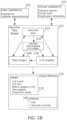
- Figure 1Ais a schematic flowchart of a construction of an overlaid and/or composited display of vascular image and/or other vascular data, according to some embodiments of the present disclosure.
- Figure IDschematically presents a simplified correspondence model used in the construction, according to some embodiments of the present disclosure.
- a data displaycomprises a display of vascular parameter data within a coordinate frame determined by a base 2-D vascular image.
- the display of vascular parameter datais overlaid on the 2-D vascular image.
- a data displaycomprises a display composited (e.g., by use of arithmetic image operations and/or color and/or transparency channel recoding of images) from a plurality of 2-D vascular images, transformed to the coordinate frame of the base 2-D vascular image.
- the base 2-D vascular imagewhich provides the coordinate frame, comprises image data obtained, for example, by X-ray angiography, and/or from angiographic computed tomography (CT), magnetic resonance imaging (MRI), positron emission tomography (PET), optical coherence tomography (OCT), and/or intravascular ultrasound (IVUS).
- vascular parameter dataoptionally comprises, for example, values of vascular width, curvature, digital FFR, blood pressure, and/or another parameter.
- parameter valuesare continuously or sparsely specified along the length of vascular segments, and/or specified as values pertaining to particular vascular segment lengths.
- the vascular parameter datais matched to display coordinates taken from the 2-D vascular image via a correspondence model.
- the correspondence modelcomprises links between data in different images and/or data modalities, by specifying which data associated with the same anatomical location are indexable to one another.
- dataare associated in such a way that there is no canonical (that is, no single governing) spatial and/or planar location assigned to an anatomical location. Rather, there is optionally different positional information associated with the anatomical information for each of a plurality of different data sets within which the anatomical location is represented. Except for the correspondence relationship established within the model, there is no general requirement that the positional information of one data set should be consistent in space with the positional information in any other data set.
- FIG. 1An example model 50 ( Figure ID) is now described as a schematic example of correspondence, and/or of its potential advantages.
- a model that optionally comprises additional featuresis described, for example, in relation to Figure 2B .
- the image data related to each other by the model 50comprise at least a first angiographic image 52 and a second angiographic image 54.
- centerline positions along blood vessel images 51, 53are part of the model 50; defined for each of the images 52, 54.
- vascular centerline positionis used herein for purposes of illustration, and is not limiting.
- use of 2-D image centerline positionhas the potential advantage of being readily calculated from a 2-D image, while compactly identifying locations distributed along a vascular extent.
- the example model 50links each set of centerline positions of blood vessel images 51, 53 (which may be an image pixel coordinate, for example) to one of a plurality of identifiers 56.
- the linkageis such that there are identifiers 56 linked to a centerline position (e.g., positions 51A, 53A) in each of the first angiographic image 52, and the second angiographic image 54.
- careis taken that positions linked to the same identifier also image substantially the same anatomical position. Methods for doing this include, for example, directly identifying homologies between the 2-D images, and/or techniques for back-projecting rays from 2-D images taken from different angles to their region of closest intersection. Such methods have been described, for example, in International Patent Publication No. WO2014/111930 to the Applicant, filed January 15, 2014 , the contents of which are incorporated by reference herein in their entirety.
- identifiers 56can be established in one of several forms.
- identifierscomprise tags and/or indices.
- tags and/or indicesare defined to have some kind of ordered relationship, for example, an ordered relationship based on position along a vascular segment, and/or branch position within a tree of vascular segments.
- identifiersare established as positions along a non-spatial frame of reference. An example of this is a vascular tree organized as branch nodes and distances (optionally, relative distances) along vascular segments joining the nodes.
- identifiersare optionally defined at one or more levels of specification. For example, all data pertaining to a particular vascular segment optionally share an identifier for that segment. Within the segment, data are optionally further identified by one or more position identifiers (e.g. , distance along the segment and/or index into a position-ordered array of sub-segment identifiers).
- homology groupis used to refer to the set of all data which share linkage to a certain identifier, whether it is a high-level identifier (such as a segment identifier), or a low-level identifier (such as a sub-segment position identifier). Those data are said to be members of the same homology group, and/or said to share their anatomical identification. Conversely, herein, a homology group is said to be “in” (or “represented in”) a certain data set (such as an image) if any member or region of the data set is a member of the homology group.
- a modelcan define common anatomical locations for different regions of different images, without requiring a common spatial frame of reference. For example, there is no inherent dominance between the coordinate frames of the first and second angiographic images 52, 54. There is not even a requirement that the coordinate frames of the two images be uniquely localized within a mutual (e.g. , 3-D) frame of reference. In some embodiments, it is potentially infeasible to identify such a coordinate frame. For example, there may be only an approximate consensus available. Reasons for this include the potential for unknown relative errors in determining the positions of all relevant components of the imaging system, movements during imaging, and/or changes in some details of the anatomy itself over time. Any of these could introduce inconsistencies between images in a data set which are difficult to entirely eliminate.
- a data setneed not comprise image data in order to be integrated with model 50.
- Other data 58optionally comprises, for example, non-image data such as values of vascular width, curvature, digital FFR, blood pressure, and/or another parameter, each value being linked to one or more homology groups.
- the other data 58may include a measurement related to the entire vascular structure, such as blood pressure.
- the other data 58is associated with substantially all of the identifiers 56.
- the other data 58may be obtained from intravenous measurements (e.g., FFR, blood pressure, etc.) at specific points in the blood vessels shown in images 51, 53.
- a usermay select the appropriate identifier(s) 56 based on location(s) of the measurement(s).
- measurement toolsmay determine a location of the measurement or provide the measurement in conjunction with an image.
- the other data 58 in these other instancesis assigned to the appropriate identifier 56 based on the identified location provided in the data and/or through image analysis/correlation with model 50 and/or images 52, 54.
- the other data 58may also be determined from the images 52, 54, and/or other images. For example, values of vascular width, curvature, and/or diameter may be determined from the images 52, 54, and/or other images. The locations from where the values are determined are correlated to the model 50 and/or the images 52, 54 and associated with the appropriate identifier(s) 56.
- a correspondence modelis used to achieve this, optionally in real time.
- a method of compositing image and measurement data (for example) for displayis described below. It should be understood that the order of individual operations shown is illustrative, and may be performed in a different order (for example, composition to an image described in relation to block 24 is optionally performed along with the position-mapping operations of block 20), in concerted form (for example, the tests of block 16 and 18 are optionally comprised within the selection of block 14), and/or otherwise suitably rearranged from the order presented herein.
- a base viewis selected.
- the base viewcomprises a visual display coordinate system together with data indexed to that display coordinate system- typically, an image.
- the base viewcomprises an originally acquired 2-D angiographic image 52. At least some coordinates in the base view are linked to the vascular model 50, for example, via identifiers 56.
- one or more compositing data sourcesare selected.
- Compositing data sourcesoptionally correspond to "other data" 58 as described in relation to Figure ID.
- the compositing data sourcescomprise, for example, measurements of vascular parameters such as width, diameter or radius (simulated or actual); FFR (fractional flow resistance)- invasively determined, image- based calculated, and/or simulated; curvature and/or tortuosity; plaque burden and/or calcification; relative flow and/or flow velocity; pressure and/or pressure change; TIMI (thrombolysis in myocardial infarction) grade and/or frame count; simulated stent; perfusion and/or tissue territory information (e.g. , from MIR, CT, PET, and/or SPECT); one or more SYNTAX SCORE sub-scores; and/or vascular deformation information, for example as derived from a cine sequence of angiographic images.
- vascular parameterssuch as width, diameter or radius (simulated or actual); FFR (fractional flow
- compositing data sourcescomprise additional image information.
- a compositing data sourcemay include an image taken before or after the image forming the base references frame. This is of potential benefit, for example, to allow the visualization of changes in vascular collateral structure, changes in vascular width due to disease progression, and/or changes in vascular width as a result of a treatment (such as a stent placement).
- Data in the one or more compositing data sourcesare linked to the vascular model 50 via identifiers 56.
- a first homology groupis selected for processing into a composited view.
- the homology groupis optionally comprised of one or more identifiers from identifiers 56.
- compositing source datais associated to one or more positions in the coordinate system of the base view via links made through the homology group. Details of a method of performing block 20 are described, for example, in relation to Figure IB.
- compositingcomprises conversion of an image of the base view with the mapped data of the compositing source(s).
- the compositingcomprises any method for compositing two images together; for example, opaque and/or transparent overlay, assignment of composited parts to separate color channels, and/or arithmetical operations.
- Figure IBis a schematic flowchart for the conversion of compositing source data to a form displayable as an image together with corresponding image data, according to some embodiments of the present disclosure.
- the operations of Figure IBcomprise sub-operations of block 20 of Figure 1A .
- the flowchart of Figure IBillustrates a single compositing source 44, however, it should be understood that it can be applied to any number of compositing sources.
- the flowchartbegins, and the next index within the currently selected homology group is obtained.
- the indexis to a region along the length of the vascular branch.
- the data sourcecomprises one value for the current homology group, there is only one index.
- an image location (on the base view) linked to the homology group indexis obtained. In some embodiments, this is found by examining links between the homology group associations 40 (optionally corresponding to identifiers 56), and image data locations 42 (optionally corresponding, for example, to centerline positions 51, 53).
- the base viewcan represent any view scale and/or orientation (and in some preferred embodiments, any scale and/or orientation of the coordinate system of an original angiographic image).
- the corresponding compositing source data for the selected homology group indexis obtained. Once again, in some embodiments, this includes examining links between the homology group associations 40 and the compositing source data 44.
- the obtained image location of block 32is assigned to the obtained compositing source data of block 34.
- thiscomprises, for example, assignment in a tabular data structure, placement of one or more pixels in an overlay (immediately and/or just before compositing), and/or construction of a drawing command (e.g., of a stream of drawing commands) or drawing object (e.g. , an XML object of an XML-encoded drawing file).
- the spatially (3-D) distributed regions of a vasculaturehave no fixed position relationship relative to one another in an arbitrarily oriented 2-D angiographic image of the vasculature.
- anatomical regionsmove through time as well, for example, as a function of respiratory and/or cardiac motion, and/or as a function of evolving actual and/or simulated disease state.
- there is a plurality of potential base imageseach having an equivalent relationship to the same compositing source data as far as spatial position is concerned.
- the compositing source dataitself is optionally free of spatial position information, apart from its homology group links.
- compositing source datacan be composited to base views, which themselves are spatially incompatible with one another, since there is optionally no canonical view and/or anatomical state to which they preferably apply.
- FIG. 1Cschematically illustrates a graphical user interface 500 for interacting with an angiographic image, according to some embodiments of the present disclosure.
- the example graphical user interface 500comprises an image display region 500A and optionally a control/indicator region 500B.
- image display region 500Acomprises an angiographic image 503.
- angiographic image 503is presented as and/or together with one or more overlay and/or composited elements, for example, elements described in relation to Figures 3A-3J herein.
- Figure 1Cshows a region tag 325A, a shading- encoded ⁇ e.g., color-encoded) vascular tree 310, and a width encoded vascular tree 335.
- an interface for view selection 501including a mode selection menu 505, which optionally allows choosing a mode for selecting vascular segments and/or vascular segment regions.
- the "tree select" mode interface 508 showndisplays an abstracted model of a vascular tree 523 (connectivity is shown, but other geometry is suppressed).
- view of the left or right coronary artery treeis selectable, for example, by a control such as radio buttons 520.
- segments calculated to have particular clinical significanceare indicated, for example, by callout tags 521, and/or by another indication.
- the view angle of the image 503 shown in image display region 500Ais selected based on segments of interest (e.g., darkened segments 522), which the user indicates ⁇ e.g., by clicking), and/or are selected by default according to which vascular segments appear to have the most clinical significance, e.g., due to a reduced vascular diameter.
- a view angleis automatically selected as a view angle based on the selected segments of interest, and one or more criteria for their optimal display.
- the criteria for optimal displayoptionally comprise, for example, strong contrast along the vascular extent, and/or vascular extent which is the longest in the 2-D frame of reference that the image displays. It is to be understood that other modes of vascular segment selection are optionally provided, for example, from a list (“list select”) and/or from a 3-D view of the vascular tree ("spatial select").
- an overlay option interface 502provides for selection of one or more overlay options.
- Figure 1Cshows selection of an "FFR analysis” mode (fractional flow reserve analysis).
- Figure 1Cshows controls 506 that provide for selection of overlay options.
- Control of the vascular width display 335comprises, for example, a control to show/hide the overlay component, a width magnification control (2x the actual proportional width is shown), and/or to show revascularized width at parts of the vascular tree which are determined by FFR analysis to be significantly stenotic.
- the "FFR" set of controlsincludes switches to turn on or off display of digital FFR (corresponding to shading-encoded tree 310), and/or probe- determined FFR value tags 325A.
- one or more additional overlay option modesare optionally provided; for example: for the display of such parameters as curvature, tortuosity, analysis of plaque positions and/or thickness, analysis of other flow parameters, TIMI grade, tissue perfusion analysis, and/or vascular state scoring such as SYNTAX Score and/or its subscores.
- thesecorrespond, for example, to any of the compositing data sources described in relation to block 12 of Figure 1A .
- Figure 2Ais a block diagram of a system 100 for production and use of a dynamically updatable vascular tree model, according to some exemplary embodiments of the present disclosure.
- Figure 2Bis a block diagram including particular examples by which some of the blocks of Figure 2A are realized, according to some exemplary embodiments of the present disclosure.
- initial image or other data 103is provided to a vascular tree reconstructor 110, after acquisition by one or more imagers or data acquisition (DAQ) systems 120.
- the image datais obtained, for example, by X-ray angiography, and/or from angiographic computed tomography (CT), magnetic resonance imaging (MRI), positron emission tomography (PET), optical coherence tomography (OCT), and/or intravascular ultrasound (IVUS).
- CTangiographic computed tomography
- MRImagnetic resonance imaging
- PETpositron emission tomography
- OCToptical coherence tomography
- IVUSintravascular ultrasound
- the data providedcomprises non-image data related to one or more locations of the vasculature; for example, data acquired from a catheter-mounted sensor and/or radiation source.
- the vascular tree reconstructor 110reconstructs provided data 103 into a vascular tree model 102 of the vasculature.
- the systemis described in relation to imaging of vasculature of a mammalian heart- or more specifically a human heart- including, for example, major arteries of the heart. It is to be understood that the system, changed as necessary, is applicable to the modeling of any other vasculature based on the source of the initial data 103.
- the model 102comprises a plurality of partial and/or complementary representations of the spatial and/or topological (e.g. , vascular tree- branch ordered) relationships inherent in the initial data 103.
- Representational modescomprise the capability to represent, for example:
- a role performed by skeletonized vascular tree 210 in providing a homology mapis provided more generally by any data structure that enables determination of homologies among data regions, and the vascular tree-mapped 2-D images are optionally described as homology-mapped 2-D images 220.
- a data structure that enables determination of homologiescomprises, for example, a structure in which parts of the vascular tree are represented, and these part representations are in turn linked to other structures/data types that correspond to the represented part.
- Vascular tree generationis described, for example, in International Patent Application No. IL2014/050044 filed January 15, 2014 by the Applicant, and/or in International Patent Application No. IL2014/050923 filed October 23, 2014 by the Applicant, the contents of which are included herein by reference in their entirety.
- Partsare optionally defined at a level appropriate to the detail required by further calculations that are to be performed.
- Represented parts of the vascular treecan be, for example, points along the vascular segments (as in a skeletonized tree, a 3-D mesh, or a 3-D volumetric representation), a branched tree structure having nodes and distances (optionally without associated spatial location information), nodes and/or segments as such (with or without further detail such as centerline location), and/or another structure used as a basis for anchoring homology determinations.
- homologyis represented without specific reference to a vascular tree representation as such, so that it comprises a "representational mode" only indirectly.
- homologous data regionsare, in some embodiments, tagged, listed, and/or otherwise associated together, optionally without the tags/listings/associations being themselves in direct relationships reflecting position and/or order.
- homology determinationis independent of the global structure of a vascular tree.
- projection mapping into three dimensionsallows determinations of which segment centerlines "belong" together (according, for instance, to general features of proximity and/or orientation), optionally without first, and/or without directly determining the vascular tree relationships of the homology groups themselves.
- the problems of determining global structure, and of determining which data reflect which part of the global structureare optionally treated separately, or in concert, as appropriate to the metric or metrics which are to be calculated.
- one or more virtual updater modules 101are provided.
- a virtual updater module 101is configured to receive information from vascular model 102, and transform it to create one or more new vascular representations in the mode of one or more of the representational modes of vascular model 102.
- the new representationis passed back to the model and integrated therein- to replace and/or supplement the existing model representation.
- a new modelis created, and/or the transformed vascular model information is passed directly to an output module 103.
- vascular model 102exposes 1-D or 2-D data representations of the vasculature to the virtual updater module 101, additionally or alternatively to exposing 3-D representations of the data.
- a virtual updater module 101comprises (for example) a module configured to perform one or more of the following tasks:
- one or more data updater modules 104are provided.
- a data updater module 104is configured to receive image and/or other data 115 from an imaging means or other DAQ source, and to convert it into a form which can be provided to the vascular model 102.
- Image datais provided, for example, by X-ray angiography, and/or from CT, MRI, PET, OCT, and/or IVUS.
- non-image datais provided, for example, by means of a sensor and/or sensed radiation source advanced through the vasculature on a catheter.
- vascular centerlinesare determined for blood vessels identifiable within each of the provided images. Homologies among vascular centerlines in different images are determined, for example, by a method of spatial back-projection, by identification of similarities of vascular branch topology (for example, in comparison to images already assimilated to the model), and/or by identification of similarities in 2- D image vascular appearances (for example, in comparison to images already assimilated to the model).
- estimation of vascular parametersis performed for the new images, for example, by estimation of vascular lumen diameter, tortuosity, or another parameter.
- non-image datais imported to the vascular tree model.
- position of a catheter along a vascular segmentis known in relation to data acquired by a sensor positioned on the catheter, or by another sensor which detects radiation emitted from a position on the catheter.
- datais optionally mapped into the model, for example, directly as a 1-D graph.
- output modules 130are provided.
- the output modules 130are divided, for purposes of description, into views 135 and indices 140.
- Some embodiments of output modules 130combine functions of each output module type.
- a vascular tree modelis viewable as a 3-D model.
- the 3- D modelis, for example, a 3-D disc model, a 3-D mesh model, and/or any other 3-D representation of the data.
- a 3-D viewcan be constructed, for example, by combination of a 3-D skeleton with corresponding 1-D graphs of vascular width.
- 1-D metric graphs for displayare generated from the 1-D graphs 230 of the vascular tree model.
- a schematic view of a tree graph 240can be generated for display, similar, for example, to the abstracted graph display 508.
- the original images including, for example, angiographic image 503,may be displayed in some embodiments.
- the various views of the representational modes of the vascular tree modelare linked together in the viewing interface, which may include a computer screen or projection device.
- a displayed 3-D modelcan serve as an anchoring metaphor for navigating the vasculature.
- Selection of a segmentfor example, causes a display of associated 1 -D graph information, causes display of highlights for a corresponding segment in a displayed tree graph and/or 2-D image, and/or enables selection for display of one or more 2-D images that comprise representations of the cross-section of the selected vessel.
- an output module 130comprises a calculation of one or more additional metrics from a vascular tree model, and/or a provision of one or more indexes based on vascular tree model metrics.
- a fractional flow reserveis calculated, in some embodiments, by comparison of a representation of an imaged vasculature that is virtually-updated to an astenotic (open) state with a vasculature as originally imaged.
- FFR index calculationis described, for example, in International Patent Application No. II, 2014/050043, filed January 15, 2014 , by the Applicant, the contents of which are included herein by reference in their entirety.
- a vascular scoring algorithmis applied to the model to assess clinical situation and provide assistance in selecting a treatment option.
- Automated vascular scoringis described, for example, in International Patent Application No. II, 2013/050889, filed October 24, 2013 , by the Applicant, the contents of which are included herein by reference in their entirety. In either case, the contents of the model are optionally updated according to the parameters calculated as part of index determination.
- output modules 130 and virtual updaters 101are altered in some embodiments to allow: complete combination of the roles of each in a single module, transfer of functions described in connection with one module to the other module, and/or diversion or sharing of output described as provided from a virtual updater module 101 to the model to an output module 130.
- Figures 3A-3Jprovide non-limiting examples of information that can be presented in a combined display, based, for example, on the models and/or model transiting methods described in Figures 1A-2B .
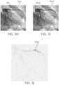
- FIG. 3Aillustrates an angiogram 301 usable as a base image for data presentation, according to some embodiments of the present disclosure.
- Vascular features of the image 301 of particular noteinclude a coronary artery tree 302 including a number of arterial branches 305 (one particular labeled branch 305 is singled out for purposes of description), and two stenotic or potentially stenotic regions 303, 304.
- FIG. 3B-3Dillustrate angiogram vascular overlays for presentation of auxiliary information along portions of vasculature, according to some embodiments of the present disclosure.
- a shading-encoded (color-encoded) vascular tree 310is shown.
- Color codingis according to a cumulative vascular resistance along each vascular branch. In some embodiments, this is encoded to correspond to display of digital FFR (that is, FFR calculated based on features of the image data). For example, lighter shading and/or yellow indicates FFR values close to 1.00, darker shading and/or red indicate lower FFR values, and regions of shading and/or color transition indicate positions along the arteries where stenosis introduces a reduction in digitally calculated FFR.
- Vascular widthis not encoded in Figure 3B , but it is encoded in Figures 3C-3D (for example, in shading-encoded vascular tree 315 of Figure 3C ) by varying the width along the shaded overlay.
- Figure 3Dregions of low FFR transition are suppressed, so that only a partial shaded overlay is shown, appearing at and/or nearby regions where there is a transition in digital FFR.
- FFRis discussed as a parameter for purposes of illustration.
- another value which varies along the vascular extentis shading-encoded for display, for example, one of the parameters described in relation to block 12 of Figure 1A .
- FIG. 3Eillustrate angiogram vascular overlays for presentation of auxiliary information as tags 325A, 325C, according to some embodiments of the present disclosure.
- the vascular tree 325is shown without parameter encoding along its width (although optionally, such encoding may be used in combination with tags 325A, 325C, for example, as show in Figure 1C ).
- tags 325A, 325Cindicate FFR values calculated at specific discrete regions 303, 304.
- the FFR valuesare determined, for example, using a standard pressure probe methodology; for example, a catheter having a pressure sensor is placed upstream and downstream of a stenosis and the pressure ratio converted to an FFR value.
- Callout-style displayis potentially useful, for example, for the display of values that are known only at discrete regions. Additionally or alternatively, callout-style display is provided as a way of indicating numerical values of a parameter at one or more points of interest along the vascular tree.
- vascular overlay 330which visually indicates vascular width corresponding to regions along the vascular image data with which it is displayed. While the image data itself generally also displays vascular width, the overlay provides potential advantages, such as allowing calculated and visual vascular width to be compared, allowing vascular width from one image (for example, from another angle and/or time) to be readily compared to another, and/or to act as a high-contrast display of the original data.
- Another optional feature of a width overlayis shown as vascular tree 335 of Figure 3G .
- display vascular widthis optionally scaled differently than longitudinal vascular extent.
- vascular tree 335shows double-scaled vascular width. A potential advantage of this is to allow easier visual identification of stenotic regions, for example, at regions 303 and/or 304.
- Figures 3H-3Iillustrate angiograms comprising first and second states of a cardiac vasculature, according to some embodiments of the present disclosure.
- Figure 3 Jis a schematic representation of a differential analysis display of the angiograms of Figures 3H-3I , according to some embodiments of the present disclosure.
- a composited display(for example, as shown in Figure 3 J) comprises a combination of two or more vascular images.
- the imagesare raw images (for example, images taken at different times), which have been registered to one another.
- one or more of the imagesis at least partially synthesized.
- the image 301A of Figure 31optionally represents a synthetically revascularized version of the image 301 of Figure 3H .
- An example of a method of synthetic revascularizationis described, for example, in relation to Figures 4A-4B .
- the two or more imagesare subjected to one or more compositing operations.
- compositing operationsoptionally include, for example, addition, subtraction, division, multiplication, transparency overlay, color channel mapping overlay, masking, and/or another image processing technique for combining images.
- compositing operationsare applied, for example, in combination with one or more techniques of filtering, normalization, noise reduction, and/or other image processing techniques.
- region 303A region of difference between two images is illustrated by region 303 (of Figure 3H ), compared to region 303A (of Figure 31). Region 303 is stenotic, while region 303A is not. Figure 3 J has been composited so that differences between the two images are emphasized at region 303C.
- Such a composite displayis potentially useful for isolating changes in a vasculature over time, and/or in two different conditions (for example, with and without the effects of adenosine injection).
- Relevant changes in vasculature over timeoptionally include, for example, changes in vascular width and/or changes in vascular position, for example due to changes in curvature, tortuosity and/or development of vascular collaterals.
- such a composite displayis used to indicate modeled effects of disease treatment and/or progression, for example based on the use of one or more synthetic images.
- FIG. 4A-4Bschematically illustrate a method of modifying an angiogram image to adjust an apparent vascular width shown thereon, according to some embodiments of the present disclosure.
- FIG. 4AShown in Figure 4A is a schematic representation of an identified vascular profile 410, for example one obtained from an image of a blood vessel coursing through a vascular image (such as vascular image 301).
- Vascular profile 400in some embodiments, comprises vascular widths specified along a range of vascular positions 402.
- a synthetic profile 410is generated along a range of vascular positions 412 which are in correspondence with positions 402.
- the synthetic profile 410is wider than the source profile, and optionally represents a revascularization (for example, as obtained after insertion of a stent, or by another treatment).
- synthetic profile 410is narrower, for example to represent effects of a disease progression.
- a copy of the image from which profile 400 was originally obtainedis modified to reflect features of synthetic profile 410.
- the modificationis performed by stretching or shrinking pixel value profiles along profiles such as profile 420.
- Figure 4Ban example of profile stretching is shown. Position along the profile is shown on the horizontal axis, and relative pixel value is shown on the vertical axis. At position 430A, there is no difference between the stretched and unstretched profiles. Moving outward to profile positions 430B, 430C, and 430D, pixel values are increasingly displaced (with interpolation between them) to simulate a wider vascular profile.
- the stretching factoris returned to zero.
- another synthetic vascular width adjustment methodis used, for example, based on the assumption of a circular (typically, but not only) profile and the application of densitometry principles to more accurately simulate changes in the radiopacity profile as a result of vascular width changes.
- a potential advantage of synthetic vascular angiography imagesis their optional use as direct inputs to algorithms which are applicable to raw vascular images. Another potential advantage is to allow more direct visual assessment of anticipated changes as a result of disease treatment or progression to actual changes. For example, comparison of a partially synthetic angiographic image of a condition to an image of the actual condition is potentially useful to a clinician used to seeing and evaluating patient status based on original image data.
- the inventionmay provide a method for displaying vascular parameter data, the method comprising: receiving, in a processor, at least a first and a second 2-D angiographic image each comprising (i) respective 2-D frames of reference, and (ii) vascular image contents viewed from angles at least 300 different from each other; creating, via the processor, a model including a data structure configured to link a plurality of 2-D locations in each of the first and the second 2-D angiographic images; forming, via the processor, an image in the frame of reference of the first 2-D angiographic image; determining, via the processor, the vascular parameter data for the linked plurality of 2-D locations using the second 2-D angiographic image; and displaying via the processor, the vascular parameter data at the plurality of linked 2-D locations in the frame of reference of the first image.
- the display away from the linked 2-D locationsmaybe based on the first image.
- the linkingmay include storing the plurality of 2-D locations in association with an identifying tag.
- the linkingmay include storing the plurality of 2-D locations in association within a list.
- the listis an ordered list.
- the linkingmay include a position specified relative to other locations or elements of the ordered list.
- the display of the vascular parameter data at the plurality of linked 2-D locationsmay include rendering a path between some of the linked 2-D locations, the path being rendered with widths based on values derived from the processing of vascular widths in the correspondingly linked 2-D locations of the second 2-D angiographic image.
- the widthmay be rendered to at least 1. 5x greater scale than the scale of the vascular diameter in the frame of reference of the first 2-D angiographic image.
- the display of the vascular parameter data at the linked 2-D locationsmay include rendering a path between linked 2-D locations, the path having a color assigned based on values of the vascular parameter data.
- the display of the vascular parameter data at the linked 2-D locationsmay include rendering a path between linked 2-D locations, the path having at least one of a transparency or a gap assigned based on values of the vascular parameter data.
- the display of the vascular parameter data at each of the linked 2-D locationsmaybe based on a plurality of accessed parameter data elements.
- the data structuremay link at least a third 2-D angiographic image not registrable to consistently align with the first and second 2- D angiographic images by an invertible 2-D geometrical transform, and at least some values of the accessed vascular parameter data elements are derived from processing of the correspondingly linked 2-D locations of the third image.
- the display of the vascular parameter data at the plurality of linked 2-D locationsmay include rendering using any combination of displayed path width, display color, display transparency, or display color channel assignment.
- the plurality of accessed parameter data elementsmay represent a same vascular parameter for a plurality of parameter values.
- the plurality of parameter valuesmay include values representing a vasculature in different states.
- the display of the vascular parameter data at each of the linked 2-D locationsmay alternate between being based on different element accessed vascular parameter data.
- image contents of at least one of the first and the second 2-D angiographic imagesmay include views of a vasculature recorded at different view angles.
- image contents of at least one of the first and the second 2-D angiographic imagesmay include views of a vasculature in at least two respective different anatomical states.
- the inventionprovides a system for preparing vascular parameter data for display comprising: a processor configured to traverse a linkage model stored in digital memory, the linkage model comprising: at least a first and a second 2-D angiographic image representing respectively at least two separate viewing angles of a cardiac vasculature, and a data structure linking corresponding 2-D locations of the 2-D angiographic images, the corresponding 2-D locations including representation in common of a region of the cardiac vasculature; wherein the processor is furthermore configured to form for display a display image in the frame of reference of the first image; wherein the display image at the plurality of linked 2-D locations in the frame of reference of the first image is based on at least vascular parameter data accessed by use of the linking data structure; and wherein the accessed vascular parameter data is derived from processing of the correspondingly linked 2-D locations of the second image.
- the display image away from the linked 2-D locationsmay be based on the first image.
- the linkingmay comprise association in common to an identifying tag.
- the linkingmay comprise association in common within a list.
- compositions, method or structuremay include additional ingredients, steps and/or parts, but only if the additional ingredients, steps and/or parts do not materially alter the basic and novel characteristics of the claimed composition, method or structure.
- a compoundor “at least one compound” may include a plurality of compounds, including mixtures thereof.
- treatingincludes abrogating, substantially inhibiting, slowing or reversing the progression of a condition, substantially ameliorating clinical or aesthetical symptoms of a condition or substantially preventing the appearance of clinical or aesthetical symptoms of a condition.
- range formatmerely for convenience and brevity and should not be construed as an inflexible limitation on the scope of the systems, methods, and/or computer program products. Accordingly, the description of a range should be considered to have specifically disclosed all the possible subranges as well as individual numerical values within that range. For example, description of a range such as “from 1 to 6" should be considered to have specifically disclosed subranges such as “from 1 to 3", “from 1 to 4", “from 1 to 5", “from 2 to 4", “from 2 to 6", “from 3 to 6", etc. ; as well as individual numbers within that range, for example, 1, 2, 3, 4, 5, and 6. This applies regardless of the breadth of the range.
Landscapes
- Health & Medical Sciences (AREA)
- Life Sciences & Earth Sciences (AREA)
- Engineering & Computer Science (AREA)
- Medical Informatics (AREA)
- Public Health (AREA)
- General Health & Medical Sciences (AREA)
- Biomedical Technology (AREA)
- Surgery (AREA)
- Pathology (AREA)
- Veterinary Medicine (AREA)
- Heart & Thoracic Surgery (AREA)
- Molecular Biology (AREA)
- Animal Behavior & Ethology (AREA)
- Physics & Mathematics (AREA)
- Biophysics (AREA)
- Nuclear Medicine, Radiotherapy & Molecular Imaging (AREA)
- Radiology & Medical Imaging (AREA)
- Cardiology (AREA)
- Physiology (AREA)
- High Energy & Nuclear Physics (AREA)
- Optics & Photonics (AREA)
- Vascular Medicine (AREA)
- Oral & Maxillofacial Surgery (AREA)
- Dentistry (AREA)
- Primary Health Care (AREA)
- Epidemiology (AREA)
- Hematology (AREA)
- Human Computer Interaction (AREA)
- Data Mining & Analysis (AREA)
- Databases & Information Systems (AREA)
- Computer Vision & Pattern Recognition (AREA)
- Robotics (AREA)
- General Engineering & Computer Science (AREA)
- Computer Graphics (AREA)
- Theoretical Computer Science (AREA)
- Quality & Reliability (AREA)
- General Physics & Mathematics (AREA)
- Pulmonology (AREA)
- Apparatus For Radiation Diagnosis (AREA)
- Processing Or Creating Images (AREA)
Abstract
Description
- The present disclosure relates to the field of medical image analysis, and more particularly, to the presentation of medical images of a vasculature.
- Arterial stenosis is one of the most serious forms of arterial disease. In clinical practice, stenosis severity is estimated by using either simple geometrical parameters, such as determining the percent diameter of a stenosis, or by measuring hemodynamically based parameters, such as the pressure -based myocardial Fractional Flow Reserve (FFR). FFR is an invasive measurement of the functional significance of coronary stenoses. The FFR measurement represents a ratio between maximal blood flow in an area of stenosis and maximal blood flow in the same area without the stenosis. Earlier studies have shown that lesions with an FFR that is less than 0.75 provide an accurate predictor of ischemia; and that deferral of percutaneous coronary intervention for lesions with FFR > 0.75 appeared to be safe.
- Modeling vascular flow to assess vascular flow is described, for example, in
U.S. published patent application number 2012/0059246 of Taylor , to a "Method And System For Patient-Specific Modeling Of Blood Flow", which describes embodiments which include a system for determining cardiovascular information for a patient. The system may include at least one computer system configured to receive patient- specific data regarding a geometry of at least a portion of an anatomical structure of the patient. The portion of the anatomical structure may include at least a portion of the patient's aorta and at least a portion of a plurality of coronary arteries emanating from the portion of the aorta. The at least one computer system may also be configured to create a three- dimensional model representing the portion of the anatomical structure based on the patient- specific data, create a physics-based model relating to a blood flow characteristic within the portion of the anatomical structure, and determine a fractional flow reserve within the portion of the anatomical structure based on the three-dimensional model and the physics-based model. - Additional background art includes:
U.S. Patent No. 8,548,778 of Taylor . - Further background art includes
U.S. Patent Publication No. 2015/0342551 to Lavi et al ; International Patent Publication No.WO2015/059706 to Lavi et al ;U. S. Patent Publication No. 2015/0335304 to Ifat Lavi et al ;U.S. Patent Publication No. 2015/0339847 to Benlshti et al ; andU.S. Patent Publication No. 2015/0265162 to Lavi et al. ; the contents of which are hereby incorporated herein by reference. - There is provided, in accordance with some exemplary embodiments, a method of preparing vascular parameter data for display. The example method includes receiving at least a first and a second 2-D angiographic image each comprising respective 2-D frames of reference and vascular image contents viewed from angles at least 30° different from each other. The example method also includes creating a model including a data structure configured to link a plurality of 2-D locations in each of the first and the second 2-D angiographic images and forming an image in the frame of reference of the first 2-D angiographic image. The example method further includes determining the vascular parameter data for the linked plurality of 2-D locations using the second 2-D angiographic image and displaying the vascular parameter data at the plurality of linked 2-D locations in the frame of reference of the first image.
- According to some embodiments, display away from the linked 2-D locations is based on the first image.
- According to some embodiments, the linking comprises association in common to an identifying tag.
- According to some embodiments, the linking comprises association in common within a list.
- According to some embodiments, the list is an ordered list.
- According to some embodiments, the association in common is defined as position specified relative to other locations or elements of the ordered list.
- According to some embodiments, display at the plurality of linked 2-D locations comprises a path rendered between some of the linked 2-D locations; the path being rendered to widths based on values derived from the processing of vascular widths in the correspondingly linked 2-D locations of the second image.
- According to some embodiments, the width is rendered to at least 1.5x greater scale than the scale of the vascular diameter in the frame of reference of the first image.
- According to some embodiments, display at the linked 2-D locations comprises a path rendered between linked 2-D locations, the path having a color assigned based on values of the accessed vascular parameter data.
- According to some embodiments, display at the linked 2-D locations comprises a path rendered between linked 2-D locations, the path having at least one of a transparency or a gap assigned based on values of the accessed vascular parameter data.
- According to some embodiments, display at each of the linked 2-D locations is based on a plurality of accessed parameter data elements.
- According to some embodiments, the data structure links at least a third 2-D angiographic image not registrable to consistently align with the first and second images by an invertible 2-D geometrical transform, and at least some values of the accessed vascular parameter data elements are derived from processing of the correspondingly linked 2-D locations of the third image.
- According to some embodiments, the display at the plurality of linked 2-D locations comprises display using any combination of displayed path width, display color, display transparency, or display color channel assignment.
- According to some embodiments, the plurality of accessed parameter data elements represent the same vascular parameter for a plurality of parameter values.
- According to some embodiments, the plurality of parameter values comprise values representing the vasculature in different states.
- According to some embodiments, display at each of the linked 2-D locations alternates between being based on different element accessed vascular parameter data.
- According to some embodiments, the image contents of at least the first and second images comprise views of a vasculature taken from different view angles.
- According to some embodiments, the image contents of at least the first and second images comprise views of a vasculature in at least two respective different anatomical states. There is provided, in accordance with some exemplary embodiments, a system for preparing vascular parameter data for display comprising: a processor configured to traverse a linkage model stored in digital memory, the linkage model comprising: at least a first and a second 2-D angiographic image representing respectively at least two separate viewing angles of a cardiac vasculature, and a data structure linking corresponding 2-D locations of the 2-D angiographic images, the corresponding comprising representation in common of a region of the cardiac vasculature; wherein the processor is furthermore configured to form for display a display image in the frame of reference of the first image; and wherein the display image at the plurality of linked 2-D locations in the frame of reference of the first image is based on at least vascular parameter data accessed by use of the linking data structure; and wherein the accessed vascular parameter data is derived from processing of the correspondingly linked 2-D locations of the second image.
- According to some embodiments, the display image away from the linked 2-D locations is based on the first image.
- According to some embodiments, the linking comprises association in common to an identifying tag.
- According to some embodiments, the linking comprises association in common within a list.
- Unless otherwise defined, all technical and/or scientific terms used herein have the same meaning as commonly understood by one of ordinary skill in the art to which the disclosure pertains. Although systems, methods, and/or computer program products similar or equivalent to those described herein can be used in the practice or testing of embodiments disclosed herein, exemplary systems, methods, and/or computer program products are described below. In case of conflict, the patent specification, including definitions, will control. In addition, the systems, methods, computer program products, and examples are illustrative only and are not intended to be necessarily limiting.
- As will be appreciated by one skilled in the art, aspects of the present disclosure may be embodied as a system, method, or computer program product. Accordingly, aspects of the present disclosure may take the form of an entirely hardware embodiment, an entirely software embodiment (including firmware, resident software, micro-code, etc.), or an embodiment combining software and hardware aspects that may all generally be referred to herein as a "circuit," "module" or "system." Furthermore, some embodiments of the present disclosure may take the form of a computer program product embodied in one or more computer readable medium(s) having computer readable program code embodied thereon. Implementation of the method and/or system of some embodiments disclosed herein can involve performing and/or completing selected tasks manually, automatically, or a combination thereof. Moreover, according to actual instrumentation and equipment of some embodiments of the method and/or system disclosed herein, several selected tasks could be implemented by hardware, by software or by firmware and/or by a combination thereof, e.g., using an operating system.
- For example, hardware for performing selected tasks according to some embodiments of the disclosure could be implemented as a chip or a circuit. As software, selected tasks according to some embodiments of the disclosure could be implemented as a plurality of software instructions executed by a computer using any suitable operating system. In an exemplary embodiment of the disclosure, one or more tasks, according to some exemplary embodiments of a method and/or a system as described herein, are performed by a data processor, such as a computing platform for executing a plurality of instructions. Optionally, the data processor includes a volatile memory for storing instructions and/or data and/or a nonvolatile storage, for example, a magnetic hard-disk and/or removable media, for storing instructions and/or data. Optionally, a network connection may be provided. A display and/or a user input device such as a keyboard or mouse may also be provided.
- Any combination of one or more computer readable medium(s) may be utilized for some embodiments of the disclosure. The computer readable medium may be a computer readable signal medium or a computer readable storage medium. A computer readable storage medium may be, for example, but not limited to, an electronic, magnetic, optical, electromagnetic, infrared, or semiconductor system, apparatus, or device, or any suitable combination of the foregoing. More specific examples (a non- exhaustive list) of the computer readable storage medium would include the following: an electrical connection having one or more wires, a portable computer diskette, a hard disk, a random access memory (RAM), a read-only memory (ROM), an erasable programmable read-only memory (EPROM or Flash memory), an optical fiber, a portable compact disc read-only memory (CD-ROM), an optical storage device, a magnetic storage device, or any suitable combination of the foregoing. In the context of this document, a computer readable storage medium may be any tangible medium that can contain, or store a program for use by or in connection with an instruction execution system, apparatus, or device.
- A computer readable signal medium may include a propagated data signal with computer readable program code embodied therein, for example, in baseband or as part of a carrier wave. Such a propagated signal may take any of a variety of forms, including, but not limited to, electro-magnetic, optical, or any suitable combination thereof. A computer readable signal medium may be any computer readable medium that is not a computer readable storage medium and that can communicate, propagate, or transport a program for use by or in connection with an instruction execution system, apparatus, or device.
- Program code embodied on a computer readable medium and/or data used thereby may be transmitted using any appropriate medium, including but not limited to wireless, wireline, optical fiber cable, RF, etc., or any suitable combination of the foregoing.
- Computer program code for carrying out operations for some embodiments of the present disclosure may be written in any combination of one or more programming languages, including an object oriented programming language such as Java, Smalltalk, C++ or the like and conventional procedural programming languages, such as the "C" programming language or similar programming languages. The program code may execute entirely on the user's computer, partly on the user's computer, as a stand-alone software package, partly on the user's computer and partly on a remote computer or entirely on the remote computer or server. In the latter scenario, the remote computer may be connected to the user's computer through any type of network, including a local area network (LAN) or a wide area network (WAN), or the connection may be made to an external computer (for example, through the Internet using an Internet Service Provider).
- Some embodiments of the present disclosure may be described below with reference to flowchart illustrations and/or block diagrams of methods, apparatus (systems) and computer program products according to embodiments of the disclosure. It will be understood that each block of the flowchart illustrations and/or block diagrams, and combinations of blocks in the flowchart illustrations and/or block diagrams, can be implemented by computer program instructions. These computer program instructions may be provided to a processor of a general purpose computer, special purpose computer, or other programmable data processing apparatus to produce a machine, such that the instructions, which execute via the processor of the computer or other programmable data processing apparatus, create means for implementing the functions/acts specified in the flowchart and/or block diagram block or blocks.
- These computer program instructions may also be stored in a computer readable medium that can direct a computer, other programmable data processing apparatus, or other devices to function in a particular manner, such that the instructions stored in the computer readable medium produce an article of manufacture including instructions which implement the function/act specified in the flowchart and/or block diagram block or blocks.
- The computer program instructions may also be loaded onto a computer, other programmable data processing apparatus, or other devices to cause a series of operational steps to be performed on the computer, other programmable apparatus or other devices to produce a computer implemented process such that the instructions which execute on the computer or other programmable apparatus provide processes for implementing the functions/acts specified in the flowchart and/or block diagram block or blocks.
- Additional features and advantages of the disclosed system, method, and apparatus are described in, and will be apparent from, the following Detailed Description and the Figures.
- Some embodiments of the example systems, methods, and/or computer program products are herein described, by way of example only, with reference to the accompanying drawings. With specific reference now to the drawings in detail, it is stressed that the particulars shown are by way of example, and for purposes of illustrative discussion of embodiments disclosed herein. In this regard, the description taken with the drawings makes apparent to those skilled in the art how embodiments of the disclosure may be practiced.
- In the drawings:
FIG. 1A is a schematic flowchart providing for a construction of an overlaid and/or composited display of vascular image and/or other vascular data, according to some embodiments of the present disclosure;- FIG. IB is a schematic flowchart for the conversion of compositing source data to a form displayable as an image together with corresponding image data, according to some embodiments of the present disclosure;
FIG. 1C schematically illustrates a graphical user interface according to some embodiments of the present disclosure;- FIG. ID schematically presents a simplified correspondence model used in the construction, according to some embodiments of the present disclosure;
FIG. 2A is a block diagram of a system for production and use of a dynamically updatable vascular tree model, according to some exemplary embodiments of the present disclosure;FIG. 2B is a block diagram including particular examples by which some of the blocks ofFigure 2A are realized, according to some exemplary embodiments of the present disclosure;FIG. 3A illustrates an angiogram usable as a base image for data presentation, according to some embodiments of the present disclosure;FIGs. 3B, 3C and3D illustrate angiogram vascular overlays for presentation of auxiliary information along extent of vasculature, according to some embodiments of the present disclosure;FIG. 3E illustrates angiogram vascular overlays for presentation of auxiliary information as tags, according to some embodiments of the present disclosure;FIGs. 3F and 3G illustrate angiogram vascular overlays for presentation of width information, according to some embodiments of the present disclosure;FIGs. 3H and 31 illustrate angiograms comprising first and second states of a cardiac vasculature, according to some embodiments of the present disclosure;FIG. 3J is a schematic representation of a differential analysis display of the angiograms ofFigures 3H-3I , according to some embodiments of the present disclosure; andFIGs. 4 A and 4B schematically illustrate a method of modifying an angiogram image to adjust an apparent vascular width shown thereon, according to some embodiments of the present disclosure.- The present disclosure, in some embodiments thereof, relates to the field of medical image analysis, and more particularly, to the presentation of medical images of a vasculature.
- An aspect of some embodiments of the current disclosure relates to the compositing together of model-linked vascular data from a plurality of sources, including, for example, at least one 2-D angiography image, for display in the frame of reference of the at least one angiography image.
- In some embodiments, model linking of vascular data comprises a plurality of 2- D angiographic images, along with additional vascular parameter data. Optionally, at least some of the additional vascular parameter data is derived from analysis of the 2-D angiographic images. Additionally or alternatively, at least some of the additional vascular parameter data is derived from another source; for example, another imaging modality, and/or another sensing modality such as sensing from a catheter probe. In some embodiments, the 2-D angiographic images are taken from significantly different view angles (for example, from view angles different by at least 15°, 30°, 45°, 60°, 90°, 135°, or 180°). The different view angles potentially interfere with direct registration of the images based on correlations among their visual features. This is potentially of particular relevance for a vasculature such as the coronary vasculature, in which a single 2-D image compresses depth information around the curvature of the heart. In some embodiments, the 2-D angiographic images comprise images taken of a vascular anatomy in different states- for example, different states of disease progression and/or treatment- and/or at different times, between which the anatomical structure of the vascular has changed. In some embodiments, the model comprises a data structure linking corresponding regions of 2-D angiographic images and/or corresponding elements of non-image vascular parameter data. The linkage is made between data samples which represent in common a region of the cardiac vasculature. For example, linkage is between data samples which represent features and/or characteristics of a particular part of a particular vascular segment. In some embodiments, parameter data which is sparsely available for the imaged vasculature is linked to a particular segment or other vascular domain that encompasses a plurality of linkage regions.
- Optionally, the linkage regions defined are fully isomorphic with anatomy (e.g., linkage is based on representation of the same vascular tissue). This is a potential advantage when images in a model are of the same vasculature acquired at substantially the same time (e.g., without anatomical remodeling between their times of acquisition). Optionally or additionally, the linking region is relative to some other definition; for example, a region of a vasculature that is 10% of a total distance between two vascular branch points. This is potentially advantageous when linking between images which represent different anatomical states (for example, images taken during the course of a disease which comprises changes in vascular shapes, plaque development, or other anatomical changes). In the memory of a computerized implementation of the example model, linkage optionally has one of several forms; for example; common reference to an identifier or other token, common relative and/or absolute position within a data structure (optionally corresponding, for example, to relative distance along a vascular centerline), and/or common presence (optionally, presence by reference) in a row, column, or other compartment of a data structure.
- In a 2-D image, optionally, only a portion of the image regions is linked into the linkage model. For example, in some embodiments, only vascular regions are linked to the linkage model. In some embodiments, vascular centerlines are linked to the linkage model. Optionally, non-linked elements in an image are connected to the linked model indirectly through their relationship (e.g. , their relationship in the coordinate system of the 2-D image) to elements that are so-linked.
- In some embodiments of the disclosure provided herein, creation of a composited image for display comprises traversing the model between two or more data sources (e.g. , two or more images, an image and model-mapped non-image data, or another combination), based on their common linkage. It should be understood that in some embodiments, the linkage is not itself inherently geometrical and/or spatial in nature. For example, the linkage is optionally not biject (one-to-one between linked elements), and optionally comprises a linkage to a data set, which is not itself geometrically specified. Optionally, however, the linkages themselves are associated with information that is topographical (e.g. , reflects anatomical connectivity) and/or is ordered (e.g. , there is an ordering of links in a list, such as an order corresponding to relative position along a longitudinal extent of a vascular segment).
- In some embodiments, individual 2-D images comprise at least a 2-D frame of reference. Optionally, the 2-D frame of reference is also associated with a 3-D frame of reference, for example, an image plane, a bounding box, a set of rays in 3-D space that intersect the image plane, or another 3-D plane of reference. Pixels or other elements (e.g. vascular centerlines) of or derived from the 2-D images optionally are assigned coordinates in the 2-D frame of reference. Optionally, the traversal of the model allows non-image data and/or other-image data to be "imported" to the 2-D coordinate system according to its linkage in the model to a region of the 2-D image that has such assigned coordinates. At least insofar as linkages are optionally not biject or between geometrically specified data sets, the importing transformation optionally does not comprise a geometrical transformation as such. In some embodiments, the individual 2- D images are sufficiently different from each other (for example, due to difference in view angle and/or changes in imaged anatomy which produce a different 3-D conformation of the vasculature) such that no invertible geometrical transform, also in two dimensions, can register them to each other. In some embodiments, a difference in view angle between at least one pair of vascular images having contents linked by the model is at least 15°, 30°, 45°, or another larger, smaller, or intermediate angle.
- In some embodiments, a composited image comprises an image for computer-mediated display, which is based on at least a portion of a 2-D angiographic image and some other data from a source that is not originally and/or natively in the frame of reference of the 2-D angiographic image. In some embodiments, the composited image comprises a base image with one or more overlays (for example, overlays in a z-order, which may be understood as extending between a "top" and a "bottom" of a stack of layers, where each layer at least partially obscures underlying layers at regions where the upper layer is populated by display data). Optionally, overlays are at least partially transparent. In some embodiments, a composited image comprises images which are combined into a single layer, for example by use of image algebraic operations including but not limited to addition, subtraction, multiplication and/or division. Optionally, compositing comprises normalization and/or filtering of one or more composited images. Optionally, compositing comprises assignment of different display channels (e.g. , color channels) to different data sources and/or different combinations thereof. Optionally, composited images are adjustable to show or hide different elements; e.g. , by operation by a user of a user interface. In some embodiments, display of composited image elements is separated in time. For example, two composited layers are shown alternately, which potentially is useful for purposes of layer comparison.
- Before explaining at least one embodiment of the disclosure in detail, it is to be understood that the example systems, methods, and/or computer program products provided herein are not necessarily limited in its application to the details of construction and the arrangement of the components and/or methods set forth in the following description and/or illustrated in the drawings. The example systems, methods, and/or computer program products are capable of embodying other embodiments or of being practiced or carried out in various ways.
- Reference is now made to
Figure 1A , which is a schematic flowchart of a construction of an overlaid and/or composited display of vascular image and/or other vascular data, according to some embodiments of the present disclosure. Reference is also made to Figure ID, which schematically presents a simplified correspondence model used in the construction, according to some embodiments of the present disclosure. - In some embodiments, a data display comprises a display of vascular parameter data within a coordinate frame determined by a base 2-D vascular image. Optionally, the display of vascular parameter data is overlaid on the 2-D vascular image. Additionally or alternatively, in some embodiments, a data display comprises a display composited (e.g., by use of arithmetic image operations and/or color and/or transparency channel recoding of images) from a plurality of 2-D vascular images, transformed to the coordinate frame of the base 2-D vascular image.
- In some embodiments, the base 2-D vascular image, which provides the coordinate frame, comprises image data obtained, for example, by X-ray angiography, and/or from angiographic computed tomography (CT), magnetic resonance imaging (MRI), positron emission tomography (PET), optical coherence tomography (OCT), and/or intravascular ultrasound (IVUS). Vascular parameter data optionally comprises, for example, values of vascular width, curvature, digital FFR, blood pressure, and/or another parameter. Optionally, parameter values are continuously or sparsely specified along the length of vascular segments, and/or specified as values pertaining to particular vascular segment lengths.
- In some embodiments, the vascular parameter data is matched to display coordinates taken from the 2-D vascular image via a correspondence model. The correspondence model comprises links between data in different images and/or data modalities, by specifying which data associated with the same anatomical location are indexable to one another. Optionally, data are associated in such a way that there is no canonical (that is, no single governing) spatial and/or planar location assigned to an anatomical location. Rather, there is optionally different positional information associated with the anatomical information for each of a plurality of different data sets within which the anatomical location is represented. Except for the correspondence relationship established within the model, there is no general requirement that the positional information of one data set should be consistent in space with the positional information in any other data set.
- An example model 50 (Figure ID) is now described as a schematic example of correspondence, and/or of its potential advantages. A model that optionally comprises additional features is described, for example, in relation to
Figure 2B . The image data related to each other by themodel 50 comprise at least a firstangiographic image 52 and a secondangiographic image 54. In some embodiments, centerline positions alongblood vessel images 51, 53 (arranged, for example, as arrays or as another collection structure) are part of themodel 50; defined for each of theimages - The
example model 50 links each set of centerline positions ofblood vessel images 51, 53 (which may be an image pixel coordinate, for example) to one of a plurality ofidentifiers 56. The linkage is such that there areidentifiers 56 linked to a centerline position (e.g., positions 51A, 53A) in each of the firstangiographic image 52, and the secondangiographic image 54. Moreover, when the position-to-identifier linkages are established, care is taken that positions linked to the same identifier also image substantially the same anatomical position. Methods for doing this include, for example, directly identifying homologies between the 2-D images, and/or techniques for back-projecting rays from 2-D images taken from different angles to their region of closest intersection. Such methods have been described, for example, in International Patent Publication No.WO2014/111930 to the Applicant, filed January 15, 2014 , the contents of which are incorporated by reference herein in their entirety. - For vascular targets in particular, such techniques permit identification of substantially identical anatomical positions in 2-D images even though they may be very different in the views they capture. It should be understood that the
identifiers 56 can be established in one of several forms. In some embodiments identifiers comprise tags and/or indices. Optionally, tags and/or indices are defined to have some kind of ordered relationship, for example, an ordered relationship based on position along a vascular segment, and/or branch position within a tree of vascular segments. In some embodiments, identifiers are established as positions along a non-spatial frame of reference. An example of this is a vascular tree organized as branch nodes and distances (optionally, relative distances) along vascular segments joining the nodes. - Moreover, identifiers are optionally defined at one or more levels of specification. For example, all data pertaining to a particular vascular segment optionally share an identifier for that segment. Within the segment, data are optionally further identified by one or more position identifiers (e.g. , distance along the segment and/or index into a position-ordered array of sub-segment identifiers).
- Herein, the term "homology group" is used to refer to the set of all data which share linkage to a certain identifier, whether it is a high-level identifier (such as a segment identifier), or a low-level identifier (such as a sub-segment position identifier). Those data are said to be members of the same homology group, and/or said to share their anatomical identification. Conversely, herein, a homology group is said to be "in" (or "represented in") a certain data set (such as an image) if any member or region of the data set is a member of the homology group.
- From the foregoing, it may be understood how a model can define common anatomical locations for different regions of different images, without requiring a common spatial frame of reference. For example, there is no inherent dominance between the coordinate frames of the first and second
angiographic images - It is noted, moreover, that a data set need not comprise image data in order to be integrated with
model 50. Other data 58 optionally comprises, for example, non-image data such as values of vascular width, curvature, digital FFR, blood pressure, and/or another parameter, each value being linked to one or more homology groups. In some examples, the other data 58 may include a measurement related to the entire vascular structure, such as blood pressure. In these examples, the other data 58 is associated with substantially all of theidentifiers 56. In other examples, the other data 58 may be obtained from intravenous measurements (e.g., FFR, blood pressure, etc.) at specific points in the blood vessels shown inimages appropriate identifier 56 based on the identified location provided in the data and/or through image analysis/correlation withmodel 50 and/orimages images images model 50 and/or theimages - Lack of dependency on a unique spatial frame of reference is a potential advantage for the modeling of cardiac vasculature in particular, where heartbeat and respiratory movement is continuous. It can also be a potential advantage for the representation of disease progression in which anatomical details (e.g. sizes, spatial positions, tortuosities, and/or degrees of occlusion) can change over time so that no single spatial representation can include all available data. Moreover, vascular images are often captured under conditions of limited signal-to-noise, and may be prone to other imperfections. Interpretation can depend on subtleties of shape or intensity which might be lost or distorted upon transforming an image into a new frame of reference. Thus, it is a potential advantage for a vascular model to be well-integrated with the presentation of original image data, which some embodiments of correspondence-based modeling allow.
- Nevertheless, it is also a potential advantage to be able to rapidly prepare results from a plurality of data sources having disparate positional definitions for viewing within a common frame of reference. In some embodiments, a correspondence model is used to achieve this, optionally in real time.
- A method of compositing image and measurement data (for example) for display is described below. It should be understood that the order of individual operations shown is illustrative, and may be performed in a different order (for example, composition to an image described in relation to block 24 is optionally performed along with the position-mapping operations of block 20), in concerted form (for example, the tests of
block - At
block 10, in some embodiments, a base view is selected. The base view comprises a visual display coordinate system together with data indexed to that display coordinate system- typically, an image. In some embodiments, the base view comprises an originally acquired 2-Dangiographic image 52. At least some coordinates in the base view are linked to thevascular model 50, for example, viaidentifiers 56. - At
block 12, in some embodiments, one or more compositing data sources are selected. Compositing data sources optionally correspond to "other data" 58 as described in relation to Figure ID. The compositing data sources comprise, for example, measurements of vascular parameters such as width, diameter or radius (simulated or actual); FFR (fractional flow resistance)- invasively determined, image- based calculated, and/or simulated; curvature and/or tortuosity; plaque burden and/or calcification; relative flow and/or flow velocity; pressure and/or pressure change; TIMI (thrombolysis in myocardial infarction) grade and/or frame count; simulated stent; perfusion and/or tissue territory information (e.g. , from MIR, CT, PET, and/or SPECT); one or more SYNTAX SCORE sub-scores; and/or vascular deformation information, for example as derived from a cine sequence of angiographic images. - In some embodiments, compositing data sources comprise additional image information. For example, a compositing data source may include an image taken before or after the image forming the base references frame. This is of potential benefit, for example, to allow the visualization of changes in vascular collateral structure, changes in vascular width due to disease progression, and/or changes in vascular width as a result of a treatment (such as a stent placement).
- Data in the one or more compositing data sources are linked to the
vascular model 50 viaidentifiers 56. - At
block 14, in some embodiments, a first homology group is selected for processing into a composited view. The homology group is optionally comprised of one or more identifiers fromidentifiers 56. - At
block 16, in some embodiments, a determination is made as to whether the selected homology group is in the base view. If it is not, (e.g., there is no place for compositing data linked to the homology group to be displayed), flow continues withblock 22. - At
block 18, in some embodiments, a determination is made as to whether the selected homology group is at least one of the compositing sources. If it is not, (e.g. , there is no compositing data linked to the homology group to be displayed), flow continues withblock 22. Atblock 20, in some embodiments, compositing source data is associated to one or more positions in the coordinate system of the base view via links made through the homology group. Details of a method of performingblock 20 are described, for example, in relation to Figure IB. - At
block 22, in some embodiments, if the last homology group has been processed, the flowchart continues withblock 24. Otherwise, the flowchart returns to block 14. - At
block 24, in some embodiments, compositing comprises conversion of an image of the base view with the mapped data of the compositing source(s). Optionally, the compositing comprises any method for compositing two images together; for example, opaque and/or transparent overlay, assignment of composited parts to separate color channels, and/or arithmetical operations. - Reference is now made to Figure IB, which is a schematic flowchart for the conversion of compositing source data to a form displayable as an image together with corresponding image data, according to some embodiments of the present disclosure. In some embodiments, the operations of Figure IB comprise sub-operations of
block 20 ofFigure 1A . The flowchart of Figure IB illustrates asingle compositing source 44, however, it should be understood that it can be applied to any number of compositing sources. - At
block 30, in some embodiments, the flowchart begins, and the next index within the currently selected homology group is obtained. Optionally, e.g., for a homology group such as a vascular branch and/or vascular segment, and a data source that is described as function of position along the branch, the index is to a region along the length of the vascular branch. Optionally, e.g., if the data source comprises one value for the current homology group, there is only one index. - At
block 32, in some embodiments, an image location (on the base view) linked to the homology group index is obtained. In some embodiments, this is found by examining links between the homology group associations 40 (optionally corresponding to identifiers 56), and image data locations 42 (optionally corresponding, for example, to centerlinepositions 51, 53). The base view can represent any view scale and/or orientation (and in some preferred embodiments, any scale and/or orientation of the coordinate system of an original angiographic image). Atblock 34, in some embodiments, the corresponding compositing source data for the selected homology group index is obtained. Once again, in some embodiments, this includes examining links between thehomology group associations 40 and thecompositing source data 44. - At
block 36, in some embodiments, the obtained image location ofblock 32 is assigned to the obtained compositing source data ofblock 34. Optionally, this comprises, for example, assignment in a tabular data structure, placement of one or more pixels in an overlay (immediately and/or just before compositing), and/or construction of a drawing command (e.g., of a stream of drawing commands) or drawing object (e.g. , an XML object of an XML-encoded drawing file). - It should be understood that the spatially (3-D) distributed regions of a vasculature, such as a cardiac vasculature, have no fixed position relationship relative to one another in an arbitrarily oriented 2-D angiographic image of the vasculature. Optionally, anatomical regions move through time as well, for example, as a function of respiratory and/or cardiac motion, and/or as a function of evolving actual and/or simulated disease state. Accordingly, in some embodiments, there is a plurality of potential base images, each having an equivalent relationship to the same compositing source data as far as spatial position is concerned. The compositing source data itself is optionally free of spatial position information, apart from its homology group links. Optionally, compositing source data can be composited to base views, which themselves are spatially incompatible with one another, since there is optionally no canonical view and/or anatomical state to which they preferably apply.
- At
block 38, in some embodiments, if there are more indices in the homology group to map, flow returns to block 30. Otherwise, the flowchart ends. Example of a Graphical User Interface for Data Selection and Presentation - Reference is now made to
Figure 1C , which schematically illustrates agraphical user interface 500 for interacting with an angiographic image, according to some embodiments of the present disclosure. - In some embodiments, the example
graphical user interface 500 comprises animage display region 500A and optionally a control/indicator region 500B. Optionally, the two regions overlap, and/or are alternately or intermittently presented. In some embodiments,image display region 500A comprises anangiographic image 503. Optionally,angiographic image 503 is presented as and/or together with one or more overlay and/or composited elements, for example, elements described in relation toFigures 3A-3J herein.Figure 1C shows aregion tag 325A, a shading- encoded {e.g., color-encoded)vascular tree 310, and a width encodedvascular tree 335. - Also shown are examples of an interface for
view selection 501, including amode selection menu 505, which optionally allows choosing a mode for selecting vascular segments and/or vascular segment regions. For example, the "tree select"mode interface 508 shown displays an abstracted model of a vascular tree 523 (connectivity is shown, but other geometry is suppressed). Optionally, view of the left or right coronary artery tree is selectable, for example, by a control such asradio buttons 520. Optionally, segments calculated to have particular clinical significance are indicated, for example, bycallout tags 521, and/or by another indication. Optionally, the view angle of theimage 503 shown inimage display region 500A is selected based on segments of interest (e.g., darkened segments 522), which the user indicates {e.g., by clicking), and/or are selected by default according to which vascular segments appear to have the most clinical significance, e.g., due to a reduced vascular diameter. Optionally, a view angle is automatically selected as a view angle based on the selected segments of interest, and one or more criteria for their optimal display. The criteria for optimal display optionally comprise, for example, strong contrast along the vascular extent, and/or vascular extent which is the longest in the 2-D frame of reference that the image displays. It is to be understood that other modes of vascular segment selection are optionally provided, for example, from a list ("list select") and/or from a 3-D view of the vascular tree ("spatial select"). - In some embodiments, an
overlay option interface 502 provides for selection of one or more overlay options.Figure 1C shows selection of an "FFR analysis" mode (fractional flow reserve analysis). In addition,Figure 1C showscontrols 506 that provide for selection of overlay options. Control of thevascular width display 335 comprises, for example, a control to show/hide the overlay component, a width magnification control (2x the actual proportional width is shown), and/or to show revascularized width at parts of the vascular tree which are determined by FFR analysis to be significantly stenotic. The "FFR" set of controls includes switches to turn on or off display of digital FFR (corresponding to shading-encoded tree 310), and/or probe- determined FFR value tags 325A. - It is to be understood that one or more additional overlay option modes are optionally provided; for example: for the display of such parameters as curvature, tortuosity, analysis of plaque positions and/or thickness, analysis of other flow parameters, TIMI grade, tissue perfusion analysis, and/or vascular state scoring such as SYNTAX Score and/or its subscores. Optionally, these correspond, for example, to any of the compositing data sources described in relation to block 12 of
Figure 1A . - Reference is now made to
Figure 2A , which is a block diagram of asystem 100 for production and use of a dynamically updatable vascular tree model, according to some exemplary embodiments of the present disclosure. Reference is also made toFigure 2B , which is a block diagram including particular examples by which some of the blocks ofFigure 2A are realized, according to some exemplary embodiments of the present disclosure. - An overview of an embodiment providing an example of a
system user interface 150 for use withsystem 100 is described, for example, in relation to the elements ofFigure 1C . Before introducing additional examples of user interface elements, and in particular overlay and composite displays (for example, in relation toFigures 3A-3J ), a schematic overview ofsystem 100 and its components is now provided. Such systems and models have been previously described by the inventors in, for example, International Patent Application No.IL2014/050923 filed October 23, 2014 - In some embodiments, initial image or
other data 103 is provided to a vascular tree reconstructor 110, after acquisition by one or more imagers or data acquisition (DAQ) systems 120. In some embodiments, the image data is obtained, for example, by X-ray angiography, and/or from angiographic computed tomography (CT), magnetic resonance imaging (MRI), positron emission tomography (PET), optical coherence tomography (OCT), and/or intravascular ultrasound (IVUS). Optionally, the data provided comprises non-image data related to one or more locations of the vasculature; for example, data acquired from a catheter-mounted sensor and/or radiation source. In some embodiments, the vascular tree reconstructor 110 reconstructs provideddata 103 into avascular tree model 102 of the vasculature. Herein, the system is described in relation to imaging of vasculature of a mammalian heart- or more specifically a human heart- including, for example, major arteries of the heart. It is to be understood that the system, changed as necessary, is applicable to the modeling of any other vasculature based on the source of theinitial data 103. - In some embodiments, the
model 102 comprises a plurality of partial and/or complementary representations of the spatial and/or topological (e.g. , vascular tree- branch ordered) relationships inherent in theinitial data 103. - Representational modes comprise the capability to represent, for example:
- ' a skeletonized (thinned) vascular tree 210 (which may be visually represented, for example, by a branched curing segment tree structure such as tree 310) which follows the routes of vasculature centerlines in two or more dimensions.
- ' 2-D images of the vasculature 220 (for example, an image such as angiographic image 503) having homologous regions mapped the vascular tree 210- as provided with the
initial data 103 and/or as derived by transformation thereof; - • a branched tree graph 240 (which may be visually represented, for example, by an abstracted branch graph display 508) comprising a vascular co-ordinate system corresponding, for example, to lengths and/or branch points of a skeletonized
vascular tree 210; and/or - • 1-
D graphs 230 of one or more parameters (e.g. , vascular width, curvature, digital FFR, blood pressure, or another parameter) varying along the length of segments of the modeledvascular tree 210. - In some embodiments, a role performed by skeletonized
vascular tree 210 in providing a homology map is provided more generally by any data structure that enables determination of homologies among data regions, and the vascular tree-mapped 2-D images are optionally described as homology-mapped 2-D images 220. A data structure that enables determination of homologies comprises, for example, a structure in which parts of the vascular tree are represented, and these part representations are in turn linked to other structures/data types that correspond to the represented part. Vascular tree generation is described, for example, in International Patent Application No.IL2014/050044 filed January 15, 2014 IL2014/050923 filed October 23, 2014 - Parts are optionally defined at a level appropriate to the detail required by further calculations that are to be performed. Represented parts of the vascular tree can be, for example, points along the vascular segments (as in a skeletonized tree, a 3-D mesh, or a 3-D volumetric representation), a branched tree structure having nodes and distances (optionally without associated spatial location information), nodes and/or segments as such (with or without further detail such as centerline location), and/or another structure used as a basis for anchoring homology determinations.
- In some embodiments, homology is represented without specific reference to a vascular tree representation as such, so that it comprises a "representational mode" only indirectly. For example, homologous data regions are, in some embodiments, tagged, listed, and/or otherwise associated together, optionally without the tags/listings/associations being themselves in direct relationships reflecting position and/or order.
- The following examples serve as non-limiting indications of the range of such homology representations contemplated. In embodiments where homology is represented at a fine scale (for example, at about the resolution of the data samples themselves), data structure that directly reflects positions of corresponding anatomical features is potentially advantageous as an organizational scheme (for example, by lending itself well to direct lookup). A skeletonized
vascular tree 210 exemplifies this case. In embodiments where homology is represented at a coarse, but still anatomically- anchored scale, a nodal homology structure has potential advantages. For example, vascular segment 2-D centerlines (for instance, vascular centerlines between adjacent bifurcations) are optionally associated as a whole to a specific nodal position in a simplified vascular tree characterized by linked nodes. In some embodiments, homology determination is independent of the global structure of a vascular tree. For example, projection mapping into three dimensions allows determinations of which segment centerlines "belong" together (according, for instance, to general features of proximity and/or orientation), optionally without first, and/or without directly determining the vascular tree relationships of the homology groups themselves. Accordingly, in some embodiments, the problems of determining global structure, and of determining which data reflect which part of the global structure are optionally treated separately, or in concert, as appropriate to the metric or metrics which are to be calculated. - In some embodiments, one or more
virtual updater modules 101 are provided. Avirtual updater module 101 is configured to receive information fromvascular model 102, and transform it to create one or more new vascular representations in the mode of one or more of the representational modes ofvascular model 102. Optionally, the new representation is passed back to the model and integrated therein- to replace and/or supplement the existing model representation. Optionally or alternatively, a new model is created, and/or the transformed vascular model information is passed directly to anoutput module 103. - In some embodiments,
vascular model 102 exposes 1-D or 2-D data representations of the vasculature to thevirtual updater module 101, additionally or alternatively to exposing 3-D representations of the data. - In some embodiments, a
virtual updater module 101 comprises (for example) a module configured to perform one or more of the following tasks: - determine an "unstenosed" state of a blood vessel segment, and in particular, an estimate of the geometry of a blood vessel as if a region of stenosis were opened therein;
- model an effect on a blood vessel segment due to an insertion of a stent therein; and/or
- model changes within a blood vessel segment due to a progression of time. Modeled blood vessel parameters optionally include, for example, vascular lumen diameter, vascular tortuosity, vascular elasticity, vascular auto-regulatory capacity, vascular wall thickness, flow characteristics, and/or another functional and/or anatomical parameter of the vasculature. Data Updates
- In some embodiments, one or more
data updater modules 104 are provided. Adata updater module 104 is configured to receive image and/orother data 115 from an imaging means or other DAQ source, and to convert it into a form which can be provided to thevascular model 102. Image data is provided, for example, by X-ray angiography, and/or from CT, MRI, PET, OCT, and/or IVUS. In some embodiments, non-image data is provided, for example, by means of a sensor and/or sensed radiation source advanced through the vasculature on a catheter. - In some embodiments, vascular centerlines are determined for blood vessels identifiable within each of the provided images. Homologies among vascular centerlines in different images are determined, for example, by a method of spatial back-projection, by identification of similarities of vascular branch topology (for example, in comparison to images already assimilated to the model), and/or by identification of similarities in 2- D image vascular appearances (for example, in comparison to images already assimilated to the model). Optionally, estimation of vascular parameters is performed for the new images, for example, by estimation of vascular lumen diameter, tortuosity, or another parameter.
- In some embodiments, non-image data is imported to the vascular tree model. For example, in some embodiments, position of a catheter along a vascular segment is known in relation to data acquired by a sensor positioned on the catheter, or by another sensor which detects radiation emitted from a position on the catheter. In such embodiments, data is optionally mapped into the model, for example, directly as a 1-D graph.
- In some embodiments,
output modules 130 are provided. Optionally, theoutput modules 130 are divided, for purposes of description, intoviews 135 andindices 140. Some embodiments ofoutput modules 130 combine functions of each output module type. - In some embodiments, a vascular tree model is viewable as a 3-D model. The 3- D model is, for example, a 3-D disc model, a 3-D mesh model, and/or any other 3-D representation of the data. A 3-D view can be constructed, for example, by combination of a 3-D skeleton with corresponding 1-D graphs of vascular width. In some embodiments, 1-D metric graphs for display are generated from the 1-
D graphs 230 of the vascular tree model. A schematic view of atree graph 240 can be generated for display, similar, for example, to theabstracted graph display 508. The original images including, for example,angiographic image 503, may be displayed in some embodiments. - In some embodiments, the various views of the representational modes of the vascular tree model are linked together in the viewing interface, which may include a computer screen or projection device. For example, a displayed 3-D model can serve as an anchoring metaphor for navigating the vasculature. Selection of a segment, for example, causes a display of associated 1 -D graph information, causes display of highlights for a corresponding segment in a displayed tree graph and/or 2-D image, and/or enables selection for display of one or more 2-D images that comprise representations of the cross-section of the selected vessel.
- In some embodiments, an
output module 130 comprises a calculation of one or more additional metrics from a vascular tree model, and/or a provision of one or more indexes based on vascular tree model metrics. For example, a fractional flow reserve (FFR) is calculated, in some embodiments, by comparison of a representation of an imaged vasculature that is virtually-updated to an astenotic (open) state with a vasculature as originally imaged. FFR index calculation is described, for example, in International Patent Application No. II,2014/050043, filed January 15, 2014 2013/050889, filed October 24, 2013 - Here and throughout the descriptions, it is to be understood that the described divisions between modules, while convenient for purposes of exposition, do not necessarily correspond to- and do not limit embodiments of the example systems, methods, and/or computer program products to- separation of function in implementation. Functions, methods, and structural details described are optionally comprised within any organizational structure of a system which embodies the disclosure. This includes aspects such as the sources of inputs, the destinations of outputs, and program design patterns. As illustrative examples, the distinction between
output modules 130 andvirtual updaters 101 is altered in some embodiments to allow: complete combination of the roles of each in a single module, transfer of functions described in connection with one module to the other module, and/or diversion or sharing of output described as provided from avirtual updater module 101 to the model to anoutput module 130. - In some embodiments, one or more types of vascular overlay and/or vascular composite image are provided.
Figures 3A-3J provide non-limiting examples of information that can be presented in a combined display, based, for example, on the models and/or model transiting methods described inFigures 1A-2B . - Reference is now made to
Figure 3A , which illustrates anangiogram 301 usable as a base image for data presentation, according to some embodiments of the present disclosure. Vascular features of theimage 301 of particular note include acoronary artery tree 302 including a number of arterial branches 305 (one particular labeledbranch 305 is singled out for purposes of description), and two stenotic or potentiallystenotic regions - Reference is now made to
Figures 3B-3D , which illustrate angiogram vascular overlays for presentation of auxiliary information along portions of vasculature, according to some embodiments of the present disclosure. - In
Figures 3B-3D , a shading-encoded (color-encoded)vascular tree 310 is shown. Color coding is according to a cumulative vascular resistance along each vascular branch. In some embodiments, this is encoded to correspond to display of digital FFR (that is, FFR calculated based on features of the image data). For example, lighter shading and/or yellow indicates FFR values close to 1.00, darker shading and/or red indicate lower FFR values, and regions of shading and/or color transition indicate positions along the arteries where stenosis introduces a reduction in digitally calculated FFR. Vascular width is not encoded inFigure 3B , but it is encoded inFigures 3C-3D (for example, in shading-encodedvascular tree 315 ofFigure 3C ) by varying the width along the shaded overlay. InFigure 3D , regions of low FFR transition are suppressed, so that only a partial shaded overlay is shown, appearing at and/or nearby regions where there is a transition in digital FFR. - It should be understood that FFR is discussed as a parameter for purposes of illustration. In some embodiments, another value which varies along the vascular extent is shading-encoded for display, for example, one of the parameters described in relation to block 12 of
Figure 1A . - Reference is now made to
Figure 3E , which illustrate angiogram vascular overlays for presentation of auxiliary information astags Figure 3E , thevascular tree 325 is shown without parameter encoding along its width (although optionally, such encoding may be used in combination withtags Figure 1C ). In the example shown, tags 325A, 325C indicate FFR values calculated at specificdiscrete regions - Reference is now made to
Figures 3F-3G , which illustrate angiogram vascular overlays for presentation of width information, according to some embodiments of the present disclosure. In some embodiments, avascular overlay 330 is available which visually indicates vascular width corresponding to regions along the vascular image data with which it is displayed. While the image data itself generally also displays vascular width, the overlay provides potential advantages, such as allowing calculated and visual vascular width to be compared, allowing vascular width from one image (for example, from another angle and/or time) to be readily compared to another, and/or to act as a high-contrast display of the original data. Another optional feature of a width overlay is shown asvascular tree 335 ofFigure 3G . In some embodiments, display vascular width is optionally scaled differently than longitudinal vascular extent. For example,vascular tree 335 shows double-scaled vascular width. A potential advantage of this is to allow easier visual identification of stenotic regions, for example, atregions 303 and/or 304. - Reference is now made to
Figures 3H-3I , which illustrate angiograms comprising first and second states of a cardiac vasculature, according to some embodiments of the present disclosure. Reference is also made toFigure 3 J , which is a schematic representation of a differential analysis display of the angiograms ofFigures 3H-3I , according to some embodiments of the present disclosure. - In some embodiments, a composited display (for example, as shown in
Figure 3 J) comprises a combination of two or more vascular images. Optionally, the images are raw images (for example, images taken at different times), which have been registered to one another. In some embodiments, one or more of the images is at least partially synthesized. For example, theimage 301A of Figure 31 optionally represents a synthetically revascularized version of theimage 301 ofFigure 3H . An example of a method of synthetic revascularization is described, for example, in relation toFigures 4A-4B . - In some embodiments, the two or more images are subjected to one or more compositing operations. Such compositing operations optionally include, for example, addition, subtraction, division, multiplication, transparency overlay, color channel mapping overlay, masking, and/or another image processing technique for combining images. Optionally such operations are applied, for example, in combination with one or more techniques of filtering, normalization, noise reduction, and/or other image processing techniques.
- A region of difference between two images is illustrated by region 303 (of
Figure 3H ), compared toregion 303A (of Figure 31).Region 303 is stenotic, whileregion 303A is not.Figure 3 J has been composited so that differences between the two images are emphasized atregion 303C. Such a composite display is potentially useful for isolating changes in a vasculature over time, and/or in two different conditions (for example, with and without the effects of adenosine injection). Relevant changes in vasculature over time optionally include, for example, changes in vascular width and/or changes in vascular position, for example due to changes in curvature, tortuosity and/or development of vascular collaterals. - Potentially, such a composite display is used to indicate modeled effects of disease treatment and/or progression, for example based on the use of one or more synthetic images.
- Reference is now made to
Figures 4A-4B , which schematically illustrate a method of modifying an angiogram image to adjust an apparent vascular width shown thereon, according to some embodiments of the present disclosure. - Shown in
Figure 4A is a schematic representation of an identifiedvascular profile 410, for example one obtained from an image of a blood vessel coursing through a vascular image (such as vascular image 301).Vascular profile 400, in some embodiments, comprises vascular widths specified along a range ofvascular positions 402. In some embodiments, asynthetic profile 410 is generated along a range ofvascular positions 412 which are in correspondence withpositions 402. As shown, thesynthetic profile 410 is wider than the source profile, and optionally represents a revascularization (for example, as obtained after insertion of a stent, or by another treatment). Optionallysynthetic profile 410 is narrower, for example to represent effects of a disease progression. - In some embodiments, a copy of the image from which
profile 400 was originally obtained is modified to reflect features ofsynthetic profile 410. Such an instance is shown, for example, in comparingregions Figures 3H-3I . In some embodiments, the modification is performed by stretching or shrinking pixel value profiles along profiles such asprofile 420. InFigure 4B , an example of profile stretching is shown. Position along the profile is shown on the horizontal axis, and relative pixel value is shown on the vertical axis. Atposition 430A, there is no difference between the stretched and unstretched profiles. Moving outward to profilepositions position 430E, the stretching factor is returned to zero. In some embodiments, another synthetic vascular width adjustment method is used, for example, based on the assumption of a circular (typically, but not only) profile and the application of densitometry principles to more accurately simulate changes in the radiopacity profile as a result of vascular width changes. - A potential advantage of synthetic vascular angiography images is their optional use as direct inputs to algorithms which are applicable to raw vascular images. Another potential advantage is to allow more direct visual assessment of anticipated changes as a result of disease treatment or progression to actual changes. For example, comparison of a partially synthetic angiographic image of a condition to an image of the actual condition is potentially useful to a clinician used to seeing and evaluating patient status based on original image data.
- In one aspect, the invention may provide a method for displaying vascular parameter data, the method comprising: receiving, in a processor, at least a first and a second 2-D angiographic image each comprising (i) respective 2-D frames of reference, and (ii) vascular image contents viewed from angles at least 300 different from each other; creating, via the processor, a model including a data structure configured to link a plurality of 2-D locations in each of the first and the second 2-D angiographic images; forming, via the processor, an image in the frame of reference of the first 2-D angiographic image; determining, via the processor, the vascular parameter data for the linked plurality of 2-D locations using the second 2-D angiographic image; and displaying via the processor, the vascular parameter data at the plurality of linked 2-D locations in the frame of reference of the first image.
- In one or more examples, the display away from the linked 2-D locations maybe based on the first image.
- In one or more examples, the linking may include storing the plurality of 2-D locations in association with an identifying tag.
- In one or more examples, the linking may include storing the plurality of 2-D locations in association within a list.
- In one or more examples, the list is an ordered list.
- In one or more examples, the linking may include a position specified relative to other locations or elements of the ordered list.
- In one or more examples, the display of the vascular parameter data at the plurality of linked 2-D locations may include rendering a path between some of the linked 2-D locations, the path being rendered with widths based on values derived from the processing of vascular widths in the correspondingly linked 2-D locations of the second 2-D angiographic image.
- In one or more examples, the width may be rendered to at least 1. 5x greater scale than the scale of the vascular diameter in the frame of reference of the first 2-D angiographic image.
- In one or more examples, the display of the vascular parameter data at the linked 2-D locations may include rendering a path between linked 2-D locations, the path having a color assigned based on values of the vascular parameter data.
- In one or more examples, the display of the vascular parameter data at the linked 2-D locations may include rendering a path between linked 2-D locations, the path having at least one of a transparency or a gap assigned based on values of the vascular parameter data. In one or more examples, the display of the vascular parameter data at each of the linked 2-D locations maybe based on a plurality of accessed parameter data elements.
- In one or more examples, the data structure may link at least a third 2-D angiographic image not registrable to consistently align with the first and second 2- D angiographic images by an invertible 2-D geometrical transform, and at least some values of the accessed vascular parameter data elements are derived from processing of the correspondingly linked 2-D locations of the third image.
- In one or more examples, the display of the vascular parameter data at the plurality of linked 2-D locations may include rendering using any combination of displayed path width, display color, display transparency, or display color channel assignment.
- In one or more examples, the plurality of accessed parameter data elements may represent a same vascular parameter for a plurality of parameter values.
- In one or more examples, the plurality of parameter values may include values representing a vasculature in different states.
- In one or more examples, the display of the vascular parameter data at each of the linked 2-D locations may alternate between being based on different element accessed vascular parameter data.
- In one or more examples, image contents of at least one of the first and the second 2-D angiographic images may include views of a vasculature recorded at different view angles.
- In one or more examples, image contents of at least one of the first and the second 2-D angiographic images may include views of a vasculature in at least two respective different anatomical states.
- In one aspect, the invention provides a system for preparing vascular parameter data for display comprising: a processor configured to traverse a linkage model stored in digital memory, the linkage model comprising: at least a first and a second 2-D angiographic image representing respectively at least two separate viewing angles of a cardiac vasculature, and a data structure linking corresponding 2-D locations of the 2-D angiographic images, the corresponding 2-D locations including representation in common of a region of the cardiac vasculature; wherein the processor is furthermore configured to form for display a display image in the frame of reference of the first image; wherein the display image at the plurality of linked 2-D locations in the frame of reference of the first image is based on at least vascular parameter data accessed by use of the linking data structure; and wherein the accessed vascular parameter data is derived from processing of the correspondingly linked 2-D locations of the second image.
- In one or more examples, the display image away from the linked 2-D locations may be based on the first image.
- In one or more examples, the linking may comprise association in common to an identifying tag.
- In one or more examples, the linking may comprise association in common within a list.
- As used herein with reference to quantity or value, the term "about" means "within +10% of.
- The terms "comprises", "comprising", "includes", "including", "having" and their conjugates mean: "including but not limited to".
- The term "consisting of means: "including and limited to".
- The term "consisting essentially of means that the composition, method or structure may include additional ingredients, steps and/or parts, but only if the additional ingredients, steps and/or parts do not materially alter the basic and novel characteristics of the claimed composition, method or structure.
- As used herein, the singular form "a", "an" and "the" include plural references unless the context clearly dictates otherwise. For example, the term "a compound" or "at least one compound" may include a plurality of compounds, including mixtures thereof.
- The words "example" and "exemplary" are used herein to mean "serving as an example, instance or illustration". Any embodiment described as an "example" or "exemplary" is not necessarily to be construed as preferred or advantageous over other embodiments and/or to exclude the incorporation of features from other embodiments.
- The word "optionally" is used herein to mean "is provided in some embodiments and not provided in other embodiments". Any particular embodiment of the example systems, methods, and/or computer program products may include a plurality of "optional" features except insofar as such features conflict. As used herein the term "method" refers to manners, means, techniques and procedures for accomplishing a given task including, but not limited to, those manners, means, techniques and procedures either known to, or readily developed from known manners, means, techniques and procedures by practitioners of the chemical, pharmacological, biological, biochemical and medical arts.
- As used herein, the term "treating" includes abrogating, substantially inhibiting, slowing or reversing the progression of a condition, substantially ameliorating clinical or aesthetical symptoms of a condition or substantially preventing the appearance of clinical or aesthetical symptoms of a condition.
- Throughout this application, embodiments of the example systems, methods, and/or computer program products may be presented with reference to a range format. It should be understood that the description in range format is merely for convenience and brevity and should not be construed as an inflexible limitation on the scope of the systems, methods, and/or computer program products. Accordingly, the description of a range should be considered to have specifically disclosed all the possible subranges as well as individual numerical values within that range. For example, description of a range such as "from 1 to 6" should be considered to have specifically disclosed subranges such as "from 1 to 3", "from 1 to 4", "from 1 to 5", "from 2 to 4", "from 2 to 6", "from 3 to 6", etc. ; as well as individual numbers within that range, for example, 1, 2, 3, 4, 5, and 6. This applies regardless of the breadth of the range.
- Whenever a numerical range is indicated herein (for example " 10-15", "10 to 15", or any pair of numbers linked by these another such range indication), it is meant to include any number (fractional or integral) within the indicated range limits, including the range limits, unless the context clearly dictates otherwise. The phrases "range/ranging/ranges between" a first indicate number and a second indicate number and "range/ranging/ranges from" a first indicate number "to", "up to", "until" or "through" (or another such range-indicating term) a second indicate number are used herein interchangeably and are meant to include the first and second indicated numbers and all the fractional and integral numbers therebetween.
- Although the example systems, methods, and/or computer program products have been described in conjunction with specific embodiments thereof, it is evident that many alternatives, modifications and variations will be apparent to those skilled in the art. Accordingly, it is intended to embrace all such alternatives, modifications and variations that fall within the spirit and broad scope of the appended claims.
- All publications, patents and patent applications mentioned in this specification are herein incorporated in their entirety by reference into the specification, to the same extent as if each individual publication, patent or patent application was specifically and individually indicated to be incorporated herein by reference. In addition, citation or identification of any reference in this application shall not be construed as an admission that such reference is available as prior art to the present disclosure. To the extent that section headings are used, they should not be construed as necessarily limiting.
- It is appreciated that certain features of the example systems, methods, and/or computer program products, which are, for clarity, described in the context of separate embodiments, may also be provided in combination in a single embodiment. Conversely, various features of the example systems, methods, and/or computer program products, which are, for brevity, described in the context of a single embodiment, may also be provided separately or in any suitable subcombination or as suitable in any other described embodiment of the example systems, methods, and/or computer program products. Certain features described in the context of various embodiments are not to be considered essential features of those embodiments, unless the embodiment is inoperative without those elements.
Claims (15)
- A method for displaying vascular parameter data, the method comprising:receiving, in a processor (110), at least a first and a second 2-D angiographic image (52, 54, 103, 220) each comprising (i) respective 2-D frames of reference, and (ii) vascular image contents viewed from angles at least 30° different from each other;creating, via the processor (110), a model (102) including a data structure configured to link a plurality of 2-D locations in each of the first and the second 2-D angiographic images;forming, via the processor, an image in the frame of reference of the first 2-D angiographic image;determining, via the processor (110), the vascular parameter data for the linked plurality of 2-D locations using the second 2-D angiographic image;displaying, via the processor, a graphical user interface, the graphical user interface presenting controls that provide for user selection of one or more overlay options ; andpresenting, one or more vascular overlays based on the one or more overlay options selected by the user, the one or more vascular overlays corresponding to the vascular parameter data at the plurality of linked 2-D locations in the frame of reference of the first angiographic image.
- The method of Claim 1, wherein the one or more overlay options include a display of vascular width.
- The method of any of Claims 1 or 2, wherein the one or more overlay options includes an option to display digital FFR and/or probe-determined FFR value tags.
- The method of any of Claims 1-3, wherein the one or more vascular overlay options include an option to display vascular curvature values.
- 5The methods of any of Claims 1-4, wherein the one or more vascular overlay options include an option to display tortuosity values.
- The method of any of Claims 1-5, wherein the one or more vascular overlay options include an option to display an analysis of plaque position and/or thickness.
- The method of any of Claims 1-6, wherein the one or more vascular overlay options include an option to display one or more parameters indicative of vascular flow.
- The method of any one of Claims 1-7, wherein the one or more vascular overlay options include an option to display TIMI, thrombolysis in myocardial infarction, grade values.
- The method of any one of Claims 1-8, wherein the one or more vascular overlay options include an option to display an analysis of tissue perfusion.
- The method of any one of Claims 1-9, wherein the one or more vascular overlay options include an option to display vascular state scoring values.
- The method of any one of Claims 1-10, wherein activation of one of control of the controls causes a corresponding vascular overlay to be displayed.
- The method of Claim 11, wherein de-activation of the one control of the controls causes the corresponding vascular overlay to be hidden.
- The method of any one of Claims 1-12, wherein the graphical user interface further comprises an interface for view selection.
- The method of any one of Claims 1-13, wherein the one or more vascular overlay options includes an option to display a composite overlay display, the composite overlay display comprising:the first angiographic image, wherein the first angiographic image represents an unstenosed region of vasculature; andthe second angiographic image, wherein the second angiographic image represents a stenosed region of vasculature, andwherein one of the first or second angiographic image is partially transparent and layered over the other of the first or second angiographic image, such that features of both the first and second angiographic images are visible.
- The method of any one of Claims 1-14, wherein the one or more vascular overlay options includes an option to display a color-encoded vascular tree corresponding to a display of digital FFR.
Applications Claiming Priority (3)
| Application Number | Priority Date | Filing Date | Title |
|---|---|---|---|
| US201662336835P | 2016-05-16 | 2016-05-16 | |
| EP17798881.3AEP3457930B1 (en) | 2016-05-16 | 2017-05-16 | System for vascular assessment |
| PCT/IL2017/050543WO2017199245A1 (en) | 2016-05-16 | 2017-05-16 | System for vascular assessment |
Related Parent Applications (1)
| Application Number | Title | Priority Date | Filing Date |
|---|---|---|---|
| EP17798881.3ADivisionEP3457930B1 (en) | 2016-05-16 | 2017-05-16 | System for vascular assessment |
Publications (2)
| Publication Number | Publication Date |
|---|---|
| EP4300419A2true EP4300419A2 (en) | 2024-01-03 |
| EP4300419A3 EP4300419A3 (en) | 2024-04-03 |
Family
ID=60324869
Family Applications (2)
| Application Number | Title | Priority Date | Filing Date |
|---|---|---|---|
| EP17798881.3AActiveEP3457930B1 (en) | 2016-05-16 | 2017-05-16 | System for vascular assessment |
| EP23209602.4APendingEP4300419A3 (en) | 2016-05-16 | 2017-05-16 | System for vascular assessment |
Family Applications Before (1)
| Application Number | Title | Priority Date | Filing Date |
|---|---|---|---|
| EP17798881.3AActiveEP3457930B1 (en) | 2016-05-16 | 2017-05-16 | System for vascular assessment |
Country Status (5)
| Country | Link |
|---|---|
| US (5) | US10376165B2 (en) |
| EP (2) | EP3457930B1 (en) |
| JP (2) | JP7036742B2 (en) |
| IL (1) | IL263065B2 (en) |
| WO (1) | WO2017199245A1 (en) |
Cited By (5)
| Publication number | Priority date | Publication date | Assignee | Title |
|---|---|---|---|---|
| US12138027B2 (en) | 2016-05-16 | 2024-11-12 | Cath Works Ltd. | System for vascular assessment |
| US12315076B1 (en) | 2021-09-22 | 2025-05-27 | Cathworks Ltd. | Four-dimensional motion analysis of a patient's coronary arteries and myocardial wall |
| US12354755B2 (en) | 2012-10-24 | 2025-07-08 | Cathworks Ltd | Creating a vascular tree model |
| US12387325B2 (en) | 2022-02-10 | 2025-08-12 | Cath Works Ltd. | System and method for machine-learning based sensor analysis and vascular tree segmentation |
| US12408885B2 (en) | 2016-05-16 | 2025-09-09 | Cathworks Ltd. | Vascular selection from images |
Families Citing this family (16)
| Publication number | Priority date | Publication date | Assignee | Title |
|---|---|---|---|---|
| EP2943902B1 (en) | 2012-10-24 | 2020-03-11 | CathWorks Ltd. | Automated measurement system and method for coronary artery disease scoring |
| US10424063B2 (en) | 2013-10-24 | 2019-09-24 | CathWorks, LTD. | Vascular characteristic determination with correspondence modeling of a vascular tree |
| JP6711715B2 (en)* | 2016-07-19 | 2020-06-17 | キヤノン株式会社 | Image processing apparatus and image processing method |
| JP6896145B2 (en)* | 2018-03-09 | 2021-06-30 | 富士フイルム株式会社 | Image processing equipment, image processing methods, and image processing programs |
| US10918344B2 (en)* | 2018-05-29 | 2021-02-16 | Wisconsin Alumni Research Foundation | Methods and systems for determining vascular velocity using CT imaging |
| JP7187247B2 (en)* | 2018-10-11 | 2022-12-12 | キヤノンメディカルシステムズ株式会社 | Medical image processing device, X-ray diagnostic device, and medical image processing system |
| JP7378484B2 (en)* | 2018-10-26 | 2023-11-13 | コーニンクレッカ フィリップス エヌ ヴェ | Intraluminal ultrasound imaging with automatic and assisted labels and bookmarks |
| JP7532402B2 (en)* | 2019-04-01 | 2024-08-13 | キャスワークス リミテッド | Method and apparatus for angiographic image selection - Patents.com |
| EP3756549A1 (en) | 2019-06-28 | 2020-12-30 | Koninklijke Philips N.V. | Vessel registration using functional information |
| EP3998939A4 (en) | 2019-07-19 | 2023-08-09 | Cathworks Ltd. | Functional impact of vascular lesions |
| WO2021048838A2 (en)* | 2019-09-09 | 2021-03-18 | Medhub Ltd | Automated analysis of image data to determine fractional flow reserve |
| EP4033964B1 (en) | 2019-09-23 | 2025-04-09 | Cathworks Ltd. | Methods, apparatus, and system for synchronization between a three-dimensional vascular model and an imaging device |
| US20220139029A1 (en)* | 2020-11-05 | 2022-05-05 | Covidien Lp | System and method for annotation of anatomical tree structures in 3d images |
| CN112927196B (en)* | 2021-02-09 | 2024-03-22 | 深圳睿心智能医疗科技有限公司 | Calcification score method and device |
| EP4223218A1 (en)* | 2022-02-04 | 2023-08-09 | Koninklijke Philips N.V. | Intravascular imaging diagnostics |
| EP4550265A1 (en)* | 2023-10-31 | 2025-05-07 | Medipixel, Inc. | Method and electronic device for generating 3-dimensional blood vessel profile data |
Citations (10)
| Publication number | Priority date | Publication date | Assignee | Title |
|---|---|---|---|---|
| US20120059246A1 (en) | 2010-08-12 | 2012-03-08 | Heartflow, Inc. | Method and system for patient-specific modeling of blood flow |
| WO2013050889A1 (en) | 2011-10-03 | 2013-04-11 | PINARCI, Tamer | A glass -ceramic material and its production method |
| US8548778B1 (en) | 2012-05-14 | 2013-10-01 | Heartflow, Inc. | Method and system for providing information from a patient-specific model of blood flow |
| WO2014050043A1 (en) | 2012-09-27 | 2014-04-03 | 富士フイルム株式会社 | Image processing device, image processing method, and image processing program |
| WO2014111930A1 (en) | 2013-01-15 | 2014-07-24 | Cathworks Ltd. | Creating a vascular tree model |
| WO2015059706A2 (en) | 2013-10-24 | 2015-04-30 | Cathworks Ltd. | Vascular characteristic determination with correspondence modeling of a vascular tree |
| US20150265162A1 (en) | 2012-10-24 | 2015-09-24 | Cathworks Ltd. | Automated measurement system and method for coronary artery disease scoring |
| US20150339847A1 (en) | 2012-10-24 | 2015-11-26 | Cath Works Ltd. | Creating a vascular tree model |
| US20150335304A1 (en) | 2012-10-24 | 2015-11-26 | Cath Works Ltd. | Diagnostically useful results in real time |
| US20150342551A1 (en) | 2012-10-24 | 2015-12-03 | Cathworks Ltd. | Calculating a fractional flow reserve |
Family Cites Families (417)
| Publication number | Priority date | Publication date | Assignee | Title |
|---|---|---|---|---|
| US5150292A (en) | 1989-10-27 | 1992-09-22 | Arch Development Corporation | Method and system for determination of instantaneous and average blood flow rates from digital angiograms |
| JPH08131429A (en) | 1994-11-11 | 1996-05-28 | Toshiba Corp | Tubular body image reproducing method and apparatus |
| US5638823A (en) | 1995-08-28 | 1997-06-17 | Rutgers University | System and method for noninvasive detection of arterial stenosis |
| US6047080A (en)* | 1996-06-19 | 2000-04-04 | Arch Development Corporation | Method and apparatus for three-dimensional reconstruction of coronary vessels from angiographic images |
| US6236878B1 (en) | 1998-05-22 | 2001-05-22 | Charles A. Taylor | Method for predictive modeling for planning medical interventions and simulating physiological conditions |
| US6476807B1 (en) | 1998-08-20 | 2002-11-05 | Apple Computer, Inc. | Method and apparatus for performing conservative hidden surface removal in a graphics processor with deferred shading |
| JP3892594B2 (en) | 1998-10-07 | 2007-03-14 | 株式会社東芝 | Ultrasonic diagnostic equipment |
| US7840252B2 (en) | 1999-05-18 | 2010-11-23 | MediGuide, Ltd. | Method and system for determining a three dimensional representation of a tubular organ |
| US6605053B1 (en) | 1999-09-10 | 2003-08-12 | Percardia, Inc. | Conduit designs and related methods for optimal flow control |
| WO2001021057A2 (en) | 1999-09-22 | 2001-03-29 | Florence Medical Ltd. | A method and system for determination of ffr based on flow rate measurements |
| JP2003514600A (en) | 1999-11-19 | 2003-04-22 | ゼネラル・エレクトリック・カンパニイ | Method and apparatus for reformatting a tubular volumetric object |
| US6842638B1 (en)* | 2001-11-13 | 2005-01-11 | Koninklijke Philips Electronics N.V. | Angiography method and apparatus |
| US6589176B2 (en)* | 2001-12-05 | 2003-07-08 | Koninklijke Philips Electronics N.V. | Ultrasonic image stabilization system and method |
| DE60328983D1 (en) | 2002-06-04 | 2009-10-08 | Koninkl Philips Electronics Nv | HYBRID THREE-DIMENSIONAL RECONSTRUCTION OF CORONARY ARTERIES BY ROTATION ANGIOGRAPHY |
| US7020510B2 (en) | 2002-07-25 | 2006-03-28 | Koninklijke Philips Electronics, N.V. | Optimal view map V.0.01 |
| EP1396274B2 (en) | 2002-09-05 | 2013-05-22 | Gambro Lundia AB | Controller for a blood treatment equipment |
| US7113623B2 (en) | 2002-10-08 | 2006-09-26 | The Regents Of The University Of Colorado | Methods and systems for display and analysis of moving arterial tree structures |
| US7697972B2 (en) | 2002-11-19 | 2010-04-13 | Medtronic Navigation, Inc. | Navigation system for cardiac therapies |
| US7574026B2 (en) | 2003-02-12 | 2009-08-11 | Koninklijke Philips Electronics N.V. | Method for the 3d modeling of a tubular structure |
| US7155046B2 (en) | 2003-02-12 | 2006-12-26 | Pie Medical Imaging Bv | Method of determining physical parameters of bodily structures |
| JP4421203B2 (en) | 2003-03-20 | 2010-02-24 | 株式会社東芝 | Luminous structure analysis processing device |
| US7831088B2 (en) | 2003-06-13 | 2010-11-09 | Georgia Tech Research Corporation | Data reconstruction using directional interpolation techniques |
| JP2007526016A (en) | 2003-06-25 | 2007-09-13 | シーメンス メディカル ソリューションズ ユーエスエー インコーポレイテッド | System and method for automatic local myocardial assessment of cardiac imaging |
| EP1685538B1 (en) | 2003-08-21 | 2011-03-02 | Philips Intellectual Property & Standards GmbH | Device and method for generating a three-dimensional vascular model |
| CN1929781A (en) | 2003-08-21 | 2007-03-14 | 依斯克姆公司 | Automated methods and systems for vascular plaque detection and analysis |
| US8090164B2 (en) | 2003-08-25 | 2012-01-03 | The University Of North Carolina At Chapel Hill | Systems, methods, and computer program products for analysis of vessel attributes for diagnosis, disease staging, and surgical planning |
| JP4177217B2 (en) | 2003-09-24 | 2008-11-05 | アロカ株式会社 | Ultrasonic diagnostic equipment |
| US7901348B2 (en) | 2003-12-12 | 2011-03-08 | University Of Washington | Catheterscope 3D guidance and interface system |
| US8010175B2 (en) | 2004-05-05 | 2011-08-30 | Siemens Medical Solutions Usa, Inc. | Patient-specific coronary territory mapping |
| US20060036167A1 (en) | 2004-07-03 | 2006-02-16 | Shina Systems Ltd. | Vascular image processing |
| US7339585B2 (en) | 2004-07-19 | 2008-03-04 | Pie Medical Imaging B.V. | Method and apparatus for visualization of biological structures with use of 3D position information from segmentation results |
| US20080020362A1 (en) | 2004-08-10 | 2008-01-24 | Cotin Stephane M | Methods and Apparatus for Simulaton of Endovascular and Endoluminal Procedures |
| US20060074285A1 (en) | 2004-09-24 | 2006-04-06 | Paieon Inc. | Apparatus and method for fusion and in-operating-room presentation of volumetric data and 3-D angiographic data |
| JP2008521473A (en) | 2004-11-29 | 2008-06-26 | コーニンクレッカ フィリップス エレクトロニクス エヌ ヴィ | Multi-element vascular segmentation |
| CN101115989B (en) | 2005-02-04 | 2012-09-05 | 皇家飞利浦电子股份有限公司 | System for the determination of vessel geometry and flow characteristics |
| WO2007002685A2 (en) | 2005-06-24 | 2007-01-04 | Volcano Corporation | Co-registration of graphical image data representing three-dimensional vascular features |
| US7711165B2 (en) | 2005-07-28 | 2010-05-04 | Siemens Medical Solutions Usa, Inc. | System and method for coronary artery segmentation of cardiac CT volumes |
| CA2619308A1 (en) | 2005-08-17 | 2007-02-22 | Koninklijke Philips Electronics, N.V. | Method and apparatus for automatic 4d coronary modeling and motion vector field estimation |
| US7970187B2 (en) | 2005-09-06 | 2011-06-28 | Pie Medical Imaging B.V. | Method, apparatus and computer program for contour detection of vessels using x-ray densitometry |
| CA2630974A1 (en) | 2005-11-23 | 2007-05-31 | University Of Utah Research Foundation | Methods and compositions involving intrinsic genes |
| US8538508B2 (en) | 2005-12-09 | 2013-09-17 | Siemens Aktiengesellschaft | Method and apparatus for ECG-synchronized optically-based image acquisition and transformation |
| WO2007066249A2 (en) | 2005-12-09 | 2007-06-14 | Koninklijke Philips Electronics, N.V. | Model-based flow analysis and visualization |
| US7864997B2 (en) | 2006-04-28 | 2011-01-04 | Pie Medical Imaging B.V. | Method, apparatus and computer program product for automatic segmenting of cardiac chambers |
| JP5379960B2 (en) | 2006-05-12 | 2013-12-25 | 株式会社東芝 | 3D image processing apparatus and reconstruction area designation method |
| US8160332B2 (en) | 2006-10-03 | 2012-04-17 | Koninklijke Philips Electronics N.V. | Model-based coronary centerline localization |
| US7953266B2 (en) | 2007-02-06 | 2011-05-31 | Siemens Medical Solutions Usa, Inc. | Robust vessel tree modeling |
| US11064964B2 (en)* | 2007-03-08 | 2021-07-20 | Sync-Rx, Ltd | Determining a characteristic of a lumen by measuring velocity of a contrast agent |
| US9968256B2 (en) | 2007-03-08 | 2018-05-15 | Sync-Rx Ltd. | Automatic identification of a tool |
| US8781193B2 (en) | 2007-03-08 | 2014-07-15 | Sync-Rx, Ltd. | Automatic quantitative vessel analysis |
| US8331314B2 (en) | 2007-04-20 | 2012-12-11 | Telefonaktiebolaget L M Ericsson (Publ) | Dormant session management associated with handover |
| US8073224B2 (en) | 2007-07-09 | 2011-12-06 | Siemens Aktiengesellschaft | System and method for two-dimensional visualization of temporal phenomena and three dimensional vessel reconstruction |
| CN102172330B (en)* | 2007-07-10 | 2013-03-27 | 株式会社东芝 | X-ray imaging apparatus and image processing display apparatus |
| US8086000B2 (en) | 2007-08-27 | 2011-12-27 | Pie Medical Imaging B.V. | Method, apparatus and computer program for quantitative bifurcation analysis on angiographic images |
| WO2009056147A1 (en) | 2007-10-31 | 2009-05-07 | Aarhus Universitet | Method for calculating pressures in a fluid stream through a tube section, especially a blood vessel with atherosclerotic plaque |
| US9445772B2 (en) | 2007-12-31 | 2016-09-20 | St. Jude Medical, Atrial Fibrillatin Division, Inc. | Reduced radiation fluoroscopic system |
| CN101981608B (en) | 2008-03-28 | 2014-08-27 | 泰尔茂株式会社 | Three-dimensional model of biological tissue and its manufacturing method |
| US8079711B2 (en) | 2008-04-24 | 2011-12-20 | Carl Zeiss Meditec, Inc. | Method for finding the lateral position of the fovea in an SDOCT image volume |
| US8145293B2 (en) | 2008-06-16 | 2012-03-27 | Siemens Medical Solutions Usa, Inc. | Adaptive medical image acquisition system and method |
| US8062513B2 (en) | 2008-07-09 | 2011-11-22 | Baxter International Inc. | Dialysis system and machine having therapy prescription recall |
| US8200466B2 (en)* | 2008-07-21 | 2012-06-12 | The Board Of Trustees Of The Leland Stanford Junior University | Method for tuning patient-specific cardiovascular simulations |
| US8155411B2 (en) | 2008-07-22 | 2012-04-10 | Pie Medical Imaging B.V. | Method, apparatus and computer program for quantitative bifurcation analysis in 3D using multiple 2D angiographic images |
| US8582854B2 (en) | 2008-09-15 | 2013-11-12 | Siemens Aktiengesellschaft | Method and system for automatic coronary artery detection |
| EP2163272B1 (en) | 2008-09-15 | 2014-06-25 | B. Braun Avitum AG | Device to early predict the Kt/V parameter in kidney substitution treatments |
| AU2009292925A1 (en) | 2008-09-22 | 2010-03-25 | Dtherapeutics, Llc | Devices, systems, and methods for determining fractional flow reserve |
| CA2738976A1 (en) | 2008-10-01 | 2010-04-08 | Irumedi Co., Ltd. | Cardiovascular analyzer |
| CN102202576B (en)* | 2008-10-10 | 2015-04-08 | 皇家飞利浦电子股份有限公司 | Angiographic image acquisition system and method with automatic shutter adaptation for yielding a reduced field of view covering a segmented target structure or lesion for decreasing x-radiation dose in minimally invasive x-ray-guided interventions |
| US10362962B2 (en) | 2008-11-18 | 2019-07-30 | Synx-Rx, Ltd. | Accounting for skipped imaging locations during movement of an endoluminal imaging probe |
| US20100125197A1 (en) | 2008-11-18 | 2010-05-20 | Fishel Robert S | Method and apparatus for addressing vascular stenotic lesions |
| US8970578B2 (en) | 2008-12-19 | 2015-03-03 | Szilard Voros | System and method for lesion-specific coronary artery calcium quantification |
| WO2010099016A1 (en) | 2009-02-25 | 2010-09-02 | Worcester Polytechnic Institute | Automatic vascular model generation based on fluid-structure interactions (fsi) |
| JP5613182B2 (en) | 2009-03-06 | 2014-10-22 | バイオ−ツリー システムズ, インコーポレイテッド | Blood vessel analysis method and apparatus |
| US8560968B1 (en) | 2009-03-26 | 2013-10-15 | Vinod Nair | Method and apparatus for evaluating a heart patient |
| US9679389B2 (en) | 2009-05-19 | 2017-06-13 | Algotec Systems Ltd. | Method and system for blood vessel segmentation and classification |
| EP2742858B1 (en) | 2009-09-23 | 2024-06-05 | Light-Lab Imaging Inc. | Lumen morphology and vascular resistance measurements data collection systems, apparatus and methods |
| US12426789B2 (en) | 2009-09-23 | 2025-09-30 | Lightlab Imaging, Inc. | Blood vessel lumen morphology and minimum lumen area measurements data collection by intravascular imaging systems for stenosis or stent planning |
| WO2011039685A1 (en) | 2009-09-30 | 2011-04-07 | Koninklijke Philips Electronics N.V. | Four-dimensional roadmapping usable in x-ray guided minimally invasive cardiac interventions |
| US8315355B2 (en) | 2009-10-28 | 2012-11-20 | Siemens Aktiengesellschaft | Method for operating C-arm systems during repeated angiographic medical procedures |
| US8934686B2 (en) | 2009-11-26 | 2015-01-13 | Algotec Systems Ltd. | User interface for selecting paths in an image |
| EP2333914A3 (en) | 2009-12-09 | 2017-12-13 | Canon Kabushiki Kaisha | Light source apparatus and image pickup apparatus using the same |
| US8224056B2 (en) | 2009-12-15 | 2012-07-17 | General Electronic Company | Method for computed tomography motion estimation and compensation |
| JP5539778B2 (en) | 2010-03-31 | 2014-07-02 | 富士フイルム株式会社 | Blood vessel display control device, its operating method and program |
| US20120177275A1 (en) | 2010-04-20 | 2012-07-12 | Suri Jasjit S | Coronary Artery Disease Prediction using Automated IMT |
| US20140142398A1 (en) | 2010-06-13 | 2014-05-22 | Angiometrix Corporation | Multifunctional guidewire assemblies and system for analyzing anatomical and functional parameters |
| US8867801B2 (en) | 2010-07-13 | 2014-10-21 | Siemens Aktiengesellschaft | Method for determining properties of a vessel in a medical image |
| US8157742B2 (en) | 2010-08-12 | 2012-04-17 | Heartflow, Inc. | Method and system for patient-specific modeling of blood flow |
| KR101014879B1 (en) | 2010-08-13 | 2011-02-15 | 김지훈 | Bending prevention rubber mat containing netting yarn and manufacturing method thereof |
| JP5750160B2 (en) | 2010-09-02 | 2015-07-15 | パイ メディカル イメージング ビー ヴイPie Medical Imaging B.V. | Method and apparatus for quantitative analysis of tree in which tubular organs are recursively separated |
| US9119540B2 (en) | 2010-09-16 | 2015-09-01 | Siemens Aktiengesellschaft | Method and system for non-invasive assessment of coronary artery disease |
| US8791942B2 (en) | 2010-09-24 | 2014-07-29 | Massachusetts Institute Of Technology | Computer method and apparatus for rotating 2D cartoons using 2.5D cartoon models |
| US9107639B2 (en) | 2011-03-15 | 2015-08-18 | Medicinsk Bildteknik Sverige Ab | System for synchronously visualizing a representation of first and second input data |
| US10186056B2 (en) | 2011-03-21 | 2019-01-22 | General Electric Company | System and method for estimating vascular flow using CT imaging |
| EP2525328B1 (en) | 2011-05-19 | 2017-10-18 | Pie Medical Imaging BV | Method and apparatus for determining optimal projection images |
| CA2839158A1 (en) | 2011-06-13 | 2012-12-20 | Angiometrix Corporation | Multifunctional guidewire assemblies and system for analyzing anatomical and functional parameters |
| US9314584B1 (en) | 2011-06-27 | 2016-04-19 | Bayer Healthcare Llc | Method and apparatus for fractional flow reserve measurements |
| US9974508B2 (en) | 2011-09-01 | 2018-05-22 | Ghassan S. Kassab | Non-invasive systems and methods for determining fractional flow reserve |
| EP2570079B1 (en) | 2011-09-13 | 2017-06-14 | Pie Medical Imaging BV | Method and apparatus for determining optimal 3D reconstruction of an object |
| CN103814379B (en) | 2011-09-13 | 2019-10-18 | 皇家飞利浦有限公司 | Blood vessel interpreter |
| US8948487B2 (en) | 2011-09-28 | 2015-02-03 | Siemens Aktiengesellschaft | Non-rigid 2D/3D registration of coronary artery models with live fluoroscopy images |
| JP5748636B2 (en) | 2011-10-26 | 2015-07-15 | 富士フイルム株式会社 | Image processing apparatus and method, and program |
| US10162932B2 (en) | 2011-11-10 | 2018-12-25 | Siemens Healthcare Gmbh | Method and system for multi-scale anatomical and functional modeling of coronary circulation |
| JP6373758B2 (en) | 2011-11-16 | 2018-08-15 | ボルケーノ コーポレイション | Medical measurement system and method |
| US20130158476A1 (en) | 2011-12-15 | 2013-06-20 | Eric S. Olson | System and method for synchronizing physical and visualized movements of a medical device and viewing angles among imaging systems |
| BR112014016431A8 (en) | 2012-01-06 | 2017-07-04 | Koninklijke Philips Nv | apparatus for navigating a device in a tubular network, method for navigating a device in a tubular network, x-ray imager support system, computer program element for controlling an apparatus , and kind of computer readable |
| US10034614B2 (en) | 2012-02-29 | 2018-07-31 | General Electric Company | Fractional flow reserve estimation |
| US10373700B2 (en) | 2012-03-13 | 2019-08-06 | Siemens Healthcare Gmbh | Non-invasive functional assessment of coronary artery stenosis including simulation of hyperemia by changing resting microvascular resistance |
| US20130324842A1 (en) | 2012-05-29 | 2013-12-05 | The Johns Hopkins University | Method for Estimating Pressure Gradients and Fractional Flow Reserve from Computed Tomography Angiography: Transluminal Attenuation Flow Encoding |
| JP6273266B2 (en) | 2012-06-01 | 2018-01-31 | コーニンクレッカ フィリップス エヌ ヴェKoninklijke Philips N.V. | Segmentation highlighting |
| EP2863802B1 (en)* | 2012-06-26 | 2020-11-04 | Sync-RX, Ltd. | Flow-related image processing in luminal organs |
| US9247918B2 (en) | 2012-07-09 | 2016-02-02 | Siemens Aktiengesellschaft | Computation of hemodynamic quantities from angiographic data |
| EP3298959B2 (en) | 2012-08-03 | 2022-09-28 | Philips Image Guided Therapy Corporation | Devices and systems for assessing a vessel |
| WO2014027692A1 (en)* | 2012-08-16 | 2014-02-20 | 株式会社東芝 | Image-processing device, diagnostic medical image apparatus and blood pressure monitor |
| US10398386B2 (en) | 2012-09-12 | 2019-09-03 | Heartflow, Inc. | Systems and methods for estimating blood flow characteristics from vessel geometry and physiology |
| EP2709059B1 (en) | 2012-09-17 | 2014-11-05 | Pie Medical Imaging BV | Method and apparatus for quantitative measurements on sequences of images, particularly angiographic images |
| US20140086461A1 (en) | 2012-09-25 | 2014-03-27 | The Johns Hopkins University | Method and system for determining time-based index for blood circulation from angiographic imaging data |
| US11272845B2 (en) | 2012-10-05 | 2022-03-15 | Philips Image Guided Therapy Corporation | System and method for instant and automatic border detection |
| US20140100454A1 (en) | 2012-10-05 | 2014-04-10 | Volcano Corporation | Methods and systems for establishing parameters for three-dimensional imaging |
| US9675301B2 (en) | 2012-10-19 | 2017-06-13 | Heartflow, Inc. | Systems and methods for numerically evaluating vasculature |
| WO2014084382A1 (en) | 2012-11-30 | 2014-06-05 | 株式会社 東芝 | Medical-image processing device |
| JP6305742B2 (en) | 2012-11-30 | 2018-04-04 | キヤノンメディカルシステムズ株式会社 | Medical image diagnostic apparatus and display method |
| EP2757528B1 (en) | 2013-01-22 | 2015-06-24 | Pie Medical Imaging BV | Method and apparatus for tracking objects in a target area of a moving organ |
| US9042613B2 (en) | 2013-03-01 | 2015-05-26 | Heartflow, Inc. | Method and system for determining treatments by modifying patient-specific geometrical models |
| US9424395B2 (en) | 2013-03-04 | 2016-08-23 | Heartflow, Inc. | Method and system for sensitivity analysis in modeling blood flow characteristics |
| US8824752B1 (en) | 2013-03-15 | 2014-09-02 | Heartflow, Inc. | Methods and systems for assessing image quality in modeling of patient anatomic or blood flow characteristics |
| US9406141B2 (en) | 2013-05-31 | 2016-08-02 | Siemens Aktiengesellschaft | Segmentation of a structure |
| US9430827B2 (en) | 2013-05-31 | 2016-08-30 | Siemens Aktiengesellschaft | Segmentation of a calcified blood vessel |
| CN104282009B (en) | 2013-07-02 | 2017-10-27 | 上海联影医疗科技有限公司 | A kind of extracting method of coronary artery |
| US9195800B2 (en) | 2013-08-16 | 2015-11-24 | Heartflow, Inc. | Systems and methods for identifying personalized vascular implants from patient-specific anatomic data |
| US9805463B2 (en) | 2013-08-27 | 2017-10-31 | Heartflow, Inc. | Systems and methods for predicting location, onset, and/or change of coronary lesions |
| US9589349B2 (en) | 2013-09-25 | 2017-03-07 | Heartflow, Inc. | Systems and methods for controlling user repeatability and reproducibility of automated image annotation correction |
| EP2873371B1 (en) | 2013-11-13 | 2022-12-21 | Pie Medical Imaging BV | Method and system for registering intravascular images |
| US10111633B2 (en) | 2013-12-04 | 2018-10-30 | Koninklijke Philips N.V. | Local FFR estimation and visualisation for improved functional stenosis analysis |
| US9220418B2 (en) | 2013-12-18 | 2015-12-29 | Heartflow, Inc. | Systems and methods for predicting coronary plaque vulnerability from patient-specific anatomic image data |
| DE102014201134B4 (en)* | 2014-01-22 | 2017-04-06 | Siemens Healthcare Gmbh | Method and device for generating a 2-D projection image of a vascular system together with corresponding objects |
| DE102014201559A1 (en) | 2014-01-29 | 2015-07-30 | Siemens Aktiengesellschaft | Angiographic examination procedure of a vascular system in a body region of interest of a patient |
| NL2012324C2 (en) | 2014-02-25 | 2015-08-26 | Medis Associated B V | Method and device for determining a geometrical parameter of a blood vessel. |
| US9501622B2 (en) | 2014-03-05 | 2016-11-22 | Heartflow, Inc. | Methods and systems for predicting sensitivity of blood flow calculations to changes in anatomical geometry |
| JP6262027B2 (en) | 2014-03-10 | 2018-01-17 | 東芝メディカルシステムズ株式会社 | Medical image processing device |
| US8917925B1 (en) | 2014-03-28 | 2014-12-23 | Heartflow, Inc. | Systems and methods for data and model-driven image reconstruction and enhancement |
| US9785746B2 (en) | 2014-03-31 | 2017-10-10 | Heartflow, Inc. | Systems and methods for determining blood flow characteristics using flow ratio |
| JP6563949B2 (en) | 2014-03-31 | 2019-08-21 | コーニンクレッカ フィリップス エヌ ヴェKoninklijke Philips N.V. | Processing apparatus and method for processing biological heart data |
| US9773219B2 (en) | 2014-04-01 | 2017-09-26 | Heartflow, Inc. | Systems and methods for using geometry sensitivity information for guiding workflow |
| US9514530B2 (en) | 2014-04-16 | 2016-12-06 | Heartflow, Inc. | Systems and methods for image-based object modeling using multiple image acquisitions or reconstructions |
| US9058692B1 (en) | 2014-04-16 | 2015-06-16 | Heartflow, Inc. | Systems and methods for image-based object modeling using multiple image acquisitions or reconstructions |
| US10803995B2 (en) | 2014-05-05 | 2020-10-13 | Siemens Healthcare Gmbh | Method and system for non-invasive functional assessment of coronary artery stenosis using flow computations in diseased and hypothetical normal anatomical models |
| EP3139824B1 (en) | 2014-05-06 | 2023-05-03 | Koninklijke Philips N.V. | Devices, systems, and methods for vessel assessment |
| US9754082B2 (en) | 2014-05-30 | 2017-09-05 | Heartflow, Inc. | Systems and methods for reporting blood flow characteristics |
| DE102014210591B4 (en) | 2014-06-04 | 2022-09-22 | Siemens Healthcare Gmbh | Fluid dynamic analysis of a vascular tree using angiography |
| US10043271B2 (en) | 2014-06-19 | 2018-08-07 | Koninklijke Philips N.V. | Determining an effective cross-sectional area of a cardiovascular structure |
| DE102014213408B4 (en) | 2014-07-10 | 2018-10-25 | Siemens Healthcare Gmbh | Method for determining a three-dimensional model data set of a blood vessel system comprising at least one vessel segment |
| US10849511B2 (en) | 2014-07-14 | 2020-12-01 | Philips Image Guided Therapy Corporation | Devices, systems, and methods for assessment of vessels |
| JP6635695B2 (en) | 2014-07-16 | 2020-01-29 | キヤノンメディカルシステムズ株式会社 | Image processing apparatus, medical image diagnostic apparatus, and image processing method |
| JP6778174B2 (en) | 2014-07-18 | 2020-10-28 | コーニンクレッカ フィリップス エヌ ヴェKoninklijke Philips N.V. | Stenosis evaluation |
| US9888968B2 (en) | 2014-07-22 | 2018-02-13 | Siemens Healthcare Gmbh | Method and system for automated therapy planning for arterial stenosis |
| US9195801B1 (en) | 2014-08-05 | 2015-11-24 | Heartflow, Inc. | Systems and methods for treatment planning based on plaque progression and regression curves |
| US10658085B2 (en) | 2014-08-29 | 2020-05-19 | Knu-Industry Coorporation Foundation | Method for determining patient-specific blood vessel information |
| CN115813438A (en) | 2014-11-14 | 2023-03-21 | 皇家飞利浦有限公司 | Percutaneous Coronary Intervention (PCI) planning interface and associated devices, systems, and methods |
| US9349178B1 (en) | 2014-11-24 | 2016-05-24 | Siemens Aktiengesellschaft | Synthetic data-driven hemodynamic determination in medical imaging |
| WO2016087396A1 (en) | 2014-12-02 | 2016-06-09 | Koninklijke Philips N.V. | Fractional flow reserve determination |
| WO2016092420A1 (en) | 2014-12-08 | 2016-06-16 | Koninklijke Philips N.V. | Devices, systems, and methods for vessel assessment and intervention recommendation |
| US9646361B2 (en) | 2014-12-10 | 2017-05-09 | Siemens Healthcare Gmbh | Initialization independent approaches towards registration of 3D models with 2D projections |
| WO2016113690A1 (en) | 2015-01-16 | 2016-07-21 | Koninklijke Philips N.V. | Vessel lumen sub-resolution segmentation |
| US10987010B2 (en) | 2015-02-02 | 2021-04-27 | Heartflow, Inc. | Systems and methods for vascular diagnosis using blood flow magnitude and/or direction |
| US9713424B2 (en)* | 2015-02-06 | 2017-07-25 | Richard F. Spaide | Volume analysis and display of information in optical coherence tomography angiography |
| US10478130B2 (en) | 2015-02-13 | 2019-11-19 | Siemens Healthcare Gmbh | Plaque vulnerability assessment in medical imaging |
| EP3062248A1 (en) | 2015-02-27 | 2016-08-31 | Pie Medical Imaging BV | Method and apparatus for quantitative flow analysis |
| WO2016161274A1 (en) | 2015-04-02 | 2016-10-06 | Heartflow, Inc. | Systems and methods for determining and visualizing a functional relationship between a vascular network and perfused tissue |
| JP2016198262A (en) | 2015-04-09 | 2016-12-01 | 東芝メディカルシステムズ株式会社 | X-ray diagnostic apparatus |
| WO2016164809A1 (en) | 2015-04-10 | 2016-10-13 | Heartflow, Inc. | System and method for vascular tree generation using patient-specific structural and functional data, and joint prior information |
| EP3282936B1 (en) | 2015-04-17 | 2020-08-19 | HeartFlow, Inc. | Systems and methods for assessment of tissue function based on vascular disease |
| US9839483B2 (en) | 2015-04-21 | 2017-12-12 | Heartflow, Inc. | Systems and methods for risk assessment and treatment planning of arterio-venous malformation |
| EP3086287B1 (en) | 2015-04-24 | 2017-10-11 | Pie Medical Imaging BV | Flow analysis in 4d mr image data |
| US10636146B2 (en) | 2015-05-12 | 2020-04-28 | Singapore Health Services Pte Ltd | Medical image processing methods and systems |
| US9934566B2 (en) | 2015-07-14 | 2018-04-03 | Siemens Healthcare Gmbh | 3-D vessel tree surface reconstruction method |
| US9785748B2 (en) | 2015-07-14 | 2017-10-10 | Heartflow, Inc. | Systems and methods for estimating hemodynamic forces acting on plaque and monitoring patient risk |
| EP3128481B1 (en) | 2015-08-04 | 2019-12-18 | Pie Medical Imaging BV | Method and apparatus to improve a 3d + time reconstruction |
| CN107851463B (en) | 2015-08-05 | 2022-11-22 | 皇家飞利浦有限公司 | Auxiliary device and method for interventional hemodynamic measurements |
| WO2017024202A1 (en) | 2015-08-05 | 2017-02-09 | New York Society For The Ruptured And Crippled Maintaining The Hospital For Special Surgery | A fluoroscopy-based technique to measure intraoperative cup anteversion |
| CN108024783A (en) | 2015-09-16 | 2018-05-11 | 皇家飞利浦有限公司 | Device for vascular characterization |
| US11246661B2 (en) | 2015-09-29 | 2022-02-15 | Imperial Innovations Limited | Devices systems and methods for coronary intervention assessment, planning, and treatment based on desired outcome |
| US10517678B2 (en) | 2015-10-02 | 2019-12-31 | Heartflow, Inc. | System and method for diagnosis and assessment of cardiovascular disease by comparing arterial supply capacity to end-organ demand |
| WO2017083401A1 (en) | 2015-11-10 | 2017-05-18 | Heartflow, Inc. | Systems and methods for anatomical modeling using information from a procedure |
| CN105326486B (en) | 2015-12-08 | 2017-08-25 | 博动医学影像科技(上海)有限公司 | Vascular pressure difference and the computational methods and system of blood flow reserve fraction |
| WO2017114828A1 (en) | 2015-12-29 | 2017-07-06 | Koninklijke Philips N.V. | Registration of a surgical image acquisition device using contour signatures |
| JP6509446B2 (en) | 2015-12-30 | 2019-05-08 | コーニンクレッカ フィリップス エヌ ヴェKoninklijke Philips N.V. | Synthetic representation of vascular structure |
| CN108496205B (en) | 2015-12-30 | 2023-08-15 | 皇家飞利浦有限公司 | Three-dimensional model of body part |
| EP3206183B1 (en) | 2016-02-11 | 2025-10-08 | Pie Medical Imaging BV | Method and apparatus for user guidance for the choice of a two-dimensional angiographic projection |
| US10733792B2 (en) | 2016-02-11 | 2020-08-04 | Pie Medical Imaging B.V. | Method and apparatus for user guidance for the choice of a two-dimensional angiographic projection |
| JP6829262B2 (en) | 2016-02-26 | 2021-02-10 | ハートフロー, インコーポレイテッド | Systems and methods for identifying and modeling unresolved vessels in an image-based patient-specific hemodynamic model |
| EP3429465B1 (en) | 2016-03-16 | 2020-11-11 | HeartFlow, Inc. | Systems and methods for estimating healthy lumen diameter and stenosis quantification in coronary arteries |
| EP3242142A1 (en) | 2016-05-02 | 2017-11-08 | Pie Medical Imaging BV | A method and apparatus to automatically determine velocity encoding directions |
| US20170325770A1 (en) | 2016-05-13 | 2017-11-16 | General Electric Company | Methods for personalizing blood flow models |
| EP3461253B1 (en) | 2016-05-16 | 2023-08-09 | Cathworks Ltd. | Selection of vascular paths from images |
| IL263065B2 (en) | 2016-05-16 | 2024-08-01 | Cathworks Ltd | System for vascular assessment |
| NL2016787B1 (en) | 2016-05-17 | 2017-11-21 | Medis Ass B V | Method and apparatus for reconstructing a three-dimensional representation of a target volume inside an animal or human body. |
| US20170337682A1 (en) | 2016-05-18 | 2017-11-23 | Siemens Healthcare Gmbh | Method and System for Image Registration Using an Intelligent Artificial Agent |
| DE102016210003B4 (en) | 2016-06-07 | 2018-03-08 | Siemens Healthcare Gmbh | Creation of a three-dimensional image of a body part by an X-ray device and X-ray device suitable for this purpose |
| US10363018B2 (en) | 2016-07-19 | 2019-07-30 | Toshiba Medical Systems Corporation | Medical processing apparatus and medical processing method |
| EP3293652B1 (en) | 2016-09-13 | 2024-10-30 | Ebit srl | Interventional radiology structured reporting workflow utilizing anatomical atlas |
| CN110168613B (en) | 2016-09-20 | 2023-02-21 | 哈特弗罗公司 | System and method for estimating blood flow characteristics using reduced order models and machine learning |
| JP7109429B2 (en) | 2016-09-30 | 2022-07-29 | コーニンクレッカ フィリップス エヌ ヴェ | Apparatus for determining functional indices for stenosis assessment |
| JP6981807B2 (en) | 2016-10-04 | 2021-12-17 | キヤノンメディカルシステムズ株式会社 | Medical information processing device, X-ray CT device, medical information processing program, medical information processing method and medical information processing system |
| DE102016222102A1 (en) | 2016-11-10 | 2018-05-17 | Siemens Healthcare Gmbh | Treatment planning for a stenosis in a vascular segment using a virtual hemodynamic analysis |
| US11055845B2 (en) | 2016-11-22 | 2021-07-06 | Koninklijke Philips N.V. | Vascular tree standardization for biophysical simulation and/or an extension simulation for pruned portions |
| US10163209B2 (en) | 2016-11-23 | 2018-12-25 | Toshiba Medical Systems Corporation | Medical image processing apparatus, medical image processing method, and X-ray CT apparatus |
| JP7032111B2 (en) | 2016-11-28 | 2022-03-08 | キヤノンメディカルシステムズ株式会社 | Medical image processing equipment, X-ray CT equipment and medical image processing program |
| DE102017221276B4 (en) | 2016-11-28 | 2025-03-27 | Canon Medical Systems Corporation | Medical image processing device, X-ray CT device and medical image processing method |
| EP4145391A1 (en) | 2016-12-23 | 2023-03-08 | HeartFlow, Inc. | Systems and methods for probabilistic segmentation in anatomical image processing |
| JP7077319B2 (en) | 2016-12-23 | 2022-05-30 | ハートフロー, インコーポレイテッド | Machine learning of anatomical model parameters |
| WO2018133118A1 (en) | 2017-01-23 | 2018-07-26 | 上海联影医疗科技有限公司 | System and method for analyzing blood flow state |
| EP4445835A3 (en) | 2017-02-24 | 2025-01-22 | HeartFlow, Inc. | Systems and methods for identifying anatomically relevant blood flow characteristics in a patient |
| WO2018165478A1 (en) | 2017-03-09 | 2018-09-13 | Cathworks Ltd. | Shell-constrained localization of vasculature |
| EP3378403A1 (en) | 2017-03-20 | 2018-09-26 | Koninklijke Philips N.V. | Contrast injection imaging |
| US10176575B2 (en) | 2017-03-24 | 2019-01-08 | Pie Medical Imaging B.V. | Method and system for assessing vessel obstruction based on machine learning |
| US12089977B2 (en) | 2017-03-24 | 2024-09-17 | Pie Medical Imaging B.V. | Method and system for assessing vessel obstruction based on machine learning |
| EP3382641A1 (en) | 2017-03-30 | 2018-10-03 | Koninklijke Philips N.V. | Contrast injection imaging |
| CN110506293B (en) | 2017-03-31 | 2023-11-07 | 皇家飞利浦有限公司 | Spectral imaging FFR |
| US11523744B2 (en) | 2017-03-31 | 2022-12-13 | Koninklijke Philips N.V. | Interaction monitoring of non-invasive imaging based FFR |
| CN110494923B (en) | 2017-03-31 | 2023-12-08 | 皇家飞利浦有限公司 | Simulation of the effects on coronary flow and pressure caused by Transcatheter Aortic Valve Implantation (TAVI) |
| EP3384850A1 (en) | 2017-04-05 | 2018-10-10 | Koninklijke Philips N.V. | Method and apparatus for physiological functional parameter determination |
| CN110574121B (en) | 2017-04-06 | 2024-03-19 | 皇家飞利浦有限公司 | Customization, calibration and/or training of fractional flow reserve simulation parameters |
| WO2018184779A1 (en) | 2017-04-06 | 2018-10-11 | Koninklijke Philips N.V. | Coronary artery disease metric based on estimation of myocardial microvascular resistance from ecg signal |
| CN110612063B (en) | 2017-04-06 | 2023-09-29 | 皇家飞利浦有限公司 | Standardized coronary artery disease metrics |
| WO2018200840A1 (en) | 2017-04-27 | 2018-11-01 | Retinopathy Answer Limited | System and method for automated funduscopic image analysis |
| JP7157765B2 (en) | 2017-05-09 | 2022-10-20 | ハートフロー, インコーポレイテッド | Systems and methods for segmentation of anatomy in image analysis |
| EP3403582B1 (en) | 2017-05-15 | 2023-06-07 | Pie Medical Imaging BV | Method and apparatus for determining blood velocity in x-ray angiography images |
| EP3404667B1 (en) | 2017-05-19 | 2024-02-28 | Siemens Healthineers AG | Learning based methods for personalized assessment, long-term prediction and management of atherosclerosis |
| EP3644857B1 (en) | 2017-06-30 | 2025-02-26 | Koninklijke Philips N.V. | Machine learning spectral ffr-ct |
| US11723722B2 (en) | 2017-07-13 | 2023-08-15 | Pie Medical Imaging B.V. | Methods and systems for guidance in cardiac resynchronization therapy |
| US11589924B2 (en) | 2017-08-01 | 2023-02-28 | Siemens Healthcare Gmbh | Non-invasive assessment and therapy guidance for coronary artery disease in diffuse and tandem lesions |
| US11341631B2 (en) | 2017-08-09 | 2022-05-24 | Shenzhen Keya Medical Technology Corporation | System and method for automatically detecting a physiological condition from a medical image of a patient |
| EP3457413B1 (en) | 2017-09-15 | 2024-05-01 | Siemens Healthineers AG | Method for classifying a risk for thrombus formation in an organ, system for classifying a risk for thrombus formation in an organ, a computer program product and a computer readable medium |
| EP3457404A1 (en) | 2017-09-18 | 2019-03-20 | Koninklijke Philips N.V. | Estimating flow to vessel bifurcations for simulated hemodynamics |
| US10909825B2 (en) | 2017-09-18 | 2021-02-02 | Skybell Technologies Ip, Llc | Outdoor security systems and methods |
| US20230252628A1 (en) | 2017-09-18 | 2023-08-10 | Koninklijke Philips N.V. | Estimating flow to vessel bifurcations for simulated hemodynamics |
| CN109378043A (en) | 2017-10-13 | 2019-02-22 | 北京昆仑医云科技有限公司 | System and method and medium for generating diagnostic reports based on medical images of patients |
| US10762637B2 (en) | 2017-10-27 | 2020-09-01 | Siemens Healthcare Gmbh | Vascular segmentation using fully convolutional and recurrent neural networks |
| US10783640B2 (en) | 2017-10-30 | 2020-09-22 | Beijing Keya Medical Technology Co., Ltd. | Systems and methods for image segmentation using a scalable and compact convolutional neural network |
| EP3477551B1 (en) | 2017-10-30 | 2022-03-23 | Siemens Healthcare GmbH | Machine-learnt prediction of uncertainty or sensitivity for hemodynamic quantification in medical imaging |
| EP3477324B1 (en) | 2017-10-31 | 2025-03-26 | Pie Medical Imaging BV | Improving left ventricle segmentation in contrast-enhanced cine mri datasets |
| US10748040B2 (en) | 2017-11-20 | 2020-08-18 | Kavya Venkata Kota Sai KOPPARAPU | System and method for automatic assessment of cancer |
| EP3489893B1 (en) | 2017-11-22 | 2020-06-24 | Siemens Healthcare GmbH | Method and system for assessing a haemodynamic parameter |
| EP3488774A1 (en) | 2017-11-23 | 2019-05-29 | Koninklijke Philips N.V. | Measurement guidance for coronary flow estimation from bernoulli´s principle |
| US20220036646A1 (en) | 2017-11-30 | 2022-02-03 | Shenzhen Keya Medical Technology Corporation | Methods and devices for performing three-dimensional blood vessel reconstruction using angiographic image |
| EP3503026A1 (en) | 2017-12-20 | 2019-06-26 | Koninklijke Philips N.V. | Device, system and method for interacting with vessel images |
| US11786202B2 (en) | 2018-01-08 | 2023-10-17 | Shenzhen Keya Medical Technology Corporation | Method, system, and medium for analyzing image sequence of periodic physiological activity |
| US10580526B2 (en) | 2018-01-12 | 2020-03-03 | Shenzhen Keya Medical Technology Corporation | System and method for calculating vessel flow parameters based on angiography |
| EP3743883B1 (en) | 2018-01-24 | 2023-06-07 | Pie Medical Imaging BV | Flow analysis in 4d mr image data |
| CN110226923B (en) | 2018-03-05 | 2021-12-14 | 苏州润迈德医疗科技有限公司 | Method for measuring fractional flow reserve without vasodilator |
| EP3537447A1 (en) | 2018-03-07 | 2019-09-11 | Koninklijke Philips N.V. | Display of medical image data |
| WO2019174971A1 (en) | 2018-03-14 | 2019-09-19 | Koninklijke Philips N.V. | Alternative anatomical borders of blood vessels and associated devices, systems, and methods |
| US10699407B2 (en) | 2018-04-11 | 2020-06-30 | Pie Medical Imaging B.V. | Method and system for assessing vessel obstruction based on machine learning |
| US11389130B2 (en) | 2018-05-02 | 2022-07-19 | Siemens Healthcare Gmbh | System and methods for fast computation of computed tomography based fractional flow reserve |
| EP3564961A1 (en) | 2018-05-03 | 2019-11-06 | Koninklijke Philips N.V. | Interactive coronary labeling using interventional x-ray images and deep learning |
| EP3570249A1 (en) | 2018-05-14 | 2019-11-20 | Koninklijke Philips N.V. | Preprocessing medical image data for machine learning |
| US10937549B2 (en) | 2018-05-22 | 2021-03-02 | Shenzhen Keya Medical Technology Corporation | Method and device for automatically predicting FFR based on images of vessel |
| CN108830848B (en) | 2018-05-25 | 2022-07-05 | 深圳科亚医疗科技有限公司 | Device and system for determining a sequence of vessel condition parameters on a vessel using a computer |
| CN109949300B (en) | 2018-06-03 | 2020-07-17 | 北京昆仑医云科技有限公司 | Method, system and computer readable medium for anatomical tree structure analysis |
| US10431328B1 (en) | 2018-06-03 | 2019-10-01 | Beijing Curacloud Technology Co., Ltd. | Method and system for anatomical tree structure analysis |
| US11083377B2 (en) | 2018-06-15 | 2021-08-10 | Pie Medical Imaging B.V. | Method and apparatus for quantitative hemodynamic flow analysis |
| CN109065170B (en) | 2018-06-20 | 2021-11-19 | 博动医学影像科技(上海)有限公司 | Method and device for acquiring blood vessel pressure difference |
| CN109009001B (en) | 2018-07-02 | 2019-07-09 | 博动医学影像科技(上海)有限公司 | Vascular pressure difference correction method, device and device |
| CN113012108B (en) | 2018-07-24 | 2024-02-20 | 上海博动医疗科技股份有限公司 | Vascular image processing method, device and imaging equipment |
| CN110490927B (en) | 2018-08-23 | 2022-04-12 | 深圳科亚医疗科技有限公司 | Method, apparatus and system for generating a centerline for an object in an image |
| EP3624132A1 (en) | 2018-09-13 | 2020-03-18 | Koninklijke Philips N.V. | Calculating boundary conditions for virtual ffr and ifr calculation based on myocardial blush characteristics |
| EP3624056B1 (en) | 2018-09-13 | 2021-12-01 | Siemens Healthcare GmbH | Processing image frames of a sequence of cardiac images |
| CN109770888A (en) | 2019-03-19 | 2019-05-21 | 苏州润迈德医疗科技有限公司 | The method instantaneously without waveform ratio is calculated based on pressure sensor and contrastographic picture |
| US11576639B2 (en) | 2018-09-19 | 2023-02-14 | Beijing Keya Medical Technology Co., Ltd. | Method, system, device and medium for determining a blood flow velocity in a vessel |
| CN109979593B (en) | 2018-09-24 | 2021-04-13 | 北京科亚方舟医疗科技股份有限公司 | Prediction method of healthy radius of vascular path, prediction method of candidate stenosis of vascular path, vascular stenosis degree prediction device |
| CN112740334A (en) | 2018-09-25 | 2021-04-30 | 西门子医疗有限公司 | Intravascular implant decision support in medical imaging |
| US10854329B2 (en) | 2018-10-16 | 2020-12-01 | Canon Medical Systems Corporation | Motion estimation method and apparatus |
| AU2019361965B2 (en) | 2018-10-17 | 2025-05-15 | Heartflow, Inc. | Systems and methods for assessing cardiovascular disease and treatment effectiveness from adipose tissue |
| CN111227821B (en) | 2018-11-28 | 2022-02-11 | 苏州润迈德医疗科技有限公司 | Microcirculation resistance index calculation method based on myocardial blood flow and CT (computed tomography) images |
| EP3644274A1 (en) | 2018-10-26 | 2020-04-29 | Koninklijke Philips N.V. | Orientation detection for vessel segmentation |
| US11918423B2 (en) | 2018-10-30 | 2024-03-05 | Corindus, Inc. | System and method for navigating a device through a path to a target location |
| CN112384136A (en) | 2018-11-13 | 2021-02-19 | 苏州润迈德医疗科技有限公司 | Method, device and system for obtaining blood vessel evaluation parameters based on radiography images |
| US10964017B2 (en) | 2018-11-15 | 2021-03-30 | General Electric Company | Deep learning for arterial analysis and assessment |
| US11406339B2 (en) | 2018-11-16 | 2022-08-09 | Wisconsin Alumni Research Foundation | System and method for determining vascular velocity using medical imaging |
| EP3657393A1 (en) | 2018-11-20 | 2020-05-27 | Koninklijke Philips N.V. | Determination of a further processing location in magnetic resonance imaging |
| EP3659505A1 (en) | 2018-11-28 | 2020-06-03 | Koninklijke Philips N.V. | Most relevant x-ray image selection for hemodynamic simulation |
| CN111227822B (en) | 2018-11-28 | 2022-02-11 | 苏州润迈德医疗科技有限公司 | Coronary artery blood flow reserve fraction calculation method based on myocardial blood flow volume and CT image |
| NL2022109B1 (en) | 2018-11-30 | 2020-06-26 | Medis Ass B V | Heartbeat based selection of images for cardiovascular model |
| CN109620199B (en) | 2018-11-30 | 2021-03-16 | 博动医学影像科技(上海)有限公司 | Method and device for establishing vascular cross-sectional function, vascular pressure difference and vascular stress |
| EP3671649B1 (en) | 2018-12-19 | 2025-07-02 | Siemens Healthineers AG | Method and computer system for generating a combined tissue-vessel representation |
| US11707242B2 (en) | 2019-01-11 | 2023-07-25 | Pie Medical Imaging B.V. | Methods and systems for dynamic coronary roadmapping |
| WO2020146905A1 (en) | 2019-01-13 | 2020-07-16 | Lightlab Imaging, Inc. | Systems and methods for classification of arterial image regions and features thereof |
| EP3683773A1 (en) | 2019-01-17 | 2020-07-22 | Koninklijke Philips N.V. | Method of visualising a dynamic anatomical structure |
| CN109805949B (en) | 2019-03-19 | 2020-05-22 | 苏州润迈德医疗科技有限公司 | Method for calculating fractional flow reserve based on pressure sensor and contrast image |
| JP7449957B2 (en) | 2019-03-19 | 2024-03-14 | コーニンクレッカ フィリップス エヌ ヴェ | Quantification measurement of three-dimensional volumetric flow rate |
| US11308362B2 (en) | 2019-03-26 | 2022-04-19 | Shenzhen Keya Medical Technology Corporation | Method and system for generating a centerline for an object, and computer readable medium |
| JP7532402B2 (en) | 2019-04-01 | 2024-08-13 | キャスワークス リミテッド | Method and apparatus for angiographic image selection - Patents.com |
| US11308621B2 (en) | 2019-04-15 | 2022-04-19 | Pulse Medical Imaging Technology (Shanghai) Co. Ltd. | Method and apparatus for acquiring blood flow volume and blood flow velocity of coronary artery |
| EP3751580B1 (en) | 2019-06-11 | 2024-04-03 | Siemens Healthineers AG | Hemodynamic analysis of vessels using recurrent neural network |
| CN111754476B (en) | 2019-06-19 | 2024-07-19 | 科亚医疗科技股份有限公司 | Method and system for quantitative disease modeling of anatomical tree structure |
| EP3756547A1 (en) | 2019-06-28 | 2020-12-30 | Koninklijke Philips N.V. | Automated coronary angiography analysis |
| EP3756549A1 (en) | 2019-06-28 | 2020-12-30 | Koninklijke Philips N.V. | Vessel registration using functional information |
| US11410308B2 (en) | 2019-07-17 | 2022-08-09 | Siemens Healthcare Gmbh | 3D vessel centerline reconstruction from 2D medical images |
| EP3998939A4 (en) | 2019-07-19 | 2023-08-09 | Cathworks Ltd. | Functional impact of vascular lesions |
| CN110522465B (en) | 2019-07-22 | 2024-09-06 | 通用电气精准医疗有限责任公司 | Method and system for estimating hemodynamic parameters based on image data |
| WO2021014181A1 (en) | 2019-07-22 | 2021-01-28 | Siemens Healthcare Gmbh | Assessment of coronary artery calcification in angiographic images |
| ES2981807T3 (en) | 2019-07-31 | 2024-10-10 | Suzhou Rainmed Medical Tech Co Ltd | Method and apparatus for correcting blood flow velocity based on interval time between angiogram images |
| EP3790023A1 (en) | 2019-09-03 | 2021-03-10 | Koninklijke Philips N.V. | Method for analyzing medical image data in a virtual multi-user collaboration, a computer program, a user interface and a system |
| JP7457105B2 (en) | 2019-09-05 | 2024-03-27 | ▲蘇▼州▲潤▼▲邁▼▲徳▼医▲療▼科技有限公司 | DEVICE AND SYSTEM FOR MEASURING CORONARY VASCULAR ASSESSMENT PARAMETERS - Patent application |
| EP4026492A4 (en) | 2019-09-05 | 2023-10-11 | Suzhou Rainmed Medical Technology Co., Ltd. | METHOD, DEVICE AND SYSTEM FOR CONVENIENTLY AND QUICKLY MEASURING A CORONARY ARTERY EVALUATION PARAMETER |
| EP4029438A4 (en) | 2019-09-09 | 2023-10-04 | Suzhou Rainmed Medical Technology Co., Ltd. | METHOD AND DEVICE FOR CALCULATION OF A MICROCIRCULATION INDEX BASED ON AN IMAGE AND PRESSURE SENSOR AND SYSTEM |
| WO2021048838A2 (en) | 2019-09-09 | 2021-03-18 | Medhub Ltd | Automated analysis of image data to determine fractional flow reserve |
| EP4033964B1 (en) | 2019-09-23 | 2025-04-09 | Cathworks Ltd. | Methods, apparatus, and system for synchronization between a three-dimensional vascular model and an imaging device |
| CN110786841B (en) | 2019-11-04 | 2021-05-25 | 苏州润迈德医疗科技有限公司 | Method and device for adjusting maximum hyperemia state flow rate based on microcirculation resistance index |
| CN110786840B (en) | 2019-11-04 | 2021-06-08 | 苏州润迈德医疗科技有限公司 | Method, device and storage medium for obtaining blood vessel evaluation parameter based on physiological parameter |
| CN112116615B (en) | 2019-11-19 | 2023-12-05 | 苏州润迈德医疗科技有限公司 | Method and device for acquiring blood vessel contour line according to blood vessel center line |
| EP3828817B1 (en) | 2019-11-28 | 2023-08-23 | Siemens Healthcare GmbH | Computer-implemented method for evaluating a ct data set regarding perivascular tissue, evaluation device, computer program and electronically readable storage medium |
| CN112151180B (en) | 2019-12-05 | 2024-03-08 | 苏州润迈德医疗科技有限公司 | Method and device for synthesizing mathematical model of blood vessel with stenosis |
| WO2021117043A1 (en) | 2019-12-10 | 2021-06-17 | Medhub Ltd | Automatic stenosis detection |
| US11501436B2 (en) | 2020-01-07 | 2022-11-15 | Cleerly, Inc. | Systems, methods, and devices for medical image analysis, diagnosis, risk stratification, decision making and/or disease tracking |
| EP3852054A1 (en) | 2020-01-16 | 2021-07-21 | Koninklijke Philips N.V. | Method and system for automatically detecting anatomical structures in a medical image |
| KR102375775B1 (en) | 2020-02-10 | 2022-03-21 | 주식회사 메디픽셀 | Apparatus and method for extracting major vessel region based on blood vessel image |
| EP3866176A1 (en) | 2020-02-17 | 2021-08-18 | Siemens Healthcare GmbH | Machine-based risk prediction for peri-procedural myocardial infarction or complication from medical data |
| CN111369519B (en) | 2020-03-02 | 2021-09-17 | 博动医学影像科技(上海)有限公司 | Method and device for calculating blood flow velocity of coronary artery and electronic equipment |
| US12048575B2 (en) | 2020-03-10 | 2024-07-30 | GE Precision Healthcare LLC | Systems and methods for registration of angiographic projections with computed tomographic data |
| WO2021191909A1 (en) | 2020-03-26 | 2021-09-30 | Medhub Ltd | Functional measurements of vessels using a temporal feature |
| EP3884868B1 (en) | 2020-03-26 | 2025-09-03 | Pie Medical Imaging BV | Method and system for registering intra-object data with extra-object data |
| CN112164020B (en) | 2020-03-31 | 2024-01-23 | 苏州润迈德医疗科技有限公司 | Method, device, analysis system and storage medium for accurately extracting blood vessel center line |
| CN111709925B (en) | 2020-05-26 | 2023-11-03 | 深圳科亚医疗科技有限公司 | Devices, systems and media for vascular plaque analysis |
| KR102399510B1 (en) | 2020-06-02 | 2022-05-19 | 주식회사 메디픽셀 | Method and apparatus for processing vascular image based on user input |
| CN113837985B (en) | 2020-06-24 | 2023-11-07 | 上海博动医疗科技股份有限公司 | Training method and device, automatic processing method and device for angiography image processing |
| CN111815589B (en) | 2020-06-29 | 2022-08-05 | 苏州润迈德医疗科技有限公司 | Method and system for obtaining non-interference coronary artery tree image based on CT sequence image |
| CN111815585B (en) | 2020-06-29 | 2022-08-05 | 苏州润迈德医疗科技有限公司 | Method and system for acquiring coronary tree and coronary entry point based on CT sequence image |
| JP7446645B2 (en) | 2020-06-29 | 2024-03-11 | ▲蘇▼州▲潤▼▲邁▼▲徳▼医▲療▼科技有限公司 | System for acquiring aortic images based on deep learning |
| CN111815583B (en) | 2020-06-29 | 2022-08-05 | 苏州润迈德医疗科技有限公司 | Method and system for obtaining aorta centerline based on CT sequence image |
| CN111815587A (en) | 2020-06-29 | 2020-10-23 | 苏州润心医疗器械有限公司 | Method and system for picking up points on aorta centerline based on CT sequence image |
| EP3933765A1 (en) | 2020-07-02 | 2022-01-05 | Koninklijke Philips N.V. | Stenosis localization |
| US11694330B2 (en) | 2020-07-13 | 2023-07-04 | Canon Medical Systems Corporation | Medical image processing apparatus, system, and method |
| NL2026137B1 (en) | 2020-07-24 | 2022-03-28 | Medis Ass B V | Method and device for determining a coronary microvascular resistance score |
| EP3945469A1 (en) | 2020-07-28 | 2022-02-02 | Siemens Healthcare GmbH | Computer-implemented method for parametrizing a function for evaluating a medical image dataset |
| EP3951705A1 (en) | 2020-08-04 | 2022-02-09 | Siemens Healthcare GmbH | Method, device and system for determining abnormality in myocardium region |
| CN116096330A (en) | 2020-08-26 | 2023-05-09 | 新加坡保健服务集团有限公司 | Medical image processing method and system for analyzing coronary artery stenosis |
| US20230237652A1 (en) | 2020-09-01 | 2023-07-27 | Koninklijke Philips N.V. | Venous compression site identification and stent deployment guidance, and associated devices, systems, and methods |
| KR102373148B1 (en) | 2020-09-04 | 2022-03-14 | 주식회사 메디픽셀 | Method and device to train operation determination model of medical tool control device |
| EP3975199A1 (en) | 2020-09-24 | 2022-03-30 | Siemens Healthcare GmbH | Method and system for determining a significance score as-sociated with a medical imaging dataset of a patient |
| WO2022064987A1 (en) | 2020-09-25 | 2022-03-31 | Hoya株式会社 | Endoscope processor and endoscope system |
| EP3975115A1 (en) | 2020-09-25 | 2022-03-30 | Siemens Healthcare GmbH | Method and system for analyzing a plurality of interconnected blood vessels |
| US20230334659A1 (en) | 2020-09-29 | 2023-10-19 | Philips Image Guided Therapy Corporation | Mapping between computed tomography and angiograpy for co-registration of intravascular data and blood vessel metrics with computed tomography-based three-dimensional model |
| WO2022069208A1 (en) | 2020-09-29 | 2022-04-07 | Koninklijke Philips N.V. | Ultrasound image-based patient-specific region of interest identification, and associated devices, systems, and methods |
| EP3977934A1 (en) | 2020-10-02 | 2022-04-06 | Koninklijke Philips N.V. | Systems and methods for performing blood flow velocity measurements |
| EP3982324A1 (en) | 2020-10-09 | 2022-04-13 | Koninklijke Philips N.V. | Generating a sythetic image for a blood vessel lesion classifier |
| NL2026715B1 (en) | 2020-10-20 | 2022-06-16 | Medis Ass B V | Method of determining vessel fluid flow velocity |
| US12268545B2 (en) | 2020-10-22 | 2025-04-08 | Pie Medical Imaging B.V. | Method and system for characterizing valvular regurgitation/insufficiency from sequences of images |
| EP4002288A1 (en) | 2020-11-12 | 2022-05-25 | Koninklijke Philips N.V. | Methods and systems for rendering representations of subject vasculature |
| US11615529B2 (en) | 2020-11-18 | 2023-03-28 | Siemens Healthcare Gmbh | Automatic, dynamic, and adaptive slice planning for cardiac MRI acquisition |
| US12190504B2 (en) | 2020-11-20 | 2025-01-07 | Pie Medical Imaging B.V. | Method and system for calculating myocardial infarction likelihood based on lesion wall shear stress descriptors |
| CN112419279B (en) | 2020-11-25 | 2024-02-23 | 苏州润迈德医疗科技有限公司 | Method for selecting two-dimensional image and synthesizing three-dimensional blood vessel and storage medium |
| CN112419277B (en) | 2020-11-25 | 2024-02-23 | 苏州润迈德医疗科技有限公司 | Three-dimensional vascular centerline synthesis method, system and storage medium |
| CN112419484B (en) | 2020-11-25 | 2024-03-22 | 苏州润迈德医疗科技有限公司 | Three-dimensional vascular synthesis method, system, coronary artery analysis system and storage medium |
| CN112419280B (en) | 2020-11-25 | 2024-05-31 | 苏州润迈德医疗科技有限公司 | Method for precisely acquiring narrow lesion interval and storage medium |
| JP2023551132A (en) | 2020-11-30 | 2023-12-07 | コーニンクレッカ フィリップス エヌ ヴェ | Methods and systems for visualization |
| KR102521660B1 (en) | 2020-11-30 | 2023-04-14 | 주식회사 메디픽셀 | Method and apparatus for extracting vascular image using multiple prediction results |
| US20240047043A1 (en) | 2020-12-16 | 2024-02-08 | Koninklijke Philips N.V. | Image selection for presentation |
| WO2022136043A1 (en) | 2020-12-22 | 2022-06-30 | Koninklijke Philips N.V. | Locating vascular constrictions |
| US12086981B2 (en) | 2021-01-04 | 2024-09-10 | Shenzhen Keya Medical Technology Corporation | Methods and systems for computer-assisted medical image analysis using sequential model |
| CN112932434B (en) | 2021-01-29 | 2023-12-05 | 苏州润迈德医疗科技有限公司 | Method and system for obtaining flow loss model, loss ratio and blood supply capacity |
| EP4312825A4 (en) | 2021-02-03 | 2025-07-16 | Cordiguide Ltd | NAVIGATION AID DURING A MEDICAL PROCEDURE |
| WO2022184736A1 (en) | 2021-03-05 | 2022-09-09 | Koninklijke Philips N.V. | Processing medical imaging data generated by a medical imaging device |
| US11678853B2 (en) | 2021-03-09 | 2023-06-20 | Siemens Healthcare Gmbh | Multi-task learning framework for fully automated assessment of coronary artery disease |
| US20220301156A1 (en) | 2021-03-16 | 2022-09-22 | Shenzhen Keya Medical Technology Corporation | Method and system for annotation efficient learning for medical image analysis |
| CN112890843A (en) | 2021-03-24 | 2021-06-04 | 苏州润迈德医疗科技有限公司 | Coronary artery analysis system and operation method |
| US12094596B2 (en) | 2021-04-23 | 2024-09-17 | Shenzhen Keya Medical Technology Corporation | Method and system for anatomical labels generation |
| CN113180631A (en) | 2021-04-29 | 2021-07-30 | 博动医学影像科技(上海)有限公司 | Blood flow velocity and fractional flow reserve analysis method based on intravascular imaging |
| CN117642776A (en) | 2021-05-05 | 2024-03-01 | 哈特弗罗公司 | Systems and methods for processing electronic images to determine planar mapping |
| NL2028172B1 (en) | 2021-05-07 | 2022-11-24 | Medis Ass B V | Method of determining a motion of a heart wall |
| CN115482180A (en) | 2021-05-31 | 2022-12-16 | 通用电气精准医疗有限责任公司 | Target area determination method and medical imaging system |
| US11948677B2 (en) | 2021-06-08 | 2024-04-02 | GE Precision Healthcare LLC | Hybrid unsupervised and supervised image segmentation model |
| EP4113434A1 (en) | 2021-06-28 | 2023-01-04 | Koninklijke Philips N.V. | Generation of plaque information |
| KR102425857B1 (en) | 2021-07-01 | 2022-07-29 | 주식회사 메디픽셀 | Method and apparatus for processing vascular image based on blood vessel segmentation |
| CN113205473A (en) | 2021-07-05 | 2021-08-03 | 深圳科亚医疗科技有限公司 | Method, apparatus and storage medium for data enhancement for medical image detection |
| DE102021207957A1 (en) | 2021-07-23 | 2023-01-26 | Siemens Healthcare Gmbh | Computer-implemented method for evaluating an angiographic computed tomography data set, evaluation device, computer program and electronically readable data carrier |
| US20230052595A1 (en) | 2021-08-16 | 2023-02-16 | GE Precision Healthcare LLC | Deep learning-based image quality enhancement of three-dimensional anatomy scan images |
| US12327349B2 (en) | 2021-08-24 | 2025-06-10 | Siemens Healthineers Ag | Fully automated assessment of coronary vulnerable plaque in coronary CT images using radiomic features |
| EP4156020A1 (en) | 2021-09-22 | 2023-03-29 | Siemens Healthcare GmbH | Computer-implemented method for evaluating a three-dimensional angiography dataset, evaluation system, computer program and electronically readable storage medium |
| EP4156091A1 (en) | 2021-09-24 | 2023-03-29 | Siemens Healthcare GmbH | Computer-implemented method for evaluating an image data set of an imaged region, evaluation device, imaging device, computer program and electronically readable storage medium |
| EP4156112A1 (en) | 2021-09-27 | 2023-03-29 | Siemens Healthcare GmbH | Computer-implemented method for performing and displaying at least one measurement using medical imaging, data processing device, computer program and electronically readable storage medium |
| US12062198B2 (en) | 2021-09-27 | 2024-08-13 | Shenzhen Keya Medical Technology Corporation | Method and system for multi-modality joint analysis of vascular images |
| US11869142B2 (en) | 2021-09-27 | 2024-01-09 | Shenzhen Keya Medical Technology Corporation | Methods and devices for three-dimensional image reconstruction using single-view projection image |
| DE102021210879A1 (en) | 2021-09-29 | 2023-03-30 | Siemens Healthcare Gmbh | Provision of a comparative data set |
| EP4160543A1 (en) | 2021-09-30 | 2023-04-05 | Koninklijke Philips N.V. | Method for analysing 3d medical image data, computer program and 3d medical image data evaluation device |
| CN113935976B (en) | 2021-10-21 | 2025-06-10 | 西安交通大学医学院第二附属医院 | A method and system for automatic segmentation of blood vessels in organs of enhanced CT images |
| EP4170579A1 (en) | 2021-10-22 | 2023-04-26 | Koninklijke Philips N.V. | Image processing device, medical imaging system and computer program element |
| US11980492B2 (en) | 2021-11-05 | 2024-05-14 | GE Precision Healthcare LLC | System and method for deep-learning based estimation of coronary artery pressure drop |
| US12125217B2 (en) | 2021-11-05 | 2024-10-22 | GE Precision Healthcare LLC | System and method for detecting stenosis |
| EP4186417A1 (en) | 2021-11-24 | 2023-05-31 | Siemens Healthcare GmbH | Coronary artery stenosis quantification using 3d flow mri |
| EP4191520A1 (en) | 2021-12-01 | 2023-06-07 | Koninklijke Philips N.V. | A method and processor for analyzing the vasculature of a subject |
| EP4191525A1 (en) | 2021-12-06 | 2023-06-07 | Koninklijke Philips N.V. | Systems and methods for analyzing blood vessel images |
| CN113902741B (en) | 2021-12-08 | 2022-03-11 | 深圳科亚医疗科技有限公司 | Method, device and medium for performing blood vessel segmentation on medical image |
| WO2023115576A1 (en) | 2021-12-24 | 2023-06-29 | 北京阅影科技有限公司 | Blood vessel information processing method and apparatus, and computer-readable storage medium |
| US12094112B2 (en) | 2022-01-27 | 2024-09-17 | Siemens Healthineers Ag | Coronary lumen and reference wall segmentation for automatic assessment of coronary artery disease |
| EP4220553B1 (en) | 2022-01-27 | 2024-08-07 | Siemens Healthineers AG | Coronary lumen and reference wall segmentation for automatic assessment of coronary artery disease |
| NL2030789B1 (en) | 2022-01-31 | 2023-08-08 | Medis Ass B V | method and device for associating sets of cardiovascular data |
| EP4224416A1 (en) | 2022-02-08 | 2023-08-09 | Koninklijke Philips N.V. | Identifying angiographic images for vessel assessment |
| DE102022201347A1 (en) | 2022-02-09 | 2023-08-10 | Siemens Healthcare Gmbh | Method and system for the automated determination of examination results in an image sequence |
| JP2025506500A (en) | 2022-02-10 | 2025-03-11 | キャスワークス リミテッド | Systems and methods for machine learning based sensor analysis and vascular tree segmentation |
| EP4238500A1 (en) | 2022-03-02 | 2023-09-06 | Koninklijke Philips N.V. | Measurement of blood flow parameters |
| CN114886391A (en) | 2022-03-23 | 2022-08-12 | 杭州脉流科技有限公司 | Method for obtaining a microcirculation resistance index, computer device, storage medium and program product |
| KR102479645B1 (en) | 2022-03-31 | 2022-12-23 | 재단법인 아산사회복지재단 | Device and method to determine lesion |
| KR102472963B1 (en) | 2022-05-09 | 2022-12-01 | 주식회사 메디픽셀 | Method and system for selecting an optimal frame using distribution of intensity for each frame image of medical imaging |
| KR102454116B1 (en) | 2022-05-12 | 2022-10-14 | 주식회사 메디픽셀 | Method and system for processing cardiovascular image for dection of cardiovascular legions |
| KR102503882B1 (en) | 2022-05-17 | 2023-02-27 | 주식회사 메디픽셀 | Method and system for auto-detecting common image point for 3d reconstruction of cardiovascular image |
| US20230394654A1 (en) | 2022-06-07 | 2023-12-07 | Pie Medical Imaging B.V. | Method and system for assessing functionally significant vessel obstruction based on machine learning |
| US20240029868A1 (en) | 2022-07-20 | 2024-01-25 | Siemens Healthcare Gmbh | Ai-based analysis of coronary angiograms |
| EP4311491A1 (en) | 2022-07-25 | 2024-01-31 | Koninklijke Philips N.V. | Determining a value of a blood flow parameter |
| EP4312184A1 (en) | 2022-07-29 | 2024-01-31 | Koninklijke Philips N.V. | Evaluating stenosis progression risk |
| EP4321099B1 (en) | 2022-08-08 | 2024-10-30 | Siemens Healthineers AG | Method and system for improved vessel coverage from angio-graphy |
| KR102508226B1 (en) | 2022-08-12 | 2023-03-09 | 주식회사 메디픽셀 | Method and system for calculation syntax score using cardiovascular image |
| EP4343786A1 (en) | 2022-09-20 | 2024-03-27 | Siemens Healthineers AG | Building a machine-learning model to predict sematic context information for contrast-enhanced medical imaging measurements |
| US20240104719A1 (en) | 2022-09-22 | 2024-03-28 | Siemens Healthcare Gmbh | Multi-task learning framework for fully automated assessment of coronary arteries in angiography images |
| EP4343688A1 (en) | 2022-09-26 | 2024-03-27 | Siemens Healthineers AG | Scoring and ranking angiograms |
| WO2024074309A1 (en) | 2022-10-03 | 2024-04-11 | Koninklijke Philips N.V. | Systems and methods for planning coronary interventions |
| CN120077410A (en) | 2022-10-20 | 2025-05-30 | 皇家飞利浦有限公司 | Three-dimensional coronary arterial tree reconstruction |
| EP4369290A1 (en) | 2022-11-10 | 2024-05-15 | Siemens Healthineers AG | Determining estimates of hemodynamic properties based on an angiographic x-ray examination |
| WO2024110438A1 (en) | 2022-11-23 | 2024-05-30 | Pie Medical Imaging Bv | Method and system for quantitative microvascular dysfunction on sequences of angiographic images |
- 2017
- 2017-05-16ILIL263065Apatent/IL263065B2/enunknown
- 2017-05-16EPEP17798881.3Apatent/EP3457930B1/enactiveActive
- 2017-05-16WOPCT/IL2017/050543patent/WO2017199245A1/ennot_activeCeased
- 2017-05-16JPJP2018561021Apatent/JP7036742B2/enactiveActive
- 2017-05-16EPEP23209602.4Apatent/EP4300419A3/enactivePending
- 2018
- 2018-03-02USUS15/910,900patent/US10376165B2/enactiveActive
- 2019
- 2019-08-12USUS16/538,579patent/US11076770B2/enactiveActive
- 2021
- 2021-08-02USUS17/391,943patent/US11666236B2/enactiveActive
- 2022
- 2022-03-03JPJP2022032262Apatent/JP7273212B2/enactiveActive
- 2023
- 2023-04-28USUS18/309,716patent/US12138027B2/enactiveActive
- 2024
- 2024-11-08USUS18/941,745patent/US20250241551A1/enactivePending
Patent Citations (10)
| Publication number | Priority date | Publication date | Assignee | Title |
|---|---|---|---|---|
| US20120059246A1 (en) | 2010-08-12 | 2012-03-08 | Heartflow, Inc. | Method and system for patient-specific modeling of blood flow |
| WO2013050889A1 (en) | 2011-10-03 | 2013-04-11 | PINARCI, Tamer | A glass -ceramic material and its production method |
| US8548778B1 (en) | 2012-05-14 | 2013-10-01 | Heartflow, Inc. | Method and system for providing information from a patient-specific model of blood flow |
| WO2014050043A1 (en) | 2012-09-27 | 2014-04-03 | 富士フイルム株式会社 | Image processing device, image processing method, and image processing program |
| US20150265162A1 (en) | 2012-10-24 | 2015-09-24 | Cathworks Ltd. | Automated measurement system and method for coronary artery disease scoring |
| US20150339847A1 (en) | 2012-10-24 | 2015-11-26 | Cath Works Ltd. | Creating a vascular tree model |
| US20150335304A1 (en) | 2012-10-24 | 2015-11-26 | Cath Works Ltd. | Diagnostically useful results in real time |
| US20150342551A1 (en) | 2012-10-24 | 2015-12-03 | Cathworks Ltd. | Calculating a fractional flow reserve |
| WO2014111930A1 (en) | 2013-01-15 | 2014-07-24 | Cathworks Ltd. | Creating a vascular tree model |
| WO2015059706A2 (en) | 2013-10-24 | 2015-04-30 | Cathworks Ltd. | Vascular characteristic determination with correspondence modeling of a vascular tree |
Cited By (6)
| Publication number | Priority date | Publication date | Assignee | Title |
|---|---|---|---|---|
| US12354755B2 (en) | 2012-10-24 | 2025-07-08 | Cathworks Ltd | Creating a vascular tree model |
| US12138027B2 (en) | 2016-05-16 | 2024-11-12 | Cath Works Ltd. | System for vascular assessment |
| US12408885B2 (en) | 2016-05-16 | 2025-09-09 | Cathworks Ltd. | Vascular selection from images |
| US12315076B1 (en) | 2021-09-22 | 2025-05-27 | Cathworks Ltd. | Four-dimensional motion analysis of a patient's coronary arteries and myocardial wall |
| US12387325B2 (en) | 2022-02-10 | 2025-08-12 | Cath Works Ltd. | System and method for machine-learning based sensor analysis and vascular tree segmentation |
| US12423813B2 (en) | 2022-02-10 | 2025-09-23 | Cathworks Ltd. | System and method for machine-learning based sensor analysis and vascular tree segmentation |
Also Published As
| Publication number | Publication date |
|---|---|
| US20180184911A1 (en) | 2018-07-05 |
| US12138027B2 (en) | 2024-11-12 |
| JP7273212B2 (en) | 2023-05-12 |
| EP4300419A3 (en) | 2024-04-03 |
| IL263065A (en) | 2018-12-31 |
| IL263065B2 (en) | 2024-08-01 |
| US10376165B2 (en) | 2019-08-13 |
| US11076770B2 (en) | 2021-08-03 |
| US20230346236A1 (en) | 2023-11-02 |
| JP2022071117A (en) | 2022-05-13 |
| WO2017199245A1 (en) | 2017-11-23 |
| JP7036742B2 (en) | 2022-03-15 |
| EP3457930A4 (en) | 2019-12-04 |
| IL263065B1 (en) | 2024-04-01 |
| JP2019523029A (en) | 2019-08-22 |
| US20190365246A1 (en) | 2019-12-05 |
| EP3457930B1 (en) | 2023-11-15 |
| EP3457930A1 (en) | 2019-03-27 |
| US20210361174A1 (en) | 2021-11-25 |
| US11666236B2 (en) | 2023-06-06 |
| US20250241551A1 (en) | 2025-07-31 |
Similar Documents
| Publication | Publication Date | Title |
|---|---|---|
| US12138027B2 (en) | System for vascular assessment | |
| US12236600B2 (en) | Vascular characteristic determination based on multiple images identifying a common vascular segment with correspondence modeling of a vascular tree | |
| JP7488541B2 (en) | Method and system for identification of cerebrovascular abnormalities - Patents.com | |
| RU2627147C2 (en) | Real-time display of vasculature views for optimal device navigation | |
| JP5129480B2 (en) | System for performing three-dimensional reconstruction of tubular organ and method for operating blood vessel imaging device | |
| US11017531B2 (en) | Shell-constrained localization of vasculature | |
| JP5345934B2 (en) | Data set selection from 3D rendering for viewing | |
| US8611989B2 (en) | Multi-planar reconstruction lumen imaging method and apparatus | |
| EP2925216B1 (en) | Stenosis therapy planning | |
| EP2104453B1 (en) | Visualizing a vascular structure | |
| US10275946B2 (en) | Visualization of imaging uncertainty | |
| JP2008520319A (en) | Plane angle visualization of bronchial tree | |
| JP6898047B2 (en) | Quantitative evaluation of time-varying data | |
| WO2010001327A1 (en) | Processing anatomy and associated quantitative analysis data of tissue | |
| HK40069122A (en) | Vascular characteristic determination with correspondence modeling of a vascular tree | |
| Flohr et al. | Cardiothoracic Image Postprocessing | |
| Leta et al. | Cardiac Computed Tomography: Post-processing and Analysis | |
| Flohr et al. | Cardiothoracic Image Postprocessing 3 |
Legal Events
| Date | Code | Title | Description |
|---|---|---|---|
| PUAI | Public reference made under article 153(3) epc to a published international application that has entered the european phase | Free format text:ORIGINAL CODE: 0009012 | |
| STAA | Information on the status of an ep patent application or granted ep patent | Free format text:STATUS: THE APPLICATION HAS BEEN PUBLISHED | |
| AC | Divisional application: reference to earlier application | Ref document number:3457930 Country of ref document:EP Kind code of ref document:P | |
| AK | Designated contracting states | Kind code of ref document:A2 Designated state(s):AL AT BE BG CH CY CZ DE DK EE ES FI FR GB GR HR HU IE IS IT LI LT LU LV MC MK MT NL NO PL PT RO RS SE SI SK SM TR | |
| REG | Reference to a national code | Ref country code:DE Ref legal event code:R079 Free format text:PREVIOUS MAIN CLASS: G06T0007000000 Ipc:A61B0005026000 | |
| PUAL | Search report despatched | Free format text:ORIGINAL CODE: 0009013 | |
| AK | Designated contracting states | Kind code of ref document:A3 Designated state(s):AL AT BE BG CH CY CZ DE DK EE ES FI FR GB GR HR HU IE IS IT LI LT LU LV MC MK MT NL NO PL PT RO RS SE SI SK SM TR | |
| RIC1 | Information provided on ipc code assigned before grant | Ipc:G06T 7/00 20170101ALI20240229BHEP Ipc:A61B 6/03 20060101ALI20240229BHEP Ipc:A61B 6/02 20060101ALI20240229BHEP Ipc:A61B 5/107 20060101ALI20240229BHEP Ipc:A61B 5/02 20060101ALI20240229BHEP Ipc:A61B 5/026 20060101AFI20240229BHEP | |
| REG | Reference to a national code | Ref country code:HK Ref legal event code:DE Ref document number:40102398 Country of ref document:HK | |
| STAA | Information on the status of an ep patent application or granted ep patent | Free format text:STATUS: REQUEST FOR EXAMINATION WAS MADE | |
| 17P | Request for examination filed | Effective date:20240930 | |
| RBV | Designated contracting states (corrected) | Designated state(s):AL AT BE BG CH CY CZ DE DK EE ES FI FR GB GR HR HU IE IS IT LI LT LU LV MC MK MT NL NO PL PT RO RS SE SI SK SM TR |