EP4292456A2 - Aerosol delivery device and cartridge providing flavor control - Google Patents
Aerosol delivery device and cartridge providing flavor controlDownload PDFInfo
- Publication number
- EP4292456A2 EP4292456A2EP23207480.7AEP23207480AEP4292456A2EP 4292456 A2EP4292456 A2EP 4292456A2EP 23207480 AEP23207480 AEP 23207480AEP 4292456 A2EP4292456 A2EP 4292456A2
- Authority
- EP
- European Patent Office
- Prior art keywords
- cartridge
- flavor
- aerosol
- precursor composition
- delivery device
- Prior art date
- Legal status (The legal status is an assumption and is not a legal conclusion. Google has not performed a legal analysis and makes no representation as to the accuracy of the status listed.)
- Pending
Links
- 239000000443aerosolSubstances0.000titleclaimsabstractdescription277
- 239000000796flavoring agentSubstances0.000titleclaimsabstractdescription196
- 235000019634flavorsNutrition0.000titleclaimsabstractdescription196
- 239000002243precursorSubstances0.000claimsabstractdescription132
- 239000000203mixtureSubstances0.000claimsabstractdescription131
- 230000000873masking effectEffects0.000claimsabstractdescription59
- 239000007788liquidSubstances0.000claimsdescription76
- 239000007787solidSubstances0.000claimsdescription19
- 239000011148porous materialSubstances0.000claimsdescription4
- 238000000034methodMethods0.000abstractdescription16
- 238000010438heat treatmentMethods0.000description53
- 239000000463materialSubstances0.000description50
- 230000000391smoking effectEffects0.000description37
- 239000000047productSubstances0.000description20
- 235000002637Nicotiana tabacumNutrition0.000description17
- 235000019504cigarettesNutrition0.000description16
- 241000208125NicotianaSpecies0.000description15
- YXTPWUNVHCYOSP-UHFFFAOYSA-Nbis($l^{2}-silanylidene)molybdenumChemical compound[Si]=[Mo]=[Si]YXTPWUNVHCYOSP-UHFFFAOYSA-N0.000description10
- 235000019506cigarNutrition0.000description10
- 239000000126substanceSubstances0.000description10
- 239000000919ceramicSubstances0.000description9
- 239000003571electronic cigaretteSubstances0.000description7
- 239000000779smokeSubstances0.000description7
- OKTJSMMVPCPJKN-UHFFFAOYSA-NCarbonChemical compound[C]OKTJSMMVPCPJKN-UHFFFAOYSA-N0.000description6
- 229910052782aluminiumInorganic materials0.000description6
- 229910021343molybdenum disilicideInorganic materials0.000description6
- 230000001276controlling effectEffects0.000description5
- 230000008878couplingEffects0.000description5
- 238000010168coupling processMethods0.000description5
- 238000005859coupling reactionMethods0.000description5
- 238000005516engineering processMethods0.000description5
- 229910002804graphiteInorganic materials0.000description5
- 239000010439graphiteSubstances0.000description5
- 239000004033plasticSubstances0.000description5
- 229920003023plasticPolymers0.000description5
- 230000000717retained effectEffects0.000description5
- 230000035807sensationEffects0.000description5
- 235000019615sensationsNutrition0.000description5
- 230000008016vaporizationEffects0.000description5
- 239000000853adhesiveSubstances0.000description4
- 230000001070adhesive effectEffects0.000description4
- XAGFODPZIPBFFR-UHFFFAOYSA-NaluminiumChemical compound[Al]XAGFODPZIPBFFR-UHFFFAOYSA-N0.000description4
- 230000008901benefitEffects0.000description4
- 230000007246mechanismEffects0.000description4
- 239000007769metal materialSubstances0.000description4
- 229910021344molybdenum silicideInorganic materials0.000description4
- 229920001296polysiloxanePolymers0.000description4
- WFKWXMTUELFFGS-UHFFFAOYSA-NtungstenChemical compound[W]WFKWXMTUELFFGS-UHFFFAOYSA-N0.000description4
- 229910052721tungstenInorganic materials0.000description4
- 239000010937tungstenSubstances0.000description4
- NOOLISFMXDJSKH-UHFFFAOYSA-NDL-mentholNatural productsCC(C)C1CCC(C)CC1ONOOLISFMXDJSKH-UHFFFAOYSA-N0.000description3
- 230000009471actionEffects0.000description3
- 239000003990capacitorSubstances0.000description3
- 239000003575carbonaceous materialSubstances0.000description3
- 238000002485combustion reactionMethods0.000description3
- 230000000694effectsEffects0.000description3
- 229920001971elastomerPolymers0.000description3
- 239000007789gasSubstances0.000description3
- 239000011810insulating materialSubstances0.000description3
- 229940041616mentholDrugs0.000description3
- 230000004048modificationEffects0.000description3
- 238000012986modificationMethods0.000description3
- 239000005060rubberSubstances0.000description3
- 235000019640tasteNutrition0.000description3
- 238000012546transferMethods0.000description3
- 230000007704transitionEffects0.000description3
- NOOLISFMXDJSKH-UTLUCORTSA-N(+)-NeomentholChemical compoundCC(C)[C@@H]1CC[C@@H](C)C[C@@H]1ONOOLISFMXDJSKH-UTLUCORTSA-N0.000description2
- 229910001369BrassInorganic materials0.000description2
- 229910000570CupronickelInorganic materials0.000description2
- 244000061176Nicotiana tabacumSpecies0.000description2
- 238000012387aerosolizationMethods0.000description2
- 229910045601alloyInorganic materials0.000description2
- 239000000956alloySubstances0.000description2
- 239000010951brassSubstances0.000description2
- 239000002131composite materialSubstances0.000description2
- 239000004020conductorSubstances0.000description2
- YOCUPQPZWBBYIX-UHFFFAOYSA-Ncopper nickelChemical compound[Ni].[Cu]YOCUPQPZWBBYIX-UHFFFAOYSA-N0.000description2
- 238000013461designMethods0.000description2
- 239000003814drugSubstances0.000description2
- CBOQJANXLMLOSS-UHFFFAOYSA-Nethyl vanillinChemical groupCCOC1=CC(C=O)=CC=C1OCBOQJANXLMLOSS-UHFFFAOYSA-N0.000description2
- 239000012530fluidSubstances0.000description2
- 235000011389fruit/vegetable juiceNutrition0.000description2
- 230000006870functionEffects0.000description2
- 230000020169heat generationEffects0.000description2
- 230000006872improvementEffects0.000description2
- 229910000953kanthalInorganic materials0.000description2
- 230000013011matingEffects0.000description2
- 229910052751metalInorganic materials0.000description2
- 239000002184metalSubstances0.000description2
- 229910001120nichromeInorganic materials0.000description2
- 238000007747platingMethods0.000description2
- 238000000197pyrolysisMethods0.000description2
- 230000001105regulatory effectEffects0.000description2
- 230000004044responseEffects0.000description2
- 230000001953sensory effectEffects0.000description2
- 239000010935stainless steelSubstances0.000description2
- 229910001220stainless steelInorganic materials0.000description2
- 239000000758substrateSubstances0.000description2
- 230000000007visual effectEffects0.000description2
- 238000004804windingMethods0.000description2
- NOOLISFMXDJSKH-KXUCPTDWSA-N(-)-MentholChemical compoundCC(C)[C@@H]1CC[C@@H](C)C[C@H]1ONOOLISFMXDJSKH-KXUCPTDWSA-N0.000description1
- PRPINYUDVPFIRX-UHFFFAOYSA-N1-naphthaleneacetic acidChemical compoundC1=CC=C2C(CC(=O)O)=CC=CC2=C1PRPINYUDVPFIRX-UHFFFAOYSA-N0.000description1
- 239000010963304 stainless steelSubstances0.000description1
- 241000208140AcerSpecies0.000description1
- 244000144730Amygdalus persicaSpecies0.000description1
- 240000006914Aspalathus linearisSpecies0.000description1
- 240000002999Bacopa monnieriSpecies0.000description1
- 235000015418Bacopa monnieriaNutrition0.000description1
- 241000167854Bourreria succulentaSpecies0.000description1
- 244000223760Cinnamomum zeylanicumSpecies0.000description1
- 241000207199CitrusSpecies0.000description1
- 235000008733Citrus aurantifoliaNutrition0.000description1
- 235000005979Citrus limonNutrition0.000description1
- 244000131522Citrus pyriformisSpecies0.000description1
- 235000004000Cyclopia intermediaNutrition0.000description1
- 244000110556Cyclopia subternataSpecies0.000description1
- 240000002943Elettaria cardamomumSpecies0.000description1
- 241000196324EmbryophytaSpecies0.000description1
- 241000207934EriodictyonSpecies0.000description1
- 235000002683Eriodictyon californicumNutrition0.000description1
- 235000016623Fragaria vescaNutrition0.000description1
- 240000009088Fragaria x ananassaSpecies0.000description1
- 235000011363Fragaria x ananassaNutrition0.000description1
- 240000001238Gaultheria procumbensSpecies0.000description1
- 235000007297Gaultheria procumbensNutrition0.000description1
- 244000194101Ginkgo bilobaSpecies0.000description1
- 240000004670Glycyrrhiza echinataSpecies0.000description1
- 235000001453Glycyrrhiza echinataNutrition0.000description1
- 235000006200Glycyrrhiza glabraNutrition0.000description1
- 235000017382Glycyrrhiza lepidotaNutrition0.000description1
- 235000005206HibiscusNutrition0.000description1
- 235000007185Hibiscus lunariifoliusNutrition0.000description1
- 244000284380Hibiscus rosa sinensisSpecies0.000description1
- 235000003368Ilex paraguariensisNutrition0.000description1
- 244000188472Ilex paraguariensisSpecies0.000description1
- 235000010254Jasminum officinaleNutrition0.000description1
- 240000005385Jasminum sambacSpecies0.000description1
- 244000255365KaskarillabaumSpecies0.000description1
- 244000165082Lavanda veraSpecies0.000description1
- 235000010663Lavandula angustifoliaNutrition0.000description1
- 235000011430Malus pumilaNutrition0.000description1
- 244000070406Malus silvestrisSpecies0.000description1
- 235000015103Malus silvestrisNutrition0.000description1
- 235000006679Mentha X verticillataNutrition0.000description1
- 235000014749Mentha crispaNutrition0.000description1
- 244000246386Mentha pulegiumSpecies0.000description1
- 235000016257Mentha pulegiumNutrition0.000description1
- 244000078639Mentha spicataSpecies0.000description1
- 235000002899Mentha suaveolensNutrition0.000description1
- 235000004357Mentha x piperitaNutrition0.000description1
- 235000001636Mentha x rotundifoliaNutrition0.000description1
- 235000009421Myristica fragransNutrition0.000description1
- 244000270834Myristica fragransSpecies0.000description1
- 240000009023Myrrhis odorataSpecies0.000description1
- 235000007265Myrrhis odorataNutrition0.000description1
- 235000012550Pimpinella anisumNutrition0.000description1
- 239000004743PolypropyleneSubstances0.000description1
- 235000006040Prunus persica var persicaNutrition0.000description1
- 241000220317RosaSpecies0.000description1
- 244000178231Rosmarinus officinalisSpecies0.000description1
- 229910000589SAE 304 stainless steelInorganic materials0.000description1
- 240000000513Santalum albumSpecies0.000description1
- 235000008632Santalum albumNutrition0.000description1
- 235000016639Syzygium aromaticumNutrition0.000description1
- 244000223014Syzygium aromaticumSpecies0.000description1
- 244000269722Thea sinensisSpecies0.000description1
- 235000009470Theobroma cacaoNutrition0.000description1
- 244000299461Theobroma cacaoSpecies0.000description1
- 239000004433Thermoplastic polyurethaneSubstances0.000description1
- 235000011941Tilia x europaeaNutrition0.000description1
- RTAQQCXQSZGOHL-UHFFFAOYSA-NTitaniumChemical compound[Ti]RTAQQCXQSZGOHL-UHFFFAOYSA-N0.000description1
- 235000001978Withania somniferaNutrition0.000description1
- 240000004482Withania somniferaSpecies0.000description1
- 235000006886Zingiber officinaleNutrition0.000description1
- 244000273928Zingiber officinaleSpecies0.000description1
- NIXOWILDQLNWCW-UHFFFAOYSA-Nacrylic acid groupChemical groupC(C=C)(=O)ONIXOWILDQLNWCW-UHFFFAOYSA-N0.000description1
- 239000004480active ingredientSubstances0.000description1
- 230000015572biosynthetic processEffects0.000description1
- 239000006227byproductSubstances0.000description1
- 229910052799carbonInorganic materials0.000description1
- 235000005300cardamomoNutrition0.000description1
- 229910010293ceramic materialInorganic materials0.000description1
- 238000006243chemical reactionMethods0.000description1
- 235000019693cherriesNutrition0.000description1
- 235000017803cinnamonNutrition0.000description1
- 235000020971citrus fruitsNutrition0.000description1
- 239000004927claySubstances0.000description1
- 239000011248coating agentSubstances0.000description1
- 238000000576coating methodMethods0.000description1
- 235000016213coffeeNutrition0.000description1
- 235000013353coffee beverageNutrition0.000description1
- 239000003086colorantSubstances0.000description1
- 238000004891communicationMethods0.000description1
- 150000001875compoundsChemical class0.000description1
- 238000010276constructionMethods0.000description1
- 239000000356contaminantSubstances0.000description1
- 229920001577copolymerPolymers0.000description1
- 239000006071creamSubstances0.000description1
- 238000005520cutting processMethods0.000description1
- 230000003247decreasing effectEffects0.000description1
- 238000001514detection methodMethods0.000description1
- 235000013399edible fruitsNutrition0.000description1
- 229940073505ethyl vanillinDrugs0.000description1
- 239000004744fabricSubstances0.000description1
- 239000000835fiberSubstances0.000description1
- 238000010304firingMethods0.000description1
- 235000013355food flavoring agentNutrition0.000description1
- 238000009472formulationMethods0.000description1
- 239000000446fuelSubstances0.000description1
- ZZUFCTLCJUWOSV-UHFFFAOYSA-NfurosemideChemical compoundC1=C(Cl)C(S(=O)(=O)N)=CC(C(O)=O)=C1NCC1=CC=CO1ZZUFCTLCJUWOSV-UHFFFAOYSA-N0.000description1
- 235000008397gingerNutrition0.000description1
- 239000011521glassSubstances0.000description1
- 235000011184guayusaNutrition0.000description1
- 235000019534high fructose corn syrupNutrition0.000description1
- 235000012907honeyNutrition0.000description1
- 235000020340honeybush teaNutrition0.000description1
- 235000001050hortel pimentaNutrition0.000description1
- 238000005286illuminationMethods0.000description1
- 230000001939inductive effectEffects0.000description1
- 239000004615ingredientSubstances0.000description1
- 239000001102lavandula veraSubstances0.000description1
- 235000018219lavenderNutrition0.000description1
- 229940010454licoriceDrugs0.000description1
- 239000004571limeSubstances0.000description1
- 238000004519manufacturing processMethods0.000description1
- 150000002739metalsChemical class0.000description1
- VNWKTOKETHGBQD-UHFFFAOYSA-NmethaneChemical compoundCVNWKTOKETHGBQD-UHFFFAOYSA-N0.000description1
- OSWPMRLSEDHDFF-UHFFFAOYSA-Nmethyl salicylateChemical compoundCOC(=O)C1=CC=CC=C1OOSWPMRLSEDHDFF-UHFFFAOYSA-N0.000description1
- 238000002156mixingMethods0.000description1
- 238000000465mouldingMethods0.000description1
- 239000001702nutmegSubstances0.000description1
- 238000004806packaging method and processMethods0.000description1
- 239000002245particleSubstances0.000description1
- 230000037361pathwayEffects0.000description1
- 230000002093peripheral effectEffects0.000description1
- 230000000704physical effectEffects0.000description1
- 229920003223poly(pyromellitimide-1,4-diphenyl ether)Polymers0.000description1
- 229920000642polymerPolymers0.000description1
- -1polypropylenePolymers0.000description1
- 229920001155polypropylenePolymers0.000description1
- 239000012858resilient materialSubstances0.000description1
- 235000002020sageNutrition0.000description1
- 238000007789sealingMethods0.000description1
- 238000004513sizingMethods0.000description1
- 125000006850spacer groupChemical group0.000description1
- 239000000725suspensionSubstances0.000description1
- 229920003051synthetic elastomerPolymers0.000description1
- 239000005061synthetic rubberSubstances0.000description1
- 239000006188syrupSubstances0.000description1
- 235000020357syrupNutrition0.000description1
- 235000013616teaNutrition0.000description1
- 239000012815thermoplastic materialSubstances0.000description1
- 229920002803thermoplastic polyurethanePolymers0.000description1
- 239000010936titaniumSubstances0.000description1
- 229910052719titaniumInorganic materials0.000description1
- 239000012780transparent materialSubstances0.000description1
- 230000007723transport mechanismEffects0.000description1
- 238000009834vaporizationMethods0.000description1
- 238000003466weldingMethods0.000description1
- SASUFNRGCZMRFD-JCUIILOWSA-Nwithanolide DChemical compoundC1C(C)=C(C)C(=O)O[C@H]1[C@](C)(O)[C@@H]1[C@@]2(C)CC[C@@H]3[C@@]4(C)C(=O)C=C[C@H](O)[C@@]54O[C@@H]5C[C@H]3[C@@H]2CC1SASUFNRGCZMRFD-JCUIILOWSA-N0.000description1
Images


Classifications
- A—HUMAN NECESSITIES
- A24—TOBACCO; CIGARS; CIGARETTES; SIMULATED SMOKING DEVICES; SMOKERS' REQUISITES
- A24F—SMOKERS' REQUISITES; MATCH BOXES; SIMULATED SMOKING DEVICES
- A24F40/00—Electrically operated smoking devices; Component parts thereof; Manufacture thereof; Maintenance or testing thereof; Charging means specially adapted therefor
- A24F40/30—Devices using two or more structurally separated inhalable precursors, e.g. using two liquid precursors in two cartridges
- A—HUMAN NECESSITIES
- A24—TOBACCO; CIGARS; CIGARETTES; SIMULATED SMOKING DEVICES; SMOKERS' REQUISITES
- A24F—SMOKERS' REQUISITES; MATCH BOXES; SIMULATED SMOKING DEVICES
- A24F40/00—Electrically operated smoking devices; Component parts thereof; Manufacture thereof; Maintenance or testing thereof; Charging means specially adapted therefor
- A24F40/40—Constructional details, e.g. connection of cartridges and battery parts
- A24F40/48—Fluid transfer means, e.g. pumps
- A24F40/485—Valves; Apertures
- H—ELECTRICITY
- H05—ELECTRIC TECHNIQUES NOT OTHERWISE PROVIDED FOR
- H05B—ELECTRIC HEATING; ELECTRIC LIGHT SOURCES NOT OTHERWISE PROVIDED FOR; CIRCUIT ARRANGEMENTS FOR ELECTRIC LIGHT SOURCES, IN GENERAL
- H05B3/00—Ohmic-resistance heating
- H05B3/40—Heating elements having the shape of rods or tubes
- H05B3/42—Heating elements having the shape of rods or tubes non-flexible
- H05B3/44—Heating elements having the shape of rods or tubes non-flexible heating conductor arranged within rods or tubes of insulating material
- A—HUMAN NECESSITIES
- A24—TOBACCO; CIGARS; CIGARETTES; SIMULATED SMOKING DEVICES; SMOKERS' REQUISITES
- A24F—SMOKERS' REQUISITES; MATCH BOXES; SIMULATED SMOKING DEVICES
- A24F40/00—Electrically operated smoking devices; Component parts thereof; Manufacture thereof; Maintenance or testing thereof; Charging means specially adapted therefor
- A24F40/10—Devices using liquid inhalable precursors
- A—HUMAN NECESSITIES
- A24—TOBACCO; CIGARS; CIGARETTES; SIMULATED SMOKING DEVICES; SMOKERS' REQUISITES
- A24F—SMOKERS' REQUISITES; MATCH BOXES; SIMULATED SMOKING DEVICES
- A24F40/00—Electrically operated smoking devices; Component parts thereof; Manufacture thereof; Maintenance or testing thereof; Charging means specially adapted therefor
- A24F40/20—Devices using solid inhalable precursors
Definitions
- the present disclosurerelates to aerosol delivery devices, and more particularly to an aerosol delivery device that include a reservoir and a vaporizing assembly, which may utilize electrical power to heat an aerosol precursor composition for the production of an aerosol.
- the aerosol precursor compositionwhich may incorporate materials and/or components that may be made or derived from tobacco or otherwise incorporate tobacco, is heated by the vaporizing assembly to produce an inhalable substance for human consumption.
- aerosol delivery devicesinclude a control body (i.e., a power source assembly) and cartridge (i.e., a reservoir housing).
- a power sourcee.g., a battery
- an aerosol precursor compositionmay be retained and/or stored within the cartridge. It would be desirable to provide a cartridge capable of adding one or more flavor additives to the aerosol precursor composition as desired by the user.
- the present disclosurerelates to aerosol delivery devices and cartridges for use in aerosol delivery devices.
- the present disclosureincludes, without limitation, the follow example implementations:
- An aerosol delivery devicecomprising a control body, a cartridge comprising a reservoir tank configured to contain an aerosol precursor composition, a masking disc proximate the aerosol precursor composition, the masking disc including an opening configured to the permit aerosol precursor composition to pass therethrough, and a flavor disc proximate the masking disc, the flavor disc including two or more separate sections, wherein at least two of the sections are configured to permit the aerosol precursor composition to pass therethrough, and at least one of the sections comprises a flavor section that contains a flavorant, and an atomizer configured to receive the aerosol precursor composition and produce an aerosol, wherein at least one of the masking disc or the flavor disc is configured to be rotated relative to the other to align the opening of the masking disc with a selected section of the flavor disc so as to allow the aerosol precursor composition to flow from the reservoir tank through the opening of the masking disc and the selected section of the flavor disc to the atomizer such that, when the flavor section is selected, the flavorant is imparted to the aerosol precursor composition
- Example Implementation 2The aerosol delivery device of any preceding example implementation, or any combination of any preceding example implementations, wherein the flavor disc further comprises a solid section configured to block the flow of the aerosol precursor composition when the opening of the masking disc is aligned therewith.
- Example Implementation 3The aerosol delivery device of any preceding example implementation, or any combination of any preceding example implementations, further comprising a cartridge base that includes two or more passageways, wherein each passageway is configured to align with a separate section of the flavor disc so as to facilitate flow of the aerosol precursor composition from the reservoir tank through the selected flavor disc section and to the atomizer.
- Example Implementation 4The aerosol delivery device of any preceding example implementation, or any combination of any preceding example implementations, wherein the masking disc is affixed to the reservoir tank, and wherein the reservoir tank is configured to be rotated so as to rotate the masking disc to align the opening of the masking disc with a selected section of the flavor disc.
- Example Implementation 5The aerosol delivery device of any preceding example implementation, or any combination of any preceding example implementations, wherein the reservoir tank comprises a housing that includes a liquid cavity defined therein, and wherein the liquid cavity is configured to contain the aerosol precursor composition.
- Example Implementation 6The aerosol delivery device of any preceding example implementation, or any combination of any preceding example implementations, wherein the cartridge defines a mouth end and a connecting end, and wherein the connecting end includes a threaded portion configured to thread into an engaging end of the control body.
- Example Implementation 7The aerosol delivery device of any preceding example implementation, or any combination of any preceding example implementations, wherein the flavor disc includes at least three separate sections, wherein one of the sections comprises a solid section, wherein at least two other sections comprise flavor sections, and wherein at least two of the flavor sections contain different flavorants.
- Example Implementation 8The aerosol delivery device of any preceding example implementation, or any combination of any preceding example implementations, wherein the flavor disc includes nine separate sections, wherein one of the sections comprises a solid section, wherein the eight other sections comprise flavor sections, and wherein each of the flavor sections contains a different flavorant.
- Example Implementation 9The aerosol delivery device of any preceding example implementation, or any combination of any preceding example implementations, further comprising a cartridge base that includes eight passageways, wherein each passageway is configured to align with a separate respective flavor section of the flavor disc so as to facilitate flow of the aerosol precursor composition from the reservoir tank through a selected flavor section and to the atomizer.
- Example Implementation 10The aerosol delivery device of any preceding example implementation, or any combination of any preceding example implementations, wherein the flavor section of the flavor disc comprises an outer shell defining an inner surface that surrounds an inner chamber, wherein the outer shell comprises a porous material that contains the flavorant, and wherein the inner chamber is configured to allow the aerosol precursor composition to flow therethrough against the inner surface.
- Example Implementation 11A cartridge for use in an aerosol delivery device, comprising a reservoir tank configured to contain an aerosol precursor composition, a masking disc proximate the aerosol precursor composition, the masking disc including an opening configured to the permit aerosol precursor composition to pass therethrough, and a flavor disc proximate the masking disc, the flavor disc including two or more separate sections, wherein at least two of the sections are configured to permit the aerosol precursor composition to pass therethrough, and at least one of the sections comprises a flavor section that contains a flavorant, and wherein at least one of the masking disc or the flavor disc is configured to be rotated relative to the other to align the opening of the masking disc with a selected section of the flavor disc so as to allow the aerosol precursor composition to flow from the reservoir tank through the opening of the masking disc and the selected section of the flavor disc, such that, when the flavor section is selected, a flavor from the flavorant is imparted to the aerosol precursor composition.
- Example Implementation 12The cartridge of any preceding example implementation, or any combination of any preceding example implementations, wherein the flavor disc further comprises a solid section configured to block the flow of the aerosol precursor composition when then opening of the masking disc is aligned therewith.
- Example Implementation 13The cartridge of any preceding example implementation, or any combination of any preceding example implementations, further comprising a cartridge base that includes two or more passageways, wherein each passageway is configured to align with a separate section of the flavor disc so as to facilitate flow of the aerosol precursor composition from the reservoir tank through the selected flavor disc section.
- Example Implementation 14The cartridge of any preceding example implementation, or any combination of any preceding example implementations, wherein the masking disc is affixed to the reservoir tank, and wherein the reservoir tank is configured to be rotated so as to rotate the masking disc to align the opening of the masking disc with a selected section of the flavor disc.
- Example Implementation 15The cartridge of any preceding example implementation, or any combination of any preceding example implementations, wherein the reservoir tank comprises a housing that includes a liquid cavity defined therein, and wherein the liquid cavity is configured to contain the aerosol precursor composition.
- Example Implementation 16The cartridge of any preceding example implementation, or any combination of any preceding example implementations, further comprising a mouth end and a connecting end, and wherein the connecting end includes a threaded portion.
- Example Implementation 17The cartridge of any preceding example implementation, or any combination of any preceding example implementations, wherein the flavor disc includes at least three separate sections, wherein one of the sections comprises a solid section, wherein at least two other sections comprise flavor sections, and wherein at least two of the flavor sections contain different flavorants.
- Example Implementation 18The cartridge of any preceding example implementation, or any combination of any preceding example implementations, wherein the flavor disc includes nine separate sections, wherein one of the sections comprises a solid section, wherein the eight other sections comprise flavor sections, and wherein each of the flavor sections contains a different flavorant.
- Example Implementation 19The cartridge of any preceding example implementation, or any combination of any preceding example implementations, further comprising a cartridge base that includes eight passageways, wherein each passageway is configured to align with a separate respective flavor section of the flavor disc so as to facilitate flow of the aerosol precursor composition from the reservoir tank through a selected flavor section.
- Example Implementation 20The cartridge of any preceding example implementation, or any combination of any preceding example implementations, wherein the flavor section of the flavor disc comprises an outer shell defining an inner surface that surrounds an inner chamber, wherein the outer shell comprises a porous material that contains the flavorant, and wherein the inner chamber is configured to allow the aerosol precursor composition to flow therethrough against the inner surface.
- the present disclosureprovides descriptions of aerosol delivery devices.
- the aerosol delivery devicesmay use electrical energy to heat a material to form an inhalable substance; such articles most preferably being sufficiently compact to be considered "hand-held” devices.
- An aerosol delivery devicemay provide some or all of the sensations (e.g., inhalation and exhalation rituals, types of tastes or flavors, organoleptic effects, physical feel, use rituals, visual cues such as those provided by visible aerosol, and the like) of smoking a cigarette, cigar, or pipe, without any substantial degree of combustion of any component of that article or device.
- the aerosol delivery devicemay not produce smoke in the sense of the aerosol resulting from by-products of combustion or pyrolysis of tobacco, but rather, that the article or device most preferably yields vapors (including vapors within aerosols that can be considered to be visible aerosols that might be considered to be described as smoke-like) resulting from volatilization or vaporization of certain components of the article or device, although in other implementations the aerosol may not be visible.
- aerosol delivery devicesmay incorporate tobacco and/or components derived from tobacco. As such, the aerosol delivery device can be characterized as an electronic smoking article such as an electronic cigarette or "e-cigarette.”
- Aerosol delivery devices of the present disclosurealso can be characterized as being vapor-producing articles or medicament delivery articles.
- articles or devicescan be adapted so as to provide one or more substances (e.g., flavors and/or pharmaceutical active ingredients) in an inhalable form or state.
- substancese.g., flavors and/or pharmaceutical active ingredients
- inhalable substancescan be substantially in the form of a vapor (i.e., a substance that is in the gas phase at a temperature lower than its critical point).
- inhalable substancescan be in the form of an aerosol (i.e., a suspension of fine solid particles or liquid droplets in a gas).
- aerosolas used herein is meant to include vapors, gases and aerosols of a form or type suitable for human inhalation, whether or not visible, and whether or not of a form that might be considered to be smoke-like.
- aerosol delivery devices of the present disclosuremay be subjected to many of the physical actions employed by an individual in using a traditional type of smoking article (e.g., a cigarette, cigar or pipe that is employed by lighting and inhaling tobacco).
- a traditional type of smoking articlee.g., a cigarette, cigar or pipe that is employed by lighting and inhaling tobacco.
- the user of an aerosol delivery device of the present disclosurecan hold that article much like a traditional type of smoking article, draw on one end of that article for inhalation of aerosol produced by that article, take puffs at selected intervals of time, etc.
- Aerosol delivery devices of the present disclosuregenerally include a number of components provided within an outer shell or body.
- the overall design of the outer shell or bodycan vary, and the format or configuration of the outer body that can define the overall size and shape of the aerosol delivery device can vary.
- an elongated body resembling the shape of a cigarette or cigarcan be a formed from a single, unitary shell; or the elongated body can be formed of two or more separable pieces.
- an aerosol delivery devicecan comprise an elongated shell or body that can be substantially tubular in shape and, as such, resemble the shape of a conventional cigarette or cigar.
- various other shapes and configurationsmay be employed in other embodiments (e.g., rectangular or fob-shaped).
- an aerosol delivery devicecan comprise two or more shells that are joined and are separable.
- an aerosol delivery devicecan possess at one end a control body comprising a shell containing one or more reusable components (e.g., a rechargeable battery and various electronics for controlling the operation of that article), and at the other end and removably attached thereto a shell containing a disposable portion (e.g., a disposable flavor-containing cartridge).
- reusable componentse.g., a rechargeable battery and various electronics for controlling the operation of that article
- a disposable portione.g., a disposable flavor-containing cartridge
- Aerosol delivery devices of the present disclosuremost preferably comprise some combination of a power source (i.e., an electrical power source), at least one control component (e.g., means for actuating, controlling, regulating and/or ceasing power for heat generation, such as by controlling electrical current flow from the power source to other components of the aerosol delivery device), a heater or heat generation component (e.g., an electrical resistance heating element or component commonly referred to as part of an "atomizer"), and an aerosol precursor composition (e.g., commonly a liquid capable of yielding an aerosol upon application of sufficient heat, such as ingredients commonly referred to as "smoke juice,” “e-liquid” and “e-juice”), and a mouth end region or tip for allowing draw upon the aerosol delivery device for aerosol inhalation (e.g., a defined air flow path through the article such that aerosol generated can be withdrawn therefrom upon draw).
- a power sourcei.e., an electrical power source
- at least one control componente.g.
- the aerosol precursor compositioncan be located near an end of the aerosol delivery device which may be configured to be positioned proximal to the mouth of a user so as to maximize aerosol delivery to the user.
- the heating elementcan be positioned sufficiently near the aerosol precursor composition so that heat from the heating element can volatilize the aerosol precursor (as well as one or more flavorants, medicaments, or the like that may likewise be provided for delivery to a user) and form an aerosol for delivery to the user.
- the heating elementheats the aerosol precursor composition, an aerosol is formed, released, or generated in a physical form suitable for inhalation by a consumer.
- the aerosol delivery devicemay incorporate a battery and/or other electrical power source (e.g., a capacitor) to provide current flow sufficient to provide various functionalities to the aerosol delivery device, such as powering of a heater, powering of control systems, powering of indicators, and the like.
- the power sourcecan take on various implementations.
- the power sourceis able to deliver sufficient power to rapidly heat the heating element to provide for aerosol formation and power the aerosol delivery device through use for a desired duration of time.
- the power sourceis preferably sized to fit conveniently within the aerosol delivery device so that the aerosol delivery device can be easily handled. Additionally, a preferred power source is of a sufficiently light weight to not detract from a desirable smoking experience.
- FIG. 1illustrates an aerosol delivery device 100 including a control body 200 and a cartridge 300.
- the control body 200 and the cartridge 300can be permanently or detachably aligned in a functioning relationship.
- Various mechanismsmay connect the cartridge 300 to the control body 200 to result in a threaded engagement, a press-fit engagement, an interference fit, a magnetic engagement, or the like.
- the aerosol delivery device 100may be substantially rod-like, substantially tubular shaped, or substantially cylindrically shaped in some implementations when the cartridge 300 and the control body 200 are in an assembled configuration.
- various other configurationssuch as rectangular or fob-shaped may be employed in other implementations.
- the aerosol delivery devicesare generally described herein as resembling the size and shape of a traditional smoking article, in other implementations differing configurations and larger capacity reservoirs, which may be referred to as "tanks,” may be employed.
- the cartridge 300 and the control body 200may be referred to as being disposable or as being reusable.
- the control body 200may have a replaceable battery or a rechargeable battery and/or capacitor and thus may be combined with any type of recharging technology, including connection to a typical alternating current electrical outlet, connection to a car charger (i.e., cigarette lighter receptacle), and connection to a computer, such as through a universal serial bus (USB) cable.
- the cartridge 300may comprise a single-use cartridge, as disclosed in U.S. Pat. No. 8,910,639 to Chang et al. , which is incorporated herein by reference in its entirety.
- the cartridge 300may include a limited amount of aerosol precursor composition therein to provide for many of the sensations (e.g., inhalation and exhalation rituals, types of tastes or flavors, organoleptic effects, etc.) of smoking a particular amount of traditional types of smoking articles (e.g., cigarettes, cigars, pipes, etc.).
- the cartridge 300may include a particular amount of aerosol precursor composition therein equivalent to the amount of traditional types of smoking articles one would consume to obtain the sensations of smoking a typical amount of traditional types of smoking articles (e.g., a typical package of cigarettes - i.e., twenty (20) cigarettes).
- FIG. 2illustrates an exploded view of the control body 200 of the aerosol delivery device 100 (see, FIG. 1 ) according to an example implementation of the present disclosure.
- the control body 200may comprise a coupler 202, an outer body 204, a sealing member 206, an adhesive member 208 (e.g., KAPTON ® tape), a flow sensor 210 (e.g., a puff sensor or pressure switch), a control component 212, a spacer 214, an electrical power source 216 (e.g., a capacitor and/or a battery, which may be rechargeable), a circuit board with an indicator 218 (e.g., a light emitting diode (LED)), a connector circuit 220, and an end cap 222.
- electrical power sourcesare described in U.S. Pat. No. 9,484,155 to Peckerar et al. , the disclosure of which is incorporated herein by reference in its entirety.
- the indicator 218may comprise one or more light emitting diodes.
- the indicator 218can be in communication with the control component 212 through the connector circuit 220 and be illuminated, for example, during a user draw on a cartridge coupled to the coupler 202, as detected by the flow sensor 210.
- the end cap 222may be adapted to make visible the illumination provided thereunder by the indicator 218. Accordingly, the indicator 218 may be illuminated during use of the aerosol delivery device 100 to simulate the lit end of a smoking article.
- the indicator 218can be provided in varying numbers and can take on different shapes and can even be an opening in the outer body (such as for release of sound when such indicators are present).
- U.S. Pat. No. 5,154,192 to Sprinkel et al.discloses indicators for smoking articles
- U.S. Pat. No. 5,261,424 to Sprinkel, Jr.discloses piezoelectric sensors that can be associated with the mouth-end of a device to detect user lip activity associated with taking a draw and then trigger heating of a heating device
- U.S. Pat. No. 5,372,148 to McCafferty et al.discloses a puff sensor for controlling energy flow into a heating load array in response to pressure drop through a mouthpiece
- receptacles in a smoking devicethat include an identifier that detects a non-uniformity in infrared transmissivity of an inserted component and a controller that executes a detection routine as the component is inserted into the receptacle;
- U.S. Pat. No. 6,040,560 to Fleischhauer et al.describes a defined executable power cycle with multiple differential phases;
- U.S. Pat. No. 5,934,289 to Watkins et al.discloses photonic-optronic components;
- U.S. Pat. No. 5,954,979 to Counts et al.discloses means for altering draw resistance through a smoking device;
- components related to electronic aerosol delivery articles and disclosing materials or components that may be used in the present articleinclude U.S. Pat. No. 4,735,217 to Gerth et al.; U.S. Pat. No. 5,249,586 to Morgan et al.; U.S. Pat. No. 5,666,977 to Higgins et al.; U.S. Pat. No. 6,053,176 to Adams et al.; U.S. 6,164,287 to White ; U.S. Pat No. 6,196,218 to Voges ; U.S. Pat. No. 6,810,883 to Felter et al.; U.S. Pat. No. 6,854,461 to Nichols ; U.S.
- FIG. 3illustrates the cartridge 300 of the aerosol delivery device 100 (see, FIG. 1 ) in an exploded configuration.
- the cartridge 300may comprise a base 302, a control component terminal 304, an electronic component 306, a flow director 308, an atomizer 310, a reservoir 312 (e.g., a reservoir substrate), an outer body 314, a mouthpiece 316, a label 318, and first and second heating terminals 320, 321 according to an example embodiment of the present disclosure.
- the first and second heating terminals 320, 321may be embedded in, or otherwise coupled to, the flow director 308.
- the first and second heating terminals 320, 321may be insert molded in the flow director 308.
- the flow director 308 and the first and second heating terminalsare collectively referred to herein as a flow director assembly 322. Additional description with respect to the first and second heating terminals 320, 321 and the flow director 308 is provided in U.S. Pat. Pub. No. 2015/0335071 to Brinkley et al., which is incorporated herein by reference in its entirety.
- the atomizer 310 of the depicted implementationmay comprise a liquid transport element 324 and a heating element 326.
- the cartridgemay additionally include a base shipping plug engaged with the base and/or a mouthpiece shipping plug engaged with the mouthpiece in order to protect the base and the mouthpiece and prevent entry of contaminants therein prior to use as disclosed, for example, in U.S. Pat. No. 9,220,302 to Depiano et al., which is incorporated herein by reference in its entirety.
- the base 302may be coupled to a first end of the outer body 314 and the mouthpiece 316 may be coupled to an opposing second end of the outer body to substantially or fully enclose other components of the cartridge 300 therein.
- the control component terminal 304, the electronic component 306, the flow director 308, the atomizer 310, and the reservoir 312may be substantially or entirely retained within the outer body 314.
- the label 318may at least partially surround the outer body 314, and optionally the base 302, and include information such as a product identifier thereon.
- the base 302may be configured to engage the coupler 202 of the control body 200 (see, e.g., FIG. 2 ).
- the base 302may comprise anti-rotation features that substantially prevent relative rotation between the cartridge and the control body as disclosed in U.S. Pat. App. Pub. No. 2014/0261495 to Novak et al., which is incorporated herein by reference in its entirety.
- the reservoir 312may be configured to hold an aerosol precursor composition.
- aerosol precursor components and formulationsare also set forth and characterized in U.S. Pat. Nos. 7,726,320 to Robinson et al., 8,881,737 to Collett et al., and 9,254,002 to Chong et al.; and U.S. Pat. Pub. Nos. 2013/0008457 to Zheng et al.; 2015/0020823 to Lipowicz et al.; and 2015/0020830 to Koller , as well as WO 2014/182736 to Bowen et al, the disclosures of which are incorporated herein by reference.
- aerosol precursorsthat may be employed include the aerosol precursors that have been incorporated in the VUSE ® product by R. J. Reynolds Vapor Company, the BLU product by Lorillard Technologies, the MISTIC MENTHOL product by Mistic Ecigs, and the VYPE product by CN Creative Ltd. Also desirable are the so-called "smoke juices" for electronic cigarettes that have been available from Johnson Creek Enterprises LLC. Implementations of effervescent materials can be used with the aerosol precursor, and are described, by way of example, in U.S. Pat. App. Pub. No. 2012/0055494 to Hunt et al., which is incorporated herein by reference. Further, the use of effervescent materials is described, for example, in U.S. Pat.
- the reservoir 312may comprise a plurality of layers of nonwoven fibers formed into the shape of a tube encircling the interior of the outer body 314 of the cartridge 300.
- liquid componentsfor example, can be sorptively retained by the reservoir 312.
- the reservoir 312is in fluid connection with the liquid transport element 324.
- the liquid transport element 324may be configured to transport liquid from the reservoir 312 to the heating element 326 via capillary action or other liquid transport mechanism.
- the liquid transport element 324may be in direct contact with the heating element 326.
- the heating element 326may comprise a wire defining a plurality of coils wound about the liquid transport element 324.
- the heating element 326may be formed by winding the wire about the liquid transport element 324 as described in U.S. Pat. No. 9,210,738 to Ward et al., which is incorporated herein by reference in its entirety.
- the wiremay define a variable coil spacing, as described in U.S. Pat. No. 9,277,770 to DePiano et al., which is incorporated herein by reference in its entirety.
- Example materials from which the wire coil may be formedinclude Kanthal (FeCrAl), Nichrome, Molybdenum disilicide (MoSi 2 ), molybdenum silicide (MoSi), Molybdenum disilicide doped with Aluminum (Mo(Si,Al) 2 ), graphite and graphite-based materials; and ceramic (e.g., a positive or negative temperature coefficient ceramic).
- heating element 326various other implementations of methods may be employed to form the heating element 326, and various other implementations of heating elements may be employed in the atomizer 310.
- a stamped heating elementmay be employed in the atomizer, as described in U.S. Pat. App. Pub. No. 2014/0270729 to DePiano et al., which is incorporated herein by reference in its entirety.
- additional representative heating elements and materials for use thereinare described in U.S. Pat. No. 5,060,671 to Counts et al.; U.S. Pat. No. 5,093,894 to Deevi et al.; U.S. Pat. No. 5,224,498 to Deevi et al.; U.S. Pat.
- a variety of heater componentsmay be used in the present aerosol delivery device.
- one or more microheaters or like solid state heatersmay be used.
- Microheaters and atomizers incorporating microheaters suitable for use in the presently disclosed devicesare described in U.S. Pat. No. 8,881,737 to Collett et al., which is incorporated herein by reference in its entirety.
- the first heating terminal 320 and the second heating terminal 321are configured to engage opposing ends of the heating element 326 and to form an electrical connection with the control body 200 (see, e.g., FIG. 2 ) when the cartridge 300 is connected thereto. Further, when the control body 200 is coupled to the cartridge 300, the electronic component 306 may form an electrical connection with the control body through the control component terminal 304.
- the control body 200may thus employ the electronic control component 212 (see, FIG. 2 ) to determine whether the cartridge 300 is genuine and/or perform other functions. Further, various examples of electronic control components and functions performed thereby are described in U.S. Pat. App. Pub. No. 2014/0096781 to Sears et al., which is incorporated herein by reference in its entirety.
- a usermay draw on the mouthpiece 316 of the cartridge 300 of the aerosol delivery device 100 (see, FIG. 1 ). This may pull air through an opening in the control body 200 (see, e.g., FIG. 2 ) or in the cartridge 300.
- an openingmay be defined between the coupler 202 and the outer body 204 of the control body 200 (see, e.g., FIG. 2 ), as described in U.S. Pat. No. 9,220,302 to DePiano et al., which is incorporated herein by reference in its entirety.
- the flow of airmay be received through other parts of the aerosol delivery device 100 in other implementations.
- the cartridge 300may include the flow director 308.
- the flow director 308may be configured to direct the flow of air received from the control body 200 to the heating element 326 of the atomizer 310.
- a sensor in the aerosol delivery device 100may sense the puff.
- the control body 200may direct current to the heating element 326 through a circuit including the first heating terminal 320 and the second heating terminal 321.
- the heating element 326may vaporize the aerosol precursor composition directed to an aerosolization zone from the reservoir 312 by the liquid transport element 324.
- the mouthpiece 326may allow passage of air and entrained vapor (i.e., the components of the aerosol precursor composition in an inhalable form) from the cartridge 300 to a consumer drawing thereon.
- an aerosol delivery devicecan be chosen from components described in the art and commercially available. Reference is made for example to the reservoir and heater system for controllable delivery of multiple aerosolizable materials in an electronic smoking article disclosed in U.S. Pat. App. Pub. No. 2014/0000638 to Sebastian et al., which is incorporated herein by reference in its entirety.
- substantially the entirety of the cartridgemay be formed from one or more carbon materials, which may provide advantages in terms of biodegradability and absence of wires.
- the heating elementmay comprise carbon foam
- the reservoirmay comprise carbonized fabric
- graphitemay be employed to form an electrical connection with the power source and control component.
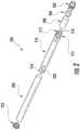
- FIG. 4illustrates an exploded perspective view of a cartridge 500 for use in an aerosol delivery device, according to an example implementation of the present disclosure.
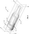
- FIG. 5illustrates a perspective view of the cartridge 500 of FIG. 4 in an assembled configuration, according to an example implementation of the present disclosure
- FIG. 6illustrates a cross-section view, taken along section line A-A, of the cartridge 500 of FIG. 5 , according to an example implementation of the present disclosure
- FIG. 7illustrates a cross-section view, taken along section line B-B, of the cartridge 500 of FIG. 5 , according to an example implementation of the present disclosure.
- components of an aerosol delivery devicean in particular, the control body for use with the illustrated cartridge, may be substantially similar to, or the same as, corresponding components described above.
- the cartridge 500 of the depicted implementationincludes the following components: a center pin 502, a connector 504, an insulating ring 506, a lower atomizer seal 508, an atomizer 510 (which includes a liquid transport element 512 and a heating element 514), an upper atomizer seal 516, a lower base seal 518, a cartridge base 520, a flavor ring 522, a masking ring 524, an upper base seal 526, an aerosol tube 528, and a reservoir tank 530.
- the cartridge 500 of FIGS. 4-7may be configured to releasably engage a control body so as to create an aerosol delivery device.
- control bodymay be similar to, or the same as the control body 200 described above (see, FIG. 2 ), and hence description thereof will not be repeated. It should be noted, however, that in other implementations the control body may differ from that described above. In addition, in some implementations, the control body of the aerosol delivery device may have different shape than that described above, such as, for example, a hand-held fob-shaped control body.
- the connector 504 of the cartridge 500is fixedly attached to the cartridge base 520.
- the surface 532 of the connector 504 that interfaces with the cartridge base 520has an outside diameter that is larger than an inside diameter of the cartridge base 520 and includes a knurl pattern created thereon such that when the connector 504 is pressed into the cartridge base 520 (e.g, to create a transition fit or interference fit), the connector 504 and the cartridge base 520 are fixed together.
- the connector 504 and the cartridge base 520may be fixedly attached by other means, including, but not limited to, the use of various adhesives, and/or other mechanical attachment means, including, for example, the use of mechanical locking features located on one or both the connector and the cartridge base.
- the connector 504may constructed of a conductive material, such as a metal material
- the cartridge base 520may be constructed of an insulating material, such as a rubber or plastic material.
- a fixed relationship between the connector 504 and the cartridge base 520may be created by insert molding the connector 504 into the cartridge base 520.
- the connectoris constructed of brass C3604 and is plated with a copper-nickel (CuNi) plating, although in other implementations, other materials, including stainless steel, are possible.
- the cartridge base 520is constructed of Tritan TM (a copolymer material), although in other implementations, other materials, including aluminum, are possible.
- the connector 504 of the cartridge 500comprises a male connector, with external threads 534, which are configured to engage corresponding internal threads of a female connector (not shown), which may be part of the control body 200.
- the connector 504 of the cartridge 500may comprise a female connector and the control body 200 may include a corresponding male connector.
- the connector 504 of the cartridge 500 and the corresponding connector of the control body 200are configured such that, when threaded together and tightened, the cartridge base 520 and the control body 200 do not easily move relative to each other without unscrewing the cartridge 500 from the control body 200. It should be noted that in other implementations, such a relationship may be created using other connecting means.
- the cartridge base and the control bodymay be connected using a snap connection and/or a bayonet connection, wherein the cartridge base (or the control body) may include one or more pins, and the control body (or cartridge base) may include one or more corresponding L-shaped slots.
- the lower atomizer seal 508engages with the connector 504 at an upper end thereof and is also configured to receive an upper end of the center pin 502 through a central channel 511 (see FIG. 9B ).
- the center pin 502is constructed of a conductive material, which may be the same material or a different material as the connector 504.
- the center pin 502may be constructed of a metal material.
- the connector 504 and the center pin 502serve as electrical connectors for the atomizer 510, and thus the insulating ring 506 and the lower atomizer seal 508 are configured to isolate (at least electrically) the connector 504 and the center pin 502 from each other.
- the insulating ring 506sealingly engages an internal annular flange 536 of the connector 504, and the lower atomizer seal 508 sealingly engages an inner surface of the connector 504 as well as an inner surface of the cartridge base 520.
- the insulating ring 506 and the lower atomizer seal 508are constructed of an insulating material, such as, for example, a rubber or plastic material.
- the insulating ring 506 and the lower atomizer seal 508may comprise silicone, thermoplastic polyurethane, or another resilient material.
- the center pin 502is constructed of brass C3604 and is plated with a copper-nickel (CuNi) plating
- the insulting ring 506 and upper atomizer seal 516are constructed of silicone, shore hardness 60A
- the lower atomizer seal 508is constructed of silicone, shore hardness 65A. It should be noted, however, that in other implementations, various other materials are possible for any of the components of the cartridge 500.
- the lower atomizer seal 508is also configured to locate the atomizer 510, which in the depicted implementation, comprises a liquid transport element 512 and a heating element 514, which, in some implementations, may comprise a wire.
- the liquid transport element 512may comprise a porous monolith.
- the liquid transport element 512may comprise a ceramic material such that aerosol precursor composition delivered to the liquid transport element 512 may be absorbed therein for aerosolization.
- the heating element 514may be wrapped or coiled around the liquid transport element 512, as shown.
- the wire of the heating element 514may comprise titanium, Kanthal (FeCrAl), Nichrome, Molybdenum disilicide (MoSi 2 ), molybdenum silicide (MoSi), Molybdenum disilicide doped with Aluminum (Mo(Si,Al) 2 ), graphite and graphite-based materials; ceramic (e.g., a positive or negative temperature coefficient ceramic), Tungsten, and Tungsten-based alloys, or any other suitable materials, such as those noted elsewhere herein. Tungsten and Tungsten-based alloys may be useful in that these materials may define a coefficient of expansion suitable for usage with many ceramics, which may be employed in the liquid transport element 512.
- one end of the heating element 514contacts the conductive center pin 502, which, when connected to the control body, receives a positive connection to the power unit, and the other end of the heating element 514 contacts the conductive connector 504, which receives a negative connection to the power unit.
- the atomizer 510may be formed by winding a wire about a liquid transport element as described in U.S. Pat. No. 9,210,738 to Ward et al., which is incorporated herein by reference in its entirety.
- various other methodsmay be employed to form the atomizer 510, and various other implementations of a heating element may be employed in the atomizer.
- a heating elementmay be configured to heat the aerosol precursor composition disposed within a liquid transport element via radiant heating, as described in U.S. Pat. App. Pub. No. 2017/0020193, filed December 3, 2015 , the content of which is incorporated herein by reference in its entirety.
- the heating element 316may be configured to heat the aerosol precursor composition via inductive heating, as described in U.S. Pat. App. Pub. No. 2017/0127722, filed November 6, 2015 , the content of which is incorporated herein by reference in its entirety.
- the wire of the heating element 514may be at least partially imbedded in the liquid transport element 512.
- the wire of the heating element 514may be imbedded in the liquid transport element 512 before the liquid transport element 512 is fired in a high temperature oven known as a kiln.
- the wiremay be wrapped about a long section of the base material from which the ceramic is formed prior to firing the material.
- base materials employed to form the ceramic in the liquid transport element 512may include clay, oxides, nonoxides, and composites.
- the wiremay at least partially imbed in the base material during wrapping thereabout.
- the base material and the wiremay then be fired in the kiln. Afterwards, a saw or other cutting device may divide the product into individual atomizers having a desired length.
- the atomizer 510is also located by an upper atomizer seal 516, which is also configured to sealingly engage an inside surface of an upper portion of the cartridge base 520.
- the upper atomizer seal 516is constructed of an insulating material, such as, for example, a rubber or plastic material.
- the upper atomizer seal 516is constructed of silicone.
- An atomizer chamber 540is formed around the atomizer 510 and is bounded by an inner chamber 542 of the lower atomizer seal 508 (and a top portion of the center pin 502) and an inner chamber 544 of the upper atomizer seal 516 (see FIG. 7 ).
- the atomizer 510When assembled, the atomizer 510 (i.e., the liquid transport element 512 and the heating element 514) traverses across the atomizer chamber 540.
- An end of the upper atomizer seal 516 opposite the atomizer chamber 540is configured to receive the aerosol tube 528, the opposite end of which is configured to extend inside a portion of an aerosol channel 546 of the reservoir tank 530.
- the aerosol channel 546 of the reservoir tank 530extends through the reservoir tank 530 and terminates at an opening 548 (see FIG. 11 ) at a mouth end 550 of the reservoir tank 530.
- an internal annular flange 549 of the upper atomizer seal 516locates one end of the aerosol tube 528.
- the aerosol tube 528may be made of a variety of materials, including various plastic or metal materials, in the depicted implementation, the aerosol tube is constructed of 304 stainless steel.
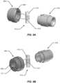
- FIG. 8illustrates a perspective view of the cartridge base 530, according to an example implementation of the present disclosure.
- the cartridge base 530generally includes a lower body portion 552 and an upper extension 554.
- the upper extension 554includes a locating flange 555, which includes chamfered leading and trailing edges (see FIGS. 6 and 7 ) that are received by a locating feature of the reservoir tank 530.
- the lower body portion 552is configured to be proximate the control body 200 when assembled, and includes a seal groove 556 configured to receive the lower base seal 518, and a coupling surface 558, to which the flavor disc 522 is attached.
- the coupling surface 558includes a series of openings 560, each of which creates a separate flavor duct 562 leading to a liquid chamber 564 (see FIGS. 6 and 7 ) that extends peripherally above the lower atomizer seal 508 and around the liquid transport element 512.
- a pair of transport grooves 566located in the lower atomizer seal 508 that are proximate the ends of the liquid transport element 512 allow liquid from the liquid chamber 564 to enter a central chamber 568 of the liquid transport element 512.
- each flavor duct 562may be configured to impart a respective flavor to an initial aerosol precursor composition 602 from the reservoir tank 530.
- the coupling surface 558 of the cartridge base 530may include a solid portion 570 wherein the respective area is devoid of a flavor opening (and thus devoid of a flavor duct).
- the solid portion 570 of the coupling surfacemay correspond with a solid section 575 of the flavor disc 522, as will be discussed in more detail below.
- the flavor disc 522is constructed of the same material as the cartridge base 520, in particular, Tritan TM , although in other implementations, other materials are possible, and the cartridge base 520 and the flavor disc 522 need not be constructed of the same material.
- FIG. 10illustrates a perspective view of the flavor disc 522 fixedly coupled to the cartridge base 520.
- the flavor disc 522may be fixedly coupled to the cartridge base in a variety of ways.
- this attachmentmay be via a mechanical interface, such as, for example, where an inner diameter of the masking disc is smaller than an outer diameter of a mating surface of the cartridge base 520 (e.g, to create a transition fit or interference fit).
- this attachmentmay be via use of one or more adhesives.
- the masking discmay be part of the cartridge base such that the flavor disc and reservoir tank comprise a unitary part.
- the flavor disc 522may include two or more separate sections that are configured to permit the initial aerosol precursor composition to pass therethrough, and at least one of the sections may comprise a flavor section 572 that contains a flavorant.
- the initial aerosol precursor composition 602may comprise an unflavored aerosol precursor composition or a flavored aerosol precursor composition (i.e., an aerosol precursor composition that includes one or more flavorants).
- a flavorantrefers to compounds or components that can be aerosolized and delivered to a user and which impart a sensory experience in terms of taste and/or aroma.
- Exemplary flavorantsinclude, but are not limited to, vanillin, ethyl vanillin, cream, tea, coffee, fruit (e.g., apple, cherry, strawberry, peach and citrus flavors, including lime and lemon), maple, menthol, mint, peppermint, spearmint, wintergreen, nutmeg, clove, lavender, cardamom, ginger, honey, anise, sage, rosemary, hibiscus, rose hip, yerba mate, guayusa, honeybush, rooibos, yerba santa, bacopa monniera, gingko biloba, withania somnifera, cinnamon, sandalwood, jasmine, cascarilla, cocoa, licorice, and flavorings and flavor packages of the type and character traditionally used for the flavoring of cigarette, cigar, and pipe tobaccos.
- fruite.g., apple, cherry, strawberry, peach and citrus flavors, including lime and lemon
- maplementhol
- mintpeppermint
- Syrupssuch as high fructose corn syrup, also can be employed.
- Exemplary plant-derived compositions that may be suitableare disclosed in U.S. Pat. No. 9,107,453 and U.S. Pat. App. Pub. No. 2012/0152265 both to Dube et al., the disclosures of which are incorporated herein by reference in their entireties.
- the selection of such further componentsare variable based upon factors such as the sensory characteristics that are desired for the smoking article, and the present disclosure is intended to encompass any such further components that are readily apparent to those skilled in the art of tobacco and tobacco-related or tobacco-derived products. See, e.g., Gutcho, Tobacco Flavoring Substances and Methods, Noyes Data Corp.
- flavorantshould not be limited to any single flavorant as described above, and may, in fact, represent a combination of one or more flavorants.
- the flavor disc 522 of the depicted implementationincludes nine total sections, with eight of the sections representing separate flavor sections 572.
- the flavor disc 522may be constructed of one or more various materials, for clarity of illustration, the flavor disc 522 is shown in the drawings as being transparent and the flavor sections 572 are represented by different colors, each of which contains a separate flavorant. It should be noted, however, that in other implementations, there may be any number of sections, wherein any of the sections may be a flavor section. In addition, in some implementations, there may be one or more bypass sections wherein the section does not include a flavorant such that no flavor is mixed with the aerosol precursor composition.
- the cartridgemay include more than one solid section, and, in some implementations, the cartridge may not include a solid section.
- a flavor section 572may comprise a section of the flavor disc 522 that includes a flavorant in a liquid form.
- a flavor section 572may comprise a substrate or other material in which the flavorant is absorbed or otherwise contained.
- a flavor section 572may comprise carbon materials, ceramics, polymers, composites, metals, cellulosics, and the like.
- the materialmay either be porous (e.g., a porous carbon material) or in the form of a gel or coating that allows transport of the flavorant to the initial aerosol precursor composition for volatilization.
- FIG. 13An example of a flavor disc 522 according to another implementation of the present disclosure is illustrated in FIG. 13 .
- the flavor disc 522includes a plurality of flavor sections 572, each of which comprises an outer shell 578 defining an inner surface 580 that surrounds an inner chamber 582.
- the outer shell 578comprises a porous material that contains a flavorant
- the inner chamber 582is configured to allow the aerosol precursor composition to flow therethrough and against the inner surface 580, thus imparting the initial aerosol precursor composition with the flavorant, such as, for example, by mixing the flavorant with the initial aerosol precursor composition.
- each of which contains a separate flavorantthere are eight separate flavor sections 572, each of which contains a separate flavorant, however, as noted above there may be any number of sections, wherein one or more of the sections may include the same or different flavorants, and one or more of sections may be bypass sections.
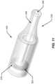
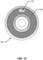
- FIG. 11illustrates a perspective view of a reservoir tank 530 and masking disc 524
- FIG. 12illustrates a back view of the reservoir tank 530 and masking disk 524, according to an example implementation of the present disclosure
- the reservoir tank 530may be constructed of one or more of a variety of materials, including, for example, a metal material, a glass material, and/or a plastic material, such as, for example, an acrylic material (e.g., polymethlamethacrylate).
- the reservoir tank 530may comprise a translucent or transparent material, such that a user may view the quantity of the aerosol precursor composition remaining therein.
- the reservoir tank 530is constructed of polypropelene or Tritan TM , although in other implementations, other materials are possible
- the masking disc 524may be configured to be fixedly attached to the lower portion of the reservoir tank 530. In one example implementation, this attachment may be via a mechanical interface, such as, for example, where an outer diameter of the masking disc is larger than an inner diameter of the mating surface of the reservoir tank 530 (e.g, to create a transition fit or interference fit). In another example implementation, the masking disc 524 may be ultrasonically welded to the reservoir tank 530. In other implementations, this attachment may be via use of one or more adhesives. In still other implementations, the masking disc 524 may be part of the reservoir tank 530 such that the masking disc 534 and reservoir tank 530 comprise a unitary part.
- the masking disc 524is configured to substantially seal the liquid cavity 574, except for an opening 576 formed in the masking disc 524.
- various other mechanisms and techniquesmay be employed to retain the masking disc 524 in engagement with the reservoir tank 530.
- ultrasonic weldingmay be useful in that it may provide a hermetic seal without requiring an additional component or substance to form the seal.
- the opening 576 in the masking disc 524is configured to allow the initial aerosol precursor composition 602 to flow therethrough.
- the masking disc 524may be constructed of a similar material as the reservoir tank 530.
- the masking disc 524is constructed of Tritan TM , although in other implementations, other materials are possible, such as, for example, polypropylene or a stamped metal, such as stainless steel or aluminum.
- the reservoir tank 530may comprise a housing that includes an aerosol channel 546 that extends from one end proximate the upper extension 554 of the cartridge base 520 (when assembled) and terminates at the opening 548 at the mouth end 550 of the reservoir tank 530.
- the housingalso includes a locating groove 557, which is configured (when assembled) to engage the locating flange 555 of the cartridge base 520.
- the housingalso defines a substantially cylindrical liquid cavity 574 that extends around, but does not intersect, the aerosol channel 546.
- the liquid cavity 574is configured to contain the initial aerosol precursor composition 602, and the aerosol channel 546 is configured to carry the resulting aerosol 606 through the opening 548 in the mouth end 550 of the reservoir tank 530.
- the aerosol channel 546may be formed of an outer wall of the housing that is substantially shaped as a cylindrical tube and is disposed interior to the liquid chamber 574 of the reservoir tank 530.
- the lower base seal 518forms a seal between the cartridge base 520 and the reservoir tank 530
- the upper base seal 526forms a seal between the reservoir tank 530 and the aerosol tube 528.
- the lower base seal 518 and the upper base seal 526comprise O-rings constructed of a synthetic rubber or thermoplastic material, although other materials and constructions are possible.
- the center pin 502, connector 504, insulating ring 506, lower atomizer seal 508, atomizer 510, upper atomizer seal 516, lower cartridge base seal 518, flavor disc 522, upper cartridge base seal 526, and aerosol tube 528form a cartridge base assembly.
- the reservoir tank 530 and masking disc 522form a reservoir assembly.
- the reservoir assemblyis configured to be coupled to cartridge assembly by sliding the reservoir assembly onto the cartridge base assembly such that the locating flange 555 of the cartridge base 520 is received by and/or engages with the locating groove 557 of the reservoir tank 530. In such a manner, after the reservoir assembly has been coupled to the cartridge base assembly, the reservoir assembly is configured to rotate relative to the cartridge base assembly.
- the cartridge 500is removably attached to the control body 200 via the external threads 534 of the connector 504 by tightening the threaded connector 504 against the control body 200. Because in the depicted implementation the connector 504 and the cartridge base 520 are fixedly attached to each other as described above, when the cartridge 500 is attached to the control body 200 and tightened, the cartridge base 520 and the control body 200 do not easily move relative to each other.
- the center pin 502, insulating ring 506, lower atomizer seal 508, atomizer 510, upper atomizer seal 516, flavor disc 522, and aerosol tube 528also do not typically move relative to the cartridge base 520, and thus when assembled, the reservoir tank 530 and masking disc 524 are configured to rotate relative to these components. As a result, the masking disc 524 may be rotated relative to the flavor disc 522 via rotation of the reservoir tank 530. Thus, a consumer may selectively align the opening 576 of the masking disc 524 with a selected flavor section 572 by rotating the reservoir tank 530 to the appropriate location.
- the cartridge 500 and/or control bodymay include one or more indicators to aid the consumer in determining a rotation location.
- the cartridge 500 and/or the control bodymay include visual indicators, such as a plurality of markings, thereon so as to indicate the locations of the various flavor sections of the flavor disc 522.
- the cartridge 500 and/or control bodymay include one or more audible or tangible indicators, such as, for example, a series of detents (which, in some implementations, may also include a sound) that indicate the location of the various flavor sections.
- audible or tangible indicatorssuch as, for example, a series of detents (which, in some implementations, may also include a sound) that indicate the location of the various flavor sections.
- the initial aerosol precursor composition 602 contained in the liquid cavity 574will pass through the selected flavor section 572 before entering the atomizer chamber 540.
- the initial aerosol precursor composition 602will mix with the flavorant in the selected flavor section 572 such that the flavorant is imparted to the initial aerosol precursor composition 602 and the resultant aerosol precursor composition comprises a flavored aerosol precursor composition 604 (i.e., an initial aerosol precursor composition mixed with the flavorant).
- the flavored aerosol precursor composition 604then flows through the corresponding flavor duct 562 of the cartridge base 520 and into the liquid chamber 564 that extends peripherally above the lower atomizer seal 508 and around the liquid transport element 512.
- the transport grooves 566 located in the lower atomizer seal 508allow the flavored aerosol precursor composition 604 to contact the liquid transport element 512 and/or enter the central chamber 568 thereof such that the wetted liquid transport element 512 may be aerosolized by the heater coil 514.
- FIG. 6illustrates flow of the initial aerosol precursor composition 602 through the opening 576 in the masking disc 524, through the selected flavor section 572 of the flavor disc 522, into the liquid chamber 564, onto the liquid transport element 512, and into the central chamber 568 thereof.
- the channels and pathways described abovemay be configured such that the flow of the initial aerosol precursor composition 602 and the flavored aerosol precursor composition 604 may occur via capillary action. In such a manner, the flow of the initial aerosol precursor composition 602 and the flavored aerosol precursor composition 604 may occur in any orientation of the cartridge 500. Further, an entrained volume of the initial aerosol precursor composition 602 and the flavored aerosol precursor composition 604 in the various downstream components may allow for continued operation in any orientation.
- unidirectional flow of the aerosol precursor compositionmay be accomplishing using differences in the porosity of the components through which the aerosol precursor composition flows.
- the material of the flavor section 572 through which the initial aerosol precursor composition 602 flowsmay have one porosity
- the material of flavor ducts 562 through which the flavored aerosol precursor composition 604 flowsmay have a smaller porosity
- the material of the liquid transport element 512 into which the flavored aerosol precursor composition flowsmay have an even smaller porosity, such that the liquid is drawn in one direction from the liquid cavity 574 to the liquid transport element 512.
- unidirectional flowmay be accomplished via other means.
- the materials through which the aerosol precursor compositions flowmay have progressively decreasing contact angles such that the liquid is drawn in one direction from the liquid cavity 574 to the liquid transport element 512.
- the various liquid orifices and channels described abovemay be configured such that the flow of the initial aerosol precursor composition 602 and the flavored aerosol precursor composition 604 may provide for the precise transfer of a desired amount of aerosol precursor composition from the liquid cavity 574 to the atomizer chamber 540.
- the various aerosol precursor composition orifices and channelsmay be shaped and/or configured so as to provide for the transfer of small volumes of liquid (i.e., the initial aerosol precursor composition and/or the flavored aerosol precursor composition), such as milliliter or smaller, microliter or smaller, from the liquid chamber 574 to the atomizer chamber 540.
- one or more of the aerosol precursor composition orifices and channelsmay be shaped and/or configured so as to substantially limit and/or prevent any amount of aerosol precursor composition retained within the liquid cavity 574 from vaporizing prematurely (i.e., vaporizing before being provided to the atomizer chamber 540).
- the various aerosol precursor composition orifices and channelsmay be shaped and/or configured such that a pressure within the liquid cavity 574 does not decrease past an operational threshold during use of the aerosol delivery device.
- the various aerosol precursor composition orifices and channelsmay be sized in response to the surface energy of the aerosol precursor composition retained within the liquid cavity 574.
- the aerosol precursor composition orifice(s) and channelsmay have a size in the range of about 0.02 mm to about 0.11 mm, about 0.03 mm to about 0.1 mm, or about 0.04 mm to about 0.09 mm.
- each orifice or channelmay have substantially the same size, or two or more orifices or channels may have different sizes.
- An electrical connection between the control body 200 and the atomizer 510 via the two ends of the heating element 514allows the control body 200 to direct electrical current to the atomizer 510, such as upon actuation by the user (e.g., via a button) and/or when a puff on the aerosol delivery device is detected.
- the longitudinal end of the cartridge 500 opposite the cartridge base 520defines the mouth end 550 of the reservoir tank 530.
- air 600may be directed through one or more air intakes in the connector 504 from the environment between the connector 504 and the control body.
- the air 600 drawn through the air intake(s)may then be drawn around the center pin 502, along a slot in the bottom thereof, and through the center of the center pin 502, such that the air 600 exits through one or more peripheral openings into an annular area of the connector 504. From there, the air 600 is drawn through one or more openings 538 (see FIG. 9B ) in the bottom of the lower atomizer seal 508 and into the atomizer chamber 540.
- a flow sensor(see e.g., FIG. 2 ) may detect the draw.
- the control body 200may direct current through the heating element 514 to heat the atomizer 510.
- the flavored aerosol precursor composition 604may be vaporized at the atomizer 510 directly or via heating of the liquid transport element 512.
- the resultant vapor or aerosol 606may be produced at the atomizer chamber 540 and then directed to the user.
- the air 600 enters the atomizer chamber 540it travels past the liquid transport element 512 inside the upper atomizer seal 516.
- the air 600mixes with the vaporized flavored aerosol precursor composition 604 and becomes the aerosol 606.
- the aerosol 606may then travel through upper atomizer seal 516, into the aerosol tube 528, and out of the mouth end 550 of the cartridge 500 to the user through the aerosol channel 546.
- FIG. 14schematically illustrates an aerosol delivery device operation method, according to an example implementation of the present disclosure.
- the aerosol delivery devicemay comprise a cartridge and a control body.
- the method 700may comprise providing a cartridge that includes a reservoir containing an initial aerosol precursor composition, a masking disc proximate the reservoir, a flavor disc proximate the masking disc, and an atomizer at operation 702.
- the reservoir, masking disc, flavor disc, initial aerosol precursor composition, and atomizermay be configured as described above with respect to FIGS. 4-13 .
- the method 700may further comprise rotating the masking disc relative to the flavor disc to select a flavor section of the flavor disc at operation 704.
- thismay comprise aligning an opening in the masking disc with a selected flavor section of the flavor disc.
- the method 700may further comprise directing the initial aerosol precursor composition through the selected flavor section of the flavor disc to create a flavored aerosol precursor composition.
- thismay comprise allowing the initial aerosol precursor composition to flow through a flavor section of the flavor disc and into an atomizer chamber (for example, via capillary action) such that the initial aerosol precursor composition is imparted with the flavorant from the selected flavor section of the flavor disc.
- the method 700may further comprise directing an electrical current from a control body to the atomizer to aerosolize the flavored aerosol precursor composition at operation 708. In various implementations, this may comprise heating a heater coil that heats a liquid transport element that contains the flavored aerosol precursor composition so as to vaporize the flavored aerosol precursor composition.
- both the masking disc and the flavor discmay be configured to be rotated independently. In such a manner, a user may control the relative amount of flavorant added to the initial aerosol precursor composition from a selected flavor section.
- the flavor discmay rotate and there may be a common liquid path leading to the atomizer chamber. In such a manner, a user may rotate the flavor disc to select a flavor section so as to direct the initial aerosol precursor composition through the selected flavor section to create the flavored aerosol precursor composition, which then flows through the common path to the atomizer chamber.
- the liquid tank and the flavor discmay have separate paths leading to the atomizer chamber. In such a manner, the separate paths may converge before the atomizer chamber or may separately lead to the atomizer chamber.
- the selection of a flavor section and/or the flow of the initial aerosol precursor composition and/or the flow of the flavored aerosol precursor compositionmay be controlled via one or more electronically controlled valves.
- the flavor sectionmay comprise two parallel channels wherein one channel allows the initial aerosol precursor composition to flow therethrough to the aerosol chamber without being mixed with the flavorant, and the other channel delivers the flavorant directly to aerosol chamber. In such a manner, the initial precursor composition may be mixed with the flavorant in the aerosol chamber.
Landscapes
- Containers And Packaging Bodies Having A Special Means To Remove Contents (AREA)
Abstract
Description
- The present disclosure relates to aerosol delivery devices, and more particularly to an aerosol delivery device that include a reservoir and a vaporizing assembly, which may utilize electrical power to heat an aerosol precursor composition for the production of an aerosol. The aerosol precursor composition, which may incorporate materials and/or components that may be made or derived from tobacco or otherwise incorporate tobacco, is heated by the vaporizing assembly to produce an inhalable substance for human consumption.
- Many smoking articles have been proposed through the years as improvements upon, or alternatives to, smoking products based upon combusting tobacco. Exemplary alternatives have included devices wherein a solid or liquid fuel is combusted to transfer heat to tobacco or wherein a chemical reaction is used to provide such heat source. Examples include the smoking articles described in
U.S. Patent No. 9,078,473 to Worm - The point of the improvements or alternatives to smoking articles typically has been to provide the sensations associated with cigarette, cigar, or pipe smoking, without delivering considerable quantities of incomplete combustion and pyrolysis products. To this end, there have been proposed numerous smoking products, flavor generators, and medicinal inhalers which utilize electrical energy to vaporize or heat a volatile material, or attempt to provide the sensations of cigarette, cigar, or pipe smoking without burning tobacco to a significant degree. See, for example, the various alternative smoking articles, aerosol delivery devices and heat generating sources set forth in the background art described in
U.S. Pat. No. 7,726,320 to Robinson et al.; andU.S. Pat. App. Pub. Nos. 2013/0255702 to Griffith, Jr. et al.; and2014/0096781 to Sears et al. , which are incorporated herein by reference. See also, for example, the various types of smoking articles, aerosol delivery devices and electrically powered heat generating sources referenced by brand name and commercial source inU.S. Pat. App. Pub. No. 2015/0220232 to Bless et al. , which is incorporated herein by reference. Additional types of smoking articles, aerosol delivery devices and electrically powered heat generating sources referenced by brand name and commercial source are listed inU.S. Pat. App. Pub. No. 2015/0245659 to DePiano et al., which is also incorporated herein by reference in its entirety. Other representative cigarettes or smoking articles that have been described and, in some instances, been made commercially available include those described inU.S. Pat. No. 4,735,217 to Gerth et al.;U.S. Pat. Nos. 4,922,901 ,4,947,874 , and4,947,875 to Brooks et al.;U.S. Pat. No. 5,060,671 to Counts et al.;U.S. Pat. No. 5,249,586 to Morgan et al.;U.S. Pat. No. 5,388,594 to Counts et al.;U.S. Pat. No. 5,666,977 to Higgins et al.;U.S. Pat. No. 6,053,176 to Adams et al.;U.S. Pat. No. 6,164,287 to White ;U.S. Pat No. 6,196,218 to Voges ;U.S. Pat. No. 6,810,883 to Felter et al.;U.S. Pat. No. 6,854,461 to Nichols ;U.S. Pat. No. 7,832,410 to Hon ;U.S. Pat. No. 7,513,253 to Kobayashi ;U.S. Pat. No. 7,726,320 to Robinson et al.;U.S. Pat. No. 7,896,006 to Hamano ;U.S. Pat. No. 6,772,756 to Shayan ;U.S. Pat. App. Pub. No. 2009/0095311 to Hon ;U.S. Pat. App. Pub. Nos. 2006/0196518 ,2009/0126745 , and2009/0188490 to Hon ;U.S. Pat. App. Pub. No. 2009/0272379 to Thorens et al.;U.S. Pat. App. Pub. Nos. 2009/0260641 and2009/0260642 to Monsees et al.;U.S. Pat. App. Pub. Nos. 2008/0149118 and2010/0024834 to Oglesby et al.;U.S. Pat. App. Pub. No. 2010/0307518 to Wang ; andWO 2010/091593 to Hon , which are incorporated herein by reference. - Representative products that resemble many of the attributes of traditional types of cigarettes, cigars or pipes have been marketed as ACCORD® by Philip Morris Incorporated; ALPHA™, JOYE 510™ and M4™ by InnoVapor LLC; CIRRUS™ and FLING™ by White Cloud Cigarettes; BLU™ by Lorillard Technologies, Inc.; COHITA™, COLIBRI™, ELITE CLASSIC™, MAGNUM™, PHANTOM™ and SENSE™ by EPUFFER® International Inc.; DUOPRO™, STORM™ and VAPORKING® by Electronic Cigarettes, Inc.; EGAR™ by Egar Australia; eGo-C™ and eGo-T™ by Joyetech; ELUSION™ by Elusion UK Ltd; EONSMOKE® by Eonsmoke LLC; FIN™ by FIN Branding Group, LLC; SMOKE® by Green Smoke Inc. USA; GREENARETTE™ by Greenarette LLC; HALLIGAN™, HENDU™, JET™, MAXXQ™, PINK™ and PITBULL™ by SMOKE STIK®; HEATBAR™ by Philip Morris International, Inc.; HYDRO IMPERIAL™ and LXE™ from Crown7; LOGIC™ and THE CUBAN™ by LOGIC Technology; LUCI® by Luciano Smokes Inc.; METRO® by Nicotek, LLC; NJOY® and ONEJOY™ by Sottera, Inc.; NO. 7™ by SS Choice LLC; PREMIUM ELECTRONIC CIGARETTE™ by PremiumEstore LLC; RAPP E-MYSTICK™ by Ruyan America, Inc.; RED DRAGON™ by Red Dragon Products, LLC; RUYAN® by Ruyan Group (Holdings) Ltd.; SF® by Smoker Friendly International, LLC; GREEN SMART SMOKER® by The Smart Smoking Electronic Cigarette Company Ltd.; SMOKE ASSIST® by Coastline Products LLC; SMOKING EVERYWHERE® by Smoking Everywhere, Inc.; V2CIGS™ by VMR Products LLC; VAPOR NINE™ by VaporNine LLC; VAPOR4LIFE® by Vapor 4 Life, Inc.; VEPPO™ by E-CigaretteDirect, LLC; VUSE® by R. J. Reynolds Vapor Company; Mistic Menthol product by Mistic Ecigs; and the Vype product by CN Creative Ltd. Yet other electrically powered aerosol delivery devices, and in particular those devices that have been characterized as so-called electronic cigarettes, have been marketed under the tradenames COOLER VISIONS™; DIRECT E-CIG™; DRAGONFLY™; EMIST™; EVERSMOKE™; GAMUCCI®; HYBRID FLAME™; KNIGHT STICKS™; ROYAL BLUES™; SMOKETIP®; SOUTH BEACH SMOKE™.
- Certain existing embodiments of aerosol delivery devices include a control body (i.e., a power source assembly) and cartridge (i.e., a reservoir housing). A power source (e.g., a battery) may be positioned in the control body, and an aerosol precursor composition may be retained and/or stored within the cartridge. It would be desirable to provide a cartridge capable of adding one or more flavor additives to the aerosol precursor composition as desired by the user.
- The present disclosure relates to aerosol delivery devices and cartridges for use in aerosol delivery devices. The present disclosure includes, without limitation, the follow example implementations:
- Example Implementation 1: An aerosol delivery device comprising a control body, a cartridge comprising a reservoir tank configured to contain an aerosol precursor composition, a masking disc proximate the aerosol precursor composition, the masking disc including an opening configured to the permit aerosol precursor composition to pass therethrough, and a flavor disc proximate the masking disc, the flavor disc including two or more separate sections, wherein at least two of the sections are configured to permit the aerosol precursor composition to pass therethrough, and at least one of the sections comprises a flavor section that contains a flavorant, and an atomizer configured to receive the aerosol precursor composition and produce an aerosol, wherein at least one of the masking disc or the flavor disc is configured to be rotated relative to the other to align the opening of the masking disc with a selected section of the flavor disc so as to allow the aerosol precursor composition to flow from the reservoir tank through the opening of the masking disc and the selected section of the flavor disc to the atomizer such that, when the flavor section is selected, the flavorant is imparted to the aerosol precursor composition delivered to the atomizer.
- Example Implementation 2: The aerosol delivery device of any preceding example implementation, or any combination of any preceding example implementations, wherein the flavor disc further comprises a solid section configured to block the flow of the aerosol precursor composition when the opening of the masking disc is aligned therewith.Example Implementation 3: The aerosol delivery device of any preceding example implementation, or any combination of any preceding example implementations, further comprising a cartridge base that includes two or more passageways, wherein each passageway is configured to align with a separate section of the flavor disc so as to facilitate flow of the aerosol precursor composition from the reservoir tank through the selected flavor disc section and to the atomizer.Example Implementation 4: The aerosol delivery device of any preceding example implementation, or any combination of any preceding example implementations, wherein the masking disc is affixed to the reservoir tank, and wherein the reservoir tank is configured to be rotated so as to rotate the masking disc to align the opening of the masking disc with a selected section of the flavor disc.Example Implementation 5: The aerosol delivery device of any preceding example implementation, or any combination of any preceding example implementations, wherein the reservoir tank comprises a housing that includes a liquid cavity defined therein, and wherein the liquid cavity is configured to contain the aerosol precursor composition.Example Implementation 6: The aerosol delivery device of any preceding example implementation, or any combination of any preceding example implementations, wherein the cartridge defines a mouth end and a connecting end, and wherein the connecting end includes a threaded portion configured to thread into an engaging end of the control body.Example Implementation 7: The aerosol delivery device of any preceding example implementation, or any combination of any preceding example implementations, wherein the flavor disc includes at least three separate sections, wherein one of the sections comprises a solid section, wherein at least two other sections comprise flavor sections, and wherein at least two of the flavor sections contain different flavorants.Example Implementation 8: The aerosol delivery device of any preceding example implementation, or any combination of any preceding example implementations, wherein the flavor disc includes nine separate sections, wherein one of the sections comprises a solid section, wherein the eight other sections comprise flavor sections, and wherein each of the flavor sections contains a different flavorant.Example Implementation 9: The aerosol delivery device of any preceding example implementation, or any combination of any preceding example implementations, further comprising a cartridge base that includes eight passageways, wherein each passageway is configured to align with a separate respective flavor section of the flavor disc so as to facilitate flow of the aerosol precursor composition from the reservoir tank through a selected flavor section and to the atomizer.Example Implementation 10: The aerosol delivery device of any preceding example implementation, or any combination of any preceding example implementations, wherein the flavor section of the flavor disc comprises an outer shell defining an inner surface that surrounds an inner chamber, wherein the outer shell comprises a porous material that contains the flavorant, and wherein the inner chamber is configured to allow the aerosol precursor composition to flow therethrough against the inner surface.
- Example Implementation 11: A cartridge for use in an aerosol delivery device, comprising a reservoir tank configured to contain an aerosol precursor composition, a masking disc proximate the aerosol precursor composition, the masking disc including an opening configured to the permit aerosol precursor composition to pass therethrough, and a flavor disc proximate the masking disc, the flavor disc including two or more separate sections, wherein at least two of the sections are configured to permit the aerosol precursor composition to pass therethrough, and at least one of the sections comprises a flavor section that contains a flavorant, and wherein at least one of the masking disc or the flavor disc is configured to be rotated relative to the other to align the opening of the masking disc with a selected section of the flavor disc so as to allow the aerosol precursor composition to flow from the reservoir tank through the opening of the masking disc and the selected section of the flavor disc, such that, when the flavor section is selected, a flavor from the flavorant is imparted to the aerosol precursor composition.
- Example Implementation 12: The cartridge of any preceding example implementation, or any combination of any preceding example implementations, wherein the flavor disc further comprises a solid section configured to block the flow of the aerosol precursor composition when then opening of the masking disc is aligned therewith.Example Implementation 13: The cartridge of any preceding example implementation, or any combination of any preceding example implementations, further comprising a cartridge base that includes two or more passageways, wherein each passageway is configured to align with a separate section of the flavor disc so as to facilitate flow of the aerosol precursor composition from the reservoir tank through the selected flavor disc section.Example Implementation 14: The cartridge of any preceding example implementation, or any combination of any preceding example implementations, wherein the masking disc is affixed to the reservoir tank, and wherein the reservoir tank is configured to be rotated so as to rotate the masking disc to align the opening of the masking disc with a selected section of the flavor disc.Example Implementation 15: The cartridge of any preceding example implementation, or any combination of any preceding example implementations, wherein the reservoir tank comprises a housing that includes a liquid cavity defined therein, and wherein the liquid cavity is configured to contain the aerosol precursor composition.Example Implementation 16: The cartridge of any preceding example implementation, or any combination of any preceding example implementations, further comprising a mouth end and a connecting end, and wherein the connecting end includes a threaded portion.Example Implementation 17: The cartridge of any preceding example implementation, or any combination of any preceding example implementations, wherein the flavor disc includes at least three separate sections, wherein one of the sections comprises a solid section, wherein at least two other sections comprise flavor sections, and wherein at least two of the flavor sections contain different flavorants.Example Implementation 18: The cartridge of any preceding example implementation, or any combination of any preceding example implementations, wherein the flavor disc includes nine separate sections, wherein one of the sections comprises a solid section, wherein the eight other sections comprise flavor sections, and wherein each of the flavor sections contains a different flavorant.Example Implementation 19: The cartridge of any preceding example implementation, or any combination of any preceding example implementations, further comprising a cartridge base that includes eight passageways, wherein each passageway is configured to align with a separate respective flavor section of the flavor disc so as to facilitate flow of the aerosol precursor composition from the reservoir tank through a selected flavor section.Example Implementation 20: The cartridge of any preceding example implementation, or any combination of any preceding example implementations, wherein the flavor section of the flavor disc comprises an outer shell defining an inner surface that surrounds an inner chamber, wherein the outer shell comprises a porous material that contains the flavorant, and wherein the inner chamber is configured to allow the aerosol precursor composition to flow therethrough against the inner surface.
- These and other features, aspects, and advantages of the present disclosure will be apparent from a reading of the following detailed description together with the accompanying drawings, which are briefly described below. The present disclosure includes any combination of two, three, four or more features or elements set forth in this disclosure, regardless of whether such features or elements are expressly combined or otherwise recited in a specific example implementation described herein. This disclosure is intended to be read holistically such that any separable features or elements of the disclosure, in any of its aspects and example implementations, should be viewed as intended, namely to be combinable, unless the context of the disclosure clearly dictates otherwise.
- It will therefore be appreciated that this Brief Summary is provided merely for purposes of summarizing some example implementations so as to provide a basic understanding of some aspects of the disclosure. Accordingly, it will be appreciated that the above described example implementations are merely examples and should not be construed to narrow the scope or spirit of the disclosure in any way. Other example implementations, aspects and advantages will become apparent from the following detailed description taken in conjunction with the accompanying drawings which illustrate, by way of example, the principles of some described example implementations.
- In order to assist the understanding of aspects of the disclosure, reference will now be made to the appended drawings, which are not necessarily drawn to scale and in which like reference numerals refer to like elements. The drawings are exemplary only, and should not be construed as limiting the disclosure.
FIG. 1 illustrates a side view of an aerosol delivery device comprising a cartridge and a control body in an assembled configuration, according to an example implementation of the present disclosure;FIG. 2 illustrates an exploded perspective view of the control body ofFIG. 1 , according to an example implementation of the present disclosure;FIG. 3 illustrates an exploded perspective view of the cartridge ofFIG. 1 , according to an example implementation of the present disclosure;FIG. 4 illustrates an exploded perspective view of a cartridge for use in an aerosol delivery device, according to an example implementation of the present disclosure;FIG. 5 illustrates a perspective view of the cartridge ofFIG. 4 in an assembled configuration, according to an example implementation of the present disclosure;FIG. 6 illustrates a cross-section view of the cartridge ofFIG. 5 taken along section line A-A, according to an example implementation of the present disclosure;FIG. 7 illustrates a cross-section view of the cartridge ofFIG. 5 taken along section line B-B, according to an example implementation of the present disclosure;FIG. 8 illustrates a perspective view of a cartridge base, according to an example implementation of the present disclosure;FIG. 9A illustrates an exploded perspective view of a lower atomizer seal, an atomizer, and an upper atomizer seal, according to an example implementation of the present disclosure;FIG. 9B illustrates an exploded rear perspective view of the lower atomizer seal, atomizer, and upper atomizer seal ofFIG. 9A , according to an example implementation of the present disclosure;FIG. 10 illustrates a perspective view of a cartridge base and flavor disc, according to an example implementation of the present disclosure;FIG. 11 illustrates a perspective view of a reservoir tank and masking disc, according to an example implementation of the present disclosure;FIG. 12 illustrates a back view of a reservoir tank and masking disc, according to an example implementation of the present disclosure;FIG. 13 illustrates a front view of a flavor disc, according to another example implementation of the present disclosure; andFIG. 14 schematically illustrates an aerosol delivery device operation method, according to an example implementation of the present disclosure.- The present disclosure will now be described more fully hereinafter with reference to exemplary embodiments thereof. These exemplary embodiments are described so that this disclosure will be thorough and complete, and will fully convey the scope of the disclosure to those skilled in the art. Indeed, the disclosure may be embodied in many different forms and should not be construed as limited to the embodiments set forth herein; rather, these embodiments are provided so that this disclosure will satisfy applicable legal requirements. As used in the specification, and in the appended claims, the singular forms "a", "an", "the", include plural variations unless the context clearly dictates otherwise.
- The present disclosure provides descriptions of aerosol delivery devices. The aerosol delivery devices may use electrical energy to heat a material to form an inhalable substance; such articles most preferably being sufficiently compact to be considered "hand-held" devices. An aerosol delivery device may provide some or all of the sensations (e.g., inhalation and exhalation rituals, types of tastes or flavors, organoleptic effects, physical feel, use rituals, visual cues such as those provided by visible aerosol, and the like) of smoking a cigarette, cigar, or pipe, without any substantial degree of combustion of any component of that article or device. The aerosol delivery device may not produce smoke in the sense of the aerosol resulting from by-products of combustion or pyrolysis of tobacco, but rather, that the article or device most preferably yields vapors (including vapors within aerosols that can be considered to be visible aerosols that might be considered to be described as smoke-like) resulting from volatilization or vaporization of certain components of the article or device, although in other implementations the aerosol may not be visible. In some implementations, aerosol delivery devices may incorporate tobacco and/or components derived from tobacco. As such, the aerosol delivery device can be characterized as an electronic smoking article such as an electronic cigarette or "e-cigarette."
- While the systems are generally described herein in terms of implementations associated with aerosol delivery devices such as so-called "e-cigarettes," it should be understood that the mechanisms, components, features, and methods may be embodied in many different forms and associated with a variety of articles. For example, the description provided herein may be employed in conjunction with implementations of traditional smoking articles (e.g., cigarettes, cigars, pipes, etc.), heat-not-burn cigarettes, and related packaging for any of the products disclosed herein. Accordingly, it should be understood that the description of the mechanisms, components, features, and methods disclosed herein are discussed in terms of embodiments relating to aerosol delivery devices by way of example only, and may be embodied and used in various other products and methods.
- Aerosol delivery devices of the present disclosure also can be characterized as being vapor-producing articles or medicament delivery articles. Thus, such articles or devices can be adapted so as to provide one or more substances (e.g., flavors and/or pharmaceutical active ingredients) in an inhalable form or state. For example, inhalable substances can be substantially in the form of a vapor (i.e., a substance that is in the gas phase at a temperature lower than its critical point). Alternatively, inhalable substances can be in the form of an aerosol (i.e., a suspension of fine solid particles or liquid droplets in a gas). For purposes of simplicity, the term "aerosol" as used herein is meant to include vapors, gases and aerosols of a form or type suitable for human inhalation, whether or not visible, and whether or not of a form that might be considered to be smoke-like.
- In use, aerosol delivery devices of the present disclosure may be subjected to many of the physical actions employed by an individual in using a traditional type of smoking article (e.g., a cigarette, cigar or pipe that is employed by lighting and inhaling tobacco). For example, the user of an aerosol delivery device of the present disclosure can hold that article much like a traditional type of smoking article, draw on one end of that article for inhalation of aerosol produced by that article, take puffs at selected intervals of time, etc.
- Aerosol delivery devices of the present disclosure generally include a number of components provided within an outer shell or body. The overall design of the outer shell or body can vary, and the format or configuration of the outer body that can define the overall size and shape of the aerosol delivery device can vary. Typically, an elongated body resembling the shape of a cigarette or cigar can be a formed from a single, unitary shell; or the elongated body can be formed of two or more separable pieces. For example, an aerosol delivery device can comprise an elongated shell or body that can be substantially tubular in shape and, as such, resemble the shape of a conventional cigarette or cigar. However, various other shapes and configurations may be employed in other embodiments (e.g., rectangular or fob-shaped).
- In one implementation, all of the components of the aerosol delivery device are contained within one outer body or shell. Alternatively, an aerosol delivery device can comprise two or more shells that are joined and are separable. For example, an aerosol delivery device can possess at one end a control body comprising a shell containing one or more reusable components (e.g., a rechargeable battery and various electronics for controlling the operation of that article), and at the other end and removably attached thereto a shell containing a disposable portion (e.g., a disposable flavor-containing cartridge). More specific formats, configurations and arrangements of components within the single shell type of unit or within a multi-piece separable shell type of unit will be evident in light of the further disclosure provided herein. Additionally, various aerosol delivery device designs and component arrangements can be appreciated upon consideration of the commercially available electronic aerosol delivery devices.
- Aerosol delivery devices of the present disclosure most preferably comprise some combination of a power source (i.e., an electrical power source), at least one control component (e.g., means for actuating, controlling, regulating and/or ceasing power for heat generation, such as by controlling electrical current flow from the power source to other components of the aerosol delivery device), a heater or heat generation component (e.g., an electrical resistance heating element or component commonly referred to as part of an "atomizer"), and an aerosol precursor composition (e.g., commonly a liquid capable of yielding an aerosol upon application of sufficient heat, such as ingredients commonly referred to as "smoke juice," "e-liquid" and "e-juice"), and a mouth end region or tip for allowing draw upon the aerosol delivery device for aerosol inhalation (e.g., a defined air flow path through the article such that aerosol generated can be withdrawn therefrom upon draw).
- Alignment of the components within the aerosol delivery device of the present disclosure can vary. In specific implementations, the aerosol precursor composition can be located near an end of the aerosol delivery device which may be configured to be positioned proximal to the mouth of a user so as to maximize aerosol delivery to the user. Other configurations, however, are not excluded. Generally, the heating element can be positioned sufficiently near the aerosol precursor composition so that heat from the heating element can volatilize the aerosol precursor (as well as one or more flavorants, medicaments, or the like that may likewise be provided for delivery to a user) and form an aerosol for delivery to the user. When the heating element heats the aerosol precursor composition, an aerosol is formed, released, or generated in a physical form suitable for inhalation by a consumer. It should be noted that the foregoing terms are meant to be interchangeable such that reference to release, releasing, releases, or released includes form or generate, forming or generating, forms or generates, and formed or generated. Specifically, an inhalable substance is released in the form of a vapor or aerosol or mixture thereof, wherein such terms are also interchangeably used herein except where otherwise specified.
- As noted above, the aerosol delivery device may incorporate a battery and/or other electrical power source (e.g., a capacitor) to provide current flow sufficient to provide various functionalities to the aerosol delivery device, such as powering of a heater, powering of control systems, powering of indicators, and the like. The power source can take on various implementations. Preferably, the power source is able to deliver sufficient power to rapidly heat the heating element to provide for aerosol formation and power the aerosol delivery device through use for a desired duration of time. The power source is preferably sized to fit conveniently within the aerosol delivery device so that the aerosol delivery device can be easily handled. Additionally, a preferred power source is of a sufficiently light weight to not detract from a desirable smoking experience.
- More specific formats, configurations and arrangements of components within the aerosol delivery device of the present disclosure will be evident in light of the further disclosure provided hereinafter. Additionally, the selection of various aerosol delivery device components can be appreciated upon consideration of the commercially available electronic aerosol delivery devices. Further, the arrangement of the components within the aerosol delivery device can also be appreciated upon consideration of the commercially available electronic aerosol delivery devices. Examples of commercially available products, for which the components thereof, methods of operation thereof, materials included therein, and/or other attributes thereof may be included in the devices of the present disclosure as well as manufacturers, designers, and/or assignees of components and related technologies that may be employed in the aerosol delivery device of the present disclosure are described in
U.S. Pat. Appl. Ser. No. 15/222,615, filed July 28, 2016, to Watson et al. - One example implementation of an
aerosol delivery device 100 is illustrated inFIG. 1 . In particular,FIG. 1 illustrates anaerosol delivery device 100 including acontrol body 200 and acartridge 300. Thecontrol body 200 and thecartridge 300 can be permanently or detachably aligned in a functioning relationship. Various mechanisms may connect thecartridge 300 to thecontrol body 200 to result in a threaded engagement, a press-fit engagement, an interference fit, a magnetic engagement, or the like. Theaerosol delivery device 100 may be substantially rod-like, substantially tubular shaped, or substantially cylindrically shaped in some implementations when thecartridge 300 and thecontrol body 200 are in an assembled configuration. However, as noted above, various other configurations such as rectangular or fob-shaped may be employed in other implementations. Further, although the aerosol delivery devices are generally described herein as resembling the size and shape of a traditional smoking article, in other implementations differing configurations and larger capacity reservoirs, which may be referred to as "tanks," may be employed. - In specific implementations, one or both of the
cartridge 300 and thecontrol body 200 may be referred to as being disposable or as being reusable. For example, thecontrol body 200 may have a replaceable battery or a rechargeable battery and/or capacitor and thus may be combined with any type of recharging technology, including connection to a typical alternating current electrical outlet, connection to a car charger (i.e., cigarette lighter receptacle), and connection to a computer, such as through a universal serial bus (USB) cable. Further, in some implementations thecartridge 300 may comprise a single-use cartridge, as disclosed inU.S. Pat. No. 8,910,639 to Chang et al. , which is incorporated herein by reference in its entirety. For example, thecartridge 300 may include a limited amount of aerosol precursor composition therein to provide for many of the sensations (e.g., inhalation and exhalation rituals, types of tastes or flavors, organoleptic effects, etc.) of smoking a particular amount of traditional types of smoking articles (e.g., cigarettes, cigars, pipes, etc.). In some aspects, thecartridge 300 may include a particular amount of aerosol precursor composition therein equivalent to the amount of traditional types of smoking articles one would consume to obtain the sensations of smoking a typical amount of traditional types of smoking articles (e.g., a typical package of cigarettes - i.e., twenty (20) cigarettes). FIG. 2 illustrates an exploded view of thecontrol body 200 of the aerosol delivery device 100 (see,FIG. 1 ) according to an example implementation of the present disclosure. As illustrated, thecontrol body 200 may comprise acoupler 202, anouter body 204, a sealingmember 206, an adhesive member 208 (e.g., KAPTON® tape), a flow sensor 210 (e.g., a puff sensor or pressure switch), acontrol component 212, aspacer 214, an electrical power source 216 (e.g., a capacitor and/or a battery, which may be rechargeable), a circuit board with an indicator 218 (e.g., a light emitting diode (LED)), aconnector circuit 220, and anend cap 222. Examples of electrical power sources are described inU.S. Pat. No. 9,484,155 to Peckerar et al. - With respect to the
flow sensor 210, representative current regulating components and other current controlling components including various microcontrollers, sensors, and switches for aerosol delivery devices are described inU.S. Pat. No. 4,735,217 to Gerth et al.,U.S. Pat. Nos. 4,922,901 ,4,947,874 , and4,947,875, all to Brooks et al.,U.S. Pat. No. 5,372,148 to McCafferty et al.,U.S. Pat. No. 6,040,560 to Fleischhauer et al.,U.S. Pat. No. 7,040,314 to Nguyen et al., andU.S. Pat. No. 8,205,622 to Pan , all of which are incorporated herein by reference in their entireties. Reference also is made to the control schemes described inU.S. Pat. No. 9,423,152 to Ampolini - In one implementation the
indicator 218 may comprise one or more light emitting diodes. Theindicator 218 can be in communication with thecontrol component 212 through theconnector circuit 220 and be illuminated, for example, during a user draw on a cartridge coupled to thecoupler 202, as detected by theflow sensor 210. Theend cap 222 may be adapted to make visible the illumination provided thereunder by theindicator 218. Accordingly, theindicator 218 may be illuminated during use of theaerosol delivery device 100 to simulate the lit end of a smoking article. However, in other implementations theindicator 218 can be provided in varying numbers and can take on different shapes and can even be an opening in the outer body (such as for release of sound when such indicators are present). - Still further components can be utilized in the aerosol delivery device of the present disclosure. For example,
U.S. Pat. No. 5,154,192 to Sprinkel et al. discloses indicators for smoking articles;U.S. Pat. No. 5,261,424 to Sprinkel, Jr. discloses piezoelectric sensors that can be associated with the mouth-end of a device to detect user lip activity associated with taking a draw and then trigger heating of a heating device;U.S. Pat. No. 5,372,148 to McCafferty et al. discloses a puff sensor for controlling energy flow into a heating load array in response to pressure drop through a mouthpiece;U.S. Pat. No. 5,967,148 to Harris et al. discloses receptacles in a smoking device that include an identifier that detects a non-uniformity in infrared transmissivity of an inserted component and a controller that executes a detection routine as the component is inserted into the receptacle;U.S. Pat. No. 6,040,560 to Fleischhauer et al. describes a defined executable power cycle with multiple differential phases;U.S. Pat. No. 5,934,289 to Watkins et al. discloses photonic-optronic components;U.S. Pat. No. 5,954,979 to Counts et al. discloses means for altering draw resistance through a smoking device;U.S. Pat. No. 6,803,545 to Blake et al. discloses specific battery configurations for use in smoking devices;U.S. Pat. No. 7,293,565 to Griffen et al. discloses various charging systems for use with smoking devices;U.S. Pat. No. 8,402,976 to Fernando et al. discloses computer interfacing means for smoking devices to facilitate charging and allow computer control of the device;U.S. Pat. No. 8,689,804 to Fernando et al. discloses identification systems for smoking devices; andWO 2010/003480 by Flick discloses a fluid flow sensing system indicative of a puff in an aerosol generating system; all of the foregoing disclosures being incorporated herein by reference in their entireties. Further examples of components related to electronic aerosol delivery articles and disclosing materials or components that may be used in the present article includeU.S. Pat. No. 4,735,217 to Gerth et al.;U.S. Pat. No. 5,249,586 to Morgan et al.;U.S. Pat. No. 5,666,977 to Higgins et al.;U.S. Pat. No. 6,053,176 to Adams et al.;U.S. 6,164,287 to White ;U.S. Pat No. 6,196,218 to Voges ;U.S. Pat. No. 6,810,883 to Felter et al.;U.S. Pat. No. 6,854,461 to Nichols ;U.S. Pat. No. 7,832,410 to Hon ;U.S. Pat. No. 7,513,253 to Kobayashi ;U.S. Pat. No. 7,896,006 to Hamano ;U.S. Pat. No. 6,772,756 to Shayan ;U.S. Pat. No. 8,156,944 and8,375,957 to Hon ;U.S. Pat. No. 8,794,231 to Thorens et al.;U.S. Pat. No. 8,851,083 to Oglesby et al.;U.S. Pat. No. 8,915,254 and8,925,555 to Monsees et al.; andU.S. Pat. No. 9,220,302 to DePiano U.S. Pat. App. Pub. Nos. 2006/0196518 and2009/0188490 to Hon ;U.S. Pat. App. Pub. No. 2010/0024834 to Oglesby et al.;U.S. Pat. App. Pub. No. 2010/0307518 to Wang ;WO 2010/091593 to Hon; andWO 2013/089551 to Foo, each of which is incorporated herein by reference in its entirety. A variety of the materials disclosed by the foregoing documents may be incorporated into the present devices in various embodiments, and all of the foregoing disclosures are incorporated herein by reference in their entireties. FIG. 3 illustrates thecartridge 300 of the aerosol delivery device 100 (see,FIG. 1 ) in an exploded configuration. As illustrated, thecartridge 300 may comprise a base 302, acontrol component terminal 304, anelectronic component 306, aflow director 308, anatomizer 310, a reservoir 312 (e.g., a reservoir substrate), anouter body 314, amouthpiece 316, alabel 318, and first andsecond heating terminals - In some implementations the first and
second heating terminals flow director 308. For example, the first andsecond heating terminals flow director 308. Accordingly, theflow director 308 and the first and second heating terminals are collectively referred to herein as aflow director assembly 322. Additional description with respect to the first andsecond heating terminals flow director 308 is provided inU.S. Pat. Pub. No. 2015/0335071 to Brinkley et al., which is incorporated herein by reference in its entirety. - The
atomizer 310 of the depicted implementation may comprise aliquid transport element 324 and aheating element 326. The cartridge may additionally include a base shipping plug engaged with the base and/or a mouthpiece shipping plug engaged with the mouthpiece in order to protect the base and the mouthpiece and prevent entry of contaminants therein prior to use as disclosed, for example, inU.S. Pat. No. 9,220,302 to Depiano - The base 302 may be coupled to a first end of the
outer body 314 and themouthpiece 316 may be coupled to an opposing second end of the outer body to substantially or fully enclose other components of thecartridge 300 therein. For example, thecontrol component terminal 304, theelectronic component 306, theflow director 308, theatomizer 310, and thereservoir 312 may be substantially or entirely retained within theouter body 314. Thelabel 318 may at least partially surround theouter body 314, and optionally thebase 302, and include information such as a product identifier thereon. The base 302 may be configured to engage thecoupler 202 of the control body 200 (see, e.g.,FIG. 2 ). In some implementations the base 302 may comprise anti-rotation features that substantially prevent relative rotation between the cartridge and the control body as disclosed inU.S. Pat. App. Pub. No. 2014/0261495 to Novak et al., which is incorporated herein by reference in its entirety. - The
reservoir 312 may be configured to hold an aerosol precursor composition. Some representative types of aerosol precursor components and formulations are also set forth and characterized inU.S. Pat. Nos. 7,726,320 to Robinson et al.,8,881,737 to Collett et al., and9,254,002 to Chong U.S. Pat. Pub. Nos. 2013/0008457 to Zheng et al.;2015/0020823 to Lipowicz et al.; and2015/0020830 to Koller , as well asWO 2014/182736 to Bowen et al, the disclosures of which are incorporated herein by reference. Other aerosol precursors that may be employed include the aerosol precursors that have been incorporated in the VUSE® product by R. J. Reynolds Vapor Company, the BLU product by Lorillard Technologies, the MISTIC MENTHOL product by Mistic Ecigs, and the VYPE product by CN Creative Ltd. Also desirable are the so-called "smoke juices" for electronic cigarettes that have been available from Johnson Creek Enterprises LLC. Implementations of effervescent materials can be used with the aerosol precursor, and are described, by way of example, inU.S. Pat. App. Pub. No. 2012/0055494 to Hunt et al., which is incorporated herein by reference. Further, the use of effervescent materials is described, for example, inU.S. Pat. No. 4,639,368 to Niazi et al.;U.S. Pat. No. 5,178,878 to Wehling et al.;U.S. Pat. No. 5,223,264 to Wehling et al.;U.S. Pat. No. 6,974,590 to Pather et al.;U.S. Pat. No. 7,381,667 to Bergquist et al.;U.S. Pat. No. 8,424,541 to Crawford et al;U.S. Pat. No. 8,627,828 to Strickland et al.; andU.S. Pat. No. 9,307,787 to Sun U.S. Pat. App. Pub. No. 2010/0018539 to Brinkley et al. andPCT WO 97/06786 to Johnson U.S. Pat. App. Ser. Nos. 15/216,582 and15/216,590, each filed July 21, 2016 and each to Davis - The
reservoir 312 may comprise a plurality of layers of nonwoven fibers formed into the shape of a tube encircling the interior of theouter body 314 of thecartridge 300. Thus, liquid components, for example, can be sorptively retained by thereservoir 312. Thereservoir 312 is in fluid connection with theliquid transport element 324. Thus, theliquid transport element 324 may be configured to transport liquid from thereservoir 312 to theheating element 326 via capillary action or other liquid transport mechanism. - As illustrated, the
liquid transport element 324 may be in direct contact with theheating element 326. As further illustrated inFIG. 3 , theheating element 326 may comprise a wire defining a plurality of coils wound about theliquid transport element 324. In some embodiments theheating element 326 may be formed by winding the wire about theliquid transport element 324 as described inU.S. Pat. No. 9,210,738 to Ward U.S. Pat. No. 9,277,770 to DePiano heating element 326. Example materials from which the wire coil may be formed include Kanthal (FeCrAl), Nichrome, Molybdenum disilicide (MoSi2), molybdenum silicide (MoSi), Molybdenum disilicide doped with Aluminum (Mo(Si,Al)2), graphite and graphite-based materials; and ceramic (e.g., a positive or negative temperature coefficient ceramic). - However, various other implementations of methods may be employed to form the
heating element 326, and various other implementations of heating elements may be employed in theatomizer 310. For example, a stamped heating element may be employed in the atomizer, as described inU.S. Pat. App. Pub. No. 2014/0270729 to DePiano et al., which is incorporated herein by reference in its entirety. Further to the above, additional representative heating elements and materials for use therein are described inU.S. Pat. No. 5,060,671 to Counts et al.;U.S. Pat. No. 5,093,894 to Deevi et al.;U.S. Pat. No. 5,224,498 to Deevi et al.;U.S. Pat. No. 5,228,460 to Sprinkel Jr. , et al.;U.S. Pat. No. 5,322,075 to Deevi et al.;U.S. Pat. No. 5,353,813 to Deevi et al.;U.S. Pat. No. 5,468,936 to Deevi et al.;U.S. Pat. No. 5,498,850 to Das ;U.S. Pat. No. 5,659,656 to Das ;U.S. Pat. No. 5,498,855 to Deevi et al.;U.S. Pat. No. 5,530,225 to Hajaligol ;U.S. Pat. No. 5,665,262 to Hajaligol ;U.S. Pat. No. 5,573,692 to Das et al.; andU.S. Pat. No. 5,591,368 to Fleischhauer et al., the disclosures of which are incorporated herein by reference in their entireties. Further, chemical heating may be employed in other implementations. Various additional examples of heaters and materials employed to form heaters are described inU.S. Pat. No. 8,881,737 to Collett et al., which is incorporated herein by reference, as noted above. - A variety of heater components may be used in the present aerosol delivery device. In various implementations, one or more microheaters or like solid state heaters may be used. Microheaters and atomizers incorporating microheaters suitable for use in the presently disclosed devices are described in
U.S. Pat. No. 8,881,737 to Collett et al., which is incorporated herein by reference in its entirety. - The
first heating terminal 320 and the second heating terminal 321 (e.g., negative and positive heating terminals) are configured to engage opposing ends of theheating element 326 and to form an electrical connection with the control body 200 (see, e.g.,FIG. 2 ) when thecartridge 300 is connected thereto. Further, when thecontrol body 200 is coupled to thecartridge 300, theelectronic component 306 may form an electrical connection with the control body through thecontrol component terminal 304. Thecontrol body 200 may thus employ the electronic control component 212 (see,FIG. 2 ) to determine whether thecartridge 300 is genuine and/or perform other functions. Further, various examples of electronic control components and functions performed thereby are described inU.S. Pat. App. Pub. No. 2014/0096781 to Sears et al., which is incorporated herein by reference in its entirety. - During use, a user may draw on the
mouthpiece 316 of thecartridge 300 of the aerosol delivery device 100 (see,FIG. 1 ). This may pull air through an opening in the control body 200 (see, e.g.,FIG. 2 ) or in thecartridge 300. For example, in one implementation an opening may be defined between thecoupler 202 and theouter body 204 of the control body 200 (see, e.g.,FIG. 2 ), as described inU.S. Pat. No. 9,220,302 to DePiano aerosol delivery device 100 in other implementations. As noted above, in some implementations thecartridge 300 may include theflow director 308. Theflow director 308 may be configured to direct the flow of air received from thecontrol body 200 to theheating element 326 of theatomizer 310. - A sensor in the aerosol delivery device 100 (e.g., the
flow sensor 210 in thecontrol body 200; see,FIG. 2 ) may sense the puff. When the puff is sensed, thecontrol body 200 may direct current to theheating element 326 through a circuit including thefirst heating terminal 320 and thesecond heating terminal 321. Accordingly, theheating element 326 may vaporize the aerosol precursor composition directed to an aerosolization zone from thereservoir 312 by theliquid transport element 324. Thus, themouthpiece 326 may allow passage of air and entrained vapor (i.e., the components of the aerosol precursor composition in an inhalable form) from thecartridge 300 to a consumer drawing thereon. - Various other details with respect to the components that may be included in the
cartridge 300 are provided, for example, inU.S. Pat. App. Pub. No. 2014/0261495 to DePiano et al., which is incorporated herein by reference in its entirety. Additional components that may be included in thecartridge 300 and details relating thereto are provided, for example, inU.S. Pat. Pub. No. 2015/0335071 to Brinkley et al., filed May 23, 2014 , which is incorporated herein by reference in its entirety. - Various components of an aerosol delivery device according to the present disclosure can be chosen from components described in the art and commercially available. Reference is made for example to the reservoir and heater system for controllable delivery of multiple aerosolizable materials in an electronic smoking article disclosed in
U.S. Pat. App. Pub. No. 2014/0000638 to Sebastian et al., which is incorporated herein by reference in its entirety. - In another implementation, substantially the entirety of the cartridge may be formed from one or more carbon materials, which may provide advantages in terms of biodegradability and absence of wires. In this regard, the heating element may comprise carbon foam, the reservoir may comprise carbonized fabric, and graphite may be employed to form an electrical connection with the power source and control component. An example embodiment of a carbon-based cartridge is provided in
U.S. Pat. App. Pub. No. 2013/0255702 to Griffith et al., which is incorporated herein by reference in its entirety. - However, in some implementations it may be desirable to provide aerosol delivery devices, and in particular, cartridges for use in aerosol delivery devices, with alternative configurations. In this regard,
FIG. 4 illustrates an exploded perspective view of acartridge 500 for use in an aerosol delivery device, according to an example implementation of the present disclosure.FIG. 5 illustrates a perspective view of thecartridge 500 ofFIG. 4 in an assembled configuration, according to an example implementation of the present disclosure,FIG. 6 illustrates a cross-section view, taken along section line A-A, of thecartridge 500 ofFIG. 5 , according to an example implementation of the present disclosure, andFIG. 7 illustrates a cross-section view, taken along section line B-B, of thecartridge 500 ofFIG. 5 , according to an example implementation of the present disclosure. Where not otherwise described and/or illustrated, components of an aerosol delivery device, an in particular, the control body for use with the illustrated cartridge, may be substantially similar to, or the same as, corresponding components described above. - As illustrated in
FIGS. 4-7 and as will be discussed in more detail below, thecartridge 500 of the depicted implementation includes the following components: acenter pin 502, aconnector 504, an insulatingring 506, alower atomizer seal 508, an atomizer 510 (which includes aliquid transport element 512 and a heating element 514), anupper atomizer seal 516, alower base seal 518, acartridge base 520, aflavor ring 522, amasking ring 524, anupper base seal 526, anaerosol tube 528, and areservoir tank 530. As illustrated, thecartridge 500 ofFIGS. 4-7 may be configured to releasably engage a control body so as to create an aerosol delivery device. In various implementations, the control body may be similar to, or the same as thecontrol body 200 described above (see,FIG. 2 ), and hence description thereof will not be repeated. It should be noted, however, that in other implementations the control body may differ from that described above. In addition, in some implementations, the control body of the aerosol delivery device may have different shape than that described above, such as, for example, a hand-held fob-shaped control body. - In various implementations, the
connector 504 of thecartridge 500 is fixedly attached to thecartridge base 520. For example, in the depicted implementation, thesurface 532 of theconnector 504 that interfaces with thecartridge base 520 has an outside diameter that is larger than an inside diameter of thecartridge base 520 and includes a knurl pattern created thereon such that when theconnector 504 is pressed into the cartridge base 520 (e.g, to create a transition fit or interference fit), theconnector 504 and thecartridge base 520 are fixed together. In other implementations, theconnector 504 and thecartridge base 520 may be fixedly attached by other means, including, but not limited to, the use of various adhesives, and/or other mechanical attachment means, including, for example, the use of mechanical locking features located on one or both the connector and the cartridge base. As will be discussed in more detail below, in various implementations, theconnector 504 may constructed of a conductive material, such as a metal material, and thecartridge base 520 may be constructed of an insulating material, such as a rubber or plastic material. Thus, in some other implementations, a fixed relationship between theconnector 504 and thecartridge base 520 may be created by insert molding theconnector 504 into thecartridge base 520. In the depicted implementation, the connector is constructed of brass C3604 and is plated with a copper-nickel (CuNi) plating, although in other implementations, other materials, including stainless steel, are possible. In the depicted implementation, thecartridge base 520 is constructed of Tritan™ (a copolymer material), although in other implementations, other materials, including aluminum, are possible. - In the depicted implementation, the
connector 504 of thecartridge 500 comprises a male connector, withexternal threads 534, which are configured to engage corresponding internal threads of a female connector (not shown), which may be part of thecontrol body 200. In other implementations, however, theconnector 504 of thecartridge 500 may comprise a female connector and thecontrol body 200 may include a corresponding male connector. In any event, theconnector 504 of thecartridge 500 and the corresponding connector of thecontrol body 200 are configured such that, when threaded together and tightened, thecartridge base 520 and thecontrol body 200 do not easily move relative to each other without unscrewing thecartridge 500 from thecontrol body 200. It should be noted that in other implementations, such a relationship may be created using other connecting means. For example, in some implementations, the cartridge base and the control body may be connected using a snap connection and/or a bayonet connection, wherein the cartridge base (or the control body) may include one or more pins, and the control body (or cartridge base) may include one or more corresponding L-shaped slots. - In the depicted implementation, the
lower atomizer seal 508 engages with theconnector 504 at an upper end thereof and is also configured to receive an upper end of thecenter pin 502 through a central channel 511 (seeFIG. 9B ). In various implementations, thecenter pin 502 is constructed of a conductive material, which may be the same material or a different material as theconnector 504. For example, in various implementations, thecenter pin 502 may be constructed of a metal material. As will be discussed in more detail below, theconnector 504 and thecenter pin 502 serve as electrical connectors for theatomizer 510, and thus the insulatingring 506 and thelower atomizer seal 508 are configured to isolate (at least electrically) theconnector 504 and thecenter pin 502 from each other. In such a manner, the insulatingring 506 sealingly engages an internalannular flange 536 of theconnector 504, and thelower atomizer seal 508 sealingly engages an inner surface of theconnector 504 as well as an inner surface of thecartridge base 520. As such, the insulatingring 506 and thelower atomizer seal 508 are constructed of an insulating material, such as, for example, a rubber or plastic material. In the depicted implementation, the insulatingring 506 and thelower atomizer seal 508 may comprise silicone, thermoplastic polyurethane, or another resilient material. In the depicted implementation, thecenter pin 502 is constructed of brass C3604 and is plated with a copper-nickel (CuNi) plating, theinsulting ring 506 andupper atomizer seal 516 are constructed of silicone, shore hardness 60A, and thelower atomizer seal 508 is constructed of silicone, shore hardness 65A. It should be noted, however, that in other implementations, various other materials are possible for any of the components of thecartridge 500. - As further illustrated in
FIGS. 6 and7 , thelower atomizer seal 508 is also configured to locate theatomizer 510, which in the depicted implementation, comprises aliquid transport element 512 and aheating element 514, which, in some implementations, may comprise a wire. In various implementations, theliquid transport element 512 may comprise a porous monolith. For example, in the depicted implementation, theliquid transport element 512 may comprise a ceramic material such that aerosol precursor composition delivered to theliquid transport element 512 may be absorbed therein for aerosolization. In various implementations, theheating element 514 may be wrapped or coiled around theliquid transport element 512, as shown. In some implementations, the wire of theheating element 514 may comprise titanium, Kanthal (FeCrAl), Nichrome, Molybdenum disilicide (MoSi2), molybdenum silicide (MoSi), Molybdenum disilicide doped with Aluminum (Mo(Si,Al)2), graphite and graphite-based materials; ceramic (e.g., a positive or negative temperature coefficient ceramic), Tungsten, and Tungsten-based alloys, or any other suitable materials, such as those noted elsewhere herein. Tungsten and Tungsten-based alloys may be useful in that these materials may define a coefficient of expansion suitable for usage with many ceramics, which may be employed in theliquid transport element 512. To create the heating circuit, in various implementations, one end of theheating element 514 contacts theconductive center pin 502, which, when connected to the control body, receives a positive connection to the power unit, and the other end of theheating element 514 contacts theconductive connector 504, which receives a negative connection to the power unit. - As noted, according to some implementations, the
atomizer 510 may be formed by winding a wire about a liquid transport element as described inU.S. Pat. No. 9,210,738 to Ward atomizer 510, and various other implementations of a heating element may be employed in the atomizer. For example, a heating element may be configured to heat the aerosol precursor composition disposed within a liquid transport element via radiant heating, as described inU.S. Pat. App. Pub. No. 2017/0020193, filed December 3, 2015 , the content of which is incorporated herein by reference in its entirety. In another implementation, theheating element 316 may be configured to heat the aerosol precursor composition via inductive heating, as described inU.S. Pat. App. Pub. No. 2017/0127722, filed November 6, 2015 , the content of which is incorporated herein by reference in its entirety. - Although not depicted in this manner, in some implementations, the wire of the
heating element 514 may be at least partially imbedded in theliquid transport element 512. In this regard, in the case of a ceramicliquid transport element 512, the wire of theheating element 514 may be imbedded in theliquid transport element 512 before theliquid transport element 512 is fired in a high temperature oven known as a kiln. For example, the wire may be wrapped about a long section of the base material from which the ceramic is formed prior to firing the material. Examples of such base materials employed to form the ceramic in theliquid transport element 512 may include clay, oxides, nonoxides, and composites. Thereby, the wire may at least partially imbed in the base material during wrapping thereabout. The base material and the wire may then be fired in the kiln. Afterwards, a saw or other cutting device may divide the product into individual atomizers having a desired length. - In the depicted implementation, the
atomizer 510 is also located by anupper atomizer seal 516, which is also configured to sealingly engage an inside surface of an upper portion of thecartridge base 520. As with the insulatingring 506 and thelower atomizer seal 508, in various implementations, theupper atomizer seal 516 is constructed of an insulating material, such as, for example, a rubber or plastic material. In the depicted implementation, theupper atomizer seal 516 is constructed of silicone. Anatomizer chamber 540 is formed around theatomizer 510 and is bounded by aninner chamber 542 of the lower atomizer seal 508 (and a top portion of the center pin 502) and aninner chamber 544 of the upper atomizer seal 516 (seeFIG. 7 ). When assembled, the atomizer 510 (i.e., theliquid transport element 512 and the heating element 514) traverses across theatomizer chamber 540. An end of theupper atomizer seal 516 opposite theatomizer chamber 540 is configured to receive theaerosol tube 528, the opposite end of which is configured to extend inside a portion of anaerosol channel 546 of thereservoir tank 530. Theaerosol channel 546 of thereservoir tank 530 extends through thereservoir tank 530 and terminates at an opening 548 (seeFIG. 11 ) at amouth end 550 of thereservoir tank 530. In the depicted implementation, an internalannular flange 549 of theupper atomizer seal 516 locates one end of theaerosol tube 528. Although in various implementations, theaerosol tube 528 may be made of a variety of materials, including various plastic or metal materials, in the depicted implementation, the aerosol tube is constructed of 304 stainless steel. FIG. 8 illustrates a perspective view of thecartridge base 530, according to an example implementation of the present disclosure. As shown in the drawings, thecartridge base 530 generally includes alower body portion 552 and anupper extension 554. Theupper extension 554 includes a locatingflange 555, which includes chamfered leading and trailing edges (seeFIGS. 6 and7 ) that are received by a locating feature of thereservoir tank 530. Thelower body portion 552 is configured to be proximate thecontrol body 200 when assembled, and includes aseal groove 556 configured to receive thelower base seal 518, and acoupling surface 558, to which theflavor disc 522 is attached. As shown in the figure and as described in more detail below, thecoupling surface 558 includes a series ofopenings 560, each of which creates aseparate flavor duct 562 leading to a liquid chamber 564 (seeFIGS. 6 and7 ) that extends peripherally above thelower atomizer seal 508 and around theliquid transport element 512. A pair of transport grooves 566 (seeFIG. 9A ) located in thelower atomizer seal 508 that are proximate the ends of theliquid transport element 512 allow liquid from theliquid chamber 564 to enter acentral chamber 568 of theliquid transport element 512. As will be discussed in more detail below, in various implementations the number of cartridge base openings 560 (and thus flavor ducts 562) may correspond with the number of flavors available in theflavor disc 522. In such a manner, eachflavor duct 562 may be configured to impart a respective flavor to an initialaerosol precursor composition 602 from thereservoir tank 530. In some implementations, thecoupling surface 558 of thecartridge base 530 may include asolid portion 570 wherein the respective area is devoid of a flavor opening (and thus devoid of a flavor duct). As such, thesolid portion 570 of the coupling surface may correspond with asolid section 575 of theflavor disc 522, as will be discussed in more detail below. In the depicted implementation theflavor disc 522 is constructed of the same material as thecartridge base 520, in particular, Tritan™, although in other implementations, other materials are possible, and thecartridge base 520 and theflavor disc 522 need not be constructed of the same material.FIG. 10 illustrates a perspective view of theflavor disc 522 fixedly coupled to thecartridge base 520. In various implementations, theflavor disc 522 may be fixedly coupled to the cartridge base in a variety of ways. For example, in some implementation this attachment may be via a mechanical interface, such as, for example, where an inner diameter of the masking disc is smaller than an outer diameter of a mating surface of the cartridge base 520 (e.g, to create a transition fit or interference fit). In other implementations, this attachment may be via use of one or more adhesives. In still other implementations, the masking disc may be part of the cartridge base such that the flavor disc and reservoir tank comprise a unitary part. In any event, theflavor disc 522 may include two or more separate sections that are configured to permit the initial aerosol precursor composition to pass therethrough, and at least one of the sections may comprise aflavor section 572 that contains a flavorant.- In various implementations, the initial
aerosol precursor composition 602 may comprise an unflavored aerosol precursor composition or a flavored aerosol precursor composition (i.e., an aerosol precursor composition that includes one or more flavorants). As used herein, reference to a "flavorant" refers to compounds or components that can be aerosolized and delivered to a user and which impart a sensory experience in terms of taste and/or aroma. Exemplary flavorants include, but are not limited to, vanillin, ethyl vanillin, cream, tea, coffee, fruit (e.g., apple, cherry, strawberry, peach and citrus flavors, including lime and lemon), maple, menthol, mint, peppermint, spearmint, wintergreen, nutmeg, clove, lavender, cardamom, ginger, honey, anise, sage, rosemary, hibiscus, rose hip, yerba mate, guayusa, honeybush, rooibos, yerba santa, bacopa monniera, gingko biloba, withania somnifera, cinnamon, sandalwood, jasmine, cascarilla, cocoa, licorice, and flavorings and flavor packages of the type and character traditionally used for the flavoring of cigarette, cigar, and pipe tobaccos. Syrups, such as high fructose corn syrup, also can be employed. Exemplary plant-derived compositions that may be suitable are disclosed inU.S. Pat. No. 9,107,453 U.S. Pat. App. Pub. No. 2012/0152265 both to Dube et al., the disclosures of which are incorporated herein by reference in their entireties. The selection of such further components are variable based upon factors such as the sensory characteristics that are desired for the smoking article, and the present disclosure is intended to encompass any such further components that are readily apparent to those skilled in the art of tobacco and tobacco-related or tobacco-derived products. See, e.g., Gutcho, Tobacco Flavoring Substances and Methods, Noyes Data Corp. (1972) and Leffingwell et al., Tobacco Flavoring for Smoking Products (1972), the disclosures of which are incorporated herein by reference in their entireties. It should be noted that reference to a flavorant should not be limited to any single flavorant as described above, and may, in fact, represent a combination of one or more flavorants. - The
flavor disc 522 of the depicted implementation includes nine total sections, with eight of the sections representingseparate flavor sections 572. Although theflavor disc 522 may be constructed of one or more various materials, for clarity of illustration, theflavor disc 522 is shown in the drawings as being transparent and theflavor sections 572 are represented by different colors, each of which contains a separate flavorant. It should be noted, however, that in other implementations, there may be any number of sections, wherein any of the sections may be a flavor section. In addition, in some implementations, there may be one or more bypass sections wherein the section does not include a flavorant such that no flavor is mixed with the aerosol precursor composition. As such, in some implementations, there may only be two separate sections, with one section comprising a flavor section and the other section comprising a bypass section. In addition, in some implementations one or more of the flavor sections may include the same flavorant or a different flavorant than one or more other sections of the flavor disc. The flavor disc of the depicted implementation also includes an additional section that represents asolid section 575 corresponding to thesolid portion 570 of thecoupling surface 558 of thecartridge base 530. It should be noted that in various implementations, the cartridge may include more than one solid section, and, in some implementations, the cartridge may not include a solid section. - In some implementations, a
flavor section 572 may comprise a section of theflavor disc 522 that includes a flavorant in a liquid form. In other implementations, aflavor section 572 may comprise a substrate or other material in which the flavorant is absorbed or otherwise contained. For example, in some implementations, aflavor section 572 may comprise carbon materials, ceramics, polymers, composites, metals, cellulosics, and the like. In certain implementations, the material may either be porous (e.g., a porous carbon material) or in the form of a gel or coating that allows transport of the flavorant to the initial aerosol precursor composition for volatilization. An example of aflavor disc 522 according to another implementation of the present disclosure is illustrated inFIG. 13 . In the depicted implementation, theflavor disc 522 includes a plurality offlavor sections 572, each of which comprises anouter shell 578 defining aninner surface 580 that surrounds aninner chamber 582. In the depicted implementation, theouter shell 578 comprises a porous material that contains a flavorant, and theinner chamber 582 is configured to allow the aerosol precursor composition to flow therethrough and against theinner surface 580, thus imparting the initial aerosol precursor composition with the flavorant, such as, for example, by mixing the flavorant with the initial aerosol precursor composition. In the depicted implementation, there are eightseparate flavor sections 572, each of which contains a separate flavorant, however, as noted above there may be any number of sections, wherein one or more of the sections may include the same or different flavorants, and one or more of sections may be bypass sections. FIG. 11 illustrates a perspective view of areservoir tank 530 andmasking disc 524, andFIG. 12 illustrates a back view of thereservoir tank 530 andmasking disk 524, according to an example implementation of the present disclosure. In various implementations, thereservoir tank 530 may be constructed of one or more of a variety of materials, including, for example, a metal material, a glass material, and/or a plastic material, such as, for example, an acrylic material (e.g., polymethlamethacrylate). In some implementations, thereservoir tank 530 may comprise a translucent or transparent material, such that a user may view the quantity of the aerosol precursor composition remaining therein. In the depicted implementation, thereservoir tank 530 is constructed of polypropelene or Tritan™, although in other implementations, other materials are possible- In various implementations, the
masking disc 524 may be configured to be fixedly attached to the lower portion of thereservoir tank 530. In one example implementation, this attachment may be via a mechanical interface, such as, for example, where an outer diameter of the masking disc is larger than an inner diameter of the mating surface of the reservoir tank 530 (e.g, to create a transition fit or interference fit). In another example implementation, themasking disc 524 may be ultrasonically welded to thereservoir tank 530. In other implementations, this attachment may be via use of one or more adhesives. In still other implementations, themasking disc 524 may be part of thereservoir tank 530 such that themasking disc 534 andreservoir tank 530 comprise a unitary part. In any event, themasking disc 524 is configured to substantially seal theliquid cavity 574, except for anopening 576 formed in themasking disc 524. As may be understood, various other mechanisms and techniques may be employed to retain themasking disc 524 in engagement with thereservoir tank 530. However, ultrasonic welding may be useful in that it may provide a hermetic seal without requiring an additional component or substance to form the seal. - As will be discussed in more detail below, the
opening 576 in themasking disc 524 is configured to allow the initialaerosol precursor composition 602 to flow therethrough. In various implementations, themasking disc 524 may be constructed of a similar material as thereservoir tank 530. In the depicted implementation, themasking disc 524 is constructed of Tritan™, although in other implementations, other materials are possible, such as, for example, polypropylene or a stamped metal, such as stainless steel or aluminum. - Referring back to
FIGS. 6 and7 , thereservoir tank 530 may comprise a housing that includes anaerosol channel 546 that extends from one end proximate theupper extension 554 of the cartridge base 520 (when assembled) and terminates at theopening 548 at themouth end 550 of thereservoir tank 530. The housing also includes a locatinggroove 557, which is configured (when assembled) to engage the locatingflange 555 of thecartridge base 520. The housing also defines a substantially cylindricalliquid cavity 574 that extends around, but does not intersect, theaerosol channel 546. In such a manner, as will be discussed in more detail below, theliquid cavity 574 is configured to contain the initialaerosol precursor composition 602, and theaerosol channel 546 is configured to carry the resultingaerosol 606 through theopening 548 in themouth end 550 of thereservoir tank 530. In various implementations, theaerosol channel 546 may be formed of an outer wall of the housing that is substantially shaped as a cylindrical tube and is disposed interior to theliquid chamber 574 of thereservoir tank 530. - As shown in the drawings, the
lower base seal 518 forms a seal between thecartridge base 520 and thereservoir tank 530, and theupper base seal 526 forms a seal between thereservoir tank 530 and theaerosol tube 528. In the depicted implementation, thelower base seal 518 and theupper base seal 526 comprise O-rings constructed of a synthetic rubber or thermoplastic material, although other materials and constructions are possible. When assembled together, thecenter pin 502,connector 504, insulatingring 506,lower atomizer seal 508,atomizer 510,upper atomizer seal 516, lowercartridge base seal 518,flavor disc 522, uppercartridge base seal 526, andaerosol tube 528 form a cartridge base assembly. Likewise, when assembled together, thereservoir tank 530 andmasking disc 522 form a reservoir assembly. In the depicted implementation, the reservoir assembly is configured to be coupled to cartridge assembly by sliding the reservoir assembly onto the cartridge base assembly such that the locatingflange 555 of thecartridge base 520 is received by and/or engages with the locatinggroove 557 of thereservoir tank 530. In such a manner, after the reservoir assembly has been coupled to the cartridge base assembly, the reservoir assembly is configured to rotate relative to the cartridge base assembly. - In operation (referring to
FIGS. 6 and7 ), thecartridge 500 is removably attached to thecontrol body 200 via theexternal threads 534 of theconnector 504 by tightening the threadedconnector 504 against thecontrol body 200. Because in the depicted implementation theconnector 504 and thecartridge base 520 are fixedly attached to each other as described above, when thecartridge 500 is attached to thecontrol body 200 and tightened, thecartridge base 520 and thecontrol body 200 do not easily move relative to each other. Thecenter pin 502, insulatingring 506,lower atomizer seal 508,atomizer 510,upper atomizer seal 516,flavor disc 522, andaerosol tube 528 also do not typically move relative to thecartridge base 520, and thus when assembled, thereservoir tank 530 andmasking disc 524 are configured to rotate relative to these components. As a result, themasking disc 524 may be rotated relative to theflavor disc 522 via rotation of thereservoir tank 530. Thus, a consumer may selectively align theopening 576 of themasking disc 524 with a selectedflavor section 572 by rotating thereservoir tank 530 to the appropriate location. In various implementations, thecartridge 500 and/or control body may include one or more indicators to aid the consumer in determining a rotation location. For example, in some implementations thecartridge 500 and/or the control body may include visual indicators, such as a plurality of markings, thereon so as to indicate the locations of the various flavor sections of theflavor disc 522. Alternatively, or in addition, thecartridge 500 and/or control body may include one or more audible or tangible indicators, such as, for example, a series of detents (which, in some implementations, may also include a sound) that indicate the location of the various flavor sections. It should be noted that in some implementations, one or more of any of the components described above may be able to move relative to the others without affecting the operation of the device. - Because the
liquid cavity 574 of thereservoir tank 530 is sealed by themasking disc 524 except for theopening 576, when theopening 576 of themasking disc 522 is aligned with a selectedflavor section 572 of theflavor disc 522, the initialaerosol precursor composition 602 contained in theliquid cavity 574 will pass through the selectedflavor section 572 before entering theatomizer chamber 540. As a result, the initialaerosol precursor composition 602 will mix with the flavorant in the selectedflavor section 572 such that the flavorant is imparted to the initialaerosol precursor composition 602 and the resultant aerosol precursor composition comprises a flavored aerosol precursor composition 604 (i.e., an initial aerosol precursor composition mixed with the flavorant). The flavoredaerosol precursor composition 604 then flows through the correspondingflavor duct 562 of thecartridge base 520 and into theliquid chamber 564 that extends peripherally above thelower atomizer seal 508 and around theliquid transport element 512. Thetransport grooves 566 located in thelower atomizer seal 508 allow the flavoredaerosol precursor composition 604 to contact theliquid transport element 512 and/or enter thecentral chamber 568 thereof such that the wettedliquid transport element 512 may be aerosolized by theheater coil 514.FIG. 6 illustrates flow of the initialaerosol precursor composition 602 through theopening 576 in themasking disc 524, through the selectedflavor section 572 of theflavor disc 522, into theliquid chamber 564, onto theliquid transport element 512, and into thecentral chamber 568 thereof. It should be noted that in various implementations, the channels and pathways described above may be configured such that the flow of the initialaerosol precursor composition 602 and the flavoredaerosol precursor composition 604 may occur via capillary action. In such a manner, the flow of the initialaerosol precursor composition 602 and the flavoredaerosol precursor composition 604 may occur in any orientation of thecartridge 500. Further, an entrained volume of the initialaerosol precursor composition 602 and the flavoredaerosol precursor composition 604 in the various downstream components may allow for continued operation in any orientation. - In some implementations, for example, unidirectional flow of the aerosol precursor composition may be accomplishing using differences in the porosity of the components through which the aerosol precursor composition flows. For example, in some implementations, the material of the
flavor section 572 through which the initialaerosol precursor composition 602 flows, may have one porosity, the material offlavor ducts 562 through which the flavoredaerosol precursor composition 604 flows may have a smaller porosity, and the material of theliquid transport element 512 into which the flavored aerosol precursor composition flows may have an even smaller porosity, such that the liquid is drawn in one direction from theliquid cavity 574 to theliquid transport element 512. It should be noted that in other implementations unidirectional flow may be accomplished via other means. For example, in some implementations, the materials through which the aerosol precursor compositions flow may have progressively decreasing contact angles such that the liquid is drawn in one direction from theliquid cavity 574 to theliquid transport element 512. - According to some aspects, the various liquid orifices and channels described above may be configured such that the flow of the initial
aerosol precursor composition 602 and the flavoredaerosol precursor composition 604 may provide for the precise transfer of a desired amount of aerosol precursor composition from theliquid cavity 574 to theatomizer chamber 540. For example, the various aerosol precursor composition orifices and channels may be shaped and/or configured so as to provide for the transfer of small volumes of liquid (i.e., the initial aerosol precursor composition and/or the flavored aerosol precursor composition), such as milliliter or smaller, microliter or smaller, from theliquid chamber 574 to theatomizer chamber 540. Additionally and/or alternatively, one or more of the aerosol precursor composition orifices and channels may be shaped and/or configured so as to substantially limit and/or prevent any amount of aerosol precursor composition retained within theliquid cavity 574 from vaporizing prematurely (i.e., vaporizing before being provided to the atomizer chamber 540). For example, the various aerosol precursor composition orifices and channels may be shaped and/or configured such that a pressure within theliquid cavity 574 does not decrease past an operational threshold during use of the aerosol delivery device. Additionally, the various aerosol precursor composition orifices and channels may be sized in response to the surface energy of the aerosol precursor composition retained within theliquid cavity 574. Such sizing can be particularly adapted to substantially resist bulk liquid flow from theliquid cavity 574 until a negative pressure is applied (i.e., via a draw on themouth end 550 of the cartridge 500), at which time the desired volume of liquid may be expressed through the aerosolprecursor composition orifice 516. Accordingly, in some implementations, the aerosol precursor composition orifice(s) and channels may have a size in the range of about 0.02 mm to about 0.11 mm, about 0.03 mm to about 0.1 mm, or about 0.04 mm to about 0.09 mm. When a plurality of aerosol precursor composition orifices and channels are present, in some implementations, each orifice or channel may have substantially the same size, or two or more orifices or channels may have different sizes. - An electrical connection between the
control body 200 and theatomizer 510 via the two ends of theheating element 514 allows thecontrol body 200 to direct electrical current to theatomizer 510, such as upon actuation by the user (e.g., via a button) and/or when a puff on the aerosol delivery device is detected. In this regard, the longitudinal end of thecartridge 500 opposite thecartridge base 520 defines themouth end 550 of thereservoir tank 530. When a user draws on themouth end 550 of thecartridge 500, air 600 (seeFIG. 7 ) may be directed through one or more air intakes in theconnector 504 from the environment between theconnector 504 and the control body. Theair 600 drawn through the air intake(s) may then be drawn around thecenter pin 502, along a slot in the bottom thereof, and through the center of thecenter pin 502, such that theair 600 exits through one or more peripheral openings into an annular area of theconnector 504. From there, theair 600 is drawn through one or more openings 538 (seeFIG. 9B ) in the bottom of thelower atomizer seal 508 and into theatomizer chamber 540. - As the air is drawn through the air intake(s) of the
connector 504, a flow sensor (see e.g.,FIG. 2 ) may detect the draw. Thereby, thecontrol body 200 may direct current through theheating element 514 to heat theatomizer 510. As theatomizer 510 heats, the flavoredaerosol precursor composition 604 may be vaporized at theatomizer 510 directly or via heating of theliquid transport element 512. Accordingly, the resultant vapor oraerosol 606 may be produced at theatomizer chamber 540 and then directed to the user. In particular, as theair 600 enters theatomizer chamber 540, it travels past theliquid transport element 512 inside theupper atomizer seal 516. At such point, theair 600 mixes with the vaporized flavoredaerosol precursor composition 604 and becomes theaerosol 606. Theaerosol 606 may then travel throughupper atomizer seal 516, into theaerosol tube 528, and out of themouth end 550 of thecartridge 500 to the user through theaerosol channel 546. FIG. 14 schematically illustrates an aerosol delivery device operation method, according to an example implementation of the present disclosure. As similarly described above, the aerosol delivery device may comprise a cartridge and a control body. As illustrated inFIG. 14 , themethod 700 may comprise providing a cartridge that includes a reservoir containing an initial aerosol precursor composition, a masking disc proximate the reservoir, a flavor disc proximate the masking disc, and an atomizer atoperation 702. In various implementations the reservoir, masking disc, flavor disc, initial aerosol precursor composition, and atomizer may be configured as described above with respect toFIGS. 4-13 . Themethod 700 may further comprise rotating the masking disc relative to the flavor disc to select a flavor section of the flavor disc atoperation 704. In some implementations, this may comprise aligning an opening in the masking disc with a selected flavor section of the flavor disc. Atoperation 706, themethod 700 may further comprise directing the initial aerosol precursor composition through the selected flavor section of the flavor disc to create a flavored aerosol precursor composition. In various implementations, this may comprise allowing the initial aerosol precursor composition to flow through a flavor section of the flavor disc and into an atomizer chamber (for example, via capillary action) such that the initial aerosol precursor composition is imparted with the flavorant from the selected flavor section of the flavor disc. Themethod 700 may further comprise directing an electrical current from a control body to the atomizer to aerosolize the flavored aerosol precursor composition atoperation 708. In various implementations, this may comprise heating a heater coil that heats a liquid transport element that contains the flavored aerosol precursor composition so as to vaporize the flavored aerosol precursor composition.- The foregoing description of use of the device can be applied to the various implementations described herein through minor modifications, which can be apparent to the person of skill in the art in light of the further disclosure provided herein. The above description of use, however, is not intended to limit the use of the article but is provided to comply with all necessary requirements of disclosure of the present disclosure.
- In various implementations, the device and method of the present disclosure may be provided in a variety of other alternate forms. For example, in some implementations, both the masking disc and the flavor disc may be configured to be rotated independently. In such a manner, a user may control the relative amount of flavorant added to the initial aerosol precursor composition from a selected flavor section. In other implementations, the flavor disc may rotate and there may be a common liquid path leading to the atomizer chamber. In such a manner, a user may rotate the flavor disc to select a flavor section so as to direct the initial aerosol precursor composition through the selected flavor section to create the flavored aerosol precursor composition, which then flows through the common path to the atomizer chamber. In other implementations, the liquid tank and the flavor disc may have separate paths leading to the atomizer chamber. In such a manner, the separate paths may converge before the atomizer chamber or may separately lead to the atomizer chamber. In still other implementations, the selection of a flavor section and/or the flow of the initial aerosol precursor composition and/or the flow of the flavored aerosol precursor composition may be controlled via one or more electronically controlled valves. In still other implementations, the flavor section may comprise two parallel channels wherein one channel allows the initial aerosol precursor composition to flow therethrough to the aerosol chamber without being mixed with the flavorant, and the other channel delivers the flavorant directly to aerosol chamber. In such a manner, the initial precursor composition may be mixed with the flavorant in the aerosol chamber.
- Many modifications and other implementations of the disclosure will come to mind to one skilled in the art to which this disclosure pertains having the benefit of the teachings presented in the foregoing descriptions and the associated drawings. Therefore, it is to be understood that the disclosure is not to be limited to the specific embodiments disclosed herein and that modifications and other embodiments are intended to be included within the scope of the appended claims. Although specific terms are employed herein, they are used in a generic and descriptive sense only and not for purposes of limitation.
Claims (15)
- An aerosol delivery device, comprising:a control body;a cartridge, comprising:a reservoir tank configured to contain an aerosol precursor composition;an opening configured to the permit aerosol precursor composition to pass therethrough; andtwo or more separate sections, wherein at least two of the sections are configured to permit the aerosol precursor composition to pass therethrough, and at least one of the sections comprises a flavor section that contains a flavorant; andan atomizer configured to receive the aerosol precursor composition and produce an aerosol,wherein a selected section of the two or more sections is configured to align with the opening so as to allow the aerosol precursor composition to flow from the reservoir tank through the opening and the selected section such that, when the flavor section is selected, the flavorant is imparted to the aerosol precursor composition delivered to the atomizer.
- A cartridge for use in an aerosol delivery device, comprising:a reservoir tank configured to contain an aerosol precursor composition;an opening configured to the permit aerosol precursor composition to pass therethrough; andtwo or more separate sections, wherein at least two of the sections are configured to permit the aerosol precursor composition to pass therethrough, and at least one of the sections comprises a flavor section that contains a flavorant, andwherein a selected section of the two or more sections is configured to align with the opening so as to allow the aerosol precursor composition to flow from the reservoir tank through the opening and the selected section such that, when the flavor section is selected, a flavor from the flavorant is imparted to the aerosol precursor composition.
- The aerosol delivery device of Claim 1, or the cartridge of Claim 2, wherein one of the two or more sections comprises a solid section configured to block the flow of the aerosol precursor composition when then opening is aligned therewith.
- The aerosol delivery device of Claim 1, or the cartridge of Claim 2, further comprising a cartridge base that includes two or more passageways, wherein each passageway is configured to align with a separate section so as to facilitate flow of the aerosol precursor composition from the reservoir tank through the selected section.
- The aerosol delivery device of Claim 1, or the cartridge of Claim 2, wherein the reservoir tank is configured to be rotated so as to align the opening with a selected section.
- The aerosol delivery device of Claim 1, or the cartridge of Claim 2, wherein the reservoir tank comprises a housing that includes a liquid cavity defined therein, and wherein the liquid cavity is configured to contain the aerosol precursor composition.
- The aerosol delivery device of Claim 1, or the cartridge of Claim 2, further comprising a mouth end and a connecting end, and wherein the connecting end includes a threaded portion.
- The aerosol delivery device of Claim 1, or the cartridge of Claim 2, wherein the two or more separate sections comprises at least three separate sections, wherein one of the sections comprises a solid section, wherein at least two other sections comprise flavor sections, and wherein at least two of the flavor sections contain different flavorants.
- The aerosol delivery device of Claim 1, or the cartridge of Claim 2, wherein the two or more separate sections comprises nine separate sections, wherein one of the sections comprises a solid section, wherein the eight other sections comprise flavor sections, and wherein each of the flavor sections contains a different flavorant.
- The aerosol delivery device of Claim 9, or the cartridge of Claim 9, further comprising a cartridge base that includes eight passageways, wherein each passageway is configured to align with a separate respective flavor section so as to facilitate flow of the aerosol precursor composition from the reservoir tank through a selected flavor section.
- The aerosol delivery device of Claim 1, or the cartridge of Claim 2, wherein the flavor section comprises an outer shell defining an inner surface that surrounds an inner chamber, wherein the outer shell comprises a porous material that contains the flavorant, and wherein the inner chamber is configured to allow the aerosol precursor composition to flow therethrough against the inner surface.
- The aerosol delivery device of Claim 1, or the cartridge of Claim 2, wherein the opening is located on a masking component.
- The aerosol delivery device of Claim 12, or the cartridge of Claim 12, wherein the masking component comprises a masking disc.
- The aerosol delivery device of Claim 1, or the cartridge of Claim 2, wherein the two or more separate sections are located on a flavor component.
- The aerosol delivery device of Claim 14, or the cartridge of Claim 14, wherein the flavor component comprises a flavor disc.
Applications Claiming Priority (3)
| Application Number | Priority Date | Filing Date | Title |
|---|---|---|---|
| US15/858,193US10555558B2 (en) | 2017-12-29 | 2017-12-29 | Aerosol delivery device providing flavor control |
| EP18840070.9AEP3731683B1 (en) | 2017-12-29 | 2018-12-19 | Aerosol delivery device and cartridge providing flavor control |
| PCT/IB2018/060377WO2019130172A1 (en) | 2017-12-29 | 2018-12-19 | Aerosol delivery device providing flavor control |
Related Parent Applications (2)
| Application Number | Title | Priority Date | Filing Date |
|---|---|---|---|
| EP18840070.9ADivisionEP3731683B1 (en) | 2017-12-29 | 2018-12-19 | Aerosol delivery device and cartridge providing flavor control |
| EP18840070.9ADivision-IntoEP3731683B1 (en) | 2017-12-29 | 2018-12-19 | Aerosol delivery device and cartridge providing flavor control |
Publications (2)
| Publication Number | Publication Date |
|---|---|
| EP4292456A2true EP4292456A2 (en) | 2023-12-20 |
| EP4292456A3 EP4292456A3 (en) | 2024-03-06 |
Family
ID=65237096
Family Applications (2)
| Application Number | Title | Priority Date | Filing Date |
|---|---|---|---|
| EP23207480.7APendingEP4292456A3 (en) | 2017-12-29 | 2018-12-19 | Aerosol delivery device and cartridge providing flavor control |
| EP18840070.9AActiveEP3731683B1 (en) | 2017-12-29 | 2018-12-19 | Aerosol delivery device and cartridge providing flavor control |
Family Applications After (1)
| Application Number | Title | Priority Date | Filing Date |
|---|---|---|---|
| EP18840070.9AActiveEP3731683B1 (en) | 2017-12-29 | 2018-12-19 | Aerosol delivery device and cartridge providing flavor control |
Country Status (5)
| Country | Link |
|---|---|
| US (2) | US10555558B2 (en) |
| EP (2) | EP4292456A3 (en) |
| CA (1) | CA3087287A1 (en) |
| PL (1) | PL3731683T3 (en) |
| WO (1) | WO2019130172A1 (en) |
Families Citing this family (26)
| Publication number | Priority date | Publication date | Assignee | Title |
|---|---|---|---|---|
| US10555558B2 (en)* | 2017-12-29 | 2020-02-11 | Rai Strategic Holdings, Inc. | Aerosol delivery device providing flavor control |
| EP4176747A1 (en)* | 2018-04-24 | 2023-05-10 | JT International SA | Electronic cigarette with optimised vaporisation |
| US12220523B2 (en)* | 2018-08-14 | 2025-02-11 | Fontem Ventures B.V. | Electronic smoking device |
| CN109602091B (en)* | 2019-01-17 | 2023-09-15 | 云南中烟工业有限责任公司 | Atomizing device supporting multiple suction modes and application method thereof |
| KR20220088789A (en)* | 2019-11-06 | 2022-06-28 | 이턴 인텔리전트 파워 리미티드 | Cable glands with bushings and bushings |
| CN110720670B (en)* | 2019-11-26 | 2023-12-12 | 上海龙殷生物科技有限公司 | Method, device and application for controlling atomized steam fragrance |
| US11259569B2 (en)* | 2019-12-10 | 2022-03-01 | Rai Strategic Holdings, Inc. | Aerosol delivery device with downstream flavor cartridge |
| KR102396395B1 (en)* | 2020-02-06 | 2022-05-10 | 주식회사 케이티앤지 | Aerosol delivering device and aerosol generating device with the same |
| WO2021175754A1 (en) | 2020-03-05 | 2021-09-10 | Jt International Sa | Flavour adjuster for an electronic cigarette |
| GB202006537D0 (en)* | 2020-05-04 | 2020-06-17 | Nicoventures Holdings Ltd | Aerosol provision system |
| CN212728782U (en)* | 2020-05-11 | 2021-03-19 | 深圳麦克韦尔科技有限公司 | Electronic atomization device and atomizer thereof |
| KR102548516B1 (en) | 2020-06-24 | 2023-06-27 | 주식회사 케이티앤지 | Aerosol generating apparatus |
| KR102534235B1 (en)* | 2020-07-07 | 2023-05-18 | 주식회사 케이티앤지 | Aerosol generating apparatus |
| WO2022011680A1 (en)* | 2020-07-17 | 2022-01-20 | 昂纳自动化技术(深圳)有限公司 | One-piece cigarette |
| AU2021321508A1 (en)* | 2020-08-06 | 2023-03-23 | Roxx Labs Ltd. | Vaporizer for controlled aerosolization of cannabinoid concentrates |
| WO2022050677A1 (en) | 2020-09-02 | 2022-03-10 | Kt&G Corporation | Aerosol delivering device and aerosol generating device including the same |
| KR102490572B1 (en) | 2020-09-23 | 2023-01-19 | 주식회사 케이티앤지 | Aerosol generating apparatus |
| KR102545842B1 (en)* | 2020-11-24 | 2023-06-20 | 주식회사 케이티앤지 | Device for generating aerosol |
| KR102457796B1 (en)* | 2020-12-21 | 2022-10-20 | 주식회사 케이티앤지 | Aerosol generating device |
| KR102457799B1 (en)* | 2020-12-21 | 2022-10-20 | 주식회사 케이티앤지 | Aerosol generating device |
| KR102457798B1 (en)* | 2020-12-21 | 2022-10-20 | 주식회사 케이티앤지 | Aerosol generating device |
| KR102533269B1 (en)* | 2020-12-21 | 2023-05-15 | 주식회사 케이티앤지 | Aerosol generating device |
| KR102654882B1 (en)* | 2021-02-19 | 2024-04-05 | 주식회사 케이티앤지 | Aerosol generating device comprising sealing member |
| US12279648B2 (en) | 2021-12-20 | 2025-04-22 | Rai Strategic Holdings, Inc. | Aerosol delivery device with improved sealing arrangement |
| CN115005512A (en)* | 2022-05-31 | 2022-09-06 | 海南摩尔兄弟科技有限公司 | Electronic atomization device and atomizer |
| CN118104868A (en)* | 2022-11-30 | 2024-05-31 | 深圳麦时科技有限公司 | Aerosol generating device |
Citations (90)
| Publication number | Priority date | Publication date | Assignee | Title |
|---|---|---|---|---|
| US4639368A (en) | 1984-08-23 | 1987-01-27 | Farmacon Research Corporation | Chewing gum containing a medicament and taste maskers |
| US4735217A (en) | 1986-08-21 | 1988-04-05 | The Procter & Gamble Company | Dosing device to provide vaporized medicament to the lungs as a fine aerosol |
| US4922901A (en) | 1988-09-08 | 1990-05-08 | R. J. Reynolds Tobacco Company | Drug delivery articles utilizing electrical energy |
| US4947875A (en) | 1988-09-08 | 1990-08-14 | R. J. Reynolds Tobacco Company | Flavor delivery articles utilizing electrical energy |
| US4947874A (en) | 1988-09-08 | 1990-08-14 | R. J. Reynolds Tobacco Company | Smoking articles utilizing electrical energy |
| US5060671A (en) | 1989-12-01 | 1991-10-29 | Philip Morris Incorporated | Flavor generating article |
| US5093894A (en) | 1989-12-01 | 1992-03-03 | Philip Morris Incorporated | Electrically-powered linear heating element |
| US5154192A (en) | 1989-07-18 | 1992-10-13 | Philip Morris Incorporated | Thermal indicators for smoking articles and the method of application of the thermal indicators to the smoking article |
| US5178878A (en) | 1989-10-02 | 1993-01-12 | Cima Labs, Inc. | Effervescent dosage form with microparticles |
| US5223264A (en) | 1989-10-02 | 1993-06-29 | Cima Labs, Inc. | Pediatric effervescent dosage form |
| US5224498A (en) | 1989-12-01 | 1993-07-06 | Philip Morris Incorporated | Electrically-powered heating element |
| US5228460A (en) | 1991-12-12 | 1993-07-20 | Philip Morris Incorporated | Low mass radial array heater for electrical smoking article |
| US5249586A (en) | 1991-03-11 | 1993-10-05 | Philip Morris Incorporated | Electrical smoking |
| US5261424A (en) | 1991-05-31 | 1993-11-16 | Philip Morris Incorporated | Control device for flavor-generating article |
| US5322075A (en) | 1992-09-10 | 1994-06-21 | Philip Morris Incorporated | Heater for an electric flavor-generating article |
| US5353813A (en) | 1992-08-19 | 1994-10-11 | Philip Morris Incorporated | Reinforced carbon heater with discrete heating zones |
| US5372148A (en) | 1993-02-24 | 1994-12-13 | Philip Morris Incorporated | Method and apparatus for controlling the supply of energy to a heating load in a smoking article |
| US5388594A (en) | 1991-03-11 | 1995-02-14 | Philip Morris Incorporated | Electrical smoking system for delivering flavors and method for making same |
| US5468936A (en) | 1993-03-23 | 1995-11-21 | Philip Morris Incorporated | Heater having a multiple-layer ceramic substrate and method of fabrication |
| US5498850A (en) | 1992-09-11 | 1996-03-12 | Philip Morris Incorporated | Semiconductor electrical heater and method for making same |
| US5498855A (en) | 1992-09-11 | 1996-03-12 | Philip Morris Incorporated | Electrically powered ceramic composite heater |
| US5530225A (en) | 1991-03-11 | 1996-06-25 | Philip Morris Incorporated | Interdigitated cylindrical heater for use in an electrical smoking article |
| US5573692A (en) | 1991-03-11 | 1996-11-12 | Philip Morris Incorporated | Platinum heater for electrical smoking article having ohmic contact |
| US5591368A (en) | 1991-03-11 | 1997-01-07 | Philip Morris Incorporated | Heater for use in an electrical smoking system |
| WO1997006786A1 (en) | 1995-08-18 | 1997-02-27 | R.P. Scherer Limited | Oral fast-dissolving compositions for dopamine agonists |
| US5665262A (en) | 1991-03-11 | 1997-09-09 | Philip Morris Incorporated | Tubular heater for use in an electrical smoking article |
| US5666977A (en) | 1993-06-10 | 1997-09-16 | Philip Morris Incorporated | Electrical smoking article using liquid tobacco flavor medium delivery system |
| US5934289A (en) | 1996-10-22 | 1999-08-10 | Philip Morris Incorporated | Electronic smoking system |
| US5954979A (en) | 1997-10-16 | 1999-09-21 | Philip Morris Incorporated | Heater fixture of an electrical smoking system |
| US5967148A (en) | 1997-10-16 | 1999-10-19 | Philip Morris Incorporated | Lighter actuation system |
| US6040560A (en) | 1996-10-22 | 2000-03-21 | Philip Morris Incorporated | Power controller and method of operating an electrical smoking system |
| US6053176A (en) | 1999-02-23 | 2000-04-25 | Philip Morris Incorporated | Heater and method for efficiently generating an aerosol from an indexing substrate |
| US6164287A (en) | 1998-06-10 | 2000-12-26 | R. J. Reynolds Tobacco Company | Smoking method |
| US6196218B1 (en) | 1999-02-24 | 2001-03-06 | Ponwell Enterprises Ltd | Piezo inhaler |
| US6772756B2 (en) | 2002-02-09 | 2004-08-10 | Advanced Inhalation Revolutions Inc. | Method and system for vaporization of a substance |
| US6803545B2 (en) | 2002-06-05 | 2004-10-12 | Philip Morris Incorporated | Electrically heated smoking system and methods for supplying electrical power from a lithium ion power source |
| US6810883B2 (en) | 2002-11-08 | 2004-11-02 | Philip Morris Usa Inc. | Electrically heated cigarette smoking system with internal manifolding for puff detection |
| US6854461B2 (en) | 2002-05-10 | 2005-02-15 | Philip Morris Usa Inc. | Aerosol generator for drug formulation and methods of generating aerosol |
| US6974590B2 (en) | 1998-03-27 | 2005-12-13 | Cima Labs Inc. | Sublingual buccal effervescent |
| US7040314B2 (en) | 2002-09-06 | 2006-05-09 | Philip Morris Usa Inc. | Aerosol generating devices and methods for generating aerosols suitable for forming propellant-free aerosols |
| US20060196518A1 (en) | 2003-04-29 | 2006-09-07 | Lik Hon | Flameless electronic atomizing cigarette |
| US7293565B2 (en) | 2003-06-30 | 2007-11-13 | Philip Morris Usa Inc. | Electrically heated cigarette smoking system |
| US7381667B2 (en) | 2002-12-27 | 2008-06-03 | Unilever Home & Personal Care Usa, Division Of Conopco, Inc. | Hydroentangled textile and use in a personal cleansing implement |
| US20080149118A1 (en) | 2005-02-02 | 2008-06-26 | Oglesby & Butler Research & Development | Device for Vaporising Vaporisable Matter |
| US7513253B2 (en) | 2004-08-02 | 2009-04-07 | Canon Kabushiki Kaisha | Liquid medication cartridge and inhaler using the cartridge |
| US20090095311A1 (en) | 2006-05-16 | 2009-04-16 | Li Han | Aerosol Electronic Cigarette |
| US20090188490A1 (en) | 2006-11-10 | 2009-07-30 | Li Han | Aerosolizing Inhalation Device |
| US20090260642A1 (en) | 2005-07-19 | 2009-10-22 | Ploom, Inc., A Delaware Corporation | Method and system for vaporization of a substance |
| US20090272379A1 (en) | 2008-04-30 | 2009-11-05 | Philip Morris Usa Inc. | Electrically heated smoking system having a liquid storage portion |
| WO2010003480A1 (en) | 2008-07-08 | 2010-01-14 | Philip Morris Products S.A. | A flow sensor system |
| US20100018539A1 (en) | 2008-07-28 | 2010-01-28 | Paul Andrew Brinkley | Smokeless tobacco products and processes |
| US20100024834A1 (en) | 2006-09-05 | 2010-02-04 | Oglesby & Butler Research & Development Limited | Container comprising vaporisable matter for use in a vaporising device for vaporising a vaporisable constituent thereof |
| US7726320B2 (en) | 2006-10-18 | 2010-06-01 | R. J. Reynolds Tobacco Company | Tobacco-containing smoking article |
| WO2010091593A1 (en) | 2009-02-11 | 2010-08-19 | Hon Lik | Improved atomizing electronic cigarette |
| US7832410B2 (en) | 2004-04-14 | 2010-11-16 | Best Partners Worldwide Limited | Electronic atomization cigarette |
| US20100307518A1 (en) | 2007-05-11 | 2010-12-09 | Smokefree Innotec Corporation | Smoking device, charging means and method of using it |
| US7896006B2 (en) | 2006-07-25 | 2011-03-01 | Canon Kabushiki Kaisha | Medicine inhaler and medicine ejection method |
| US20120055494A1 (en) | 2010-09-07 | 2012-03-08 | Rj Reynolds Tobacco Company | Smokeless Tobacco Product Comprising Effervescent Composition |
| US20120152265A1 (en) | 2010-12-17 | 2012-06-21 | R.J. Reynolds Tobacco Company | Tobacco-Derived Syrup Composition |
| US8205622B2 (en) | 2009-03-24 | 2012-06-26 | Guocheng Pan | Electronic cigarette |
| US20130008457A1 (en) | 2011-07-04 | 2013-01-10 | Junxiang Zheng | Kind of preparation method of e-cigarette liquid |
| US8402976B2 (en) | 2008-04-17 | 2013-03-26 | Philip Morris Usa Inc. | Electrically heated smoking system |
| US8424541B2 (en) | 2007-07-16 | 2013-04-23 | Philip Morris Usa Inc. | Tobacco-free oral flavor delivery pouch product |
| WO2013089551A1 (en) | 2011-12-15 | 2013-06-20 | Foo Kit Seng | An electronic vaporisation cigarette |
| US20130255702A1 (en) | 2012-03-28 | 2013-10-03 | R.J. Reynolds Tobacco Company | Smoking article incorporating a conductive substrate |
| US20140000638A1 (en) | 2012-06-28 | 2014-01-02 | R.J. Reynolds Tobacco Company | Reservoir and heater system for controllable delivery of multiple aerosolizable materials in an electronic smoking article |
| US8627828B2 (en) | 2003-11-07 | 2014-01-14 | U.S. Smokeless Tobacco Company Llc | Tobacco compositions |
| US8689804B2 (en) | 2008-12-24 | 2014-04-08 | Philip Morris Usa Inc. | Article including identification information for use in an electrically heated smoking system |
| US20140096781A1 (en) | 2012-10-08 | 2014-04-10 | R. J. Reynolds Tobacco Company | Electronic smoking article and associated method |
| US20140261495A1 (en) | 2013-03-15 | 2014-09-18 | R.J. Reynolds Tobacco Company | Cartridge and control body of an aerosol delivery device including anti-rotation mechanism and related method |
| US20140270729A1 (en) | 2013-03-15 | 2014-09-18 | R.J. Reynolds Tobacco Company | Heating elements formed from a sheet of a material and inputs and methods for the production of atomizers |
| US8881737B2 (en) | 2012-09-04 | 2014-11-11 | R.J. Reynolds Tobacco Company | Electronic smoking article comprising one or more microheaters |
| WO2014182736A1 (en) | 2013-05-06 | 2014-11-13 | Ploom, Inc. | Nicotine salt formulations for aerosol devices and methods thereof |
| US8910639B2 (en) | 2012-09-05 | 2014-12-16 | R. J. Reynolds Tobacco Company | Single-use connector and cartridge for a smoking article and related method |
| US20150020830A1 (en) | 2013-07-22 | 2015-01-22 | Altria Client Services Inc. | Electronic smoking article |
| US20150020823A1 (en) | 2013-07-19 | 2015-01-22 | Altria Client Services Inc. | Liquid aerosol formulation of an electronic smoking article |
| US9078473B2 (en) | 2011-08-09 | 2015-07-14 | R.J. Reynolds Tobacco Company | Smoking articles and use thereof for yielding inhalation materials |
| US20150220232A1 (en) | 2011-11-15 | 2015-08-06 | Google Inc. | System and method for content size adjustment |
| US9107453B2 (en) | 2011-01-28 | 2015-08-18 | R.J. Reynolds Tobacco Company | Tobacco-derived casing composition |
| US20150245659A1 (en) | 2014-02-28 | 2015-09-03 | R.J. Reynolds Tobacco Company | Atomizer for an aerosol delivery device and related input, aerosol production assembly, cartridge, and method |
| US20150335071A1 (en) | 2014-05-23 | 2015-11-26 | R.J. Reynolds Tobacco Company | Sealed Cartridge for an Aerosol Delivery Device and Related Assembly Method |
| US9210738B2 (en) | 2012-12-07 | 2015-12-08 | R.J. Reynolds Tobacco Company | Apparatus and method for winding a substantially continuous heating element about a substantially continuous wick |
| US9220302B2 (en) | 2013-03-15 | 2015-12-29 | R.J. Reynolds Tobacco Company | Cartridge for an aerosol delivery device and method for assembling a cartridge for a smoking article |
| US9254002B2 (en) | 2009-08-17 | 2016-02-09 | Chong Corporation | Tobacco solution for vaporized inhalation |
| US9277770B2 (en) | 2013-03-14 | 2016-03-08 | R. J. Reynolds Tobacco Company | Atomizer for an aerosol delivery device formed from a continuously extending wire and related input, cartridge, and method |
| US9307787B2 (en) | 2008-12-19 | 2016-04-12 | U.S. Smokeless Tobacco Company Llc | Tobacco granules and method of producing tobacco granules |
| US9423152B2 (en) | 2013-03-15 | 2016-08-23 | R. J. Reynolds Tobacco Company | Heating control arrangement for an electronic smoking article and associated system and method |
| US9484155B2 (en) | 2008-07-18 | 2016-11-01 | University Of Maryland | Thin flexible rechargeable electrochemical energy cell and method of fabrication |
| US20170020193A1 (en) | 2015-07-24 | 2017-01-26 | R.J. Reynolds Tobacco Company | Aerosol delivery device with radiant heating |
| US20170127722A1 (en) | 2015-11-06 | 2017-05-11 | R.J. Reynolds Tobacco Company | Aerosol delivery device including a wirelessly-heated atomizer and related method |
Family Cites Families (193)
| Publication number | Priority date | Publication date | Assignee | Title |
|---|---|---|---|---|
| US2057353A (en) | 1936-10-13 | Vaporizing unit fob therapeutic | ||
| US1514682A (en) | 1923-05-03 | 1924-11-11 | Wilson Harold | Electric vaporizer |
| US1771366A (en) | 1926-10-30 | 1930-07-22 | R W Cramer & Company Inc | Medicating apparatus |
| US2033909A (en) | 1934-12-19 | 1936-03-17 | Niacet Chemicals Corp | Manufacture of calcium levulinate |
| US2104266A (en) | 1935-09-23 | 1938-01-04 | William J Mccormick | Means for the production and inhalation of tobacco fumes |
| US3200819A (en) | 1963-04-17 | 1965-08-17 | Herbert A Gilbert | Smokeless non-tobacco cigarette |
| US3479561A (en) | 1967-09-25 | 1969-11-18 | John L Janning | Breath operated device |
| US3901248A (en) | 1970-07-22 | 1975-08-26 | Leo Ab | Chewable smoking substitute composition |
| US4284089A (en) | 1978-10-02 | 1981-08-18 | Ray Jon P | Simulated smoking device |
| US4303083A (en) | 1980-10-10 | 1981-12-01 | Burruss Jr Robert P | Device for evaporation and inhalation of volatile compounds and medications |
| US4793365A (en) | 1984-09-14 | 1988-12-27 | R. J. Reynolds Tobacco Company | Smoking article |
| SE8405479D0 (en) | 1984-11-01 | 1984-11-01 | Nilsson Sven Erik | WANT TO ADMINISTER VOCABULARY, PHYSIOLOGY, ACTIVE SUBJECTS AND DEVICE FOR THIS |
| US4989619A (en) | 1985-08-26 | 1991-02-05 | R. J. Reynolds Tobacco Company | Smoking article with improved fuel element |
| US5105831A (en) | 1985-10-23 | 1992-04-21 | R. J. Reynolds Tobacco Company | Smoking article with conductive aerosol chamber |
| US4893639A (en) | 1986-07-22 | 1990-01-16 | R. J. Reynolds Tobacco Company | Densified particulate materials for smoking products and process for preparing the same |
| JPS63127400A (en) | 1986-11-17 | 1988-05-31 | 平岡 利雄 | Running controller for automobile |
| GB8713645D0 (en) | 1987-06-11 | 1987-07-15 | Imp Tobacco Ltd | Smoking device |
| US5019122A (en) | 1987-08-21 | 1991-05-28 | R. J. Reynolds Tobacco Company | Smoking article with an enclosed heat conductive capsule containing an aerosol forming substance |
| US5271419A (en) | 1989-09-29 | 1993-12-21 | R. J. Reynolds Tobacco Company | Cigarette |
| US4986286A (en) | 1989-05-02 | 1991-01-22 | R. J. Reynolds Tobacco Company | Tobacco treatment process |
| US4945931A (en) | 1989-07-14 | 1990-08-07 | Brown & Williamson Tobacco Corporation | Simulated smoking device |
| US5101839A (en) | 1990-08-15 | 1992-04-07 | R. J. Reynolds Tobacco Company | Cigarette and smokable filler material therefor |
| US5105836A (en) | 1989-09-29 | 1992-04-21 | R. J. Reynolds Tobacco Company | Cigarette and smokable filler material therefor |
| US5408574A (en) | 1989-12-01 | 1995-04-18 | Philip Morris Incorporated | Flat ceramic heater having discrete heating zones |
| US5144962A (en) | 1989-12-01 | 1992-09-08 | Philip Morris Incorporated | Flavor-delivery article |
| US5042510A (en) | 1990-01-08 | 1991-08-27 | Curtiss Philip F | Simulated cigarette |
| US5099861A (en) | 1990-02-27 | 1992-03-31 | R. J. Reynolds Tobacco Company | Aerosol delivery article |
| US5396911A (en) | 1990-08-15 | 1995-03-14 | R. J. Reynolds Tobacco Company | Substrate material for smoking articles |
| US5327917A (en) | 1990-08-15 | 1994-07-12 | R. J. Reynolds Tobacco Company | Method for providing a reconstituted tobacco material |
| US5203355A (en) | 1991-02-14 | 1993-04-20 | R. J. Reynolds Tobacco Company | Cigarette with cellulosic substrate |
| US5726421A (en) | 1991-03-11 | 1998-03-10 | Philip Morris Incorporated | Protective and cigarette ejection system for an electrical smoking system |
| ATE121909T1 (en) | 1991-03-11 | 1995-05-15 | Philip Morris Prod | FLAVOR PRODUCING ITEMS. |
| US5505214A (en) | 1991-03-11 | 1996-04-09 | Philip Morris Incorporated | Electrical smoking article and method for making same |
| US5159942A (en) | 1991-06-04 | 1992-11-03 | R. J. Reynolds Tobacco Company | Process for providing smokable material for a cigarette |
| IL104930A (en) | 1992-03-25 | 1995-12-31 | Reynolds Tobacco Co R | Components for smoking articles and their manufacture |
| US5369723A (en) | 1992-09-11 | 1994-11-29 | Philip Morris Incorporated | Tobacco flavor unit for electrical smoking article comprising fibrous mat |
| US5469871A (en) | 1992-09-17 | 1995-11-28 | R. J. Reynolds Tobacco Company | Cigarette and method of making same |
| US5441060A (en) | 1993-02-08 | 1995-08-15 | Duke University | Dry powder delivery system |
| US5588446A (en) | 1993-06-02 | 1996-12-31 | R. J. Reynolds Tobacco Company | Cigarette with improved cellulosic substrate |
| DK0706352T3 (en) | 1993-06-29 | 2002-07-15 | Ponwell Entpr Ltd | Dispenser |
| US5388574A (en) | 1993-07-29 | 1995-02-14 | Ingebrethsen; Bradley J. | Aerosol delivery article |
| CH686872A5 (en) | 1993-08-09 | 1996-07-31 | Disetronic Ag | Medical Inhalationsgeraet. |
| DE4328243C1 (en) | 1993-08-19 | 1995-03-09 | Sven Mielordt | Smoke or inhalation device |
| IE72523B1 (en) | 1994-03-10 | 1997-04-23 | Elan Med Tech | Nicotine oral delivery device |
| US5533530A (en) | 1994-09-01 | 1996-07-09 | R. J. Reynolds Tobacco Company | Tobacco reconstitution process |
| US5649554A (en) | 1995-10-16 | 1997-07-22 | Philip Morris Incorporated | Electrical lighter with a rotatable tobacco supply |
| US5564442A (en) | 1995-11-22 | 1996-10-15 | Angus Collingwood MacDonald | Battery powered nicotine vaporizer |
| US5743251A (en) | 1996-05-15 | 1998-04-28 | Philip Morris Incorporated | Aerosol and a method and apparatus for generating an aerosol |
| US6125853A (en) | 1996-06-17 | 2000-10-03 | Japan Tobacco, Inc. | Flavor generation device |
| DE69724559T2 (en) | 1996-06-17 | 2004-07-15 | Japan Tobacco Inc. | FLAVORED ARTICLE |
| US6089857A (en) | 1996-06-21 | 2000-07-18 | Japan Tobacco, Inc. | Heater for generating flavor and flavor generation appliance |
| US5878752A (en) | 1996-11-25 | 1999-03-09 | Philip Morris Incorporated | Method and apparatus for using, cleaning, and maintaining electrical heat sources and lighters useful in smoking systems and other apparatuses |
| US5865186A (en) | 1997-05-21 | 1999-02-02 | Volsey, Ii; Jack J | Simulated heated cigarette |
| KR100289448B1 (en) | 1997-07-23 | 2001-05-02 | 미즈노 마사루 | Flavor generator |
| DE1149602T1 (en) | 1997-11-19 | 2002-04-04 | Microflow Engineering S.A., Neuenburg/Neuchatel | Spray device for an inhaler suitable for respiratory therapy |
| CN1044314C (en) | 1997-12-01 | 1999-07-28 | 蒲邯名 | Healthy cigarette |
| US5998868A (en) | 1998-02-04 | 1999-12-07 | International Business Machines Corporation | Very dense chip package |
| US6095153A (en) | 1998-06-19 | 2000-08-01 | Kessler; Stephen B. | Vaporization of volatile materials |
| US6234167B1 (en) | 1998-10-14 | 2001-05-22 | Chrysalis Technologies, Incorporated | Aerosol generator and methods of making and using an aerosol generator |
| CA2385324C (en) | 1999-09-22 | 2008-03-25 | Miodrag Oljaca | Liquid atomization methods and devices |
| CA2403378C (en) | 2000-03-23 | 2010-01-05 | Philip Morris Products Inc. | Electrical smoking system and method |
| US7559324B2 (en) | 2000-06-21 | 2009-07-14 | Fisher & Paykel Healthcare Limited | Conduit with heated wick |
| EP1247447B1 (en) | 2001-04-05 | 2004-09-15 | C.T.R., Consultoria, Técnica e Representaçoes Lda | Device for vaporising fluids, particularly insecticides and/or perfumes |
| US6598607B2 (en) | 2001-10-24 | 2003-07-29 | Brown & Williamson Tobacco Corporation | Non-combustible smoking device and fuel element |
| AU2002357599A1 (en) | 2001-12-28 | 2003-07-24 | Japan Tobacco Inc. | Smoking implement |
| US6615840B1 (en) | 2002-02-15 | 2003-09-09 | Philip Morris Incorporated | Electrical smoking system and method |
| CA2502171C (en) | 2002-10-31 | 2013-01-15 | Philip Morris Products S.A. | Electrically heated cigarette including controlled-release flavoring |
| NO346973B1 (en) | 2002-12-20 | 2023-03-20 | Niconovum Ab | A physically and chemically stable nicotine-containing particulate material |
| US20040173229A1 (en) | 2003-03-05 | 2004-09-09 | Crooks Evon Llewellyn | Smoking article comprising ultrafine particles |
| CN100381082C (en) | 2003-03-14 | 2008-04-16 | 韩力 | Non-combustible electronic atomized cigarette |
| JPWO2004089126A1 (en) | 2003-04-01 | 2006-07-06 | 修成 高野 | Nicotine suction pipe and nicotine holder |
| JP2005034021A (en) | 2003-07-17 | 2005-02-10 | Seiko Epson Corp | Electronic Cigarette |
| US20050066986A1 (en) | 2003-09-30 | 2005-03-31 | Nestor Timothy Brian | Smokable rod for a cigarette |
| US7775459B2 (en) | 2004-06-17 | 2010-08-17 | S.C. Johnson & Son, Inc. | Liquid atomizing device with reduced settling of atomized liquid droplets |
| US20060016453A1 (en) | 2004-07-22 | 2006-01-26 | Kim In Y | Cigarette substitute device |
| TW200621766A (en) | 2004-09-17 | 2006-07-01 | Hoffmann La Roche | Substituted hydantoins |
| DE102004061883A1 (en) | 2004-12-22 | 2006-07-06 | Vishay Electronic Gmbh | Heating device for inhalation device, inhaler and heating method |
| US20070000505A1 (en) | 2005-02-24 | 2007-01-04 | Philip Morris Usa Inc. | Smoking article with tobacco beads |
| US7878962B2 (en) | 2005-05-03 | 2011-02-01 | Philip Morris Usa Inc. | Cigarettes and filter subassemblies with squeezable flavor capsule and methods of manufacture |
| DE102005034169B4 (en) | 2005-07-21 | 2008-05-29 | NjoyNic Ltd., Glen Parva | Smoke-free cigarette |
| US20070215167A1 (en) | 2006-03-16 | 2007-09-20 | Evon Llewellyn Crooks | Smoking article |
| US7647932B2 (en) | 2005-08-01 | 2010-01-19 | R.J. Reynolds Tobacco Company | Smoking article |
| US20070074734A1 (en) | 2005-09-30 | 2007-04-05 | Philip Morris Usa Inc. | Smokeless cigarette system |
| US20070102013A1 (en) | 2005-09-30 | 2007-05-10 | Philip Morris Usa Inc. | Electrical smoking system |
| WO2007078273A1 (en) | 2005-12-22 | 2007-07-12 | Augite Incorporation | No-tar electronic smoking utensils |
| FR2895644B1 (en) | 2006-01-03 | 2008-05-16 | Didier Gerard Martzel | SUBSTITUTE OF CIGARETTE |
| DE102006004484A1 (en) | 2006-01-29 | 2007-08-09 | Karsten Schmidt | Re-usable part for smoke-free cigarette, has filament preheated by attaching filter, where filament is brought to operating temperature, when pulling on entire construction of cigarette |
| US9220301B2 (en) | 2006-03-16 | 2015-12-29 | R.J. Reynolds Tobacco Company | Smoking article |
| JP2008035742A (en) | 2006-08-03 | 2008-02-21 | British American Tobacco Pacific Corporation | Evaporating apparatus |
| US7734159B2 (en) | 2006-08-31 | 2010-06-08 | S.C. Johnson & Son, Inc. | Dispersion device for dispersing multiple volatile materials |
| DE102006041042B4 (en) | 2006-09-01 | 2009-06-25 | W + S Wagner + Söhne Mess- und Informationstechnik GmbH & Co.KG | Device for dispensing a nicotine-containing aerosol |
| DE102007026979A1 (en) | 2006-10-06 | 2008-04-10 | Friedrich Siller | inhalator |
| EP2083642A4 (en) | 2006-11-06 | 2013-02-20 | Rock Sci Intellectual Llc | Mechanically regulated vaporization pipe |
| CN100536951C (en) | 2006-11-11 | 2009-09-09 | 达福堡国际有限公司 | Intrapulmonary administration device |
| CN200997909Y (en) | 2006-12-15 | 2008-01-02 | 王玉民 | Disposable electric purified cigarette |
| DE102007011120A1 (en) | 2007-03-07 | 2008-09-11 | Bel Air International Corp., Nashville | Electrically-rechargeable, smoke-free cigarette, includes sensor measuring airflow, with controller to time and modulate electrical heating which vaporizes nicotine |
| US7845359B2 (en) | 2007-03-22 | 2010-12-07 | Pierre Denain | Artificial smoke cigarette |
| US20080257367A1 (en) | 2007-04-23 | 2008-10-23 | Greg Paterno | Electronic evaporable substance delivery device and method |
| EP2162025B1 (en) | 2007-06-25 | 2014-06-25 | Kind Consumer Limited | A simulated cigarette device |
| EP2025251A1 (en) | 2007-08-17 | 2009-02-18 | Philip Morris Products S.A. | Multi-component filter for a smoking article |
| CN100593982C (en) | 2007-09-07 | 2010-03-17 | 中国科学院理化技术研究所 | Electronic cigarette with nanoscale ultra-fine space heating atomization function |
| WO2009073690A1 (en) | 2007-12-04 | 2009-06-11 | Umagination Labs, L.P. | System and process for tobaccoless nicotine delivery |
| US8123082B2 (en) | 2008-01-22 | 2012-02-28 | McNeil-AB | Hand-held dispensing device |
| ES2706326T3 (en) | 2008-02-29 | 2019-03-28 | Yunqiang Xiu | Electronic simulated cigarette and smoking equipment comprising said electronic simulated cigarette |
| EP2100525A1 (en) | 2008-03-14 | 2009-09-16 | Philip Morris Products S.A. | Electrically heated aerosol generating system and method |
| RU2360583C1 (en) | 2008-04-28 | 2009-07-10 | Владимир Николаевич Урцев | Tobacco pipe for smokeless smoking |
| US20090283103A1 (en) | 2008-05-13 | 2009-11-19 | Nielsen Michael D | Electronic vaporizing devices and docking stations |
| CN202197836U (en) | 2008-06-27 | 2012-04-25 | 马斯·伯纳德 | alternative to cigarettes |
| US8617263B2 (en) | 2008-09-18 | 2013-12-31 | R. J. Reynolds Tobacco Company | Method for preparing fuel element for smoking article |
| US8469035B2 (en) | 2008-09-18 | 2013-06-25 | R. J. Reynolds Tobacco Company | Method for preparing fuel element for smoking article |
| AT507187B1 (en) | 2008-10-23 | 2010-03-15 | Helmut Dr Buchberger | INHALER |
| CA2641869A1 (en) | 2008-11-06 | 2010-05-06 | Hao Ran Xia | Environmental friendly, non-combustible, atomizing electronic cigarette having the function of a cigarette substitute |
| CN201683029U (en) | 2009-04-15 | 2010-12-29 | 中国科学院理化技术研究所 | Heating atomization electronic cigarette adopting capacitor for power supply |
| GB2469850A (en) | 2009-04-30 | 2010-11-03 | British American Tobacco Co | Volatilization device |
| EP2253233A1 (en) | 2009-05-21 | 2010-11-24 | Philip Morris Products S.A. | An electrically heated smoking system |
| CN101606758B (en) | 2009-07-14 | 2011-04-13 | 方晓林 | Electronic cigarette |
| ITNA20090023U1 (en) | 2009-07-21 | 2011-01-22 | Rml S R L | ELECTRONIC CIGARETTE WITH ATOMISER INCORPORATED IN THE FAILED FILTER. |
| DE202009010400U1 (en) | 2009-07-31 | 2009-11-12 | Asch, Werner, Dipl.-Biol. | Control and control of electronic inhalation smoke machines |
| WO2011022431A1 (en) | 2009-08-17 | 2011-02-24 | Chong Corporation | Vaporized tobacco product and methods of use |
| US8464726B2 (en) | 2009-08-24 | 2013-06-18 | R.J. Reynolds Tobacco Company | Segmented smoking article with insulation mat |
| MX344758B (en) | 2009-10-09 | 2017-01-05 | Philip Morris Products Sa | Aerosol generator including multi-component wick. |
| EP2319334A1 (en) | 2009-10-27 | 2011-05-11 | Philip Morris Products S.A. | A smoking system having a liquid storage portion |
| EP2316286A1 (en) | 2009-10-29 | 2011-05-04 | Philip Morris Products S.A. | An electrically heated smoking system with improved heater |
| EP2327318A1 (en) | 2009-11-27 | 2011-06-01 | Philip Morris Products S.A. | An electrically heated smoking system with internal or external heater |
| EP2340729A1 (en) | 2009-12-30 | 2011-07-06 | Philip Morris Products S.A. | An improved heater for an electrically heated aerosol generating system |
| EP2340730A1 (en) | 2009-12-30 | 2011-07-06 | Philip Morris Products S.A. | A shaped heater for an aerosol generating system |
| US8671951B2 (en) | 2010-03-26 | 2014-03-18 | Philip Morris Usa Inc. | Methods of manufacturing cigarettes and filter subassemblies with squeezable flavor capsule |
| US20110277781A1 (en) | 2010-03-26 | 2011-11-17 | Philip Morris Usa Inc. | Methods for improving quality of mainstream smoke and multicomponent filters and smoking articles therefor |
| US20110268809A1 (en) | 2010-04-28 | 2011-11-03 | Paul Andrew Brinkley | Nicotine-Containing Pharmaceutical Compositions |
| US9439455B2 (en) | 2010-04-30 | 2016-09-13 | Fontem Holdings 4 B.V. | Electronic smoking device |
| US20120042885A1 (en) | 2010-08-19 | 2012-02-23 | James Richard Stone | Segmented smoking article with monolithic substrate |
| US8839799B2 (en) | 2010-05-06 | 2014-09-23 | R.J. Reynolds Tobacco Company | Segmented smoking article with stitch-bonded substrate |
| US8424538B2 (en) | 2010-05-06 | 2013-04-23 | R.J. Reynolds Tobacco Company | Segmented smoking article with shaped insulator |
| US9149072B2 (en) | 2010-05-06 | 2015-10-06 | R.J. Reynolds Tobacco Company | Segmented smoking article with substrate cavity |
| US20110271968A1 (en) | 2010-05-07 | 2011-11-10 | Carolyn Rierson Carpenter | Filtered Cigarette With Modifiable Sensory Characteristics |
| US9259035B2 (en) | 2010-05-15 | 2016-02-16 | R. J. Reynolds Tobacco Company | Solderless personal vaporizing inhaler |
| US8314591B2 (en) | 2010-05-15 | 2012-11-20 | Nathan Andrew Terry | Charging case for a personal vaporizing inhaler |
| SMT202000393T1 (en) | 2010-08-24 | 2020-09-10 | Jt Int Sa | Inhalation device including substance usage controls |
| US8499766B1 (en) | 2010-09-15 | 2013-08-06 | Kyle D. Newton | Electronic cigarette with function illuminator |
| WO2012065310A1 (en) | 2010-11-19 | 2012-05-24 | Liu Qiuming | Electronic cigarette, electronic cigarette flare and atomizer thereof |
| KR20120058138A (en) | 2010-11-29 | 2012-06-07 | 삼성전자주식회사 | Micro heater and micro heater array |
| EP2460424A1 (en) | 2010-12-03 | 2012-06-06 | Philip Morris Products S.A. | An aerosol generating system with leakage prevention |
| EP2460423A1 (en) | 2010-12-03 | 2012-06-06 | Philip Morris Products S.A. | An electrically heated aerosol generating system having improved heater control |
| EP2462822A1 (en) | 2010-12-13 | 2012-06-13 | Philip Morris Products S.A. | Smoking article including flavour granules |
| EP2468118A1 (en) | 2010-12-24 | 2012-06-27 | Philip Morris Products S.A. | An aerosol generating system with means for disabling a consumable |
| WO2012100523A1 (en) | 2011-01-27 | 2012-08-02 | Tu Martin | Multi-functional inhalation type electronic smoke generator with memory device |
| US20120231464A1 (en) | 2011-03-10 | 2012-09-13 | Instrument Technology Research Center, National Applied Research Laboratories | Heatable Droplet Device |
| US8589804B2 (en) | 2011-04-22 | 2013-11-19 | Yahoo! Inc. | Collaborative electronic books |
| US20120318882A1 (en) | 2011-06-16 | 2012-12-20 | Vapor Corp. | Vapor delivery devices |
| US8528569B1 (en) | 2011-06-28 | 2013-09-10 | Kyle D. Newton | Electronic cigarette with liquid reservoir |
| US9351522B2 (en) | 2011-09-29 | 2016-05-31 | Robert Safari | Cartomizer e-cigarette |
| US9205220B2 (en) | 2011-09-30 | 2015-12-08 | Carefusion 207, Inc. | Fluted heater wire |
| KR101600646B1 (en) | 2011-11-11 | 2016-03-07 | 주식회사 케이티앤지 | Flavor Delivery System for Inhalation |
| KR101184758B1 (en) | 2012-01-13 | 2012-09-19 | 이영인 | Cartridge of electric cigarette for preventing leakage |
| US9854839B2 (en) | 2012-01-31 | 2018-01-02 | Altria Client Services Llc | Electronic vaping device and method |
| TWI639391B (en) | 2012-02-13 | 2018-11-01 | 菲利浦莫里斯製品股份有限公司 | Smoking article comprising an isolated combustible heat source |
| WO2013138384A2 (en) | 2012-03-12 | 2013-09-19 | Uptoke Llc | Electronic vaporizing device and methods for use |
| KR20140063532A (en) | 2012-03-23 | 2014-05-27 | 엔조이, 인코포레이티드 | Electronic cigarette configured to simulate the natural burn of a traditional cigarette |
| US20130247924A1 (en) | 2012-03-23 | 2013-09-26 | Mark Scatterday | Electronic cigarette having a flexible and soft configuration |
| CN202618275U (en) | 2012-04-01 | 2012-12-26 | 惠州市吉瑞科技有限公司 | Electronic cigarette and suction nozzle thereof |
| US9345268B2 (en) | 2012-04-17 | 2016-05-24 | R.J. Reynolds Tobacco Company | Method for preparing smoking articles |
| US20130340775A1 (en) | 2012-04-25 | 2013-12-26 | Bernard Juster | Application development for a network with an electronic cigarette |
| US11517042B2 (en) | 2012-04-25 | 2022-12-06 | Altria Client Services Llc | Digital marketing applications for electronic cigarette users |
| EP2732713A4 (en) | 2012-08-31 | 2015-07-22 | Kimree Hi Tech Inc | Electronic cigarette with multiple tastes |
| CN103960781A (en) | 2013-09-29 | 2014-08-06 | 深圳市麦克韦尔科技有限公司 | Electronic cigarette |
| US9854841B2 (en) | 2012-10-08 | 2018-01-02 | Rai Strategic Holdings, Inc. | Electronic smoking article and associated method |
| DE102012109584A1 (en) | 2012-10-09 | 2014-06-12 | Bombardier Transportation Gmbh | Vehicle with fire protection device |
| US10058122B2 (en) | 2012-10-25 | 2018-08-28 | Matthew Steingraber | Electronic cigarette |
| CN112353001B (en) | 2013-01-24 | 2025-02-25 | 富特姆投资有限公司 | Methods, compositions and devices for functionalization of aerosols for non-combustible smoking articles |
| US8910640B2 (en) | 2013-01-30 | 2014-12-16 | R.J. Reynolds Tobacco Company | Wick suitable for use in an electronic smoking article |
| GB2511303A (en) | 2013-02-27 | 2014-09-03 | British American Tobacco Co | Smoking apparatus |
| US10031183B2 (en) | 2013-03-07 | 2018-07-24 | Rai Strategic Holdings, Inc. | Spent cartridge detection method and system for an electronic smoking article |
| US20140261486A1 (en) | 2013-03-12 | 2014-09-18 | R.J. Reynolds Tobacco Company | Electronic smoking article having a vapor-enhancing apparatus and associated method |
| US20140261487A1 (en) | 2013-03-14 | 2014-09-18 | R. J. Reynolds Tobacco Company | Electronic smoking article with improved storage and transport of aerosol precursor compositions |
| GB2514758B (en) | 2013-03-26 | 2015-06-24 | Kind Consumer Ltd | A Pressurised Refill Canister with an Outlet Valve |
| US10390562B2 (en) | 2013-07-23 | 2019-08-27 | Altria Client Services Llc | Electronic smoking article |
| US9877511B2 (en) | 2013-07-24 | 2018-01-30 | Altria Client Services Llc | Electronic smoking article |
| US10172387B2 (en) | 2013-08-28 | 2019-01-08 | Rai Strategic Holdings, Inc. | Carbon conductive substrate for electronic smoking article |
| US9788571B2 (en) | 2013-09-25 | 2017-10-17 | R.J. Reynolds Tobacco Company | Heat generation apparatus for an aerosol-generation system of a smoking article, and associated smoking article |
| CN103653260B (en) | 2013-12-04 | 2015-12-30 | 林光榕 | Without the atomising device of cotton electronic cigarette |
| CN105916397B (en) | 2014-01-14 | 2019-05-17 | 吉瑞高新科技股份有限公司 | Electronic smoke atomizer and electronic cigarette |
| DE202014001718U1 (en) | 2014-02-27 | 2015-05-28 | Xeo Holding GmbH | smoking device |
| US20150257447A1 (en) | 2014-03-11 | 2015-09-17 | Voodoo Science Llc | Electronic Cigarette Assembly |
| US20150335070A1 (en) | 2014-05-20 | 2015-11-26 | R.J. Reynolds Tobacco Company | Electrically-powered aerosol delivery system |
| US20160073695A1 (en) | 2014-05-20 | 2016-03-17 | R. J. Reynolds Tobacco Company | Electrically-powered aerosol delivery system |
| CN203873011U (en) | 2014-06-05 | 2014-10-15 | 林光榕 | Leak-proof electronic cigarette liquid storage device |
| PL2989912T3 (en) | 2014-09-01 | 2020-01-31 | Fontem Holdings 1 B.V. | Electronic smoking device |
| US11013264B2 (en) | 2014-11-19 | 2021-05-25 | Fontem Holdings 4 B.V. | Method, composition and apparatus for functionalization of aerosols from non combustible smoking articles |
| US10172388B2 (en) | 2015-03-10 | 2019-01-08 | Rai Strategic Holdings, Inc. | Aerosol delivery device with microfluidic delivery component |
| EP3297711A4 (en)* | 2015-05-22 | 2019-01-16 | Compressed Perforated Puck Technologies Inc. | SPRAY APPARATUS FOR COMPRESSED TABLET AND BULK PLANT SOURCE MATERIALS |
| MY193793A (en) | 2015-11-24 | 2022-10-27 | Reynolds Tobacco Co R | Electrically-powered aerosol delivery system |
| US10092039B2 (en)* | 2016-12-14 | 2018-10-09 | Rai Strategic Holdings, Inc. | Smoking article for on-demand delivery of an increased quantity of an aerosol precursor composition, a cartridge, and a related method |
| US10555558B2 (en)* | 2017-12-29 | 2020-02-11 | Rai Strategic Holdings, Inc. | Aerosol delivery device providing flavor control |
- 2017
- 2017-12-29USUS15/858,193patent/US10555558B2/enactiveActive
- 2018
- 2018-12-19PLPL18840070.9Tpatent/PL3731683T3/enunknown
- 2018-12-19EPEP23207480.7Apatent/EP4292456A3/enactivePending
- 2018-12-19WOPCT/IB2018/060377patent/WO2019130172A1/ennot_activeCeased
- 2018-12-19EPEP18840070.9Apatent/EP3731683B1/enactiveActive
- 2018-12-19CACA3087287Apatent/CA3087287A1/enactivePending
- 2019
- 2019-12-18USUS16/718,710patent/US10791769B2/enactiveActive
Patent Citations (99)
| Publication number | Priority date | Publication date | Assignee | Title |
|---|---|---|---|---|
| US4639368A (en) | 1984-08-23 | 1987-01-27 | Farmacon Research Corporation | Chewing gum containing a medicament and taste maskers |
| US4735217A (en) | 1986-08-21 | 1988-04-05 | The Procter & Gamble Company | Dosing device to provide vaporized medicament to the lungs as a fine aerosol |
| US4922901A (en) | 1988-09-08 | 1990-05-08 | R. J. Reynolds Tobacco Company | Drug delivery articles utilizing electrical energy |
| US4947875A (en) | 1988-09-08 | 1990-08-14 | R. J. Reynolds Tobacco Company | Flavor delivery articles utilizing electrical energy |
| US4947874A (en) | 1988-09-08 | 1990-08-14 | R. J. Reynolds Tobacco Company | Smoking articles utilizing electrical energy |
| US5154192A (en) | 1989-07-18 | 1992-10-13 | Philip Morris Incorporated | Thermal indicators for smoking articles and the method of application of the thermal indicators to the smoking article |
| US5178878A (en) | 1989-10-02 | 1993-01-12 | Cima Labs, Inc. | Effervescent dosage form with microparticles |
| US5223264A (en) | 1989-10-02 | 1993-06-29 | Cima Labs, Inc. | Pediatric effervescent dosage form |
| US5224498A (en) | 1989-12-01 | 1993-07-06 | Philip Morris Incorporated | Electrically-powered heating element |
| US5093894A (en) | 1989-12-01 | 1992-03-03 | Philip Morris Incorporated | Electrically-powered linear heating element |
| US5060671A (en) | 1989-12-01 | 1991-10-29 | Philip Morris Incorporated | Flavor generating article |
| US5530225A (en) | 1991-03-11 | 1996-06-25 | Philip Morris Incorporated | Interdigitated cylindrical heater for use in an electrical smoking article |
| US5249586A (en) | 1991-03-11 | 1993-10-05 | Philip Morris Incorporated | Electrical smoking |
| US5388594A (en) | 1991-03-11 | 1995-02-14 | Philip Morris Incorporated | Electrical smoking system for delivering flavors and method for making same |
| US5665262A (en) | 1991-03-11 | 1997-09-09 | Philip Morris Incorporated | Tubular heater for use in an electrical smoking article |
| US5591368A (en) | 1991-03-11 | 1997-01-07 | Philip Morris Incorporated | Heater for use in an electrical smoking system |
| US5573692A (en) | 1991-03-11 | 1996-11-12 | Philip Morris Incorporated | Platinum heater for electrical smoking article having ohmic contact |
| US5261424A (en) | 1991-05-31 | 1993-11-16 | Philip Morris Incorporated | Control device for flavor-generating article |
| US5228460A (en) | 1991-12-12 | 1993-07-20 | Philip Morris Incorporated | Low mass radial array heater for electrical smoking article |
| US5353813A (en) | 1992-08-19 | 1994-10-11 | Philip Morris Incorporated | Reinforced carbon heater with discrete heating zones |
| US5322075A (en) | 1992-09-10 | 1994-06-21 | Philip Morris Incorporated | Heater for an electric flavor-generating article |
| US5659656A (en) | 1992-09-11 | 1997-08-19 | Philip Morris Incorporated | Semiconductor electrical heater and method for making same |
| US5498850A (en) | 1992-09-11 | 1996-03-12 | Philip Morris Incorporated | Semiconductor electrical heater and method for making same |
| US5498855A (en) | 1992-09-11 | 1996-03-12 | Philip Morris Incorporated | Electrically powered ceramic composite heater |
| US5372148A (en) | 1993-02-24 | 1994-12-13 | Philip Morris Incorporated | Method and apparatus for controlling the supply of energy to a heating load in a smoking article |
| US5468936A (en) | 1993-03-23 | 1995-11-21 | Philip Morris Incorporated | Heater having a multiple-layer ceramic substrate and method of fabrication |
| US5666977A (en) | 1993-06-10 | 1997-09-16 | Philip Morris Incorporated | Electrical smoking article using liquid tobacco flavor medium delivery system |
| WO1997006786A1 (en) | 1995-08-18 | 1997-02-27 | R.P. Scherer Limited | Oral fast-dissolving compositions for dopamine agonists |
| US6040560A (en) | 1996-10-22 | 2000-03-21 | Philip Morris Incorporated | Power controller and method of operating an electrical smoking system |
| US5934289A (en) | 1996-10-22 | 1999-08-10 | Philip Morris Incorporated | Electronic smoking system |
| US5967148A (en) | 1997-10-16 | 1999-10-19 | Philip Morris Incorporated | Lighter actuation system |
| US5954979A (en) | 1997-10-16 | 1999-09-21 | Philip Morris Incorporated | Heater fixture of an electrical smoking system |
| US6974590B2 (en) | 1998-03-27 | 2005-12-13 | Cima Labs Inc. | Sublingual buccal effervescent |
| US6164287A (en) | 1998-06-10 | 2000-12-26 | R. J. Reynolds Tobacco Company | Smoking method |
| US6053176A (en) | 1999-02-23 | 2000-04-25 | Philip Morris Incorporated | Heater and method for efficiently generating an aerosol from an indexing substrate |
| US6196218B1 (en) | 1999-02-24 | 2001-03-06 | Ponwell Enterprises Ltd | Piezo inhaler |
| US6772756B2 (en) | 2002-02-09 | 2004-08-10 | Advanced Inhalation Revolutions Inc. | Method and system for vaporization of a substance |
| US6854461B2 (en) | 2002-05-10 | 2005-02-15 | Philip Morris Usa Inc. | Aerosol generator for drug formulation and methods of generating aerosol |
| US6803545B2 (en) | 2002-06-05 | 2004-10-12 | Philip Morris Incorporated | Electrically heated smoking system and methods for supplying electrical power from a lithium ion power source |
| US7040314B2 (en) | 2002-09-06 | 2006-05-09 | Philip Morris Usa Inc. | Aerosol generating devices and methods for generating aerosols suitable for forming propellant-free aerosols |
| US6810883B2 (en) | 2002-11-08 | 2004-11-02 | Philip Morris Usa Inc. | Electrically heated cigarette smoking system with internal manifolding for puff detection |
| US7381667B2 (en) | 2002-12-27 | 2008-06-03 | Unilever Home & Personal Care Usa, Division Of Conopco, Inc. | Hydroentangled textile and use in a personal cleansing implement |
| US20060196518A1 (en) | 2003-04-29 | 2006-09-07 | Lik Hon | Flameless electronic atomizing cigarette |
| US7293565B2 (en) | 2003-06-30 | 2007-11-13 | Philip Morris Usa Inc. | Electrically heated cigarette smoking system |
| US8627828B2 (en) | 2003-11-07 | 2014-01-14 | U.S. Smokeless Tobacco Company Llc | Tobacco compositions |
| US7832410B2 (en) | 2004-04-14 | 2010-11-16 | Best Partners Worldwide Limited | Electronic atomization cigarette |
| US7513253B2 (en) | 2004-08-02 | 2009-04-07 | Canon Kabushiki Kaisha | Liquid medication cartridge and inhaler using the cartridge |
| US8851083B2 (en) | 2005-02-02 | 2014-10-07 | Oglesby & Butler Research & Development Limited | Device for vaporising vaporisable matter |
| US20080149118A1 (en) | 2005-02-02 | 2008-06-26 | Oglesby & Butler Research & Development | Device for Vaporising Vaporisable Matter |
| US8925555B2 (en) | 2005-07-19 | 2015-01-06 | Ploom, Inc. | Method and system for vaporization of a substance |
| US8915254B2 (en) | 2005-07-19 | 2014-12-23 | Ploom, Inc. | Method and system for vaporization of a substance |
| US20090260642A1 (en) | 2005-07-19 | 2009-10-22 | Ploom, Inc., A Delaware Corporation | Method and system for vaporization of a substance |
| US20090260641A1 (en) | 2005-07-19 | 2009-10-22 | Ploom, Inc., A Delaware Corporation | Method and system for vaporization of a substance |
| US20090126745A1 (en) | 2006-05-16 | 2009-05-21 | Lik Hon | Emulation Aerosol Sucker |
| US8375957B2 (en) | 2006-05-16 | 2013-02-19 | Ruyan Investment (Holdings) Limited | Electronic cigarette |
| US8156944B2 (en) | 2006-05-16 | 2012-04-17 | Ruyan Investments (Holdings) Limited | Aerosol electronic cigarette |
| US20090095311A1 (en) | 2006-05-16 | 2009-04-16 | Li Han | Aerosol Electronic Cigarette |
| US7896006B2 (en) | 2006-07-25 | 2011-03-01 | Canon Kabushiki Kaisha | Medicine inhaler and medicine ejection method |
| US20100024834A1 (en) | 2006-09-05 | 2010-02-04 | Oglesby & Butler Research & Development Limited | Container comprising vaporisable matter for use in a vaporising device for vaporising a vaporisable constituent thereof |
| US7726320B2 (en) | 2006-10-18 | 2010-06-01 | R. J. Reynolds Tobacco Company | Tobacco-containing smoking article |
| US20090188490A1 (en) | 2006-11-10 | 2009-07-30 | Li Han | Aerosolizing Inhalation Device |
| US20100307518A1 (en) | 2007-05-11 | 2010-12-09 | Smokefree Innotec Corporation | Smoking device, charging means and method of using it |
| US8424541B2 (en) | 2007-07-16 | 2013-04-23 | Philip Morris Usa Inc. | Tobacco-free oral flavor delivery pouch product |
| US8402976B2 (en) | 2008-04-17 | 2013-03-26 | Philip Morris Usa Inc. | Electrically heated smoking system |
| US8794231B2 (en) | 2008-04-30 | 2014-08-05 | Philip Morris Usa Inc. | Electrically heated smoking system having a liquid storage portion |
| US20090272379A1 (en) | 2008-04-30 | 2009-11-05 | Philip Morris Usa Inc. | Electrically heated smoking system having a liquid storage portion |
| WO2010003480A1 (en) | 2008-07-08 | 2010-01-14 | Philip Morris Products S.A. | A flow sensor system |
| US9484155B2 (en) | 2008-07-18 | 2016-11-01 | University Of Maryland | Thin flexible rechargeable electrochemical energy cell and method of fabrication |
| US20100018539A1 (en) | 2008-07-28 | 2010-01-28 | Paul Andrew Brinkley | Smokeless tobacco products and processes |
| US9307787B2 (en) | 2008-12-19 | 2016-04-12 | U.S. Smokeless Tobacco Company Llc | Tobacco granules and method of producing tobacco granules |
| US8689804B2 (en) | 2008-12-24 | 2014-04-08 | Philip Morris Usa Inc. | Article including identification information for use in an electrically heated smoking system |
| WO2010091593A1 (en) | 2009-02-11 | 2010-08-19 | Hon Lik | Improved atomizing electronic cigarette |
| US8205622B2 (en) | 2009-03-24 | 2012-06-26 | Guocheng Pan | Electronic cigarette |
| US9254002B2 (en) | 2009-08-17 | 2016-02-09 | Chong Corporation | Tobacco solution for vaporized inhalation |
| US20120055494A1 (en) | 2010-09-07 | 2012-03-08 | Rj Reynolds Tobacco Company | Smokeless Tobacco Product Comprising Effervescent Composition |
| US20120152265A1 (en) | 2010-12-17 | 2012-06-21 | R.J. Reynolds Tobacco Company | Tobacco-Derived Syrup Composition |
| US9107453B2 (en) | 2011-01-28 | 2015-08-18 | R.J. Reynolds Tobacco Company | Tobacco-derived casing composition |
| US20130008457A1 (en) | 2011-07-04 | 2013-01-10 | Junxiang Zheng | Kind of preparation method of e-cigarette liquid |
| US9078473B2 (en) | 2011-08-09 | 2015-07-14 | R.J. Reynolds Tobacco Company | Smoking articles and use thereof for yielding inhalation materials |
| US20150220232A1 (en) | 2011-11-15 | 2015-08-06 | Google Inc. | System and method for content size adjustment |
| WO2013089551A1 (en) | 2011-12-15 | 2013-06-20 | Foo Kit Seng | An electronic vaporisation cigarette |
| US20130255702A1 (en) | 2012-03-28 | 2013-10-03 | R.J. Reynolds Tobacco Company | Smoking article incorporating a conductive substrate |
| US20140000638A1 (en) | 2012-06-28 | 2014-01-02 | R.J. Reynolds Tobacco Company | Reservoir and heater system for controllable delivery of multiple aerosolizable materials in an electronic smoking article |
| US8881737B2 (en) | 2012-09-04 | 2014-11-11 | R.J. Reynolds Tobacco Company | Electronic smoking article comprising one or more microheaters |
| US8910639B2 (en) | 2012-09-05 | 2014-12-16 | R. J. Reynolds Tobacco Company | Single-use connector and cartridge for a smoking article and related method |
| US20140096781A1 (en) | 2012-10-08 | 2014-04-10 | R. J. Reynolds Tobacco Company | Electronic smoking article and associated method |
| US9210738B2 (en) | 2012-12-07 | 2015-12-08 | R.J. Reynolds Tobacco Company | Apparatus and method for winding a substantially continuous heating element about a substantially continuous wick |
| US9277770B2 (en) | 2013-03-14 | 2016-03-08 | R. J. Reynolds Tobacco Company | Atomizer for an aerosol delivery device formed from a continuously extending wire and related input, cartridge, and method |
| US9220302B2 (en) | 2013-03-15 | 2015-12-29 | R.J. Reynolds Tobacco Company | Cartridge for an aerosol delivery device and method for assembling a cartridge for a smoking article |
| US20140270729A1 (en) | 2013-03-15 | 2014-09-18 | R.J. Reynolds Tobacco Company | Heating elements formed from a sheet of a material and inputs and methods for the production of atomizers |
| US20140261495A1 (en) | 2013-03-15 | 2014-09-18 | R.J. Reynolds Tobacco Company | Cartridge and control body of an aerosol delivery device including anti-rotation mechanism and related method |
| US9423152B2 (en) | 2013-03-15 | 2016-08-23 | R. J. Reynolds Tobacco Company | Heating control arrangement for an electronic smoking article and associated system and method |
| WO2014182736A1 (en) | 2013-05-06 | 2014-11-13 | Ploom, Inc. | Nicotine salt formulations for aerosol devices and methods thereof |
| US20150020823A1 (en) | 2013-07-19 | 2015-01-22 | Altria Client Services Inc. | Liquid aerosol formulation of an electronic smoking article |
| US20150020830A1 (en) | 2013-07-22 | 2015-01-22 | Altria Client Services Inc. | Electronic smoking article |
| US20150245659A1 (en) | 2014-02-28 | 2015-09-03 | R.J. Reynolds Tobacco Company | Atomizer for an aerosol delivery device and related input, aerosol production assembly, cartridge, and method |
| US20150335071A1 (en) | 2014-05-23 | 2015-11-26 | R.J. Reynolds Tobacco Company | Sealed Cartridge for an Aerosol Delivery Device and Related Assembly Method |
| US20170020193A1 (en) | 2015-07-24 | 2017-01-26 | R.J. Reynolds Tobacco Company | Aerosol delivery device with radiant heating |
| US20170127722A1 (en) | 2015-11-06 | 2017-05-11 | R.J. Reynolds Tobacco Company | Aerosol delivery device including a wirelessly-heated atomizer and related method |
Non-Patent Citations (2)
| Title |
|---|
| GUTCHOTOBACCO, FLAVORING SUBSTANCES AND METHODS, NOYES DATA CORP, 1972 |
| LEFFINGWELL ET AL., TOBACCO FLAVORING FOR SMOKING PRODUCTS, 1972 |
Also Published As
| Publication number | Publication date |
|---|---|
| US10555558B2 (en) | 2020-02-11 |
| EP4292456A3 (en) | 2024-03-06 |
| PL3731683T3 (en) | 2024-07-01 |
| CA3087287A1 (en) | 2019-07-04 |
| EP3731683A1 (en) | 2020-11-04 |
| US20190200673A1 (en) | 2019-07-04 |
| EP3731683B1 (en) | 2024-03-06 |
| WO2019130172A1 (en) | 2019-07-04 |
| US10791769B2 (en) | 2020-10-06 |
| US20200120977A1 (en) | 2020-04-23 |
Similar Documents
| Publication | Publication Date | Title |
|---|---|---|
| US10791769B2 (en) | Aerosol delivery device providing flavor control | |
| US12413031B2 (en) | Aerosol delivery device including connector comprising extension and receptacle | |
| US11986012B2 (en) | Aerosol delivery device including a control body, an atomizer body, and a cartridge and related methods | |
| US11206864B2 (en) | Aerosol delivery device providing flavor control | |
| US12178253B2 (en) | Refillable aerosol delivery device and related method | |
| US20210244098A1 (en) | Aerosol delivery devices including a selector and related methods | |
| US10292424B2 (en) | Aerosol delivery device including a pressure-based aerosol delivery mechanism | |
| US12439959B2 (en) | Aerosol delivery device including a control body, an atomizer body, and a cartridge and related methods |
Legal Events
| Date | Code | Title | Description |
|---|---|---|---|
| PUAI | Public reference made under article 153(3) epc to a published international application that has entered the european phase | Free format text:ORIGINAL CODE: 0009012 | |
| STAA | Information on the status of an ep patent application or granted ep patent | Free format text:STATUS: THE APPLICATION HAS BEEN PUBLISHED | |
| AC | Divisional application: reference to earlier application | Ref document number:3731683 Country of ref document:EP Kind code of ref document:P | |
| AK | Designated contracting states | Kind code of ref document:A2 Designated state(s):AL AT BE BG CH CY CZ DE DK EE ES FI FR GB GR HR HU IE IS IT LI LT LU LV MC MK MT NL NO PL PT RO RS SE SI SK SM TR | |
| REG | Reference to a national code | Ref country code:DE Ref legal event code:R079 Free format text:PREVIOUS MAIN CLASS: A24F0040485000 Ipc:A24F0040300000 | |
| PUAL | Search report despatched | Free format text:ORIGINAL CODE: 0009013 | |
| AK | Designated contracting states | Kind code of ref document:A3 Designated state(s):AL AT BE BG CH CY CZ DE DK EE ES FI FR GB GR HR HU IE IS IT LI LT LU LV MC MK MT NL NO PL PT RO RS SE SI SK SM TR | |
| RIC1 | Information provided on ipc code assigned before grant | Ipc:A24F 40/20 20200101ALN20240130BHEP Ipc:A24F 40/10 20200101ALN20240130BHEP Ipc:A24F 40/485 20200101ALI20240130BHEP Ipc:A24F 40/30 20200101AFI20240130BHEP | |
| STAA | Information on the status of an ep patent application or granted ep patent | Free format text:STATUS: REQUEST FOR EXAMINATION WAS MADE | |
| 17P | Request for examination filed | Effective date:20240830 | |
| RBV | Designated contracting states (corrected) | Designated state(s):AL AT BE BG CH CY CZ DE DK EE ES FI FR GB GR HR HU IE IS IT LI LT LU LV MC MK MT NL NO PL PT RO RS SE SI SK SM TR | |
| P01 | Opt-out of the competence of the unified patent court (upc) registered | Free format text:CASE NUMBER: APP_62503/2024 Effective date:20241122 | |
| STAA | Information on the status of an ep patent application or granted ep patent | Free format text:STATUS: EXAMINATION IS IN PROGRESS | |
| 17Q | First examination report despatched | Effective date:20250130 |