EP4245220A2 - Medical device inserters - Google Patents
Medical device insertersDownload PDFInfo
- Publication number
- EP4245220A2 EP4245220A2EP23166498.8AEP23166498AEP4245220A2EP 4245220 A2EP4245220 A2EP 4245220A2EP 23166498 AEP23166498 AEP 23166498AEP 4245220 A2EP4245220 A2EP 4245220A2
- Authority
- EP
- European Patent Office
- Prior art keywords
- sharp
- body electronics
- housing
- inserter
- skin
- Prior art date
- Legal status (The legal status is an assumption and is not a legal conclusion. Google has not performed a legal analysis and makes no representation as to the accuracy of the status listed.)
- Pending
Links
Images


Classifications
- A—HUMAN NECESSITIES
- A61—MEDICAL OR VETERINARY SCIENCE; HYGIENE
- A61B—DIAGNOSIS; SURGERY; IDENTIFICATION
- A61B5/00—Measuring for diagnostic purposes; Identification of persons
- A61B5/15—Devices for taking samples of blood
- A61B5/150007—Details
- A61B5/150015—Source of blood
- A61B5/150022—Source of blood for capillary blood or interstitial fluid
- A—HUMAN NECESSITIES
- A61—MEDICAL OR VETERINARY SCIENCE; HYGIENE
- A61B—DIAGNOSIS; SURGERY; IDENTIFICATION
- A61B5/00—Measuring for diagnostic purposes; Identification of persons
- A61B5/68—Arrangements of detecting, measuring or recording means, e.g. sensors, in relation to patient
- A61B5/6846—Arrangements of detecting, measuring or recording means, e.g. sensors, in relation to patient specially adapted to be brought in contact with an internal body part, i.e. invasive
- A61B5/6847—Arrangements of detecting, measuring or recording means, e.g. sensors, in relation to patient specially adapted to be brought in contact with an internal body part, i.e. invasive mounted on an invasive device
- A61B5/6865—Access ports
- A—HUMAN NECESSITIES
- A61—MEDICAL OR VETERINARY SCIENCE; HYGIENE
- A61B—DIAGNOSIS; SURGERY; IDENTIFICATION
- A61B17/00—Surgical instruments, devices or methods
- A61B17/34—Trocars; Puncturing needles
- A61B17/3468—Trocars; Puncturing needles for implanting or removing devices, e.g. prostheses, implants, seeds, wires
- A—HUMAN NECESSITIES
- A61—MEDICAL OR VETERINARY SCIENCE; HYGIENE
- A61B—DIAGNOSIS; SURGERY; IDENTIFICATION
- A61B5/00—Measuring for diagnostic purposes; Identification of persons
- A61B5/145—Measuring characteristics of blood in vivo, e.g. gas concentration or pH-value ; Measuring characteristics of body fluids or tissues, e.g. interstitial fluid or cerebral tissue
- A61B5/14503—Measuring characteristics of blood in vivo, e.g. gas concentration or pH-value ; Measuring characteristics of body fluids or tissues, e.g. interstitial fluid or cerebral tissue invasive, e.g. introduced into the body by a catheter or needle or using implanted sensors
- A—HUMAN NECESSITIES
- A61—MEDICAL OR VETERINARY SCIENCE; HYGIENE
- A61B—DIAGNOSIS; SURGERY; IDENTIFICATION
- A61B5/00—Measuring for diagnostic purposes; Identification of persons
- A61B5/145—Measuring characteristics of blood in vivo, e.g. gas concentration or pH-value ; Measuring characteristics of body fluids or tissues, e.g. interstitial fluid or cerebral tissue
- A61B5/14532—Measuring characteristics of blood in vivo, e.g. gas concentration or pH-value ; Measuring characteristics of body fluids or tissues, e.g. interstitial fluid or cerebral tissue for measuring glucose, e.g. by tissue impedance measurement
- A—HUMAN NECESSITIES
- A61—MEDICAL OR VETERINARY SCIENCE; HYGIENE
- A61B—DIAGNOSIS; SURGERY; IDENTIFICATION
- A61B5/00—Measuring for diagnostic purposes; Identification of persons
- A61B5/145—Measuring characteristics of blood in vivo, e.g. gas concentration or pH-value ; Measuring characteristics of body fluids or tissues, e.g. interstitial fluid or cerebral tissue
- A61B5/14546—Measuring characteristics of blood in vivo, e.g. gas concentration or pH-value ; Measuring characteristics of body fluids or tissues, e.g. interstitial fluid or cerebral tissue for measuring analytes not otherwise provided for, e.g. ions, cytochromes
- A—HUMAN NECESSITIES
- A61—MEDICAL OR VETERINARY SCIENCE; HYGIENE
- A61B—DIAGNOSIS; SURGERY; IDENTIFICATION
- A61B5/00—Measuring for diagnostic purposes; Identification of persons
- A61B5/15—Devices for taking samples of blood
- A61B5/150007—Details
- A61B5/150206—Construction or design features not otherwise provided for; manufacturing or production; packages; sterilisation of piercing element, piercing device or sampling device
- A61B5/150259—Improved gripping, e.g. with high friction pattern or projections on the housing surface or an ergonometric shape
- A—HUMAN NECESSITIES
- A61—MEDICAL OR VETERINARY SCIENCE; HYGIENE
- A61B—DIAGNOSIS; SURGERY; IDENTIFICATION
- A61B5/00—Measuring for diagnostic purposes; Identification of persons
- A61B5/15—Devices for taking samples of blood
- A61B5/150007—Details
- A61B5/150206—Construction or design features not otherwise provided for; manufacturing or production; packages; sterilisation of piercing element, piercing device or sampling device
- A61B5/150274—Manufacture or production processes or steps for blood sampling devices
- A61B5/150282—Manufacture or production processes or steps for blood sampling devices for piercing elements, e.g. blade, lancet, canula, needle
- A—HUMAN NECESSITIES
- A61—MEDICAL OR VETERINARY SCIENCE; HYGIENE
- A61B—DIAGNOSIS; SURGERY; IDENTIFICATION
- A61B5/00—Measuring for diagnostic purposes; Identification of persons
- A61B5/15—Devices for taking samples of blood
- A61B5/150007—Details
- A61B5/150374—Details of piercing elements or protective means for preventing accidental injuries by such piercing elements
- A61B5/150381—Design of piercing elements
- A61B5/150389—Hollow piercing elements, e.g. canulas, needles, for piercing the skin
- A61B5/150396—Specific tip design, e.g. for improved penetration characteristics
- A—HUMAN NECESSITIES
- A61—MEDICAL OR VETERINARY SCIENCE; HYGIENE
- A61B—DIAGNOSIS; SURGERY; IDENTIFICATION
- A61B5/00—Measuring for diagnostic purposes; Identification of persons
- A61B5/15—Devices for taking samples of blood
- A61B5/150007—Details
- A61B5/150374—Details of piercing elements or protective means for preventing accidental injuries by such piercing elements
- A61B5/150381—Design of piercing elements
- A61B5/150412—Pointed piercing elements, e.g. needles, lancets for piercing the skin
- A61B5/150419—Pointed piercing elements, e.g. needles, lancets for piercing the skin comprising means for capillary action
- A—HUMAN NECESSITIES
- A61—MEDICAL OR VETERINARY SCIENCE; HYGIENE
- A61B—DIAGNOSIS; SURGERY; IDENTIFICATION
- A61B5/00—Measuring for diagnostic purposes; Identification of persons
- A61B5/15—Devices for taking samples of blood
- A61B5/150007—Details
- A61B5/150374—Details of piercing elements or protective means for preventing accidental injuries by such piercing elements
- A61B5/150381—Design of piercing elements
- A61B5/150412—Pointed piercing elements, e.g. needles, lancets for piercing the skin
- A61B5/150427—Specific tip design, e.g. for improved penetration characteristics
- A—HUMAN NECESSITIES
- A61—MEDICAL OR VETERINARY SCIENCE; HYGIENE
- A61B—DIAGNOSIS; SURGERY; IDENTIFICATION
- A61B5/00—Measuring for diagnostic purposes; Identification of persons
- A61B5/15—Devices for taking samples of blood
- A61B5/150007—Details
- A61B5/150374—Details of piercing elements or protective means for preventing accidental injuries by such piercing elements
- A61B5/150381—Design of piercing elements
- A61B5/150503—Single-ended needles
- A61B5/150511—Details of construction of shaft
- A—HUMAN NECESSITIES
- A61—MEDICAL OR VETERINARY SCIENCE; HYGIENE
- A61B—DIAGNOSIS; SURGERY; IDENTIFICATION
- A61B5/00—Measuring for diagnostic purposes; Identification of persons
- A61B5/15—Devices for taking samples of blood
- A61B5/150007—Details
- A61B5/150847—Communication to or from blood sampling device
- A61B5/15087—Communication to or from blood sampling device short range, e.g. between console and disposable
- A—HUMAN NECESSITIES
- A61—MEDICAL OR VETERINARY SCIENCE; HYGIENE
- A61B—DIAGNOSIS; SURGERY; IDENTIFICATION
- A61B5/00—Measuring for diagnostic purposes; Identification of persons
- A61B5/15—Devices for taking samples of blood
- A61B5/151—Devices specially adapted for taking samples of capillary blood, e.g. by lancets, needles or blades
- A61B5/15101—Details
- A61B5/15103—Piercing procedure
- A61B5/15107—Piercing being assisted by a triggering mechanism
- A61B5/15113—Manually triggered, i.e. the triggering requires a deliberate action by the user such as pressing a drive button
- A—HUMAN NECESSITIES
- A61—MEDICAL OR VETERINARY SCIENCE; HYGIENE
- A61B—DIAGNOSIS; SURGERY; IDENTIFICATION
- A61B5/00—Measuring for diagnostic purposes; Identification of persons
- A61B5/15—Devices for taking samples of blood
- A61B5/151—Devices specially adapted for taking samples of capillary blood, e.g. by lancets, needles or blades
- A61B5/15101—Details
- A61B5/15115—Driving means for propelling the piercing element to pierce the skin, e.g. comprising mechanisms based on shape memory alloys, magnetism, solenoids, piezoelectric effect, biased elements, resilient elements, vacuum or compressed fluids
- A61B5/15117—Driving means for propelling the piercing element to pierce the skin, e.g. comprising mechanisms based on shape memory alloys, magnetism, solenoids, piezoelectric effect, biased elements, resilient elements, vacuum or compressed fluids comprising biased elements, resilient elements or a spring, e.g. a helical spring, leaf spring, or elastic strap
- A—HUMAN NECESSITIES
- A61—MEDICAL OR VETERINARY SCIENCE; HYGIENE
- A61B—DIAGNOSIS; SURGERY; IDENTIFICATION
- A61B5/00—Measuring for diagnostic purposes; Identification of persons
- A61B5/15—Devices for taking samples of blood
- A61B5/151—Devices specially adapted for taking samples of capillary blood, e.g. by lancets, needles or blades
- A61B5/15101—Details
- A61B5/15126—Means for controlling the lancing movement, e.g. 2D- or 3D-shaped elements, tooth-shaped elements or sliding guides
- A61B5/1513—Means for controlling the lancing movement, e.g. 2D- or 3D-shaped elements, tooth-shaped elements or sliding guides comprising linear sliding guides
- A—HUMAN NECESSITIES
- A61—MEDICAL OR VETERINARY SCIENCE; HYGIENE
- A61B—DIAGNOSIS; SURGERY; IDENTIFICATION
- A61B5/00—Measuring for diagnostic purposes; Identification of persons
- A61B5/15—Devices for taking samples of blood
- A61B5/151—Devices specially adapted for taking samples of capillary blood, e.g. by lancets, needles or blades
- A61B5/15186—Devices loaded with a single lancet, i.e. a single lancet with or without a casing is loaded into a reusable drive device and then discarded after use; drive devices reloadable for multiple use
- A61B5/15188—Constructional features of reusable driving devices
- A61B5/1519—Constructional features of reusable driving devices comprising driving means, e.g. a spring, for propelling the piercing unit
- A—HUMAN NECESSITIES
- A61—MEDICAL OR VETERINARY SCIENCE; HYGIENE
- A61B—DIAGNOSIS; SURGERY; IDENTIFICATION
- A61B5/00—Measuring for diagnostic purposes; Identification of persons
- A61B5/15—Devices for taking samples of blood
- A61B5/151—Devices specially adapted for taking samples of capillary blood, e.g. by lancets, needles or blades
- A61B5/15186—Devices loaded with a single lancet, i.e. a single lancet with or without a casing is loaded into a reusable drive device and then discarded after use; drive devices reloadable for multiple use
- A61B5/15188—Constructional features of reusable driving devices
- A61B5/15192—Constructional features of reusable driving devices comprising driving means, e.g. a spring, for retracting the lancet unit into the driving device housing
- A61B5/15194—Constructional features of reusable driving devices comprising driving means, e.g. a spring, for retracting the lancet unit into the driving device housing fully automatically retracted, i.e. the retraction does not require a deliberate action by the user, e.g. by terminating the contact with the patient's skin
- A—HUMAN NECESSITIES
- A61—MEDICAL OR VETERINARY SCIENCE; HYGIENE
- A61B—DIAGNOSIS; SURGERY; IDENTIFICATION
- A61B5/00—Measuring for diagnostic purposes; Identification of persons
- A61B5/15—Devices for taking samples of blood
- A61B5/157—Devices characterised by integrated means for measuring characteristics of blood
- A—HUMAN NECESSITIES
- A61—MEDICAL OR VETERINARY SCIENCE; HYGIENE
- A61B—DIAGNOSIS; SURGERY; IDENTIFICATION
- A61B5/00—Measuring for diagnostic purposes; Identification of persons
- A61B5/68—Arrangements of detecting, measuring or recording means, e.g. sensors, in relation to patient
- A61B5/6846—Arrangements of detecting, measuring or recording means, e.g. sensors, in relation to patient specially adapted to be brought in contact with an internal body part, i.e. invasive
- A61B5/6847—Arrangements of detecting, measuring or recording means, e.g. sensors, in relation to patient specially adapted to be brought in contact with an internal body part, i.e. invasive mounted on an invasive device
- A61B5/6848—Needles
- A—HUMAN NECESSITIES
- A61—MEDICAL OR VETERINARY SCIENCE; HYGIENE
- A61M—DEVICES FOR INTRODUCING MEDIA INTO, OR ONTO, THE BODY; DEVICES FOR TRANSDUCING BODY MEDIA OR FOR TAKING MEDIA FROM THE BODY; DEVICES FOR PRODUCING OR ENDING SLEEP OR STUPOR
- A61M5/00—Devices for bringing media into the body in a subcutaneous, intra-vascular or intramuscular way; Accessories therefor, e.g. filling or cleaning devices, arm-rests
- A61M5/14—Infusion devices, e.g. infusing by gravity; Blood infusion; Accessories therefor
- A61M5/158—Needles for infusions; Accessories therefor, e.g. for inserting infusion needles, or for holding them on the body
- A—HUMAN NECESSITIES
- A61—MEDICAL OR VETERINARY SCIENCE; HYGIENE
- A61B—DIAGNOSIS; SURGERY; IDENTIFICATION
- A61B2560/00—Constructional details of operational features of apparatus; Accessories for medical measuring apparatus
- A61B2560/06—Accessories for medical measuring apparatus
- A61B2560/063—Devices specially adapted for delivering implantable medical measuring apparatus
- A—HUMAN NECESSITIES
- A61—MEDICAL OR VETERINARY SCIENCE; HYGIENE
- A61B—DIAGNOSIS; SURGERY; IDENTIFICATION
- A61B5/00—Measuring for diagnostic purposes; Identification of persons
- A61B5/0002—Remote monitoring of patients using telemetry, e.g. transmission of vital signals via a communication network
- A—HUMAN NECESSITIES
- A61—MEDICAL OR VETERINARY SCIENCE; HYGIENE
- A61B—DIAGNOSIS; SURGERY; IDENTIFICATION
- A61B5/00—Measuring for diagnostic purposes; Identification of persons
- A61B5/01—Measuring temperature of body parts ; Diagnostic temperature sensing, e.g. for malignant or inflamed tissue
- A—HUMAN NECESSITIES
- A61—MEDICAL OR VETERINARY SCIENCE; HYGIENE
- A61B—DIAGNOSIS; SURGERY; IDENTIFICATION
- A61B5/00—Measuring for diagnostic purposes; Identification of persons
- A61B5/15—Devices for taking samples of blood
- A61B5/150007—Details
- A61B5/150053—Details for enhanced collection of blood or interstitial fluid at the sample site, e.g. by applying compression, heat, vibration, ultrasound, suction or vacuum to tissue; for reduction of pain or discomfort; Skin piercing elements, e.g. blades, needles, lancets or canulas, with adjustable piercing speed
- A61B5/150106—Means for reducing pain or discomfort applied before puncturing; desensitising the skin at the location where body is to be pierced
- A61B5/15016—Means for reducing pain or discomfort applied before puncturing; desensitising the skin at the location where body is to be pierced by accessories for bringing the piercing element into the body, e.g. through rotation of the piercing element
- A—HUMAN NECESSITIES
- A61—MEDICAL OR VETERINARY SCIENCE; HYGIENE
- A61B—DIAGNOSIS; SURGERY; IDENTIFICATION
- A61B5/00—Measuring for diagnostic purposes; Identification of persons
- A61B5/15—Devices for taking samples of blood
- A61B5/150007—Details
- A61B5/150732—Needle holders, for instance for holding the needle by the hub, used for example with double-ended needle and pre-evacuated tube
- A—HUMAN NECESSITIES
- A61—MEDICAL OR VETERINARY SCIENCE; HYGIENE
- A61M—DEVICES FOR INTRODUCING MEDIA INTO, OR ONTO, THE BODY; DEVICES FOR TRANSDUCING BODY MEDIA OR FOR TAKING MEDIA FROM THE BODY; DEVICES FOR PRODUCING OR ENDING SLEEP OR STUPOR
- A61M5/00—Devices for bringing media into the body in a subcutaneous, intra-vascular or intramuscular way; Accessories therefor, e.g. filling or cleaning devices, arm-rests
- A61M5/14—Infusion devices, e.g. infusing by gravity; Blood infusion; Accessories therefor
- A61M5/158—Needles for infusions; Accessories therefor, e.g. for inserting infusion needles, or for holding them on the body
- A61M2005/1585—Needle inserters
Definitions
- Patents, applications and/or publications described herein, including the following patents, applications and/or publicationsare incorporated herein by reference for all purposes: U.S. Patent Nos. 4,545,382 ; 4,711,245 ; 5,262,035 ; 5,262,305 ; 5,264,104 ; 5,320,715 ; 5,356,786 ; 5,509,410 ; 5,543,326 ; 5,593,852 ; 5,601,435 ; 5,628,890 ; 5,820,551 ; 5,822,715 ; 5,899,855 ; 5,918,603 ; 6,071,391 ; 6,103,033 ; 6,120,676 ; 6,121,009 ; 6,134,461 ; 6,143,164 ; 6,144,837 ; 6,161,095 ; 6,175,752 ; 6,270,455 ; 6,284,478 ; 6,299,757 ; 6,338,790 ; 6,377,894 ;
- glucose levels or other analytessuch as lactate, oxygen, A1C, or the like
- the monitoring of glucoseis particularly important to individuals with diabetes.
- Diabeticsgenerally monitor glucose levels to determine if their glucose levels are being maintained within a clinically safe range, and may also use this information to determine if and/or when insulin is needed to reduce glucose levels in their bodies or when additional glucose is needed to raise the level of glucose in their bodies.
- analyte(s)such as glucose
- bodily fluidsuch as in the blood stream or in interstitial fluid ("ISF")
- ISFinterstitial fluid
- Some of these analyte measuring devicesare configured so that at least a portion of the devices are positioned below a skin surface of a user, e.g., in a blood vessel or in the subcutaneous tissue of a user, so that the monitoring is accomplished in vivo.
- an apparatus for inserting a medical device into the skin of a subjectwhich includes a sheath defining a distal surface for placement on the skin of the subject; a device support movable between a proximal and distal position, and adapted to support the medical device; a sharp support movable between a proximal and a distal position and adapted to support a sharp for inserting the medical device into the skin of the subject and extending through a portion of said device support, the device support comprising a first engagement member for releasably coupling the sharp support to the device support and a second engagement member for engaging the medical device; a handle movable between a proximal position and a distal position relative to the sheath and adapted to urge the device support and the sharp support from a proximal to a distal position to insert the sharp into the skin of the subject; and a driver for advancing the sharp support towards the proximal position when the sharp support reaches the
- the handle and sheathdefine an interlocking configuration which prevents relative movement of the handle with respect to the sheath which is overcome by a force applied to the handle.
- the second engagement memberincludes one or more movable arms for engaging the device.
- the one or more movable armsare normally biased in a position spaced apart from the medical device in some embodiments.
- the one or more movable armsmay be maintained in engagement with the medical device when the device support is in the proximal position.
- the one or more movable armsreturn to the configuration space apart from the medical device when the device support is in the distal position.
- the engagement memberis released from the sharp support when the device support reaches a distal position. In some embodiments, the engagement member is maintained in engagement with the device support by a portion of the sheath.
- a stopis provided to maintain the device support in the proximal position.
- the handleincludes a button disposed within an outer housing.
- the handlemay be flush with the top of the outer housing in an initial configuration when the medical device is supported in the device support, and the handle may protrude above the outer housing after the medical device is released from the device support.
- the medical deviceis an analyte sensor.
- a method for using a medical deviceincludes providing an apparatus comprising a sheath defining a distal surface, a device support adapted to support the medical device, a sharp support adapted to support a sharp extending through a portion of said device support, a handle movable relative to the sheath, and a driver for displacing the sharp support; disposing the distal surface of the sheath on the skin of the subject; and displacing the handle in a first longitudinal direction; displacing the sharp support in the first longitudinal direction, the sharp support displacing the sharp and the medical device.
- the methodfurther includes inserting the sharp into the skin of the subject; delivering the medical device to the subject; releasing the driver; and displacing the sharp in the second longitudinal direction by the driver.
- the methodfurther includes locking at least a portion of the sheath to the handle.
- embodiments of the present disclosurerelate to apparatus for inserting a medical device at least partially into the skin of the patient.
- Some embodimentsrelate to in vivo methods and devices for detecting at least one analyte such as glucose in body fluid.
- embodimentsinclude in vivo analyte sensors configured so that at least a portion of the sensor is positioned in the body of a user (e.g., within the ISF), to obtain information about at least one analyte of the body, e.g., transcutaneously positioned in user's body.
- an in vivo analyte sensoris coupled to an electronics unit that is maintained on the body of the user to process information obtained from the sensor.
- analyte informationis communicated from a first device such as an on body electronics unit to a second device which may include user interface features, including a display, and/or the like.
- Informationmay be communicated from the first device to the second device automatically and/or continuously when the analyte information is available, or may not be communicated automatically and/or continuously, but rather stored or logged in a memory of the first device.
- analyte information derived by the sensor/on body electronicsfor example, on body electronics
- the display of informationis selected by the user, while the timing of data communication is not.
- analyte informationis only provided or evident to a user (provided at a user interface device) in some embodiments when desired by the user even though an in vivo analyte sensor automatically and/or continuously monitors the analyte level in vivo, i.e., the sensor automatically monitors analyte such as glucose on a predefined time interval over its usage life.
- an analyte sensormay be positioned in vivo and coupled to on body electronics for a given sensing period, e.g., about 14 days.
- the sensor-derived analyte informationis automatically communicated from the sensor electronics assembly to a remote monitor device or display device for output to a user throughout the 14 day period according to a schedule programmed at the on body electronics (e.g., about every 1 minute or about every 5 minutes or about every 10 minutes, or the like).
- sensor-derived analyte informationis only communicated from the sensor electronics assembly to a remote monitor device or display device at user-determined times, e.g., whenever a user decides to check analyte information. At such times, a communications system is activated and sensor-derived information is then sent from the on body electronics to the remote device or display device.
- the informationmay be communicated from the first device to the second device automatically and/or continuously when the analyte information is available, and the second device stores or logs the received information without presenting or outputting the information to the user.
- the informationis received by the second device from the first device when the information becomes available (e.g., when the sensor detects the analyte level according to a time schedule).
- the received informationis initially stored in the second device and only output to a user interface or an output component of the second device (e.g., display) upon detection of a request for the information on the second device.
- an inserter as described hereinis used to place a sensor electronics assembly on the body so that at least a portion of the in vivo sensor is in contact with bodily fluid such as ISF.
- sensor derived analyte informationmay be communicated from the on body electronics to a display device on-demand by powering on the display device (or it may be continually powered), and executing a software algorithm stored in and accessed from a memory of the display device, to generate one or more request commands, control signal or data packet to send to the on body electronics.
- the software algorithm executed under, for example, the control of the microprocessor or application specific integrated circuit (ASIC) of the display devicemay include routines to detect the position of the on body electronics relative to the display device to initiate the transmission of the generated request command, control signal and/or data packet.
- ASICapplication specific integrated circuit
- Display devicesmay also include programming stored in memory for execution by one or more microprocessors and/or ASICs to generate and transmit the one or more request command, control signal or data packet to send to the on body electronics in response to a user activation of an input mechanism on the display device such as depressing a button on the display device, triggering a soft button associated with the data communication function, and so on.
- the input mechanismmay be alternatively or additionally provided on or in the on body electronics which may be configured for user activation.
- voice commands or audible signalsmay be used to prompt or instruct the microprocessor or ASIC to execute the software routitic(s) stored in the memory to generate and transmit the one or more request command, control signal or data packet to the on body device.
- on body electronics and/or display deviceincludes a microphone, a speaker, and processing routines stored in the respective memories of the on body electronics and/or the display device to process the voice commands and/or audible signals.
- positioning the on body electronics and the display device within a predetermined distance (e.g., close proximity) relative to each otherinitiates one or more software routines stored in the memory of the display device to generate and transmit a request command, control signal or data packet.
- Different types and/or forms and/or amounts of informationmay be sent for each on demand reading, including but not limited to one or more of current analyte level information (i.e., real time or the most recently obtained analyte level information temporally corresponding to the time the reading is initiated), rate of change of an analyte over a predetermined time period, rate of the rate of change of an analyte (acceleration in the rate of change), historical analyte information corresponding to analyte information obtained prior to a given reading and stored in memory of the assembly.
- Some or all of real time, historical, rate of change, rate of rate of change (such as acceleration or deceleration) informationmay be sent to a display device for a given reading.
- the type and/or form and/or amount of information sent to a display devicemay be preprogrammed and/or unchangeable (e.g., preset at manufacturing), or may not be preprogrammed and/or unchangeable so that it may be selectable and/or changeable in the field one or more times (e.g., by activating a switch of the system, etc).
- a display devicewill output a current (real time) sensor-derived analyte value (e.g., in numerical format), a current rate of analyte change (e.g., in the form of an analyte rate indicator such as a arrow pointing in a direction to indicate the current rate), and analyte trend history data based on sensor readings acquired by and stored in memory of on body electronics (e.g., in the form of a graphical trace).
- the on skin or sensor temperature reading or measurement associated with each on demand readingmay be communicated from the on body electronics to the display device.
- the temperature reading or measurementmay not be output or displayed on the display device, but rather, used in conjunction with a software routine executed by the display device to correct or compensate the analyte measurement output to the user on the display device.
- embodimentsinclude inserters for in vivo analyte sensors and on body electronics that together provide body wearable sensor electronics assemblies.
- in vivo analyte sensorsare fully integrated with on body electronics (fixedly connected during manufacture), while in other embodiments they are separate but connectable post manufacture (e.g., before, during or after sensor insertion into a body).
- On body electronicsmay include an in vivo glucose sensor, electronics, battery, and antenna encased (except for the sensor portion that is for in vivo positioning) in a waterproof housing that includes or is attachable to an adhesive pad.
- the housingwithstands immersion in about one meter of water for up to at least 30 minutes.
- the housingwithstands continuous underwater contact, e.g., for longer than about 30 minutes, and continues to function properly according to its intended use, e.g., without water damage to the housing electronics where the housing is suitable for water submersion.
- Embodimentsinclude sensor insertion devices, which also may be referred to herein as sensor delivery units, or the like.
- insertion devicesmay retain on body electronics assemblies completely in an interior compartment, i.e., an insertion device may be "pre-loaded” with on body electronics assemblies during the manufacturing process (e.g., on body electronics may be packaged in a sterile interior compartment of an insertion device).
- insertion devicesmay form sensor assembly packages (including sterile packages) for pre-use or new on body electronics assemblies, and insertion devices configured to apply on body electronics assemblies to recipient bodies.
- Embodimentsinclude portable handheld display devices, as separate devices and spaced apart from an on body electronics assembly, that collect information from the assemblies and provide sensor derived analyte readings to users. Such devices may also be referred to as meters, readers, monitors, receivers, human interface devices, companions, or the like. Certain embodiments may include an integrated in vitro analyte meter.
- display devicesinclude one or more wired or wireless communications ports such as USB, serial, parallel, or the like, configured to establish communication between a display device and another unit (e.g., on body electronics, power unit to recharge a battery, a PC, etc).
- a display device communication portmay enable charging a display device battery with a respective charging cable and/or data exchange between a display device and its compatible informatics software.
- Compatible informatics softwarein certain embodiments include, for example, but not limited to stand alone or network connection enabled data management software program, resident or running on a display device, personal computer, a server terminal, for example, to perform data analysis, charting, data storage, data archiving and data communication as well as data synchronization.
- Informatics softwarein certain embodiments may also include software for executing field upgradable functions to upgrade firmware of a display device and/or on body electronics unit to upgrade the resident software on the display device and/or the on body electronics unit, e.g., with versions of firmware that include additional features and/or include software bugs or errors fixed, etc.
- Embodimentsmay include a haptic feedback feature such as a vibration motor or the like, configured so that corresponding notifications (e.g., a successful on-demand reading received at a display device), may be delivered in the form of haptic feedback.
- Embodimentsinclude programming embedded on a computer readable medium, i.e., computer-based application software (may also be referred to herein as informatics software or programming or the like) that processes analyte information obtained from the system and/or user self-reported data.
- Application softwaremay be installed on a host computer such as a mobile telephone, PC, an Internet-enabled human interface device such as an Internet-enabled phone, personal digital assistant, or the like, by a display device or an on body electronics unit.
- Informatics programmingmay transform data acquired and stored on a display device or on body unit for use by a user.
- Embodiments of the subject disclosureare described primarily with respect to glucose monitoring devices and systems, and methods of glucose monitoring, for convenience only and such description is in no way intended to limit the scope of the disclosure. It is to be understood that the analyte monitoring system may be configured to monitor a variety of analytes at the same time or at different times.
- embodimentsinclude devices, systems, kits and/or methods to monitor one or more physiological parameters such as, for example, but not limited to, analyte levels, temperature levels, heart rate, user activity level, over a predetermined monitoring time period. Also provided are methods of manufacturing.
- Predetermined monitoring time periodsmay be less than about 1 hour, or may include about 1 hour or more, e.g., about a few hours or more, e.g., about a few days of more, e.g., about 3 or more days, e.g., about 5 days or more, e.g., about 7 days or more, e.g., about 10 days or more, e.g., about 14 days or more, e.g., about several weeks, e.g., about 1 month or more.
- one or more features of the systemmay be automatically deactivated or disabled at the on body electronics assembly and/or display device.
- a predetermined monitoring time periodmay begin with positioning the sensor in vivo and in contact with a body fluid such as ISF, and/or with the initiation (or powering on to full operational mode) of the on body electronics.
- Initialization of on body electronicsmay be implemented with a command generated and transmitted by a display device in response to the activation of a switch and/or by placing the display device within a predetermined distance (e.g., close proximity) to the on body electronics, or by user manual activation of a switch on the on body electronics unit, e.g., depressing a button, or such activation may be caused by the insertion device, e.g., as described in U.S. Patent Application No. 12/698,129 filed on February 1, 2010 and U.S.
- the on body electronicsWhen initialized in response to a received command from a display device, the on body electronics retrieves and executes from its memory software routine to fully power on the components of the on body electronics, effectively placing the on body electronics in full operational mode in response to receiving the activation command from the display device. For example, prior to the receipt of the command from the display device, a portion of the components in the on body electronics may be powered by its internal power supply such as a battery while another portion of the components in the on body electronics may be in powered down or maintained in a low power state including no power state, inactive mode, or all components may be in an inactive mode, powered down mode. Upon receipt of the command, the remaining portion (or all) of the components of the on body electronics is switched to active, fully operational mode.
- Embodiments of on body electronicsmay include one or more printed circuit boards with electronics including control logic implemented in ASIC, microprocessors, memory, and the like, and transcutaneously positionable analyte sensors forming a single assembly.
- On body electronicsmay be configured to provide one or more signals or data packets associated with a monitored analyte level upon detection of a display device of the analyte monitoring system within a predetermined proximity for a period of time (for example, about 2 minutes, e.g., 1 minute or less, e.g., about 30 seconds or less, e.g., about 10 seconds or less, e.g., about 5 seconds or less, e.g., about 2 seconds or less) and/or until a confirmation, such as an audible and/or visual and/or tactile (e.g., vibratory) notification, is output on the display device indicating successful acquisition of the analyte related signal from the on body electronics.
- a distinguishing notificationmay also be output for unsuccessful acquisition in certain embodiment
- the monitored analyte levelmay be correlated and/or converted to glucose levels in blood or other fluids such as ISF. Such conversion may be accomplished with the on body electronics, but in many embodiments will be accomplished with display device electronics.
- glucose levelis derived from the monitored analyte level in the ISF.
- Analyte sensorsmay be insertable into a vein, artery, or other portion of the body containing analyte.
- analyte sensorsmay be positioned in contact with ISF to detect the level of analyte, where the detected analyte level may be used to infer the user's glucose level in blood or interstitial tissue.
- Embodimentsinclude transcutaneous sensors and also wholly implantable sensors and wholly implantable assemblies in which a single assembly including the analyte sensor and electronics are provided in a scaled housing (e.g., hermetically sealed biocompatible housing) for implantation in a user's body for monitoring one or more physiological parameters.
- a scaled housinge.g., hermetically sealed biocompatible housing
- Embodimentsinclude analyte monitors that are provided in small, lightweight, battery-powered and electronically-controlled systems. Such systems may be configured to detect physical parameters of subjects, such as signals indicative of in vivo analyte levels using an electrochemical sensor, and collect such signals, with or without processing. Any suitable measurement technique may be used to obtain signals from the sensors, e.g., may detect current, may employ potentiometry, etc. Techniques may include, but are not limited to amperometry, coulometry, and voltammetry. In some embodiments, sensing systems may be optical, colorimetric, and the like. In some embodiments, the portion of the system that performs this initial processing may be configured to provide the raw or at least initially processed data to another unit for further collection and/or processing. Such provision of data may be effected, for example, by a wired connection, such as an electrical, or by a wireless connection, such as an IR or RF connection.
- a wired connectionsuch as an electrical
- a wireless connectionsuch as an
- the analyte sensoris in communication with on body electronics.
- the on-body unitmay include a housing in which the on body electronics and at least a portion of the sensor are received.
- the on-body unitmay be separately provided as a physically distinct assembly from a monitor unit, e.g., which displays or otherwise indicates analyte levels to a user.
- the on-body unitmay be configured to provide the analyte levels detected by the sensor and/or other information (such as temperature, sensor life, etc.) over a communication link to the monitor unit.
- the monitor unitin some embodiments, may include, e.g., a mobile telephone device, an in vitro glucose meter, a personal digital assistant, or other consumer electronics such as MP3 device, camera, radio, personal computer, etc., or other communication-enabled data-processing device.
- the display unitmay perform a variety of functions such as but not limited to data storage and/or processing and/or analysis and/or communication, etc., on the received analyte data to generate information pertaining to the monitored analyte levels and/or process the other information.
- the monitor unitmay incorporate a display screen, which can be used, for example, to display measured analyte levels, and/or an audio component such as a speaker to audibly provide information to a user, and/or a vibration device to provide tactile feedback to a user.
- an analyte-monitoring systemit is also useful for a user of an analyte-monitoring system to be able to see trend indications (including the magnitude and direction of any ongoing trend, e.g., the rate of change of an analyte or other parameter, and the amount of time a subject is above and/or below a threshold, such as a hypoglycemic and/or hyperglycemic threshold, etc.); such data may be displayed either numerically, or by a visual indicator such as an arrow that may vary in visual attributes, like size, shape, color, animation, or direction.
- the monitor unitmay further be adapted to receive information from or about an in vitro analyte test strip, which may be manually or automatically entered into the monitor unit.
- a monitor unitmay incorporate an in vitro analyte test strip port and related electronics in order to be able to make discrete (e.g., blood glucose) measurements using an in vitro test strip (see, e.g ., 6,175,752, the disclosure of which is incorporated by reference herein for all purposes).
- discretee.g., blood glucose
- the modularity of these systemsmay vary where one or more components may be constructed to be single use and one or more may be constructed to be re-useable.
- the sensoris designed to be attachable and detachable from the on body electronics (and the on-body unit may be reusable), e.g., so that one or more of the components may be reused one or more times, while in other embodiments, the sensor and on body electronics may be provided as an integrated, undetachable package, which may be designed to be disposable after use, i.e ., not re-used.
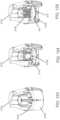
- FIGURE 1shows an exemplary in vivo-based analyte monitoring system 100 in accordance with embodiments of the present disclosure.
- analyte monitoring system 100includes on body electronics 1 100 electrically coupled to in vivo analyte sensor 14 (a proximal portion of which is shown in FIG. 1 , and attached to adhesive layer 218 for attachi-nent on a skin surface on the body of a user.
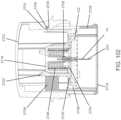
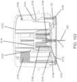
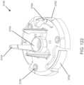
- body electronics 1100includes on body housing 122 that defines an interior compartment.
- insertion device 200(or insertion devices 300, 400, 2400, 2500, 2700, 3700 described herein) that, when operated, transcutaneously positions a portion of analyte sensor 14 through a skin surface and in fluid contact with ISF, and positions on body electronics 1100 and adhesive layer 218 on a skin surface, as will be described in greater detail herein.
- analyte sensor 14 and adhesive layer 218are sealed within the housing of insertion device 200 before use, and in certain embodiments, adhesive layer 218 is also sealed within the housing or the adhesive layer can provide a seal for preserving the sterility of the apparatus. Additional details regarding insertion devices are discussed, e.g., in U.S. Patent Application No.
- analyte monitoring system 100includes display device 1200 which includes a display 1220 to output information to the user, an input component 1210 such as a button, actuator, a touch sensitive switch, a capacitive switch, pressure sensitive switch, jog wheel or the like, to input data or command to display device 1200 or otherwise control the operation of display device 1200.
- display-less devices or deviceswithout any user interface components. These devices may be functionalized to store data as a data logger and/or provide a conduit to transfer data from on body electronics and/or a display-less device to another device and/or location.
- Embodimentswill be described herein as display devices for exemplary purposes which are in no way intended to limit the embodiments of the present disclosure. It will be apparent that display-less devices may also be used in certain embodiments.
- on body electronics 1100may be configured to store some or all of the monitored analyte related data received from analyte sensor 14 in a memory during the monitoring time period, and maintain it in memory until the usage period ends.
- stored datais retrieved from on body electronics 1 100 at the conclusion of the monitoring time period, for example, after removing analyte sensor 14 from the user by detaching on body electronics 1100 from the skin surface where it was positioned during the monitoring time period.
- real time monitored analyte levelis not communicated to display device 1200 during the monitoring period or otherwise transmitted from on body electronics 1100, but rather, retrieved from on body electronics 1100 after the monitoring time period.
- input component 1210 of display device 1200may include a microphone and display device 1200 may include software configured to analyze audio input received from the microphone, such that functions and operation of the display device 1200 may be controlled by voice commands.
- an output component of display device 1200includes a speaker for outputting information as audible signals. Similar voice responsive components such as a speaker, microphone and software routines to generate, process and store voice driven signals may be provided to on body electronics 1100.
- display 1220 and input component 1210may be integrated into a single component, for example a display that can detect the presence and location of a physical contact touch upon the display such as a touch screen user interface.
- the usermay control the operation of display device 1200 by utilizing a set of pre-programmed motion commands, including, but not limited to, single or double tapping the display, dragging a finger or instrument across the display, motioning multiple fingers or instruments toward one another, motioning multiple fingers or instruments away from one another, etc.
- a displayincludes a touch screen having areas of pixels with single or dual function capacitive elements that serve as LCD elements and touch sensors.
- Display device 1200also includes data communication port 1230 for wired data communication with external devices such as remote terminal (personal computer) 1700, for example.
- Example embodiments of the data communication port 1230include USB port, mini USB port, RS-232 port, Ethernet port, Firewire port, or other similar data communication ports configured to connect to the compatible data cables.
- Display device 1200may also include an integrated in vitro glucose meter, including in vitro test strip port 1240 to receive an in vitro glucose test strip for performing in vitro blood glucose measurements.
- display 1220in certain embodiments is configured to display a variety of information - some or all of which may be displayed at the same or different time on display 1220.
- the displayed informationis user-selectable so that a user can customize the information shown on a given display screen.
- Display 1220may include but is not limited to graphical display 1380, for example, providing a graphical output of glucose values over a monitored time period (which may show important markers such as meals, exercise, sleep, heart rate, blood pressure, etc, numerical display 1320, for example, providing monitored glucose values (acquired or received in response to the request for the information), and trend or directional arrow display 1310 that indicates a rate of analyte change and/or a rate of the rate of analyte change, e.g., by moving locations on display 1220.
- graphical display 1380for example, providing a graphical output of glucose values over a monitored time period (which may show important markers such as meals, exercise, sleep, heart rate, blood pressure, etc, numerical display 1320, for example, providing monitored glucose values (acquired or received in response to the request for the information), and trend or directional arrow display 1310 that indicates a rate of analyte change and/or a rate of the rate of analyte change, e.
- display 1220may also include date display 1350 providing for example, date information for the user, time of day information display 1390 providing time of day information to the user, battery level indicator display 1330 which graphically shows the condition of the battery (rechargeable or disposable) of the display device 1200, sensor calibration status icon display 1340 for example, in monitoring systems that require periodic, routine or a predetermined number of user calibration events, notifying the user that the analyte sensor calibration is necessary, audio/vibratory settings icon display 1360 for displaying the status of the audio/vibratory output or alarm state, and wireless connectivity status icon display 1370 that provides indication of wireless communication connection with other devices such as on body electronics, data processing module 1600, and/or remote terminal 1700.
- display 1220may further include simulated touch screen button 1250, 1260 for accessing menus, changing display graph output configurations or otherwise for controlling the operation of display device 1200.
- display 1220 of display device 1200may be additionally, or instead of visual display, configured to output alarms notifications such as alarm and/or alert notifications, glucose values etc, which may be audible, tactile, or any combination thereof.
- the display device 1200may include other output components such as a speaker, vibratory output component and the like to provide audible and/or vibratory output indication to the user in addition. to the visual output indication provided on display 1220. Further details and other display embodiments can be found in, e.g., U.S. Patent Application No. 12/871,901 , U.S. provisional application nos. 61/238,672 , 61/247,541 , 61/297,625 , the disclosures of each of which are incorporated herein by reference for all purposes.
- on body electronics 1100in certain embodiments is configured to wirelessly communicate analyte related data (such as, for example, data corresponding to monitored analyte level and/or monitored temperature data, and/or stored historical analyte related data) when on body electronics 1100 receives a command or request signal from display device 1200.
- analyte related datasuch as, for example, data corresponding to monitored analyte level and/or monitored temperature data, and/or stored historical analyte related data
- on body electronics 1100may be configured to at least periodically broadcast real time data associated with monitored analyte level which is received by display device 1200 when display device 1200 is within communication range of the data broadcast from on body electronics 1100, i.e., it does not need a command or request from a display device to send information.
- display device 1200may be configured to transmit one or more commands to on body electronics 1100 to initiate data transfer, and in response, on body electronics 1100 may be configured to wirelessly transmit stored analyte related data collected during the monitoring time period to display device 1200.
- Display device 1200may in turn be connected to a remote terminal 1700 such as a personal computer and functions as a data conduit to transfer the stored analyte level information from the on body electronics 1100 to remote terminal 1700.
- the received data from the on body electronics 1100may be stored (permanently or temporarily) in one or more memory of the display device 1200.
- display device 1200is configured as a data conduit to pass the data received from on body electronics 1100 to remote terminal 1700 that is connected to display device 1200.
- Remote terminal 1700may include a personal computer, a server terminal a laptop computer or other suitable data processing devices including software for data management and analysis and communication with the components in the analyte monitoring system 1000.
- remote terminal 1700may be connected to a local area network (LAN), a wide area network (WAN), or other data network for uni-directional or bi-directional data communication between remote terminal 1700 and display device 1200 and/or data processing module 1600.
- LANlocal area network
- WANwide area network
- Remote terminal 1700in certain embodiments may include one or more computer terminals located at a physician's office or a hospital.
- remote terminal 1700may be located at a location other than the location of display device 1200.
- Remote terminal 1700 and display device 1200could be in different rooms or different buildings.
- Remote terminal 1700 and display device 1200could be at least about one mile apart, e.g., at least about 100 miles apart, e.g., at least about 1000 miles apart.
- remote terminal 1700could be in the same city as display device 1200, remote terminal 1700 could be in a different city than display device 1200, remote terminal 1700 could be in the same state as display device 1200, remote terminal 1700 could be in a different state than display device 1200, remote terminal 1700 could be in the same country as display device 1200, or remote terminal 1700 could be in a different country than display device 1200, for example.
- a separate, optional data communication/processing devicesuch as data processing module 1600 may be provided in analyte monitoring system 1000.
- Data processing module 1600may include components to communicate using one or more wireless communication protocols such as, for example, but not limited to, infrared (IR) protocol, Bluetooth protocol, Zigbee protocol, and 802.11 wireless LAN protocol. Additional description of communication protocols including those based on Bluetooth protocol and/or Zigbee protocol can be found in U.S. Patent Publication No. 2006/0193375 incorporated herein by reference for all purposes.
- Data processing module 1600may further include communication ports, drivers or connectors to establish wired communication with one or more of display device 1200, on body electronics 1100, or remote terminal 1700 including, for example, but not limited to USB connector and/or USB port, Ethernet connector and/or port, FireWire connector and/or port, or RS-232 port and/or connector.
- data processing module 1600is programmed to transmit a polling or query signal to on body electronics 1100 at a predetermined time interval (e.g., once every minute, once every five minutes, or the like), and in response, receive the monitored analyte level information from on body electronics 1100.
- Data processing module 1600stores in its memory the received analyte level information, and/or relays or retransmits the received information to another device such as display device 1200. More specifically in certain embodiments, data processing module 1600 may be configured as a data relay device to retransmit or pass through the received analyte level data from on body electronics 1100 to display device 1200 or a remote terminal (for example, over a data network such as a cellular or WiFi data network) or both.
- a data networksuch as a cellular or WiFi data network
- on body electronics 1100 and data processing module 1600may be positioned on the skin surface of the user within a predetermined distance of each other (for example, about 1-12 inches, or about 1-10 inches, or about 1-7 inches, or about 1-5 inches) such that periodic communication between on body electronics 1100 and data processing module 1600 is maintained.
- data processing module 1600may be worn on a belt or clothing item of the user, such that the desired distance for communication between the on body electronics 1100 and data processing module 1600 for data communication is maintained.
- the housing of data processing module 1600may be configured to couple to or engage with on body electronics 1100 such that the two devices are combined or integrated as a single assembly and positioned on the skin surface.
- data processing module 1600is detachably engaged or connected to on body electronics 1100 providing additional modularity such that data processing module 1600 may be optionally removed or reattached as desired.
- data processing module 1600is programmed to transmit a command or signal to on body electronics 1100 at a predetermined time interval such as once every minute, or once every 5 minutes or once every 30 minutes or any other suitable or desired programmable time interval to request analyte related data from on body electronics 1100.
- a predetermined time intervalsuch as once every minute, or once every 5 minutes or once every 30 minutes or any other suitable or desired programmable time interval to request analyte related data from on body electronics 1100.
- data processing module 1600receives the requested analyte related data, it stores the received data.
- analyte monitoring system 1000may be configured to receive the continuously monitored analyte related information at the programmed or programmable time interval, which is stored and/or displayed to the user.
- the stored data in data processing module 1600may be subsequently provided or transmitted to display device 1200, remote terminal 1700 or the like for subsequent data analysis such as identifying frequency of periods of glycemic level excursions over the monitored time period, or the frequency of the alarm event occurrence during the monitored time period, for example, to improve therapy related decisions.
- the doctor, healthcare provider or the usermay adjust or recommend modification to the diet, daily habits and routines such as exercise, and the like.
- data processing module 1600transmits a command or signal to on body electronics 1100 to receive the analyte related data in response to a user activation of a switch provided on data processing module 1600 or a user initiated command received from display device 1200.
- data processing module 1600is configured to transmit a command or signal to on body electronics 1100 in response to receiving a user initiated command only after a predetermined time interval has elapsed. For example, in certain embodiments, if the user does not initiate communication within a programmed time period, such as, for example about 5 hours from last communication (or 10 hours from the last communication, or 24 hours from the last communication), the data processing module 1600 may be programmed to automatically transmit a request command or signal to on body electronics 1100.
- data processing module 1600may be programmed to activate an alarm to notify the user that a predetermined time period of time has elapsed since the last communication between the data processing module 1600 and on body electronics 1100.
- users or healthcare providersmay program or configure data processing module 1600 to provide certain compliance with analyte monitoring regimen, so that frequent determination of analyte levels is maintained or performed by the user.
- the one or more output indicationsmay be generated by the control logic or processor of the on body electronics 1100 and output to the user on a user interface of on body electronics 1100 so that corrective action may be timely taken.
- the output indications or alarm datamay be communicated to display device 1200 whose processor, upon detection of the alarm data reception, controls the display 1220 to output one or more notification.
- control logic or microprocessors of on body electronics 1100include software programs to determine future or anticipated analyte levels based on information obtained from analyte sensor 14, e.g ., the current analyte level, the rate of change of the analyte level, the acceleration of the analyte level change, and/or analyte trend information determined based on stored monitored analyte data providing a historical trend or direction of analyte level fluctuation as function time during monitored time period.
- Predictive alarm parametersmay be programmed or programmable in display device 1200, or the on body electronics 1100, or both, and output to the user in advance of anticipating the user's analyte level reaching the future level. This provides the user an opportunity to take timely corrective action.
- Informationsuch as variation or fluctuation of the monitored analyte level as a function of time over the monitored time period providing analyte trend information, for example, may be determined by one or more control logic or microprocessors of display device 1200, data processing module 1600, and/or remote terminal 1700, and/or on body electronics 1100. Such information may be displayed as, for example, a graph (such as a line graph) to indicate to the user the current and/or historical and/or and predicted future analyte levels as measured and predicted by the analyte monitoring system 1000.
- a graphsuch as a line graph
- Such informationmay also be displayed as directional arrows (for example, see trend or directional arrow display 1310) or other icon(s), e.g., the position of which on the screen relative to a reference point indicated whether the analyte level is increasing or decreasing as well as the acceleration or deceleration of the increase or decrease in analyte level.
- This informationmay be utilized by the user to determine any necessary corrective actions to ensure the analyte level remains within an acceptable and/or clinically safe range.
- Visual indicatorsincluding colors, flashing, fading, etc.
- audio indicatorsincluding a change in pitch, volume, or tone of an audio output and/or vibratory or other tactile indicators may also be incorporated into the display of trend data as means of notifying the user of the current level and/or direction and/or rate of change of the monitored analyte level.
- the system 1000may include an algorithm stored on computer readable medium to determine the time it will take to reach a clinically significant level and will output notification in advance of reaching the clinically significant level, e.g., 30 minutes before a clinically significant level is anticipated, and/or 20 minutes, and/or 10 minutes, and/or 5 minutes, and/or 3 minutes, and/or 1 minute, and so on, with outputs increasing in intensity or the like.
- programmed clinically significant glucose threshold levelse.g., hyperglycemic and/or hypoglycemic levels
- current analyte level derived by an in vivo analyte sensorthe system 1000 may include an algorithm stored on computer readable medium to determine the time it will take to reach a clinically significant level and will output notification in advance of reaching the clinically significant level, e.g., 30 minutes before a clinically significant level is anticipated, and/or 20 minutes, and/or 10 minutes, and/or 5 minutes, and/or 3 minutes, and/or 1 minute, and so on, with outputs
- software algorithm(s) for execution by data processing module 1600may be stored in an external memory device such as an SD card, microSD card, compact flash card, XD card, Memory Stick card, Memory Stick Duo card, or USB memory stick/device including executable programs stored in such devices for execution upon connection to the respective one or more of the on body electronics 1100, remote terminal 1700 or display device 1200.
- software algorithms for execution by data processing module 1600may be provided to a communication device such as a mobile telephone including, for example, WiFi or Internet enabled smart phones or personal digital assistants (PDAs) as a downloadable application for execution by the downloading communication device,
- PDAspersonal digital assistants
- PDAsas described above include, for example, portable electronic devices including one or more microprocessors and data communication capability with a user interface (e.g., display/output unit and/or input unit, and configured for performing data processing, data upload/download over the internet, for example,
- remote terminal 1700may be configured to provide the executable application software to the one or more of the communication devices described above when communication between the remote terminal 1700 and the devices are established.
- executable software applicationsmay be provided over-the-air (OTA) as an OTA download such that wired connection to remote terminal 1700 is not necessary.
- OTAover-the-air
- executable applicationsmay be automatically downloaded as software download to the communication device, and depending upon the configuration of the communication device, installed on the device for use automatically, or based on user confirmation or acknowledgement on the communication device to execute the installation of the application.
- the OTA download and installation of softwaremay include software applications and/or routines that are updates or upgrades to the existing functions or features of data processing module 1600 and/or display device 1200.
- new software and/or software updatessuch as software patches or fixes, firmware updates or software driver upgrades, among others, for display device 1200 and/or on body electronics 1100 and/or data processing module 1600 may be provided by remote terminal 1700 when communication between the remote terminal 1700 and display device 1200 and/or data processing module 1600 is established.
- software upgrades, executable programming changes or modification for on body electronics 1100may be received from remote terminal 1700 by one or more of display device 1200 or data processing module 1600, and thereafter, provided to on body electronics 1100 to update its software or programmable functions.
- software received and installed in on body electronics 1100may include software bug fixes, modification to the previously stalled software parameters (modification to analyte related data storage time interval, resetting or adjusting time base or information of on body electronics 1100, modification to the transmitted data type, data transmission sequence, or data storage time period, among others). Additional details describing field upgradability of software of portable electronic devices, and data processing are provided in U.S. Application Nos. 12/698,124 , 12/794,721 , 12/699,653 , and 12/699,844 , and U.S. Provisional Application Nos. 61,359,265 , and 61/325,155 the disclosure of which is incorporated by reference herein for all purposes.
- the analyte sensor 14 of the analyte measurement system 100may be used to monitor levels of a wide variety of analytes.
- Analytes that may be monitoredinclude, for example, acetylcholine, amylase, bilirubin, cholesterol, chorionic gonadotropin, creatine kinase (e.g., CK-MB), creatine, DNA, fructosamine, glucose, glutamine, growth hormones, hormones, ketones, lactate, peroxide, prostate-specific antigen, prothrombin, RNA, thyroid-stimulating hormone, and troponin.
- CK-MBcreatine kinase
- the concentration of drugsmay also be monitored.
- antibioticse.g., gentamicin, vancomycin, and the like
- digitoxindigoxin
- digoxindrugs of abuse
- theophyllinedrugs of abuse
- warfarindrugs
- One or more analytemay be monitored by a given sensor.
- the analytesmay be monitored at the same or different times, which may use the same on body electronics (e.g., simultaneously) or with different on body electronics.
- sensor 14is physically positioned in or on the body of a user whose analyte level is being monitored.
- Sensor 14may be configured to continuously sample the analyte level of the user and convert the sampled analyte level, e.g., glucose concentration into a corresponding data signal, e.g., a current or voltage, for input into on body electronics.
- sensor 14may be configured to sample analyte levels on demand.
- the on body electronicsmay amplify, filter, average, and/or otherwise process signal provided by the sensor.
- sensor 14includes a substrate which is a dielectric, e.g ., a polymer or plastic material, such as polyester or polyamide. In this embodiment, the sensor is constructed so that a portion is positionable beneath skin and a portion is above skin. Accordingly, sensor 14 includes an insertion or internal portion 30 and an external or electrical contact portion 32. In some embodiments, the contact portion 32 includes several conductive contacts 36, 38, and 40 (herein shown as three contacts) for connection to other electronics, e.g., at the on body electronics 1100.
- the contacts provided in this embodimentare for a working electrode, a reference electrode, and a counter electrode.
- two or more working electrodesare provided.
- the operative portions of these electrodesthat is, working electrode, reference electrode, and counter electrode (not individually shown), are provided at the insertion portion, e.g., at the distal end of insertion portion 30, e . g ., portion 34.
- one or more electrodesmay be external to the body, e.g., an external counter electrode.
- the contact and operative portions of the electrodesare connected by circuit traces 42, 44, and 46 running on the surface of the substrate.
- the tracesare provided in channels, or may be embedded within the substrate, or may traverse different sides of the substrate.
- the conductive contacts, conductive traces, and electrodesare fabricated from conductive material, such as platinum, palladium, gold, carbon, or the like. More than one material may be used for a given sensor. Further details of sensors are described, e.g., in U.S. Patent Nos. 6,175,572 and 6,103,033 , which are incorporated by reference herein for all purposes.
- Sensor 14may include a proximal retention portion 48.
- the insertion portion 30 and the proximal retention portion 48are sized and configured to be positioned with a sharp for installation into the skin of a subject, as described herein.
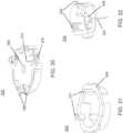
- the sensor 14may be configured to bend (e.g., along the line B) and therefore be positioned in two substantially perpendicular, intersecting planes. Such bending may occur prior to or during coupling to the on body electronics as described below. (See FIGURE 17 ).
- Portions 48 and 52which provide a path for electrical connections, e.g ., the conductive traces, between the proximal and distal portions of the sensor.
- Sensor 14is further provided with a notch or cut-out 54.
- Such configurationfacilitates the sensor 14 to bend (e.g., along the line indicated by line B) such that retention portion 48 remains upright and therefore be positioned in two substantially perpendicular, intersecting planes, as illustrated in FIGURE 3 .
- the sensor tab 50can be encased in the on body housing 122 to aid in securing and positioning the sensor 14.
- Proximal retention portion 48maintains its longitudinal alignment with insertion portion 30 for positioning within an insertion sharp.
- Embodiments of analyte sensorshave been described herein to operate electrochemically, through an arrangement of electrodes having chemical sensing layers applied thereto, by generating an electrical current proportional to the volume of a redox reaction of the analyte (and indicative of analyte concentration), catalyzed by an analyte-specific oxidizing enzyme.
- Embodimentsexist in which the number of electrodes provided to bring about and detect the level of these reactions is two, three, or a greater number.
- other types of sensorsmay be employed as described herein.
- a portion of sensor 14may be situated above the surface of the skin, with a distal portion 30 penetrating through the skin and into the subcutaneous space in contact with the user's biofluid, such as ISF. Further details regarding the electrochemistry of sensor 14 is provided in U.S. Patent Nos. 5,264,104 ; 5,356,786 ; 5,262,035 ; 5,320,725 ; and 6,990,366 , each of which is incorporated by reference herein for all purposes.
- the senoris implantable into a subject's body for a usage period (e.g ., a minute or more, at least one day or more, about one to about 30 days or even longer, about three to about fourteen days, about three to about seven days, or in some embodiments, longer periods of up to several weeks) to contact and monitor an analyte present in a biological fluid.
- a usage periode.g ., a minute or more, at least one day or more, about one to about 30 days or even longer, about three to about fourteen days, about three to about seven days, or in some embodiments, longer periods of up to several weeks
- the sensorcan be disposed in a subject at a variety of sites (e.g., abdomen, upper arm, thigh, etc.), including intramuscularly, transcutaneously, intravascularly, or in a body cavity.
- sensor 14is employed by insertion and/or implantation into a user's body for some usage period.
- the substratemay be formed from a relatively flexible material.
- FIGURES 2-3have three electrodes, other embodiments can include a fewer or greater number of electrodes.
- a two-electrode sensorcan be utilized.
- the sensor 14may be externally-powered and allow a current to pass which current is proportional to the amount of analyte present.
- the sensor 14itself may act as a current source in some embodiments.
- the sensormay be self-biasing and there may be no need for a reference electrode.
- An exemplary self-powered, two-electrode sensoris described in U.S. Patent Application Serial No.
- the level of current provided by a self-powered sensormay be low, for example, on the order of nanoamperes, in certain embodiments.
- an insertion assemblyincludes an inserter and the medical device itself.
- the insertercan be configured to insert various medical devices into the subject, such as for example, an analyte sensor, an infusion set, or a cannula.
- the insertercan be configured to install a combination of such devices, e.g., a combined sensor/infusion set, etc., at the same or different times or locations.
- a given insertercan be configured to install a first device and a second device at different times. In this regard, the inserter can be reusable.
- an insertermay be modifiable to be used with more than one medical device, to include more than one type of medical device, e.g ., by attaching an adapter and/or removing detaching a portion of an inserter.
- the insertercan install the medical device in, under, or through the skin of the subject, or place the medical device on the surface of the skin.
- the medical devicecan include features or structures, e.g., barbs, tabs, adhesive, etc., to maintain the device in position with respect to the skin after insertion.
- the inserter devicemay also be used as a lancet, e.g., to pierce the skin without inserting or installing a medical device.
- an insertion assemblyincludes an inserter, an analyte sensor, and a power supply.
- the power supplymay be applied to the patient, e.g., to the surface of the skin, simultaneously with the analyte sensor by the inserter,
- the batteryis installed after or before installation of the analyte sensor.
- the power supplymay be applied by the inserter or separately.
- the power supplymay be used to provide a current or a potential to the sensor and/or to provide power for communication of one or more signals to the monitor unit.
- an insertion assemblyincludes an inserter, a medical device such as an analyte sensor, and on body electronics.
- the on body electronicsmay be deployed and/or installed simultaneously with the analyte sensor by the inserter.
- the on body electronicsare installed after or before installation of the analyte sensor.
- the analyte sensormay be installed by the inserter, and the on body electronics may be subsequently installed.
- the on body electronicsprovide a voltage or current to the analyte sensor.
- the on body electronicsprocess signals provided by the analyte sensor.
- the on body electronicsmay include communications functionality for providing signal relating to signal provided by the analyte sensor to a further component, such as, e.g., a monitor unit, a computer, or other component.
- communications circuitrysuch as an RFID antenna, is provided. The power supply may be used to power some or all of these functions. In some embodiments, power is provided from the monitor unit, e.g., via inductive coupling.
- An insertercan include a plurality of different components.
- an insertermay include one or more components for advancing a sharp towards the skin of the subject.
- the sensor and on body electronicsmay be supported by a support structure, such as a carriage.
- a drivermay be provided for advancing the sharp and/or the analyte sensor/support structure towards the skin of the patient.
- the actuatoris directly or indirectly coupled to the sharp and/or support structure, such that manual force applied by the user to the actuator is transferred to the sharp and/or support structure.
- the applied forcedrives the sharp and/or support structure between a retracted position (disposed within the insertion device) and an advanced position (disposed towards the skin of the patient).
- the senor and on body electronicsis maintained in a retracted position prior to installation by contacting projections extending inwardly from a recess in the inserter.
- the sensor and on body electronicsare temporarily maintained operatively between the support structure and the projections disposed on the interior wall of the sheath .
- An insertercan also include one or more components for retracting the sharp, while allowing the analyte sensor and optional on body electronics to remain on the subject.
- the components for retracting the sharpcan include a retractor. It is understood that the retractor and the actuator may be the same structure or include some common components.
- the retractoris directly or indirectly coupled to the sharp such that the manual force applied by the user is transferred from the retractor to the sharp to retract the sharp from the skin.
- a drive assemblymay be provided to retract the sharp.
- the drive assemblymay include a spring, motor, hydraulic piston, etc., to retract the sharp away from the skin of the subject.
- the drive assemblymay also include a linear drive component.
- the retractorwithdraws the sharp upon actuation by the user.
- the useractuates the retractor when it is desired to withdraw the sharp.
- the retractormay include a release switch.
- the drive assemblye.g., the spring or other driver, retracts the sharp from the skin.
- the retractor and the actuatorinclude common components. After activating the actuator to advance the sharp and the analyte sensor, the user releases the actuator, which allows the drive assembly to withdraw the sharp from the skin.
- the retractorwithdraws the sharp without further user interaction after actuation of insertion.
- the insertermay include features or components which automatically retract the sharp upon advancement of the sharp and support structure by a predetermined amount. Inserter devices, in which no further action by the user is required to initiate withdrawal of the sharp after insertion, are referred to herein as having "automatic" withdrawal of the sharp.
- Inserter 200in accordance with an exemplary embodiment is illustrated in FIGURE 4 .
- Inserter 200includes a housing 202 and a removable distal cap 204 for maintaining a sterile environment for the medical device and sharp housed therein.
- inserter 200has a maximum diameter, of about 30mm to about 60 mm, e.g., about 40 mm, about 43 mm, about 43.5 mm, about 50.5 mm, about 54.5 mm, etc.
- inserter 200has a maximum height of about 40 mm to about 80 mm, e.g., about 44 mm, about 46 mm, about 50 mm, about 53 mm, about 67 mm, about 71 mm, etc.
- inserter 200has a volume of about 35 cm 3 to about 110 cm 3 , e.g., about 40 cm 3 , about 41 cm 3 , about 50 cm 3 , about 60 cm 3 , about 61 cm 3 , about 62 cm 3 , about 69 cm 3 , about 70 cm 3 , about 79 cm 3 , about 90 cm 3 , about 106 cm 3 , etc.
- the dimensionare defined with respect to the housing 202.
- Housing 202 and distal cap 204may be fabricated from any suitable materials such as metal, plastic, etc.
- cap 204may be fabricated from a polymer or plastic material.
- a removable proximal cover 206which, among other things, prevents accidental deployment of the inserter 200 and maintains a sterile environment.
- proximal cover 206is a sheet of material such as a foil sheet or the like secured to the upper surface of housing 202 using an adhesive, and may include a tab 208 to assist removal of the cover 206.
- Proximal cover 206may also be a plastic sheet or member that forms a seal with housing 202.
- proximal cover 206may include a pull tab or a perforated section for easy removal.
- proximal cover 206 and distal cap 204are shown removed from inserter 200.
- Distal cap 204is secured to housing 202, e.g., by use of threads 210.
- distal cap 204is secured by a friction fit, snap fit, a bayonet mount, an adhesive, etc.
- the distal portion of cap 204may include a recess for retaining a desiccant therein.
- a silica gel or molecular sievesmay be used. Such material can be in granular form (pellets) or pressed into tablets, or otherwise. In some embodiments, silica gel tablets are used.
- Embodimentsmay include desiccant and/or packaging as described in U.S. Patent Application Serial No. 12/714,439 , which is incorporated by reference herein for all purposes.
- Cap 204may be provided with one or more apertures, which allows for passage of air to the desiccant to remove moisture from the interior of the inserter 200.
- Housing 202includes a distal portion 212 for placement on the skin of a subject.
- Inserter 200includes an actuator 214 to advance a medical device into the skin of the subject.
- actuator 214is disposed within an opening 216 in housing 202 and can be longitudinally moveable within housing 202.
- inserter 200supports a medical device, such as on body housing 122 (not shown) and a sharp 224.
- body housing 122includes an analyte sensor 14. During insertion, sharp 224 passes through aperture 220 and into the skin of the subject carrying at least the sensor 14 with it.
- FIGURE 7illustrates inserter 200 in cross-section, in an initial configuration prior to use, after removal of the distal cap 204.
- Actuator 214may be cylindrical in shape (or other shape as appropriate) and, including an upper contact surface 226, capable of being depressed by a user and/or a mechanism, as described herein. Actuator 214 may further include side walls 228 extending downwardly from upper surface 226, and which engage or otherwise contact the upper surface of carriage 230.
- Carriage 230provides a support for holding the medical device, such as on body housing 122, prior to and during installation.
- carriage 230includes a distal portion 232, which may be configured to form a substantially concave recess 232a as shown in this embodiment, for supporting the medical device therein.
- the on body housing 122is supported within the recess 232a of carriage 230 in a snap-fit or other relationship.
- carriage 230does not include a recess.
- carriagemay include one or more projections which contact and/or advance the on body housing 122. (See, e.g., FIGURES 122 , 135-136 herein.)
- FIGURE 8the longitudinal axis L of the inserter 200 is illustrated.
- a support member 234Extending distally from the upper surface 226 of actuator 214 and substantially parallel to the longitudinal axis is a support member 234, which may have an elongated configuration.
- Support member 234supports needle hub 236, from which sharp 224 extends longitudinally within the inserter 200.
- the sharp 224is supported at an oblique angle, e.g., between about 0° and 90° with respect to the skin surface.
- Needle hub 236can be secured to support member 234 via an interlocking O-ring configuration, adhesive, or other techniques known in the art.
- Support member 234can be omitted and needle hub 236 can be secured to the actuator 214 directly in some embodiments, e.g., by manufacturing needle hub 236 as a single component with actuator 226 or by otherwise adhering needle hub 236 to actuator 226.
- sharp 224is a solid needle, for example, if inserter 200 is used to insert a cannula.
- sharp 224is provided with a substantially cylindrical configuration defining an interior bore, e.g., a rigid cylindrical member or a hypodermic-style needle.
- Sharp 224may also be provided with an elongated longitudinal opening or gap in the wall of the sharp 224 (see, sharp 224 in FIGURES 11-18 ).
- sharp 224is fabricated from a sheet of metal, and folded into a substantially "V" or "U” or “C” configuration in cross-section to define the longitudinal recess.
- Needle hub 236is further illustrated in FIGURES 9-10 .
- Needle hub 236supports sharp 224, having a sharpened distal portion 260.
- a longitudinal wall opening or gap 262is provided in at least a portion of the wall of the sharp 224.
- the length N of the gap 262is selected to be commensurate with the length of the insertion portion 30 through to the proximal retention portion 48 of the sensor 14 where the bend at line B occurs (See FIGURES 2-3 ), and in certain embodiments may be about 3 mm to about 50 mm, e.g., about 5 mm, or about 10 mm, or about 15 mm, or about 20 mm.
- the length L of the sharp 224may be about 3 mm to about 50 mm, e.g., 5mm or more, or about 10 mm, or about 20 mm, or about 30 mm, or about 50 mm, and is selected based upon the length of the insertion portion 30 of a sensor and the desired depth of the insertion portion 30 of the sensor 14. In some embodiments, the distance or spacing between the two edges of the gap is about 0.2mm to about 0.5mm, e.g ., about 0.22mm, about 0.25mm, etc. (See, spacing 257 in FIG. 11 ).
- sharp 224has a substantially "C"- or “U”-shaped profile in this embodiment, but may have other configurations, e.g., substantially “V”-shaped.
- a longitudinal gap 262is provided in the wall of the sharp 224.
- FIGURE 12illustrates distal portion 260 is provided with an angled tip.
- the angled tipmay be provided with a first angled tip portion 264 and a second steep-angled tip portion 266.
- the exemplary configurationwhich includes multiple edges and faces, provides a sharp point to reduce penetration force, trauma, and bleeding for the subject.
- the distal section of the sensor bodyhas a width sized to fit within the gap 262 of the insertion sharp 224 having a diameter less than about 20 to about 26 gauge, e.g., 21 gauge to about 25 gauge, where in certain embodiments the sharp is 21 gauge or 23 gauge or 25 gauge.
- Such sharpmay be used with a sensor having a width or diameter - at least the portion that is carried by the sharp — of about .20 mm to about .80 mm, e.g., about .25 mm to about .60 mm, where in some embodiments the width or diameter of at least a portion of a sensor is .27 mm or .33 mm or .58 mm.
- sharp 224is fabricated from a sheet of metal and folded into a substantially "V" or "U” or "C" configuration in cross-section.
- a folded sheet of metal to form sharp 224can be used to manufacture a folded sheet of metal to form sharp 224.
- etched-sheet metal technologycan be used to form the sharp 224.
- the sharpcan be formed having a very sharp edge so that penetration through the skin during insertion is less painful.
- a progressive die technologymay be utilized to form a complex sheet-metal shape that has a sharp edge as depicted in FIGURE 14 .
- the sharp 224can be molded with a plastic cap so that the sharp can be handled during the inserter assembly process. Further, the die cut sharp may be molded with plastic to reinforce the "V,” "U,” or "C" shaped sheet metal configuration.
- a "U" shaped cross-sectioncan be provided with having flat, rather than curved walls.
- the "U” shaped configurationprovides the advantage that they can more securely and closely hold the sensor.
- the "U” shaped configurationprovides the advantage that it has a reduced cross-section when compared with a comparable circular cross section.
- FIGURES 14A-CFurther details of the tip of sharp 224 are illustrated in FIGURES 14A-C .
- a top view of the sharp 224is shown. This represents a flat portion of the sharp, e.g., the bottom of the "U” configuration.
- a tipis formed by first distal edges 263 closest to the distal tip and second distal edges 265 between the first distal edges 263 and the substantially parallel side walls 269.
- the first distal edges 163form an "included tip” angle of about 15 degrees, about 30 degrees, or about 60 degrees. Such angle is symmetrical, that is, equal angles from the longitudinal axis of the sharp 224.
- the second distal edges 265provide a somewhat less acute angle than the first distal edges 263.
- the "lead in" anglemay be about 20 degree, about 45 degrees, or about 65 degrees.
- Figure 14Cillustrates a side view of the sharp 224 and illustrates the side walls 269.
- An additional angle, i.e., the "lead-out" angleis provided by the rising edge 267 of the sharp.
- the edge 267provides the ability to separate the tissue to allow placement of the sensor 14.
- a lasercut sharpcan be formed. In this manner, the laser can be used to form the wall opening or gap 262 and first-angled tip portion 264 and a second, steep-angled tip portion 266.
- sharp 224may be formed from a standard hypodermic needle utilizing the method depicted in FIGURE 15 .
- the hypodermic needle(having a circular cross-section) is cut to the desired length for sharp 224.
- the hypodermic needleis compressed so that its cross-section is permanently deformed from a circular shape to an oval shape.
- the tip of the hypodermic needleis then ground to a bevel to produce a sharp point to reduce the required penetration force, as previously discussed.
- the top section of the needleis removed by appropriate techniques (e.g., grinding, electropolish, etc.).
- the resulting sharp 224has a "U"-shaped configuration and provides ample space for the insertion of sensor 14.
- the tip-grinding step and the compression stepmay be carried out in reversed order.
- a usermay initially start with a larger diameter hypodermic needle so that the finished sharp 224 will have similar dimensions to the previously described sharps.
- FIGURES 16-18illustrate the position of on body housing 122 with respect to the needle hub 236 and sharp 224.
- the on body housing 122can be configured to hold at least a portion of sensor 14 and on body electronics 1100 (also referred to herein as electronics 80).
- the sharp 224extends through an aperture 168 in the on body housing 122.
- the sharp 224is uncoupled to on body housing 122.
- the distal portion of sensor 14is positioned within the sharp 224.
- on body electronics 1100 and sensor hub 123are positioned within on body housing 122.
- Sensor 14may include an optional positioning structure, or slit 127, which receives a positioning member, such as tab 129 of sensor hub 123.
- a power supply 82such as a battery, e.g., a single use disposable battery, or rechargeable battery, is optionally provided.
- FIGURE 17Aillustrates a detail of sensor hub 123, which includes an aperture 190 through which sharp 224 and sensor 14 are configured to pass through.
- aperture 190is provided with an additional side channel 192 continuous with the aperture 190.
- Side channel 192is positioned in the location in which the pointed tip 260 of the sharp 224 would first pass through the aperture.
- the tip 260passes through the aperture without contacting the sensor hub 123.
- the tip 160makes contact with the sensor hub 123 and may be damaged and/or it may become jammed or otherwise unable to pass through the aperture.
- the side channel 192provides additional clearance for the tip 160 to pass through the aperture undamaged.
- FIGURE 18illustrates in cross-section the orientation of the on body housing 122 with respect to the sharp 224 of inserter 200.
- sensor 14is disposed in a substantially bent configuration in some embodiments, such that a portion of the sensor, e.g., the insertion portion 30 and the proximal retention portion 48, are substantially vertical (e.g., substantially aligned with the longitudinal axis of the inserter 200 and substantially perpendicular to the skin surface) and the contact portion 32 (shown in profile) is oriented in a substantially horizontal configuration, and in electrical contact with on body electronics 1100.
- the sensor tab 50can be encapsulated in the plastic of the on body housing 122 and secured in place.
- the notch 56provides further stability to the sensor 14, e.g., by allowing the sensor tab 50 to be encased by the material of the on body housing 122, and further provides a means for vertically orienting the sensor 14 during mounting, e.g., by allowing vertical positioning of the notch 56 with respect the on body housing 122.
- the sensor 14, mounted with the on body housing 122can be disposed within a recess of the carriage 230 such as a concave recess in the carriage 230.
- the sensor 14, mounted with the on body housing 122can be disposed between the support structure and one or more projections extending from the wall of the sheath 242 (not shown).
- the sensor 14 mounted with the on body housing 122can be held in position by a releasable friction fit coupling to the sharp 224. In this manner, the carriage need not have a recess within which the sensor mounted with the on body housing is disposed.
- the sharp 224extends through a longitudinal aperture 268 formed in a carriage 230.
- the aperture 268is appropriately sized, such that neither the sharp 224 nor needle hub 236 is in contact with the carriage 230. Accordingly, the needle hub 236 (and sharp 224) on the one hand, and the carriage 230 and the on body housing 122, on the other hand, move simultaneously but independently from one another. In other embodiments, a friction fit may be provided between the aperture and the sharp.
- the insertion portion 30 and proximal retention portion 48 of the sensor 14are disposed within a longitudinal bore 162 within the sharp 224 (See, e.g., FIGURE 7 ).
- the proximal retention portion 48is disposed within the longitudinal bore of the sharp 224 and provides additional stability to the mounting of the sensor 14 within the sharp 224.
- the longitudinal wall gap or opening 262 of sharp 224is aligned with the sensor 14, such that the tab 50 and the contact portion 32 extend laterally outward from the sharp 224.
- a resilient member 70may be included to provide frictional contact with the sharp 224 and/or the sensor 14. Such frictional contact provides additional stability between the on body housing 122 and sharp 224, as depicted in FIGURES 19-21 .
- resilient member 70may be formed as a spherical, ovoid, cylindrical, cube-shaped member, etc.
- Resilient member 70may be formed from any elastomeric material, e.g., molded plastic components, rubber, nitrile, viton, urethane, etc.
- resilient member 70is press-fit into a recess, such as an eccentric bore 72 located in on body housing 122 ( FIGURE 21 ). When sharp 224 is inserted within an aperture in the on body housing 122, the resilient member 70 exerts a pressure on sharp 124 and sensor 14 to hold them firmly in groove 74.
- groove 74is a V-shape. Alternatively, groove 74 may be U-shaped depending on the configuration of sensor 14 and sharp 224.
- resilient member 70is provided with a flattened or recessed surface which abuts sharp 224.
- the sensor 14, mounted with the on body housing 122,is carried by the carriage, e.g., disposed within the concave recess 232a in the carriage 230, as described hereinabove (see, e.g., FIGURES 16-21 ).
- the sharp 224extends through a longitudinal aperture formed in the carriage 230.
- the apertureis appropriately sized, such that neither the sharp 224 nor needle hub 236 is in contact with the carriage 230.
- a clearancemay be provided between the surfaces of the carriage and the sharp and needle hub.
- sharp 224is capable of substantial lateral movement or "play" with respect to aperture. Accordingly, the needle hub 236 (and sharp 224) on the one hand, and the carriage 230 and the on body housing 122, on the other hand, can move simultaneously but independently from one another.
- the insertion portion 30 and proximal retention portion 48 of the sensor 14are disposed within a longitudinal bore of the sharp 224.
- the proximal retention portion 48is disposed within the longitudinal bore 225 of the sharp 224 and provides additional stability to the disposition of the sensor 14 within longitudinal bore 225 of the sharp 224.
- the longitudinal wall gap of sharp 224is aligned with the sensor 14, such that the tab 50 and the contact portion 32 extend laterally outward from the sharp 224.
- an optional sheath 242is positioned within housing 202, having an annular configuration and including a circumferential recess 244 in which a retraction spring 246 is positioned.
- the distal portion of spring 246contacts a spring retention portion 248 in sheath 242.
- the proximal portion of spring 246contacts one or more tabs 250 extending laterally outwardly from actuator 214.
- the spring 246may be in a semi-compressed state, i.e ., not fully compressed, nor fully extended.
- sheath 242may be omitted from inserter 200, and a recess, such as recess 244, provided within housing 202.
- recess 244may be omitted entirely, and spring 246 or other actuator may be disposed between stops in housing 202.
- Depression of the actuator 214causes distal longitudinal movement of the carriage 230 and sharp 224, from a proximal position (space apart from the skin of the subject) to a distal position (closer to the skin of the subject). During such downward, distal movement, spring 246 is further compressed between spring retention portion 248 and flanges 250.
- depression of the contact surface 226moves the actuator side walls 228 and the tabs 250 downwardly distally against the bias of spring 246.
- Contact of the side wall 228 of the actuator 214 with the upper surface of the carriage 230 during depression of the actuator 214imposes a downward force and consequential distal movement of the carriage 230.
- the sharp 224is urged distally, it carries the sensor insertion portion 30 into the subcutaneous portion of the subject's skin S.
- flanges 270are disposed in the inner wall of sheath 242.
- the flanges 270engage the proximal (upper) surface of the carriage 230, and thereby inhibit proximal movement of the carriage 230 (see also FIGURE 24 ).
- the distal (lower) surface of the on body housing 122engages the upper surface of adhesive pad 218, thereby becoming adhered to the skin surface S of the subject
- the flanges 270also engage fingers 274 disposed on the proximal face of the carriage 230. Fingers 274 are pivoted inwards by flanges 270.
- fingers 274Such pivoting of fingers 274 causes fingers 274 to become disengaged from retention tab 250 on actuator 214.
- Spring 246is thereby permitted to decompress and expand, and thereby provide an upward force on actuator 214. If the user or some apparatus provides no downward force, or minimal downward force to overcome the bias of spring 246, the actuator 214, along with needle hub 236 and sharp 224 move proximally, withdrawing the sharp 224 from the skin S of the subject.
- the actuator 214 and coupled sharp 224advances to a more proximal position than at the initial configuration illustrated in FIGURES 5 and 7 due to the decoupling of actuator 214 from carrier 30.
- the sharp 224retracts from a distal position to a proximal position after installation of the on body housing 122 and insertion of at least a portion of the sensor.
- inserter 300has a maximum diameter of about 30mm to about 60 mm, e.g., about 40 mm, about 43 mm, about 43.5 mm, about 50.5 mm, about 54.5 mm, etc.
- inserter 300has a maximum height of about 40 mm to about 80 mm, e.g ., about 44 mm, about 46 mm, about 50 mm, about 53 mm, about 67 mm, about 71 mm, etc. Such height is defined by the total length of the housing 302 and the sheath 342.
- inserter 300has a volume of about 35 cm 3 to about 110 cm 3 , e.g., about 40 cm 3 , about 41 cm 3 , about 50 cm 3 , about 60 cm 3 , about 61 cm 3 , about 62 cm 3 , about 69 cm 3 , about 70 cm 3 , about 79 cm 3 , about 90 cm 3 , about 106 cm 3 , etc.
- Such dimensionsare defined by the total length of the housing 302 and the sheath 342.
- inserter 300in certain embodiments includes, e.g., a handle 302, a sheath 342, and a removable distal cap 304 for maintaining a sterile environment for the medical device and sharp housed therein.
- FIGURE 26illustrates that distal cap 304 is removed from handle 302.
- Distal cap 304is secured to handle 302 by one of a number of securement means, e.g., by use of threads 310.
- Sheath 342defines a distal surface 312 for placement on the skin of a subject.
- Inserter 300may be utilized to advance a medical device into the skin of the subject.
- handle 302is advanced relative to sheath 342 in order to advance the medical device into the skin of the patient.
- handle 302may include threads 310 for attachment of cap 304 via threads 311 (as illustrated in FIGURE 29 ). It is understood that other securement techniques, such as a snap-fit or friction-fit may be used to secure cap 304.
- Cap 304may include a receptacle 325 for positioning of the sharp 324.
- Sheath 342, as illustrated in FIGURE 28includes longitudinal notches 382.
- Projections 386 on carriage 330are configured to engage sheath to secure carriage 330 within the inserter 300, thereby preventing release of the carriage 330 from the inserter 300.
- Projections 375engage with the triangular latch features 370 of the sheath 342 as illustrated in FIGURES 34 and 36 .
- Carriage 330also is provided with fingers 375 which engage a shoulder wall 376 of sharp 334 (as illustrated in FIGURE 34 ), as will be described in greater detail herein.
- inserter 300also includes a spring retention component 348, as illustrated in FIGURE 31 .
- Spring retention component 348defines an upper surface 349, which engages spring 346 (as illustrated in FIGURE 34 ).
- Spring retention component 348also includes locking towers 351 including projections, which engage apertures 328 of needle carrier 334 to prevent accidental deployment of the sharp 324 after use of the inserter 300 is completed.
- Inserter 300is illustrated in cross-section in FIGURE 33 prior to use.
- Cap 304is attached to the distal portion of inserter 300, via securement means, such as inter-engagement of threads 310 and 311.
- Cap 304includes a desiccant tablet 390; a seal, such as a foil seal 392; and a Tyvek ® layer 394, which allows breathability between the desiccant tablet 390 and the interior of the inserter 300.
- the inserter 300includes an initial configuration in which the handle 302 is disposed in a proximal position with respect to the sheath 342. In such configuration, the sharp 324 is disposed in a configuration spaced apart from the aperture 320 of the adhesive layer 318. The distal portion of inserter 300 is illustrated in FIGURE 35 .
- the longitudinal axis L of the inserter 300is illustrated. Extending distally from the upper surface of handle 302 is an inner wall portion 326 and intermediate wall portion 374. Support member 334 extends from wall portion 326 and supports needle hub 336, from which sharp 324 extends longitudinally within the inserter 300. In some embodiments, the sharp is supported at an oblique angle, e.g ., between 0° and 90° with respect to the skin surface.
- Sheath 342is positioned within handle 302, having an annular configuration in which a retraction spring 346 is positioned.
- the distal portion of spring 346contacts a surface 349 of spring retention component 348.
- the proximal portion of spring 346contacts the inner surface 350 of handle 302. In the initial configuration, the spring 346 is in an extended or semi-extended configuration.
- FIGURE 36illustrates inserter 300 in cross-section, during insertion.
- Depression of handle 302 with respect to sheath 342 against the bias of spring 346causes distal longitudinal movement of the carriage 330 and sharp 324, from a proximal position towards a distal position.
- spring 346is compressed between surface 349 of spring retention component 348 and surface 350 of handle 302.
- the sharp 324is urged distally by housing 302, it carries the sensor insertion portion 30 of sensor 14 into the subject's skin S.
- handle 302along with needle hub 336 and sharp 324 are permitted to move proximally, while the sheath 342 and on body housing 122 remain adjacent to the skin of the subject. If the user or some apparatus provides no downward force, or minimal downward force to the handle 302 to overcome the bias of spring 346, spring 346 is permitted to expand, thereby withdrawing the sharp 324 from the skin S of the subject.
- flanges 328 on needle carrier 334engage locking towers 351 of needle floor component 348.
- the inter-engagement of flanges 328 and locking towers 351prevents inadvertent deployment of sharp 324 after installation of the medical device.
- inserter 400has a maximum diameter of about 30mm to about 60 mm, e.g., about 40 mm, about 43 mm, about 43.5 mm, about 50.5 mm, about 54.5 mm, etc. In some embodiments, inserter 400 has a maximum height of about 40 mm to about 80 mm, e.g., about 44 mm, about 46 mm, about 50 mm, about 53 mm, about 67 mm, about 71 mm, etc.
- inserter 400has a volume of about 35 cm 3 to about 110 cm 3 , e.g., about 40 cm 3 , about 41 cm 3 , about 50 cm 3 , about 60 cm 3 , about 61 cm 3 , about 62 cm 3 , about 69 cm 3 , about 70 cm 3 , about 79 cm 3 , about 90 cm 3 , about 106 cm 3 , etc.
- the maximum heightis measured from the top of the housing 402 to the distal surface 412.
- the volumeis measured as the combined volume of the housing 402 and the sheath 442 in an expanded position.
- Inserter 400generally includes, e.g., a handle 402, sheath 442, and a removable distal cap 404 for maintaining a sterile environment for the medical device and sharp housed therein. As illustrated in FIGURE 41 , distal cap 404 is shown removed from handle 402. Distal cap 404 is detachably secured to handle 402, e.g., by use of threads 410. Sheath 442 includes a distal surface 412 for placement on the skin of a subject. Inserter 400 may be utilized to advance a medical device into the skin of the subject. In some embodiments, handle 402 is advanced relative to sheath 442 in order to advance the medical device distally and into the skin of the patient.
- inserter 400The components of inserter 400 are illustrated in FIGURES 42-46 .
- handle 402includes threads 410 for attachment of cap 404 via threads 411 (as illustrated in FIGURE 44 ).
- Cap 404may include a receptacle 425 for positioning of the sharp 424.
- Sheath 442, as illustrated in FIGURE 43includes longitudinal notches 482. Projections 486 on carriage 430, as illustrated in FIGURE 45 , are configured to engage sheath 442 to secure carriage 430 within inserter 400, thereby preventing release of the carriage from the inserter.
- Sheath 442also includes notches 484 which receive projection 475 of carriage 430. The bottom of the notches acts as the retention portion that prevents the carriage 430 from falling out of the inserter 400.
- Projections 475engage with the latch features 470 of the sheath 442 as illustrated in FIGURES 49 and 50 .
- Carriage 430also is provided with fingers 474 which engages a shoulder wall 476 of needle carrier 436, as illustrated in FIGURES 48-49 , and as will be described in greater detail herein.
- Sheath 442also includes a spring retention portion 448, provided at the distal end of circumferential notch 496, as illustrated in FIGURE 48 .
- Needle carrier 434as illustrated in FIGURE 46 , includes wings 450, which provide an upper engagement surface for spring 446. Wings 450 also include a shoulder 476 for engagement with fingers 474 of carriage 430.
- Inserter 400is illustrated in cross-section in FIGURE 47 in a state prior to use and prior to removal of cap 404, which is shown attached to the distal portion of handle 402, via inter-engagement of threads 410 and 411.
- Cap 404includes a desiccant tablet 490, a seal such as a foil seal 492, and a Tyvek ® layer 494, which allows breathability between the desiccant tablet 490 and the interior of the inserter 400.
- the inserter 400is shown in an initial configuration in which handle 402 is disposed in a proximal position with respect to the sheath 442.
- the sharp 424is disposed in a configuration spaced apart from the aperture 420 of the adhesive layer 418.
- the longitudinal axis L of the inserter 400is illustrated.
- Extending distally from the upper surface of handle 402is inner wall 475.
- the distal end portions of wall 475provide a downward force on the carriage 430 upon depression of the handle 402 by a user.
- the carriagecan include one or more upwardly extending walls or projections (not shown).
- the one or more upwardly extending inner walls or projectionscan have a length sufficient to either contact the upper surface of 402 or, alternatively, contact corresponding downwardly extending inner walls of the handle 402. In this manner, depression of handle 402 by a user provides a downward force on the one or more upwardly extending walls or projections of the carriage to advance the carriage (and on-body unit) distally to an installation and insertion position.
- a downwardly extending wall of the handle 402 and a corresponding upwardly extending wall of the carriageare aligned such that depression of the handle 402 by a user allows the upwardly extending wall and the downwardly extending wall to make direct contact, thereby permitting the carriage 430 and on-body unit to advance distally.
- the downwardly extending inner wall of the handlehas a distal end that is disposed proximally of the proximal most end of sheath 442.
- Needle carrier 434can be axially moveable within handle 402. Needle carrier 434 supports needle hub 436, from which sharp 424 extends longitudinally within inserter 400. In some embodiments, sharp 424 is supported at an oblique angle, e.g., between and including about 0° and 90° with respect to the skin surface.
- needle carrier 434is coupled to carriage 430 via inter-engagement of fingers 474 of carriage 430 with shoulder 476 of needle carrier 434.
- Spring 446is disposed between spring retention portion 448 of sheath 442 and wings 450 ( FIGURE 46 ) of needle carrier 434. Initially, spring 446 is in an expanded or semi-expanded state while handle 402 is disposed proximally from sheath 442.
- needle carrier 434can be secured to handle 402, for example, secured to downwardly extending inner wall 475.
- needle carrier and carriage 430are longitudinally moveable along the line defined by L shown in FIGURE 48 with respect to sheath 442.
- needle carrier 434includes one or more apertures to receive one or more downwardly extending inner walls 475 of handle 402.
- neither the needle carrier 434 nor the carriage 430are in slidable contact with sheath 442, e.g., spaced apart from sheath 442, during longitudinal movement of the needle carrier 434 and/or carriage 430.
- FIGURE 49illustrates inserter 400 in cross-section, during insertion. Depression of handle 402 with respect to sheath 442, against the bias of spring 446, causes distal longitudinal movement of the carriage 430 and needle carrier 434, from a proximal position towards a distal position. During such downward proximal movement, spring 446 is compressed between spring retention portion 448 and wings 450 ( FIGURE 46 ) of needle carrier 434. As the sharp 424 is urged distally, it carries the sensor insertion portion 30 of sensor 14 ( FIGURE 17 ) into the subcutaneous portion of the subject's skin S.
- disengagement of the needle carrier 434 from the carriage 430permits the spring 446 to expand, thereby advancing the needle carrier 434 to a proximal position (away from the skin of the subject) and withdrawing the sharp 424 from under the skin surface S of the subject while leaving the sensor 14 in the skin.
- the sharp 424Once the sharp 424 has been withdrawn from the subject, it is no longer accessible from the distal portion of the inserter 400 and unable to make contact by accident with the subject's skin because it is positioned at a proximal position within the carrier handle 402.
- inserter 2400in accordance with another exemplary embodiment is illustrated in FIGURE 51 .
- inserter 2400has a maximum diameter, of about 30mm to about 60 mm, e.g., about 40 mm, about 43 mm, about 43.5 mm, about 50.5 mm, about 54.5 mm, etc.
- inserter 2400has a maximum height of about 40 mm to about 80 mm, e.g., about 44 mm, about 46 mm, about 50 mm, about 53 mm, about 67 mm, about 71 mm, etc.
- inserter 2400has a volume of about 35 cm 3 to about 110 cm 3 , e.g., about 40 cm 3 , about 41 cm 3 , about 50 cm 3 , about 60 cm 3 , about 61 cm 3 , about 62 cm 3 , about 69 cm 3 , about 70 cm 3 , about 79 cm 3 , about 90 cm 3 , about 106 cm 3 , etc.
- the heightis measured from the distal surface of the housing 2402 (adjacent to adhesive 218) to the top surface.
- the volumeis measure by the volume of the housing 2402.
- inserter 2400includes a housing 2402 and a removable distal cap 2412 for protecting the medical device and sharp housed therein.
- Housing 2402 and distal cap 2412may be fabricated from any suitable materials such as metal, plastic, etc.
- cap 2412may be fabricated from a polymer or plastic material.
- inserter 2400generally comprises plunger 2405, spring 2406, housing 2402, sharp 2404 (not shown in FIGURE 52 , on body housing 122, sharp holder 2408, adhesive patch 218, and cap 2412 when fully assembled.
- Needle holder 2408retains sharp 2404 in a fixed position with respect to itself within inserter 2400, thereby allowing it to safely penetrate a subject's skin during later use.
- sharp 2404 and hub 2408are inserted through an opening in on body housing 122 as shown in FIGURE 54 .
- Needle holder 2408prevents sharp 2404 from being fully inserted through on body housing 122.
- on body housing 122includes an analyte sensor 14 and on body electronics 1100.
- plunger 2405, spring 2406, and housing 2402are assembled as shown in FIGURES 55-57 .
- Plunger 2405contains a spring retention member which is inserted through the center of spring 2406. Lip 2414 of plunger 2405 engages inner wall 2416 of housing 2402 when assembled ( FIGURE 51 ). This causes spring 2406 to be contained between lip 2418 of housing member 2402 and the bottom surface 2424 of plunger 2405.
- the resulting sub-assembly of inserter 2400 shown inallows plunger 2405 to move between a proximal position, with spring 2406 in a preloaded condition, and a distal position, wherein bottom surface 2424 engages wall 2426 of housing 2402.
- FIGURE 54The on body housing assembly shown in FIGURE 54 is then inserted into the inserter sub-assembly shown in FIGURES 55-57 .
- FIGURE 57on body housing 122 is inserted into housing 2402 with the tip of sharp 2404 pointing away from plunger 2405.
- the resulting assemblyis depicted in FIGURE 58 .
- FIGURE 51grooves on sharp holder 2408 engage tabs 2422 on plunger 2405.
- the on body housing 122is axially retained in the housing 2402 by the housing arms detent features 2440.
- adhesive patch 218is placed over the opening of housing 2402 and cap 2412 is friction fit over housing 2402 as shown in FIGURE 59 .
- the fully assembled inserter 2400is depicted in FIGURE 60 .
- adhesive pad 218has an adhesive material on both faces.
- a central aperture 220may be provided in adhesive pad 218 to allow sharp 2404 to be deployed into the skin of a subject. During insertion, sharp 2404 passes through aperture 220 and into the skin of the subject carrying at least the sensor with it.
- FIGURE 61illustrates inserter 2400 in cross-section, in an initial configuration prior to use, after removal of the distal cap 2412.
- sharp 2404extends longitudinally within the inserter 2400.
- sharp 2404is supported at an oblique angle, e.g., between and including about 0° and 90° with respect to the skin surface.
- sharp 2404is provided with a substantially cylindrical configuration defining an interior bore, e.g., a rigid cylindrical member or a hypodermicstyle needle. Sharp 2404 may also be provided with an elongated longitudinal opening or gap in the wall of the sharp 2404. In some embodiments, sharp 2404 is a fabricated from a sheet of metal, and folded into a substantially "V" or "U” or “C” configuration in cross-section to define the longitudinal recess.
- Depression of plunger 2405causes distal longitudinal movement of on body housing 122 and sharp 2404, from a proximal position to a distal position. During such downward, distal movement, spring 246 is further compressed between lip 2418 and bottom surface 2424.
- Detent 2440provides a minimum force threshold to overcome before on body housing 122 can continue on its downward distal movement. Beyond a minimum force threshold, detent 2440 is pushed outward by on body housing 122, and in body housing 122 then translates onto ramp 2442. The friction between on body housing 122 and ramp 24yy of the housing hold the on body housing 122 up against plunger 2405.
- depression of plunger 2405advances the inserter 2400 from an initial configuration to a deployed configuration.
- Contact of plunger 2405 and hub 2408 during depression of plunger 2405imposes a downward force and consequential distal movement of sharp 2404..
- Contact of plunger 2405 and sensor housing 122 during depression of plunger 2405imposes a downward force and consequential distal movement of sensor housing 122.
- Lip features 2414 of plunger 2405maintain parallelism of sensor housing 122 to subject skin S during distal movement
- bottom surface 2424engages wall 2426 and prevents further downward movement.
- the distal (lower) surface of on body housing 122engages the upper surface of adhesive pad 218, thereby becoming adhered to the skin surface S of the subject.
- spring 2406urges plunger 2405 toward its proximal position (away from the skin surface) as shown in FIGURE 64 , leaving on body housing 122 adhered to the skin surface S of the subject.
- Tabs 2427provide additional downward force to the on body housing 122 to assist holding it to adhesive patch 218 while the sharp 2404 is withdrawn through on body housing 122.
- the upward force exerted by spring 2406returns inserter 2400 to its initial configuration as illustrated in FIGURE 65 .
- inserter 2400may be distributed in a sterilized package 2480 as depicted in FIGURE 66 .
- a userwould first clean the insertion site on the skin with alcohol. The user would then remove inserter 2400 from sterilized package 2480 as shown in FIGURE 66 . Next a user would place the inserter on the insertion site and push down on plunger 2405 until on body housing 122 is adhered to the subject's skin as shown in FIGURES 67-68 . The user would then release the plunger 2405. Finally, the user would remove inserter 2400 from the insertion site and dispose of the inserter.
- inserter 2500has a maximum diameter of about 30mm to about 60 mm, e.g., about 40 mm, about 43 mm, about 43.5 mm, about 50.25 mm, about 52 mm, etc. In some embodiments, inserter 2500 has a maximum height of about 40 mm to about 80 mm, e.g., about 44 mm, about 46 mm, about 50.25 mm, about 53 mm, about 67 mm, about 71 mm, etc.
- inserter 2500has a volume of about 35 cm 3 to about 110 cm 3 , e.g ., about 40 cm 3 , about 41 cm 3 , about 50 cm 3 , about 60 cm 3 , about 61 cm 3 , about 62 cm 3 , about 69 cm 3 , about 70 cm 3 , about 79 cm 3 , about 90 cm 3 , about 106 cm 3 , etc.
- the height of the inserteris measured from the top of housing 2503 to the distal surface of the sheath 2512 that is intended to contact the skin of the subject.
- the volume of the insertermay be measured as the volume of the housing and the portion of the sheath 2512 that may extend from the housing 2502.
- Inserter 2500generally includes, e .g ., a handle 2502, sheath 2512, and a removable distal cap 2504 for maintaining a sterile environment for the medical device and sharp housed therein ( FIGURE 73 ). As illustrated in FIGURES 74-75 , handle 2502 is shown removed from distal cap 2504. Distal cap 2504 is detachably secured to handle 2502, e.g., by use of threads 2506. It is understood that cap may be secured using snapfit or press-fit configuration. Inserter 2500 may be utilized to advance a medical device into the skin of the subject. In some embodiments, handle 2502 is advanced relative to sheath 2512 in order to advance the medical device distally and into the skin of the patient.
- Handle 2502further includes needle carrier guides 2508 which allow the needle carrier 2514 to slidingly move relative to distal cap 2502
- a detentprevents sheath 2512 from moving towards a "firing position" until a minimum force is applied.
- Location feature 2510allows for the proper positioning of carriage 2516 when engaged.
- FIGURES 76-80Further components of inserter 2500 are illustrated in FIGURES 76-80 .
- Sheath 2512as illustrated in FIGURES 76 , may include longitudinal notches 2518 which snap into detents 2507.
- Retention memberssuch as ribs 2520, pinch spring arms 2522 located on carriage 2516 to prevent on body housing 122 from falling out of inserter 2500.
- Ribs 2520do not extend to the bottom of sheath 2512, thus allowing carriage 2516 to release on body housing 122 when it has traveled to the bottom of sheath 2512 during insertion.
- Interfering structure, such as locking beam 2524prevents inserter 2500 from being used again once needle carrier 2514 passes the locking beam ( FIGURE 87 ). Specifically, locking feature 2526 of needle carrier 2514 engages with locking beam 2524 to prevent further use of inserter 2500.
- Needle carrier 2514is illustrated in greater detail in FIGURES 77-78 .
- needle carrier 2514includes guides, such as rail guides 2528, which interface with rail guides 2508, thereby allowing needle carrier 2514 to slidingly move relative to handle 2502.
- Notches 2527are provided in sheath 2512 which has a larger dimension than the wings 2550 of needle carrier 2514, such that the needle carrier 2514 does not contact sheath 2512 during longitudinal movement of needle carrier 2514.
- Needle carrier 2514also comprises detents/notches 2530 which interface with the upper edge of the spring when inserter 2500 is fully assembled (see FIGURES 81-87 ).
- needle carrier 2514comprises an attachment feature 2532 capable of accommodating a custom needle hub or attachment.
- Carriage 2516is illustrated in greater detail in FIGURES 79-80 .
- carriage 2516may comprise latches 2538 which connect it to needle carrier 2514 by locking with latches 2540.
- Spring hook 2542allows for support for retaining on body housing 122 when the inserter has not been fired and allows for release of on body housing 122 when it has been attached to the skin of the user. (See, FIGURES 122 , 125 , 135-140 .)
- Inserter 2500is illustrated in cross-section in FIGURE 81 in a state prior to use in which handle 2502 is disposed in a proximal position with respect to the sheath 2512.
- the sharp 2550is disposed in a configuration spaced apart from the aperture 420 of the adhesive layer (not shown).
- the longitudinal axis L of the inserter 2500is illustrated.
- the upper surface of spring 2544is retained in inserter 2500 by detents/notches 2530 located on needle carrier 2514.
- the bottom surface of spring 2544is retained by spring floor 2545 located on sheath 2512. Initially, spring 2544 is in an expanded or semi-expanded state while handle 2502 is disposed proximally from sheath 2512.
- carriage 2516can include one or more upwardly extending walls or projections (not shown). The one or more upwardly extending inner walls or projections of the carriage 2516 can have a length sufficient to either contact the inside of the upper surface of handle 2502 or, alternatively, contact corresponding downwardly extending inner walls of handle 2502.
- depression of handle 2502 by a userprovides a downward force on the one or more upwardly extending walls or projections of carriage 2516 to advance carriage 2516 (and on body housing 122) distally to an installation and insertion position.
- the downwardly extending inner wall of the handlehas a distal end that is disposed proximally of the proximal most end of sheath 2512.
- Sharp 2550extends longitudinally from needle carrier 2514 within inserter 2500. In some embodiments, sharp 2550 is supported at an oblique angle, e.g., between about 0° and 90° with respect to the skin surface.
- FIGURE 82illustrates inserter 2500 in cross-section after a user applies an initial downward force to button 2502. Further depression of handle 2502 with respect to sheath 2512, against the bias of spring 2544, causes distal longitudinal movement of the carriage 2516 and needle carrier 2514, from a proximal position towards a distal position as shown in FIGURE 83 . During such downward proximal movement, spring 2544 is compressed between detents/notches 2530 and retention tab 2546. As sharp 2550 is further urged distally, it carries the sensor insertion portion 30 of sensor 14 ( FIGURE 17 ) into the subject's skin S.
- disengagement of the needle carrier 2514 from the carriage 2516permits spring 2544 to expand, thereby advancing the needle carrier 2514 to a proximal position and withdrawing the sharp 2550 from the skin S of the subject while leaving the on body housing 122 attached to the skin.
- locking feature 2526advances past locking beam 2524 because of the upward force exerted on needle carrier 2514 by spring 2544.
- button 2500cannot be pressed again because any downward movement will be blocked by the interaction of locking beam 2524 and locking feature 2526.
- inserter 2500may come in a sterilized package which is capable of a one-time use as shown in FIGURES 88-90 .
- a userwould first sterilize the insertion site on the skin with alcohol. The subject would then twist off cap 2504 as shown in FIGURE 88 .
- a subjectwould place the inserter on the sterilized insertion site and push down on inserter 2500 until on body housing 122 is adhered to the subject's skin as shown in FIGURES 89-90 .
- the subjectwould remove inserter 2500 from the insertion site and dispose of the inserter. In this manner, the inserter 2500 itself serves as its own sterilized packaging. This procedure applies also to the other inserters described herein.
- inserter 2700has a maximum diameter of about 30mm to about 60 mm, e.g., about 40 mm, about 43 mm, about 43.5 mm, about 46 mm, about 50 mm, etc. In some embodiments, inserter 2700 has a maximum height of about 40 mm to about 80 mm, e.g., about 44 mm, about 46 mm, about 49.5 mm, about 55 mm, about 67 mm, about 71 mm, etc.
- inserter 2700has a volume of about 35 cm 3 to about 110 cm 3 , e.g ., about 40 cm 3 , about 41 cm 3 , about 50 cm 3 , about 60 cm 3 , about 61 cm 3 , about 62 cm 3 , about 69 cm 3 , about 70 cm 3 , about 79 cm 3 , about 90 cm 3 , about 106 cm 3 , etc.
- the maximum heightrefers to the height defined from the top of the housing 2702 to the portion of the sheath 2708 that contacts the subject's skin. The volume is measured as the volume of the housing 2702 and the portion of the sheath 2708 extending from the housing.
- Inserter 2700generally includes, e.g., a housing 2702 ( FIGURES 92-93 ), sheath 2708 ( FIGURES 94-95 ), and a removable distal cap 2704 for maintaining a sterile environment for the medical device and sharp housed therein ( FIGURE 91 ). As illustrated in FIGURES 92-93 , housing 2702 is shown removed from distal cap 2704. Distal cap 2704 is detachably secured to housing 2702, e.g., by use of threads 2706. It is understood that cap may be secured using snap-fit or press-fit configuration. Inserter 2700 may be utilized to advance a medical device into the skin of the subject.
- Sheath 2708generally defines a cavity or open space, within which sharp carrier 2716 and medical device carrier 2730 are moveable.
- housing 2702is advanced relative to sheath 2708 in order to advance the medical device distally and into the skin of the patient.
- Housing 2702includes sheath guide rail 2710 which interfaces with rail guides 2712 located on sheath 2708 ( FIGURE 94 ), thereby allowing housing 2702 to slidingly move longitudinally relative to sheath 2708.
- Housing 2702may further includes sharp carrier guide rail 2714 which interfaces with rail guides 2718 located on sharp carrier 2716 ( FIGURE 97 ).
- Sheath 2708, sharp carrier 2716, and housing 2702may alternatively move relative to one another without the use of guide rails.
- Ledge 2720 and/or ledge 2722are provided on an interior portion of housing 2702.
- Ledge 2720engages sheath 2708 to hold sheath 2708 in a pre-use position prior to insertion of the medical device.
- Ledge 2722engages sheath 2708 to secure sheath 2708 in a post-use position after insertion of the medical device.
- Housing 2702further includes detent 2724 which prevents housing 2702 from moving relative to sheath 2708 until a minimum force has been applied, e.g., distally by user to housing 2702. The sheath 2708 is secured to the housing 2702 via snap 2726. Snap 2726 snaps into the housing detent 2724.
- the needle carrier 2716is located and secured to the medical device carrier 2730 (located via interaction of locating features 2748 and 2750 and secured via interaction of carrier arms 2732 and angled top surface of 2716).
- the ledge 2720is a controlled surface onto which the top of sheath surface 2728 will engage at the end of the insertion stroke to prevent further relative movement in some embodiments.
- Sheath 2708is a generally cylindrical component. As illustrated in FIGURES 94-95 , sheath 2708 may include attachment snaps 2726 which are biased into detent 2724 of housing 2702 to create a minimum force that must be overcome in order to advance sharp 224 into the subject's skin and install the on body housing 122. The interaction of the snap 2726 with the detent 2724 and ledge 2720 holds the assembly in a slop/rattle free position.
- the force to be overcomecan be about 0.5 lbf to about 5 lbf., e.g., about 1lbf, about 2 lbf, about 3 lbf, about 4 lbf, etc.
- Support wall 2728prevents carrier arms 2732 on carrier 2730 from bending outwardly, clear of sharp carrier 2716.
- Ribs 2734pinch carrier arms 2732 on carrier 2730, thus preventing on body housing 122 from falling out of inserter 2700 when sheath 2708 is in the extended position. Ribs 2734 are not present at the bottom of sheath 2708, thus allowing room for spring arms 2736 on carrier 2730 to release on body housing 122 when carrier 2730 has traveled to the bottom of sheath 2708.
- Slot 2738located on sheath 2708, interfaces with locating feature 2740 on carrier 2730, thus orienting carrier 2730 to sheath 2708 during assembly. Once force is overcome to allow carrier 2730 to move distally towards the subject's skin, no further force is required to retract the sharp 324 from the subject's skin.
- Sharp carrier 2716in a perspective and cross-sectional view, respectively.
- Sharp carrier 2716contains notches 2724 which allow clearance for the passage of carrier arms 2732 located on medical device carrier 2730.
- Guidance walls 2744securely hold spring 2746 in place ( FIGURE 100 ).
- Locating features 2748e.g., bosses or tabs, align with locating features 2750, e.g., recesses or apertures, on carrier 2730.
- Snap features 2752secure sharp 224 securely within inserter 2700. It is contemplated that sharp 224 may be secured to sharp carrier 2716 by other techniques, e.g., friction fit, adhesive, welding, etc.
- Medical device carrier 2730is depicted in more detail in FIGURES 98-99 .
- carrier 2730contains spring locating ring 2754 which receives one end of spring 2746.
- spring 2746surrounds spring locating ring 2754.
- the inner arearemains clear to leave room for the deflection of sharp carrier feature snaps 2752 that move outwardly when the sharp is inserted.
- Carrier 2730further comprises locating features 2756 which interface with locating features on housing 2702. (See FIGURES 135-136 ).
- inserter 2700is illustrated in cross-section in FIGURE 100 in a state prior to use in which housing 2702 is disposed in a proximal position with respect to the sheath 2708. In such orientation, sharp 224 is disposed in a configuration spaced apart from the aperture 420 of the adhesive layer 118.
- the upper surface of spring 2746is retained in inserter 2700 by sharp carrier 2716.
- the bottom surface of spring 2746is retained by spring location ring 2754. Initially, spring 2746 is in a compressed or semi-compressed state while housing 2702 is disposed proximally from sheath 2708.
- Sharp 224extends longitudinally from sharp carrier 2716 within inserter 2700. In some embodiments, sharp 224 is supported at an oblique angle, e.g., between and including about 0° and 90° with respect to the skin surface.
- FIGURE 101illustrates inserter 2700 in cross-section after a user applies an initial downward force to housing 2702.
- a predetermined minimum forcemust be used so that attachment snaps 2726 advance past detent 2724.
- detent 2724After detent 2724 has been overcome, e.g., snap 2726 is radially displaced, further depression of housing 2702 with respect to sheath 2708 causes distal longitudinal movement of the carrier 2730 and sharp carrier 2716, from a proximal position towards a distal position as shown in FIGURE 103 . As sharp 224 is further urged distally, it carries the sensor insertion portion 30 of sensor 14 ( FIGURE 17 ) into the subcutaneous portion of the subject's skin S.
- carrier 2716reaches a distal position ( FIGURE 103 )
- the distal surface of the on body housing 122engages the upper surface of adhesive pad 2718, thereby becoming adhered to the skin surface S of the subject.
- carrier arms 2732are advanced distally and clear the support wall 2728. This allows carrier arms 2732 to deflect radially outwardly. (See, FIGURE 104 ).
- shoulder portions of carrier arms 2732are no longer in an interference relationship with the sharp carrier 2716.
- spring 2746is permitted to expand as shown in FIGURE 105 , thereby advancing the sharp carrier 2716 to a proximal position and withdrawing the sharp 224 from the skin S of the subject while leaving the on body housing 122 attached to the skin.
- Handle 2702is maintained in the distal position.
- Sheath snap 2726 of the sheath 2708have now moved up to lock over feature 2722 of the housing 2702. Now the housing 2702 and the sheath 2708 can no longer move longitudinally with respect to each other, and provides an indication to a user that the inserter has been used.
- the medical device carrier 2730acts as a needle guard to prevent a user for touching the needle.
- the changing interaction of sheath snap 2726 with the housing detent/ledges 2720, 2724, and 2722determine whether the sheath 2708 is locked.
- ledge 2720prevents sheath 2708 from being pulled out of the housing 2702.
- detent 2724may also impede the movement of pushing the sheath 2708 into the housing 2702.
- the sheath 2704moves longitudinally with respect to the housing 2702 until the snap 2726 snaps over housing ledge 2722.
- Sharp carrier snap 2752 functionis to hold onto the sharp 224.
- the sharp carrier 2716is held in the post-fire position relative to the housing 2702 by, e.g., an interference between the rails of the housing 2714 and the guide rails of the sharp carrier 2718 (this interference is only present once the sharp carrier is fully retracted) and/or by medical device carrier projections 2732 interfering with the bottom/floor of the sharp carrier (See, e.g., FIG. 106 ).
- adhesive pad 118may be attached directly to on body housing 122. This necessitates a different shape of inserter 2700 as depicted in FIGURE 107 . Additionally, carrier 2630 is slightly wider to accommodate adhesive pad 118 attached to on body housing 122 ( FIGURE 108 ).
- inserter 3700has a maximum diameter of about 30mm to about 60 mm, e.g., about 40 mm, about 43 mm, about 43.5 mm, about 46 mm, about 50 mm, etc. In some embodiments, inserter 3700 has a maximum height of about 40 mm to about 80 mm, e.g ., about 44 mm, about 46 mm, about 49.5 mm, about 55 mm, about 67 mm, about 71 mm, etc. In some embodiments, inserter 3700 has a volume of about 35 cm 3 to about 110 cm 3 , e.
- the maximum heightrefers to the height defined from the top of the housing 3702 to the portion of the sheath 3708 that contacts the subject's skin.
- the volumeis measured as the volume of the housing 3702 and the portion of the sheath 3708 extending from the housing.
- Figures 109-112depict the various stages of insertion from an initial stage in which the cap is attached ( FIGURE 109 ), to removal of the cap ( FIGURE 110 ), deployment of the sharp and on body housing unit ( FIGURE 111 ) and removal of the inserter from the subject's skin ( FIGURE 112 ).
- Inserter 3700generally includes, e.g., a housing 3702 ( FIGURES 109 , 113-114 ), sheath 3708 ( FIGURES 115-116 ), and a removable distal cap 3704 ( FIGURES 117-119 ) for maintaining a sterile environment for the medical device and sharp housed therein.
- housing 3702is shown removed from distal cap 3704.
- Distal cap 3704is detachably secured to housing 3702, e.g., by use of threads 3706. It is understood that in some embodiments, the cap may be secured using snap-fit or press-fit configuration.
- Inserter 3700may be utilized to advance a medical device into the skin of the subject.
- Sheath 3708generally encloses or defines a cavity, within which sharp carrier 3716 ( FIGURES 120-121 ) and medical device carrier 3730 ( FIGURE 122 ) are moveable.
- housing 3702is advanced relative to sheath 3708 in order to advance the medical device distally and into the skin of the patient.
- Housing 3702includes sheath guide rail 3710 which interfaces with rail guides 3712 located on sheath 3708, thereby allowing housing 3702 to slidingly move relative to sheath 3708.
- Sheath 3708, sharp carrier 3716, and housing 3702may alternatively move relative to one another without the use of guide rails.
- the housingcan include a distally extending sidewall having a non-linear or arcuate shape.
- the housingis configured with an undulating sidewall which transitions from a concave portion (upper portion of housing 3702) to a convex portion (lower portion of housing 3702). ( FIGURE 114 ). This contour enhances the users tactile recognition and provides a more ergonomic gripping surface which reduces accidental slippage by the user's hand.
- the housingis configured with a cavity sized to receive the sheath 3708, as described in further detail below.
- Housing ledge 3720 and/or ledge 3722are provided on an interior portion of housing 3702.
- Ledge 3720engages sheath 3708 to hold sheath 3708 in a pre-use position prior to insertion of the medical device.
- Ledge 3722engages sheath 3708 to secure sheath 3708 in a post-use position after insertion of the medical device.
- Housing 3702further includes detent 3724 which prevents housing 3702 from moving relative to sheath 3708 until a minimum force has been applied, e.g., distally by user to housing 3702.
- the sheath 3708is secured to the housing 3702 via retention features 3726, which can be configured, e.g., as a snap.
- Retention feature 3726snaps into the housing detent 3724 (In some embodiments, it is pinched between ledge 3720 and detent 3724, thus controlling its height relative to the housing 3702).
- the surfaces of the housing ledges 3720, 3722, 3724 and retention features 3726are configured to engage in a single point of contact or a plurality of discrete points of contact, e.g., line. Such discrete points of contact are advantageous over conformal surface-to-surface contact in that a more thorough sterilization process can be performed.
- a variety of sterilization mediumscan be employed, e.g., Ethylene Oxide (EtO), wherein the gaseous medium is delivered over the various inserter components.
- the housingincludes distally extending protrusions 3727 which are received in apertures 3756 of the medical device carrier 3730 to couple the housing and medical device carrier, by such techniques as, e.g., heat staking, ultrasonic bonding, adhesive bonding, snap fit, etc. Coupling the housing and the medical device is performed, in some embodiments, by e.g., heat staking, ultrasonic bonding, adhesive bonding, snap fit, etc. Consequently, there is no relative movement between the housing 3702 and the medical device carrier 3730.
- Sheath 3708is a generally formed as a unitary tubular member having proximal 3708a and distal 3708c cylindrical portions.
- the portions 3708a and 3708chave an elliptical, square, hexagonal, or other cross-section.
- the distal cylindrical portion 3708ci.e., the lower portion
- the sheath 3708can be formed as a single-piece and generally cylindrical member with the proximal portion having sufficient rigidity to prevent displacement of the carrier arms 3732, as described in further detail below.
- Sheath 3708can include retention members 3726, e.g., detent snaps, which are biased into detent 3724 of housing 3702 to create a minimum force that must be overcome in order to advance sharp 324 into the subject's skin and install the on body housing 322.
- the retention members 3726can extend proximally from the shelf 3708b of the sheath and be formed as a separate member such that the retention members are spaced or offset from the cylindrical wall of the sheath.
- the actuation force of the inserteris determined by the stiffness of retention members 3726 (which is a function of length, thickness, and cross section) as well as the steepness of the angle of detent 3724 of the housing.
- the force to be overcomecan be about 0.5 lbf to about 5 lbf., e.g., about 1lbf, about 2 lbf, about 3 lbf, about 4 lbf, etc.
- the proximal portion 3708a of the sheathis sized such that an interior support wall surface 3728 prevents carrier arms 3732 on medical device carrier 3730 from displacement or bending outwardly, clear of sharp carrier 3716. Maintaining the carrier arms 3732 in a fixed or constrained position within the sheath allows a user to accurately know the relative positioning of the needle within the inserter.
- the distal portion 3708c of the sheathis sized such that the diameter of the interior wall surface is greater than the carrier arms 3732, thus allowing room for spring arms 3732 on carrier 3730 to expand or displace radially outward thereby releasing the sharp carrier 3716 to retract to the proximal position.
- Guide rails 3712are included on the exterior surface of the proximal portion of the sheath 3708a.
- the guide rails 3712remain engaged with the housing guide rail 3710 of the housing throughout the insertion operation, i.e., from advancement of the housing from the proximal position to the distal position.
- rotational position of the housing and sheathis controlled and "rocking" is minimized.
- rockingis minimized by increasing the length of engagement with respect to the diameter of engagement.
- the length, of engagement between the sheath and housing, i.e. along the longitudinal axisis relatively large while the diameter at which the engagement occurs is relatively small, i.e. at proximal portion of sheath 3708a.
- sheath 3708includes a slot 3738 extending distally from the shelf 3708b and configured to receive the guide rail 3710 of the housing upon delivery of the medical device and insertion of the sharp into the subject.
- Sharp carrier 3716in a perspective and cross-sectional view, respectively.
- Sharp carrier 3716contains notches 3724 which allow clearance for the passage of carrier arms 3732 located on medical device carrier 3730.
- Guidance walls 3744securely hold spring 3746 in place ( FIGURES 127-128 ).
- the top or proximal edge of the sharp carrierincludes a chamfered or sloped edge 3725.
- Locating features 3748e.g., standoffs or distally extending protrusions, align with locating features 3750, e.g., recesses or apertures, on carrier 3730.
- the sharp carrier 3716is located and secured to the medical device carrier 3730 (located via interaction of locating features 3748 and 3750 and secured via interaction of carrier arms 3732 and angled edge surface of 3725. These locating features can extend through the medical device carrier 3730 and directly engage the on body housing 322. Accordingly, when a user actuates the inserter, the sharp carrier drives the on body housing 322 and sharp 324 towards the subject via the protrusions 3748. The direct coupling of the sharp carrier enhances the control of the positioning of on body housing 322, and prevents skewing of the on body housing 322 or sharp 324. Additionally, snap features 3752 secure sharp 324 securely within inserter 3700. It is contemplated that sharp 324 may be secured to sharp carrier 3716 by other techniques, e.g., friction fit, adhesive, welding, etc.
- Medical device carrier 3730is depicted in more detail in FIGURE 122 .
- carrier 3730contains spring locating ring 3754 that receives one end of spring 3746.
- spring 3746surrounds spring locating ring 3754.
- the inner arearemains clear to leave room for the deflection of sharp carrier feature snaps 3752 that deflect out when the sharp is inserted.
- carrier 3730further comprises locating features 3756 which interface with locating features on housing 3702.
- detentscan be formed at the end of carrier arms 3732 of the medical device carrier to abut or otherwise the sloped edge 3725 of the sharp carrier.
- the medical device carrier 3700further includes one or more housing gripping arms 3762 (e.g., three are depicted in FIGURE 96 ) which hold the on body housing 322 in place.
- gripping arms 3762are provided with engagement boss 3764 which are configured to engage with corresponding recesses 3766 provided on the side walls of the on body housing 322.
- Inserter 3700is illustrated in cross-section in FIGURES 123-125 in a state prior to use in which housing 3702 is disposed in a proximal position with respect to the sheath 3708 and the cap 3704 secured to the housing.
- FIGURE 126illustrates a cross-sectional view of the inserter in a state prior to use after the cap 3704 has been removed.
- the upper surface of spring 3746is retained in inserter 3700 by sharp carrier 3716.
- the bottom surface of spring 3746is retained by spring location ring 3754 of the medical device carrier 3730. Initially, spring 3746 is in a compressed or semi-compressed state while housing 3702 is disposed proximally from sheath 3708.
- Sharp 324extends longitudinally from sharp carrier 3716 within inserter 3700. In some embodiments, sharp 324 is supported at an oblique angle, e.g., between and including about 0° and 90° with respect to the skin surface.
- FIGURES 127-128depict the relationship between the medical device carrier 3730 and the sharp carrier 3716 (with the housing 3702 and sheath 3708 omitted for sake of clarity).
- FIGURE 127depicts the initial position of the medical device carrier 3730 and the sharp carrier 3716 with the carrier arms 3732 engaged with the sloped edge 3725 of the sharp carrier. In this position there is no relative movement between the medical device carrier 3730 and the sharp carrier 3716.
- the carrier arms 3732are not of sufficient rigidity or bias to counteract the bias of the spring 3746 in order to maintain the sharp carrier in the position shown in FIGURE 127 without support from the sheath, as shown in FIGURE 129 .
- the spring 3746urges the sharp carrier 3716 in the proximal direction thereby displacing the carrier arms 3732 radially outward as shown in FIGURE 128 .
- FIGURE 130illustrates inserter 3700 in cross-section after a user applies an initial downward force to housing 3702.
- a predetermined minimum forcemust be used so that attachment snaps 3726 advance past detent 3724.
- carrier arms 3732are advanced distally beyond shelf 3708b of the sheath and clear the support wall 3708a (as highlighted by focus point "A" in FIGURE 132 ). This allows carrier arms 3732 to deflect radially outwardly into the larger diameter distal portion 3708c of the sheath as shown in FIGURE 133 . When carrier arms 3732 deflect outwardly, shoulder portions of carrier arms 3732 are no longer in an interference relationship with the sharp carrier 3716.
- spring 3746is permitted to expand as shown in FIGURE 133 , thereby retracting the sharp carrier 3716 to a proximal position and withdrawing the sharp 324 from the skin S of the subject while leaving the on body housing 322 attached to the skin.
- Housing (or handle) 3702is maintained in the distal position and extends over the sheath in a telescoping manner.
- Sheath detent or snap 3726 of the sheath 3708can then lock over feature 3722 of the housing 3702. Accordingly, the housing 3702 and the sheath 3708 can no longer move longitudinally with respect to each other.
- the changing interaction of sheath detent or snap 3726 with the housing detent/ledges 3720, 3724, and 3722determine whether the sheath 3708 is locked.
- ledge 3720prevents sheath 3708 from being pulled out of the housing 3702.
- detent 3724may also impede the movement of pushing the sheath 3708 into the housing 3702.
- the sheath 3704moves longitudinally with respect to the housing 3702 until the snap 3726 snaps over housing ledge 3722.
- Sharp carrier snap 3752 functionis to hold onto the sharp/needle.
- the sharp/needle carrier 3716is held in the post-fire position relative to the housing 3702 by, e.g., an interference between the rails of the housing 3714 and the guide rails of the sharp carrier 3718 (this interference is only present once the sharp carrier is fully retracted) and/or by medical device carrier projections 3732 interfering with the bottom/floor of the sharp carrier (See, e.g., FIG. 134 ).
- adhesive pad 318may be attached to sheath 3708 prior to use. Upon reaching the distal position, the distal surface of on body housing 322 engages the upper surface of adhesive pad 318, thereby becoming adhered to the skin surface S of the subject.
- the medical device carrier 3730'is substantially identical to carrier 3730.
- carrier 3730'includes one or more gripping arms 3762' including an engagement boss 3764' which is configured to engage with corresponding recesses 3766' provided on the side walls of the on body housing 322.
- the gripping arms 3742'are configured to be spaced radially apart from the on body housing 322 in the relaxed, unstressed configuration. When an inwardly directed force is applied to the gripping arms 3762', they may be directed into contact with the on body housing 322.
- FIGURES 137-138Perspective and sectional views of sheath 3708' are illustrated, respectively, in FIGURES 137-138 .
- the inside of distal portion 3708c'includes one or more ramp members 3748', which are positioned to engage the gripping arms 3762' and provide a radially inwardly directed force.
- the medical device carrier 3730'in the initial configuration, is positioned in a proximal position with respect to the sheath 3708'.
- the gripping arms 3762'are deflected radially inwardly by the ramp member 3768' such that the engagement boss 3764' is in contact with the recesses 3766' of the on body housing 322.
- This configurationprovides support for the on body housing 322.
- the gripping arms 3762'clear the ramp member 3768', the gripping arms 3762' begin to deflect radially outwardly according to their normal bias, thereby releasing the engagement boss 3766' from the recesses 3768' of on body housing 322. Release of the gripping arms 3762' facilitates the separation of the on body housing 322 form the inserter 3700'.
- the on body housingis assembled on the body of the user.
- the on body housingmay be comprised of a mounting unit 3780 and an electronics housing 3782.
- the mounting unit 3780may include a mount and a sensor.
- the sensoris at least partially positioned within the mount and the distal insertion portion extends out of the mount.
- An insertersuch as inserter 3700 described herein, is used to advance the distal portion of the sensor into the skin of the subject and to adhere the mount to the skin of the user.
- the electronics housing 3782is mounted onto the mounting unit 3780. Electrical contact is made between the electronics housing 3782 and the sensor in order to transfer the analyte readings from the sensor to the electronics housing 3782.
- the inserter 3700is initially arranged with the cap 3704 attached to the housing 3702.
- the mounting unit 3780is positioned in the medical device carrier 3730, with the sharp 324 extending distally in a surrounding position about the sensor.
- FIGURES 142-144illustrate the sequence of inserting the sensor into the skin of the user and the attachment of the mounting unit 3780 to the skin of the user.
- the sheath 3708is placed on the skin.
- the housing 3702is advanced distally towards the skin of the user, thereby advancing the medical device carrier, the mounting unit 3780 and the sharp 324 towards the skin of the patient.
- the sharp carrier 3716upon reaching the distal position of the housing 3702, the sharp carrier 3716 is released, thereby moving to the proximal position.
- the mounting unit 3780is positioned on the skin with the distal portion of the sensor inserted into the skin.
- the electronics housing 3782is inserted into the mounting unit 3780, and shown in the final configuration in FIGURES 147a and 147b .
- electronics housing 3882is mounted on mounting unit 3880.
- Mounting unit 3880includes a detent 3884 for coupling with a recess 3886 on the electronics housing 3882 in, e.g., a toe-in snap configuration. It is understood that the detent and recess configuration may be reversed such that the recess is on the mounting unit and the detent is on the electronics housing.
- the electronics housing 3882electrically couples with the mounting unit 3880 by the electrical contacts 3888 on the mounting unit 3880 which are coupled to electrical contacts (not shown) on the electronics housing 3882.
- the sensor hub 3890stores at least a portion of the sensor which is electrically coupled to the contacts 3888.
- the on body housing 3900is attach by first attaching the mounting unit 3980 to the skin of the user. Subsequently, sensor 14 is positioned at least partially beneath the skin of the user. Electronics housing 3982 is coupled to the mounting unit 3980 by inserting the flanges 3986 under a corresponding flange of the mounting unit 3980. Contacts 3988 of the electronics housing 3982 are then coupled to contacts on the sensor 14 in order to provide the sensor readings from the sensor to the electronics housing 3982.
- the on body housingis assembled on a surface (such as a tabletop) prior to insertion into the user.
- the on body housingmay be comprised of a housing unit 4020 and an sensor hub 4022.
- the housing unit 4020may include a mount and on body electronics 14.
- the sensoris at least partially positioned within the sensor hub 4022 and the distal insertion portion extends out of the sensor hub 4022.
- the sensor hub 4022is contained in the inserter, and the housing unit 4020 is positioned in the inserter 3700. Electrical contact is made between the housing unit 4020 and the sensor in order to transfer the analyte readings from the sensor to the housing unit 4020.
- the insertersimilar to inserter 3700 described herein, is used to advance the distal portion of the sensor into the skin of the subject and to adhere the housing unit 4020 to the skin of the user.
- FIGURE 150the inserter 3700 is initially arranged with the cap 3704 attached to the housing 3702.
- the sensor hub 4022is supported by the sharp carrier 3716, with the sharp 324 extending distally in a surrounding position about the sensor.
- FIGURES 151-155illustrate the sequence of inserting the sensor into the skin of the user and the attachment of the housing unit 4020 to the skin of the user.
- the cap 3704is removed.
- the housing unit 4020is positioned in the housing support 3731, for example, by use of adhesive patch 4028.
- the sharp carrier 3716is advanced distally, thereby advancing the sensor hub 4022 distally and into engagement with the housing unit 4020.
- FIGURE 155the sharp carrier 3716 is released, thereby allowing the sharp carrier 3716 to move proximally.
- the inserter 3700is removed, leaving the sensor hub 4022 coupled to the housing unit 4020, as illustrated in FIGURE 156 .
- the housing unit 4020 and the adhesive patch 4028are stored in a sealed compartment 4100 as shown in FIGURE 157 .
- the compartment 4100includes a lower cap portion 4104 and a cover portion 4102, manufactured from a flexible material such as metal foil or plastic.
- the lower cap portion 4104stores the sterilized housing unit 4020 and adhesive patch 4028 therein until ready for use.
- the adhesive patch 4028includes adhesive on both sides.
- on body housing 4200includes housing unit 4220 and sensor hub 4222 as illustrated in FIGURE 159 .
- the sensormay be insert molded with mechanical contacts.
- the PCB in the housing unit 4220may include leaf spring contacts 4230.
- the sensor hub 4222may be mechanically attached to the housing unit 4220, e.g., the electrical contacts may function as mechanical snaps. Sealing may be provided by an elastomeric gasket.
- the housing unit 4220may be macromelt or injection molded.
- on body housing 4300includes housing unit 4320 and sensor hub 4322 as illustrated in FIGURE 160 .
- the sensormay have insert molded contacts.
- the PCB in housing unit 4320may include exposed pads. Mechanical attachment of the housing unit and sensor hub may be accomplished by molded snaps.
- the needle guidemay be injection molded or overmolded macromelt of TPE (thermoplastic elastomer).
- the housing unit 4320may be macromelt or injection molded.
- housing unit 4420includes housing unit 4420 and sensor hub 4422 as illustrated in FIGURE 161 .
- the sensormay have exposed pads on the flag or contact portion of the sensor.
- the PCB in housing unit 4420may include a SMT ZIF connector, or similar 4430. Mechanical attachment of the housing unit and sensor hub may be accomplished by molded snaps.
- the needle guidemay be injection molded plastic with elastomer overmold.
- the housing unit 4320may be macromelt overmold.
- a clamshell type arrangement 4500which includes a needle guide 4550 having a living hinge arrangement 4552.
- the sensormay include bent metal contacts that are inserted after molding.
- the PCBmay include PCB pads.
- the mechanical attachmentis performed by adhesive of mechanical snap to PCB.
- the transponder housing, not shown,may be injection molded , UV or ultrasonic bonded.
- on body housing 4600includes housing unit 4620 and sensor hub 4622 as illustrated in FIGURE 163 .
- the sensor 14may have exposed pads on the flag or contact portion of the sensor.
- the PCB in housing unit 4620may include concentric exposed pads 4690. Mechanical attachment of the housing unit and sensor hub may be accomplished by molded snaps or PSA.
- the needle guidemay be injection molded plastic with elastomer overmold.
- the housing unit 4620may be macromelt overmold.
- on body housing 4700includes housing unit 4720 and sensor hub 4722 as illustrated in FIGURE 164 .
- the sensormay have exposed pads on the flag and may also include a compressed anisotropic zebra, conductive elastomeric or similar.
- the PCB in housing unit 4720may include exposed pads. Mechanical attachment of the housing unit and sensor hub may be accomplished by snaps.
- the needle guidemay overmold macromelt or TPE.
- the housing unit 4720may be macromelt overmold.
Landscapes
- Health & Medical Sciences (AREA)
- Life Sciences & Earth Sciences (AREA)
- Engineering & Computer Science (AREA)
- Physics & Mathematics (AREA)
- Public Health (AREA)
- Veterinary Medicine (AREA)
- Biomedical Technology (AREA)
- Heart & Thoracic Surgery (AREA)
- General Health & Medical Sciences (AREA)
- Animal Behavior & Ethology (AREA)
- Surgery (AREA)
- Molecular Biology (AREA)
- Medical Informatics (AREA)
- Pathology (AREA)
- Biophysics (AREA)
- Hematology (AREA)
- Optics & Photonics (AREA)
- Manufacturing & Machinery (AREA)
- Dermatology (AREA)
- Emergency Medicine (AREA)
- Vascular Medicine (AREA)
- Anesthesiology (AREA)
- Nuclear Medicine, Radiotherapy & Molecular Imaging (AREA)
- Measurement Of The Respiration, Hearing Ability, Form, And Blood Characteristics Of Living Organisms (AREA)
- Surgical Instruments (AREA)
- Chemical & Material Sciences (AREA)
- Chemical Kinetics & Catalysis (AREA)
- General Chemical & Material Sciences (AREA)
Abstract
Description
- The present application claims the benefit of
U.S. Provisional Application Nos. 01/317,243, filed March 24, 2010 61/361,374, filed May 17, 2010 61/359,774, filed June 29, 2010 61/411,262, filed July 2, 2010 61/411,774, filed November 8, 2010 - Patents, applications and/or publications described herein, including the following patents, applications and/or publications are incorporated herein by reference for all purposes:
U.S. Patent Nos. 4,545,382 ;4,711,245 ;5,262,035 ;5,262,305 ;5,264,104 ;5,320,715 ;5,356,786 ;5,509,410 ;5,543,326 ;5,593,852 ;5,601,435 ;5,628,890 ;5,820,551 ;5,822,715 ;5,899,855 ;5,918,603 ;6,071,391 ;6,103,033 ;6,120,676 ;6,121,009 ;6,134,461 ;6,143,164 ;6,144,837 ;6,161,095 ;6,175,752 ;6,270,455 ;6,284,478 ;6,299,757 ;6,338,790 ;6,377,894 ;6,461,496 ;6,503,381 ;6,514,460 ;6,514,718 ;6,540,891 ;6,560,471 ;6,579,690 ;6,591,125 ;6,592,745 ;6,600,997 ;6,605,200 ;6,605,201 ;6,616,819 ;6,618,934 ;6,650,471 ;6,654,625 ;6,676,816 ;6,730,200 ;6,736,957 ;6,746,582 ; .6,749,740 ;6,764,581 ;6,773,671 ;6,881,551 ;6,893,545 ;6,932,892 ;6,932,894 ;6,942,518 ;7,041,468 ;7,167,818 ; and7,299,082 ;7,381,184 ;7,740,581 ;7,811,231 U.S. Published Application Nos. 2005/0182306 ;2006/0091006 ;2007/0056858 ;2007/0068807 ;2007/0095661 ;2007/0108048 ;2007/0149873 ;2007/0149875 ;2007/0199818 ;2007/0227911 ;2007/0233013 ;2008/0058625 ;2008/0064937 ;2008/0066305 ;2008/0071157 ;2008/0071158 ;2008/0081977 ;2008/0102441 ;2008/0148873 ;2008/0161666 ;2008/0179187 ;2008/0267823 ;2008/0319295 ;2008/0319296 ;2009/0018425 ;2009/0247857 ;2009/0257911 ,2009/0281406 ;2009/0294277 ;2009/0054748 ;2009/0054749 ;2010/0030052 ;2010/0065441 ;2010/0081905 ;2010/0081909 ;2010/0213057 ;2010/0325868 ;2010/0326842 ;2010/0326843 ;2010/0331643 ;2011/0046466 ;U.S. Patent Application Serial Nos. 12/624,767 ;12/625,185 12/625,208 12/625,524 12/625,525 12/625,528 12/628,177 12/628,198 12/628,201 12/628,203 12/628,210 12/698,124 12/698,129 12/699,653 12/699,844 12/714,439 12/730,193 12/794,721 12/807,278 12/842,013 12/870,818 12/871,901 12/873,301 12/873,302 13/011,897 U.S. Provisional Application Nos. 61/238,646 61/246,825 61/247,516 61/249,535 61/317,243 61/325,155 61/345,562 61/359,265 - The detection and/or monitoring of glucose levels or other analytes, such as lactate, oxygen, A1C, or the like, in certain individuals is vitally important to their health. For example, the monitoring of glucose is particularly important to individuals with diabetes. Diabetics generally monitor glucose levels to determine if their glucose levels are being maintained within a clinically safe range, and may also use this information to determine if and/or when insulin is needed to reduce glucose levels in their bodies or when additional glucose is needed to raise the level of glucose in their bodies.
- Growing clinical data demonstrates a strong correlation between the frequency of glucose monitoring and glycemic control. Despite such correlation, many individuals diagnosed with a diabetic condition do not monitor their glucose levels as frequently as they should due to a combination of factors including convenience, testing discretion, pain associated with glucose testing, and cost.
- Devices have been developed for the automatic monitoring of analyte(s), such as glucose, in bodily fluid such as in the blood stream or in interstitial fluid ("ISF"), or other biological fluid. Some of these analyte measuring devices are configured so that at least a portion of the devices are positioned below a skin surface of a user, e.g., in a blood vessel or in the subcutaneous tissue of a user, so that the monitoring is accomplished in vivo.
- With the continued development of analyte monitoring devices and systems, there is a need for such analyte monitoring devices, systems, and methods, as well as for processes for manufacturing analyte monitoring devices and systems that are cost effective, convenient, and with reduced pain, provide discreet monitoring to encourage frequent analyte monitoring to improve glycemic control.
- In certain embodiments, there is provided, an apparatus for inserting a medical device into the skin of a subject is provided, which includes a sheath defining a distal surface for placement on the skin of the subject; a device support movable between a proximal and distal position, and adapted to support the medical device; a sharp support movable between a proximal and a distal position and adapted to support a sharp for inserting the medical device into the skin of the subject and extending through a portion of said device support, the device support comprising a first engagement member for releasably coupling the sharp support to the device support and a second engagement member for engaging the medical device; a handle movable between a proximal position and a distal position relative to the sheath and adapted to urge the device support and the sharp support from a proximal to a distal position to insert the sharp into the skin of the subject; and a driver for advancing the sharp support towards the proximal position when the sharp support reaches the distal position.
- In some embodiments, the handle and sheath define an interlocking configuration which prevents relative movement of the handle with respect to the sheath which is overcome by a force applied to the handle. In some embodiment, the second engagement member includes one or more movable arms for engaging the device. The one or more movable arms are normally biased in a position spaced apart from the medical device in some embodiments. The one or more movable arms may be maintained in engagement with the medical device when the device support is in the proximal position. In some embodiments, the one or more movable arms return to the configuration space apart from the medical device when the device support is in the distal position.
- In some embodiments, the engagement member is released from the sharp support when the device support reaches a distal position. In some embodiments, the engagement member is maintained in engagement with the device support by a portion of the sheath.
- In some embodiments, a stop is provided to maintain the device support in the proximal position.
- In some embodiments, the handle includes a button disposed within an outer housing. The handle may be flush with the top of the outer housing in an initial configuration when the medical device is supported in the device support, and the handle may protrude above the outer housing after the medical device is released from the device support.
- In some embodiments, the medical device is an analyte sensor.
- A method for using a medical device is provided which includes providing an apparatus comprising a sheath defining a distal surface, a device support adapted to support the medical device, a sharp support adapted to support a sharp extending through a portion of said device support, a handle movable relative to the sheath, and a driver for displacing the sharp support; disposing the distal surface of the sheath on the skin of the subject; and displacing the handle in a first longitudinal direction; displacing the sharp support in the first longitudinal direction, the sharp support displacing the sharp and the medical device. The method further includes inserting the sharp into the skin of the subject; delivering the medical device to the subject; releasing the driver; and displacing the sharp in the second longitudinal direction by the driver.
- In some embodiments, the method further includes locking at least a portion of the sheath to the handle.
- These and other features, objects, and advantages of the disclosed subject matter will become apparent to those persons skilled in the art upon reading the detailed description as more fully described below.
- A detailed description of various aspects, features, and embodiments of the subject matter described herein is provided with reference to the accompanying drawings, which are briefly described below. The drawings are illustrative and are not necessarily drawn to scale, with some components and features being exaggerated for clarity. The drawings illustrate various aspects and features of the present subject matter and may illustrate one or more embodiment(s) or example(s) of the present subject matter in whole or in part.
FIGURE 1 illustrates analyte monitoring system for real time analyte (e.g., glucose) measurement, data acquisition and/or processing in certain embodimentsFIGURE 2 is a view of an electrochemical sensor in accordance with an embodiment of the disclosed subject matter;FIGURE 3 is a view of the electrochemical sensor ofFIGURE 2 in a folded configuration in accordance with the disclosed subject matter;FIGURE 4 is a perspective view of an embodiment of an inserter in accordance with one embodiment of the disclosed subject matter;FIGURES 5-6 are perspective views of the inserter ofFIGURE 4 in accordance with the disclosed subject matter;FIGURES 7-8 are sectional, perspective views of the inserter ofFIGURE 4 in accordance with the disclosed subject matter;FIGURES 9-10 are schematic views of a needle hub in accordance with one embodiment of the disclosed subject matter;FIGURE 11 is a distal end view of a sharp in accordance with one embodiment of the disclosed subject matter;FIGURE 12 is a side view of a sharp in accordance with one embodiment of the disclosed subject matter;FIGURE 13 is a side view of a sharp in accordance with one embodiment of the disclosed subject matter;FIGURE 14 is a perspective view with parts separated of an inserter in accordance with one embodiment of the disclosed subject matter;FIGURES 14A-B are top views of a sharp in accordance with one embodiment of the disclosed subject matter;FIGURE 14C is a side view of a sharp in accordance with one embodiment of the disclosed subject matter;FIGURE 15 is a schematic view of an alternate embodiment for forming a sharp to be used in an inserter in accordance with one embodiment of the disclosed subject matter;FIGURE 16 is a perspective view of an inserter in accordance with one embodiment of the disclosed subject matter;FIGURE 17 is a perspective view with parts separated of an inserter in accordance with one embodiment of the disclosed subject matter;FIGURE 17A is an enlarged perspective view of a portion of an inserter in accordance with one embodiment of the disclosed subject matter.FIGURE 18 is an enlarged sectional view with parts separated of an inserter in accordance with one embodiment of the disclosed subject matter;FIGURES 19-21 depict an alternative method for retaining a sharp and sensor within the on body housing;FIGURE 22 is a sectional, perspective views of the inserter ofFIGURE 4 in accordance with the disclosed subject matter;FIGURES 23-24 are perspective views of the inserter ofFIGURE 4 in accordance with the disclosed subject matter;FIGURES 25-26 are perspective views of another embodiment of an inserter in accordance with the disclosed subject matter;FIGURES 27-32 are perspective views of components of the inserter ofFIGURE 25 in accordance with the disclosed subject matter;FIGURE 33 is a sectional view of the inserter ofFIGURE 25 in accordance with the disclosed subject matter;FIGURE 34 is a sectional, perspective view of the inserter ofFigure 25 in accordance with the disclosed subject matter;FIGURE 35 is a perspective view of the inserter ofFIGURE 25 in accordance with the disclosed subject matter;FIGURES 36-37 are sectional, perspective views of the inserter ofFIGURE 25 in accordance with the disclosed subject matter;FIGURES 38-39 are perspective views of the inserter ofFIGURE 25 in accordance with the disclosed subject matter;FIGURES 40-41 are perspective views of another embodiment of an inserter in accordance with the disclosed subject matter;FIGURES 42-46 are perspective views of components of the inserter ofFIGURE 40 in accordance with the disclosed subject matter;FIGURE 47 is a sectional views of the inserter ofFIGURE 40 in accordance with the disclosed subject matter;FIGURES 48-50 are sectional, perspective views of the inserter ofFigure 40 in accordance with the disclosed subject matter;FIGURE 51 is a cross-sectional view of another inserter in accordance with the disclosed subject matter;FIGURE 52 is an exploded perspective view of the inserter ofFIGURE 51 in accordance with the disclosed subject matter;FIGURES 53 and 54 are side views of the inserter ofFIGURE 51 showing the assembly of various components in accordance with the disclosed subject matter,FIGURES 55-60 are perspective views of the inserter ofFIGURE 51 showing the assembly of various components in accordance with the disclosed subject matter;FIGURES 61-65 are cross-sectional views of the inserter ofFIGURE 51 in accordance with the disclosed subject matter;FIGURES 66-68 illustrate a process for utilizing a sterilized versions of the inserter ofFIGURE 51 in accordance with the disclosed subject matter;FIGURE 69-72 illustrates an alternate process for utilizing a sterilized versions of the inserter ofFIGURE 51 in accordance with the disclosed subject matter;FIGURE 73 is a perspective view of another inserter in accordance with the disclosed subject matter;FIGURE 74 is a perspective view of a component of the inserter ofFIGURE 73 in accordance with the disclosed subject matter;FIGURE 75 is a cross-sectional view of a component of the inserter ofFIGURE 73 in accordance with the disclosed subject matter;FIGURES 76-80 are perspective views of a components of the inserter ofFIGURE 73 in accordance with the disclosed subject matter;FIGURES 81-87 are cross-sectional views of the inserter ofFIGURE 73 in accordance with the disclosed subject matter;FIGURES 88-90 illustrate a process for utilizing a sterilized versions of the inserter ofFIGURE 73 in accordance with the disclosed subject matter;FIGURE 91 is a perspective view of another inserter in accordance with the disclosed subject matter;FIGURES 92-99 are additional views of the components of the inserter ofFIGURE 91 in accordance with the disclosed subject matter;FIGURES 100-106 are cross-sectional views of the inserter ofFIGURE 91 in accordance with the disclosed subject matter;FIGURES 107-108 are views of an alternate embodiment of the inserter ofFIGURE 91 in accordance with the disclosed subject matter; andFIGURES 109-134 are views of an alternate embodiment of the inserter ofFIGURE 73 in accordance with the disclosed subject matter.FIGURES 135-136 illustrate bottom and top views, respectively, of the medical device carrier in accordance with the disclosed subject matter.FIGURES 137-138 illustrate the sheath component of an inserter in accordance with the disclosed subject matter.FIGURES 13-140 illustrate, in cross section, the progressive advancement of the on body housing in accordance with the disclosed subject matter.FIGURES 141-144 illustrate the advancement of the on body housing within an inserter in accordance with the disclosed subject matter.FIGURES 145a-147b illustrate the attachment of a two piece on body housing in accordance with the disclosed subject matter.FIGURE 148 illustrates a two-piece on body housing in accordance with the disclosed subject matter.FIGURE 149 illustrates another two-piece on body housing in accordance with the disclosed subject matter.FIGURES 150-156 illustrate the advancement of a two piece on body housing in accordance with the disclosed subject matter.FIGURES 157-158 illustrate the assembly of the two piece on body housing in accordance with the disclosed subject matter.FIGURES 159-164 illustrate two piece on body housings in accordance with the disclosed subject matter.- A detailed description of the disclosure is provided herein. It should be understood, in connection with the following description, that the subject matter is not limited to particular embodiments described, as the particular embodiments of the subject matter may, of course, vary. It is also to be understood that the terminology used herein is for the purpose of describing particular embodiments only, and is not intended to be limiting, since the scope of the disclosed subject matter will be limited only by the appended claims.
- Where a range of values is provided, it is understood that each intervening value between the upper and lower limit of that range, and any other stated or intervening value in that stated range, is encompassed within the disclosed subject matter. Every range stated is also intended to specifically disclose each and every "subrange" of the stated range. That is, each and every range smaller than the outside range specified by the outside upper and outside lower limits given for a range, whose upper and lower limits are within the range from said outside lower limit to said outside upper limit (unless the context clearly dictates otherwise), is also to be understood as encompassed within the disclosed subject matter, subject to any specifically excluded range or limit within the stated range. Where a range is stated by specifying one or both of an upper and lower limit, ranges excluding either or both of those stated limits, or including one or both of them, are also encompassed within the disclosed subject matter, regardless of whether or not words such as "from," "to," "through," or "including" are or are not used in describing the range.
- Unless defined otherwise, all technical and scientific terms used herein have the same meaning as commonly understood by one of ordinary skill in the art to which this disclosed subject matter belongs. Although any methods and materials similar or equivalent to those described herein can also be used in the practice or testing of the present disclosed subject matter, this disclosure may specifically mention certain exemplary methods and materials.
- All publications mentioned in this disclosure are, unless otherwise specified, incorporated by reference herein for all purposes, including without limitation to disclose and describe the methods and/or materials in connection with which the publications are cited.
- The publications discussed herein are provided solely for their disclosure prior to the filing date of the present application. Nothing herein is to be construed as an admission that the present disclosed subject matter is not entitled to antedate such publication by virtue of prior invention. Further, the dates of publication provided may be different from the actual publication dates, which may need to be independently confirmed.
- As used herein and in the appended claims, the singular forms "a," "an," and "the" include plural referents unless the context clearly dictates otherwise.
- Nothing contained in the Abstract or the Summary should be understood as limiting the scope of the disclosure. The Abstract and the Summary are provided for bibliographic and convenience purposes and due to their formats and purposes should not be considered comprehensive.
- As will be apparent to those of skill in the art upon reading this disclosure, each of the individual embodiments described and illustrated herein has discrete components and features which may be readily separated from or combined with the features of any of the other several embodiments without departing from the scope or spirit of the present disclosed subject matter. Any recited method can be carried out in the order of events recited, or in any other order which is logically possible.
- Reference to a singular item includes the possibility that there are plural of the same item present. When two or more items (for example, elements or processes) are referenced by an alternative "or," this indicates that either could be present separately or any combination of them could be present together except where the presence of one necessarily excludes the other or others.
- Generally, embodiments of the present disclosure relate to apparatus for inserting a medical device at least partially into the skin of the patient. Some embodiments relate to in vivo methods and devices for detecting at least one analyte such as glucose in body fluid. Accordingly, embodiments include in vivo analyte sensors configured so that at least a portion of the sensor is positioned in the body of a user (e.g., within the ISF), to obtain information about at least one analyte of the body, e.g., transcutaneously positioned in user's body. In certain embodiments, an in vivo analyte sensor is coupled to an electronics unit that is maintained on the body of the user to process information obtained from the sensor.
- In certain embodiments, analyte information is communicated from a first device such as an on body electronics unit to a second device which may include user interface features, including a display, and/or the like. Information may be communicated from the first device to the second device automatically and/or continuously when the analyte information is available, or may not be communicated automatically and/or continuously, but rather stored or logged in a memory of the first device. Accordingly, in many embodiments of the system, analyte information derived by the sensor/on body electronics (for example, on body electronics) is made available in a user-usable or viewable form only when queried by the user such that the timing of data communication is selected by the user. In some embodiments, the display of information is selected by the user, while the timing of data communication is not.
- In this manner, analyte information is only provided or evident to a user (provided at a user interface device) in some embodiments when desired by the user even though an in vivo analyte sensor automatically and/or continuously monitors the analyte level in vivo, i.e., the sensor automatically monitors analyte such as glucose on a predefined time interval over its usage life. For example, an analyte sensor may be positioned in vivo and coupled to on body electronics for a given sensing period, e.g., about 14 days. In certain embodiments, the sensor-derived analyte information is automatically communicated from the sensor electronics assembly to a remote monitor device or display device for output to a user throughout the 14 day period according to a schedule programmed at the on body electronics (e.g., about every 1 minute or about every 5 minutes or about every 10 minutes, or the like). In certain embodiments, sensor-derived analyte information is only communicated from the sensor electronics assembly to a remote monitor device or display device at user-determined times, e.g., whenever a user decides to check analyte information. At such times, a communications system is activated and sensor-derived information is then sent from the on body electronics to the remote device or display device.
- In still other embodiments, the information may be communicated from the first device to the second device automatically and/or continuously when the analyte information is available, and the second device stores or logs the received information without presenting or outputting the information to the user. In such embodiments, the information is received by the second device from the first device when the information becomes available (e.g., when the sensor detects the analyte level according to a time schedule). However, the received information is initially stored in the second device and only output to a user interface or an output component of the second device (e.g., display) upon detection of a request for the information on the second device.
- Accordingly, in certain embodiments an inserter as described herein is used to place a sensor electronics assembly on the body so that at least a portion of the in vivo sensor is in contact with bodily fluid such as ISF. Once the sensor is electrically coupled to the electronics unit, sensor derived analyte information may be communicated from the on body electronics to a display device on-demand by powering on the display device (or it may be continually powered), and executing a software algorithm stored in and accessed from a memory of the display device, to generate one or more request commands, control signal or data packet to send to the on body electronics. The software algorithm executed under, for example, the control of the microprocessor or application specific integrated circuit (ASIC) of the display device may include routines to detect the position of the on body electronics relative to the display device to initiate the transmission of the generated request command, control signal and/or data packet.
- Display devices may also include programming stored in memory for execution by one or more microprocessors and/or ASICs to generate and transmit the one or more request command, control signal or data packet to send to the on body electronics in response to a user activation of an input mechanism on the display device such as depressing a button on the display device, triggering a soft button associated with the data communication function, and so on. The input mechanism may be alternatively or additionally provided on or in the on body electronics which may be configured for user activation. In certain embodiments, voice commands or audible signals may be used to prompt or instruct the microprocessor or ASIC to execute the software routitic(s) stored in the memory to generate and transmit the one or more request command, control signal or data packet to the on body device. In the embodiments that are voice activated or responsive to voice commands or audible signals, on body electronics and/or display device includes a microphone, a speaker, and processing routines stored in the respective memories of the on body electronics and/or the display device to process the voice commands and/or audible signals. In certain embodiments, positioning the on body electronics and the display device within a predetermined distance (e.g., close proximity) relative to each other initiates one or more software routines stored in the memory of the display device to generate and transmit a request command, control signal or data packet.
- Different types and/or forms and/or amounts of information may be sent for each on demand reading, including but not limited to one or more of current analyte level information (i.e., real time or the most recently obtained analyte level information temporally corresponding to the time the reading is initiated), rate of change of an analyte over a predetermined time period, rate of the rate of change of an analyte (acceleration in the rate of change), historical analyte information corresponding to analyte information obtained prior to a given reading and stored in memory of the assembly. Some or all of real time, historical, rate of change, rate of rate of change (such as acceleration or deceleration) information may be sent to a display device for a given reading. In certain embodiments, the type and/or form and/or amount of information sent to a display device may be preprogrammed and/or unchangeable (e.g., preset at manufacturing), or may not be preprogrammed and/or unchangeable so that it may be selectable and/or changeable in the field one or more times (e.g., by activating a switch of the system, etc). Accordingly, in certain embodiments, for each on demand reading, a display device will output a current (real time) sensor-derived analyte value (e.g., in numerical format), a current rate of analyte change (e.g., in the form of an analyte rate indicator such as a arrow pointing in a direction to indicate the current rate), and analyte trend history data based on sensor readings acquired by and stored in memory of on body electronics (e.g., in the form of a graphical trace). Additionally, the on skin or sensor temperature reading or measurement associated with each on demand reading may be communicated from the on body electronics to the display device. The temperature reading or measurement, however, may not be output or displayed on the display device, but rather, used in conjunction with a software routine executed by the display device to correct or compensate the analyte measurement output to the user on the display device.
- As described, embodiments include inserters for in vivo analyte sensors and on body electronics that together provide body wearable sensor electronics assemblies. In certain embodiments, in vivo analyte sensors are fully integrated with on body electronics (fixedly connected during manufacture), while in other embodiments they are separate but connectable post manufacture (e.g., before, during or after sensor insertion into a body). On body electronics may include an in vivo glucose sensor, electronics, battery, and antenna encased (except for the sensor portion that is for in vivo positioning) in a waterproof housing that includes or is attachable to an adhesive pad. In certain embodiments, the housing withstands immersion in about one meter of water for up to at least 30 minutes. In certain embodiments, the housing withstands continuous underwater contact, e.g., for longer than about 30 minutes, and continues to function properly according to its intended use, e.g., without water damage to the housing electronics where the housing is suitable for water submersion.
- Embodiments include sensor insertion devices, which also may be referred to herein as sensor delivery units, or the like. insertion devices may retain on body electronics assemblies completely in an interior compartment, i.e., an insertion device may be "pre-loaded" with on body electronics assemblies during the manufacturing process (e.g., on body electronics may be packaged in a sterile interior compartment of an insertion device). In such embodiments, insertion devices may form sensor assembly packages (including sterile packages) for pre-use or new on body electronics assemblies, and insertion devices configured to apply on body electronics assemblies to recipient bodies.
- Embodiments include portable handheld display devices, as separate devices and spaced apart from an on body electronics assembly, that collect information from the assemblies and provide sensor derived analyte readings to users. Such devices may also be referred to as meters, readers, monitors, receivers, human interface devices, companions, or the like. Certain embodiments may include an integrated in vitro analyte meter. In certain embodiments, display devices include one or more wired or wireless communications ports such as USB, serial, parallel, or the like, configured to establish communication between a display device and another unit (e.g., on body electronics, power unit to recharge a battery, a PC, etc). For example, a display device communication port may enable charging a display device battery with a respective charging cable and/or data exchange between a display device and its compatible informatics software.
- Compatible informatics software in certain embodiments include, for example, but not limited to stand alone or network connection enabled data management software program, resident or running on a display device, personal computer, a server terminal, for example, to perform data analysis, charting, data storage, data archiving and data communication as well as data synchronization. Informatics software in certain embodiments may also include software for executing field upgradable functions to upgrade firmware of a display device and/or on body electronics unit to upgrade the resident software on the display device and/or the on body electronics unit, e.g., with versions of firmware that include additional features and/or include software bugs or errors fixed, etc. Embodiments may include a haptic feedback feature such as a vibration motor or the like, configured so that corresponding notifications (e.g., a successful on-demand reading received at a display device), may be delivered in the form of haptic feedback.
- Embodiments include programming embedded on a computer readable medium, i.e., computer-based application software (may also be referred to herein as informatics software or programming or the like) that processes analyte information obtained from the system and/or user self-reported data. Application software may be installed on a host computer such as a mobile telephone, PC, an Internet-enabled human interface device such as an Internet-enabled phone, personal digital assistant, or the like, by a display device or an on body electronics unit. Informatics programming may transform data acquired and stored on a display device or on body unit for use by a user.
- Embodiments of the subject disclosure are described primarily with respect to glucose monitoring devices and systems, and methods of glucose monitoring, for convenience only and such description is in no way intended to limit the scope of the disclosure. It is to be understood that the analyte monitoring system may be configured to monitor a variety of analytes at the same time or at different times.
- As described in detail below, embodiments include devices, systems, kits and/or methods to monitor one or more physiological parameters such as, for example, but not limited to, analyte levels, temperature levels, heart rate, user activity level, over a predetermined monitoring time period. Also provided are methods of manufacturing. Predetermined monitoring time periods may be less than about 1 hour, or may include about 1 hour or more, e.g., about a few hours or more, e.g., about a few days of more, e.g., about 3 or more days, e.g., about 5 days or more, e.g., about 7 days or more, e.g., about 10 days or more, e.g., about 14 days or more, e.g., about several weeks, e.g., about 1 month or more. In certain embodiments, after the expiration of the predetermined monitoring time period, one or more features of the system may be automatically deactivated or disabled at the on body electronics assembly and/or display device.
- For example, a predetermined monitoring time period may begin with positioning the sensor in vivo and in contact with a body fluid such as ISF, and/or with the initiation (or powering on to full operational mode) of the on body electronics. Initialization of on body electronics may be implemented with a command generated and transmitted by a display device in response to the activation of a switch and/or by placing the display device within a predetermined distance (e.g., close proximity) to the on body electronics, or by user manual activation of a switch on the on body electronics unit, e.g., depressing a button, or such activation may be caused by the insertion device, e.g., as described in
U.S. Patent Application No. 12/698,129 filed on February 1, 2010 andU.S. Provisional Application Nos. 61/238,646 61/246,825 61/247,516 61/249,535 61/317,243 61/345,562 61/361,374 - When initialized in response to a received command from a display device, the on body electronics retrieves and executes from its memory software routine to fully power on the components of the on body electronics, effectively placing the on body electronics in full operational mode in response to receiving the activation command from the display device. For example, prior to the receipt of the command from the display device, a portion of the components in the on body electronics may be powered by its internal power supply such as a battery while another portion of the components in the on body electronics may be in powered down or maintained in a low power state including no power state, inactive mode, or all components may be in an inactive mode, powered down mode. Upon receipt of the command, the remaining portion (or all) of the components of the on body electronics is switched to active, fully operational mode.
- Embodiments of on body electronics may include one or more printed circuit boards with electronics including control logic implemented in ASIC, microprocessors, memory, and the like, and transcutaneously positionable analyte sensors forming a single assembly. On body electronics may be configured to provide one or more signals or data packets associated with a monitored analyte level upon detection of a display device of the analyte monitoring system within a predetermined proximity for a period of time (for example, about 2 minutes, e.g., 1 minute or less, e.g., about 30 seconds or less, e.g., about 10 seconds or less, e.g., about 5 seconds or less, e.g., about 2 seconds or less) and/or until a confirmation, such as an audible and/or visual and/or tactile (e.g., vibratory) notification, is output on the display device indicating successful acquisition of the analyte related signal from the on body electronics. A distinguishing notification may also be output for unsuccessful acquisition in certain embodiments.
- In certain embodiments, the monitored analyte level may be correlated and/or converted to glucose levels in blood or other fluids such as ISF. Such conversion may be accomplished with the on body electronics, but in many embodiments will be accomplished with display device electronics. In certain embodiments, glucose level is derived from the monitored analyte level in the ISF.
- Analyte sensors may be insertable into a vein, artery, or other portion of the body containing analyte. In certain embodiments, analyte sensors may be positioned in contact with ISF to detect the level of analyte, where the detected analyte level may be used to infer the user's glucose level in blood or interstitial tissue.
- Embodiments include transcutaneous sensors and also wholly implantable sensors and wholly implantable assemblies in which a single assembly including the analyte sensor and electronics are provided in a scaled housing (e.g., hermetically sealed biocompatible housing) for implantation in a user's body for monitoring one or more physiological parameters.
- Embodiments include analyte monitors that are provided in small, lightweight, battery-powered and electronically-controlled systems. Such systems may be configured to detect physical parameters of subjects, such as signals indicative ofin vivo analyte levels using an electrochemical sensor, and collect such signals, with or without processing. Any suitable measurement technique may be used to obtain signals from the sensors, e.g., may detect current, may employ potentiometry, etc. Techniques may include, but are not limited to amperometry, coulometry, and voltammetry. In some embodiments, sensing systems may be optical, colorimetric, and the like. In some embodiments, the portion of the system that performs this initial processing may be configured to provide the raw or at least initially processed data to another unit for further collection and/or processing. Such provision of data may be effected, for example, by a wired connection, such as an electrical, or by a wireless connection, such as an IR or RF connection.
- In certain systems, the analyte sensor is in communication with on body electronics. The on-body unit may include a housing in which the on body electronics and at least a portion of the sensor are received.
- Certain embodiments are modular. The on-body unit may be separately provided as a physically distinct assembly from a monitor unit, e.g., which displays or otherwise indicates analyte levels to a user. The on-body unit may be configured to provide the analyte levels detected by the sensor and/or other information (such as temperature, sensor life, etc.) over a communication link to the monitor unit. The monitor unit, in some embodiments, may include, e.g., a mobile telephone device, an in vitro glucose meter, a personal digital assistant, or other consumer electronics such as MP3 device, camera, radio, personal computer, etc., or other communication-enabled data-processing device.
- The display unit may perform a variety of functions such as but not limited to data storage and/or processing and/or analysis and/or communication, etc., on the received analyte data to generate information pertaining to the monitored analyte levels and/or process the other information. The monitor unit may incorporate a display screen, which can be used, for example, to display measured analyte levels, and/or an audio component such as a speaker to audibly provide information to a user, and/or a vibration device to provide tactile feedback to a user. It is also useful for a user of an analyte-monitoring system to be able to see trend indications (including the magnitude and direction of any ongoing trend, e.g., the rate of change of an analyte or other parameter, and the amount of time a subject is above and/or below a threshold, such as a hypoglycemic and/or hyperglycemic threshold, etc.); such data may be displayed either numerically, or by a visual indicator such as an arrow that may vary in visual attributes, like size, shape, color, animation, or direction. The monitor unit may further be adapted to receive information from or about anin vitro analyte test strip, which may be manually or automatically entered into the monitor unit. In some embodiments a monitor unit may incorporate anin vitro analyte test strip port and related electronics in order to be able to make discrete (e.g., blood glucose) measurements using anin vitro test strip (see,e.g., 6,175,752, the disclosure of which is incorporated by reference herein for all purposes).
- The modularity of these systems may vary where one or more components may be constructed to be single use and one or more may be constructed to be re-useable. In some embodiments the sensor is designed to be attachable and detachable from the on body electronics (and the on-body unit may be reusable), e.g., so that one or more of the components may be reused one or more times, while in other embodiments, the sensor and on body electronics may be provided as an integrated, undetachable package, which may be designed to be disposable after use,i.e., not re-used.
- For purpose of illustration, and not limitation, the inserters described herein may be used in connection with an exemplary analyte monitoring system is depicted in
FIGURE 1 . It is understood that the inserters described herein may be used with any medical device on its own or in connection with a system.FIGURE 1 shows an exemplary in vivo-based analyte monitoring system 100 in accordance with embodiments of the present disclosure. As shown, in certain embodiments, analyte monitoring system 100 includes on body electronics 1 100 electrically coupled to in vivo analyte sensor 14 (a proximal portion of which is shown inFIG. 1 , and attached toadhesive layer 218 for attachi-nent on a skin surface on the body of a user. Onbody electronics 1100 includes onbody housing 122 that defines an interior compartment. - Also shown in
FIGURE 1 is insertion device 200 (orinsertion devices analyte sensor 14 through a skin surface and in fluid contact with ISF, and positions onbody electronics 1100 andadhesive layer 218 on a skin surface, as will be described in greater detail herein. In certain embodiments, onbody electronics 1100,analyte sensor 14 andadhesive layer 218 are sealed within the housing ofinsertion device 200 before use, and in certain embodiments,adhesive layer 218 is also sealed within the housing or the adhesive layer can provide a seal for preserving the sterility of the apparatus. Additional details regarding insertion devices are discussed, e.g., inU.S. Patent Application No. 12/698,129 andU.S. Provisional Application Nos. 61/238,646 61/246,825 61/247,516 61/249,535 61/345,562 - Referring back to the
FIGURE 1 , analyte monitoring system 100 includesdisplay device 1200 which includes adisplay 1220 to output information to the user, aninput component 1210 such as a button, actuator, a touch sensitive switch, a capacitive switch, pressure sensitive switch, jog wheel or the like, to input data or command to displaydevice 1200 or otherwise control the operation ofdisplay device 1200. It is noted that some embodiments may include display-less devices or devices without any user interface components. These devices may be functionalized to store data as a data logger and/or provide a conduit to transfer data from on body electronics and/or a display-less device to another device and/or location. Embodiments will be described herein as display devices for exemplary purposes which are in no way intended to limit the embodiments of the present disclosure. It will be apparent that display-less devices may also be used in certain embodiments. - In certain embodiments, on
body electronics 1100 may be configured to store some or all of the monitored analyte related data received fromanalyte sensor 14 in a memory during the monitoring time period, and maintain it in memory until the usage period ends. In such embodiments, stored data is retrieved from on body electronics 1 100 at the conclusion of the monitoring time period, for example, after removinganalyte sensor 14 from the user by detaching onbody electronics 1100 from the skin surface where it was positioned during the monitoring time period. In such data logging configurations, real time monitored analyte level is not communicated to displaydevice 1200 during the monitoring period or otherwise transmitted from onbody electronics 1100, but rather, retrieved from onbody electronics 1100 after the monitoring time period. - In certain embodiments,
input component 1210 ofdisplay device 1200 may include a microphone anddisplay device 1200 may include software configured to analyze audio input received from the microphone, such that functions and operation of thedisplay device 1200 may be controlled by voice commands. In certain embodiments, an output component ofdisplay device 1200 includes a speaker for outputting information as audible signals. Similar voice responsive components such as a speaker, microphone and software routines to generate, process and store voice driven signals may be provided to onbody electronics 1100. - In certain embodiments,
display 1220 andinput component 1210 may be integrated into a single component, for example a display that can detect the presence and location of a physical contact touch upon the display such as a touch screen user interface. In such embodiments, the user may control the operation ofdisplay device 1200 by utilizing a set of pre-programmed motion commands, including, but not limited to, single or double tapping the display, dragging a finger or instrument across the display, motioning multiple fingers or instruments toward one another, motioning multiple fingers or instruments away from one another, etc. In certain embodiments, a display includes a touch screen having areas of pixels with single or dual function capacitive elements that serve as LCD elements and touch sensors. Display device 1200 also includesdata communication port 1230 for wired data communication with external devices such as remote terminal (personal computer) 1700, for example. Example embodiments of thedata communication port 1230 include USB port, mini USB port, RS-232 port, Ethernet port, Firewire port, or other similar data communication ports configured to connect to the compatible data cables.Display device 1200 may also include an integrated in vitro glucose meter, including in vitrotest strip port 1240 to receive an in vitro glucose test strip for performing in vitro blood glucose measurements.- Referring still to
FIGURE I , display 1220 in certain embodiments is configured to display a variety of information - some or all of which may be displayed at the same or different time ondisplay 1220. In certain embodiments the displayed information is user-selectable so that a user can customize the information shown on a given display screen.Display 1220 may include but is not limited tographical display 1380, for example, providing a graphical output of glucose values over a monitored time period (which may show important markers such as meals, exercise, sleep, heart rate, blood pressure, etc,numerical display 1320, for example, providing monitored glucose values (acquired or received in response to the request for the information), and trend ordirectional arrow display 1310 that indicates a rate of analyte change and/or a rate of the rate of analyte change, e.g., by moving locations ondisplay 1220. - As further shown in
FIGURE 1 ,display 1220 may also includedate display 1350 providing for example, date information for the user, time ofday information display 1390 providing time of day information to the user, batterylevel indicator display 1330 which graphically shows the condition of the battery (rechargeable or disposable) of thedisplay device 1200, sensor calibrationstatus icon display 1340 for example, in monitoring systems that require periodic, routine or a predetermined number of user calibration events, notifying the user that the analyte sensor calibration is necessary, audio/vibratory settings icon display 1360 for displaying the status of the audio/vibratory output or alarm state, and wireless connectivitystatus icon display 1370 that provides indication of wireless communication connection with other devices such as on body electronics,data processing module 1600, and/orremote terminal 1700. As additionally shown inFIGURE 1 ,display 1220 may further include simulatedtouch screen button display device 1200. - Referring back to
FIGURE 1 , in certain embodiments,display 1220 ofdisplay device 1200 may be additionally, or instead of visual display, configured to output alarms notifications such as alarm and/or alert notifications, glucose values etc, which may be audible, tactile, or any combination thereof. In one aspect, thedisplay device 1200 may include other output components such as a speaker, vibratory output component and the like to provide audible and/or vibratory output indication to the user in addition. to the visual output indication provided ondisplay 1220. Further details and other display embodiments can be found in, e.g.,U.S. Patent Application No. 12/871,901 ,U.S. provisional application nos. 61/238,672 61/247,541 61/297,625 - After the positioning of on
body electronics 1100 on the skin surface andanalyte sensor 14 in vivo to establish fluid contact with ISF (or other appropriate body fluid), onbody electronics 1100 in certain embodiments is configured to wirelessly communicate analyte related data (such as, for example, data corresponding to monitored analyte level and/or monitored temperature data, and/or stored historical analyte related data) when onbody electronics 1100 receives a command or request signal fromdisplay device 1200. In certain embodiments, onbody electronics 1100 may be configured to at least periodically broadcast real time data associated with monitored analyte level which is received bydisplay device 1200 whendisplay device 1200 is within communication range of the data broadcast from onbody electronics 1100, i.e., it does not need a command or request from a display device to send information. - For example,
display device 1200 may be configured to transmit one or more commands to onbody electronics 1100 to initiate data transfer, and in response, onbody electronics 1100 may be configured to wirelessly transmit stored analyte related data collected during the monitoring time period to displaydevice 1200.Display device 1200 may in turn be connected to a remote terminal 1700 such as a personal computer and functions as a data conduit to transfer the stored analyte level information from the onbody electronics 1100 toremote terminal 1700. In certain embodiments, the received data from the onbody electronics 1100 may be stored (permanently or temporarily) in one or more memory of thedisplay device 1200. In certain other embodiments,display device 1200 is configured as a data conduit to pass the data received from onbody electronics 1100 to remote terminal 1700 that is connected to displaydevice 1200. - Referring still to
FIGURE 1 , also shown inanalyte monitoring system 1000 aredata processing module 1600 andremote terminal 1700. Remote terminal 1700 may include a personal computer, a server terminal a laptop computer or other suitable data processing devices including software for data management and analysis and communication with the components in theanalyte monitoring system 1000. For example,remote terminal 1700 may be connected to a local area network (LAN), a wide area network (WAN), or other data network for uni-directional or bi-directional data communication between remote terminal 1700 anddisplay device 1200 and/ordata processing module 1600. - Remote terminal 1700 in certain embodiments may include one or more computer terminals located at a physician's office or a hospital. For example,
remote terminal 1700 may be located at a location other than the location ofdisplay device 1200.Remote terminal 1700 anddisplay device 1200 could be in different rooms or different buildings.Remote terminal 1700 anddisplay device 1200 could be at least about one mile apart, e.g., at least about 100 miles apart, e.g., at least about 1000 miles apart. For example,remote terminal 1700 could be in the same city asdisplay device 1200,remote terminal 1700 could be in a different city thandisplay device 1200,remote terminal 1700 could be in the same state asdisplay device 1200,remote terminal 1700 could be in a different state thandisplay device 1200,remote terminal 1700 could be in the same country asdisplay device 1200, or remote terminal 1700 could be in a different country thandisplay device 1200, for example. - In certain embodiments, a separate, optional data communication/processing device such as
data processing module 1600 may be provided inanalyte monitoring system 1000.Data processing module 1600 may include components to communicate using one or more wireless communication protocols such as, for example, but not limited to, infrared (IR) protocol, Bluetooth protocol, Zigbee protocol, and 802.11 wireless LAN protocol. Additional description of communication protocols including those based on Bluetooth protocol and/or Zigbee protocol can be found inU.S. Patent Publication No. 2006/0193375 incorporated herein by reference for all purposes.Data processing module 1600 may further include communication ports, drivers or connectors to establish wired communication with one or more ofdisplay device 1200, onbody electronics 1100, or remote terminal 1700 including, for example, but not limited to USB connector and/or USB port, Ethernet connector and/or port, FireWire connector and/or port, or RS-232 port and/or connector. - In certain embodiments,
data processing module 1600 is programmed to transmit a polling or query signal to onbody electronics 1100 at a predetermined time interval (e.g., once every minute, once every five minutes, or the like), and in response, receive the monitored analyte level information from onbody electronics 1100.Data processing module 1600 stores in its memory the received analyte level information, and/or relays or retransmits the received information to another device such asdisplay device 1200. More specifically in certain embodiments,data processing module 1600 may be configured as a data relay device to retransmit or pass through the received analyte level data from onbody electronics 1100 to displaydevice 1200 or a remote terminal (for example, over a data network such as a cellular or WiFi data network) or both. - In certain embodiments, on
body electronics 1100 anddata processing module 1600 may be positioned on the skin surface of the user within a predetermined distance of each other (for example, about 1-12 inches, or about 1-10 inches, or about 1-7 inches, or about 1-5 inches) such that periodic communication between onbody electronics 1100 anddata processing module 1600 is maintained. Alternatively,data processing module 1600 may be worn on a belt or clothing item of the user, such that the desired distance for communication between the onbody electronics 1100 anddata processing module 1600 for data communication is maintained. In a further aspect, the housing ofdata processing module 1600 may be configured to couple to or engage with onbody electronics 1100 such that the two devices are combined or integrated as a single assembly and positioned on the skin surface. In further embodiments,data processing module 1600 is detachably engaged or connected to onbody electronics 1100 providing additional modularity such thatdata processing module 1600 may be optionally removed or reattached as desired. - Referring again to
FIGURE 1 , in certain embodiments,data processing module 1600 is programmed to transmit a command or signal to onbody electronics 1100 at a predetermined time interval such as once every minute, or once every 5 minutes or once every 30 minutes or any other suitable or desired programmable time interval to request analyte related data from onbody electronics 1100. Whendata processing module 1600 receives the requested analyte related data, it stores the received data. In this manner,analyte monitoring system 1000 may be configured to receive the continuously monitored analyte related information at the programmed or programmable time interval, which is stored and/or displayed to the user. The stored data indata processing module 1600 may be subsequently provided or transmitted to displaydevice 1200, remote terminal 1700 or the like for subsequent data analysis such as identifying frequency of periods of glycemic level excursions over the monitored time period, or the frequency of the alarm event occurrence during the monitored time period, for example, to improve therapy related decisions. Using this information, the doctor, healthcare provider or the user may adjust or recommend modification to the diet, daily habits and routines such as exercise, and the like. - In another embodiment,
data processing module 1600 transmits a command or signal to onbody electronics 1100 to receive the analyte related data in response to a user activation of a switch provided ondata processing module 1600 or a user initiated command received fromdisplay device 1200. In further embodiments,data processing module 1600 is configured to transmit a command or signal to onbody electronics 1100 in response to receiving a user initiated command only after a predetermined time interval has elapsed. For example, in certain embodiments, if the user does not initiate communication within a programmed time period, such as, for example about 5 hours from last communication (or 10 hours from the last communication, or 24 hours from the last communication), thedata processing module 1600 may be programmed to automatically transmit a request command or signal to onbody electronics 1100. Alternatively,data processing module 1600 may be programmed to activate an alarm to notify the user that a predetermined time period of time has elapsed since the last communication between thedata processing module 1600 and onbody electronics 1100. In this manner, users or healthcare providers may program or configuredata processing module 1600 to provide certain compliance with analyte monitoring regimen, so that frequent determination of analyte levels is maintained or performed by the user. - In certain embodiments, when a programmed or programmable alarm condition is detected (for example, a detected glucose level monitored by
analyte sensor 14 that is outside a predetermined acceptable range indicating a physiological condition which requires attention or intervention for medical treatment or analysis (for example, a hypoglycemic condition, a hyperglycemic condition, an impending hyperglycemic condition or an impending hypoglycemic condition), the one or more output indications may be generated by the control logic or processor of the onbody electronics 1100 and output to the user on a user interface of onbody electronics 1100 so that corrective action may be timely taken. In addition to or alternatively, ifdisplay device 1200 is within communication range, the output indications or alarm data may be communicated todisplay device 1200 whose processor, upon detection of the alarm data reception, controls thedisplay 1220 to output one or more notification. - In certain embodiments, control logic or microprocessors of on
body electronics 1100 include software programs to determine future or anticipated analyte levels based on information obtained fromanalyte sensor 14,e.g., the current analyte level, the rate of change of the analyte level, the acceleration of the analyte level change, and/or analyte trend information determined based on stored monitored analyte data providing a historical trend or direction of analyte level fluctuation as function time during monitored time period. Predictive alarm parameters may be programmed or programmable indisplay device 1200, or the onbody electronics 1100, or both, and output to the user in advance of anticipating the user's analyte level reaching the future level. This provides the user an opportunity to take timely corrective action. - Information, such as variation or fluctuation of the monitored analyte level as a function of time over the monitored time period providing analyte trend information, for example, may be determined by one or more control logic or microprocessors of
display device 1200,data processing module 1600, and/orremote terminal 1700, and/or onbody electronics 1100. Such information may be displayed as, for example, a graph (such as a line graph) to indicate to the user the current and/or historical and/or and predicted future analyte levels as measured and predicted by theanalyte monitoring system 1000. Such information may also be displayed as directional arrows (for example, see trend or directional arrow display 1310) or other icon(s), e.g., the position of which on the screen relative to a reference point indicated whether the analyte level is increasing or decreasing as well as the acceleration or deceleration of the increase or decrease in analyte level. This information may be utilized by the user to determine any necessary corrective actions to ensure the analyte level remains within an acceptable and/or clinically safe range. Other visual indicators, including colors, flashing, fading, etc., as well as audio indicators including a change in pitch, volume, or tone of an audio output and/or vibratory or other tactile indicators may also be incorporated into the display of trend data as means of notifying the user of the current level and/or direction and/or rate of change of the monitored analyte level. For example, based on a determined rate of glucose change, programmed clinically significant glucose threshold levels (e.g., hyperglycemic and/or hypoglycemic levels), and current analyte level derived by an in vivo analyte sensor, thesystem 1000 may include an algorithm stored on computer readable medium to determine the time it will take to reach a clinically significant level and will output notification in advance of reaching the clinically significant level, e.g., 30 minutes before a clinically significant level is anticipated, and/or 20 minutes, and/or 10 minutes, and/or 5 minutes, and/or 3 minutes, and/or 1 minute, and so on, with outputs increasing in intensity or the like. - Referring again back to
FIGURE 1 , in certain embodiments, software algorithm(s) for execution bydata processing module 1600 may be stored in an external memory device such as an SD card, microSD card, compact flash card, XD card, Memory Stick card, Memory Stick Duo card, or USB memory stick/device including executable programs stored in such devices for execution upon connection to the respective one or more of the onbody electronics 1100, remote terminal 1700 ordisplay device 1200. In a further aspect, software algorithms for execution bydata processing module 1600 may be provided to a communication device such as a mobile telephone including, for example, WiFi or Internet enabled smart phones or personal digital assistants (PDAs) as a downloadable application for execution by the downloading communication device, - Examples of smart phones include Windows®, Android™, iPhone® operating system, Palm® WebOS™, Blackberry® operating system, or Symbian® operating system based mobile telephones with data network connectivity functionality for data communication over an internet connection and/or a local area network (LAN). PDAs as described above include, for example, portable electronic devices including one or more microprocessors and data communication capability with a user interface (e.g., display/output unit and/or input unit, and configured for performing data processing, data upload/download over the internet, for example, In such embodiments,
remote terminal 1700 may be configured to provide the executable application software to the one or more of the communication devices described above when communication between theremote terminal 1700 and the devices are established. - In still further embodiments, executable software applications may be provided over-the-air (OTA) as an OTA download such that wired connection to
remote terminal 1700 is not necessary. For example, executable applications may be automatically downloaded as software download to the communication device, and depending upon the configuration of the communication device, installed on the device for use automatically, or based on user confirmation or acknowledgement on the communication device to execute the installation of the application. The OTA download and installation of software may include software applications and/or routines that are updates or upgrades to the existing functions or features ofdata processing module 1600 and/ordisplay device 1200. - Referring back to
remote terminal 1700 ofFIGURE 1 , in certain embodiments, new software and/or software updates such as software patches or fixes, firmware updates or software driver upgrades, among others, fordisplay device 1200 and/or onbody electronics 1100 and/ordata processing module 1600 may be provided by remote terminal 1700 when communication between theremote terminal 1700 anddisplay device 1200 and/ordata processing module 1600 is established. For example, software upgrades, executable programming changes or modification for onbody electronics 1100 may be received from remote terminal 1700 by one or more ofdisplay device 1200 ordata processing module 1600, and thereafter, provided to onbody electronics 1100 to update its software or programmable functions. For example, in certain embodiments, software received and installed in onbody electronics 1100 may include software bug fixes, modification to the previously stalled software parameters (modification to analyte related data storage time interval, resetting or adjusting time base or information of onbody electronics 1100, modification to the transmitted data type, data transmission sequence, or data storage time period, among others). Additional details describing field upgradability of software of portable electronic devices, and data processing are provided inU.S. Application Nos. 12/698,124 ,12/794,721 12/699,653 12/699,844 U.S. Provisional Application Nos. 61,359,265 61/325,155 - The
analyte sensor 14 of the analyte measurement system 100 may be used to monitor levels of a wide variety of analytes. Analytes that may be monitored include, for example, acetylcholine, amylase, bilirubin, cholesterol, chorionic gonadotropin, creatine kinase (e.g., CK-MB), creatine, DNA, fructosamine, glucose, glutamine, growth hormones, hormones, ketones, lactate, peroxide, prostate-specific antigen, prothrombin, RNA, thyroid-stimulating hormone, and troponin. The concentration of drugs, such as, for example, antibiotics (e.g., gentamicin, vancomycin, and the like), digitoxin, digoxin, drugs of abuse, theophylline, and warfarin, may also be monitored. One or more analyte may be monitored by a given sensor. In those embodiments that monitor more than one analyte, the analytes may be monitored at the same or different times, which may use the same on body electronics (e.g., simultaneously) or with different on body electronics. - In one embodiment of the present disclosure,
sensor 14 is physically positioned in or on the body of a user whose analyte level is being monitored.Sensor 14 may be configured to continuously sample the analyte level of the user and convert the sampled analyte level, e.g., glucose concentration into a corresponding data signal, e.g., a current or voltage, for input into on body electronics. Alternatively,sensor 14 may be configured to sample analyte levels on demand. The on body electronics may amplify, filter, average, and/or otherwise process signal provided by the sensor. - An embodiment of the
setisor 14 is illustrated inFIGURE 2 . It is understood that the inserters described herein can be used with other medical devices. The shape(s) described herein are exemplary only. Other sensor shapes are contemplated. In some embodiments,sensor 14 includes a substrate which is a dielectric,e.g., a polymer or plastic material, such as polyester or polyamide. In this embodiment, the sensor is constructed so that a portion is positionable beneath skin and a portion is above skin. Accordingly,sensor 14 includes an insertion orinternal portion 30 and an external orelectrical contact portion 32. In some embodiments, thecontact portion 32 includes severalconductive contacts body electronics 1100. (SeeFigure 1 .) The contacts provided in this embodiment are for a working electrode, a reference electrode, and a counter electrode. In some embodiments, two or more working electrodes are provided. The operative portions of these electrodes, that is, working electrode, reference electrode, and counter electrode (not individually shown), are provided at the insertion portion, e.g., at the distal end ofinsertion portion 30,e.g.,portion 34. In some embodiments, one or more electrodes may be external to the body, e.g., an external counter electrode. The contact and operative portions of the electrodes are connected by circuit traces 42, 44, and 46 running on the surface of the substrate. In some embodiments, the traces are provided in channels, or may be embedded within the substrate, or may traverse different sides of the substrate. The conductive contacts, conductive traces, and electrodes are fabricated from conductive material, such as platinum, palladium, gold, carbon, or the like. More than one material may be used for a given sensor. Further details of sensors are described, e.g., inU.S. Patent Nos. 6,175,572 and6,103,033 , which are incorporated by reference herein for all purposes. Sensor 14 may include aproximal retention portion 48. Theinsertion portion 30 and theproximal retention portion 48 are sized and configured to be positioned with a sharp for installation into the skin of a subject, as described herein. In use, thesensor 14 may be configured to bend (e.g., along the line B) and therefore be positioned in two substantially perpendicular, intersecting planes. Such bending may occur prior to or during coupling to the on body electronics as described below. (SeeFIGURE 17 ).Portions Sensor 14 is further provided with a notch or cut-out 54. Such configuration facilitates thesensor 14 to bend (e.g., along the line indicated by line B) such thatretention portion 48 remains upright and therefore be positioned in two substantially perpendicular, intersecting planes, as illustrated inFIGURE 3 . As will be described below, thesensor tab 50 can be encased in the onbody housing 122 to aid in securing and positioning thesensor 14.Proximal retention portion 48 maintains its longitudinal alignment withinsertion portion 30 for positioning within an insertion sharp.- Embodiments of analyte sensors have been described herein to operate electrochemically, through an arrangement of electrodes having chemical sensing layers applied thereto, by generating an electrical current proportional to the volume of a redox reaction of the analyte (and indicative of analyte concentration), catalyzed by an analyte-specific oxidizing enzyme. Embodiments exist in which the number of electrodes provided to bring about and detect the level of these reactions is two, three, or a greater number. However, other types of sensors may be employed as described herein.
- A portion of
sensor 14 may be situated above the surface of the skin, with adistal portion 30 penetrating through the skin and into the subcutaneous space in contact with the user's biofluid, such as ISF. Further details regarding the electrochemistry ofsensor 14 is provided inU.S. Patent Nos. 5,264,104 ;5,356,786 ;5,262,035 ;5,320,725 ; and6,990,366 , each of which is incorporated by reference herein for all purposes. - In some embodiments, the sensor is implantable into a subject's body for a usage period (e.g., a minute or more, at least one day or more, about one to about 30 days or even longer, about three to about fourteen days, about three to about seven days, or in some embodiments, longer periods of up to several weeks) to contact and monitor an analyte present in a biological fluid. In this regard, the sensor can be disposed in a subject at a variety of sites (e.g., abdomen, upper arm, thigh, etc.), including intramuscularly, transcutaneously, intravascularly, or in a body cavity.
- In some embodiments,
sensor 14 is employed by insertion and/or implantation into a user's body for some usage period. In such embodiments, the substrate may be formed from a relatively flexible material. - While the embodiments illustrated in
FIGURES 2-3 have three electrodes, other embodiments can include a fewer or greater number of electrodes. For example, a two-electrode sensor can be utilized. Thesensor 14 may be externally-powered and allow a current to pass which current is proportional to the amount of analyte present. Alternatively, thesensor 14 itself may act as a current source in some embodiments. In some two-electrode embodiments, the sensor may be self-biasing and there may be no need for a reference electrode. An exemplary self-powered, two-electrode sensor is described inU.S. Patent Application Serial No. 12/393,921, filed February 26, 2009 - Insertion assemblies are provided, which are used to install a medical device to the subject. In some embodiments, an insertion assembly includes an inserter and the medical device itself. The inserter can be configured to insert various medical devices into the subject, such as for example, an analyte sensor, an infusion set, or a cannula. In some embodiments, the inserter can be configured to install a combination of such devices, e.g., a combined sensor/infusion set, etc., at the same or different times or locations. For example, in certain embodiments a given inserter can be configured to install a first device and a second device at different times. In this regard, the inserter can be reusable. For example, an inserter may be modifiable to be used with more than one medical device, to include more than one type of medical device,e.g., by attaching an adapter and/or removing detaching a portion of an inserter. The inserter can install the medical device in, under, or through the skin of the subject, or place the medical device on the surface of the skin. The medical device can include features or structures, e.g., barbs, tabs, adhesive, etc., to maintain the device in position with respect to the skin after insertion. The inserter device may also be used as a lancet, e.g., to pierce the skin without inserting or installing a medical device.
- In some embodiments, an insertion assembly includes an inserter, an analyte sensor, and a power supply. The power supply may be applied to the patient, e.g., to the surface of the skin, simultaneously with the analyte sensor by the inserter, In other embodiments, the battery is installed after or before installation of the analyte sensor. In such case the power supply may be applied by the inserter or separately. The power supply may be used to provide a current or a potential to the sensor and/or to provide power for communication of one or more signals to the monitor unit.
- In some embodiments, an insertion assembly includes an inserter, a medical device such as an analyte sensor, and on body electronics. The on body electronics may be deployed and/or installed simultaneously with the analyte sensor by the inserter. In other embodiments, the on body electronics are installed after or before installation of the analyte sensor. For example, the analyte sensor may be installed by the inserter, and the on body electronics may be subsequently installed.
- In some embodiments, the on body electronics provide a voltage or current to the analyte sensor. In some embodiments, the on body electronics process signals provided by the analyte sensor. In further embodiments, the on body electronics may include communications functionality for providing signal relating to signal provided by the analyte sensor to a further component, such as, e.g., a monitor unit, a computer, or other component. In some embodiments, communications circuitry, such as an RFID antenna, is provided. The power supply may be used to power some or all of these functions. In some embodiments, power is provided from the monitor unit, e.g., via inductive coupling.
- An inserter can include a plurality of different components. For example, an inserter may include one or more components for advancing a sharp towards the skin of the subject. The sensor and on body electronics may be supported by a support structure, such as a carriage. A driver may be provided for advancing the sharp and/or the analyte sensor/support structure towards the skin of the patient. In some embodiments, the actuator is directly or indirectly coupled to the sharp and/or support structure, such that manual force applied by the user to the actuator is transferred to the sharp and/or support structure. In some embodiments, the applied force drives the sharp and/or support structure between a retracted position (disposed within the insertion device) and an advanced position (disposed towards the skin of the patient). In some embodiments, the sensor and on body electronics is maintained in a retracted position prior to installation by contacting projections extending inwardly from a recess in the inserter. In accordance with this embodiment, the sensor and on body electronics are temporarily maintained operatively between the support structure and the projections disposed on the interior wall of the sheath .
- An inserter can also include one or more components for retracting the sharp, while allowing the analyte sensor and optional on body electronics to remain on the subject. The components for retracting the sharp can include a retractor. It is understood that the retractor and the actuator may be the same structure or include some common components. In some embodiments, the retractor is directly or indirectly coupled to the sharp such that the manual force applied by the user is transferred from the retractor to the sharp to retract the sharp from the skin. In other embodiments, a drive assembly may be provided to retract the sharp. For example, the drive assembly may include a spring, motor, hydraulic piston, etc., to retract the sharp away from the skin of the subject. The drive assembly may also include a linear drive component.
- In some embodiments, the retractor withdraws the sharp upon actuation by the user. In such cases, the user actuates the retractor when it is desired to withdraw the sharp. For example, the retractor may include a release switch. Upon activation of the release switch, the drive assembly, e.g., the spring or other driver, retracts the sharp from the skin. In other embodiments, the retractor and the actuator include common components. After activating the actuator to advance the sharp and the analyte sensor, the user releases the actuator, which allows the drive assembly to withdraw the sharp from the skin.
- In some embodiments, the retractor withdraws the sharp without further user interaction after actuation of insertion. For example, the inserter may include features or components which automatically retract the sharp upon advancement of the sharp and support structure by a predetermined amount. Inserter devices, in which no further action by the user is required to initiate withdrawal of the sharp after insertion, are referred to herein as having "automatic" withdrawal of the sharp.
- An
inserter 200 in accordance with an exemplary embodiment is illustrated inFIGURE 4 .Inserter 200 includes ahousing 202 and a removabledistal cap 204 for maintaining a sterile environment for the medical device and sharp housed therein. In some embodiments,inserter 200 has a maximum diameter, of about 30mm to about 60 mm, e.g., about 40 mm, about 43 mm, about 43.5 mm, about 50.5 mm, about 54.5 mm, etc. In some embodiments,inserter 200 has a maximum height of about 40 mm to about 80 mm, e.g., about 44 mm, about 46 mm, about 50 mm, about 53 mm, about 67 mm, about 71 mm, etc. In some embodiments,inserter 200 has a volume of about 35 cm3 to about 110 cm3, e.g., about 40 cm3, about 41 cm3, about 50 cm3, about 60 cm3, about 61 cm3, about 62 cm3, about 69 cm3, about 70 cm3, about 79 cm3, about 90 cm3, about 106 cm3, etc. In the case ofinserter 200, the dimension are defined with respect to thehousing 202. Housing 202 anddistal cap 204 may be fabricated from any suitable materials such as metal, plastic, etc. In some embodiments cap 204 may be fabricated from a polymer or plastic material. Also provided is a removableproximal cover 206, which, among other things, prevents accidental deployment of theinserter 200 and maintains a sterile environment. In some embodiments,proximal cover 206 is a sheet of material such as a foil sheet or the like secured to the upper surface ofhousing 202 using an adhesive, and may include atab 208 to assist removal of thecover 206.Proximal cover 206 may also be a plastic sheet or member that forms a seal withhousing 202. In some embodiments,proximal cover 206 may include a pull tab or a perforated section for easy removal.- As illustrated in
FIGURE 5 ,proximal cover 206 anddistal cap 204 are shown removed frominserter 200.Distal cap 204 is secured tohousing 202,e.g., by use ofthreads 210. In some embodiments,distal cap 204 is secured by a friction fit, snap fit, a bayonet mount, an adhesive, etc. The distal portion ofcap 204 may include a recess for retaining a desiccant therein. In some embodiments, a silica gel or molecular sieves may be used. Such material can be in granular form (pellets) or pressed into tablets, or otherwise. In some embodiments, silica gel tablets are used. Embodiments may include desiccant and/or packaging as described inU.S. Patent Application Serial No. 12/714,439 , which is incorporated by reference herein for all purposes.Cap 204 may be provided with one or more apertures, which allows for passage of air to the desiccant to remove moisture from the interior of theinserter 200. Housing 202 includes adistal portion 212 for placement on the skin of a subject.Inserter 200 includes anactuator 214 to advance a medical device into the skin of the subject. In some embodiments,actuator 214 is disposed within anopening 216 inhousing 202 and can be longitudinally moveable withinhousing 202.- The distal portion of
inserter 200 is illustrated inFIGURE 6 . In some embodiments, anadhesive pad 218, havingadhesive material 218 on both faces, is provided across thedistal portion 212 of thehousing 202. Acentral aperture 220 may be provided inadhesive pad 218. As will be described in greater detail herein,inserter 200 supports a medical device, such as on body housing 122 (not shown) and a sharp 224. In some embodiments, onbody housing 122, includes ananalyte sensor 14. During insertion, sharp 224 passes throughaperture 220 and into the skin of the subject carrying at least thesensor 14 with it. FIGURE 7 illustratesinserter 200 in cross-section, in an initial configuration prior to use, after removal of thedistal cap 204.Actuator 214 may be cylindrical in shape (or other shape as appropriate) and, including anupper contact surface 226, capable of being depressed by a user and/or a mechanism, as described herein.Actuator 214 may further includeside walls 228 extending downwardly fromupper surface 226, and which engage or otherwise contact the upper surface ofcarriage 230.Carriage 230 provides a support for holding the medical device, such as onbody housing 122, prior to and during installation. In some embodiments,carriage 230 includes adistal portion 232, which may be configured to form a substantiallyconcave recess 232a as shown in this embodiment, for supporting the medical device therein. In some embodiments, the onbody housing 122 is supported within therecess 232a ofcarriage 230 in a snap-fit or other relationship. In some embodiments,carriage 230 does not include a recess. In such embodiments, carriage may include one or more projections which contact and/or advance the onbody housing 122. (See, e.g.,FIGURES 122 ,135-136 herein.)- In
FIGURE 8 the longitudinal axis L of theinserter 200 is illustrated. Extending distally from theupper surface 226 ofactuator 214 and substantially parallel to the longitudinal axis is asupport member 234, which may have an elongated configuration.Support member 234 supportsneedle hub 236, from which sharp 224 extends longitudinally within theinserter 200. In some embodiments, the sharp 224 is supported at an oblique angle, e.g., between about 0° and 90° with respect to the skin surface.Needle hub 236 can be secured to supportmember 234 via an interlocking O-ring configuration, adhesive, or other techniques known in the art.Support member 234 can be omitted andneedle hub 236 can be secured to theactuator 214 directly in some embodiments, e.g., by manufacturingneedle hub 236 as a single component withactuator 226 or by otherwise adheringneedle hub 236 toactuator 226. - In some embodiments, sharp 224 is a solid needle, for example, if
inserter 200 is used to insert a cannula. In some embodiments, sharp 224 is provided with a substantially cylindrical configuration defining an interior bore, e.g., a rigid cylindrical member or a hypodermic-style needle.Sharp 224 may also be provided with an elongated longitudinal opening or gap in the wall of the sharp 224 (see, sharp 224 inFIGURES 11-18 ). In some embodiments, sharp 224 is fabricated from a sheet of metal, and folded into a substantially "V" or "U" or "C" configuration in cross-section to define the longitudinal recess. Needle hub 236 is further illustrated inFIGURES 9-10 .Needle hub 236 supports sharp 224, having a sharpeneddistal portion 260. In some embodiments, as discussed herein, a longitudinal wall opening orgap 262 is provided in at least a portion of the wall of the sharp 224. The length N of thegap 262 is selected to be commensurate with the length of theinsertion portion 30 through to theproximal retention portion 48 of thesensor 14 where the bend at line B occurs (SeeFIGURES 2-3 ), and in certain embodiments may be about 3 mm to about 50 mm,e.g., about 5 mm, or about 10 mm, or about 15 mm, or about 20 mm. The length L of the sharp 224 may be about 3 mm to about 50 mm,e.g., 5mm or more, or about 10 mm, or about 20 mm, or about 30 mm, or about 50 mm, and is selected based upon the length of theinsertion portion 30 of a sensor and the desired depth of theinsertion portion 30 of thesensor 14. In some embodiments, the distance or spacing between the two edges of the gap is about 0.2mm to about 0.5mm,e.g., about 0.22mm, about 0.25mm, etc. (See, spacing 257 inFIG. 11 ).- The
distal portion 260 of sharp 224 is illustrated in greater detail inFIGURES 11-13 . As illustrated inFIGURE 11 , sharp 224 has a substantially "C"- or "U"-shaped profile in this embodiment, but may have other configurations, e.g., substantially "V"-shaped. Alongitudinal gap 262 is provided in the wall of the sharp 224.FIGURE 12 illustratesdistal portion 260 is provided with an angled tip. In some embodiments, the angled tip may be provided with a firstangled tip portion 264 and a second steep-angledtip portion 266. The exemplary configuration, which includes multiple edges and faces, provides a sharp point to reduce penetration force, trauma, and bleeding for the subject. The distal section of the sensor body has a width sized to fit within thegap 262 of the insertion sharp 224 having a diameter less than about 20 to about 26 gauge, e.g., 21 gauge to about 25 gauge, where in certain embodiments the sharp is 21 gauge or 23 gauge or 25 gauge. Such sharp may be used with a sensor having a width or diameter - at least the portion that is carried by the sharp — of about .20 mm to about .80 mm, e.g., about .25 mm to about .60 mm, where in some embodiments the width or diameter of at least a portion of a sensor is .27 mm or .33 mm or .58 mm. In some embodiments, sharp 224 is fabricated from a sheet of metal and folded into a substantially "V" or "U" or "C" configuration in cross-section. - Various technologies can be used to manufacture a folded sheet of metal to form sharp 224. For example, etched-sheet metal technology can be used to form the sharp 224. In this manner, the sharp can be formed having a very sharp edge so that penetration through the skin during insertion is less painful. In other embodiments, a progressive die technology may be utilized to form a complex sheet-metal shape that has a sharp edge as depicted in
FIGURE 14 . In some embodiments, the sharp 224 can be molded with a plastic cap so that the sharp can be handled during the inserter assembly process. Further, the die cut sharp may be molded with plastic to reinforce the "V," "U," or "C" shaped sheet metal configuration. In some embodiments, a "U" shaped cross-section can be provided with having flat, rather than curved walls. The "U" shaped configuration provides the advantage that they can more securely and closely hold the sensor. Also, the "U" shaped configuration provides the advantage that it has a reduced cross-section when compared with a comparable circular cross section. Further details of the tip of sharp 224 are illustrated inFIGURES 14A-C . As illustrated inFIGURES 14A-B , a top view of the sharp 224 is shown. This represents a flat portion of the sharp, e.g., the bottom of the "U" configuration. A tip is formed by first distal edges 263 closest to the distal tip and second distal edges 265 between the first distal edges 263 and the substantially parallel side walls 269. In some embodiments, the firstdistal edges 163 form an "included tip" angle of about 15 degrees, about 30 degrees, or about 60 degrees. Such angle is symmetrical, that is, equal angles from the longitudinal axis of the sharp 224. The second distal edges 265 provide a somewhat less acute angle than the first distal edges 263. In some embodiments, the "lead in" angle may be about 20 degree, about 45 degrees, or about 65 degrees. By having a tip defined by two angles, a first, smaller "included angle" and a second, larger "lead in angle," allows the tip to meet several objectives. First, the small included angle allows the tip to pierce the skin with less trauma. Second, by broadening out to a larger angle, the overall length of the tip is reduced and strength of the tip is increased.Figure 14C illustrates a side view of the sharp 224 and illustrates the side walls 269. An additional angle, i.e., the "lead-out" angle is provided by the rising edge 267 of the sharp. The edge 267 provides the ability to separate the tissue to allow placement of thesensor 14. In other embodiments, a lasercut sharp can be formed. In this manner, the laser can be used to form the wall opening orgap 262 and first-angledtip portion 264 and a second, steep-angledtip portion 266. - In another embodiment, sharp 224 may be formed from a standard hypodermic needle utilizing the method depicted in
FIGURE 15 . First, the hypodermic needle (having a circular cross-section) is cut to the desired length for sharp 224. Next, the hypodermic needle is compressed so that its cross-section is permanently deformed from a circular shape to an oval shape. The tip of the hypodermic needle is then ground to a bevel to produce a sharp point to reduce the required penetration force, as previously discussed. Finally, the top section of the needle is removed by appropriate techniques (e.g., grinding, electropolish, etc.). The resulting sharp 224 has a "U"-shaped configuration and provides ample space for the insertion ofsensor 14. In some embodiments, the tip-grinding step and the compression step may be carried out in reversed order. - Due to the compression step, a user may initially start with a larger diameter hypodermic needle so that the finished sharp 224 will have similar dimensions to the previously described sharps.
FIGURES 16-18 illustrate the position of onbody housing 122 with respect to theneedle hub 236 and sharp 224. The onbody housing 122 can be configured to hold at least a portion ofsensor 14 and on body electronics 1100 (also referred to herein as electronics 80). As illustrated inFIGURE 16 , the sharp 224 extends through anaperture 168 in the onbody housing 122. Thus, in some embodiments, the sharp 224 is uncoupled to onbody housing 122. The distal portion ofsensor 14 is positioned within the sharp 224. As further illustrated inFIGURE 17 , onbody electronics 1100 andsensor hub 123 are positioned within onbody housing 122.Sensor 14 may include an optional positioning structure, or slit 127, which receives a positioning member, such astab 129 ofsensor hub 123. Apower supply 82, such as a battery, e.g., a single use disposable battery, or rechargeable battery, is optionally provided.FIGURE 17A illustrates a detail ofsensor hub 123, which includes anaperture 190 through which sharp 224 andsensor 14 are configured to pass through. In some embodiments,aperture 190 is provided with anadditional side channel 192 continuous with theaperture 190.Side channel 192 is positioned in the location in which the pointedtip 260 of the sharp 224 would first pass through the aperture. Ideally, thetip 260 passes through the aperture without contacting thesensor hub 123. However, if there is any misalignment, thetip 160 makes contact with thesensor hub 123 and may be damaged and/or it may become jammed or otherwise unable to pass through the aperture. Theside channel 192 provides additional clearance for thetip 160 to pass through the aperture undamaged.FIGURE 18 illustrates in cross-section the orientation of the onbody housing 122 with respect to the sharp 224 ofinserter 200. As discussed herein,sensor 14 is disposed in a substantially bent configuration in some embodiments, such that a portion of the sensor, e.g., theinsertion portion 30 and theproximal retention portion 48, are substantially vertical (e.g., substantially aligned with the longitudinal axis of theinserter 200 and substantially perpendicular to the skin surface) and the contact portion 32 (shown in profile) is oriented in a substantially horizontal configuration, and in electrical contact with onbody electronics 1100. Thesensor tab 50 can be encapsulated in the plastic of the onbody housing 122 and secured in place. Thenotch 56 provides further stability to thesensor 14,e.g., by allowing thesensor tab 50 to be encased by the material of the onbody housing 122, and further provides a means for vertically orienting thesensor 14 during mounting, e.g., by allowing vertical positioning of thenotch 56 with respect the onbody housing 122.- The
sensor 14, mounted with the onbody housing 122, can be disposed within a recess of thecarriage 230 such as a concave recess in thecarriage 230. Alternatively, thesensor 14, mounted with the onbody housing 122 can be disposed between the support structure and one or more projections extending from the wall of the sheath 242 (not shown). In yet another alternative, thesensor 14 mounted with the onbody housing 122 can be held in position by a releasable friction fit coupling to the sharp 224. In this manner, the carriage need not have a recess within which the sensor mounted with the on body housing is disposed. In the initial configuration of the inserter 200 (see,e.g.,FIGURE 7 ) the sharp 224 extends through alongitudinal aperture 268 formed in acarriage 230. In some embodiments, theaperture 268 is appropriately sized, such that neither the sharp 224 norneedle hub 236 is in contact with thecarriage 230. Accordingly, the needle hub 236 (and sharp 224) on the one hand, and thecarriage 230 and the onbody housing 122, on the other hand, move simultaneously but independently from one another. In other embodiments, a friction fit may be provided between the aperture and the sharp. - The
insertion portion 30 andproximal retention portion 48 of thesensor 14 are disposed within alongitudinal bore 162 within the sharp 224 (See, e.g.,FIGURE 7 ). Theproximal retention portion 48 is disposed within the longitudinal bore of the sharp 224 and provides additional stability to the mounting of thesensor 14 within the sharp 224. The longitudinal wall gap or opening 262 of sharp 224 is aligned with thesensor 14, such that thetab 50 and thecontact portion 32 extend laterally outward from the sharp 224. - In some embodiments, a
resilient member 70 may be included to provide frictional contact with the sharp 224 and/or thesensor 14. Such frictional contact provides additional stability between the onbody housing 122 and sharp 224, as depicted inFIGURES 19-21 . In some embodiments,resilient member 70 may be formed as a spherical, ovoid, cylindrical, cube-shaped member, etc.Resilient member 70 may be formed from any elastomeric material, e.g., molded plastic components, rubber, nitrile, viton, urethane, etc. - In some embodiments,
resilient member 70 is press-fit into a recess, such as aneccentric bore 72 located in on body housing 122 (FIGURE 21 ). When sharp 224 is inserted within an aperture in the onbody housing 122, theresilient member 70 exerts a pressure on sharp 124 andsensor 14 to hold them firmly ingroove 74. In some embodiments,groove 74 is a V-shape. Alternatively, groove 74 may be U-shaped depending on the configuration ofsensor 14 and sharp 224. In some embodiments,resilient member 70 is provided with a flattened or recessed surface which abuts sharp 224. - The
sensor 14, mounted with the onbody housing 122, is carried by the carriage, e.g., disposed within theconcave recess 232a in thecarriage 230, as described hereinabove (see, e.g.,FIGURES 16-21 ). In the initial configuration of the inserter 200 (see, e.g.,FIGURE 7 ), the sharp 224 extends through a longitudinal aperture formed in thecarriage 230. In some embodiments, the aperture is appropriately sized, such that neither the sharp 224 norneedle hub 236 is in contact with thecarriage 230. In other words, in some embodiments a clearance may be provided between the surfaces of the carriage and the sharp and needle hub. In some cases, sharp 224 is capable of substantial lateral movement or "play" with respect to aperture. Accordingly, the needle hub 236 (and sharp 224) on the one hand, and thecarriage 230 and the onbody housing 122, on the other hand, can move simultaneously but independently from one another. - Referring back to
FIGURE 17 , theinsertion portion 30 andproximal retention portion 48 of thesensor 14 are disposed within a longitudinal bore of the sharp 224. Theproximal retention portion 48 is disposed within thelongitudinal bore 225 of the sharp 224 and provides additional stability to the disposition of thesensor 14 withinlongitudinal bore 225 of the sharp 224. The longitudinal wall gap of sharp 224 is aligned with thesensor 14, such that thetab 50 and thecontact portion 32 extend laterally outward from the sharp 224. - With continued reference to
FIGURE 7 , anoptional sheath 242 is positioned withinhousing 202, having an annular configuration and including acircumferential recess 244 in which aretraction spring 246 is positioned. The distal portion ofspring 246 contacts aspring retention portion 248 insheath 242. The proximal portion ofspring 246 contacts one ormore tabs 250 extending laterally outwardly fromactuator 214. In the initial configuration, thespring 246 may be in a semi-compressed state,i.e., not fully compressed, nor fully extended. It is understood thatsheath 242 may be omitted frominserter 200, and a recess, such asrecess 244, provided withinhousing 202. Similarly,recess 244 may be omitted entirely, andspring 246 or other actuator may be disposed between stops inhousing 202. - Depression of the
actuator 214 causes distal longitudinal movement of thecarriage 230 and sharp 224, from a proximal position (space apart from the skin of the subject) to a distal position (closer to the skin of the subject). During such downward, distal movement,spring 246 is further compressed betweenspring retention portion 248 andflanges 250. - As illustrated in
FIGURE 8 , depression of thecontact surface 226 moves theactuator side walls 228 and thetabs 250 downwardly distally against the bias ofspring 246. Contact of theside wall 228 of theactuator 214 with the upper surface of thecarriage 230 during depression of theactuator 214 imposes a downward force and consequential distal movement of thecarriage 230. As the sharp 224 is urged distally, it carries thesensor insertion portion 30 into the subcutaneous portion of the subject's skin S. - As illustrated in
FIGURE 7 ,flanges 270 are disposed in the inner wall ofsheath 242. Whencarriage 230 reaches a distal position, as shown inFIGURE 8 , theflanges 270 engage the proximal (upper) surface of thecarriage 230, and thereby inhibit proximal movement of the carriage 230 (see alsoFIGURE 24 ). The distal (lower) surface of the onbody housing 122 engages the upper surface ofadhesive pad 218, thereby becoming adhered to the skin surface S of the subject As theflanges 270 engage thecarriage 230, theflanges 270 also engagefingers 274 disposed on the proximal face of thecarriage 230.Fingers 274 are pivoted inwards byflanges 270. Such pivoting offingers 274causes fingers 274 to become disengaged fromretention tab 250 onactuator 214.Spring 246 is thereby permitted to decompress and expand, and thereby provide an upward force onactuator 214. If the user or some apparatus provides no downward force, or minimal downward force to overcome the bias ofspring 246, theactuator 214, along withneedle hub 236 and sharp 224 move proximally, withdrawing the sharp 224 from the skin S of the subject. - As shown in
FIGURES 22 and23 , theactuator 214 and coupled sharp 224 advances to a more proximal position than at the initial configuration illustrated inFIGURES 5 and7 due to the decoupling ofactuator 214 fromcarrier 30. Thus the sharp 224 retracts from a distal position to a proximal position after installation of the onbody housing 122 and insertion of at least a portion of the sensor. T - A further embodiment of an inserter is illustrated in
FIGURES 25-39 and designatedinserter 300. In some embodiments,inserter 300 has a maximum diameter of about 30mm to about 60 mm, e.g., about 40 mm, about 43 mm, about 43.5 mm, about 50.5 mm, about 54.5 mm, etc. In some embodiments,inserter 300 has a maximum height of about 40 mm to about 80 mm,e.g., about 44 mm, about 46 mm, about 50 mm, about 53 mm, about 67 mm, about 71 mm, etc. Such height is defined by the total length of thehousing 302 and thesheath 342. In some embodiments,inserter 300 has a volume of about 35 cm3 to about 110 cm3, e.g., about 40 cm3, about 41 cm3, about 50 cm3, about 60 cm3, about 61 cm3, about 62 cm3, about 69 cm3, about 70 cm3, about 79 cm3, about 90 cm3, about 106 cm3, etc. Such dimensions are defined by the total length of thehousing 302 and thesheath 342. - As illustrated in
FIGURES 25-26 ,inserter 300 in certain embodiments includes, e.g., ahandle 302, asheath 342, and a removabledistal cap 304 for maintaining a sterile environment for the medical device and sharp housed therein.FIGURE 26 illustrates thatdistal cap 304 is removed fromhandle 302.Distal cap 304 is secured to handle 302 by one of a number of securement means, e.g., by use ofthreads 310.Sheath 342 defines adistal surface 312 for placement on the skin of a subject.Inserter 300 may be utilized to advance a medical device into the skin of the subject. In some embodiments, handle 302 is advanced relative tosheath 342 in order to advance the medical device into the skin of the patient. - The components of
inserter 300 in certain embodiments are illustrated inFIGURES 27-32 . As illustrated inFIGURE 27 , handle 302 may includethreads 310 for attachment ofcap 304 via threads 311 (as illustrated inFIGURE 29 ). It is understood that other securement techniques, such as a snap-fit or friction-fit may be used to securecap 304.Cap 304 may include areceptacle 325 for positioning of the sharp 324.Sheath 342, as illustrated inFIGURE 28 , includeslongitudinal notches 382. Projections 386 oncarriage 330, as illustrated inFIGURE 30 , are configured to engage sheath to securecarriage 330 within theinserter 300, thereby preventing release of thecarriage 330 from theinserter 300. When theprojections 386 of carrier reach the bottom of thenotches 382, such bottom surface acts as the retention portion that prevents thecarriage 330 from falling out of theinserter 300.Projections 375 engage with the triangular latch features 370 of thesheath 342 as illustrated inFIGURES 34 and36 .Carriage 330 also is provided withfingers 375 which engage ashoulder wall 376 of sharp 334 (as illustrated inFIGURE 34 ), as will be described in greater detail herein.- In certain embodiments,
inserter 300 also includes aspring retention component 348, as illustrated inFIGURE 31 .Spring retention component 348 defines anupper surface 349, which engages spring 346 (as illustrated inFIGURE 34 ).Spring retention component 348 also includes lockingtowers 351 including projections, which engageapertures 328 ofneedle carrier 334 to prevent accidental deployment of the sharp 324 after use of theinserter 300 is completed. Inserter 300 is illustrated in cross-section inFIGURE 33 prior to use.Cap 304 is attached to the distal portion ofinserter 300, via securement means, such as inter-engagement ofthreads Cap 304 includes adesiccant tablet 390; a seal, such as afoil seal 392; and a Tyvek® layer 394, which allows breathability between thedesiccant tablet 390 and the interior of theinserter 300.- As illustrated in
FIGURE 34 , theinserter 300 includes an initial configuration in which thehandle 302 is disposed in a proximal position with respect to thesheath 342. In such configuration, the sharp 324 is disposed in a configuration spaced apart from theaperture 320 of theadhesive layer 318. The distal portion ofinserter 300 is illustrated inFIGURE 35 . - With continued reference to
FIGURE 34 , the longitudinal axis L of theinserter 300 is illustrated. Extending distally from the upper surface ofhandle 302 is aninner wall portion 326 andintermediate wall portion 374.Support member 334 extends fromwall portion 326 and supportsneedle hub 336, from which sharp 324 extends longitudinally within theinserter 300. In some embodiments, the sharp is supported at an oblique angle,e.g., between 0° and 90° with respect to the skin surface. Sheath 342 is positioned withinhandle 302, having an annular configuration in which aretraction spring 346 is positioned. The distal portion ofspring 346 contacts asurface 349 ofspring retention component 348. The proximal portion ofspring 346 contacts theinner surface 350 ofhandle 302. In the initial configuration, thespring 346 is in an extended or semi-extended configuration.FIGURE 36 illustratesinserter 300 in cross-section, during insertion. Depression ofhandle 302 with respect tosheath 342 against the bias ofspring 346 causes distal longitudinal movement of thecarriage 330 and sharp 324, from a proximal position towards a distal position. During such downward, distal movement,spring 346 is compressed betweensurface 349 ofspring retention component 348 andsurface 350 ofhandle 302. As the sharp 324 is urged distally byhousing 302, it carries thesensor insertion portion 30 ofsensor 14 into the subject's skin S.- As
carriage 330 reaches a distal position, the distal surface of the onbody housing 122 engages the upper surface ofadhesive pad 318, thereby becoming adhered to the skin surface S of the subject. Also,flange 370 engagesfingers 375 disposed on thecarriage 330.Fingers 375 are pivoted outwards byflanges 370 in direction T. Such pivoting offingers 375causes fingers 375 to become disengaged fromslots 376 inintermediate housing walls 374.Carriage 330 is thereby disengaged fromhandle 302 andneedle carrier 334. - As illustrated in
FIGURE 37 , handle 302, along withneedle hub 336 and sharp 324 are permitted to move proximally, while thesheath 342 and onbody housing 122 remain adjacent to the skin of the subject. If the user or some apparatus provides no downward force, or minimal downward force to thehandle 302 to overcome the bias ofspring 346,spring 346 is permitted to expand, thereby withdrawing the sharp 324 from the skin S of the subject. - Upon reaching the proximal position,
flanges 328 onneedle carrier 334 engage lockingtowers 351 ofneedle floor component 348. The inter-engagement offlanges 328 and lockingtowers 351 prevents inadvertent deployment of sharp 324 after installation of the medical device. - TA further embodiment of an inserter is illustrated in
FIGURES 40-50 , and designatedinserter 400. In some embodiments,inserter 400 has a maximum diameter of about 30mm to about 60 mm, e.g., about 40 mm, about 43 mm, about 43.5 mm, about 50.5 mm, about 54.5 mm, etc. In some embodiments,inserter 400 has a maximum height of about 40 mm to about 80 mm, e.g., about 44 mm, about 46 mm, about 50 mm, about 53 mm, about 67 mm, about 71 mm, etc. In some embodiments,inserter 400 has a volume of about 35 cm3 to about 110 cm3,e.g., about 40 cm3, about 41 cm3, about 50 cm3, about 60 cm3, about 61 cm3, about 62 cm3, about 69 cm3, about 70 cm3, about 79 cm3, about 90 cm3, about 106 cm3, etc. The maximum height is measured from the top of thehousing 402 to thedistal surface 412. The volume is measured as the combined volume of thehousing 402 and thesheath 442 in an expanded position. Inserter 400 generally includes, e.g., ahandle 402,sheath 442, and a removabledistal cap 404 for maintaining a sterile environment for the medical device and sharp housed therein. As illustrated inFIGURE 41 ,distal cap 404 is shown removed fromhandle 402.Distal cap 404 is detachably secured to handle 402, e.g., by use ofthreads 410.Sheath 442 includes adistal surface 412 for placement on the skin of a subject.Inserter 400 may be utilized to advance a medical device into the skin of the subject. In some embodiments, handle 402 is advanced relative tosheath 442 in order to advance the medical device distally and into the skin of the patient.- The components of
inserter 400 are illustrated inFIGURES 42-46 . As illustrated inFIGURE 42 , handle 402 includesthreads 410 for attachment ofcap 404 via threads 411 (as illustrated inFIGURE 44 ).Cap 404 may include areceptacle 425 for positioning of the sharp 424.Sheath 442, as illustrated inFIGURE 43 , includeslongitudinal notches 482.Projections 486 oncarriage 430, as illustrated inFIGURE 45 , are configured to engagesheath 442 to securecarriage 430 withininserter 400, thereby preventing release of the carriage from the inserter.Sheath 442 also includesnotches 484 which receiveprojection 475 ofcarriage 430. The bottom of the notches acts as the retention portion that prevents thecarriage 430 from falling out of theinserter 400.Projections 475 engage with the latch features 470 of thesheath 442 as illustrated inFIGURES 49 and50 .Carriage 430 also is provided withfingers 474 which engages ashoulder wall 476 ofneedle carrier 436, as illustrated inFIGURES 48-49 , and as will be described in greater detail herein. Sheath 442 also includes aspring retention portion 448, provided at the distal end ofcircumferential notch 496, as illustrated inFIGURE 48 .Needle carrier 434, as illustrated inFIGURE 46 , includeswings 450, which provide an upper engagement surface forspring 446.Wings 450 also include ashoulder 476 for engagement withfingers 474 ofcarriage 430.Inserter 400 is illustrated in cross-section inFIGURE 47 in a state prior to use and prior to removal ofcap 404, which is shown attached to the distal portion ofhandle 402, via inter-engagement ofthreads Cap 404 includes adesiccant tablet 490, a seal such as afoil seal 492, and a Tyvek® layer 494, which allows breathability between thedesiccant tablet 490 and the interior of theinserter 400.- As illustrated in
FIGURE 48 , theinserter 400 is shown in an initial configuration in which handle 402 is disposed in a proximal position with respect to thesheath 442. In such configuration, the sharp 424 is disposed in a configuration spaced apart from theaperture 420 of theadhesive layer 418. The longitudinal axis L of theinserter 400 is illustrated. Extending distally from the upper surface ofhandle 402 isinner wall 475. The distal end portions ofwall 475 provide a downward force on thecarriage 430 upon depression of thehandle 402 by a user. Alternatively, instead of handle having a distally extending inner wall, the carriage can include one or more upwardly extending walls or projections (not shown). The one or more upwardly extending inner walls or projections can have a length sufficient to either contact the upper surface of 402 or, alternatively, contact corresponding downwardly extending inner walls of thehandle 402. In this manner, depression ofhandle 402 by a user provides a downward force on the one or more upwardly extending walls or projections of the carriage to advance the carriage (and on-body unit) distally to an installation and insertion position. (SeeFIGURES 49-50 .) In one embodiment a downwardly extending wall of thehandle 402 and a corresponding upwardly extending wall of the carriage are aligned such that depression of thehandle 402 by a user allows the upwardly extending wall and the downwardly extending wall to make direct contact, thereby permitting thecarriage 430 and on-body unit to advance distally. In such embodiment, the downwardly extending inner wall of the handle has a distal end that is disposed proximally of the proximal most end ofsheath 442. Needle carrier 434 can be axially moveable withinhandle 402.Needle carrier 434 supportsneedle hub 436, from which sharp 424 extends longitudinally withininserter 400. In some embodiments, sharp 424 is supported at an oblique angle,e.g., between and including about 0° and 90° with respect to the skin surface. Initially,needle carrier 434 is coupled tocarriage 430 via inter-engagement offingers 474 ofcarriage 430 withshoulder 476 ofneedle carrier 434.Spring 446 is disposed betweenspring retention portion 448 ofsheath 442 and wings 450 (FIGURE 46 ) ofneedle carrier 434. Initially,spring 446 is in an expanded or semi-expanded state whilehandle 402 is disposed proximally fromsheath 442. In another exemplary embodiment,needle carrier 434 can be secured to handle 402, for example, secured to downwardly extendinginner wall 475. In this manner, needle carrier andcarriage 430 are longitudinally moveable along the line defined by L shown inFIGURE 48 with respect tosheath 442. In this regard,needle carrier 434 includes one or more apertures to receive one or more downwardly extendinginner walls 475 ofhandle 402. In some embodiments, neither theneedle carrier 434 nor thecarriage 430 are in slidable contact withsheath 442,e.g., spaced apart fromsheath 442, during longitudinal movement of theneedle carrier 434 and/orcarriage 430.FIGURE 49 illustratesinserter 400 in cross-section, during insertion. Depression ofhandle 402 with respect tosheath 442, against the bias ofspring 446, causes distal longitudinal movement of thecarriage 430 andneedle carrier 434, from a proximal position towards a distal position. During such downward proximal movement,spring 446 is compressed betweenspring retention portion 448 and wings 450 (FIGURE 46 ) ofneedle carrier 434. As the sharp 424 is urged distally, it carries thesensor insertion portion 30 of sensor 14 (FIGURE 17 ) into the subcutaneous portion of the subject's skin S.- As
carriage 430 reaches a distal position (close to the skin of the subject), the distal surface of the onbody housing 122 engages the upper surface ofadhesive pad 418, thereby becoming adhered to the skin surface S of the subject.Flange 470 engagesfingers 474 disposed on thecarriage 430.Fingers 474 are pivoted outwards byflanges 470 in direction T. Such pivoting offingers 474causes fingers 474 to become disengaged fromshoulder 476 ofneedle carrier 434.Needle carrier 434 is thereby disengaged fromcarriage 430. Such pivoting offingers 474 also engages opening in 474 withflange 470, thus lockingcarriage 430 in the distal position. - As illustrated in
FIGURE 50 , disengagement of theneedle carrier 434 from thecarriage 430 permits thespring 446 to expand, thereby advancing theneedle carrier 434 to a proximal position (away from the skin of the subject) and withdrawing the sharp 424 from under the skin surface S of the subject while leaving thesensor 14 in the skin. Once the sharp 424 has been withdrawn from the subject, it is no longer accessible from the distal portion of theinserter 400 and unable to make contact by accident with the subject's skin because it is positioned at a proximal position within thecarrier handle 402. - An
inserter 2400 in accordance with another exemplary embodiment is illustrated inFIGURE 51 . In some embodiments,inserter 2400 has a maximum diameter, of about 30mm to about 60 mm, e.g., about 40 mm, about 43 mm, about 43.5 mm, about 50.5 mm, about 54.5 mm, etc. In some embodiments,inserter 2400 has a maximum height of about 40 mm to about 80 mm, e.g., about 44 mm, about 46 mm, about 50 mm, about 53 mm, about 67 mm, about 71 mm, etc. In some embodiments,inserter 2400 has a volume of about 35 cm3 to about 110 cm3,e.g., about 40 cm3, about 41 cm3, about 50 cm3, about 60 cm3, about 61 cm3, about 62 cm3, about 69 cm3, about 70 cm3, about 79 cm3, about 90 cm3, about 106 cm3, etc. The height is measured from the distal surface of the housing 2402 (adjacent to adhesive 218) to the top surface. The volume is measure by the volume of thehousing 2402. - With reference to
FIGURE 51 ,inserter 2400 includes ahousing 2402 and a removabledistal cap 2412 for protecting the medical device and sharp housed therein.Housing 2402 anddistal cap 2412 may be fabricated from any suitable materials such as metal, plastic, etc. In some embodiments,cap 2412 may be fabricated from a polymer or plastic material. - An exploded view of the components of
inserter 2400 is illustrated inFIGURE 52 . As shown,inserter 2400 generally comprisesplunger 2405,spring 2406,housing 2402, sharp 2404 (not shown inFIGURE 52 , onbody housing 122,sharp holder 2408,adhesive patch 218, andcap 2412 when fully assembled. - A more detailed view of
sharp holder 2408 is shown inFIGURE 53 .Needle holder 2408 retains sharp 2404 in a fixed position with respect to itself withininserter 2400, thereby allowing it to safely penetrate a subject's skin during later use. - To assemble
inserter 2400, sharp 2404 andhub 2408 are inserted through an opening in onbody housing 122 as shown inFIGURE 54 .Needle holder 2408 prevents sharp 2404 from being fully inserted through onbody housing 122. In some embodiments, onbody housing 122 includes ananalyte sensor 14 and onbody electronics 1100. - Next,
plunger 2405,spring 2406, andhousing 2402 are assembled as shown inFIGURES 55-57 .Plunger 2405 contains a spring retention member which is inserted through the center ofspring 2406.Lip 2414 ofplunger 2405 engagesinner wall 2416 ofhousing 2402 when assembled (FIGURE 51 ). This causesspring 2406 to be contained betweenlip 2418 ofhousing member 2402 and thebottom surface 2424 ofplunger 2405. The resulting sub-assembly ofinserter 2400 shown in allowsplunger 2405 to move between a proximal position, withspring 2406 in a preloaded condition, and a distal position, whereinbottom surface 2424 engageswall 2426 ofhousing 2402. - The on body housing assembly shown in
FIGURE 54 is then inserted into the inserter sub-assembly shown inFIGURES 55-57 . As shown inFIGURE 57 , onbody housing 122 is inserted intohousing 2402 with the tip of sharp 2404 pointing away fromplunger 2405. The resulting assembly is depicted inFIGURE 58 . As shown inFIGURE 51 , grooves onsharp holder 2408 engagetabs 2422 onplunger 2405. The onbody housing 122 is axially retained in thehousing 2402 by the housing arms detent features 2440. - Finally,
adhesive patch 218 is placed over the opening ofhousing 2402 andcap 2412 is friction fit overhousing 2402 as shown inFIGURE 59 . The fully assembledinserter 2400 is depicted inFIGURE 60 . In some embodiments,adhesive pad 218 has an adhesive material on both faces. Acentral aperture 220 may be provided inadhesive pad 218 to allow sharp 2404 to be deployed into the skin of a subject. During insertion, sharp 2404 passes throughaperture 220 and into the skin of the subject carrying at least the sensor with it. FIGURE 61 illustratesinserter 2400 in cross-section, in an initial configuration prior to use, after removal of thedistal cap 2412. As shown, sharp 2404 extends longitudinally within theinserter 2400. In some embodiments, sharp 2404 is supported at an oblique angle, e.g., between and including about 0° and 90° with respect to the skin surface.- In some embodiments, sharp 2404 is provided with a substantially cylindrical configuration defining an interior bore,e.g., a rigid cylindrical member or a hypodermicstyle needle. Sharp 2404 may also be provided with an elongated longitudinal opening or gap in the wall of the sharp 2404. In some embodiments, sharp 2404 is a fabricated from a sheet of metal, and folded into a substantially "V" or "U" or "C" configuration in cross-section to define the longitudinal recess.
- Depression of
plunger 2405 causes distal longitudinal movement of onbody housing 122 and sharp 2404, from a proximal position to a distal position. During such downward, distal movement,spring 246 is further compressed betweenlip 2418 andbottom surface 2424.Detent 2440 provides a minimum force threshold to overcome before onbody housing 122 can continue on its downward distal movement. Beyond a minimum force threshold,detent 2440 is pushed outward by onbody housing 122, and inbody housing 122 then translates ontoramp 2442. The friction between onbody housing 122 and ramp 24yy of the housing hold the onbody housing 122 up againstplunger 2405. - As illustrated in
FIGURE 62 , depression ofplunger 2405 advances theinserter 2400 from an initial configuration to a deployed configuration. Contact ofplunger 2405 andhub 2408 during depression ofplunger 2405 imposes a downward force and consequential distal movement of sharp 2404.. As the sharp 2404 is urged distally, it carries thesensor insertion portion 30 into the subcutaneous portion of the subject's skin S. Contact ofplunger 2405 andsensor housing 122 during depression ofplunger 2405 imposes a downward force and consequential distal movement ofsensor housing 122. Lip features 2414 ofplunger 2405 maintain parallelism ofsensor housing 122 to subject skin S during distal movement - When
plunger 2405 reaches a distal position, as shown inFIGURE 63 ,bottom surface 2424 engageswall 2426 and prevents further downward movement. The distal (lower) surface of onbody housing 122 engages the upper surface ofadhesive pad 218, thereby becoming adhered to the skin surface S of the subject. - As the subject or some apparatus removes force from
pusher 2405,spring 2406 urgesplunger 2405 toward its proximal position (away from the skin surface) as shown inFIGURE 64 , leaving onbody housing 122 adhered to the skin surface S of the subject.Tabs 2427 provide additional downward force to the onbody housing 122 to assist holding it toadhesive patch 218 while the sharp 2404 is withdrawn through onbody housing 122. Eventually, the upward force exerted byspring 2406 returns inserter 2400 to its initial configuration as illustrated inFIGURE 65 . - In some embodiments,
inserter 2400 may be distributed in a sterilizedpackage 2480 as depicted inFIGURE 66 . To useinserter 2400 in this configuration, a user would first clean the insertion site on the skin with alcohol. The user would then remove inserter 2400 from sterilizedpackage 2480 as shown inFIGURE 66 . Next a user would place the inserter on the insertion site and push down onplunger 2405 until onbody housing 122 is adhered to the subject's skin as shown inFIGURES 67-68 . The user would then release theplunger 2405. Finally, the user would remove inserter 2400 from the insertion site and dispose of the inserter. - A further embodiment of an inserter is illustrated in
FIGURES 73-87 , and designatedinserter 2500. In some embodiments,inserter 2500 has a maximum diameter of about 30mm to about 60 mm,e.g., about 40 mm, about 43 mm, about 43.5 mm, about 50.25 mm, about 52 mm, etc. In some embodiments,inserter 2500 has a maximum height of about 40 mm to about 80 mm, e.g., about 44 mm, about 46 mm, about 50.25 mm, about 53 mm, about 67 mm, about 71 mm, etc. In some embodiments,inserter 2500 has a volume of about 35 cm3 to about 110 cm3,e.g., about 40 cm3, about 41 cm3, about 50 cm3, about 60 cm3, about 61 cm3, about 62 cm3, about 69 cm3, about 70 cm3, about 79 cm3, about 90 cm3, about 106 cm3, etc. The height of the inserter is measured from the top of housing 2503 to the distal surface of thesheath 2512 that is intended to contact the skin of the subject. The volume of the inserter may be measured as the volume of the housing and the portion of thesheath 2512 that may extend from thehousing 2502. - Inserter 2500 generally includes, e.g., a
handle 2502,sheath 2512, and a removabledistal cap 2504 for maintaining a sterile environment for the medical device and sharp housed therein (FIGURE 73 ). As illustrated inFIGURES 74-75 , handle 2502 is shown removed fromdistal cap 2504.Distal cap 2504 is detachably secured to handle 2502,e.g., by use ofthreads 2506. It is understood that cap may be secured using snapfit or press-fit configuration. Inserter 2500 may be utilized to advance a medical device into the skin of the subject. In some embodiments, handle 2502 is advanced relative tosheath 2512 in order to advance the medical device distally and into the skin of the patient. Handle 2502 further includes needle carrier guides 2508 which allow theneedle carrier 2514 to slidingly move relative todistal cap 2502 In an alternate embodiment, a detent preventssheath 2512 from moving towards a "firing position" until a minimum force is applied.Location feature 2510 allows for the proper positioning ofcarriage 2516 when engaged.- Further components of
inserter 2500 are illustrated inFIGURES 76-80 .Sheath 2512, as illustrated inFIGURES 76 , may includelongitudinal notches 2518 which snap intodetents 2507. Retention members, such asribs 2520,pinch spring arms 2522 located oncarriage 2516 to prevent onbody housing 122 from falling out ofinserter 2500.Ribs 2520 do not extend to the bottom ofsheath 2512, thus allowingcarriage 2516 to release onbody housing 122 when it has traveled to the bottom ofsheath 2512 during insertion. Interfering structure, such aslocking beam 2524, prevents inserter 2500 from being used again onceneedle carrier 2514 passes the locking beam (FIGURE 87 ). Specifically, lockingfeature 2526 ofneedle carrier 2514 engages withlocking beam 2524 to prevent further use ofinserter 2500. Needle carrier 2514 is illustrated in greater detail inFIGURES 77-78 . In some embodiments,needle carrier 2514 includes guides, such as rail guides 2528, which interface withrail guides 2508, thereby allowingneedle carrier 2514 to slidingly move relative to handle 2502.Notches 2527 are provided insheath 2512 which has a larger dimension than thewings 2550 ofneedle carrier 2514, such that theneedle carrier 2514 does not contactsheath 2512 during longitudinal movement ofneedle carrier 2514.Needle carrier 2514 also comprises detents/notches 2530 which interface with the upper edge of the spring wheninserter 2500 is fully assembled (seeFIGURES 81-87 ). In some embodiments,needle carrier 2514 comprises anattachment feature 2532 capable of accommodating a custom needle hub or attachment.Carriage 2516 is illustrated in greater detail inFIGURES 79-80 . As shown,carriage 2516 may compriselatches 2538 which connect it toneedle carrier 2514 by locking withlatches 2540.Spring hook 2542 allows for support for retaining onbody housing 122 when the inserter has not been fired and allows for release of onbody housing 122 when it has been attached to the skin of the user. (See,FIGURES 122 ,125 ,135-140 .)- Inserter 2500 is illustrated in cross-section in
FIGURE 81 in a state prior to use in which handle 2502 is disposed in a proximal position with respect to thesheath 2512. In such configuration, the sharp 2550 is disposed in a configuration spaced apart from theaperture 420 of the adhesive layer (not shown). The longitudinal axis L of theinserter 2500 is illustrated. The upper surface ofspring 2544 is retained ininserter 2500 by detents/notches 2530 located onneedle carrier 2514. The bottom surface ofspring 2544 is retained byspring floor 2545 located onsheath 2512. Initially,spring 2544 is in an expanded or semi-expanded state whilehandle 2502 is disposed proximally fromsheath 2512. - Extending distally from the upper surface of
handle 2502 isinner wall 2508. In some embodiments, the distal end portions ofwall 2508 provide a downward force oncarriage 2516 upon depression ofhandle 2502 by a user. Alternatively, instead ofhandle 2502 having a distally extendinginner wall 2508,carriage 2516 can include one or more upwardly extending walls or projections (not shown). The one or more upwardly extending inner walls or projections of thecarriage 2516 can have a length sufficient to either contact the inside of the upper surface ofhandle 2502 or, alternatively, contact corresponding downwardly extending inner walls ofhandle 2502. In this manner, depression ofhandle 2502 by a user provides a downward force on the one or more upwardly extending walls or projections ofcarriage 2516 to advance carriage 2516 (and on body housing 122) distally to an installation and insertion position. (FIGURE 84 ) In such embodiment, the downwardly extending inner wall of the handle has a distal end that is disposed proximally of the proximal most end ofsheath 2512. Sharp 2550 extends longitudinally fromneedle carrier 2514 withininserter 2500. In some embodiments, sharp 2550 is supported at an oblique angle, e.g., between about 0° and 90° with respect to the skin surface.FIGURE 82 illustratesinserter 2500 in cross-section after a user applies an initial downward force tobutton 2502. Further depression ofhandle 2502 with respect tosheath 2512, against the bias ofspring 2544, causes distal longitudinal movement of thecarriage 2516 andneedle carrier 2514, from a proximal position towards a distal position as shown inFIGURE 83 . During such downward proximal movement,spring 2544 is compressed between detents/notches 2530 andretention tab 2546. As sharp 2550 is further urged distally, it carries thesensor insertion portion 30 of sensor 14 (FIGURE 17 ) into the subject's skin S.- As
carriage 2516 reaches a distal position (near the subject's skin) as shown inFIGURE 83 , the distal surface of the onbody housing 122 engages the upper surface of adhesive pad (not shown), thereby becoming adhered to the skin surface S of the subject.Latch 2538 engages the upper surface ofretention tab 2546 as shown inFIGURES 84 . As a result, the top portion oflatch 2538 is pivoted outward in direction T. Such pivoting oflatch 2538 causes needle carrier to become disengaged fromcarriage 2516. - As illustrated in
FIGURE 85 , disengagement of theneedle carrier 2514 from thecarriage 2516 permitsspring 2544 to expand, thereby advancing theneedle carrier 2514 to a proximal position and withdrawing the sharp 2550 from the skin S of the subject while leaving the onbody housing 122 attached to the skin. As the sharp is withdrawn (FIGURE 86 ), lockingfeature 2526 advancespast locking beam 2524 because of the upward force exerted onneedle carrier 2514 byspring 2544. - Referring now to
FIGURE 87 , once the sharp 2550 has been withdrawn from the subject,button 2500 cannot be pressed again because any downward movement will be blocked by the interaction oflocking beam 2524 and lockingfeature 2526. - In some embodiments,
inserter 2500 may come in a sterilized package which is capable of a one-time use as shown inFIGURES 88-90 . To useinserter 2500 in this manner, a user would first sterilize the insertion site on the skin with alcohol. The subject would then twist offcap 2504 as shown inFIGURE 88 . Next a subject would place the inserter on the sterilized insertion site and push down oninserter 2500 until onbody housing 122 is adhered to the subject's skin as shown inFIGURES 89-90 . Finally, the subject would remove inserter 2500 from the insertion site and dispose of the inserter. In this manner, theinserter 2500 itself serves as its own sterilized packaging. This procedure applies also to the other inserters described herein. - A further embodiment of an inserter is illustrated in
FIGURES 91-108 , and designatedinserter 2700. In some embodiments,inserter 2700 has a maximum diameter of about 30mm to about 60 mm, e.g., about 40 mm, about 43 mm, about 43.5 mm, about 46 mm, about 50 mm, etc. In some embodiments,inserter 2700 has a maximum height of about 40 mm to about 80 mm, e.g., about 44 mm, about 46 mm, about 49.5 mm, about 55 mm, about 67 mm, about 71 mm, etc. In some embodiments,inserter 2700 has a volume of about 35 cm3 to about 110 cm3,e.g., about 40 cm3, about 41 cm3, about 50 cm3, about 60 cm3, about 61 cm3, about 62 cm3, about 69 cm3, about 70 cm3, about 79 cm3, about 90 cm3, about 106 cm3, etc. The maximum height refers to the height defined from the top of thehousing 2702 to the portion of thesheath 2708 that contacts the subject's skin. The volume is measured as the volume of thehousing 2702 and the portion of thesheath 2708 extending from the housing. - Inserter 2700 generally includes, e.g., a housing 2702 (
FIGURES 92-93 ), sheath 2708 (FIGURES 94-95 ), and a removabledistal cap 2704 for maintaining a sterile environment for the medical device and sharp housed therein (FIGURE 91 ). As illustrated inFIGURES 92-93 ,housing 2702 is shown removed fromdistal cap 2704.Distal cap 2704 is detachably secured tohousing 2702, e.g., by use ofthreads 2706. It is understood that cap may be secured using snap-fit or press-fit configuration. Inserter 2700 may be utilized to advance a medical device into the skin of the subject.Sheath 2708 generally defines a cavity or open space, within whichsharp carrier 2716 andmedical device carrier 2730 are moveable. In some embodiments,housing 2702 is advanced relative tosheath 2708 in order to advance the medical device distally and into the skin of the patient. Housing 2702 includessheath guide rail 2710 which interfaces withrail guides 2712 located on sheath 2708 (FIGURE 94 ), thereby allowinghousing 2702 to slidingly move longitudinally relative tosheath 2708.Housing 2702 may further includes sharpcarrier guide rail 2714 which interfaces withrail guides 2718 located on sharp carrier 2716 (FIGURE 97 ).Sheath 2708,sharp carrier 2716, andhousing 2702 may alternatively move relative to one another without the use of guide rails.Ledge 2720 and/orledge 2722 are provided on an interior portion ofhousing 2702.Ledge 2720 engagessheath 2708 to holdsheath 2708 in a pre-use position prior to insertion of the medical device.Ledge 2722 engagessheath 2708 to securesheath 2708 in a post-use position after insertion of the medical device.Housing 2702 further includesdetent 2724 which preventshousing 2702 from moving relative tosheath 2708 until a minimum force has been applied, e.g., distally by user tohousing 2702. Thesheath 2708 is secured to thehousing 2702 viasnap 2726.Snap 2726 snaps into thehousing detent 2724. (In some embodiments, it is pinched betweenledge 2720 anddetent 2724, thus controlling its longitudinal position relative to the housing 2702). Theneedle carrier 2716 is located and secured to the medical device carrier 2730 (located via interaction of locatingfeatures carrier arms 2732 and angled top surface of 2716). Theledge 2720 is a controlled surface onto which the top ofsheath surface 2728 will engage at the end of the insertion stroke to prevent further relative movement in some embodiments.- Further components of
inserter 2700 are illustrated inFIGURES 94-99 .Sheath 2708 is a generally cylindrical component. As illustrated inFIGURES 94-95 ,sheath 2708 may include attachment snaps 2726 which are biased intodetent 2724 ofhousing 2702 to create a minimum force that must be overcome in order to advance sharp 224 into the subject's skin and install the onbody housing 122. The interaction of thesnap 2726 with thedetent 2724 andledge 2720 holds the assembly in a slop/rattle free position. In some embodiments, the force to be overcome can be about 0.5 lbf to about 5 lbf., e.g., about 1lbf, about 2 lbf, about 3 lbf, about 4 lbf, etc.Support wall 2728 preventscarrier arms 2732 oncarrier 2730 from bending outwardly, clear ofsharp carrier 2716.Ribs 2734pinch carrier arms 2732 oncarrier 2730, thus preventing onbody housing 122 from falling out ofinserter 2700 whensheath 2708 is in the extended position.Ribs 2734 are not present at the bottom ofsheath 2708, thus allowing room forspring arms 2736 oncarrier 2730 to release onbody housing 122 whencarrier 2730 has traveled to the bottom ofsheath 2708.Slot 2738, located onsheath 2708, interfaces with locatingfeature 2740 oncarrier 2730, thus orientingcarrier 2730 tosheath 2708 during assembly. Once force is overcome to allowcarrier 2730 to move distally towards the subject's skin, no further force is required to retract the sharp 324 from the subject's skin. - Referring next to
FIGURES 96-97 , depicted issharp carrier 2716 in a perspective and cross-sectional view, respectively.Sharp carrier 2716 containsnotches 2724 which allow clearance for the passage ofcarrier arms 2732 located onmedical device carrier 2730.Guidance walls 2744 securely holdspring 2746 in place (FIGURE 100 ). Locating features 2748, e.g., bosses or tabs, align with locatingfeatures 2750, e.g., recesses or apertures, oncarrier 2730. Snap features 2752 secure sharp 224 securely withininserter 2700. It is contemplated that sharp 224 may be secured tosharp carrier 2716 by other techniques,e.g., friction fit, adhesive, welding, etc. Medical device carrier 2730 is depicted in more detail inFIGURES 98-99 . As shown,carrier 2730 containsspring locating ring 2754 which receives one end ofspring 2746. In some embodiments,spring 2746 surroundsspring locating ring 2754. In some embodiments, the inner area remains clear to leave room for the deflection of sharp carrier feature snaps 2752 that move outwardly when the sharp is inserted.Carrier 2730 further comprises locatingfeatures 2756 which interface with locating features onhousing 2702. (SeeFIGURES 135-136 ).inserter 2700 is illustrated in cross-section inFIGURE 100 in a state prior to use in whichhousing 2702 is disposed in a proximal position with respect to thesheath 2708. In such orientation, sharp 224 is disposed in a configuration spaced apart from theaperture 420 of the adhesive layer 118. The upper surface ofspring 2746 is retained ininserter 2700 bysharp carrier 2716. The bottom surface ofspring 2746 is retained byspring location ring 2754. Initially,spring 2746 is in a compressed or semi-compressed state whilehousing 2702 is disposed proximally fromsheath 2708.Sharp 224 extends longitudinally fromsharp carrier 2716 withininserter 2700. In some embodiments, sharp 224 is supported at an oblique angle, e.g., between and including about 0° and 90° with respect to the skin surface.FIGURE 101 illustratesinserter 2700 in cross-section after a user applies an initial downward force tohousing 2702. In some embodiments, a predetermined minimum force must be used so that attachment snaps 2726 advance pastdetent 2724.- After
detent 2724 has been overcome, e.g.,snap 2726 is radially displaced, further depression ofhousing 2702 with respect tosheath 2708 causes distal longitudinal movement of thecarrier 2730 andsharp carrier 2716, from a proximal position towards a distal position as shown inFIGURE 103 . As sharp 224 is further urged distally, it carries thesensor insertion portion 30 of sensor 14 (FIGURE 17 ) into the subcutaneous portion of the subject's skin S. - As
carrier 2716 reaches a distal position (FIGURE 103 ), the distal surface of the onbody housing 122 engages the upper surface ofadhesive pad 2718, thereby becoming adhered to the skin surface S of the subject. Concurrently,carrier arms 2732 are advanced distally and clear thesupport wall 2728. This allowscarrier arms 2732 to deflect radially outwardly. (See,FIGURE 104 ). Whencarrier arms 2732 deflect radially outwardly, shoulder portions ofcarrier arms 2732 are no longer in an interference relationship with thesharp carrier 2716. Thusspring 2746 is permitted to expand as shown inFIGURE 105 , thereby advancing thesharp carrier 2716 to a proximal position and withdrawing the sharp 224 from the skin S of the subject while leaving the onbody housing 122 attached to the skin.Handle 2702 is maintained in the distal position.Sheath snap 2726 of thesheath 2708 have now moved up to lock overfeature 2722 of thehousing 2702. Now thehousing 2702 and thesheath 2708 can no longer move longitudinally with respect to each other, and provides an indication to a user that the inserter has been used. InFIGURE 106 , themedical device carrier 2730 acts as a needle guard to prevent a user for touching the needle. - In some embodiments, the changing interaction of
sheath snap 2726 with the housing detent/ledges sheath 2708 is locked. Whensnap 2726 is in the pre-fire position,ledge 2720 preventssheath 2708 from being pulled out of thehousing 2702. In this position,detent 2724 may also impede the movement of pushing thesheath 2708 into thehousing 2702. When the detent is overcome by a at least at minimum force, thesheath 2704 moves longitudinally with respect to thehousing 2702 until thesnap 2726 snaps overhousing ledge 2722. At this point,ledge 2722 prevents thesheath 2708 from being pulled out of the housing again, but from a new position (this position may be referred to as the used/post-fire position).Sharp carrier snap 2752 function is to hold onto the sharp 224. in some embodiments, thesharp carrier 2716 is held in the post-fire position relative to thehousing 2702 by, e.g., an interference between the rails of thehousing 2714 and the guide rails of the sharp carrier 2718 (this interference is only present once the sharp carrier is fully retracted) and/or by medicaldevice carrier projections 2732 interfering with the bottom/floor of the sharp carrier (See, e.g.,FIG. 106 ). In another embodiment ofinserter 2700, adhesive pad 118 may be attached directly to onbody housing 122. This necessitates a different shape ofinserter 2700 as depicted inFIGURE 107 . Additionally, carrier 2630 is slightly wider to accommodate adhesive pad 118 attached to on body housing 122 (FIGURE 108 ). - A further embodiment of an inserter is illustrated in
FIGURES 109-134 . In some embodiments,inserter 3700 has a maximum diameter of about 30mm to about 60 mm, e.g., about 40 mm, about 43 mm, about 43.5 mm, about 46 mm, about 50 mm, etc. In some embodiments,inserter 3700 has a maximum height of about 40 mm to about 80 mm,e.g., about 44 mm, about 46 mm, about 49.5 mm, about 55 mm, about 67 mm, about 71 mm, etc. In some embodiments,inserter 3700 has a volume of about 35 cm3 to about 110 cm3,e.g., about 40 cm3, about 41 cm3, about 50 cm3, about 60 cm3, about 61 cm3, about 62 cm3, about 69 cm3, about 70 cm3, about 79 cm3, about 90 cm3, about 106 cm3, etc. The maximum height refers to the height defined from the top of thehousing 3702 to the portion of thesheath 3708 that contacts the subject's skin. The volume is measured as the volume of thehousing 3702 and the portion of thesheath 3708 extending from the housing. Figures 109-112 depict the various stages of insertion from an initial stage in which the cap is attached (FIGURE 109 ), to removal of the cap (FIGURE 110 ), deployment of the sharp and on body housing unit (FIGURE 111 ) and removal of the inserter from the subject's skin (FIGURE 112 ).- Inserter 3700 generally includes,e.g., a housing 3702 (
FIGURES 109 ,113-114 ), sheath 3708 (FIGURES 115-116 ), and a removable distal cap 3704 (FIGURES 117-119 ) for maintaining a sterile environment for the medical device and sharp housed therein. As illustrated inFIGURES 109 and117-119 ,housing 3702 is shown removed fromdistal cap 3704.Distal cap 3704 is detachably secured tohousing 3702, e.g., by use ofthreads 3706. It is understood that in some embodiments, the cap may be secured using snap-fit or press-fit configuration. - Inserter 3700 may be utilized to advance a medical device into the skin of the subject.
Sheath 3708 generally encloses or defines a cavity, within which sharp carrier 3716 (FIGURES 120-121 ) and medical device carrier 3730 (FIGURE 122 ) are moveable. In some embodiments,housing 3702 is advanced relative tosheath 3708 in order to advance the medical device distally and into the skin of the patient. Housing 3702 includessheath guide rail 3710 which interfaces withrail guides 3712 located onsheath 3708, thereby allowinghousing 3702 to slidingly move relative tosheath 3708.Sheath 3708,sharp carrier 3716, andhousing 3702 may alternatively move relative to one another without the use of guide rails. The housing can include a distally extending sidewall having a non-linear or arcuate shape. In the embodiment illustrated inFIGURES 109-134 the housing is configured with an undulating sidewall which transitions from a concave portion (upper portion of housing 3702) to a convex portion (lower portion of housing 3702). (FIGURE 114 ). This contour enhances the users tactile recognition and provides a more ergonomic gripping surface which reduces accidental slippage by the user's hand. Further, the housing is configured with a cavity sized to receive thesheath 3708, as described in further detail below.Housing ledge 3720 and/orledge 3722 are provided on an interior portion ofhousing 3702.Ledge 3720 engagessheath 3708 to holdsheath 3708 in a pre-use position prior to insertion of the medical device.Ledge 3722 engagessheath 3708 to securesheath 3708 in a post-use position after insertion of the medical device.Housing 3702 further includesdetent 3724 which preventshousing 3702 from moving relative tosheath 3708 until a minimum force has been applied, e.g., distally by user tohousing 3702. Thesheath 3708 is secured to thehousing 3702 via retention features 3726, which can be configured, e.g., as a snap.Retention feature 3726 snaps into the housing detent 3724 (In some embodiments, it is pinched betweenledge 3720 anddetent 3724, thus controlling its height relative to the housing 3702). In some embodiments, the surfaces of thehousing ledges retention features 3726 are configured to engage in a single point of contact or a plurality of discrete points of contact,e.g., line. Such discrete points of contact are advantageous over conformal surface-to-surface contact in that a more thorough sterilization process can be performed. A variety of sterilization mediums can be employed, e.g., Ethylene Oxide (EtO), wherein the gaseous medium is delivered over the various inserter components. Accordingly, the discrete points of contact allow for a greater surface area of each inserter component to be exposed to the gaseous medium, thereby providing for a more thorough and rapid sterilization process. The housing includes distally extendingprotrusions 3727 which are received inapertures 3756 of themedical device carrier 3730 to couple the housing and medical device carrier, by such techniques as, e.g., heat staking, ultrasonic bonding, adhesive bonding, snap fit, etc. Coupling the housing and the medical device is performed, in some embodiments, by e.g., heat staking, ultrasonic bonding, adhesive bonding, snap fit, etc. Consequently, there is no relative movement between thehousing 3702 and themedical device carrier 3730.Sheath 3708 is a generally formed as a unitary tubular member having proximal 3708a and distal 3708c cylindrical portions. In some embodiments, theportions FIGURES 115-116 , the distalcylindrical portion 3708c (i.e., the lower portion) can be formed with a greater diameter than theproximal portion 3708a, with the proximal and distal portions integrally connected via ashelf 3708b. Accordingly, thesheath 3708 can be formed as a single-piece and generally cylindrical member with the proximal portion having sufficient rigidity to prevent displacement of thecarrier arms 3732, as described in further detail below.Sheath 3708 can includeretention members 3726, e.g., detent snaps, which are biased intodetent 3724 ofhousing 3702 to create a minimum force that must be overcome in order to advance sharp 324 into the subject's skin and install the onbody housing 322. Theretention members 3726 can extend proximally from theshelf 3708b of the sheath and be formed as a separate member such that the retention members are spaced or offset from the cylindrical wall of the sheath. The actuation force of the inserter is determined by the stiffness of retention members 3726 (which is a function of length, thickness, and cross section) as well as the steepness of the angle ofdetent 3724 of the housing. In some embodiments, the force to be overcome can be about 0.5 lbf to about 5 lbf., e.g., about 1lbf, about 2 lbf, about 3 lbf, about 4 lbf, etc.- As described above, the
proximal portion 3708a of the sheath is sized such that an interiorsupport wall surface 3728 preventscarrier arms 3732 onmedical device carrier 3730 from displacement or bending outwardly, clear ofsharp carrier 3716. Maintaining thecarrier arms 3732 in a fixed or constrained position within the sheath allows a user to accurately know the relative positioning of the needle within the inserter. Conversely, thedistal portion 3708c of the sheath is sized such that the diameter of the interior wall surface is greater than thecarrier arms 3732, thus allowing room forspring arms 3732 oncarrier 3730 to expand or displace radially outward thereby releasing thesharp carrier 3716 to retract to the proximal position.Guide rails 3712 are included on the exterior surface of the proximal portion of thesheath 3708a. Theguide rails 3712 remain engaged with thehousing guide rail 3710 of the housing throughout the insertion operation, i.e., from advancement of the housing from the proximal position to the distal position. Thus even prior to insertion, rotational position of the housing and sheath is controlled and "rocking" is minimized. In general, rocking is minimized by increasing the length of engagement with respect to the diameter of engagement. In the embodiment disclosed herein, the length, of engagement between the sheath and housing, i.e. along the longitudinal axis, is relatively large while the diameter at which the engagement occurs is relatively small, i.e. at proximal portion ofsheath 3708a. Additionally,sheath 3708 includes aslot 3738 extending distally from theshelf 3708b and configured to receive theguide rail 3710 of the housing upon delivery of the medical device and insertion of the sharp into the subject. - Referring next to
FIGURES 120-121 , depicted issharp carrier 3716 in a perspective and cross-sectional view, respectively.Sharp carrier 3716 containsnotches 3724 which allow clearance for the passage ofcarrier arms 3732 located onmedical device carrier 3730.Guidance walls 3744 securely holdspring 3746 in place (FIGURES 127-128 ). The top or proximal edge of the sharp carrier includes a chamfered or slopededge 3725. Locating features 3748, e.g., standoffs or distally extending protrusions, align with locating features 3750, e.g., recesses or apertures, oncarrier 3730. Accordingly, thesharp carrier 3716 is located and secured to the medical device carrier 3730 (located via interaction of locatingfeatures 3748 and 3750 and secured via interaction ofcarrier arms 3732 and angled edge surface of 3725. These locating features can extend through themedical device carrier 3730 and directly engage the onbody housing 322. Accordingly, when a user actuates the inserter, the sharp carrier drives the onbody housing 322 and sharp 324 towards the subject via theprotrusions 3748. The direct coupling of the sharp carrier enhances the control of the positioning of onbody housing 322, and prevents skewing of the onbody housing 322 or sharp 324. Additionally, snap features 3752 secure sharp 324 securely withininserter 3700. It is contemplated that sharp 324 may be secured tosharp carrier 3716 by other techniques, e.g., friction fit, adhesive, welding, etc. Medical device carrier 3730 is depicted in more detail inFIGURE 122 . As shown,carrier 3730 containsspring locating ring 3754 that receives one end ofspring 3746. In some embodiments,spring 3746 surroundsspring locating ring 3754. In some embodiments, the inner area remains clear to leave room for the deflection of sharp carrier feature snaps 3752 that deflect out when the sharp is inserted. As described above,carrier 3730 further comprises locatingfeatures 3756 which interface with locating features onhousing 3702. Furthermore, detents can be formed at the end ofcarrier arms 3732 of the medical device carrier to abut or otherwise the slopededge 3725 of the sharp carrier. As described above, the detents oncarrier arms 3732 are configured to engage theedge 3725 of the sharp carrier in a discrete point of contact fashion in order to realize the aforementioned sterilization advantages. Additionally, these surfaces can be configured with rounded surfaces that ensure that there is no surface to "snag" during the release of the sharp carrier. Themedical device carrier 3700 further includes one or more housing gripping arms 3762 (e.g., three are depicted inFIGURE 96 ) which hold the onbody housing 322 in place. In some embodiments, grippingarms 3762 are provided withengagement boss 3764 which are configured to engage withcorresponding recesses 3766 provided on the side walls of the onbody housing 322. Such engagement of therecesses 3766 with the grippingarms 3762 maintains the proper height location of the onbody housing 322.Ribs 3768 or other projections on the interior surface of thedistal portion 3708c of thesheath 3708 hold these grippingarms 3762 securely in place against the onbody housing 322 while the sheath is fully extended. When themedical device carrier 3730 advances along thesheath 3708 to reach the proximal position during use, the grippingarms 3762 are no longer supported by thesheath 3708 and the force of theadhesive skin patch 318 overcomes the retention force of the grippingarms 3762.- Inserter 3700 is illustrated in cross-section in
FIGURES 123-125 in a state prior to use in whichhousing 3702 is disposed in a proximal position with respect to thesheath 3708 and thecap 3704 secured to the housing.FIGURE 126 illustrates a cross-sectional view of the inserter in a state prior to use after thecap 3704 has been removed. The upper surface ofspring 3746 is retained ininserter 3700 bysharp carrier 3716. The bottom surface ofspring 3746 is retained byspring location ring 3754 of themedical device carrier 3730. Initially,spring 3746 is in a compressed or semi-compressed state whilehousing 3702 is disposed proximally fromsheath 3708. Sharp 324 extends longitudinally fromsharp carrier 3716 withininserter 3700. In some embodiments, sharp 324 is supported at an oblique angle, e.g., between and including about 0° and 90° with respect to the skin surface.FIGURES 127-128 depict the relationship between themedical device carrier 3730 and the sharp carrier 3716 (with thehousing 3702 andsheath 3708 omitted for sake of clarity).FIGURE 127 depicts the initial position of themedical device carrier 3730 and thesharp carrier 3716 with thecarrier arms 3732 engaged with the slopededge 3725 of the sharp carrier. In this position there is no relative movement between themedical device carrier 3730 and thesharp carrier 3716. However thecarrier arms 3732 are not of sufficient rigidity or bias to counteract the bias of thespring 3746 in order to maintain the sharp carrier in the position shown inFIGURE 127 without support from the sheath, as shown inFIGURE 129 . Accordingly, thespring 3746 urges thesharp carrier 3716 in the proximal direction thereby displacing thecarrier arms 3732 radially outward as shown inFIGURE 128 .FIGURE 130 illustratesinserter 3700 in cross-section after a user applies an initial downward force tohousing 3702. In some embodiments, a predetermined minimum force must be used so that attachment snaps 3726 advance pastdetent 3724.- After
detent 3724 has been overcome, e.g.,snap 3726 of the sheath is displaced radially inward, further depression ofhousing 3702 with respect tosheath 3708 causes distal longitudinal movement of themedical device carrier 3730 andsharp carrier 3716, from a proximal position towards a distal position as shown inFIGURES 131-132 . During this phase of insertion the interior surface ofproximal portion 3708a of the sheath remains engaged with thecarrier arms 3732 to prevent radial displacement of thearms 3732, and thus maintains the coupling of themedical device carrier 3730, onbody housing 322, sharp 3724 andsharp carrier 3716. As sharp 324 is further urged distally, it carries thesensor insertion portion 30 of sensor 14 (FIGURE 17 ) into the subcutaneous portion of the subject's skin S. - As
carrier 3716 reaches a distal position, the onbody housing 322 along with theadhesive pad 318 engage the skin surface S of the subject, thereby becoming adhered. Concurrently,carrier arms 3732 are advanced distally beyondshelf 3708b of the sheath and clear thesupport wall 3708a (as highlighted by focus point "A" inFIGURE 132 ). This allowscarrier arms 3732 to deflect radially outwardly into the larger diameterdistal portion 3708c of the sheath as shown inFIGURE 133 . Whencarrier arms 3732 deflect outwardly, shoulder portions ofcarrier arms 3732 are no longer in an interference relationship with thesharp carrier 3716. Thusspring 3746 is permitted to expand as shown inFIGURE 133 , thereby retracting thesharp carrier 3716 to a proximal position and withdrawing the sharp 324 from the skin S of the subject while leaving the onbody housing 322 attached to the skin. Housing (or handle) 3702 is maintained in the distal position and extends over the sheath in a telescoping manner. Sheath detent orsnap 3726 of thesheath 3708 can then lock overfeature 3722 of thehousing 3702. Accordingly, thehousing 3702 and thesheath 3708 can no longer move longitudinally with respect to each other. - In some embodiments, the changing interaction of sheath detent or
snap 3726 with the housing detent/ledges sheath 3708 is locked. Whensnap 3726 is in the pre-fire position,ledge 3720 preventssheath 3708 from being pulled out of thehousing 3702. In this position,detent 3724 may also impede the movement of pushing thesheath 3708 into thehousing 3702. When the detent is overcome by a at least at minimum force, thesheath 3704 moves longitudinally with respect to thehousing 3702 until thesnap 3726 snaps overhousing ledge 3722. At this point,ledge 3722 prevents thesheath 3708 from being pulled out of the housing again, but from a new position (this position may be referred to as the used/post-fire position).Sharp carrier snap 3752 function is to hold onto the sharp/needle. in some embodiments, the sharp/needle carrier 3716 is held in the post-fire position relative to thehousing 3702 by, e.g., an interference between the rails of the housing 3714 and the guide rails of the sharp carrier 3718 (this interference is only present once the sharp carrier is fully retracted) and/or by medicaldevice carrier projections 3732 interfering with the bottom/floor of the sharp carrier (See, e.g.,FIG. 134 ). In another embodiment ofinserter 3700,adhesive pad 318 may be attached tosheath 3708 prior to use. Upon reaching the distal position, the distal surface of onbody housing 322 engages the upper surface ofadhesive pad 318, thereby becoming adhered to the skin surface S of the subject. - Another embodiment of the inserter 3700' is substantially identical to the
inserter 3700 discussed hereinabove with the differences noted herein. As illustrated inFIGURES 135-136 , the medical device carrier 3730' is substantially identical tocarrier 3730. However, carrier 3730' includes one or more gripping arms 3762' including an engagement boss 3764' which is configured to engage with corresponding recesses 3766' provided on the side walls of the onbody housing 322. In some embodiments, the gripping arms 3742' are configured to be spaced radially apart from the onbody housing 322 in the relaxed, unstressed configuration. When an inwardly directed force is applied to the gripping arms 3762', they may be directed into contact with the onbody housing 322. - Perspective and sectional views of sheath 3708' are illustrated, respectively, in
FIGURES 137-138 . The inside ofdistal portion 3708c' includes one or more ramp members 3748', which are positioned to engage the gripping arms 3762' and provide a radially inwardly directed force. As illustrated inFIGURE 139 , in the initial configuration, the medical device carrier 3730' is positioned in a proximal position with respect to the sheath 3708'. In this configuration, the gripping arms 3762' are deflected radially inwardly by the ramp member 3768' such that the engagement boss 3764' is in contact with the recesses 3766' of the onbody housing 322. This configuration provides support for the onbody housing 322. As illustrated inFIGURE 140 , as the carrier 3730' is advanced distally, the gripping arms 3762' clear the ramp member 3768', the gripping arms 3762' begin to deflect radially outwardly according to their normal bias, thereby releasing the engagement boss 3766' from the recesses 3768' of onbody housing 322. Release of the gripping arms 3762' facilitates the separation of the onbody housing 322 form the inserter 3700'. - In some embodiments, the on body housing is assembled on the body of the user. For example, the on body housing may be comprised of a mounting
unit 3780 and anelectronics housing 3782. The mountingunit 3780 may include a mount and a sensor. In some embodiments, the sensor is at least partially positioned within the mount and the distal insertion portion extends out of the mount. An inserter, such asinserter 3700 described herein, is used to advance the distal portion of the sensor into the skin of the subject and to adhere the mount to the skin of the user. Subsequently, theelectronics housing 3782 is mounted onto the mountingunit 3780. Electrical contact is made between theelectronics housing 3782 and the sensor in order to transfer the analyte readings from the sensor to theelectronics housing 3782. - As illustrated in
FIGURE 141 , theinserter 3700 is initially arranged with thecap 3704 attached to thehousing 3702. The mountingunit 3780 is positioned in themedical device carrier 3730, with the sharp 324 extending distally in a surrounding position about the sensor.FIGURES 142-144 illustrate the sequence of inserting the sensor into the skin of the user and the attachment of the mountingunit 3780 to the skin of the user. InFIGURE 142 , thesheath 3708 is placed on the skin. InFIGURE 143 , thehousing 3702 is advanced distally towards the skin of the user, thereby advancing the medical device carrier, the mountingunit 3780 and the sharp 324 towards the skin of the patient. InFIGURE 144 , upon reaching the distal position of thehousing 3702, thesharp carrier 3716 is released, thereby moving to the proximal position. - As illustrated in
FIGURES 145a and 145b , the mountingunit 3780 is positioned on the skin with the distal portion of the sensor inserted into the skin. As illustrated inFIGURES 146a and 146b , theelectronics housing 3782 is inserted into the mountingunit 3780, and shown in the final configuration inFIGURES 147a and 147b . - In an exemplary embodiment of on
body housing 3800 illustrated inFIGURE 148 ,electronics housing 3882 is mounted on mountingunit 3880. Mountingunit 3880 includes adetent 3884 for coupling with arecess 3886 on theelectronics housing 3882 in, e.g., a toe-in snap configuration. It is understood that the detent and recess configuration may be reversed such that the recess is on the mounting unit and the detent is on the electronics housing. Theelectronics housing 3882 electrically couples with the mountingunit 3880 by theelectrical contacts 3888 on the mountingunit 3880 which are coupled to electrical contacts (not shown) on theelectronics housing 3882. Thesensor hub 3890 stores at least a portion of the sensor which is electrically coupled to thecontacts 3888. - In another exemplary embodiment illustrated in
FIGURE 149 , the onbody housing 3900 is attach by first attaching the mountingunit 3980 to the skin of the user. Subsequently,sensor 14 is positioned at least partially beneath the skin of the user.Electronics housing 3982 is coupled to the mountingunit 3980 by inserting theflanges 3986 under a corresponding flange of the mountingunit 3980.Contacts 3988 of theelectronics housing 3982 are then coupled to contacts on thesensor 14 in order to provide the sensor readings from the sensor to theelectronics housing 3982. - In some embodiments, the on body housing is assembled on a surface (such as a tabletop) prior to insertion into the user. For example, as illustrated in
FIGURES 150-156 , the on body housing may be comprised of ahousing unit 4020 and ansensor hub 4022. Thehousing unit 4020 may include a mount and onbody electronics 14. In some embodiments, the sensor is at least partially positioned within thesensor hub 4022 and the distal insertion portion extends out of thesensor hub 4022. Thesensor hub 4022 is contained in the inserter, and thehousing unit 4020 is positioned in theinserter 3700. Electrical contact is made between thehousing unit 4020 and the sensor in order to transfer the analyte readings from the sensor to thehousing unit 4020. The inserter, similar toinserter 3700 described herein, is used to advance the distal portion of the sensor into the skin of the subject and to adhere thehousing unit 4020 to the skin of the user. - As illustrated in
FIGURE 150 , theinserter 3700 is initially arranged with thecap 3704 attached to thehousing 3702. Thesensor hub 4022 is supported by thesharp carrier 3716, with the sharp 324 extending distally in a surrounding position about the sensor.FIGURES 151-155 illustrate the sequence of inserting the sensor into the skin of the user and the attachment of thehousing unit 4020 to the skin of the user. InFIGURE 151 , thecap 3704 is removed. InFIGURES 152-153 , thehousing unit 4020 is positioned in thehousing support 3731, for example, by use ofadhesive patch 4028. InFIGURE 154 , thesharp carrier 3716 is advanced distally, thereby advancing thesensor hub 4022 distally and into engagement with thehousing unit 4020. InFIGURE 155 , thesharp carrier 3716 is released, thereby allowing thesharp carrier 3716 to move proximally. Theinserter 3700 is removed, leaving thesensor hub 4022 coupled to thehousing unit 4020, as illustrated inFIGURE 156 . - In some embodiments, the
housing unit 4020 and theadhesive patch 4028 are stored in a sealedcompartment 4100 as shown inFIGURE 157 . Thecompartment 4100 includes alower cap portion 4104 and acover portion 4102, manufactured from a flexible material such as metal foil or plastic. As shown inFIGURE 158 , thelower cap portion 4104 stores the sterilizedhousing unit 4020 andadhesive patch 4028 therein until ready for use. In some embodiments, theadhesive patch 4028 includes adhesive on both sides. - In some embodiments, on
body housing 4200 includeshousing unit 4220 and sensor hub 4222 as illustrated inFIGURE 159 . The sensor may be insert molded with mechanical contacts. The PCB in thehousing unit 4220 may includeleaf spring contacts 4230. The sensor hub 4222 may be mechanically attached to thehousing unit 4220, e.g., the electrical contacts may function as mechanical snaps. Sealing may be provided by an elastomeric gasket. Thehousing unit 4220 may be macromelt or injection molded. - In some embodiments, on body housing 4300 includes
housing unit 4320 and sensor hub 4322 as illustrated inFIGURE 160 . The sensor may have insert molded contacts. The PCB inhousing unit 4320 may include exposed pads. Mechanical attachment of the housing unit and sensor hub may be accomplished by molded snaps. The needle guide may be injection molded or overmolded macromelt of TPE (thermoplastic elastomer). Thehousing unit 4320 may be macromelt or injection molded. - In some embodiments, on
body housing 4400 includeshousing unit 4420 and sensor hub 4422 as illustrated inFIGURE 161 . The sensor may have exposed pads on the flag or contact portion of the sensor. The PCB inhousing unit 4420 may include a SMT ZIF connector, or similar 4430. Mechanical attachment of the housing unit and sensor hub may be accomplished by molded snaps. The needle guide may be injection molded plastic with elastomer overmold. Thehousing unit 4320 may be macromelt overmold. - In some embodiments, a
clamshell type arrangement 4500 is provided which includes aneedle guide 4550 having a livinghinge arrangement 4552. The sensor may include bent metal contacts that are inserted after molding. The PCB may include PCB pads. The mechanical attachment is performed by adhesive of mechanical snap to PCB. The transponder housing, not shown, may be injection molded , UV or ultrasonic bonded. - In some embodiments, on
body housing 4600 includeshousing unit 4620 andsensor hub 4622 as illustrated inFIGURE 163 . Thesensor 14 may have exposed pads on the flag or contact portion of the sensor. The PCB inhousing unit 4620 may include concentric exposedpads 4690. Mechanical attachment of the housing unit and sensor hub may be accomplished by molded snaps or PSA. The needle guide may be injection molded plastic with elastomer overmold. Thehousing unit 4620 may be macromelt overmold. - In some embodiments, on
body housing 4700 includeshousing unit 4720 andsensor hub 4722 as illustrated inFIGURE 164 . The sensor may have exposed pads on the flag and may also include a compressed anisotropic zebra, conductive elastomeric or similar. The PCB inhousing unit 4720 may include exposed pads. Mechanical attachment of the housing unit and sensor hub may be accomplished by snaps. The needle guide may overmold macromelt or TPE. Thehousing unit 4720 may be macromelt overmold. - It is understood that the subject matter described herein is not limited to particular embodiments described, as such may, of course, vary. It is also understood that the terminology used herein is for the purpose of describing particular embodiments only, and is not intended to be limiting, since the scope of the present subject matter is limited
only by the appended claims. - Clause 1. An apparatus for inserting a medical device into the skin of a subject, which comprises: a sheath defining a distal surface for placement on the skin of the subject; a device support movable between a proximal and distal position, and adapted to support the medical device, the device support comprising a first engagement member for releasably coupling the device support to the sharp support and a second engagement member for engaging the medical device; a sharp support movable between a proximal and a distal position and adapted to support a sharp for inserting the medical device into the skin of the subject and extending through a portion of said device support, a handle movable between a proximal position and a distal position relative to the sheath and adapted to urge the device support and the sharp support from a proximal to a distal position to insert the sharp into the skin of the subject; and a driver for advancing the sharp support towards the proximal position when the sharp support reaches the distal position.
Clause 2. The apparatus of clause 1, wherein the handle and sheath comprise an interlocking configuration which prevents relative movement of the handle with respect to the sheath which is overcome by a force applied to the handle.Clause 3. The apparatus of clause 1, wherein the second engagement member comprises one or more movable arms for engaging the device.Clause 4. The apparatus ofclause 3, wherein the one or more movable arms are normally biased in a position spaced apart from the medical device.- Clause 5. The apparatus of
clause 4, wherein the one or more movable arms are maintained in engagement with the medical device when the device support is in the proximal position. - Clause 6. The apparatus of
clause 4, wherein the one or more movable arms are permitted to return to the configuration space apart from the medical device when the device support is in the distal position. - Clause 7. The apparatus of clause 1, wherein engagement member is released from the sharp support when the device support reaches a distal position.
- Clause 8. The apparatus of clause 7, wherein the engagement member is maintained in engagement with the sharp support by a portion of the sheath.
- Clause 9. The apparatus of clause 1 , further comprising a stop to maintain the device support in the proximal position such that it protects the user from accessing the retracted sharp.
- Clause 10. The apparatus of clause 1, wherein the handle comprises a button disposed within an outer housing.
- Clause 11. The apparatus of clause 10, wherein the handle is flush with the top of the outer housing in an initial configuration when the medical device is supported in the device support, and the handle protrudes above the outer housing when the medical device is released from the device support.
- Clause 12. The apparatus of clause 1, wherein the medical device is an analyte sensor.
- Clause 13. A method for using a medical device comprising: providing an apparatus comprising a sheath defining a distal surface, a device support adapted to support the medical device, a sharp support adapted to support a sharp extending through a portion of said device support, a handle movable relative to the sheath, and a driver for displacing the sharp support; disposing the distal surface of the sheath on the skin of the subject; and displacing the handle in a first longitudinal direction; displacing the sharp support in the first longitudinal direction, the sharp support displacing the sharp and the medical device; inserting the sharp into the skin of the subject; delivering the medical device to the subject; releasing the driver; and displacing the sharp in the second longitudinal direction by the driver.
Clause 14. The method of clause 13, wherein the first longitudinal direction is from a proximal to distal position, and the second longitudinal direction is from a distal to proximal position.- Clause 15. The method of clause 13, wherein the sharp is displaced towards the proximal direction when the sharp support reaches the distal position.
- Clause 16. The method of clause 13, wherein the handle is maintained in a distal position when the sharp support is displaced to the proximal position.
- Clause 17. The method of clause 13, wherein displacing the handle in the first longitudinal direction comprises overcoming an interlocking configuration between the handle and the sheath by applying a predetermined force.
- Clause 18. The method of clause 13, wherein delivering the medical device to the subject comprises releasing the medical device from the device support.
- Clause 19. The method clause 18, wherein releasing the medical device from the device support comprises allowing on or more movable arms on the device support to displace radially outwardly.
- Clause 20. A medical device insertion system comprising: a sheath defining a distal surface for placement on the skin of the subject, the sheath having at least one biased retention feature; a device support movable between a proximal and distal position, and adapted to support the medical device, the device support including at least one feature adapted to operatively engage the sharp support; a sharp support movable between a proximal and a distal position and adapted to support a sharp extending through a portion of said device support; a handle movable between a proximal position and a distal position relative to the sheath and adapted to urge the device support and the sharp support from a proximal to a distal position to insert the sharp into the skin of the subject, wherein advancing the handle distally comprises applying a minimum force to overcome the at least one biased retention feature to allow distal movement of the handle relative to the detent; and a driver for advancing the sharp support towards the proximal position when the sharp support reaches the distal position.
- Clause 21. The system of clause 20, wherein one of the sharp support and the device support includes at least one retention feature.
- Clause 22. The system of clause 21, wherein the retention feature is disposed on the device support.
- Clause 23. The system of clause 21, wherein the sheath maintains the retention feature operatively engaged between the device support and the sharp support until advancement of the device support to the distal position.
- Clause 24. The system of clause 23, wherein advancement of the device support to the distal position releases the retention feature to allow proximal movement of sharp support and sharp relative to the device support.
- Clause 25. The system of clause 21, wherein the handle is maintained in a distal position when the sharp support is advanced to the proximal position.
Claims (20)
- A method, comprising:providing an apparatus comprising a sheath defining a distal surface, a device support adapted to support an on body electronics unit and comprising one or more movable arms for engaging the on body electronics unit, a sharp support adapted to support a sharp extending through a portion of said device support, a handle movable relative to the sheath, and a driver for displacing the sharp support, wherein the on body electronics unit comprises on body electronics coupled to a glucose sensor, wherein the on body electronics is configured to process information obtained from the glucose sensor;disposing the distal surface of the sheath on the skin of the subject;displacing the handle in a first longitudinal direction;displacing the device support, the on body electronics unit, the sharp support, and the sharp in the first longitudinal direction to insert the sharp into the skin of the subject and place the on body electronics unit onto the skin of the subject with at least a portion of the glucose sensor inserted into the skin of the subject;displacing the one or more movable arms radially outwardly to release the on body electronics unit from the device support;releasing the driver; anddisplacing the sharp in a second longitudinal direction by the driver.
- An apparatus, comprising:a sheath defining a distal surface for placement on the skin of the subject;a device support adapted to support an on body electronics unit, the device support comprising one or more movable arms for engaging the on body electronics unit, wherein the on body electronics unit comprises on body electronics coupled to a glucose sensor, wherein the on body electronics is configured to process information obtained from the glucose sensor;a sharp support adapted to support a sharp for inserting the glucose sensor into the skin of the subject and extending through a portion of said device support,a handle movable relative to the sheath; anda driver for displacing the sharp support;wherein the apparatus is configured to displace the device support, the on body electronics unit, the sharp support, and the sharp in a first longitudinal direction to insert the sharp into the skin of the subject and place the on body electronics unit onto the skin of the subject with at least a portion of the glucose sensor inserted into the skin of the subject;wherein the apparatus is configured to displace the one or more movable arms radially outwardly to release the on body electronics unit from the device support; andwherein the apparatus is configured to release the driver and displace the sharp in a second longitudinal direction by the driver.
- The method of claim 1, or the apparatus of claim 2, wherein the first longitudinal direction is from a proximal position to a distal position, and the second longitudinal direction is from a distal position to a proximal position.
- The method of claim 1 or 3, or the apparatus of claim 2 or 3, wherein the on body electronics unit comprises an on body electronics unit housing, and wherein the on body electronics and at least a portion of the glucose sensor are received in the on body electronics unit housing.
- The method of any of claims 1, 3, or 4, or the apparatus of any of claims 2 to 4, wherein the sharp extends through an aperture in the on body electronics unit housing.
- The method of any of claims 1 or 3 to 5, or the apparatus of any of claims 2 to 5, wherein the on body electronics unit comprises an adhesive layer for attachment to the skin of the subject, optionally wherein a securing force of the adhesive layer to the skin is configured to overcome a retention force of the movable arms on the on body electronics unit.
- The method of any of claims 1 or 3 to 6, or the apparatus of any of claims 2 to 6, wherein the on body electronics unit comprises a power supply.
- The method of any of claims 1 or 3 to 7, or the apparatus of any of claims 2 to 7, wherein the on body electronics comprises one or more printed circuit boards, optionally wherein the one or more printed circuit boards comprises control logic implemented in ASIC, a microprocessor, and memory.
- The method of any of claims 1 or 3 to 8, or the apparatus of any of claims 2 to 8, wherein the on body electronics unit is configured to communicate glucose information to a monitor unit, optionally wherein the on body electronics unit is configured to provide temperature information to the monitor unit.
- The method of any of claims 1 or 3 to 9, or the apparatus of any of claims 2 to 9, wherein displacing the sharp in the second longitudinal direction comprises retracting the sharp while allowing the on body electronics unit to remain on the subject.
- The method of any of claims 1 or 3 to 10, or the apparatus of any of claims 2 to 10, wherein the driver comprises a spring.
- The method of any of claims 1 or 3 to 11, or the apparatus of any of claims 2 to 11, wherein displacing the sharp in the second longitudinal direction comprises automatically retracting the sharp.
- The method of any of claims 1 or 3 to 12, or the apparatus of any of claims 2 to 12, wherein displacing the sharp in the second longitudinal direction comprises automatically retracting the sharp upon advancement of the sharp and the device support by a predetermined amount.
- The method of any of claims 1 or 3 to 13, or the apparatus of any of claims 2 to 13, further comprising activating the on body electronics by the apparatus.
- The method of any of claims 1 or 3 to 14, or the apparatus of any of claims 2 to 14, wherein the one or more movable arms comprises a plurality of gripping arms, optionally wherein the plurality of gripping arms comprises three gripping arms.
- The method of claim 15, or the apparatus of claim 15, wherein the on body electronics unit comprises an on body electronics unit housing, and wherein each of the gripping arms comprises an engagement boss configured to engage with a corresponding recess, the recesses provided on side walls of the on body electronics unit housing.
- The method of any of claims 1 or 3 to 16, or the apparatus of any of claims 2 to 16, further comprising a removable distal cap detachably secured to the handle, optionally wherein the removable distal cap is secured to the handle by threads.
- The method of any of claims 1 or 3 to 17, or the apparatus of any of claims 2 to 17, wherein the sheath comprises at least one biased retention feature, wherein displacing the handle comprises applying a minimum force to overcome the at least one biased retention feature to allow distal movement of the handle relative to the sheath.
- The method of any of claims 1 or 3 to 18, or the apparatus of any of claims 2 to 18, wherein the sharp extends longitudinally within the apparatus and the portion of the glucose sensor that is inserted into the subject is substantially aligned with a longitudinal axis of the apparatus and substantially perpendicular to the skin surface prior to insertion.
- The method of any of claims 1 or 3 to 19, or the apparatus of any of claims 2 to 19, wherein the sensor is configured to bend such that it is positioned in two substantially perpendicular, intersecting planes, and wherein the portion of the glucose sensor that is inserted into the subject is substantially vertically aligned with a longitudinal axis of the apparatus and substantially perpendicular to the skin surface of the subject prior to insertion, and wherein a contact portion is orientated in a substantially horizontal configuration and in electrical contact with the on body electronics.
Priority Applications (2)
| Application Number | Priority Date | Filing Date | Title |
|---|---|---|---|
| EP24194029.5AEP4434458A3 (en) | 2010-03-24 | 2011-03-24 | Medical device inserters |
| EP23190032.5AEP4248866A3 (en) | 2010-03-24 | 2011-03-24 | Medical device inserters |
Applications Claiming Priority (10)
| Application Number | Priority Date | Filing Date | Title |
|---|---|---|---|
| US31724310P | 2010-03-24 | 2010-03-24 | |
| US34556210P | 2010-05-17 | 2010-05-17 | |
| US36137410P | 2010-07-02 | 2010-07-02 | |
| US41126210P | 2010-11-08 | 2010-11-08 | |
| EP20195922.8AEP3766408B1 (en) | 2010-03-24 | 2011-03-24 | Medical device inserters |
| EP11760268.0AEP2549918B2 (en) | 2010-03-24 | 2011-03-24 | Medical device inserters and processes of inserting and using medical devices |
| EP22169853.3AEP4066731A1 (en) | 2010-03-24 | 2011-03-24 | Medical device inserters |
| EP16176370.1AEP3123934B1 (en) | 2010-03-24 | 2011-03-24 | Medical device inserters and processes of inserting and using medical devices |
| EP19184881.1AEP3622883B1 (en) | 2010-03-24 | 2011-03-24 | Medical device inserters and processes of inserting and using medical devices |
| PCT/US2011/029881WO2011119896A1 (en) | 2010-03-24 | 2011-03-24 | Medical device inserters and processes of inserting and using medical devices |
Related Parent Applications (5)
| Application Number | Title | Priority Date | Filing Date |
|---|---|---|---|
| EP11760268.0ADivisionEP2549918B2 (en) | 2010-03-24 | 2011-03-24 | Medical device inserters and processes of inserting and using medical devices |
| EP16176370.1ADivisionEP3123934B1 (en) | 2010-03-24 | 2011-03-24 | Medical device inserters and processes of inserting and using medical devices |
| EP22169853.3ADivisionEP4066731A1 (en) | 2010-03-24 | 2011-03-24 | Medical device inserters |
| EP20195922.8ADivisionEP3766408B1 (en) | 2010-03-24 | 2011-03-24 | Medical device inserters |
| EP19184881.1ADivisionEP3622883B1 (en) | 2010-03-24 | 2011-03-24 | Medical device inserters and processes of inserting and using medical devices |
Related Child Applications (3)
| Application Number | Title | Priority Date | Filing Date |
|---|---|---|---|
| EP24194029.5ADivisionEP4434458A3 (en) | 2010-03-24 | 2011-03-24 | Medical device inserters |
| EP23190032.5ADivisionEP4248866A3 (en) | 2010-03-24 | 2011-03-24 | Medical device inserters |
| EP23190032.5ADivision-IntoEP4248866A3 (en) | 2010-03-24 | 2011-03-24 | Medical device inserters |
Publications (2)
| Publication Number | Publication Date |
|---|---|
| EP4245220A2true EP4245220A2 (en) | 2023-09-20 |
| EP4245220A3 EP4245220A3 (en) | 2023-12-20 |
Family
ID=44673643
Family Applications (9)
| Application Number | Title | Priority Date | Filing Date |
|---|---|---|---|
| EP20195922.8AActiveEP3766408B1 (en) | 2010-03-24 | 2011-03-24 | Medical device inserters |
| EP19184881.1AActiveEP3622883B1 (en) | 2010-03-24 | 2011-03-24 | Medical device inserters and processes of inserting and using medical devices |
| EP16176370.1AActiveEP3123934B1 (en) | 2010-03-24 | 2011-03-24 | Medical device inserters and processes of inserting and using medical devices |
| EP23166498.8APendingEP4245220A3 (en) | 2010-03-24 | 2011-03-24 | Medical device inserters |
| EP11760268.0AActiveEP2549918B2 (en) | 2010-03-24 | 2011-03-24 | Medical device inserters and processes of inserting and using medical devices |
| EP23190032.5APendingEP4248866A3 (en) | 2010-03-24 | 2011-03-24 | Medical device inserters |
| EP11794386AWithdrawnEP2552532A1 (en) | 2010-03-24 | 2011-03-24 | Medical device inserters and processes of inserting and using medical devices |
| EP22169853.3AWithdrawnEP4066731A1 (en) | 2010-03-24 | 2011-03-24 | Medical device inserters |
| EP24194029.5APendingEP4434458A3 (en) | 2010-03-24 | 2011-03-24 | Medical device inserters |
Family Applications Before (3)
| Application Number | Title | Priority Date | Filing Date |
|---|---|---|---|
| EP20195922.8AActiveEP3766408B1 (en) | 2010-03-24 | 2011-03-24 | Medical device inserters |
| EP19184881.1AActiveEP3622883B1 (en) | 2010-03-24 | 2011-03-24 | Medical device inserters and processes of inserting and using medical devices |
| EP16176370.1AActiveEP3123934B1 (en) | 2010-03-24 | 2011-03-24 | Medical device inserters and processes of inserting and using medical devices |
Family Applications After (5)
| Application Number | Title | Priority Date | Filing Date |
|---|---|---|---|
| EP11760268.0AActiveEP2549918B2 (en) | 2010-03-24 | 2011-03-24 | Medical device inserters and processes of inserting and using medical devices |
| EP23190032.5APendingEP4248866A3 (en) | 2010-03-24 | 2011-03-24 | Medical device inserters |
| EP11794386AWithdrawnEP2552532A1 (en) | 2010-03-24 | 2011-03-24 | Medical device inserters and processes of inserting and using medical devices |
| EP22169853.3AWithdrawnEP4066731A1 (en) | 2010-03-24 | 2011-03-24 | Medical device inserters |
| EP24194029.5APendingEP4434458A3 (en) | 2010-03-24 | 2011-03-24 | Medical device inserters |
Country Status (12)
| Country | Link |
|---|---|
| US (40) | US9265453B2 (en) |
| EP (9) | EP3766408B1 (en) |
| JP (4) | JP5904500B2 (en) |
| CN (4) | CN105581781B (en) |
| AU (2) | AU2011230615A1 (en) |
| BR (2) | BRPI1105778A2 (en) |
| CA (8) | CA2766685A1 (en) |
| DK (2) | DK3766408T3 (en) |
| ES (2) | ES2881798T3 (en) |
| IL (3) | IL217082A0 (en) |
| LT (2) | LT3622883T (en) |
| WO (2) | WO2011162843A1 (en) |
Families Citing this family (316)
| Publication number | Priority date | Publication date | Assignee | Title |
|---|---|---|---|---|
| US7381184B2 (en) | 2002-11-05 | 2008-06-03 | Abbott Diabetes Care Inc. | Sensor inserter assembly |
| US20190357827A1 (en) | 2003-08-01 | 2019-11-28 | Dexcom, Inc. | Analyte sensor |
| USD902408S1 (en)* | 2003-11-05 | 2020-11-17 | Abbott Diabetes Care Inc. | Analyte sensor control unit |
| US8029441B2 (en) | 2006-02-28 | 2011-10-04 | Abbott Diabetes Care Inc. | Analyte sensor transmitter unit configuration for a data monitoring and management system |
| US9743862B2 (en) | 2011-03-31 | 2017-08-29 | Abbott Diabetes Care Inc. | Systems and methods for transcutaneously implanting medical devices |
| US9398882B2 (en) | 2005-09-30 | 2016-07-26 | Abbott Diabetes Care Inc. | Method and apparatus for providing analyte sensor and data processing device |
| US7697967B2 (en) | 2005-12-28 | 2010-04-13 | Abbott Diabetes Care Inc. | Method and apparatus for providing analyte sensor insertion |
| US8512243B2 (en) | 2005-09-30 | 2013-08-20 | Abbott Diabetes Care Inc. | Integrated introducer and transmitter assembly and methods of use |
| US9572534B2 (en) | 2010-06-29 | 2017-02-21 | Abbott Diabetes Care Inc. | Devices, systems and methods for on-skin or on-body mounting of medical devices |
| US10226207B2 (en) | 2004-12-29 | 2019-03-12 | Abbott Diabetes Care Inc. | Sensor inserter having introducer |
| US9788771B2 (en) | 2006-10-23 | 2017-10-17 | Abbott Diabetes Care Inc. | Variable speed sensor insertion devices and methods of use |
| ATE380507T1 (en)* | 2005-04-08 | 2007-12-15 | Hoffmann La Roche | DEVICE FOR PLACING A PROBE IN LIVING TISSUE |
| JP2009507224A (en) | 2005-08-31 | 2009-02-19 | ユニヴァーシティー オブ ヴァージニア パテント ファンデーション | Improving the accuracy of continuous glucose sensors |
| US11298058B2 (en) | 2005-12-28 | 2022-04-12 | Abbott Diabetes Care Inc. | Method and apparatus for providing analyte sensor insertion |
| US7885698B2 (en) | 2006-02-28 | 2011-02-08 | Abbott Diabetes Care Inc. | Method and system for providing continuous calibration of implantable analyte sensors |
| US9675290B2 (en) | 2012-10-30 | 2017-06-13 | Abbott Diabetes Care Inc. | Sensitivity calibration of in vivo sensors used to measure analyte concentration |
| US7653425B2 (en) | 2006-08-09 | 2010-01-26 | Abbott Diabetes Care Inc. | Method and system for providing calibration of an analyte sensor in an analyte monitoring system |
| US8224415B2 (en) | 2009-01-29 | 2012-07-17 | Abbott Diabetes Care Inc. | Method and device for providing offset model based calibration for analyte sensor |
| US8478557B2 (en) | 2009-07-31 | 2013-07-02 | Abbott Diabetes Care Inc. | Method and apparatus for providing analyte monitoring system calibration accuracy |
| US8219173B2 (en) | 2008-09-30 | 2012-07-10 | Abbott Diabetes Care Inc. | Optimizing analyte sensor calibration |
| US8135548B2 (en) | 2006-10-26 | 2012-03-13 | Abbott Diabetes Care Inc. | Method, system and computer program product for real-time detection of sensitivity decline in analyte sensors |
| US8239166B2 (en) | 2007-05-14 | 2012-08-07 | Abbott Diabetes Care Inc. | Method and apparatus for providing data processing and control in a medical communication system |
| WO2008157820A1 (en) | 2007-06-21 | 2008-12-24 | Abbott Diabetes Care, Inc. | Health management devices and methods |
| US8160900B2 (en) | 2007-06-29 | 2012-04-17 | Abbott Diabetes Care Inc. | Analyte monitoring and management device and method to analyze the frequency of user interaction with the device |
| US8924159B2 (en) | 2008-05-30 | 2014-12-30 | Abbott Diabetes Care Inc. | Method and apparatus for providing glycemic control |
| US8591410B2 (en) | 2008-05-30 | 2013-11-26 | Abbott Diabetes Care Inc. | Method and apparatus for providing glycemic control |
| US9326707B2 (en) | 2008-11-10 | 2016-05-03 | Abbott Diabetes Care Inc. | Alarm characterization for analyte monitoring devices and systems |
| US9402544B2 (en)* | 2009-02-03 | 2016-08-02 | Abbott Diabetes Care Inc. | Analyte sensor and apparatus for insertion of the sensor |
| WO2010095442A1 (en)* | 2009-02-18 | 2010-08-26 | パナソニック株式会社 | Puncture tool, device for measuring biological sample and system for measuring biological sample |
| LT3912551T (en)* | 2009-02-26 | 2023-12-11 | Abbott Diabetes Care, Inc. | Method of calibrating an analyte sensor |
| EP2425209A4 (en) | 2009-04-29 | 2013-01-09 | Abbott Diabetes Care Inc | METHOD AND SYSTEM FOR PROVIDING REAL-TIME ANALYTE SENSOR CALIBRATION WITH RETROSPECTIVE FILLING |
| WO2010138856A1 (en) | 2009-05-29 | 2010-12-02 | Abbott Diabetes Care Inc. | Medical device antenna systems having external antenna configurations |
| DK3689237T3 (en) | 2009-07-23 | 2021-08-16 | Abbott Diabetes Care Inc | Method of preparation and system for continuous analyte measurement |
| EP3001194B1 (en)* | 2009-08-31 | 2019-04-17 | Abbott Diabetes Care, Inc. | Medical devices and methods |
| US9314195B2 (en) | 2009-08-31 | 2016-04-19 | Abbott Diabetes Care Inc. | Analyte signal processing device and methods |
| WO2011041531A1 (en) | 2009-09-30 | 2011-04-07 | Abbott Diabetes Care Inc. | Interconnect for on-body analyte monitoring device |
| EP2335565A1 (en)* | 2009-12-18 | 2011-06-22 | Roche Diagnostics GmbH | Protective container for holding reusable diagnostic components |
| USD924406S1 (en) | 2010-02-01 | 2021-07-06 | Abbott Diabetes Care Inc. | Analyte sensor inserter |
| LT3622883T (en) | 2010-03-24 | 2021-08-25 | Abbott Diabetes Care, Inc. | Medical device inserters and processes of inserting and using medical devices |
| WO2011149857A1 (en) | 2010-05-24 | 2011-12-01 | Abbott Diabetes Care Inc. | Method and system for updating a medical device |
| US11064921B2 (en) | 2010-06-29 | 2021-07-20 | Abbott Diabetes Care Inc. | Devices, systems and methods for on-skin or on-body mounting of medical devices |
| US10092229B2 (en) | 2010-06-29 | 2018-10-09 | Abbott Diabetes Care Inc. | Calibration of analyte measurement system |
| JP5748595B2 (en)* | 2010-08-30 | 2015-07-15 | アークレイ株式会社 | Sensor insertion / recovery device |
| CA2826094C (en) | 2011-02-09 | 2020-11-10 | Becton, Dickinson And Company | Subcutaneous infusion device |
| WO2012108939A1 (en) | 2011-02-11 | 2012-08-16 | Abbott Diabetes Care Inc. | Feedback from cloud or hcp to payer or patient via meter or cell phone |
| US9913599B2 (en) | 2011-02-11 | 2018-03-13 | Abbott Diabetes Care Inc. | Software applications residing on handheld analyte determining devices |
| WO2012108936A1 (en) | 2011-02-11 | 2012-08-16 | Abbott Diabetes Care Inc. | Data synchronization between two or more analyte detecting devices in a database |
| CN107019515B (en) | 2011-02-28 | 2021-02-26 | 雅培糖尿病护理公司 | Method of displaying sensor readings and analyte monitoring device and method of operating the same |
| US10136845B2 (en) | 2011-02-28 | 2018-11-27 | Abbott Diabetes Care Inc. | Devices, systems, and methods associated with analyte monitoring devices and devices incorporating the same |
| USD694397S1 (en)* | 2011-02-28 | 2013-11-26 | Abbott Diabetes Care Inc. | Medical device inserter |
| US20140295905A1 (en)* | 2011-03-18 | 2014-10-02 | Nokia Corporation | Switching Cells On And Off On A Need Basis In A Wireless Communications Systems |
| EP2697650B1 (en) | 2011-04-15 | 2020-09-30 | Dexcom, Inc. | Advanced analyte sensor calibration and error detection |
| USD691710S1 (en)* | 2011-05-23 | 2013-10-15 | Abbott Diabetes Care Inc. | Medical device inserter |
| EP2720610B1 (en) | 2011-06-17 | 2025-07-16 | Abbott Diabetes Care Inc. | Stacked analyte sensor having a first electrode narrower than a second electrode of the sensor |
| US9615759B2 (en)* | 2011-07-12 | 2017-04-11 | Bard Access Systems, Inc. | Devices and methods for ECG guided vascular access |
| EP2768390A4 (en)* | 2011-10-21 | 2015-09-23 | Incube Labs Llc | IMPLANTABLE OXYMMETRIC MEASURING APPARATUS AND METHOD OF USE |
| US9622691B2 (en) | 2011-10-31 | 2017-04-18 | Abbott Diabetes Care Inc. | Model based variable risk false glucose threshold alarm prevention mechanism |
| EP2713879B1 (en) | 2011-12-11 | 2017-07-26 | Abbott Diabetes Care, Inc. | Analyte sensor devices, connections, and methods |
| EP3738638A1 (en)* | 2012-03-15 | 2020-11-18 | Fisher & Paykel Healthcare Limited | Respiratory gas humidification system |
| US9931065B2 (en) | 2012-04-04 | 2018-04-03 | Dexcom, Inc. | Transcutaneous analyte sensors, applicators therefor, and associated methods |
| EP2650031A1 (en)* | 2012-04-11 | 2013-10-16 | PharmaSens AG | Manual pressure activated application mechanism |
| GB2575894A (en) | 2012-04-27 | 2020-01-29 | Fisher & Paykel Healthcare Ltd | Usability features for respiratory humidification system |
| EP2877239B1 (en) | 2012-07-26 | 2023-06-21 | Nyxoah SA | Electrical contacts on a medical device patch |
| US9504828B2 (en) | 2012-07-26 | 2016-11-29 | Nyxoah SA | Electrical contacts on a medical device patch |
| US9907967B2 (en) | 2012-07-26 | 2018-03-06 | Adi Mashiach | Transcutaneous power conveyance device |
| US9968306B2 (en)* | 2012-09-17 | 2018-05-15 | Abbott Diabetes Care Inc. | Methods and apparatuses for providing adverse condition notification with enhanced wireless communication range in analyte monitoring systems |
| WO2014052136A1 (en) | 2012-09-26 | 2014-04-03 | Abbott Diabetes Care Inc. | Method and apparatus for improving lag correction during in vivo measurement of analyte concentration with analyte concentration variability and range data |
| WO2014049886A1 (en)* | 2012-09-28 | 2014-04-03 | テルモ株式会社 | Puncture device and medical fluid application device |
| TWI533899B (en)* | 2012-11-02 | 2016-05-21 | da-lun Tan | A fixed-treating apparatus for the othematoma |
| US9211092B2 (en) | 2013-01-03 | 2015-12-15 | Dexcom, Inc. | End of life detection for analyte sensors |
| DK2945668T3 (en) | 2013-01-15 | 2018-09-03 | Sanofi Aventis Deutschland | ASSEMBLY ASSEMBLY FOR A MEDICAL INJECTION DEVICE FOR GENERATION OF USE REPORTS ON THE USE OF THE DIGITAL IMAGE INJECTION DEVICE |
| USD732162S1 (en)* | 2013-03-14 | 2015-06-16 | Eli Lilly And Company | Automatic injection device |
| US10076285B2 (en) | 2013-03-15 | 2018-09-18 | Abbott Diabetes Care Inc. | Sensor fault detection using analyte sensor data pattern comparison |
| CN105377118B (en) | 2013-03-15 | 2019-09-17 | 雅培糖尿病护理公司 | Devices, systems and methods associated with analyte monitoring devices and devices incorporating the same |
| US10433773B1 (en) | 2013-03-15 | 2019-10-08 | Abbott Diabetes Care Inc. | Noise rejection methods and apparatus for sparsely sampled analyte sensor data |
| US9474475B1 (en) | 2013-03-15 | 2016-10-25 | Abbott Diabetes Care Inc. | Multi-rate analyte sensor data collection with sample rate configurable signal processing |
| CA2909263C (en) | 2013-04-15 | 2020-01-28 | Becton, Dickinson And Company | Biological fluid sampling transfer device and biological fluid separation and testing system |
| ES2832756T3 (en) | 2013-04-15 | 2021-06-11 | Becton Dickinson Co | Biological fluid sampling device |
| AU2014260023B2 (en) | 2013-04-30 | 2018-12-06 | Abbott Diabetes Care Inc. | Systems, devices, and methods for energy efficient electrical device activation |
| US10046144B2 (en) | 2013-08-03 | 2018-08-14 | Merit Medical Systems, Inc. | Methods of resetting inflation devices |
| EP3027245B1 (en)* | 2013-08-03 | 2022-06-15 | Merit Medical Systems, Inc. | Inflation kit for medical device |
| EP3052165B1 (en)* | 2013-09-30 | 2019-03-20 | Medimop Medical Projects Ltd. | Needle retraction mechanism for autoinjector |
| US9590438B2 (en) | 2013-11-05 | 2017-03-07 | Abbott Diabetes Care Inc. | Systems, devices, and methods for control of a power supply connection |
| CA3205443A1 (en)* | 2013-11-07 | 2015-05-14 | Dexcom, Inc. | Systems and methods for transmitting and continuous monitoring of analyte values |
| CA2926198A1 (en) | 2013-11-27 | 2015-06-04 | David HUA | Systems and methods for revising permanent rom-based programming |
| CN103705217A (en)* | 2013-12-20 | 2014-04-09 | 深圳中科讯联科技有限公司 | Human health monitoring device and method based on radio frequency SIM card |
| WO2015100109A1 (en) | 2013-12-27 | 2015-07-02 | Abbott Diabetes Care Inc. | Systems, devices, and methods for authentication in an analyte monitoring environment |
| WO2015100142A1 (en) | 2013-12-27 | 2015-07-02 | Abbott Diabetes Care Inc. | Application interface and display control in an analyte monitoring environment |
| WO2015102745A1 (en) | 2013-12-31 | 2015-07-09 | Abbott Diabetes Care Inc. | Self-powered analyte sensor and devices using the same |
| US10449319B2 (en) | 2014-02-07 | 2019-10-22 | Fisher & Paykel Healthcare Limited | Respiratory humidification system |
| WO2015122964A1 (en) | 2014-02-11 | 2015-08-20 | Dexcom, Inc. | Packaging system for analyte sensors |
| JP6332786B2 (en)* | 2014-02-14 | 2018-05-30 | 株式会社ライトニックス | Medical needle and puncture device |
| CN107193382B (en)* | 2014-02-24 | 2020-08-07 | 索尼公司 | Smart wearable devices and methods for automatically utilizing sensors to configure capabilities |
| US9610402B2 (en)* | 2014-03-24 | 2017-04-04 | Medtronic Minimed, Inc. | Transcutaneous conduit insertion mechanism with a living hinge for use with a fluid infusion patch pump device |
| US20170185748A1 (en) | 2014-03-30 | 2017-06-29 | Abbott Diabetes Care Inc. | Method and Apparatus for Determining Meal Start and Peak Events in Analyte Monitoring Systems |
| US10194842B2 (en)* | 2014-09-03 | 2019-02-05 | Nova Biomedical Corporation | Subcutaneous sensor inserter and method |
| TWM496457U (en)* | 2014-09-11 | 2015-03-01 | Biotest Medical Corp | Blood collection device with needle seat guiding structure |
| WO2016065190A1 (en) | 2014-10-23 | 2016-04-28 | Abbott Diabetes Care Inc. | Electrodes having at least one sensing structure and methods for making and using the same |
| US10772556B2 (en) | 2014-11-05 | 2020-09-15 | Cláudio Afonso Ambrósio | Method and system for monitoring and treating hypoglycemia |
| CA2967396A1 (en) | 2014-11-19 | 2016-05-26 | Abbott Diabetes Care Inc. | Systems, devices, and methods for revising or supplementing rom-based rf commands |
| JP6618486B2 (en) | 2015-01-27 | 2019-12-11 | テルモ株式会社 | Sensor insertion device and sensor insertion device set |
| US9345833B1 (en) | 2015-02-11 | 2016-05-24 | King Saud University | Dental instrument |
| US10251605B2 (en) | 2015-02-16 | 2019-04-09 | Verily Life Sciences Llc | Bandage type of continuous glucose monitoring system |
| EP3265155B1 (en) | 2015-03-04 | 2020-07-01 | Merit Medical Systems, Inc. | Pull tab assemblies and related methods |
| EP3269306B1 (en)* | 2015-03-11 | 2021-06-16 | Terumo Kabushiki Kaisha | Sensor insertion apparatus and replaceable device |
| WO2016153313A1 (en)* | 2015-03-25 | 2016-09-29 | Samsung Electronics Co., Ltd. | Wearable electronic device |
| WO2016183493A1 (en) | 2015-05-14 | 2016-11-17 | Abbott Diabetes Care Inc. | Compact medical device inserters and related systems and methods |
| US10213139B2 (en) | 2015-05-14 | 2019-02-26 | Abbott Diabetes Care Inc. | Systems, devices, and methods for assembling an applicator and sensor control device |
| WO2016191302A1 (en)* | 2015-05-22 | 2016-12-01 | Dexcom, Inc. | Needle for transcutaneous analyte sensor delivery |
| PL3097933T3 (en) | 2015-05-26 | 2020-03-31 | F. Hoffmann-La Roche Ag | Cartridge and inserter for a medical system |
| US10292630B2 (en) | 2015-06-01 | 2019-05-21 | Verily Life Sciences Llc | Optical sensor for bandage type monitoring device |
| USD794201S1 (en) | 2015-07-09 | 2017-08-08 | Dexcom, Inc. | Medical device electronic module |
| USD794801S1 (en) | 2015-07-09 | 2017-08-15 | Dexcom, Inc. | Base for medical device electronic module |
| USD794800S1 (en) | 2015-07-09 | 2017-08-15 | Dexcom, Inc. | Medical device inserter |
| EP3364861B1 (en) | 2015-10-21 | 2022-01-05 | Dexcom, Inc. | Transcutaneous analyte sensors, applicators therefor, and associated methods |
| USD878575S1 (en)* | 2015-11-24 | 2020-03-17 | Visionisti Oy | Hand operated medical instrument |
| EP4026488B1 (en) | 2015-12-30 | 2023-07-19 | Dexcom, Inc. | Transcutaneous analyte sensor systems and methods |
| EP3195891B1 (en)* | 2016-01-25 | 2021-10-06 | Roche Diabetes Care GmbH | Medical device and process for manufacturing |
| EP3199121B1 (en)* | 2016-01-29 | 2018-08-22 | Roche Diabetes Care GmbH | Functional medical package and medical device for inserting at least one subsystem into a host |
| EP3409204B1 (en)* | 2016-01-29 | 2023-08-30 | Terumo Kabushiki Kaisha | Biological information detection device |
| HRP20241610T1 (en)* | 2016-02-05 | 2025-01-31 | F. Hoffmann - La Roche Ag | MEDICAL DEVICE FOR DETECTING AT LEAST ONE ANALYTE IN A BODY FLUID |
| DE202016009189U1 (en) | 2016-02-05 | 2023-08-25 | Roche Diabetes Care Gmbh | Medical device for detecting at least one analyte in a body fluid |
| DE202016009188U1 (en) | 2016-02-05 | 2023-08-30 | Roche Diabetes Care Gmbh | Medical device for detecting at least one analyte in a body fluid |
| SMT202400362T1 (en) | 2016-02-05 | 2024-11-15 | Hoffmann La Roche | Medical device for detecting at least one analyte in a body fluid |
| DE202016009190U1 (en) | 2016-02-05 | 2023-08-23 | Roche Diabetes Care Gmbh | Medical device for detecting at least one analyte in a body fluid |
| EP3207870A1 (en) | 2016-02-16 | 2017-08-23 | Roche Diabetes Care GmbH | Body-mountable device, medical sensor assembly and method of use |
| US9827369B2 (en)* | 2016-03-16 | 2017-11-28 | Baxter International Inc. | Percutaneous administration device and method for injecting medicinal substances |
| PL3435865T3 (en) | 2016-03-29 | 2025-03-24 | F. Hoffmann-La Roche Ag | Method of operating a receiver for receiving analytical data, the receiver and the product in the form of a computer program |
| US10118696B1 (en) | 2016-03-31 | 2018-11-06 | Steven M. Hoffberg | Steerable rotating projectile |
| US12419547B2 (en) | 2016-04-08 | 2025-09-23 | Medtronic Minimed, Inc. | Sensor and transmitter product |
| US10765369B2 (en) | 2016-04-08 | 2020-09-08 | Medtronic Minimed, Inc. | Analyte sensor |
| US20170290535A1 (en)* | 2016-04-08 | 2017-10-12 | Medtronic Minimed, Inc. | Analyte sensor with indicators |
| US20230027522A1 (en)* | 2016-04-08 | 2023-01-26 | Medtronic Minimed, Inc. | Insertion device |
| WO2017211493A1 (en)* | 2016-06-10 | 2017-12-14 | Fresenius Kabi Deutschland Gmbh | Cannulation device |
| JP7059251B2 (en) | 2016-08-01 | 2022-04-25 | ウェスト ファーマ サービシーズ イスラエル リミテッド | A spring that prevents the door from closing halfway |
| CN106236140B (en)* | 2016-08-25 | 2019-11-08 | 成都优途科技有限公司 | A kind of ultrasonic imaging method, apparatus and system |
| CN112515668A (en) | 2016-09-21 | 2021-03-19 | 威里利生命科学有限责任公司 | System and method for activating circuitry of an implanted device |
| KR101863451B1 (en)* | 2016-10-07 | 2018-06-11 | 조효진 | Disposable apparatus for injecting insulin |
| US20180172664A1 (en)* | 2016-12-20 | 2018-06-21 | Abbott Diabetes Care Inc. | Systems, devices, and methods for wireless communications in analyte monitoring systems |
| US10334515B2 (en) | 2017-01-13 | 2019-06-25 | ENK Wireless, Inc. | Conveying information via auxiliary device selection |
| US11071478B2 (en) | 2017-01-23 | 2021-07-27 | Abbott Diabetes Care Inc. | Systems, devices and methods for analyte sensor insertion |
| WO2018152146A1 (en)* | 2017-02-14 | 2018-08-23 | Verily Life Sciences Llc | Needle alignment for wearable biosensors |
| EP3586145A1 (en) | 2017-02-21 | 2020-01-01 | Abbott Diabetes Care Inc. | Methods, devices, and systems for physiological parameter analysis |
| WO2018160591A1 (en)* | 2017-03-02 | 2018-09-07 | Abbott Diabetes Care Inc. | Systems, devices, and methods utilizing secondary communication systems |
| WO2018195286A1 (en)* | 2017-04-19 | 2018-10-25 | Metronom Health, Inc. | Inserter for an analyte sensors |
| EP3618712A1 (en) | 2017-05-03 | 2020-03-11 | Abbott Diabetes Care Inc. | Systems, devices, and methods with duration-based adjustment of sensor data |
| EP3621522B1 (en)* | 2017-05-09 | 2024-10-09 | Ascensia Diabetes Care Holdings AG | Sensor assembly apparatus and methods for continuous glucose monitors |
| CN107015000B (en)* | 2017-05-27 | 2018-10-12 | 北京怡唐生物科技有限公司 | Dynamic continuous blood sugar monitors the disposable monitoring device of system |
| EP3630226A1 (en) | 2017-05-30 | 2020-04-08 | West Pharma. Services Il, Ltd. | Modular drive train for wearable injector |
| WO2018222015A1 (en)* | 2017-06-02 | 2018-12-06 | 주식회사 아이센스 | Sensor applicator assembly for continuous glucose monitoring system |
| WO2018222013A1 (en)* | 2017-06-02 | 2018-12-06 | 주식회사 아이센스 | Sensor applicator assembly for continuous glucose monitoring system |
| WO2018222016A1 (en)* | 2017-06-02 | 2018-12-06 | 주식회사 아이센스 | Sensor applicator assembly for continuous glucose monitoring system |
| EP4477148A3 (en) | 2017-06-02 | 2025-03-26 | i-Sens, Inc. | Sensor applicator assembly for continuous glucose monitoring system |
| WO2018222014A1 (en)* | 2017-06-02 | 2018-12-06 | 주식회사 아이센스 | Sensor applicator assembly for continuous glucose monitoring system |
| WO2018222012A1 (en)* | 2017-06-02 | 2018-12-06 | 주식회사 아이센스 | Sensor applicator assembly for continuous glucose monitoring system |
| WO2018222011A1 (en)* | 2017-06-02 | 2018-12-06 | 주식회사 아이센스 | Sensor applicator assembly for continuous glucose monitoring system |
| WO2018222010A1 (en)* | 2017-06-02 | 2018-12-06 | 주식회사 아이센스 | Sensor applicator assembly for continuous glucose monitoring system |
| WO2018222009A1 (en)* | 2017-06-02 | 2018-12-06 | 주식회사 아이센스 | Sensor applicator assembly for continuous glucose monitoring system |
| DK4154802T3 (en) | 2017-06-19 | 2024-03-25 | Dexcom Inc | APPLICATORS FOR THE PLACEMENT OF TRANSCUTANEOUS ANALYTE SENSORS |
| EP4111949B1 (en)* | 2017-06-23 | 2023-07-26 | Dexcom, Inc. | Transcutaneous analyte sensors, applicators therefor, and needle hub comprising anti-rotation feature |
| WO2019006140A1 (en) | 2017-06-29 | 2019-01-03 | Abbott Diabetes Care Inc. | Systems, devices, and methods for establishing and/or maintaining synchronization between entities in an analyte monitoring environment |
| US20190015827A1 (en) | 2017-07-17 | 2019-01-17 | Tasso, Inc. | Apparatus, Systems And Methods For Preparing And Shipping Samples |
| US11331019B2 (en) | 2017-08-07 | 2022-05-17 | The Research Foundation For The State University Of New York | Nanoparticle sensor having a nanofibrous membrane scaffold |
| EP4218568A1 (en) | 2017-08-18 | 2023-08-02 | Abbott Diabetes Care Inc. | Analyte monitoring system storing a measured electrical characteristic of the in vivo analyte sensor of the system as individualized calibration information |
| JP7143308B2 (en)* | 2017-09-14 | 2022-09-28 | テルモ株式会社 | Insertion device and detection device |
| US11331022B2 (en) | 2017-10-24 | 2022-05-17 | Dexcom, Inc. | Pre-connected analyte sensors |
| US20190120785A1 (en) | 2017-10-24 | 2019-04-25 | Dexcom, Inc. | Pre-connected analyte sensors |
| US11918348B2 (en) | 2017-12-05 | 2024-03-05 | Abbott Diabetes Care Inc. | Medical devices having a dynamic surface profile and methods for production and use thereof |
| US11311212B2 (en) | 2017-12-05 | 2022-04-26 | Abbott Diabetes Care Inc. | Guard rings for on-body analyte sensors |
| HRP20250147T1 (en)* | 2017-12-21 | 2025-03-28 | F. Hoffmann - La Roche Ag | Medical system and method of manufacturing thereof |
| JP2019115400A (en)* | 2017-12-26 | 2019-07-18 | テルモ株式会社 | Biological information detection device and base member |
| US11073838B2 (en) | 2018-01-06 | 2021-07-27 | Drivent Llc | Self-driving vehicle systems and methods |
| US10299216B1 (en)* | 2018-01-06 | 2019-05-21 | Eric John Wengreen | Self-driving vehicle actions in response to a low battery |
| DE102018101275A1 (en) | 2018-01-22 | 2019-07-25 | Eyesense Gmbh | Injector for transcutaneously introducing a sensor into a patient |
| DE102018101283A1 (en) | 2018-01-22 | 2019-07-25 | Eyesense Gmbh | Injector for transcutaneously introducing a sensor into a patient |
| CN111971982A (en) | 2018-02-05 | 2020-11-20 | 雅培糖尿病护理公司 | System, device and method for power-efficient wireless communication between electronic devices |
| CN111512493B (en) | 2018-03-07 | 2022-01-25 | 普和希控股公司 | Communication device |
| US11291389B2 (en) | 2018-03-13 | 2022-04-05 | Phc Holdings Corporation | Sensor insertion device |
| US11712637B1 (en) | 2018-03-23 | 2023-08-01 | Steven M. Hoffberg | Steerable disk or ball |
| EP3769680B1 (en)* | 2018-03-23 | 2024-04-10 | PHC Holdings Corporation | Sensor insertion device |
| WO2019209964A2 (en) | 2018-04-26 | 2019-10-31 | Merit Medical Systems, Inc. | Inflation devices with proximity pairing and methods and systems related thereto |
| US20210236028A1 (en) | 2018-05-17 | 2021-08-05 | Abbott Diabetes Care Inc. | Analyte sensor antimicrobial configurations and adhesives |
| EP4218567B1 (en)* | 2018-06-07 | 2025-03-12 | Abbott Diabetes Care, Inc. | Focused sterilization and sterilized sub-assemblies for analyte monitoring systems |
| CN112423664B (en)* | 2018-06-07 | 2025-01-21 | 雅培糖尿病护理公司 | Focused sterilization and sterilized sub-assemblies for analyte monitoring systems |
| USD888252S1 (en) | 2018-06-18 | 2020-06-23 | Dexcom, Inc. | Transcutaneous analyte sensor applicator |
| USD926325S1 (en) | 2018-06-22 | 2021-07-27 | Dexcom, Inc. | Wearable medical monitoring device |
| KR102200136B1 (en)* | 2018-07-31 | 2021-01-11 | 주식회사 아이센스 | Continuous glucose monitoring system |
| KR102222045B1 (en)* | 2018-07-31 | 2021-03-04 | 주식회사 아이센스 | Continuous glucose monitoring system |
| WO2020027420A1 (en)* | 2018-07-31 | 2020-02-06 | 주식회사 아이센스 | Continuous glucose monitoring device |
| WO2020027422A1 (en)* | 2018-07-31 | 2020-02-06 | 주식회사 아이센스 | Continuous blood glucose measurement body attachment unit |
| KR102197578B1 (en)* | 2018-07-31 | 2021-01-05 | 주식회사 아이센스 | Sensor unit for continuous glucose monitoring system |
| KR102200137B1 (en)* | 2018-07-31 | 2021-01-11 | 주식회사 아이센스 | Sensor unit for continuous glucose monitoring system |
| KR102200140B1 (en)* | 2018-07-31 | 2021-01-11 | 주식회사 아이센스 | Sensor unit for continuous glucose monitoring system |
| KR102200138B1 (en)* | 2018-07-31 | 2021-01-11 | 주식회사 아이센스 | Continuous glucose monitoring system |
| WO2020027421A1 (en)* | 2018-07-31 | 2020-02-06 | 주식회사 아이센스 | Continuous blood glucose measurement body attachment unit |
| KR102185833B1 (en) | 2018-07-31 | 2020-12-03 | 주식회사 아이센스 | Continuous glucose monitoring system |
| KR102200139B1 (en) | 2018-08-07 | 2021-01-08 | 주식회사 아이센스 | Apparatus for controlling operation of CGMS |
| US12016821B2 (en) | 2018-08-23 | 2024-06-25 | Abbott Diabetes Care Inc. | Needle assemblies containing oriented acupuncture needles and methods for production thereof |
| CN112601492B (en)* | 2018-09-05 | 2024-04-26 | 普和希控股公司 | Biological information measuring device and biological information measuring system |
| KR102200141B1 (en)* | 2018-09-27 | 2021-01-11 | 주식회사 아이센스 | Sensor unit for continuous glucose monitoring system |
| KR102200142B1 (en)* | 2018-09-27 | 2021-01-11 | 주식회사 아이센스 | Sensor unit for continuous glucose monitoring system |
| US11644833B2 (en) | 2018-10-01 | 2023-05-09 | Drivent Llc | Self-driving vehicle systems and methods |
| US11221621B2 (en) | 2019-03-21 | 2022-01-11 | Drivent Llc | Self-driving vehicle systems and methods |
| WO2020076910A1 (en) | 2018-10-12 | 2020-04-16 | Abbott Diabetes Care Inc. | Systems, devices, and methods for sensor fault detection |
| CN109938707A (en)* | 2018-10-16 | 2019-06-28 | 陕西医链区块链集团有限公司 | Intelligent chip capable of being implanted into human body to monitor life health safety |
| CA3117468A1 (en) | 2018-10-26 | 2020-04-30 | Abbott Diabetes Care Inc. | Methods, devices, and systems for physiological parameter analysis |
| JP2022507378A (en)* | 2018-11-13 | 2022-01-18 | タッソ インコーポレイテッド | Body fluid collection devices including electronic devices and related systems and methods |
| US10940554B2 (en)* | 2018-11-30 | 2021-03-09 | International Business Machines Corporation | Planar fabrication of micro-needles |
| EP3899513B1 (en) | 2018-12-19 | 2025-09-03 | Abbott Diabetes Care Inc. | Systems, devices, and methods for rf detection of analyte sensor measurements |
| WO2020131159A1 (en)* | 2018-12-21 | 2020-06-25 | Abbott Diabetes Care Inc. | Systems, devices, and methods for analyte sensor insertion |
| CA3126999A1 (en) | 2019-02-22 | 2020-08-27 | Deka Products Limited Partnership | Infusion set and inserter assembly systems and methods |
| EP3943006B1 (en)* | 2019-03-20 | 2024-02-14 | PHC Holdings Corporation | Sensor insertion device |
| DK3955804T3 (en) | 2019-04-18 | 2024-09-23 | Abbott Diabetes Care Inc | Systems, devices and methods for handling wireless communications in an analyte monitoring system |
| US11317867B2 (en) | 2019-04-23 | 2022-05-03 | Medtronic Minimed, Inc. | Flexible physiological characteristic sensor assembly |
| US11224361B2 (en)* | 2019-04-23 | 2022-01-18 | Medtronic Minimed, Inc. | Flexible physiological characteristic sensor assembly |
| CN109924952B (en)* | 2019-04-30 | 2025-04-29 | 三诺生物传感股份有限公司 | An implantation tool push needle structure and an implantation tool for an implantable sensor |
| KR102237092B1 (en)* | 2019-04-30 | 2021-04-13 | 주식회사 아이센스 | Applicator for continuous glucose monitoring system |
| MX2021013925A (en) | 2019-05-14 | 2022-10-27 | Sanvita Medical Corp | Subcutaneous analyte sensor applicator and continuous monitoring system. |
| USD1002852S1 (en) | 2019-06-06 | 2023-10-24 | Abbott Diabetes Care Inc. | Analyte sensor device |
| IT201900008208A1 (en) | 2019-06-06 | 2020-12-06 | Emtesys S R L | System and method for telediabetology applications |
| GB201909176D0 (en)* | 2019-06-26 | 2019-08-07 | Royal College Of Art | Wearable device |
| CN110338888B (en)* | 2019-07-18 | 2024-05-07 | 浙江荷清柔性电子技术有限公司 | Implant applicator |
| US11678846B2 (en) | 2019-08-02 | 2023-06-20 | Bionime Corporation | Insertion device for a biosensor |
| CN112294301B (en)* | 2019-08-02 | 2024-12-31 | 华广生技股份有限公司 | Physiological signal sensor device |
| KR102506277B1 (en)* | 2019-08-02 | 2023-03-07 | 바이오나임 코포레이션 | Micro biosensor and measuring method thereof |
| CA3104716C (en)* | 2019-08-02 | 2023-07-18 | Bionime Corporation | Physiological signal monitoring device |
| US11896804B2 (en) | 2019-08-02 | 2024-02-13 | Bionime Corporation | Insertion device for a biosensor and insertion method thereof |
| EP3771425A1 (en) | 2019-08-02 | 2021-02-03 | Bionime Corporation | Insertion device for a biosensor and insertion method thereof |
| US12343172B2 (en) | 2019-08-02 | 2025-07-01 | Bionime Corporation | Insertion device for a biosensor |
| US12193809B2 (en) | 2019-08-02 | 2025-01-14 | Bionime Corporation | Physiological signal monitoring device |
| CA3088622C (en)* | 2019-08-02 | 2023-01-03 | Chun-Mu Huang | Insertion device for a biosensor and insertion method thereof |
| EP3771451B1 (en) | 2019-08-02 | 2025-10-08 | Bionime Corporation | A container for carrying a sensor |
| KR102238431B1 (en)* | 2019-08-07 | 2021-04-12 | 주식회사 아이센스 | Insert needle for continuous glucose monitoring system |
| KR102238432B1 (en)* | 2019-08-07 | 2021-04-12 | 주식회사 아이센스 | Manufacturing method of insert needle for continuous glucose monitoring system |
| US11602373B2 (en) | 2019-08-20 | 2023-03-14 | Ascensia Diabetes Care Holdings Ag | Biosensor inserter apparatus and methods |
| US11707297B2 (en) | 2019-08-20 | 2023-07-25 | Ascensia Diabetes Care Holdings Ag | Continuous analyte monitor inserter apparatus and methods |
| US20210059588A1 (en)* | 2019-08-30 | 2021-03-04 | Tasso, Inc. | Bodily fluid collection devices and related methods |
| CN116649965A (en)* | 2019-08-31 | 2023-08-29 | 深圳硅基传感科技有限公司 | Pushing device with bias |
| CN115153527B (en)* | 2019-08-31 | 2025-04-15 | 深圳硅基传感科技有限公司 | Pushing device |
| WO2021046255A1 (en)* | 2019-09-03 | 2021-03-11 | Metronom Health, Inc. | Analyte sensor applicator |
| AU2020376836A1 (en) | 2019-10-28 | 2022-05-05 | Abbott Diabetes Care Inc. | Systems, devices, and methods for sensor communications |
| US12147229B2 (en) | 2019-11-08 | 2024-11-19 | Drivent Llc | Self-driving vehicle systems and methods |
| WO2021108431A1 (en) | 2019-11-25 | 2021-06-03 | Abbott Diabetes Care Inc. | Methods, devices, and systems for physiological parameter analysis |
| US20230061350A1 (en) | 2019-11-25 | 2023-03-02 | Abbott Diabetes Care Inc. | Methods, devices, and systems for adjusting laboratory hba1c values |
| EP4096752A4 (en) | 2020-01-30 | 2024-06-12 | Willow Laboratories, Inc. | Redundant staggered glucose sensor disease management system |
| EP3861934A1 (en)* | 2020-02-05 | 2021-08-11 | PKvitality | Analyte measurement device comprinsing an adhesive patch |
| EP4106627A4 (en)* | 2020-02-20 | 2024-05-01 | Medtrum Technologies Inc. | Highly integrated analyte detection device |
| KR102331552B1 (en)* | 2020-03-03 | 2021-11-29 | 주식회사 아이센스 | Continuous glucose monitoring system |
| DE102020110691A1 (en)* | 2020-04-20 | 2021-10-21 | KROMA INTERNATIONAL GmbH | Method of manufacturing a device for treating a surface |
| US12213782B2 (en) | 2020-06-04 | 2025-02-04 | Medtronic Minimed, Inc. | Physiological characteristic sensor system |
| WO2021252317A1 (en) | 2020-06-08 | 2021-12-16 | Abbott Diabetes Care Inc. | Systems, devices, and methods for improved analyte sensor accuracy and fault detection |
| US20220008017A1 (en) | 2020-07-10 | 2022-01-13 | Abbott Diabetes Care Inc. | Systems and methods for background signal reduction in biosensors |
| US20220022787A1 (en)* | 2020-07-23 | 2022-01-27 | Compal Electronics, Inc. | Inserting device and blood collection device |
| JP2023538960A (en)* | 2020-08-26 | 2023-09-12 | ティンゴ・メディカル・リミテッド | Systems, devices and methods for glucose sensing and related methods |
| USD948723S1 (en)* | 2020-08-27 | 2022-04-12 | Medtrum Technologies Inc. | Installer for body fluid analyte detection device |
| CA3188510A1 (en) | 2020-08-31 | 2022-03-03 | Vivek S. RAO | Systems, devices, and methods for analyte sensor insertion |
| AU2021332055A1 (en)* | 2020-08-31 | 2023-02-23 | Abbott Diabetes Care Inc. | Systems, devices, and methods for analyte sensor applicators |
| KR20230062816A (en)* | 2020-09-07 | 2023-05-09 | 어센시아 다이어비티즈 케어 홀딩스 아게 | Methods and apparatus enabling coupling of an electronic unit to a base unit of a continuous analyte monitoring device |
| WO2022060677A1 (en)* | 2020-09-15 | 2022-03-24 | Abbott Diabetes Care Inc. | Systems, devices, and methods for an analyte sensor |
| AU2021344214A1 (en)* | 2020-09-15 | 2023-03-23 | Abbott Diabetes Care Inc. | Systems, devices, and methods for analyte monitoring |
| TWI793800B (en) | 2020-10-14 | 2023-02-21 | 華廣生技股份有限公司 | Insertion needle structure and inserter |
| CA3197412A1 (en) | 2020-12-10 | 2022-06-16 | Yi Wang | Systems, devices, and methods for analyte sensor insertion |
| USD999913S1 (en) | 2020-12-21 | 2023-09-26 | Abbott Diabetes Care Inc | Analyte sensor inserter |
| MX2023007637A (en) | 2020-12-23 | 2023-09-21 | Abbott Diabetes Care Inc | Analyte sensors with reduced interferent signal and methods. |
| US11944786B2 (en)* | 2021-01-18 | 2024-04-02 | Medtronic Minimed, Inc. | Infusion device |
| TWI890917B (en) | 2021-01-21 | 2025-07-21 | 瑞士商安晟信醫療科技控股公司 | Biosensor inserters and methods with reduced medical waste |
| WO2022157289A1 (en) | 2021-01-21 | 2022-07-28 | Ascensia Diabetes Care Holdings Ag | Wearable continuous analyte measurement devices, biosensor inserters, and methods of use |
| AU2022212954B2 (en)* | 2021-01-26 | 2025-04-24 | Abbott Diabetes Care Inc. | Systems, devices, and methods related to ketone sensors |
| EP4288970A1 (en) | 2021-02-03 | 2023-12-13 | Abbott Diabetes Care Inc. | Systems, devices, and methods relating to medication dose guidance |
| KR102557857B1 (en)* | 2021-03-04 | 2023-07-24 | 주식회사 아이센스 | Applicator for continuous glucose monitoring system |
| CN113082362B (en)* | 2021-03-26 | 2022-09-20 | 普昂(杭州)健康管理有限公司 | Split type subcutaneous soft needle and puncture method |
| USD985774S1 (en)* | 2021-03-30 | 2023-05-09 | Ascensia Diabetes Care Holdings Ag | Aanalyte monitoring device |
| JP2024517619A (en) | 2021-04-21 | 2024-04-23 | アボット ダイアベティス ケア インコーポレイテッド | Systems and methods for diabetes management - Patents.com |
| KR102592776B1 (en)* | 2021-06-29 | 2023-10-25 | 주식회사 아이센스 | Needle for transcutaneous sensor insertion and needle assembly having the same |
| WO2023288063A1 (en) | 2021-07-16 | 2023-01-19 | Abbott Diabetes Care Inc. | Systems, devices, and methods for analyte monitoring |
| CN117729888A (en)* | 2021-07-27 | 2024-03-19 | 恩格医疗公司 | Holding device for holding wearable monitoring devices |
| KR102614603B1 (en)* | 2021-09-01 | 2023-12-19 | 주식회사 아이센스 | Protective sheet for on-body type device and on-body type device having the same |
| EP4408281A4 (en)* | 2021-09-27 | 2025-06-04 | Medtrum Technologies Inc. | INSTALLATION UNIT FOR AN ANALYTE DETECTION DEVICE |
| US20240382156A1 (en)* | 2021-09-27 | 2024-11-21 | Medtrum Technologies Inc. | Installation unit of analyte detection device |
| US20240389892A1 (en)* | 2021-09-27 | 2024-11-28 | Medtrum Technologies Inc. | Installation unit of analyte detection device |
| SE545876C2 (en) | 2021-09-28 | 2024-02-27 | Biolinq Incorporated | Microneedle enclosure and applicator device for microneedle array based continuous analyte monitoring device |
| CN115868974B (en)* | 2021-09-29 | 2025-09-09 | 上海微创生命科技有限公司 | Medical equipment and medical auxiliary device |
| GB2627125A (en) | 2021-11-05 | 2024-08-14 | Abbott Diabetes Care Inc | Methods, devices, and systems for adjusting laboratory HbA1c values |
| CN114099848B (en)* | 2021-11-26 | 2025-09-12 | 泰州市人民医院 | Needlestick-proof positioning infusion port puncture needle device |
| CN116195994A (en)* | 2021-11-30 | 2023-06-02 | 上海微创生命科技有限公司 | Sterilization box assembly, implanter and implantation system |
| USD1033641S1 (en) | 2021-12-17 | 2024-07-02 | Biolinq Incorporated | Microneedle array sensor applicator device |
| JP2025502037A (en)* | 2022-01-05 | 2025-01-24 | バイオリンク インコーポレイテッド | Wearable Analyte Monitoring Device |
| KR102840035B1 (en)* | 2022-01-12 | 2025-07-30 | 주식회사 아이센스 | Applicator for medical device and applicator assembly |
| TWI776779B (en)* | 2022-02-08 | 2022-09-01 | 仁寶電腦工業股份有限公司 | Consumable component of injecting physiological monitor and injecting physiological monitor |
| WO2023163957A1 (en)* | 2022-02-22 | 2023-08-31 | Metronom Health, Inc. | Analyte sensor applicator |
| USD1023312S1 (en)* | 2022-03-18 | 2024-04-16 | Gc Corporation | Hemostatic agent material |
| KR20240163081A (en)* | 2022-03-24 | 2024-11-18 | 에프. 호프만-라 로슈 아게 | Insertion devices, insertion systems and methods for inserting medical devices |
| EP4248860A1 (en)* | 2022-03-24 | 2023-09-27 | Roche Diabetes Care GmbH | Insertion device, insertion system and method for inserting a medical device |
| USD1057153S1 (en) | 2022-04-29 | 2025-01-07 | Biolinq Incorporated | Microneedle array sensor applicator device |
| CN114831633B (en)* | 2022-04-29 | 2025-07-25 | 天津九安医疗电子股份有限公司 | Sensor implantation device |
| EP4541263A1 (en)* | 2022-06-17 | 2025-04-23 | SD Biosensor, Inc. | Insertion apparatus for analyte monitoring apparatus |
| US20240033427A1 (en) | 2022-07-27 | 2024-02-01 | Abbott Diabetes Care Inc. | Systems and methods for diabetes management |
| EP4587927A1 (en) | 2022-09-14 | 2025-07-23 | Abbott Diabetes Care Inc. | Systems and methods for diabetes management |
| CN119894441A (en) | 2022-09-15 | 2025-04-25 | 雅培糖尿病护理公司 | Systems, devices, and methods for dual analyte sensors |
| AU2023362477A1 (en) | 2022-10-21 | 2025-04-03 | F. Hoffmann-La Roche Ag | Insertion system and method for inserting a medical device |
| GB2623784A (en)* | 2022-10-26 | 2024-05-01 | Glucorx Tech Limited | Analyte sensor |
| US20240225535A1 (en) | 2022-11-17 | 2024-07-11 | Abbott Diabetes Care Inc. | Systems, devices, and methods relating to medication dose guidance |
| WO2024118647A1 (en) | 2022-11-28 | 2024-06-06 | Abbott Diabetes Care, Inc. | Universal sensing system |
| WO2024137965A1 (en) | 2022-12-23 | 2024-06-27 | Abbott Diabetes Care Inc. | Systems, devices, and methods for dual analyte sensor |
| USD1065546S1 (en)* | 2023-02-10 | 2025-03-04 | I-Sens, Inc. | Applicator for a continuous blood glucose measurement sensor |
| USD1065544S1 (en)* | 2023-02-10 | 2025-03-04 | I-Sens, Inc. | Applicator for a continuous blood glucose measurement sensor |
| USD1065545S1 (en)* | 2023-02-10 | 2025-03-04 | I-Sens, Inc. | Applicator for a continuous blood glucose measurement sensor |
| WO2024218057A1 (en) | 2023-04-19 | 2024-10-24 | F. Hoffmann-La Roche Ag | Insertion device |
| WO2025064603A1 (en) | 2023-09-21 | 2025-03-27 | Abbott Diabetes Care Inc. | Methods, devices, and systems for adjusting laboratory hba1c values |
| WO2025068092A1 (en) | 2023-09-26 | 2025-04-03 | Roche Diabetes Care Gmbh | Medical device for detecting an analyte in a body fluid |
| WO2025096917A1 (en) | 2023-11-03 | 2025-05-08 | Abbott Diabetes Care Inc. | Systems, devices, and methods for sensor communications |
| US20250194964A1 (en) | 2023-12-19 | 2025-06-19 | Abbott Diabetes Care, Inc. | Glucose oxidase sensors with improved stability |
| WO2025165721A1 (en) | 2024-01-30 | 2025-08-07 | Abbott Diabetes Care Inc. | Systems and methods for diabetes management |
| WO2025186150A1 (en) | 2024-03-05 | 2025-09-12 | Roche Diabetes Care Gmbh | Inserter attachment device |
| WO2025190934A1 (en) | 2024-03-14 | 2025-09-18 | Roche Diabetes Care Gmbh | Insertion device |
| WO2025208053A2 (en) | 2024-03-28 | 2025-10-02 | Abbott Diabetes Care Inc. | Systems and methods for medication dosing and titration |
Citations (83)
| Publication number | Priority date | Publication date | Assignee | Title |
|---|---|---|---|---|
| US4545382A (en) | 1981-10-23 | 1985-10-08 | Genetics International, Inc. | Sensor for components of a liquid mixture |
| US4711245A (en) | 1983-05-05 | 1987-12-08 | Genetics International, Inc. | Sensor for components of a liquid mixture |
| US5262035A (en) | 1989-08-02 | 1993-11-16 | E. Heller And Company | Enzyme electrodes |
| US5262305A (en) | 1991-03-04 | 1993-11-16 | E. Heller & Company | Interferant eliminating biosensors |
| US5264104A (en) | 1989-08-02 | 1993-11-23 | Gregg Brian A | Enzyme electrodes |
| US5320725A (en) | 1989-08-02 | 1994-06-14 | E. Heller & Company | Electrode and method for the detection of hydrogen peroxide |
| US5320715A (en) | 1994-01-14 | 1994-06-14 | Lloyd Berg | Separation of 1-pentanol from cyclopentanol by extractive distillation |
| US5356786A (en) | 1991-03-04 | 1994-10-18 | E. Heller & Company | Interferant eliminating biosensor |
| US5509410A (en) | 1983-06-06 | 1996-04-23 | Medisense, Inc. | Strip electrode including screen printing of a single layer |
| US5543326A (en) | 1994-03-04 | 1996-08-06 | Heller; Adam | Biosensor including chemically modified enzymes |
| US5593852A (en) | 1993-12-02 | 1997-01-14 | Heller; Adam | Subcutaneous glucose electrode |
| US5601435A (en) | 1994-11-04 | 1997-02-11 | Intercare | Method and apparatus for interactively monitoring a physiological condition and for interactively providing health related information |
| US5628890A (en) | 1995-09-27 | 1997-05-13 | Medisense, Inc. | Electrochemical sensor |
| US5822715A (en) | 1997-01-10 | 1998-10-13 | Health Hero Network | Diabetes management system and method for controlling blood glucose |
| US5820551A (en) | 1983-05-05 | 1998-10-13 | Hill; Hugh Allen Oliver | Strip electrode with screen printing |
| US5899855A (en) | 1992-11-17 | 1999-05-04 | Health Hero Network, Inc. | Modular microprocessor-based health monitoring system |
| US5918603A (en) | 1994-05-23 | 1999-07-06 | Health Hero Network, Inc. | Method for treating medical conditions using a microprocessor-based video game |
| US6071391A (en) | 1997-09-12 | 2000-06-06 | Nok Corporation | Enzyme electrode structure |
| US6103033A (en) | 1998-03-04 | 2000-08-15 | Therasense, Inc. | Process for producing an electrochemical biosensor |
| US6120676A (en) | 1997-02-06 | 2000-09-19 | Therasense, Inc. | Method of using a small volume in vitro analyte sensor |
| US6134461A (en) | 1998-03-04 | 2000-10-17 | E. Heller & Company | Electrochemical analyte |
| US6161095A (en) | 1998-12-16 | 2000-12-12 | Health Hero Network, Inc. | Treatment regimen compliance and efficacy with feedback |
| US6175572B1 (en) | 1997-03-31 | 2001-01-16 | Daewoo Electronics Co., Ltd. | Bandwith allocating method by using sub-tables in an ATM network interface card |
| US6175752B1 (en) | 1998-04-30 | 2001-01-16 | Therasense, Inc. | Analyte monitoring device and methods of use |
| US6270455B1 (en) | 1997-03-28 | 2001-08-07 | Health Hero Network, Inc. | Networked system for interactive communications and remote monitoring of drug delivery |
| US6299757B1 (en) | 1998-10-08 | 2001-10-09 | Therasense, Inc. | Small volume in vitro analyte sensor with diffusible or non-leachable redox mediator |
| US6377894B1 (en) | 1998-11-30 | 2002-04-23 | Abbott Laboratories | Analyte test instrument having improved calibration and communication processes |
| US6514460B1 (en) | 1999-07-28 | 2003-02-04 | Abbott Laboratories | Luminous glucose monitoring device |
| US6540891B1 (en) | 1998-05-08 | 2003-04-01 | Abbott Laboratories | Test strip |
| US6560471B1 (en) | 2001-01-02 | 2003-05-06 | Therasense, Inc. | Analyte monitoring device and methods of use |
| US6579690B1 (en) | 1997-12-05 | 2003-06-17 | Therasense, Inc. | Blood analyte monitoring through subcutaneous measurement |
| US6591125B1 (en) | 2000-06-27 | 2003-07-08 | Therasense, Inc. | Small volume in vitro analyte sensor with diffusible or non-leachable redox mediator |
| US6605201B1 (en) | 1999-11-15 | 2003-08-12 | Therasense, Inc. | Transition metal complexes with bidentate ligand having an imidazole ring and sensor constructed therewith |
| US6616819B1 (en) | 1999-11-04 | 2003-09-09 | Therasense, Inc. | Small volume in vitro analyte sensor and methods |
| US6650471B2 (en) | 2001-09-17 | 2003-11-18 | Dai Nippon Printing Co., Ltd. | Resin composition for production of optical element, the optical element, and projection screen |
| US6654625B1 (en) | 1999-06-18 | 2003-11-25 | Therasense, Inc. | Mass transport limited in vivo analyte sensor |
| US6676816B2 (en) | 2001-05-11 | 2004-01-13 | Therasense, Inc. | Transition metal complexes with (pyridyl)imidazole ligands and sensors using said complexes |
| US6730200B1 (en) | 1999-06-18 | 2004-05-04 | Abbott Laboratories | Electrochemical sensor for analysis of liquid samples |
| US6736957B1 (en) | 1997-10-16 | 2004-05-18 | Abbott Laboratories | Biosensor electrode mediators for regeneration of cofactors and process for using |
| US6746582B2 (en) | 2000-05-12 | 2004-06-08 | Therasense, Inc. | Electrodes with multilayer membranes and methods of making the electrodes |
| US6764581B1 (en) | 1997-09-05 | 2004-07-20 | Abbott Laboratories | Electrode with thin working layer |
| US6773671B1 (en) | 1998-11-30 | 2004-08-10 | Abbott Laboratories | Multichemistry measuring device and test strips |
| US20050182306A1 (en) | 2004-02-17 | 2005-08-18 | Therasense, Inc. | Method and system for providing data communication in continuous glucose monitoring and management system |
| US6932894B2 (en) | 2001-05-15 | 2005-08-23 | Therasense, Inc. | Biosensor membranes composed of polymers containing heterocyclic nitrogens |
| US6932892B2 (en) | 1998-03-20 | 2005-08-23 | Semitool, Inc. | Apparatus and method for electrolytically depositing copper on a semiconductor workpiece |
| US20060091006A1 (en) | 1999-11-04 | 2006-05-04 | Yi Wang | Analyte sensor with insertion monitor, and methods |
| US7041468B2 (en) | 2001-04-02 | 2006-05-09 | Therasense, Inc. | Blood glucose tracking apparatus and methods |
| US20060193375A1 (en) | 2005-02-28 | 2006-08-31 | Lee U S | Transceiver for zigbee and bluetooth communications |
| US20070056858A1 (en) | 2005-09-12 | 2007-03-15 | Abbott Diabetes Care, Inc. | In vitro analyte sensor, and methods |
| US20070068807A1 (en) | 2005-09-27 | 2007-03-29 | Abbott Diabetes Care, Inc. | In vitro analyte sensor and methods of use |
| US20070095661A1 (en) | 2005-10-31 | 2007-05-03 | Yi Wang | Method of making, and, analyte sensor |
| US20070108048A1 (en) | 2005-11-17 | 2007-05-17 | Abbott Diabetes Care, Inc. | Sensors |
| US20070149875A1 (en) | 2005-12-28 | 2007-06-28 | Abbott Diabetes Care, Inc. | Analyte monitoring |
| US20070199818A1 (en) | 2006-02-28 | 2007-08-30 | Adrian Petyt | Biosensors and Methods of Making |
| US20070227911A1 (en) | 2006-03-29 | 2007-10-04 | Yi Wang | Analyte sensors and methods of use |
| US20070233013A1 (en) | 2006-03-31 | 2007-10-04 | Schoenberg Stephen J | Covers for tissue engaging members |
| US7299082B2 (en) | 2003-10-31 | 2007-11-20 | Abbott Diabetes Care, Inc. | Method of calibrating an analyte-measurement device, and associated methods, devices and systems |
| US20080058625A1 (en) | 2006-06-07 | 2008-03-06 | Abbott Diabetes Care, Inc. | Analyte monitoring system and method |
| US20080066305A1 (en) | 2006-08-01 | 2008-03-20 | Abbott Diabetes Care Inc. | Analyte sensors and methods |
| US20080081977A1 (en) | 2006-10-02 | 2008-04-03 | Abbott Diabetes Care, Inc. | Method and System for Dynamically Updating Calibration Parameters for an Analyte Sensor |
| US20080102441A1 (en) | 2006-10-31 | 2008-05-01 | Ting Chen | Analyte Sensors and Methods |
| US7381184B2 (en) | 2002-11-05 | 2008-06-03 | Abbott Diabetes Care Inc. | Sensor inserter assembly |
| US20080148873A1 (en) | 2006-12-22 | 2008-06-26 | Yi Wang | Analyte Sensors and Methods of Use |
| US20080161666A1 (en) | 2006-12-29 | 2008-07-03 | Abbott Diabetes Care, Inc. | Analyte devices and methods |
| US20080179187A1 (en) | 2007-01-31 | 2008-07-31 | Tianmei Ouyang | Heterocyclic nitrogen containing polymers coated analyte monitoring device and methods of use |
| US20080267823A1 (en) | 2007-04-27 | 2008-10-30 | Abbott Diabetes Care, Inc. | Identification Of A Strip Type By The Meter Using Conductive Patterns On The Strip |
| US20080319295A1 (en) | 2007-06-21 | 2008-12-25 | Abbott Diabetes Care, Inc. | Health management devices and methods |
| US20080319296A1 (en) | 2007-06-21 | 2008-12-25 | Abbott Diabetes Care, Inc. | Health monitor |
| US20090018425A1 (en) | 2005-12-28 | 2009-01-15 | Tianmei Ouyang | Analyte monitoring: stabilizer for subcutaneous glucose sensor with incorporated antiglycolytic agent |
| US20090054748A1 (en) | 2006-02-28 | 2009-02-26 | Abbott Diabetes Care, Inc. | Method and system for providing continuous calibration of implantable analyte sensors |
| US20090054749A1 (en) | 2006-05-31 | 2009-02-26 | Abbott Diabetes Care, Inc. | Method and System for Providing Data Transmission in a Data Management System |
| US20090247857A1 (en) | 2008-03-28 | 2009-10-01 | Abbott Diabetes Care, Inc. | Analyte Sensor Calibration Management |
| US20090257911A1 (en) | 2008-04-10 | 2009-10-15 | Abbott Diabetes Care Inc. | Method and System for Sterilizing an Analyte Sensor |
| US20090294277A1 (en) | 2008-05-30 | 2009-12-03 | Abbott Diabetes Care, Inc. | Method and system for producing thin film biosensors |
| US20100030052A1 (en) | 2008-07-31 | 2010-02-04 | Bommakanti Balasubrahmanya S | Analyte sensors comprising plasticizers |
| US20100065441A1 (en) | 2008-09-15 | 2010-03-18 | Feldman Benjamin J | Cationic polymer based wired enzyme formulations for use in analyte sensors |
| US20100081905A1 (en) | 2008-09-30 | 2010-04-01 | Bommakanti Balasubrahmanya S | Analyte sensors comprising leveling agents |
| US20100081909A1 (en) | 2008-09-30 | 2010-04-01 | Abbott Diabetes Care, Inc. | Optimizing Analyte Sensor Calibration |
| US20100213057A1 (en) | 2009-02-26 | 2010-08-26 | Benjamin Feldman | Self-Powered Analyte Sensor |
| US7811231B2 (en) | 2002-12-31 | 2010-10-12 | Abbott Diabetes Care Inc. | Continuous glucose monitoring system and methods of use |
| US20100326842A1 (en) | 2009-06-30 | 2010-12-30 | Abbott Diabetes Care Inc. | Extruded Electrode Structures and Methods of Using Same |
| US20100326843A1 (en) | 2009-06-30 | 2010-12-30 | Abbott Diabetes Care Inc | Extruded analyte sensors and methods of using same |
| US20110046466A1 (en) | 2009-08-19 | 2011-02-24 | Feldman Benjamin J | Analyte Sensors Including Nanomaterials and Methods of Using Same |
Family Cites Families (931)
| Publication number | Priority date | Publication date | Assignee | Title |
|---|---|---|---|---|
| US2008A (en) | 1841-03-18 | Gas-lamp eok conducting gas pkom ah elevated buhner to one below it | ||
| US3123790A (en) | 1964-03-03 | tyler | ||
| CA200201A (en)* | 1920-05-18 | The Connecticut Electric Manufacturing Company | Mechanical movement | |
| US3260656A (en) | 1962-09-27 | 1966-07-12 | Corning Glass Works | Method and apparatus for electrolytically determining a species in a fluid |
| US3517670A (en)* | 1967-11-09 | 1970-06-30 | Propper Mfg Co Inc | Blood-letting lancet |
| GB1191363A (en) | 1968-02-19 | 1970-05-13 | Pavelle Ltd | Improvements in or relating to Electronic Thermostats. |
| US3522807A (en) | 1968-10-02 | 1970-08-04 | Bluma Millenbach | Fecal receptacle |
| US3653841A (en) | 1969-12-19 | 1972-04-04 | Hoffmann La Roche | Methods and compositions for determining glucose in blood |
| US3670727A (en) | 1970-04-16 | 1972-06-20 | American Hospital Supply Corp | Medical infusion set |
| US3776832A (en) | 1970-11-10 | 1973-12-04 | Energetics Science | Electrochemical detection cell |
| US3719564A (en) | 1971-05-10 | 1973-03-06 | Philip Morris Inc | Method of determining a reducible gas concentration and sensor therefor |
| US3837339A (en) | 1972-02-03 | 1974-09-24 | Whittaker Corp | Blood glucose level monitoring-alarm system and method therefor |
| US3949388A (en) | 1972-11-13 | 1976-04-06 | Monitron Industries, Inc. | Physiological sensor and transmitter |
| US3908657A (en) | 1973-01-15 | 1975-09-30 | Univ Johns Hopkins | System for continuous withdrawal of blood |
| US4100048A (en) | 1973-09-20 | 1978-07-11 | U.S. Philips Corporation | Polarographic cell |
| US3926760A (en) | 1973-09-28 | 1975-12-16 | Du Pont | Process for electrophoretic deposition of polymer |
| US3972320A (en) | 1974-08-12 | 1976-08-03 | Gabor Ujhelyi Kalman | Patient monitoring system |
| US4245634A (en) | 1975-01-22 | 1981-01-20 | Hospital For Sick Children | Artificial beta cell |
| US4036749A (en) | 1975-04-30 | 1977-07-19 | Anderson Donald R | Purification of saline water |
| US3979274A (en) | 1975-09-24 | 1976-09-07 | The Yellow Springs Instrument Company, Inc. | Membrane for enzyme electrodes |
| DE2645048A1 (en) | 1975-10-08 | 1977-04-21 | Gen Electric | PLANTABLE ELECTROCHEMICAL SENSOR |
| US4016866A (en) | 1975-12-18 | 1977-04-12 | General Electric Company | Implantable electrochemical sensor |
| US4055175A (en) | 1976-05-07 | 1977-10-25 | Miles Laboratories, Inc. | Blood glucose control apparatus |
| DE2625834B2 (en) | 1976-06-09 | 1978-10-12 | Boehringer Mannheim Gmbh, 6800 Mannheim | Method for the determination of substrates or enzyme activities |
| US4059406A (en) | 1976-07-12 | 1977-11-22 | E D T Supplies Limited | Electrochemical detector system |
| DE2642896C3 (en)* | 1976-09-24 | 1980-08-21 | 7800 Freiburg | Precision snapper for setting standard stab wounds in the skin for diagnostic purposes |
| US4076596A (en) | 1976-10-07 | 1978-02-28 | Leeds & Northrup Company | Apparatus for electrolytically determining a species in a fluid and method of use |
| US4129128A (en) | 1977-02-23 | 1978-12-12 | Mcfarlane Richard H | Securing device for catheter placement assembly |
| FR2387659A1 (en) | 1977-04-21 | 1978-11-17 | Armines | GLYCEMIA CONTROL AND REGULATION DEVICE |
| US4098574A (en) | 1977-08-01 | 1978-07-04 | Eastman Kodak Company | Glucose detection system free from fluoride-ion interference |
| US4178916A (en) | 1977-09-26 | 1979-12-18 | Mcnamara Elger W | Diabetic insulin alarm system |
| JPS5912135B2 (en) | 1977-09-28 | 1984-03-21 | 松下電器産業株式会社 | enzyme electrode |
| US4151845A (en) | 1977-11-25 | 1979-05-01 | Miles Laboratories, Inc. | Blood glucose control apparatus |
| DK151000C (en) | 1978-02-17 | 1988-06-13 | Radiometer As | PROCEDURE AND APPARATUS FOR DETERMINING A PATIENT'S IN VIVO PLASMA-PH VALUE |
| FR2420331A1 (en) | 1978-03-23 | 1979-10-19 | Claude Bernard | COMBINED MEASURING HEAD, INTENDED TO BE PLACED ON OR IN BODY PARTS, ALLOWING THE SIMULTANEOUS OBTAINING OF MEASUREMENT SIGNALS RELATING TO AN ELECTRICAL ACTIVITY ON THE ONE HAND AND AN IONIC ACTIVITY ON THE OTHER HAND |
| US4172770A (en) | 1978-03-27 | 1979-10-30 | Technicon Instruments Corporation | Flow-through electrochemical system analytical method |
| DE2817363C2 (en) | 1978-04-20 | 1984-01-26 | Siemens AG, 1000 Berlin und 8000 München | Method for determining the concentration of sugar and a suitable electrocatalytic sugar sensor |
| US4344438A (en) | 1978-08-02 | 1982-08-17 | The United States Of America As Represented By The Department Of Health, Education And Welfare | Optical sensor of plasma constituents |
| HU177369B (en) | 1978-09-08 | 1981-09-28 | Radelkis Electrokemiai | Industrial molecule-selective sensing device and method for producing same |
| US4240438A (en) | 1978-10-02 | 1980-12-23 | Wisconsin Alumni Research Foundation | Method for monitoring blood glucose levels and elements |
| AU530979B2 (en) | 1978-12-07 | 1983-08-04 | Aus. Training Aids Pty. Ltd., | Detecting position of bullet fired at target |
| US4247297A (en) | 1979-02-23 | 1981-01-27 | Miles Laboratories, Inc. | Test means and method for interference resistant determination of oxidizing substances |
| US4373527B1 (en) | 1979-04-27 | 1995-06-27 | Univ Johns Hopkins | Implantable programmable medication infusion system |
| US4573994A (en) | 1979-04-27 | 1986-03-04 | The Johns Hopkins University | Refillable medication infusion apparatus |
| US4365637A (en) | 1979-07-05 | 1982-12-28 | Dia-Med, Inc. | Perspiration indicating alarm for diabetics |
| US4401122A (en) | 1979-08-02 | 1983-08-30 | Children's Hospital Medical Center | Cutaneous methods of measuring body substances |
| US4458686A (en) | 1979-08-02 | 1984-07-10 | Children's Hospital Medical Center | Cutaneous methods of measuring body substances |
| GB2067764B (en) | 1980-01-09 | 1984-01-25 | Nat Res Dev | Transcutaneous gas sensor |
| US4450842A (en) | 1980-04-25 | 1984-05-29 | Cordis Corporation | Solid state reference electrode |
| US4340458A (en) | 1980-06-02 | 1982-07-20 | Joslin Diabetes Center, Inc. | Glucose sensor |
| US4404066A (en) | 1980-08-25 | 1983-09-13 | The Yellow Springs Instrument Company | Method for quantitatively determining a particular substrate catalyzed by a multisubstrate enzyme |
| US4356074A (en) | 1980-08-25 | 1982-10-26 | The Yellow Springs Instrument Company, Inc. | Substrate specific galactose oxidase enzyme electrodes |
| USRE32947E (en) | 1980-09-30 | 1989-06-13 | Baptist Medical Center Of Oklahoma, Inc. | Magnetic transcutaneous mount for external device of an associated implant |
| US4352960A (en) | 1980-09-30 | 1982-10-05 | Baptist Medical Center Of Oklahoma, Inc. | Magnetic transcutaneous mount for external device of an associated implant |
| US4425920A (en) | 1980-10-24 | 1984-01-17 | Purdue Research Foundation | Apparatus and method for measurement and control of blood pressure |
| US4327725A (en) | 1980-11-25 | 1982-05-04 | Alza Corporation | Osmotic device with hydrogel driving member |
| US4390621A (en) | 1980-12-15 | 1983-06-28 | Miles Laboratories, Inc. | Method and device for detecting glucose concentration |
| US4436094A (en) | 1981-03-09 | 1984-03-13 | Evreka, Inc. | Monitor for continuous in vivo measurement of glucose concentration |
| AT369254B (en) | 1981-05-07 | 1982-12-27 | Otto Dipl Ing Dr Tech Prohaska | MEDICAL PROBE |
| FR2508305B1 (en) | 1981-06-25 | 1986-04-11 | Slama Gerard | DEVICE FOR CAUSING A LITTLE BITE TO COLLECT A BLOOD DROP |
| US4440175A (en) | 1981-08-10 | 1984-04-03 | University Patents, Inc. | Membrane electrode for non-ionic species |
| DE3138194A1 (en) | 1981-09-25 | 1983-04-14 | Basf Ag, 6700 Ludwigshafen | WATER-INSOLUBLE POROESES PROTEIN MATERIAL, THEIR PRODUCTION AND USE |
| US4431004A (en) | 1981-10-27 | 1984-02-14 | Bessman Samuel P | Implantable glucose sensor |
| US4418148A (en) | 1981-11-05 | 1983-11-29 | Miles Laboratories, Inc. | Multilayer enzyme electrode membrane |
| US4494950A (en) | 1982-01-19 | 1985-01-22 | The Johns Hopkins University | Plural module medication delivery system |
| JPS58153154A (en) | 1982-03-09 | 1983-09-12 | Ajinomoto Co Inc | Qualified electrode |
| US4581336A (en) | 1982-04-26 | 1986-04-08 | Uop Inc. | Surface-modified electrodes |
| FI831399L (en) | 1982-04-29 | 1983-10-30 | Agripat Sa | KONTAKTLINS AV HAERDAD POLYVINYL ALCOHOL |
| DE3221339A1 (en) | 1982-06-05 | 1983-12-08 | Basf Ag, 6700 Ludwigshafen | METHOD FOR THE ELECTROCHEMICAL HYDRATION OF NICOTINAMIDADENINE-DINUCLEOTIDE |
| US4427770A (en) | 1982-06-14 | 1984-01-24 | Miles Laboratories, Inc. | High glucose-determining analytical element |
| US4509531A (en) | 1982-07-28 | 1985-04-09 | Teledyne Industries, Inc. | Personal physiological monitor |
| DE3228551A1 (en) | 1982-07-30 | 1984-02-02 | Siemens AG, 1000 Berlin und 8000 München | METHOD FOR DETERMINING SUGAR CONCENTRATION |
| US4534356A (en) | 1982-07-30 | 1985-08-13 | Diamond Shamrock Chemicals Company | Solid state transcutaneous blood gas sensors |
| US4571292A (en) | 1982-08-12 | 1986-02-18 | Case Western Reserve University | Apparatus for electrochemical measurements |
| US4552840A (en) | 1982-12-02 | 1985-11-12 | California And Hawaiian Sugar Company | Enzyme electrode and method for dextran analysis |
| US4527240A (en) | 1982-12-29 | 1985-07-02 | Kvitash Vadim I | Balascopy method for detecting and rapidly evaluating multiple imbalances within multi-parametric systems |
| JPS59138086A (en) | 1983-01-25 | 1984-08-08 | シャープ株式会社 | Board connection method |
| US4461691A (en) | 1983-02-10 | 1984-07-24 | The United States Of America As Represented By The United States Department Of Energy | Organic conductive films for semiconductor electrodes |
| US4679562A (en) | 1983-02-16 | 1987-07-14 | Cardiac Pacemakers, Inc. | Glucose sensor |
| IT1170375B (en) | 1983-04-19 | 1987-06-03 | Giuseppe Bombardieri | Implantable device for measuring body fluid parameters |
| CA1218704A (en) | 1983-05-05 | 1987-03-03 | Graham Davis | Assay systems using more than one enzyme |
| US4484987A (en) | 1983-05-19 | 1984-11-27 | The Regents Of The University Of California | Method and membrane applicable to implantable sensor |
| US4650547A (en) | 1983-05-19 | 1987-03-17 | The Regents Of The University Of California | Method and membrane applicable to implantable sensor |
| US4675346A (en) | 1983-06-20 | 1987-06-23 | Loctite Corporation | UV curable silicone rubber compositions |
| US4524114A (en) | 1983-07-05 | 1985-06-18 | Allied Corporation | Bifunctional air electrode |
| US4538616A (en) | 1983-07-25 | 1985-09-03 | Robert Rogoff | Blood sugar level sensing and monitoring transducer |
| US4543955A (en) | 1983-08-01 | 1985-10-01 | Cordis Corporation | System for controlling body implantable action device |
| US4655880A (en) | 1983-08-01 | 1987-04-07 | Case Western Reserve University | Apparatus and method for sensing species, substances and substrates using oxidase |
| USRE33191E (en)* | 1983-08-23 | 1990-04-03 | Blister pack panel for face powder compact display | |
| SE8305704D0 (en) | 1983-10-18 | 1983-10-18 | Leo Ab | Cuvette |
| US4560534A (en) | 1983-11-02 | 1985-12-24 | Miles Laboratories, Inc. | Polymer catalyst transducers |
| US4522690A (en) | 1983-12-01 | 1985-06-11 | Honeywell Inc. | Electrochemical sensing of carbon monoxide |
| US6017335A (en) | 1983-12-12 | 2000-01-25 | Burnham; Warren R. | Method for making a tubular product, especially a catheter, and article made thereby |
| WO1985002627A1 (en) | 1983-12-16 | 1985-06-20 | Genetics International, Inc. | Assay for nucleic acids |
| EP0179823B1 (en) | 1984-04-30 | 1989-07-12 | Stiftung, R. E. | Process for the sensitization of an oxidoreduction photocalatyst, and photocatalyst thus obtained |
| US5141868A (en) | 1984-06-13 | 1992-08-25 | Internationale Octrooi Maatschappij "Octropa" Bv | Device for use in chemical test procedures |
| DK8601218A (en) | 1984-07-18 | 1986-03-17 | ||
| DE3429596A1 (en) | 1984-08-10 | 1986-02-20 | Siemens AG, 1000 Berlin und 8000 München | DEVICE FOR THE PHYSIOLOGICAL FREQUENCY CONTROL OF A PACEMAKER PROVIDED WITH A PICTURE ELECTRODE |
| US4820399A (en) | 1984-08-31 | 1989-04-11 | Shimadzu Corporation | Enzyme electrodes |
| CA1254091A (en) | 1984-09-28 | 1989-05-16 | Vladimir Feingold | Implantable medication infusion system |
| JPS61111428A (en) | 1984-11-06 | 1986-05-29 | Terumo Corp | Electronic clinical thermometer |
| US4627842A (en) | 1984-11-19 | 1986-12-09 | William Katz | Intravenous needle assembly |
| US4690675A (en) | 1984-11-19 | 1987-09-01 | William Katz | Intravenous needle assembly |
| US4717673A (en) | 1984-11-23 | 1988-01-05 | Massachusetts Institute Of Technology | Microelectrochemical devices |
| US4721601A (en) | 1984-11-23 | 1988-01-26 | Massachusetts Institute Of Technology | Molecule-based microelectronic devices |
| JPH0617889B2 (en) | 1984-11-27 | 1994-03-09 | 株式会社日立製作所 | Biochemical sensor |
| DE3585915T2 (en) | 1984-12-28 | 1993-04-15 | Terumo Corp | ION SENSOR. |
| GB8500729D0 (en) | 1985-01-11 | 1985-02-13 | Hill H A O | Surface-modified electrode |
| DE3502913C1 (en) | 1985-01-29 | 1986-07-03 | Günter Prof. Dr.rer.nat. 5100 Aachen Rau | Sensor for non-invasive detection of electrophysiological values |
| EP0200321A3 (en) | 1985-03-20 | 1987-03-11 | Ingeborg J. Hochmair | Transcutaneous signal transmission system |
| US4627445A (en) | 1985-04-08 | 1986-12-09 | Garid, Inc. | Glucose medical monitoring system |
| US5279294A (en) | 1985-04-08 | 1994-01-18 | Cascade Medical, Inc. | Medical diagnostic system |
| US4781798A (en) | 1985-04-19 | 1988-11-01 | The Regents Of The University Of California | Transparent multi-oxygen sensor array and method of using same |
| US4671288A (en) | 1985-06-13 | 1987-06-09 | The Regents Of The University Of California | Electrochemical cell sensor for continuous short-term use in tissues and blood |
| US4897173A (en) | 1985-06-21 | 1990-01-30 | Matsushita Electric Industrial Co., Ltd. | Biosensor and method for making the same |
| US4938860A (en) | 1985-06-28 | 1990-07-03 | Miles Inc. | Electrode for electrochemical sensors |
| US4796634A (en) | 1985-08-09 | 1989-01-10 | Lawrence Medical Systems, Inc. | Methods and apparatus for monitoring cardiac output |
| US4805624A (en) | 1985-09-09 | 1989-02-21 | The Montefiore Hospital Association Of Western Pa | Low-potential electrochemical redox sensors |
| US4680268A (en) | 1985-09-18 | 1987-07-14 | Children's Hospital Medical Center | Implantable gas-containing biosensor and method for measuring an analyte such as glucose |
| US4890620A (en) | 1985-09-20 | 1990-01-02 | The Regents Of The University Of California | Two-dimensional diffusion glucose substrate sensing electrode |
| US4627908A (en) | 1985-10-24 | 1986-12-09 | Chevron Research Company | Process for stabilizing lube base stocks derived from bright stock |
| CA1254616A (en) | 1985-11-11 | 1989-05-23 | Calum J. Mcneil | Electrochemical enzymic assay procedures |
| GB8529300D0 (en) | 1985-11-28 | 1986-01-02 | Ici Plc | Membrane |
| US4755173A (en) | 1986-02-25 | 1988-07-05 | Pacesetter Infusion, Ltd. | Soft cannula subcutaneous injection set |
| US4776944A (en) | 1986-03-20 | 1988-10-11 | Jiri Janata | Chemical selective sensors utilizing admittance modulated membranes |
| US4685463A (en) | 1986-04-03 | 1987-08-11 | Williams R Bruce | Device for continuous in vivo measurement of blood glucose concentrations |
| US4726378A (en) | 1986-04-11 | 1988-02-23 | Minnesota Mining And Manufacturing Company | Adjustable magnetic supercutaneous device and transcutaneous coupling apparatus |
| US4757022A (en) | 1986-04-15 | 1988-07-12 | Markwell Medical Institute, Inc. | Biological fluid measuring device |
| US4994167A (en) | 1986-04-15 | 1991-02-19 | Markwell Medical Institute, Inc. | Biological fluid measuring device |
| US4711247A (en) | 1986-04-18 | 1987-12-08 | Henry Fishman | Allergy testing method and apparatus |
| US4909908A (en) | 1986-04-24 | 1990-03-20 | Pepi Ross | Electrochemical cncentration detector method |
| DE3614821A1 (en) | 1986-05-02 | 1987-11-05 | Siemens Ag | IMPLANTABLE, CALIBRABLE MEASURING DEVICE FOR A BODY SUBSTANCE AND CALIBRATION METHOD |
| US4703756A (en) | 1986-05-06 | 1987-11-03 | The Regents Of The University Of California | Complete glucose monitoring system with an implantable, telemetered sensor module |
| US4731726A (en) | 1986-05-19 | 1988-03-15 | Healthware Corporation | Patient-operated glucose monitor and diabetes management system |
| DE3617161A1 (en) | 1986-05-22 | 1987-11-26 | Boehringer Mannheim Gmbh | SYSTEM FOR DETERMINING THE CONCENTRATION OF INGREDIENTS OF BODY LIQUIDS |
| GB8612861D0 (en) | 1986-05-27 | 1986-07-02 | Cambridge Life Sciences | Immobilised enzyme biosensors |
| US4698057A (en) | 1986-06-09 | 1987-10-06 | Joishy Suresh K | Built in assembly for stabilizing and securing intravascular needle or catheter like device |
| US4969468A (en) | 1986-06-17 | 1990-11-13 | Alfred E. Mann Foundation For Scientific Research | Electrode array for use in connection with a living body and method of manufacture |
| US4911794A (en) | 1986-06-20 | 1990-03-27 | Molecular Devices Corporation | Measuring with zero volume cell |
| US5001054A (en) | 1986-06-26 | 1991-03-19 | Becton, Dickinson And Company | Method for monitoring glucose |
| JPS636451A (en) | 1986-06-27 | 1988-01-12 | Terumo Corp | Enzyme sensor |
| DE3721799C2 (en) | 1986-07-01 | 1993-12-23 | Mitsubishi Electric Corp | Integrated redox component circuit and method of manufacture |
| US4917800A (en) | 1986-07-07 | 1990-04-17 | Bend Research, Inc. | Functional, photochemically active, and chemically asymmetric membranes by interfacial polymerization of derivatized multifunctional prepolymers |
| US4784736A (en) | 1986-07-07 | 1988-11-15 | Bend Research, Inc. | Functional, photochemically active, and chemically asymmetric membranes by interfacial polymerization of derivatized multifunctional prepolymers |
| US4726716A (en) | 1986-07-21 | 1988-02-23 | Mcguire Thomas V | Fastener for catheter |
| US4894137A (en) | 1986-09-12 | 1990-01-16 | Omron Tateisi Electronics Co. | Enzyme electrode |
| US5055171A (en) | 1986-10-06 | 1991-10-08 | T And G Corporation | Ionic semiconductor materials and applications thereof |
| US4897162A (en) | 1986-11-14 | 1990-01-30 | The Cleveland Clinic Foundation | Pulse voltammetry |
| DE3700119A1 (en) | 1987-01-03 | 1988-07-14 | Inst Diabetestechnologie Gemei | IMPLANTABLE ELECTROCHEMICAL SENSOR |
| US4934369A (en) | 1987-01-30 | 1990-06-19 | Minnesota Mining And Manufacturing Company | Intravascular blood parameter measurement system |
| GB2201248B (en) | 1987-02-24 | 1991-04-17 | Ici Plc | Enzyme electrode sensors |
| US4854322A (en) | 1987-02-25 | 1989-08-08 | Ash Medical Systems, Inc. | Capillary filtration and collection device for long-term monitoring of blood constituents |
| US4777953A (en) | 1987-02-25 | 1988-10-18 | Ash Medical Systems, Inc. | Capillary filtration and collection method for long-term monitoring of blood constituents |
| US4848351A (en) | 1987-03-04 | 1989-07-18 | Sentry Medical Products, Inc. | Medical electrode assembly |
| US4923586A (en) | 1987-03-31 | 1990-05-08 | Daikin Industries, Ltd. | Enzyme electrode unit |
| US4935345A (en) | 1987-04-07 | 1990-06-19 | Arizona Board Of Regents | Implantable microelectronic biochemical sensor incorporating thin film thermopile |
| US5352348A (en) | 1987-04-09 | 1994-10-04 | Nova Biomedical Corporation | Method of using enzyme electrode |
| US4759828A (en) | 1987-04-09 | 1988-07-26 | Nova Biomedical Corporation | Glucose electrode and method of determining glucose |
| US4749985A (en) | 1987-04-13 | 1988-06-07 | United States Of America As Represented By The United States Department Of Energy | Functional relationship-based alarm processing |
| US4781683A (en) | 1987-04-22 | 1988-11-01 | The Johns Hopkins University | Single-use, self-annulling injection syringe |
| EP0290683A3 (en) | 1987-05-01 | 1988-12-14 | Diva Medical Systems B.V. | Diabetes management system and apparatus |
| US5286364A (en) | 1987-06-08 | 1994-02-15 | Rutgers University | Surface-modified electochemical biosensor |
| US4822337A (en) | 1987-06-22 | 1989-04-18 | Stanley Newhouse | Insulin delivery method and apparatus |
| JPH07122624B2 (en) | 1987-07-06 | 1995-12-25 | ダイキン工業株式会社 | Biosensor |
| GB8718430D0 (en) | 1987-08-04 | 1987-09-09 | Ici Plc | Sensor |
| US4874500A (en) | 1987-07-15 | 1989-10-17 | Sri International | Microelectrochemical sensor and sensor array |
| JPS6423155A (en) | 1987-07-17 | 1989-01-25 | Daikin Ind Ltd | Electrode refreshing device for biosensor |
| WO1989001310A1 (en) | 1987-08-11 | 1989-02-23 | Terumo Kabushiki Kaisha | Automatic sphygmomanometer |
| US4974929A (en) | 1987-09-22 | 1990-12-04 | Baxter International, Inc. | Fiber optical probe connector for physiologic measurement devices |
| NL8702370A (en) | 1987-10-05 | 1989-05-01 | Groningen Science Park | METHOD AND SYSTEM FOR GLUCOSE DETERMINATION AND USEABLE MEASURING CELL ASSEMBLY. |
| US4815469A (en) | 1987-10-08 | 1989-03-28 | Siemens-Pacesetter, Inc. | Implantable blood oxygen sensor and method of use |
| GB8725936D0 (en) | 1987-11-05 | 1987-12-09 | Genetics Int Inc | Sensing system |
| JPH01140054A (en) | 1987-11-26 | 1989-06-01 | Nec Corp | Glucose sensor |
| US5006110A (en) | 1987-12-01 | 1991-04-09 | Pacesetter Infusion, Ltd. | Air-in-line detector infusion system |
| US4813424A (en) | 1987-12-23 | 1989-03-21 | University Of New Mexico | Long-life membrane electrode for non-ionic species |
| US4856648A (en)* | 1987-12-31 | 1989-08-15 | Steri-Oss, Inc. | Packaging & installing implants |
| US5108564A (en) | 1988-03-15 | 1992-04-28 | Tall Oak Ventures | Method and apparatus for amperometric diagnostic analysis |
| DE68924026T3 (en) | 1988-03-31 | 2008-01-10 | Matsushita Electric Industrial Co., Ltd., Kadoma | BIOSENSOR AND ITS MANUFACTURE. |
| US4921199A (en) | 1988-04-25 | 1990-05-01 | Villaveces James W | Device for aiding in preparation of intravenous therapy |
| GB8817421D0 (en) | 1988-07-21 | 1988-08-24 | Medisense Inc | Bioelectrochemical electrodes |
| US4954129A (en) | 1988-07-25 | 1990-09-04 | Abbott Laboratories | Hydrodynamic clot flushing |
| US4925268A (en) | 1988-07-25 | 1990-05-15 | Abbott Laboratories | Fiber-optic physiological probes |
| EP0353328A1 (en) | 1988-08-03 | 1990-02-07 | Dräger Nederland B.V. | A polarographic-amperometric three-electrode sensor |
| US5340722A (en) | 1988-08-24 | 1994-08-23 | Avl Medical Instruments Ag | Method for the determination of the concentration of an enzyme substrate and a sensor for carrying out the method |
| US5264106A (en) | 1988-10-07 | 1993-11-23 | Medisense, Inc. | Enhanced amperometric sensor |
| US5108889A (en) | 1988-10-12 | 1992-04-28 | Thorne, Smith, Astill Technologies, Inc. | Assay for determining analyte using mercury release followed by detection via interaction with aluminum |
| US4895147A (en) | 1988-10-28 | 1990-01-23 | Sherwood Medical Company | Lancet injector |
| US5360404A (en) | 1988-12-14 | 1994-11-01 | Inviro Medical Devices Ltd. | Needle guard and needle assembly for syringe |
| EP0384504A1 (en) | 1989-02-24 | 1990-08-29 | Duphar International Research B.V | Detection strip for detecting and identifying chemical air contaminants, and portable detection kit comprising said strips |
| DE69027233T2 (en) | 1989-03-03 | 1996-10-10 | Edward W Stark | Signal processing method and apparatus |
| US5205920A (en) | 1989-03-03 | 1993-04-27 | Noboru Oyama | Enzyme sensor and method of manufacturing the same |
| US5089112A (en) | 1989-03-20 | 1992-02-18 | Associated Universities, Inc. | Electrochemical biosensor based on immobilized enzymes and redox polymers |
| JPH02298855A (en) | 1989-03-20 | 1990-12-11 | Assoc Univ Inc | Electrochemical biosensor using immobilized enzyme and redox polymer |
| US4953552A (en) | 1989-04-21 | 1990-09-04 | Demarzo Arthur P | Blood glucose monitoring system |
| EP0396788A1 (en) | 1989-05-08 | 1990-11-14 | Dräger Nederland B.V. | Process and sensor for measuring the glucose content of glucosecontaining fluids |
| US4988341A (en) | 1989-06-05 | 1991-01-29 | Eastman Kodak Company | Sterilizing dressing device and method for skin puncture |
| US5198367A (en) | 1989-06-09 | 1993-03-30 | Masuo Aizawa | Homogeneous amperometric immunoassay |
| FR2648353B1 (en) | 1989-06-16 | 1992-03-27 | Europhor Sa | MICRODIALYSIS PROBE |
| CH677149A5 (en) | 1989-07-07 | 1991-04-15 | Disetronic Ag | |
| US5431160A (en) | 1989-07-19 | 1995-07-11 | University Of New Mexico | Miniature implantable refillable glucose sensor and material therefor |
| US4986271A (en) | 1989-07-19 | 1991-01-22 | The University Of New Mexico | Vivo refillable glucose sensor |
| US5013161A (en) | 1989-07-28 | 1991-05-07 | Becton, Dickinson And Company | Electronic clinical thermometer |
| US5264105A (en) | 1989-08-02 | 1993-11-23 | Gregg Brian A | Enzyme electrodes |
| US4944299A (en) | 1989-08-08 | 1990-07-31 | Siemens-Pacesetter, Inc. | High speed digital telemetry system for implantable device |
| US5190041A (en) | 1989-08-11 | 1993-03-02 | Palti Yoram Prof | System for monitoring and controlling blood glucose |
| US5101814A (en) | 1989-08-11 | 1992-04-07 | Palti Yoram Prof | System for monitoring and controlling blood glucose |
| US5095904A (en) | 1989-09-08 | 1992-03-17 | Cochlear Pty. Ltd. | Multi-peak speech procession |
| US5050612A (en) | 1989-09-12 | 1991-09-24 | Matsumura Kenneth N | Device for computer-assisted monitoring of the body |
| FR2652736A1 (en) | 1989-10-06 | 1991-04-12 | Neftel Frederic | IMPLANTABLE DEVICE FOR EVALUATING THE RATE OF GLUCOSE. |
| US5036860A (en) | 1989-11-24 | 1991-08-06 | Medical Device Technologies, Inc. | Disposable soft tissue biopsy apparatus |
| DE69025134T2 (en) | 1989-11-24 | 1996-08-14 | Matsushita Electric Ind Co Ltd | Method of manufacturing a biosensor |
| US5140985A (en) | 1989-12-11 | 1992-08-25 | Schroeder Jon M | Noninvasive blood glucose measuring device |
| US5082550A (en) | 1989-12-11 | 1992-01-21 | The United States Of America As Represented By The Department Of Energy | Enzyme electrochemical sensor electrode and method of making it |
| US5342789A (en) | 1989-12-14 | 1994-08-30 | Sensor Technologies, Inc. | Method and device for detecting and quantifying glucose in body fluids |
| EP0505494B1 (en) | 1989-12-15 | 1995-07-12 | Boehringer Mannheim Corporation | Redox mediator reagent and biosensor |
| US5286362A (en) | 1990-02-03 | 1994-02-15 | Boehringer Mannheim Gmbh | Method and sensor electrode system for the electrochemical determination of an analyte or an oxidoreductase as well as the use of suitable compounds therefor |
| US5109850A (en) | 1990-02-09 | 1992-05-05 | Massachusetts Institute Of Technology | Automatic blood monitoring for medication delivery method and apparatus |
| US5162407A (en) | 1990-03-06 | 1992-11-10 | Investors Diversified Capital, Inc. | Silicone rubber sealant composition |
| US5165407A (en) | 1990-04-19 | 1992-11-24 | The University Of Kansas | Implantable glucose sensor |
| US5161532A (en) | 1990-04-19 | 1992-11-10 | Teknekron Sensor Development Corporation | Integral interstitial fluid sensor |
| US5202261A (en) | 1990-07-19 | 1993-04-13 | Miles Inc. | Conductive sensors and their use in diagnostic assays |
| US5250439A (en) | 1990-07-19 | 1993-10-05 | Miles Inc. | Use of conductive sensors in diagnostic assays |
| EP0550641B1 (en) | 1990-09-28 | 1994-05-25 | Pfizer Inc. | Dispensing device containing a hydrophobic medium |
| US5058592A (en) | 1990-11-02 | 1991-10-22 | Whisler G Douglas | Adjustable mountable doppler ultrasound transducer device |
| CA2098313C (en) | 1990-12-12 | 2001-06-19 | Gary J. O'hara | Infrared thermometer utilizing calibration mapping |
| US5527288A (en)† | 1990-12-13 | 1996-06-18 | Elan Medical Technologies Limited | Intradermal drug delivery device and method for intradermal delivery of drugs |
| US5228449A (en) | 1991-01-22 | 1993-07-20 | Athanasios G. Christ | System and method for detecting out-of-hospital cardiac emergencies and summoning emergency assistance |
| AU1356792A (en) | 1991-01-25 | 1992-08-27 | Markwell Medical Institute, Inc. | Implantable biological fluid measuring device |
| FR2673289B1 (en) | 1991-02-21 | 1994-06-17 | Asulab Sa | SENSOR FOR MEASURING THE QUANTITY OF A COMPONENT IN SOLUTION. |
| US5469855A (en) | 1991-03-08 | 1995-11-28 | Exergen Corporation | Continuous temperature monitor |
| US5238729A (en) | 1991-04-05 | 1993-08-24 | Minnesota Mining And Manufacturing Company | Sensors based on nanosstructured composite films |
| US5208154A (en) | 1991-04-08 | 1993-05-04 | The United States Of America As Represented By The Department Of Energy | Reversibly immobilized biological materials in monolayer films on electrodes |
| US5192416A (en) | 1991-04-09 | 1993-03-09 | New Mexico State University Technology Transfer Corporation | Method and apparatus for batch injection analysis |
| US5293546A (en) | 1991-04-17 | 1994-03-08 | Martin Marietta Corporation | Oxide coated metal grid electrode structure in display devices |
| US5122925A (en) | 1991-04-22 | 1992-06-16 | Control Products, Inc. | Package for electronic components |
| JP3118015B2 (en) | 1991-05-17 | 2000-12-18 | アークレイ株式会社 | Biosensor and separation and quantification method using the same |
| US5209229A (en) | 1991-05-20 | 1993-05-11 | Telectronics Pacing Systems, Inc. | Apparatus and method employing plural electrode configurations for cardioversion of atrial fibrillation in an arrhythmia control system |
| FI88223C (en) | 1991-05-22 | 1993-04-13 | Polar Electro Oy | Telemetric transmitter unit |
| JP2816262B2 (en) | 1991-07-09 | 1998-10-27 | 工業技術院長 | Carbon microsensor electrode and method of manufacturing the same |
| US5284156A (en) | 1991-08-30 | 1994-02-08 | M3 Systems, Inc. | Automatic tissue sampling apparatus |
| GB9120144D0 (en) | 1991-09-20 | 1991-11-06 | Imperial College | A dialysis electrode device |
| US5234835A (en) | 1991-09-26 | 1993-08-10 | C.R. Bard, Inc. | Precalibrated fiber optic sensing method |
| US5322063A (en) | 1991-10-04 | 1994-06-21 | Eli Lilly And Company | Hydrophilic polyurethane membranes for electrochemical glucose sensors |
| US5264103A (en) | 1991-10-18 | 1993-11-23 | Matsushita Electric Industrial Co., Ltd. | Biosensor and a method for measuring a concentration of a substrate in a sample |
| US5217595A (en) | 1991-10-25 | 1993-06-08 | The Yellow Springs Instrument Company, Inc. | Electrochemical gas sensor |
| US5415164A (en) | 1991-11-04 | 1995-05-16 | Biofield Corp. | Apparatus and method for screening and diagnosing trauma or disease in body tissues |
| DE4139122C1 (en) | 1991-11-28 | 1993-04-08 | Fenzlein, Paul-Gerhard, 8500 Nuernberg, De | |
| US5372427A (en) | 1991-12-19 | 1994-12-13 | Texas Instruments Incorporated | Temperature sensor |
| US5271815A (en) | 1991-12-26 | 1993-12-21 | Via Medical Corporation | Method for measuring glucose |
| US5285792A (en) | 1992-01-10 | 1994-02-15 | Physio-Control Corporation | System for producing prioritized alarm messages in a medical instrument |
| US5246867A (en) | 1992-01-17 | 1993-09-21 | University Of Maryland At Baltimore | Determination and quantification of saccharides by luminescence lifetimes and energy transfer |
| NL9200207A (en) | 1992-02-05 | 1993-09-01 | Nedap Nv | IMPLANTABLE BIOMEDICAL SENSOR DEVICE, IN PARTICULAR FOR MEASUREMENT OF THE GLUCOSE CONCENTRATION. |
| US5328927A (en) | 1992-03-03 | 1994-07-12 | Merck Sharpe & Dohme, Ltd. | Hetercyclic compounds, processes for their preparation and pharmaceutical compositions containing them |
| US5711001A (en) | 1992-05-08 | 1998-01-20 | Motorola, Inc. | Method and circuit for acquisition by a radio receiver |
| GB9211402D0 (en) | 1992-05-29 | 1992-07-15 | Univ Manchester | Sensor devices |
| US6283761B1 (en) | 1992-09-08 | 2001-09-04 | Raymond Anthony Joao | Apparatus and method for processing and/or for providing healthcare information and/or healthcare-related information |
| US5400782A (en) | 1992-10-07 | 1995-03-28 | Graphic Controls Corporation | Integral medical electrode including a fusible conductive substrate |
| US5421816A (en) | 1992-10-14 | 1995-06-06 | Endodermic Medical Technologies Company | Ultrasonic transdermal drug delivery system |
| US5387327A (en) | 1992-10-19 | 1995-02-07 | Duquesne University Of The Holy Ghost | Implantable non-enzymatic electrochemical glucose sensor |
| US5320098A (en) | 1992-10-20 | 1994-06-14 | Sun Microsystems, Inc. | Optical transdermal link |
| WO1994010553A1 (en) | 1992-10-23 | 1994-05-11 | Optex Biomedical, Inc. | Fibre-optic probe for the measurement of fluid parameters |
| ZA938555B (en) | 1992-11-23 | 1994-08-02 | Lilly Co Eli | Technique to improve the performance of electrochemical sensors |
| DK148592D0 (en) | 1992-12-10 | 1992-12-10 | Novo Nordisk As | APPARATUS |
| US5299571A (en) | 1993-01-22 | 1994-04-05 | Eli Lilly And Company | Apparatus and method for implantation of sensors |
| FR2701117B1 (en) | 1993-02-04 | 1995-03-10 | Asulab Sa | Electrochemical measurement system with multizone sensor, and its application to glucose measurement. |
| GB9304306D0 (en) | 1993-03-03 | 1993-04-21 | Univ Alberta | Glucose sensor |
| DE59410388D1 (en) | 1993-04-23 | 2004-10-21 | Roche Diagnostics Gmbh | Floppy disk with test elements arranged in a circle |
| US5540664A (en)* | 1993-05-27 | 1996-07-30 | Washington Biotech Corporation | Reloadable automatic or manual emergency injection system |
| DE4318519C2 (en) | 1993-06-03 | 1996-11-28 | Fraunhofer Ges Forschung | Electrochemical sensor |
| US5575563A (en) | 1993-07-15 | 1996-11-19 | Chiu; Job | Multiusage thermometer |
| DE4329898A1 (en) | 1993-09-04 | 1995-04-06 | Marcus Dr Besson | Wireless medical diagnostic and monitoring device |
| US5582184A (en) | 1993-10-13 | 1996-12-10 | Integ Incorporated | Interstitial fluid collection and constituent measurement |
| US5885211A (en) | 1993-11-15 | 1999-03-23 | Spectrix, Inc. | Microporation of human skin for monitoring the concentration of an analyte |
| US6336269B1 (en) | 1993-11-16 | 2002-01-08 | Benjamin N. Eldridge | Method of fabricating an interconnection element |
| US5997501A (en) | 1993-11-18 | 1999-12-07 | Elan Corporation, Plc | Intradermal drug delivery device |
| US5497772A (en) | 1993-11-19 | 1996-03-12 | Alfred E. Mann Foundation For Scientific Research | Glucose monitoring system |
| US5791344A (en) | 1993-11-19 | 1998-08-11 | Alfred E. Mann Foundation For Scientific Research | Patient monitoring system |
| US5724968A (en) | 1993-12-29 | 1998-03-10 | First Opinion Corporation | Computerized medical diagnostic system including meta function |
| US5589326A (en) | 1993-12-30 | 1996-12-31 | Boehringer Mannheim Corporation | Osmium-containing redox mediator |
| DE4401400A1 (en) | 1994-01-19 | 1995-07-20 | Ernst Prof Dr Pfeiffer | Method and arrangement for continuously monitoring the concentration of a metabolite |
| US5437999A (en) | 1994-02-22 | 1995-08-01 | Boehringer Mannheim Corporation | Electrochemical sensor |
| US5506458A (en) | 1994-03-04 | 1996-04-09 | Quantum Corporation | Low cost permanent magnet disk spindle motor |
| US5536249A (en) | 1994-03-09 | 1996-07-16 | Visionary Medical Products, Inc. | Pen-type injector with a microprocessor and blood characteristic monitor |
| US5390671A (en)* | 1994-03-15 | 1995-02-21 | Minimed Inc. | Transcutaneous sensor insertion set |
| US5391250A (en) | 1994-03-15 | 1995-02-21 | Minimed Inc. | Method of fabricating thin film sensors |
| US5609575A (en) | 1994-04-11 | 1997-03-11 | Graseby Medical Limited | Infusion pump and method with dose-rate calculation |
| US5569186A (en) | 1994-04-25 | 1996-10-29 | Minimed Inc. | Closed loop infusion pump system with removable glucose sensor |
| JP3061351B2 (en) | 1994-04-25 | 2000-07-10 | 松下電器産業株式会社 | Method and apparatus for quantifying specific compounds |
| DE4415896A1 (en) | 1994-05-05 | 1995-11-09 | Boehringer Mannheim Gmbh | Analysis system for monitoring the concentration of an analyte in the blood of a patient |
| US5545191A (en) | 1994-05-06 | 1996-08-13 | Alfred E. Mann Foundation For Scientific Research | Method for optimally positioning and securing the external unit of a transcutaneous transducer of the skin of a living body |
| US5482473A (en) | 1994-05-09 | 1996-01-09 | Minimed Inc. | Flex circuit connector |
| US5472317A (en) | 1994-06-03 | 1995-12-05 | Minimed Inc. | Mounting clip for a medication infusion pump |
| US5494562A (en) | 1994-06-27 | 1996-02-27 | Ciba Corning Diagnostics Corp. | Electrochemical sensors |
| US5549568A (en) | 1994-08-22 | 1996-08-27 | Shields; Jack W. | Elastomeric needle shield and hub-cap |
| CA2159052C (en) | 1994-10-28 | 2007-03-06 | Rainer Alex | Injection device |
| US5516832A (en) | 1994-11-03 | 1996-05-14 | Dow Corning Corporation | Curable silicone rubber composition |
| IE72524B1 (en) | 1994-11-04 | 1997-04-23 | Elan Med Tech | Analyte-controlled liquid delivery device and analyte monitor |
| US5632557A (en) | 1994-12-16 | 1997-05-27 | Weed Instrument Company, Inc. | Modular temperature sensing apparatus |
| US5562713A (en) | 1995-01-18 | 1996-10-08 | Pacesetter, Inc. | Bidirectional telemetry apparatus and method for implantable device |
| US5551427A (en) | 1995-02-13 | 1996-09-03 | Altman; Peter A. | Implantable device for the effective elimination of cardiac arrhythmogenic sites |
| US5586553A (en) | 1995-02-16 | 1996-12-24 | Minimed Inc. | Transcutaneous sensor insertion set |
| US5568806A (en) | 1995-02-16 | 1996-10-29 | Minimed Inc. | Transcutaneous sensor insertion set |
| US5651869A (en) | 1995-02-28 | 1997-07-29 | Matsushita Electric Industrial Co., Ltd. | Biosensor |
| US5596150A (en) | 1995-03-08 | 1997-01-21 | The United States Of America As Represented By The Administrator Of The National Aeronautics And Space Administration | Capacitance probe for fluid flow and volume measurements |
| JPH08247987A (en) | 1995-03-15 | 1996-09-27 | Omron Corp | Portable measuring instrument |
| US5582697A (en) | 1995-03-17 | 1996-12-10 | Matsushita Electric Industrial Co., Ltd. | Biosensor, and a method and a device for quantifying a substrate in a sample liquid using the same |
| US5788833A (en) | 1995-03-27 | 1998-08-04 | California Institute Of Technology | Sensors for detecting analytes in fluids |
| US5628310A (en) | 1995-05-19 | 1997-05-13 | Joseph R. Lakowicz | Method and apparatus to perform trans-cutaneous analyte monitoring |
| US5567302A (en) | 1995-06-07 | 1996-10-22 | Molecular Devices Corporation | Electrochemical system for rapid detection of biochemical agents that catalyze a redox potential change |
| US5638832A (en) | 1995-06-07 | 1997-06-17 | Interval Research Corporation | Programmable subcutaneous visible implant |
| US5584813A (en) | 1995-06-07 | 1996-12-17 | Minimed Inc. | Subcutaneous injection set |
| US5995860A (en) | 1995-07-06 | 1999-11-30 | Thomas Jefferson University | Implantable sensor and system for measurement and control of blood constituent levels |
| US5536259A (en)* | 1995-07-28 | 1996-07-16 | Medisystems Technology Corp | Hypodermic cannula |
| US6001065A (en) | 1995-08-02 | 1999-12-14 | Ibva Technologies, Inc. | Method and apparatus for measuring and analyzing physiological signals for active or passive control of physical and virtual spaces and the contents therein |
| US5766131A (en) | 1995-08-04 | 1998-06-16 | Seiko Epson Corporation | Pulse-wave measuring apparatus |
| US5749656A (en) | 1995-08-11 | 1998-05-12 | General Motors Corporation | Thermal probe assembly with mold-over crimp sensor packaging |
| DE19530376C2 (en) | 1995-08-18 | 1999-09-02 | Fresenius Ag | Biosensor |
| US5682233A (en) | 1995-09-08 | 1997-10-28 | Integ, Inc. | Interstitial fluid sampler |
| IE77523B1 (en) | 1995-09-11 | 1997-12-17 | Elan Med Tech | Medicament delivery device |
| US5735273A (en) | 1995-09-12 | 1998-04-07 | Cygnus, Inc. | Chemical signal-impermeable mask |
| DE19534887B4 (en) | 1995-09-20 | 2004-04-15 | Robert Bosch Gmbh | temperature sensor |
| ES2121525B1 (en) | 1995-10-11 | 1999-09-16 | Krebs & Co Ag Krebs & Co Sa Kr | SALT PRODUCTION SYSTEM BY FORCED EVAPORATION. |
| US5665222A (en) | 1995-10-11 | 1997-09-09 | E. Heller & Company | Soybean peroxidase electrochemical sensor |
| US5972199A (en) | 1995-10-11 | 1999-10-26 | E. Heller & Company | Electrochemical analyte sensors using thermostable peroxidase |
| US5741211A (en) | 1995-10-26 | 1998-04-21 | Medtronic, Inc. | System and method for continuous monitoring of diabetes-related blood constituents |
| US5711861A (en) | 1995-11-22 | 1998-01-27 | Ward; W. Kenneth | Device for monitoring changes in analyte concentration |
| ZA9610374B (en) | 1995-12-11 | 1997-06-23 | Elan Med Tech | Cartridge-based drug delivery device |
| US5827184A (en) | 1995-12-29 | 1998-10-27 | Minnesota Mining And Manufacturing Company | Self-packaging bioelectrodes |
| US5746697A (en) | 1996-02-09 | 1998-05-05 | Nellcor Puritan Bennett Incorporated | Medical diagnostic apparatus with sleep mode |
| FI118509B (en) | 1996-02-12 | 2007-12-14 | Nokia Oyj | Method and apparatus for predicting glucose levels in the blood of a patient |
| FI960636A7 (en) | 1996-02-12 | 1997-08-13 | Nokia Corp | Method for monitoring patient health status |
| US5708247A (en) | 1996-02-14 | 1998-01-13 | Selfcare, Inc. | Disposable glucose test strips, and methods and compositions for making same |
| US6790178B1 (en) | 1999-09-24 | 2004-09-14 | Healthetech, Inc. | Physiological monitor and associated computation, display and communication unit |
| AU2345997A (en) | 1996-04-08 | 1997-10-29 | Medtronic, Inc. | Method of fixing a physiologic mitral valve bioprosthesis |
| DE19618597B4 (en) | 1996-05-09 | 2005-07-21 | Institut für Diabetestechnologie Gemeinnützige Forschungs- und Entwicklungsgesellschaft mbH an der Universität Ulm | Method for determining the concentration of tissue glucose |
| US5879311A (en)* | 1996-05-17 | 1999-03-09 | Mercury Diagnostics, Inc. | Body fluid sampling device and methods of use |
| US5954685A (en) | 1996-05-24 | 1999-09-21 | Cygnus, Inc. | Electrochemical sensor with dual purpose electrode |
| US5613978A (en) | 1996-06-04 | 1997-03-25 | Palco Laboratories | Adjustable tip for lancet device |
| US5735285A (en) | 1996-06-04 | 1998-04-07 | Data Critical Corp. | Method and hand-held apparatus for demodulating and viewing frequency modulated biomedical signals |
| US6230051B1 (en) | 1996-06-18 | 2001-05-08 | Alza Corporation | Device for enhancing transdermal agent delivery or sampling |
| EP0923335B1 (en) | 1996-07-08 | 2006-08-23 | Animas Corporation | Implantable sensor and system for in vivo measurement and control of fluid constituent levels |
| US5771001A (en) | 1996-11-18 | 1998-06-23 | Cobb; Marlon J. | Personal alarm system |
| US6004278A (en) | 1996-12-05 | 1999-12-21 | Mdc Investment Holdings, Inc. | Fluid collection device with retractable needle |
| US6027459A (en) | 1996-12-06 | 2000-02-22 | Abbott Laboratories | Method and apparatus for obtaining blood for diagnostic tests |
| US5964993A (en) | 1996-12-19 | 1999-10-12 | Implanted Biosystems Inc. | Glucose sensor |
| US6122351A (en) | 1997-01-21 | 2000-09-19 | Med Graph, Inc. | Method and system aiding medical diagnosis and treatment |
| US6607509B2 (en) | 1997-12-31 | 2003-08-19 | Medtronic Minimed, Inc. | Insertion device for an insertion set and method of using the same |
| US6093172A (en)* | 1997-02-05 | 2000-07-25 | Minimed Inc. | Injector for a subcutaneous insertion set |
| US20070142776A9 (en) | 1997-02-05 | 2007-06-21 | Medtronic Minimed, Inc. | Insertion device for an insertion set and method of using the same |
| US7329239B2 (en) | 1997-02-05 | 2008-02-12 | Medtronic Minimed, Inc. | Insertion device for an insertion set and method of using the same |
| US5851197A (en) | 1997-02-05 | 1998-12-22 | Minimed Inc. | Injector for a subcutaneous infusion set |
| EP1011426A1 (en) | 1997-02-26 | 2000-06-28 | Diasense, Inc. | Individual calibration of blood glucose for supporting noninvasive self-monitoring blood glucose |
| US6159147A (en) | 1997-02-28 | 2000-12-12 | Qrs Diagnostics, Llc | Personal computer card for collection of real-time biological data |
| US7657297B2 (en) | 2004-05-03 | 2010-02-02 | Dexcom, Inc. | Implantable analyte sensor |
| US6741877B1 (en) | 1997-03-04 | 2004-05-25 | Dexcom, Inc. | Device and method for determining analyte levels |
| US6558321B1 (en) | 1997-03-04 | 2003-05-06 | Dexcom, Inc. | Systems and methods for remote monitoring and modulation of medical devices |
| US7192450B2 (en) | 2003-05-21 | 2007-03-20 | Dexcom, Inc. | Porous membranes for use with implantable devices |
| US20050033132A1 (en) | 1997-03-04 | 2005-02-10 | Shults Mark C. | Analyte measuring device |
| US9155496B2 (en) | 1997-03-04 | 2015-10-13 | Dexcom, Inc. | Low oxygen in vivo analyte sensor |
| US6862465B2 (en) | 1997-03-04 | 2005-03-01 | Dexcom, Inc. | Device and method for determining analyte levels |
| US7899511B2 (en) | 2004-07-13 | 2011-03-01 | Dexcom, Inc. | Low oxygen in vivo analyte sensor |
| US6001067A (en) | 1997-03-04 | 1999-12-14 | Shults; Mark C. | Device and method for determining analyte levels |
| US6554795B2 (en) | 1997-03-06 | 2003-04-29 | Medtronic Ave, Inc. | Balloon catheter and method of manufacture |
| US6026321A (en) | 1997-04-02 | 2000-02-15 | Suzuki Motor Corporation | Apparatus and system for measuring electrical potential variations in human body |
| US5961451A (en) | 1997-04-07 | 1999-10-05 | Motorola, Inc. | Noninvasive apparatus having a retaining member to retain a removable biosensor |
| US5987353A (en) | 1997-04-10 | 1999-11-16 | Khatchatrian; Robert G. | Diagnostic complex for measurement of the condition of biological tissues and liquids |
| US6186982B1 (en) | 1998-05-05 | 2001-02-13 | Elan Corporation, Plc | Subcutaneous drug delivery device with improved filling system |
| US5779665A (en) | 1997-05-08 | 1998-07-14 | Minimed Inc. | Transdermal introducer assembly |
| US5954643A (en) | 1997-06-09 | 1999-09-21 | Minimid Inc. | Insertion set for a transcutaneous sensor |
| US7267665B2 (en) | 1999-06-03 | 2007-09-11 | Medtronic Minimed, Inc. | Closed loop system for controlling insulin infusion |
| JP2002505008A (en) | 1997-06-16 | 2002-02-12 | エラン コーポレーション ピーエルシー | Methods for calibrating and testing sensors for in vivo measurement of analytes and devices for use in such methods |
| US5865804A (en) | 1997-07-16 | 1999-02-02 | Bachynsky; Nicholas | Rotary cam syringe |
| US5823802A (en) | 1997-07-30 | 1998-10-20 | General Motors Corporation | Electrical connector with combination seal and contact member |
| US6232950B1 (en) | 1997-08-28 | 2001-05-15 | E Ink Corporation | Rear electrode structures for displays |
| US6117290A (en) | 1997-09-26 | 2000-09-12 | Pepex Biomedical, Llc | System and method for measuring a bioanalyte such as lactate |
| US20020013538A1 (en) | 1997-09-30 | 2002-01-31 | David Teller | Method and apparatus for health signs monitoring |
| US5904671A (en) | 1997-10-03 | 1999-05-18 | Navot; Nir | Tampon wetness detection system |
| US6119028A (en) | 1997-10-20 | 2000-09-12 | Alfred E. Mann Foundation | Implantable enzyme-based monitoring systems having improved longevity due to improved exterior surfaces |
| US6088608A (en) | 1997-10-20 | 2000-07-11 | Alfred E. Mann Foundation | Electrochemical sensor and integrity tests therefor |
| FI107080B (en) | 1997-10-27 | 2001-05-31 | Nokia Mobile Phones Ltd | measuring device |
| EP1037553B1 (en) | 1997-11-12 | 2007-01-24 | Lightouch Medical, Inc. | Method for non-invasive measurement of an analyte |
| US6068399A (en) | 1997-11-12 | 2000-05-30 | K-Jump Health Co., Ltd. | Cost-effective electronic thermometer |
| US6482176B1 (en) | 1997-11-27 | 2002-11-19 | Disetronic Licensing Ag | Method and device for controlling the introduction depth of an injection needle |
| US6036924A (en) | 1997-12-04 | 2000-03-14 | Hewlett-Packard Company | Cassette of lancet cartridges for sampling blood |
| EP1037687B8 (en) | 1997-12-11 | 2008-10-22 | Alza Corporation | Device for enhancing transdermal agent flux |
| WO1999033504A1 (en) | 1997-12-31 | 1999-07-08 | Minimed Inc. | Insertion device for an insertion set and method of using the same |
| DK1743667T3 (en) | 1997-12-31 | 2012-06-18 | Medtronic Minimed Inc | Insertion device for an insertion set |
| US6056718A (en) | 1998-03-04 | 2000-05-02 | Minimed Inc. | Medication infusion set |
| US6024699A (en) | 1998-03-13 | 2000-02-15 | Healthware Corporation | Systems, methods and computer program products for monitoring, diagnosing and treating medical conditions of remotely located patients |
| US6091975A (en)* | 1998-04-01 | 2000-07-18 | Alza Corporation | Minimally invasive detecting device |
| US6728560B2 (en) | 1998-04-06 | 2004-04-27 | The General Hospital Corporation | Non-invasive tissue glucose level monitoring |
| JPH11296598A (en) | 1998-04-07 | 1999-10-29 | Seizaburo Arita | System and method for predicting blood-sugar level and record medium where same method is recorded |
| US8974386B2 (en) | 1998-04-30 | 2015-03-10 | Abbott Diabetes Care Inc. | Analyte monitoring device and methods of use |
| US6949816B2 (en) | 2003-04-21 | 2005-09-27 | Motorola, Inc. | Semiconductor component having first surface area for electrically coupling to a semiconductor chip and second surface area for electrically coupling to a substrate, and method of manufacturing same |
| WO1999058050A1 (en) | 1998-05-13 | 1999-11-18 | Cygnus, Inc. | Signal processing for measurement of physiological analytes |
| US6121611A (en) | 1998-05-20 | 2000-09-19 | Molecular Imaging Corporation | Force sensing probe for scanning probe microscopy |
| TW406018B (en) | 1998-05-21 | 2000-09-21 | Elan Corp Plc | Improved adhesive system for medical devices |
| US6837885B2 (en) | 1998-05-22 | 2005-01-04 | Scimed Life Systems, Inc. | Surgical probe for supporting inflatable therapeutic devices in contact with tissue in or around body orifices and within tumors |
| GB9812472D0 (en) | 1998-06-11 | 1998-08-05 | Owen Mumford Ltd | A dose setting device for medical injectors |
| US6554798B1 (en) | 1998-08-18 | 2003-04-29 | Medtronic Minimed, Inc. | External infusion device with remote programming, bolus estimator and/or vibration alarm capabilities |
| US6248067B1 (en) | 1999-02-05 | 2001-06-19 | Minimed Inc. | Analyte sensor and holter-type monitor system and method of using the same |
| US6558320B1 (en) | 2000-01-20 | 2003-05-06 | Medtronic Minimed, Inc. | Handheld personal data assistant (PDA) with a medical device and method of using the same |
| US5993423A (en) | 1998-08-18 | 1999-11-30 | Choi; Soo Bong | Portable automatic syringe device and injection needle unit thereof |
| US6304766B1 (en) | 1998-08-26 | 2001-10-16 | Sensors For Medicine And Science | Optical-based sensing devices, especially for in-situ sensing in humans |
| US7536478B2 (en) | 1998-09-11 | 2009-05-19 | Rpx-Lv Acquisition Llc | Method and apparatus for opening and launching a web browser in response to an audible signal |
| US5951521A (en) | 1998-09-25 | 1999-09-14 | Minimed Inc. | Subcutaneous implantable sensor set having the capability to remove deliver fluids to an insertion site |
| US6254586B1 (en) | 1998-09-25 | 2001-07-03 | Minimed Inc. | Method and kit for supplying a fluid to a subcutaneous placement site |
| ATE241933T1 (en) | 1998-09-30 | 2003-06-15 | Cygnus Therapeutic Systems | METHOD AND DEVICE FOR PREDICTING PHYSIOLOGICAL MEASUREMENT VALUES |
| CA2345043C (en) | 1998-10-08 | 2009-08-11 | Minimed, Inc. | Telemetered characteristic monitor system |
| US5948006A (en) | 1998-10-14 | 1999-09-07 | Advanced Bionics Corporation | Transcutaneous transmission patch |
| US6366794B1 (en) | 1998-11-20 | 2002-04-02 | The University Of Connecticut | Generic integrated implantable potentiostat telemetry unit for electrochemical sensors |
| USD431864S (en)* | 1998-11-24 | 2000-10-10 | Becton Dickinson And Company | Tamper evident cap for a tip cap |
| US6022368A (en) | 1998-11-30 | 2000-02-08 | Gavronsky; Stas | Acupuncture method and device |
| US6433728B1 (en) | 1999-01-22 | 2002-08-13 | Lear Automotive Dearborn, Inc. | Integrally molded remote entry transmitter |
| WO2000047109A1 (en) | 1999-02-12 | 2000-08-17 | Cygnus, Inc. | Devices and methods for frequent measurement of an analyte present in a biological system |
| US6360888B1 (en) | 1999-02-25 | 2002-03-26 | Minimed Inc. | Glucose sensor package system |
| US6424847B1 (en) | 1999-02-25 | 2002-07-23 | Medtronic Minimed, Inc. | Glucose monitor calibration methods |
| WO2000049942A2 (en) | 1999-02-25 | 2000-08-31 | Minimed, Inc. | Test plug and cable for a glucose monitor |
| US6959211B2 (en) | 1999-03-10 | 2005-10-25 | Optiscan Biomedical Corp. | Device for capturing thermal spectra from tissue |
| GB9907815D0 (en) | 1999-04-06 | 1999-06-02 | Univ Cambridge Tech | Implantable sensor |
| WO2000059376A1 (en) | 1999-04-07 | 2000-10-12 | Endonetics, Inc. | Implantable monitoring probe |
| US6285897B1 (en) | 1999-04-07 | 2001-09-04 | Endonetics, Inc. | Remote physiological monitoring system |
| US6231531B1 (en)* | 1999-04-09 | 2001-05-15 | Agilent Technologies, Inc. | Apparatus and method for minimizing pain perception |
| US6200265B1 (en) | 1999-04-16 | 2001-03-13 | Medtronic, Inc. | Peripheral memory patch and access method for use with an implantable medical device |
| US6669663B1 (en) | 1999-04-30 | 2003-12-30 | Medtronic, Inc. | Closed loop medicament pump |
| FR2793021B1 (en) | 1999-04-30 | 2001-08-03 | Siemens Automotive Sa | TEMPERATURE SENSOR AND METHOD FOR MANUFACTURING SUCH A SENSOR |
| US6359444B1 (en) | 1999-05-28 | 2002-03-19 | University Of Kentucky Research Foundation | Remote resonant-circuit analyte sensing apparatus with sensing structure and associated method of sensing |
| US7806886B2 (en) | 1999-06-03 | 2010-10-05 | Medtronic Minimed, Inc. | Apparatus and method for controlling insulin infusion with state variable feedback |
| US6256533B1 (en) | 1999-06-09 | 2001-07-03 | The Procter & Gamble Company | Apparatus and method for using an intracutaneous microneedle array |
| US6423035B1 (en) | 1999-06-18 | 2002-07-23 | Animas Corporation | Infusion pump with a sealed drive mechanism and improved method of occlusion detection |
| US6368274B1 (en) | 1999-07-01 | 2002-04-09 | Medtronic Minimed, Inc. | Reusable analyte sensor site and method of using the same |
| US6168606B1 (en)* | 1999-11-10 | 2001-01-02 | Palco Labs, Inc. | Single-use lancet device |
| US6413393B1 (en) | 1999-07-07 | 2002-07-02 | Minimed, Inc. | Sensor including UV-absorbing polymer and method of manufacture |
| US7113821B1 (en) | 1999-08-25 | 2006-09-26 | Johnson & Johnson Consumer Companies, Inc. | Tissue electroperforation for enhanced drug delivery |
| US6102896A (en)† | 1999-09-08 | 2000-08-15 | Cambridge Biostability Limited | Disposable injector device |
| AT408182B (en) | 1999-09-17 | 2001-09-25 | Schaupp Lukas Dipl Ing Dr Tech | DEVICE FOR VIVO MEASURING SIZES IN LIVING ORGANISMS |
| US6478736B1 (en) | 1999-10-08 | 2002-11-12 | Healthetech, Inc. | Integrated calorie management system |
| DE19948759A1 (en) | 1999-10-09 | 2001-04-12 | Roche Diagnostics Gmbh | Blood lancet device for drawing blood for diagnostic purposes |
| US6283982B1 (en) | 1999-10-19 | 2001-09-04 | Facet Technologies, Inc. | Lancing device and method of sample collection |
| US6593356B2 (en) | 1999-10-20 | 2003-07-15 | Bristol-Myers Squibb Pharma Company | Acylsemicarbazides as cyclin dependent kinase inhibitors useful as anti-cancer and anti-proliferative agents |
| JP3985022B2 (en) | 1999-11-08 | 2007-10-03 | アークレイ株式会社 | Body fluid measuring device and insertion body used by being inserted into the body fluid measuring device |
| US6522927B1 (en) | 1999-12-01 | 2003-02-18 | Vertis Neuroscience, Inc. | Electrode assembly for a percutaneous electrical therapy system |
| AU1889001A (en) | 1999-12-13 | 2001-06-18 | Arkray, Inc. | Body fluid measuring apparatus with lancet and lancet holder used for the measuring apparatus |
| DK1248661T3 (en) | 2000-01-21 | 2012-11-26 | Medtronic Minimed Inc | Medical device for outpatient use and method of control software that can be modified by telemetry |
| US7369635B2 (en) | 2000-01-21 | 2008-05-06 | Medtronic Minimed, Inc. | Rapid discrimination preambles and methods for using the same |
| US6577899B2 (en) | 2000-01-21 | 2003-06-10 | Medtronic Minimed, Inc. | Microprocessor controlled ambulatory medical apparatus with hand held communication device |
| ATE552869T1 (en) | 2000-01-21 | 2012-04-15 | Medtronic Minimed Inc | MICROPROCESSOR-CONTROLLED, AMBULATORY MEDICAL DEVICE WITH HAND-HOLD COMMUNICATION DEVICE |
| US7003336B2 (en) | 2000-02-10 | 2006-02-21 | Medtronic Minimed, Inc. | Analyte sensor method of making the same |
| US6484045B1 (en) | 2000-02-10 | 2002-11-19 | Medtronic Minimed, Inc. | Analyte sensor and method of making the same |
| ATE373443T1 (en) | 2000-02-10 | 2007-10-15 | Medtronic Minimed Inc | ANALYTE SENSOR |
| US7890295B2 (en) | 2000-02-23 | 2011-02-15 | Medtronic Minimed, Inc. | Real time self-adjusting calibration algorithm |
| US6895263B2 (en) | 2000-02-23 | 2005-05-17 | Medtronic Minimed, Inc. | Real time self-adjusting calibration algorithm |
| US6706159B2 (en) | 2000-03-02 | 2004-03-16 | Diabetes Diagnostics | Combined lancet and electrochemical analyte-testing apparatus |
| DE10010587A1 (en) | 2000-03-03 | 2001-09-06 | Roche Diagnostics Gmbh | System for the determination of analyte concentrations in body fluids |
| US6510344B1 (en) | 2000-03-22 | 2003-01-21 | Ge Medical Systems Information Technologies, Inc. | Procedure alarm silence feature for medical telemetry system |
| US6610012B2 (en) | 2000-04-10 | 2003-08-26 | Healthetech, Inc. | System and method for remote pregnancy monitoring |
| US6440068B1 (en) | 2000-04-28 | 2002-08-27 | International Business Machines Corporation | Measuring user health as measured by multiple diverse health measurement devices utilizing a personal storage device |
| US7404815B2 (en) | 2000-05-01 | 2008-07-29 | Lifescan, Inc. | Tissue ablation by shear force for sampling biological fluids and delivering active agents |
| US20020010390A1 (en) | 2000-05-10 | 2002-01-24 | Guice David Lehmann | Method and system for monitoring the health and status of livestock and other animals |
| USD457247S1 (en)* | 2000-05-12 | 2002-05-14 | Gen-Probe Incorporated | Cap |
| US7181261B2 (en) | 2000-05-15 | 2007-02-20 | Silver James H | Implantable, retrievable, thrombus minimizing sensors |
| US6442413B1 (en) | 2000-05-15 | 2002-08-27 | James H. Silver | Implantable sensor |
| US6730072B2 (en) | 2000-05-30 | 2004-05-04 | Massachusetts Institute Of Technology | Methods and devices for sealing microchip reservoir devices |
| US6607543B2 (en)* | 2000-06-13 | 2003-08-19 | Bayer Corporation | Lancing mechanism |
| US6604050B2 (en) | 2000-06-16 | 2003-08-05 | Bayer Corporation | System, method and biosensor apparatus for data communications with a personal data assistant |
| DE10030410C1 (en) | 2000-06-21 | 2002-01-24 | Roche Diagnostics Gmbh | Blood lancet device for drawing blood for diagnostic purposes |
| US6699188B2 (en) | 2000-06-22 | 2004-03-02 | Guidance Interactive Technologies | Interactive reward devices and methods |
| US6540675B2 (en) | 2000-06-27 | 2003-04-01 | Rosedale Medical, Inc. | Analyte monitor |
| US7530964B2 (en) | 2000-06-30 | 2009-05-12 | Elan Pharma International Limited | Needle device and method thereof |
| US6589229B1 (en) | 2000-07-31 | 2003-07-08 | Becton, Dickinson And Company | Wearable, self-contained drug infusion device |
| US6553244B2 (en) | 2000-08-18 | 2003-04-22 | Cygnus, Inc. | Analyte monitoring device alarm augmentation system |
| US6633772B2 (en) | 2000-08-18 | 2003-10-14 | Cygnus, Inc. | Formulation and manipulation of databases of analyte and associated values |
| CA2408338C (en) | 2000-08-18 | 2009-09-08 | Cygnus, Inc. | Methods and devices for prediction of hypoglycemic events |
| US6675030B2 (en) | 2000-08-21 | 2004-01-06 | Euro-Celtique, S.A. | Near infrared blood glucose monitoring system |
| US6827899B2 (en) | 2000-08-30 | 2004-12-07 | Hypoguard Limited | Test device |
| CA2421133C (en) | 2000-09-08 | 2012-06-26 | Insulet Corporation | Devices, systems and methods for patient infusion |
| US7348183B2 (en) | 2000-10-16 | 2008-03-25 | Board Of Trustees Of The University Of Arkansas | Self-contained microelectrochemical bioassay platforms and methods |
| US6603995B1 (en) | 2000-10-19 | 2003-08-05 | Reynolds Medical Limited | Body monitoring apparatus |
| JP2004512127A (en) | 2000-11-01 | 2004-04-22 | スリーエム イノベイティブ プロパティズ カンパニー | Electrical detection and / or signal application device |
| US6695860B1 (en) | 2000-11-13 | 2004-02-24 | Isense Corp. | Transcutaneous sensor insertion device |
| AU2002241567A1 (en) | 2000-11-30 | 2002-07-24 | Biovalve Technologies, Inc. | Fluid delivery and measurement systems and methods |
| US6439446B1 (en) | 2000-12-01 | 2002-08-27 | Stephen J. Perry | Safety lockout for actuator shaft |
| US7052483B2 (en) | 2000-12-19 | 2006-05-30 | Animas Corporation | Transcutaneous inserter for low-profile infusion sets |
| GB0030929D0 (en) | 2000-12-19 | 2001-01-31 | Inverness Medical Ltd | Analyte measurement |
| US6416332B1 (en) | 2000-12-20 | 2002-07-09 | Nortel Networks Limited | Direct BGA socket for high speed use |
| WO2002065901A2 (en) | 2000-12-29 | 2002-08-29 | Ares Medical, Inc. | Sleep apnea risk evaluation |
| US20020151770A1 (en) | 2001-01-04 | 2002-10-17 | Noll Austin F. | Implantable medical device with sensor |
| KR100788305B1 (en)* | 2001-01-12 | 2007-12-27 | 아크레이 인코퍼레이티드 | Puncture device, its manufacture method, pump mechanism and suction device |
| CN101366633B (en) | 2001-01-19 | 2011-03-30 | 松下电器产业株式会社 | Lancet-integrated sensor, measurement device, and biosensor case |
| WO2002056751A2 (en) | 2001-01-22 | 2002-07-25 | Roche Diagnostics Gmbh | Lancet device having capillary action |
| ITMI20010253A1 (en) | 2001-02-08 | 2002-08-08 | Negri Bossi Spa | INJECTION GROUP FOR INJECTION PRESSES OF PLASTIC MATERIALS |
| WO2002073503A2 (en) | 2001-03-14 | 2002-09-19 | Baxter International Inc. | Internet based therapy management system |
| US6968294B2 (en) | 2001-03-15 | 2005-11-22 | Koninklijke Philips Electronics N.V. | Automatic system for monitoring person requiring care and his/her caretaker |
| EP1383560B2 (en) | 2001-04-06 | 2023-04-26 | F. Hoffmann-La Roche AG | Infusion set |
| SE0101379D0 (en)† | 2001-04-18 | 2001-04-18 | Diabact Ab | Composition that inhibits gastric acid secretion |
| US6535764B2 (en) | 2001-05-01 | 2003-03-18 | Intrapace, Inc. | Gastric treatment and diagnosis device and method |
| US6985764B2 (en) | 2001-05-03 | 2006-01-10 | Masimo Corporation | Flex circuit shielded optical sensor |
| US6613379B2 (en) | 2001-05-08 | 2003-09-02 | Isense Corp. | Implantable analyte sensor |
| US6837988B2 (en) | 2001-06-12 | 2005-01-04 | Lifescan, Inc. | Biological fluid sampling and analyte measurement devices and methods |
| US7041068B2 (en) | 2001-06-12 | 2006-05-09 | Pelikan Technologies, Inc. | Sampling module device and method |
| US7179226B2 (en) | 2001-06-21 | 2007-02-20 | Animas Corporation | System and method for managing diabetes |
| US20030002682A1 (en) | 2001-07-02 | 2003-01-02 | Phonex Broadband Corporation | Wireless audio/mechanical vibration transducer and audio/visual transducer |
| CN1332632C (en) | 2001-07-11 | 2007-08-22 | 爱科来株式会社 | Lancets and Piercing Devices |
| US6702857B2 (en) | 2001-07-27 | 2004-03-09 | Dexcom, Inc. | Membrane for use with implantable devices |
| US20030032874A1 (en) | 2001-07-27 | 2003-02-13 | Dexcom, Inc. | Sensor head for use with implantable devices |
| US6827718B2 (en) | 2001-08-14 | 2004-12-07 | Scimed Life Systems, Inc. | Method of and apparatus for positioning and maintaining the position of endoscopic instruments |
| JP2004538078A (en) | 2001-08-20 | 2004-12-24 | インバネス・メディカル・リミテッド | Wireless diabetes management device and method of using wireless diabetes management device |
| US7025760B2 (en) | 2001-09-07 | 2006-04-11 | Medtronic Minimed, Inc. | Method and system for non-vascular sensor implantation |
| US6740072B2 (en) | 2001-09-07 | 2004-05-25 | Medtronic Minimed, Inc. | System and method for providing closed loop infusion formulation delivery |
| US7052591B2 (en) | 2001-09-21 | 2006-05-30 | Therasense, Inc. | Electrodeposition of redox polymers and co-electrodeposition of enzymes by coordinative crosslinking |
| CN1202872C (en) | 2001-09-24 | 2005-05-25 | 崔秀峯 | Portable automatic insulin injector with blood sugar detection function |
| US6830562B2 (en) | 2001-09-27 | 2004-12-14 | Unomedical A/S | Injector device for placing a subcutaneous infusion set |
| US20030069510A1 (en) | 2001-10-04 | 2003-04-10 | Semler Herbert J. | Disposable vital signs monitor |
| US6613015B2 (en) | 2001-10-04 | 2003-09-02 | Deltec, Inc. | Right angle safety needle |
| US6939310B2 (en)* | 2001-10-10 | 2005-09-06 | Lifescan, Inc. | Devices for physiological fluid sampling and methods of using the same |
| US6748254B2 (en) | 2001-10-12 | 2004-06-08 | Nellcor Puritan Bennett Incorporated | Stacked adhesive optical sensor |
| US7010356B2 (en)* | 2001-10-31 | 2006-03-07 | London Health Sciences Centre Research Inc. | Multichannel electrode and methods of using same |
| WO2003041763A2 (en) | 2001-11-14 | 2003-05-22 | Medical Instill Technologies, Inc. | Intradermal delivery device and method |
| GB0130684D0 (en) | 2001-12-21 | 2002-02-06 | Oxford Biosensors Ltd | Micro-band electrode |
| US7399277B2 (en) | 2001-12-27 | 2008-07-15 | Medtronic Minimed, Inc. | System for monitoring physiological characteristics |
| ITTO20011228A1 (en) | 2001-12-28 | 2003-06-28 | Cane Srl | DISPOSABLE NEEDLE CONTAINER. |
| US20030145062A1 (en) | 2002-01-14 | 2003-07-31 | Dipanshu Sharma | Data conversion server for voice browsing system |
| US20030155656A1 (en) | 2002-01-18 | 2003-08-21 | Chiu Cindy Chia-Wen | Anisotropically conductive film |
| US7004928B2 (en) | 2002-02-08 | 2006-02-28 | Rosedale Medical, Inc. | Autonomous, ambulatory analyte monitor or drug delivery device |
| US7613491B2 (en) | 2002-05-22 | 2009-11-03 | Dexcom, Inc. | Silicone based membranes for use in implantable glucose sensors |
| US7379765B2 (en) | 2003-07-25 | 2008-05-27 | Dexcom, Inc. | Oxygen enhancing membrane systems for implantable devices |
| US8364229B2 (en) | 2003-07-25 | 2013-01-29 | Dexcom, Inc. | Analyte sensors having a signal-to-noise ratio substantially unaffected by non-constant noise |
| US9247901B2 (en) | 2003-08-22 | 2016-02-02 | Dexcom, Inc. | Systems and methods for replacing signal artifacts in a glucose sensor data stream |
| US8260393B2 (en) | 2003-07-25 | 2012-09-04 | Dexcom, Inc. | Systems and methods for replacing signal data artifacts in a glucose sensor data stream |
| US8010174B2 (en) | 2003-08-22 | 2011-08-30 | Dexcom, Inc. | Systems and methods for replacing signal artifacts in a glucose sensor data stream |
| US9282925B2 (en) | 2002-02-12 | 2016-03-15 | Dexcom, Inc. | Systems and methods for replacing signal artifacts in a glucose sensor data stream |
| DE20213607U1 (en) | 2002-02-21 | 2003-07-03 | Paul Hartmann AG, 89522 Heidenheim | Blood analyzer for the determination of an analyte |
| US20030212379A1 (en) | 2002-02-26 | 2003-11-13 | Bylund Adam David | Systems and methods for remotely controlling medication infusion and analyte monitoring |
| WO2003072164A2 (en) | 2002-02-26 | 2003-09-04 | Sterling Medivations, Inc. | Insertion device for an insertion set and method of using the same |
| WO2003073936A2 (en) | 2002-03-06 | 2003-09-12 | 'htl Strefa' Sp. Z O.O. | A device for puncturing patient's skin |
| US6998247B2 (en) | 2002-03-08 | 2006-02-14 | Sensys Medical, Inc. | Method and apparatus using alternative site glucose determinations to calibrate and maintain noninvasive and implantable analyzers |
| US6936006B2 (en) | 2002-03-22 | 2005-08-30 | Novo Nordisk, A/S | Atraumatic insertion of a subcutaneous device |
| GB2388898B (en) | 2002-04-02 | 2005-10-05 | Inverness Medical Ltd | Integrated sample testing meter |
| US7141058B2 (en) | 2002-04-19 | 2006-11-28 | Pelikan Technologies, Inc. | Method and apparatus for a body fluid sampling device using illumination |
| US9314194B2 (en) | 2002-04-19 | 2016-04-19 | Sanofi-Aventis Deutschland Gmbh | Tissue penetration device |
| US7485128B2 (en) | 2002-04-19 | 2009-02-03 | Pelikan Technologies, Inc. | Method and apparatus for penetrating tissue |
| US7410468B2 (en) | 2002-04-19 | 2008-08-12 | Pelikan Technologies, Inc. | Method and apparatus for penetrating tissue |
| US9795334B2 (en) | 2002-04-19 | 2017-10-24 | Sanofi-Aventis Deutschland Gmbh | Method and apparatus for penetrating tissue |
| US7708701B2 (en) | 2002-04-19 | 2010-05-04 | Pelikan Technologies, Inc. | Method and apparatus for a multi-use body fluid sampling device |
| US7226978B2 (en) | 2002-05-22 | 2007-06-05 | Dexcom, Inc. | Techniques to improve polyurethane membranes for implantable glucose sensors |
| US8641715B2 (en) | 2002-05-31 | 2014-02-04 | Vidacare Corporation | Manual intraosseous device |
| JP4308483B2 (en) | 2002-07-02 | 2009-08-05 | アークレイ株式会社 | Puncture unit and puncture device |
| EP1671584B1 (en) | 2002-07-02 | 2015-10-14 | ARKRAY, Inc. | Lancing unit and lancing apparatus |
| US20040010207A1 (en) | 2002-07-15 | 2004-01-15 | Flaherty J. Christopher | Self-contained, automatic transcutaneous physiologic sensing system |
| CA2492959A1 (en) | 2002-07-19 | 2004-07-15 | Smiths Detection-Pasadena, Inc. | Non-specific sensor array detectors |
| US7220387B2 (en) | 2002-07-23 | 2007-05-22 | Apieron Biosystems Corp. | Disposable sensor for use in measuring an analyte in a gaseous sample |
| US7278983B2 (en) | 2002-07-24 | 2007-10-09 | Medtronic Minimed, Inc. | Physiological monitoring device for controlling a medication infusion device |
| CN1723053A (en) | 2002-09-12 | 2006-01-18 | 儿童医院医疗中心 | Method and device for painless drug injection |
| US7736309B2 (en) | 2002-09-27 | 2010-06-15 | Medtronic Minimed, Inc. | Implantable sensor method and system |
| US20040061232A1 (en) | 2002-09-27 | 2004-04-01 | Medtronic Minimed, Inc. | Multilayer substrate |
| US7192405B2 (en) | 2002-09-30 | 2007-03-20 | Becton, Dickinson And Company | Integrated lancet and bodily fluid sensor |
| TW557352B (en) | 2002-10-07 | 2003-10-11 | Actherm Inc | Electronic clinical thermometer with rapid response |
| EP1556103A1 (en)* | 2002-10-07 | 2005-07-27 | Novo Nordisk A/S | Needle device comprising a plurality of needles |
| US7014625B2 (en)* | 2002-10-07 | 2006-03-21 | Novo Nordick A/S | Needle insertion device |
| CN1703163A (en) | 2002-10-09 | 2005-11-30 | Csp技术公司 | Lancet system including test strips and cassettes |
| ES2328806T3 (en) | 2002-10-11 | 2009-11-18 | Becton, Dickinson And Company | INSULIN RELEASE SYSTEM WITH SENSOR. |
| US7572237B2 (en) | 2002-11-06 | 2009-08-11 | Abbott Diabetes Care Inc. | Automatic biological analyte testing meter with integrated lancing device and methods of use |
| US6676290B1 (en) | 2002-11-15 | 2004-01-13 | Hsueh-Yu Lu | Electronic clinical thermometer |
| JP2006507196A (en) | 2002-11-21 | 2006-03-02 | エス.シー. ジョンソン アンド サン、インコーポレイテッド | Products with RFID tags for providing information to product consumers |
| US7340309B2 (en) | 2002-12-16 | 2008-03-04 | Meagan Medical, Inc. | Method and apparatus for controlling the depth of percutaneous applications |
| US20040116866A1 (en) | 2002-12-17 | 2004-06-17 | William Gorman | Skin attachment apparatus and method for patient infusion device |
| US20040122353A1 (en) | 2002-12-19 | 2004-06-24 | Medtronic Minimed, Inc. | Relay device for transferring information between a sensor system and a fluid delivery system |
| US7395117B2 (en) | 2002-12-23 | 2008-07-01 | Cardiac Pacemakers, Inc. | Implantable medical device having long-term wireless capabilities |
| US20040127818A1 (en) | 2002-12-27 | 2004-07-01 | Roe Steven N. | Precision depth control lancing tip |
| JP2004214014A (en) | 2002-12-27 | 2004-07-29 | Shin Etsu Polymer Co Ltd | Electric connector |
| US7228162B2 (en) | 2003-01-13 | 2007-06-05 | Isense Corporation | Analyte sensor |
| US20040138544A1 (en) | 2003-01-13 | 2004-07-15 | Ward W. Kenneth | Body fluid trap anlyte sensor |
| TWI310119B (en)* | 2003-02-26 | 2009-05-21 | Tokyo Ohka Kogyo Co Ltd | Silsequioxane resin, positive photoresist composition, resist laminar body and resist pattern formation method |
| US20040171910A1 (en) | 2003-02-27 | 2004-09-02 | Moore-Steele Robin B. | Sexually stimulating panty insert |
| CN100360088C (en) | 2003-03-17 | 2008-01-09 | 爱科来株式会社 | Puncture device |
| US20040186373A1 (en) | 2003-03-21 | 2004-09-23 | Dunfield John Stephen | Method and device for targeted epithelial delivery of medicinal and related agents |
| US20050070819A1 (en) | 2003-03-31 | 2005-03-31 | Rosedale Medical, Inc. | Body fluid sampling constructions and techniques |
| US7134999B2 (en) | 2003-04-04 | 2006-11-14 | Dexcom, Inc. | Optimized sensor geometry for an implantable glucose sensor |
| EP1614382B1 (en) | 2003-04-11 | 2012-07-11 | ARKRAY, Inc. | Needle insertion device |
| US6797877B1 (en) | 2003-04-28 | 2004-09-28 | Jonn Maneely Company | Electrical metallic tube, coupling, and connector apparatus and method |
| JP4509100B2 (en) | 2003-05-08 | 2010-07-21 | ノボ・ノルデイスク・エー/エス | Infusion device attachable to skin with removable needle insertion actuation |
| US6926694B2 (en)* | 2003-05-09 | 2005-08-09 | Medsolve Technologies, Llc | Apparatus and method for delivery of therapeutic and/or diagnostic agents |
| US7875293B2 (en) | 2003-05-21 | 2011-01-25 | Dexcom, Inc. | Biointerface membranes incorporating bioactive agents |
| WO2004103170A1 (en) | 2003-05-22 | 2004-12-02 | Novo Nordisk A/S | A glucose measuring device |
| KR100502713B1 (en) | 2003-05-29 | 2005-07-20 | 주식회사 헬스피아 | Battery pack and system for self-diagnosis |
| US8460243B2 (en) | 2003-06-10 | 2013-06-11 | Abbott Diabetes Care Inc. | Glucose measuring module and insulin pump combination |
| US8066639B2 (en) | 2003-06-10 | 2011-11-29 | Abbott Diabetes Care Inc. | Glucose measuring device for use in personal area network |
| WO2006001797A1 (en)* | 2004-06-14 | 2006-01-05 | Pelikan Technologies, Inc. | Low pain penetrating |
| DE20320207U1 (en) | 2003-06-12 | 2004-10-14 | Disetronic Licensing Ag | Insertion device for an infusion set comprises a thrust linkage which is constituted so that the forward motion of the set takes place without a sliding contact with the device housing |
| CA2525549A1 (en) | 2003-06-12 | 2004-12-23 | Disetronic Licensing Ag | Insertion device for infusion sets |
| US20040254433A1 (en) | 2003-06-12 | 2004-12-16 | Bandis Steven D. | Sensor introducer system, apparatus and method |
| EP1635700B1 (en) | 2003-06-13 | 2016-03-09 | Sanofi-Aventis Deutschland GmbH | Apparatus for a point of care device |
| JP4041018B2 (en) | 2003-06-25 | 2008-01-30 | Tdk株式会社 | Temperature sensor |
| US7510564B2 (en) | 2003-06-27 | 2009-03-31 | Abbott Diabetes Care Inc. | Lancing device |
| US7366556B2 (en) | 2003-12-05 | 2008-04-29 | Dexcom, Inc. | Dual electrode system for a continuous analyte sensor |
| US7074307B2 (en) | 2003-07-25 | 2006-07-11 | Dexcom, Inc. | Electrode systems for electrochemical sensors |
| US8423113B2 (en) | 2003-07-25 | 2013-04-16 | Dexcom, Inc. | Systems and methods for processing sensor data |
| US7424318B2 (en) | 2003-12-05 | 2008-09-09 | Dexcom, Inc. | Dual electrode system for a continuous analyte sensor |
| WO2007120442A2 (en) | 2003-07-25 | 2007-10-25 | Dexcom, Inc. | Dual electrode system for a continuous analyte sensor |
| US7467003B2 (en) | 2003-12-05 | 2008-12-16 | Dexcom, Inc. | Dual electrode system for a continuous analyte sensor |
| WO2005019795A2 (en) | 2003-07-25 | 2005-03-03 | Dexcom, Inc. | Electrochemical sensors including electrode systems with increased oxygen generation |
| US7651596B2 (en) | 2005-04-08 | 2010-01-26 | Dexcom, Inc. | Cellulosic-based interference domain for an analyte sensor |
| US20050176136A1 (en) | 2003-11-19 | 2005-08-11 | Dexcom, Inc. | Afinity domain for analyte sensor |
| US7460898B2 (en) | 2003-12-05 | 2008-12-02 | Dexcom, Inc. | Dual electrode system for a continuous analyte sensor |
| US7986986B2 (en) | 2003-08-01 | 2011-07-26 | Dexcom, Inc. | System and methods for processing analyte sensor data |
| US20080119703A1 (en) | 2006-10-04 | 2008-05-22 | Mark Brister | Analyte sensor |
| US7591801B2 (en) | 2004-02-26 | 2009-09-22 | Dexcom, Inc. | Integrated delivery device for continuous glucose sensor |
| EP1502613A1 (en)† | 2003-08-01 | 2005-02-02 | Novo Nordisk A/S | Needle device with retraction means |
| US8845536B2 (en) | 2003-08-01 | 2014-09-30 | Dexcom, Inc. | Transcutaneous analyte sensor |
| US7774145B2 (en) | 2003-08-01 | 2010-08-10 | Dexcom, Inc. | Transcutaneous analyte sensor |
| US8626257B2 (en) | 2003-08-01 | 2014-01-07 | Dexcom, Inc. | Analyte sensor |
| US7519408B2 (en) | 2003-11-19 | 2009-04-14 | Dexcom, Inc. | Integrated receiver for continuous analyte sensor |
| US9135402B2 (en) | 2007-12-17 | 2015-09-15 | Dexcom, Inc. | Systems and methods for processing sensor data |
| US20100168657A1 (en) | 2003-08-01 | 2010-07-01 | Dexcom, Inc. | System and methods for processing analyte sensor data |
| US8369919B2 (en) | 2003-08-01 | 2013-02-05 | Dexcom, Inc. | Systems and methods for processing sensor data |
| US8886273B2 (en) | 2003-08-01 | 2014-11-11 | Dexcom, Inc. | Analyte sensor |
| US8060173B2 (en) | 2003-08-01 | 2011-11-15 | Dexcom, Inc. | System and methods for processing analyte sensor data |
| US8275437B2 (en) | 2003-08-01 | 2012-09-25 | Dexcom, Inc. | Transcutaneous analyte sensor |
| DE10336933B4 (en) | 2003-08-07 | 2007-04-26 | Roche Diagnostics Gmbh | Blood Collection system |
| US20050038331A1 (en) | 2003-08-14 | 2005-02-17 | Grayson Silaski | Insertable sensor assembly having a coupled inductor communicative system |
| US7920906B2 (en) | 2005-03-10 | 2011-04-05 | Dexcom, Inc. | System and methods for processing analyte sensor data for sensor calibration |
| US7097637B2 (en) | 2003-08-27 | 2006-08-29 | C. R. Bard, Inc. | Safety needle with positive flush |
| CA2537796C (en) | 2003-09-03 | 2013-12-03 | Life Patch International, Inc. | Personal diagnostic devices and related methods |
| JP4356088B2 (en) | 2003-09-26 | 2009-11-04 | 日本光電工業株式会社 | Telemeter system for multi-channel biological signals |
| USD579541S1 (en)* | 2003-10-15 | 2008-10-28 | Unomedical A/S | Medical insertion device |
| US20050090607A1 (en) | 2003-10-28 | 2005-04-28 | Dexcom, Inc. | Silicone composition for biocompatible membrane |
| US20050090725A1 (en) | 2003-10-28 | 2005-04-28 | Joseph Page | Disposable couplings for biometric instruments |
| US6928380B2 (en) | 2003-10-30 | 2005-08-09 | International Business Machines Corporation | Thermal measurements of electronic devices during operation |
| US7699807B2 (en)* | 2003-11-10 | 2010-04-20 | Smiths Medical Asd, Inc. | Device and method for insertion of a cannula of an infusion device |
| EP1684634A2 (en) | 2003-11-12 | 2006-08-02 | Facet Technologies, LLC | Lancing device and multi-lancet cartridge |
| US7577470B2 (en) | 2003-11-13 | 2009-08-18 | Medtronic Minimed, Inc. | Long term analyte sensor array |
| US8364230B2 (en) | 2006-10-04 | 2013-01-29 | Dexcom, Inc. | Analyte sensor |
| US8423114B2 (en) | 2006-10-04 | 2013-04-16 | Dexcom, Inc. | Dual electrode system for a continuous analyte sensor |
| US20100185071A1 (en) | 2003-12-05 | 2010-07-22 | Dexcom, Inc. | Dual electrode system for a continuous analyte sensor |
| US8425417B2 (en) | 2003-12-05 | 2013-04-23 | Dexcom, Inc. | Integrated device for continuous in vivo analyte detection and simultaneous control of an infusion device |
| US8287453B2 (en) | 2003-12-05 | 2012-10-16 | Dexcom, Inc. | Analyte sensor |
| US20080200788A1 (en) | 2006-10-04 | 2008-08-21 | Dexcorn, Inc. | Analyte sensor |
| US8364231B2 (en) | 2006-10-04 | 2013-01-29 | Dexcom, Inc. | Analyte sensor |
| US8425416B2 (en) | 2006-10-04 | 2013-04-23 | Dexcom, Inc. | Analyte sensor |
| ATE480761T1 (en) | 2003-12-05 | 2010-09-15 | Dexcom Inc | CALIBRATION METHODS FOR A CONTINUOUSLY WORKING ANALYTICAL SENSOR |
| US20080197024A1 (en) | 2003-12-05 | 2008-08-21 | Dexcom, Inc. | Analyte sensor |
| DE602004028164D1 (en) | 2003-12-08 | 2010-08-26 | Dexcom Inc | SYSTEMS AND METHOD FOR IMPROVING ELECTROCHEMICAL ANALYTIC SENSORS |
| EP2301428B1 (en) | 2003-12-09 | 2016-11-30 | Dexcom, Inc. | Signal processing for continuous analyte sensor |
| US7763042B2 (en) | 2003-12-16 | 2010-07-27 | Panasonic Corporation | Lancet for blood collection and puncture needle unit |
| JP4502634B2 (en)* | 2003-12-16 | 2010-07-14 | テルモ株式会社 | Puncture device |
| WO2005058154A1 (en) | 2003-12-16 | 2005-06-30 | Medeikon Corporation | Method for monitoring of analytes in biological samples using low coherence interferometry |
| US7822454B1 (en) | 2005-01-03 | 2010-10-26 | Pelikan Technologies, Inc. | Fluid sampling device with improved analyte detecting member configuration |
| US7637868B2 (en) | 2004-01-12 | 2009-12-29 | Dexcom, Inc. | Composite material for implantable device |
| EP1704889B1 (en)* | 2004-01-16 | 2010-03-17 | Kabushiki Kaisha Top | Indwelling needle |
| US8465696B2 (en) | 2004-02-03 | 2013-06-18 | Polymer Technology Systems, Inc. | Dry test strip with controlled flow and method of manufacturing same |
| US8165651B2 (en) | 2004-02-09 | 2012-04-24 | Abbott Diabetes Care Inc. | Analyte sensor, and associated system and method employing a catalytic agent |
| US7699964B2 (en)* | 2004-02-09 | 2010-04-20 | Abbott Diabetes Care Inc. | Membrane suitable for use in an analyte sensor, analyte sensor, and associated method |
| US7364592B2 (en) | 2004-02-12 | 2008-04-29 | Dexcom, Inc. | Biointerface membrane with macro-and micro-architecture |
| US7601546B2 (en) | 2004-02-23 | 2009-10-13 | Systagenix Wound Management (Us), Inc. | Diagnostic test devices |
| US20050197554A1 (en) | 2004-02-26 | 2005-09-08 | Michael Polcha | Composite thin-film glucose sensor |
| US8808228B2 (en) | 2004-02-26 | 2014-08-19 | Dexcom, Inc. | Integrated medicament delivery device for use with continuous analyte sensor |
| WO2005084557A1 (en) | 2004-03-02 | 2005-09-15 | Facet Technologies, Llc | Compact multi-use lancing device |
| US6971274B2 (en) | 2004-04-02 | 2005-12-06 | Sierra Instruments, Inc. | Immersible thermal mass flow meter |
| US20050222518A1 (en) | 2004-04-06 | 2005-10-06 | Genocell, Llc | Biopsy and injection catheters |
| US20060009727A1 (en) | 2004-04-08 | 2006-01-12 | Chf Solutions Inc. | Method and apparatus for an extracorporeal control of blood glucose |
| US9101302B2 (en) | 2004-05-03 | 2015-08-11 | Abbott Diabetes Care Inc. | Analyte test device |
| US8277713B2 (en) | 2004-05-03 | 2012-10-02 | Dexcom, Inc. | Implantable analyte sensor |
| US20050245799A1 (en) | 2004-05-03 | 2005-11-03 | Dexcom, Inc. | Implantable analyte sensor |
| US8792955B2 (en) | 2004-05-03 | 2014-07-29 | Dexcom, Inc. | Transcutaneous analyte sensor |
| CA2562096A1 (en) | 2004-05-03 | 2005-11-24 | Ams Research Corporation | Surgical implants and related methods |
| US9380975B2 (en) | 2004-05-07 | 2016-07-05 | Becton, Dickinson And Company | Contact activated lancet device |
| US7727147B1 (en) | 2004-05-14 | 2010-06-01 | Flint Hills Scientific Llc | Method and system for implantable glucose monitoring and control of a glycemic state of a subject |
| US7125382B2 (en) | 2004-05-20 | 2006-10-24 | Digital Angel Corporation | Embedded bio-sensor system |
| US20050267440A1 (en) | 2004-06-01 | 2005-12-01 | Herman Stephen J | Devices and methods for measuring and enhancing drug or analyte transport to/from medical implant |
| EP1810185A4 (en) | 2004-06-04 | 2010-01-06 | Therasense Inc | Diabetes care host-client architecture and data management system |
| US7299081B2 (en) | 2004-06-15 | 2007-11-20 | Abbott Laboratories | Analyte test device |
| US7585287B2 (en) | 2004-06-16 | 2009-09-08 | Smiths Medical Md, Inc. | Device and method for insertion of a cannula of an infusion device |
| US7457669B2 (en) | 2004-06-17 | 2008-11-25 | Cardiac Pacemakers, Inc. | On-demand retransmission of data with an implantable medical device |
| US7519430B2 (en) | 2004-06-17 | 2009-04-14 | Cardiac Pacemakers, Inc. | Dynamic telemetry encoding for an implantable medical device |
| KR20120131245A (en) | 2004-06-18 | 2012-12-04 | 노파르티스 아게 | Methods of Treatment of Endobronchial Infections |
| US20060001551A1 (en) | 2004-06-30 | 2006-01-05 | Ulrich Kraft | Analyte monitoring system with wireless alarm |
| US8343074B2 (en) | 2004-06-30 | 2013-01-01 | Lifescan Scotland Limited | Fluid handling devices |
| US20060001538A1 (en) | 2004-06-30 | 2006-01-05 | Ulrich Kraft | Methods of monitoring the concentration of an analyte |
| US20060015020A1 (en) | 2004-07-06 | 2006-01-19 | Dexcom, Inc. | Systems and methods for manufacture of an analyte-measuring device including a membrane system |
| JP4870075B2 (en) | 2004-07-13 | 2012-02-08 | デックスコム・インコーポレーテッド | Transcutaneous analyte sensor |
| US7654956B2 (en) | 2004-07-13 | 2010-02-02 | Dexcom, Inc. | Transcutaneous analyte sensor |
| US20080242961A1 (en) | 2004-07-13 | 2008-10-02 | Dexcom, Inc. | Transcutaneous analyte sensor |
| US8452368B2 (en) | 2004-07-13 | 2013-05-28 | Dexcom, Inc. | Transcutaneous analyte sensor |
| US8886272B2 (en) | 2004-07-13 | 2014-11-11 | Dexcom, Inc. | Analyte sensor |
| US7783333B2 (en) | 2004-07-13 | 2010-08-24 | Dexcom, Inc. | Transcutaneous medical device with variable stiffness |
| US20070045902A1 (en) | 2004-07-13 | 2007-03-01 | Brauker James H | Analyte sensor |
| US20060016700A1 (en) | 2004-07-13 | 2006-01-26 | Dexcom, Inc. | Transcutaneous analyte sensor |
| US8565848B2 (en) | 2004-07-13 | 2013-10-22 | Dexcom, Inc. | Transcutaneous analyte sensor |
| US7344500B2 (en) | 2004-07-27 | 2008-03-18 | Medtronic Minimed, Inc. | Sensing system with auxiliary display |
| CN101026994A (en) | 2004-08-10 | 2007-08-29 | 诺和诺德公司 | A method of forming a sterilised sensor package and a sterilised sensor package |
| WO2006026748A1 (en) | 2004-08-31 | 2006-03-09 | Lifescan Scotland Limited | Method of manufacturing an auto-calibrating sensor |
| US20080312859A1 (en) | 2004-09-03 | 2008-12-18 | Novo Nordisk A/S | Method of Calibrating a System for Measuring the Concentration of Substances in Body and an Apparatus for Exercising the Method |
| DE102004048864A1 (en) | 2004-10-07 | 2006-04-13 | Roche Diagnostics Gmbh | Analytical test element with wireless data transmission |
| EP1827208A2 (en) | 2004-10-18 | 2007-09-05 | Novo Nordisk A/S | A sensor film for transcutaneous insertion and a method for making the sensor film |
| WO2006057636A1 (en) | 2004-11-22 | 2006-06-01 | Intelliject, Llc | Devices, systems, and methods for medicament delivery |
| DE102004059491B4 (en) | 2004-12-10 | 2008-11-06 | Roche Diagnostics Gmbh | Lancet device for creating a puncture wound and lancet drive assembly |
| US7568619B2 (en) | 2004-12-15 | 2009-08-04 | Alcon, Inc. | System and method for identifying and controlling ophthalmic surgical devices and components |
| US8512243B2 (en) | 2005-09-30 | 2013-08-20 | Abbott Diabetes Care Inc. | Integrated introducer and transmitter assembly and methods of use |
| US20070027381A1 (en) | 2005-07-29 | 2007-02-01 | Therasense, Inc. | Inserter and methods of use |
| US9788771B2 (en)* | 2006-10-23 | 2017-10-17 | Abbott Diabetes Care Inc. | Variable speed sensor insertion devices and methods of use |
| US20090082693A1 (en) | 2004-12-29 | 2009-03-26 | Therasense, Inc. | Method and apparatus for providing temperature sensor module in a data communication system |
| US9636450B2 (en) | 2007-02-19 | 2017-05-02 | Udo Hoss | Pump system modular components for delivering medication and analyte sensing at seperate insertion sites |
| US20110073475A1 (en) | 2009-08-29 | 2011-03-31 | Abbott Diabetes Care Inc. | Analyte Sensor |
| US7697967B2 (en)* | 2005-12-28 | 2010-04-13 | Abbott Diabetes Care Inc. | Method and apparatus for providing analyte sensor insertion |
| US20090105569A1 (en) | 2006-04-28 | 2009-04-23 | Abbott Diabetes Care, Inc. | Introducer Assembly and Methods of Use |
| US8571624B2 (en) | 2004-12-29 | 2013-10-29 | Abbott Diabetes Care Inc. | Method and apparatus for mounting a data transmission device in a communication system |
| US8029441B2 (en) | 2006-02-28 | 2011-10-04 | Abbott Diabetes Care Inc. | Analyte sensor transmitter unit configuration for a data monitoring and management system |
| US7883464B2 (en) | 2005-09-30 | 2011-02-08 | Abbott Diabetes Care Inc. | Integrated transmitter unit and sensor introducer mechanism and methods of use |
| US9398882B2 (en) | 2005-09-30 | 2016-07-26 | Abbott Diabetes Care Inc. | Method and apparatus for providing analyte sensor and data processing device |
| US9259175B2 (en) | 2006-10-23 | 2016-02-16 | Abbott Diabetes Care, Inc. | Flexible patch for fluid delivery and monitoring body analytes |
| US7731657B2 (en)* | 2005-08-30 | 2010-06-08 | Abbott Diabetes Care Inc. | Analyte sensor introducer and methods of use |
| US8333714B2 (en)* | 2006-09-10 | 2012-12-18 | Abbott Diabetes Care Inc. | Method and system for providing an integrated analyte sensor insertion device and data processing unit |
| US20110190603A1 (en) | 2009-09-29 | 2011-08-04 | Stafford Gary A | Sensor Inserter Having Introducer |
| US9572534B2 (en) | 2010-06-29 | 2017-02-21 | Abbott Diabetes Care Inc. | Devices, systems and methods for on-skin or on-body mounting of medical devices |
| US7470237B2 (en) | 2005-01-10 | 2008-12-30 | Ethicon Endo-Surgery, Inc. | Biopsy instrument with improved needle penetration |
| US20060166629A1 (en) | 2005-01-24 | 2006-07-27 | Therasense, Inc. | Method and apparatus for providing EMC Class-B compliant RF transmitter for data monitoring an detection systems |
| US8167841B2 (en) | 2005-01-24 | 2012-05-01 | Novo Nordisk A/S | Transcutaneous device assembly |
| US7545272B2 (en) | 2005-02-08 | 2009-06-09 | Therasense, Inc. | RF tag on test strips, test strip vials and boxes |
| US8435289B2 (en)* | 2005-02-11 | 2013-05-07 | Abbott Medical Optics Inc. | Rapid exchange IOL insertion apparatus and methods of using |
| EP1698279A1 (en)† | 2005-03-04 | 2006-09-06 | Disetronic Licensing AG | Sequential insertion of main-penetrators |
| EP2412306B1 (en) | 2005-03-09 | 2017-08-30 | DELTA, Dansk Elektronik, Lys & Akustik | A three-dimensional adhesive device having a microelectronic system embedded therein |
| US20090076360A1 (en) | 2007-09-13 | 2009-03-19 | Dexcom, Inc. | Transcutaneous analyte sensor |
| PL2425776T3 (en) | 2005-04-07 | 2013-12-31 | Becton Dickinson Co | Lancet device |
| WO2006108809A1 (en) | 2005-04-13 | 2006-10-19 | Novo Nordisk A/S | Medical skin mountable device and system |
| US8060174B2 (en) | 2005-04-15 | 2011-11-15 | Dexcom, Inc. | Analyte sensing biointerface |
| DE102005019306B4 (en) | 2005-04-26 | 2011-09-01 | Disetronic Licensing Ag | Energy-optimized data transmission of a medical device |
| US8112240B2 (en) | 2005-04-29 | 2012-02-07 | Abbott Diabetes Care Inc. | Method and apparatus for providing leak detection in data monitoring and management systems |
| US7905868B2 (en) | 2006-08-23 | 2011-03-15 | Medtronic Minimed, Inc. | Infusion medium delivery device and method with drive device for driving plunger in reservoir |
| US7699833B2 (en) | 2005-05-06 | 2010-04-20 | Moberg Sheldon B | Pump assembly and method for infusion device |
| US20060276771A1 (en) | 2005-06-06 | 2006-12-07 | Galley Paul J | System and method providing for user intervention in a diabetes control arrangement |
| US20060282042A1 (en) | 2005-06-08 | 2006-12-14 | Sensors For Medicine And Science, Inc. | Insertion device and method |
| EP2260759B1 (en) | 2005-06-17 | 2015-05-06 | F. Hoffmann-La Roche AG | Sensor system, arrangement and method for monitoring a compound, in particular glucose in body tissue. |
| EP1762259B2 (en)* | 2005-09-12 | 2025-01-01 | Unomedical A/S | Inserter for an infusion set with a first and second spring units |
| DE502005009907D1 (en) | 2005-09-15 | 2010-08-26 | Roche Diagnostics Gmbh | Insertion head with handle |
| EP1764126B1 (en)† | 2005-09-15 | 2010-07-14 | F.Hoffmann-La Roche Ag | Injection head with handle |
| US9072476B2 (en) | 2005-09-23 | 2015-07-07 | Medtronic Minimed, Inc. | Flexible sensor apparatus |
| US7761165B1 (en) | 2005-09-29 | 2010-07-20 | Boston Scientific Neuromodulation Corporation | Implantable stimulator with integrated plastic housing/metal contacts and manufacture and use |
| US9521968B2 (en) | 2005-09-30 | 2016-12-20 | Abbott Diabetes Care Inc. | Analyte sensor retention mechanism and methods of use |
| US8880138B2 (en)† | 2005-09-30 | 2014-11-04 | Abbott Diabetes Care Inc. | Device for channeling fluid and methods of use |
| US7550053B2 (en) | 2006-01-26 | 2009-06-23 | Ilh, Llc | Catheters with lubricious linings and methods for making and using them |
| IL178557A0 (en) | 2005-10-19 | 2007-02-11 | Animas Corp | Safety infusion set |
| CN101389366B (en) | 2005-11-03 | 2012-12-26 | 巴顿医疗设备有限公司 | Fluid delivery devices and system |
| US7766829B2 (en) | 2005-11-04 | 2010-08-03 | Abbott Diabetes Care Inc. | Method and system for providing basal profile modification in analyte monitoring and management systems |
| US8182444B2 (en) | 2005-11-04 | 2012-05-22 | Medrad, Inc. | Delivery of agents such as cells to tissue |
| US8475408B2 (en) | 2005-11-08 | 2013-07-02 | Asante Solutions, Inc. | Infusion pump system |
| US20070173706A1 (en) | 2005-11-11 | 2007-07-26 | Isense Corporation | Method and apparatus for insertion of a sensor |
| US9615851B2 (en) | 2005-11-11 | 2017-04-11 | Waveform Technologies, Inc. | Method and apparatus for insertion of a sensor |
| US7922971B2 (en) | 2005-11-30 | 2011-04-12 | Abbott Diabetes Care Inc. | Integrated meter for analyzing biological samples |
| US8815175B2 (en)* | 2005-11-30 | 2014-08-26 | Abbott Diabetes Care Inc. | Integrated meter for analyzing biological samples |
| JPWO2007063948A1 (en)* | 2005-12-01 | 2009-05-07 | アークレイ株式会社 | Sensor-lancet integrated device and body fluid collecting method using the same |
| US7643798B2 (en) | 2005-12-09 | 2010-01-05 | Sony Ericsson Mobile Communications Ab | Passive NFC activation of short distance wireless communication |
| CA2636034A1 (en) | 2005-12-28 | 2007-10-25 | Abbott Diabetes Care Inc. | Medical device insertion |
| WO2007089738A2 (en) | 2006-01-26 | 2007-08-09 | The Regents Of The University Of Michigan | Microelectrode with laterally extending platform for reduction of tissue encapsulation |
| US7736310B2 (en) | 2006-01-30 | 2010-06-15 | Abbott Diabetes Care Inc. | On-body medical device securement |
| ES2871822T3 (en) | 2006-02-22 | 2021-11-02 | Dexcom Inc | Analyte sensor |
| US7826879B2 (en) | 2006-02-28 | 2010-11-02 | Abbott Diabetes Care Inc. | Analyte sensors and methods of use |
| WO2007102842A2 (en) | 2006-03-09 | 2007-09-13 | Dexcom, Inc. | Systems and methods for processing analyte sensor data |
| US7653425B2 (en) | 2006-08-09 | 2010-01-26 | Abbott Diabetes Care Inc. | Method and system for providing calibration of an analyte sensor in an analyte monitoring system |
| US7801582B2 (en) | 2006-03-31 | 2010-09-21 | Abbott Diabetes Care Inc. | Analyte monitoring and management system and methods therefor |
| US7559899B2 (en) | 2006-04-12 | 2009-07-14 | Salutron, Inc. | Power saving techniques for continuous heart rate monitoring |
| US20070255126A1 (en) | 2006-04-28 | 2007-11-01 | Moberg Sheldon B | Data communication in networked fluid infusion systems |
| EP1857129B8 (en) | 2006-05-19 | 2009-09-02 | Roche Diagnostics GmbH | Adapter device for sticking a medical instrument to the skin surface |
| CA2653631A1 (en) | 2006-06-07 | 2007-12-13 | Unomedical A/S | Inserter |
| US7909842B2 (en) | 2006-06-15 | 2011-03-22 | Abbott Diabetes Care Inc. | Lancing devices having depth adjustment assembly |
| US20080011971A1 (en) | 2006-07-11 | 2008-01-17 | Jiffy-Tite Co., Inc. | Quick opening drain plug assembly |
| US8114023B2 (en) | 2006-07-28 | 2012-02-14 | Legacy Emanuel Hospital & Health Center | Analyte sensing and response system |
| CA2659077A1 (en) | 2006-08-02 | 2008-02-07 | Unomedical A/S | Insertion device |
| US7682338B2 (en) | 2006-08-23 | 2010-03-23 | Medtronic Minimed, Inc. | Infusion medium delivery system, device and method with needle inserter and needle inserter device and method |
| JP2010501211A (en)† | 2006-08-24 | 2010-01-21 | エフ.ホフマン−ラ ロシュ アーゲー | Puncture device for puncturing a puncture head such as an infusion set |
| US8234706B2 (en) | 2006-09-08 | 2012-07-31 | Microsoft Corporation | Enabling access to aggregated software security information |
| US8478377B2 (en) | 2006-10-04 | 2013-07-02 | Dexcom, Inc. | Analyte sensor |
| US8298142B2 (en) | 2006-10-04 | 2012-10-30 | Dexcom, Inc. | Analyte sensor |
| US8562528B2 (en) | 2006-10-04 | 2013-10-22 | Dexcom, Inc. | Analyte sensor |
| US8275438B2 (en) | 2006-10-04 | 2012-09-25 | Dexcom, Inc. | Analyte sensor |
| US8449464B2 (en) | 2006-10-04 | 2013-05-28 | Dexcom, Inc. | Analyte sensor |
| US7831287B2 (en) | 2006-10-04 | 2010-11-09 | Dexcom, Inc. | Dual electrode system for a continuous analyte sensor |
| US8447376B2 (en) | 2006-10-04 | 2013-05-21 | Dexcom, Inc. | Analyte sensor |
| FR2909001B1 (en)* | 2006-11-24 | 2009-12-18 | Bernard Perriere | MINIATURIZED AND AUTOMATIC INJECTION AND SAMPLING DEVICE FOR MEDICAL USE. |
| US8696570B2 (en) | 2006-11-28 | 2014-04-15 | Roche Diagnostics Operations Inc. | Insertion device and method for inserting a subcutaneously insertable element into body |
| US20080139903A1 (en) | 2006-12-08 | 2008-06-12 | Isense Corporation | Method and apparatus for insertion of a sensor using an introducer |
| US7946985B2 (en) | 2006-12-29 | 2011-05-24 | Medtronic Minimed, Inc. | Method and system for providing sensor redundancy |
| WO2008105768A1 (en) | 2007-03-01 | 2008-09-04 | Dexcom, Inc. | Analyte sensor |
| ATE485858T1 (en)† | 2007-03-14 | 2010-11-15 | Hoffmann La Roche | INSERTION HEAD FOR MEDICAL OR PHARMACEUTICAL APPLICATIONS |
| US20100113897A1 (en) | 2007-03-19 | 2010-05-06 | Bayer Health Care Llc | Continuous analyte monitoring assembly and methods of using the same |
| US20080249471A1 (en) | 2007-03-30 | 2008-10-09 | Animas Corporation | Cannula insertion device for use with an insertion set |
| CA2680841A1 (en) | 2007-04-04 | 2008-10-16 | Isense Corporation | Analyte sensing device having one or more sensing electrodes |
| US20080269673A1 (en) | 2007-04-27 | 2008-10-30 | Animas Corporation | Cellular-Enabled Medical Monitoring and Infusion System |
| US20100152674A1 (en) | 2007-04-30 | 2010-06-17 | Medtronic Minimed, Inc | Needle inserting and fluid flow connection for infusion medium delivery system |
| JP5102350B2 (en) | 2007-04-30 | 2012-12-19 | メドトロニック ミニメド インコーポレイテッド | Reservoir filling / bubble management / infusion medium delivery system and method using the system |
| EP3216390B1 (en) | 2007-05-08 | 2024-04-03 | Abbott Diabetes Care, Inc. | Analyte monitoring system |
| US8456301B2 (en) | 2007-05-08 | 2013-06-04 | Abbott Diabetes Care Inc. | Analyte monitoring system and methods |
| US10002233B2 (en) | 2007-05-14 | 2018-06-19 | Abbott Diabetes Care Inc. | Method and apparatus for providing data processing and control in a medical communication system |
| DE102007026083A1 (en) | 2007-05-25 | 2008-11-27 | Haselmeier S.A.R.L. | injection device |
| WO2008150917A1 (en) | 2007-05-31 | 2008-12-11 | Abbott Diabetes Care, Inc. | Insertion devices and methods |
| WO2008154312A1 (en) | 2007-06-08 | 2008-12-18 | Dexcom, Inc. | Integrated medicament delivery device for use with continuous analyte sensor |
| WO2008155377A1 (en) | 2007-06-20 | 2008-12-24 | Unomedical A/S | Cannula insertion device with automatic needle retraction comprising only one spring |
| US20080319327A1 (en) | 2007-06-25 | 2008-12-25 | Triage Wireless, Inc. | Body-worn sensor featuring a low-power processor and multi-sensor array for measuring blood pressure |
| US8002752B2 (en) | 2007-06-25 | 2011-08-23 | Medingo, Ltd. | Protector apparatus |
| US8641618B2 (en) | 2007-06-27 | 2014-02-04 | Abbott Diabetes Care Inc. | Method and structure for securing a monitoring device element |
| DE602008005153D1 (en) | 2007-07-10 | 2011-04-07 | Unomedical As | INSERT WITH TWO SPRINGS |
| AU2008277766A1 (en)* | 2007-07-18 | 2009-01-22 | Unomedical A/S | Inserter device with controlled acceleration |
| AU2008277763B2 (en)† | 2007-07-18 | 2011-11-10 | Unomedical A/S | Insertion device with pivoting action |
| EP2180821B1 (en) | 2007-07-20 | 2014-05-07 | Roche Diagnostics GmbH | Energy supply for fluid dispensing device |
| WO2009016638A1 (en) | 2007-08-01 | 2009-02-05 | Medingo Ltd. | Device for facilitating infusion of therapeutic fluids and sensing of bodily analytes |
| US8926509B2 (en) | 2007-08-24 | 2015-01-06 | Hmicro, Inc. | Wireless physiological sensor patches and systems |
| US8303545B2 (en) | 2007-09-07 | 2012-11-06 | Stat Medical Devices, Inc. | Infusion device and method of using and making the same |
| EP2200677A1 (en) | 2007-09-17 | 2010-06-30 | ICU Medical, Inc. | Insertion devices for infusion devices |
| US8417312B2 (en) | 2007-10-25 | 2013-04-09 | Dexcom, Inc. | Systems and methods for processing sensor data |
| EP2060284A1 (en) | 2007-11-13 | 2009-05-20 | F.Hoffmann-La Roche Ag | Medical injection device having data input means and a pivotable display |
| WO2009068661A1 (en) | 2007-11-29 | 2009-06-04 | Universiteit Maastricht | Device for thoracostomy |
| US8078592B2 (en) | 2007-12-07 | 2011-12-13 | Roche Diagnostics Operations, Inc. | System and method for database integrity checking |
| US8290559B2 (en) | 2007-12-17 | 2012-10-16 | Dexcom, Inc. | Systems and methods for processing sensor data |
| WO2009097450A1 (en) | 2008-01-30 | 2009-08-06 | Dexcom. Inc. | Continuous cardiac marker sensor system |
| WO2009098291A1 (en) | 2008-02-08 | 2009-08-13 | Unomedical A/S | Assembly comprising inserter, cannula part and base part |
| KR20100132495A (en) | 2008-02-08 | 2010-12-17 | 우노메디컬 에이/에스 | Injector assembly |
| EP2244761A2 (en) | 2008-02-20 | 2010-11-03 | Dexcom, Inc. | Continous medicament sensor system for in vivo use |
| US9566384B2 (en)* | 2008-02-20 | 2017-02-14 | Unomedical A/S | Insertion device with horizontally moving part |
| EP2252196A4 (en) | 2008-02-21 | 2013-05-15 | Dexcom Inc | Systems and methods for processing, transmitting and displaying sensor data |
| US8122783B2 (en) | 2008-02-22 | 2012-02-28 | Sauer-Danfoss Inc. | Joystick and method of manufacturing the same |
| AU2009219678A1 (en) | 2008-02-27 | 2009-09-03 | Mon4D Ltd. | Device, system and method for modular analyte monitoring |
| US20090242399A1 (en) | 2008-03-25 | 2009-10-01 | Dexcom, Inc. | Analyte sensor |
| US8396528B2 (en) | 2008-03-25 | 2013-03-12 | Dexcom, Inc. | Analyte sensor |
| US8682408B2 (en) | 2008-03-28 | 2014-03-25 | Dexcom, Inc. | Polymer membranes for continuous analyte sensors |
| US8583204B2 (en) | 2008-03-28 | 2013-11-12 | Dexcom, Inc. | Polymer membranes for continuous analyte sensors |
| WO2009121026A1 (en) | 2008-03-28 | 2009-10-01 | Dexcom, Inc. | Polymer membranes for continuous analyte sensors |
| US20090259118A1 (en) | 2008-03-31 | 2009-10-15 | Abbott Diabetes Care Inc. | Shallow Implantable Analyte Sensor with Rapid Physiological Response |
| US9924898B2 (en) | 2008-04-15 | 2018-03-27 | Becton, Dickinson And Company | Flash activated passive shielding needle assembly |
| USD618337S1 (en) | 2008-05-02 | 2010-06-22 | KCI Licensing, Inc, | Reduced pressure treatment apparatus |
| US9295786B2 (en)* | 2008-05-28 | 2016-03-29 | Medtronic Minimed, Inc. | Needle protective device for subcutaneous sensors |
| US8924159B2 (en) | 2008-05-30 | 2014-12-30 | Abbott Diabetes Care Inc. | Method and apparatus for providing glycemic control |
| EP2293831A1 (en) | 2008-07-07 | 2011-03-16 | Unomedical A/S | Inserter for transcutaneous device |
| JP5125876B2 (en)* | 2008-08-20 | 2013-01-23 | ニプロ株式会社 | Insertion device |
| EP4227675B1 (en) | 2008-09-19 | 2024-12-11 | DexCom, Inc. | Particle-containing membrane and particulate electrode for analyte sensors |
| US20100331644A1 (en) | 2008-11-07 | 2010-12-30 | Dexcom, Inc. | Housing for an intravascular sensor |
| US20100145377A1 (en)* | 2008-12-04 | 2010-06-10 | Venture Corporation Limited | Lancing Device For Minimizing Pain |
| US8103456B2 (en) | 2009-01-29 | 2012-01-24 | Abbott Diabetes Care Inc. | Method and device for early signal attenuation detection using blood glucose measurements |
| US8560082B2 (en) | 2009-01-30 | 2013-10-15 | Abbott Diabetes Care Inc. | Computerized determination of insulin pump therapy parameters using real time and retrospective data processing |
| US9402544B2 (en) | 2009-02-03 | 2016-08-02 | Abbott Diabetes Care Inc. | Analyte sensor and apparatus for insertion of the sensor |
| US20100198033A1 (en) | 2009-02-05 | 2010-08-05 | Peter Krulevitch | Flexible indwelling biosensor, flexible indwelling biosensor insertion device, and related methods |
| LT3912551T (en) | 2009-02-26 | 2023-12-11 | Abbott Diabetes Care, Inc. | Method of calibrating an analyte sensor |
| US9446194B2 (en) | 2009-03-27 | 2016-09-20 | Dexcom, Inc. | Methods and systems for promoting glucose management |
| EP2272553A1 (en) | 2009-06-29 | 2011-01-12 | Unomedical A/S | Inserter Assembly |
| EP2425210A4 (en) | 2009-04-28 | 2013-01-09 | Abbott Diabetes Care Inc | Dynamic analyte sensor calibration based on sensor stability profile |
| EP2424435B1 (en) | 2009-04-30 | 2021-06-02 | Dexcom, Inc. | Performance reports associated with continuous sensor data from multiple analysis time periods |
| WO2010141922A1 (en) | 2009-06-04 | 2010-12-09 | Abbott Diabetes Care Inc. | Method and system for updating a medical device |
| US8613892B2 (en) | 2009-06-30 | 2013-12-24 | Abbott Diabetes Care Inc. | Analyte meter with a moveable head and methods of using the same |
| US10376213B2 (en) | 2009-06-30 | 2019-08-13 | Waveform Technologies, Inc. | System, method and apparatus for sensor insertion |
| EP2448486B1 (en) | 2009-07-02 | 2021-08-25 | Dexcom, Inc. | Analyte sensors and methods of manufacturing same |
| DK3689237T3 (en) | 2009-07-23 | 2021-08-16 | Abbott Diabetes Care Inc | Method of preparation and system for continuous analyte measurement |
| AU2010277755A1 (en)* | 2009-07-30 | 2012-02-02 | Unomedical A/S | Inserter device with horizontal moving part |
| KR20120047896A (en) | 2009-08-07 | 2012-05-14 | 우노메디컬 에이/에스 | Delivery device with sensor and one or more cannulas |
| WO2011026130A1 (en) | 2009-08-31 | 2011-03-03 | Abbott Diabetes Care Inc. | Inserter device including rotor subassembly |
| WO2011026149A1 (en) | 2009-08-31 | 2011-03-03 | Abbott Diabetes Care Inc. | Mounting unit having a sensor and associated circuitry |
| WO2011026150A1 (en) | 2009-08-31 | 2011-03-03 | Abbott Diabetes Care Inc. | Flexible mounting unit and cover for a medical device |
| EP3001194B1 (en) | 2009-08-31 | 2019-04-17 | Abbott Diabetes Care, Inc. | Medical devices and methods |
| US8932256B2 (en) | 2009-09-02 | 2015-01-13 | Medtronic Minimed, Inc. | Insertion device systems and methods |
| WO2011041531A1 (en) | 2009-09-30 | 2011-04-07 | Abbott Diabetes Care Inc. | Interconnect for on-body analyte monitoring device |
| EP2482724A2 (en) | 2009-09-30 | 2012-08-08 | Dexcom, Inc. | Transcutaneous analyte sensor |
| US20110082484A1 (en) | 2009-10-07 | 2011-04-07 | Heber Saravia | Sensor inserter assembly having rotatable trigger |
| US8734391B2 (en) | 2009-10-30 | 2014-05-27 | Roche Diagnostics Operations, Inc. | Systems, methods and devices for adjusting the insertion depth of a cannula associated with a portable therapeutic device |
| EP2335565A1 (en) | 2009-12-18 | 2011-06-22 | Roche Diagnostics GmbH | Protective container for holding reusable diagnostic components |
| EP3150114B1 (en) | 2009-12-23 | 2022-11-09 | Braemar Manufacturing, LLC | Monitoring device for attachment to the skin surface |
| US8474335B2 (en) | 2010-01-12 | 2013-07-02 | Veltek Associates, Inc. | Microbial air sampler |
| US20110184265A1 (en) | 2010-01-22 | 2011-07-28 | Abbott Diabetes Care Inc. | Method and Apparatus for Providing Notification in Analyte Monitoring Systems |
| US8828330B2 (en)* | 2010-01-28 | 2014-09-09 | Abbott Diabetes Care Inc. | Universal test strip port |
| US20110184258A1 (en) | 2010-01-28 | 2011-07-28 | Abbott Diabetes Care Inc. | Balloon Catheter Analyte Measurement Sensors and Methods for Using the Same |
| USD924406S1 (en)* | 2010-02-01 | 2021-07-06 | Abbott Diabetes Care Inc. | Analyte sensor inserter |
| US9041730B2 (en) | 2010-02-12 | 2015-05-26 | Dexcom, Inc. | Receivers for analyzing and displaying sensor data |
| EP2537032A1 (en) | 2010-02-19 | 2012-12-26 | Lightship Medical Limited | Subcutaneous glucose sensor |
| GB201003581D0 (en) | 2010-03-04 | 2010-04-21 | Bacon Raymond J | Medicament dispenser |
| US10448872B2 (en) | 2010-03-16 | 2019-10-22 | Medtronic Minimed, Inc. | Analyte sensor apparatuses having improved electrode configurations and methods for making and using them |
| LT3622883T (en)* | 2010-03-24 | 2021-08-25 | Abbott Diabetes Care, Inc. | Medical device inserters and processes of inserting and using medical devices |
| AU2011230596A1 (en)* | 2010-03-24 | 2012-01-19 | Abbott Diabetes Care Inc. | Medical device inserters and processes of inserting and using medical devices |
| KR20130018783A (en) | 2010-03-30 | 2013-02-25 | 우노메디컬 에이/에스 | Medical device |
| RU2012146350A (en) | 2010-03-31 | 2014-05-10 | Энимас Корпорейшн | METHOD AND SYSTEM OF DISPLAYING DATA OF ANALYTICAL SENSOR |
| EP2555670B1 (en) | 2010-04-05 | 2021-11-10 | KAZ Europe SA | Medical probe with insertion detector and corresponding method |
| CN103037757A (en) | 2010-06-01 | 2013-04-10 | 艾德普顿斯公司 | Systems and methods for networked wearable medical sensors |
| WO2011163519A2 (en) | 2010-06-25 | 2011-12-29 | Dexcom, Inc. | Systems and methods for communicating sensor data between communication devices |
| US11064921B2 (en) | 2010-06-29 | 2021-07-20 | Abbott Diabetes Care Inc. | Devices, systems and methods for on-skin or on-body mounting of medical devices |
| US20110319738A1 (en) | 2010-06-29 | 2011-12-29 | Abbott Diabetes Care Inc. | Medical Devices and Insertion Systems and Methods |
| EP2415395A1 (en) | 2010-08-04 | 2012-02-08 | Roche Diagnostics GmbH | Medical device with receptacle channel for bodily fluids |
| DK2621339T3 (en) | 2010-09-29 | 2020-02-24 | Dexcom Inc | ADVANCED SYSTEM FOR CONTINUOUS ANALYTICAL MONITORING |
| US11213226B2 (en)* | 2010-10-07 | 2022-01-04 | Abbott Diabetes Care Inc. | Analyte monitoring devices and methods |
| US9241631B2 (en) | 2010-10-27 | 2016-01-26 | Dexcom, Inc. | Continuous analyte monitor data recording device operable in a blinded mode |
| US8784383B2 (en) | 2010-11-30 | 2014-07-22 | Becton, Dickinson And Company | Insulin pump dermal infusion set having partially integrated mechanized cannula insertion with disposable activation portion |
| USD668164S1 (en) | 2011-02-04 | 2012-10-02 | Crestron Electronics Inc. | Battery powered occupancy sensor |
| USD694397S1 (en) | 2011-02-28 | 2013-11-26 | Abbott Diabetes Care Inc. | Medical device inserter |
| US10136845B2 (en) | 2011-02-28 | 2018-11-27 | Abbott Diabetes Care Inc. | Devices, systems, and methods associated with analyte monitoring devices and devices incorporating the same |
| WO2012118872A2 (en) | 2011-02-28 | 2012-09-07 | Abbott Diabetes Care Inc. | Medical device inserters and processes of inserting and using medical devices |
| WO2012125425A2 (en) | 2011-03-11 | 2012-09-20 | Proteus Biomedical, Inc. | Wearable personal body associated device with various physical configurations |
| EP2693945B1 (en) | 2011-04-08 | 2019-03-13 | Dexcom, Inc. | Systems and methods for processing and transmitting sensor data |
| USD691710S1 (en) | 2011-05-23 | 2013-10-15 | Abbott Diabetes Care Inc. | Medical device inserter |
| EP2713879B1 (en) | 2011-12-11 | 2017-07-26 | Abbott Diabetes Care, Inc. | Analyte sensor devices, connections, and methods |
| US9931065B2 (en)* | 2012-04-04 | 2018-04-03 | Dexcom, Inc. | Transcutaneous analyte sensors, applicators therefor, and associated methods |
| USD683209S1 (en)* | 2012-06-21 | 2013-05-28 | Emily Garr Gottschalk | Blister package |
| US8930028B2 (en) | 2012-07-27 | 2015-01-06 | Roche Diagnostics Operations, Inc. | Handheld medical device functionality without battery |
| USD711541S1 (en)* | 2013-01-15 | 2014-08-19 | 4A Medicom Gmbh | Body fluid testing device |
| AU2014260023B2 (en)* | 2013-04-30 | 2018-12-06 | Abbott Diabetes Care Inc. | Systems, devices, and methods for energy efficient electrical device activation |
| USD782295S1 (en)* | 2013-06-21 | 2017-03-28 | John Lee | Saw blade container |
| USD731334S1 (en)* | 2013-08-20 | 2015-06-09 | Fibar Group sp. z o.o. | Flood sensor |
| US11219413B2 (en)* | 2014-08-26 | 2022-01-11 | Dexcom, Inc. | Systems and methods for securing a continuous analyte sensor to a host |
| CA162350S (en) | 2014-11-14 | 2016-08-29 | Farmshed Labs Ltd | Sensing device |
| USD747110S1 (en)* | 2015-03-19 | 2016-01-12 | 3M Innovative Properties Company | Display base |
| US10213139B2 (en)* | 2015-05-14 | 2019-02-26 | Abbott Diabetes Care Inc. | Systems, devices, and methods for assembling an applicator and sensor control device |
| WO2016183493A1 (en) | 2015-05-14 | 2016-11-17 | Abbott Diabetes Care Inc. | Compact medical device inserters and related systems and methods |
| USD775987S1 (en) | 2015-09-08 | 2017-01-10 | Nix Sensor Ltd. | Egg cover |
| CA169914S (en) | 2015-09-30 | 2016-11-01 | Misfit Inc | Activity monitoring device |
| USD806254S1 (en) | 2015-12-07 | 2017-12-26 | Samsung Electronics Co., Ltd. | Apparatus for medical diagnosis |
| US10765369B2 (en) | 2016-04-08 | 2020-09-08 | Medtronic Minimed, Inc. | Analyte sensor |
| US10765348B2 (en) | 2016-04-08 | 2020-09-08 | Medtronic Minimed, Inc. | Sensor and transmitter product |
| JP2017202234A (en) | 2016-05-13 | 2017-11-16 | パナソニックヘルスケアホールディングス株式会社 | Biosensor |
| USD798170S1 (en) | 2016-07-08 | 2017-09-26 | LifeLens Technologies, LLC. | Wearable physiological measurement device |
| USD810952S1 (en) | 2016-11-25 | 2018-02-20 | Raymond Hsu | Transcutaneous electrical nerve stimulation or TENS device |
| USD824034S1 (en) | 2016-12-15 | 2018-07-24 | Sano Intelligence, Inc. | Biomonitoring interface device |
| US11071478B2 (en)* | 2017-01-23 | 2021-07-27 | Abbott Diabetes Care Inc. | Systems, devices and methods for analyte sensor insertion |
| USD854146S1 (en)* | 2017-03-09 | 2019-07-16 | Amgen Inc. | Handheld drug delivery device |
| EP4111949B1 (en)* | 2017-06-23 | 2023-07-26 | Dexcom, Inc. | Transcutaneous analyte sensors, applicators therefor, and needle hub comprising anti-rotation feature |
| EP4218568A1 (en)* | 2017-08-18 | 2023-08-02 | Abbott Diabetes Care Inc. | Analyte monitoring system storing a measured electrical characteristic of the in vivo analyte sensor of the system as individualized calibration information |
| EP3773203A4 (en)* | 2018-04-06 | 2022-03-02 | Zense-Life Inc. | CONTINUOUS GLUCOSE MONITORING DEVICE |
| USD879969S1 (en)* | 2018-05-11 | 2020-03-31 | Undercover Colors, Inc. | Detection apparatus |
| CN112423664B (en)* | 2018-06-07 | 2025-01-21 | 雅培糖尿病护理公司 | Focused sterilization and sterilized sub-assemblies for analyte monitoring systems |
| USD888252S1 (en)* | 2018-06-18 | 2020-06-23 | Dexcom, Inc. | Transcutaneous analyte sensor applicator |
| USD926325S1 (en)* | 2018-06-22 | 2021-07-27 | Dexcom, Inc. | Wearable medical monitoring device |
| WO2020131159A1 (en)* | 2018-12-21 | 2020-06-25 | Abbott Diabetes Care Inc. | Systems, devices, and methods for analyte sensor insertion |
| CN113261065A (en)* | 2019-01-04 | 2021-08-13 | 雅培糖尿病护理公司 | Systems, devices, and methods for improving meal and therapy interfaces in analyte monitoring systems |
| JP2020151237A (en) | 2019-03-20 | 2020-09-24 | Phcホールディングス株式会社 | Biological information measuring device |
| ES2981445T3 (en)* | 2019-04-30 | 2024-10-08 | Hoffmann La Roche | Continuous analyte sensor with magnetic activation |
| USD1002852S1 (en)* | 2019-06-06 | 2023-10-24 | Abbott Diabetes Care Inc. | Analyte sensor device |
| TWI885048B (en)* | 2020-01-24 | 2025-06-01 | 瑞士商安晟信醫療科技控股公司 | Sterilized reusable wearable devices and wearable device forming methods in continuous analyte monitoring |
| US20210369152A1 (en)* | 2020-06-02 | 2021-12-02 | Ascensia Diabetes Care Holdings Ag | Methods and apparatus configured to transmit data in continuous analyte monitors |
| CN115023184A (en)* | 2020-06-04 | 2022-09-06 | 健臻糖尿病护理控股有限公司 | Method and apparatus for time-varying filtering of signals for continuous analyte monitoring systems |
- 2011
- 2011-03-24LTLTEP19184881.1Tpatent/LT3622883T/enunknown
- 2011-03-24AUAU2011230615Apatent/AU2011230615A1/ennot_activeAbandoned
- 2011-03-24DKDK20195922.8Tpatent/DK3766408T3/enactive
- 2011-03-24CACA2766685Apatent/CA2766685A1/ennot_activeAbandoned
- 2011-03-24JPJP2013501502Apatent/JP5904500B2/enactiveActive
- 2011-03-24ESES19184881Tpatent/ES2881798T3/enactiveActive
- 2011-03-24EPEP20195922.8Apatent/EP3766408B1/enactiveActive
- 2011-03-24BRBRPI1105778Apatent/BRPI1105778A2/ennot_activeApplication Discontinuation
- 2011-03-24CACA3228738Apatent/CA3228738A1/enactivePending
- 2011-03-24CACA3135001Apatent/CA3135001A1/ennot_activeAbandoned
- 2011-03-24DKDK19184881.1Tpatent/DK3622883T3/enactive
- 2011-03-24EPEP19184881.1Apatent/EP3622883B1/enactiveActive
- 2011-03-24WOPCT/US2011/029883patent/WO2011162843A1/enactiveApplication Filing
- 2011-03-24EPEP16176370.1Apatent/EP3123934B1/enactiveActive
- 2011-03-24EPEP23166498.8Apatent/EP4245220A3/enactivePending
- 2011-03-24BRBRPI1105769Apatent/BRPI1105769A2/ennot_activeApplication Discontinuation
- 2011-03-24CNCN201510967563.2Apatent/CN105581781B/enactiveActive
- 2011-03-24EPEP11760268.0Apatent/EP2549918B2/enactiveActive
- 2011-03-24CNCN201180002616.7Apatent/CN102639185B/enactiveActive
- 2011-03-24CACA3138585Apatent/CA3138585C/enactiveActive
- 2011-03-24WOPCT/US2011/029881patent/WO2011119896A1/enactiveApplication Filing
- 2011-03-24CNCN201180002617.1Apatent/CN102573616B/enactiveActive
- 2011-03-24USUS13/071,487patent/US9265453B2/enactiveActive
- 2011-03-24EPEP23190032.5Apatent/EP4248866A3/enactivePending
- 2011-03-24USUS13/071,497patent/US9186098B2/enactiveActive
- 2011-03-24AUAU2011269796Apatent/AU2011269796A1/ennot_activeAbandoned
- 2011-03-24LTLTEP20195922.8Tpatent/LT3766408T/enunknown
- 2011-03-24JPJP2013501503Apatent/JP2013523217A/enactivePending
- 2011-03-24CACA3134869Apatent/CA3134869C/enactiveActive
- 2011-03-24EPEP11794386Apatent/EP2552532A1/ennot_activeWithdrawn
- 2011-03-24ESES20195922Tpatent/ES2924054T3/enactiveActive
- 2011-03-24USUS13/071,461patent/US9215992B2/enactiveActive
- 2011-03-24EPEP22169853.3Apatent/EP4066731A1/ennot_activeWithdrawn
- 2011-03-24CNCN2011800026186Apatent/CN102548476A/enactivePending
- 2011-03-24CACA3096110Apatent/CA3096110C/enactiveActive
- 2011-03-24CACA2766693Apatent/CA2766693A1/ennot_activeAbandoned
- 2011-03-24EPEP24194029.5Apatent/EP4434458A3/enactivePending
- 2011-03-24CACA2766232Apatent/CA2766232C/enactiveActive
- 2011-12-19ILIL217082Apatent/IL217082A0/enunknown
- 2011-12-19ILIL217081Apatent/IL217081A0/enunknown
- 2011-12-21ILIL217129Apatent/IL217129A0/enunknown
- 2012
- 2012-03-30USUS13/436,816patent/US8764657B2/enactiveActive
- 2012-03-30USUS13/436,807patent/US20120197098A1/ennot_activeAbandoned
- 2012-03-30USUS13/436,777patent/US9687183B2/enactiveActive
- 2012-03-30USUS13/436,789patent/US20120190942A1/ennot_activeAbandoned
- 2012-03-30USUS13/436,793patent/US20120190943A1/ennot_activeAbandoned
- 2012-03-30USUS13/436,768patent/US10010280B2/enactiveActive
- 2014
- 2014-10-08USUS14/509,985patent/US20150025338A1/ennot_activeAbandoned
- 2015
- 2015-10-15USUS14/884,622patent/US10292632B2/enactiveActive
- 2016
- 2016-01-15USUS14/996,751patent/US10881340B2/enactiveActive
- 2016-03-08JPJP2016044196Apatent/JP2016128031A/enactivePending
- 2016-06-09JPJP2016115095Apatent/JP2016187574A/enactivePending
- 2018
- 2018-06-07USUS16/002,847patent/US20190076073A1/enactivePending
- 2019
- 2019-03-29USUS29/685,591patent/USD948722S1/enactiveActive
- 2019-04-17USUS16/387,023patent/US20190298240A1/ennot_activeAbandoned
- 2020
- 2020-06-19USUS16/906,811patent/US10772547B1/enactiveActive
- 2020-08-31USUS17/008,630patent/US10945649B2/enactiveActive
- 2020-09-10USUS17/017,590patent/US11013440B2/enactiveActive
- 2020-09-11USUS17/019,110patent/US11266335B2/enactiveActive
- 2020-09-23USUS17/030,053patent/US10881341B1/enactiveActive
- 2020-09-23USUS17/030,120patent/US10952657B2/enactiveActive
- 2020-09-23USUS17/030,030patent/US11000216B2/enactiveActive
- 2020-10-22USUS17/077,445patent/US10959654B2/enactiveActive
- 2020-12-30USUS17/138,123patent/US20210204849A1/ennot_activeAbandoned
- 2020-12-30USUS17/138,095patent/US20210113126A1/ennot_activeAbandoned
- 2021
- 2021-02-12USUS17/174,958patent/US11246519B2/enactiveActive
- 2021-03-18USUS17/206,013patent/US11058334B1/enactiveActive
- 2021-03-24USUS17/211,153patent/US11064922B1/enactiveActive
- 2021-04-02USUS29/777,144patent/USD1075539S1/enactiveActive
- 2021-04-02USUS29/777,141patent/USD987830S1/enactiveActive
- 2021-06-29USUS17/362,529patent/US20220125358A1/ennot_activeAbandoned
- 2021-12-07USUS17/544,536patent/US20220087580A1/enactivePending
- 2022
- 2022-01-21USUS17/581,691patent/US20220142533A1/enactivePending
- 2022-03-29USUS17/707,515patent/US20220218247A1/ennot_activeAbandoned
- 2022-06-17USUS29/843,137patent/USD997362S1/enactiveActive
- 2022-12-22USUS18/087,659patent/US20230125528A1/enactivePending
- 2023
- 2023-09-25USUS18/372,319patent/US20240008779A1/enactivePending
- 2024
- 2024-06-10USUS29/946,614patent/USD1047149S1/enactiveActive
- 2024-11-05USUS18/937,562patent/US20250057452A1/enactivePending
- 2025
- 2025-03-07USUS19/073,708patent/US20250213153A1/enactivePending
Patent Citations (109)
| Publication number | Priority date | Publication date | Assignee | Title |
|---|---|---|---|---|
| US4545382A (en) | 1981-10-23 | 1985-10-08 | Genetics International, Inc. | Sensor for components of a liquid mixture |
| US4711245A (en) | 1983-05-05 | 1987-12-08 | Genetics International, Inc. | Sensor for components of a liquid mixture |
| US5820551A (en) | 1983-05-05 | 1998-10-13 | Hill; Hugh Allen Oliver | Strip electrode with screen printing |
| US5509410A (en) | 1983-06-06 | 1996-04-23 | Medisense, Inc. | Strip electrode including screen printing of a single layer |
| US5262035A (en) | 1989-08-02 | 1993-11-16 | E. Heller And Company | Enzyme electrodes |
| US5264104A (en) | 1989-08-02 | 1993-11-23 | Gregg Brian A | Enzyme electrodes |
| US5320725A (en) | 1989-08-02 | 1994-06-14 | E. Heller & Company | Electrode and method for the detection of hydrogen peroxide |
| US6514718B2 (en) | 1991-03-04 | 2003-02-04 | Therasense, Inc. | Subcutaneous glucose electrode |
| US5356786A (en) | 1991-03-04 | 1994-10-18 | E. Heller & Company | Interferant eliminating biosensor |
| US6881551B2 (en) | 1991-03-04 | 2005-04-19 | Therasense, Inc. | Subcutaneous glucose electrode |
| US5262305A (en) | 1991-03-04 | 1993-11-16 | E. Heller & Company | Interferant eliminating biosensors |
| US5899855A (en) | 1992-11-17 | 1999-05-04 | Health Hero Network, Inc. | Modular microprocessor-based health monitoring system |
| US5593852A (en) | 1993-12-02 | 1997-01-14 | Heller; Adam | Subcutaneous glucose electrode |
| US6284478B1 (en) | 1993-12-02 | 2001-09-04 | E. Heller & Company | Subcutaneous glucose electrode |
| US6121009A (en) | 1993-12-02 | 2000-09-19 | E. Heller & Company | Electrochemical analyte measurement system |
| US5320715A (en) | 1994-01-14 | 1994-06-14 | Lloyd Berg | Separation of 1-pentanol from cyclopentanol by extractive distillation |
| US5543326A (en) | 1994-03-04 | 1996-08-06 | Heller; Adam | Biosensor including chemically modified enzymes |
| US5918603A (en) | 1994-05-23 | 1999-07-06 | Health Hero Network, Inc. | Method for treating medical conditions using a microprocessor-based video game |
| US5601435A (en) | 1994-11-04 | 1997-02-11 | Intercare | Method and apparatus for interactively monitoring a physiological condition and for interactively providing health related information |
| US6144837A (en) | 1994-11-04 | 2000-11-07 | Health Hero Network, Inc. | Method and apparatus for interactively monitoring a physiological condition and for interactively providing health-related information |
| US5628890A (en) | 1995-09-27 | 1997-05-13 | Medisense, Inc. | Electrochemical sensor |
| US7167818B2 (en) | 1997-01-10 | 2007-01-23 | Health Hero Network, Inc. | Disease simulation system and method |
| US5822715A (en) | 1997-01-10 | 1998-10-13 | Health Hero Network | Diabetes management system and method for controlling blood glucose |
| US6120676A (en) | 1997-02-06 | 2000-09-19 | Therasense, Inc. | Method of using a small volume in vitro analyte sensor |
| US6143164A (en) | 1997-02-06 | 2000-11-07 | E. Heller & Company | Small volume in vitro analyte sensor |
| US6270455B1 (en) | 1997-03-28 | 2001-08-07 | Health Hero Network, Inc. | Networked system for interactive communications and remote monitoring of drug delivery |
| US6175572B1 (en) | 1997-03-31 | 2001-01-16 | Daewoo Electronics Co., Ltd. | Bandwith allocating method by using sub-tables in an ATM network interface card |
| US6764581B1 (en) | 1997-09-05 | 2004-07-20 | Abbott Laboratories | Electrode with thin working layer |
| US6071391A (en) | 1997-09-12 | 2000-06-06 | Nok Corporation | Enzyme electrode structure |
| US6893545B2 (en) | 1997-09-12 | 2005-05-17 | Therasense, Inc. | Biosensor |
| US6503381B1 (en) | 1997-09-12 | 2003-01-07 | Therasense, Inc. | Biosensor |
| US6736957B1 (en) | 1997-10-16 | 2004-05-18 | Abbott Laboratories | Biosensor electrode mediators for regeneration of cofactors and process for using |
| US6579690B1 (en) | 1997-12-05 | 2003-06-17 | Therasense, Inc. | Blood analyte monitoring through subcutaneous measurement |
| US6103033A (en) | 1998-03-04 | 2000-08-15 | Therasense, Inc. | Process for producing an electrochemical biosensor |
| US6134461A (en) | 1998-03-04 | 2000-10-17 | E. Heller & Company | Electrochemical analyte |
| US6932892B2 (en) | 1998-03-20 | 2005-08-23 | Semitool, Inc. | Apparatus and method for electrolytically depositing copper on a semiconductor workpiece |
| US6990366B2 (en) | 1998-04-30 | 2006-01-24 | Therasense, Inc. | Analyte monitoring device and methods of use |
| US6175752B1 (en) | 1998-04-30 | 2001-01-16 | Therasense, Inc. | Analyte monitoring device and methods of use |
| US20070149873A1 (en) | 1998-04-30 | 2007-06-28 | Abbott Diabetes Care, Inc. | Analyte Monitoring Device and Methods of Use |
| US6540891B1 (en) | 1998-05-08 | 2003-04-01 | Abbott Laboratories | Test strip |
| US6618934B1 (en) | 1998-10-08 | 2003-09-16 | Therasense, Inc. | Method of manufacturing small volume in vitro analyte sensor |
| US6592745B1 (en) | 1998-10-08 | 2003-07-15 | Therasense, Inc. | Method of using a small volume in vitro analyte sensor with diffusible or non-leachable redox mediator |
| US6299757B1 (en) | 1998-10-08 | 2001-10-09 | Therasense, Inc. | Small volume in vitro analyte sensor with diffusible or non-leachable redox mediator |
| US6338790B1 (en) | 1998-10-08 | 2002-01-15 | Therasense, Inc. | Small volume in vitro analyte sensor with diffusible or non-leachable redox mediator |
| US6461496B1 (en) | 1998-10-08 | 2002-10-08 | Therasense, Inc. | Small volume in vitro analyte sensor with diffusible or non-leachable redox mediator |
| US6377894B1 (en) | 1998-11-30 | 2002-04-23 | Abbott Laboratories | Analyte test instrument having improved calibration and communication processes |
| US6773671B1 (en) | 1998-11-30 | 2004-08-10 | Abbott Laboratories | Multichemistry measuring device and test strips |
| US6600997B2 (en) | 1998-11-30 | 2003-07-29 | Abbott Laboratories | Analyte test instrument having improved calibration and communication processes |
| US6161095A (en) | 1998-12-16 | 2000-12-12 | Health Hero Network, Inc. | Treatment regimen compliance and efficacy with feedback |
| US6654625B1 (en) | 1999-06-18 | 2003-11-25 | Therasense, Inc. | Mass transport limited in vivo analyte sensor |
| US6730200B1 (en) | 1999-06-18 | 2004-05-04 | Abbott Laboratories | Electrochemical sensor for analysis of liquid samples |
| US6514460B1 (en) | 1999-07-28 | 2003-02-04 | Abbott Laboratories | Luminous glucose monitoring device |
| US6749740B2 (en) | 1999-11-04 | 2004-06-15 | Therasense, Inc. | Small volume in vitro analyte sensor and methods |
| US6942518B2 (en) | 1999-11-04 | 2005-09-13 | Therasense, Inc. | Small volume in vitro analyte sensor and methods |
| US20060091006A1 (en) | 1999-11-04 | 2006-05-04 | Yi Wang | Analyte sensor with insertion monitor, and methods |
| US6616819B1 (en) | 1999-11-04 | 2003-09-09 | Therasense, Inc. | Small volume in vitro analyte sensor and methods |
| US6605200B1 (en) | 1999-11-15 | 2003-08-12 | Therasense, Inc. | Polymeric transition metal complexes and uses thereof |
| US6605201B1 (en) | 1999-11-15 | 2003-08-12 | Therasense, Inc. | Transition metal complexes with bidentate ligand having an imidazole ring and sensor constructed therewith |
| US6746582B2 (en) | 2000-05-12 | 2004-06-08 | Therasense, Inc. | Electrodes with multilayer membranes and methods of making the electrodes |
| US7740581B2 (en) | 2000-06-27 | 2010-06-22 | Abbott Diabetes Care Inc. | Methods of determining concentration of glucose |
| US6591125B1 (en) | 2000-06-27 | 2003-07-08 | Therasense, Inc. | Small volume in vitro analyte sensor with diffusible or non-leachable redox mediator |
| US6560471B1 (en) | 2001-01-02 | 2003-05-06 | Therasense, Inc. | Analyte monitoring device and methods of use |
| US7041468B2 (en) | 2001-04-02 | 2006-05-09 | Therasense, Inc. | Blood glucose tracking apparatus and methods |
| US6676816B2 (en) | 2001-05-11 | 2004-01-13 | Therasense, Inc. | Transition metal complexes with (pyridyl)imidazole ligands and sensors using said complexes |
| US6932894B2 (en) | 2001-05-15 | 2005-08-23 | Therasense, Inc. | Biosensor membranes composed of polymers containing heterocyclic nitrogens |
| US6650471B2 (en) | 2001-09-17 | 2003-11-18 | Dai Nippon Printing Co., Ltd. | Resin composition for production of optical element, the optical element, and projection screen |
| US7381184B2 (en) | 2002-11-05 | 2008-06-03 | Abbott Diabetes Care Inc. | Sensor inserter assembly |
| US7811231B2 (en) | 2002-12-31 | 2010-10-12 | Abbott Diabetes Care Inc. | Continuous glucose monitoring system and methods of use |
| US7299082B2 (en) | 2003-10-31 | 2007-11-20 | Abbott Diabetes Care, Inc. | Method of calibrating an analyte-measurement device, and associated methods, devices and systems |
| US20050182306A1 (en) | 2004-02-17 | 2005-08-18 | Therasense, Inc. | Method and system for providing data communication in continuous glucose monitoring and management system |
| US20060193375A1 (en) | 2005-02-28 | 2006-08-31 | Lee U S | Transceiver for zigbee and bluetooth communications |
| US20070056858A1 (en) | 2005-09-12 | 2007-03-15 | Abbott Diabetes Care, Inc. | In vitro analyte sensor, and methods |
| US20070068807A1 (en) | 2005-09-27 | 2007-03-29 | Abbott Diabetes Care, Inc. | In vitro analyte sensor and methods of use |
| US20070095661A1 (en) | 2005-10-31 | 2007-05-03 | Yi Wang | Method of making, and, analyte sensor |
| US20070108048A1 (en) | 2005-11-17 | 2007-05-17 | Abbott Diabetes Care, Inc. | Sensors |
| US20090018425A1 (en) | 2005-12-28 | 2009-01-15 | Tianmei Ouyang | Analyte monitoring: stabilizer for subcutaneous glucose sensor with incorporated antiglycolytic agent |
| US20070149875A1 (en) | 2005-12-28 | 2007-06-28 | Abbott Diabetes Care, Inc. | Analyte monitoring |
| US20090054748A1 (en) | 2006-02-28 | 2009-02-26 | Abbott Diabetes Care, Inc. | Method and system for providing continuous calibration of implantable analyte sensors |
| US20070199818A1 (en) | 2006-02-28 | 2007-08-30 | Adrian Petyt | Biosensors and Methods of Making |
| US20070227911A1 (en) | 2006-03-29 | 2007-10-04 | Yi Wang | Analyte sensors and methods of use |
| US20070233013A1 (en) | 2006-03-31 | 2007-10-04 | Schoenberg Stephen J | Covers for tissue engaging members |
| US20090054749A1 (en) | 2006-05-31 | 2009-02-26 | Abbott Diabetes Care, Inc. | Method and System for Providing Data Transmission in a Data Management System |
| US20080071158A1 (en) | 2006-06-07 | 2008-03-20 | Abbott Diabetes Care, Inc. | Analyte monitoring system and method |
| US20080071157A1 (en) | 2006-06-07 | 2008-03-20 | Abbott Diabetes Care, Inc. | Analyte monitoring system and method |
| US20080064937A1 (en) | 2006-06-07 | 2008-03-13 | Abbott Diabetes Care, Inc. | Analyte monitoring system and method |
| US20090281406A1 (en) | 2006-06-07 | 2009-11-12 | Abbott Diabetes Care Inc. | Analyte Monitoring System and Method |
| US20080058625A1 (en) | 2006-06-07 | 2008-03-06 | Abbott Diabetes Care, Inc. | Analyte monitoring system and method |
| US20100325868A1 (en) | 2006-08-01 | 2010-12-30 | Yi Wang | Method for making calibration-adjusted sensors |
| US20080066305A1 (en) | 2006-08-01 | 2008-03-20 | Abbott Diabetes Care Inc. | Analyte sensors and methods |
| US20080081977A1 (en) | 2006-10-02 | 2008-04-03 | Abbott Diabetes Care, Inc. | Method and System for Dynamically Updating Calibration Parameters for an Analyte Sensor |
| US20080102441A1 (en) | 2006-10-31 | 2008-05-01 | Ting Chen | Analyte Sensors and Methods |
| US20080148873A1 (en) | 2006-12-22 | 2008-06-26 | Yi Wang | Analyte Sensors and Methods of Use |
| US20080161666A1 (en) | 2006-12-29 | 2008-07-03 | Abbott Diabetes Care, Inc. | Analyte devices and methods |
| US20080179187A1 (en) | 2007-01-31 | 2008-07-31 | Tianmei Ouyang | Heterocyclic nitrogen containing polymers coated analyte monitoring device and methods of use |
| US20080267823A1 (en) | 2007-04-27 | 2008-10-30 | Abbott Diabetes Care, Inc. | Identification Of A Strip Type By The Meter Using Conductive Patterns On The Strip |
| US20080319296A1 (en) | 2007-06-21 | 2008-12-25 | Abbott Diabetes Care, Inc. | Health monitor |
| US20080319295A1 (en) | 2007-06-21 | 2008-12-25 | Abbott Diabetes Care, Inc. | Health management devices and methods |
| US20090247857A1 (en) | 2008-03-28 | 2009-10-01 | Abbott Diabetes Care, Inc. | Analyte Sensor Calibration Management |
| US20090257911A1 (en) | 2008-04-10 | 2009-10-15 | Abbott Diabetes Care Inc. | Method and System for Sterilizing an Analyte Sensor |
| US20090294277A1 (en) | 2008-05-30 | 2009-12-03 | Abbott Diabetes Care, Inc. | Method and system for producing thin film biosensors |
| US20100030052A1 (en) | 2008-07-31 | 2010-02-04 | Bommakanti Balasubrahmanya S | Analyte sensors comprising plasticizers |
| US20100065441A1 (en) | 2008-09-15 | 2010-03-18 | Feldman Benjamin J | Cationic polymer based wired enzyme formulations for use in analyte sensors |
| US20100081905A1 (en) | 2008-09-30 | 2010-04-01 | Bommakanti Balasubrahmanya S | Analyte sensors comprising leveling agents |
| US20100081909A1 (en) | 2008-09-30 | 2010-04-01 | Abbott Diabetes Care, Inc. | Optimizing Analyte Sensor Calibration |
| US20100213057A1 (en) | 2009-02-26 | 2010-08-26 | Benjamin Feldman | Self-Powered Analyte Sensor |
| US20100326842A1 (en) | 2009-06-30 | 2010-12-30 | Abbott Diabetes Care Inc. | Extruded Electrode Structures and Methods of Using Same |
| US20100326843A1 (en) | 2009-06-30 | 2010-12-30 | Abbott Diabetes Care Inc | Extruded analyte sensors and methods of using same |
| US20100331643A1 (en) | 2009-06-30 | 2010-12-30 | Abbott Diabetes Care Inc. | Extruded Analyte Sensors and Methods of Using Same |
| US20110046466A1 (en) | 2009-08-19 | 2011-02-24 | Feldman Benjamin J | Analyte Sensors Including Nanomaterials and Methods of Using Same |
Also Published As
Similar Documents
| Publication | Publication Date | Title |
|---|---|---|
| US11246519B2 (en) | Medical device inserters and processes of inserting and using medical devices | |
| US20250318764A1 (en) | Medical device inserters and processes of inserting and using medical devices |
Legal Events
| Date | Code | Title | Description |
|---|---|---|---|
| PUAI | Public reference made under article 153(3) epc to a published international application that has entered the european phase | Free format text:ORIGINAL CODE: 0009012 | |
| STAA | Information on the status of an ep patent application or granted ep patent | Free format text:STATUS: THE APPLICATION HAS BEEN PUBLISHED | |
| AC | Divisional application: reference to earlier application | Ref document number:2549918 Country of ref document:EP Kind code of ref document:P Ref document number:3123934 Country of ref document:EP Kind code of ref document:P Ref document number:3622883 Country of ref document:EP Kind code of ref document:P Ref document number:3766408 Country of ref document:EP Kind code of ref document:P Ref document number:4066731 Country of ref document:EP Kind code of ref document:P | |
| AK | Designated contracting states | Kind code of ref document:A2 Designated state(s):AL AT BE BG CH CY CZ DE DK EE ES FI FR GB GR HR HU IE IS IT LI LT LU LV MC MK MT NL NO PL PT RO RS SE SI SK SM TR | |
| REG | Reference to a national code | Ref country code:DE Ref legal event code:R079 Free format text:PREVIOUS MAIN CLASS: A61B0005157000 Ipc:A61B0005000000 | |
| PUAL | Search report despatched | Free format text:ORIGINAL CODE: 0009013 | |
| AK | Designated contracting states | Kind code of ref document:A3 Designated state(s):AL AT BE BG CH CY CZ DE DK EE ES FI FR GB GR HR HU IE IS IT LI LT LU LV MC MK MT NL NO PL PT RO RS SE SI SK SM TR | |
| RIC1 | Information provided on ipc code assigned before grant | Ipc:A61B 5/157 20060101ALI20231113BHEP Ipc:A61M 5/158 20060101ALI20231113BHEP Ipc:A61B 5/01 20060101ALI20231113BHEP Ipc:A61B 5/151 20060101ALI20231113BHEP Ipc:A61B 5/15 20060101ALI20231113BHEP Ipc:A61B 5/145 20060101ALI20231113BHEP Ipc:A61B 5/00 20060101AFI20231113BHEP | |
| STAA | Information on the status of an ep patent application or granted ep patent | Free format text:STATUS: REQUEST FOR EXAMINATION WAS MADE | |
| 17P | Request for examination filed | Effective date:20240620 | |
| RBV | Designated contracting states (corrected) | Designated state(s):AL AT BE BG CH CY CZ DE DK EE ES FI FR GB GR HR HU IE IS IT LI LT LU LV MC MK MT NL NO PL PT RO RS SE SI SK SM TR | |
| STAA | Information on the status of an ep patent application or granted ep patent | Free format text:STATUS: EXAMINATION IS IN PROGRESS | |
| 17Q | First examination report despatched | Effective date:20240902 |