EP4227675A2 - Particle-containing membrane and particulate electrode for analyte sensors - Google Patents
Particle-containing membrane and particulate electrode for analyte sensorsDownload PDFInfo
- Publication number
- EP4227675A2 EP4227675A2EP23184440.8AEP23184440AEP4227675A2EP 4227675 A2EP4227675 A2EP 4227675A2EP 23184440 AEP23184440 AEP 23184440AEP 4227675 A2EP4227675 A2EP 4227675A2
- Authority
- EP
- European Patent Office
- Prior art keywords
- sensor
- particle
- analyte
- glucose
- electrode
- Prior art date
- Legal status (The legal status is an assumption and is not a legal conclusion. Google has not performed a legal analysis and makes no representation as to the accuracy of the status listed.)
- Granted
Links
Images


Classifications
- A—HUMAN NECESSITIES
- A61—MEDICAL OR VETERINARY SCIENCE; HYGIENE
- A61B—DIAGNOSIS; SURGERY; IDENTIFICATION
- A61B5/00—Measuring for diagnostic purposes; Identification of persons
- A61B5/145—Measuring characteristics of blood in vivo, e.g. gas concentration or pH-value ; Measuring characteristics of body fluids or tissues, e.g. interstitial fluid or cerebral tissue
- A61B5/1468—Measuring characteristics of blood in vivo, e.g. gas concentration or pH-value ; Measuring characteristics of body fluids or tissues, e.g. interstitial fluid or cerebral tissue using chemical or electrochemical methods, e.g. by polarographic means
- A61B5/1473—Measuring characteristics of blood in vivo, e.g. gas concentration or pH-value ; Measuring characteristics of body fluids or tissues, e.g. interstitial fluid or cerebral tissue using chemical or electrochemical methods, e.g. by polarographic means invasive, e.g. introduced into the body by a catheter
- A—HUMAN NECESSITIES
- A61—MEDICAL OR VETERINARY SCIENCE; HYGIENE
- A61B—DIAGNOSIS; SURGERY; IDENTIFICATION
- A61B5/00—Measuring for diagnostic purposes; Identification of persons
- A61B5/145—Measuring characteristics of blood in vivo, e.g. gas concentration or pH-value ; Measuring characteristics of body fluids or tissues, e.g. interstitial fluid or cerebral tissue
- A61B5/14532—Measuring characteristics of blood in vivo, e.g. gas concentration or pH-value ; Measuring characteristics of body fluids or tissues, e.g. interstitial fluid or cerebral tissue for measuring glucose, e.g. by tissue impedance measurement
- A—HUMAN NECESSITIES
- A61—MEDICAL OR VETERINARY SCIENCE; HYGIENE
- A61B—DIAGNOSIS; SURGERY; IDENTIFICATION
- A61B5/00—Measuring for diagnostic purposes; Identification of persons
- A61B5/145—Measuring characteristics of blood in vivo, e.g. gas concentration or pH-value ; Measuring characteristics of body fluids or tissues, e.g. interstitial fluid or cerebral tissue
- A61B5/14546—Measuring characteristics of blood in vivo, e.g. gas concentration or pH-value ; Measuring characteristics of body fluids or tissues, e.g. interstitial fluid or cerebral tissue for measuring analytes not otherwise provided for, e.g. ions, cytochromes
- A—HUMAN NECESSITIES
- A61—MEDICAL OR VETERINARY SCIENCE; HYGIENE
- A61B—DIAGNOSIS; SURGERY; IDENTIFICATION
- A61B5/00—Measuring for diagnostic purposes; Identification of persons
- A61B5/145—Measuring characteristics of blood in vivo, e.g. gas concentration or pH-value ; Measuring characteristics of body fluids or tissues, e.g. interstitial fluid or cerebral tissue
- A61B5/1468—Measuring characteristics of blood in vivo, e.g. gas concentration or pH-value ; Measuring characteristics of body fluids or tissues, e.g. interstitial fluid or cerebral tissue using chemical or electrochemical methods, e.g. by polarographic means
- A61B5/1486—Measuring characteristics of blood in vivo, e.g. gas concentration or pH-value ; Measuring characteristics of body fluids or tissues, e.g. interstitial fluid or cerebral tissue using chemical or electrochemical methods, e.g. by polarographic means using enzyme electrodes, e.g. with immobilised oxidase
- A61B5/14865—Measuring characteristics of blood in vivo, e.g. gas concentration or pH-value ; Measuring characteristics of body fluids or tissues, e.g. interstitial fluid or cerebral tissue using chemical or electrochemical methods, e.g. by polarographic means using enzyme electrodes, e.g. with immobilised oxidase invasive, e.g. introduced into the body by a catheter or needle or using implanted sensors
- A—HUMAN NECESSITIES
- A61—MEDICAL OR VETERINARY SCIENCE; HYGIENE
- A61B—DIAGNOSIS; SURGERY; IDENTIFICATION
- A61B5/00—Measuring for diagnostic purposes; Identification of persons
- A61B5/68—Arrangements of detecting, measuring or recording means, e.g. sensors, in relation to patient
- A61B5/6846—Arrangements of detecting, measuring or recording means, e.g. sensors, in relation to patient specially adapted to be brought in contact with an internal body part, i.e. invasive
- A61B5/6847—Arrangements of detecting, measuring or recording means, e.g. sensors, in relation to patient specially adapted to be brought in contact with an internal body part, i.e. invasive mounted on an invasive device
- A61B5/6848—Needles
- A—HUMAN NECESSITIES
- A61—MEDICAL OR VETERINARY SCIENCE; HYGIENE
- A61B—DIAGNOSIS; SURGERY; IDENTIFICATION
- A61B2562/00—Details of sensors; Constructional details of sensor housings or probes; Accessories for sensors
- A61B2562/02—Details of sensors specially adapted for in-vivo measurements
- A61B2562/028—Microscale sensors, e.g. electromechanical sensors [MEMS]
Definitions
- the preferred embodimentsrelate generally to analyte sensors and methods for measuring an analyte and/or a drug compound in a sample, such as a bodily fluid or tissue.
- Diabetes mellitusa disorder in which the pancreas cannot create sufficient insulin (Type I or insulin dependent) and/or in which insulin is not effective (Type 2 or non-insulin dependent), is one medical condition, in which the standard of care involves routine testing of bodily fluid samples (e.g., blood, interstitial fluid) in order to ascertain the patient's (e.g., host's) glucose status, often by the host or a caretaker.
- bodily fluid samplese.g., blood, interstitial fluid
- the patientsuffers from high blood sugar, which may cause an array of physiological derangements (for example, kidney failure, skin ulcers, or bleeding into the vitreous of the eye) associated with the deterioration of small blood vessels.
- a hypoglycemic reactionlow blood sugar
- SMBGself-monitoring blood glucose
- an analyte detection systemfor continuous in vivo detection of an analyte, the system comprising: a continuous analyte sensor comprising a working electrode configured for implantation in a host, wherein the working electrode comprises an electroactive surface, the continuous analyte sensor further comprising a membrane located over the working electrode, wherein the membrane comprises an enzyme domain and a particle-containing domain, wherein the particle-containing domain comprises a conductive component dispersed in a non-conductive component, wherein the conductive component comprises a plurality of conductive particles, wherein the particle-containing domain is located more distal to the electroactive surface than the enzyme domain, and wherein the particle-containing domain is configured to electrochemically react with at least one interfering species; and sensor electronics configured to generate a signal associated with an analyte in the host.
- the conductive componentcomprises at least one material selected from the group consisting of platinum, platinum-iridium, iridium, palladium, graphite, gold, silver, silver chloride, carbon, and conductive polymers.
- particlescomprise from about 10 wt. % to about 40 wt. % of the particle-containing domain.
- the non-conductive componentcomprises a polymer
- the polymercomprises an analyte-permeable polymer.
- the analyte-permeable polymercomprises a hydrophilic polymer.
- the analyte-permeable polymercomprises at least one of polyurethane or silicone.
- the sensor electronicsare configured to apply a potential to the particle-containing domain.
- the particle-containing domainis configured to electrochemically oxidize the one interfering species.
- the particle-containing domainis configured to electrochemically reduce the one interfering species.
- the particle-containing domainis configured to electrochemically react with an amount of interfering species, such that an interference component of the signal is less than about 20% of a total signal.
- the interference component of the signalis less than about 10% of the total signal.
- the interference component of the signalis less than about 5% of the total signal.
- the plurality of conductive particlescomprise a plurality of positive particles and a plurality of negative particles, wherein the positive particles and negative particles are configured such that a positive particle and a negative particle form an electrochemical cell having a potential sufficient to render a interfering species molecule substantially unable to electrochemically react with the electroactive surface.
- the particlescomprise between about 1-wt % and about 60-wt % of the particle-containing domain.
- the applied potentialis from about 0.1V to about 0.8V.
- the applied potentialis from about 0.6V to about 0.7V.
- the applied potentialis oscillated between at least two potentials.
- the applied potentialis pulsed.
- the applied potentialis constant.
- the senoris configured for implantation in a host.
- the particle-containing domainis disposed coaxially or coplanar with the working electrode.
- the enzyme domaincomprises an enzyme configured to detect the analyte.
- the enzymecomprises glucose oxidase.
- systemfurther comprises a second working electrode configured to detect at least one of a non-analyte-related signal or another analyte.
- the conductive particleshave an average weight between about 1 ⁇ 10 -17 grams and about 1 ⁇ 10 -10 grams.
- the conductive particleshave an average surface area greater than about 20 m 2 /g.
- a sensor system for measurement of a species in a hostcomprising: an electrode configured for implantation in a host, the electrode comprising an electroactive surface; a membrane disposed over the electrode, the membrane comprising a particle-containing domain, wherein the particle-containing domain comprises a sensor element configured to measure a concentration of a species; and sensor electronics configured to generate a signal associated with a concentration of the species in the host.
- the membranefurther comprises an enzyme-containing domain located adjacent to the particle-containing domain.
- the membranefurther comprises an oxygen permeable domain located between the electroactive surface and the particle-containing domain.
- the electroactive surfaceis configured for generating oxygen.
- the particle-containing domainis a first sensor element configured to measure a concentration of a first species
- the electrodeis a second sensor element configured to measure a concentration of a second species
- the first species and the second specieseach comprise at least one of an analyte or a drug.
- the particle-containing domainsubstantially reduces flow therethrough of at least one of the first species or the second species.
- the sensor electronicsare configured to apply a first bias potential to the first sensor element and to apply a second bias potential to the second sensor element, and wherein the first bias potential and the second bias potential are different.
- a method for detecting a signal associated with an analytecomprising: providing a continuous analyte sensor configured for implantation into a tissue of a host, the continuous analyte sensor comprising a working electrode and a membrane located over the working electrode, wherein the membrane comprises an enzyme domain and a particle-containing domain, wherein the particle-containing domain is located more distal to the working electrode than the enzyme domain; electrochemically reacting the particle-containing domain with at least one interfering species; and detecting a signal from the continuous analyte sensor, wherein the signal is indicative of a concentration of an analyte.
- the continuous analyte sensoris configured to contact a biological sample.
- the membraneis configured to allow the analyte to diffuse therethrough.
- electrochemically reactingcomprises applying a potential to the particle-containing domain.
- the particle-containing domainis configured to electrochemically oxidize with at least one interfering species.
- the particle-containing domainis configured to electrochemically reduce with at least one interfering species.
- the biological sampleis from the host's circulatory system.
- the biological sampleis from the host's extracellular fluid.
- electrochemically reactingcomprises allowing at least one interfering species to diffuse at least partially through the particle-containing domain.
- electrochemically reactingcomprises electrochemically reacting an amount of interfering species, such that an interference component of the signal is less than about 20% of the total signal.
- the interference component of the signalis less than about 10% of the total signal.
- the interference component of the signalis less than about 5% of the total signal.
- an analyte detection devicecomprising: a sensor configured for continuous in vivo detection of an analyte, the sensor comprising an electrode comprising at least one of a non-analyte-permeable or analyte-permeable material and a plurality of conductive particles distributed throughout the material, and a sensor membrane; and sensor electronics configured to generate a signal associated with the analyte.
- the materialcomprises a polymer.
- the polymercomprises a water-permeable polymer.
- the conductive particlescomprise between about 1 wt % and about 60wt % of the electrode.
- the conductive particlescomprise at least one material selected from the group consisting of platinum, platinum-iridium, iridium, palladium, graphite, gold, silver, silver chloride, carbon, conductive polymers, and mixtures, alloys or nanocomposites thereof.
- the electrodecomprises a configuration selected from the group consisting of a wire, a fiber, a string, a rod, an orb, a sphere, a ball, an egg, a pyramid, a cone, a cube, a rectangle, a polygon, and a polyhedron.
- the senorfurther comprises a support and wherein the electrode is disposed on the support.
- the electrodecomprises a film comprising the material and the plurality of conductive particles.
- the membrane systemis disposed coaxially on the electrode.
- the senoris configured for implantation in a host.
- the conductive particleshave an average weight between 1 ⁇ 10 -17 grams and about 1 ⁇ 10 -17 grams.
- the conductive particleshave an average surface area greater than about 20 m 2 /g.
- the conductive particleshave a concentration that is sufficient for the particle-containing domain to function as conductive film.
- the concentration of the conductive particles within the particle-containing domain, in volume percentageis between about 15% and about 45% of a total volume of the particle-containing domain.
- an effective surface area of the particle-containing domainis more than about 3 times greater than an effective surface of a corresponding domain without conductive particles.
- the particle-containing domainhas a glucose diffusion coefficient greater than about 1 ⁇ 10 -13 m 2 /s.
- the particle-containing domainhas an oxygen diffusion coefficient greater than about 1 ⁇ 10 -9 m 2 /s.
- a method for manufacturing a continuous analyte detection devicecomprising: blending a plurality of conductive particles and a liquid polymer to form an electrode material; forming an electrode from the electrode material; and applying a membrane to the electrode.
- forming an electrodecomprises extruding the electrode material.
- the electrode materialis on a support.
- forming an electrodecomprises molding the electrode material.
- blendingcomprises blending a plurality particles comprising at least one material selected from the group consisting of platinum, platinum-iridium, iridium, palladium, graphite, gold, silver, silver chloride, carbon, and a conductive polymer.
- blendingcomprises blending the plurality of conductive particles throughout a water-permeable liquid polymer.
- blendingcomprises blending the plurality of conductive particles throughout a water-impermeable liquid polymer.
- applying a membranecomprises applying an enzyme.
- a sensor system for measurement of a concentration of a first species and a concentration of a second species in a hostcomprising: an electrode configured for implantation in a host, the electrode comprising a first sensor element configured to measure a concentration of a first species; a membrane, with a particle-containing domain, disposed over the electrode, wherein the membrane comprises a second sensor element configured to measure a concentration of a second species; and sensor electronics configured to generate a first signal associated with the first species in the host and configured to generate a second signal associated with the second species in the host.
- the first speciescomprises a drug and the second species comprises an analyte.
- the first speciescomprises an analyte and the second species comprises a drug.
- the first speciescomprises a first analyte and the second species comprises a second analyte.
- the particle-containing domaincomprises the second sensor element.
- the particle-containing domainis located between the first sensor element and the second sensor element.
- the particle-containing domainsubstantially reduces flow therethrough of at least one of the first species or the second species.
- a first bias potentialis applied to the first sensor element and a second bias potential is applied to the second sensor element, and wherein the first bias potential and the second bias potential are different.
- physiological parametersand “physiological boundaries” as used herein are broad terms, and are to be given their ordinary and customary meaning to a person of ordinary skill in the art (and are not to be limited to a special or customized meaning), and refer without limitation to the parameters obtained from continuous studies of physiological data in humans and/or animals. For example, a maximal sustained rate of change of glucose in humans of about 4 to 6 mg/dL/min and a maximum acceleration of the rate of change of about 0.1 to 0.2 mg/dL/min 2 are deemed physiologically feasible limits; values outside of these limits are considered non-physiological.
- analyteas used herein is a broad term, and is to be given its ordinary and customary meaning to a person of ordinary skill in the art (and is not to be limited to a special or customized meaning), and refers without limitation to a substance or chemical constituent in a biological fluid (for example, blood, interstitial fluid, cerebral spinal fluid, lymph fluid, urine, sweat, saliva, etc.) that can be analyzed. Analytes can include naturally occurring substances, artificial substances, metabolites, or reaction products. In some embodiments, the analyte for measurement by the sensing regions, devices, and methods is glucose.
- analytesare contemplated as well, including, but not limited to: acarboxyprothrombin; acylcarnitine; adenine phosphoribosyl transferase; adenosine deaminase; albumin; alpha-fetoprotein; amino acid profiles (arginine (Krebs cycle), histidine/urocanic acid, homocysteine, phenylalanine/tyrosine, tryptophan); glucagon; ketones (e.g., acetone); ephedrine; terbutaline; O 2 ; CO 2 ; potassium; PCO 2 ; PO 2 ; sodium, hematocrit; reactive oxygen species; nitric oxide; diols; pyruvate dehydroxgenase; NADPH oxidase; xanthine oxidase; acyl CoA oxidase; plasma amine oxidase; bilirub
- Salts, sugar, protein, fat, vitamins, and hormones naturally occurring in blood or interstitial fluidscan also constitute analytes in certain embodiments.
- the analytecan be naturally present in the biological fluid or endogenous, for example, a metabolic product, a hormone, an antigen, an antibody, and the like.
- the analytecan be introduced into the body or exogenous, for example, a contrast agent for imaging, a radioisotope, a chemical agent, a fluorocarbon-based synthetic blood, or a drug or pharmaceutical composition, including but not limited to: insulin; ethanol; cannabis (marijuana, tetrahydrocannabinol, hashish); inhalants (nitrous oxide, amyl nitrite, butyl nitrite, chlorohydrocarbons, hydrocarbons); cocaine (crack cocaine); stimulants (amphetamines, methamphetamines, Ritalin, Cylert, Preludin, Didrex, PreState, Voranil, Sandrex, Plegine); depressants (barbituates, methaqualone, tranquilizers such as Valium, Librium, Miltown, Serax, Equanil, Tranxene); hallucinogens (phencyclidine, lysergic acid, mescaline, peyo
- Analytessuch as neurochemicals and other chemicals generated within the body can also be analyzed, such as, for example, ascorbic acid, uric acid, dopamine, noradrenaline, 3-methoxytyramine (3MT), 3,4-dihydroxyphenylacetic acid (DOPAC), homovanillic acid (HVA), 5-hydroxytryptamine (5HT), and 5-hydroxyindoleacetic acid (FHIAA).
- continuous analyte sensoris a broad term, and is to be given its ordinary and customary meaning to a person of ordinary skill in the art (and is not to be limited to a special or customized meaning), and refers without limitation to a device that continuously or continually measures analyte concentration (e . g ., glucose), for example, at time intervals ranging from fractions of a second up to, for example, about 1, 2, 5, 9, 10 minutes, or longer. It should be understood that continuous analyte sensors can continually measure glucose concentration without requiring user initiation and/or interaction for each measurement, such as described with reference to glucose in U.S. Patent No. 6,001,067 , for example.
- continuous glucose sensingis a broad term, and is to be given its ordinary and customary meaning to a person of ordinary skill in the art (and is not to be limited to a special or customized meaning), and refers without limitation to the period in which monitoring of glucose concentration is continuously or continually performed, for example, at time intervals ranging from fractions of a second up to, for example, about 1, 2, 5, 9, 10 minutes, or longer.
- biological sampleis a broad term, and is to be given its ordinary and customary meaning to a person of ordinary skill in the art (and is not to be limited to a special or customized meaning), and refers without limitation to a sample of a host body, for example, blood, serum, plasma, interstitial fluid, cerebral spinal fluid, lymph fluid, ocular fluid, saliva, oral fluid, urine, sweat, excretions, or exudates; swabbed bodily samples, including oral, throat, genital and wound swabs; and solid or semi-solid bodily samples, including fecal samples, tissue, organs, suspension and/or cultures thereof, including cell and/or bacterial cultures thereof, and the like.
- the samplecan be macerated, frozen, thawed, heated, dissolved, diluted, concentrated, amplified, extracted, filtered, separated/divided, cultured and the like, to produce a sample to be analyzed.
- hostas used herein is a broad term, and is to be given its ordinary and customary meaning to a person of ordinary skill in the art (and is not to be limited to a special or customized meaning), and refers without limitation to plants or animals, for example humans.
- biointerface membraneas used herein is a broad term, and is to be given its ordinary and customary meaning to a person of ordinary skill in the art (and is not to be limited to a special or customized meaning), and refers without limitation to a membrane that interfaces with the host, such as but not limited to by physical contact with host blood, tissue, bodily fluid, and the like.
- membraneas used herein is a broad term, and is to be given its ordinary and customary meaning to a person of ordinary skill in the art (and is not to be limited to a special or customized meaning), and refers without limitation to a thin layer of permeable or semipermeable material applied to the sensor.
- a membranecan be comprised of one or more domains (e.g., layers) and is typically constructed of materials of a few microns thickness or more, which may be permeable to oxygen and are optionally permeable to glucose.
- a membraneis formed of one layer having regions ( e . g ., stratifications), such as but not limited to functional regions, therein and/or thereon.
- a membraneis formed of two or more layers, wherein one or more of the layers may be formed of different materials and/or have different functions.
- the membranecomprises an immobilized glucose oxidase enzyme, which enables an electrochemical reaction to occur to measure a concentration of glucose.
- domainis a broad term, and is to be given its ordinary and customary meaning to a person of ordinary skill in the art (and is not to be limited to a special or customized meaning), and refers without limitation to regions of a membrane that can be layers, uniform or non-uniform gradients (for example, anisotropic), functional aspects of a material, or provided as portions of the membrane.
- a particle-containing domainis disposed more distal to a sensor's electroactive surface than the enzyme and is configured to electrochemically oxidize/reduce noise-causing species, such that the signal from the noise-causing species does not substantially contribute to the total signal detected by an analyte sensor.
- copolymeras used herein is a broad term, and is to be given its ordinary and customary meaning to a person of ordinary skill in the art (and is not to be limited to a special or customized meaning), and refers without limitation to polymers having two or more different repeat units and includes copolymers, terpolymers, tetrapolymers, and the like.
- the sensing regionis a broad term, and is to be given its ordinary and customary meaning to a person of ordinary skill in the art (and is not to be limited to a special or customized meaning), and refers without limitation to the region of a monitoring device responsible for the detection of one or more analytes.
- the sensing regiongenerally comprises a working electrode (anode), a reference electrode (optionally remote from the sensing region), an insulator disposed therebetween, and a membrane affixed to the body and covering the electrochemically reactive surfaces of the working and optionally reference electrode.
- electrochemically reactive surfaceis a broad term, and is to be given its ordinary and customary meaning to a person of ordinary skill in the art (and is not to be limited to a special or customized meaning), and refers without limitation to the surface of an electrode where an electrochemical reaction takes place.
- a working electrodemeasures hydrogen peroxide creating a measurable current.
- electrochemical cellas used herein is a broad term, and is to be given its ordinary and customary meaning to a person of ordinary skill in the art (and is not to be limited to a special or customized meaning), and refers without limitation to a device in which chemical energy is converted to electrical energy.
- co-analyteas used herein is a broad term, and is to be given its ordinary and customary meaning to a person of ordinary skill in the art (and is not to be limited to a special or customized meaning), and refers without limitation to a molecule required in an enzymatic reaction to react with the analyte and the enzyme to form the specific product being measured.
- an enzymeglucose oxidase (GOX) is provided to react with glucose and oxygen (the co-analyte) to form hydrogen peroxide.
- constant analyteis a broad term, and is to be given its ordinary and customary meaning to a person of ordinary skill in the art (and is not to be limited to a special or customized meaning), and refers without limitation to an analyte wherein the concentration remains relatively constant over a time period, for example over an hour to a day as compared to other variable analytes.
- oxygen and ureamay be relatively constant analytes in particular tissue compartments relative to glucose concentration, which can oscillate between about 40 mg/dL and about 400 mg/dL.
- analytessuch as oxygen and urea are known to oscillate to a lesser degree, for example due to physiological processes in a host, they are substantially constant, relative to glucose, and can be digitally filtered, for example low pass filtered, to minimize or eliminate any relatively low amplitude oscillations. Constant analytes other than oxygen and urea are also contemplated.
- proximalis a broad term, and is to be given its ordinary and customary meaning to a person of ordinary skill in the art (and is not to be limited to a special or customized meaning), and refers without limitation to the property of being near to a point of reference such as an origin or a point of attachment.
- a point of referencesuch as an origin or a point of attachment.
- an electrolyte domainis located more proximal to an electrochemically reactive surface than a resistance domain.
- distalis a broad term, and is to be given its ordinary and customary meaning to a person of ordinary skill in the art (and is not to be limited to a special or customized meaning), and refers without limitation to the property of being spaced relatively far from a point of reference, such as an origin or a point of attachment.
- a particle-containing domainis located more distal to an electrochemically reactive surface than an enzyme domain.
- processor moduleand "microprocessor” as used herein are broad terms, and are to be given their ordinary and customary meaning to a person of ordinary skill in the art (and are not to be limited to a special or customized meaning), and refer without limitation to a computer system, state machine, processor, and the like designed to perform arithmetic and logic operations using logic circuitry that responds to and processes the basic instructions that drive a computer.
- ROMread-only memory
- EEPROMelectrically erasable programmable read-only memory
- RAMrefers without limitation to a data storage device for which the order of access to different locations does not affect the speed of access.
- RAMis broad enough to include SRAM, for example, which is static random access memory that retains data bits in its memory as long as power is being supplied.
- A/D Converteras used herein is a broad term, and is to be given its ordinary and customary meaning to a person of ordinary skill in the art (and is not to be limited to a special or customized meaning), and refers without limitation to hardware and/or software that converts analog electrical signals into corresponding digital signals.
- RF transceiveras used herein is a broad term, and is to be given its ordinary and customary meaning to a person of ordinary skill in the art (and is not to be limited to a special or customized meaning), and refers without limitation to a radio frequency transmitter and/or receiver for transmitting and/or receiving signals.
- raw data streamand “data stream” as used herein are broad terms, and are to be given their ordinary and customary meaning to a person of ordinary skill in the art (and are not to be limited to a special or customized meaning), and refer without limitation to an analog or digital signal directly related to the analyte concentration measured by the analyte sensor.
- the raw data streamis digital data in "counts" converted by an A/D converter from an analog signal (for example, voltage or amps) representative of an analyte concentration.
- the termsbroadly encompass a plurality of time spaced data points from a substantially continuous analyte sensor, which comprises individual measurements taken at time intervals ranging from fractions of a second up to, for example, 1, 2, or 5 minutes or longer.
- raw dataincludes one or more values ( e . g ., digital value) representative of the current flow integrated over time ( e . g ., integrated value), for example, using a charge counting device, and/or the like.
- countsis a broad term, and is to be given its ordinary and customary meaning to a person of ordinary skill in the art (and is not to be limited to a special or customized meaning), and refers without limitation to a unit of measurement of a digital signal.
- a raw data stream measured in countsis directly related to a voltage (for example, converted by an A/D converter), which is directly related to current from a working electrode.
- potentiostatas used herein is a broad term, and is to be given its ordinary and customary meaning to a person of ordinary skill in the art (and is not to be limited to a special or customized meaning), and refers without limitation to an electrical system that applies a potential between the working and reference electrodes of a two- or three-electrode cell at a preset value and measures the current flow through the working electrode.
- the potentiostatforces whatever current is necessary to flow between the working and reference or counter electrodes to keep the desired potential, as long as the needed cell voltage and current do not exceed the compliance limits of the potentiostat.
- operatively connectedis broad terms, and are to be given their ordinary and customary meaning to a person of ordinary skill in the art (and are not to be limited to a special or customized meaning), and refer without limitation to one or more components being linked to another component(s) in a manner that allows transmission of signals between the components.
- one or more electrodescan be used to detect the amount of glucose in a sample and convert that information into a signal; the signal can then be transmitted to an electronic circuit. In this case, the electrode is "operably linked” to the electronic circuit.
- These termsare broad enough to include wired and wireless connectivity. In some embodiments, these terms are broad enough to include transmission of energy from one component to another, such as but not limited to powering the component receiving the energy via inductive coupling.
- smoothing and filteringare broad terms, and are to be given their ordinary and customary meaning to a person of ordinary skill in the art (and are not to be limited to a special or customized meaning), and refer without limitation to modification of a set of data to make it smoother and more continuous and remove or diminish outlying points, for example, by performing a moving average of the raw data stream.
- algorithmis a broad term, and is to be given its ordinary and customary meaning to a person of ordinary skill in the art (and is not to be limited to a special or customized meaning), and refers without limitation to the computational processes (for example, programs) involved in transforming information from one state to another, for example using computer processing.
- regressionis a broad term, and is to be given its ordinary and customary meaning to a person of ordinary skill in the art (and is not to be limited to a special or customized meaning), and refers without limitation to finding a line in which a set of data has a minimal measurement (for example, deviation) from that line.
- Regressioncan be linear, non-linear, first order, second order, and so forth.
- One example of regressionis least squares regression.
- pulsed amperometric detectionis a broad term, and is to be given its ordinary and customary meaning to a person of ordinary skill in the art (and is not to be limited to a special or customized meaning), and refers without limitation to an electrochemical flow cell and a controller, which applies the potentials and monitors current generated by the electrochemical reactions.
- the cellcan include one or multiple working electrodes at different applied potentials. Multiple electrodes can be arranged so that they face the chromatographic flow independently (parallel configuration), or sequentially (series configuration).
- calibrationis a broad term, and is to be given its ordinary and customary meaning to a person of ordinary skill in the art (and is not to be limited to a special or customized meaning), and refers without limitation to the relationship and/or the process of determining the relationship between sensor data and corresponding reference data, which may be used to convert sensor data into meaningful values substantially equivalent to the reference.
- calibrationmay be updated or recalibrated over time if changes in the relationship between the sensor and reference data occur, for example due to changes in sensitivity, baseline, transport, metabolism, and the like.
- sensor analyte valuesand “sensor data” as used herein are broad terms, and are to be given their ordinary and customary meaning to a person of ordinary skill in the art (and are not to be limited to a special or customized meaning), and refer without limitation to data received from a continuous analyte sensor, including one or more time-spaced sensor data points.
- reference analyte valuesand “reference data” as used herein are broad terms, and are to be given their ordinary and customary meaning to a person of ordinary skill in the art (and are not to be limited to a special or customized meaning), and refer without limitation to data from a reference analyte monitor, such as a blood glucose meter, and the like, including one or more reference data points.
- the reference glucose valuesare obtained from a self-monitored blood glucose (SMBG) test (for example, from a finger or forearm blood test) or an YSI (Yellow Springs Instruments) test, for example.
- SMBGself-monitored blood glucose
- YSIYellow Springs Instruments
- matched data pairsis a broad term, and is to be given its ordinary and customary meaning to a person of ordinary skill in the art (and is not to be limited to a special or customized meaning), and refers without limitation to reference data (for example, one or more reference analyte data points) matched with substantially time corresponding sensor data (for example, one or more sensor data points).
- noise-causing speciesand “interfering species” as used herein are broad terms, and are to be given their ordinary and customary meaning to a person of ordinary skill in the art (and are not to be limited to a special or customized meaning), and refer without limitation to effects and/or species that interfere with the measurement of an analyte of interest in a sensor so as to produce a signal that does not accurately represent the analyte measurement.
- noise-causing speciesare compounds with an oxidation potential that overlaps with that of the analyte to be measured, and can produce a false positive signal.
- noise-causing speciesare substantially non-constant compounds ( e .
- Noise-causing speciescan be separated into two classes, those that are internally derived and those that are externally derived.
- internally derived noise-causing speciesare produced by the body as a result of daily metabolism, wound healing, a disease process and the like, and include but are not limited to compounds with electroactive acidic, amine or sulfhydryl groups, urea, lactic acid, phosphates, citrates, peroxides, amino acids, amino acid precursors or break-down products, nitric oxide (NO), NO-donors, NO-precursors, bilirubin, cholesterol, creatinine, dopamine, and uric acid electroactive species produced during cell metabolism and/or wound healing, electroactive species that arise during body pH changes and the like.
- NOnitric oxide
- externally derived noise-causing speciesare compounds taken into the body ( e.g., by injection, ingestion, inhalation and the like) such as drugs and vitamins, and include but are not limited to compounds with electroactive acidic, amine or sulfhydryl groups, phosphates, citrates, peroxides, amino acids, acetaminophen, ascorbic acid, dopamine, ephedrine, ibuprofen, L-dopa, methyl dopa, salicylate, tetracycline, tolazamide, tolbutamide, triglycerides and the like. Electroactive species that cause constant and/or non-constant noise are included in the definitions of "noise-causing species" and "interfering species.”
- conductive componentis a broad term, and is to be given its ordinary and customary meaning to a person of ordinary skill in the art (and is not to be limited to a special or customized meaning) and refers without limitation to materials that have a tendency to behave as an electrical conductor.
- an electrical conductorcontains movable charges (e . g ., electrical charges), which can be forced to move when an electric potential is applied in accordance with Ohm's law.
- the termrefers to a sufficient amount of electrical conductance (e . g ., material property) to provide a necessary function (electrical conduction).
- a conductive componentcan electrochemically interact with another compound of opposite charge, such that the other compound is oxidized or reduced.
- an electrical conductorfacilitates a charge transfer (e . g ., uses electrical energy) to initiate a chemical reaction at a catalyst.
- non-conductive componentis a broad term, and is to be given its ordinary and customary meaning to a person of ordinary skill in the art (and is not to be limited to a special or customized meaning) and refers without limitation to materials that have a tendency to act as an electrical insulator.
- a non-conductive componentcan be placed between two electrically conductive materials, to prevent movement of electricity between the two electrically conductive materials.
- the termrefers to a sufficient amount of insulative property (e . g ., of a material) to provide a necessary function (electrical insulation).
- electrical insulatore . g ., of a material
- non-conductive materialcan be used interchangeably herein.
- particle sizecan be measured in angstroms ( ⁇ ), nanometers (nm), microns ( ⁇ m), and the like.
- a plurality of particlescan have a range of particle sizes.
- particlescan be characterized by an ability to pass through one or more defined mesh/screen sizes, by weight, and the like.
- the conductive componentincludes a plurality of particles, such as but not limited to conductive metal particles or conductive polymer particles.
- the particle-containing domainmay comprise particulates that are physically separated, particulates that physically contact other particulates, or a combination of both.
- dispersionis a broad term, and is to be given its ordinary and customary meaning to a person of ordinary skill in the art (and is not to be limited to a special or customized meaning), and refers without limitation to a stable or unstable chemical system of fine particles distributed in a medium (e . g ., gas, liquid, or colloid).
- a mediume . g ., gas, liquid, or colloid.
- dispersioncomprises a plurality of fine particles formed of a conductive material, which are distributed in a non-conductive material, such as but not limited to a polymer.
- coaxialis a broad term, and is to be given its ordinary and customary meaning to a person of ordinary skill in the art (and is not to be limited to a special or customized meaning), and refers without limitation to having a common axis, having coincident axes or mounted on concentric shafts.
- planaras used herein is a broad term, and is to be given its ordinary and customary meaning to a person of ordinary skill in the art (and is not to be limited to a special or customized meaning), and refers without limitation to lying in the same plane.
- an in vivo portion of a transcutaneous sensoris a portion of the sensor that is inserted through the host's skin and resides within the host.
- sensor break-inis a broad term, and is to be given its ordinary and customary meaning to a person of ordinary skill in the art (and is not to be limited to a special or customized meaning), and refers without limitation to the time required for the sensor's output signal to provide a substantially linear response to the analyte concentration (e . g ., glucose level).
- sensor break-incan include electrochemical break-in and/or membrane break-in.
- membrane break-inis a broad term, and is to be given its ordinary and customary meaning to a person of ordinary skill in the art (and is not to be limited to a special or customized meaning), and refers without limitation to a time necessary for the membrane to equilibrate to its surrounding environment (e . g ., physiological environment in vivo).
- electrochemical break-inis a broad term, and is to be given its ordinary and customary meaning to a person of ordinary skill in the art (and is not to be limited to a special or customized meaning), and refers without limitation to a time, after sensor insertion in vitro and/or in vivo, at which the current output from the sensor settles to a stable function (e . g ., a linear response) following the application of the potential to the sensor.
- Numerous methods of accelerating electrochemical break-incan be used, such as, but not limited to, configuring the sensor electronics to aid in decreasing the break-in time of the sensor by applying different voltage settings (for example, starting with a higher voltage setting and then reducing the voltage setting). Additional methods of accelerating sensor break-in time are described in U.S. Patent No. 5, 411,647 , for example, which is incorporated herein by reference in its entirety.
- noiseis a broad term, and is to be given its ordinary and customary meaning to a person of ordinary skill in the art (and is not to be limited to a special or customized meaning), and refers without limitation to a component of an analyte sensor signal that is not related to the analyte concentration.
- the noiseis composed substantially of signal contribution due to factors other than glucose (for example, noise-causing species, non-reaction-related hydrogen peroxide, or other electroactive species with an oxidation potential that overlaps with that of hydrogen peroxide).
- noisecomprises components related to constant and non-constant factors (e . g ., constant noise and non-constant noise), including endogenous and exogenous interfering species.
- constant noiseand “constant background” as used herein are broad terms, and are to be given their ordinary and customary meaning to a person of ordinary skill in the art (and is not to be limited to a special or customized meaning), and refer without limitation to the component of the noise signal that remains relatively constant over time.
- constant noisemay be referred to as "background” or “baseline.”
- background noisecan slowly drift over time ( e . g ., increase or decrease), however this drift need not adversely affect the accuracy of a sensor, for example, because a sensor can be calibrated and re-calibrated and/or the drift measured and compensated for.
- non-constant noise and non-constant backgroundare broad terms, and are to be given their ordinary and customary meaning to a person of ordinary skill in the art (and is not to be limited to a special or customized meaning), and refer without limitation to a component of the background signal that is relatively non-constant, for example, transient and/or intermittent.
- certain electroactive compoundsare relatively non-constant (e . g ., intermittent interferents due to the host's ingestion, metabolism, wound healing, and other mechanical, chemical and/or biochemical factors), which create intermittent ( e . g ., non-constant) "noise” on the sensor signal that can be difficult to "calibrate out” using a standard calibration equations ( e . g ., because the background of the signal does not remain constant).
- GOXas used herein is a broad term, and is to be given its ordinary and customary meaning to a person of ordinary skill in the art (and is not to be limited to a special or customized meaning), and refers without limitation to the enzyme Glucose Oxidase ( e . g ., GOX or GOx is an abbreviation/acronym).
- nismis a broad term, and is to be given its ordinary and customary meaning to a person of ordinary skill in the art (and is not to be limited to a special or customized meaning), and refers without limitation to a process, technique, or system for achieving a result.
- the termis not limited by the processes, techniques or systems described herein, but also includes any process, technique, or system that can achieve a stated result.
- redoxas used herein is a broad term, and is to be given its ordinary and customary meaning to a person of ordinary skill in the art (and is not to be limited to a special or customized meaning), and refers without limitation to "oxidation/reduction,” which describes all chemical reactions in which atoms have their oxidation number (oxidation state) changed.
- oxidationdescribes the loss of electrons by a molecule, atom or ion.
- reductiondescribes the gain of electrons by a molecule, atom or ion.
- hydrogen peroxidereduces to hydroxide in the presence of an acid: H 2 O 2 + 2 e - ⁇ 2 OH -
- redox potentialis a broad term, and is to be given its ordinary and customary meaning to a person of ordinary skill in the art (and is not to be limited to a special or customized meaning), and refers without limitation to the tendency of a chemical species to acquire electrons and thereby be reduced. Each species has its own intrinsic reduction potential, the more positive the potential, the greater the species' affinity for electrons and tendency to be reduced.
- hydrophilicas used herein is a broad term, and is to be given its ordinary and customary meaning to a person of ordinary skill in the art (and is not to be limited to a special or customized meaning), and refers without limitation to the property of having affinity for water.
- a hydrophilic polymere . g ., having a hydrophilic component
- hydrophilic component of a hydrophilic polymerpromotes the movement of water ( e .
- a hydrophilic polymerincludes a hydrophilic-hydrophobic or hydrophobic-hydrophilic polymer.
- hydrophilic-hydrophobic and hydrophobic-hydrophilicare broad terms, and are to be given their ordinary and customary meaning to a person of ordinary skill in the art (and are not to be limited to a special or customized meaning), and refer without limitation to the property of having both hydrophilic and hydrophobic substituents and/or characteristics, such as, for example, a polymer.
- hydrophilic-hydrophobic and hydrophobic-hydrophilicare used interchangeably herein, and are not meant to imply if either the hydrophilic or the hydrophobic substituents are the major component of the polymer.
- hydrophobicas used herein is a broad term, and is to be given its ordinary and customary meaning to a person of ordinary skill in the art (and is not to be limited to a special or customized meaning), and refers without limitation to the property of lacking affinity for, or even repelling, water.
- hydrophilicity and hydrophobicitycan be spoken of in relative terms, such as but not limited to a spectrum of hydrophilicity/hydrophobicity within a group of compounds.
- hydrophobic polymercan be defined based on the polymer's relative hydrophobicity when compared to another, more hydrophilic polymer.
- a hydrophobic polymerincludes a hydrophobic-hydrophilic or a hydrophilic-hydrophobic polymer.
- Clinical acceptabilityis a broad term, and is to be given its ordinary and customary meaning to a person of ordinary skill in the art (and is not to be limited to a special or customized meaning), and refers without limitation to determination of the risk of an inaccuracy to a patient.
- Clinical acceptabilityconsiders a deviation between time corresponding analyte measurements (for example, data from a glucose sensor and data from a reference glucose monitor) and the risk (for example, to the decision making of a person with diabetes) associated with that deviation based on the analyte value indicated by the sensor and/or reference data.
- An example of clinical acceptabilitycan be 85 % of a given set of measured analyte values within the "A" and "B" region of a standard Clarke Error Grid when the sensor measurements are compared to a standard reference measurement.
- a membrane interference domain of some embodimentsis configured to resist a sufficient amount of interfering species such that tracking of analyte levels (e . g ., glucose levels) can be achieved, which may include an amount greater than 50 percent, an amount greater than 60 percent, an amount greater than 70 percent, an amount greater than 80 percent, and an amount greater than 90 percent of interfering species.
- analyte levelse . g ., glucose levels
- the phrase "substantially accurate”means that the calibrated analyte level is sufficiently accurate to be displayed to the host, for example, due to its clinical acceptability or statistical accuracy.
- the datameet the ⁇ 20 % accuracy standard (e.g., wherein the data are compared to a "gold standard" for glucose measurement, such as a YSI glucose analyzer) for blood glucose meters (BGM) established by the U.S. Food and Drug Administration (FDA).
- these sensor configurationsare not limited to use in devices that measure or monitor glucose in a biological fluid. Rather, these sensor configurations can be applied to a variety of devices, including for example, those that detect and quantify other analytes present in biological samples (including, but not limited to, cholesterol, amino acids lactate, calcium, pH, sodium, potassium, oxygen, carbon dioxide/bicarbonate, blood nitrogen urea (BUN), creatinine, albumin, total protein, alkaline phosphatase, alanine amino transferase, aspartate amino transferase, bilirubin, and/or hematocrit), especially those analytes that are substrates for oxidase enzymes (see, e.g., U.S. Patent No. 4,703,756 ).
- analytes present in biological samplesincluding, but not limited to, cholesterol, amino acids lactate, calcium, pH, sodium, potassium, oxygen, carbon dioxide/bicarbonate, blood nitrogen urea (BUN), creatinine, albumin, total protein,
- implantable sensorsmeasure a signal related to an analyte of interest in a host.
- an electrochemical sensorcan measure at least one of glucose, calcium, pH, sodium, potassium, oxygen, carbon dioxide/bicarbonate, blood nitrogen urea (BUN), creatinine, albumin, total protein, alkaline phosphatase, alanine amino transferase, aspartate amino transferase, bilirubin, and/or hematocrit in a host, such as an animal ( e . g ., a human).
- the signalis converted mathematically to a numeric value indicative of analyte status, such as analyte concentration.
- the signal detected by the sensorcan be broken down into its component parts.
- analyte componentwhich is representative of analyte (e . g ., glucose, calcium, pH, sodium, potassium, oxygen, carbon dioxide/bicarbonate, blood nitrogen urea (BUN), creatinine, albumin, total protein, alkaline phosphatase, alanine amino transferase, aspartate amino transferase, bilirubin, and/or hematocrit) concentration, and a "noise component,” which is caused by non-analyte-related species that have a redox potential that substantially overlaps with the redox potential of the analyte (or measured species, e .
- analyte componentis representative of analyte (e . g ., glucose, calcium, pH, sodium, potassium, oxygen, carbon dioxide/bicarbonate, blood nitrogen urea (BUN), creatinine, albumin, total protein, alkaline phosphatase, alanine amino transferase, aspartate amino transfera
- the noise componentcan be further divided into its component parts, e . g ., constant and non-constant noise. It is not unusual for a sensor to experience a certain level of noise.
- constant noisealso referred to as constant background or baseline
- non-constant noiseis caused by non-analyte-related factors that are relatively stable over time, including but not limited to electroactive species that arise from generally constant ( e . g ., daily) metabolic processes. Constant noise can vary widely between hosts.
- non-constant noisealso referred to as non-constant background
- non-constant noiseis caused by non-constant, non-analyte-related species ( e .
- noise-causing electroactive speciesthat arise during transient events, such as during host metabolic processes (e . g ., wound healing or in response to an illness), or due to ingestion of certain compounds ( e . g ., certain drugs).
- noisecan be caused by a variety and/or plurality of noise-causing electroactive species.
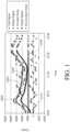
- FIG. 1is an exemplary graph illustrating the components of a signal measured by a glucose sensor (after sensor break-in was complete) in a non-diabetic volunteer host.
- the X-axisindicates time.
- the Y-axisindicates the signal amplitude (in counts) detected by the sensor.
- countsas used herein is a broad term, and is to be given its ordinary and customary meaning to a person of ordinary skill in the art (and is not to be limited to a special or customized meaning), and refers without limitation to a unit of measurement of a digital signal.
- a raw data stream measured in countsis directly related to a voltage (for example, converted by an A/D converter), which is directly related to current from a working electrode.
- the total signal collected by the sensoris represented by line 1000, which includes components related to glucose, constant noise, and non-constant noise, which are described in more detail elsewhere herein.
- the total signalis a raw data stream, which can include an averaged or integrated signal, for example, by using a charge-counting device.
- the non-constant noise component of the total signalis represented by line 1010.
- the non-constant noise component 1010 of the total signal 1000can be obtained by filtering the total signal 1000 to obtain a filtered signal 1020 using any of a variety of known filtering techniques, and then subtracting the filtered signal 1020 from the total signal 1000.
- the total signalcan be filtered using linear regression analysis of the n ( e.g., 10) most recent sampled sensor values.
- the total signalcan be filtered using non-linear regression.
- the total signalcan be filtered using a trimmed regression, which is a linear regression of a trimmed mean ( e . g ., after rejecting wide excursions of any point from the regression line).
- the sensorcalculates a trimmed mean (e.g., removes highest and lowest measurements from a data set) and then regresses the remaining measurements to estimate the glucose value.
- the total signalcan be filtered using a non-recursive filter, such as a finite impulse response (FIR) filter.
- FIRfinite impulse response
- An FIR filteris a digital signal filter, in which every sample of output is the weighted sum of past and current samples of input, using only some finite number of past samples.
- the total signalcan be filtered using a recursive filter, such as an infinite impulse response (IIR) filter.
- IIRinfinite impulse response
- An IIR filteris a type of digital signal filter, in which every sample of output is the weighted sum of past samples of input and output and current samples of input.
- the total signalcan be filtered using a maximum-average (max-average) filtering algorithm, which smoothes data based on the discovery that the substantial majority of signal artifacts observed after implantation of glucose sensors in humans, for example, is not distributed evenly above and below the actual blood glucose levels. It has been observed that many data sets are actually characterized by extended periods in which the noise appears to trend downwardly from maximum values with occasional high spikes. To overcome these downward trending signal artifacts, the max-average calculation tracks with the highest sensor values, and discards the bulk of the lower values.
- the max-average methodis designed to reduce the contamination of the data with unphysiologically high data from the high spikes.
- the max-average calculationsmoothes data at a sampling interval (e.g., every 30 seconds) for transmission to the receiver at a less frequent transmission interval ( e.g., every 5 minutes), to minimize the effects of low non-physiological data.
- the microprocessorfinds and stores a maximum sensor counts value in a first set of sampled data points ( e.g., 5 consecutive, accepted, thirty-second data points).
- a frame shift time windowfinds a maximum sensor counts value for each set of sampled data ( e . g ., each 5-point cycle length) and stores each maximum value.
- the microprocessorthen computes a rolling average ( e .
- the total signalcan be filtered using a "Cone of Possibility Replacement Method," which utilizes physiological information along with glucose signal values in order to define a "cone” of physiologically feasible glucose signal values within a human.
- physiological informationdepends upon the physiological parameters obtained from continuous studies in the literature as well as our own observations.
- a first physiological parameteruses a maximal sustained rate of change of glucose in humans (e.g., about 4 to 5 mg/dL/min) and a maximum sustained acceleration of that rate of change (e.g., about 0.1 to 0.2 mg/min/min).
- a second physiological parameteruses the knowledge that rate of change of glucose is lowest at the maxima and minima, which are the areas of greatest risk in patient treatment.
- a third physiological parameteruses the fact that the best solution for the shape of the curve at any point along the curve over a certain time period ( e.g., about 20-25 minutes) is a straight line. It is noted that the maximum rate of change can be narrowed in some instances.
- the maximum per minute rate changecan be lower when the subject is lying down or sleeping; on the other hand, the maximum per minute rate change can be higher when the subject is exercising, for example.
- the total signalcan be filtered using reference changes in electrode potential to estimate glucose sensor data during positive detection of signal artifacts from an electrochemical glucose sensor, the method hereinafter referred to as reference drift replacement.
- the electrochemical glucose sensorcomprises working, counter, and reference electrodes. This method exploits the function of the reference electrode as it drifts to compensate for counter electrode limitations during oxygen deficits, pH changes, and/or temperature changes.
- the constant noise signal component 1030can be obtained by calibrating the sensor signal using reference data, such as one or more blood glucose values obtained from a hand-held blood glucose meter, from which the baseline "b" of a regression can be obtained, representing the constant noise signal component 1030.
- reference datasuch as one or more blood glucose values obtained from a hand-held blood glucose meter, from which the baseline "b" of a regression can be obtained, representing the constant noise signal component 1030.
- noiseis also baseline.
- Other methods for calibrating the signalinclude those described in U.S. Patent Application Publication No. US-2005-0027463-A1 , U.S. Patent Application Publication No. US-2005-0187720-A1 , U.S. Patent Application Publication No. US-2005-0021666-A1 , U.S. Patent Application Publication No. US-2005-0027180-A1 , U.S.
- Patent Application Publication No. US-2005-0203360-A1U.S. Patent Application Publication No. US-2005-0043598-A1
- U.S. Patent Application Publication No. US-2007-0032706-A1U.S. Patent Application Publication No. US-2007-0016381-A1
- U.S. Patent Application Publication No. US-2008-0033254-A1U.S. Patent Application Publication No. US-2005-0143635-A1
- U.S. Patent Application Publication No. US-2007-0027385-A1U.S. Patent Application Publication No. US-2007-0213611-A1
- Patent Application Publication No. US-2008-0183061-A1U.S. Patent Application Publication No. US-2008-0200789-A1
- U.S. Patent Application Publication No. 2009-0192366-A1U.S. Patent Application Publication No. 2009-0192722-A1
- U.S. Patent Application Publication No. 2009-0156924-A1each of which is incorporated herein by reference in its entirety.
- the analyte signal component 1040was obtained by subtracting the constant noise signal component 1030 from the filtered signal 1020.
- Noiseis clinically important because it can induce error and can reduce sensor performance, such as by providing a signal that causes the analyte concentration to appear higher or lower than the actual analyte concentration.
- upward or high noisee.g., noise that causes the signal to increase
- downward or low noisee.g., noise that causes the signal to decrease
- noise reductionis desirable.
- Noisecan be caused by a variety of factors, ranging from mechanical factors to biological factors. For example, it is known that macro- or micro-motion, ischemia, pH changes, temperature changes, pressure, stress, or even unknown mechanical, electrical, and/or biochemical sources can cause noise, in some embodiments.
- Noise-causing specieswhich are known to cause non-constant noise, can be compounds, such as drugs that have been administered to the host ( e.g., externally derived), or intermittently produced products ( e.g., internally derived) of various host metabolic processes.
- noise-causing speciesinclude but are not limited to a variety of drugs (e.g., acetaminophen), H 2 O 2 from exterior sources (e.g., produced outside the sensor membrane), and reactive metabolic species (e.g., reactive oxygen and nitrogen species, some hormones, etc.).
- Some known noise-causing species for a glucose sensorinclude but are not limited to acetaminophen, ascorbic acid, bilirubin, cholesterol, creatinine, dopamine, ephedrine, ibuprofen, L-dopa, methyldopa, salicylate, tetracycline, tolazamide, tolbutamide, triglycerides, and uric acid.
- the membraneincludes a particle-containing domain located more distal to the electroactive surface than the enzyme and configured to electrochemically oxidize or electrochemically reduce noise-causing species, such as but not limited to noise causing species having an electrical potential that substantially overlaps with that of the measured compound ( e.g., H 2 O 2 ).
- noise-causing speciessuch as but not limited to noise causing species having an electrical potential that substantially overlaps with that of the measured compound ( e.g., H 2 O 2 ).
- a concentration increase of noise-causing electroactive speciescan interfere with sensor function and increase the level of noise observed during host sedentary periods.
- noise-causing electroactive speciessuch as electroactive metabolites from cellular metabolism and wound healing
- local lymph poolingwhich can occur when a part of the body is compressed or when the body is inactive, can cause, in part, this local build up of interferents ( e.g., electroactive metabolites).
- a local accumulation of wound healing metabolic productse.g., at the site of sensor insertion
- Noise-causing electroactive speciescan include, but are not limited to, compounds with electroactive acidic, amine or sulfhydryl groups, urea, lactic acid, phosphates, citrates, peroxides, amino acids (e.g., L-arginine), amino acid precursors or break-down products, nitric oxide (NO), NO-donors, NO-precursors or other electroactive species or metabolites produced during cell metabolism and/or wound healing, for example.
- amino acidse.g., L-arginine
- NOnitric oxide
- NO-donorsNO-precursors or other electroactive species or metabolites produced during cell metabolism and/or wound healing
- Noisecan be recognized and/or analyzed in a variety of ways. For example, in some circumstances, non-constant noise changes faster than the analyte signal and/or does not follow an expected analyte signal pattern; and lasts for a period of about 10 hours or more, 8 hours, 6 hours, 4 hours, 2 hours, 60 minutes, 30 minutes, or 10 minutes or less.
- the sensor data streamcan be monitored, signal artifacts detected, and data processing performed based at least in part on whether or not a signal artifact has been detected, such as described in U.S. Patent Application Publication No. US-2005-0043598-A1 , which is incorporated herein by reference in its entirety. Additional discussion of noise recognition and analysis can also be found in U.S. Patent Application Publication No. US-2007-0032706-A1 , which is incorporated herein by reference in its entirety.
- a signal component's percentage of the total signalcan be determined using a variety of methods of quantifying an amplitude of signal components and total signal, from each components percent contribution can be calculated.
- the signal component(s)can be quantified by comparing the peak-to-peak amplitudes of each signal component for a time period, whereby the peak-to-peak amplitudes of each component can be compared to the peak-to-peak amplitude of the total signal to determine it's percentage of the total signal.
- the signal component(s)can be quantified by determining the Root Mean Square (RMS) of the signal component for a time period.
- RMSRoot Mean Square
- a signale.g., analyte component, non-constant noise component, constant noise component, and/or total signal
- a predetermined time periode.g., about 1 day, about 2 days, about 3 days, etc.
- non-constant noisecan be a significant component of the total signal, such as 30 %, 40 %, 50 %, 60 % or more of the total signal. Additionally, non-constant noise can occur for durations of minutes or hours, in some circumstances. In some circumstances, non-constant noise can be equivalent to an analyte signal associated with a glucose concentration of about 400 mg/dL or more. Noise can induce error in the sensor reading, which can reduce sensor accuracy and clinically useful data. However, a high level of sensor accuracy is critical for successful patient care and desirable clinical outcomes.
- the particle-containing domainsuch as an electrode and/or membrane domain
- the particle-containing domainis formed of conductive particles dispersed in a non-conductive polymer or polymer blend, such that the negative effects of noise are substantially reduced and clinically useful data are provided to the user.
- the preferred embodimentsprovide a continuous analyte sensor that measures a concentration of the analyte of interest or a substance indicative of the concentration or presence of the analyte.
- the analyte sensoris an invasive, minimally invasive, or non-invasive device, for example a subcutaneous, transdermal, intravascular, or extracorporeal device.
- the analyte sensormay analyze a plurality of intermittent biological samples.
- the analyte sensormay use any method for analyte-measurement, including enzymatic, chemical, physical, electrochemical, spectrophotometric, polarimetric, calorimetric, radiometric, and the like.
- electrochemical analyte sensorsprovide at least one working electrode and at least one reference electrode, which are configured to measure a signal associated with a concentration of the analyte in the host, such as described in more detail below.
- the output signalis typically a raw data stream that is used to provide a useful value of the measured analyte concentration in a host to the patient or doctor, for example.
- continuous analyte sensorsdefine a relationship between sensor-generated measurements (for example, current in pA, nA, or digital counts after A/D conversion) and a reference measurement (for example, glucose concentration mg/dL or mmol/L) that are meaningful to a user (for example, patient or doctor).
- a reference measurementfor example, glucose concentration mg/dL or mmol/L
- the sensing mechanismgenerally depends on phenomena that are linear with glucose concentration, for example: (1) diffusion of glucose through a membrane (e.g., biointerface membrane) situated between implantation site and/or the electrode surface, (2) an enzymatic reaction within the membrane, and (3) diffusion of the H 2 O 2 to the sensor.
- ymx + b
- ythe sensor signal ( e . g ., counts)
- xthe estimated glucose concentration (e.g., mg/dL)
- mthe sensor sensitivity to glucose ( e.g., counts/mg/dL)
- bthe baseline signal ( e.g., counts).
- Matched data pairscan be created by matching reference data (for example, one or more reference glucose data points from a blood glucose meter, and the like) with substantially time corresponding sensor data (for example, one or more glucose sensor data points) to provide one or more matched data pairs, such as described in co-pending U.S. Patent Application Publication No. US-2005-0027463-A1 , which is incorporated herein by reference in its entirety.
- reference datafor example, one or more reference glucose data points from a blood glucose meter, and the like
- sensor datafor example, one or more glucose sensor data points
- the sensing layerutilizes immobilized mediators (e.g., redox compounds) to electrically connect the enzyme to the working electrode, rather than using a diffusional mediator.
- immobilized mediatorse.g., redox compounds
- the systemhas two oxygen sensors situated in an oxygen-permeable housing, one sensor being unaltered and the other contacting glucose oxidase allowing for differential measurement of oxygen content in bodily fluids or tissues indicative of glucose levels.
- two oxygen sensorssituated in an oxygen-permeable housing, one sensor being unaltered and the other contacting glucose oxidase allowing for differential measurement of oxygen content in bodily fluids or tissues indicative of glucose levels.
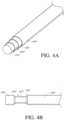
- an analyte sensorincludes a sensing mechanism 34 with a small structure (e.g., small-structured, micro- or small diameter sensor), for example, a needle-type sensor, in at least a portion thereof (see FIG. 2 ).
- a small structuree.g., small-structured, micro- or small diameter sensor
- the term "small-structured”preferably refers to an architecture with at least one dimension less than about 1 mm.
- the small structured sensing mechanismcan be wire-based, substrate based, or any other architecture.
- the term "small-structured”can also refer to slightly larger structures, such as those having their smallest dimension being greater than about 1 mm, however, the architecture (e.g., mass or size) is designed to minimize the foreign body response (FBR) due to size and/or mass.
- FBRforeign body response
- a biointerface membranee.g., membrane or sensing membrane
- the sensoris configured to be wholly implanted in a host, such as in the host abdomen; such is described in U.S. Patent Application Publication No. US-2006-0020187-A1 .
- the sensoris configured to be implanted in a host vessel or extracorporeally, such as is described in U.S. Patent Application Publication No. US-2007-0027385-A1 , U.S. Patent Application Publication No. US-2008-0108942-A1 , and U.S. Patent Application Publication No. US-2007-0197890-A1 , and U.S. Patent Application Publication No. US-2008-0119703-A1 , each of which is incorporated herein by reference in its entirety.
- the senoris an enzyme-based electrochemical sensor, wherein the working electrode 38 measures the hydrogen peroxide (H 2 O 2 ) produced by the enzyme catalyzed reaction of glucose being detected and creates a measurable electronic current (for example, detection of glucose utilizing glucose oxidase produces hydrogen peroxide as a byproduct, H 2 O 2 reacts with the surface of the working electrode producing two protons (2H + ), two electrons (2e - ) and one molecule of oxygen (O 2 ) which produces the electronic current being detected), such as described in more detail herein.
- one or more potentiostat(s)is employed to monitor the electrochemical reaction at the electroactive surface of the working electrode(s).
- the potentiostatapplies a potential to the working electrode and its associated reference electrode to determine the current produced at the working electrode.
- the current that is produced at the working electrode (and flows through the circuitry to the counter electrode)is substantially proportional to the amount of H 2 O 2 that diffuses to the working electrode.
- the output signalis typically a raw data stream that is used to provide a useful value of the measured analyte concentration in a host to the host or doctor, for example.
- the sensing mechanismincludes electrodes deposited on a planar substrate, wherein the thickness of the implantable portion is less than about 1 mm. See, for example, U.S. Patent No. 6,175,752 and U.S. Patent No. 5,779,665 .
- Some alternative analyte sensorsthat can benefit from the systems and methods of some embodiments include U.S. Patent No. 5,711,861 , U.S. Patent No. 6,642,015 , U.S. Patent No. 6,654,625 , U.S. Patent 6,565,509 , U.S. Patent No. 6,514,718 , U.S. Patent No. 6,465,066 , U.S. Patent No. 6,214,185 , U.S. Patent No. 5,310,469 , and U.S. Patent No. 5,683,562 , U.S. Patent No. 6,579,690 , U.S. Patent No. 6,484,046 , U.S. Patent No.
- FIG. 2is a perspective view of the in vivo portion of an exemplary embodiment of a continuous analyte sensor 34, also referred to as a transcutaneous analyte sensor, or needle-type sensor, particularly illustrating the sensing mechanism.
- the sensing mechanismcomprises a small structure as defined herein and is adapted for insertion under the host's skin, and the remaining body of the sensor ( e.g., electronics, etc.) can reside ex vivo.
- the analyte sensoris configured for exposure to the host's circulatory system, extracorporeal and/or wholly implantable.
- the analyte sensor 34includes two electrodes, i.e., a working electrode 38 and at least one additional electrode 30, which may function as a counter and/or reference electrode, hereinafter referred to as the reference electrode 30.
- each electrodeis formed from a fine wire with a diameter of from about 0.001 or less to about 0.01 inches or more, for example, and is formed from, e.g., a plated insulator, a plated wire, or bulk electrically conductive material.
- a variety of known transcutaneous sensor configurationscan be employed with the transcutaneous analyte sensor system of some embodiments, such as are described in U.S. Patent No. 6,695,860 to Ward et a / ., U.S. Patent No. 6,565,509 to Say et a / ., U.S. Patent No. 6,248,067 to Causey III et a / ., and U.S. Patent No. 6,514,718 to Heller et al.
- the working electrodecomprises a wire formed from a conductive material, such as platinum, platinum-iridium, palladium, graphite, gold, carbon, conductive polymer, alloys, and the like.
- a conductive materialsuch as platinum, platinum-iridium, palladium, graphite, gold, carbon, conductive polymer, alloys, and the like.
- the electrodescan by formed by a variety of manufacturing techniques (bulk metal processing, deposition of metal onto a substrate, and the like), it can be advantageous to form the electrodes from plated wire (e.g., platinum on steel wire) or bulk metal ( e.g., platinum wire).
- electrodes formed from bulk metal wireprovide superior performance (e.g., in contrast to deposited electrodes), including increased stability of assay, simplified manufacturability, resistance to contamination ( e.g., which can be introduced in deposition processes), and improved surface reaction ( e.g., due to purity of material) without peeling or delamination.
- electrodecan be formed of a plurality of conductive particles distributed throughout a non-conductive component, such as but not limited to a polymer or a polymer blend.
- Such "particulate electrodes”have the advantage of reduced material costs, moldability/conformability, and material properties, such as strength and fatigue resistance due to the non-conductive ( e.g., polymer) component.
- the working electrode 38is configured to measure the concentration of an analyte, such as but not limited to glucose, uric acid, cholesterol, lactate and the like.
- an analytesuch as but not limited to glucose, uric acid, cholesterol, lactate and the like.
- the working electrodemeasures the hydrogen peroxide produced by an enzyme catalyzed reaction of the analyte being detected and creates a measurable electronic current.
- glucose oxidaseGOX
- H 2 O 2reacts with the surface of the working electrode producing two protons (2H + ), two electrons (2e - ) and one molecule of oxygen (O 2 ), which produces the electronic current being detected.
- the working electrode 38is covered with an insulating material, for example, a non-conductive polymer. Dip-coating, spray-coating, vapor-deposition, or other coating or deposition techniques can be used to deposit the insulating material on the working electrode.
- the insulating materialcomprises parylene, which can be an advantageous polymer coating for its strength, lubricity, and electrical insulation properties. Generally, parylene is produced by vapor deposition and polymerization of para-xylylene (or its substituted derivatives).
- any suitable insulating materialcan be used, for example, fluorinated polymers, polyethyleneterephthalate, polyurethane, polyimide, other nonconducting polymers, and the like. Glass or ceramic materials can also be employed.
- the working electrodemay not require a coating of insulator.
- the reference electrode 30,which may function as a reference electrode alone, or as a dual reference and counter electrode, is formed from silver, silver/silver chloride and the like.
- the electrodesare juxtapositioned and/or twisted ( e.g., coaxial) with or around each other; however other configurations are also possible.
- the reference electrode 30is helically wound around the working electrode 38 as illustrated in FIG. 2 .
- the assembly of wiresmay then be optionally coated together with an insulating material, similar to that described above, in order to provide an insulating attachment (e.g., securing together of the working and reference electrodes). Additional description of sensor electrodes can be found in U.S. Patent Application Publication No. US-2006-0015024-A1 and U.S. Patent Application Publication No. US-2006-0020187-A1 , each of which is incorporated herein by reference in its entirety.
- a radial windowis formed through the insulating material to expose a circumferential electroactive surface of the working electrode, using known methods. Additionally, sections of electroactive surface of the reference electrode are exposed. Alternatively, a tangential exposed electroactive window can be formed, for example, by stripping only one side of the coated assembly structure. In other alternative embodiments, the window can be provided at the tip of the coated assembly structure such that the electroactive surfaces are exposed at the tip of the sensor. Other methods and configurations for exposing electroactive surfaces can also be employed.
- additional electrodescan be included within the assembly, for example, a three-electrode system (working, reference, and counter electrodes) and/or an additional working electrode (e.g., an electrode which can be used to generate oxygen, which is configured as a baseline subtracting electrode, or which is configured for measuring additional analytes).
- a three-electrode systemworking, reference, and counter electrodes
- an additional working electrodee.g., an electrode which can be used to generate oxygen, which is configured as a baseline subtracting electrode, or which is configured for measuring additional analytes.
- the senorincludes a first working electrode, which is configured to detect a signal comprising analyte-related signal and non-analyte related signal (e.g., noise-causing species) components, and a second working electrode, which is configured to detect only the non-analyte related signal component, wherein the signal detected via the second working electrode can be used to determine the component of the total signal related to only the analyte.
- the sensoris configured and arranged to detect two or more analytes, and can include two or more working electrodes (e.g., a glucose-detecting working electrode and a potassium-detecting working electrode), a reference electrode and/or a counter electrode, for example, U.S. Patent No.
- the sensing regionmay include reference and/or other electrodes associated with the glucose-measuring working electrode and/or separate reference and/or counter electrodes associated with optional auxiliary working electrode(s).
- the sensing regionmay include a glucose-measuring working electrode, an auxiliary working electrode, two counter electrodes (one for each working electrode), and one shared reference electrode.
- the sensing regionmay include a glucose-measuring working electrode, an auxiliary working electrode, two reference electrodes, and one shared counter electrode.
- a variety of electrode materials and configurationscan be used with the implantable analyte sensor of the preferred embodiments.
- a membrane 32is disposed over the sensor's electrodes and provides one or more of the following functions: 1) protection of the exposed electrode surface from the biological environment (e.g., cell impermeable domain); 2) diffusion resistance (limitation) of the analyte ( e.g., resistance domain); 3) a catalyst for enabling an enzymatic reaction (e.g., enzyme domain); 4) limitation or blocking of interfering species (e.g., particle-containing domain and optional interference domain); and/or 5) hydrophilicity at the electrochemically reactive surfaces of the sensor interface (e.g. , electrolyte domain).
- a sensing membrane modified for other sensorsfor example, by including fewer or additional domains is within the scope of some embodiments.
- the membranecan be located over the sensor body by mechanical or chemical methods such as described in U.S. Patent Application Publication Nos. 2006/0015020 and 2005/0245799 , each of which is incorporated herein by reference in their entirety. Additional description of the membrane 32 can be found in U.S. Patent Application Publication No. US-2005-0245799-A1 and U.S. Patent Application Publication No. US-2005-0242479-A1 (which describes biointerface and sensing membrane configurations and materials that may be applied to some embodiments), each of which is incorporated herein by reference in its entirety.
- FIG. 3is a cross-sectional view through the sensor of FIG. 2 on line 3-3, illustrating the membrane 32 in one embodiment.
- the membraneincludes an electrode domain 43, an interference domain 44, and enzyme domain 46, a diffusion resistance domain 48, and a particle-containing domain 50 wrapped around the platinum wire working electrode 38.
- this membranecan include additional domains, as described herein.
- the transcutaneous wire sensoris configured for short-term implantation ( e.g., from about 1 to 30 days).
- the sensoris configured for intravascular or extracorporeal implantation (see, e.g., U.S. Patent Application Publication No. US-2005-0143635-A1 , U.S. Patent Application Publication No.
- the senoris configured for long-term implantation, such as a wholly implantable sensor, for example.
- the membrane 32( e .
- sensing membraneof some embodiments includes an enzyme domain 46, a resistance domain 48, and a particle-containing domain 50, and may include additional domains, such as an electrode domain 43, and interference domain 44, a cell impermeable domain (also referred to as a bioprotective layer), and/or an oxygen domain (not shown).
- additional domainssuch as an electrode domain 43, and interference domain 44, a cell impermeable domain (also referred to as a bioprotective layer), and/or an oxygen domain (not shown).
- the membrane 32is disposed over the electroactive surfaces of the electrode system and provides one or more of the following functions: 1) protection of the exposed electrode surface from the biological environment (cell impermeable domain); 2) diffusion resistance (limitation) of the analyte (resistance domain); 3) a catalyst for enabling an enzymatic reaction (enzyme domain); 4) limitation or blocking of interfering species (particle-containing domain and optional interference domain); and/or 5) hydrophilicity at the electrochemically reactive surfaces of the sensor interface (electrolyte domain).
- a sensing membrane modified for other sensorsfor example, by including fewer or additional domains is within the scope of some embodiments.
- the membranecan be located over the sensor body by mechanical or chemical methods such as described in U.S. Patent Application Publication No. US-2006-0015020-A1 and U.S. Patent Application Publication No. US-2005-0245799-A1 , which are incorporated herein by reference in their entirety. Additional description of the membrane 32 can be found in U.S. Patent Application Publication No. US-2005-0245799-A1 and U.S. Patent Application Publication No. US-2005-0242479-A1 (which describes biointerface and sensing membrane configurations and materials that may be applied to some embodiments) each of which is incorporated herein by reference in its entirety.
- the sensing membranecan be deposited on the electroactive surfaces of the electrode material using known thin or thick film techniques (for example, spraying, electro-depositing, dipping, casting separately from the sensor and then wrapped around it, printing, and the like). It is noted that the sensing membrane that surrounds the working electrode does not have to be the same structure as the sensing membrane that surrounds a reference electrode, etc. For example, the enzyme domain deposited over the working electrode does not necessarily need to be deposited over the reference and/or counter electrodes.
- FIG. 4Aillustrates another embodiment of an electrode.
- the electrodecomprises a conductive core 410, a first layer 420 that at least partially surrounds the core 410, a second layer 430 that at least partially surrounds the first layer 420, and a third layer 440 that at least partially surrounds the second layer 430.
- These layerswhich collectively form an elongated body, can be deposited onto the conductive core by any of a variety of techniques, such as, for example, by employing dip coating, plating, extrusion, or spray coating processes.
- the first layer 420can comprise a conductive material, such as, for example, platinum, platinum-iridium, gold, palladium, iridium, graphite, carbon, a conductive polymer, an alloy, and/or the like, configured to provide suitable electroactive surfaces for one or more working electrodes.
- the second layer 430can correspond to an insulator and comprise an insulating material, such as a non-conductive (e . g ., dielectric) polymer ( e . g ., polyurethane, polyimide, or parylene).
- the third layer 440can correspond to a reference electrode and comprise a conductive material, such as, a silver-containing material, including, but not limited to, a polymer-based conducting mixture.
- FIG. 4Billustrates one embodiment of the electrode of FIG. 4A , after it has undergone laser ablation treatment. As shown, a window region 422 is formed when the ablation removes the second and third layers 430, 440, to expose an electroactive surface of the first conductive layer 420, wherein the exposed electroactive surface of the first conductive layer 420 correspond to a working electrode.
- FIG. 5Aillustrates another embodiment of an electrode.
- the electrodein addition to an conductive core 510, a first layer 520, a second layer 530, and a third layer 540, the electrode further comprises a fourth layer 550 and a fifth layer 570.
- the first layer 520 and the second layer 530can be formed of a conductive material and an insulating material, respectively, similar to those described in the embodiment of FIG. 4A .
- the third layer 540can be configured to provide the sensor with a second working electrode, in addition to the first working electrode provided by the first layer 520.
- the fourth layer 550can comprise an insulating material and provide insulation between the third layer 540 and the fifth layer 560, which can correspond to a reference electrode and comprise the aforementioned silver-containing material. It is contemplated that other similar embodiments are possible.
- the electrodecan have 6, 7, 8, 9, 10, or more layers, each of which can be formed of conductive or non-conductive material.
- FIG. 5Billustrates one embodiment of the electrode of FIG. 5A , after it has undergone laser ablation treatment. Here, two window regions, a first window region 522 and a second window region 542, are formed, with each window region having a different depth and corresponding to a working electrode distinct from the other.
- the continuous analyte sensorincludes a particle-containing domain 50 that is capable of reducing noise derived from noise-causing species, such as non-constant noise and/or constant noise.
- the particle-containing domain 50is capable of scavenging certain compounds (e . g ., interfering species, non-reaction-related hydrogen peroxide, or other electroactive species with an oxidation potential that overlaps with that of hydrogen peroxide) that contribute to non-glucose related signal before they reach the working electrode.
- the particle-containing domainis located more distal to ( e . g ., radially outward) the sensor's electroactive surface than the enzyme ( e .
- FIG. 3shows the particle-containing domain 50 as being the most distal membrane domain. However, the particle-containing domain can be located adjacent to the enzyme domain, or between the enzyme domain and a more distal domain.
- the membrane of FIG. 3is depicted as being composed of several membrane layers or domains. However, in some embodiments, the membrane can be formed of a single layer that comprises structural and/or functional regions ( e . g ., the layer can be stratified, as in a gradient).
- the single layercan comprise three regions, a proximal region containing the enzyme, an intermediate region configured to restrict diffusion of excess analyte, and a distal region containing the conductive particles dispersed in the material of which the layer is formed and functioning as a particle-containing domain.
- the membranecan be formed of two layers, such as a proximal enzyme domain/layer and a distal domain/layer that contains structural and/or functional regions, such as a region that contains the conductive particles and functions as a particle-containing domain.
- interfering species, non-reaction-related hydrogen peroxide, and/or other electroactive species with an oxidation potential that overlaps with hydrogen peroxideare oxidized/reduced at a location other than the working (measuring) electrode.
- sensor baselineis reduced and stabilized, break-in time is reduced, and sensor accuracy is improved.
- noise-causing speciescan be reduced at a potential of from about ⁇ 0.1V to about ⁇ 1.2V or more/less; for example, acetaminophen is reduced at a potential of about +0.4 V.
- the particle-containing domainis configured to electrochemically oxidize or electrochemically reduce (e . g ., electrochemically oxidize/reduce) at least one noise-causing species having a potential within this range, such that the noise-causing species does not substantially interact with the electroactive surface, or contribute to the total signal, as described elsewhere herein.
- the particle-containing domainis configured and arranged to electrochemically oxidize or electrochemically reduce an amount of non-constant noise-causing species, such that the non-constant noise component of the signal is less than about 20% of the total signal. In more preferred embodiments, the non-constant noise component of the signal is less than about 10% of the total signal. In still more preferred embodiments, the non-constant noise component of the signal is less than about 5% of the total signal.
- no potentialis applied to the particle-containing domain (e.g., a "non-powered" particle-containing domain).
- Non-powered particle-containing domainscan be less complicated and less expensive to manufacture, as compared to other types of particle-containing domains described herein.
- a potentialis applied to the particle-containing domain (a "powered" particle-containing domain). Applying power to the particle-containing domain (e . g ., the powered particle-containing domain) can increase the range of noise-causing species that can be electrochemically oxidized/reduced, such as to species having a redox potential outside of the +0.1V to about ⁇ 1.2V range of the non-powered particle-containing domain.
- a particle-containing domainis configured to be alternately powered and non-powered for periods of time.
- a non-powered particle-containing domainis configured to generate a potential (e . g ., self-powered particle-containing domain).
- Self-powered particle-containing domainscan be less expensive/complicated to manufacture than the powered particle-containing domains but can oxidize/reduce a wider range of interfering compounds than a non-powered particle-containing domain.
- a sensorincludes two or more particle-containing domains, such as, powered and non-powered domains, powered and self-powered domains, non-powered and self-powered domains, or two different types of non-powered domains, for example.
- the particle-containing domain 50may comprise a non-conductive component with a conductive component dispersed therein, for example, wherein the conductive component comprises a plurality of conductive particles having a sufficient concentration such that current can be transferred between particles, such that the membrane domain is conductive.
- the non-conductive component of the particle-containing domaincomprises a polymer.
- the polymeris analyte-permeable, for example, wherein an analyte, such as glucose, can diffuse through the polymer.
- the polymercomprises a hydrophilic polymer.
- the polymercomprises at least one of polyurethane or silicone. A variety of hydrophilic polymers, which find use in the preferred embodiments, are described elsewhere herein.
- the particle-containing domainmay include a conductive component dispersed throughout a non-conductive component.
- the conductive componentcomprises a plurality of conductive particles.
- the conductive particlescan have a variety of shapes such as but not limited to spherical shapes, irregular, three-dimensional shapes, fibers, micro-laminates of conductive materials and the like, including blends, amalgams, laminates, and the like.
- the conductive particlesmay have any appropriate size.
- the particlesmay be on average from about 0.01 microns to about 2 microns in diameter, preferably from about 0.03 microns to about 1 micron in diameter, and more preferably from about 0.05 microns to about 0.5 microns in diameter.
- the particlesmay have an average weight of from about 1 ⁇ 10 -17 grams to about 1 ⁇ 10 -10 grams, preferably from about 1 ⁇ 10 -15 grams to about 1 ⁇ 10 -11 grams, and more preferably from about 1 ⁇ 10 -13 grams to about 1 ⁇ 10 -12 grams.
- the conductive particlescan be of any suitable material.
- the conductive componentis a metal, such as but not limited to platinum, iridium, platinum-iridium, palladium, ruthenium, rhodium, osmium, carbon, graphite, platinum-coated carbon, platinum-coated graphite, gold, and the like.
- the conductive componentis a conductive polymer, such as but not limited to polyacetylene, polypyrrole, polythiophene, polyaniline, polyfluorene, poly(3-alkylthiophene), polytetrathiafulvalene, polynaphthalenes, poly(p-phenylene sulfide), and poly(para-phenylene vinylene).
- the conductive componentincludes a blend of metals and/or conductive polymers.
- the conductive particlescan be substantially homogeneous or heterogeneous in shape, size, surface area, or composition.
- the conductive particleshave a concentration that is sufficient for the particle-containing domain to function as conductive film.
- the concentration of the conductive particles within the particle-containing domain, in volume percentageis from about 0.1% to about 99.9% of the total volume of the particle-containing domain, preferably from about 0.5% to about 5%, more preferably from about 15% to about 45%, most preferably from about 50% to about 80%.
- the particle-containing domaincontains from about 1 wt. % or less to about 90 wt. % or more conductive component dispersed in the non-conductive component. In some embodiments, the particle-containing domain contains from about 10 wt. % to about 60 wt.
- the particle-containing domaincontains from about 20 wt. % to about 40 wt. % or more conductive particles dispersed in the non-conductive component. Increasing the number and/or volume of conductive particles tends to increase the surface area of the particles that are present on the surface of the particle-containing domain.
- the effective surface area of the particle-containing domainis more than about 2 times greater than an effective surface of a corresponding domain without conductive particles, preferably more than about 3 times greater, more preferably more than about 5 times greater, more preferably more than about 7 times greater, more preferably more than about 10 times greater, more preferably more than about 20 times greater, more preferably more than about 25 times greater, and most preferably more than about 25 times greater.
- an increase in the effective surface area of the particle-containing domaintends to also increase the effective surface area of the interface between the particle-containing domain and the biological sample ( e .
- analytes and oxygencan diffuse through the membrane, thereby providing amplification of the analyte signal, as compared to a signal of a corresponding domain without particles.
- electrochemical reactions involving the analyteoccurs substantially at the top surface of the domain or of the electroactive surface of the electrode, and the material ( e . g ., AgCl) used to form the electrode may be consumed during the lifetime of the sensor.
- the lifetime for the sensormay be lengthened.
- particlesare incorporated into the particle-containing domain to create an uneven and/or irregular surface, such that the effective surface area of the particle-containing domain increases by more than about 20 times, compared to a corresponding domain without the particles and with a substantially evened surface, preferably by more than about 15 times, more preferably by more than about 10 times, more preferably by more than about 3 times, more preferably by more than about 2 times, more preferably by more than about 85 percent, more preferably by more than about 50 percent, and more preferably by more than about 20 percent.
- the surface area of the particle-containing domaincan also be increased by increasing the surface area of the particles, some of which are present on the surface of the particle-containing domain.
- the average surface area of the particlesis greater than about 20 m 2 /g, preferably greater than about 50 m 2 /g, more preferably greater than about 100 m 2 /g, more preferably greater than about 200 m 2 /g and most preferably greater than about 400 m 2 /g, as determined by the BET (Brunauer, Emmett, Teller) method for determining surface area by physical adsorption of gas molecules.
- BETBrunauer, Emmett, Teller
- the particle-containing domainis configured and arranged to electrochemically oxidize or electrochemically reduce an amount of non-constant noise-causing species, such that the non-constant noise component of the signal is less than about 20% of the total signal. In some embodiments, the non-constant noise component of the signal is less than about 18%, 15%, 10%, 8%, 5%, 3%, or 1% of the total signal for a time period of about 1, 3, 5, 7 or more days.
- the conductive componenthas a sufficiently low reduction/oxidation potential so that a noise-causing (e . g ., background-causing) species can be oxidized/reduced, such that the negative effects of noise are substantially reduced, and clinically useful data are provided to the user.
- a noise-causing speciese . g ., background-causing
- the non-conductive componentin which the conductive component (e . g ., conductive particles) is dispersed, is a polymer.
- the polymeris analyte-permeable.
- Analyte-permeable polymersthat may be used include but are not limited to, hydrophilic and hydrophobic polymer blends that are sufficiently hydrophilic such that the analyte ( e . g ., glucose) can pass therethrough.
- These analyte-permeable polymersinclude but not limited to polyurethanes, polyurethane ureas having about 5% to about 45% hydrophile ( e .
- siliconese . g ., PEO, PVD, or Pluronics
- siliconessilicone blends
- silicone polymer/hydrophobic-hydrophilic polymer blendincluding but not limited to components such as polyvinylpyrrolidone (PVP), polyhydroxyethyl methacrylate, polyvinylalcohol, polyacrylic acid, polyethers such as polyethylene glycol or polypropylene oxide, and copolymers thereof, including, for example, di-block, tri-block, alternating, random, comb, star, dendritic, and graft copolymers). Additional description of hydrophilic and hydrophobic material blends can be found U.S. Patent Application Publication No.
- the particle-containing domaincomprises a blend of a silicone polymer with a hydrophilic polymer.
- hydrophilic polymerit is meant that the polymer has an affinity for water, due to the presence of one or more hydrophilic substituents, and generally is primarily soluble in water or has a tendency to absorb water.
- the hydrophilic component of a hydrophilic polymerpromotes the movement of water and/or compounds in the water ( e . g ., by diffusion or other means) through a membrane formed of the hydrophilic polymer, such as by lowering the thermodynamic barrier to movement of compounds in the water into the membrane.
- Some polymersinclude both hydrophilic and hydrophobic substituents.
- the hydrophilic and hydrophobic substituents of a polymercan affect the polymer's behavior in certain circumstances, as seen, for example, in silicone/hydrophilic-hydrophobic blend materials and micellar jackets, which are discussed elsewhere herein.
- PEO-PPO-PEOthe polymer's major component (PEO) is hydrophilic and can provide an overall hydrophilic character to the molecule ( e . g ., the molecule generally behaves in a hydrophilic manner).
- the hydrophobic component (PPO) of the polymermakes it possible for the polymer to have some hydrophobic character ( e .
- micellar jacketsfor portions of the molecule to behave in the manner of a hydrophobic molecule, in some situations.
- the polymerself-organizes, relative to the silicone ( e . g ., silicone globule(s)) such that the hydrophobic PPO is adjacent to the silicone (which is hydrophobic) and the two PEO groups project away from the silicone ( e.g., due to thermodynamic forces).
- variations of the micellar jacket structure described abovee.g., opposite orientations
- the PPO groupsself-orient toward the silicone and the PEO center is oriented away from the silicone.
- the non-conductive componentincludes at least one polymer containing a surface-active group (see U.S. Patent Application No. 12/413,231, filed March 27, 2009 and entitled “Polymer Membranes for Continuous In Vivo Analyte Sensors" and U.S. Patent Application No. 12/413,166, filed March 27, 2009 and entitled “Polymer Membranes for Continuous In Vivo Analyte Sensors,” each of which is incorporated by reference herein in its entirety).
- the surface-active group-containing polymeris a surface-active end group-containing polymer.
- the surface-active end group-containing polymeris a polymer having covalently bonded surface-active end groups.
- surface-active group-containing polymerscan be formed by: modification of fully-reacted base polymers via the grafting of side chain structures; surface treatments or coatings applied after membrane fabrication ( e.g., via surface-modifying additives); blending of a surface-modifying additive to a base polymer before membrane fabrication; immobilization of by physical entrainment during synthesis; and/or the like.
- Base polymers useful for the preferred embodimentsinclude any linear and/or branched polymer on the backbone structure of the polymer.
- Suitable base polymersinclude epoxies, polyolefins, polysiloxanes, polyethers, acrylics, polyesters, carbonates, and polyurethanes, wherein polyurethanes include polyurethane copolymers such as polyether-urethane-urea, polycarbonate-urethane, polyether-urethane, silicone-polyether-urethane, silicone-polycarbonate-urethane, polyester-urethane, and/or the like.
- Advantageous base polymers of the preferred embodimentsare selected for their bulk properties, for example, tensile strength, flex life, modulus, and/or the like, for example, polyurethanes are known to be relatively strong and provide numerous reactive pathways, which properties are advantageous as bulk properties for a membrane domain of the preferred embodiments.
- Preferred linear base polymersinclude biocompatible segmented block polyurethane copolymers comprising hard and soft segments.
- the hard segment of the copolymerhas a molecular weight of from about 160 to about 10,000, and more preferably from about 200 to about 2,000; while the preferred molecular weight of the soft segment is from about 200 to about 1,000,000, and more preferably from about 400 to 9,000.
- Preferred polyisocyanates for the preparation of the hard segment of the copolymerare aromatic or aliphatic diisocyanates.
- the soft segment used in the preparation of the polyurethaneis preferably a polyfunctional aliphatic polyol, a polyfunctional aliphatic or aromatic amine, and/or the like useful for creating permeability of the analyte (e.g., glucose) therethrough, for example, polyvinyl acetate (PVA), polyethylene glycol) (PEG), polyacrylamide, acetates.
- PEOpolyethylene oxide
- PEApolyethylacrylate
- PVPpolyvinylpyrrolidone
- variations thereofe.g., PVP vinyl acetate
- surface-active groupand "surface-active end group” as used herein are broad terms and are used in their ordinary sense, including, without limitation, surface-active oligomers or other surface-active moieties having surface-active properties, such as alkyl groups, which preferentially migrate towards a surface of a membrane formed there from. Surface active groups preferentially migrate towards air (e.g., driven by thermodynamic properties during membrane formation). In some embodiments, the surface-active groups are covalently bonded to the base polymer during synthesis. In some preferred embodiments, surface-active groups include silicone, sulfonate, fluorine, polyethylene oxide, hydrocarbon groups, and the like.
- the surface activity (e.g., chemistry, properties) of a membrane domain including a surface-active group-containing polymerreflects the surface activity of the surface-active groups rather than that of the base polymer.
- surface-active groupscontrol the chemistry at the surface (e.g., the biological contacting surface) of the membrane without compromising the bulk properties of the base polymer.
- the surface-active groups of the preferred embodimentsare selected for desirable surface properties, for example, non-constant noise-blocking ability, break-in time (reduced), ability to repel charged species, cationic or anionic blocking, and/or the like.
- the surface-active groupsare located on one or more ends of the polymer backbone, and referred to as surface-active end groups, wherein the surface-active end groups are believed to more readily migrate the surface of the biointerface domain/layer formed from the surface-active group-containing polymer in some circumstances. Additional description of surface-modified polymers and/or membranes can be found in U.S. Patent Application No. 12/413,231, filed March 27, 2009 and entitled “Polymer Membranes for Continuous In Vivo Analyte Sensors" and U.S. Patent Application No. 12/413,166, filed March 27, 2009 and entitled “Polymer Membranes for Continuous In Vivo Analyte Sensors,” each of which is incorporated by reference herein in its entirety.
- one or more domains of the membraneare formed from materials such as silicone, polytetrafluoroethylene, polyethylene-co-tetrafluoroethylene, polyolefin, polyester, polycarbonate, biostable polytetrafluoroethylene, homopolymers, copolymers, terpolymers of polyurethanes, polypropylene (PP), polyvinylchloride (PVC), polyvinylidene fluoride (PVDF), polybutylene terephthalate (PBT), polymethylmethacrylate (PMMA), polyether ether ketone (PEEK), polyurethanes, cellulosic polymers, polyethylene oxide), polypropylene oxide) and copolymers and blends thereof, polysulfones and block copolymers thereof including, for example, di-block, tri-block, alternating, random and graft copolymers.
- materialssuch as silicone, polytetrafluoroethylene, polyethylene-co-tetrafluoroethylene, poly
- the particle-containing domain 50includes a polyurethane (or polyurethane urea) membrane with both hydrophilic and hydrophobic regions to control the diffusion of glucose and oxygen to an analyte sensor, the membrane being fabricated easily and reproducibly from commercially available materials.
- Polyurethaneis a polymer produced by the condensation reaction of a diisocyanate and a difunctional hydroxyl-containing material.
- a polyurethaneureais a polymer produced by the condensation reaction of a diisocyanate and a difunctional amine-containing material.
- Preferred diisocyanatesinclude aliphatic diisocyanates containing from about 4 to about 8 methylene units.
- Diisocyanates containing cycloaliphatic moietiescan also be useful in the preparation of the polymer.
- the material that forms the particle-containing domaincan be any of those known in the art as appropriate for use in membranes in sensor device and as having sufficient permeability to allow relevant compounds to pass through it, for example, to allow an oxygen molecule to pass through the membrane from the sample under examination in order to reach the active enzyme or electrochemical electrodes.
- the particle-containing domaincan be configured from non-polyurethane type materials including but not limited to vinyl polymers, polyethers, polyesters, polyamides, inorganic polymers such as polysiloxanes and polycarbosiloxanes, natural polymers such as cellulosic and protein based materials, and mixtures of combinations thereof. Additional description of polyurethane membranes can be found in PCT International Publication No. WO 1992/013271 .
- the particle-containing domainis deposited on to the enzyme domain, such as, but not limited to, one that is part of a membrane system comprising as one or more planar and/or concentric layers.
- the depositionmay yield a domain thickness from about 0.05 microns or less to about 20 microns or more, more preferably from about 0.05, 0.1, 0.15, 0.2, 0.25, 0.3, 0.35, 0.4, 0.45, 0.5, 1, 1.5, 2, 2.5, 3, or 3.5 microns to about 4, 5, 6, 7, 8, 9, 10, 11, 12, 13, 14, 15, 16, 17, 18, 19, or 19.5 microns, and more preferably still from about 2, 2.5, or 3 microns to about 3.5, 4, 4.5, or 5 microns.
- the particle-containing domainmay be deposited by any of variety of techniques, such as, vapor deposition, spray coating, spin coating, or dip coating, for example. In one preferred embodiment, dipping is the preferred deposition technique.
- some of the particle-containing domains described hereinmay have a conductive particles concentration that is sufficient for the particle-containing domains to function as conductive films.
- some of these particle-containing domainsare capable of allowing for diffusion of certain analytes (e.g., glucose) and gases (e.g., oxygen) therethrough.
- the particle-containing domainhas a glucose diffusion coefficient greater than about 1 ⁇ 10 -15 m 2 /s in vivo, preferably greater than about 1 ⁇ 10 -13 m 2 /s, and more preferably greater than about 1 ⁇ 10 -10 m 2 /s.
- the particle-containing domainhas an oxygen diffusion coefficient greater than about 1 ⁇ 10 -11 m 2 /s, preferably greater than about 1 ⁇ 10 -9 m 2 /s, and more preferably greater than about 1 ⁇ 10 -7 m 2 /s.
- conductive particles dispersed in a non-conductive polymer to form the particle-containing domainprovides a number of advantages with respect to noise reduction. Namely, by oxidizing/reducing noise-causing species at a location other than the working electrode, the non-glucose related signal (e.g ., constant and/or non-constant noise) can be reduced or eliminated, thereby increasing sensor accuracy.
- known thin-film, printing or molding methodse.g., dip, spray, mold, print, and the like; onto a support or self-supporting
- the particle-containing domaincan be used to serve a variety of functions other than noise reduction.
- the particle-containing domaincan be used in an oxygen-generating membrane.
- oxygen-generating membraneThere typically exists a molar excess of glucose relative to the amount of oxygen in blood and interstitial fluid. For every free oxygen molecule in extracellular fluid, there can be more than 100 glucose molecules present (see Updike et al., Diabetes Care 5:207-21(1982 )).
- a glucose-monitoring reactionbecomes oxygen-limited, linearity of glucose measurement response cannot be achieved above minimal glucose concentrations.
- a semipermeable membranee.g.
- a diffusion resistance domainsituated over the enzyme domain to control the flux of glucose and oxygen
- a layer capable of generating oxygencan further increase the aforementioned level of oxygen, and/or allow for a reduction in the thickness of the diffusion resistance domain, or even entirely eliminate the need for a diffusion resistance domain. In turn, this allows for the design of a glucose sensor with very high sensitivity.
- the electroactive surface of the working electrodecan be biased at first potential (e.g ., 1.2V), to electrolytically break down water, through which a sufficient amount of oxygen can be generated to ensure that oxygen is in excess of glucose, so that glucose is the limiting factor in the measurement process, instead of oxygen.
- the oxygen generated from this processthen diffuses through to the particle-containing layer, which can be biased at a second potential lower than the first potential, and to an enzyme layer that is adjacent (distal or proximal) to the particle-containing layer.
- an oxygen permeable layersuch as one comprising PTFE or Teflon ® , can be disposed between the particle-containing layer and the electroactive surface.
- the particle-containing layercan serve as a sensor element to measure glucose concentration.
- one or more particle-containing domainscan be used to create a layered sensor comprising multiple sensor elements that are layer-separated.
- the membrane systemmay comprise multiple ( e.g ., two, three, four, or more) enzyme layers interspersed with particle-containing domains configured to selectively allow certain analytes to pass therethrough and configured to block or reduce the flow therethrough of other analytes and/or products ( e.g. , H 2 O 2 ) of electrochemical reactions involving analytes.
- the membrane systemmay comprise a first enzyme layer configured to catalyze the electrochemical reaction of a first analyte, a second enzyme layer configured to catalyze the electrochemical reaction of a second analyte, and a third enzyme layer configured to catalyze the electrochemical reaction of a third analyte.
- Associated with the three enzyme layersare three sensor elements in the form of particle-containing domains and/or the electrode electroactive surface configured to measure products of the afore-mentioned electrochemical reactions.
- one or more of the particle-containing domains and/or the electrode electroactive surfacemay directly measure the analyte, instead of the product of the analyte's reaction with a co-reactant.
- the multiple sensor elements of the sensorcan each be configured to detect glucose, with each configured to measure glucose using a different mechanism or setting.
- the plurality of sensor elementsmay each be configured to measure glucose using a different bias potential.
- the plurality of sensor elementsmay each be tuned to measure a specific glucose concentration range that differs from that of the other sensor elements.
- the membrane systemmay comprise a sensor element configured to measure an analyte and another sensor element configured to measure a drug of interest.
- the particle-containing domainmay be used to preferentially screen out the drug of interest from the analyte-sensing sensor element.
- the particle-containing domainmay also be used to serve as cover layer, i.e., a layer that is most distal with respect to the electrode electroactive surface, to physically protect the other membrane layers proximal to the cover layer, and to serve as an electrical connector.
- the reference electrodemay comprise a Ag/AgCl layer disposed over an electrode surface, and a particle-containing domain may be provided to cover the Ag/AgCl layer, so as to prevent silver-containing particulates from coming off the membrane system and into host tissue, all the while still allowing an electrical connection to the reference electrode.
- the membrane applied to an analyte sensorincludes a particle-containing domain 50 including a dispersion of a plurality of conductive particles in an analyte-permeable polymer material.
- the dispersionis applied to the sensor after enzyme domain formation (e.g. , such that the particle-containing domain is more distal to the electroactive surface than the enzyme domain).
- the dispersioncan be applied either directly on the enzyme domain, or additional membrane domains and/or layers (e.g ., interference domain, resistance domain, and the like) can be applied to the sensor (before/after enzyme domain formation) prior to application of the dispersion.
- the dispersionis applied directly on the enzyme domain.
- the dispersioncan be applied by any thin film technique known in the art, such as but not limited to dipping, spraying, spin-coating, molding, vapor deposition, and the like.
- one or more layers of the dispersionare applied by dipping the sensor into the particle-containing domain material, followed by curing.
- the particle-containing domainis formed of a single layer of the material.
- the particle-containing domainis formed of two or more layers ( e.g. , two or more dips, with curing following each dip) of the dispersion.
- the particle-containing domainis formed of about 2, 3, 5, 10, 15, 20 or 30 layers of the cured dispersion.
- the particle-containing domaincan be formed separately from the sensor ( e.g., as a film) and subsequently applied thereto ( e.g., by wrapping the film around at least a portion of the in vivo portion of a completed sensor).
- a particle-containing domaincan be applied to the sensor as one or more layers by applying the non-conductive component to the sensor, followed by rolling the sensor in the conductive component, followed by curing.
- alternating layers of conductive and non-conductive componentscan be applied to the sensor to form the particle-containing domain ( e.g. , by sequentially applying the non-conductive component and rolling the sensor in the conductive component one or more times).
- the particle-containing domainis powered, such as by applying a potential thereto.
- the voltage setting necessary to react with noise-causing speciesdepends on the target noise-causing species, for example, from about ⁇ 0.1 V to about ⁇ 1.2 V for noise-causing species of H 2 O 2 -detecting electrochemical sensor.
- higher and/or lower voltagese.g. , less than -1.2 V and greater than ⁇ 1.2 V may be necessary to react with noise-causing species.
- an external potentiostat or other sensor electronicsis/are operably connected to the particle-containing domain, such that a bias potential can be applied thereto, thereby enabling the electrochemical oxidation/reduction of the noise-causing species.
- the powered particle-containing domainis set at a potential of from about ⁇ 0.6 to about ⁇ 1.2 V, both oxygen-generation and noise-causing species modification can be achieved.
- the powered particle-containing domainis set at a potential below about ⁇ 0.6 V, the powered particle-containing domain will function to electrochemically oxidize/reduce noise-causing species.
- a potential of about ⁇ 0.1V to about ⁇ 0.8Vis applied to the particle-containing domain, such that at least one non-constant noise-causing species is electrochemically reduced/oxidized, such that the non-constant noise component of the total signal is less than about 20% (of the total signal).
- the non-constant noise component of the signalis less than about 10% of the total signal. More preferably, the non-constant noise component of the signal is less than about 5% of the total signal.
- the potential applied to the particle-containing domainis from about ⁇ 0.5V to about ⁇ 0.6V, such that the non-constant noise component of the signal is less than about 20%, 15%, 10% or 5% of the total signal.
- a potential applied to the particle-containing domaincan be constant, cyclical, pulsed, intermittent, variable, or a combination thereof.
- the potential applied to the particle-containing domainis set at a constant voltage ( e.g. , ⁇ 0.2V, ⁇ 0.5V, ⁇ 0.7V, etc.).
- a pulsed potential applied to the particle-containing domainis turned on and off.
- the potentialis oscillated between at least two potentials, such as between ⁇ 0.1V and ⁇ 0.6V, or such as between ⁇ 0.2V and ⁇ 0.5V.
- a "powered" particle-containing domainis a membrane domain formed of conductive particles dispersed in an analyte-permeable polymer, as described elsewhere herein, and operatively connected to sensor electronics.
- the powered particle-containing domainis configured to be between the enzyme domain and the outside fluid, when the sensor is implanted in vivo.
- the powered particle-containing domainis formed adjacent to the enzyme domain.
- at least one additional domainis formed above and/or below the particle-containing domain (e.g ., more proximal to and/or distal to the electroactive surface of the electrode than the powered particle-containing domain).
- the powered particle-containing domainis configured as a most distal domain of the membrane.
- at least one intervening domaine.g. , a resistance and/or interference domain is formed between the enzyme domain and the particle-containing domain.
- the powered particle-containing domaincan be configured as a plurality of alternating polarized layers (e.g ., alternately anodically or cathodically polarized by applying alternate voltages to the layers), such that a molecule (e.g. , an analyte, a noise-causing species) can be alternately and repeatedly oxidized and reduced as the molecule passes through at least some of the layers.
- alternating polarized layerse.g ., alternately anodically or cathodically polarized by applying alternate voltages to the layers
- a moleculee.g. , an analyte, a noise-causing species
- the noise reducing domaincomprises a plurality of alternately polarized layer and is configured to amplify an analyte signal (e.g ., the signal of a very low concentration analyte).
- analyte signale.g ., the signal of a very low concentration analyte.
- the analyteis reduced as it passes through a first layer, then the reduced analyte is oxidized as it passes through the second layer, then oxidized analyte is reduced again as it passes through the third layer, then reduced analyte is oxidized a second time as it passes through the fourth layer, and so on, such that the analyte signal is amplified.
- a particle-containing domainwherein the conductive particles function as electrochemical cells (e.g. , Galvanic cells) having a potential sufficient to render a non-constant noise-causing species molecule substantially unable to interact with the sensor's electroactive surface. Since this type of particle-containing domain is configured and arranged to generate a potential, it can be referred to as a "self-powered" particle-containing domain. Accordingly, sufficient quantities (e.g.
- densities of both positive and negative conductive particlesare selected and dispersed within the non-conductive component, wherein the positive particles and negative particles are configured and arranged such that a positive particle and a negative particle form an "electrochemical cell" having a potential sufficient to render a non-constant noise-causing species molecule substantially unable to electrochemically react with the electroactive surface.
- the plurality of positive and negative particlesform a sufficient number of sites for the electrochemical oxidation/reduction of non-constant noise-causing species diffusing through the particle-containing domain, such that the non-constant non-analyte-related noise signal component is less than 20% of the total signal.
- particles of two dissimilar metalssuch as but not limited to silver and gold particles, or platinum and iron particles.
- a sufficient concentratione.g ., from about 20% to about 70%
- the conductive particlese.g. , dissimilar metal particle pairs
- the conductive particleshave sufficient concentration that they are within the diffusion path of noise-causing species.
- it is preferred to apply a potential to this type of particle-containing domaine.g. , powered).
- a powered particle-containing domaincan reduce current that can be generated by one or more noise-causing species (e.g ., diffusing through the particle-containing domain) having different redox potentials.
- the conductive particlescan form a network (within the particle-containing domain) that can function as an array of microelectrodes.
- the powered particle-containing domaincan provide all of the advantages described herein for non-powered particle-containing domains.
- the senorincludes sensor electronics, including a processing module, a receiver, and the like, such as those applicable to a variety of continuous analyte sensors, such as non-invasive, minimally invasive, and/or invasive (e.g. , transcutaneous, intravascular and wholly implantable) sensors.
- sensor electronicsincluding a processing module, a receiver, and the like, such as those applicable to a variety of continuous analyte sensors, such as non-invasive, minimally invasive, and/or invasive (e.g. , transcutaneous, intravascular and wholly implantable) sensors.
- non-invasive, minimally invasive, and/or invasivee.g. , transcutaneous, intravascular and wholly implantable
- electrodes of the sensor described aboveare electrically coupled at their ends to the sensor electronics.
- the particle-containing domainis electrically coupled to the sensor electronics.
- FIG. 6is a block diagram that illustrates one possible configuration of the sensor electronics 132 in one embodiment.
- a potentiostat 134is shown, which is operatively connected to an electrode system ( e.g. , FIG. 2 ) and provides a voltage to the electrodes, which biases the sensor to enable measurement of a current value indicative of the analyte concentration in the host (also referred to as the analog portion).
- the potentiostat 134(or an optional potentiostat, not shown) is operably associated with the powered particle-containing domain, to provide a bias potential for oxidizing/reducing noise-causing species, as described elsewhere herein.
- the potentiostatincludes a resistor (not shown) that translates the current into voltage.
- a current to frequency converteris provided that is configured to continuously integrate the measured current, for example, using a charge counting device.
- an A/D converter 136digitizes the analog signal into "counts" for processing. Accordingly, the resulting raw data stream in counts is directly related to the current measured by the potentiostat 134.
- a processor module 138is the central control unit that controls the processing of the sensor electronics 132.
- the processor moduleincludes a microprocessor, however a computer system other than a microprocessor can be used to process data as described herein, for example an ASIC can be used for some or all of the sensor's central processing.
- the processortypically provides semi-permanent storage of data, for example, storing data such as sensor identifier (ID) and programming to process data streams (for example, programming for data smoothing and/or replacement of signal artifacts such as is described in more detail elsewhere herein).
- the processoradditionally can be used for the system's cache memory, for example for temporarily storing recent sensor data.
- the processor modulecomprises memory storage components such as ROM, RAM, dynamic-RAM, static-RAM, non-static RAM, EEPROM, rewritable ROMs, flash memory, and the like.
- ROM 138bprovides semi-permanent storage of data, for example, storing data such as sensor identifier (ID) and programming to process data streams (e.g ., programming for signal artifacts detection and/or replacement such as described elsewhere herein).
- RAM 138acan be used for the system's cache memory, for example for temporarily storing recent sensor data.
- the processor modulecomprises a digital filter, for example, an IIR or FIR filter, configured to smooth the raw data stream from the A/D converter.
- digital filtersare programmed to filter data sampled at a predetermined time interval (also referred to as a sample rate).
- a predetermined time intervalalso referred to as a sample rate.
- the potentiostatis configured to measure the analyte at discrete time intervals, these time intervals determine the sample rate of the digital filter.
- the processor modulecan be programmed to request a digital value from the A/D converter at a predetermined time interval, also referred to as the acquisition time.
- the values obtained by the processorare advantageously averaged over the acquisition time due the continuity of the current measurement. Accordingly, the acquisition time determines the sample rate of the digital filter.
- the processor moduleis configured with a programmable acquisition time, namely, the predetermined time interval for requesting the digital value from the A/D converter is programmable by a user within the digital circuitry of the processor module.
- An acquisition time of from about 2 seconds to about 512 secondsis preferred; however any acquisition time can be programmed into the processor module.
- a programmable acquisition timeis advantageous in optimizing noise filtration, time lag, and processing/battery power.
- the processor moduleis configured to build the data packet for transmission to an outside source, for example, an RF transmission to a receiver as described in more detail below.
- the data packetcomprises a plurality of bits that can include a sensor/transmitter ID code, raw data, filtered data, and/or error detection or correction.
- the processor modulecan be configured to transmit any combination of raw and/or filtered data.
- a battery 144is operatively connected to the processor 138 and provides the necessary power for the sensor ( e.g. , FIG. 2 , 34 ).
- the batteryis a Lithium Manganese Dioxide battery, however any appropriately sized and powered battery can be used (e.g ., AAA, Nickel-cadmium, Zinc-carbon, Alkaline, Lithium, Nickel-metal hydride, Lithium-ion, Zinc-air, Zinc-mercury oxide, Silver-zinc, or hermetically-sealed).
- the batteryis rechargeable.
- a plurality of batteriescan be used to power the system.
- the receivercan be transcutaneously powered via an inductive coupling, for example.
- a Quartz Crystal 146is operatively connected to the processor 138 and maintains system time for the computer system as a whole.
- An RF modulee.g. , an RF Transceiver 148 is operably connected to the processor 138 and transmits the sensor data from the sensor to a receiver.
- an RF transceiveris shown here, some other embodiments can include a wired rather than wireless connection to the receiver.
- a second quartz crystal 154provides the system time for synchronizing the data transmissions from the RF transceiver. It is noted that the transceiver 148 can be substituted with a transmitter in other embodiments. In some alternative embodiments, however, other mechanisms, such as optical, infrared radiation (IR), ultrasonic, and the like, can be used to transmit and/or receive data.
- IRinfrared radiation
- the material used to form the particle-containing domaincan be formed into an electrode (referred to as a "particulate electrode” herein), such as but not limited to a replacement for a wire electrode, for example.
- a particulate electrodeis formed as a drawn "wire,” such as by extrusion and/or molding of the particle-containing domain material.
- a particulate electrode wirecould be used as the working electrode 38 of FIGS. 2 and 3 , in some embodiments.
- the particulate electrodecan have any useful shape, such as but not limited to planar, rectangular, ovoid, spheroid, round, circular, cylindrical, prismatic and coiled ( e.g., 30, FIG. 2 ) shapes, sheets, films, and the like.
- the particulate electrodeis configured and arranged for connection to the sensor electronics, such that the sensor electronics can generate a signal associated with the analyte (e.g., glucose, calcium, pH, sodium, potassium, oxygen, carbon dioxide/bicarbonate, blood nitrogen urea (BUN), creatinine, albumin, total protein, alkaline phosphatase, alanine amino transferase, aspartate amino transferase, bilirubin, and/or hematocrit) concentration of a host.
- analytee.g., glucose, calcium, pH, sodium, potassium, oxygen, carbon dioxide/bicarbonate, blood nitrogen urea (BUN), creatinine, albumin, total protein, alkaline phosphatase, alanine amino transferase, aspartate amino transferase, bilirubin, and/or hematocrit
- the working electrodeis a wire-shaped electrode formed from a plurality of platinum particles dispersed in a non-conductive, non-analyte-permeable material (or an analyte-permeable material), wherein the platinum particles are of a sufficient concentration that H 2 O 2 can be oxidized at the electrode surface, by loss of an electron, and a current is generated that is detected by the sensor electronics.
- a metal electrodee.g., a platinum electrode
- a particulate electrodee.g., platinum particles distributed in a non-conductive material
- a continuous analyte sensorconfigured for in vivo detection of an analyte, includes a particulate electrode formed of a non-analyte-permeable material and a plurality of conductive particles distributed throughout the non-analyte-permeable material, a sensor membrane, and sensor electronics configured and arranged to generate a signal associated with the analyte.
- the non-analyte-permeable materialis a polymer.
- Analyte-impermeable polymerse.g.
- analyte-permeable polymerse.g. , polyurethanes including hydrophilic groups, silicone polycarbonate urethanes, polyurethanes, silicones, Silicone-PLURONIC ® blends, and the like
- conductive particlese.g.
- platinum, platinum-iridium, iridium, palladium, graphite, gold, silver, silver chloride, carbon, or conductive polymers, or mixtures, alloys or nanocomposites thereof)are from about 1 wt. % or less to about 60 wt. % or more of the electrode.
- the conductive particlesare from about 5 wt. %, 10 wt. %, 15 wt. %, 20 wt. %, 25 wt. % or 30 wt. % to about 35 wt. %, 40 wt. %, 45 wt. %, 50 wt. %, 55 wt. % or 60 wt. % of the electrode.
- the particulate electrodecan be formed into a variety of shapes, such as but not limited to a wire, a fiber, a string, a sheet, a rod, an orb, a sphere, a ball, an egg, a pyramid, a cone, a cube, a rectangle, a polygon, or a polyhedron.
- the size of the individual particles, in diameter or the longest dimension,can be selected, e.g., in view of the shape of the particulate electrode or the nature of the conductive material comprising the particle, however a particle size of from about 1 nm or less to about 500 microns or more, preferably from about 10, 20, 50, 100, or 500 nm to about 1, 10, 50, 100, 200, 300, or 400 microns is generally preferred.
- the particlescan be of a substantially uniform size distribution, that is, a majority of the particles can have a diameter (or longest dimension) generally within about ⁇ 50% or less of the average, mean, or mode diameter (or average, mean, or mode longest dimension), preferably within about ⁇ 45%, 40%, 35%, 30%, 25%, or 20% or less of the average, mean, or mode diameter (or average, mean, or mode longest dimension). While a uniform size distribution may be generally preferred, individual particles having diameters (or longest dimension) above or below the preferred range may be present, and may even constitute the majority of the particles present, provided that a substantial amount of particles having diameters in the preferred range are present.
- the particlesconstitute a mixture of two or more particle size distributions, for example, a portion of the mixture may include a distribution on nanometer-sized particles and a portion of the mixture may include a distribution of micron-sized particles.
- the particles of preferred embodimentsmay have different forms.
- a particlemay constitute a single, integrated particle not adhered to or physically or chemically attached to another particle.
- a particlemay constitute two or more agglomerated or clustered smaller particles that are held together by physical or chemical attractions or bonds to form a single larger particle.
- the particlesmay have different atomic level structures, including but not limited to, for example, crystalline, amorphous, and combinations thereof.
- the individual particlescan be of any desired shape (e.g., substantially spherical, faceted, needle-like, rod-like, irregular, or the like).
- the particlescan be irregularly distributed in the particulate electrode, uniformly distributed throughout the particulate electrode, or the electrode can include a gradient of particle sizes, or domains with different particle sizes.
- the particlescan be identical in one or more features (composition, shape, size), or different in one or more features (e.g., a bimodal size distribution of compositionally-identical particles, or particles of different size but identical composition).
- the particlescan include metal oxides, or nonconductive components (e.g., a nonconducting core coated with or surrounded by metal or another conductor), provided that the particles impart a desired degree of conductivity to the electrode.
- the particlescan be solid, porous (with pores open to the surface of the particle), or contain enclosed voids.
- the particulate electrodeincludes a support upon which the electrode is disposed.
- the supportcan be formed of a dielectric material, such as plastic, polymer, ceramic or glass.
- the particulate electrodecan be disposed on the support as a film made of the non-analyte-permeable material and the plurality of conductive particles, using any thin- or thick-film techniques known in the art, such as silk screening, sputtering, etching, spin coating, non-impact printing, impact printing and the like.
- a sensor membrane systemis disposed on the electrode, as described elsewhere herein.
- the membrane systemcan be disposed coaxially thereon, such as is shown in FIG. 2 , for example.
- the particulate electrodeis a working electrode, as described elsewhere herein, and the sensor includes at least one additional electrode, such as but not limited to a second working electrode, a reference electrode, a counter electrode, and the like.
- the additional electrodeis a second working electrode and comprises a plurality of conductive particles distributed throughout a polymer material (e.g. , analyte-permeable or non-analyte permeable).
- the conductive particles and polymer materialcan be the same as those used to form the working electrode (e.g., first working electrode, above) or they can be different materials.
- the additional electrodeis a second working electrode, it can be formed of platinum particles distributed in a polymer material, whereas, if the additional electrode is a reference electrode, it can be formed of silver/silver-chloride particles distributed in the polymer material. Accordingly, the conductive particles and polymer materials selected to form each electrode can be selected to optimize sensor function.
- the particulate electrodeprovides for simplified manufacturing techniques and is formable/conformable into a variety of shapes and/or depositable onto on a variety of shaped supports.
- the material used to form the particulate electrodee.g. , particles of the conductive component dispersed in the non-conductive component
- the materialcan be molded and/or shaped into any desired shape or size.
- the materialcan be mold into a geometry optimized for implantation, a reduced footprint, and the like.
- the material for the particulate electrodeis formed by blending a plurality of conductive particles and a liquid polymer to form the electrode material, using known techniques.
- the particulate electrodeis formed from the blended electrode material.
- a membrane systemis applied; and the electrode is functionally connected to sensor electronics (e.g. , wherein the sensor electronics are configured and arranged to detect a signal associated with an analyte).
- the electrode materialis extruded to form the electrode.
- the electrode materialis deposited on a support.
- the electrodecan be formed by molding the electrode material.
- the powered particulate electrodeis configured as a plurality of alternating polarized layers (e.g. , alternately anodically or cathodically polarized by applying alternate voltages to the layers), as described elsewhere herein. While not wishing to be bound by theory, it is believed that such a structure can be used to detect an analyte at a very low concentration; namely, because as the analyte passes through at least some of the multiple layers, it can be alternately oxidized and reduced a plurality of time, thereby amplifying the signal.
- a detectable electrochemical tagis configured to detect an analyte of interest.
- a probe configured to detect a target moleculeis labeled with a species (e.g., an analyte, acetaminophen, ascorbic acid and the like) that can be detected by the powered particulate electrode.
- a speciese.g., an analyte, acetaminophen, ascorbic acid and the like
- an RNA probe to detect the transcripts of an expressed genecan be labeled with acetaminophen.
- the labeled probeis mixed with a sample containing expressed RNAs, such that hybridization can occur between the probe and RNAs containing the probe's target sequence, followed by washing or another type of purification of the RNA hybrids, and then detection of the probe ( e.g., via the acetaminophen) with a powered particulate electrode of this embodiment.
- the material properties of the polymercan be imparted to the particulate electrode.
- the use of conductive particles dispersed in a polymer to form the particulate electrode, such as to replace the platinum working electrodecan substantially lower manufacturing costs, relative to the cost of traditional materials due to the high surface area of the electroactive surfaces in conjunction with a reduced volume of electrode material.
- Small structured continuous glucose sensorswere constructed, including a membrane having enzyme (e.g. , GOX) and polyurethane resistance domains.
- the sensorswere divided into three groups, 1) a control group having no particle-containing domain applied (Control), 2) a test group having a non-powered particle-containing domain including platinum particles and carbon particles (e.g. , the conductive component) dispersed in a silicone polymer blend (the non-conductive component) (Si + Pt/C), and 3) another test group having a particle-containing domain including only platinum particles dispersed in a silicone polymer blend (Si + Pt).
- the completed sensorswere placed in a PBS buffer solution until sensor break-in was complete.
- the sensorswere sequentially placed in PBS solutions containing glucose (100-mg/dL), H 2 O 2 (200 ⁇ M) and/or acetaminophen (220 ⁇ M).
- the H 2 O 2 solutionrepresents an internally derived noise-producing species ( e.g. , produced inside the host's body).
- the acetaminophen solutionrepresents and externally derived noise-producing species ( e.g ., administered to a host).
- Test resultsare shown in Table 1. When the control sensors were exposed to the H 2 O 2 and acetaminophen solutions, the signal increased approximately 7-fold and 4-fold, respectively.
- the inclusion of a noise-reduction domain (Si+Pt/C and Si+Pt)substantially increased the glucose signal ( e.g. , about 3- and 6-fold, respectively) and substantially decreased H 2 O 2 and acetaminophen signals, as compared to control sensors.
- Table 1Test Solution Average Signal Measured (pA) Control Si + Pt/C Si + Pt Glucose (100 mg/dL) 1,140 3,250 6,220 H 2 O 2 (200 ⁇ M) 7,470 890 810 Acetaminophen (0.22 ⁇ M) 4,020 1,170 1,970
- a particle-containing domain formed of a conductive component (e.g. , the metal particles) dispersed in a non-conductive component (e.g. , the silicone material)can substantially reduce signal from noise-causing species by oxidizing or reducing the noise-causing species, such that the noise-causing species is rendered substantially unable to interact with the sensor's electroactive surface.
- Small structured continuous glucose sensorswere constructed, including a membrane having enzyme (e.g ., GOX) and polyurethane resistance domains.
- the sensorswere divided into three groups and then particle-containing domain materials, having different concentrations of platinum particles were applied.
- the non-powered particle-containing domain of the first group (Si)included no conductive component.
- the non-powered particle-containing domain of the second group (Si + 0.1% Pt)included 0.1 wt% platinum particles (the conductive component) dispersed in the silicone material (the non-conductive component).
- the non-powered particle-containing domain of the third group (Si + 1% Pt)included 1 wt% platinum particles (the conductive component) dispersed in the silicone material (the non-conductive component).
- the completed sensorswere placed in a PBS buffer solution until sensor break-in was complete; followed by sequential testing in PBS solutions containing glucose (100-mg/dL), H 2 O 2 (200 ⁇ M) or acetaminophen (220 ⁇ M).
- Table 2illustrates the test results. Compared to the results of the Si sensors (no conductive component), addition of platinum particles to the particle-containing domain (Si + 0.1% Pt and Si + 1% Pt) had no significant effect on glucose signal measured. However, addition of platinum particles substantially reduced the signal from both internally and externally derived noise-causing species. For example, inclusion of 1% Pt particles in the particle-containing domain resulted in an approximately 50% in the H 2 O 2 signal, while the 1% Pt blocked nearly 100% of the H 2 O 2 signal. In another example, the 1% Pt blocked about 46% of the acetaminophen signal, while 0.1% Pt had no significant effect on the acetaminophen signal measured. Table 2.
- a particle-containing domain including about 0.1 wt%, 1 wt% or more platinum particlescan increase sensor glucose sensitivity while substantially blocking signal from internally and/or externally derived noise-causing species (e.g., H 2 O 2 or acetaminophen, for example).
- internally and/or externally derived noise-causing speciese.g., H 2 O 2 or acetaminophen, for example.
- Small structured continuous glucose sensorswere constructed, including a membrane having enzyme (e.g. , GOX) and polyurethane resistance domains. The sensors were then sprayed with an additional layer of resistance domain material, including 5% Chronothane H ( e.g., the non-conductive component) in THF. Next, the sensors were divided into three groups. The first group of sensors had no particle-containing domain applied. The second group of sensors was sprayed with an additional 24 layers of the polyurethane solution and then cured. The third group of sensors was sprayed with an additional 3 layers of the polyurethane solution, lightly rolled in platinum particles and then cured.
- a particle-containing domain formed of a conductive componente.g., the metal particles
- a non-conductive componente.g ., the polyurethane material
- Patent Publication No. US-2005-0182451-A1U.S. Patent Publication No. US-2005-0056552-A1 ; U.S. Patent Publication No. US-2005-0192557-A1 ; U.S. Patent Publication No. US-2004-0199059-A1 ; U.S. Patent Publication No. US-2005-0054909-A1 ; U.S. Patent Publication No. US-2005-0051427-A1 ; U.S. Patent Publication No. US-2003-0032874-A1 ; U.S. Patent Publication No. US-2005-0203360-A1 ; U.S. Patent Publication No. US-2005-0090607-A1 ; U.S. Patent Publication No.
- Patent Publication No. US-2009-0030294-A1U.S. Patent Publication No. US-2009-0036763-A1 ; U.S. Patent Publication No. US-2009-0062633-A1 ; U.S. Patent Publication No. US-2009-0062635-A1 ; U.S. Patent Publication No. US-2009-0076361-A1 ; U.S. Patent Publication No. US-2009-0076360-A1 ; U.S. Patent Publication No. US-2009-0076356-A1 ; U.S. Patent Publication No. US-2009-0099436-A1 ; U.S. Patent Publication No.
- a group of items linked with the conjunction 'and'should not be read as requiring that each and every one of those items be present in the grouping, but rather should be read as 'and/or' unless expressly stated otherwise.
- a group of items linked with the conjunction 'or'should not be read as requiring mutual exclusivity among that group, but rather should be read as 'and/or' unless expressly stated otherwise.
- the articles 'a' and 'an'should be construed as referring to one or more than one ( i.e., to at least one) of the grammatical objects of the article.
- 'an element'means one element or more than one element.
Landscapes
- Health & Medical Sciences (AREA)
- Life Sciences & Earth Sciences (AREA)
- Physics & Mathematics (AREA)
- Medical Informatics (AREA)
- Surgery (AREA)
- Biophysics (AREA)
- Pathology (AREA)
- Engineering & Computer Science (AREA)
- Biomedical Technology (AREA)
- Heart & Thoracic Surgery (AREA)
- Veterinary Medicine (AREA)
- Molecular Biology (AREA)
- Public Health (AREA)
- Animal Behavior & Ethology (AREA)
- General Health & Medical Sciences (AREA)
- Optics & Photonics (AREA)
- Chemical & Material Sciences (AREA)
- Chemical Kinetics & Catalysis (AREA)
- General Chemical & Material Sciences (AREA)
- Emergency Medicine (AREA)
- Measurement Of The Respiration, Hearing Ability, Form, And Blood Characteristics Of Living Organisms (AREA)
- Investigating Or Analyzing Materials By The Use Of Electric Means (AREA)
Abstract
Description
- The preferred embodiments relate generally to analyte sensors and methods for measuring an analyte and/or a drug compound in a sample, such as a bodily fluid or tissue.
- It is routine, as part of today's medical practice, to detect and/or measure levels of a wide variety of analytes in biological samples (e.g., fluids, tissues and the like collected from patients) during the process of diagnosing, monitoring, and/or prognosticating a patient's medical status. Such tests are routinely conducted in a variety of medical settings (e.g., doctor's office, clinic, hospital, etc.) and in the home by the host and/or a caretaker.
- Diabetes mellitus, a disorder in which the pancreas cannot create sufficient insulin (Type I or insulin dependent) and/or in which insulin is not effective (Type 2 or non-insulin dependent), is one medical condition, in which the standard of care involves routine testing of bodily fluid samples (e.g., blood, interstitial fluid) in order to ascertain the patient's (e.g., host's) glucose status, often by the host or a caretaker. In the diabetic state, the patient suffers from high blood sugar, which may cause an array of physiological derangements (for example, kidney failure, skin ulcers, or bleeding into the vitreous of the eye) associated with the deterioration of small blood vessels. A hypoglycemic reaction (low blood sugar) may be induced by an inadvertent overdose of insulin, or after a normal dose of insulin or glucose-lowering agent accompanied by extraordinary exercise or insufficient food intake.
- Conventionally, a diabetic person carries a self-monitoring blood glucose (SMBG) monitor, which typically requires uncomfortable finger pricking methods. Due to the lack of comfort and convenience, a diabetic will typically only measure his or her glucose levels two to four times per day. Unfortunately, these time intervals may be spread so far apart that the diabetic will often find out too late a hyperglycemic or hypoglycemic episode, thereby potentially incurring dangerous side effects associated with a hyperglycemic or hypoglycemic condition. In fact, not only is it unlikely that a diabetic will take a timely SMBG value, but the diabetic will not know if his or her blood glucose value is rising or falling based on conventional methods, and thus inhibit his or her ability to make educated insulin therapy decisions.
- In a first aspect, an analyte detection system for continuousin vivo detection of an analyte is provided, the system comprising: a continuous analyte sensor comprising a working electrode configured for implantation in a host, wherein the working electrode comprises an electroactive surface, the continuous analyte sensor further comprising a membrane located over the working electrode, wherein the membrane comprises an enzyme domain and a particle-containing domain, wherein the particle-containing domain comprises a conductive component dispersed in a non-conductive component, wherein the conductive component comprises a plurality of conductive particles, wherein the particle-containing domain is located more distal to the electroactive surface than the enzyme domain, and wherein the particle-containing domain is configured to electrochemically react with at least one interfering species; and sensor electronics configured to generate a signal associated with an analyte in the host.
- In an embodiment of the first aspect, the conductive component comprises at least one material selected from the group consisting of platinum, platinum-iridium, iridium, palladium, graphite, gold, silver, silver chloride, carbon, and conductive polymers.
- In an embodiment of the first aspect, particles comprise from about 10 wt. % to about 40 wt. % of the particle-containing domain.
- In an embodiment of the first aspect, the non-conductive component comprises a polymer.
- In an embodiment of the first aspect, the polymer comprises an analyte-permeable polymer.
- In an embodiment of the first aspect, the analyte-permeable polymer comprises a hydrophilic polymer.
- In an embodiment of the first aspect, the analyte-permeable polymer comprises at least one of polyurethane or silicone.
- In an embodiment of the first aspect, the sensor electronics are configured to apply a potential to the particle-containing domain.
- In an embodiment of the first aspect, the particle-containing domain is configured to electrochemically oxidize the one interfering species.
- In an embodiment of the first aspect, the particle-containing domain is configured to electrochemically reduce the one interfering species.
- In an embodiment of the first aspect, the particle-containing domain is configured to electrochemically react with an amount of interfering species, such that an interference component of the signal is less than about 20% of a total signal.
- In an embodiment of the first aspect, the interference component of the signal is less than about 10% of the total signal.
- In an embodiment of the first aspect, the interference component of the signal is less than about 5% of the total signal.
- In an embodiment of the first aspect, the plurality of conductive particles comprise a plurality of positive particles and a plurality of negative particles, wherein the positive particles and negative particles are configured such that a positive particle and a negative particle form an electrochemical cell having a potential sufficient to render a interfering species molecule substantially unable to electrochemically react with the electroactive surface.
- In an embodiment of the first aspect, the particles comprise between about 1-wt % and about 60-wt % of the particle-containing domain.
- In an embodiment of the first aspect, the applied potential is from about 0.1V to about 0.8V.
- In an embodiment of the first aspect, the applied potential is from about 0.6V to about 0.7V.
- In an embodiment of the first aspect, the applied potential is oscillated between at least two potentials.
- In an embodiment of the first aspect, the applied potential is pulsed.
- In an embodiment of the first aspect, the applied potential is constant.
- In an embodiment of the first aspect, the sensor is configured for implantation in a host.
- In an embodiment of the first aspect, the particle-containing domain is disposed coaxially or coplanar with the working electrode.
- In an embodiment of the first aspect, the enzyme domain comprises an enzyme configured to detect the analyte.
- In an embodiment of the first aspect, the enzyme comprises glucose oxidase.
- In an embodiment of the first aspect, the system further comprises a second working electrode configured to detect at least one of a non-analyte-related signal or another analyte.
- In an embodiment of the first aspect, the conductive particles have an average weight between about 1×10-17 grams and about 1×10⁻¹⁰ grams.
- In an embodiment of the first aspect, the conductive particles have an average surface area greater than about 20 m2/g.
- In a second aspect, a sensor system for measurement of a species in a host is provided, the sensor system comprising: an electrode configured for implantation in a host, the electrode comprising an electroactive surface; a membrane disposed over the electrode, the membrane comprising a particle-containing domain, wherein the particle-containing domain comprises a sensor element configured to measure a concentration of a species; and sensor electronics configured to generate a signal associated with a concentration of the species in the host.
- In an embodiment of the second aspect, the membrane further comprises an enzyme-containing domain located adjacent to the particle-containing domain.
- In an embodiment of the second aspect, the membrane further comprises an oxygen permeable domain located between the electroactive surface and the particle-containing domain.
- In an embodiment of the second aspect, the electroactive surface is configured for generating oxygen.
- In an embodiment of the second aspect, the particle-containing domain is a first sensor element configured to measure a concentration of a first species, and wherein the electrode is a second sensor element configured to measure a concentration of a second species.
- In an embodiment of the second aspect, the first species and the second species each comprise at least one of an analyte or a drug.
- In an embodiment of the second aspect, the particle-containing domain substantially reduces flow therethrough of at least one of the first species or the second species.
- In an embodiment of the second aspect, the sensor electronics are configured to apply a first bias potential to the first sensor element and to apply a second bias potential to the second sensor element, and wherein the first bias potential and the second bias potential are different.
- In a third aspect, a method for detecting a signal associated with an analyte is provided, the method comprising: providing a continuous analyte sensor configured for implantation into a tissue of a host, the continuous analyte sensor comprising a working electrode and a membrane located over the working electrode, wherein the membrane comprises an enzyme domain and a particle-containing domain, wherein the particle-containing domain is located more distal to the working electrode than the enzyme domain; electrochemically reacting the particle-containing domain with at least one interfering species; and detecting a signal from the continuous analyte sensor, wherein the signal is indicative of a concentration of an analyte.
- In an embodiment of the third aspect, the continuous analyte sensor is configured to contact a biological sample.
- In an embodiment of the third aspect, the membrane is configured to allow the analyte to diffuse therethrough.
- In an embodiment of the third aspect, electrochemically reacting comprises applying a potential to the particle-containing domain.
- In an embodiment of the third aspect, the particle-containing domain is configured to electrochemically oxidize with at least one interfering species.
- In an embodiment of the third aspect, the particle-containing domain is configured to electrochemically reduce with at least one interfering species.
- In an embodiment of the third aspect, the biological sample is from the host's circulatory system.
- In an embodiment of the third aspect, the biological sample is from the host's extracellular fluid.
- In an embodiment of the third aspect, electrochemically reacting comprises allowing at least one interfering species to diffuse at least partially through the particle-containing domain.
- In an embodiment of the third aspect, electrochemically reacting comprises electrochemically reacting an amount of interfering species, such that an interference component of the signal is less than about 20% of the total signal.
- In an embodiment of the third aspect, the interference component of the signal is less than about 10% of the total signal.
- In an embodiment of the third aspect, the interference component of the signal is less than about 5% of the total signal.
- In a fourth aspect, an analyte detection device is provided, comprising: a sensor configured for continuousin vivo detection of an analyte, the sensor comprising an electrode comprising at least one of a non-analyte-permeable or analyte-permeable material and a plurality of conductive particles distributed throughout the material, and a sensor membrane; and sensor electronics configured to generate a signal associated with the analyte.
- In an embodiment of the fourth aspect, the material comprises a polymer.
- In an embodiment of the fourth aspect, the polymer comprises a water-permeable polymer.
- In an embodiment of the fourth aspect, the conductive particles comprise between about 1 wt % and about 60wt % of the electrode.
- In an embodiment of the fourth aspect, the conductive particles comprise at least one material selected from the group consisting of platinum, platinum-iridium, iridium, palladium, graphite, gold, silver, silver chloride, carbon, conductive polymers, and mixtures, alloys or nanocomposites thereof.
- In an embodiment of the fourth aspect, the electrode comprises a configuration selected from the group consisting of a wire, a fiber, a string, a rod, an orb, a sphere, a ball, an egg, a pyramid, a cone, a cube, a rectangle, a polygon, and a polyhedron.
- In an embodiment of the fourth aspect, the sensor further comprises a support and wherein the electrode is disposed on the support.
- In an embodiment of the fourth aspect, the electrode comprises a film comprising the material and the plurality of conductive particles.
- In an embodiment of the fourth aspect, the membrane system is disposed coaxially on the electrode.
- In an embodiment of the fourth aspect, the sensor is configured for implantation in a host.
- In an embodiment of the fourth aspect, the conductive particles have an average weight between 1×10-17 grams and about 1×10-17 grams.
- In an embodiment of the fourth aspect, the conductive particles have an average surface area greater than about 20 m2/g.
- In an embodiment of the fourth aspect, the conductive particles have a concentration that is sufficient for the particle-containing domain to function as conductive film.
- In an embodiment of the fourth aspect, the concentration of the conductive particles within the particle-containing domain, in volume percentage, is between about 15% and about 45% of a total volume of the particle-containing domain.
- In an embodiment of the fourth aspect, an effective surface area of the particle-containing domain is more than about 3 times greater than an effective surface of a corresponding domain without conductive particles.
- In an embodiment of the fourth aspect, the particle-containing domain has a glucose diffusion coefficient greater than about 1×10-13 m2/s.
- In an embodiment of the fourth aspect, the particle-containing domain has an oxygen diffusion coefficient greater than about 1×10⁻⁹ m2/s.
- In a fifth aspect, a method for manufacturing a continuous analyte detection device is provided, comprising: blending a plurality of conductive particles and a liquid polymer to form an electrode material; forming an electrode from the electrode material; and applying a membrane to the electrode.
- In an embodiment of the fifth aspect, forming an electrode comprises extruding the electrode material.
- In an embodiment of the fifth aspect, the electrode material is on a support.
- In an embodiment of the fifth aspect, forming an electrode comprises molding the electrode material.
- In an embodiment of the fifth aspect, blending comprises blending a plurality particles comprising at least one material selected from the group consisting of platinum, platinum-iridium, iridium, palladium, graphite, gold, silver, silver chloride, carbon, and a conductive polymer.
- In an embodiment of the fifth aspect, blending comprises blending the plurality of conductive particles throughout a water-permeable liquid polymer.
- In an embodiment of the fifth aspect, blending comprises blending the plurality of conductive particles throughout a water-impermeable liquid polymer.
- In an embodiment of the fifth aspect, applying a membrane comprises applying an enzyme.
- In a sixth aspect, a sensor system for measurement of a concentration of a first species and a concentration of a second species in a host is provided, the sensor system comprising: an electrode configured for implantation in a host, the electrode comprising a first sensor element configured to measure a concentration of a first species; a membrane, with a particle-containing domain, disposed over the electrode, wherein the membrane comprises a second sensor element configured to measure a concentration of a second species; and sensor electronics configured to generate a first signal associated with the first species in the host and configured to generate a second signal associated with the second species in the host.
- In an embodiment of the sixth aspect, the first species comprises a drug and the second species comprises an analyte.
- In an embodiment of the sixth aspect, the first species comprises an analyte and the second species comprises a drug.
- In an embodiment of the sixth aspect, the first species comprises a first analyte and the second species comprises a second analyte.
- In an embodiment of the sixth aspect, the particle-containing domain comprises the second sensor element.
- In an embodiment of the sixth aspect, the particle-containing domain is located between the first sensor element and the second sensor element.
- In an embodiment of the sixth aspect, the particle-containing domain substantially reduces flow therethrough of at least one of the first species or the second species.
- In an embodiment of the sixth aspect, a first bias potential is applied to the first sensor element and a second bias potential is applied to the second sensor element, and wherein the first bias potential and the second bias potential are different.
FIG. 1 is a graph illustrating the components of a signal measured by a transcutaneous glucose sensor (after sensor break-in was complete), implanted in a non-diabetic, human volunteer host.FIG. 2 is a perspective view of anin vivo portion of an analyte sensor, in one embodiment.FIG. 3 is a cross-sectional view of the analyte sensor ofFIG. 2 , taken along line3-3.FIG. 4A illustrates one embodiment of the analyte sensor; andFIG. 4B illustrates the embodiment ofFIG. 4A after it has undergone an ablation treatment.FIG. 5A illustrates another embodiment of the analyte sensor; andFIG. 5B illustrates the embodiment ofFIG. 5A after it has undergone an ablation treatment.FIG. 6 is a block diagram illustrating the components of sensor electronics, in one embodiment.- The following description and examples describe in detail some exemplary embodiments. It should be understood that there are numerous variations and modifications of the devices, systems, and methods described herein that are encompassed by the present invention. Accordingly, the description of a certain exemplary embodiment should not be deemed to limit the scope of the present invention.
- In order to facilitate an understanding of the preferred embodiments, a number of terms are defined below.
- The terms "physiological parameters" and "physiological boundaries" as used herein are broad terms, and are to be given their ordinary and customary meaning to a person of ordinary skill in the art (and are not to be limited to a special or customized meaning), and refer without limitation to the parameters obtained from continuous studies of physiological data in humans and/or animals. For example, a maximal sustained rate of change of glucose in humans of about 4 to 6 mg/dL/min and a maximum acceleration of the rate of change of about 0.1 to 0.2 mg/dL/min2 are deemed physiologically feasible limits; values outside of these limits are considered non-physiological. As another example, it has been observed that the best solution for the shape of the curve at any point along a glucose signal data stream over a certain time period (for example, about 20 to 30 minutes) is a straight line, which can be used to set physiological limits. These terms are broad enough to include physiological parameters for any analyte.
- The term "analyte" as used herein is a broad term, and is to be given its ordinary and customary meaning to a person of ordinary skill in the art (and is not to be limited to a special or customized meaning), and refers without limitation to a substance or chemical constituent in a biological fluid (for example, blood, interstitial fluid, cerebral spinal fluid, lymph fluid, urine, sweat, saliva, etc.) that can be analyzed. Analytes can include naturally occurring substances, artificial substances, metabolites, or reaction products. In some embodiments, the analyte for measurement by the sensing regions, devices, and methods is glucose. However, other analytes are contemplated as well, including, but not limited to: acarboxyprothrombin; acylcarnitine; adenine phosphoribosyl transferase; adenosine deaminase; albumin; alpha-fetoprotein; amino acid profiles (arginine (Krebs cycle), histidine/urocanic acid, homocysteine, phenylalanine/tyrosine, tryptophan); glucagon; ketones (e.g., acetone); ephedrine; terbutaline; O2; CO2; potassium; PCO2; PO2; sodium, hematocrit; reactive oxygen species; nitric oxide; diols; pyruvate dehydroxgenase; NADPH oxidase; xanthine oxidase; acyl CoA oxidase; plasma amine oxidase; bilirubin; cholesterol; creatinine; gentisic acid; ibuprofen; L-Dopa; methyl Dopa; salicylate; tetracycline; tolazamide; tolbutamide; human chorionic gonadotropin; anesthetic drugs (e.g., lidocaine); acetyl CoA; intermediaries in the Kreb's cycle (e.g., citrate, cis-aconitate, D-isocitrate, succinate, fumarate; malate, etc.); anti-seizure drugs (e.g., ACTH, lorazepam, carbamezepine, carnitine, Acetazolamide, Phenytoin sodium, depakote, divalproex sodium, tiagabine hydrochloride, levetiracetam, clonazepam, lamotrigine, nitrazepam, primidone, gabapentin, paraldehyde, phenobarbital, carbamazepine, topiramate, clorazepate dipotassium, oxcarbazepine, diazepam, Ethosuximide, Zonisamide); glutamine; cytochrome oxidase, heparin andrenostenedione; antipyrine; arabinitol enantiomers; arginase; benzoylecgonine (cocaine); biotinidase; biopterin; c-reactive protein; carnitine; carnosinase; CD4; ceruloplasmin; chenodeoxycholic acid; chloroquine; cholesterol; cholinesterase; conjugated 1-β hydroxy-cholic acid; cortisol; creatine kinase; creatine kinase MM isoenzyme; cyclosporin A; d-penicillamine; de-ethylchloroquine; dehydroepiandrosterone sulfate; DNA (acetylator polymorphism, alcohol dehydrogenase, alcohol oxidase, alpha 1-antitrypsin, cystic fibrosis, Duchenne/Becker muscular dystrophy, glucose-6-phosphate dehydrogenase, hemoglobin A, hemoglobin S, hemoglobin C, hemoglobin D, hemoglobin E, hemoglobin F, D-Punjab, beta-thalassemia, hepatitis B virus, HCMV, HIV-1, HTLV-1, Leber hereditary optic neuropathy, MCAD, RNA, PKU, Plasmodium vivax, sexual differentiation, 21-deoxycortisol); desbutylhalofantrine; dihydropteridine reductase; diptheria/tetanus antitoxin; erythrocyte arginase; erythrocyte protoporphyrin; esterase D; fatty acids/acylglycines; triglycerides; free β-human chorionic gonadotropin; free erythrocyte porphyrin; free thyroxine (FT4); free tri-iodothyronine (FT3); fumarylacetoacetase; galactose/gal-1-phosphate; galactose-1-phosphate uridyltransferase; gentamicin; glucose-6-phosphate dehydrogenase; glutathione; glutathione perioxidase; glycocholic acid; glycosylated hemoglobin; halofantrine; hemoglobin variants; hexosaminidase A; human erythrocyte carbonic anhydrase I; 17-alpha-hydroxyprogesterone; hypoxanthine phosphoribosyl transferase; immunoreactive trypsin; lactate; lead; lipoproteins ((a), B/A-1, β); lysozyme; mefloquine; netilmicin; phenobarbitone; phenytoin; phytanic/pristanic acid; progesterone; prolactin; prolidase; purine nucleoside phosphorylase; quinine; reverse tri-iodothyronine (rT3); selenium; serum pancreatic lipase; sissomicin; somatomedin C; specific antibodies (e.g., Immunoglobulin M, Immunoglobulin M, IgG adenovirus, anti-nuclear antibody, anti-zeta antibody, arbovirus, Aujeszky's disease virus, dengue virus, Dracunculus medinensis, Echinococcus granulosus, Entamoeba histolytica, enterovirus, Giardia duodenalisa, Helicobacter pylori, hepatitis B virus, herpes virus, HIV-1, IgE (atopic disease), influenza virus, Leishmania donovani, leptospira, measles/mumps/rubella, Mycobacterium leprae, Mycoplasma pneumoniae, Myoglobin, Onchocerca volvulus, parainfluenza virus, Plasmodium falciparum, poliovirus, Pseudomonas aeruginosa, respiratory syncytial virus, rickettsia (scrub typhus), Schistosoma mansoni, Toxoplasma gondii, Trepenoma pallidium, Trypanosoma cruzi/rangeli, vesicular stomatis virus, Wuchereria bancrofti, yellow fever virus); specific antigens (hepatitis B virus, HIV-1); succinylacetone; sulfadoxine; theophylline; thyrotropin (TSH); thyroxine (T4); thyroxine-binding globulin; trace elements; transferrin; UDP-galactose-4-epimerase; urea; uroporphyrinogen I synthase; vitamin A; white blood cells; and zinc protoporphyrin. Salts, sugar, protein, fat, vitamins, and hormones naturally occurring in blood or interstitial fluids can also constitute analytes in certain embodiments. The analyte can be naturally present in the biological fluid or endogenous, for example, a metabolic product, a hormone, an antigen, an antibody, and the like. Alternatively, the analyte can be introduced into the body or exogenous, for example, a contrast agent for imaging, a radioisotope, a chemical agent, a fluorocarbon-based synthetic blood, or a drug or pharmaceutical composition, including but not limited to: insulin; ethanol; cannabis (marijuana, tetrahydrocannabinol, hashish); inhalants (nitrous oxide, amyl nitrite, butyl nitrite, chlorohydrocarbons, hydrocarbons); cocaine (crack cocaine); stimulants (amphetamines, methamphetamines, Ritalin, Cylert, Preludin, Didrex, PreState, Voranil, Sandrex, Plegine); depressants (barbituates, methaqualone, tranquilizers such as Valium, Librium, Miltown, Serax, Equanil, Tranxene); hallucinogens (phencyclidine, lysergic acid, mescaline, peyote, psilocybin); narcotics (heroin, codeine, morphine, opium, meperidine, Percocet, Percodan, Tussionex, Fentanyl, Darvon, Talwin, Lomotil); designer drugs (analogs of fentanyl, meperidine, amphetamines, methamphetamines, and phencyclidine, for example, Ecstasy); anabolic steroids; and nicotine. The metabolic products of drugs and pharmaceutical compositions are also contemplated analytes. Analytes such as neurochemicals and other chemicals generated within the body can also be analyzed, such as, for example, ascorbic acid, uric acid, dopamine, noradrenaline, 3-methoxytyramine (3MT), 3,4-dihydroxyphenylacetic acid (DOPAC), homovanillic acid (HVA), 5-hydroxytryptamine (5HT), and 5-hydroxyindoleacetic acid (FHIAA).
- The term "continuous analyte sensor" as used herein is a broad term, and is to be given its ordinary and customary meaning to a person of ordinary skill in the art (and is not to be limited to a special or customized meaning), and refers without limitation to a device that continuously or continually measures analyte concentration (e.g., glucose), for example, at time intervals ranging from fractions of a second up to, for example, about 1, 2, 5, 9, 10 minutes, or longer. It should be understood that continuous analyte sensors can continually measure glucose concentration without requiring user initiation and/or interaction for each measurement, such as described with reference to glucose in
U.S. Patent No. 6,001,067 , for example. - The phrase "continuous glucose sensing" as used herein is a broad term, and is to be given its ordinary and customary meaning to a person of ordinary skill in the art (and is not to be limited to a special or customized meaning), and refers without limitation to the period in which monitoring of glucose concentration is continuously or continually performed, for example, at time intervals ranging from fractions of a second up to, for example, about 1, 2, 5, 9, 10 minutes, or longer.
- The term "biological sample" as used herein is a broad term, and is to be given its ordinary and customary meaning to a person of ordinary skill in the art (and is not to be limited to a special or customized meaning), and refers without limitation to a sample of a host body, for example, blood, serum, plasma, interstitial fluid, cerebral spinal fluid, lymph fluid, ocular fluid, saliva, oral fluid, urine, sweat, excretions, or exudates; swabbed bodily samples, including oral, throat, genital and wound swabs; and solid or semi-solid bodily samples, including fecal samples, tissue, organs, suspension and/or cultures thereof, including cell and/or bacterial cultures thereof, and the like. The sample can be macerated, frozen, thawed, heated, dissolved, diluted, concentrated, amplified, extracted, filtered, separated/divided, cultured and the like, to produce a sample to be analyzed.
- The term "host" as used herein is a broad term, and is to be given its ordinary and customary meaning to a person of ordinary skill in the art (and is not to be limited to a special or customized meaning), and refers without limitation to plants or animals, for example humans.
- The term "biointerface membrane" as used herein is a broad term, and is to be given its ordinary and customary meaning to a person of ordinary skill in the art (and is not to be limited to a special or customized meaning), and refers without limitation to a membrane that interfaces with the host, such as but not limited to by physical contact with host blood, tissue, bodily fluid, and the like.
- The term "membrane" as used herein is a broad term, and is to be given its ordinary and customary meaning to a person of ordinary skill in the art (and is not to be limited to a special or customized meaning), and refers without limitation to a thin layer of permeable or semipermeable material applied to the sensor. A membrane can be comprised of one or more domains (e.g., layers) and is typically constructed of materials of a few microns thickness or more, which may be permeable to oxygen and are optionally permeable to glucose. In some embodiments, a membrane is formed of one layer having regions (e.g., stratifications), such as but not limited to functional regions, therein and/or thereon. In other embodiments, a membrane is formed of two or more layers, wherein one or more of the layers may be formed of different materials and/or have different functions. In one example, the membrane comprises an immobilized glucose oxidase enzyme, which enables an electrochemical reaction to occur to measure a concentration of glucose.
- The term "domain" as used herein is a broad term, and is to be given its ordinary and customary meaning to a person of ordinary skill in the art (and is not to be limited to a special or customized meaning), and refers without limitation to regions of a membrane that can be layers, uniform or non-uniform gradients (for example, anisotropic), functional aspects of a material, or provided as portions of the membrane. In one exemplary embodiment, a particle-containing domain is disposed more distal to a sensor's electroactive surface than the enzyme and is configured to electrochemically oxidize/reduce noise-causing species, such that the signal from the noise-causing species does not substantially contribute to the total signal detected by an analyte sensor.
- The term "copolymer" as used herein is a broad term, and is to be given its ordinary and customary meaning to a person of ordinary skill in the art (and is not to be limited to a special or customized meaning), and refers without limitation to polymers having two or more different repeat units and includes copolymers, terpolymers, tetrapolymers, and the like.
- The term "sensing region" as used herein is a broad term, and is to be given its ordinary and customary meaning to a person of ordinary skill in the art (and is not to be limited to a special or customized meaning), and refers without limitation to the region of a monitoring device responsible for the detection of one or more analytes. In one example, the sensing region generally comprises a working electrode (anode), a reference electrode (optionally remote from the sensing region), an insulator disposed therebetween, and a membrane affixed to the body and covering the electrochemically reactive surfaces of the working and optionally reference electrode.
- The term "electrochemically reactive surface" as used herein is a broad term, and is to be given its ordinary and customary meaning to a person of ordinary skill in the art (and is not to be limited to a special or customized meaning), and refers without limitation to the surface of an electrode where an electrochemical reaction takes place. In one embodiment, a working electrode measures hydrogen peroxide creating a measurable current.
- The term "electrochemical cell" as used herein is a broad term, and is to be given its ordinary and customary meaning to a person of ordinary skill in the art (and is not to be limited to a special or customized meaning), and refers without limitation to a device in which chemical energy is converted to electrical energy.
- The term "co-analyte" as used herein is a broad term, and is to be given its ordinary and customary meaning to a person of ordinary skill in the art (and is not to be limited to a special or customized meaning), and refers without limitation to a molecule required in an enzymatic reaction to react with the analyte and the enzyme to form the specific product being measured. In one exemplary embodiment of a glucose sensor, an enzyme, glucose oxidase (GOX) is provided to react with glucose and oxygen (the co-analyte) to form hydrogen peroxide.
- The term "constant analyte" as used herein is a broad term, and is to be given its ordinary and customary meaning to a person of ordinary skill in the art (and is not to be limited to a special or customized meaning), and refers without limitation to an analyte wherein the concentration remains relatively constant over a time period, for example over an hour to a day as compared to other variable analytes. For example, in a person with diabetes, oxygen and urea may be relatively constant analytes in particular tissue compartments relative to glucose concentration, which can oscillate between about 40 mg/dL and about 400 mg/dL. Although analytes such as oxygen and urea are known to oscillate to a lesser degree, for example due to physiological processes in a host, they are substantially constant, relative to glucose, and can be digitally filtered, for example low pass filtered, to minimize or eliminate any relatively low amplitude oscillations. Constant analytes other than oxygen and urea are also contemplated.
- The term "proximal" as used herein is a broad term, and is to be given its ordinary and customary meaning to a person of ordinary skill in the art (and is not to be limited to a special or customized meaning), and refers without limitation to the property of being near to a point of reference such as an origin or a point of attachment. For example, in some embodiments of a membrane that covers an electrochemically reactive surface, an electrolyte domain is located more proximal to an electrochemically reactive surface than a resistance domain.
- The term "distal" as used herein is a broad term, and is to be given its ordinary and customary meaning to a person of ordinary skill in the art (and is not to be limited to a special or customized meaning), and refers without limitation to the property of being spaced relatively far from a point of reference, such as an origin or a point of attachment. For example, in some embodiments of a membrane that covers an electrochemically reactive surface, a particle-containing domain is located more distal to an electrochemically reactive surface than an enzyme domain.
- The terms "computer" and "computer system" as used herein are broad terms, and are to be given their ordinary and customary meanings to a person of ordinary skill in the art (and are not to be limited to a special or customized meaning), and refer without limitation to a machine that can be programmed to manipulate data.
- The terms "processor module" and "microprocessor" as used herein are broad terms, and are to be given their ordinary and customary meaning to a person of ordinary skill in the art (and are not to be limited to a special or customized meaning), and refer without limitation to a computer system, state machine, processor, and the like designed to perform arithmetic and logic operations using logic circuitry that responds to and processes the basic instructions that drive a computer.
- The term "ROM", as used herein is a broad term, and is to be given its ordinary and customary meaning to a person of ordinary skill in the art (and is not to be limited to a special or customized meaning), and refers without limitation to read-only memory, which is a type of data storage device manufactured with fixed contents. ROM is broad enough to include EEPROM, for example, which is electrically erasable programmable read-only memory (ROM).
- The term "RAM" as used herein is a broad term, and is to be given its ordinary and customary meaning to a person of ordinary skill in the art (and is not to be limited to a special or customized meaning), and refers without limitation to a data storage device for which the order of access to different locations does not affect the speed of access. RAM is broad enough to include SRAM, for example, which is static random access memory that retains data bits in its memory as long as power is being supplied.
- The term "A/D Converter" as used herein is a broad term, and is to be given its ordinary and customary meaning to a person of ordinary skill in the art (and is not to be limited to a special or customized meaning), and refers without limitation to hardware and/or software that converts analog electrical signals into corresponding digital signals.
- The term "RF transceiver" as used herein is a broad term, and is to be given its ordinary and customary meaning to a person of ordinary skill in the art (and is not to be limited to a special or customized meaning), and refers without limitation to a radio frequency transmitter and/or receiver for transmitting and/or receiving signals.
- The terms "raw data stream" and "data stream" as used herein are broad terms, and are to be given their ordinary and customary meaning to a person of ordinary skill in the art (and are not to be limited to a special or customized meaning), and refer without limitation to an analog or digital signal directly related to the analyte concentration measured by the analyte sensor. In one example, the raw data stream is digital data in "counts" converted by an A/D converter from an analog signal (for example, voltage or amps) representative of an analyte concentration. The terms broadly encompass a plurality of time spaced data points from a substantially continuous analyte sensor, which comprises individual measurements taken at time intervals ranging from fractions of a second up to, for example, 1, 2, or 5 minutes or longer. In some embodiments, raw data includes one or more values (e.g., digital value) representative of the current flow integrated over time (e.g., integrated value), for example, using a charge counting device, and/or the like.
- The term "counts" as used herein is a broad term, and is to be given its ordinary and customary meaning to a person of ordinary skill in the art (and is not to be limited to a special or customized meaning), and refers without limitation to a unit of measurement of a digital signal. In one example, a raw data stream measured in counts is directly related to a voltage (for example, converted by an A/D converter), which is directly related to current from a working electrode.
- The term "potentiostat" as used herein is a broad term, and is to be given its ordinary and customary meaning to a person of ordinary skill in the art (and is not to be limited to a special or customized meaning), and refers without limitation to an electrical system that applies a potential between the working and reference electrodes of a two- or three-electrode cell at a preset value and measures the current flow through the working electrode. Typically, the potentiostat forces whatever current is necessary to flow between the working and reference or counter electrodes to keep the desired potential, as long as the needed cell voltage and current do not exceed the compliance limits of the potentiostat.
- The terms "operatively connected," "operably connected," "operatively linked" and "operably linked" as used herein are broad terms, and are to be given their ordinary and customary meaning to a person of ordinary skill in the art (and are not to be limited to a special or customized meaning), and refer without limitation to one or more components being linked to another component(s) in a manner that allows transmission of signals between the components. For example, one or more electrodes can be used to detect the amount of glucose in a sample and convert that information into a signal; the signal can then be transmitted to an electronic circuit. In this case, the electrode is "operably linked" to the electronic circuit. These terms are broad enough to include wired and wireless connectivity. In some embodiments, these terms are broad enough to include transmission of energy from one component to another, such as but not limited to powering the component receiving the energyvia inductive coupling.
- The term "smoothing" and "filtering" as used herein are broad terms, and are to be given their ordinary and customary meaning to a person of ordinary skill in the art (and are not to be limited to a special or customized meaning), and refer without limitation to modification of a set of data to make it smoother and more continuous and remove or diminish outlying points, for example, by performing a moving average of the raw data stream.
- The term "algorithm" as used herein is a broad term, and is to be given its ordinary and customary meaning to a person of ordinary skill in the art (and is not to be limited to a special or customized meaning), and refers without limitation to the computational processes (for example, programs) involved in transforming information from one state to another, for example using computer processing.
- The term "regression" as used herein is a broad term, and is to be given its ordinary and customary meaning to a person of ordinary skill in the art (and is not to be limited to a special or customized meaning), and refers without limitation to finding a line in which a set of data has a minimal measurement (for example, deviation) from that line. Regression can be linear, non-linear, first order, second order, and so forth. One example of regression is least squares regression.
- The term "pulsed amperometric detection" as used herein is a broad term, and is to be given its ordinary and customary meaning to a person of ordinary skill in the art (and is not to be limited to a special or customized meaning), and refers without limitation to an electrochemical flow cell and a controller, which applies the potentials and monitors current generated by the electrochemical reactions. The cell can include one or multiple working electrodes at different applied potentials. Multiple electrodes can be arranged so that they face the chromatographic flow independently (parallel configuration), or sequentially (series configuration).
- The term "calibration" as used herein is a broad term, and is to be given its ordinary and customary meaning to a person of ordinary skill in the art (and is not to be limited to a special or customized meaning), and refers without limitation to the relationship and/or the process of determining the relationship between sensor data and corresponding reference data, which may be used to convert sensor data into meaningful values substantially equivalent to the reference. In some embodiments, namely in continuous analyte sensors, calibration may be updated or recalibrated over time if changes in the relationship between the sensor and reference data occur, for example due to changes in sensitivity, baseline, transport, metabolism, and the like.
- The term "sensor analyte values" and "sensor data" as used herein are broad terms, and are to be given their ordinary and customary meaning to a person of ordinary skill in the art (and are not to be limited to a special or customized meaning), and refer without limitation to data received from a continuous analyte sensor, including one or more time-spaced sensor data points.
- The term "reference analyte values" and "reference data" as used herein are broad terms, and are to be given their ordinary and customary meaning to a person of ordinary skill in the art (and are not to be limited to a special or customized meaning), and refer without limitation to data from a reference analyte monitor, such as a blood glucose meter, and the like, including one or more reference data points. In some embodiments, the reference glucose values are obtained from a self-monitored blood glucose (SMBG) test (for example, from a finger or forearm blood test) or an YSI (Yellow Springs Instruments) test, for example.
- The term "matched data pairs" as used herein is a broad term, and is to be given its ordinary and customary meaning to a person of ordinary skill in the art (and is not to be limited to a special or customized meaning), and refers without limitation to reference data (for example, one or more reference analyte data points) matched with substantially time corresponding sensor data (for example, one or more sensor data points).
- The terms "noise-causing species" and "interfering species" as used herein are broad terms, and are to be given their ordinary and customary meaning to a person of ordinary skill in the art (and are not to be limited to a special or customized meaning), and refer without limitation to effects and/or species that interfere with the measurement of an analyte of interest in a sensor so as to produce a signal that does not accurately represent the analyte measurement. In one example of an electrochemical sensor, noise-causing species are compounds with an oxidation potential that overlaps with that of the analyte to be measured, and can produce a false positive signal. In another example of an electrochemical sensor, noise-causing species are substantially non-constant compounds (e.g., the concentration of an interfering species fluctuates over time). Noise-causing species can be separated into two classes, those that are internally derived and those that are externally derived. In general, internally derived noise-causing species are produced by the body as a result of daily metabolism, wound healing, a disease process and the like, and include but are not limited to compounds with electroactive acidic, amine or sulfhydryl groups, urea, lactic acid, phosphates, citrates, peroxides, amino acids, amino acid precursors or break-down products, nitric oxide (NO), NO-donors, NO-precursors, bilirubin, cholesterol, creatinine, dopamine, and uric acid electroactive species produced during cell metabolism and/or wound healing, electroactive species that arise during body pH changes and the like. In general, externally derived noise-causing species are compounds taken into the body (e.g., by injection, ingestion, inhalation and the like) such as drugs and vitamins, and include but are not limited to compounds with electroactive acidic, amine or sulfhydryl groups, phosphates, citrates, peroxides, amino acids, acetaminophen, ascorbic acid, dopamine, ephedrine, ibuprofen, L-dopa, methyl dopa, salicylate, tetracycline, tolazamide, tolbutamide, triglycerides and the like. Electroactive species that cause constant and/or non-constant noise are included in the definitions of "noise-causing species" and "interfering species."
- The term "conductive component" as used herein is a broad term, and is to be given its ordinary and customary meaning to a person of ordinary skill in the art (and is not to be limited to a special or customized meaning) and refers without limitation to materials that have a tendency to behave as an electrical conductor. In some embodiments, an electrical conductor contains movable charges (e.g., electrical charges), which can be forced to move when an electric potential is applied in accordance with Ohm's law. In some embodiments, the term refers to a sufficient amount of electrical conductance (e.g., material property) to provide a necessary function (electrical conduction). In some embodiments, a conductive component can electrochemically interact with another compound of opposite charge, such that the other compound is oxidized or reduced. In some embodiments, an electrical conductor facilitates a charge transfer (e.g., uses electrical energy) to initiate a chemical reaction at a catalyst.
- The term "non-conductive component," as used herein is a broad term, and is to be given its ordinary and customary meaning to a person of ordinary skill in the art (and is not to be limited to a special or customized meaning) and refers without limitation to materials that have a tendency to act as an electrical insulator. In one exemplary embodiment, a non-conductive component can be placed between two electrically conductive materials, to prevent movement of electricity between the two electrically conductive materials. In some embodiments, the term refers to a sufficient amount of insulative property (e.g., of a material) to provide a necessary function (electrical insulation). The terms "electrical insulator," "insulator" and "non-conductive material" can be used interchangeably herein.
- The terms "particulate" and "particle" as used herein are broad terms, and are to be given its ordinary and customary meaning to a person of ordinary skill in the art (and is not to be limited to a special or customized meaning), and refers without limitation to a particle of any shape or size. Particle size can be measured in angstroms (Å), nanometers (nm), microns (µm), and the like. In some embodiments, a plurality of particles can have a range of particle sizes. In some embodiments, particles can be characterized by an ability to pass through one or more defined mesh/screen sizes, by weight, and the like. As a non-limiting example, in some embodiments, the conductive component includes a plurality of particles, such as but not limited to conductive metal particles or conductive polymer particles. The particle-containing domain may comprise particulates that are physically separated, particulates that physically contact other particulates, or a combination of both.
- The term "dispersion" as used herein is a broad term, and is to be given its ordinary and customary meaning to a person of ordinary skill in the art (and is not to be limited to a special or customized meaning), and refers without limitation to a stable or unstable chemical system of fine particles distributed in a medium (e.g., gas, liquid, or colloid). For example, in some embodiments, dispersion comprises a plurality of fine particles formed of a conductive material, which are distributed in a non-conductive material, such as but not limited to a polymer.
- The term "coaxial" as used herein is a broad term, and is to be given its ordinary and customary meaning to a person of ordinary skill in the art (and is not to be limited to a special or customized meaning), and refers without limitation to having a common axis, having coincident axes or mounted on concentric shafts.
- The term "coplanar" as used herein is a broad term, and is to be given its ordinary and customary meaning to a person of ordinary skill in the art (and is not to be limited to a special or customized meaning), and refers without limitation to lying in the same plane.
- The term"in vivo portion" as used herein is a broad term, and is to be given its ordinary and customary meaning to a person of ordinary skill in the art (and is not to be limited to a special or customized meaning), and refers without limitation to a portion of a device that is to be implanted or inserted into the host. In one exemplary embodiment, anin vivo portion of a transcutaneous sensor is a portion of the sensor that is inserted through the host's skin and resides within the host.
- The term "sensor break-in" as used herein is a broad term, and is to be given its ordinary and customary meaning to a person of ordinary skill in the art (and is not to be limited to a special or customized meaning), and refers without limitation to the time required for the sensor's output signal to provide a substantially linear response to the analyte concentration (e.g., glucose level). In some embodiments, sensor break-in can include electrochemical break-in and/or membrane break-in.
- The term "membrane break-in" as used herein is a broad term, and is to be given its ordinary and customary meaning to a person of ordinary skill in the art (and is not to be limited to a special or customized meaning), and refers without limitation to a time necessary for the membrane to equilibrate to its surrounding environment (e.g., physiological environmentin vivo).
- The term "electrochemical break-in" as used herein is a broad term, and is to be given its ordinary and customary meaning to a person of ordinary skill in the art (and is not to be limited to a special or customized meaning), and refers without limitation to a time, after sensor insertionin vitro and/orin vivo, at which the current output from the sensor settles to a stable function (e.g., a linear response) following the application of the potential to the sensor. Numerous methods of accelerating electrochemical break-in can be used, such as, but not limited to, configuring the sensor electronics to aid in decreasing the break-in time of the sensor by applying different voltage settings (for example, starting with a higher voltage setting and then reducing the voltage setting). Additional methods of accelerating sensor break-in time are described in
U.S. Patent No. 5, 411,647 , for example, which is incorporated herein by reference in its entirety. - The term "noise" as used herein is a broad term, and is to be given its ordinary and customary meaning to a person of ordinary skill in the art (and is not to be limited to a special or customized meaning), and refers without limitation to a component of an analyte sensor signal that is not related to the analyte concentration. In one example of a glucose sensor, the noise is composed substantially of signal contribution due to factors other than glucose (for example, noise-causing species, non-reaction-related hydrogen peroxide, or other electroactive species with an oxidation potential that overlaps with that of hydrogen peroxide). In general, noise comprises components related to constant and non-constant factors (e.g., constant noise and non-constant noise), including endogenous and exogenous interfering species.
- The terms "constant noise" and "constant background" as used herein are broad terms, and are to be given their ordinary and customary meaning to a person of ordinary skill in the art (and is not to be limited to a special or customized meaning), and refer without limitation to the component of the noise signal that remains relatively constant over time. In some embodiments, constant noise may be referred to as "background" or "baseline." For example, certain electroactive compounds found in the human body are relatively constant factors (e.g., baseline of the host's physiology). In some circumstances, constant background noise can slowly drift over time (e.g., increase or decrease), however this drift need not adversely affect the accuracy of a sensor, for example, because a sensor can be calibrated and re-calibrated and/or the drift measured and compensated for.
- The terms "non-constant noise" and "non-constant background" as used herein are broad terms, and are to be given their ordinary and customary meaning to a person of ordinary skill in the art (and is not to be limited to a special or customized meaning), and refer without limitation to a component of the background signal that is relatively non-constant, for example, transient and/or intermittent. For example, certain electroactive compounds, are relatively non-constant (e.g., intermittent interferents due to the host's ingestion, metabolism, wound healing, and other mechanical, chemical and/or biochemical factors), which create intermittent (e.g., non-constant) "noise" on the sensor signal that can be difficult to "calibrate out" using a standard calibration equations (e.g., because the background of the signal does not remain constant).
- The term "GOX" as used herein is a broad term, and is to be given its ordinary and customary meaning to a person of ordinary skill in the art (and is not to be limited to a special or customized meaning), and refers without limitation to the enzyme Glucose Oxidase (e.g., GOX or GOx is an abbreviation/acronym).
- The term "mechanism" as used herein is a broad term, and is to be given its ordinary and customary meaning to a person of ordinary skill in the art (and is not to be limited to a special or customized meaning), and refers without limitation to a process, technique, or system for achieving a result. The term is not limited by the processes, techniques or systems described herein, but also includes any process, technique, or system that can achieve a stated result.
- The term "redox" as used herein is a broad term, and is to be given its ordinary and customary meaning to a person of ordinary skill in the art (and is not to be limited to a special or customized meaning), and refers without limitation to "oxidation/reduction," which describes all chemical reactions in which atoms have their oxidation number (oxidation state) changed. The term "oxidation" describes the loss of electrons by a molecule, atom or ion. In contrast, the term "reduction" describes the gain of electrons by a molecule, atom or ion. For example, hydrogen peroxide reduces to hydroxide in the presence of an acid:
H2O2 + 2 e- → 2 OH- - The term "redox potential" as used herein is a broad term, and is to be given its ordinary and customary meaning to a person of ordinary skill in the art (and is not to be limited to a special or customized meaning), and refers without limitation to the tendency of a chemical species to acquire electrons and thereby be reduced. Each species has its own intrinsic reduction potential, the more positive the potential, the greater the species' affinity for electrons and tendency to be reduced.
- The term "hydrophilic" as used herein is a broad term, and is to be given its ordinary and customary meaning to a person of ordinary skill in the art (and is not to be limited to a special or customized meaning), and refers without limitation to the property of having affinity for water. For example, a hydrophilic polymer (e.g., having a hydrophilic component) is primarily soluble in water or has a tendency to absorb water. In general, the more hydrophilic a polymer is, the more that polymer tends to dissolve in, mix with, or be wetted by water. In one exemplary embodiment, the hydrophilic component of a hydrophilic polymer promotes the movement of water (e.g., by diffusion or other means) through a membrane formed of the hydrophilic polymer, such as by lowering the thermodynamic barrier to movement of water through the membrane. In some embodiments, a hydrophilic polymer includes a hydrophilic-hydrophobic or hydrophobic-hydrophilic polymer.
- The terms "hydrophilic-hydrophobic" and "hydrophobic-hydrophilic" as used herein are broad terms, and are to be given their ordinary and customary meaning to a person of ordinary skill in the art (and are not to be limited to a special or customized meaning), and refer without limitation to the property of having both hydrophilic and hydrophobic substituents and/or characteristics, such as, for example, a polymer. The terms hydrophilic-hydrophobic and hydrophobic-hydrophilic are used interchangeably herein, and are not meant to imply if either the hydrophilic or the hydrophobic substituents are the major component of the polymer.
- The term "hydrophobic" as used herein is a broad term, and is to be given its ordinary and customary meaning to a person of ordinary skill in the art (and is not to be limited to a special or customized meaning), and refers without limitation to the property of lacking affinity for, or even repelling, water. For example, the more hydrophobic a polymer, the more that polymer tends to not dissolve in, not mix with, or not be wetted by water. Hydrophilicity and hydrophobicity can be spoken of in relative terms, such as but not limited to a spectrum of hydrophilicity/hydrophobicity within a group of compounds. In some embodiments wherein two or more polymers are being discussed, the term "hydrophobic polymer" can be defined based on the polymer's relative hydrophobicity when compared to another, more hydrophilic polymer. In some embodiments, a hydrophobic polymer includes a hydrophobic-hydrophilic or a hydrophilic-hydrophobic polymer.
- The term "clinical acceptability" as used herein is a broad term, and is to be given its ordinary and customary meaning to a person of ordinary skill in the art (and is not to be limited to a special or customized meaning), and refers without limitation to determination of the risk of an inaccuracy to a patient. Clinical acceptability considers a deviation between time corresponding analyte measurements (for example, data from a glucose sensor and data from a reference glucose monitor) and the risk (for example, to the decision making of a person with diabetes) associated with that deviation based on the analyte value indicated by the sensor and/or reference data. An example of clinical acceptability can be 85 % of a given set of measured analyte values within the "A" and "B" region of a standard Clarke Error Grid when the sensor measurements are compared to a standard reference measurement.
- The term "comprising" as used herein is synonymous with "including," "containing," or "characterized by," and is inclusive or open-ended and does not exclude additional, unrecited elements or method steps.
- The terms "substantial" and "substantially" as used herein are broad terms, and are to be given their ordinary and customary meaning to a person of ordinary skill in the art (and are not to be limited to a special or customized meaning), and refer without limitation to a sufficient amount that provides a desired function. For example, a membrane interference domain of some embodiments is configured to resist a sufficient amount of interfering species such that tracking of analyte levels (e.g., glucose levels) can be achieved, which may include an amount greater than 50 percent, an amount greater than 60 percent, an amount greater than 70 percent, an amount greater than 80 percent, and an amount greater than 90 percent of interfering species. In some preferred embodiments, the phrase "substantially accurate" means that the calibrated analyte level is sufficiently accurate to be displayed to the host, for example, due to its clinical acceptability or statistical accuracy. For example, the data meet the ±20 % accuracy standard (e.g., wherein the data are compared to a "gold standard" for glucose measurement, such as a YSI glucose analyzer) for blood glucose meters (BGM) established by the U.S. Food and Drug Administration (FDA).
- The following description and examples describe in detail some exemplary embodiments of devices and methods for providing continuous measurement of an analyte concentration, including a sensor having a membrane domain configured to oxidize and/or reduce noise-causing species. It is to be understood that there are numerous variations and modifications of the devices and methods described herein that are encompassed by the present invention. Accordingly, the description of a certain exemplary embodiment should not be deemed to limit the scope of the present invention.
- Although the description that follows is primarily directed at glucose monitoring devices, these sensor configurations are not limited to use in devices that measure or monitor glucose in a biological fluid. Rather, these sensor configurations can be applied to a variety of devices, including for example, those that detect and quantify other analytes present in biological samples (including, but not limited to, cholesterol, amino acids lactate, calcium, pH, sodium, potassium, oxygen, carbon dioxide/bicarbonate, blood nitrogen urea (BUN), creatinine, albumin, total protein, alkaline phosphatase, alanine amino transferase, aspartate amino transferase, bilirubin, and/or hematocrit), especially those analytes that are substrates for oxidase enzymes (see,e.g.,
U.S. Patent No. 4,703,756 ). - Generally, implantable sensors measure a signal related to an analyte of interest in a host. For example, an electrochemical sensor can measure at least one of glucose, calcium, pH, sodium, potassium, oxygen, carbon dioxide/bicarbonate, blood nitrogen urea (BUN), creatinine, albumin, total protein, alkaline phosphatase, alanine amino transferase, aspartate amino transferase, bilirubin, and/or hematocrit in a host, such as an animal (e.g., a human). Generally, the signal is converted mathematically to a numeric value indicative of analyte status, such as analyte concentration. The signal detected by the sensor can be broken down into its component parts. For example, in an enzymatic electrochemical analyte sensor, after sensor break-in is complete, the total signal can be divided into an "analyte component," which is representative of analyte (e.g., glucose, calcium, pH, sodium, potassium, oxygen, carbon dioxide/bicarbonate, blood nitrogen urea (BUN), creatinine, albumin, total protein, alkaline phosphatase, alanine amino transferase, aspartate amino transferase, bilirubin, and/or hematocrit) concentration, and a "noise component," which is caused by non-analyte-related species that have a redox potential that substantially overlaps with the redox potential of the analyte (or measured species,e.g., H2O2) at an applied voltage. The noise component can be further divided into its component parts,e.g., constant and non-constant noise. It is not unusual for a sensor to experience a certain level of noise. In general, "constant noise" (also referred to as constant background or baseline) is caused by non-analyte-related factors that are relatively stable over time, including but not limited to electroactive species that arise from generally constant (e.g., daily) metabolic processes. Constant noise can vary widely between hosts. In contrast, "non-constant noise" (also referred to as non-constant background) is caused by non-constant, non-analyte-related species (e.g., non-constant noise-causing electroactive species) that arise during transient events, such as during host metabolic processes (e.g., wound healing or in response to an illness), or due to ingestion of certain compounds (e.g., certain drugs). In some circumstances, noise can be caused by a variety and/or plurality of noise-causing electroactive species.
FIG. 1 is an exemplary graph illustrating the components of a signal measured by a glucose sensor (after sensor break-in was complete) in a non-diabetic volunteer host. The X-axis indicates time. The Y-axis indicates the signal amplitude (in counts) detected by the sensor. The term "counts" as used herein is a broad term, and is to be given its ordinary and customary meaning to a person of ordinary skill in the art (and is not to be limited to a special or customized meaning), and refers without limitation to a unit of measurement of a digital signal. In one example, a raw data stream measured in counts is directly related to a voltage (for example, converted by an A/D converter), which is directly related to current from a working electrode.- The total signal collected by the sensor is represented by
line 1000, which includes components related to glucose, constant noise, and non-constant noise, which are described in more detail elsewhere herein. In some embodiments, the total signal is a raw data stream, which can include an averaged or integrated signal, for example, by using a charge-counting device. - The non-constant noise component of the total signal is represented by
line 1010. Thenon-constant noise component 1010 of thetotal signal 1000 can be obtained by filtering thetotal signal 1000 to obtain a filteredsignal 1020 using any of a variety of known filtering techniques, and then subtracting the filteredsignal 1020 from thetotal signal 1000. In some embodiments, the total signal can be filtered using linear regression analysis of then (e.g., 10) most recent sampled sensor values. In some embodiments, the total signal can be filtered using non-linear regression. In some embodiments, the total signal can be filtered using a trimmed regression, which is a linear regression of a trimmed mean (e.g., after rejecting wide excursions of any point from the regression line). In this embodiment, after the sensor records glucose measurements at a predetermined sampling rate (e.g., every 30 seconds), the sensor calculates a trimmed mean (e.g., removes highest and lowest measurements from a data set) and then regresses the remaining measurements to estimate the glucose value. In some embodiments, the total signal can be filtered using a non-recursive filter, such as a finite impulse response (FIR) filter. An FIR filter is a digital signal filter, in which every sample of output is the weighted sum of past and current samples of input, using only some finite number of past samples. In some embodiments, the total signal can be filtered using a recursive filter, such as an infinite impulse response (IIR) filter. An IIR filter is a type of digital signal filter, in which every sample of output is the weighted sum of past samples of input and output and current samples of input. In some embodiments, the total signal can be filtered using a maximum-average (max-average) filtering algorithm, which smoothes data based on the discovery that the substantial majority of signal artifacts observed after implantation of glucose sensors in humans, for example, is not distributed evenly above and below the actual blood glucose levels. It has been observed that many data sets are actually characterized by extended periods in which the noise appears to trend downwardly from maximum values with occasional high spikes. To overcome these downward trending signal artifacts, the max-average calculation tracks with the highest sensor values, and discards the bulk of the lower values. Additionally, the max-average method is designed to reduce the contamination of the data with unphysiologically high data from the high spikes. The max-average calculation smoothes data at a sampling interval (e.g., every 30 seconds) for transmission to the receiver at a less frequent transmission interval (e.g., every 5 minutes), to minimize the effects of low non-physiological data. First, the microprocessor finds and stores a maximum sensor counts value in a first set of sampled data points (e.g., 5 consecutive, accepted, thirty-second data points). A frame shift time window finds a maximum sensor counts value for each set of sampled data (e.g., each 5-point cycle length) and stores each maximum value. The microprocessor then computes a rolling average (e.g., 5-point average) of these maxima for each sampling interval (e.g., every 30 seconds) and stores these data. Periodically (e.g., every 10th interval), the sensor outputs to the receiver the current maximum of the rolling average (e.g., over the last 10 thirty-second intervals as a smoothed value for that time period (e.g., 5 minutes)). In some embodiments, the total signal can be filtered using a "Cone of Possibility Replacement Method," which utilizes physiological information along with glucose signal values in order to define a "cone" of physiologically feasible glucose signal values within a human. Particularly, physiological information depends upon the physiological parameters obtained from continuous studies in the literature as well as our own observations. For example, in some embodiments of a glucose sensor, a first physiological parameter uses a maximal sustained rate of change of glucose in humans (e.g., about 4 to 5 mg/dL/min) and a maximum sustained acceleration of that rate of change (e.g., about 0.1 to 0.2 mg/min/min). A second physiological parameter uses the knowledge that rate of change of glucose is lowest at the maxima and minima, which are the areas of greatest risk in patient treatment. A third physiological parameter uses the fact that the best solution for the shape of the curve at any point along the curve over a certain time period (e.g., about 20-25 minutes) is a straight line. It is noted that the maximum rate of change can be narrowed in some instances. Therefore, additional physiological data can be used to modify the limits imposed upon the Cone of Possibility Replacement Method for sensor glucose values. For example, the maximum per minute rate change can be lower when the subject is lying down or sleeping; on the other hand, the maximum per minute rate change can be higher when the subject is exercising, for example. In some embodiments, the total signal can be filtered using reference changes in electrode potential to estimate glucose sensor data during positive detection of signal artifacts from an electrochemical glucose sensor, the method hereinafter referred to as reference drift replacement. In these embodiments, the electrochemical glucose sensor comprises working, counter, and reference electrodes. This method exploits the function of the reference electrode as it drifts to compensate for counter electrode limitations during oxygen deficits, pH changes, and/or temperature changes. In alternative implementations of the reference drift method, a variety of algorithms can therefore be implemented based on the changes measured in the reference electrode. Linear algorithms, and the like, are suitable for interpreting the direct relationship between reference electrode drift and the non-glucose rate limiting signal noise such that appropriate conversion to signal noise compensation can be derived. Additional descriptions of signal filtering can be found in U.S. Patent Application Publication No.US-2005-0043598-A1 and U.S. Patent Application Publication No.US-2007-0235331-A1 , each of which is incorporated herein by reference in its entirety. - Referring again to
FIG. 1 , in some embodiments, the constantnoise signal component 1030 can be obtained by calibrating the sensor signal using reference data, such as one or more blood glucose values obtained from a hand-held blood glucose meter, from which the baseline "b" of a regression can be obtained, representing the constantnoise signal component 1030. In some embodiments, noise is also baseline. Other methods for calibrating the signal include those described in U.S. Patent Application Publication No.US-2005-0027463-A1 , U.S. Patent Application Publication No.US-2005-0187720-A1 , U.S. Patent Application Publication No.US-2005-0021666-A1 , U.S. Patent Application Publication No.US-2005-0027180-A1 , U.S. Patent Application Publication No.US-2005-0203360-A1 , U.S. Patent Application Publication No.US-2005-0043598-A1 , U.S. Patent Application Publication No.US-2007-0032706-A1 , U.S. Patent Application Publication No.US-2007-0016381-A1 , U.S. Patent Application Publication No.US-2008-0033254-A1 , U.S. Patent Application Publication No.US-2005-0143635-A1 , U.S. Patent Application Publication No.US-2007-0027385-A1 , U.S. Patent Application Publication No.US-2007-0213611-A1 , U.S. Patent Application Publication No.US-2008-0083617-A1 , U.S. Patent Application Publication No.US-2006-0020187-A1 , U.S. Patent Application Publication No.US-2006-0270923-A1 , U.S. Patent Application Publication No.US-2007-0027370-A1 , U.S. Patent Application Publication No.US-2006-0258929-A1 , U.S. Patent Application Publication No.US-2008-0119703-A1 , U.S. Patent Application Publication No.US-2008-0108942-A1 , U.S. Patent Application Publication No.US-2007-0235331-A1 , U.S. Patent Application Publication No.US-2008-0194936-A1 , U.S. Patent Application Publication No.US-2008-0183061-A1 , U.S. Patent Application Publication No.US-2008-0200789-A1 ,U.S. Patent Application Publication No. 2009-0192366-A1 ,U.S. Patent Application Publication No. 2009-0192722-A1 , andU.S. Patent Application Publication No. 2009-0156924-A1 , each of which is incorporated herein by reference in its entirety. - In this embodiment, the
analyte signal component 1040 was obtained by subtracting the constantnoise signal component 1030 from the filteredsignal 1020. - Noise is clinically important because it can induce error and can reduce sensor performance, such as by providing a signal that causes the analyte concentration to appear higher or lower than the actual analyte concentration. For example, upward or high noise (e.g., noise that causes the signal to increase) can cause the host's glucose concentration to appear higher than it truly is, which can lead to improper treatment decisions. Similarly, downward or low noise (e.g., noise that causes the signal to decrease) can cause the host's glucose concentration to appear lower than it is, which can also lead to improper treatment decisions. Accordingly, noise reduction is desirable.
- Noise can be caused by a variety of factors, ranging from mechanical factors to biological factors. For example, it is known that macro- or micro-motion, ischemia, pH changes, temperature changes, pressure, stress, or even unknown mechanical, electrical, and/or biochemical sources can cause noise, in some embodiments. Noise-causing species, which are known to cause non-constant noise, can be compounds, such as drugs that have been administered to the host (e.g., externally derived), or intermittently produced products (e.g., internally derived) of various host metabolic processes. Exemplary noise-causing species include but are not limited to a variety of drugs (e.g., acetaminophen), H2O2 from exterior sources(e.g., produced outside the sensor membrane), and reactive metabolic species (e.g., reactive oxygen and nitrogen species, some hormones, etc.). Some known noise-causing species for a glucose sensor include but are not limited to acetaminophen, ascorbic acid, bilirubin, cholesterol, creatinine, dopamine, ephedrine, ibuprofen, L-dopa, methyldopa, salicylate, tetracycline, tolazamide, tolbutamide, triglycerides, and uric acid. In some embodiments, the membrane includes a particle-containing domain located more distal to the electroactive surface than the enzyme and configured to electrochemically oxidize or electrochemically reduce noise-causing species, such as but not limited to noise causing species having an electrical potential that substantially overlaps with that of the measured compound (e.g., H2O2).
- In some experiments of implantable glucose sensors, it was observed that noise increased when some hosts were intermittently sedentary, such as during sleep or sitting for extended periods. When the host began moving again, the noise quickly dissipated. Noise that occurs during intermittent, sedentary periods (also referred to as intermittent sedentary noise) can occur during relatively inactive periods, such as sleeping. Non-constant, non-analyte-related factors can cause intermittent sedentary noise, such as was observed in one exemplary study of non-diabetic individuals implanted with enzymatic-type glucose sensors built without enzyme. These sensors (without enzyme) could not react with or measure glucose and therefore provided a signal due to non-glucose effects only (e.g., constant and non-constant noise). During sedentary periods (e.g., during sleep), extensive, sustained signal was observed on the sensors. Then, when the host got up and moved around, the signal rapidly corrected. As a control,in vitro experiments were conducted to determine if a sensor component might have leached into the area surrounding the sensor and caused the noise, but none was detected. From these results, it is believed that a host-produced non-analyte related reactant was diffusing to the electrodes and producing the unexpected non-constant noise signal.
- While not wishing to be bound by theory, it is believed that a concentration increase of noise-causing electroactive species, such as electroactive metabolites from cellular metabolism and wound healing, can interfere with sensor function and increase the level of noise observed during host sedentary periods. For example, local lymph pooling, which can occur when a part of the body is compressed or when the body is inactive, can cause, in part, this local build up of interferents (e.g., electroactive metabolites). Similarly, a local accumulation of wound healing metabolic products (e.g., at the site of sensor insertion) tends to increase the level of noise on the sensor. Noise-causing electroactive species can include, but are not limited to, compounds with electroactive acidic, amine or sulfhydryl groups, urea, lactic acid, phosphates, citrates, peroxides, amino acids (e.g., L-arginine), amino acid precursors or break-down products, nitric oxide (NO), NO-donors, NO-precursors or other electroactive species or metabolites produced during cell metabolism and/or wound healing, for example. For a more complete discussion of noise and its sources, see U.S. Patent Application Publication No.
US-2007-0027370-A1 , which is incorporated herein by reference in its entirety. - Noise can be recognized and/or analyzed in a variety of ways. For example, in some circumstances, non-constant noise changes faster than the analyte signal and/or does not follow an expected analyte signal pattern; and lasts for a period of about 10 hours or more, 8 hours, 6 hours, 4 hours, 2 hours, 60 minutes, 30 minutes, or 10 minutes or less. In some embodiments, the sensor data stream can be monitored, signal artifacts detected, and data processing performed based at least in part on whether or not a signal artifact has been detected, such as described in U.S. Patent Application Publication No.
US-2005-0043598-A1 , which is incorporated herein by reference in its entirety. Additional discussion of noise recognition and analysis can also be found in U.S. Patent Application Publication No.US-2007-0032706-A1 , which is incorporated herein by reference in its entirety. - A signal component's percentage of the total signal can be determined using a variety of methods of quantifying an amplitude of signal components and total signal, from each components percent contribution can be calculated. In some embodiments, the signal component(s) can be quantified by comparing the peak-to-peak amplitudes of each signal component for a time period, whereby the peak-to-peak amplitudes of each component can be compared to the peak-to-peak amplitude of the total signal to determine it's percentage of the total signal. In some embodiments, the signal component(s) can be quantified by determining the Root Mean Square (RMS) of the signal component for a time period. In one exemplary of Root Mean Square analysis of signal components, the signal component(s) can be quantified using the formula:

- In some conventional analyte sensors, non-constant noise can be a significant component of the total signal, such as 30 %, 40 %, 50 %, 60 % or more of the total signal. Additionally, non-constant noise can occur for durations of minutes or hours, in some circumstances. In some circumstances, non-constant noise can be equivalent to an analyte signal associated with a glucose concentration of about 400 mg/dL or more. Noise can induce error in the sensor reading, which can reduce sensor accuracy and clinically useful data. However, a high level of sensor accuracy is critical for successful patient care and desirable clinical outcomes. In some embodiments, as described in greater detail elsewhere herein, the particle-containing domain, such as an electrode and/or membrane domain, is formed of conductive particles dispersed in a non-conductive polymer or polymer blend, such that the negative effects of noise are substantially reduced and clinically useful data are provided to the user.
- The preferred embodiments provide a continuous analyte sensor that measures a concentration of the analyte of interest or a substance indicative of the concentration or presence of the analyte. In some embodiments, the analyte sensor is an invasive, minimally invasive, or non-invasive device, for example a subcutaneous, transdermal, intravascular, or extracorporeal device. In some embodiments, the analyte sensor may analyze a plurality of intermittent biological samples. The analyte sensor may use any method for analyte-measurement, including enzymatic, chemical, physical, electrochemical, spectrophotometric, polarimetric, calorimetric, radiometric, and the like.
- In general, electrochemical analyte sensors provide at least one working electrode and at least one reference electrode, which are configured to measure a signal associated with a concentration of the analyte in the host, such as described in more detail below. The output signal is typically a raw data stream that is used to provide a useful value of the measured analyte concentration in a host to the patient or doctor, for example.
- In general, continuous analyte sensors define a relationship between sensor-generated measurements (for example, current in pA, nA, or digital counts after A/D conversion) and a reference measurement (for example, glucose concentration mg/dL or mmol/L) that are meaningful to a user (for example, patient or doctor). In the case of an implantable diffusion-based glucose oxidase electrochemical glucose sensor, the sensing mechanism generally depends on phenomena that are linear with glucose concentration, for example: (1) diffusion of glucose through a membrane (e.g., biointerface membrane) situated between implantation site and/or the electrode surface, (2) an enzymatic reaction within the membrane, and (3) diffusion of the H2O2 to the sensor. Because of this linearity, calibration of the sensor can be understood by solving an equation:

US-2005-0027463-A1 , which is incorporated herein by reference in its entirety. In some implantable glucose sensors, such as described in more detail inU.S. Patent No. 6,329,161 to Heller et al. , the sensing layer utilizes immobilized mediators (e.g., redox compounds) to electrically connect the enzyme to the working electrode, rather than using a diffusional mediator. In some implantable glucose sensors, such as described in more detail inU.S. Patent No. 4,703,756 , the system has two oxygen sensors situated in an oxygen-permeable housing, one sensor being unaltered and the other contacting glucose oxidase allowing for differential measurement of oxygen content in bodily fluids or tissues indicative of glucose levels. A variety of systems and methods of measuring glucose in a host are known, all of which may benefit from some of all of the preferred embodiments to provide a sensor having a signal that is not substantially affected by non-constant noise. - Additional description of analyte sensor configurations can be found in U.S. Patent Application Publication No.
US-2008-0083617-A1 , U.S. Patent Application Publication No.US-2007-021361 1-A1 , U.S. Patent Application Publication No.US-2007-0027385-A1 , and U.S. Patent Application Publication No.US-2005-0143635-A1 , each of which is incorporated herein by reference in its entirety. - In some embodiments, an analyte sensor includes a sensing mechanism34 with a small structure (e.g., small-structured, micro- or small diameter sensor), for example, a needle-type sensor, in at least a portion thereof (see
FIG. 2 ). As used herein the term "small-structured" preferably refers to an architecture with at least one dimension less than about 1 mm. The small structured sensing mechanism can be wire-based, substrate based, or any other architecture. In some alternative embodiments, the term "small-structured" can also refer to slightly larger structures, such as those having their smallest dimension being greater than about 1 mm, however, the architecture (e.g., mass or size) is designed to minimize the foreign body response (FBR) due to size and/or mass. In some embodiments, a biointerface membrane (e.g., membrane or sensing membrane) is formed onto the sensing mechanism34 as described in more detail below. In some alternative embodiments, the sensor is configured to be wholly implanted in a host, such as in the host abdomen; such is described in U.S. Patent Application Publication No.US-2006-0020187-A1 . In still other embodiments, the sensor is configured to be implanted in a host vessel or extracorporeally, such as is described in U.S. Patent Application Publication No.US-2007-0027385-A1 , U.S. Patent Application Publication No.US-2008-0108942-A1 , and U.S. Patent Application Publication No.US-2007-0197890-A1 , and U.S. Patent Application Publication No.US-2008-0119703-A1 , each of which is incorporated herein by reference in its entirety. - In the illustrated embodiments, the sensor is an enzyme-based electrochemical sensor, wherein the working
electrode 38 measures the hydrogen peroxide (H2O2) produced by the enzyme catalyzed reaction of glucose being detected and creates a measurable electronic current (for example, detection of glucose utilizing glucose oxidase produces hydrogen peroxide as a byproduct, H2O2 reacts with the surface of the working electrode producing two protons (2H+), two electrons (2e-) and one molecule of oxygen (O2) which produces the electronic current being detected), such as described in more detail herein. Preferably, one or more potentiostat(s) is employed to monitor the electrochemical reaction at the electroactive surface of the working electrode(s). The potentiostat applies a potential to the working electrode and its associated reference electrode to determine the current produced at the working electrode. The current that is produced at the working electrode (and flows through the circuitry to the counter electrode) is substantially proportional to the amount of H2O2 that diffuses to the working electrode. The output signal is typically a raw data stream that is used to provide a useful value of the measured analyte concentration in a host to the host or doctor, for example. In some alternative embodiments, the sensing mechanism includes electrodes deposited on a planar substrate, wherein the thickness of the implantable portion is less than about 1 mm. See, for example,U.S. Patent No. 6,175,752 andU.S. Patent No. 5,779,665 . - Some alternative analyte sensors that can benefit from the systems and methods of some embodiments include
U.S. Patent No. 5,711,861 ,U.S. Patent No. 6,642,015 ,U.S. Patent No. 6,654,625 ,U.S. Patent 6,565,509 ,U.S. Patent No. 6,514,718 ,U.S. Patent No. 6,465,066 ,U.S. Patent No. 6,214,185 ,U.S. Patent No. 5,310,469 , andU.S. Patent No. 5,683,562 ,U.S. Patent No. 6,579,690 ,U.S. Patent No. 6,484,046 ,U.S. Patent No. 6,512,939 , andU.S. Patent No. 6,424,847 , for example. These patents are not inclusive of all applicable analyte sensors; in general, it should be understood that the disclosed embodiments are applicable to a variety of analyte sensor configurations. - Any of a variety of electrodes and/or electrode configurations can be employed for the analyte sensor.
FIG. 2 is a perspective view of thein vivo portion of an exemplary embodiment of a continuous analyte sensor34, also referred to as a transcutaneous analyte sensor, or needle-type sensor, particularly illustrating the sensing mechanism. Preferably, the sensing mechanism comprises a small structure as defined herein and is adapted for insertion under the host's skin, and the remaining body of the sensor (e.g., electronics, etc.) can resideex vivo. In other embodiments (not shown), the analyte sensor is configured for exposure to the host's circulatory system, extracorporeal and/or wholly implantable. In the illustrated embodiment, the analyte sensor34 includes two electrodes,i.e., a workingelectrode 38 and at least oneadditional electrode 30, which may function as a counter and/or reference electrode, hereinafter referred to as thereference electrode 30. - In some exemplary embodiments, each electrode is formed from a fine wire with a diameter of from about 0.001 or less to about 0.01 inches or more, for example, and is formed from,e.g., a plated insulator, a plated wire, or bulk electrically conductive material. Although the illustrated electrode configuration and associated text describe one preferred method for forming a transcutaneous sensor, a variety of known transcutaneous sensor configurations can be employed with the transcutaneous analyte sensor system of some embodiments, such as are described in
U.S. Patent No. 6,695,860 to Ward et a/.,U.S. Patent No. 6,565,509 to Say et a/.,U.S. Patent No. 6,248,067 to Causey III et a/., andU.S. Patent No. 6,514,718 to Heller et al. - In preferred embodiments, the working electrode comprises a wire formed from a conductive material, such as platinum, platinum-iridium, palladium, graphite, gold, carbon, conductive polymer, alloys, and the like. Although the electrodes can by formed by a variety of manufacturing techniques (bulk metal processing, deposition of metal onto a substrate, and the like), it can be advantageous to form the electrodes from plated wire (e.g., platinum on steel wire) or bulk metal (e.g., platinum wire). It is believed that electrodes formed from bulk metal wire provide superior performance (e.g., in contrast to deposited electrodes), including increased stability of assay, simplified manufacturability, resistance to contamination (e.g., which can be introduced in deposition processes), and improved surface reaction (e.g., due to purity of material) without peeling or delamination. In some circumstances, as discussed elsewhere herein, and electrode can be formed of a plurality of conductive particles distributed throughout a non-conductive component, such as but not limited to a polymer or a polymer blend. Such "particulate electrodes" have the advantage of reduced material costs, moldability/conformability, and material properties, such as strength and fatigue resistance due to the non-conductive (e.g., polymer) component.
- The working
electrode 38 is configured to measure the concentration of an analyte, such as but not limited to glucose, uric acid, cholesterol, lactate and the like. In an enzymatic electrochemical sensor for detecting glucose, for example, the working electrode measures the hydrogen peroxide produced by an enzyme catalyzed reaction of the analyte being detected and creates a measurable electronic current. For example, in the detection of glucose wherein glucose oxidase (GOX) produces hydrogen peroxide as a byproduct, H2O2 reacts with the surface of the working electrode producing two protons (2H+), two electrons (2e-) and one molecule of oxygen (O2), which produces the electronic current being detected. - The working
electrode 38 is covered with an insulating material, for example, a non-conductive polymer. Dip-coating, spray-coating, vapor-deposition, or other coating or deposition techniques can be used to deposit the insulating material on the working electrode. In one embodiment, the insulating material comprises parylene, which can be an advantageous polymer coating for its strength, lubricity, and electrical insulation properties. Generally, parylene is produced by vapor deposition and polymerization of para-xylylene (or its substituted derivatives). However, any suitable insulating material can be used, for example, fluorinated polymers, polyethyleneterephthalate, polyurethane, polyimide, other nonconducting polymers, and the like. Glass or ceramic materials can also be employed. Other materials suitable for use include surface energy modified coating systems such as are marketed under the trade names AMC18, AMC148, AMC141, and AMC321 by Advanced Materials Components Express of Bellafonte, PA. In some alternative embodiments, however, the working electrode may not require a coating of insulator. - Preferably, the
reference electrode 30, which may function as a reference electrode alone, or as a dual reference and counter electrode, is formed from silver, silver/silver chloride and the like. Preferably, the electrodes are juxtapositioned and/or twisted (e.g., coaxial) with or around each other; however other configurations are also possible. In one example, thereference electrode 30 is helically wound around the workingelectrode 38 as illustrated inFIG. 2 . The assembly of wires may then be optionally coated together with an insulating material, similar to that described above, in order to provide an insulating attachment (e.g., securing together of the working and reference electrodes). Additional description of sensor electrodes can be found in U.S. Patent Application Publication No.US-2006-0015024-A1 and U.S. Patent Application Publication No.US-2006-0020187-A1 , each of which is incorporated herein by reference in its entirety. - In some embodiments, a radial window is formed through the insulating material to expose a circumferential electroactive surface of the working electrode, using known methods. Additionally, sections of electroactive surface of the reference electrode are exposed. Alternatively, a tangential exposed electroactive window can be formed, for example, by stripping only one side of the coated assembly structure. In other alternative embodiments, the window can be provided at the tip of the coated assembly structure such that the electroactive surfaces are exposed at the tip of the sensor. Other methods and configurations for exposing electroactive surfaces can also be employed.
- In some alternative embodiments, additional electrodes can be included within the assembly, for example, a three-electrode system (working, reference, and counter electrodes) and/or an additional working electrode (e.g., an electrode which can be used to generate oxygen, which is configured as a baseline subtracting electrode, or which is configured for measuring additional analytes). For example, in some embodiments, the sensor includes a first working electrode, which is configured to detect a signal comprising analyte-related signal and non-analyte related signal (e.g., noise-causing species) components, and a second working electrode, which is configured to detect only the non-analyte related signal component, wherein the signal detectedvia the second working electrode can be used to determine the component of the total signal related to only the analyte. In other embodiments, the sensor is configured and arranged to detect two or more analytes, and can include two or more working electrodes (e.g., a glucose-detecting working electrode and a potassium-detecting working electrode), a reference electrode and/or a counter electrode, for example,
U.S. Patent No. 7,081,195 ,U.S. Patent No. 7,366,556 U.S. Patent No. 7,310,544 , U.S. Patent Application Publication No.US-2005-0143635-A1 , U.S. Patent Application Publication No.US-2007-0027385-A1 , U.S. Patent Application Publication No.US-2007-0027385-A1 , U.S. Patent Application Publication No.US-2007-0027284-A1 , U.S. Patent Application Publication No.US-2008-0086042-A1 , U.S. Patent Application Publication No.US-2008-0119703-A1 , U.S. Patent Application Publication No.US-2007-0235331-A1 , and U.S. Patent Application Publication No.US-2009-0018424-A1 each of which is incorporated by reference herein in its entirety, describe some systems and methods for implementing and using additional working, counter, and/or reference electrodes. - In some embodiments, the sensing region may include reference and/or other electrodes associated with the glucose-measuring working electrode and/or separate reference and/or counter electrodes associated with optional auxiliary working electrode(s). In yet another embodiment, the sensing region may include a glucose-measuring working electrode, an auxiliary working electrode, two counter electrodes (one for each working electrode), and one shared reference electrode. In yet another embodiment, the sensing region may include a glucose-measuring working electrode, an auxiliary working electrode, two reference electrodes, and one shared counter electrode. However, a variety of electrode materials and configurations can be used with the implantable analyte sensor of the preferred embodiments.
- In general, a
membrane 32 is disposed over the sensor's electrodes and provides one or more of the following functions: 1) protection of the exposed electrode surface from the biological environment (e.g., cell impermeable domain); 2) diffusion resistance (limitation) of the analyte (e.g., resistance domain); 3) a catalyst for enabling an enzymatic reaction (e.g., enzyme domain); 4) limitation or blocking of interfering species (e.g., particle-containing domain and optional interference domain); and/or 5) hydrophilicity at the electrochemically reactive surfaces of the sensor interface (e.g., electrolyte domain). However, it is understood that a sensing membrane modified for other sensors, for example, by including fewer or additional domains is within the scope of some embodiments. The membrane can be located over the sensor body by mechanical or chemical methods such as described inU.S. Patent Application Publication Nos. 2006/0015020 and2005/0245799 , each of which is incorporated herein by reference in their entirety. Additional description of themembrane 32 can be found in U.S. Patent Application Publication No.US-2005-0245799-A1 and U.S. Patent Application Publication No.US-2005-0242479-A1 (which describes biointerface and sensing membrane configurations and materials that may be applied to some embodiments), each of which is incorporated herein by reference in its entirety. FIG. 3 is a cross-sectional view through the sensor ofFIG. 2 on line3-3, illustrating themembrane 32 in one embodiment. In this embodiment, the membrane includes an electrode domain43, aninterference domain 44, andenzyme domain 46, adiffusion resistance domain 48, and a particle-containingdomain 50 wrapped around the platinumwire working electrode 38. In some embodiments, this membrane can include additional domains, as described herein. In some embodiments, the transcutaneous wire sensor is configured for short-term implantation (e.g., from about 1 to 30 days). In some embodiments, the sensor is configured for intravascular or extracorporeal implantation (see,e.g., U.S. Patent Application Publication No.US-2005-0143635-A1 , U.S. Patent Application Publication No.US-2007-0027385-A1 , U.S. Patent Application Publication No.US-2007-0213611-A1 , and U.S. Patent Application Publication No.US-2008-0083617-A1 , each of which is incorporated by reference herein in its entirety). In some embodiments, the sensor is configured for long-term implantation, such as a wholly implantable sensor, for example. The membrane32 (e.g., sensing membrane) of some embodiments includes anenzyme domain 46, aresistance domain 48, and a particle-containingdomain 50, and may include additional domains, such as an electrode domain43, andinterference domain 44, a cell impermeable domain (also referred to as a bioprotective layer), and/or an oxygen domain (not shown). Themembrane 32 is disposed over the electroactive surfaces of the electrode system and provides one or more of the following functions: 1) protection of the exposed electrode surface from the biological environment (cell impermeable domain); 2) diffusion resistance (limitation) of the analyte (resistance domain); 3) a catalyst for enabling an enzymatic reaction (enzyme domain); 4) limitation or blocking of interfering species (particle-containing domain and optional interference domain); and/or 5) hydrophilicity at the electrochemically reactive surfaces of the sensor interface (electrolyte domain). However, it is understood that a sensing membrane modified for other sensors, for example, by including fewer or additional domains is within the scope of some embodiments. The membrane can be located over the sensor body by mechanical or chemical methods such as described in U.S. Patent Application Publication No.US-2006-0015020-A1 and U.S. Patent Application Publication No.US-2005-0245799-A1 , which are incorporated herein by reference in their entirety. Additional description of themembrane 32 can be found in U.S. Patent Application Publication No.US-2005-0245799-A1 and U.S. Patent Application Publication No.US-2005-0242479-A1 (which describes biointerface and sensing membrane configurations and materials that may be applied to some embodiments) each of which is incorporated herein by reference in its entirety.- In some embodiments, the sensing membrane can be deposited on the electroactive surfaces of the electrode material using known thin or thick film techniques (for example, spraying, electro-depositing, dipping, casting separately from the sensor and then wrapped around it, printing, and the like). It is noted that the sensing membrane that surrounds the working electrode does not have to be the same structure as the sensing membrane that surrounds a reference electrode, etc. For example, the enzyme domain deposited over the working electrode does not necessarily need to be deposited over the reference and/or counter electrodes.
FIG. 4A illustrates another embodiment of an electrode. In this particular embodiment, the electrode comprises aconductive core 410, afirst layer 420 that at least partially surrounds thecore 410, asecond layer 430 that at least partially surrounds thefirst layer 420, and athird layer 440 that at least partially surrounds thesecond layer 430. These layers, which collectively form an elongated body, can be deposited onto the conductive core by any of a variety of techniques, such as, for example, by employing dip coating, plating, extrusion, or spray coating processes. In some embodiments, thefirst layer 420 can comprise a conductive material, such as, for example, platinum, platinum-iridium, gold, palladium, iridium, graphite, carbon, a conductive polymer, an alloy, and/or the like, configured to provide suitable electroactive surfaces for one or more working electrodes. In certain embodiments, thesecond layer 430 can correspond to an insulator and comprise an insulating material, such as a non-conductive (e.g., dielectric) polymer (e.g., polyurethane, polyimide, or parylene). In some embodiments, thethird layer 440 can correspond to a reference electrode and comprise a conductive material, such as, a silver-containing material, including, but not limited to, a polymer-based conducting mixture.FIG. 4B illustrates one embodiment of the electrode ofFIG. 4A , after it has undergone laser ablation treatment. As shown, awindow region 422 is formed when the ablation removes the second andthird layers conductive layer 420, wherein the exposed electroactive surface of the firstconductive layer 420 correspond to a working electrode.FIG. 5A illustrates another embodiment of an electrode. In this embodiment, in addition to anconductive core 510, afirst layer 520, asecond layer 530, and athird layer 540, the electrode further comprises afourth layer 550 and a fifth layer570. In a further embodiment, thefirst layer 520 and thesecond layer 530 can be formed of a conductive material and an insulating material, respectively, similar to those described in the embodiment ofFIG. 4A . However, in this particular embodiment, thethird layer 540 can be configured to provide the sensor with a second working electrode, in addition to the first working electrode provided by thefirst layer 520. Thefourth layer 550 can comprise an insulating material and provide insulation between thethird layer 540 and thefifth layer 560, which can correspond to a reference electrode and comprise the aforementioned silver-containing material. It is contemplated that other similar embodiments are possible. For example, in alternative embodiments, the electrode can have 6, 7, 8, 9, 10, or more layers, each of which can be formed of conductive or non-conductive material.FIG. 5B illustrates one embodiment of the electrode ofFIG. 5A , after it has undergone laser ablation treatment. Here, two window regions, afirst window region 522 and asecond window region 542, are formed, with each window region having a different depth and corresponding to a working electrode distinct from the other.- Referring again to
FIG. 3 , in preferred embodiments, the continuous analyte sensor includes a particle-containingdomain 50 that is capable of reducing noise derived from noise-causing species, such as non-constant noise and/or constant noise. In preferred embodiments, the particle-containingdomain 50 is capable of scavenging certain compounds (e.g., interfering species, non-reaction-related hydrogen peroxide, or other electroactive species with an oxidation potential that overlaps with that of hydrogen peroxide) that contribute to non-glucose related signal before they reach the working electrode. Preferably, the particle-containing domain is located more distal to (e.g., radially outward) the sensor's electroactive surface than the enzyme (e.g., enzyme domain).FIG. 3 shows the particle-containingdomain 50 as being the most distal membrane domain. However, the particle-containing domain can be located adjacent to the enzyme domain, or between the enzyme domain and a more distal domain. The membrane ofFIG. 3 is depicted as being composed of several membrane layers or domains. However, in some embodiments, the membrane can be formed of a single layer that comprises structural and/or functional regions (e.g., the layer can be stratified, as in a gradient). For example, in one embodiment, the single layer can comprise three regions, a proximal region containing the enzyme, an intermediate region configured to restrict diffusion of excess analyte, and a distal region containing the conductive particles dispersed in the material of which the layer is formed and functioning as a particle-containing domain. In other embodiments, for example, the membrane can be formed of two layers, such as a proximal enzyme domain/layer and a distal domain/layer that contains structural and/or functional regions, such as a region that contains the conductive particles and functions as a particle-containing domain. Accordingly, interfering species, non-reaction-related hydrogen peroxide, and/or other electroactive species with an oxidation potential that overlaps with hydrogen peroxide are oxidized/reduced at a location other than the working (measuring) electrode. Thus, sensor baseline is reduced and stabilized, break-in time is reduced, and sensor accuracy is improved. - A variety of noise-causing species can be reduced at a potential of from about ±0.1V to about ±1.2V or more/less; for example, acetaminophen is reduced at a potential of about +0.4 V. In some embodiments, the particle-containing domain is configured to electrochemically oxidize or electrochemically reduce (e.g., electrochemically oxidize/reduce) at least one noise-causing species having a potential within this range, such that the noise-causing species does not substantially interact with the electroactive surface, or contribute to the total signal, as described elsewhere herein. In preferred embodiments, the particle-containing domain is configured and arranged to electrochemically oxidize or electrochemically reduce an amount of non-constant noise-causing species, such that the non-constant noise component of the signal is less than about 20% of the total signal. In more preferred embodiments, the non-constant noise component of the signal is less than about 10% of the total signal. In still more preferred embodiments, the non-constant noise component of the signal is less than about 5% of the total signal.
- In some embodiments, no potential is applied to the particle-containing domain (e.g., a "non-powered" particle-containing domain). Non-powered particle-containing domains can be less complicated and less expensive to manufacture, as compared to other types of particle-containing domains described herein. In other embodiments, described elsewhere herein, a potential is applied to the particle-containing domain (a "powered" particle-containing domain). Applying power to the particle-containing domain (e.g., the powered particle-containing domain) can increase the range of noise-causing species that can be electrochemically oxidized/reduced, such as to species having a redox potential outside of the +0.1V to about ±1.2V range of the non-powered particle-containing domain. In other embodiments, a particle-containing domain is configured to be alternately powered and non-powered for periods of time. In still other embodiments, a non-powered particle-containing domain is configured to generate a potential (e.g., self-powered particle-containing domain). Self-powered particle-containing domains can be less expensive/complicated to manufacture than the powered particle-containing domains but can oxidize/reduce a wider range of interfering compounds than a non-powered particle-containing domain. In some embodiments, a sensor includes two or more particle-containing domains, such as, powered and non-powered domains, powered and self-powered domains, non-powered and self-powered domains, or two different types of non-powered domains, for example.
- In preferred embodiments, the particle-containing
domain 50 may comprise a non-conductive component with a conductive component dispersed therein, for example, wherein the conductive component comprises a plurality of conductive particles having a sufficient concentration such that current can be transferred between particles, such that the membrane domain is conductive. In some embodiments, the non-conductive component of the particle-containing domain comprises a polymer. In some embodiments, the polymer is analyte-permeable, for example, wherein an analyte, such as glucose, can diffuse through the polymer. In some embodiments, the polymer comprises a hydrophilic polymer. In some preferred embodiments, the polymer comprises at least one of polyurethane or silicone. A variety of hydrophilic polymers, which find use in the preferred embodiments, are described elsewhere herein. - As described above, the particle-containing domain may include a conductive component dispersed throughout a non-conductive component. For example, in some embodiments, the conductive component comprises a plurality of conductive particles. The conductive particles can have a variety of shapes such as but not limited to spherical shapes, irregular, three-dimensional shapes, fibers, micro-laminates of conductive materials and the like, including blends, amalgams, laminates, and the like. The conductive particles may have any appropriate size. For example, in the embodiments wherein the conductive particles have a substantially spherical shape, the particles may be on average from about 0.01 microns to about 2 microns in diameter, preferably from about 0.03 microns to about 1 micron in diameter, and more preferably from about 0.05 microns to about 0.5 microns in diameter. In certain embodiments, the particles may have an average weight of from about 1×10-17 grams to about 1×10⁻¹⁰ grams, preferably from about 1×10-15 grams to about 1×10-11 grams, and more preferably from about 1×10-13 grams to about 1×10-12 grams. The conductive particles can be of any suitable material. In some embodiments, the conductive component is a metal, such as but not limited to platinum, iridium, platinum-iridium, palladium, ruthenium, rhodium, osmium, carbon, graphite, platinum-coated carbon, platinum-coated graphite, gold, and the like. In some embodiments, the conductive component is a conductive polymer, such as but not limited to polyacetylene, polypyrrole, polythiophene, polyaniline, polyfluorene, poly(3-alkylthiophene), polytetrathiafulvalene, polynaphthalenes, poly(p-phenylene sulfide), and poly(para-phenylene vinylene). In some embodiments, the conductive component includes a blend of metals and/or conductive polymers. The conductive particles can be substantially homogeneous or heterogeneous in shape, size, surface area, or composition.
- In some embodiments, the conductive particles have a concentration that is sufficient for the particle-containing domain to function as conductive film. In certain embodiments, the concentration of the conductive particles within the particle-containing domain, in volume percentage, is from about 0.1% to about 99.9% of the total volume of the particle-containing domain, preferably from about 0.5% to about 5%, more preferably from about 15% to about 45%, most preferably from about 50% to about 80%. In some embodiments, the particle-containing domain contains from about 1 wt. % or less to about 90 wt. % or more conductive component dispersed in the non-conductive component. In some embodiments, the particle-containing domain contains from about 10 wt. % to about 60 wt. % or more conductive particles dispersed in the non-conductive component, for example, from about 1, 2, 3, 4, 5, 10, 15, 20, 25 or 30% to about 60, 65, 70, 75, 80, 85, or 90%. In preferred embodiments, the particle-containing domain contains from about 20 wt. % to about 40 wt. % or more conductive particles dispersed in the non-conductive component. Increasing the number and/or volume of conductive particles tends to increase the surface area of the particles that are present on the surface of the particle-containing domain. In some embodiments, the effective surface area of the particle-containing domain is more than about 2 times greater than an effective surface of a corresponding domain without conductive particles, preferably more than about 3 times greater, more preferably more than about 5 times greater, more preferably more than about 7 times greater, more preferably more than about 10 times greater, more preferably more than about 20 times greater, more preferably more than about 25 times greater, and most preferably more than about 25 times greater. In embodiments wherein the particle-containing domain is disposed most distal to the sensor's electroactive surface, such as in the embodiment illustrated in
FIG. 3 , an increase in the effective surface area of the particle-containing domain tends to also increase the effective surface area of the interface between the particle-containing domain and the biological sample (e.g., interstitial fluid, blood, etc.) being tested. In turn, greater amounts of analytes and oxygen can diffuse through the membrane, thereby providing amplification of the analyte signal, as compared to a signal of a corresponding domain without particles. Additionally, with some sensors, electrochemical reactions involving the analyte occurs substantially at the top surface of the domain or of the electroactive surface of the electrode, and the material (e.g., AgCl) used to form the electrode may be consumed during the lifetime of the sensor. Thus, by providing an increased effective surface area, the lifetime for the sensor may be lengthened. In certain embodiments, particles are incorporated into the particle-containing domain to create an uneven and/or irregular surface, such that the effective surface area of the particle-containing domain increases by more than about 20 times, compared to a corresponding domain without the particles and with a substantially evened surface, preferably by more than about 15 times, more preferably by more than about 10 times, more preferably by more than about 3 times, more preferably by more than about 2 times, more preferably by more than about 85 percent, more preferably by more than about 50 percent, and more preferably by more than about 20 percent. The surface area of the particle-containing domain can also be increased by increasing the surface area of the particles, some of which are present on the surface of the particle-containing domain. In some embodiments, the average surface area of the particles is greater than about 20 m2/g, preferably greater than about 50 m2/g, more preferably greater than about 100 m2/g, more preferably greater than about 200 m2/g and most preferably greater than about 400 m2/g, as determined by the BET (Brunauer, Emmett, Teller) method for determining surface area by physical adsorption of gas molecules. - In certain embodiments the particle-containing domain is configured and arranged to electrochemically oxidize or electrochemically reduce an amount of non-constant noise-causing species, such that the non-constant noise component of the signal is less than about 20% of the total signal. In some embodiments, the non-constant noise component of the signal is less than about 18%, 15%, 10%, 8%, 5%, 3%, or 1% of the total signal for a time period of about 1, 3, 5, 7 or more days.
- In preferred embodiments, the conductive component has a sufficiently low reduction/oxidation potential so that a noise-causing (e.g., background-causing) species can be oxidized/reduced, such that the negative effects of noise are substantially reduced, and clinically useful data are provided to the user.
- In preferred embodiments, the non-conductive component, in which the conductive component (e.g., conductive particles) is dispersed, is a polymer. In preferred embodiments, the polymer is analyte-permeable. Analyte-permeable polymers that may be used include but are not limited to, hydrophilic and hydrophobic polymer blends that are sufficiently hydrophilic such that the analyte (e.g., glucose) can pass therethrough. These analyte-permeable polymers include but not limited to polyurethanes, polyurethane ureas having about 5% to about 45% hydrophile (e.g., PEO, PVD, or Pluronics) content, silicones, silicone blends (e.g., silicone polymer/hydrophobic-hydrophilic polymer blend; including but not limited to components such as polyvinylpyrrolidone (PVP), polyhydroxyethyl methacrylate, polyvinylalcohol, polyacrylic acid, polyethers such as polyethylene glycol or polypropylene oxide, and copolymers thereof, including, for example, di-block, tri-block, alternating, random, comb, star, dendritic, and graft copolymers). Additional description of hydrophilic and hydrophobic material blends can be found U.S. Patent Application Publication No.
US-2006-0270923-A1 , U.S. Patent Application Publication No.US-2007-0027370-A1 , U.S. Patent Application Publication No.US-2007-0244379-A1 , U.S. Patent Application Publication No.US-2007-0197890-A1 , U.S. Patent Application Publication No.US-2008-0045824-A1 , and U.S. Patent Application Publication No.US-2006-0258761-A1 , each of which is incorporated by reference herein in its entirety. - In one exemplary embodiment, the particle-containing domain comprises a blend of a silicone polymer with a hydrophilic polymer. By "hydrophilic polymer," it is meant that the polymer has an affinity for water, due to the presence of one or more hydrophilic substituents, and generally is primarily soluble in water or has a tendency to absorb water. In one example, the hydrophilic component of a hydrophilic polymer promotes the movement of water and/or compounds in the water (e.g., by diffusion or other means) through a membrane formed of the hydrophilic polymer, such as by lowering the thermodynamic barrier to movement of compounds in the water into the membrane.
- Some polymers, such as certain hydrophilic polymers, include both hydrophilic and hydrophobic substituents. The hydrophilic and hydrophobic substituents of a polymer can affect the polymer's behavior in certain circumstances, as seen, for example, in silicone/hydrophilic-hydrophobic blend materials and micellar jackets, which are discussed elsewhere herein. Using PEO-PPO-PEO as an exemplary polymer, the polymer's major component (PEO) is hydrophilic and can provide an overall hydrophilic character to the molecule (e.g., the molecule generally behaves in a hydrophilic manner). However, the hydrophobic component (PPO) of the polymer makes it possible for the polymer to have some hydrophobic character (e.g., for portions of the molecule to behave in the manner of a hydrophobic molecule), in some situations. In some circumstances, such as formation of micellar jackets in a silicone/hydrophilic-hydrophobic blend material, the polymer self-organizes, relative to the silicone (e.g., silicone globule(s)) such that the hydrophobic PPO is adjacent to the silicone (which is hydrophobic) and the two PEO groups project away from the silicone (e.g., due to thermodynamic forces). Depending upon the circumstance (e.g., the polymer selected), variations of the micellar jacket structure described above (e.g., opposite orientations) are possible. For example, it is believed that in a mixture of PPO-PEO-PPO and silicone, the PPO groups self-orient toward the silicone and the PEO center is oriented away from the silicone.
- In some embodiments, the non-conductive component includes at least one polymer containing a surface-active group (see
U.S. Patent Application No. 12/413,231, filed March 27, 2009 U.S. Patent Application No. 12/413,166, filed March 27, 2009 - The term "surface-active group" and "surface-active end group" as used herein are broad terms and are used in their ordinary sense, including, without limitation, surface-active oligomers or other surface-active moieties having surface-active properties, such as alkyl groups, which preferentially migrate towards a surface of a membrane formed there from. Surface active groups preferentially migrate towards air (e.g., driven by thermodynamic properties during membrane formation). In some embodiments, the surface-active groups are covalently bonded to the base polymer during synthesis. In some preferred embodiments, surface-active groups include silicone, sulfonate, fluorine, polyethylene oxide, hydrocarbon groups, and the like. The surface activity (e.g., chemistry, properties) of a membrane domain including a surface-active group-containing polymer, reflects the surface activity of the surface-active groups rather than that of the base polymer. In other words, surface-active groups control the chemistry at the surface (e.g., the biological contacting surface) of the membrane without compromising the bulk properties of the base polymer. The surface-active groups of the preferred embodiments are selected for desirable surface properties, for example, non-constant noise-blocking ability, break-in time (reduced), ability to repel charged species, cationic or anionic blocking, and/or the like. In some preferred embodiments, the surface-active groups are located on one or more ends of the polymer backbone, and referred to as surface-active end groups, wherein the surface-active end groups are believed to more readily migrate the surface of the biointerface domain/layer formed from the surface-active group-containing polymer in some circumstances. Additional description of surface-modified polymers and/or membranes can be found in
U.S. Patent Application No. 12/413,231, filed March 27, 2009 U.S. Patent Application No. 12/413,166, filed March 27, 2009 - In some embodiments, one or more domains of the membrane are formed from materials such as silicone, polytetrafluoroethylene, polyethylene-co-tetrafluoroethylene, polyolefin, polyester, polycarbonate, biostable polytetrafluoroethylene, homopolymers, copolymers, terpolymers of polyurethanes, polypropylene (PP), polyvinylchloride (PVC), polyvinylidene fluoride (PVDF), polybutylene terephthalate (PBT), polymethylmethacrylate (PMMA), polyether ether ketone (PEEK), polyurethanes, cellulosic polymers, polyethylene oxide), polypropylene oxide) and copolymers and blends thereof, polysulfones and block copolymers thereof including, for example, di-block, tri-block, alternating, random and graft copolymers. U.S. Patent Application Publication No.
US-2005-024579912-A1 - In some embodiments, the particle-containing
domain 50 includes a polyurethane (or polyurethane urea) membrane with both hydrophilic and hydrophobic regions to control the diffusion of glucose and oxygen to an analyte sensor, the membrane being fabricated easily and reproducibly from commercially available materials. Polyurethane is a polymer produced by the condensation reaction of a diisocyanate and a difunctional hydroxyl-containing material. A polyurethaneurea is a polymer produced by the condensation reaction of a diisocyanate and a difunctional amine-containing material. Preferred diisocyanates include aliphatic diisocyanates containing from about 4 to about 8 methylene units. Diisocyanates containing cycloaliphatic moieties can also be useful in the preparation of the polymer. The material that forms the particle-containing domain can be any of those known in the art as appropriate for use in membranes in sensor device and as having sufficient permeability to allow relevant compounds to pass through it, for example, to allow an oxygen molecule to pass through the membrane from the sample under examination in order to reach the active enzyme or electrochemical electrodes. In some embodiments, the particle-containing domain can be configured from non-polyurethane type materials including but not limited to vinyl polymers, polyethers, polyesters, polyamides, inorganic polymers such as polysiloxanes and polycarbosiloxanes, natural polymers such as cellulosic and protein based materials, and mixtures of combinations thereof. Additional description of polyurethane membranes can be found inPCT International Publication No. WO 1992/013271 . - In some preferred embodiments, the particle-containing domain is deposited on to the enzyme domain, such as, but not limited to, one that is part of a membrane system comprising as one or more planar and/or concentric layers. The deposition may yield a domain thickness from about 0.05 microns or less to about 20 microns or more, more preferably from about 0.05, 0.1, 0.15, 0.2, 0.25, 0.3, 0.35, 0.4, 0.45, 0.5, 1, 1.5, 2, 2.5, 3, or 3.5 microns to about 4, 5, 6, 7, 8, 9, 10, 11, 12, 13, 14, 15, 16, 17, 18, 19, or 19.5 microns, and more preferably still from about 2, 2.5, or 3 microns to about 3.5, 4, 4.5, or 5 microns. The particle-containing domain may be deposited by any of variety of techniques, such as, vapor deposition, spray coating, spin coating, or dip coating, for example. In one preferred embodiment, dipping is the preferred deposition technique.
- As described elsewhere herein, some of the particle-containing domains described herein may have a conductive particles concentration that is sufficient for the particle-containing domains to function as conductive films. In addition to being capable of functioning as conductive films, some of these particle-containing domains are capable of allowing for diffusion of certain analytes (e.g., glucose) and gases (e.g., oxygen) therethrough. In some embodiments, the particle-containing domain has a glucose diffusion coefficient greater than about 1×10-15 m2/sin vivo, preferably greater than about 1×10-13 m2/s, and more preferably greater than about 1×10⁻¹⁰ m2/s. In some embodiments, the particle-containing domain has an oxygen diffusion coefficient greater than about 1×10-11 m2/s, preferably greater than about 1×10⁻⁹ m2/s, and more preferably greater than about 1×10⁻⁷ m2/s.
- The use of conductive particles dispersed in a non-conductive polymer to form the particle-containing domain provides a number of advantages with respect to noise reduction. Namely, by oxidizing/reducing noise-causing species at a location other than the working electrode, the non-glucose related signal (e.g., constant and/or non-constant noise) can be reduced or eliminated, thereby increasing sensor accuracy. Advantageously, known thin-film, printing or molding methods (e.g., dip, spray, mold, print, and the like; onto a support or self-supporting) can be used in formation of the particle-containing domain.
- The particle-containing domain can be used to serve a variety of functions other than noise reduction. For example, in some embodiments, the particle-containing domain can be used in an oxygen-generating membrane. There typically exists a molar excess of glucose relative to the amount of oxygen in blood and interstitial fluid. For every free oxygen molecule in extracellular fluid, there can be more than 100 glucose molecules present (seeUpdike et al., Diabetes Care 5:207-21(1982)). When a glucose-monitoring reaction becomes oxygen-limited, linearity of glucose measurement response cannot be achieved above minimal glucose concentrations. While the use of a semipermeable membrane (e.g., a diffusion resistance domain) situated over the enzyme domain to control the flux of glucose and oxygen can increase the level of glucose concentration at which linearity can be achieved, the use of a layer capable of generating oxygen can further increase the aforementioned level of oxygen, and/or allow for a reduction in the thickness of the diffusion resistance domain, or even entirely eliminate the need for a diffusion resistance domain. In turn, this allows for the design of a glucose sensor with very high sensitivity. In some embodiments, the electroactive surface of the working electrode can be biased at first potential (e.g., 1.2V), to electrolytically break down water, through which a sufficient amount of oxygen can be generated to ensure that oxygen is in excess of glucose, so that glucose is the limiting factor in the measurement process, instead of oxygen. The oxygen generated from this process then diffuses through to the particle-containing layer, which can be biased at a second potential lower than the first potential, and to an enzyme layer that is adjacent (distal or proximal) to the particle-containing layer. Optionally, an oxygen permeable layer, such as one comprising PTFE or Teflon®, can be disposed between the particle-containing layer and the electroactive surface. In these embodiments, the particle-containing layer can serve as a sensor element to measure glucose concentration.
- In other embodiments, one or more particle-containing domains can be used to create a layered sensor comprising multiple sensor elements that are layer-separated. For instance, the membrane system may comprise multiple (e.g., two, three, four, or more) enzyme layers interspersed with particle-containing domains configured to selectively allow certain analytes to pass therethrough and configured to block or reduce the flow therethrough of other analytes and/or products (e.g., H2O2) of electrochemical reactions involving analytes. As an example, in one embodiment, the membrane system may comprise a first enzyme layer configured to catalyze the electrochemical reaction of a first analyte, a second enzyme layer configured to catalyze the electrochemical reaction of a second analyte, and a third enzyme layer configured to catalyze the electrochemical reaction of a third analyte. Associated with the three enzyme layers are three sensor elements in the form of particle-containing domains and/or the electrode electroactive surface configured to measure products of the afore-mentioned electrochemical reactions. In alternative embodiments, one or more of the particle-containing domains and/or the electrode electroactive surface may directly measure the analyte, instead of the product of the analyte's reaction with a co-reactant. As another example, the multiple sensor elements of the sensor can each be configured to detect glucose, with each configured to measure glucose using a different mechanism or setting. For instance, the plurality of sensor elements may each be configured to measure glucose using a different bias potential. Alternatively or additionally, the plurality of sensor elements may each be tuned to measure a specific glucose concentration range that differs from that of the other sensor elements. In still another embodiment, the membrane system may comprise a sensor element configured to measure an analyte and another sensor element configured to measure a drug of interest. In this particular embodiment, the particle-containing domain may be used to preferentially screen out the drug of interest from the analyte-sensing sensor element.
- The particle-containing domain may also be used to serve as cover layer,i.e., a layer that is most distal with respect to the electrode electroactive surface, to physically protect the other membrane layers proximal to the cover layer, and to serve as an electrical connector. For example, in one embodiment, the reference electrode may comprise a Ag/AgCl layer disposed over an electrode surface, and a particle-containing domain may be provided to cover the Ag/AgCl layer, so as to prevent silver-containing particulates from coming off the membrane system and into host tissue, all the while still allowing an electrical connection to the reference electrode.
- In some embodiments, the membrane applied to an analyte sensor includes a particle-containing
domain 50 including a dispersion of a plurality of conductive particles in an analyte-permeable polymer material. In one exemplary embodiment, the dispersion is applied to the sensor after enzyme domain formation (e.g., such that the particle-containing domain is more distal to the electroactive surface than the enzyme domain). The dispersion can be applied either directly on the enzyme domain, or additional membrane domains and/or layers (e.g., interference domain, resistance domain, and the like) can be applied to the sensor (before/after enzyme domain formation) prior to application of the dispersion. In some embodiments, the dispersion is applied directly on the enzyme domain. The dispersion can be applied by any thin film technique known in the art, such as but not limited to dipping, spraying, spin-coating, molding, vapor deposition, and the like. In some embodiments, one or more layers of the dispersion are applied by dipping the sensor into the particle-containing domain material, followed by curing. In some embodiments, the particle-containing domain is formed of a single layer of the material. In other embodiments, the particle-containing domain is formed of two or more layers (e.g., two or more dips, with curing following each dip) of the dispersion. In preferred embodiments, the particle-containing domain is formed of about 2, 3, 5, 10, 15, 20 or 30 layers of the cured dispersion. In some embodiments, the particle-containing domain can be formed separately from the sensor (e.g., as a film) and subsequently applied thereto (e.g., by wrapping the film around at least a portion of thein vivo portion of a completed sensor). In some embodiments, a particle-containing domain can be applied to the sensor as one or more layers by applying the non-conductive component to the sensor, followed by rolling the sensor in the conductive component, followed by curing. For example, in one embodiment, alternating layers of conductive and non-conductive components can be applied to the sensor to form the particle-containing domain (e.g., by sequentially applying the non-conductive component and rolling the sensor in the conductive component one or more times). - While the above embodiments of the particle-containing domain are described in the context of being non-powered, in some embodiments, the particle-containing domain is powered, such as by applying a potential thereto. For example, the voltage setting necessary to react with noise-causing species depends on the target noise-causing species, for example, from about ±0.1 V to about ±1.2 V for noise-causing species of H2O2-detecting electrochemical sensor. In some circumstances, such as with a sensor configured to detect another analyte, for example, higher and/or lower voltages (e.g., less than -1.2 V and greater than ±1.2 V) may be necessary to react with noise-causing species. In some embodiments, an external potentiostat or other sensor electronics is/are operably connected to the particle-containing domain, such that a bias potential can be applied thereto, thereby enabling the electrochemical oxidation/reduction of the noise-causing species. In some embodiments, wherein the powered particle-containing domain is set at a potential of from about ±0.6 to about ±1.2 V, both oxygen-generation and noise-causing species modification can be achieved. In some embodiments, wherein the powered particle-containing domain is set at a potential below about ±0.6 V, the powered particle-containing domain will function to electrochemically oxidize/reduce noise-causing species. In some embodiments, a potential of about ±0.1V to about ±0.8V is applied to the particle-containing domain, such that at least one non-constant noise-causing species is electrochemically reduced/oxidized, such that the non-constant noise component of the total signal is less than about 20% (of the total signal). Preferably the non-constant noise component of the signal is less than about 10% of the total signal. More preferably, the non-constant noise component of the signal is less than about 5% of the total signal. In some embodiments, it is preferred to apply a potential of from about ±0.3V to about ±0.7V to the particle-containing domain, such that the non-constant noise component of the signal is less than about 20%, 15%, 10% or 5% of the total signal. In more preferred embodiments, the potential applied to the particle-containing domain is from about ±0.5V to about ±0.6V, such that the non-constant noise component of the signal is less than about 20%, 15%, 10% or 5% of the total signal. In some further embodiments, a potential applied to the particle-containing domain can be constant, cyclical, pulsed, intermittent, variable, or a combination thereof. For example, in some embodiments, the potential applied to the particle-containing domain is set at a constant voltage (e.g., ±0.2V, ±0.5V, ±0.7V, etc.). In another exemplary embodiment, a pulsed potential applied to the particle-containing domain is turned on and off. In still another example, in one embodiment, the potential is oscillated between at least two potentials, such as between ±0.1V and ±0.6V, or such as between ±0.2V and ±0.5V.
- In one exemplary embodiment, a "powered" particle-containing domain is a membrane domain formed of conductive particles dispersed in an analyte-permeable polymer, as described elsewhere herein, and operatively connected to sensor electronics. In some embodiments, the powered particle-containing domain is configured to be between the enzyme domain and the outside fluid, when the sensor is implantedin vivo. In some embodiments, the powered particle-containing domain is formed adjacent to the enzyme domain. In a further embodiment, at least one additional domain (resistance, interference, cell disruptive and/or cell impermeable domain) is formed above and/or below the particle-containing domain (e.g., more proximal to and/or distal to the electroactive surface of the electrode than the powered particle-containing domain). In some embodiments, the powered particle-containing domain is configured as a most distal domain of the membrane. In some circumstances, at least one intervening domain (e.g., a resistance and/or interference domain) is formed between the enzyme domain and the particle-containing domain.
- Some analytes can fall to such low-levels that they are difficult to accurately measure with standard sensors. In some embodiments, the powered particle-containing domain can be configured as a plurality of alternating polarized layers (e.g., alternately anodically or cathodically polarized by applying alternate voltages to the layers), such that a molecule (e.g., an analyte, a noise-causing species) can be alternately and repeatedly oxidized and reduced as the molecule passes through at least some of the layers. In some embodiments, the noise reducing domain comprises a plurality of alternately polarized layer and is configured to amplify an analyte signal (e.g., the signal of a very low concentration analyte). For example, in one embodiment, the analyte is reduced as it passes through a first layer, then the reduced analyte is oxidized as it passes through the second layer, then oxidized analyte is reduced again as it passes through the third layer, then reduced analyte is oxidized a second time as it passes through the fourth layer, and so on, such that the analyte signal is amplified. Thus, accurate measurement of reduced analyte concentrations (e.g., about 80 mg/dL, 70 mg/dL, 60 mg/dL, 50 mg/dL, 40 mg/dL, 30 mg/dL, 20 mg/dL, 10 mg/dL glucose or less) is enabled.
- In some embodiments, it is preferred to form a particle-containing domain wherein the conductive particles function as electrochemical cells (e.g., Galvanic cells) having a potential sufficient to render a non-constant noise-causing species molecule substantially unable to interact with the sensor's electroactive surface. Since this type of particle-containing domain is configured and arranged to generate a potential, it can be referred to as a "self-powered" particle-containing domain. Accordingly, sufficient quantities (e.g., densities) of both positive and negative conductive particles are selected and dispersed within the non-conductive component, wherein the positive particles and negative particles are configured and arranged such that a positive particle and a negative particle form an "electrochemical cell" having a potential sufficient to render a non-constant noise-causing species molecule substantially unable to electrochemically react with the electroactive surface. In preferred embodiments, the plurality of positive and negative particles form a sufficient number of sites for the electrochemical oxidation/reduction of non-constant noise-causing species diffusing through the particle-containing domain, such that the non-constant non-analyte-related noise signal component is less than 20% of the total signal. For example, particles of two dissimilar metals, such as but not limited to silver and gold particles, or platinum and iron particles. Preferably, a sufficient concentration (e.g., from about 20% to about 70%) of each type of conductive particles is dispersed in the non-conductive material such that a potential difference generated between the two types of conductive particles is sufficient to react with a wider variety/spectrum of noise-causing species than is possible with a single type of conductive material, or in some circumstances, the analyte. In other words, the two types of conductive particles behave as "miniature batteries." In preferred embodiments, the conductive particles (e.g., dissimilar metal particle pairs) have sufficient concentration that they are within the diffusion path of noise-causing species. In certain circumstances, it is preferred to apply a potential to this type of particle-containing domain (e.g., powered).
- While not wishing to be bound by theory, it is believed that a powered particle-containing domain can reduce current that can be generated by one or more noise-causing species (e.g., diffusing through the particle-containing domain) having different redox potentials. For example, the conductive particles can form a network (within the particle-containing domain) that can function as an array of microelectrodes. Additionally, the powered particle-containing domain can provide all of the advantages described herein for non-powered particle-containing domains.
- In preferred embodiments, the sensor includes sensor electronics, including a processing module, a receiver, and the like, such as those applicable to a variety of continuous analyte sensors, such as non-invasive, minimally invasive, and/or invasive (e.g., transcutaneous, intravascular and wholly implantable) sensors. For example, descriptions of sensor electronics and data processing as well as the receiver electronics and data processing can be found in U.S. Patent Application Publication No.
US-2005-0245799-A1 , U.S. Patent Application Publication No.US-2006-0015020-A1 , U.S. Patent Application Publication No.US-2006-0020187-A1 , and U.S. Patent Application Publication No.US-2007-0208245-A1 , each of which is incorporated herein by reference in its entirety. In general, electrodes of the sensor described above are electrically coupled at their ends to the sensor electronics. In some embodiments, the particle-containing domain is electrically coupled to the sensor electronics. FIG. 6 is a block diagram that illustrates one possible configuration of thesensor electronics 132 in one embodiment. In this embodiment, apotentiostat 134 is shown, which is operatively connected to an electrode system (e.g.,FIG. 2 ) and provides a voltage to the electrodes, which biases the sensor to enable measurement of a current value indicative of the analyte concentration in the host (also referred to as the analog portion). The potentiostat134 (or an optional potentiostat, not shown) is operably associated with the powered particle-containing domain, to provide a bias potential for oxidizing/reducing noise-causing species, as described elsewhere herein. In some embodiments, the potentiostat includes a resistor (not shown) that translates the current into voltage. In some alternative embodiments, a current to frequency converter is provided that is configured to continuously integrate the measured current, for example, using a charge counting device. In the illustrated embodiment, an A/D converter 136 digitizes the analog signal into "counts" for processing. Accordingly, the resulting raw data stream in counts is directly related to the current measured by thepotentiostat 134.- A
processor module 138 is the central control unit that controls the processing of thesensor electronics 132. In some embodiments, the processor module includes a microprocessor, however a computer system other than a microprocessor can be used to process data as described herein, for example an ASIC can be used for some or all of the sensor's central processing. The processor typically provides semi-permanent storage of data, for example, storing data such as sensor identifier (ID) and programming to process data streams (for example, programming for data smoothing and/or replacement of signal artifacts such as is described in more detail elsewhere herein). The processor additionally can be used for the system's cache memory, for example for temporarily storing recent sensor data. In some embodiments, the processor module comprises memory storage components such as ROM, RAM, dynamic-RAM, static-RAM, non-static RAM, EEPROM, rewritable ROMs, flash memory, and the like. In one exemplary embodiment,ROM 138b provides semi-permanent storage of data, for example, storing data such as sensor identifier (ID) and programming to process data streams (e.g., programming for signal artifacts detection and/or replacement such as described elsewhere herein). In one exemplary embodiment,RAM 138a can be used for the system's cache memory, for example for temporarily storing recent sensor data. - In some embodiments, the processor module comprises a digital filter, for example, an IIR or FIR filter, configured to smooth the raw data stream from the A/D converter. Generally, digital filters are programmed to filter data sampled at a predetermined time interval (also referred to as a sample rate). In some embodiments, wherein the potentiostat is configured to measure the analyte at discrete time intervals, these time intervals determine the sample rate of the digital filter. In some alternative embodiments, wherein the potentiostat is configured to continuously measure the analyte, for example, using a current-to-frequency converter, the processor module can be programmed to request a digital value from the A/D converter at a predetermined time interval, also referred to as the acquisition time. In these alternative embodiments, the values obtained by the processor are advantageously averaged over the acquisition time due the continuity of the current measurement. Accordingly, the acquisition time determines the sample rate of the digital filter. In preferred embodiments, the processor module is configured with a programmable acquisition time, namely, the predetermined time interval for requesting the digital value from the A/D converter is programmable by a user within the digital circuitry of the processor module. An acquisition time of from about 2 seconds to about 512 seconds is preferred; however any acquisition time can be programmed into the processor module. A programmable acquisition time is advantageous in optimizing noise filtration, time lag, and processing/battery power.
- Preferably, the processor module is configured to build the data packet for transmission to an outside source, for example, an RF transmission to a receiver as described in more detail below. Generally, the data packet comprises a plurality of bits that can include a sensor/transmitter ID code, raw data, filtered data, and/or error detection or correction. The processor module can be configured to transmit any combination of raw and/or filtered data.
- A
battery 144 is operatively connected to theprocessor 138 and provides the necessary power for the sensor (e.g.,FIG. 2 , 34). In one embodiment, the battery is a Lithium Manganese Dioxide battery, however any appropriately sized and powered battery can be used (e.g., AAA, Nickel-cadmium, Zinc-carbon, Alkaline, Lithium, Nickel-metal hydride, Lithium-ion, Zinc-air, Zinc-mercury oxide, Silver-zinc, or hermetically-sealed). In some embodiments the battery is rechargeable. In some embodiments, a plurality of batteries can be used to power the system. In yet other embodiments, the receiver can be transcutaneously poweredvia an inductive coupling, for example. AQuartz Crystal 146 is operatively connected to theprocessor 138 and maintains system time for the computer system as a whole. - An RF module (e.g., an RF Transceiver)148 is operably connected to the
processor 138 and transmits the sensor data from the sensor to a receiver. Although an RF transceiver is shown here, some other embodiments can include a wired rather than wireless connection to the receiver. Asecond quartz crystal 154 provides the system time for synchronizing the data transmissions from the RF transceiver. It is noted that thetransceiver 148 can be substituted with a transmitter in other embodiments. In some alternative embodiments, however, other mechanisms, such as optical, infrared radiation (IR), ultrasonic, and the like, can be used to transmit and/or receive data. - Additional description of sensor electronics can be found in
U.S. Patent No. 7,366,556 ,U.S. Patent No. 7,310,544 , U.S. Patent Application Publication No.US-2005-0154271-A1 , U.S. Patent Application Publication No.US-2005-0203360-A1 , U.S. Patent Application Publication No.US-2005-0027463-A1 , U.S. Patent Application Publication No.US-2006-0020188-A1 , U.S. Patent Application Publication No.US-2006-258929-A1 , U.S. Patent Application Publication No.US-2007-0032706-A1 , U.S. Patent Application Publication No.US-2007-0016381-A1 , U.S. Patent Application Publication No.US-2007-0203966-A1 , and U.S. Patent Application Publication No.US-2008-0033254-A1 , each of which is incorporated herein by reference in its entirety. - In some embodiments, the material used to form the particle-containing domain (e.g., the conductive and non-conductive components) can be formed into an electrode (referred to as a "particulate electrode" herein), such as but not limited to a replacement for a wire electrode, for example. In an exemplary embodiment, a particulate electrode is formed as a drawn "wire," such as by extrusion and/or molding of the particle-containing domain material. For example, such a particulate electrode wire could be used as the working
electrode 38 ofFIGS. 2 and3 , in some embodiments. However, the particulate electrode can have any useful shape, such as but not limited to planar, rectangular, ovoid, spheroid, round, circular, cylindrical, prismatic and coiled (e.g.,30,FIG. 2 ) shapes, sheets, films, and the like. Additionally, the particulate electrode is configured and arranged for connection to the sensor electronics, such that the sensor electronics can generate a signal associated with the analyte (e.g., glucose, calcium, pH, sodium, potassium, oxygen, carbon dioxide/bicarbonate, blood nitrogen urea (BUN), creatinine, albumin, total protein, alkaline phosphatase, alanine amino transferase, aspartate amino transferase, bilirubin, and/or hematocrit) concentration of a host. In one exemplary embodiment, the working electrode is a wire-shaped electrode formed from a plurality of platinum particles dispersed in a non-conductive, non-analyte-permeable material (or an analyte-permeable material), wherein the platinum particles are of a sufficient concentration that H2O2 can be oxidized at the electrode surface, by loss of an electron, and a current is generated that is detected by the sensor electronics. While not wishing to be bound by theory, it is believed that replacing a metal electrode (e.g., a platinum electrode) with a particulate electrode (e.g., platinum particles distributed in a non-conductive material) can reduce manufacturing costs, such as due to the use of a smaller amount of an expensive material (e.g., platinum), for example. - In one exemplary embodiment, a continuous analyte sensor, configured forin vivo detection of an analyte, includes a particulate electrode formed of a non-analyte-permeable material and a plurality of conductive particles distributed throughout the non-analyte-permeable material, a sensor membrane, and sensor electronics configured and arranged to generate a signal associated with the analyte. In preferred embodiments, the non-analyte-permeable material is a polymer. Analyte-impermeable polymers (e.g., polysulfones, polyesters, polyurethanes, vinyls, acetates) can be used as the non-analyte-permeable material in some embodiments. However, in some alternative embodiments, analyte-permeable polymers (e.g., polyurethanes including hydrophilic groups, silicone polycarbonate urethanes, polyurethanes, silicones, Silicone-PLURONIC® blends, and the like) or blends of analyte-permeable and analyte-impermeable polymers can be used in place of the non-analyte-permeable material. In some embodiments, the conductive particles (e.g., platinum, platinum-iridium, iridium, palladium, graphite, gold, silver, silver chloride, carbon, or conductive polymers, or mixtures, alloys or nanocomposites thereof) are from about 1 wt. % or less to about 60 wt. % or more of the electrode. In more preferred embodiments, the conductive particles are from about 5 wt. %, 10 wt. %, 15 wt. %, 20 wt. %, 25 wt. % or 30 wt. % to about 35 wt. %, 40 wt. %, 45 wt. %, 50 wt. %, 55 wt. % or 60 wt. % of the electrode. Additionally, the particulate electrode can be formed into a variety of shapes, such as but not limited to a wire, a fiber, a string, a sheet, a rod, an orb, a sphere, a ball, an egg, a pyramid, a cone, a cube, a rectangle, a polygon, or a polyhedron.
- The size of the individual particles, in diameter or the longest dimension, can be selected, e.g., in view of the shape of the particulate electrode or the nature of the conductive material comprising the particle, however a particle size of from about 1 nm or less to about 500 microns or more, preferably from about 10, 20, 50, 100, or 500 nm to about 1, 10, 50, 100, 200, 300, or 400 microns is generally preferred. The particles can be of a substantially uniform size distribution, that is, a majority of the particles can have a diameter (or longest dimension) generally within about ±50% or less of the average, mean, or mode diameter (or average, mean, or mode longest dimension), preferably within about ±45%, 40%, 35%, 30%, 25%, or 20% or less of the average, mean, or mode diameter (or average, mean, or mode longest dimension). While a uniform size distribution may be generally preferred, individual particles having diameters (or longest dimension) above or below the preferred range may be present, and may even constitute the majority of the particles present, provided that a substantial amount of particles having diameters in the preferred range are present. In other embodiments, it may be desirable that the particles constitute a mixture of two or more particle size distributions, for example, a portion of the mixture may include a distribution on nanometer-sized particles and a portion of the mixture may include a distribution of micron-sized particles. The particles of preferred embodiments may have different forms. For example, a particle may constitute a single, integrated particle not adhered to or physically or chemically attached to another particle. Alternatively, a particle may constitute two or more agglomerated or clustered smaller particles that are held together by physical or chemical attractions or bonds to form a single larger particle. The particles may have different atomic level structures, including but not limited to, for example, crystalline, amorphous, and combinations thereof. In various embodiments, it may be desirable to include different combinations of particles having various properties, including, but not limited to, particle size, shape or structure, chemical composition, crystallinity, and the like. The individual particles can be of any desired shape (e.g., substantially spherical, faceted, needle-like, rod-like, irregular, or the like). The particles can be irregularly distributed in the particulate electrode, uniformly distributed throughout the particulate electrode, or the electrode can include a gradient of particle sizes, or domains with different particle sizes. The particles can be identical in one or more features (composition, shape, size), or different in one or more features (e.g., a bimodal size distribution of compositionally-identical particles, or particles of different size but identical composition). The particles can include metal oxides, or nonconductive components (e.g., a nonconducting core coated with or surrounded by metal or another conductor), provided that the particles impart a desired degree of conductivity to the electrode. The particles can be solid, porous (with pores open to the surface of the particle), or contain enclosed voids.
- In one exemplary embodiment, the particulate electrode includes a support upon which the electrode is disposed. For example, the support can be formed of a dielectric material, such as plastic, polymer, ceramic or glass. The particulate electrode can be disposed on the support as a film made of the non-analyte-permeable material and the plurality of conductive particles, using any thin- or thick-film techniques known in the art, such as silk screening, sputtering, etching, spin coating, non-impact printing, impact printing and the like.
- In preferred embodiments, a sensor membrane system is disposed on the electrode, as described elsewhere herein. For example, in the case of a "wire"-shaped particulate electrode, the membrane system can be disposed coaxially thereon, such as is shown in
FIG. 2 , for example. - In some embodiments, the particulate electrode is a working electrode, as described elsewhere herein, and the sensor includes at least one additional electrode, such as but not limited to a second working electrode, a reference electrode, a counter electrode, and the like. In one exemplary embodiment, the additional electrode is a second working electrode and comprises a plurality of conductive particles distributed throughout a polymer material (e.g., analyte-permeable or non-analyte permeable). The conductive particles and polymer material can be the same as those used to form the working electrode (e.g., first working electrode, above) or they can be different materials. For example, if the additional electrode is a second working electrode, it can be formed of platinum particles distributed in a polymer material, whereas, if the additional electrode is a reference electrode, it can be formed of silver/silver-chloride particles distributed in the polymer material. Accordingly, the conductive particles and polymer materials selected to form each electrode can be selected to optimize sensor function.
- While not wishing to be bound by theory, the particulate electrode provides for simplified manufacturing techniques and is formable/conformable into a variety of shapes and/or depositable onto on a variety of shaped supports. For example, in some embodiments, the material used to form the particulate electrode (e.g., particles of the conductive component dispersed in the non-conductive component) can be molded and/or shaped into any desired shape or size. For example, the material can be mold into a geometry optimized for implantation, a reduced footprint, and the like. For example, in one exemplary embodiment, the material for the particulate electrode is formed by blending a plurality of conductive particles and a liquid polymer to form the electrode material, using known techniques. Then the particulate electrode is formed from the blended electrode material. After the electrode has been formed, a membrane system is applied; and the electrode is functionally connected to sensor electronics (e.g., wherein the sensor electronics are configured and arranged to detect a signal associated with an analyte). In some embodiments, the electrode material is extruded to form the electrode. However, in other embodiments, the electrode material is deposited on a support. In still other embodiments, the electrode can be formed by molding the electrode material.
- In some embodiments, the powered particulate electrode is configured as a plurality of alternating polarized layers (e.g., alternately anodically or cathodically polarized by applying alternate voltages to the layers), as described elsewhere herein. While not wishing to be bound by theory, it is believed that such a structure can be used to detect an analyte at a very low concentration; namely, because as the analyte passes through at least some of the multiple layers, it can be alternately oxidized and reduced a plurality of time, thereby amplifying the signal. In one exemplary embodiment, a detectable electrochemical tag is configured to detect an analyte of interest. For example, a probe configured to detect a target molecule is labeled with a species (e.g., an analyte, acetaminophen, ascorbic acid and the like) that can be detected by the powered particulate electrode. In one exemplary embodiment, an RNA probe to detect the transcripts of an expressed gene can be labeled with acetaminophen. The labeled probe is mixed with a sample containing expressed RNAs, such that hybridization can occur between the probe and RNAs containing the probe's target sequence, followed by washing or another type of purification of the RNA hybrids, and then detection of the probe (e.g., via the acetaminophen) with a powered particulate electrode of this embodiment.
- Advantageously, the material properties of the polymer, such as but not limited to strength and resistance to fatigue, can be imparted to the particulate electrode. Additionally, the use of conductive particles dispersed in a polymer to form the particulate electrode, such as to replace the platinum working electrode, can substantially lower manufacturing costs, relative to the cost of traditional materials due to the high surface area of the electroactive surfaces in conjunction with a reduced volume of electrode material.
- Small structured continuous glucose sensors were constructed, including a membrane having enzyme (e.g., GOX) and polyurethane resistance domains. The sensors were divided into three groups, 1) a control group having no particle-containing domain applied (Control), 2) a test group having a non-powered particle-containing domain including platinum particles and carbon particles (e.g., the conductive component) dispersed in a silicone polymer blend (the non-conductive component) (Si + Pt/C), and 3) another test group having a particle-containing domain including only platinum particles dispersed in a silicone polymer blend (Si + Pt). The completed sensors were placed in a PBS buffer solution until sensor break-in was complete. Then the sensors were sequentially placed in PBS solutions containing glucose (100-mg/dL), H2O2 (200µM) and/or acetaminophen (220µM). The H2O2 solution represents an internally derived noise-producing species (e.g., produced inside the host's body). The acetaminophen solution represents and externally derived noise-producing species (e.g., administered to a host).
- Test results are shown inTable 1. When the control sensors were exposed to the H2O2 and acetaminophen solutions, the signal increased approximately 7-fold and 4-fold, respectively. The inclusion of a noise-reduction domain (Si+Pt/C and Si+Pt) substantially increased the glucose signal (e.g., about 3- and 6-fold, respectively) and substantially decreased H2O2 and acetaminophen signals, as compared to control sensors.
Table 1. Test Solution Average Signal Measured (pA) Control Si + Pt/C Si + Pt Glucose (100 mg/dL) 1,140 3,250 6,220 H2O2 (200 µM) 7,470 890 810 Acetaminophen (0.22 µM) 4,020 1,170 1,970 - While not wishing to be bound by theory, it is believed that a particle-containing domain formed of a conductive component (e.g., the metal particles) dispersed in a non-conductive component (e.g., the silicone material) can substantially reduce signal from noise-causing species by oxidizing or reducing the noise-causing species, such that the noise-causing species is rendered substantially unable to interact with the sensor's electroactive surface.
- Small structured continuous glucose sensors were constructed, including a membrane having enzyme (e.g., GOX) and polyurethane resistance domains. The sensors were divided into three groups and then particle-containing domain materials, having different concentrations of platinum particles were applied. The non-powered particle-containing domain of the first group (Si) included no conductive component. The non-powered particle-containing domain of the second group (Si + 0.1% Pt) included 0.1 wt% platinum particles (the conductive component) dispersed in the silicone material (the non-conductive component). The non-powered particle-containing domain of the third group (Si + 1% Pt) included 1 wt% platinum particles (the conductive component) dispersed in the silicone material (the non-conductive component). The completed sensors were placed in a PBS buffer solution until sensor break-in was complete; followed by sequential testing in PBS solutions containing glucose (100-mg/dL), H2O2 (200µM) or acetaminophen (220µM).
- Table 2 illustrates the test results. Compared to the results of the Si sensors (no conductive component), addition of platinum particles to the particle-containing domain (Si + 0.1% Pt and Si + 1% Pt) had no significant effect on glucose signal measured. However, addition of platinum particles substantially reduced the signal from both internally and externally derived noise-causing species. For example, inclusion of 1% Pt particles in the particle-containing domain resulted in an approximately 50% in the H2O2 signal, while the 1% Pt blocked nearly 100% of the H2O2 signal. In another example, the 1% Pt blocked about 46% of the acetaminophen signal, while 0.1% Pt had no significant effect on the acetaminophen signal measured.
Table 2. Test Solution Average Signal Measured (pA) Si Si + 0.1% Pt Si + 1% Pt Glucose (100 mg/dL) 15,590 16,690 11,780 H2O2 (200 µM) 6,560 3,520 470 Acetaminophen (0.22 µM) 7,660 7,730 4,200 - While not wishing to be bound by theory, it is believed that a particle-containing domain including about 0.1 wt%, 1 wt% or more platinum particles can increase sensor glucose sensitivity while substantially blocking signal from internally and/or externally derived noise-causing species (e.g., H2O2 or acetaminophen, for example).
- Small structured continuous glucose sensors were constructed, including a membrane having enzyme (e.g., GOX) and polyurethane resistance domains. The sensors were then sprayed with an additional layer of resistance domain material, including 5% Chronothane H (e.g., the non-conductive component) in THF. Next, the sensors were divided into three groups. The first group of sensors had no particle-containing domain applied. The second group of sensors was sprayed with an additional 24 layers of the polyurethane solution and then cured. The third group of sensors was sprayed with an additional 3 layers of the polyurethane solution, lightly rolled in platinum particles and then cured.
- The three groups of sensors were placed in a PBS solution until sensor break-in was complete. Then, the sensors were tested sequentially in PBS solutions containing 40 mg/dL glucose, 200 mg/dL glucose, 400 mg/dL glucose, 200 µM H2O2 or 0.12 µM acetaminophen, and the ratio of noise signal to glucose signal examined. Table 3 shows the experimental results.
Table 3. Sensor Type Sensor Sensitivity (pA/mg/dL) Signal Ratio H2O2/Glucose Acetaminophen/Glucose Control 9.84 2.89 1.9 24x Polyurethane 28.01 0.92 0.59 3x Polyurethane + Pt 28.5 0.15 0.77 - As shown inTable 3, applying the non-conductive material (polyurethane) of the non-powered particle-containing domain to the sensor both substantially increased glucose sensitivity and substantially reduced signal from the exemplary noise-causing species (H2O2 and acetaminophen). Application of the conductive material (platinum particles) to the non-powered particle-containing domain substantially attenuated noise from H2O2 an additional amount over the H2O2 signal blocked by the non-conductive material alone. While not wishing to be bound by theory, it is believed that a particle-containing domain formed of a conductive component (e.g., the metal particles) dispersed in a non-conductive component (e.g., the polyurethane material) can substantially reduce signal from noise-causing species by oxidizing or reducing the noise-causing species, such that the noise-causing species is rendered substantially unable to interact with the sensor's electroactive surface.
- Methods and devices that are suitable for use in conjunction with aspects of the preferred embodiments are disclosed in
U.S. Patent No. 4,994,167 ;U.S. Patent No. 4,757,022 ;U.S. Patent No. 6,001,067 ;U.S. Patent No. 6,741,877 ;U.S. Patent No. 6,702,857 ;U.S. Patent No. 6,558,321 ;U.S. Patent No. 6,931,327 ;U.S. Patent No. 6,862,465 ;U.S. Patent No. 7,074,307 ;U.S. Patent No. 7,081,195 ;U.S. Patent No. 7,108,778 ;U.S. Patent No. 7,110,803 ;U.S. Patent No. 7,192,450 ;U.S. Patent No. 7,226,978 ;U.S. Patent No. 7,310,544 ;U.S. Patent No. 7,364,592 ;U.S. Patent No. 7,366,556 ;U.S. Patent No. 7,424,318 ;U.S. Patent No. 7,471,972 ;U.S. Patent No. 7,460,898 ;U.S. Patent No. 7,467,003 ;U.S. Patent No. 7,497,827 ;U.S. Patent No. 7,519,408 , andU.S. Patent No. 7,583,990 . - Methods and devices that are suitable for use in conjunction with aspects of the preferred embodiments are disclosed in U.S. Patent Publication No.
US-2005-0143635-A1 ; U.S. Patent Publication No.US-2005-0181012-A1 ; U.S. Patent Publication No.US-2005-0177036-A1 ; U.S. Patent Publication No.US-2005-0124873-A1 ; U.S. Patent Publication No.US-2005-0115832-A1 ; U.S. Patent Publication No.US-2005-0245799-A1 ; U.S. Patent Publication No.US-2005-0245795-A1 ; U.S. Patent Publication No.US-2005-0242479-A1 ; U.S. Patent Publication No.US-2005-0182451-A1 ; U.S. Patent Publication No.US-2005-0056552-A1 ; U.S. Patent Publication No.US-2005-0192557-A1 ; U.S. Patent Publication No.US-2004-0199059-A1 ; U.S. Patent Publication No.US-2005-0054909-A1 ; U.S. Patent Publication No.US-2005-0051427-A1 ; U.S. Patent Publication No.US-2003-0032874-A1 ; U.S. Patent Publication No.US-2005-0203360-A1 ; U.S. Patent Publication No.US-2005-0090607-A1 ; U.S. Patent Publication No.US-2005-0187720-A1 ; U.S. Patent Publication No.US-2005-0161346-A1 ; U.S. Patent Publication No.US-2006-0015020-A1 ; U.S. Patent Publication No.US-2005-0043598-A1 ; U.S. Patent Publication No.US-2005-0033132-A1 ; U.S. Patent Publication No.US-2005-0031689-A1 ; U.S. Patent Publication No.US-2004-0186362-A1 ; U.S. Patent Publication No.US-2005-0027463-A1 ; U.S. Patent Publication No.US-2005-0027181-A1 ; U.S. Patent Publication No.US-2005-0027180-A1 ; U.S. Patent Publication No.US-2006-0036142-A1 ; U.S. Patent Publication No.US-2006-0020192-A1 ; U.S. Patent Publication No.US-2006-0036143-A1 ; U.S. Patent Publication No.US-2006-0036140-A1 ; U.S. Patent Publication No.US-2006-0019327-A1 ; U.S. Patent Publication No.US-2006-0020186-A1 ; U.S. Patent Publication No.US-2006-0036139-A1 ; U.S. Patent Publication No.US-2006-0020191-A1 ; U.S. Patent Publication No.US-2006-0020188-A1 ; U.S. Patent Publication No.US-2006-0036141-A1 ; U.S. Patent Publication No.US-2006-0020190-A1 ; U.S. Patent Publication No.US-2006-0036145-A1 ; U.S. Patent Publication No.US-2006-0036144-A1 ; U.S. Patent Publication No.US-2006-0016700-A1 ; U.S. Patent Publication No.US-2006-0142651-A1 ; U.S. Patent Publication No.US-2006-0086624-A1 ; U.S. Patent Publication No.US-2006-0068208-A1 ; U.S. Patent Publication No.US-2006-0040402-A1 ; U.S. Patent Publication No.US-2006-0036142-A1 ; U.S. Patent Publication No.US-2006-0036141-A1 ; U.S. Patent Publication No.US-2006-0036143-A1 ; U.S. Patent Publication No.US-2006-0036140-A1 ; U.S. Patent Publication No.US-2006-0036139-A1 ; U.S. Patent Publication No.US-2006-0142651-A1 ; U.S. Patent Publication No.US-2006-0036145-A1 ; U.S. Patent Publication No.US-2006-0036144-A1 ; U.S. Patent Publication No.US-2006-0200022-A1 ; U.S. Patent Publication No.US-2006-0198864-A1 ; U.S. Patent Publication No.US-2006-0200019-A1 ; U.S. Patent Publication No.US-2006-0189856-A1 ; U.S. Patent Publication No.US-2006-0200020-A1 ; U.S. Patent Publication No.US-2006-0200970-A1 ; U.S. Patent Publication No.US-2006-0183984-A1 ; U.S. Patent Publication No.US-2006-0183985-A1 ; U.S. Patent Publication No.US-2006-0195029-A1 ; U.S. Patent Publication No.US-2006-0229512-A1 ; U.S. Patent Publication No.US-2006-0222566-A1 ; U.S. Patent Publication No.US-2007-0032706-A1 ; U.S. Patent Publication No.US-2007-0016381-A1 ; U.S. Patent Publication No.US-2007-0027370-A1 ; U.S. Patent Publication No.US-2007-0032718-A1 ; U.S. Patent Publication No.US-2007-0059196-A1 ; U.S. Patent Publication No.US-2007-0066873-A1 ; U.S. Patent Publication No.US-2007-0197890-A1 ; U.S. Patent Publication No.US-2007-0173710-A1 ; U.S. Patent Publication No.US-2007-0163880-A1 ; U.S. Patent Publication No.US-2007-0203966-A1 ; U.S. Patent Publication No.US-2007-0213611-A1 ; U.S. Patent Publication No.US-2007-0232879-A1 ; U.S. Patent Publication No.US-2007-0235331-A1 ; U.S. Patent Publication No.US-2008-0021666-A1 ; U.S. Patent Publication No.US-2008-0033254-A1 ; U.S. Patent Publication No.US-2008-0045824-A1 ; U.S. Patent Publication No.US-2008-0071156-A1 ; U.S. Patent Publication No.US-2008-0086042-A1 ; U.S. Patent Publication No.US-2008-0086044-A1 ; U.S. Patent Publication No.US-2008-0086273-A1 ; U.S. Patent Publication No.US-2008-0083617-A1 ; U.S. Patent Publication No.US-2008-0119703-A1 ; U.S. Patent Publication No.US-2008-0119704-A1 ; U.S. Patent Publication No.US-2008-0119706-A1 U.S. Patent Publication No.US-2008-0194936-A1 ; U.S. Patent Publication No.US-2008-0194937-A1 ; U.S. Patent Publication No.US-2008-0183061-A1 ; U.S. Patent Publication No.US-2008-0183399-A1 ; U.S. Patent Publication No.US-2008-0189051-A1 ; U.S. Patent Publication No.US-2008-0214918-A1 ; U.S. Patent Publication No.US-2008-0194938-A1 ; U.S. Patent Publication No.US-2008-0214915-A1 ; U.S. Patent Publication No.US-2008-0194935-A1 ; U.S. Patent Publication No.US-2008-0188731-A1 ; U.S. Patent Publication No.US-2008-0242961-A1 ; U.S. Patent Publication No.US-2008-0208025-A1 ; U.S. Patent Publication No.US-2008-0197024-A1 ; U.S. Patent Publication No.US-2008-0200788-A1 ; U.S. Patent Publication No.US-2008-0200789-A1 ; U.S. Patent Publication No.US-2008-0200791-A1 ; U.S. Patent Publication No.US-2008-0228054-A1 ; U.S. Patent Publication No.US-2008-0228051-A1 ; U.S. Patent Publication No.US-2008-0262469-A1 ; U.S. Patent Publication No.US-2008-0108942-A1 ; U.S. Patent Publication No.US-2008-0306368-A1 ; U.S. Patent Publication No.US-2009-0012379-A1 ; U.S. Patent Publication No.US-2008-0287765-A1 ; U.S. Patent Publication No.US-2008-0287764-A1 ; U.S. Patent Publication No.US-2008-0287766-A1 ; U.S. Patent Publication No.US-2008-0275313-A1 ; U.S. Patent Publication No.US-2008-0296155-A1 ; U.S. Patent Publication No.US-2008-0306434-A1 ; U.S. Patent Publication No.US-2008-0306444-A1 ; U.S. Patent Publication No.US-2008-0306435-A1 ; U.S. Patent Publication No.US-2009-0018424-A1 ; U.S. Patent Publication No.US-2009-0043181-A1 ; U.S. Patent Publication No.US-2009-0043541-A1 ; U.S. Patent Publication No.US-2009-0043542-A1 ; U.S. Patent Publication No.US-2009-0043525-A1 ; U.S. Patent Publication No.US-2009-0036758-A1 ; U.S. Patent Publication No.US-2009-0043182-A1 ; U.S. Patent Publication No.US-2009-0030294-A1 ; U.S. Patent Publication No.US-2009-0036763-A1 ; U.S. Patent Publication No.US-2009-0062633-A1 ; U.S. Patent Publication No.US-2009-0062635-A1 ; U.S. Patent Publication No.US-2009-0076361-A1 ; U.S. Patent Publication No.US-2009-0076360-A1 ; U.S. Patent Publication No.US-2009-0076356-A1 ; U.S. Patent Publication No.US-2009-0099436-A1 ; U.S. Patent Publication No.US-2009-0216103-A1 ; U.S. Patent Publication No.US-2009-0137886-A1 ; U.S. Patent Publication No.US-2009-0124964-A1 ; U.S. Patent Publication No.US-2009-0131776-A1 ; U.S. Patent Publication No.US-2009-0137887-A1 ; U.S. Patent Publication No.US-2009-0131777-A1 ; U.S. Patent Publication No.US-2009-0131768-A1 ; U.S. Patent Publication No.US-2009-0131769-A1 ; U.S. Patent Publication No.US-2009-0178459-A1 ; U.S. Patent Publication No.US-2009-0192380-A1 ; U.S. Patent Publication No.US-2009-0156924-A1 ; U.S. Patent Publication No.US-2009-0192722-A1 ; U.S. Patent Publication No.US-2009-0192366-A1 ; U.S. Patent Publication No.US-2009-0192751-A1 ; U.S. Patent Publication No.US-2009-0163791-A1 ; U.S. Patent Publication No.US-2009-0192724-A1 ; U.S. Patent Publication No.US-2009-0124879-A1 ; U.S. Patent Publication No.US-2009-0163790-A1 ; U.S. Patent Publication No.US-2009-0143660-A1 ; U.S. Patent Publication No.US-2009-0156919-A1 ; U.S. Patent Publication No.US-2009-0182217-A1 ; U.S. Patent Publication No.US-2009-0203981-A1 ; U.S. Patent Publication No.US-2009-0204341-A1 ; U.S. Patent Publication No.US-2009-0124878-A1 ; U.S. Patent Publication No.US-2009-0124877-A1 ; U.S. Patent Publication No.US-2009-0143659-A1 ; and U.S. Patent Publication No.US-2009-0192745-A1 - Methods and devices that are suitable for use in conjunction with aspects of the preferred embodiments are disclosed in
U.S. Patent Application No. 09/447,227 filed November 22, 1999 U.S. Patent Application No. 11/654,135 filed January 17, 2007 U.S. Patent Application No. 11/654,140 filed January 17, 2007 U.S. Patent Application No. 12/103,594 filed April 15, 2008 U.S. Patent Application No. 12/055,098 filed March 25, 2008 and entitled "ANALYTE SENSOR";U.S. Patent Application No. 12/054,953 filed March 25, 2008 and entitled "ANALYTE SENSOR";U.S. Patent Application No. 12/133,789 filed June 5, 2008 U.S. Patent Application No. 12/139,305 filed June 13, 2008 U.S. Patent Application No. 12/182,073 filed July 29, 2008 U.S. Patent Application No. 12/260,017 filed October 28, 2008 U.S. Patent Application No. 12/263,993 filed November 3, 2008 U.S. Patent Application No. 12/264,835 filed November 4, 2008 U.S. Patent Application No. 12/362,194 filed January 29, 2009 U.S. Patent Application No. 12/365,683 filed February 4, 2009 U.S. Patent Application No. 12/390,304 filed February 20, 2009 U.S. Patent Application No. 12/390,205 filed February 20, 2009 U.S. Patent Application No. 12/390,290 filed February 20, 2009 U.S. Patent Application No. 12/413,231 filed March 27, 2009 U.S. Patent Application No. 12/413,166 filed March 27, 2009 U.S. Patent Application No. 12/509,396 filed July 24, 2009 U.S. Patent Application No. 12/536,852 filed August 6, 2009 U.S. Patent Application No. 12/511,982 filed July 29, 2009 U.S. Patent Application No. 12/535,620 filed August 4, 2009 - All references cited herein, including but not limited to published and unpublished applications, patents, and literature references, are incorporated herein by reference in their entirety and are hereby made a part of this specification. To the extent publications and patents or patent applications incorporated by reference contradict the disclosure contained in the specification, the specification is intended to supersede and/or take precedence over any such contradictory material.
- Terms and phrases used in this document, and variations thereof, unless otherwise expressly stated, should be construed as open ended as opposed to limiting. As examples of the foregoing, the term 'including' should be read to mean `including, without limitation' or the like; the term 'comprising' as used herein is synonymous with 'including,' 'containing,' or 'characterized by,' and is inclusive or open-ended and does not exclude additional, unrecited elements or method steps; the term 'example' is used to provide exemplary instances of the item in discussion, not an exhaustive or limiting list thereof; and adjectives such as 'known', 'normal', 'standard', and terms of similar meaning should not be construed as limiting the item described to a given time period or to an item available as of a given time, but instead should be read to encompass known, normal, or standard technologies that may be available or known now or at any time in the future. Likewise, a group of items linked with the conjunction 'and' should not be read as requiring that each and every one of those items be present in the grouping, but rather should be read as 'and/or' unless expressly stated otherwise. Similarly, a group of items linked with the conjunction 'or' should not be read as requiring mutual exclusivity among that group, but rather should be read as 'and/or' unless expressly stated otherwise. In addition, as used in this application, the articles 'a' and 'an' should be construed as referring to one or more than one (i.e., to at least one) of the grammatical objects of the article. By way of example, 'an element' means one element or more than one element.
- The presence in some instances of broadening words and phrases such as 'one or more', `at least', `but not limited to', or other like phrases shall not be read to mean that the narrower case is intended or required in instances where such broadening phrases may be absent.
- All numbers expressing quantities of ingredients, reaction conditions, and so forth used in the specification are to be understood as being modified in all instances by the term 'about.' Accordingly, unless indicated to the contrary, the numerical parameters set forth herein are approximations that may vary depending upon the desired properties sought to be obtained. At the very least, and not as an attempt to limit the application of the doctrine of equivalents to the scope of any claims in any application claiming priority to the present application, each numerical parameter should be construed in light of the number of significant digits and ordinary rounding approaches.
- Furthermore, although the foregoing has been described in some detail by way of illustrations and examples for purposes of clarity and understanding, it is apparent to those skilled in the art that certain changes and modifications may be practiced. Therefore, the description and examples should not be construed as limiting the scope of the invention to the specific embodiments and examples described herein, but rather to also cover all modification and alternatives coming with the true scope and spirit of the invention.
- 1. An analyte detection system for continuousin vivo detection of an analyte, the system comprising:
- a continuous analyte sensor comprising a working electrode configured for implantation in a host, wherein the working electrode comprises an electroactive surface, the continuous analyte sensor further comprising a membrane located over the working electrode, wherein the membrane comprises an enzyme domain and a particle-containing domain, wherein the particle-containing domain comprises a conductive component dispersed in a non-conductive component, wherein the conductive component comprises a plurality of conductive particles, wherein the particle-containing domain is located more distal to the electroactive surface than the enzyme domain, and wherein the particle-containing domain is configured to electrochemically react with at least one interfering species; and
- sensor electronics configured to generate a signal associated with an analyte in the host.
- 2. The system of Clause 1, wherein the conductive component comprises at least one material selected from the group consisting of platinum, platinum-iridium, iridium, palladium, graphite, gold, silver, silver chloride, carbon, and conductive polymers.
- 3. The system of Clause 1, wherein particles comprise from about 10 wt. % to about 40 wt. % of the particle-containing domain.
- 4. The system of Clause 1, wherein the non-conductive component comprises a polymer.
- 5. The system of Clause 4, wherein the polymer comprises an analyte-permeable polymer.
- 6. The system of Clause 5, wherein the analyte-permeable polymer comprises a hydrophilic polymer.
- 7. The system of Clause 5, wherein the analyte-permeable polymer comprises at least one of polyurethane or silicone.
- 8. The system of Clause 1, wherein the sensor electronics are configured to apply a potential to the particle-containing domain.
- 9. A sensor system for measurement of a species in a host, the sensor system comprising:
- an electrode configured for implantation in a host, the electrode comprising an electroactive surface;
- a membrane disposed over the electrode, the membrane comprising a particle-containing domain, wherein the particle-containing domain comprises a sensor element configured to measure a concentration of a species; and
- sensor electronics configured to generate a signal associated with a concentration of the species in the host.
- 10. The sensor system of Clause 9, wherein the membrane further comprises an enzyme-containing domain located adjacent to the particle-containing domain.
- 11. The sensor system of Clause 9, wherein the membrane further comprises an oxygen permeable domain located between the electroactive surface and the particle-containing domain.
- 12. The sensor system of Clause 9, wherein the electroactive surface is configured for generating oxygen.
- 13. The sensor system of Clause 9, wherein the particle-containing domain is a first sensor element configured to measure a concentration of a first species, and wherein the electrode is a second sensor element configured to measure a concentration of a second species.
- 14. The sensor system of Clause 13, wherein the first species and the second species each comprise at least one of an analyte or a drug.
- 15. The sensor system of Clause 13, wherein the particle-containing domain substantially reduces flow therethrough of at least one of the first species or the second species.
- 16. The sensor system of Clause 13, wherein the sensor electronics are configured to apply a first bias potential to the first sensor element and to apply a second bias potential to the second sensor element, and wherein the first bias potential and the second bias potential are different.
- 17. A method for detecting a signal associated with an analyte, the method comprising:
- providing a continuous analyte sensor configured for implantation into a tissue of a host, the continuous analyte sensor comprising a working electrode and a membrane located over the working electrode, wherein the membrane comprises an enzyme domain and a particle-containing domain, wherein the particle-containing domain is located more distal to the working electrode than the enzyme domain;
- electrochemically reacting the particle-containing domain with at least one interfering species; and
- detecting a signal from the continuous analyte sensor, wherein the signal is indicative of a concentration of an analyte.
- 18. The method of Clause 17, wherein the continuous analyte sensor is configured to contact a biological sample.
- 19. The method of Clause 17, wherein the membrane is configured to allow the analyte to diffuse therethrough.
- 20. The method of Clause 17, wherein electrochemically reacting comprises applying a potential to the particle-containing domain.


Claims (14)
- A System for continuous in vivo measurement of glucose in a host, the System
comprising:a continuous glucose sensor configured for Implantation in a host and configured to measure in vivo a signal indicative of a glucose concentration, wherein the continuous glucose sensor comprises an electrode, wherein the electrode comprises a glucose-impermeable material and conductive particles distributed within the glucose-impermeable material, wherein each of the conductive particles has a three -dimensional electroactive surface;a biocompatible membrane located over at least a portion of the electrode, wherein the biocompatible membrane 30 is configured to reduce a flux of glucose therethrough; andsensor electronics operably connected to the continuous glucose sensor, wherein the sensor electronics are configured to process the signal from the continuous glucose sensor. - The System of claim 1, wherein the electrode comprises a plurality of sensing elements, wherein the sensor electronics are configured to determine the glucose concentration by averaging or integrating signals from the plurality of sensing elements.
- The System of claim 1, wherein the electroactive surfaces all have a substantially equal area.
- The System of claim 1, wherein the electroactive surfaces are each spaced apart from at least one adjacent electroactive surface by a substantially equal distance.
- The System of claim 1, wherein the biocompatible membrane comprises polyurethane.
- The System of claim 1, wherein the continuous glucose sensor has a planar shape.
- The System of claim 1, wherein the electrode comprises a mixture comprising of metal oxide and carbon.
- The System of claim 7, wherein the mixture further comprises platinum.
- The System of claim 1, wherein the sensor is configured to apply a bias potential from about 0.1 V to about 0.6 V.
- The System of claim 9, wherein the sensor is configured to apply a bias potential at around 0.35 V.
- The System of claim 2, wherein the sensing elements are spaced along a substantial length of an in vivo portion of the continuous glucose sensor.
- The System of claim 2, wherein the plurality of sensing elements comprise more than two electroactive surfaces.
- The System of claim 2, wherein the plurality of sensing elements comprise more than three electroactive surfaces.
- The System of claim 2, wherein the plurality of sensing elements are spaced apart within a diffusion distance of a measured glucose.
Priority Applications (1)
| Application Number | Priority Date | Filing Date | Title |
|---|---|---|---|
| EP24218654.2AEP4549933A3 (en) | 2008-09-19 | 2009-09-17 | Particle-containing membrane and particulate electrode for analyte sensors |
Applications Claiming Priority (4)
| Application Number | Priority Date | Filing Date | Title |
|---|---|---|---|
| US9866708P | 2008-09-19 | 2008-09-19 | |
| EP09815214.3AEP2326944B1 (en) | 2008-09-19 | 2009-09-17 | Particle-containing membrane and particulate electrode for analyte sensors |
| PCT/US2009/057347WO2010033724A2 (en) | 2008-09-19 | 2009-09-17 | Particle-containing membrane and particulate electrode for analyte sensors |
| EP20191497.5AEP3795987B1 (en) | 2008-09-19 | 2009-09-17 | Particle-containing membrane and particulate electrode for analyte sensors |
Related Parent Applications (3)
| Application Number | Title | Priority Date | Filing Date |
|---|---|---|---|
| EP20191497.5ADivision-IntoEP3795987B1 (en) | 2008-09-19 | 2009-09-17 | Particle-containing membrane and particulate electrode for analyte sensors |
| EP20191497.5ADivisionEP3795987B1 (en) | 2008-09-19 | 2009-09-17 | Particle-containing membrane and particulate electrode for analyte sensors |
| EP09815214.3ADivisionEP2326944B1 (en) | 2008-09-19 | 2009-09-17 | Particle-containing membrane and particulate electrode for analyte sensors |
Related Child Applications (1)
| Application Number | Title | Priority Date | Filing Date |
|---|---|---|---|
| EP24218654.2ADivisionEP4549933A3 (en) | 2008-09-19 | 2009-09-17 | Particle-containing membrane and particulate electrode for analyte sensors |
Publications (3)
| Publication Number | Publication Date |
|---|---|
| EP4227675A2true EP4227675A2 (en) | 2023-08-16 |
| EP4227675A3 EP4227675A3 (en) | 2023-09-06 |
| EP4227675B1 EP4227675B1 (en) | 2024-12-11 |
Family
ID=42038357
Family Applications (4)
| Application Number | Title | Priority Date | Filing Date |
|---|---|---|---|
| EP23184440.8AActiveEP4227675B1 (en) | 2008-09-19 | 2009-09-17 | Particle-containing membrane and particulate electrode for analyte sensors |
| EP24218654.2APendingEP4549933A3 (en) | 2008-09-19 | 2009-09-17 | Particle-containing membrane and particulate electrode for analyte sensors |
| EP20191497.5AActiveEP3795987B1 (en) | 2008-09-19 | 2009-09-17 | Particle-containing membrane and particulate electrode for analyte sensors |
| EP09815214.3AActiveEP2326944B1 (en) | 2008-09-19 | 2009-09-17 | Particle-containing membrane and particulate electrode for analyte sensors |
Family Applications After (3)
| Application Number | Title | Priority Date | Filing Date |
|---|---|---|---|
| EP24218654.2APendingEP4549933A3 (en) | 2008-09-19 | 2009-09-17 | Particle-containing membrane and particulate electrode for analyte sensors |
| EP20191497.5AActiveEP3795987B1 (en) | 2008-09-19 | 2009-09-17 | Particle-containing membrane and particulate electrode for analyte sensors |
| EP09815214.3AActiveEP2326944B1 (en) | 2008-09-19 | 2009-09-17 | Particle-containing membrane and particulate electrode for analyte sensors |
Country Status (3)
| Country | Link |
|---|---|
| US (9) | US8560039B2 (en) |
| EP (4) | EP4227675B1 (en) |
| WO (1) | WO2010033724A2 (en) |
Families Citing this family (230)
| Publication number | Priority date | Publication date | Assignee | Title |
|---|---|---|---|---|
| US5593852A (en) | 1993-12-02 | 1997-01-14 | Heller; Adam | Subcutaneous glucose electrode |
| US7657297B2 (en)* | 2004-05-03 | 2010-02-02 | Dexcom, Inc. | Implantable analyte sensor |
| US6001067A (en)* | 1997-03-04 | 1999-12-14 | Shults; Mark C. | Device and method for determining analyte levels |
| US8527026B2 (en) | 1997-03-04 | 2013-09-03 | Dexcom, Inc. | Device and method for determining analyte levels |
| US7899511B2 (en) | 2004-07-13 | 2011-03-01 | Dexcom, Inc. | Low oxygen in vivo analyte sensor |
| US6134461A (en) | 1998-03-04 | 2000-10-17 | E. Heller & Company | Electrochemical analyte |
| US8465425B2 (en) | 1998-04-30 | 2013-06-18 | Abbott Diabetes Care Inc. | Analyte monitoring device and methods of use |
| US8480580B2 (en) | 1998-04-30 | 2013-07-09 | Abbott Diabetes Care Inc. | Analyte monitoring device and methods of use |
| US8974386B2 (en) | 1998-04-30 | 2015-03-10 | Abbott Diabetes Care Inc. | Analyte monitoring device and methods of use |
| US6949816B2 (en) | 2003-04-21 | 2005-09-27 | Motorola, Inc. | Semiconductor component having first surface area for electrically coupling to a semiconductor chip and second surface area for electrically coupling to a substrate, and method of manufacturing same |
| US9066695B2 (en) | 1998-04-30 | 2015-06-30 | Abbott Diabetes Care Inc. | Analyte monitoring device and methods of use |
| US8346337B2 (en) | 1998-04-30 | 2013-01-01 | Abbott Diabetes Care Inc. | Analyte monitoring device and methods of use |
| US8688188B2 (en) | 1998-04-30 | 2014-04-01 | Abbott Diabetes Care Inc. | Analyte monitoring device and methods of use |
| US6175752B1 (en) | 1998-04-30 | 2001-01-16 | Therasense, Inc. | Analyte monitoring device and methods of use |
| US6560471B1 (en) | 2001-01-02 | 2003-05-06 | Therasense, Inc. | Analyte monitoring device and methods of use |
| US7379765B2 (en) | 2003-07-25 | 2008-05-27 | Dexcom, Inc. | Oxygen enhancing membrane systems for implantable devices |
| US7727181B2 (en) | 2002-10-09 | 2010-06-01 | Abbott Diabetes Care Inc. | Fluid delivery device with autocalibration |
| US7993108B2 (en) | 2002-10-09 | 2011-08-09 | Abbott Diabetes Care Inc. | Variable volume, shape memory actuated insulin dispensing pump |
| DE60336834D1 (en) | 2002-10-09 | 2011-06-01 | Abbott Diabetes Care Inc | FUEL FEEDING DEVICE, SYSTEM AND METHOD |
| US7381184B2 (en) | 2002-11-05 | 2008-06-03 | Abbott Diabetes Care Inc. | Sensor inserter assembly |
| US7811231B2 (en) | 2002-12-31 | 2010-10-12 | Abbott Diabetes Care Inc. | Continuous glucose monitoring system and methods of use |
| US7587287B2 (en) | 2003-04-04 | 2009-09-08 | Abbott Diabetes Care Inc. | Method and system for transferring analyte test data |
| US7679407B2 (en) | 2003-04-28 | 2010-03-16 | Abbott Diabetes Care Inc. | Method and apparatus for providing peak detection circuitry for data communication systems |
| US8460243B2 (en) | 2003-06-10 | 2013-06-11 | Abbott Diabetes Care Inc. | Glucose measuring module and insulin pump combination |
| US8066639B2 (en) | 2003-06-10 | 2011-11-29 | Abbott Diabetes Care Inc. | Glucose measuring device for use in personal area network |
| US7722536B2 (en) | 2003-07-15 | 2010-05-25 | Abbott Diabetes Care Inc. | Glucose measuring device integrated into a holster for a personal area network device |
| US7591801B2 (en) | 2004-02-26 | 2009-09-22 | Dexcom, Inc. | Integrated delivery device for continuous glucose sensor |
| US7519408B2 (en) | 2003-11-19 | 2009-04-14 | Dexcom, Inc. | Integrated receiver for continuous analyte sensor |
| US7920906B2 (en)* | 2005-03-10 | 2011-04-05 | Dexcom, Inc. | System and methods for processing analyte sensor data for sensor calibration |
| US7299082B2 (en) | 2003-10-31 | 2007-11-20 | Abbott Diabetes Care, Inc. | Method of calibrating an analyte-measurement device, and associated methods, devices and systems |
| USD902408S1 (en) | 2003-11-05 | 2020-11-17 | Abbott Diabetes Care Inc. | Analyte sensor control unit |
| US9247900B2 (en) | 2004-07-13 | 2016-02-02 | Dexcom, Inc. | Analyte sensor |
| WO2005089103A2 (en) | 2004-02-17 | 2005-09-29 | Therasense, Inc. | Method and system for providing data communication in continuous glucose monitoring and management system |
| WO2009048462A1 (en) | 2007-10-09 | 2009-04-16 | Dexcom, Inc. | Integrated insulin delivery system with continuous glucose sensor |
| US8808228B2 (en) | 2004-02-26 | 2014-08-19 | Dexcom, Inc. | Integrated medicament delivery device for use with continuous analyte sensor |
| US8792955B2 (en) | 2004-05-03 | 2014-07-29 | Dexcom, Inc. | Transcutaneous analyte sensor |
| US8277713B2 (en)* | 2004-05-03 | 2012-10-02 | Dexcom, Inc. | Implantable analyte sensor |
| EP1810185A4 (en) | 2004-06-04 | 2010-01-06 | Therasense Inc | Diabetes care host-client architecture and data management system |
| US7654956B2 (en) | 2004-07-13 | 2010-02-02 | Dexcom, Inc. | Transcutaneous analyte sensor |
| US8886272B2 (en)* | 2004-07-13 | 2014-11-11 | Dexcom, Inc. | Analyte sensor |
| US20070045902A1 (en) | 2004-07-13 | 2007-03-01 | Brauker James H | Analyte sensor |
| US20060016700A1 (en) | 2004-07-13 | 2006-01-26 | Dexcom, Inc. | Transcutaneous analyte sensor |
| US8512243B2 (en) | 2005-09-30 | 2013-08-20 | Abbott Diabetes Care Inc. | Integrated introducer and transmitter assembly and methods of use |
| US8333714B2 (en) | 2006-09-10 | 2012-12-18 | Abbott Diabetes Care Inc. | Method and system for providing an integrated analyte sensor insertion device and data processing unit |
| US7697967B2 (en) | 2005-12-28 | 2010-04-13 | Abbott Diabetes Care Inc. | Method and apparatus for providing analyte sensor insertion |
| US9259175B2 (en) | 2006-10-23 | 2016-02-16 | Abbott Diabetes Care, Inc. | Flexible patch for fluid delivery and monitoring body analytes |
| US9743862B2 (en) | 2011-03-31 | 2017-08-29 | Abbott Diabetes Care Inc. | Systems and methods for transcutaneously implanting medical devices |
| US7731657B2 (en) | 2005-08-30 | 2010-06-08 | Abbott Diabetes Care Inc. | Analyte sensor introducer and methods of use |
| US9788771B2 (en) | 2006-10-23 | 2017-10-17 | Abbott Diabetes Care Inc. | Variable speed sensor insertion devices and methods of use |
| US9572534B2 (en) | 2010-06-29 | 2017-02-21 | Abbott Diabetes Care Inc. | Devices, systems and methods for on-skin or on-body mounting of medical devices |
| US20090105569A1 (en) | 2006-04-28 | 2009-04-23 | Abbott Diabetes Care, Inc. | Introducer Assembly and Methods of Use |
| US8571624B2 (en) | 2004-12-29 | 2013-10-29 | Abbott Diabetes Care Inc. | Method and apparatus for mounting a data transmission device in a communication system |
| US20090082693A1 (en)* | 2004-12-29 | 2009-03-26 | Therasense, Inc. | Method and apparatus for providing temperature sensor module in a data communication system |
| US7883464B2 (en) | 2005-09-30 | 2011-02-08 | Abbott Diabetes Care Inc. | Integrated transmitter unit and sensor introducer mechanism and methods of use |
| US10226207B2 (en) | 2004-12-29 | 2019-03-12 | Abbott Diabetes Care Inc. | Sensor inserter having introducer |
| US8029441B2 (en) | 2006-02-28 | 2011-10-04 | Abbott Diabetes Care Inc. | Analyte sensor transmitter unit configuration for a data monitoring and management system |
| US9636450B2 (en) | 2007-02-19 | 2017-05-02 | Udo Hoss | Pump system modular components for delivering medication and analyte sensing at seperate insertion sites |
| US9398882B2 (en) | 2005-09-30 | 2016-07-26 | Abbott Diabetes Care Inc. | Method and apparatus for providing analyte sensor and data processing device |
| US7545272B2 (en) | 2005-02-08 | 2009-06-09 | Therasense, Inc. | RF tag on test strips, test strip vials and boxes |
| JP2008535548A (en) | 2005-03-21 | 2008-09-04 | アボット ダイアビーティーズ ケア インコーポレイテッド | Method and system for providing an integrated pharmaceutical infusion / specimen monitoring system |
| US8744546B2 (en) | 2005-05-05 | 2014-06-03 | Dexcom, Inc. | Cellulosic-based resistance domain for an analyte sensor |
| US8112240B2 (en) | 2005-04-29 | 2012-02-07 | Abbott Diabetes Care Inc. | Method and apparatus for providing leak detection in data monitoring and management systems |
| US7768408B2 (en) | 2005-05-17 | 2010-08-03 | Abbott Diabetes Care Inc. | Method and system for providing data management in data monitoring system |
| US7620437B2 (en) | 2005-06-03 | 2009-11-17 | Abbott Diabetes Care Inc. | Method and apparatus for providing rechargeable power in data monitoring and management systems |
| US9521968B2 (en) | 2005-09-30 | 2016-12-20 | Abbott Diabetes Care Inc. | Analyte sensor retention mechanism and methods of use |
| US8880138B2 (en) | 2005-09-30 | 2014-11-04 | Abbott Diabetes Care Inc. | Device for channeling fluid and methods of use |
| US7583190B2 (en) | 2005-10-31 | 2009-09-01 | Abbott Diabetes Care Inc. | Method and apparatus for providing data communication in data monitoring and management systems |
| US7766829B2 (en) | 2005-11-04 | 2010-08-03 | Abbott Diabetes Care Inc. | Method and system for providing basal profile modification in analyte monitoring and management systems |
| US11298058B2 (en) | 2005-12-28 | 2022-04-12 | Abbott Diabetes Care Inc. | Method and apparatus for providing analyte sensor insertion |
| CA2636034A1 (en) | 2005-12-28 | 2007-10-25 | Abbott Diabetes Care Inc. | Medical device insertion |
| US9757061B2 (en) | 2006-01-17 | 2017-09-12 | Dexcom, Inc. | Low oxygen in vivo analyte sensor |
| US7736310B2 (en) | 2006-01-30 | 2010-06-15 | Abbott Diabetes Care Inc. | On-body medical device securement |
| US8344966B2 (en) | 2006-01-31 | 2013-01-01 | Abbott Diabetes Care Inc. | Method and system for providing a fault tolerant display unit in an electronic device |
| US7826879B2 (en) | 2006-02-28 | 2010-11-02 | Abbott Diabetes Care Inc. | Analyte sensors and methods of use |
| US7981034B2 (en) | 2006-02-28 | 2011-07-19 | Abbott Diabetes Care Inc. | Smart messages and alerts for an infusion delivery and management system |
| US7885698B2 (en) | 2006-02-28 | 2011-02-08 | Abbott Diabetes Care Inc. | Method and system for providing continuous calibration of implantable analyte sensors |
| US7620438B2 (en) | 2006-03-31 | 2009-11-17 | Abbott Diabetes Care Inc. | Method and system for powering an electronic device |
| US8478557B2 (en) | 2009-07-31 | 2013-07-02 | Abbott Diabetes Care Inc. | Method and apparatus for providing analyte monitoring system calibration accuracy |
| US8473022B2 (en) | 2008-01-31 | 2013-06-25 | Abbott Diabetes Care Inc. | Analyte sensor with time lag compensation |
| US8140312B2 (en) | 2007-05-14 | 2012-03-20 | Abbott Diabetes Care Inc. | Method and system for determining analyte levels |
| US8374668B1 (en) | 2007-10-23 | 2013-02-12 | Abbott Diabetes Care Inc. | Analyte sensor with lag compensation |
| US9392969B2 (en) | 2008-08-31 | 2016-07-19 | Abbott Diabetes Care Inc. | Closed loop control and signal attenuation detection |
| US8346335B2 (en) | 2008-03-28 | 2013-01-01 | Abbott Diabetes Care Inc. | Analyte sensor calibration management |
| US8226891B2 (en) | 2006-03-31 | 2012-07-24 | Abbott Diabetes Care Inc. | Analyte monitoring devices and methods therefor |
| US7618369B2 (en) | 2006-10-02 | 2009-11-17 | Abbott Diabetes Care Inc. | Method and system for dynamically updating calibration parameters for an analyte sensor |
| US7801582B2 (en) | 2006-03-31 | 2010-09-21 | Abbott Diabetes Care Inc. | Analyte monitoring and management system and methods therefor |
| US7653425B2 (en) | 2006-08-09 | 2010-01-26 | Abbott Diabetes Care Inc. | Method and system for providing calibration of an analyte sensor in an analyte monitoring system |
| WO2007143225A2 (en) | 2006-06-07 | 2007-12-13 | Abbott Diabetes Care, Inc. | Analyte monitoring system and method |
| US20080004601A1 (en)* | 2006-06-28 | 2008-01-03 | Abbott Diabetes Care, Inc. | Analyte Monitoring and Therapy Management System and Methods Therefor |
| US9119582B2 (en) | 2006-06-30 | 2015-09-01 | Abbott Diabetes Care, Inc. | Integrated analyte sensor and infusion device and methods therefor |
| US8206296B2 (en) | 2006-08-07 | 2012-06-26 | Abbott Diabetes Care Inc. | Method and system for providing integrated analyte monitoring and infusion system therapy management |
| US8932216B2 (en) | 2006-08-07 | 2015-01-13 | Abbott Diabetes Care Inc. | Method and system for providing data management in integrated analyte monitoring and infusion system |
| US8579853B2 (en) | 2006-10-31 | 2013-11-12 | Abbott Diabetes Care Inc. | Infusion devices and methods |
| US8121857B2 (en) | 2007-02-15 | 2012-02-21 | Abbott Diabetes Care Inc. | Device and method for automatic data acquisition and/or detection |
| US20080199894A1 (en) | 2007-02-15 | 2008-08-21 | Abbott Diabetes Care, Inc. | Device and method for automatic data acquisition and/or detection |
| US8123686B2 (en) | 2007-03-01 | 2012-02-28 | Abbott Diabetes Care Inc. | Method and apparatus for providing rolling data in communication systems |
| WO2008130897A2 (en) | 2007-04-14 | 2008-10-30 | Abbott Diabetes Care, Inc. | Method and apparatus for providing data processing and control in medical communication system |
| CA2683953C (en) | 2007-04-14 | 2016-08-02 | Abbott Diabetes Care Inc. | Method and apparatus for providing data processing and control in medical communication system |
| EP2137637A4 (en) | 2007-04-14 | 2012-06-20 | Abbott Diabetes Care Inc | Method and apparatus for providing data processing and control in medical communication system |
| US10111608B2 (en) | 2007-04-14 | 2018-10-30 | Abbott Diabetes Care Inc. | Method and apparatus for providing data processing and control in medical communication system |
| WO2008130898A1 (en) | 2007-04-14 | 2008-10-30 | Abbott Diabetes Care, Inc. | Method and apparatus for providing data processing and control in medical communication system |
| US8665091B2 (en) | 2007-05-08 | 2014-03-04 | Abbott Diabetes Care Inc. | Method and device for determining elapsed sensor life |
| US8461985B2 (en) | 2007-05-08 | 2013-06-11 | Abbott Diabetes Care Inc. | Analyte monitoring system and methods |
| US7928850B2 (en) | 2007-05-08 | 2011-04-19 | Abbott Diabetes Care Inc. | Analyte monitoring system and methods |
| US8456301B2 (en) | 2007-05-08 | 2013-06-04 | Abbott Diabetes Care Inc. | Analyte monitoring system and methods |
| US10002233B2 (en) | 2007-05-14 | 2018-06-19 | Abbott Diabetes Care Inc. | Method and apparatus for providing data processing and control in a medical communication system |
| US9125548B2 (en) | 2007-05-14 | 2015-09-08 | Abbott Diabetes Care Inc. | Method and apparatus for providing data processing and control in a medical communication system |
| US8239166B2 (en) | 2007-05-14 | 2012-08-07 | Abbott Diabetes Care Inc. | Method and apparatus for providing data processing and control in a medical communication system |
| US8103471B2 (en) | 2007-05-14 | 2012-01-24 | Abbott Diabetes Care Inc. | Method and apparatus for providing data processing and control in a medical communication system |
| US7996158B2 (en) | 2007-05-14 | 2011-08-09 | Abbott Diabetes Care Inc. | Method and apparatus for providing data processing and control in a medical communication system |
| US8560038B2 (en) | 2007-05-14 | 2013-10-15 | Abbott Diabetes Care Inc. | Method and apparatus for providing data processing and control in a medical communication system |
| US8260558B2 (en) | 2007-05-14 | 2012-09-04 | Abbott Diabetes Care Inc. | Method and apparatus for providing data processing and control in a medical communication system |
| US8600681B2 (en) | 2007-05-14 | 2013-12-03 | Abbott Diabetes Care Inc. | Method and apparatus for providing data processing and control in a medical communication system |
| US8444560B2 (en) | 2007-05-14 | 2013-05-21 | Abbott Diabetes Care Inc. | Method and apparatus for providing data processing and control in a medical communication system |
| WO2008150917A1 (en) | 2007-05-31 | 2008-12-11 | Abbott Diabetes Care, Inc. | Insertion devices and methods |
| WO2008154312A1 (en) | 2007-06-08 | 2008-12-18 | Dexcom, Inc. | Integrated medicament delivery device for use with continuous analyte sensor |
| AU2008265542B2 (en) | 2007-06-21 | 2014-07-24 | Abbott Diabetes Care Inc. | Health monitor |
| WO2008157820A1 (en) | 2007-06-21 | 2008-12-24 | Abbott Diabetes Care, Inc. | Health management devices and methods |
| US8641618B2 (en) | 2007-06-27 | 2014-02-04 | Abbott Diabetes Care Inc. | Method and structure for securing a monitoring device element |
| US8085151B2 (en) | 2007-06-28 | 2011-12-27 | Abbott Diabetes Care Inc. | Signal converting cradle for medical condition monitoring and management system |
| US8160900B2 (en) | 2007-06-29 | 2012-04-17 | Abbott Diabetes Care Inc. | Analyte monitoring and management device and method to analyze the frequency of user interaction with the device |
| US8834366B2 (en) | 2007-07-31 | 2014-09-16 | Abbott Diabetes Care Inc. | Method and apparatus for providing analyte sensor calibration |
| US8377031B2 (en) | 2007-10-23 | 2013-02-19 | Abbott Diabetes Care Inc. | Closed loop control system with safety parameters and methods |
| US8409093B2 (en) | 2007-10-23 | 2013-04-02 | Abbott Diabetes Care Inc. | Assessing measures of glycemic variability |
| US20090164239A1 (en) | 2007-12-19 | 2009-06-25 | Abbott Diabetes Care, Inc. | Dynamic Display Of Glucose Information |
| EP2982383B1 (en) | 2008-04-10 | 2019-05-15 | Abbott Diabetes Care, Inc. | Method for sterilizing an analyte sensor |
| US8591410B2 (en) | 2008-05-30 | 2013-11-26 | Abbott Diabetes Care Inc. | Method and apparatus for providing glycemic control |
| US8924159B2 (en) | 2008-05-30 | 2014-12-30 | Abbott Diabetes Care Inc. | Method and apparatus for providing glycemic control |
| US7826382B2 (en) | 2008-05-30 | 2010-11-02 | Abbott Diabetes Care Inc. | Close proximity communication device and methods |
| US8876755B2 (en) | 2008-07-14 | 2014-11-04 | Abbott Diabetes Care Inc. | Closed loop control system interface and methods |
| EP2149957B1 (en)* | 2008-07-30 | 2017-06-14 | Harman Becker Automotive Systems GmbH | Priority based power distribution arrangement |
| US20100057040A1 (en) | 2008-08-31 | 2010-03-04 | Abbott Diabetes Care, Inc. | Robust Closed Loop Control And Methods |
| US8622988B2 (en) | 2008-08-31 | 2014-01-07 | Abbott Diabetes Care Inc. | Variable rate closed loop control and methods |
| US8734422B2 (en) | 2008-08-31 | 2014-05-27 | Abbott Diabetes Care Inc. | Closed loop control with improved alarm functions |
| US9943644B2 (en) | 2008-08-31 | 2018-04-17 | Abbott Diabetes Care Inc. | Closed loop control with reference measurement and methods thereof |
| EP4227675B1 (en) | 2008-09-19 | 2024-12-11 | DexCom, Inc. | Particle-containing membrane and particulate electrode for analyte sensors |
| US8986208B2 (en) | 2008-09-30 | 2015-03-24 | Abbott Diabetes Care Inc. | Analyte sensor sensitivity attenuation mitigation |
| US9326707B2 (en) | 2008-11-10 | 2016-05-03 | Abbott Diabetes Care Inc. | Alarm characterization for analyte monitoring devices and systems |
| US8560082B2 (en) | 2009-01-30 | 2013-10-15 | Abbott Diabetes Care Inc. | Computerized determination of insulin pump therapy parameters using real time and retrospective data processing |
| US9402544B2 (en) | 2009-02-03 | 2016-08-02 | Abbott Diabetes Care Inc. | Analyte sensor and apparatus for insertion of the sensor |
| US8497777B2 (en) | 2009-04-15 | 2013-07-30 | Abbott Diabetes Care Inc. | Analyte monitoring system having an alert |
| WO2010127050A1 (en) | 2009-04-28 | 2010-11-04 | Abbott Diabetes Care Inc. | Error detection in critical repeating data in a wireless sensor system |
| WO2010129375A1 (en) | 2009-04-28 | 2010-11-11 | Abbott Diabetes Care Inc. | Closed loop blood glucose control algorithm analysis |
| EP2425209A4 (en) | 2009-04-29 | 2013-01-09 | Abbott Diabetes Care Inc | METHOD AND SYSTEM FOR PROVIDING REAL-TIME ANALYTE SENSOR CALIBRATION WITH RETROSPECTIVE FILLING |
| US8368556B2 (en) | 2009-04-29 | 2013-02-05 | Abbott Diabetes Care Inc. | Method and system for providing data communication in continuous glucose monitoring and management system |
| WO2010135646A1 (en) | 2009-05-22 | 2010-11-25 | Abbott Diabetes Care Inc. | Usability features for integrated insulin delivery system |
| WO2010138856A1 (en) | 2009-05-29 | 2010-12-02 | Abbott Diabetes Care Inc. | Medical device antenna systems having external antenna configurations |
| US8613892B2 (en) | 2009-06-30 | 2013-12-24 | Abbott Diabetes Care Inc. | Analyte meter with a moveable head and methods of using the same |
| DK3689237T3 (en) | 2009-07-23 | 2021-08-16 | Abbott Diabetes Care Inc | Method of preparation and system for continuous analyte measurement |
| US8798934B2 (en) | 2009-07-23 | 2014-08-05 | Abbott Diabetes Care Inc. | Real time management of data relating to physiological control of glucose levels |
| LT4147999T (en) | 2009-08-31 | 2024-10-10 | Abbott Diabetes Care, Inc. | MEDICAL DEVICE DISPLAYS |
| US9314195B2 (en) | 2009-08-31 | 2016-04-19 | Abbott Diabetes Care Inc. | Analyte signal processing device and methods |
| US8993331B2 (en) | 2009-08-31 | 2015-03-31 | Abbott Diabetes Care Inc. | Analyte monitoring system and methods for managing power and noise |
| EP3001194B1 (en) | 2009-08-31 | 2019-04-17 | Abbott Diabetes Care, Inc. | Medical devices and methods |
| WO2011041531A1 (en) | 2009-09-30 | 2011-04-07 | Abbott Diabetes Care Inc. | Interconnect for on-body analyte monitoring device |
| USD924406S1 (en) | 2010-02-01 | 2021-07-06 | Abbott Diabetes Care Inc. | Analyte sensor inserter |
| LT3622883T (en) | 2010-03-24 | 2021-08-25 | Abbott Diabetes Care, Inc. | Medical device inserters and processes of inserting and using medical devices |
| US11064921B2 (en) | 2010-06-29 | 2021-07-20 | Abbott Diabetes Care Inc. | Devices, systems and methods for on-skin or on-body mounting of medical devices |
| US11213226B2 (en) | 2010-10-07 | 2022-01-04 | Abbott Diabetes Care Inc. | Analyte monitoring devices and methods |
| FI125006B (en)* | 2010-10-29 | 2015-04-30 | Fibrux Oy | Method and apparatus for measuring muscle signals |
| US10136845B2 (en) | 2011-02-28 | 2018-11-27 | Abbott Diabetes Care Inc. | Devices, systems, and methods associated with analyte monitoring devices and devices incorporating the same |
| CN107019515B (en) | 2011-02-28 | 2021-02-26 | 雅培糖尿病护理公司 | Method of displaying sensor readings and analyte monitoring device and method of operating the same |
| CN103533884B (en) | 2011-03-15 | 2016-06-01 | 传感技术股份有限公司 | The integrated catalytic protection of oxidation sensitive material |
| US9974472B2 (en) | 2011-06-16 | 2018-05-22 | Abbott Diabetes Care Inc. | Temperature-compensated analyte monitoring devices, systems, and methods thereof |
| WO2013032940A1 (en)* | 2011-08-26 | 2013-03-07 | Dexcom, Inc. | Polymer membranes for continuous analyte sensors |
| US9069536B2 (en) | 2011-10-31 | 2015-06-30 | Abbott Diabetes Care Inc. | Electronic devices having integrated reset systems and methods thereof |
| WO2013070794A2 (en) | 2011-11-07 | 2013-05-16 | Abbott Diabetes Care Inc. | Analyte monitoring device and methods |
| US9317656B2 (en) | 2011-11-23 | 2016-04-19 | Abbott Diabetes Care Inc. | Compatibility mechanisms for devices in a continuous analyte monitoring system and methods thereof |
| US8710993B2 (en) | 2011-11-23 | 2014-04-29 | Abbott Diabetes Care Inc. | Mitigating single point failure of devices in an analyte monitoring system and methods thereof |
| WO2013078426A2 (en) | 2011-11-25 | 2013-05-30 | Abbott Diabetes Care Inc. | Analyte monitoring system and methods of use |
| EP2713879B1 (en) | 2011-12-11 | 2017-07-26 | Abbott Diabetes Care, Inc. | Analyte sensor devices, connections, and methods |
| US9931065B2 (en) | 2012-04-04 | 2018-04-03 | Dexcom, Inc. | Transcutaneous analyte sensors, applicators therefor, and associated methods |
| US10453573B2 (en) | 2012-06-05 | 2019-10-22 | Dexcom, Inc. | Dynamic report building |
| US10881339B2 (en) | 2012-06-29 | 2021-01-05 | Dexcom, Inc. | Use of sensor redundancy to detect sensor failures |
| US10598627B2 (en) | 2012-06-29 | 2020-03-24 | Dexcom, Inc. | Devices, systems, and methods to compensate for effects of temperature on implantable sensors |
| US20140012118A1 (en) | 2012-07-09 | 2014-01-09 | Dexcom, Inc. | Systems and methods for leveraging smartphone features in continuous glucose monitoring |
| EP2877239B1 (en) | 2012-07-26 | 2023-06-21 | Nyxoah SA | Electrical contacts on a medical device patch |
| US10132793B2 (en) | 2012-08-30 | 2018-11-20 | Abbott Diabetes Care Inc. | Dropout detection in continuous analyte monitoring data during data excursions |
| US9968306B2 (en) | 2012-09-17 | 2018-05-15 | Abbott Diabetes Care Inc. | Methods and apparatuses for providing adverse condition notification with enhanced wireless communication range in analyte monitoring systems |
| WO2014052136A1 (en) | 2012-09-26 | 2014-04-03 | Abbott Diabetes Care Inc. | Method and apparatus for improving lag correction during in vivo measurement of analyte concentration with analyte concentration variability and range data |
| US9788765B2 (en) | 2012-09-28 | 2017-10-17 | Dexcom, Inc. | Zwitterion surface modifications for continuous sensors |
| US20140129151A1 (en) | 2012-11-07 | 2014-05-08 | Dexcom, Inc. | Systems and methods for managing glycemic variability |
| US11109779B2 (en) | 2012-12-28 | 2021-09-07 | Senseonics, Incorporated | Chemical modification of analyte permeable membrane for enhanced oxidative stability |
| US9730621B2 (en) | 2012-12-31 | 2017-08-15 | Dexcom, Inc. | Remote monitoring of analyte measurements |
| US9801541B2 (en) | 2012-12-31 | 2017-10-31 | Dexcom, Inc. | Remote monitoring of analyte measurements |
| EP2953542A4 (en) | 2013-02-06 | 2016-10-05 | California Inst Of Techn | IMPLANTABLE AND MINIATURIZED ELECTROCHEMICAL SENSOR DEVICES |
| US10335075B2 (en) | 2013-03-14 | 2019-07-02 | Dexcom, Inc. | Advanced calibration for analyte sensors |
| ES2969238T3 (en) | 2013-03-14 | 2024-05-17 | Dexcom Inc | Systems and methods for processing and transmitting sensor data |
| US9445445B2 (en) | 2013-03-14 | 2016-09-13 | Dexcom, Inc. | Systems and methods for processing and transmitting sensor data |
| US9737250B2 (en) | 2013-03-15 | 2017-08-22 | Dexcom, Inc. | Membrane for continuous analyte sensors |
| WO2015102745A1 (en) | 2013-12-31 | 2015-07-09 | Abbott Diabetes Care Inc. | Self-powered analyte sensor and devices using the same |
| US11259724B2 (en)* | 2014-03-12 | 2022-03-01 | Glucovation, Inc. | Electrochemical sensing system |
| CN106456072A (en)* | 2014-03-12 | 2017-02-22 | 血糖测试仪股份有限公司 | Wearable electrochemical sensor and method |
| JP5791132B1 (en)* | 2014-04-07 | 2015-10-07 | 学校法人北里研究所 | Detection device, detection system, detection method and program |
| JP6925804B2 (en) | 2014-04-10 | 2021-08-25 | デックスコム・インコーポレーテッド | A method for making a sensor device for measuring the concentration of an analyte in a host and a sensor device configured to be embedded in the host without using an inserter. |
| US10376145B2 (en) | 2015-02-24 | 2019-08-13 | Elira, Inc. | Systems and methods for enabling a patient to achieve a weight loss objective using an electrical dermal patch |
| US10765863B2 (en) | 2015-02-24 | 2020-09-08 | Elira, Inc. | Systems and methods for using a transcutaneous electrical stimulation device to deliver titrated therapy |
| US10118035B2 (en) | 2015-02-24 | 2018-11-06 | Elira, Inc. | Systems and methods for enabling appetite modulation and/or improving dietary compliance using an electro-dermal patch |
| US9956393B2 (en) | 2015-02-24 | 2018-05-01 | Elira, Inc. | Systems for increasing a delay in the gastric emptying time for a patient using a transcutaneous electro-dermal patch |
| US10864367B2 (en) | 2015-02-24 | 2020-12-15 | Elira, Inc. | Methods for using an electrical dermal patch in a manner that reduces adverse patient reactions |
| US20220062621A1 (en) | 2015-02-24 | 2022-03-03 | Elira, Inc. | Electrical Stimulation-Based Weight Management System |
| US10335302B2 (en) | 2015-02-24 | 2019-07-02 | Elira, Inc. | Systems and methods for using transcutaneous electrical stimulation to enable dietary interventions |
| WO2016183493A1 (en) | 2015-05-14 | 2016-11-17 | Abbott Diabetes Care Inc. | Compact medical device inserters and related systems and methods |
| US10213139B2 (en) | 2015-05-14 | 2019-02-26 | Abbott Diabetes Care Inc. | Systems, devices, and methods for assembling an applicator and sensor control device |
| DE202016009220U1 (en) | 2015-07-10 | 2024-07-09 | Abbott Diabetes Care, Inc. | Device and system for dynamic glucose profile response to physiological parameters |
| US10820844B2 (en)* | 2015-07-23 | 2020-11-03 | California Institute Of Technology | Canary on a chip: embedded sensors with bio-chemical interfaces |
| EP3364861B1 (en) | 2015-10-21 | 2022-01-05 | Dexcom, Inc. | Transcutaneous analyte sensors, applicators therefor, and associated methods |
| WO2017116692A1 (en) | 2015-12-28 | 2017-07-06 | Dexcom, Inc. | Systems and methods for remote and host monitoring communications |
| EP3397163B1 (en) | 2015-12-30 | 2023-09-13 | DexCom, Inc. | Diffusion resistance layer for analyte sensors |
| CA3007516C (en) | 2016-03-31 | 2021-11-23 | Dexcom, Inc. | Systems and methods for display device and sensor electronics unit communication |
| EP3570749B1 (en) | 2017-01-18 | 2025-06-04 | Dexcom, Inc. | Sensors for continuous analyte monitoring |
| US11071478B2 (en) | 2017-01-23 | 2021-07-27 | Abbott Diabetes Care Inc. | Systems, devices and methods for analyte sensor insertion |
| WO2018175489A1 (en) | 2017-03-21 | 2018-09-27 | Abbott Diabetes Care Inc. | Methods, devices and system for providing diabetic condition diagnosis and therapy |
| EP4111949B1 (en) | 2017-06-23 | 2023-07-26 | Dexcom, Inc. | Transcutaneous analyte sensors, applicators therefor, and needle hub comprising anti-rotation feature |
| US11197612B2 (en) | 2017-10-05 | 2021-12-14 | American University Of Beirut | Non-invasive biological, chemical markers and tracers monitoring device in blood including glucose monitoring using adaptive RF circuits and antenna design |
| US11331022B2 (en) | 2017-10-24 | 2022-05-17 | Dexcom, Inc. | Pre-connected analyte sensors |
| US20190120785A1 (en) | 2017-10-24 | 2019-04-25 | Dexcom, Inc. | Pre-connected analyte sensors |
| US11124790B2 (en)* | 2018-02-08 | 2021-09-21 | Palo Alto Research Center Incorporated | Catalyst for high throughput enzymatic catalysis |
| WO2019195704A2 (en) | 2018-04-06 | 2019-10-10 | Zense-Life Inc. | An enhanced sensor for a continuous biological monitor |
| EP3773203A4 (en) | 2018-04-06 | 2022-03-02 | Zense-Life Inc. | CONTINUOUS GLUCOSE MONITORING DEVICE |
| USD926325S1 (en) | 2018-06-22 | 2021-07-27 | Dexcom, Inc. | Wearable medical monitoring device |
| USD1002852S1 (en) | 2019-06-06 | 2023-10-24 | Abbott Diabetes Care Inc. | Analyte sensor device |
| CN118754841A (en) | 2020-05-19 | 2024-10-11 | 赛本爱尔兰有限公司 | Deuterated tryptamine derivatives and methods of use |
| CN115768349A (en)* | 2020-05-29 | 2023-03-07 | 美国雅培糖尿病护理公司 | Analyte sensor and sensing method for detecting diaphorase inhibitor |
| CA3181614A1 (en)* | 2020-06-16 | 2021-12-23 | Abbott Diabetes Care Inc. | Analyte sensors featuring a reduced-area working electrode for decreasing interferent signal |
| CA3182587A1 (en)* | 2020-07-08 | 2022-01-13 | Stephen OJA | Analyte sensors featuring enhancements for decreasing interferent signal |
| CA3188510A1 (en) | 2020-08-31 | 2022-03-03 | Vivek S. RAO | Systems, devices, and methods for analyte sensor insertion |
| CN112415062B (en)* | 2020-11-27 | 2022-09-16 | 山东省科学院生物研究所 | An electrode system for rapidly detecting ethanol and a method for detecting ethanol using the electrode system |
| USD999913S1 (en) | 2020-12-21 | 2023-09-26 | Abbott Diabetes Care Inc | Analyte sensor inserter |
| MX2023007637A (en) | 2020-12-23 | 2023-09-21 | Abbott Diabetes Care Inc | Analyte sensors with reduced interferent signal and methods. |
Citations (111)
| Publication number | Priority date | Publication date | Assignee | Title |
|---|---|---|---|---|
| US4703756A (en) | 1986-05-06 | 1987-11-03 | The Regents Of The University Of California | Complete glucose monitoring system with an implantable, telemetered sensor module |
| US4757022A (en) | 1986-04-15 | 1988-07-12 | Markwell Medical Institute, Inc. | Biological fluid measuring device |
| US4994167A (en) | 1986-04-15 | 1991-02-19 | Markwell Medical Institute, Inc. | Biological fluid measuring device |
| WO1992013271A1 (en) | 1991-01-25 | 1992-08-06 | Markwell Medical Institute, Inc. | Implantable biological fluid measuring device |
| US5310469A (en) | 1991-12-31 | 1994-05-10 | Abbott Laboratories | Biosensor with a membrane containing biologically active material |
| US5411647A (en) | 1992-11-23 | 1995-05-02 | Eli Lilly And Company | Techniques to improve the performance of electrochemical sensors |
| US5495308A (en) | 1992-04-06 | 1996-02-27 | Olympus Optical Co., Ltd. | Picture-format switchable camera |
| US5509808A (en) | 1994-02-14 | 1996-04-23 | Bell; Samantha | Toy toilet training kit |
| US5683562A (en) | 1994-09-14 | 1997-11-04 | Avl Medical Instruments Ag | Planar sensor for determining a chemical parameter of a sample |
| US5711861A (en) | 1995-11-22 | 1998-01-27 | Ward; W. Kenneth | Device for monitoring changes in analyte concentration |
| US5779665A (en) | 1997-05-08 | 1998-07-14 | Minimed Inc. | Transdermal introducer assembly |
| US6001067A (en) | 1997-03-04 | 1999-12-14 | Shults; Mark C. | Device and method for determining analyte levels |
| US6175752B1 (en) | 1998-04-30 | 2001-01-16 | Therasense, Inc. | Analyte monitoring device and methods of use |
| US6214185B1 (en) | 1997-04-17 | 2001-04-10 | Avl Medical Instruments | Sensor with PVC cover membrane |
| US6248067B1 (en) | 1999-02-05 | 2001-06-19 | Minimed Inc. | Analyte sensor and holter-type monitor system and method of using the same |
| US6329161B1 (en) | 1993-12-02 | 2001-12-11 | Therasense, Inc. | Subcutaneous glucose electrode |
| US6424847B1 (en) | 1999-02-25 | 2002-07-23 | Medtronic Minimed, Inc. | Glucose monitor calibration methods |
| US6465066B1 (en) | 1999-05-11 | 2002-10-15 | The Coca-Cola Company | Packaged potable liquid and packaging for potable liquid |
| US6484046B1 (en) | 1998-03-04 | 2002-11-19 | Therasense, Inc. | Electrochemical analyte sensor |
| US6512939B1 (en) | 1997-10-20 | 2003-01-28 | Medtronic Minimed, Inc. | Implantable enzyme-based monitoring systems adapted for long term use |
| US20030032874A1 (en) | 2001-07-27 | 2003-02-13 | Dexcom, Inc. | Sensor head for use with implantable devices |
| US6558321B1 (en) | 1997-03-04 | 2003-05-06 | Dexcom, Inc. | Systems and methods for remote monitoring and modulation of medical devices |
| US6579690B1 (en) | 1997-12-05 | 2003-06-17 | Therasense, Inc. | Blood analyte monitoring through subcutaneous measurement |
| US6642015B2 (en) | 2000-12-29 | 2003-11-04 | Minimed Inc. | Hydrophilic polymeric material for coating biosensors |
| US6654625B1 (en) | 1999-06-18 | 2003-11-25 | Therasense, Inc. | Mass transport limited in vivo analyte sensor |
| US6695860B1 (en) | 2000-11-13 | 2004-02-24 | Isense Corp. | Transcutaneous sensor insertion device |
| US6702857B2 (en) | 2001-07-27 | 2004-03-09 | Dexcom, Inc. | Membrane for use with implantable devices |
| US6741877B1 (en) | 1997-03-04 | 2004-05-25 | Dexcom, Inc. | Device and method for determining analyte levels |
| US20040199059A1 (en) | 2003-04-04 | 2004-10-07 | Dexcom, Inc. | Optimized sensor geometry for an implantable glucose sensor |
| US20050021666A1 (en) | 2002-10-08 | 2005-01-27 | Dinnage David M. | System and method for interactive communication between matched users |
| US20050027181A1 (en) | 2003-08-01 | 2005-02-03 | Goode Paul V. | System and methods for processing analyte sensor data |
| US20050031689A1 (en) | 2003-05-21 | 2005-02-10 | Dexcom, Inc. | Biointerface membranes incorporating bioactive agents |
| US20050033132A1 (en) | 1997-03-04 | 2005-02-10 | Shults Mark C. | Analyte measuring device |
| US20050043598A1 (en) | 2003-08-22 | 2005-02-24 | Dexcom, Inc. | Systems and methods for replacing signal artifacts in a glucose sensor data stream |
| US6862465B2 (en) | 1997-03-04 | 2005-03-01 | Dexcom, Inc. | Device and method for determining analyte levels |
| US20050051427A1 (en) | 2003-07-23 | 2005-03-10 | Brauker James H. | Rolled electrode array and its method for manufacture |
| US20050054909A1 (en) | 2003-07-25 | 2005-03-10 | James Petisce | Oxygen enhancing membrane systems for implantable devices |
| US20050056552A1 (en) | 2003-07-25 | 2005-03-17 | Simpson Peter C. | Increasing bias for oxygen production in an electrode system |
| US20050090607A1 (en) | 2003-10-28 | 2005-04-28 | Dexcom, Inc. | Silicone composition for biocompatible membrane |
| US20050115832A1 (en) | 2003-07-25 | 2005-06-02 | Simpson Peter C. | Electrode systems for electrochemical sensors |
| US20050143635A1 (en) | 2003-12-05 | 2005-06-30 | Kamath Apurv U. | Calibration techniques for a continuous analyte sensor |
| US20050154271A1 (en) | 2003-11-19 | 2005-07-14 | Andrew Rasdal | Integrated receiver for continuous analyte sensor |
| US20050161346A1 (en) | 2003-12-08 | 2005-07-28 | Peter Simpson | Systems and methods for improving electrochemical analyte sensors |
| US20050182451A1 (en) | 2004-01-12 | 2005-08-18 | Adam Griffin | Implantable device with improved radio frequency capabilities |
| US20050181012A1 (en) | 2004-01-12 | 2005-08-18 | Sean Saint | Composite material for implantable device |
| US20050192557A1 (en) | 2004-02-26 | 2005-09-01 | Dexcom | Integrated delivery device for continuous glucose sensor |
| US20050203360A1 (en) | 2003-12-09 | 2005-09-15 | Brauker James H. | Signal processing for continuous analyte sensor |
| US20050242479A1 (en) | 2004-05-03 | 2005-11-03 | Petisce James R | Implantable analyte sensor |
| US20050245799A1 (en) | 2004-05-03 | 2005-11-03 | Dexcom, Inc. | Implantable analyte sensor |
| US20050245795A1 (en) | 2004-05-03 | 2005-11-03 | Dexcom, Inc. | Implantable analyte sensor |
| US20050245791A1 (en) | 2004-04-30 | 2005-11-03 | Wolfgang Bauermeister | Shockwave method and apparatus for the application on the body |
| US20060015020A1 (en) | 2004-07-06 | 2006-01-19 | Dexcom, Inc. | Systems and methods for manufacture of an analyte-measuring device including a membrane system |
| US20060015024A1 (en) | 2004-07-13 | 2006-01-19 | Mark Brister | Transcutaneous medical device with variable stiffness |
| US20060019327A1 (en) | 2004-07-13 | 2006-01-26 | Dexcom, Inc. | Transcutaneous analyte sensor |
| US20060016700A1 (en) | 2004-07-13 | 2006-01-26 | Dexcom, Inc. | Transcutaneous analyte sensor |
| US20060068208A1 (en) | 2002-05-22 | 2006-03-30 | Tapsak Mark A | Techniques to improve polyurethane membranes for implantable glucose sensors |
| US20060142651A1 (en) | 2004-07-13 | 2006-06-29 | Mark Brister | Analyte sensor |
| US20060195029A1 (en) | 2004-07-13 | 2006-08-31 | Shults Mark C | Low oxygen in vivo analyte sensor |
| US7108778B2 (en) | 2003-07-25 | 2006-09-19 | Dexcom, Inc. | Electrochemical sensors including electrode systems with increased oxygen generation |
| US20060222566A1 (en) | 2003-08-01 | 2006-10-05 | Brauker James H | Transcutaneous analyte sensor |
| US20060229512A1 (en) | 2005-04-08 | 2006-10-12 | Petisce James R | Cellulosic-based interference domain for an analyte sensor |
| US20060258761A1 (en) | 2002-05-22 | 2006-11-16 | Robert Boock | Silicone based membranes for use in implantable glucose sensors |
| US20060258929A1 (en) | 2005-03-10 | 2006-11-16 | Goode Paul V Jr | System and methods for processing analyte sensor data for sensor calibration |
| US20060270923A1 (en) | 2004-07-13 | 2006-11-30 | Brauker James H | Analyte sensor |
| US20070016381A1 (en) | 2003-08-22 | 2007-01-18 | Apurv Kamath | Systems and methods for processing analyte sensor data |
| US20070027385A1 (en) | 2003-12-05 | 2007-02-01 | Mark Brister | Dual electrode system for a continuous analyte sensor |
| US20070027284A1 (en) | 2004-01-13 | 2007-02-01 | Kuang-Hwa Wei | Covalently bonded polyhedral oligomeric silsesquioxane/polyimide nanocomposites and process for synthesizing the same |
| US20070032706A1 (en) | 2003-08-22 | 2007-02-08 | Apurv Kamath | Systems and methods for replacing signal artifacts in a glucose sensor data stream |
| US7192450B2 (en) | 2003-05-21 | 2007-03-20 | Dexcom, Inc. | Porous membranes for use with implantable devices |
| US20070173710A1 (en) | 2005-04-08 | 2007-07-26 | Petisce James R | Membranes for an analyte sensor |
| US20070197890A1 (en) | 2003-07-25 | 2007-08-23 | Robert Boock | Analyte sensor |
| US20070203966A1 (en) | 2003-08-01 | 2007-08-30 | Dexcom, Inc. | Transcutaneous analyte sensor |
| US20070208245A1 (en) | 2003-08-01 | 2007-09-06 | Brauker James H | Transcutaneous analyte sensor |
| US20070213611A1 (en) | 2003-07-25 | 2007-09-13 | Simpson Peter C | Dual electrode system for a continuous analyte sensor |
| US20070235331A1 (en) | 2003-07-25 | 2007-10-11 | Dexcom, Inc. | Analyte sensors having a signal-to-noise ratio substantially unaffected by non-constant noise |
| US20070244379A1 (en) | 2002-05-22 | 2007-10-18 | Robert Boock | Silicone based membranes for use in implantable glucose sensors |
| US20080033254A1 (en) | 2003-07-25 | 2008-02-07 | Dexcom, Inc. | Systems and methods for replacing signal data artifacts in a glucose sensor data stream |
| US20080083617A1 (en) | 2006-10-04 | 2008-04-10 | Dexcom, Inc. | Dual electrode system for a continuous analyte sensor |
| US20080086042A1 (en) | 2006-10-04 | 2008-04-10 | Dexcom, Inc. | Analyte sensor |
| US7366556B2 (en) | 2003-12-05 | 2008-04-29 | Dexcom, Inc. | Dual electrode system for a continuous analyte sensor |
| US7364592B2 (en) | 2004-02-12 | 2008-04-29 | Dexcom, Inc. | Biointerface membrane with macro-and micro-architecture |
| US20080200789A1 (en) | 2006-10-04 | 2008-08-21 | Dexcom, Inc. | Analyte sensor |
| US20080197024A1 (en) | 2003-12-05 | 2008-08-21 | Dexcom, Inc. | Analyte sensor |
| US20080200791A1 (en) | 2006-10-04 | 2008-08-21 | Dexcom, Inc. | Analyte sensor |
| US20080200788A1 (en) | 2006-10-04 | 2008-08-21 | Dexcorn, Inc. | Analyte sensor |
| US20080214918A1 (en) | 2006-10-04 | 2008-09-04 | Dexcom, Inc. | Dual electrode system for a continuous analyte sensor |
| US7424318B2 (en) | 2003-12-05 | 2008-09-09 | Dexcom, Inc. | Dual electrode system for a continuous analyte sensor |
| US20080242961A1 (en) | 2004-07-13 | 2008-10-02 | Dexcom, Inc. | Transcutaneous analyte sensor |
| US20080262469A1 (en) | 2004-02-26 | 2008-10-23 | Dexcom. Inc. | Integrated medicament delivery device for use with continuous analyte sensor |
| US20080306434A1 (en) | 2007-06-08 | 2008-12-11 | Dexcom, Inc. | Integrated medicament delivery device for use with continuous analyte sensor |
| US7467003B2 (en) | 2003-12-05 | 2008-12-16 | Dexcom, Inc. | Dual electrode system for a continuous analyte sensor |
| US20090018424A1 (en) | 2006-10-04 | 2009-01-15 | Dexcom, Inc. | Analyte sensor |
| US20090076360A1 (en) | 2007-09-13 | 2009-03-19 | Dexcom, Inc. | Transcutaneous analyte sensor |
| US20090124879A1 (en) | 2004-07-13 | 2009-05-14 | Dexcom, Inc. | Transcutaneous analyte sensor |
| US20090124964A1 (en) | 2003-12-05 | 2009-05-14 | Dexcom, Inc. | Integrated device for continuous in vivo analyte detection and simultaneous control of an infusion device |
| US20090131769A1 (en) | 2006-10-04 | 2009-05-21 | Dexcom, Inc. | Analyte sensor |
| US20090131777A1 (en) | 2006-10-04 | 2009-05-21 | Dexcom, Inc. | Analyte sensor |
| US20090131776A1 (en) | 2006-10-04 | 2009-05-21 | Dexcom, Inc. | Analyte sensor |
| US20090131768A1 (en) | 2006-10-04 | 2009-05-21 | Dexcom, Inc. | Analyte sensor |
| US20090137887A1 (en) | 2006-10-04 | 2009-05-28 | Dexcom, Inc. | Analyte sensor |
| US20090137886A1 (en) | 2006-10-04 | 2009-05-28 | Dexcom, Inc. | Analyte sensor |
| US20090143659A1 (en) | 2003-08-01 | 2009-06-04 | Dexcom, Inc. | Analyte sensor |
| US20090156924A1 (en) | 2007-12-17 | 2009-06-18 | Dexcom, Inc. | Systems and methods for processing sensor data |
| US20090182217A1 (en) | 2003-12-05 | 2009-07-16 | Dexcom, Inc. | Analyte sensor |
| US20090178459A1 (en) | 2003-08-01 | 2009-07-16 | Dexcom, Inc. | Analyte sensor |
| US20090192751A1 (en) | 2007-10-25 | 2009-07-30 | Dexcom, Inc. | Systems and methods for processing sensor data |
| US20090192380A1 (en) | 2003-07-25 | 2009-07-30 | Dexcom, Inc. | Systems and methods for processing sensor data |
| US20090192745A1 (en) | 2003-08-01 | 2009-07-30 | Dexcom, Inc. | Systems and methods for processing sensor data |
| US20090192366A1 (en) | 2007-12-17 | 2009-07-30 | Dexcom, Inc | Systems and methods for processing sensor data |
| US20090216103A1 (en) | 2004-07-13 | 2009-08-27 | Dexcom, Inc. | Transcutaneous analyte sensor |
| US10359408B2 (en) | 2014-12-09 | 2019-07-23 | Wingware, LLC | System and process for jet fuel equipment and procedure quality control |
Family Cites Families (561)
| Publication number | Priority date | Publication date | Assignee | Title |
|---|---|---|---|---|
| US86624A (en) | 1869-02-09 | Improved railway-signal | ||
| US2006A (en) | 1841-03-16 | Clamp for crimping leather | ||
| US2719797A (en) | 1950-05-23 | 1955-10-04 | Baker & Co Inc | Platinizing tantalum |
| US2830020A (en) | 1956-10-01 | 1958-04-08 | American Cyanamid Co | Lubricating oils thickened with metal salts of cyanuric acid |
| US3220960A (en) | 1960-12-21 | 1965-11-30 | Wichterle Otto | Cross-linked hydrophilic polymers and articles made therefrom |
| US3210578A (en) | 1962-01-12 | 1965-10-05 | Westinghouse Electric Corp | Multispeed motor connector |
| NL289785A (en) | 1962-11-29 | |||
| US3381371A (en) | 1965-09-27 | 1968-05-07 | Sanders Associates Inc | Method of constructing lightweight antenna |
| US3562352A (en)* | 1968-09-06 | 1971-02-09 | Avco Corp | Polysiloxane-polyurethane block copolymers |
| US3607329A (en) | 1969-04-22 | 1971-09-21 | Us Interior | Cellulose acetate butyrate semipermeable membranes and their production |
| US3746588A (en) | 1971-03-29 | 1973-07-17 | Aerojet General Co | Sterilization of nitroparaffin-amine explosives |
| US3943918A (en)* | 1971-12-02 | 1976-03-16 | Tel-Pac, Inc. | Disposable physiological telemetric device |
| US3826244A (en) | 1973-07-20 | 1974-07-30 | Us Health Education & Welfare | Thumbtack microelectrode and method of making same |
| US4267145A (en) | 1974-01-03 | 1981-05-12 | E. I. Du Pont De Nemours And Company | Process for preparing cold water-soluble films from PVA by melt extrusion |
| US3898984A (en) | 1974-02-04 | 1975-08-12 | Us Navy | Ambulatory patient monitoring system |
| US3957613A (en) | 1974-11-01 | 1976-05-18 | General Electric Company | Miniature probe having multifunctional electrodes for sensing ions and gases |
| US4052754A (en) | 1975-08-14 | 1977-10-11 | Homsy Charles A | Implantable structure |
| US3979274A (en) | 1975-09-24 | 1976-09-07 | The Yellow Springs Instrument Company, Inc. | Membrane for enzyme electrodes |
| US4136250A (en)* | 1977-07-20 | 1979-01-23 | Ciba-Geigy Corporation | Polysiloxane hydrogels |
| DE2820474C2 (en)* | 1978-05-10 | 1983-11-10 | Fresenius AG, 6380 Bad Homburg | Electrochemical probe |
| US4292423A (en) | 1979-04-19 | 1981-09-29 | Wacker-Chemie Gmbh | Process for the preparation of organopolysiloxanes |
| US4253469A (en)* | 1979-04-20 | 1981-03-03 | The Narda Microwave Corporation | Implantable temperature probe |
| US4260725A (en) | 1979-12-10 | 1981-04-07 | Bausch & Lomb Incorporated | Hydrophilic contact lens made from polysiloxanes which are thermally bonded to polymerizable groups and which contain hydrophilic sidechains |
| US4403984A (en) | 1979-12-28 | 1983-09-13 | Biotek, Inc. | System for demand-based adminstration of insulin |
| US5120813A (en) | 1980-02-29 | 1992-06-09 | Th. Goldschmidt Ag | Moisture vapor permeable materials |
| US4686137A (en) | 1980-02-29 | 1987-08-11 | Thoratec Laboratories Corp. | Moisture vapor permeable materials |
| US4861830A (en) | 1980-02-29 | 1989-08-29 | Th. Goldschmidt Ag | Polymer systems suitable for blood-contacting surfaces of a biomedical device, and methods for forming |
| SE419903B (en)* | 1980-03-05 | 1981-08-31 | Enfors Sven Olof | enzyme electrode |
| JPS5929693Y2 (en) | 1980-12-25 | 1984-08-25 | オリンパス光学工業株式会社 | Cell collection device for endoscope |
| JPS57118152A (en)* | 1981-01-14 | 1982-07-22 | Matsushita Electric Ind Co Ltd | Enzyme electrode |
| JPS57156005A (en) | 1981-03-20 | 1982-09-27 | Nitto Electric Ind Co Ltd | Selective permeable membrane |
| JPS57156004A (en) | 1981-03-20 | 1982-09-27 | Nitto Electric Ind Co Ltd | Gas separating membrane |
| JPS57156005U (en) | 1981-03-26 | 1982-09-30 | ||
| JPS57156004U (en) | 1981-03-26 | 1982-09-30 | ||
| US4442841A (en) | 1981-04-30 | 1984-04-17 | Mitsubishi Rayon Company Limited | Electrode for living bodies |
| EP0078636B2 (en) | 1981-10-23 | 1997-04-02 | MediSense, Inc. | Sensor for components of a liquid mixture |
| US4415666A (en) | 1981-11-05 | 1983-11-15 | Miles Laboratories, Inc. | Enzyme electrode membrane |
| NL193256C (en) | 1981-11-10 | 1999-04-02 | Cordis Europ | Sensor system. |
| US4454295A (en) | 1981-11-16 | 1984-06-12 | Uco Optics, Inc. | Cured cellulose ester, method of curing same, and use thereof |
| JPS5886172A (en) | 1981-11-18 | 1983-05-23 | テルモ株式会社 | Medical substance moving apparatus |
| US4494950A (en)* | 1982-01-19 | 1985-01-22 | The Johns Hopkins University | Plural module medication delivery system |
| US4482666A (en) | 1982-03-12 | 1984-11-13 | Apace Research Limited | Emulsions of liquid hydrocarbons with water and/or alcohols |
| JPS58163402A (en) | 1982-03-20 | 1983-09-28 | Nitto Electric Ind Co Ltd | Gas separation membrane |
| JPS58163403A (en) | 1982-03-23 | 1983-09-28 | Nitto Electric Ind Co Ltd | Gas separation membrane |
| US4493714A (en)* | 1982-05-06 | 1985-01-15 | Teijin Limited | Ultrathin film, process for production thereof, and use thereof for concentrating a specified gas in a gaseous mixture |
| EP0098592A3 (en) | 1982-07-06 | 1985-08-21 | Fujisawa Pharmaceutical Co., Ltd. | Portable artificial pancreas |
| DE3228551A1 (en) | 1982-07-30 | 1984-02-02 | Siemens AG, 1000 Berlin und 8000 München | METHOD FOR DETERMINING SUGAR CONCENTRATION |
| JPS5929693A (en) | 1982-08-10 | 1984-02-16 | Asahi Glass Co Ltd | Fluorine-containing diisocyanate with siloxane bond |
| JPS5949803A (en) | 1982-09-17 | 1984-03-22 | Teijin Ltd | Permselective membrane for separation of gas |
| JPS5949805A (en) | 1982-09-17 | 1984-03-22 | Teijin Ltd | Permselective membrane for separation of gas |
| JPS5949805U (en) | 1982-09-27 | 1984-04-02 | 株式会社東芝 | High frequency heating cooking device |
| JPS5949803U (en) | 1982-09-27 | 1984-04-02 | リンナイ株式会社 | Oven cooking device operating device |
| JPS5959221A (en) | 1982-09-29 | 1984-04-05 | Teijin Ltd | Prearation of composite perrmeable membrane for separating gas |
| JPS5959221U (en) | 1982-10-12 | 1984-04-18 | 和光産業株式会社 | Plate fixing device in multi-blade fan assembly machine |
| JPS591929Y2 (en) | 1982-10-25 | 1984-01-19 | ロ−レルバンクマシン株式会社 | Cumulative coin support rod of coin wrapping machine |
| JPS5987004A (en) | 1982-11-08 | 1984-05-19 | Nitto Electric Ind Co Ltd | gas separation membrane |
| JPS58163403U (en) | 1982-11-27 | 1983-10-31 | ナイガイ株式会社 | Single drive source packaging machine |
| JPS5987004U (en) | 1982-12-01 | 1984-06-12 | 古河電気工業株式会社 | Airtight penetration for optical transmission line |
| JPS59128406U (en) | 1983-02-19 | 1984-08-29 | 倉敷化工株式会社 | Suspension rubber bushing for automobiles |
| CA1219040A (en) | 1983-05-05 | 1987-03-10 | Elliot V. Plotkin | Measurement of enzyme-catalysed reactions |
| US5682884A (en) | 1983-05-05 | 1997-11-04 | Medisense, Inc. | Strip electrode with screen printing |
| CA1226036A (en) | 1983-05-05 | 1987-08-25 | Irving J. Higgins | Analytical equipment and sensor electrodes therefor |
| JPS59209608A (en) | 1983-05-12 | 1984-11-28 | Teijin Ltd | Permselective membrane |
| JPS59209610A (en) | 1983-05-12 | 1984-11-28 | Teijin Ltd | Permselective membrane |
| JPS59209609A (en) | 1983-05-12 | 1984-11-28 | Teijin Ltd | Permselective membrane |
| JPS59211459A (en) | 1983-05-17 | 1984-11-30 | 帝人株式会社 | Pasturization of blood treating device |
| US4484987A (en) | 1983-05-19 | 1984-11-27 | The Regents Of The University Of California | Method and membrane applicable to implantable sensor |
| US4650547A (en) | 1983-05-19 | 1987-03-17 | The Regents Of The University Of California | Method and membrane applicable to implantable sensor |
| US4655880A (en) | 1983-08-01 | 1987-04-07 | Case Western Reserve University | Apparatus and method for sensing species, substances and substrates using oxidase |
| US4554927A (en) | 1983-08-30 | 1985-11-26 | Thermometrics Inc. | Pressure and temperature sensor |
| JPS6084530A (en) | 1983-10-17 | 1985-05-13 | Hitachi Ltd | Liquid crystal display element |
| GB2149918A (en) | 1983-11-03 | 1985-06-19 | John Anderson | Sudden infant death syndrome monitor |
| JPS60146219A (en) | 1984-01-11 | 1985-08-01 | Toray Ind Inc | Contact lens |
| US4739380A (en) | 1984-01-19 | 1988-04-19 | Integrated Ionics, Inc. | Integrated ambient sensing devices and methods of manufacture |
| JPS60136214U (en) | 1984-02-23 | 1985-09-10 | いすゞ自動車株式会社 | Height adjustment device for vehicles with air spring suspension |
| US4527999A (en) | 1984-03-23 | 1985-07-09 | Abcor, Inc. | Separation membrane and method of preparing and using same |
| US4883057A (en) | 1984-05-09 | 1989-11-28 | Research Foundation, The City University Of New York | Cathodic electrochemical current arrangement with telemetric application |
| JPS60245623A (en) | 1984-05-18 | 1985-12-05 | Nippon Yunikaa Kk | Production of flexible polyether-urethane foam of low gas permeability |
| US4583976A (en) | 1984-05-31 | 1986-04-22 | E. R. Squibb & Sons, Inc. | Catheter support |
| US4644046A (en)* | 1984-06-20 | 1987-02-17 | Teijin Limited | Ultrathin film, process for production thereof, and use thereof for concentrating a specific gas from a gas mixture |
| CA1258496A (en) | 1984-07-30 | 1989-08-15 | Teruyoshi Uchida | Insulated noble metal wire and porous membrane as po.sub.2 bioelectrode |
| US5171689A (en) | 1984-11-08 | 1992-12-15 | Matsushita Electric Industrial Co., Ltd. | Solid state bio-sensor |
| US4602922A (en) | 1984-11-09 | 1986-07-29 | Research Foundation Of State University Of New York | Method of making membranes for gas separation and the composite membranes |
| JPS61238319A (en) | 1985-04-17 | 1986-10-23 | Dainippon Ink & Chem Inc | Selective gas permeable membrane |
| GB8514176D0 (en) | 1985-06-05 | 1985-07-10 | Ici Plc | Membrane |
| US4671288A (en) | 1985-06-13 | 1987-06-09 | The Regents Of The University Of California | Electrochemical cell sensor for continuous short-term use in tissues and blood |
| US4938860A (en) | 1985-06-28 | 1990-07-03 | Miles Inc. | Electrode for electrochemical sensors |
| US4805624A (en)* | 1985-09-09 | 1989-02-21 | The Montefiore Hospital Association Of Western Pa | Low-potential electrochemical redox sensors |
| US4680268A (en) | 1985-09-18 | 1987-07-14 | Children's Hospital Medical Center | Implantable gas-containing biosensor and method for measuring an analyte such as glucose |
| US4890620A (en)* | 1985-09-20 | 1990-01-02 | The Regents Of The University Of California | Two-dimensional diffusion glucose substrate sensing electrode |
| JPS6274406A (en) | 1985-09-30 | 1987-04-06 | Teijin Ltd | Separating membrane |
| JPS6283649A (en) | 1985-10-08 | 1987-04-17 | Matsushita Electric Ind Co Ltd | blood sugar meter |
| JPS6274406U (en) | 1985-10-29 | 1987-05-13 | ||
| JPS62102815A (en) | 1985-10-30 | 1987-05-13 | Agency Of Ind Science & Technol | Gas permselective membrane |
| US4647643A (en) | 1985-11-08 | 1987-03-03 | Becton, Dickinson And Company | Soft non-blocking polyurethanes |
| JPS6283649U (en) | 1985-11-14 | 1987-05-28 | ||
| JPH0341047Y2 (en) | 1985-12-19 | 1991-08-29 | ||
| US4684538A (en) | 1986-02-21 | 1987-08-04 | Loctite Corporation | Polysiloxane urethane compounds and adhesive compositions, and method of making and using the same |
| JPH0696106B2 (en) | 1986-03-31 | 1994-11-30 | 帝人株式会社 | Gas separation membrane |
| US4685463A (en) | 1986-04-03 | 1987-08-11 | Williams R Bruce | Device for continuous in vivo measurement of blood glucose concentrations |
| US4909908A (en) | 1986-04-24 | 1990-03-20 | Pepi Ross | Electrochemical cncentration detector method |
| US4795542A (en)* | 1986-04-24 | 1989-01-03 | St. Jude Medical, Inc. | Electrochemical concentration detector device |
| US4731726A (en) | 1986-05-19 | 1988-03-15 | Healthware Corporation | Patient-operated glucose monitor and diabetes management system |
| GB8612861D0 (en)* | 1986-05-27 | 1986-07-02 | Cambridge Life Sciences | Immobilised enzyme biosensors |
| US4726381A (en)* | 1986-06-04 | 1988-02-23 | Solutech, Inc. | Dialysis system and method |
| US4763658A (en) | 1986-06-04 | 1988-08-16 | Solutech, Inc. | Dialysis system 2nd method |
| US4750496A (en) | 1987-01-28 | 1988-06-14 | Xienta, Inc. | Method and apparatus for measuring blood glucose concentration |
| JPS636451A (en) | 1986-06-27 | 1988-01-12 | Terumo Corp | Enzyme sensor |
| US4781733A (en) | 1986-07-23 | 1988-11-01 | Bend Research, Inc. | Semipermeable thin-film membranes comprising siloxane, alkoxysilyl and aryloxysilyl oligomers and copolymers |
| JPS63130661A (en) | 1986-11-20 | 1988-06-02 | Toppan Printing Co Ltd | Non-porous moisture permeable waterproof membrane |
| US4954381A (en) | 1986-12-30 | 1990-09-04 | The Research Foundation Of The State University Of New York | Preparation of porous substrates having well defined morphology |
| DE3700119A1 (en) | 1987-01-03 | 1988-07-14 | Inst Diabetestechnologie Gemei | IMPLANTABLE ELECTROCHEMICAL SENSOR |
| AT391998B (en) | 1987-02-02 | 1990-12-27 | Falko Dr Skrabal | Device for determining the concentration of at least one medicinal substance in living organisms |
| JPS63130661U (en) | 1987-02-18 | 1988-08-26 | ||
| US4759828A (en) | 1987-04-09 | 1988-07-26 | Nova Biomedical Corporation | Glucose electrode and method of determining glucose |
| US4832034A (en) | 1987-04-09 | 1989-05-23 | Pizziconi Vincent B | Method and apparatus for withdrawing, collecting and biosensing chemical constituents from complex fluids |
| US5352348A (en) | 1987-04-09 | 1994-10-04 | Nova Biomedical Corporation | Method of using enzyme electrode |
| US4961954A (en) | 1987-04-10 | 1990-10-09 | University Of Florida | Surface modified surgical instruments, devices, implants, contact lenses and the like |
| US5094876A (en) | 1987-04-10 | 1992-03-10 | University Of Florida | Surface modified surgical instruments, devices, implants, contact lenses and the like |
| US6387379B1 (en) | 1987-04-10 | 2002-05-14 | University Of Florida | Biofunctional surface modified ocular implants, surgical instruments, medical devices, prostheses, contact lenses and the like |
| US5100689A (en) | 1987-04-10 | 1992-03-31 | University Of Florida | Surface modified surgical instruments, devices, implants, contact lenses and the like |
| IT1215491B (en) | 1987-05-15 | 1990-02-14 | Enricerche Spa | BIOSENSOR WITH ENZYMATIC MEMBRANE CHEMICALLY CONNECTED TO A SEMICONDUCTIVE DEVICE. |
| US4880883A (en) | 1987-06-03 | 1989-11-14 | Wisconsin Alumni Research Foundation | Biocompatible polyurethanes modified with lower alkyl sulfonate and lower alkyl carboxylate |
| US5286364A (en)* | 1987-06-08 | 1994-02-15 | Rutgers University | Surface-modified electochemical biosensor |
| US4786657A (en) | 1987-07-02 | 1988-11-22 | Minnesota Mining And Manufacturing Company | Polyurethanes and polyurethane/polyureas crosslinked using 2-glyceryl acrylate or 2-glyceryl methacrylate |
| JPH07122624B2 (en) | 1987-07-06 | 1995-12-25 | ダイキン工業株式会社 | Biosensor |
| US4805625A (en)* | 1987-07-08 | 1989-02-21 | Ad-Tech Medical Instrument Corporation | Sphenoidal electrode and insertion method |
| JPH0824830B2 (en) | 1987-07-13 | 1996-03-13 | 帝人株式会社 | Separation membrane |
| JPH07114937B2 (en) | 1987-07-13 | 1995-12-13 | 帝人株式会社 | Separation membrane |
| US4777205A (en) | 1987-07-22 | 1988-10-11 | Wacker Silicones Corporation | Electrically conductive compositions |
| DE3725728A1 (en) | 1987-08-04 | 1989-02-16 | Freudenberg Carl Fa | MEDICAL DEVICE AND METHOD FOR THE PRODUCTION THEREOF |
| US5221724A (en) | 1987-08-12 | 1993-06-22 | Wisconsin Alumni Research Foundation | Polysiloxane polyurea urethanes |
| GB2209836A (en) | 1987-09-16 | 1989-05-24 | Cambridge Life Sciences | Multilayer enzyme electrode membrane and method of making same |
| US4974929A (en) | 1987-09-22 | 1990-12-04 | Baxter International, Inc. | Fiber optical probe connector for physiologic measurement devices |
| NL8702370A (en) | 1987-10-05 | 1989-05-01 | Groningen Science Park | METHOD AND SYSTEM FOR GLUCOSE DETERMINATION AND USEABLE MEASURING CELL ASSEMBLY. |
| DE3736652A1 (en) | 1987-10-29 | 1989-05-11 | Bayer Ag | PROCESS FOR PREPARING COATINGS |
| US4831070A (en) | 1987-11-02 | 1989-05-16 | Dow Corning Corporation | Moldable elastomeric pressure sensitive adhesives |
| US5242835A (en) | 1987-11-03 | 1993-09-07 | Radiometer A/S | Method and apparatus for determining the concentration of oxygen |
| GB8725936D0 (en) | 1987-11-05 | 1987-12-09 | Genetics Int Inc | Sensing system |
| US5128408A (en) | 1987-11-16 | 1992-07-07 | Toyo Boseki Kabushiki Kaisha | Gas-permeable material with excellent compatibility with blood |
| US4852573A (en) | 1987-12-04 | 1989-08-01 | Kennedy Philip R | Implantable neural electrode |
| US4813424A (en) | 1987-12-23 | 1989-03-21 | University Of New Mexico | Long-life membrane electrode for non-ionic species |
| US4890621A (en)* | 1988-01-19 | 1990-01-02 | Northstar Research Institute, Ltd. | Continuous glucose monitoring and a system utilized therefor |
| US5070169A (en) | 1988-02-26 | 1991-12-03 | Ciba-Geigy Corporation | Wettable, flexible, oxygen permeable contact lens containing block copolymer polysiloxane-polyoxyalkylene backbone units and use thereof |
| US4822336A (en) | 1988-03-04 | 1989-04-18 | Ditraglia John | Blood glucose level sensing |
| US4793555A (en) | 1988-04-22 | 1988-12-27 | Dow Corning Corporation | Container, method and composition for controlling the release of a volatile liquid from an aqueous mixture |
| US4908208A (en) | 1988-04-22 | 1990-03-13 | Dow Corning Corporation | Matrix for release of active ingredients |
| US4951657A (en) | 1988-04-22 | 1990-08-28 | Dow Corning Corporation | Heat sealable membrane for transdermal drug release |
| US4952618A (en) | 1988-05-03 | 1990-08-28 | Minnesota Mining And Manufacturing Company | Hydrocolloid/adhesive composition |
| US5034112A (en) | 1988-05-19 | 1991-07-23 | Nissan Motor Company, Ltd. | Device for measuring concentration of nitrogen oxide in combustion gas |
| US5342693A (en) | 1988-06-08 | 1994-08-30 | Cardiopulmonics, Inc. | Multifunctional thrombo-resistant coating and methods of manufacture |
| US5208147A (en) | 1988-07-21 | 1993-05-04 | Radiometer A/S | Means for measuring a characteristic in a sample fluid |
| GB8817997D0 (en)* | 1988-07-28 | 1988-09-01 | Cambridge Life Sciences | Enzyme electrodes & improvements in manufacture thereof |
| EP0353328A1 (en) | 1988-08-03 | 1990-02-07 | Dräger Nederland B.V. | A polarographic-amperometric three-electrode sensor |
| US5438984A (en) | 1988-09-08 | 1995-08-08 | Sudor Partners | Apparatus and method for the collection of analytes on a dermal patch |
| US4960594A (en) | 1988-09-22 | 1990-10-02 | Derma-Lock Medical Corporation | Polyurethane foam dressing |
| US4983702A (en) | 1988-09-28 | 1991-01-08 | Ciba-Geigy Corporation | Crosslinked siloxane-urethane polymer contact lens |
| NL8802481A (en)* | 1988-10-10 | 1990-05-01 | Texas Instruments Holland | TRANSPONDER AND METHOD FOR MAKING THE SAME |
| US6306594B1 (en) | 1988-11-14 | 2001-10-23 | I-Stat Corporation | Methods for microdispensing patterened layers |
| US5200051A (en) | 1988-11-14 | 1993-04-06 | I-Stat Corporation | Wholly microfabricated biosensors and process for the manufacture and use thereof |
| US5063081A (en) | 1988-11-14 | 1991-11-05 | I-Stat Corporation | Method of manufacturing a plurality of uniform microfabricated sensing devices having an immobilized ligand receptor |
| US5212050A (en) | 1988-11-14 | 1993-05-18 | Mier Randall M | Method of forming a permselective layer |
| WO1990007575A1 (en) | 1988-12-30 | 1990-07-12 | Anderson David M | Stabilized microporous materials and hydrogel materials |
| US5269891A (en) | 1989-03-09 | 1993-12-14 | Novo Nordisk A/S | Method and apparatus for determination of a constituent in a fluid |
| DK115989D0 (en) | 1989-03-09 | 1989-03-09 | Nordisk Gentofte | METHOD AND METHOD FOR MEASURING A LIQUID COMPONENT |
| JPH02298855A (en) | 1989-03-20 | 1990-12-11 | Assoc Univ Inc | Electrochemical biosensor using immobilized enzyme and redox polymer |
| US4953552A (en) | 1989-04-21 | 1990-09-04 | Demarzo Arthur P | Blood glucose monitoring system |
| EP0396788A1 (en) | 1989-05-08 | 1990-11-14 | Dräger Nederland B.V. | Process and sensor for measuring the glucose content of glucosecontaining fluids |
| US4988341A (en)* | 1989-06-05 | 1991-01-29 | Eastman Kodak Company | Sterilizing dressing device and method for skin puncture |
| US5034461A (en) | 1989-06-07 | 1991-07-23 | Bausch & Lomb Incorporated | Novel prepolymers useful in biomedical devices |
| US5045601A (en) | 1989-06-13 | 1991-09-03 | Biointerface Technologies, Inc. | Pressure-sensitive adhesive compositions suitable for medical uses |
| US5115056A (en) | 1989-06-20 | 1992-05-19 | Ciba-Geigy Corporation | Fluorine and/or silicone containing poly(alkylene-oxide)-block copolymers and contact lenses thereof |
| US5334681A (en) | 1989-06-20 | 1994-08-02 | Ciba-Geigy Corporation | Fluorine and/or silicone containing poly(alkylene-oxide)-block copolymer hydrogels and contact lenses thereof |
| CH677149A5 (en) | 1989-07-07 | 1991-04-15 | Disetronic Ag | |
| US5431160A (en) | 1989-07-19 | 1995-07-11 | University Of New Mexico | Miniature implantable refillable glucose sensor and material therefor |
| US5264104A (en) | 1989-08-02 | 1993-11-23 | Gregg Brian A | Enzyme electrodes |
| US4944299A (en) | 1989-08-08 | 1990-07-31 | Siemens-Pacesetter, Inc. | High speed digital telemetry system for implantable device |
| FR2650756B1 (en) | 1989-08-11 | 1991-10-31 | Inst Francais Du Petrole | GAS SEPARATION MEMBRANE |
| US5050612A (en) | 1989-09-12 | 1991-09-24 | Matsumura Kenneth N | Device for computer-assisted monitoring of the body |
| US5002590A (en) | 1989-09-19 | 1991-03-26 | Bend Research, Inc. | Countercurrent dehydration by hollow fibers |
| FR2652736A1 (en) | 1989-10-06 | 1991-04-12 | Neftel Frederic | IMPLANTABLE DEVICE FOR EVALUATING THE RATE OF GLUCOSE. |
| JPH03133440A (en) | 1989-10-18 | 1991-06-06 | Nishitomo:Kk | Clinical thermometer for ladies |
| US5010141A (en) | 1989-10-25 | 1991-04-23 | Ciba-Geigy Corporation | Reactive silicone and/or fluorine containing hydrophilic prepolymers and polymers thereof |
| US5985129A (en) | 1989-12-14 | 1999-11-16 | The Regents Of The University Of California | Method for increasing the service life of an implantable sensor |
| FR2656423A1 (en) | 1989-12-22 | 1991-06-28 | Rhone Poulenc Chimie | Electrochemical biosensor |
| US5183549A (en)* | 1990-01-26 | 1993-02-02 | Commtech International Management Corporation | Multi-analyte sensing electrolytic cell |
| US5108819A (en) | 1990-02-14 | 1992-04-28 | Eli Lilly And Company | Thin film electrical component |
| US5316008A (en) | 1990-04-06 | 1994-05-31 | Casio Computer Co., Ltd. | Measurement of electrocardiographic wave and sphygmus |
| US5165407A (en) | 1990-04-19 | 1992-11-24 | The University Of Kansas | Implantable glucose sensor |
| GB9009409D0 (en) | 1990-04-26 | 1990-06-20 | Dow Corning | Film-forming copolymers and their use in water vapour permeable coatings |
| US5331555A (en) | 1990-05-11 | 1994-07-19 | Sharp Kabushiki Kaisha | Electronic apparatus |
| US5147725A (en) | 1990-07-03 | 1992-09-15 | Corvita Corporation | Method for bonding silicone rubber and polyurethane materials and articles manufactured thereby |
| US5250439A (en) | 1990-07-19 | 1993-10-05 | Miles Inc. | Use of conductive sensors in diagnostic assays |
| US5202261A (en) | 1990-07-19 | 1993-04-13 | Miles Inc. | Conductive sensors and their use in diagnostic assays |
| JPH0820412B2 (en) | 1990-07-20 | 1996-03-04 | 松下電器産業株式会社 | Quantitative analysis method and device using disposable sensor |
| US5746898A (en) | 1990-08-10 | 1998-05-05 | Siemens Aktiengesellschaft | Electrochemical-enzymatic sensor |
| JP2779456B2 (en)* | 1990-08-28 | 1998-07-23 | ミードックス・メディカルス・インコーポレイテッド | Self-holding woven artificial blood vessel and method for producing the same |
| WO1992007464A1 (en) | 1990-10-24 | 1992-05-14 | University Of Florida | Combined plasma and gamma radiation polymerization method for modifying surfaces |
| ATE138256T1 (en) | 1990-10-31 | 1996-06-15 | Baxter Int | IMPLANT MATERIAL THAT ALLOWS VASCULARIZATION |
| US5219965A (en) | 1990-11-27 | 1993-06-15 | Bausch & Lomb Incorporated | Surface modification of polymer objects |
| US5135297A (en) | 1990-11-27 | 1992-08-04 | Bausch & Lomb Incorporated | Surface coating of polymer objects |
| US5354449A (en) | 1991-01-10 | 1994-10-11 | Band David M | pH electrode |
| DE69228957T2 (en) | 1991-01-16 | 1999-10-07 | Toyo Boseki K.K., Osaka | Blood compatible material |
| JPH04278450A (en) | 1991-03-04 | 1992-10-05 | Adam Heller | Biosensor and method for analyzing subject |
| US5262305A (en) | 1991-03-04 | 1993-11-16 | E. Heller & Company | Interferant eliminating biosensors |
| ES2107537T3 (en) | 1991-04-25 | 1997-12-01 | Univ Brown Res Found | IMMUNO INSULATED BIOCOMPATIBLE VEHICLE IMPLANTABLE TO SUPPLY SELECTED THERAPEUTIC PRODUCTS. |
| JPH08196626A (en) | 1991-04-25 | 1996-08-06 | Toyobo Co Ltd | Blood compatible artificial pulmonary membrane |
| US5271736A (en) | 1991-05-13 | 1993-12-21 | Applied Medical Research | Collagen disruptive morphology for implants |
| JP2816262B2 (en)* | 1991-07-09 | 1998-10-27 | 工業技術院長 | Carbon microsensor electrode and method of manufacturing the same |
| ES2089556T3 (en)* | 1991-09-13 | 1996-10-01 | Rodney Arthur Stafford | ELECTRONIC SYSTEM FOR THE IDENTIFICATION OF ANIMALS. |
| US5312361A (en) | 1991-09-13 | 1994-05-17 | Zadini Filiberto P | Automatic cannulation device |
| US5322063A (en) | 1991-10-04 | 1994-06-21 | Eli Lilly And Company | Hydrophilic polyurethane membranes for electrochemical glucose sensors |
| US5155149A (en) | 1991-10-10 | 1992-10-13 | Boc Health Care, Inc. | Silicone polyurethane copolymers containing oxygen sensitive phosphorescent dye compounds |
| US5249576A (en) | 1991-10-24 | 1993-10-05 | Boc Health Care, Inc. | Universal pulse oximeter probe |
| US5296144A (en) | 1992-01-02 | 1994-03-22 | World Trade Corporation | Composite membrane of a hydrophilic asymmetric membrane coated with an organosiloxane block copolymer |
| US5217594A (en) | 1992-01-15 | 1993-06-08 | Enzyme Technology Research Group, Inc. | Convenient determination of trace lead in whole blood and other fluids |
| WO1993014693A1 (en) | 1992-02-01 | 1993-08-05 | The Victoria University Of Manchester | Electrode |
| NL9200207A (en) | 1992-02-05 | 1993-09-01 | Nedap Nv | IMPLANTABLE BIOMEDICAL SENSOR DEVICE, IN PARTICULAR FOR MEASUREMENT OF THE GLUCOSE CONCENTRATION. |
| US5284140A (en)* | 1992-02-11 | 1994-02-08 | Eli Lilly And Company | Acrylic copolymer membranes for biosensors |
| JPH05279447A (en) | 1992-03-31 | 1993-10-26 | Mitsubishi Rayon Co Ltd | Silicon-based block copolymer and membrane made thereof |
| DE69319771T2 (en) | 1992-03-31 | 1999-04-22 | Dai Nippon Printing Co., Ltd., Tokio/Tokyo | Immobilized enzyme electrode, composition for its production and electrically conductive enzymes |
| US5324322A (en) | 1992-04-20 | 1994-06-28 | Case Western Reserve University | Thin film implantable electrode and method of manufacture |
| US5589563A (en) | 1992-04-24 | 1996-12-31 | The Polymer Technology Group | Surface-modifying endgroups for biomedical polymers |
| ATE169941T1 (en) | 1992-04-24 | 1998-09-15 | Polymer Technology Group Inc | COPOLYMERS, AND NON-POROUS SEMI-PERMEABLE MEMBRANES MADE THEREOF AND THEIR USE FOR FILTERING MOLECULES IN A GIVEN MOLECULAR WEIGHT RANGE |
| GB9211402D0 (en) | 1992-05-29 | 1992-07-15 | Univ Manchester | Sensor devices |
| US5208313A (en) | 1992-07-16 | 1993-05-04 | Surface Coatings, Inc. | Waterproof breathable polyurethane membranes and porous substrates protected therewith |
| JPH0634596A (en) | 1992-07-20 | 1994-02-08 | Fujitsu Ltd | Oxygen electrode, biosensor and manufacture thereof |
| JP2541081B2 (en)* | 1992-08-28 | 1996-10-09 | 日本電気株式会社 | Biosensor and method of manufacturing and using biosensor |
| US5376070A (en) | 1992-09-29 | 1994-12-27 | Minimed Inc. | Data transfer system for an infusion pump |
| GB9221099D0 (en) | 1992-10-07 | 1992-11-18 | Ecossensors Ltd | Improvements in and relating to gas permeable membranes for amperometric gas electrodes |
| US5750029A (en) | 1992-10-16 | 1998-05-12 | Suprex Corporation | Method and apparatus for determination of analyte concentration |
| US5387327A (en)* | 1992-10-19 | 1995-02-07 | Duquesne University Of The Holy Ghost | Implantable non-enzymatic electrochemical glucose sensor |
| US5307263A (en) | 1992-11-17 | 1994-04-26 | Raya Systems, Inc. | Modular microprocessor-based health monitoring system |
| US5956501A (en) | 1997-01-10 | 1999-09-21 | Health Hero Network, Inc. | Disease simulation system and method |
| US5933136A (en) | 1996-12-23 | 1999-08-03 | Health Hero Network, Inc. | Network media access control system for encouraging patient compliance with a treatment plan |
| US6256522B1 (en) | 1992-11-23 | 2001-07-03 | University Of Pittsburgh Of The Commonwealth System Of Higher Education | Sensors for continuous monitoring of biochemicals and related method |
| US5299571A (en) | 1993-01-22 | 1994-04-05 | Eli Lilly And Company | Apparatus and method for implantation of sensors |
| JPH06229973A (en) | 1993-01-29 | 1994-08-19 | Kyoto Daiichi Kagaku:Kk | Current detection type dry ion selective electrode |
| US5389430A (en) | 1993-02-05 | 1995-02-14 | Th. Goldschmidt Ag | Textiles coated with waterproof, moisture vapor permeable polymers |
| US5411866A (en) | 1993-03-30 | 1995-05-02 | National Research Council Of Canada | Method and system for determining bioactive substances |
| US5387329A (en) | 1993-04-09 | 1995-02-07 | Ciba Corning Diagnostics Corp. | Extended use planar sensors |
| US5352351A (en) | 1993-06-08 | 1994-10-04 | Boehringer Mannheim Corporation | Biosensing meter with fail/safe procedures to prevent erroneous indications |
| CA2127817C (en) | 1993-07-13 | 2007-07-03 | Hitoshi Tsugaya | Tobacco filters and method of producing the same |
| DE4329898A1 (en) | 1993-09-04 | 1995-04-06 | Marcus Dr Besson | Wireless medical diagnostic and monitoring device |
| JP3102613B2 (en)* | 1993-09-16 | 2000-10-23 | 松下電器産業株式会社 | Biosensor |
| FR2710413B1 (en) | 1993-09-21 | 1995-11-03 | Asulab Sa | Measuring device for removable sensors. |
| US5582184A (en) | 1993-10-13 | 1996-12-10 | Integ Incorporated | Interstitial fluid collection and constituent measurement |
| US5781455A (en) | 1993-11-02 | 1998-07-14 | Kyoto Daiichi Kagaku Co., Ltd. | Article of manufacture comprising computer usable medium for a portable blood sugar value measuring apparatus |
| US5814599A (en) | 1995-08-04 | 1998-09-29 | Massachusetts Insitiute Of Technology | Transdermal delivery of encapsulated drugs |
| US5791344A (en) | 1993-11-19 | 1998-08-11 | Alfred E. Mann Foundation For Scientific Research | Patient monitoring system |
| US5497772A (en) | 1993-11-19 | 1996-03-12 | Alfred E. Mann Foundation For Scientific Research | Glucose monitoring system |
| DE4401400A1 (en) | 1994-01-19 | 1995-07-20 | Ernst Prof Dr Pfeiffer | Method and arrangement for continuously monitoring the concentration of a metabolite |
| US5531679A (en) | 1994-03-14 | 1996-07-02 | Schulman; Joseph H. | Fluidic infusion system for catheter or probe |
| US5390671A (en)* | 1994-03-15 | 1995-02-21 | Minimed Inc. | Transcutaneous sensor insertion set |
| US5391250A (en)* | 1994-03-15 | 1995-02-21 | Minimed Inc. | Method of fabricating thin film sensors |
| US5569186A (en) | 1994-04-25 | 1996-10-29 | Minimed Inc. | Closed loop infusion pump system with removable glucose sensor |
| US5584876A (en) | 1994-04-29 | 1996-12-17 | W. L. Gore & Associates, Inc. | Cell excluding sheath for vascular grafts |
| US5466356A (en) | 1994-04-29 | 1995-11-14 | Mine Safety Appliances Company | Potentiostat circuit for electrochemical cells |
| DE4415896A1 (en) | 1994-05-05 | 1995-11-09 | Boehringer Mannheim Gmbh | Analysis system for monitoring the concentration of an analyte in the blood of a patient |
| US5482473A (en)* | 1994-05-09 | 1996-01-09 | Minimed Inc. | Flex circuit connector |
| US5766839A (en) | 1994-06-17 | 1998-06-16 | Ysi Incorporated | Processes for preparing barrier layer films for use in enzyme electrodes and films made thereby |
| US5474552A (en) | 1994-06-27 | 1995-12-12 | Cb-Carmel Biotechnology Ltd. | Implantable drug delivery pump |
| US5429735A (en) | 1994-06-27 | 1995-07-04 | Miles Inc. | Method of making and amperometric electrodes |
| US5494562A (en)* | 1994-06-27 | 1996-02-27 | Ciba Corning Diagnostics Corp. | Electrochemical sensors |
| US6007845A (en) | 1994-07-22 | 1999-12-28 | Massachusetts Institute Of Technology | Nanoparticles and microparticles of non-linear hydrophilic-hydrophobic multiblock copolymers |
| US5513636A (en) | 1994-08-12 | 1996-05-07 | Cb-Carmel Biotechnology Ltd. | Implantable sensor chip |
| US5462051A (en) | 1994-08-31 | 1995-10-31 | Colin Corporation | Medical communication system |
| US5624537A (en) | 1994-09-20 | 1997-04-29 | The University Of British Columbia - University-Industry Liaison Office | Biosensor and interface membrane |
| US5552112A (en) | 1995-01-26 | 1996-09-03 | Quiclave, Llc | Method and system for sterilizing medical instruments |
| CA2159052C (en) | 1994-10-28 | 2007-03-06 | Rainer Alex | Injection device |
| IE72524B1 (en) | 1994-11-04 | 1997-04-23 | Elan Med Tech | Analyte-controlled liquid delivery device and analyte monitor |
| DK0792454T3 (en)* | 1994-11-14 | 2002-06-03 | Bayer Ag | Randomly segmented thermoplastic polyurethanes as matrix for electrochemical analysis of Ca ++ ions |
| US5670097A (en) | 1994-12-08 | 1997-09-23 | Minnesota Mining And Manufacturing Company | Method of making blood gas sensors overcoats using permeable polymeric compositions |
| US5700559A (en) | 1994-12-16 | 1997-12-23 | Advanced Surface Technology | Durable hydrophilic surface coatings |
| US5676820A (en) | 1995-02-03 | 1997-10-14 | New Mexico State University Technology Transfer Corp. | Remote electrochemical sensor |
| US5568806A (en) | 1995-02-16 | 1996-10-29 | Minimed Inc. | Transcutaneous sensor insertion set |
| US5586553A (en) | 1995-02-16 | 1996-12-24 | Minimed Inc. | Transcutaneous sensor insertion set |
| CA2704228C (en) | 1995-03-10 | 2013-10-22 | Meso Scale Technologies, Llc | Multi-array, multi-specific electrochemiluminescence testing |
| US5571401A (en) | 1995-03-27 | 1996-11-05 | California Institute Of Technology | Sensor arrays for detecting analytes in fluids |
| US5786439A (en) | 1996-10-24 | 1998-07-28 | Minimed Inc. | Hydrophilic, swellable coatings for biosensors |
| US5882494A (en) | 1995-03-27 | 1999-03-16 | Minimed, Inc. | Polyurethane/polyurea compositions containing silicone for biosensor membranes |
| DE29624309U1 (en) | 1995-04-04 | 2002-01-03 | Commonwealth Scientific And Industrial Research Organisation, Campbell | Duration supporting lenses |
| TW393498B (en) | 1995-04-04 | 2000-06-11 | Novartis Ag | The preparation and use of Polysiloxane-comprising perfluoroalkyl ethers |
| FR2733104B1 (en) | 1995-04-12 | 1997-06-06 | Droz Francois | SMALL-DIMENSIONAL ANSWERING MACHINE AND METHOD FOR MANUFACTURING SUCH ANSWERING MACHINES |
| US5584813A (en) | 1995-06-07 | 1996-12-17 | Minimed Inc. | Subcutaneous injection set |
| EP0773753B1 (en) | 1995-06-07 | 2003-10-08 | Gore Hybrid Technologies, Inc. | An implantable containment apparatus for a therapeutical device |
| US5743262A (en) | 1995-06-07 | 1998-04-28 | Masimo Corporation | Blood glucose monitoring system |
| US5840148A (en) | 1995-06-30 | 1998-11-24 | Bio Medic Data Systems, Inc. | Method of assembly of implantable transponder |
| US5995860A (en) | 1995-07-06 | 1999-11-30 | Thomas Jefferson University | Implantable sensor and system for measurement and control of blood constituent levels |
| US5611900A (en) | 1995-07-20 | 1997-03-18 | Michigan State University | Microbiosensor used in-situ |
| US5700902A (en) | 1995-07-27 | 1997-12-23 | Circe Biomedical, Inc. | Block copolymers |
| AUPN487495A0 (en) | 1995-08-18 | 1995-09-14 | Cardiac Crc Nominees Pty Limited | A multipolar transmural probe |
| EP0876363A1 (en) | 1995-09-21 | 1998-11-11 | Novartis AG | Polymer-bound fluorophores as optical ion sensors |
| KR19990063726A (en) | 1995-09-26 | 1999-07-26 | 아메론 인터내쇼날 코포레이션 | Polysiloxane Polyurethane Compositions |
| US5972199A (en) | 1995-10-11 | 1999-10-26 | E. Heller & Company | Electrochemical analyte sensors using thermostable peroxidase |
| US6689265B2 (en)* | 1995-10-11 | 2004-02-10 | Therasense, Inc. | Electrochemical analyte sensors using thermostable soybean peroxidase |
| US5665222A (en) | 1995-10-11 | 1997-09-09 | E. Heller & Company | Soybean peroxidase electrochemical sensor |
| ATE214591T1 (en) | 1995-10-16 | 2002-04-15 | Procter & Gamble | CONDITIONING SHAMPOO COMPOSITIONS WITH IMPROVED STABILITY |
| JPH11513685A (en) | 1995-10-16 | 1999-11-24 | ザ、プロクター、エンド、ギャンブル、カンパニー | Conditioning shampoo containing polyalkylene glycol |
| EP0862648B1 (en) | 1995-11-22 | 2004-10-06 | Medtronic MiniMed, Inc. | Detection of biological molecules using chemical amplification and optical sensors |
| US6002954A (en) | 1995-11-22 | 1999-12-14 | The Regents Of The University Of California | Detection of biological molecules using boronate-based chemical amplification and optical sensors |
| ATE223933T1 (en) | 1995-12-22 | 2002-09-15 | Novartis Erfind Verwalt Gmbh | POLYURETHANES FROM POLYSILOXANE-POLYOL MACROMERS |
| US5795453A (en) | 1996-01-23 | 1998-08-18 | Gilmartin; Markas A. T. | Electrodes and metallo isoindole ringed compounds |
| FI118509B (en) | 1996-02-12 | 2007-12-14 | Nokia Oyj | Method and apparatus for predicting glucose levels in the blood of a patient |
| US5932299A (en) | 1996-04-23 | 1999-08-03 | Katoot; Mohammad W. | Method for modifying the surface of an object |
| US6407195B2 (en) | 1996-04-25 | 2002-06-18 | 3M Innovative Properties Company | Tackified polydiorganosiloxane oligourea segmented copolymers and a process for making same |
| US6022463A (en)* | 1996-05-16 | 2000-02-08 | Sendx Medical, Inc. | Sensors with subminiature through holes |
| US5776324A (en) | 1996-05-17 | 1998-07-07 | Encelle, Inc. | Electrochemical biosensors |
| US5914182A (en) | 1996-06-03 | 1999-06-22 | Gore Hybrid Technologies, Inc. | Materials and methods for the immobilization of bioactive species onto polymeric substrates |
| WO1998003431A1 (en) | 1996-07-23 | 1998-01-29 | Medisense, Inc. | Silver chloride particles |
| US5703359A (en) | 1996-07-29 | 1997-12-30 | Leybold Inficon, Inc. | Composite membrane and support assembly |
| US5804048A (en) | 1996-08-15 | 1998-09-08 | Via Medical Corporation | Electrode assembly for assaying glucose |
| US6018013A (en)* | 1996-09-03 | 2000-01-25 | Nkk Corporation | Coating composition and method for producing precoated steel sheets |
| US5885566A (en) | 1996-09-25 | 1999-03-23 | University Of Florida | Surface modified surgical instruments, medical devices, implants, contact lenses and the like |
| US5963132A (en) | 1996-10-11 | 1999-10-05 | Avid Indentification Systems, Inc. | Encapsulated implantable transponder |
| EP0946250B1 (en) | 1996-11-12 | 2004-06-30 | Whatman Inc. | Hydrophilic polymeric phase inversion membrane |
| ATE316147T1 (en) | 1996-11-14 | 2006-02-15 | Radiometer Medical Aps | ENZYME SENSOR |
| AU5461298A (en) | 1996-12-04 | 1998-06-29 | Enact Health Management Systems | System for downloading and reporting medical information |
| US5964993A (en) | 1996-12-19 | 1999-10-12 | Implanted Biosystems Inc. | Glucose sensor |
| US5914026A (en) | 1997-01-06 | 1999-06-22 | Implanted Biosystems Inc. | Implantable sensor employing an auxiliary electrode |
| US6093172A (en) | 1997-02-05 | 2000-07-25 | Minimed Inc. | Injector for a subcutaneous insertion set |
| US5977241A (en) | 1997-02-26 | 1999-11-02 | Integument Technologies, Inc. | Polymer and inorganic-organic hybrid composites and methods for making same |
| FR2760962B1 (en) | 1997-03-20 | 1999-05-14 | Sillonville Francis Klefstad | REMOTE MEDICAL ASSISTANCE AND SURVEILLANCE SYSTEM |
| US6270455B1 (en) | 1997-03-28 | 2001-08-07 | Health Hero Network, Inc. | Networked system for interactive communications and remote monitoring of drug delivery |
| US5961451A (en) | 1997-04-07 | 1999-10-05 | Motorola, Inc. | Noninvasive apparatus having a retaining member to retain a removable biosensor |
| US6059946A (en) | 1997-04-14 | 2000-05-09 | Matsushita Electric Industrial Co., Ltd. | Biosensor |
| US6018033A (en)* | 1997-05-13 | 2000-01-25 | Purdue Research Foundation | Hydrophilic, hydrophobic, and thermoreversible saccharide gels and forms, and methods for producing same |
| TW357517B (en) | 1997-05-29 | 1999-05-01 | Koji Akai | Monitoring system |
| US5954643A (en) | 1997-06-09 | 1999-09-21 | Minimid Inc. | Insertion set for a transcutaneous sensor |
| US7267665B2 (en) | 1999-06-03 | 2007-09-11 | Medtronic Minimed, Inc. | Closed loop system for controlling insulin infusion |
| US6558351B1 (en) | 1999-06-03 | 2003-05-06 | Medtronic Minimed, Inc. | Closed loop system for controlling insulin infusion |
| JP2002505008A (en) | 1997-06-16 | 2002-02-12 | エラン コーポレーション ピーエルシー | Methods for calibrating and testing sensors for in vivo measurement of analytes and devices for use in such methods |
| GB9717906D0 (en) | 1997-08-23 | 1997-10-29 | Univ Manchester | Sensor Devices And Analytical Methods |
| US6259937B1 (en) | 1997-09-12 | 2001-07-10 | Alfred E. Mann Foundation | Implantable substrate sensor |
| US6117290A (en) | 1997-09-26 | 2000-09-12 | Pepex Biomedical, Llc | System and method for measuring a bioanalyte such as lactate |
| US6119028A (en) | 1997-10-20 | 2000-09-12 | Alfred E. Mann Foundation | Implantable enzyme-based monitoring systems having improved longevity due to improved exterior surfaces |
| US6088608A (en) | 1997-10-20 | 2000-07-11 | Alfred E. Mann Foundation | Electrochemical sensor and integrity tests therefor |
| US6036924A (en) | 1997-12-04 | 2000-03-14 | Hewlett-Packard Company | Cassette of lancet cartridges for sampling blood |
| US6893552B1 (en) | 1997-12-29 | 2005-05-17 | Arrowhead Center, Inc. | Microsensors for glucose and insulin monitoring |
| US6030827A (en)* | 1998-01-23 | 2000-02-29 | I-Stat Corporation | Microfabricated aperture-based sensor |
| US7052131B2 (en) | 2001-09-10 | 2006-05-30 | J&J Vision Care, Inc. | Biomedical devices containing internal wetting agents |
| US6103033A (en) | 1998-03-04 | 2000-08-15 | Therasense, Inc. | Process for producing an electrochemical biosensor |
| GB9805896D0 (en) | 1998-03-20 | 1998-05-13 | Eglise David | Remote analysis system |
| US6091975A (en) | 1998-04-01 | 2000-07-18 | Alza Corporation | Minimally invasive detecting device |
| DE69937326T2 (en) | 1998-04-02 | 2008-07-17 | Matsushita Electric Industrial Co., Ltd., Kadoma | METHOD FOR DETERMINING A SUBSTRATE |
| US6534711B1 (en) | 1998-04-14 | 2003-03-18 | The Goodyear Tire & Rubber Company | Encapsulation package and method of packaging an electronic circuit module |
| US6949816B2 (en) | 2003-04-21 | 2005-09-27 | Motorola, Inc. | Semiconductor component having first surface area for electrically coupling to a semiconductor chip and second surface area for electrically coupling to a substrate, and method of manufacturing same |
| WO1999058050A1 (en) | 1998-05-13 | 1999-11-18 | Cygnus, Inc. | Signal processing for measurement of physiological analytes |
| US5969076A (en) | 1998-05-15 | 1999-10-19 | Bausch & Lomb Incorporated | Thermoplastic silicone-containing hydrogels |
| US6702972B1 (en) | 1998-06-09 | 2004-03-09 | Diametrics Medical Limited | Method of making a kink-resistant catheter |
| US6290839B1 (en) | 1998-06-23 | 2001-09-18 | Clinical Micro Sensors, Inc. | Systems for electrophoretic transport and detection of analytes |
| EP0967788A2 (en) | 1998-06-26 | 1999-12-29 | Hewlett-Packard Company | Dynamic generation of multi-resolution and tile-based images from flat compressed images |
| US6554798B1 (en) | 1998-08-18 | 2003-04-29 | Medtronic Minimed, Inc. | External infusion device with remote programming, bolus estimator and/or vibration alarm capabilities |
| US6558320B1 (en) | 2000-01-20 | 2003-05-06 | Medtronic Minimed, Inc. | Handheld personal data assistant (PDA) with a medical device and method of using the same |
| US6039913A (en) | 1998-08-27 | 2000-03-21 | Novartis Ag | Process for the manufacture of an ophthalmic molding |
| US6591125B1 (en) | 2000-06-27 | 2003-07-08 | Therasense, Inc. | Small volume in vitro analyte sensor with diffusible or non-leachable redox mediator |
| US6338790B1 (en) | 1998-10-08 | 2002-01-15 | Therasense, Inc. | Small volume in vitro analyte sensor with diffusible or non-leachable redox mediator |
| CA2345043C (en) | 1998-10-08 | 2009-08-11 | Minimed, Inc. | Telemetered characteristic monitor system |
| US6329488B1 (en) | 1998-11-10 | 2001-12-11 | C. R. Bard, Inc. | Silane copolymer coatings |
| AU762948B2 (en) | 1998-12-02 | 2003-07-10 | Ut-Battelle, Llc | In vivo biosensor apparatus and method of use |
| US6169155B1 (en)* | 1999-01-14 | 2001-01-02 | Dow Corning Corporation | Silicone gel composition and silicone gel produced therefrom |
| KR100342165B1 (en) | 1999-03-25 | 2002-06-27 | 배병우 | Solid-State Type Micro Reference Electrode with Self-Diagnostic Function |
| WO2000059373A1 (en) | 1999-04-07 | 2000-10-12 | Spectrx, Inc. | Assay device for measuring characteristics of a fluid on a continual basis |
| US6368658B1 (en) | 1999-04-19 | 2002-04-09 | Scimed Life Systems, Inc. | Coating medical devices using air suspension |
| CA2369336A1 (en) | 1999-04-22 | 2000-11-02 | Cygnus, Inc. | Hydrogel in an iontophoretic device to measure glucose |
| US7247138B2 (en) | 1999-07-01 | 2007-07-24 | Medtronic Minimed, Inc. | Reusable analyte sensor site and method of using the same |
| US6368274B1 (en) | 1999-07-01 | 2002-04-09 | Medtronic Minimed, Inc. | Reusable analyte sensor site and method of using the same |
| US6413393B1 (en) | 1999-07-07 | 2002-07-02 | Minimed, Inc. | Sensor including UV-absorbing polymer and method of manufacture |
| DE19935063A1 (en) | 1999-07-28 | 2001-02-01 | Basf Ag | Graft polymers as gas hydrate inhibitors |
| US6358557B1 (en) | 1999-09-10 | 2002-03-19 | Sts Biopolymers, Inc. | Graft polymerization of substrate surfaces |
| US6343225B1 (en)* | 1999-09-14 | 2002-01-29 | Implanted Biosystems, Inc. | Implantable glucose sensor |
| ES2298155T3 (en)* | 1999-09-20 | 2008-05-16 | Roche Diagnostics Operations, Inc. | METHOD FOR MONITORING AN ANALYTE USING AN ELECTROCHEMICAL BIOSENSOR THAT CAN BE DISCONNECTED BY APPLYING AN ELECTRICAL POTENTIAL. |
| US6464849B1 (en) | 1999-10-07 | 2002-10-15 | Pepex Biomedical, L.L.C. | Sensor for measuring a bioanalyte such as lactate |
| US6616819B1 (en) | 1999-11-04 | 2003-09-09 | Therasense, Inc. | Small volume in vitro analyte sensor and methods |
| JP3426549B2 (en) | 1999-11-12 | 2003-07-14 | 本田技研工業株式会社 | Exhaust pipe connection structure |
| WO2001038873A2 (en) | 1999-11-24 | 2001-05-31 | Biotronic Technologies, Inc. | Devices and methods for detecting analytes using electrosensor having capture reagent |
| DE19956822B4 (en) | 1999-11-25 | 2004-01-29 | Siemens Ag | Method for determining the NOx concentration |
| GB9928071D0 (en) | 1999-11-29 | 2000-01-26 | Polybiomed Ltd | Blood compatible medical articles |
| US6612984B1 (en) | 1999-12-03 | 2003-09-02 | Kerr, Ii Robert A. | System and method for collecting and transmitting medical data |
| AU2001238012A1 (en) | 2000-02-01 | 2001-08-14 | Surgi-Vision, Inc. | Magnetic resonance imaging transseptal needle antenna |
| US6895263B2 (en) | 2000-02-23 | 2005-05-17 | Medtronic Minimed, Inc. | Real time self-adjusting calibration algorithm |
| US6303670B1 (en) | 2000-02-25 | 2001-10-16 | Nippon Paper Industries Co., Ltd. | Cellulose based coating composition curable with ultraviolet ray |
| ES2420279T3 (en) | 2000-03-02 | 2013-08-23 | Microchips, Inc. | Microfabricated devices and methods for storage and selective exposure of chemicals |
| US6551496B1 (en) | 2000-03-03 | 2003-04-22 | Ysi Incorporated | Microstructured bilateral sensor |
| US6599281B1 (en) | 2000-05-03 | 2003-07-29 | Aspect Medical Systems, Inc. | System and method for adaptive drug delivery |
| IT1314759B1 (en) | 2000-05-08 | 2003-01-03 | Menarini Farma Ind | INSTRUMENTATION FOR MEASUREMENT AND CONTROL OF THE CONTENT OF GLUCOSIOLACTATE OR OTHER METABOLITES IN BIOLOGICAL FLUIDS |
| US7769420B2 (en) | 2000-05-15 | 2010-08-03 | Silver James H | Sensors for detecting substances indicative of stroke, ischemia, or myocardial infarction |
| US6442413B1 (en)* | 2000-05-15 | 2002-08-27 | James H. Silver | Implantable sensor |
| US7181261B2 (en) | 2000-05-15 | 2007-02-20 | Silver James H | Implantable, retrievable, thrombus minimizing sensors |
| US6773565B2 (en) | 2000-06-22 | 2004-08-10 | Kabushiki Kaisha Riken | NOx sensor |
| KR100409017B1 (en) | 2000-06-23 | 2003-12-06 | 주식회사 엘지화학 | Multi-component composite membrane and method for preparing the same |
| JP3885100B2 (en) | 2000-08-12 | 2007-02-21 | エルジー・ケミカル・カンパニー・リミテッド | Multi-component composite film and method for producing the same |
| US6633772B2 (en) | 2000-08-18 | 2003-10-14 | Cygnus, Inc. | Formulation and manipulation of databases of analyte and associated values |
| US6553241B2 (en) | 2000-08-31 | 2003-04-22 | Mallinckrodt Inc. | Oximeter sensor with digital memory encoding sensor expiration data |
| US6793789B2 (en) | 2000-09-30 | 2004-09-21 | Geun Sig Cha | Reference electrode with a polymeric reference electrode membrane |
| FR2815199B1 (en) | 2000-10-10 | 2003-01-17 | Canon Kk | CIRCULAR TURBOCODING METHODS OF LARGE MINIMUM DISTANCE, AND SYSTEMS FOR IMPLEMENTING THE SAME |
| US6692528B2 (en)* | 2000-11-09 | 2004-02-17 | The Polymer Technology Group Incorporated | Devices that change size/shape via osmotic pressure |
| DE10060852A1 (en) | 2000-12-06 | 2002-06-20 | Hexal Ag | Active ingredient-impermeable cover layer or removable protective layer of a transdermal therapeutic system containing absorbents and channel formers |
| JP2002189015A (en) | 2000-12-20 | 2002-07-05 | Sankyo Co Ltd | Reaction-current measuring method by enzyme electrode |
| US6742635B2 (en) | 2000-12-20 | 2004-06-01 | Jr286 Inc. | Sports bag including an attached mat |
| US6560471B1 (en) | 2001-01-02 | 2003-05-06 | Therasense, Inc. | Analyte monitoring device and methods of use |
| US6510329B2 (en)* | 2001-01-24 | 2003-01-21 | Datex-Ohmeda, Inc. | Detection of sensor off conditions in a pulse oximeter |
| US6721587B2 (en) | 2001-02-15 | 2004-04-13 | Regents Of The University Of California | Membrane and electrode structure for implantable sensor |
| KR100406690B1 (en) | 2001-03-05 | 2003-11-21 | 주식회사 엘지화학 | Electrochemical device using multicomponent composite membrane film |
| US6952603B2 (en) | 2001-03-16 | 2005-10-04 | Roche Diagnostics Operations, Inc. | Subcutaneous analyte sensor |
| US6528584B2 (en) | 2001-04-12 | 2003-03-04 | The University Of Akron | Multi-component polymeric networks containing poly(ethylene glycol) |
| DE10119036C1 (en)* | 2001-04-18 | 2002-12-12 | Disetronic Licensing Ag | Immersion sensor for measuring the concentration of an analyte using an oxidase |
| US6613379B2 (en) | 2001-05-08 | 2003-09-02 | Isense Corp. | Implantable analyte sensor |
| US6932894B2 (en) | 2001-05-15 | 2005-08-23 | Therasense, Inc. | Biosensor membranes composed of polymers containing heterocyclic nitrogens |
| US6960466B2 (en) | 2001-05-31 | 2005-11-01 | Instrumentation Laboratory Company | Composite membrane containing a cross-linked enzyme matrix for a biosensor |
| US6837988B2 (en) | 2001-06-12 | 2005-01-04 | Lifescan, Inc. | Biological fluid sampling and analyte measurement devices and methods |
| US6501976B1 (en) | 2001-06-12 | 2002-12-31 | Lifescan, Inc. | Percutaneous biological fluid sampling and analyte measurement devices and methods |
| ATE285756T1 (en) | 2001-06-28 | 2005-01-15 | Microchips Inc | METHOD FOR HERMETIC SEALING MICROCHIP RESERVOIR DEVICES |
| US7150737B2 (en) | 2001-07-13 | 2006-12-19 | Sci/Med Life Systems, Inc. | Methods and apparatuses for navigating the subarachnoid space |
| US6544212B2 (en) | 2001-07-31 | 2003-04-08 | Roche Diagnostics Corporation | Diabetes management system |
| US7456025B2 (en) | 2001-08-28 | 2008-11-25 | Porex Corporation | Sintered polymer membrane for analyte detection device |
| US6802957B2 (en) | 2001-09-28 | 2004-10-12 | Marine Biological Laboratory | Self-referencing enzyme-based microsensor and method of use |
| CA2467643A1 (en) | 2001-11-21 | 2003-06-05 | Porex Corporation | Discrete hydrophilic-hydrophobic porous materials and methods for making the same |
| US20050101841A9 (en) | 2001-12-04 | 2005-05-12 | Kimberly-Clark Worldwide, Inc. | Healthcare networks with biosensors |
| EP1455641B1 (en) | 2001-12-17 | 2008-09-03 | Danfoss A/S | Method and device for monitoring analyte concentration by optical detection |
| US6872927B2 (en) | 2001-12-26 | 2005-03-29 | Lambda Technologies, Inc. | Systems and methods for processing pathogen-contaminated mail pieces |
| US20050027182A1 (en)* | 2001-12-27 | 2005-02-03 | Uzair Siddiqui | System for monitoring physiological characteristics |
| US7956525B2 (en) | 2003-05-16 | 2011-06-07 | Nanomix, Inc. | Flexible nanostructure electronic devices |
| US20070167853A1 (en)* | 2002-01-22 | 2007-07-19 | Melker Richard J | System and method for monitoring health using exhaled breath |
| WO2003061475A1 (en) | 2002-01-23 | 2003-07-31 | Danfoss A/S | Method and device for monitoring analyte concentration by use of differential osmotic pressure measurement |
| CA2474359A1 (en) | 2002-01-29 | 2003-08-07 | Sicel Technologies, Inc. | Implantable sensor housing and fabrication methods |
| US20030157409A1 (en) | 2002-02-21 | 2003-08-21 | Sui-Yang Huang | Polymer lithium battery with ionic electrolyte |
| US6998247B2 (en)* | 2002-03-08 | 2006-02-14 | Sensys Medical, Inc. | Method and apparatus using alternative site glucose determinations to calibrate and maintain noninvasive and implantable analyzers |
| DE10211051A1 (en) | 2002-03-13 | 2003-10-02 | Fresenius Medical Care De Gmbh | Capillary membrane and device for producing the same |
| ATE507766T1 (en) | 2002-03-22 | 2011-05-15 | Animas Technologies Llc | PERFORMANCE IMPROVEMENT OF AN ANALYTE MONITORING DEVICE |
| AU2003233468A1 (en) | 2002-04-05 | 2003-10-27 | Eyelab Group, Llc | Monitoring blood substances using self-sampled tears |
| US20030228681A1 (en) | 2002-04-05 | 2003-12-11 | Powerzyme, Inc. | Analyte sensor |
| US7153265B2 (en) | 2002-04-22 | 2006-12-26 | Medtronic Minimed, Inc. | Anti-inflammatory biosensor for reduced biofouling and enhanced sensor performance |
| FI118172B (en) | 2002-04-22 | 2007-08-15 | Inion Ltd | Surgical implant |
| US20070227907A1 (en) | 2006-04-04 | 2007-10-04 | Rajiv Shah | Methods and materials for controlling the electrochemistry of analyte sensors |
| US7813780B2 (en) | 2005-12-13 | 2010-10-12 | Medtronic Minimed, Inc. | Biosensors and methods for making and using them |
| US6743635B2 (en) | 2002-04-25 | 2004-06-01 | Home Diagnostics, Inc. | System and methods for blood glucose sensing |
| US7008979B2 (en) | 2002-04-30 | 2006-03-07 | Hydromer, Inc. | Coating composition for multiple hydrophilic applications |
| US7343188B2 (en) | 2002-05-09 | 2008-03-11 | Lifescan, Inc. | Devices and methods for accessing and analyzing physiological fluid |
| EP1501565B1 (en) | 2002-05-09 | 2006-11-02 | Hemoteq GmbH | Compounds and method for coating surfaces in a haemocompatible manner |
| US7166235B2 (en) | 2002-05-09 | 2007-01-23 | The Procter & Gamble Company | Compositions comprising anionic functionalized polyorganosiloxanes for hydrophobically modifying surfaces and enhancing delivery of active agents to surfaces treated therewith |
| US7060192B2 (en) | 2002-05-09 | 2006-06-13 | Lifescan, Inc. | Methods of fabricating physiological sample collection devices |
| US6801041B2 (en) | 2002-05-14 | 2004-10-05 | Abbott Laboratories | Sensor having electrode for determining the rate of flow of a fluid |
| US8996090B2 (en)* | 2002-06-03 | 2015-03-31 | Exostat Medical, Inc. | Noninvasive detection of a physiologic parameter within a body tissue of a patient |
| US20030225324A1 (en) | 2002-06-03 | 2003-12-04 | Anderson Edward J. | Noninvasive detection of a physiologic Parameter within a body tissue of a patient |
| US20040063167A1 (en) | 2002-07-12 | 2004-04-01 | Peter Kaastrup | Minimising calibration problems of in vivo glucose sensors |
| US20040106741A1 (en) | 2002-09-17 | 2004-06-03 | Kriesel Joshua W. | Nanofilm compositions with polymeric components |
| ES2328806T3 (en) | 2002-10-11 | 2009-11-18 | Becton, Dickinson And Company | INSULIN RELEASE SYSTEM WITH SENSOR. |
| US20040180391A1 (en) | 2002-10-11 | 2004-09-16 | Miklos Gratzl | Sliver type autonomous biosensors |
| US20040074785A1 (en) | 2002-10-18 | 2004-04-22 | Holker James D. | Analyte sensors and methods for making them |
| KR100482285B1 (en) | 2002-10-30 | 2005-04-14 | 한국전자통신연구원 | Fluid-type multiple electrochemical system and the preparation thereof |
| WO2004044012A1 (en) | 2002-11-12 | 2004-05-27 | The Polymer Technology Group Incorporated | Control of polymer surface molecular architecture via amphipathic endgroups |
| US20040111144A1 (en)* | 2002-12-06 | 2004-06-10 | Lawin Laurie R. | Barriers for polymeric coatings |
| US20040120848A1 (en) | 2002-12-20 | 2004-06-24 | Maria Teodorczyk | Method for manufacturing a sterilized and calibrated biosensor-based medical device |
| US7811231B2 (en) | 2002-12-31 | 2010-10-12 | Abbott Diabetes Care Inc. | Continuous glucose monitoring system and methods of use |
| US7120483B2 (en) | 2003-01-13 | 2006-10-10 | Isense Corporation | Methods for analyte sensing and measurement |
| JP3894943B2 (en) | 2003-02-17 | 2007-03-22 | 東洋精密工業株式会社 | Linear device |
| US7288609B1 (en) | 2003-03-04 | 2007-10-30 | Advanced Cardiovascular Systems, Inc. | Coatings for drug delivery devices based on poly (orthoesters) |
| US6965791B1 (en) | 2003-03-26 | 2005-11-15 | Sorenson Medical, Inc. | Implantable biosensor system, apparatus and method |
| US7279174B2 (en) | 2003-05-08 | 2007-10-09 | Advanced Cardiovascular Systems, Inc. | Stent coatings comprising hydrophilic additives |
| EP1626748B1 (en) | 2003-05-13 | 2012-07-11 | Medtronic, Inc. | Moisture curable materials for delivery of agents, methods, and medical devices |
| KR20060003100A (en) | 2003-05-16 | 2006-01-09 | 블루 멤브레인스 게엠베하 | Medical Implants Including Biocompatible Coatings |
| ES2389902T3 (en)* | 2003-05-21 | 2012-11-02 | The Polymer Technology Group | Structurally robust and selective permeability membrane material |
| US7687586B2 (en) | 2003-05-21 | 2010-03-30 | Isense Corporation | Biosensor membrane material |
| US6789634B1 (en) | 2003-05-28 | 2004-09-14 | Smith International, Inc | Self-lubricating elastomeric seal with polarized graphite |
| ES2628753T3 (en) | 2003-06-06 | 2017-08-03 | Human Auto Cell Limited | Matrix, cell implant, procedure for its preparation and use |
| US20050118344A1 (en) | 2003-12-01 | 2005-06-02 | Pacetti Stephen D. | Temperature controlled crimping |
| DK200301027A (en) | 2003-07-04 | 2005-01-05 | Nkt Res & Innovation As | A method of producing interpenetrating polymer networks (IPNs) and applications of IPNs |
| US8425926B2 (en) | 2003-07-16 | 2013-04-23 | Yongxing Qiu | Antimicrobial medical devices |
| US20050176136A1 (en) | 2003-11-19 | 2005-08-11 | Dexcom, Inc. | Afinity domain for analyte sensor |
| DE10335131A1 (en) | 2003-07-31 | 2005-02-24 | Blue Membranes Gmbh | Porous carbon moldings, e.g. for catalyst support; insulant, tube membrane, ex or in vivo cell culture substrate or scaffold or implant, are made by molding carbonizable polymer and removing filler or partial oxidation to form pores |
| US8160669B2 (en) | 2003-08-01 | 2012-04-17 | Dexcom, Inc. | Transcutaneous analyte sensor |
| US8845536B2 (en) | 2003-08-01 | 2014-09-30 | Dexcom, Inc. | Transcutaneous analyte sensor |
| US7172075B1 (en)* | 2003-08-08 | 2007-02-06 | Accord Partner Limited | Defect free composite membranes, method for producing said membranes and use of the same |
| US7287043B2 (en)* | 2003-08-21 | 2007-10-23 | International Business Machines Corporation | System and method for asynchronous data replication without persistence for distributed computing |
| US7723099B2 (en) | 2003-09-10 | 2010-05-25 | Abbott Point Of Care Inc. | Immunoassay device with immuno-reference electrode |
| US7433727B2 (en) | 2003-09-24 | 2008-10-07 | Legacy Good Samaritan Hospital And Medical Center | Implantable biosensor |
| CA2541616A1 (en)* | 2003-09-30 | 2005-04-14 | Andre Mang | Sensor with increased biocompatibility |
| WO2005040404A1 (en)* | 2003-10-29 | 2005-05-06 | Agency For Science, Technology And Research | Biosensor |
| US7299082B2 (en) | 2003-10-31 | 2007-11-20 | Abbott Diabetes Care, Inc. | Method of calibrating an analyte-measurement device, and associated methods, devices and systems |
| DE602004021835D1 (en) | 2003-10-31 | 2009-08-13 | Lifescan Scotland Ltd | METHOD FOR REDUCING INTERFERENCE IN AN ELECTROCHEMICAL SENSOR USING TWO DIFFERENT APPROPRIATE POTENTIALS |
| WO2005044088A2 (en) | 2003-11-03 | 2005-05-19 | Children's Medical Center Corporation | Continuous analyte monitor and method of using same |
| US7329413B1 (en) | 2003-11-06 | 2008-02-12 | Advanced Cardiovascular Systems, Inc. | Coatings for drug delivery devices having gradient of hydration and methods for fabricating thereof |
| AU2004293075A1 (en) | 2003-11-20 | 2005-06-09 | Angiotech International Ag | Soft tissue implants and anti-scarring agents |
| WO2006053007A2 (en) | 2004-11-09 | 2006-05-18 | Angiotech Biocoatings Corp. | Antimicrobial needle coating for extended infusion |
| US7524455B2 (en) | 2003-11-24 | 2009-04-28 | General Electric Company | Methods for deposition of sensor regions onto optical storage media substrates and resulting devices |
| US7807722B2 (en) | 2003-11-26 | 2010-10-05 | Advanced Cardiovascular Systems, Inc. | Biobeneficial coating compositions and methods of making and using thereof |
| FR2864449A1 (en) | 2003-12-29 | 2005-07-01 | Ela Medical Sa | ACTIVE IMPLANTABLE MEDICAL DEVICE, IN PARTICULAR A CARDIAC STIMULATOR, WITH IMPROVED MANAGEMENT OF AUTOMATIC AAI / DDD MODE SWITCHING IN THE PRESENCE OF PAROXYSTIC BAV |
| US8147426B2 (en) | 2003-12-31 | 2012-04-03 | Nipro Diagnostics, Inc. | Integrated diagnostic test system |
| CN101039975A (en) | 2004-01-08 | 2007-09-19 | 荷兰聚合物研究所基金会 | Polyurethanes, polyurethaneureas and polyureas and use thereof |
| US7699964B2 (en) | 2004-02-09 | 2010-04-20 | Abbott Diabetes Care Inc. | Membrane suitable for use in an analyte sensor, analyte sensor, and associated method |
| WO2005084191A2 (en) | 2004-02-13 | 2005-09-15 | The University Of North Carolina At Chapel Hill | Functional materials and novel methods for the fabrication of microfluidic devices |
| US20050197554A1 (en) | 2004-02-26 | 2005-09-08 | Michael Polcha | Composite thin-film glucose sensor |
| MXPA06009770A (en)* | 2004-02-28 | 2007-02-20 | Hemoteq Gmbh | Biocompatible coating, method, and use of medical surfaces. |
| ATE385572T1 (en) | 2004-03-05 | 2008-02-15 | Egomedical Swiss Ag | ANALYTE TEST SYSTEM FOR DETERMINING THE CONCENTRATION OF AN ANALYTE IN A PHYSIOLOGICAL LIQUID |
| US7125382B2 (en) | 2004-05-20 | 2006-10-24 | Digital Angel Corporation | Embedded bio-sensor system |
| US7118667B2 (en) | 2004-06-02 | 2006-10-10 | Jin Po Lee | Biosensors having improved sample application and uses thereof |
| JP4799557B2 (en) | 2004-06-09 | 2011-10-26 | ベクトン・ディキンソン・アンド・カンパニー | Multi-sample sensor |
| US7246551B2 (en)* | 2004-07-09 | 2007-07-24 | Protedyne Corporation | Liquid handling device with surface features at a seal |
| EP1784249A2 (en) | 2004-08-16 | 2007-05-16 | Novo Nordisk A/S | Multiphase biocompatible semi-permeable membrane for biosensors |
| WO2006127023A2 (en) | 2004-08-24 | 2006-11-30 | University Of South Florida | Epoxy enhanced polymer membrane to increase durability of biosensors |
| US7244443B2 (en) | 2004-08-31 | 2007-07-17 | Advanced Cardiovascular Systems, Inc. | Polymers of fluorinated monomers and hydrophilic monomers |
| US7229471B2 (en) | 2004-09-10 | 2007-06-12 | Advanced Cardiovascular Systems, Inc. | Compositions containing fast-leaching plasticizers for improved performance of medical devices |
| US20060065527A1 (en) | 2004-09-24 | 2006-03-30 | Sendx Medical, Inc. | Polymeric reference electrode |
| US9011831B2 (en) | 2004-09-30 | 2015-04-21 | Advanced Cardiovascular Systems, Inc. | Methacrylate copolymers for medical devices |
| JP2008522670A (en)* | 2004-12-06 | 2008-07-03 | サーモディクス,インコーポレイティド | Multifunctional medical article |
| CN100367906C (en)* | 2004-12-08 | 2008-02-13 | 圣美迪诺医疗科技(湖州)有限公司 | Subcutaneous Implantable Biosensors |
| US7604818B2 (en) | 2004-12-22 | 2009-10-20 | Advanced Cardiovascular Systems, Inc. | Polymers of fluorinated monomers and hydrocarbon monomers |
| US20060142525A1 (en) | 2004-12-29 | 2006-06-29 | Bausch & Lomb Incorporated | Hydrogel copolymers for biomedical devices |
| DE602005013298D1 (en) | 2004-12-29 | 2009-04-23 | Bausch & Lomb | POLYSILOXANPREPOLYMERS FOR BIOMEDICAL DEVICES |
| ES2329272T3 (en) | 2004-12-29 | 2009-11-24 | BAUSCH & LOMB INCORPORATED | POLISYLOXAN PREPOLIMEROS FOR BIOMEDICAL DEVICES. |
| EA011594B1 (en) | 2004-12-30 | 2009-04-28 | Синвеншен Аг | Combination comprising an agent providing a signal, an implant material and a drug |
| US20080213460A1 (en) | 2005-01-17 | 2008-09-04 | Maike Benter | Method of Coating a Polymer Surface with a Polymer Containing Coating and an Item Comprising a Polymer Coated Polymer |
| JP4810099B2 (en)* | 2005-01-20 | 2011-11-09 | 株式会社メニコン | Transparent gel and contact lens comprising the same |
| US20060171980A1 (en) | 2005-02-01 | 2006-08-03 | Helmus Michael N | Implantable or insertable medical devices having optimal surface energy |
| US7241586B2 (en) | 2005-02-17 | 2007-07-10 | Medtronic Minimed, Inc. | Polypeptide formulations and methods for making, using and characterizing them |
| US20060249381A1 (en) | 2005-05-05 | 2006-11-09 | Petisce James R | Cellulosic-based resistance domain for an analyte sensor |
| US8744546B2 (en) | 2005-05-05 | 2014-06-03 | Dexcom, Inc. | Cellulosic-based resistance domain for an analyte sensor |
| US8060174B2 (en)* | 2005-04-15 | 2011-11-15 | Dexcom, Inc. | Analyte sensing biointerface |
| JP5022621B2 (en) | 2005-04-27 | 2012-09-12 | 三星エスディアイ株式会社 | Cylindrical lithium secondary battery |
| US20060249446A1 (en) | 2005-05-04 | 2006-11-09 | Gary Yeager | Solvent-resistant composite membrane composition |
| US20060263839A1 (en) | 2005-05-17 | 2006-11-23 | Isense Corporation | Combined drug delivery and analyte sensor apparatus |
| US20060275859A1 (en) | 2005-05-17 | 2006-12-07 | Kjaer Thomas | Enzyme sensor including a water-containing spacer layer |
| US7959791B2 (en) | 2005-05-17 | 2011-06-14 | Radiometer Medical Aps | Enzyme sensor with a cover membrane layer covered by a hydrophilic polymer |
| US20070123963A1 (en) | 2005-11-29 | 2007-05-31 | Peter Krulevitch | Method for producing flexible, stretchable, and implantable high-density microelectrode arrays |
| US20070129524A1 (en) | 2005-12-06 | 2007-06-07 | Sunkara Hari B | Thermoplastic polyurethanes comprising polytrimethylene ether soft segments |
| US7759408B2 (en) | 2005-12-21 | 2010-07-20 | Bausch & Lomb Incorporated | Silicon-containing monomers end-capped with polymerizable cationic hydrophilic groups |
| FR2895226B1 (en)* | 2005-12-26 | 2008-03-28 | Lvmh Rech | ELECTROCHEMICAL DEVICE AND METHOD FOR MEASURING THE REDOX CONDITION OF THE SKIN |
| US20070155851A1 (en) | 2005-12-30 | 2007-07-05 | Azaam Alli | Silicone containing polymers formed from non-reactive silicone containing prepolymers |
| US20070161769A1 (en) | 2006-01-06 | 2007-07-12 | Schorzman Derek A | Polymerizable silicon-containing monomer bearing pendant cationic hydrophilic groups |
| JP5234967B2 (en) | 2006-02-27 | 2013-07-10 | エドワーズ ライフサイエンシーズ コーポレイション | Flux limiting membranes for intravenous amperometric biosensors |
| CA2577760A1 (en) | 2006-02-27 | 2007-08-27 | Tyco Healthcare Group Lp | Pressurized dip coating system |
| US20070233013A1 (en) | 2006-03-31 | 2007-10-04 | Schoenberg Stephen J | Covers for tissue engaging members |
| US7960447B2 (en) | 2006-04-13 | 2011-06-14 | Bausch & Lomb Incorporated | Cationic end-capped siloxane prepolymer for reduced cross-link density |
| WO2007147475A1 (en)* | 2006-06-19 | 2007-12-27 | Roche Diagnostics Gmbh | Amperometric sensor and method for its manufacturing |
| US7468397B2 (en)* | 2006-06-30 | 2008-12-23 | Bausch & Lomb Incorporated | Polymerizable siloxane-quaternary amine copolymers |
| CA2652025A1 (en) | 2006-07-25 | 2008-01-31 | Glumetrics, Inc. | Flourescent dyes for use in glucose sensing |
| US8114023B2 (en)* | 2006-07-28 | 2012-02-14 | Legacy Emanuel Hospital & Health Center | Analyte sensing and response system |
| US7871456B2 (en)* | 2006-08-10 | 2011-01-18 | The Regents Of The University Of California | Membranes with controlled permeability to polar and apolar molecules in solution and methods of making same |
| US20080076897A1 (en) | 2006-09-27 | 2008-03-27 | Kunzler Jay F | Pendant end-capped low modulus cationic siloxanyls |
| JP2008086855A (en) | 2006-09-29 | 2008-04-17 | Fujifilm Corp | Biochemical instruments |
| US20080143014A1 (en) | 2006-12-18 | 2008-06-19 | Man-Wing Tang | Asymmetric Gas Separation Membranes with Superior Capabilities for Gas Separation |
| US7751863B2 (en) | 2007-02-06 | 2010-07-06 | Glumetrics, Inc. | Optical determination of ph and glucose |
| WO2008098011A1 (en) | 2007-02-06 | 2008-08-14 | Glumetrics, Inc. | Method for polymerizing a monomer solution within a cavity to generate a smooth polymer surface |
| EP2120680A2 (en) | 2007-02-06 | 2009-11-25 | Glumetrics, Inc. | Optical systems and methods for rationmetric measurement of blood glucose concentration |
| DE602008006382D1 (en) | 2007-05-01 | 2011-06-01 | Glumetrics Inc | PYRIDINE-BORONIC ACID QUENCHER FOR USE IN ANALYTIC SENSORS |
| WO2008141241A1 (en)* | 2007-05-10 | 2008-11-20 | Glumetrics, Inc. | Equilibrium non-consuming fluorescence sensor for real time intravascular glucose measurement |
| EP2150814A2 (en)* | 2007-05-10 | 2010-02-10 | Glumetrics, Inc. | Device and methods for calibrating analyte sensors |
| CA2689459A1 (en) | 2007-06-11 | 2009-01-08 | Cesaroni Technology Incorporated | Body temperature controlling system |
| US7691917B2 (en) | 2007-06-14 | 2010-04-06 | Bausch & Lomb Incorporated | Silcone-containing prepolymers |
| US20090004243A1 (en)* | 2007-06-29 | 2009-01-01 | Pacetti Stephen D | Biodegradable triblock copolymers for implantable devices |
| JP5675350B2 (en) | 2007-07-11 | 2015-02-25 | メドトロニック ミニメド インコーポレイテッド | Polyviologen compound, method for synthesizing the compound, glucose sensor, and composition for measuring glucose |
| EP3078714A1 (en) | 2007-08-06 | 2016-10-12 | Medtronic Minimed, Inc. | Hpts-mono and bis cys-ma polymerizable fluorescent dyes for use in analyte sensors |
| JP5631215B2 (en) | 2007-11-21 | 2014-11-26 | メドトロニック ミニメド インコーポレイテッド | Blood sugar management maintenance system |
| EP2252196A4 (en) | 2008-02-21 | 2013-05-15 | Dexcom Inc | Systems and methods for processing, transmitting and displaying sensor data |
| WO2009121026A1 (en) | 2008-03-28 | 2009-10-01 | Dexcom, Inc. | Polymer membranes for continuous analyte sensors |
| WO2009129186A2 (en) | 2008-04-17 | 2009-10-22 | Glumetrics, Inc. | Sensor for percutaneous intravascular deployment without an indwelling cannula |
| EP4227675B1 (en) | 2008-09-19 | 2024-12-11 | DexCom, Inc. | Particle-containing membrane and particulate electrode for analyte sensors |
| US9084570B2 (en)* | 2010-10-08 | 2015-07-21 | Roche Diagnostics Operations, Inc. | Electrochemical sensor having symmetrically distributed analyte sensitive areas |
| US12055098B2 (en) | 2021-07-09 | 2024-08-06 | Rtx Corporation | Hydrogen powered engine with exhaust heat exchanger |
| US12054953B2 (en) | 2021-08-12 | 2024-08-06 | Noll/Norwesco Llc | Grooved cornerbead |
- 2009
- 2009-09-17EPEP23184440.8Apatent/EP4227675B1/enactiveActive
- 2009-09-17USUS12/562,011patent/US8560039B2/enactiveActive
- 2009-09-17EPEP24218654.2Apatent/EP4549933A3/enactivePending
- 2009-09-17EPEP20191497.5Apatent/EP3795987B1/enactiveActive
- 2009-09-17EPEP09815214.3Apatent/EP2326944B1/enactiveActive
- 2009-09-17WOPCT/US2009/057347patent/WO2010033724A2/enactiveApplication Filing
- 2013
- 2013-05-31USUS13/907,507patent/US9339222B2/enactiveActive
- 2014
- 2014-10-07USUS14/508,990patent/US10028683B2/enactiveActive
- 2015
- 2015-10-19USUS14/887,232patent/US20160038065A1/ennot_activeAbandoned
- 2017
- 2017-09-21USUS15/711,863patent/US10028684B2/enactiveActive
- 2018
- 2018-06-14USUS16/008,995patent/US20180289294A1/ennot_activeAbandoned
- 2018-07-03USUS16/027,103patent/US10561352B2/enactiveActive
- 2019
- 2019-12-31USUS16/732,121patent/US11918354B2/enactiveActive
- 2024
- 2024-02-29USUS18/592,440patent/US20240252071A1/enactivePending
Patent Citations (212)
| Publication number | Priority date | Publication date | Assignee | Title |
|---|---|---|---|---|
| US4757022A (en) | 1986-04-15 | 1988-07-12 | Markwell Medical Institute, Inc. | Biological fluid measuring device |
| US4994167A (en) | 1986-04-15 | 1991-02-19 | Markwell Medical Institute, Inc. | Biological fluid measuring device |
| US4703756A (en) | 1986-05-06 | 1987-11-03 | The Regents Of The University Of California | Complete glucose monitoring system with an implantable, telemetered sensor module |
| WO1992013271A1 (en) | 1991-01-25 | 1992-08-06 | Markwell Medical Institute, Inc. | Implantable biological fluid measuring device |
| US6514718B2 (en) | 1991-03-04 | 2003-02-04 | Therasense, Inc. | Subcutaneous glucose electrode |
| US5310469A (en) | 1991-12-31 | 1994-05-10 | Abbott Laboratories | Biosensor with a membrane containing biologically active material |
| US5495308A (en) | 1992-04-06 | 1996-02-27 | Olympus Optical Co., Ltd. | Picture-format switchable camera |
| US5411647A (en) | 1992-11-23 | 1995-05-02 | Eli Lilly And Company | Techniques to improve the performance of electrochemical sensors |
| US6329161B1 (en) | 1993-12-02 | 2001-12-11 | Therasense, Inc. | Subcutaneous glucose electrode |
| US5509808A (en) | 1994-02-14 | 1996-04-23 | Bell; Samantha | Toy toilet training kit |
| US5683562A (en) | 1994-09-14 | 1997-11-04 | Avl Medical Instruments Ag | Planar sensor for determining a chemical parameter of a sample |
| US5711861A (en) | 1995-11-22 | 1998-01-27 | Ward; W. Kenneth | Device for monitoring changes in analyte concentration |
| US20080228051A1 (en) | 1997-03-04 | 2008-09-18 | Dexcom. Inc. | Analyte measuring device |
| US20050177036A1 (en) | 1997-03-04 | 2005-08-11 | Shults Mark C. | Device and method for determining analyte levels |
| US7110803B2 (en) | 1997-03-04 | 2006-09-19 | Dexcom, Inc. | Device and method for determining analyte levels |
| US20080296155A1 (en) | 1997-03-04 | 2008-12-04 | Dexcom, Inc. | Low oxygen in vivo analyte sensor |
| US20080228054A1 (en) | 1997-03-04 | 2008-09-18 | Dexcom, Inc. | Analyte measuring device |
| US20080208025A1 (en) | 1997-03-04 | 2008-08-28 | Dexcom, Inc. | Low oxygen in vivo analyte sensor |
| US6741877B1 (en) | 1997-03-04 | 2004-05-25 | Dexcom, Inc. | Device and method for determining analyte levels |
| US20050033132A1 (en) | 1997-03-04 | 2005-02-10 | Shults Mark C. | Analyte measuring device |
| US6001067A (en) | 1997-03-04 | 1999-12-14 | Shults; Mark C. | Device and method for determining analyte levels |
| US20070032718A1 (en) | 1997-03-04 | 2007-02-08 | Shults Mark C | Device and method for determining analyte levels |
| US6558321B1 (en) | 1997-03-04 | 2003-05-06 | Dexcom, Inc. | Systems and methods for remote monitoring and modulation of medical devices |
| US6862465B2 (en) | 1997-03-04 | 2005-03-01 | Dexcom, Inc. | Device and method for determining analyte levels |
| US20050124873A1 (en) | 1997-03-04 | 2005-06-09 | Shults Mark C. | Device and method for determining analyte levels |
| US6214185B1 (en) | 1997-04-17 | 2001-04-10 | Avl Medical Instruments | Sensor with PVC cover membrane |
| US5779665A (en) | 1997-05-08 | 1998-07-14 | Minimed Inc. | Transdermal introducer assembly |
| US6512939B1 (en) | 1997-10-20 | 2003-01-28 | Medtronic Minimed, Inc. | Implantable enzyme-based monitoring systems adapted for long term use |
| US6579690B1 (en) | 1997-12-05 | 2003-06-17 | Therasense, Inc. | Blood analyte monitoring through subcutaneous measurement |
| US6484046B1 (en) | 1998-03-04 | 2002-11-19 | Therasense, Inc. | Electrochemical analyte sensor |
| US6175752B1 (en) | 1998-04-30 | 2001-01-16 | Therasense, Inc. | Analyte monitoring device and methods of use |
| US6565509B1 (en) | 1998-04-30 | 2003-05-20 | Therasense, Inc. | Analyte monitoring device and methods of use |
| US6248067B1 (en) | 1999-02-05 | 2001-06-19 | Minimed Inc. | Analyte sensor and holter-type monitor system and method of using the same |
| US6424847B1 (en) | 1999-02-25 | 2002-07-23 | Medtronic Minimed, Inc. | Glucose monitor calibration methods |
| US6465066B1 (en) | 1999-05-11 | 2002-10-15 | The Coca-Cola Company | Packaged potable liquid and packaging for potable liquid |
| US6654625B1 (en) | 1999-06-18 | 2003-11-25 | Therasense, Inc. | Mass transport limited in vivo analyte sensor |
| US6695860B1 (en) | 2000-11-13 | 2004-02-24 | Isense Corp. | Transcutaneous sensor insertion device |
| US6642015B2 (en) | 2000-12-29 | 2003-11-04 | Minimed Inc. | Hydrophilic polymeric material for coating biosensors |
| US7471972B2 (en) | 2001-07-27 | 2008-12-30 | Dexcom, Inc. | Sensor head for use with implantable devices |
| US20040186362A1 (en) | 2001-07-27 | 2004-09-23 | Dexcom, Inc. | Membrane for use with implantable devices |
| US6702857B2 (en) | 2001-07-27 | 2004-03-09 | Dexcom, Inc. | Membrane for use with implantable devices |
| US20030032874A1 (en) | 2001-07-27 | 2003-02-13 | Dexcom, Inc. | Sensor head for use with implantable devices |
| US20060086624A1 (en) | 2002-05-22 | 2006-04-27 | Tapsak Mark A | Techniques to improve polyurethane membranes for implantable glucose sensors |
| US20060068208A1 (en) | 2002-05-22 | 2006-03-30 | Tapsak Mark A | Techniques to improve polyurethane membranes for implantable glucose sensors |
| US7226978B2 (en) | 2002-05-22 | 2007-06-05 | Dexcom, Inc. | Techniques to improve polyurethane membranes for implantable glucose sensors |
| US20070244379A1 (en) | 2002-05-22 | 2007-10-18 | Robert Boock | Silicone based membranes for use in implantable glucose sensors |
| US20060258761A1 (en) | 2002-05-22 | 2006-11-16 | Robert Boock | Silicone based membranes for use in implantable glucose sensors |
| US20050021666A1 (en) | 2002-10-08 | 2005-01-27 | Dinnage David M. | System and method for interactive communication between matched users |
| US20040199059A1 (en) | 2003-04-04 | 2004-10-07 | Dexcom, Inc. | Optimized sensor geometry for an implantable glucose sensor |
| US20060200022A1 (en) | 2003-04-04 | 2006-09-07 | Brauker James H | Optimized sensor geometry for an implantable glucose sensor |
| US7192450B2 (en) | 2003-05-21 | 2007-03-20 | Dexcom, Inc. | Porous membranes for use with implantable devices |
| US20060198864A1 (en) | 2003-05-21 | 2006-09-07 | Mark Shults | Biointerface membranes incorporating bioactive agents |
| US20050031689A1 (en) | 2003-05-21 | 2005-02-10 | Dexcom, Inc. | Biointerface membranes incorporating bioactive agents |
| US20050051427A1 (en) | 2003-07-23 | 2005-03-10 | Brauker James H. | Rolled electrode array and its method for manufacture |
| US20050115832A1 (en) | 2003-07-25 | 2005-06-02 | Simpson Peter C. | Electrode systems for electrochemical sensors |
| US20070235331A1 (en) | 2003-07-25 | 2007-10-11 | Dexcom, Inc. | Analyte sensors having a signal-to-noise ratio substantially unaffected by non-constant noise |
| US20060200019A1 (en) | 2003-07-25 | 2006-09-07 | James Petisce | Oxygen enhancing membrane systems for implantable devices |
| US7108778B2 (en) | 2003-07-25 | 2006-09-19 | Dexcom, Inc. | Electrochemical sensors including electrode systems with increased oxygen generation |
| US20090076356A1 (en) | 2003-07-25 | 2009-03-19 | Dexcom, Inc. | Dual electrode system for a continuous analyte sensor |
| US20060189856A1 (en) | 2003-07-25 | 2006-08-24 | James Petisce | Oxygen enhancing membrane systems for implantable devices |
| US7074307B2 (en) | 2003-07-25 | 2006-07-11 | Dexcom, Inc. | Electrode systems for electrochemical sensors |
| US20050054909A1 (en) | 2003-07-25 | 2005-03-10 | James Petisce | Oxygen enhancing membrane systems for implantable devices |
| US20050056552A1 (en) | 2003-07-25 | 2005-03-17 | Simpson Peter C. | Increasing bias for oxygen production in an electrode system |
| US20090192380A1 (en) | 2003-07-25 | 2009-07-30 | Dexcom, Inc. | Systems and methods for processing sensor data |
| US20070197890A1 (en) | 2003-07-25 | 2007-08-23 | Robert Boock | Analyte sensor |
| US20070213611A1 (en) | 2003-07-25 | 2007-09-13 | Simpson Peter C | Dual electrode system for a continuous analyte sensor |
| US20080033254A1 (en) | 2003-07-25 | 2008-02-07 | Dexcom, Inc. | Systems and methods for replacing signal data artifacts in a glucose sensor data stream |
| US20080189051A1 (en) | 2003-08-01 | 2008-08-07 | Dexcom, Inc. | System and methods for processing analyte sensor data |
| US20080194936A1 (en) | 2003-08-01 | 2008-08-14 | Dexcom, Inc. | System and methods for processing analyte sensor data |
| US20080021666A1 (en) | 2003-08-01 | 2008-01-24 | Dexcom, Inc. | System and methods for processing analyte sensor data |
| US20080183399A1 (en) | 2003-08-01 | 2008-07-31 | Dexcom, Inc. | System and methods for processing analyte sensor data |
| US20070208245A1 (en) | 2003-08-01 | 2007-09-06 | Brauker James H | Transcutaneous analyte sensor |
| US20070203966A1 (en) | 2003-08-01 | 2007-08-30 | Dexcom, Inc. | Transcutaneous analyte sensor |
| US20080183061A1 (en) | 2003-08-01 | 2008-07-31 | Dexcom, Inc. | System and methods for processing analyte sensor data |
| US20090012379A1 (en) | 2003-08-01 | 2009-01-08 | Dexcom, Inc. | System and methods for processing analyte sensor data |
| US20090192745A1 (en) | 2003-08-01 | 2009-07-30 | Dexcom, Inc. | Systems and methods for processing sensor data |
| US20090192724A1 (en) | 2003-08-01 | 2009-07-30 | Dexcom, Inc. | Transcutaneous analyte sensor |
| US20060040402A1 (en) | 2003-08-01 | 2006-02-23 | Brauker James H | System and methods for processing analyte sensor data |
| US20090178459A1 (en) | 2003-08-01 | 2009-07-16 | Dexcom, Inc. | Analyte sensor |
| US20080194937A1 (en) | 2003-08-01 | 2008-08-14 | Dexcom, Inc. | System and methods for processing analyte sensor data |
| US7583990B2 (en) | 2003-08-01 | 2009-09-01 | Dexcom, Inc. | System and methods for processing analyte sensor data |
| US6931327B2 (en) | 2003-08-01 | 2005-08-16 | Dexcom, Inc. | System and methods for processing analyte sensor data |
| US20050027463A1 (en) | 2003-08-01 | 2005-02-03 | Goode Paul V. | System and methods for processing analyte sensor data |
| US20060222566A1 (en) | 2003-08-01 | 2006-10-05 | Brauker James H | Transcutaneous analyte sensor |
| US20050027180A1 (en) | 2003-08-01 | 2005-02-03 | Goode Paul V. | System and methods for processing analyte sensor data |
| US20090143659A1 (en) | 2003-08-01 | 2009-06-04 | Dexcom, Inc. | Analyte sensor |
| US20050187720A1 (en) | 2003-08-01 | 2005-08-25 | Dexcom, Inc. | System and method for processing analyte sensor data |
| US20050027181A1 (en) | 2003-08-01 | 2005-02-03 | Goode Paul V. | System and methods for processing analyte sensor data |
| US20080306368A1 (en) | 2003-08-01 | 2008-12-11 | Dexcom, Inc. | System and methods for processing analyte sensor data |
| US20070066873A1 (en) | 2003-08-22 | 2007-03-22 | Apurv Kamath | Systems and methods for processing analyte sensor data |
| US20070032706A1 (en) | 2003-08-22 | 2007-02-08 | Apurv Kamath | Systems and methods for replacing signal artifacts in a glucose sensor data stream |
| US20050043598A1 (en) | 2003-08-22 | 2005-02-24 | Dexcom, Inc. | Systems and methods for replacing signal artifacts in a glucose sensor data stream |
| US20070016381A1 (en) | 2003-08-22 | 2007-01-18 | Apurv Kamath | Systems and methods for processing analyte sensor data |
| US20090124877A1 (en) | 2003-08-22 | 2009-05-14 | Dexcom, Inc. | Systems and methods for replacing signal artifacts in a glucose sensor data stream |
| US20090124878A1 (en) | 2003-08-22 | 2009-05-14 | Dexcom, Inc. | Systems and methods for replacing signal artifacts in a glucose sensor data stream |
| US20050090607A1 (en) | 2003-10-28 | 2005-04-28 | Dexcom, Inc. | Silicone composition for biocompatible membrane |
| US20080045824A1 (en) | 2003-10-28 | 2008-02-21 | Dexcom, Inc. | Silicone composition for biocompatible membrane |
| US20080287764A1 (en) | 2003-11-19 | 2008-11-20 | Dexcom, Inc. | Integrated receiver for continuous analyte sensor |
| US20080287765A1 (en) | 2003-11-19 | 2008-11-20 | Dexcom, Inc. | Integrated receiver for continuous analyte sensor |
| US20080287766A1 (en) | 2003-11-19 | 2008-11-20 | Dexcom, Inc. | Integrated receiver for continuous analyte sensor |
| US20050154271A1 (en) | 2003-11-19 | 2005-07-14 | Andrew Rasdal | Integrated receiver for continuous analyte sensor |
| US7519408B2 (en) | 2003-11-19 | 2009-04-14 | Dexcom, Inc. | Integrated receiver for continuous analyte sensor |
| US7467003B2 (en) | 2003-12-05 | 2008-12-16 | Dexcom, Inc. | Dual electrode system for a continuous analyte sensor |
| US7424318B2 (en) | 2003-12-05 | 2008-09-09 | Dexcom, Inc. | Dual electrode system for a continuous analyte sensor |
| US20080197024A1 (en) | 2003-12-05 | 2008-08-21 | Dexcom, Inc. | Analyte sensor |
| US20090182217A1 (en) | 2003-12-05 | 2009-07-16 | Dexcom, Inc. | Analyte sensor |
| US20070027385A1 (en) | 2003-12-05 | 2007-02-01 | Mark Brister | Dual electrode system for a continuous analyte sensor |
| US20090124964A1 (en) | 2003-12-05 | 2009-05-14 | Dexcom, Inc. | Integrated device for continuous in vivo analyte detection and simultaneous control of an infusion device |
| US20090099436A1 (en) | 2003-12-05 | 2009-04-16 | Dexcom, Inc. | Dual electrode system for a continuous analyte sensor |
| US20050143635A1 (en) | 2003-12-05 | 2005-06-30 | Kamath Apurv U. | Calibration techniques for a continuous analyte sensor |
| US7366556B2 (en) | 2003-12-05 | 2008-04-29 | Dexcom, Inc. | Dual electrode system for a continuous analyte sensor |
| US7460898B2 (en) | 2003-12-05 | 2008-12-02 | Dexcom, Inc. | Dual electrode system for a continuous analyte sensor |
| US20050161346A1 (en) | 2003-12-08 | 2005-07-28 | Peter Simpson | Systems and methods for improving electrochemical analyte sensors |
| US7081195B2 (en) | 2003-12-08 | 2006-07-25 | Dexcom, Inc. | Systems and methods for improving electrochemical analyte sensors |
| US20090043525A1 (en) | 2003-12-09 | 2009-02-12 | Dexcom, Inc. | Signal processing for continuous analyte sensor |
| US20090043182A1 (en) | 2003-12-09 | 2009-02-12 | Dexcom, Inc. | Signal processing for continuous analyte sensor |
| US20090043541A1 (en) | 2003-12-09 | 2009-02-12 | Dexcom, Inc. | Signal processing for continuous analyte sensor |
| US20090043181A1 (en) | 2003-12-09 | 2009-02-12 | Dexcom, Inc. | Signal processing for continuous analyte sensor |
| US20090036758A1 (en) | 2003-12-09 | 2009-02-05 | Dexcom, Inc. | Signal processing for continuous analyte sensor |
| US20090043542A1 (en) | 2003-12-09 | 2009-02-12 | Dexcom, Inc. | Signal processing for continuous analyte sensor |
| US20090062635A1 (en) | 2003-12-09 | 2009-03-05 | Dexcom, Inc. | Signal processing for continuous analyte sensor |
| US20090204341A1 (en) | 2003-12-09 | 2009-08-13 | Dexcom, Inc. | Signal processing for continuous analyte sensor |
| US20050203360A1 (en) | 2003-12-09 | 2005-09-15 | Brauker James H. | Signal processing for continuous analyte sensor |
| US20090203981A1 (en) | 2003-12-09 | 2009-08-13 | Dexcom, Inc. | Signal processing for continuous analyte sensor |
| US20050181012A1 (en) | 2004-01-12 | 2005-08-18 | Sean Saint | Composite material for implantable device |
| US20050182451A1 (en) | 2004-01-12 | 2005-08-18 | Adam Griffin | Implantable device with improved radio frequency capabilities |
| US20070027284A1 (en) | 2004-01-13 | 2007-02-01 | Kuang-Hwa Wei | Covalently bonded polyhedral oligomeric silsesquioxane/polyimide nanocomposites and process for synthesizing the same |
| US7364592B2 (en) | 2004-02-12 | 2008-04-29 | Dexcom, Inc. | Biointerface membrane with macro-and micro-architecture |
| US20080262469A1 (en) | 2004-02-26 | 2008-10-23 | Dexcom. Inc. | Integrated medicament delivery device for use with continuous analyte sensor |
| US20050192557A1 (en) | 2004-02-26 | 2005-09-01 | Dexcom | Integrated delivery device for continuous glucose sensor |
| US20050245791A1 (en) | 2004-04-30 | 2005-11-03 | Wolfgang Bauermeister | Shockwave method and apparatus for the application on the body |
| US20090062633A1 (en) | 2004-05-03 | 2009-03-05 | Dexcorn, Inc. | Implantable analyte sensor |
| US20050245799A1 (en) | 2004-05-03 | 2005-11-03 | Dexcom, Inc. | Implantable analyte sensor |
| US20050245795A1 (en) | 2004-05-03 | 2005-11-03 | Dexcom, Inc. | Implantable analyte sensor |
| US20050242479A1 (en) | 2004-05-03 | 2005-11-03 | Petisce James R | Implantable analyte sensor |
| US20090030294A1 (en) | 2004-05-03 | 2009-01-29 | Dexcom, Inc. | Implantable analyte sensor |
| US20060015020A1 (en) | 2004-07-06 | 2006-01-19 | Dexcom, Inc. | Systems and methods for manufacture of an analyte-measuring device including a membrane system |
| US20060020191A1 (en) | 2004-07-13 | 2006-01-26 | Dexcom, Inc. | Transcutaneous analyte sensor |
| US20090163791A1 (en) | 2004-07-13 | 2009-06-25 | Dexcom, Inc. | Transcutaneous analyte sensor |
| US20060015024A1 (en) | 2004-07-13 | 2006-01-19 | Mark Brister | Transcutaneous medical device with variable stiffness |
| US20080194938A1 (en) | 2004-07-13 | 2008-08-14 | Dexcom, Inc. | Transcutaneous medical device with variable stiffness |
| US20060200970A1 (en) | 2004-07-13 | 2006-09-14 | Mark Brister | Transcutaneous analyte sensor |
| US20060019327A1 (en) | 2004-07-13 | 2006-01-26 | Dexcom, Inc. | Transcutaneous analyte sensor |
| US20090216103A1 (en) | 2004-07-13 | 2009-08-27 | Dexcom, Inc. | Transcutaneous analyte sensor |
| US20060195029A1 (en) | 2004-07-13 | 2006-08-31 | Shults Mark C | Low oxygen in vivo analyte sensor |
| US20080188731A1 (en) | 2004-07-13 | 2008-08-07 | Dexcom, Inc. | Transcutaneous analyte sensor |
| US20060183985A1 (en) | 2004-07-13 | 2006-08-17 | Mark Brister | Analyte sensor |
| US20080214915A1 (en) | 2004-07-13 | 2008-09-04 | Dexcom, Inc. | Transcutaneous analyte sensor |
| US20060020190A1 (en) | 2004-07-13 | 2006-01-26 | Dexcom, Inc. | Transcutaneous analyte sensor |
| US20060020186A1 (en) | 2004-07-13 | 2006-01-26 | Dexcom, Inc. | Transcutaneous analyte sensor |
| US20060016700A1 (en) | 2004-07-13 | 2006-01-26 | Dexcom, Inc. | Transcutaneous analyte sensor |
| US20080242961A1 (en) | 2004-07-13 | 2008-10-02 | Dexcom, Inc. | Transcutaneous analyte sensor |
| US20060183984A1 (en) | 2004-07-13 | 2006-08-17 | Dobbles J M | Analyte sensor |
| US20080275313A1 (en) | 2004-07-13 | 2008-11-06 | Dexcom, Inc. | Transcutaneous analyte sensor |
| US20090124879A1 (en) | 2004-07-13 | 2009-05-14 | Dexcom, Inc. | Transcutaneous analyte sensor |
| US20060036143A1 (en) | 2004-07-13 | 2006-02-16 | Dexcom, Inc. | Transcutaneous analyte sensor |
| US20080194935A1 (en) | 2004-07-13 | 2008-08-14 | Dexcom, Inc. | Transcutaneous analyte sensor |
| US20060270923A1 (en) | 2004-07-13 | 2006-11-30 | Brauker James H | Analyte sensor |
| US20070027370A1 (en) | 2004-07-13 | 2007-02-01 | Brauker James H | Analyte sensor |
| US20090163790A1 (en) | 2004-07-13 | 2009-06-25 | Dexcom, Inc. | Transcutaneous analyte sensor |
| US20060036144A1 (en) | 2004-07-13 | 2006-02-16 | Dexcom, Inc. | Transcutaneous analyte sensor |
| US20090156919A1 (en) | 2004-07-13 | 2009-06-18 | Dexcom, Inc. | Transcutaneous analyte sensor |
| US20090143660A1 (en) | 2004-07-13 | 2009-06-04 | Dexcom, Inc. | Transcutaneous analyte sensor |
| US20060142651A1 (en) | 2004-07-13 | 2006-06-29 | Mark Brister | Analyte sensor |
| US20080071156A1 (en) | 2004-07-13 | 2008-03-20 | Dexcom, Inc. | Transcutaneous analyte sensor |
| US20060020187A1 (en) | 2004-07-13 | 2006-01-26 | Dexcom, Inc. | Transcutaneous analyte sensor |
| US20070059196A1 (en) | 2004-07-13 | 2007-03-15 | Mark Brister | Analyte sensor |
| US20060200020A1 (en) | 2004-07-13 | 2006-09-07 | Mark Brister | Transcutaneous analyte sensor |
| US7310544B2 (en) | 2004-07-13 | 2007-12-18 | Dexcom, Inc. | Methods and systems for inserting a transcutaneous analyte sensor |
| US20090036763A1 (en) | 2004-07-13 | 2009-02-05 | Dexcom, Inc. | Analyte sensor |
| US20060020188A1 (en) | 2004-07-13 | 2006-01-26 | Dexcom, Inc. | Transcutaneous analyte sensor |
| US20060020192A1 (en) | 2004-07-13 | 2006-01-26 | Dexcom, Inc. | Transcutaneous analyte sensor |
| US20070232879A1 (en) | 2004-07-13 | 2007-10-04 | Mark Brister | Transcutaneous analyte sensor |
| US20060036141A1 (en) | 2004-07-13 | 2006-02-16 | Dexcom, Inc. | Transcutaneous analyte sensor |
| US20060036142A1 (en) | 2004-07-13 | 2006-02-16 | Dexcom, Inc. | Transcutaneous analyte sensor |
| US7497827B2 (en) | 2004-07-13 | 2009-03-03 | Dexcom, Inc. | Transcutaneous analyte sensor |
| US20060036139A1 (en) | 2004-07-13 | 2006-02-16 | Dexcom, Inc. | Transcutaneous analyte sensor |
| US20060036145A1 (en) | 2004-07-13 | 2006-02-16 | Dexcom, Inc. | Transcutaneous analyte sensor |
| US20070163880A1 (en) | 2004-07-13 | 2007-07-19 | Dexcom, Inc. | Analyte sensor |
| US20090076361A1 (en) | 2004-07-13 | 2009-03-19 | Dexcom, Inc. | Transcutaneous analyte sensor |
| US20060036140A1 (en) | 2004-07-13 | 2006-02-16 | Dexcom, Inc. | Transcutaneous analyte sensor |
| US20060258929A1 (en) | 2005-03-10 | 2006-11-16 | Goode Paul V Jr | System and methods for processing analyte sensor data for sensor calibration |
| US20070173710A1 (en) | 2005-04-08 | 2007-07-26 | Petisce James R | Membranes for an analyte sensor |
| US20060229512A1 (en) | 2005-04-08 | 2006-10-12 | Petisce James R | Cellulosic-based interference domain for an analyte sensor |
| US20080108942A1 (en) | 2006-10-04 | 2008-05-08 | Dexcom, Inc. | Analyte sensor |
| US20080119703A1 (en) | 2006-10-04 | 2008-05-22 | Mark Brister | Analyte sensor |
| US20090018424A1 (en) | 2006-10-04 | 2009-01-15 | Dexcom, Inc. | Analyte sensor |
| US20090131769A1 (en) | 2006-10-04 | 2009-05-21 | Dexcom, Inc. | Analyte sensor |
| US20090131777A1 (en) | 2006-10-04 | 2009-05-21 | Dexcom, Inc. | Analyte sensor |
| US20090131776A1 (en) | 2006-10-04 | 2009-05-21 | Dexcom, Inc. | Analyte sensor |
| US20090131768A1 (en) | 2006-10-04 | 2009-05-21 | Dexcom, Inc. | Analyte sensor |
| US20090137887A1 (en) | 2006-10-04 | 2009-05-28 | Dexcom, Inc. | Analyte sensor |
| US20090137886A1 (en) | 2006-10-04 | 2009-05-28 | Dexcom, Inc. | Analyte sensor |
| US20080083617A1 (en) | 2006-10-04 | 2008-04-10 | Dexcom, Inc. | Dual electrode system for a continuous analyte sensor |
| US20080200789A1 (en) | 2006-10-04 | 2008-08-21 | Dexcom, Inc. | Analyte sensor |
| US20080200791A1 (en) | 2006-10-04 | 2008-08-21 | Dexcom, Inc. | Analyte sensor |
| US20080200788A1 (en) | 2006-10-04 | 2008-08-21 | Dexcorn, Inc. | Analyte sensor |
| US20080214918A1 (en) | 2006-10-04 | 2008-09-04 | Dexcom, Inc. | Dual electrode system for a continuous analyte sensor |
| US20080086042A1 (en) | 2006-10-04 | 2008-04-10 | Dexcom, Inc. | Analyte sensor |
| US20080086044A1 (en) | 2006-10-04 | 2008-04-10 | Dexcom, Inc. | Analyte sensor |
| US20080086273A1 (en) | 2006-10-04 | 2008-04-10 | Dexcom, Inc. | Analyte sensor |
| US20080119704A1 (en) | 2006-10-04 | 2008-05-22 | Mark Brister | Analyte sensor |
| US20080119706A1 (en) | 2006-10-04 | 2008-05-22 | Mark Brister | Analyte sensor |
| US20080306434A1 (en) | 2007-06-08 | 2008-12-11 | Dexcom, Inc. | Integrated medicament delivery device for use with continuous analyte sensor |
| US20080306444A1 (en) | 2007-06-08 | 2008-12-11 | Dexcom, Inc. | Integrated medicament delivery device for use with continuous analyte sensor |
| US20080306435A1 (en) | 2007-06-08 | 2008-12-11 | Dexcom, Inc. | Integrated medicament delivery device for use with continuous analyte sensor |
| US20090076360A1 (en) | 2007-09-13 | 2009-03-19 | Dexcom, Inc. | Transcutaneous analyte sensor |
| US20090192751A1 (en) | 2007-10-25 | 2009-07-30 | Dexcom, Inc. | Systems and methods for processing sensor data |
| US20090192366A1 (en) | 2007-12-17 | 2009-07-30 | Dexcom, Inc | Systems and methods for processing sensor data |
| US20090192722A1 (en) | 2007-12-17 | 2009-07-30 | Dexcom, Inc. | Systems and methods for processing sensor data |
| US20090156924A1 (en) | 2007-12-17 | 2009-06-18 | Dexcom, Inc. | Systems and methods for processing sensor data |
| US10359408B2 (en) | 2014-12-09 | 2019-07-23 | Wingware, LLC | System and process for jet fuel equipment and procedure quality control |
Non-Patent Citations (1)
| Title |
|---|
| UPDIKE ET AL., DIABETES CARE, vol. 5, 1982, pages 207 - 21 |
Also Published As
| Publication number | Publication date |
|---|---|
| EP4549933A2 (en) | 2025-05-07 |
| US20180008173A1 (en) | 2018-01-11 |
| US10028683B2 (en) | 2018-07-24 |
| US10028684B2 (en) | 2018-07-24 |
| EP3795987B1 (en) | 2023-10-25 |
| EP2326944B1 (en) | 2020-08-19 |
| US10561352B2 (en) | 2020-02-18 |
| US11918354B2 (en) | 2024-03-05 |
| US20180317819A1 (en) | 2018-11-08 |
| US20160038065A1 (en) | 2016-02-11 |
| EP4549933A3 (en) | 2025-05-21 |
| US20130261417A1 (en) | 2013-10-03 |
| US20150025346A1 (en) | 2015-01-22 |
| WO2010033724A2 (en) | 2010-03-25 |
| EP3795987A1 (en) | 2021-03-24 |
| US20100076283A1 (en) | 2010-03-25 |
| US9339222B2 (en) | 2016-05-17 |
| WO2010033724A3 (en) | 2010-05-20 |
| EP4227675A3 (en) | 2023-09-06 |
| EP4227675B1 (en) | 2024-12-11 |
| EP2326944A4 (en) | 2013-11-13 |
| US20240252071A1 (en) | 2024-08-01 |
| US20180289294A1 (en) | 2018-10-11 |
| US20200146595A1 (en) | 2020-05-14 |
| EP2326944A2 (en) | 2011-06-01 |
| US8560039B2 (en) | 2013-10-15 |
Similar Documents
| Publication | Publication Date | Title |
|---|---|---|
| US20240252071A1 (en) | Particle-containing membrane and particulate electrode for analyte sensors | |
| US20190335997A1 (en) | Analyte sensors having a signal-to-noise ratio substantially unaffected by non-constant noise | |
| US10376143B2 (en) | Analyte sensors having a signal-to-noise ratio substantially unaffected by non-constant noise | |
| US11633133B2 (en) | Dual electrode system for a continuous analyte sensor | |
| USRE44695E1 (en) | Dual electrode system for a continuous analyte sensor | |
| US7896809B2 (en) | Dual electrode system for a continuous analyte sensor | |
| US7424318B2 (en) | Dual electrode system for a continuous analyte sensor | |
| US12433485B2 (en) | Analyte sensors having a signal-to-noise ratio substantially unaffected by non-constant noise | |
| US20100185071A1 (en) | Dual electrode system for a continuous analyte sensor |
Legal Events
| Date | Code | Title | Description |
|---|---|---|---|
| PUAI | Public reference made under article 153(3) epc to a published international application that has entered the european phase | Free format text:ORIGINAL CODE: 0009012 | |
| STAA | Information on the status of an ep patent application or granted ep patent | Free format text:STATUS: REQUEST FOR EXAMINATION WAS MADE | |
| PUAL | Search report despatched | Free format text:ORIGINAL CODE: 0009013 | |
| 17P | Request for examination filed | Effective date:20230710 | |
| AC | Divisional application: reference to earlier application | Ref document number:2326944 Country of ref document:EP Kind code of ref document:P Ref document number:3795987 Country of ref document:EP Kind code of ref document:P | |
| AK | Designated contracting states | Kind code of ref document:A2 Designated state(s):AT BE BG CH CY CZ DE DK EE ES FI FR GB GR HR HU IE IS IT LI LT LU LV MC MK MT NL NO PL PT RO SE SI SK SM TR | |
| AK | Designated contracting states | Kind code of ref document:A3 Designated state(s):AT BE BG CH CY CZ DE DK EE ES FI FR GB GR HR HU IE IS IT LI LT LU LV MC MK MT NL NO PL PT RO SE SI SK SM TR | |
| RIC1 | Information provided on ipc code assigned before grant | Ipc:A61B 5/1486 20060101ALN20230803BHEP Ipc:G01N 33/48 20060101ALI20230803BHEP Ipc:G01N 27/30 20060101ALI20230803BHEP Ipc:G01N 27/26 20060101AFI20230803BHEP | |
| GRAP | Despatch of communication of intention to grant a patent | Free format text:ORIGINAL CODE: EPIDOSNIGR1 | |
| STAA | Information on the status of an ep patent application or granted ep patent | Free format text:STATUS: GRANT OF PATENT IS INTENDED | |
| RIC1 | Information provided on ipc code assigned before grant | Ipc:A61B 5/1486 20060101ALN20240717BHEP Ipc:G01N 33/48 20060101ALI20240717BHEP Ipc:G01N 27/30 20060101ALI20240717BHEP Ipc:G01N 27/26 20060101AFI20240717BHEP | |
| INTG | Intention to grant announced | Effective date:20240726 | |
| P01 | Opt-out of the competence of the unified patent court (upc) registered | Free format text:CASE NUMBER: APP_42392/2024 Effective date:20240718 | |
| RIN1 | Information on inventor provided before grant (corrected) | Inventor name:SHULTS, MARK Inventor name:WIGHTLIN, MATTHEW Inventor name:BOOCK, ROBERT, J. Inventor name:SIMPSON, PETER C. | |
| GRAS | Grant fee paid | Free format text:ORIGINAL CODE: EPIDOSNIGR3 | |
| GRAA | (expected) grant | Free format text:ORIGINAL CODE: 0009210 | |
| STAA | Information on the status of an ep patent application or granted ep patent | Free format text:STATUS: THE PATENT HAS BEEN GRANTED | |
| AC | Divisional application: reference to earlier application | Ref document number:2326944 Country of ref document:EP Kind code of ref document:P Ref document number:3795987 Country of ref document:EP Kind code of ref document:P | |
| AK | Designated contracting states | Kind code of ref document:B1 Designated state(s):AT BE BG CH CY CZ DE DK EE ES FI FR GB GR HR HU IE IS IT LI LT LU LV MC MK MT NL NO PL PT RO SE SI SK SM TR | |
| REG | Reference to a national code | Ref country code:GB Ref legal event code:FG4D | |
| REG | Reference to a national code | Ref country code:CH Ref legal event code:EP | |
| REG | Reference to a national code | Ref country code:DE Ref legal event code:R096 Ref document number:602009065422 Country of ref document:DE | |
| REG | Reference to a national code | Ref country code:IE Ref legal event code:FG4D | |
| REG | Reference to a national code | Ref country code:NL Ref legal event code:FP | |
| REG | Reference to a national code | Ref country code:LT Ref legal event code:MG9D | |
| PG25 | Lapsed in a contracting state [announced via postgrant information from national office to epo] | Ref country code:HR Free format text:LAPSE BECAUSE OF FAILURE TO SUBMIT A TRANSLATION OF THE DESCRIPTION OR TO PAY THE FEE WITHIN THE PRESCRIBED TIME-LIMIT Effective date:20241211 | |
| PG25 | Lapsed in a contracting state [announced via postgrant information from national office to epo] | Ref country code:FI Free format text:LAPSE BECAUSE OF FAILURE TO SUBMIT A TRANSLATION OF THE DESCRIPTION OR TO PAY THE FEE WITHIN THE PRESCRIBED TIME-LIMIT Effective date:20241211 | |
| PG25 | Lapsed in a contracting state [announced via postgrant information from national office to epo] | Ref country code:BG Free format text:LAPSE BECAUSE OF FAILURE TO SUBMIT A TRANSLATION OF THE DESCRIPTION OR TO PAY THE FEE WITHIN THE PRESCRIBED TIME-LIMIT Effective date:20241211 | |
| PG25 | Lapsed in a contracting state [announced via postgrant information from national office to epo] | Ref country code:ES Free format text:LAPSE BECAUSE OF FAILURE TO SUBMIT A TRANSLATION OF THE DESCRIPTION OR TO PAY THE FEE WITHIN THE PRESCRIBED TIME-LIMIT Effective date:20241211 | |
| PG25 | Lapsed in a contracting state [announced via postgrant information from national office to epo] | Ref country code:LV Free format text:LAPSE BECAUSE OF FAILURE TO SUBMIT A TRANSLATION OF THE DESCRIPTION OR TO PAY THE FEE WITHIN THE PRESCRIBED TIME-LIMIT Effective date:20241211 Ref country code:GR Free format text:LAPSE BECAUSE OF FAILURE TO SUBMIT A TRANSLATION OF THE DESCRIPTION OR TO PAY THE FEE WITHIN THE PRESCRIBED TIME-LIMIT Effective date:20250312 | |
| REG | Reference to a national code | Ref country code:AT Ref legal event code:MK05 Ref document number:1750753 Country of ref document:AT Kind code of ref document:T Effective date:20241211 | |
| PG25 | Lapsed in a contracting state [announced via postgrant information from national office to epo] | Ref country code:SM Free format text:LAPSE BECAUSE OF FAILURE TO SUBMIT A TRANSLATION OF THE DESCRIPTION OR TO PAY THE FEE WITHIN THE PRESCRIBED TIME-LIMIT Effective date:20241211 | |
| PG25 | Lapsed in a contracting state [announced via postgrant information from national office to epo] | Ref country code:PL Free format text:LAPSE BECAUSE OF FAILURE TO SUBMIT A TRANSLATION OF THE DESCRIPTION OR TO PAY THE FEE WITHIN THE PRESCRIBED TIME-LIMIT Effective date:20241211 | |
| PG25 | Lapsed in a contracting state [announced via postgrant information from national office to epo] | Ref country code:IS Free format text:LAPSE BECAUSE OF FAILURE TO SUBMIT A TRANSLATION OF THE DESCRIPTION OR TO PAY THE FEE WITHIN THE PRESCRIBED TIME-LIMIT Effective date:20250411 | |
| PG25 | Lapsed in a contracting state [announced via postgrant information from national office to epo] | Ref country code:PT Free format text:LAPSE BECAUSE OF FAILURE TO SUBMIT A TRANSLATION OF THE DESCRIPTION OR TO PAY THE FEE WITHIN THE PRESCRIBED TIME-LIMIT Effective date:20250411 | |
| PG25 | Lapsed in a contracting state [announced via postgrant information from national office to epo] | Ref country code:EE Free format text:LAPSE BECAUSE OF FAILURE TO SUBMIT A TRANSLATION OF THE DESCRIPTION OR TO PAY THE FEE WITHIN THE PRESCRIBED TIME-LIMIT Effective date:20241211 | |
| PG25 | Lapsed in a contracting state [announced via postgrant information from national office to epo] | Ref country code:AT Free format text:LAPSE BECAUSE OF FAILURE TO SUBMIT A TRANSLATION OF THE DESCRIPTION OR TO PAY THE FEE WITHIN THE PRESCRIBED TIME-LIMIT Effective date:20241211 Ref country code:RO Free format text:LAPSE BECAUSE OF FAILURE TO SUBMIT A TRANSLATION OF THE DESCRIPTION OR TO PAY THE FEE WITHIN THE PRESCRIBED TIME-LIMIT Effective date:20241211 | |
| PG25 | Lapsed in a contracting state [announced via postgrant information from national office to epo] | Ref country code:SK Free format text:LAPSE BECAUSE OF FAILURE TO SUBMIT A TRANSLATION OF THE DESCRIPTION OR TO PAY THE FEE WITHIN THE PRESCRIBED TIME-LIMIT Effective date:20241211 | |
| PG25 | Lapsed in a contracting state [announced via postgrant information from national office to epo] | Ref country code:CZ Free format text:LAPSE BECAUSE OF FAILURE TO SUBMIT A TRANSLATION OF THE DESCRIPTION OR TO PAY THE FEE WITHIN THE PRESCRIBED TIME-LIMIT Effective date:20241211 | |
| PG25 | Lapsed in a contracting state [announced via postgrant information from national office to epo] | Ref country code:IT Free format text:LAPSE BECAUSE OF FAILURE TO SUBMIT A TRANSLATION OF THE DESCRIPTION OR TO PAY THE FEE WITHIN THE PRESCRIBED TIME-LIMIT Effective date:20241211 | |
| PG25 | Lapsed in a contracting state [announced via postgrant information from national office to epo] | Ref country code:SE Free format text:LAPSE BECAUSE OF FAILURE TO SUBMIT A TRANSLATION OF THE DESCRIPTION OR TO PAY THE FEE WITHIN THE PRESCRIBED TIME-LIMIT Effective date:20241211 |