EP4223593B1 - Rear-view stereo camera system - Google Patents
Rear-view stereo camera systemDownload PDFInfo
- Publication number
- EP4223593B1 EP4223593B1EP22155749.9AEP22155749AEP4223593B1EP 4223593 B1EP4223593 B1EP 4223593B1EP 22155749 AEP22155749 AEP 22155749AEP 4223593 B1EP4223593 B1EP 4223593B1
- Authority
- EP
- European Patent Office
- Prior art keywords
- cameras
- camera system
- camera
- pair
- utility vehicle
- Prior art date
- Legal status (The legal status is an assumption and is not a legal conclusion. Google has not performed a legal analysis and makes no representation as to the accuracy of the status listed.)
- Active
Links
Images


Classifications
- G—PHYSICS
- G06—COMPUTING OR CALCULATING; COUNTING
- G06V—IMAGE OR VIDEO RECOGNITION OR UNDERSTANDING
- G06V20/00—Scenes; Scene-specific elements
- G06V20/50—Context or environment of the image
- G06V20/56—Context or environment of the image exterior to a vehicle by using sensors mounted on the vehicle
- B—PERFORMING OPERATIONS; TRANSPORTING
- B60—VEHICLES IN GENERAL
- B60R—VEHICLES, VEHICLE FITTINGS, OR VEHICLE PARTS, NOT OTHERWISE PROVIDED FOR
- B60R1/00—Optical viewing arrangements; Real-time viewing arrangements for drivers or passengers using optical image capturing systems, e.g. cameras or video systems specially adapted for use in or on vehicles
- B60R1/20—Real-time viewing arrangements for drivers or passengers using optical image capturing systems, e.g. cameras or video systems specially adapted for use in or on vehicles
- B60R1/31—Real-time viewing arrangements for drivers or passengers using optical image capturing systems, e.g. cameras or video systems specially adapted for use in or on vehicles providing stereoscopic vision
- B—PERFORMING OPERATIONS; TRANSPORTING
- B60—VEHICLES IN GENERAL
- B60R—VEHICLES, VEHICLE FITTINGS, OR VEHICLE PARTS, NOT OTHERWISE PROVIDED FOR
- B60R1/00—Optical viewing arrangements; Real-time viewing arrangements for drivers or passengers using optical image capturing systems, e.g. cameras or video systems specially adapted for use in or on vehicles
- B60R1/20—Real-time viewing arrangements for drivers or passengers using optical image capturing systems, e.g. cameras or video systems specially adapted for use in or on vehicles
- B60R1/22—Real-time viewing arrangements for drivers or passengers using optical image capturing systems, e.g. cameras or video systems specially adapted for use in or on vehicles for viewing an area outside the vehicle, e.g. the exterior of the vehicle
- B60R1/23—Real-time viewing arrangements for drivers or passengers using optical image capturing systems, e.g. cameras or video systems specially adapted for use in or on vehicles for viewing an area outside the vehicle, e.g. the exterior of the vehicle with a predetermined field of view
- B60R1/25—Real-time viewing arrangements for drivers or passengers using optical image capturing systems, e.g. cameras or video systems specially adapted for use in or on vehicles for viewing an area outside the vehicle, e.g. the exterior of the vehicle with a predetermined field of view to the sides of the vehicle
- B—PERFORMING OPERATIONS; TRANSPORTING
- B60—VEHICLES IN GENERAL
- B60R—VEHICLES, VEHICLE FITTINGS, OR VEHICLE PARTS, NOT OTHERWISE PROVIDED FOR
- B60R11/00—Arrangements for holding or mounting articles, not otherwise provided for
- B60R11/04—Mounting of cameras operative during drive; Arrangement of controls thereof relative to the vehicle
- G—PHYSICS
- G06—COMPUTING OR CALCULATING; COUNTING
- G06T—IMAGE DATA PROCESSING OR GENERATION, IN GENERAL
- G06T7/00—Image analysis
- G06T7/20—Analysis of motion
- G—PHYSICS
- G06—COMPUTING OR CALCULATING; COUNTING
- G06V—IMAGE OR VIDEO RECOGNITION OR UNDERSTANDING
- G06V10/00—Arrangements for image or video recognition or understanding
- G06V10/70—Arrangements for image or video recognition or understanding using pattern recognition or machine learning
- G06V10/74—Image or video pattern matching; Proximity measures in feature spaces
- G06V10/761—Proximity, similarity or dissimilarity measures
- H—ELECTRICITY
- H04—ELECTRIC COMMUNICATION TECHNIQUE
- H04N—PICTORIAL COMMUNICATION, e.g. TELEVISION
- H04N13/00—Stereoscopic video systems; Multi-view video systems; Details thereof
- H04N13/20—Image signal generators
- H04N13/204—Image signal generators using stereoscopic image cameras
- B—PERFORMING OPERATIONS; TRANSPORTING
- B60—VEHICLES IN GENERAL
- B60R—VEHICLES, VEHICLE FITTINGS, OR VEHICLE PARTS, NOT OTHERWISE PROVIDED FOR
- B60R2300/00—Details of viewing arrangements using cameras and displays, specially adapted for use in a vehicle
- B60R2300/80—Details of viewing arrangements using cameras and displays, specially adapted for use in a vehicle characterised by the intended use of the viewing arrangement
- B60R2300/8046—Details of viewing arrangements using cameras and displays, specially adapted for use in a vehicle characterised by the intended use of the viewing arrangement for replacing a rear-view mirror system
- G—PHYSICS
- G06—COMPUTING OR CALCULATING; COUNTING
- G06T—IMAGE DATA PROCESSING OR GENERATION, IN GENERAL
- G06T2207/00—Indexing scheme for image analysis or image enhancement
- G06T2207/10—Image acquisition modality
- G06T2207/10004—Still image; Photographic image
- G06T2207/10012—Stereo images
- G—PHYSICS
- G06—COMPUTING OR CALCULATING; COUNTING
- G06T—IMAGE DATA PROCESSING OR GENERATION, IN GENERAL
- G06T2207/00—Indexing scheme for image analysis or image enhancement
- G06T2207/20—Special algorithmic details
- G06T2207/20084—Artificial neural networks [ANN]
- G—PHYSICS
- G06—COMPUTING OR CALCULATING; COUNTING
- G06T—IMAGE DATA PROCESSING OR GENERATION, IN GENERAL
- G06T2207/00—Indexing scheme for image analysis or image enhancement
- G06T2207/20—Special algorithmic details
- G06T2207/20228—Disparity calculation for image-based rendering
- G—PHYSICS
- G06—COMPUTING OR CALCULATING; COUNTING
- G06T—IMAGE DATA PROCESSING OR GENERATION, IN GENERAL
- G06T2207/00—Indexing scheme for image analysis or image enhancement
- G06T2207/30—Subject of image; Context of image processing
- G06T2207/30248—Vehicle exterior or interior
- G06T2207/30252—Vehicle exterior; Vicinity of vehicle
- G—PHYSICS
- G06—COMPUTING OR CALCULATING; COUNTING
- G06V—IMAGE OR VIDEO RECOGNITION OR UNDERSTANDING
- G06V2201/00—Indexing scheme relating to image or video recognition or understanding
- G06V2201/07—Target detection
Definitions
- the present inventionrelates generally to the field of camera systems. More specifically, the invention relates to a rear-view stereo camera system providing information of the left and right side areas and a back area behind a utility vehicle.
- Stereo camera systems in automotive applicationsare already known in order to provide image information of the scene in front of the ego-vehicle.
- the camerasare typically used in a horizontal arrangement, i.e. the cameras are arranged next to each other at a horizontal distance. Therefore, stereo cameras for automobile applications are usually optimized for a wide horizontal baseline.
- the inventionrefers to a camera system for a utility vehicle.
- the camera systemcomprises two pairs of cameras.
- a first pair of camerasis arranged at the left side portion of the cabin of the utility vehicle, preferably at the front portion in the transition area between the front window and the left side window.
- a second pair of camerasis arranged at the right side portion of the cabin of the utility vehicle, preferably at the front portion in the transition area between the front window and the right side window.
- the cameras of the first and second pair of camerasare arranged one above the other in a vertical direction.
- the first pair of camerasbuilds a rear-viewing stereo camera system for providing image information and distance information of an area on the left side of the utility vehicle.
- the second pair of camerasbuilds a rear-viewing stereo camera system for providing image information and distance information of an area on the right side of the utility vehicle.
- the cameras of the first and second pair of camerasare arranged by means of one or more spacers at the cabin of the utility vehicle.
- the spacersprovide a lateral distance of the cameras to the cabin, e.g. a distance of 10cm or more.
- the cameras of each pair of camerashave a vertical distance of at least 0.5m.
- Said camera systemis advantageous because it provides image and distance information of objects besides and behind the utility vehicle independent of a potential trailer arranged at the utility vehicle and additionally reduces the occlusion caused by a trailer of the utility vehicle.
- a first camera of the pairs of camerasis arranged as an upper camera in a height area between the top of the cabin and the upper edge of a side window of the cabin.
- the upper cameraprovides image information from the top or essentially the top of the cabin which is advantageous for observing objects behind the utility vehicle and for obtaining a large distance between the upper and lower camera of the pair of cameras.
- a second camera of the pairs of camerasis arranged as a lower camera in a height area between the upper edge of the side window and the lower edge of the side window.
- the lower cameraprovides image information in a height which is advantageous for observing pedestrians or cyclists.
- a large distance between the upper and lower camera of the pair of camerascan be obtained.
- a first camera of the pairs of camerasis arranged as an upper camera in a height range between 3.5m and 4m.
- the first camerascan provide an improved overview over the scene next to and behind the utility vehicle.
- a second camera of the pairs of camerasis arranged as a lower camera in a height range between 2m and 3m.
- a sufficient distance to the upper camerascan be provided and the perspective of the second camera is different to the perspective of the first camera which is advantageous for observing the area next to and behind the utility vehicle.
- the camerascomprise a rectangular or essentially rectangular field of view and the cameras are positioned to provide portrait view.
- the height of the field of viewis greater than the width of the field of view.
- the camerasare of greyscale type. Thereby it is possible to improve the sensitivity of the camera system and the operability at poor ambient light, e.g. in the evening or during the night because, in contrary to front-viewing cameras, there is no illumination of the area next to and behind the utility vehicle.
- the camerasmay be infrared cameras or cameras of greyscale type which have a sensitivity in the infrared wavelength region. Thereby the sensitivity at night can be increased.
- the first pair of camerasis configured to provide image information to a left rear view monitor and the second pair of cameras is configured to provide image information to a right rear view monitor for rear-view mirror replacement.
- the camerascomprise a nonlinear optic with a higher magnification in the center portion of the field of view than in the peripheral area of the field of view.
- the camera systemcomprises a control unit configured to compensate the magnification difference between the center portion and the peripheral area of the field of view. Thereby it is possible to remove the nonlinearity of the camera optic and provide image information at a display or monitor with equal magnification in order to ease perceiving of image information for a human driver of the utility vehicle.
- the camera systemcomprises a control unit configured to provide information regarding object speed and/or object distance of one or more objects arranged behind the camera system.
- the camera systemprovides information which are useful for a human driver and/or a driving assistance system for taking driving decisions.
- the camera systemcomprises a left rear view monitor and a right rear view monitor and/or a display unit configured to display rear view images.
- the control unitis configured to highlight objects provided at the left rear view monitor, the right rear view monitor and/or the display unit based on information regarding object speed and/or object distances of one or more objects arranged behind the camera system.
- the camera systemcomprises a control unit which implements a trained neural network for calculating a disparity map and distance information to objects included in the image information provided by the cameras.
- a control unitwhich implements a trained neural network for calculating a disparity map and distance information to objects included in the image information provided by the cameras.
- a utility vehiclecomprising a camera system according to anyone of the preceding embodiments is disclosed.
- utility vehicleas used in the present disclosure may refer to a truck or any other vehicle designed to carry out a specific task. Specifically utility vehicle may refer to a semi which comprises a towing vehicle and a trailer.
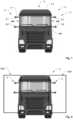
- Fig. 1shows a schematic front view of a utility vehicle V, specifically of a truck.
- the utility vehicle Vmay comprise a towing vehicle V1 and a trailer V2.
- the utility vehicle Vcomprises a camera system 1 for providing image information of the area at the left and right side next to the utility vehicle V and behind the trailer V2 of the utility vehicle V.
- the camera system 1comprises two pairs of cameras 2, 3, namely a first pair of cameras 2 arranged at the left side of the utility vehicle V and a second pair of cameras 3 arranged at the right side of the utility vehicle V.
- the first and second pair of cameras 2, 3comprise rear-viewing cameras, i.e. the main capturing direction of the cameras is opposite to the forward driving direction.
- the first pair of cameras 2provides image information of the left area next to and behind the utility vehicle V and the second pair of cameras 3 provides image information of the right area next to and behind the utility vehicle V.
- the images provided by the two pairs of cameras 2, 3provide information of the space at the left and right side of the utility vehicle V and the space behind the utility vehicle V which is not occluded by the towing vehicle V1 or the trailer V2.
- Each pair of cameras 2, 3comprises a first camera 2.1, 3.1 and a second camera 2.2, 3.2.
- the cameras of the pair of cameras 2, 3are arranged one above the other, as shown in Fig. 1 .
- the first cameras 2.1, 3.1build upper cameras which are arranged above and at a distance to the second cameras 2.2, 3.2, i.e. the second cameras 2.2, 3.2 build lower cameras, each second camera 2.2, 3.2 being arranged below a first camera 2.1, 3.1.
- the first cameras 2.1, 3.1are arranged at the left, respectively, right side of the cabin 4 at a height level equal or near to (e.g. 5 cm, 10cm or 20 cm lower) the top outer edge 4.1 of the cabin 4.
- the first cameras 2.1, 3.1 arranged at the left and right sidemay be arranged at the same height level.
- the height of the first cameras 2.1, 3.1may be in the range of 3.5m to 4m.
- the second cameras 2.2, 3.2are arranged at a height level equal or near to (e.g. 5 cm, 10cm or 20 cm lower) the lower edge 4.1 of the side window SW of the cabin 4.
- the second cameras 2.2, 3.2may be arranged at the height at which the lower edge of a rear view mirror is arranged.
- the second cameras 2.2, 3.2 arranged at the left and right sidemay be arranged at the same height level.
- the height of the second cameras 2.2, 3.2may be in the range of 2m to 2.5m, specifically at 2.1m, 2.2m, 2.3m or 2.4m.
- the cameras 2.1, 2.2, 3.1, 3.2are arranged by means of spacers 5 at the cabin 4.
- the spacers 5are configured to provide a horizontal distance between the outer cabin wall and the respective camera. Thereby, the occlusion due to the trailer can be reduced and the coverage range of the cameras 2.1, 2.2, 3.1, 3.2 can be increased.
- Each pair of cameras 2, 3forms a stereo camera system which is configured to determine distance information of detected objects by calculating a disparity map based on the pictures captured from both cameras and thereby developing a 3D point cloud.
- each stereo camera systemmay be configured to determine the speed of an object moving behind or at the respective side of the utility vehicle V.
- the cameras of the pair of cameras 2, 3have a vertical distance of at least 0.5m in order to obtain reliable distance information by the respective stereo camera system.
- the cameras 2.1, 2.2, 3.1, 3.2comprise a rectangular field of view FOV, i.e. the width of the field of view is smaller than the height of the field of view FOV.
- the cameras 2.1, 2.2, 3.1, 3.2provide image information in portrait view
- the vertical coverageis higher than the horizontal coverage which is suitable in most cases for monitoring the side and back area of the utility vehicle V.
- the cameras 2.1, 2.2, 3.1, 3.2may provide image information in landscape orientation, i.e. the width of the field of view may be greater than the height of the field of view FOV. Thereby a wider sideway field of view can be obtained which is beneficial for more narrow curve radii to be driven.
- the camerasmay provide grayscale-type image information.
- grayscale-type image informationinstead of coloured image information improves sensitivity and the possibility to use information of the camera system 1 also during night which is useful because in the side and back area there is no illumination by lamps of the ego-vehicle.
- Fig. 3shows a lateral view of a utility vehicle comprising the proposed camera system 1.
- the horizontal aperture angle of the cameras 2.1, 2.2, 3.1, 3.2may be between 15° and 25°, specifically 20° or essentially 20°.
- the vertical aperture angle of the cameras 2.1, 2.2, 3.1, 3.2may be between 25° and 35°, specifically 30° or essentially 30°.
- the cameras 2.1, 2.2, 3.1, 3.2may be aligned such that the inner image edge of the field of view FOV shows the side wall of the trailer V2 and field of view fans out laterally, as shown in Fig. 2 .
- Fig. 4shows a schematic block diagram of a camera system 1.
- the first pair of cameras 2is coupled with a first control unit 8 which is configured to provide a disparity map and a 3D point cloud of the left side area and back area next to the utility vehicle V.
- the second pair of cameras 3is coupled with a second control unit 9 which is configured to provide a disparity map and a 3D point cloud of the right side area and back area next to the utility vehicle V.
- the first and second control units 8, 9are coupled with a central control unit 10.
- the central control unit 10may combine information provided by the first and second control units 8, 9 and may derive information and/or may provide decisions based on information of the first and second control units 8, 9.
- the central control unit 10may be configured to perform object detection, extract obstacles and/or may determine driving decisions for autonomous driving functions.
- the camera system 1may only comprise a central control unit 10 and the functionality of the first and second control units 8, 9 may be integrated in said central control unit 10.
- the central control unit 10 and/or the first and second control units 8, 9implement a neural network for calculating stereo image information specifically a disparity map and 3D point cloud based on image information provided by the respective pair of cameras 2, 3.
- the neural networkis a trained neural network which has been trained by labelled training data.
- the training datamay be derived from real data, i.e. data captured in real driving situations and/or may be artificial training data.
- Fig. 6shows a camera system 1 configured to replace rear view mirrors of the utility vehicle attached at the at the outer side walls of the cabin 4.
- the first control unit 8may be coupled with a left rear view monitor 6 and the and second control unit 9 may be coupled with a right rear view monitor 7.
- the left rear view monitor 6is configured to display image information of the left side area and the left back area of the utility vehicle V thereby being able to remove the left rear view mirror.
- the right rear view monitor 7is configured to display image information of the right side area and the right back area of the utility vehicle V thereby being able to remove the right rear view mirror.
- the camera system 1may comprise a central display unit 11 for providing information obtained by the cameras 2.1, 2.2, 3.1, 3.2 to the driver.
- the detection range of the systemmight be reduced.
- nonlinear opticsthat implement a higher magnification in the centre of the image and lower magnification towards the border might be used in the cameras 2.1, 2.2, 3.1, 3.2.
- the central control unit 10may be configured to compensate said nonlinear magnification, i.e. calculate an image with equal magnification. Thereby, the viewing of images provided by the camera system is eased for human drives. However, an automated driving function might not require such equalization of magnification.
- the information regarding object distance and/or object speed derived by the stereo camera systemcan be used to highlight and/or apply such information to the respective objects in the respective rear view monitors 6, 7 and/or the display unit 11.
Landscapes
- Engineering & Computer Science (AREA)
- Multimedia (AREA)
- Theoretical Computer Science (AREA)
- Computer Vision & Pattern Recognition (AREA)
- Physics & Mathematics (AREA)
- General Physics & Mathematics (AREA)
- Mechanical Engineering (AREA)
- Health & Medical Sciences (AREA)
- Signal Processing (AREA)
- Artificial Intelligence (AREA)
- Computing Systems (AREA)
- Databases & Information Systems (AREA)
- Evolutionary Computation (AREA)
- General Health & Medical Sciences (AREA)
- Medical Informatics (AREA)
- Software Systems (AREA)
- Closed-Circuit Television Systems (AREA)
- Studio Devices (AREA)
Description
- The present invention relates generally to the field of camera systems. More specifically, the invention relates to a rear-view stereo camera system providing information of the left and right side areas and a back area behind a utility vehicle.
- Stereo camera systems in automotive applications are already known in order to provide image information of the scene in front of the ego-vehicle. The cameras are typically used in a horizontal arrangement, i.e. the cameras are arranged next to each other at a horizontal distance. Therefore, stereo cameras for automobile applications are usually optimized for a wide horizontal baseline.
- In the field of utility vehicles, specifically trucks comprising a towing vehicle and a trailer, the mounting of sensors on the rear end of the trailer for monitoring the rear space is not useful because the trailer can be changed and must therefore be compatible with different towing vehicles. On the other hand, the trailer limits the view of cameras arranged at the back side of the cabin of the towing vehicle. Document
US 2008/304705 A1 discloses a camera system for a utility vehicle and documentUS 2021/326694 A1 relates to distance determinations using neural networks.US 2021/350576 A1 discloses a camera system for a utility vehicle according to the preamble of claim 1. - It is an objective of the embodiments of the invention to provide a camera system for a utility vehicle which provides rear-view stereo camera images which can be used for capturing images of the side areas and back area of the utility vehicle, said images either be used by a human driver or by an autonomous driving system for taking driving decisions.
- The objective is solved by the features of independent claim 1. Preferred embodiments are given in the dependent claims. If not explicitly indicated otherwise, embodiments of the invention can be freely combined with each other.
- According to an aspect, the invention refers to a camera system for a utility vehicle. The camera system comprises two pairs of cameras. A first pair of cameras is arranged at the left side portion of the cabin of the utility vehicle, preferably at the front portion in the transition area between the front window and the left side window. A second pair of cameras is arranged at the right side portion of the cabin of the utility vehicle, preferably at the front portion in the transition area between the front window and the right side window. The cameras of the first and second pair of cameras are arranged one above the other in a vertical direction. The first pair of cameras builds a rear-viewing stereo camera system for providing image information and distance information of an area on the left side of the utility vehicle. The second pair of cameras builds a rear-viewing stereo camera system for providing image information and distance information of an area on the right side of the utility vehicle. The cameras of the first and second pair of cameras are arranged by means of one or more spacers at the cabin of the utility vehicle. The spacers provide a lateral distance of the cameras to the cabin, e.g. a distance of 10cm or more. The cameras of each pair of cameras have a vertical distance of at least 0.5m.
- Said camera system is advantageous because it provides image and distance information of objects besides and behind the utility vehicle independent of a potential trailer arranged at the utility vehicle and additionally reduces the occlusion caused by a trailer of the utility vehicle.
- According to an example embodiment, a first camera of the pairs of cameras is arranged as an upper camera in a height area between the top of the cabin and the upper edge of a side window of the cabin. Thereby, the upper camera provides image information from the top or essentially the top of the cabin which is advantageous for observing objects behind the utility vehicle and for obtaining a large distance between the upper and lower camera of the pair of cameras.
- According to an example embodiment, a second camera of the pairs of cameras is arranged as a lower camera in a height area between the upper edge of the side window and the lower edge of the side window. Thereby, the lower camera provides image information in a height which is advantageous for observing pedestrians or cyclists. In addition, a large distance between the upper and lower camera of the pair of cameras can be obtained.
- According to an example embodiment, a first camera of the pairs of cameras is arranged as an upper camera in a height range between 3.5m and 4m. Thereby the first cameras can provide an improved overview over the scene next to and behind the utility vehicle.
- According to an example embodiment, a second camera of the pairs of cameras is arranged as a lower camera in a height range between 2m and 3m. Thereby, a sufficient distance to the upper cameras can be provided and the perspective of the second camera is different to the perspective of the first camera which is advantageous for observing the area next to and behind the utility vehicle.
- According to the invention, the cameras comprise a rectangular or essentially rectangular field of view and the cameras are positioned to provide portrait view. In other words, the height of the field of view is greater than the width of the field of view. Thereby it is possible to reduce the blind spot of the camera system and adapt the field of view of the camera system to a vertically-aligned rectangular field of view. According to an example embodiment, the cameras provide a field of view with a vertical aperture angle in the range between 25° and 35° and a horizontal aperture angle in the range between 15° and 25°. Thereby, an improved observation of the area next to and behind the utility vehicle is possible.
- According to an example embodiment, the cameras are of greyscale type. Thereby it is possible to improve the sensitivity of the camera system and the operability at poor ambient light, e.g. in the evening or during the night because, in contrary to front-viewing cameras, there is no illumination of the area next to and behind the utility vehicle.
- According to another embodiment, the cameras may be infrared cameras or cameras of greyscale type which have a sensitivity in the infrared wavelength region. Thereby the sensitivity at night can be increased.
- According to an example embodiment, the first pair of cameras is configured to provide image information to a left rear view monitor and the second pair of cameras is configured to provide image information to a right rear view monitor for rear-view mirror replacement. Thereby, it is possible to use the camera system for monitoring the space next to and behind the utility vehicle similar to the left and right rear-view mirror and therefore remove the typically used rear-view mirrors attached to the cabin of the utility vehicle.
- According to an example embodiment, the cameras comprise a nonlinear optic with a higher magnification in the center portion of the field of view than in the peripheral area of the field of view. Thereby it is possible to improve the resolution of the camera in the central portion of the field of view in order to obtain a high detection range and the ability to distinguish objects at high distances in the area covered by the central portion of the field of view paired with a wide range of field of view which is necessary for obtaining a large observation coverage of the near space around the utility vehicle.
- According to an example embodiment, the camera system comprises a control unit configured to compensate the magnification difference between the center portion and the peripheral area of the field of view. Thereby it is possible to remove the nonlinearity of the camera optic and provide image information at a display or monitor with equal magnification in order to ease perceiving of image information for a human driver of the utility vehicle.
- According to an example embodiment, the camera system comprises a control unit configured to provide information regarding object speed and/or object distance of one or more objects arranged behind the camera system. Thereby, the camera system provides information which are useful for a human driver and/or a driving assistance system for taking driving decisions.
- According to an example embodiment, the camera system comprises a left rear view monitor and a right rear view monitor and/or a display unit configured to display rear view images. The control unit is configured to highlight objects provided at the left rear view monitor, the right rear view monitor and/or the display unit based on information regarding object speed and/or object distances of one or more objects arranged behind the camera system. By displaying said information on monitors and/or displays of the utility vehicle, the human driver can recognize said information associated with the respective object and take driving decisions based on said information.
- According to the invention, the camera system comprises a control unit which implements a trained neural network for calculating a disparity map and distance information to objects included in the image information provided by the cameras. Thereby, the quality of information provided by the stereo camera system can be improved.
- According to a further aspect, a utility vehicle comprising a camera system according to anyone of the preceding embodiments is disclosed.
- The term "utility vehicle" as used in the present disclosure may refer to a truck or any other vehicle designed to carry out a specific task. Specifically utility vehicle may refer to a semi which comprises a towing vehicle and a trailer.
- The term "essentially" or "approximately" as used in the invention means deviations from the exact value by +/- 10%, preferably by +/- 5% and/or deviations in the form of changes that are insignificant for the function and/or for the traffic laws.
- The various aspects of the invention, including its particular features and advantages, will be readily understood from the following detailed description and the accompanying drawings, in which:
Fig. 1 shows a schematic front view of a truck comprising a camera system;Fig. 2 schematically illustrates an example field of view of the pairs of cameras of the camera system;Fig. 3 schematically illustrates a side view of the truck and the vertical aperture of the field of view of the camera system;Fig. 4 schematically illustrates a block diagram of a first embodiment of the camera system;Fig. 5 schematically illustrates a block diagram of a second embodiment of the camera system; andFig. 6 schematically illustrates a block diagram of the camera system according toFig. 4 , the camera system additionally comprising monitors and/or a display for providing image information to the driver.- The present invention will now be described more fully with reference to the accompanying drawings, in which example embodiments are shown. The embodiments in the figures may relate to preferred embodiments, while all elements and features described in connection with embodiments may be used, as far as appropriate, in combination with any other embodiment and feature as discussed herein, in particular related to any other embodiment discussed further above. However, this invention should not be construed as limited to the embodiments set forth herein. Throughout the following description similar reference numerals have been used to denote similar elements, parts, items or features, when applicable.
Fig. 1 shows a schematic front view of a utility vehicle V, specifically of a truck. The utility vehicle V may comprise a towing vehicle V1 and a trailer V2. The utility vehicle V comprises a camera system 1 for providing image information of the area at the left and right side next to the utility vehicle V and behind the trailer V2 of the utility vehicle V.- The camera system 1 comprises two pairs of
cameras cameras 2 arranged at the left side of the utility vehicle V and a second pair ofcameras 3 arranged at the right side of the utility vehicle V. The first and second pair ofcameras cameras 2 provides image information of the left area next to and behind the utility vehicle V and the second pair ofcameras 3 provides image information of the right area next to and behind the utility vehicle V. Thereby the images provided by the two pairs ofcameras - Each pair of
cameras cameras Fig. 1 . The first cameras 2.1, 3.1 build upper cameras which are arranged above and at a distance to the second cameras 2.2, 3.2, i.e. the second cameras 2.2, 3.2 build lower cameras, each second camera 2.2, 3.2 being arranged below a first camera 2.1, 3.1. - As shown in
Fig. 1, 2 and3 , the first cameras 2.1, 3.1 are arranged at the left, respectively, right side of thecabin 4 at a height level equal or near to (e.g. 5 cm, 10cm or 20 cm lower) the top outer edge 4.1 of thecabin 4. The first cameras 2.1, 3.1 arranged at the left and right side may be arranged at the same height level. For example, referring to ground level, the height of the first cameras 2.1, 3.1 may be in the range of 3.5m to 4m. - Furthermore, the second cameras 2.2, 3.2 are arranged at a height level equal or near to (e.g. 5 cm, 10cm or 20 cm lower) the lower edge 4.1 of the side window SW of the
cabin 4. In other words, the second cameras 2.2, 3.2 may be arranged at the height at which the lower edge of a rear view mirror is arranged. The second cameras 2.2, 3.2 arranged at the left and right side may be arranged at the same height level. For example, referring to ground level, the height of the second cameras 2.2, 3.2 may be in the range of 2m to 2.5m, specifically at 2.1m, 2.2m, 2.3m or 2.4m. - As shown in
Fig. 1 and 2 , the cameras 2.1, 2.2, 3.1, 3.2 are arranged by means ofspacers 5 at thecabin 4. Thespacers 5 are configured to provide a horizontal distance between the outer cabin wall and the respective camera. Thereby, the occlusion due to the trailer can be reduced and the coverage range of the cameras 2.1, 2.2, 3.1, 3.2 can be increased. - Each pair of
cameras - The cameras of the pair of
cameras - As shown in
Fig. 2 , the cameras 2.1, 2.2, 3.1, 3.2 comprise a rectangular field of view FOV, i.e. the width of the field of view is smaller than the height of the field of view FOV. In other words, the cameras 2.1, 2.2, 3.1, 3.2 provide image information in portrait view Thereby, the vertical coverage is higher than the horizontal coverage which is suitable in most cases for monitoring the side and back area of the utility vehicle V. - However, according to another embodiment that does not belong to the invention, the cameras 2.1, 2.2, 3.1, 3.2 may provide image information in landscape orientation, i.e. the width of the field of view may be greater than the height of the field of view FOV. Thereby a wider sideway field of view can be obtained which is beneficial for more narrow curve radii to be driven.
- The cameras may provide grayscale-type image information. Using grayscale-type image information instead of coloured image information improves sensitivity and the possibility to use information of the camera system 1 also during night which is useful because in the side and back area there is no illumination by lamps of the ego-vehicle.
Fig. 3 shows a lateral view of a utility vehicle comprising the proposed camera system 1. The horizontal aperture angle of the cameras 2.1, 2.2, 3.1, 3.2 may be between 15° and 25°, specifically 20° or essentially 20°. The vertical aperture angle of the cameras 2.1, 2.2, 3.1, 3.2 may be between 25° and 35°, specifically 30° or essentially 30°.- The cameras 2.1, 2.2, 3.1, 3.2 may be aligned such that the inner image edge of the field of view FOV shows the side wall of the trailer V2 and field of view fans out laterally, as shown in
Fig. 2 . Fig. 4 shows a schematic block diagram of a camera system 1. The first pair ofcameras 2 is coupled with afirst control unit 8 which is configured to provide a disparity map and a 3D point cloud of the left side area and back area next to the utility vehicle V. The second pair ofcameras 3 is coupled with asecond control unit 9 which is configured to provide a disparity map and a 3D point cloud of the right side area and back area next to the utility vehicle V.- The first and
second control units central control unit 10. Thecentral control unit 10 may combine information provided by the first andsecond control units second control units central control unit 10 may be configured to perform object detection, extract obstacles and/or may determine driving decisions for autonomous driving functions. - However, in another embodiment, as shown in
Fig. 5 , the camera system 1 may only comprise acentral control unit 10 and the functionality of the first andsecond control units central control unit 10. - The
central control unit 10 and/or the first andsecond control units cameras Fig. 6 shows a camera system 1 configured to replace rear view mirrors of the utility vehicle attached at the at the outer side walls of thecabin 4. Thefirst control unit 8 may be coupled with a leftrear view monitor 6 and the andsecond control unit 9 may be coupled with a rightrear view monitor 7. The leftrear view monitor 6 is configured to display image information of the left side area and the left back area of the utility vehicle V thereby being able to remove the left rear view mirror. Similarly, the rightrear view monitor 7 is configured to display image information of the right side area and the right back area of the utility vehicle V thereby being able to remove the right rear view mirror.- Additionally or for replacing left and right rear view monitors 6, 7, the camera system 1 may comprise a
central display unit 11 for providing information obtained by the cameras 2.1, 2.2, 3.1, 3.2 to the driver. - In order to obtain the required solution, obtain the required lateral width of field of view and being able to detect small objects at far distances, the detection range of the system might be reduced. In addition, nonlinear optics that implement a higher magnification in the centre of the image and lower magnification towards the border might be used in the cameras 2.1, 2.2, 3.1, 3.2. The
central control unit 10 may be configured to compensate said nonlinear magnification, i.e. calculate an image with equal magnification. Thereby, the viewing of images provided by the camera system is eased for human drives. However, an automated driving function might not require such equalization of magnification. - The information regarding object distance and/or object speed derived by the stereo camera system can be used to highlight and/or apply such information to the respective objects in the respective rear view monitors 6, 7 and/or the
display unit 11. - It should be noted that the description and drawings merely illustrate the principles of the proposed invention. Those skilled in the art will be able to implement various arrangements that, although not explicitly described or shown herein, embody the principles of the invention as defined by the claims.
- 1
- camera system
- 2
- first pair of cameras
- 2.1
- upper camera
- 2.2
- lower camera
- 3
- second pair of cameras
- 3.1
- upper camera
- 3.2
- lower camera
- 4
- cabin
- 4.1
- top edge
- 5
- spacer
- 6
- left rear view monitor
- 7
- right rear view monitor
- 8
- first control unit
- 9
- second control unit
- 10
- central control unit
- 11
- display unit
- FOV
- field of view
- FW
- front window
- SW
- side window
- V
- Vehicle
- V1
- towing vehicle
- V2
- trailer
Claims (13)
- Camera system for a utility vehicle (V) having a cabin (4), the camera system (1) comprising two pairs of cameras (2, 3), wherein a first pair of cameras (2) is arranged at the left side portion of the cabin (4) of the utility vehicle (V) and a second pair of cameras (3) is arranged at the right side portion of the cabin (4) of the utility vehicle (V), wherein the cameras (2.1, 2.2, 3.1, 3.2) of the first and second pair of cameras (2, 3) are arranged one above the other in a vertical direction, wherein the first pair of cameras (2) builds a rear-viewing stereo camera system for providing image information and distance information of an area on the left side of the utility vehicle (V) and the second pair of cameras (3) builds a rear-viewing stereo camera system for providing image information and distance information of an area on the right side of the utility vehicle (V), wherein the cameras (2.1, 2.2, 3.1, 3.2) of the first and second pair of cameras (2, 3) are arranged by means of one or more spacers (5) at the cabin (4) of the utility vehicle (V), the spacers (5) providing a lateral distance of the cameras (2.1, 2.2, 3.1, 3.2) to the cabin (4) and wherein the cameras (2.1, 2.2, 3.1, 3.2) of each pair of cameras (2, 3) have a vertical distance of at least 0.5m,characterized in that the cameras (2.1, 2.2, 3.1, 3.2) comprise a rectangular or essentially rectangular field of view andin that the cameras (2.1, 2.2, 3.1, 3.2) are positioned to provide portrait view, andin that it comprises a control unit (8, 9, 10) implementing a trained neural network for calculating a disparity map and distance information to objects included in the image information provided by the cameras (2.1, 2.2, 3.1, 3.2).
- Camera system according to claim 1, wherein a first camera (2.1, 3.1) of the pairs of cameras (2, 3) is arranged as an upper camera in a height area between the top of the cabin (4) and the upper edge of a side window (SW) of the cabin (4).
- Camera system according to claim 1 or 2, wherein a second camera (2.2, 3.2) of the pairs of cameras (2, 3) is arranged as a lower camera in a height area between the upper edge of a side window (SW) and the lower edge of a side window (SW).
- Camera system according to any of the preceding claims, wherein a first camera (2.1, 3.1) of the pairs of cameras (2, 3) is arranged as an upper camera in a height range between 3.5m and 4m.
- Camera system according to any of the preceding claims, wherein a second camera (2.2, 3.3) of the pairs of cameras (2, 3) is arranged as a lower camera in a height range between 2m and 3m.
- Camera system according to any of the preceding claims, wherein the cameras (2.1, 2.2, 3.1, 3.2) provide a field-of-view with a vertical aperture angle in the range between 25° and 35° and a horizontal aperture angle in the range between 15° and 25°.
- Camera system according to anyone of preceding claims, wherein the cameras (2.1, 2.2, 3.1, 3.2) are of greyscale type.
- Camera system according to anyone of preceding claims, wherein the first pair of cameras (2) is configured to provide image information to a left rear view monitor (6) and the second pair of cameras (3) is configured to provide image information to a right rear view monitor (7) for rear-view mirror replacement.
- Camera system according to anyone of preceding claims, wherein the cameras (2.1, 2.2, 3.1, 3.2) comprise a nonlinear optic with a higher magnification in the center portion of the field of view (FOV) than in the peripheral area of the field of view (FOV).
- Camera system according to claim 9, wherein the camera system (1) comprises a control unit (8, 9, 10) configured to compensate the magnification difference between the center portion and the peripheral area of the field of view (FOV).
- Camera system according to anyone of preceding claims, wherein the camera system (1) comprises a control unit (8, 9, 10) configured to provide information regarding object speed and/or object distances of one or more objects arranged behind the camera system (1).
- Camera system according to claim 11, wherein the camera system (1) comprises a left rear view monitor (6) and a right rear view monitor (7) and/or a display unit (11) configured to display rear view images and wherein the control unit (8, 9, 10) is configured to highlight objects provided at the left rear view monitor (6), the right rear view monitor (7) and/or the display unit (11) based on information regarding object speed and/or object distances of one or more objects arranged behind the camera system (1).
- Utility vehicle comprising a camera system (1) according to anyone of the preceding claims.
Priority Applications (2)
| Application Number | Priority Date | Filing Date | Title |
|---|---|---|---|
| EP22155749.9AEP4223593B1 (en) | 2022-02-08 | 2022-02-08 | Rear-view stereo camera system |
| US18/166,293US20230252793A1 (en) | 2022-02-08 | 2023-02-08 | Rear-view stereo camera system |
Applications Claiming Priority (1)
| Application Number | Priority Date | Filing Date | Title |
|---|---|---|---|
| EP22155749.9AEP4223593B1 (en) | 2022-02-08 | 2022-02-08 | Rear-view stereo camera system |
Publications (2)
| Publication Number | Publication Date |
|---|---|
| EP4223593A1 EP4223593A1 (en) | 2023-08-09 |
| EP4223593B1true EP4223593B1 (en) | 2025-01-01 |
Family
ID=80446570
Family Applications (1)
| Application Number | Title | Priority Date | Filing Date |
|---|---|---|---|
| EP22155749.9AActiveEP4223593B1 (en) | 2022-02-08 | 2022-02-08 | Rear-view stereo camera system |
Country Status (2)
| Country | Link |
|---|---|
| US (1) | US20230252793A1 (en) |
| EP (1) | EP4223593B1 (en) |
Families Citing this family (1)
| Publication number | Priority date | Publication date | Assignee | Title |
|---|---|---|---|---|
| CN117237393B (en)* | 2023-11-06 | 2024-05-17 | 深圳金语科技有限公司 | Image processing method and device based on streaming media rearview mirror and computer equipment |
Family Cites Families (6)
| Publication number | Priority date | Publication date | Assignee | Title |
|---|---|---|---|---|
| US8199975B2 (en)* | 2006-12-12 | 2012-06-12 | Cognex Corporation | System and method for side vision detection of obstacles for vehicles |
| EP2784763A4 (en)* | 2011-11-25 | 2015-08-19 | Honda Motor Co Ltd | Vehicle periphery monitoring device |
| EP3010761B1 (en)* | 2013-06-21 | 2019-07-24 | Magna Electronics Inc. | Vehicle vision system |
| DE102019213607A1 (en)* | 2019-09-06 | 2021-03-11 | Continental Automotive Gmbh | 3D display in digital vehicle rearview mirror |
| KR102550678B1 (en)* | 2020-01-22 | 2023-07-04 | 노다르 인크. | Non-Rigid Stereo Vision Camera System |
| US20210326694A1 (en)* | 2020-04-20 | 2021-10-21 | Nvidia Corporation | Distance determinations using one or more neural networks |
- 2022
- 2022-02-08EPEP22155749.9Apatent/EP4223593B1/enactiveActive
- 2023
- 2023-02-08USUS18/166,293patent/US20230252793A1/enactivePending
Also Published As
| Publication number | Publication date |
|---|---|
| EP4223593A1 (en) | 2023-08-09 |
| US20230252793A1 (en) | 2023-08-10 |
Similar Documents
| Publication | Publication Date | Title |
|---|---|---|
| US11794647B2 (en) | Vehicular vision system having a plurality of cameras | |
| US12001213B2 (en) | Vehicle and trailer maneuver assist system | |
| US11505123B2 (en) | Vehicular camera monitoring system with stereographic display | |
| US11472338B2 (en) | Method for displaying reduced distortion video images via a vehicular vision system | |
| US10183621B2 (en) | Vehicular image processing apparatus and vehicular image processing system | |
| US20200148114A1 (en) | Vehicular vision system with reduced distortion display | |
| US8537221B2 (en) | Lane change control system | |
| US20070206835A1 (en) | Method of Processing Images Photographed by Plural Cameras And Apparatus For The Same | |
| US20160094808A1 (en) | All-round view monitoring system for a motor vehicle | |
| CN101396989A (en) | Vehicle periphery monitoring apparatus and image displaying method | |
| US20170347036A1 (en) | Driver Assistance System | |
| US20080198227A1 (en) | Night Vision System | |
| US11377027B2 (en) | Image processing apparatus, imaging apparatus, driving assistance apparatus, mobile body, and image processing method | |
| JP7028536B2 (en) | Display system | |
| EP4395356A1 (en) | Image capturing device, movable apparatus, and storage medium | |
| US11584299B2 (en) | Driver-assisting system for an industrial vehicle | |
| EP4223593B1 (en) | Rear-view stereo camera system | |
| US11400861B2 (en) | Camera monitoring system | |
| EP2902262B1 (en) | A camera arrangement, a system including a camera arrangement and a vehicle including a camera arrangement | |
| US10889245B2 (en) | Vehicle imaging system | |
| KR20220161611A (en) | AVM system with point-of-view function | |
| JP2019110390A (en) | Vehicle periphery monitoring device | |
| KR20250069426A (en) | Camera-based system and method for determining and verifying the position of a trailer |
Legal Events
| Date | Code | Title | Description |
|---|---|---|---|
| PUAI | Public reference made under article 153(3) epc to a published international application that has entered the european phase | Free format text:ORIGINAL CODE: 0009012 | |
| STAA | Information on the status of an ep patent application or granted ep patent | Free format text:STATUS: THE APPLICATION HAS BEEN PUBLISHED | |
| AK | Designated contracting states | Kind code of ref document:A1 Designated state(s):AL AT BE BG CH CY CZ DE DK EE ES FI FR GB GR HR HU IE IS IT LI LT LU LV MC MK MT NL NO PL PT RO RS SE SI SK SM TR | |
| STAA | Information on the status of an ep patent application or granted ep patent | Free format text:STATUS: REQUEST FOR EXAMINATION WAS MADE | |
| STAA | Information on the status of an ep patent application or granted ep patent | Free format text:STATUS: EXAMINATION IS IN PROGRESS | |
| 17P | Request for examination filed | Effective date:20240209 | |
| RBV | Designated contracting states (corrected) | Designated state(s):AL AT BE BG CH CY CZ DE DK EE ES FI FR GB GR HR HU IE IS IT LI LT LU LV MC MK MT NL NO PL PT RO RS SE SI SK SM TR | |
| 17Q | First examination report despatched | Effective date:20240304 | |
| GRAP | Despatch of communication of intention to grant a patent | Free format text:ORIGINAL CODE: EPIDOSNIGR1 | |
| STAA | Information on the status of an ep patent application or granted ep patent | Free format text:STATUS: GRANT OF PATENT IS INTENDED | |
| INTG | Intention to grant announced | Effective date:20240731 | |
| GRAS | Grant fee paid | Free format text:ORIGINAL CODE: EPIDOSNIGR3 | |
| GRAA | (expected) grant | Free format text:ORIGINAL CODE: 0009210 | |
| STAA | Information on the status of an ep patent application or granted ep patent | Free format text:STATUS: THE PATENT HAS BEEN GRANTED | |
| AK | Designated contracting states | Kind code of ref document:B1 Designated state(s):AL AT BE BG CH CY CZ DE DK EE ES FI FR GB GR HR HU IE IS IT LI LT LU LV MC MK MT NL NO PL PT RO RS SE SI SK SM TR | |
| REG | Reference to a national code | Ref country code:GB Ref legal event code:FG4D | |
| REG | Reference to a national code | Ref country code:CH Ref legal event code:EP | |
| REG | Reference to a national code | Ref country code:DE Ref legal event code:R096 Ref document number:602022009204 Country of ref document:DE | |
| REG | Reference to a national code | Ref country code:IE Ref legal event code:FG4D | |
| PGFP | Annual fee paid to national office [announced via postgrant information from national office to epo] | Ref country code:DE Payment date:20250228 Year of fee payment:4 | |
| PGFP | Annual fee paid to national office [announced via postgrant information from national office to epo] | Ref country code:AT Payment date:20250417 Year of fee payment:4 | |
| REG | Reference to a national code | Ref country code:LT Ref legal event code:MG9D | |
| REG | Reference to a national code | Ref country code:NL Ref legal event code:MP Effective date:20250101 | |
| REG | Reference to a national code | Ref country code:AT Ref legal event code:MK05 Ref document number:1755937 Country of ref document:AT Kind code of ref document:T Effective date:20250101 | |
| PG25 | Lapsed in a contracting state [announced via postgrant information from national office to epo] | Ref country code:NL Free format text:LAPSE BECAUSE OF FAILURE TO SUBMIT A TRANSLATION OF THE DESCRIPTION OR TO PAY THE FEE WITHIN THE PRESCRIBED TIME-LIMIT Effective date:20250101 | |
| PG25 | Lapsed in a contracting state [announced via postgrant information from national office to epo] | Ref country code:FI Free format text:LAPSE BECAUSE OF FAILURE TO SUBMIT A TRANSLATION OF THE DESCRIPTION OR TO PAY THE FEE WITHIN THE PRESCRIBED TIME-LIMIT Effective date:20250101 | |
| PG25 | Lapsed in a contracting state [announced via postgrant information from national office to epo] | Ref country code:PL Free format text:LAPSE BECAUSE OF FAILURE TO SUBMIT A TRANSLATION OF THE DESCRIPTION OR TO PAY THE FEE WITHIN THE PRESCRIBED TIME-LIMIT Effective date:20250101 | |
| PG25 | Lapsed in a contracting state [announced via postgrant information from national office to epo] | Ref country code:ES Free format text:LAPSE BECAUSE OF FAILURE TO SUBMIT A TRANSLATION OF THE DESCRIPTION OR TO PAY THE FEE WITHIN THE PRESCRIBED TIME-LIMIT Effective date:20250101 | |
| REG | Reference to a national code | Ref country code:DE Ref legal event code:R081 Ref document number:602022009204 Country of ref document:DE Owner name:AUMOVIO AUTONOMOUS MOBILITY GERMANY GMBH, DE Free format text:FORMER OWNER: CONTINENTAL AUTONOMOUS MOBILITY GERMANY GMBH, 85057 INGOLSTADT, DE | |
| PG25 | Lapsed in a contracting state [announced via postgrant information from national office to epo] | Ref country code:IS Free format text:LAPSE BECAUSE OF FAILURE TO SUBMIT A TRANSLATION OF THE DESCRIPTION OR TO PAY THE FEE WITHIN THE PRESCRIBED TIME-LIMIT Effective date:20250501 Ref country code:NO Free format text:LAPSE BECAUSE OF FAILURE TO SUBMIT A TRANSLATION OF THE DESCRIPTION OR TO PAY THE FEE WITHIN THE PRESCRIBED TIME-LIMIT Effective date:20250401 | |
| PG25 | Lapsed in a contracting state [announced via postgrant information from national office to epo] | Ref country code:HR Free format text:LAPSE BECAUSE OF FAILURE TO SUBMIT A TRANSLATION OF THE DESCRIPTION OR TO PAY THE FEE WITHIN THE PRESCRIBED TIME-LIMIT Effective date:20250101 | |
| PG25 | Lapsed in a contracting state [announced via postgrant information from national office to epo] | Ref country code:LV Free format text:LAPSE BECAUSE OF FAILURE TO SUBMIT A TRANSLATION OF THE DESCRIPTION OR TO PAY THE FEE WITHIN THE PRESCRIBED TIME-LIMIT Effective date:20250101 Ref country code:PT Free format text:LAPSE BECAUSE OF FAILURE TO SUBMIT A TRANSLATION OF THE DESCRIPTION OR TO PAY THE FEE WITHIN THE PRESCRIBED TIME-LIMIT Effective date:20250502 | |
| PG25 | Lapsed in a contracting state [announced via postgrant information from national office to epo] | Ref country code:BG Free format text:LAPSE BECAUSE OF FAILURE TO SUBMIT A TRANSLATION OF THE DESCRIPTION OR TO PAY THE FEE WITHIN THE PRESCRIBED TIME-LIMIT Effective date:20250101 Ref country code:GR Free format text:LAPSE BECAUSE OF FAILURE TO SUBMIT A TRANSLATION OF THE DESCRIPTION OR TO PAY THE FEE WITHIN THE PRESCRIBED TIME-LIMIT Effective date:20250402 | |
| PG25 | Lapsed in a contracting state [announced via postgrant information from national office to epo] | Ref country code:AT Free format text:LAPSE BECAUSE OF FAILURE TO SUBMIT A TRANSLATION OF THE DESCRIPTION OR TO PAY THE FEE WITHIN THE PRESCRIBED TIME-LIMIT Effective date:20250101 | |
| PG25 | Lapsed in a contracting state [announced via postgrant information from national office to epo] | Ref country code:CZ Free format text:LAPSE BECAUSE OF FAILURE TO SUBMIT A TRANSLATION OF THE DESCRIPTION OR TO PAY THE FEE WITHIN THE PRESCRIBED TIME-LIMIT Effective date:20250101 | |
| RAP4 | Party data changed (patent owner data changed or rights of a patent transferred) | Owner name:AUMOVIO AUTONOMOUS MOBILITY GERMANY GMBH | |
| PG25 | Lapsed in a contracting state [announced via postgrant information from national office to epo] | Ref country code:SE Free format text:LAPSE BECAUSE OF FAILURE TO SUBMIT A TRANSLATION OF THE DESCRIPTION OR TO PAY THE FEE WITHIN THE PRESCRIBED TIME-LIMIT Effective date:20250101 | |
| REG | Reference to a national code | Ref country code:CH Ref legal event code:PL | |
| PG25 | Lapsed in a contracting state [announced via postgrant information from national office to epo] | Ref country code:SM Free format text:LAPSE BECAUSE OF FAILURE TO SUBMIT A TRANSLATION OF THE DESCRIPTION OR TO PAY THE FEE WITHIN THE PRESCRIBED TIME-LIMIT Effective date:20250101 |