EP4218610B1 - Surgical introducer with guidance system receptacle - Google Patents
Surgical introducer with guidance system receptacleDownload PDFInfo
- Publication number
- EP4218610B1 EP4218610B1EP23165657.0AEP23165657AEP4218610B1EP 4218610 B1EP4218610 B1EP 4218610B1EP 23165657 AEP23165657 AEP 23165657AEP 4218610 B1EP4218610 B1EP 4218610B1
- Authority
- EP
- European Patent Office
- Prior art keywords
- introducer
- probe
- receiver
- receptacle
- lock
- Prior art date
- Legal status (The legal status is an assumption and is not a legal conclusion. Google has not performed a legal analysis and makes no representation as to the accuracy of the status listed.)
- Active
Links
Images


Classifications
- A—HUMAN NECESSITIES
- A61—MEDICAL OR VETERINARY SCIENCE; HYGIENE
- A61B—DIAGNOSIS; SURGERY; IDENTIFICATION
- A61B17/00—Surgical instruments, devices or methods
- A61B17/02—Surgical instruments, devices or methods for holding wounds open, e.g. retractors; Tractors
- A61B17/0218—Surgical instruments, devices or methods for holding wounds open, e.g. retractors; Tractors for minimally invasive surgery
- A—HUMAN NECESSITIES
- A61—MEDICAL OR VETERINARY SCIENCE; HYGIENE
- A61B—DIAGNOSIS; SURGERY; IDENTIFICATION
- A61B34/00—Computer-aided surgery; Manipulators or robots specially adapted for use in surgery
- A61B34/20—Surgical navigation systems; Devices for tracking or guiding surgical instruments, e.g. for frameless stereotaxis
- A—HUMAN NECESSITIES
- A61—MEDICAL OR VETERINARY SCIENCE; HYGIENE
- A61B—DIAGNOSIS; SURGERY; IDENTIFICATION
- A61B17/00—Surgical instruments, devices or methods
- A61B17/02—Surgical instruments, devices or methods for holding wounds open, e.g. retractors; Tractors
- A—HUMAN NECESSITIES
- A61—MEDICAL OR VETERINARY SCIENCE; HYGIENE
- A61B—DIAGNOSIS; SURGERY; IDENTIFICATION
- A61B17/00—Surgical instruments, devices or methods
- A61B17/34—Trocars; Puncturing needles
- A61B17/3417—Details of tips or shafts, e.g. grooves, expandable, bendable; Multiple coaxial sliding cannulas, e.g. for dilating
- A61B17/3421—Cannulas
- A61B17/3439—Cannulas with means for changing the inner diameter of the cannula, e.g. expandable
- A—HUMAN NECESSITIES
- A61—MEDICAL OR VETERINARY SCIENCE; HYGIENE
- A61B—DIAGNOSIS; SURGERY; IDENTIFICATION
- A61B90/00—Instruments, implements or accessories specially adapted for surgery or diagnosis and not covered by any of the groups A61B1/00 - A61B50/00, e.g. for luxation treatment or for protecting wound edges
- A61B90/36—Image-producing devices or illumination devices not otherwise provided for
- A61B90/361—Image-producing devices, e.g. surgical cameras
- A—HUMAN NECESSITIES
- A61—MEDICAL OR VETERINARY SCIENCE; HYGIENE
- A61B—DIAGNOSIS; SURGERY; IDENTIFICATION
- A61B90/00—Instruments, implements or accessories specially adapted for surgery or diagnosis and not covered by any of the groups A61B1/00 - A61B50/00, e.g. for luxation treatment or for protecting wound edges
- A61B90/39—Markers, e.g. radio-opaque or breast lesions markers
- A—HUMAN NECESSITIES
- A61—MEDICAL OR VETERINARY SCIENCE; HYGIENE
- A61B—DIAGNOSIS; SURGERY; IDENTIFICATION
- A61B17/00—Surgical instruments, devices or methods
- A61B2017/0046—Surgical instruments, devices or methods with a releasable handle; with handle and operating part separable
- A—HUMAN NECESSITIES
- A61—MEDICAL OR VETERINARY SCIENCE; HYGIENE
- A61B—DIAGNOSIS; SURGERY; IDENTIFICATION
- A61B17/00—Surgical instruments, devices or methods
- A61B2017/00831—Material properties
- A61B2017/00902—Material properties transparent or translucent
- A61B2017/00907—Material properties transparent or translucent for light
- A—HUMAN NECESSITIES
- A61—MEDICAL OR VETERINARY SCIENCE; HYGIENE
- A61B—DIAGNOSIS; SURGERY; IDENTIFICATION
- A61B17/00—Surgical instruments, devices or methods
- A61B17/34—Trocars; Puncturing needles
- A61B2017/347—Locking means, e.g. for locking instrument in cannula
- A—HUMAN NECESSITIES
- A61—MEDICAL OR VETERINARY SCIENCE; HYGIENE
- A61B—DIAGNOSIS; SURGERY; IDENTIFICATION
- A61B34/00—Computer-aided surgery; Manipulators or robots specially adapted for use in surgery
- A61B34/20—Surgical navigation systems; Devices for tracking or guiding surgical instruments, e.g. for frameless stereotaxis
- A61B2034/2046—Tracking techniques
- A61B2034/2051—Electromagnetic tracking systems
- A—HUMAN NECESSITIES
- A61—MEDICAL OR VETERINARY SCIENCE; HYGIENE
- A61B—DIAGNOSIS; SURGERY; IDENTIFICATION
- A61B34/00—Computer-aided surgery; Manipulators or robots specially adapted for use in surgery
- A61B34/20—Surgical navigation systems; Devices for tracking or guiding surgical instruments, e.g. for frameless stereotaxis
- A61B2034/2046—Tracking techniques
- A61B2034/2055—Optical tracking systems
- A—HUMAN NECESSITIES
- A61—MEDICAL OR VETERINARY SCIENCE; HYGIENE
- A61B—DIAGNOSIS; SURGERY; IDENTIFICATION
- A61B34/00—Computer-aided surgery; Manipulators or robots specially adapted for use in surgery
- A61B34/20—Surgical navigation systems; Devices for tracking or guiding surgical instruments, e.g. for frameless stereotaxis
- A61B2034/2068—Surgical navigation systems; Devices for tracking or guiding surgical instruments, e.g. for frameless stereotaxis using pointers, e.g. pointers having reference marks for determining coordinates of body points
- A—HUMAN NECESSITIES
- A61—MEDICAL OR VETERINARY SCIENCE; HYGIENE
- A61B—DIAGNOSIS; SURGERY; IDENTIFICATION
- A61B90/00—Instruments, implements or accessories specially adapted for surgery or diagnosis and not covered by any of the groups A61B1/00 - A61B50/00, e.g. for luxation treatment or for protecting wound edges
- A61B90/39—Markers, e.g. radio-opaque or breast lesions markers
- A61B2090/3937—Visible markers
- A61B2090/3945—Active visible markers, e.g. light emitting diodes
- A—HUMAN NECESSITIES
- A61—MEDICAL OR VETERINARY SCIENCE; HYGIENE
- A61B—DIAGNOSIS; SURGERY; IDENTIFICATION
- A61B90/00—Instruments, implements or accessories specially adapted for surgery or diagnosis and not covered by any of the groups A61B1/00 - A61B50/00, e.g. for luxation treatment or for protecting wound edges
- A61B90/39—Markers, e.g. radio-opaque or breast lesions markers
- A61B2090/3954—Markers, e.g. radio-opaque or breast lesions markers magnetic, e.g. NMR or MRI
- A61B2090/3958—Markers, e.g. radio-opaque or breast lesions markers magnetic, e.g. NMR or MRI emitting a signal
- A—HUMAN NECESSITIES
- A61—MEDICAL OR VETERINARY SCIENCE; HYGIENE
- A61B—DIAGNOSIS; SURGERY; IDENTIFICATION
- A61B90/00—Instruments, implements or accessories specially adapted for surgery or diagnosis and not covered by any of the groups A61B1/00 - A61B50/00, e.g. for luxation treatment or for protecting wound edges
- A61B90/39—Markers, e.g. radio-opaque or breast lesions markers
- A61B2090/3983—Reference marker arrangements for use with image guided surgery
- A—HUMAN NECESSITIES
- A61—MEDICAL OR VETERINARY SCIENCE; HYGIENE
- A61B—DIAGNOSIS; SURGERY; IDENTIFICATION
- A61B2217/00—General characteristics of surgical instruments
- A61B2217/002—Auxiliary appliance
Definitions
- the present inventionrelates to delicate tissue surgical retractor systems for use in the brain or other tissue susceptible to retraction injury.
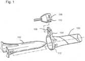
- Figure 1 of this publicationillustrates a soft tissue retractor system having a hollow retractor 100, and an introducer 102 that is selectively inserted into the retractor 100.
- the retractor 100 and/or introducer 102may include a handle 104 to facilitate manipulation and placement of the retractor system, and a lock to hold the introducer and retractor together.
- the handle 104is configured to connect to a clamp 106, such as the standard surgical clamp 106 shown in Figure 1 .
- the device in Figure 1(with some modifications) is commercially sold as the "VBAS" device by Vycor Medical, Inc. of Boca Raton, Florida.
- a retractor system such as shown in Figure 1is often used by inserting the introducer 102 into the retractor 100 and locking it in place, so the two can be moved and manipulated as a unit.
- the combined retractor systemis inserted into the patient's body and moved to the surgery site, and then the introducer 102 is unlocked and removed to permit access to the site through the retractor 100.
- the handle 104may be locked to a clamp 106 to hold the retractor 100 in place. Surgeons using this retractor sometimes do not use a clamp to hold the retractor at the surgery site, and often manually manipulate the retractor to access different parts of the surgery site during the surgical procedure.
- the retractor system and the retractormay be manipulated by holding the proximal ends of the introducer or retractor or by holding the handle.
- the device shown in Figure 1may have a transparent introducer 102 and/or retractor 100, and surgeons using such devices advantageously use the transparent introducer and retractor to observe the underlying tissue and to visually guide the unit to the surgery site. While it has been found that visual guidance by looking through the introducer 102 is very beneficial, it also has been found that some form of additional guidance or navigation may be desired in some cases. For example, in some cases, surgeons have used a probe or guide wire (a narrow elongated rod) to guide the movement of the retractor system. In such cases, the probe is advanced to the surgery site, and then the interlocked retractor system is slid over the probe until it reaches the surgery site. This is facilitated by the inclusion of a hole at the tip of the introducer that fits around the probe.
- a probe or guide wirea narrow elongated rod
- the probemay include a so-called "starburst" or the like, on the probe's proximal end (i.e., the end opposite the distal end that is inserted to the surgical site).
- This and other navigation systemsare known in the art.
- frameless navigation systems and other computerized guidance systems and methodsare described in U.S. Publication No. 2001/0027271 and others, and are commercially available from companies such as Medtronic, Inc., Stryker, BrainLab, AG, and GE Healthcare.
- “computerized guidance”encompasses any method of guiding a device to or at a surgical site that relies on computer visualization and/or control.
- United States Patent Publication Number 2010/0010315briefly notes the possibility of using stereotactic guidance or navigation in conjunction with a surgical retractor, but does not illustrate or describe this procedure or any apparatus for accomplishing this objective. Nevertheless, surgeons have been known to use a navigation probe "freehand" with a VBAS device such as shown in Figure 1 . In such cases, the surgeon holds the navigation probe in place within the introducer while advancing the unit towards the surgery site.
- the tip of the probemay be placed in or near an opening through the tip of the introducer, but the opening through the introducer may be somewhat larger than the probe tip and is oval, and does not hold the probe tip in any particular orientation.
- Such techniquescan suffer from inaccuracy and displacement of the probe from the introducer tip, and it can be difficult to hold the probe in place. Also, in some cases the probe tip may extend partially through the introducer tip opening, which can risk damaging underlying tissue. However, freehand use can be helpful to allow occasional removal of the probe to provide an unobstructed view through the introducer of the underlying tissue.
- the probedoes not provide a view of the tissue through which it is advanced, so there is no visual means to perceive and avoid critical tissue (e.g., major blood vessels or nerves) when inserting a probe before inserting a retractor/introducer system.
- critical tissuee.g., major blood vessels or nerves
- the small-diameter probemay sever delicate tissue cells, such as grey or white brain matter, rather than moving the cells aside and passing between them as would be expected to happen when advancing the retractor system.
- United States Patent Publication Number 2013/0066154shows examples of systems for integrating a navigation probe into a surgical introducer.
- Figures 1-6 of this publicationshow a navigation probe that is secured to the inside of a pre-existing introducer by resilient means, such as rubber plugs or O-rings.
- Another embodimentuses a slip fit (e.g., Figs. 7-8 ), and still another embodiment uses an arm to hold the probe down inside the introducer ( Fig. 9 ).
- Still other versionsmount the navigation device outside the introducer, to an arm that is connected to the retractor assembly (Figs. 10-11). While these systems may provide suitable performance, they also have certain potential shortcomings.
- resilient plugsmay slip in the presence of fluids and may be difficulty to disengaged to remove the navigation device during surgery, a slip fit requires careful monitoring to ensure proper positioning, an arm as shown in Figure 9 to hold the probe in place requires the probe to be modified to include a surface against which the arm pushes, and locating the navigation device outside the introducer complicates the correlation between the navigation device and the tip of the introducer or retractor.
- United States Patent Publication Number 2012/0071748shows another example of a system for integrating a navigation probe into a surgical introducer.
- the probeis retained in a narrow channel through the introducer, and held in place with a threaded locking screw.
- the locking screwadds an additional potentially-removable part to the operating theater, and therefore this reference adds a separate retaining device (see Fig. 7B ) to prevent the locking screw from being removed.
- the locking screwalso can be relatively difficult to manipulate, particularly when wearing surgical gloves.
- United States Patent Publication Number 2016/0015374shows yet another example of a system for integrating a navigation probe into a surgical introducer.
- the device shown in this publicationholds the probe in a tube-like sheath that extends distally into the introducer from the proximal open end of the introducer, and has a convenient single-throw clamp to lock the probe in place.
- This devicealso optionally includes a mechanism to indicate when the navigation probe is fully seated in the introducer. While this device is useful to ensure greater accuracy and registration between the introducer and the navigation probe, it may obstruct the surgeon's view to some degree, and may make frequent removal and reinstallation of the navigation probe somewhat cumbersome as compared to freehand use of the probe.
- an introducer systemfor use with a navigation probe having a navigation element and a navigation probe shaft having a diameter and terminating at a distal probe tip.
- the introducer systemincludes a sidewall extending along a longitudinal axis and forming an introducer passage extending from a proximal introducer end to a distal introducer end, the sidewall being larger, in a lateral direction that is orthogonal to the longitudinal axis, than the navigation probe shaft diameter.
- the introduceralso includes a probe receptacle located at the distal introducer end, the probe receptacle extending along the longitudinal axis within the introducer passage from a proximal receptacle end to a distal receptacle end, the probe receptacle having an inner surface having a first lateral size in the lateral direction at the proximal receptacle end and a second lateral size in the lateral direction at the distal receptacle end, the first lateral size being greater than the second lateral size.
- the inner surfaceis configured and dimensioned to receive the distal probe tip and restrict movement of the distal probe tip in the lateral direction
- the sidewallis configured and dimensioned to allow the navigation probe shaft to move in the lateral direction within the passage when the distal probe tip is positioned in the probe receptacle.
- the sidewallmay have an elliptical profile in the lateral direction, and the probe receptacle may have a circular profile in the lateral direction.
- the sidewallmay have a profile in the lateral direction, and the probe receptacle may be located at the geometric center of the sidewall profile.
- the inner surfacemay have a proximal portion adjacent the proximal receptacle end having a first angle relative to the longitudinal axis, and an intermediate portion located distally from the upper portion and having a second angle relative to the longitudinal axis, the second angle being less than the first angle.
- the first anglemay be 20°-30° and the second angle may be 5°-15° degrees.
- the inner surfacefurther may include a distal portion located distally from the intermediate portion forming at least a portion of a hemispherical surface.
- the probe receptaclemay have a distal receptacle opening passing through the distal receptacle end and forming a first fluid flow path between the inner surface and an exterior of the sidewall at the distal introducer end.
- the introduceralso may include an introducer tip opening forming a second fluid flow path between the introducer passage and the exterior of the sidewall at the distal introducer end.
- At least a portion of the probe receptaclemay be spaced from the sidewall in the lateral direction by a gap.
- the probe receptaclemay have at least one opening at a location between the receptacle proximal end and the receptacle distal end forming a fluid communication path between the inner surface and the gap.
- the introducermay have an introducer tip opening forming a fluid flow path through the sidewall at the distal introducer end. At least a portion of the probe receptacle may be spaced from the sidewall in the lateral direction by a gap. At least one passage may be provided through an outer wall of the probe receptacle between the receptacle proximal end and the receptacle distal end, the at least one passage forming a fluid communication path between the introducer tip opening and the gap, the fluid communication path being configured to at least partially bypass the proximal receptacle end.
- the at least one passagemay be a plurality of slots extending through the outer wall of the probe receptacle, each of the plurality of slots extending along the longitudinal axis from the proximal receptacle end to a portion of the sidewall located adjacent the distal receptacle end.
- the introducermay have at least one passage through the inner surface to the introducer tip opening, and the at least one passage may include one or more annular passages.
- the probe receptaclemay overlie the introducer tip opening as viewed along the longitudinal axis and the introducer may further include at least one fluid flow path that extends through the introducer tip opening without passing through the proximal receptacle end.
- the introducermay have one or more supports extending between the sidewall and the probe receptacle to suspend the probe receptacle adjacent the introducer tip opening.
- the one or more supportsmay be a plurality of ribs extending along the longitudinal axis.
- the distal receptacle endmay be located within the introducer tip opening. At least part of the one or more supports may be located within the introducer tip opening.
- the probe receptaclemay be smaller or larger in the lateral direction than the introducer tip opening.
- the inner surfacemay be configured to hold the distal probe tip adjacent the distal introducer end.
- the inner surfacemay be configured to hold the distal probe tip within 1.0 mm, or within 0.5 mm, of the distal introducer end.
- the inner surfacemay be configured to hold at least four different navigation probes, each navigation probe having a distal probe tip having a geometric shape that is distinct from the other navigation probes, with each of the distal probe tips located, when fully installed in the probe receptacle, within 1.0 mm, or within 0.5 mm, of the distal introducer end.
- At least a portion of the sidewall at the distal introducer endmay be transparent and visible from the proximal introducer end when the navigation probe is installed within the introducer.
- the introducer systemmay also include a probe retainer configured to selectively connect to the proximal introducer end.
- the probe retainerhas a receiver configured to receive the navigation probe shaft when the probe retainer is attached to the proximal introducer end and thereby limit movement of the navigation probe shaft in the lateral direction.
- an introducer systemfor use with a navigation probe having a navigation element and a navigation probe shaft having a diameter and terminating at a distal probe tip.
- the introducer systemhas an introducer having a sidewall extending along a longitudinal axis and forming an introducer passage extending from a proximal introducer end to a distal introducer end, the sidewall being larger, in a lateral direction that is orthogonal to the longitudinal axis, than the navigation probe shaft diameter, and a probe receptacle located at the distal introducer end, the probe receptacle extending along the longitudinal axis within the introducer passage from a proximal receptacle end to a distal receptacle end, the probe receptacle having an inner surface having a first lateral size in the lateral direction at the proximal receptacle end and a second lateral size in the lateral direction at the distal receptacle end, the first lateral size being greater
- the probe retainermay have one or more clamps connected to the receiver and configured to selectively connect to the proximal introducer end.
- the one or more clampsmay be two clamps, each clamp being connected to the receiver by a clamp arm having an arm opening therethrough, and each arm opening being aligned with the introducer passage to provide a visual path into the introducer passage.
- the receivermay have a lock to selectively hold the navigation probe shaft.
- an introducer systemfor use with a navigation probe having a navigation element and a navigation probe shaft having a diameter and terminating at a distal probe tip.
- the introducer systemincludes an introducer and a probe retainer.
- the introducerhas a sidewall extending along a longitudinal axis and forming an introducer passage extending from a proximal introducer end to a distal introducer end, the introducer passage being larger, in a lateral direction that is orthogonal to the longitudinal axis, than the navigation probe shaft diameter.
- the probe retaineris configured to selectively connect to the proximal introducer end.
- the probe retainerincludes a receiver configured to receive the navigation probe shaft and limit movement of the navigation probe shaft in the lateral direction, and a first clamp and a second clamp, the first clamp and the second clamp being connected to the receiver with the receiver located between the first clamp and the second clamp, each of the first clamp and the second clamp being selectively engageable with respective portions of the sidewall to hold the receiver at a fixed location relative to the introducer.
- the receiver, the first clamp, and the second clampare configured to provide a visual path through the probe retainer and into the introducer passage.
- Each of the first clamp and the second clampmay be connected to the receiver by a respective clamp arm, each clamp arm having an opening therethrough, the opening being aligned with the introducer passage to form a respective part of the visual path through the probe retainer.
- Each of the first clamp and the second clampmay be connected to the receiver by a respective clamp arm, and may comprise a tab extending from the clamp arm in a first direction, and a hook extending from the clamp arm in a second direction, the second direction being generally opposite the first direction.
- the first clamp and the second clampmay be connected to the receiver by respective flexible connections, each flexible connection being movable to allow the respective tab to move towards the receiver and the respective hook to move away from the receiver to thereby release the respective hook from engagement with the sidewall.
- the flexible connectionsmay be bendable clamp arms.
- the sidewallmay have one or more outwardly-extending lips at the proximal introducer end, the one or more outwardly-extending lips having a first portion positioned to be engaged with the respective hook of the first clamp, and a second portion positioned to be engaged with the respective hook of the second clamp.
- the receivermay have a lock to selectively hold the navigation probe shaft against movement along the longitudinal axis.
- the lockmay have a first threaded member having an inner passage with a first tapered surface; and a second threaded member having an outer body having a second tapered surface that fits within the first tapered surface and an inner channel dimensioned to receive the navigation probe shaft; wherein relative rotation between the first threaded member and the second threaded member moves the first tapered surface towards the second tapered surface to compress the inner channel to hold the navigation probe shaft.
- the second tapered surfacemay have one or more slots extending along the longitudinal direction.
- the first threaded membermay have a hollow passage connected to move with the first clamp and the second clamp, and the second threaded member may have a knob portion connected to the second tapered surface.
- the probe retainermay have one or more hooks positioned to engage a lip on the second threaded member to inhibit the second threaded member from separating from the first threaded member.
- the second threaded membermay be connected to move with the first clamp and the second clamp, and the first threaded member may be a knob portion connected to the first tapered surface.
- the probe retainermay have one or more hooks positioned to engage a lip on the first threaded member to inhibit the first threaded member from separating from the second threaded member.
- the receivermay have a receiver passage extending along the longitudinal axis from a proximal receiver passage end located in relative proximity to the proximal introducer end, to a distal receiver passage end located in relative proximity to the distal introducer end, and the receiver comprises one or more slots along the longitudinal axis at the distal receiver passage end.
- An inner diameter of the receiver passagemay taper to a smaller size at the distal receiver passage end.
- the introducermay have a probe receptacle located at the distal introducer end, the probe receptacle extending along the longitudinal axis within the introducer passage from a proximal receptacle end to a distal receptacle end, the probe receptacle having an inner surface having a first lateral size in the lateral direction at the proximal receptacle end and a second lateral size in the lateral direction at the distal receptacle end, the first lateral size being greater than the second lateral size.
- the probe receptaclemay have a distal receptacle opening passing through the distal receptacle end and forming a first fluid flow path between the inner surface and an exterior of the sidewall at the distal introducer end. At least a portion of the probe receptacle may be spaced from the sidewall in the lateral direction by a gap.
- the probe receptaclemay have at least one opening at a location between the receptacle proximal end and the receptacle distal end forming a fluid communication path between the inner surface and the gap.
- the introducermay have an introducer tip opening forming a fluid flow path through the sidewall at the distal introducer end.
- Embodimentsmay provide various features to supplement or advance the state of the art of surgical introducers and retractor systems.
- the term "guidance system”is intended to include any system for assisting a surgeon with advancing the retractor system to the surgery site, and can include passive systems like guide wires, or active systems like navigation probes that are detected and tracked using a computerized telemetry system.
- the term "surgeon”includes anyone in the operation theater who might use or manipulate the introducer system.
- Active probescan be tracked by various techniques, including: optically tracking a "starburst" or other marker mounted on a portion of the probe that remains visible during the procedure; directly monitoring the probe's position using radiation imaging (e.g., X-ray) or magnetic imaging; physically connecting the probe to a frame of reference system to mechanically track the position of the probe; or other means or combinations of means, as known in the art.
- radiation imaginge.g., X-ray
- magnetic imaginge.g., magnetic imaging
- the terms “navigation” and “guidance”are used interchangeably herein.
- Embodimentsalso may be used with manual systems in which the surgeon moves the retractor system entirely by hand, or semi-automated or automated systems that operate under the surgeon's control or automatically advance the retractor system to the surgery site without the surgeon's intervention.
- Embodimentsmay be used with dedicated systems that are designed anew, or with preexisting systems.
- embodimentsmay be used with systems like the one shown in Figure 1 , such as by supplementing, modifying or replacing the introducer 102, or with other introducer assemblies, as will be appreciated by persons or ordinary skill in the art.
- the embodiments described hereinmay be used with a retractor 100 as shown in Figure 1 , or in other retractors.
- the shape of the introducercan be modified to fit into any conventional retractor, and the introducer also may be modified to connect to the retractor (if necessary or desired) using any suitable clamp or other engagement mechanism.
- embodimentsmay be used with small-scale versions of introducers like the one shown in Figure 1 , in which the embodiment optionally may be scaled down to allow visibility into the retractor, but providing such visibility is not required in all embodiments.
- the exemplary embodiments described hereinare directed towards introducers for use in neurosurgery or other operations in and around the brain or skull. However, uses in other parts of the body are also possible.
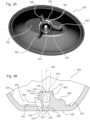
- FIG 2Ashows an exemplary embodiment of an introducer 200 that is configured to be releasably retained inside a retractor 202 such as retractor 100 of Figure 1 .
- the introducer 200comprises a sidewall 204 that extends from a proximal introducer end 206 to a distal introducer end 208.
- proximalrefers to the end that generally faces the surgeon in use
- distalrefers to the end that is located towards or inserted into the patient.
- the proximal introducer end 206may be located at or near a proximal retractor end, and the distal introducer end 208 extends beyond a distal retractor end.
- the retractor 202preferably comprises a hollow tubular retractor passage extending along a longitudinal axis from a proximal retractor end to a distal retractor end, and is dimensioned to allow surgical procedures to be undertaken therethrough.
- the introducer sidewall 204forms an introducer passage 210 that extends along a longitudinal axis 212 extending from the proximal introducer end 206 to the distal introducer end 208.
- a distal tip portion 214 of the introducer 200extends beyond the distal end of the retractor 202.
- the distal tip portion 214 and the retractor 202form a generally smooth and continuous surface for gently displacing brain tissue or the like as the assembly is advanced into the body.
- the distal tip portion 214preferably is tapered with a rounded (such as shown) or conical shape.
- a tip opening 216may be provided at or near the distal introducer end 208, as discussed in more detail below.
- a lock(see, e.g., Figure 1 ) may be provided to selectively hold the introducer 200 to the retractor 202.
- the sidewall 204preferably comprises a continuous wall surface such that the passage 210 has a closed outer perimeter, such as shown in Figure 1 . This can help prevent unwanted entry of body fluids and provide a smooth continuous surface for viewing through the sidewall 204 (if it is transparent) and for guiding instruments down the length of the passage 210 without risk of displacement.
- one or more openings 218may be provided in the sidewall 204 in alternative embodiments.
- the introducer sidewall 204may have any suitable cross-sectional profile (i.e., profile in a plane orthogonal to the longitudinal axis 212).
- the sidewall 204may be circular, elliptical, oval or otherwise generally curved (i.e., comprised entirely of curved surfaces and/or very short straight surfaces that effectively simulate a smoothly-curved shape).
- the cross-sectionmay include one or more rectilinear segments (e.g., a D-shape), or may be entirely rectilinear (e.g., a square or triangular shape).
- the sidewall profilealso may taper to be larger at the proximal end than at the distal end, and preferably reduces at least slightly in size as it approaches the distal introducer end 208.
- the outer surface of the sidewall 204may be shaped to match the shape of a corresponding inner wall of the retractor 202, but this is not strictly required.
- the introducer sidewall 204also preferably has a generally consistent wall thickness along its length, which can facilitate manufacturing and provide a more suitable optical path for viewing through the sidewall 204. It will be understood that cross-sectional shape of the passage 210 will be defined by the shape of the sidewall 204, and therefore the foregoing discussion about the shapes of the sidewall 204 applies also the shape of the passage 210.
- the introducer 200preferably is transparent at least at the distal end 206, and more preferably at the distal tip portion 214, and more preferably along most or the full length of the sidewall 202.
- the transparent portionallows the surgeon to visualize underlying tissue while advancing the introducer 200 through brain tissue or the like, which can provide significant benefits during surgery.
- the introducer 200may be opaque.
- Suitable materials for the introducer 200include polycarbonate and other kinds of plastic, metals such as aluminum, stainless steel or titanium, glass or ceramic, or other materials that are biocompatible or that can be treated via coatings or the like to be biocompatible.
- the passage 210is sized to accommodate a navigation probe 220.
- the probe 220comprises a shaft 222 that extends from a distal probe tip 224 to a proximal probe end 226.
- the probe 220includes a navigation element 228 that is operatively associated with a navigation system to track the position of the probe 220 and convey this information to the surgeon during the course of surgery.
- the navigation element 228may comprise, for example, an optical array (e.g. three or more lights or reflectors in a predetermined physical pattern) that provides a three-dimensional registration of the position of the probe tip 224 when viewed by a corresponding navigation camera system. Such an array may be mounted to the proximal probe end 226 or elsewhere where it can be viewed by the navigation cameras. The need for a line-of-sight between the optical array and the cameras is likely to require the navigation element 228 to be positioned outside the introducer 200.
- the navigation element 228may comprise a magnetic element that can be tracked by a corresponding magnetic tracking system. In this case, it may not be necessary to position the navigation element 228 outside the introducer 200.
- navigation elements 228will be apparent to persons of ordinary skill in the art in view of the present disclosure.
- Examples of navigation probes 220 and corresponding tracking systemsare provided by Stryker Navigation of Kalamazoo, Michigan, U.S.A.; Brainlab AG of Feldmün, Germany; Synaptive Medical of Toronto, Ontario; and Medtronic of Minneapolis, Minnesota, U.S.A.
- the introducer passage 210is significantly larger in the lateral direction (i.e., perpendicular to the longitudinal axis 212) than the probe shaft 222. This may allow the surgeon to visualize down the length of the passage 210 without her vision being unduly obstructed by the probe 220. This also may allow the surgeon to insert other instruments such as an endoscope or aspiration tube into the passage 210 while the probe 220 remains in place, and so on. As a consequence of their disparate relative sizes, the sidewall 204 does not hold the navigation probe shaft 222 against lateral movement within the passage 210.
- the probe tip 224is maintained in registration with the distal introducer end 208 by a probe receptacle 230.
- the probe receptacle 230preferably is located at the geometric center of the introducer profile at the distal introducer end 208 (e.g., the geometric center of the ellipse if the distal introducer end 208 is elliptical), but this is not strictly required in all embodiments.
- the receptacle 230may be offset from the introducer's central axis.
- the probe receptacle 230in this embodiment, comprises a generally circular receptacle wall 232 having an inner surface 236 that extends within the passage 210 from a distal receptacle end 240 to a proximal receptacle end 234.
- the inner surface 236tapers from a relatively large diameter at the proximal receptacle end 234 to a relatively small diameter at a distal receptacle end 240.
- the distal receptacle endmay be located at or near the distal introducer tip 208.
- the receptacle wall 232is sized to restrict the distal probe tip 224 from moving laterally beyond a predefined range of movement.
- the receptacle wall 232may restrict movement of the probe tip 224 to a range of less than 1 millimeter ("mm") in the lateral direction, or more preferably it may be sized to restrict any movement in the lateral direction.
- mmmillimeter
- the diameter of the proximal receptacle end 234may have any size, but preferably is not so large as to significantly obstruct vision through the introducer 200, and not so small that it is overly difficult to position the probe tip 224 within the receptacle 230 during surgery.
- the receptacle wall's tapered surface 236helps guide the probe tip 224 to the proper location within the receptacle 230, and the surface 236 may have a conical or curved profile as viewed from the lateral direction.
- the surface 236also may have a region with a shape specifically selected to match the shape of the probe tip 224. For example, if the probe tip 224 is hemispherical, all or a portion of the surface 236 may have a matching shape.
- a distal portion of the surface 236may have a matching cylindrical shape.
- Other alternativeswill be apparent to persons of ordinary skill in the art in view of the present disclosure.
- the receptacle wall 232also may be shaped and sized to hold the probe tip 224 in close proximity to the distal introducer end 208.
- the distance from the distal introducer end 208 to the probe tip, as measured along the longitudinal axis 212preferably is less than 5.0 mm, and more preferably less than 1.0 mm, and most preferably 0.5 mm or less.
- the probe tip 224is at 1.0 mm or less from the distal introducer end 208 it may not be necessary to attempt to correct for this amount of displacement for purposes of navigating into the brain tissue, as this is expected to be within the normal amount of deviation of brain tissue movement within the skull. It is preferred, but not strictly required, that the probe tip 224 does not protrude beyond the distal introducer end 208.
- the introducer tip opening 216may be located within the probe receptacle 230 at the end of the receptacle wall 232, such as shown in Figure 2B . Alternatively, the introducer tip opening 216 may be located elsewhere in the distal introducer end 208 at a location outside the receptacle 230.
- the probe receptacle 230also may include one or more openings forming flow passages 238 to allow fluid to bypass the receptacle wall 232; this feature can help ensure proper drainage of fluids that might otherwise accumulate at the distal end of the passage 210 at locations between the proximal receptacle end 234 and the sidewall 204.
- a gap 242may be provided between an outer wall 244 of the probe receptacle 230 and the introducer sidewall 204, and fluid may accumulate in this gap 242 under some circumstances.
- the flow passages 238are provided to allow fluid to exit the gap 242.
- the surgeonassembles the introducer 200 and retractor 202 together, places the probe tip 224 into the receptacle 230, and uses computer-aided navigation provided by the probe 220 to guide the assembly to the surgery site.
- the probe 220indicates the position of the distal introducer end 208 relative to the underlying tissue via a computer screen overlay of a representation of the probe and a representation of the tissue.
- the surgeonpreferably can inspect the tissue through transparent walls of the introducer 200 and retractor 202, and can periodically remove the probe 220 as necessary to obtain a better visual image or to perform intermediate procedures such as suctioning fluid and the like.
- Figures 3A and 3Billustrate another embodiment of an introducer 300.
- introducer 300has a probe receptacle 304 that is suspended within the introducer 300 by a number of supports 306.
- the probe receptacle 304may be located on the introducer's centerline, which is parallel to the introducer's longitudinal axis 308, but other locations are possible.
- the probe receptacle 304preferably comprises a receptacle wall 310 (which is circular, but can have other shapes) that extends from a proximal receptacle end 312 to a distal receptacle end 314.
- the receptacle wall 310has an inner surface 316 that tapers from a relatively large size at the proximal receptacle end 312 to a relatively small size at the distal receptacle end 314.
- the inner surface 316is sized and shaped to retain the distal probe tip 224 to prevent the probe tip 224 from moving laterally.
- Figure 3Bshows the probe tip 224 at a position shortly before it fully seats in the probe receptacle 304, to more clearly show that the tapered inner surface 316 transitions from a linearly tapering proximal surface portion 318 to a distal surface portion 320 that is shaped to match the hemispherical shape of the probe tip 224.
- the probe tip 224When fully seated, the probe tip 224 abuts the distal surface portion 320 in something like a ball-and-socket arrangement, with the semi-hemispherical surface of the distal surface portion 320 cupping and closely conforming to the hemispherical probe tip 224.
- the inner surface 316may have other shapes to accommodate different shapes and sizes of probe tip 224. For example, a simple conical shape can accommodate different probes having various tip diameters.
- the supports 306are formed as planar ribs that radiate outward from the introducer's centerline, and extend in parallel with the longitudinal axis 308. In alternative embodiments, the supports 306 may be replaced by other shapes, such as blocks, pillars, and so on.
- the probe receptacle 304may be positioned adjacent to an introducer tip opening 322 that passes through the distal introducer end 302.
- the introducer tip opening 322 and probe receptacle 304are positioned such that fluid located in a gap 328 between the probe receptacle's outer wall 330 and the sidewall 204 can pass through the introducer tip opening 322 without passing through the probe receptacle 304.
- fluidcan flow through the introducer tip opening 322 even when the probe tip 224 is installed within the probe receptacle 304.
- the probe receptacle 304also may include a distal receptacle opening 324 passing thorough the distal receptacle end 314, which provides an additional flow path when the probe is not installed in the probe receptacle 304 and prevents fluid from pooling in the probe receptacle 304.
- the distal receptacle end 314extends into the introducer tip opening 322, such that it lies at or near the plane of the distal introducer end 302.
- the introducer tip opening 322is formed as an annular passage that surrounds the probe receptacle 304, and the supports 306 bridge the gap between the distal introducer end 302 and the probe receptacle 304.
- the supports 306may include arched voids 326 to help reduce any disruption in the flow through the introducer tip opening 322 that the supports 306 might otherwise cause.
- the placement of the distal receptacle end 314 within the introducer tip opening 322can place the probe tip 224 as close as possible to the distal introducer end 302. This simplifies the registration between the probe 220 and the introducer 300 because there is very little offset between their distal ends. However, this arrangement is not required in all embodiments.
- the probe receptacle 304may be moved further in the proximal direction (i.e., back into the introducer passage) to allow more fluid flow capacity through the introducer tip opening 322, to make the introducer tip opening 322 smaller, and for other reasons. If the offset between the probe tip 224 and the distal introducer end 302 is significant, the computer system associated with the probe 220 can be programmed to account for this offset when indicating the position of the introducer 300 to the surgeon, as known in the art.
- the receptacle 304is preferably positioned and sized such that at least a portion of the introducer sidewall 204 at the distal introducer end 302 is visible to the surgeon while the probe tip 224 is installed in the receptacle 304.
- a pair of transparent faces 332 of the sidewall 204may be visible around the receptacle 304 and probe 220. The surgeon can visually inspect the underlying tissue even while the probe 220 is in place, and can move the probe shaft 222 around within the passage 210 to alter her view without displacing the probe tip 224 from the receptacle 304.
- Figures 4A and 4Billustrate another embodiment of an introducer 400. As with Figures 3A and 3B , only the region of the introducer 400 adjacent the distal introducer end 402 is shown. It will be understood that other features of the introducer 400 such as the remainder of the internal passage and other features described previously herein will be connected to the illustrated portion.
- the introducer 400has a probe receptacle 404 that includes a portion that is suspended within the introducer 400 by a number of supports 406.
- the probe receptacle 404may be located on the introducer's centerline, which is parallel to the introducer's longitudinal axis 408, but other locations are possible.
- the probe receptacle 404preferably comprises a receptacle wall 410 (which is circular, but can have other shapes) that extends from a proximal receptacle end 412 to a distal receptacle end 414.
- the receptacle wall 410has an inner surface 416 that tapers from a relatively large size at the proximal receptacle end 412 to a relatively small size at a the distal receptacle end 414.
- the inner surface 416is sized and shaped to retain the distal probe tip 224 to prevent the probe tip 224 from moving laterally when the probe tip 224 is fully seated in the probe receptacle 404.
- the inner surface 416may be similar in construction to the probe receptacle 304 described in relation to Figures 3A and 3B , or have other shapes configured to retain the probe tip 224.
- the inner surface 416may comprise a proximal portion adjacent the proximal receptacle end 412 having a first angle ⁇ 1 relative to the longitudinal axis 408 in the range of 20°-30° (e.g., 25°), an intermediate portion located distally from the upper portion having a second angle ⁇ 2 relative to the longitudinal axis 408 in the range of 5°-15° degrees (e.g., 10°), and a distal portion located distally from the intermediate portion having a hemispherical or semi-hemispherical shape having a radius r in the range of 0.3-0.8 mm.
- This arrangementis expected to provide simple and repeatable installation of the probe tip 224 into the receptacle 404, and provide a distinct feel to indicate when the probe tip 224 is fully seated.
- the probe receptacle 404is positioned adjacent to an introducer tip opening 418 that passes through the distal introducer end 402.
- the introducer tip opening 418 and probe receptacle 404are positioned such that fluid can pass through the introducer tip opening 418 without passing through the proximal receptacle end 412. This allows fluid located in a gap 426 between the probe receptacle's outer wall 428 and the introducer sidewall 204 to flow through the introducer tip opening 418 when the probe tip 224 is installed within the probe receptacle 404.
- the outer wall 428is shown being spaced from the sidewall 204 around its entire perimeter, but it will be appreciated that the outer wall 428 may merge with the sidewall 204 at some locations (such as when the introducer profile is a narrow ellipse or oval, and the receptacle 404 has a circular profile).
- the probe receptacle 404also may include a distal receptacle opening 420 passing thorough the distal receptacle end 414, to provide an additional flow path when the probe is not installed in the probe receptacle 404, and prevent fluid from pooling in the probe receptacle 404.
- the distal receptacle end 414may extend into the introducer tip opening 418, such that it lies at or near the plane of the distal introducer end 402.
- the introducer tip opening 418may be formed as an annular passage that surrounds the probe receptacle 404 with the supports 406 bridging the gap between the distal introducer end 402 and the probe receptacle 404.
- the supports 406may include arched voids to help reduce any disruption in the flow through the introducer tip opening 418 that the supports 406 might otherwise cause.
- locating the distal receptacle end 414 within the introducer tip opening 418can place the probe tip 224 as close as possible to the distal introducer end 402. However, this arrangement is not required in all embodiments.
- the proximal receptacle end 412is larger in the lateral direction (i.e., perpendicular to the longitudinal axis 408) than the introducer tip opening 418.
- Thisprovides a relatively large probe receptacle 404 to help guide the probe 220 into place, while keeping the size of the introducer tip opening 418 relatively small to help prevent the possibility of brain tissue or other delicate tissue being damaged by being forced into or cut by the edges of the introducer tip opening 418.
- Figure 4Bshows how this configuration helps guide the probe tip 224 into the probe receptacle 404, even when it starts at a location that is significantly offset from the probe receptacle's centerline (which, in this example, is collinear with the geometric center of the introducer 400).
- the probe receptacle 404may include one or more (preferably three) openings at a location between the proximal receptacle end 412 and the distal receptacle end 414 to allow fluid to flow to the introducer tip opening 418 without passing through the proximal receptacle end 412.
- openingsmay be, for example, slots 422 extending inward from the outer surface of the probe receptacle 404 to the introducer tip opening 418.
- slots 422allow fluid to drain from the most distal parts of the introducer passage to prevent pooling around the outer perimeter of the probe receptacle 404 at the distal end of the introducer.
- the slots 422 in the shown embodimentextend in the longitudinal direction from the proximal receptacle end 412 to a portion of the sidewall 204 located adjacent the distal receptacle end 414, but other embodiments may have slots having different lengths in the longitudinal direction.
- Each slot 422may terminate at its inner end at an annular passage 424 that overlies the introducer tip opening 418.
- the annular passage 424passes through the inner surface 416 of the receptacle 424 and extends to the introducer tip opening 418, and is expected to help redistribute fluids passing through the introducer tip opening 418 into a more uniform and less restricted flow.
- the supports 406bridge and interrupt the annular passage 424 to join the proximal receptacle end 412 to the distal receptacle end 414 and to suspend the distal receptacle end 414 at the introducer tip opening 418.
- the slots 422 and annular passage 424are sized to prevent the probe tip 224 from entering them (e.g., by having a 0.5 mm maximum width if the smallest probe tip 224 to be used is 0.8 mm or larger).
- the receptacle 404is preferably positioned and sized such that a transparent portion of the introducer sidewall 204 at the distal introducer end 402 is visible to the surgeon while the probe tip 224 is installed in the receptacle 404, to allow visualization of the underlying tissue while the probe 220 is in place.
- Figures 5A through 5Dillustrate another embodiment of an introducer 500, of which only the region of the introducer 500 adjacent the distal introducer end 502 is shown. As with the previous embodiments, it will be understood that other features of the introducer 500 will be connected to the illustrated portion.
- the introducer 500has a probe receptacle 504 having primary supports 506 joining a proximal receptacle end 508 to a distal receptacle end 510.
- the distal receptacle end 510is adjacent (and preferably within) an introducer tip opening 512.
- the proximal receptacle end 508is larger, in a direction perpendicular to the longitudinal axis 514 of the introducer 500, than the introducer tip opening 512.
- this probe receptacle 504is similar to the one illustrated in Figures 4A and 4B , and can include the same variations and features (e.g., a distal receptacle opening, etc.).
- the description of Figures 4A and 4Bapplies equally to the embodiment of Figures 5A-5D .
- Figures 5A-5Ddiffers from Figures 4A and 4B in that secondary supports 516 joining the proximal receptacle end 508 to the distal receptacle end 510 are provided on either side of each slot 518.
- the secondary supports 516preferably have larger voids at their distal ends to provide a more continuous flow passage adjacent the introducer tip opening 512.
- the primary supports 506may be connected to the distal receptacle end 510 by ribs 520 having a lower end located within or near the introducer tip opening 512, while the secondary supports 516 are connected to the distal receptacle end 510 by ribs 522 that are spaced above the introducer tip opening 512, such as best shown in Figure 5C .
- This arrangementprovides additional structures to support the distal receptacle end 510 and to prevent a surgeon from lodging the probe tip 224 in the slots 518 or the gaps between the proximal receptacle end 508 and the distal receptacle end 510, while still providing an annular passage 524 ( Figure 5B ) (which may be interrupted at some locations by the primary support ribs 520) at the introducer tip opening 512 to allow relatively free flow therethrough. Openings 526, located between the secondary supports 516 and primary supports 506, provide flow passages that pass through the inner surface of the probe receptacle 504 and extend along the longitudinal axis 514 to the introducer tip opening 512, to allow vertical fluid flow at various locations.
- fluid located in a gap 528 between the probe receptacle's outer wall 530 and the introducer sidewall 204can flow through the introduced tip opening 512 without having to pass through the proximal introducer end 508, which helps reduce any flow restriction that might be caused by the probe tip 224.
- the primary supports 506may be constructed like the shown secondary supports 516 (i.e., with high arched ribs 522 joining to the distal receptacle end 510). However, the lower ribs of the primary supports 506 such as shown in Figures 5A-5D may be helpful to add strength and to prevent tissue from entering the introducer tip opening 512.
- the secondary supports 516can be structurally identical to the primary supports 506, if it is found that the added support is desirable and the restriction to flow through the introducer tip opening 512 is not unduly compromised. Other alternatives will be apparent to persons of ordinary skill in the art in view of the present disclosure.
- the probe receptacle of any given embodimentmay have any suitable shape to fit any desired navigation probe.
- the probe receptaclemay be configured to fit one particular kind of probe, or it may be configured to retain a number of different navigation probes.
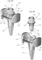
- a probe receptacle as described above with reference to Figures 2A-5Dmay be configured to interchangeably receive any one of four or more different probes such illustrated in Figures 6A to 6D .
- a first probe 600has a tip diameter D of 1.0 mm and a taper angle ⁇ of approximately 6.0°.
- a second probe 602has a tip diameter D of 0.8 mm and a taper angle ⁇ of approximately 7.5°.
- a third probe 604has a tip diameter D of 1.0 mm and a taper angle ⁇ of approximately 18.0°.
- a fourth probe 606has a tip diameter D of 1.0 mm and a 1.0 mm diameter cylindrical shaft 608 extending proximally from the tip. Each of these probes can be inserted with the probe tip seated at the distal end of the receptacle, within 1.0 mm and more preferably within 0.5 mm of the distal introducer end, to hold probe tip against lateral movement.
- the receptaclemay be formed such that it is not likely for the surgeon to "wedge" the probe tip in place, as this may cause difficulty with removing the probe.
- the material of the receptacleis also preferred for the material of the receptacle to be relatively hard to prevent it from deforming to allow the probe tip to become lodged therein. Polycarbonate plastic is expected to be suitable for this purpose, but other materials may be used.
- the receptaclemay be deliberately formed to tend to capture the probe tip in place.
- the probe tipmay include an enlarged end that snaps into a corresponding shape within the receptacle such that a force is required to remove the probe, or the receptacle may include thin deformable ribs that tend to grip the tip of the probe. This may require more care when removing the probe, but add the benefit of not requiring the surgeon to handhold the probe at all times.
- the foregoing embodimentsare expected to help surgeons use introducer and retractor systems with navigation systems. It is expected that surgeons will use the device by assembling the introducer with a retractor, placing the navigation probe in the introducer until the tip of the probe reaches the end of the probe receptacle, and then advancing the three parts forward into the tissue as a unit. During the process, the surgeon can remove the probe to get a better view into the introducer or to insert other instruments or devices into the introducer. If desired, a clamp or other device may be provided to hold the probe in place to free up the surgeon's hands for other tasks. Examples of clamps are disclosed in the aforementioned references, but other mechanisms may be used. Other uses and methods will be apparent to those of ordinary skill in the art in view of this disclosure.
- the introducer tip openingmay add significant benefits to the system, such as by allowing fluids to ventilate to prevent an excessive accumulation of pressure around the introducer, allowing removal of fluids, and if the opening is large enough allowing resection or manual movement of tissue adjacent the opening.
- the tip openingalso may allow air to vent towards the tissue as the introducer is withdrawn from the retractor after the assembly is placed at the surgery site, which can help prevent the introducer from generating suction that pulls on the tissue as the introducer is withdrawn.
- Other benefitswill be apparent in view of the this disclosure and with further use of the system.
- the probe retainer 700comprises a receiver 702 that is affixed to the introducer 200 by a pair of clamps 704.
- the receiver 702includes a channel 706 sized to receive a probe 220.
- the channel 706preferably is a closed passage having a diameter suitable to accommodate a probe 220, but it may include a longitudinal slot or have a "C" or "U” shaped profile, or the like, in other embodiments.
- the channel 706has a proximal channel end 708 facing towards the surgeon, and a distal channel end 710 that extends into the introducer 200. When the probe shaft 222 is located in the channel 706, the channel 706 limits and may completely restrict movement of the probe shaft 222 in the lateral direction.
- the receiver 702may be configured to selectively lock the probe 220 in place within the channel 706.
- the proximal channel end 708may have a threaded outer surface 712 that is configured to engage a corresponding lock nut 714, and one or more cutout sections 716 passing through the proximal channel end 708.
- the threaded outer surface 712 and lock nut 714are configured such that the lock nut 714 compresses the threaded outer surface 712 as it is tightened onto the threaded outer surface 712, such as by providing one or both with a slight taper or making the lock nut's threads slightly smaller in diameter than the threads on the outer threaded surface 712.
- the cutout sections 716provide reliefs to allow the threaded surface 712 to move inwards as the lock nut 714 is tightened.
- the receiver 702also may include one or more retaining lips 720 to prevent the lock nut 714 from being fully removed from the receiver 702.
- lock nut 714may be replaced by a band clamp, a set screw, or other devices.
- Examples of alternative locksare provided in the aforementioned references, and other options will be apparent to the person of ordinary skill in the art in view of this disclosure.
- the receiver 702may include a number of slots 722 (e.g., three slots) that extend proximally from the distal channel end 710.
- the exemplary slots 722extend longitudinally along the longitudinal axis 212 of the assembly, but other orientations may be used (e.g. helical).
- the inner surface of the channel 706is also may be gently tapered such that the diameter of the channel 706 decreases as it approaches the distal channel end 710.
- the final diameter of the channel 706 at the distal channel end 710may be slightly less than the largest diameter probe 220 expected to be used with the device, such that the probe 220 is slightly compressed by the receiver 702 at the distal channel end 710.
- the slots 722allow the channel 706 to flex outwards at the distal channel end 710 to accommodate probes 220 of different sizes. This feature is expected to provide a useful slight retaining force, and may help center the probe 220 within the channel 706.
- the receiveralso may be configured to direct the distal probe tip 224 towards a receptacle (e.g., receptacle 230, 304, 404 or 504) as the probe 220 is installed into the introducer 200.
- a receptaclee.g., receptacle 230, 304, 404 or 504
- the foregoing tapered and slotted arrangementis expected to accomplish this by orienting the channel 706 towards a corresponding receptacle at the distal introducer tip, but other embodiments may use other configurations to do the same thing.
- the channel 706extends in the longitudinal direction, so that it prevents significant angulation of the probe 220 within the channel 706 (i.e., it prevents angulation that could prevent the distal probe tip 224 from entering the receptacle).
- the channel 706may have an inner diameter that is no more than 110% of the largest probe diameter, and a length that is at least 300% and more preferably at least 1000% of the
- the channel 706may comprise a simple ring or passage that is not tapered and does not include slots, or the taper and slots may be replaced by a flexible diaphragm or cantilevered arms that help center the probe 220 within the channel 706.
- the taper and slotsmay be replaced by a flexible diaphragm or cantilevered arms that help center the probe 220 within the channel 706.
- the clamps 704are attached to the receiver 702, and configured to hold the receiver 702 at a fixed location relative to the introducer 200.
- the receiver 702may be centered on the introducer 200, such as shown, or it may be offset from the introducer's centerline.
- the clamps 704are connected to the receiver 702 by clamp arms 724 that are shaped to generally match the shape of the introducer sidewall 204 at the proximal introducer end 206.
- each clamp arm 724has an opening 726 through which the surgeon can view into the introducer passage 210.
- Each clamp 704comprises a tab 728 that is shaped to receive a user's finger, and a hook 730 that is shaped to wrap around a corresponding lip 800 ( Figures 8A-B ) on the introducer.
- the clamp arms 724are located between the tab 728 and the hook 730.
- the clamp arms 724 and hooks 730are movable between a latched position in which the hooks 730 are relatively close to one another, and an unlatched position in which the hooks 730 are relatively far from one another. In their latched position, the hooks 730 are spaced by a first distance at which they wrap around the corresponding lips 800 to secure the probe retainer 700 to the introducer 200.
- the hook spacing in the latched positionmay be slightly greater than their natural resting position when not attached to an introducer 200.
- the clamp arms 724may be under a slight bending force caused by flexing the hooks 730 from their resting position to their latched position. This can help provide a stronger locking connection, and may reduce the likelihood of shifting or moving when connected.
- the clamp arms 724flex and provide a fulcrum about which the hooks 730 rotate until they are located at a second distance from one another. In this position, the hooks 730 release the lips 800 and the probe retainer 70 can be removed from the introducer.
- the clamps 704may be reinstalled onto the introducer 200 by reversing this operation, and the hooks 730 may include ramped surfaces to allow them to be snapped onto the lips 800 simply by pressing the probe retainer 700 against the proximal introducer end 206.
- each clamp arm 724there are two clamp arms 724, each of which has two spaced portions that surround an opening 726 to allow visualization into the introducer 200.
- Each clamp arm 724is connected to the receiver 702 at two locations on opposite sides of the receiver 702.
- the attachments between the receiver 702 and the clamp arms 724may have buttresses 732 to increase the rigidity of the connection. This is expected to help the clamp arms 724 flex in a more predictable manner during the detachment and installation process.
- each clamp arm 724may have a single portion located on one side of the introducer 200, rather than two spaced portions, and the clamps 704 may be turned 90° relative to the shown position such that the grip the introducer 200 from the side rather than from the top.
- Other alternativeswill be apparent to persons of ordinary skill in the art in view of the present disclosure.
- Figures 8A and 8Bshow the embodiment of Figures 7A-B as it appears when installed on an exemplary introducer 200.
- the introducer 200is shown assembled with a corresponding retractor 202.
- the introducer 200preferably includes a probe tip receptacle such as those described previously herein, but it is also envisioned that the probe retainer 700 may be used with introducers that do not have a probe tip receptacle, such as those discussed with reference to Figure 1 .
- the assembly of the probe retainer 700 and navigation probe 220preferably can be removed from or installed into the introducer 200 without separating the introducer 200 from the retractor 202. This provides rapid access to the introducer interior, if necessary.
- Figures 9A and 9Bshow another embodiment of a probe retainer 900.
- the probe retainerincludes a receiver 902 that can be affixed to an by a pair of clamps 904.
- This embodimentis generally the same as the embodiment of Figures 7 through 8B .
- the mechanism for locking the probe shaft in placeis different.
- the receiver channel 906is formed with a threaded proximal end 908, a conically tapered central portion 910, and a relatively narrow distal portion 912.
- the locking nut 914comprises a proximal knob portion 916 that is adapted for use by the surgeon (e.g., knurled, or otherwise shaped to be engaged by fingers or a tool), a male-threaded central portion 918, and a tapered conical distal end 920 having one or more longitudinal slots 922.
- a central passage 924passes through the locking nut 914 to receive the probe shaft.
- the threads 918 of the locking nut 914are configured to thread into the threads 908 of the receiver 902, and the conical distal end 920 of the locking nut 914 is dimensioned to fit into the conical central portion 910 of the receiver 902.
- the locking nut 914is advanced into the receiver 902 by rotating it relative to the receiver 902.
- the locking nut 914When the tapered end 920 of the locking nut 914 engages the tapered central portion 916 of the receiver channel 906, contact between the parts flexes the tapered end 920 radially inwards to compress against the probe shaft.
- the locking nut 914can cooperate with the receiver 902 to engage and hold the probe shaft at a fixed location.
- the locking nut 914may be retained by one or more features that interlock with the receiver 902.
- the receiver 902may have one or more hooks 926 that surround a lip 928 that extends radially from the knob portion 916 of the locking nut 914. These retaining features inhibit the locking nut 914 from accidentally separating from the receiver 902 when the locking nut 914 is fully-loosened.
- the hooks 926may be designed to be deformable to allow the locking nut 914 to be removed.
- Other alternatives and variationswill be apparent to persons of ordinary skill in the art in view of the present disclosure.
- the probe receptacles described hereincan be formed integrally with the introducer by additive manufacturing or molding (the illustrated embodiments show various configurations in which conventional two-part injection molding processes may be used to make the introducer and probe receptacle as a single integrally molded part), or formed separately and attached to the introducer.
- the probe receptaclemay have any sidewall profile shape, rather than the generally circular shapes shown in the embodiments.
- the probe receptaclesalso may have any combination of conical, cylindrical, hemispherical, or other shapes.
- the probe receptaclemay have openings such as the flow passages of Figure 2B and slots of the later embodiments, even when the introducer does not have an introducer tip opening, which can be beneficial to displace fluid from the receptacle to allow free entry of the probe tip.
- openingssuch as the flow passages of Figure 2B and slots of the later embodiments, even when the introducer does not have an introducer tip opening, which can be beneficial to displace fluid from the receptacle to allow free entry of the probe tip.
Landscapes
- Health & Medical Sciences (AREA)
- Surgery (AREA)
- Life Sciences & Earth Sciences (AREA)
- Engineering & Computer Science (AREA)
- Medical Informatics (AREA)
- General Health & Medical Sciences (AREA)
- Biomedical Technology (AREA)
- Heart & Thoracic Surgery (AREA)
- Nuclear Medicine, Radiotherapy & Molecular Imaging (AREA)
- Molecular Biology (AREA)
- Animal Behavior & Ethology (AREA)
- Veterinary Medicine (AREA)
- Public Health (AREA)
- Pathology (AREA)
- Oral & Maxillofacial Surgery (AREA)
- Robotics (AREA)
- Surgical Instruments (AREA)
- Media Introduction/Drainage Providing Device (AREA)
Description
- The present invention relates to delicate tissue surgical retractor systems for use in the brain or other tissue susceptible to retraction injury.
- A variety of different devices have been used to retract delicate tissue during surgical procedures. One such device is illustrated in
United States Patent Publication Number 2010/0010315 .Figure 1 of this publication illustrates a soft tissue retractor system having ahollow retractor 100, and anintroducer 102 that is selectively inserted into theretractor 100. Theretractor 100 and/orintroducer 102 may include ahandle 104 to facilitate manipulation and placement of the retractor system, and a lock to hold the introducer and retractor together. Thehandle 104 is configured to connect to aclamp 106, such as the standardsurgical clamp 106 shown inFigure 1 . The device inFigure 1 (with some modifications) is commercially sold as the "VBAS" device by Vycor Medical, Inc. of Boca Raton, Florida. - A retractor system such as shown in
Figure 1 is often used by inserting theintroducer 102 into theretractor 100 and locking it in place, so the two can be moved and manipulated as a unit. The combined retractor system is inserted into the patient's body and moved to the surgery site, and then theintroducer 102 is unlocked and removed to permit access to the site through theretractor 100. When the unit is in place (either before or after theintroducer 102 is removed), thehandle 104 may be locked to aclamp 106 to hold theretractor 100 in place. Surgeons using this retractor sometimes do not use a clamp to hold the retractor at the surgery site, and often manually manipulate the retractor to access different parts of the surgery site during the surgical procedure. The retractor system and the retractor may be manipulated by holding the proximal ends of the introducer or retractor or by holding the handle. - The device shown in
Figure 1 may have a transparent introducer 102 and/orretractor 100, and surgeons using such devices advantageously use the transparent introducer and retractor to observe the underlying tissue and to visually guide the unit to the surgery site. While it has been found that visual guidance by looking through theintroducer 102 is very beneficial, it also has been found that some form of additional guidance or navigation may be desired in some cases. For example, in some cases, surgeons have used a probe or guide wire (a narrow elongated rod) to guide the movement of the retractor system. In such cases, the probe is advanced to the surgery site, and then the interlocked retractor system is slid over the probe until it reaches the surgery site. This is facilitated by the inclusion of a hole at the tip of the introducer that fits around the probe. If the hole through the tip of the introducer is absent, this method cannot be used. This type of system is described inUnited States Patent Publication Numbers 2008/0109026 and2009/0048622 . These references also show an alternative construction, in which the retractor is not locked to the introducer. - It has been found that some surgeons using the above procedure may use a probe that is integrated into a computer navigation system. For example, the probe may include a so-called "starburst" or the like, on the probe's proximal end (i.e., the end opposite the distal end that is inserted to the surgical site). This and other navigation systems are known in the art. For example, frameless navigation systems and other computerized guidance systems and methods are described in
U.S. Publication No. 2001/0027271 and others, and are commercially available from companies such as Medtronic, Inc., Stryker, BrainLab, AG, and GE Healthcare. As used herein, "computerized guidance" encompasses any method of guiding a device to or at a surgical site that relies on computer visualization and/or control. United States Patent Publication Number 2010/0010315 briefly notes the possibility of using stereotactic guidance or navigation in conjunction with a surgical retractor, but does not illustrate or describe this procedure or any apparatus for accomplishing this objective. Nevertheless, surgeons have been known to use a navigation probe "freehand" with a VBAS device such as shown inFigure 1 . In such cases, the surgeon holds the navigation probe in place within the introducer while advancing the unit towards the surgery site. The tip of the probe may be placed in or near an opening through the tip of the introducer, but the opening through the introducer may be somewhat larger than the probe tip and is oval, and does not hold the probe tip in any particular orientation. Such techniques can suffer from inaccuracy and displacement of the probe from the introducer tip, and it can be difficult to hold the probe in place. Also, in some cases the probe tip may extend partially through the introducer tip opening, which can risk damaging underlying tissue. However, freehand use can be helpful to allow occasional removal of the probe to provide an unobstructed view through the introducer of the underlying tissue.- While computerized surgical guidance systems are well-known, a number of limitations exist with respect to their use with retractor systems, and particularly with systems like those shown in
Figure 1 . For example, while some surgeons use computerized guidance to direct a probe to the surgery site, and then slide the retractor system over the probe to the site, the movement of the retractor may be somewhat imprecise and the process can be unduly cumbersome. This method also is not available if the retractor system does not have a through-hole that fits over the probe (due either to the absence of a hole or a hole that is too small). In addition, the probe does not provide a view of the tissue through which it is advanced, so there is no visual means to perceive and avoid critical tissue (e.g., major blood vessels or nerves) when inserting a probe before inserting a retractor/introducer system. Also, the small-diameter probe may sever delicate tissue cells, such as grey or white brain matter, rather than moving the cells aside and passing between them as would be expected to happen when advancing the retractor system. United States Patent Publication Number 2013/0066154 shows examples of systems for integrating a navigation probe into a surgical introducer. For example,Figures 1-6 of this publication show a navigation probe that is secured to the inside of a pre-existing introducer by resilient means, such as rubber plugs or O-rings. Another embodiment uses a slip fit (e.g.,Figs. 7-8 ), and still another embodiment uses an arm to hold the probe down inside the introducer (Fig. 9 ). Still other versions mount the navigation device outside the introducer, to an arm that is connected to the retractor assembly (Figs. 10-11). While these systems may provide suitable performance, they also have certain potential shortcomings. For example, resilient plugs may slip in the presence of fluids and may be difficulty to disengaged to remove the navigation device during surgery, a slip fit requires careful monitoring to ensure proper positioning, an arm as shown inFigure 9 to hold the probe in place requires the probe to be modified to include a surface against which the arm pushes, and locating the navigation device outside the introducer complicates the correlation between the navigation device and the tip of the introducer or retractor.United States Patent Publication Number 2012/0071748 shows another example of a system for integrating a navigation probe into a surgical introducer. In this case, the probe is retained in a narrow channel through the introducer, and held in place with a threaded locking screw. The locking screw adds an additional potentially-removable part to the operating theater, and therefore this reference adds a separate retaining device (seeFig. 7B ) to prevent the locking screw from being removed. The locking screw also can be relatively difficult to manipulate, particularly when wearing surgical gloves.United States Patent Publication Number 2016/0015374 shows yet another example of a system for integrating a navigation probe into a surgical introducer. The device shown in this publication holds the probe in a tube-like sheath that extends distally into the introducer from the proximal open end of the introducer, and has a convenient single-throw clamp to lock the probe in place. This device also optionally includes a mechanism to indicate when the navigation probe is fully seated in the introducer. While this device is useful to ensure greater accuracy and registration between the introducer and the navigation probe, it may obstruct the surgeon's view to some degree, and may make frequent removal and reinstallation of the navigation probe somewhat cumbersome as compared to freehand use of the probe.- It has been found that there still remains a need to provide alternative apparatus and methods for coordinating the use of guidance systems with surgical introducers.
- Claim 1 defines the invention and dependent claims disclose further embodiments. No surgical methods are claimed. In one exemplary aspect, there is provided an introducer system for use with a navigation probe having a navigation element and a navigation probe shaft having a diameter and terminating at a distal probe tip. The introducer system includes a sidewall extending along a longitudinal axis and forming an introducer passage extending from a proximal introducer end to a distal introducer end, the sidewall being larger, in a lateral direction that is orthogonal to the longitudinal axis, than the navigation probe shaft diameter. The introducer also includes a probe receptacle located at the distal introducer end, the probe receptacle extending along the longitudinal axis within the introducer passage from a proximal receptacle end to a distal receptacle end, the probe receptacle having an inner surface having a first lateral size in the lateral direction at the proximal receptacle end and a second lateral size in the lateral direction at the distal receptacle end, the first lateral size being greater than the second lateral size. The inner surface is configured and dimensioned to receive the distal probe tip and restrict movement of the distal probe tip in the lateral direction, and the sidewall is configured and dimensioned to allow the navigation probe shaft to move in the lateral direction within the passage when the distal probe tip is positioned in the probe receptacle.
- The sidewall may have an elliptical profile in the lateral direction, and the probe receptacle may have a circular profile in the lateral direction. The sidewall may have a profile in the lateral direction, and the probe receptacle may be located at the geometric center of the sidewall profile.
- The inner surface may have a proximal portion adjacent the proximal receptacle end having a first angle relative to the longitudinal axis, and an intermediate portion located distally from the upper portion and having a second angle relative to the longitudinal axis, the second angle being less than the first angle. The first angle may be 20°-30° and the second angle may be 5°-15° degrees. The inner surface further may include a distal portion located distally from the intermediate portion forming at least a portion of a hemispherical surface.
- The probe receptacle may have a distal receptacle opening passing through the distal receptacle end and forming a first fluid flow path between the inner surface and an exterior of the sidewall at the distal introducer end. The introducer also may include an introducer tip opening forming a second fluid flow path between the introducer passage and the exterior of the sidewall at the distal introducer end.
- At least a portion of the probe receptacle may be spaced from the sidewall in the lateral direction by a gap. The probe receptacle may have at least one opening at a location between the receptacle proximal end and the receptacle distal end forming a fluid communication path between the inner surface and the gap.
- The introducer may have an introducer tip opening forming a fluid flow path through the sidewall at the distal introducer end. At least a portion of the probe receptacle may be spaced from the sidewall in the lateral direction by a gap. At least one passage may be provided through an outer wall of the probe receptacle between the receptacle proximal end and the receptacle distal end, the at least one passage forming a fluid communication path between the introducer tip opening and the gap, the fluid communication path being configured to at least partially bypass the proximal receptacle end. The at least one passage may be a plurality of slots extending through the outer wall of the probe receptacle, each of the plurality of slots extending along the longitudinal axis from the proximal receptacle end to a portion of the sidewall located adjacent the distal receptacle end. The introducer may have at least one passage through the inner surface to the introducer tip opening, and the at least one passage may include one or more annular passages.
- The probe receptacle may overlie the introducer tip opening as viewed along the longitudinal axis and the introducer may further include at least one fluid flow path that extends through the introducer tip opening without passing through the proximal receptacle end. The introducer may have one or more supports extending between the sidewall and the probe receptacle to suspend the probe receptacle adjacent the introducer tip opening. The one or more supports may be a plurality of ribs extending along the longitudinal axis. The distal receptacle end may be located within the introducer tip opening. At least part of the one or more supports may be located within the introducer tip opening. The probe receptacle may be smaller or larger in the lateral direction than the introducer tip opening.
- The inner surface may be configured to hold the distal probe tip adjacent the distal introducer end. The inner surface may be configured to hold the distal probe tip within 1.0 mm, or within 0.5 mm, of the distal introducer end. The inner surface may be configured to hold at least four different navigation probes, each navigation probe having a distal probe tip having a geometric shape that is distinct from the other navigation probes, with each of the distal probe tips located, when fully installed in the probe receptacle, within 1.0 mm, or within 0.5 mm, of the distal introducer end.
- At least a portion of the sidewall at the distal introducer end may be transparent and visible from the proximal introducer end when the navigation probe is installed within the introducer.
- The introducer system may also include a probe retainer configured to selectively connect to the proximal introducer end. The probe retainer has a receiver configured to receive the navigation probe shaft when the probe retainer is attached to the proximal introducer end and thereby limit movement of the navigation probe shaft in the lateral direction.
- In another exemplary embodiment, there is provided an introducer system for use with a navigation probe having a navigation element and a navigation probe shaft having a diameter and terminating at a distal probe tip. The introducer system has an introducer having a sidewall extending along a longitudinal axis and forming an introducer passage extending from a proximal introducer end to a distal introducer end, the sidewall being larger, in a lateral direction that is orthogonal to the longitudinal axis, than the navigation probe shaft diameter, and a probe receptacle located at the distal introducer end, the probe receptacle extending along the longitudinal axis within the introducer passage from a proximal receptacle end to a distal receptacle end, the probe receptacle having an inner surface having a first lateral size in the lateral direction at the proximal receptacle end and a second lateral size in the lateral direction at the distal receptacle end, the first lateral size being greater than the second lateral size. The introducer system also includes a probe retainer configured to selectively connect to the proximal introducer end. The probe retainer includes a receiver configured to receive the navigation probe shaft and limit movement of the navigation probe shaft in the lateral direction.
- The probe retainer may have one or more clamps connected to the receiver and configured to selectively connect to the proximal introducer end. The one or more clamps may be two clamps, each clamp being connected to the receiver by a clamp arm having an arm opening therethrough, and each arm opening being aligned with the introducer passage to provide a visual path into the introducer passage. The receiver may have a lock to selectively hold the navigation probe shaft.
- In another exemplary aspect, there is provided an introducer system for use with a navigation probe having a navigation element and a navigation probe shaft having a diameter and terminating at a distal probe tip. The introducer system includes an introducer and a probe retainer. The introducer has a sidewall extending along a longitudinal axis and forming an introducer passage extending from a proximal introducer end to a distal introducer end, the introducer passage being larger, in a lateral direction that is orthogonal to the longitudinal axis, than the navigation probe shaft diameter. The probe retainer is configured to selectively connect to the proximal introducer end. The probe retainer includes a receiver configured to receive the navigation probe shaft and limit movement of the navigation probe shaft in the lateral direction, and a first clamp and a second clamp, the first clamp and the second clamp being connected to the receiver with the receiver located between the first clamp and the second clamp, each of the first clamp and the second clamp being selectively engageable with respective portions of the sidewall to hold the receiver at a fixed location relative to the introducer. The receiver, the first clamp, and the second clamp are configured to provide a visual path through the probe retainer and into the introducer passage.
- Each of the first clamp and the second clamp may be connected to the receiver by a respective clamp arm, each clamp arm having an opening therethrough, the opening being aligned with the introducer passage to form a respective part of the visual path through the probe retainer.
- Each of the first clamp and the second clamp may be connected to the receiver by a respective clamp arm, and may comprise a tab extending from the clamp arm in a first direction, and a hook extending from the clamp arm in a second direction, the second direction being generally opposite the first direction. The first clamp and the second clamp may be connected to the receiver by respective flexible connections, each flexible connection being movable to allow the respective tab to move towards the receiver and the respective hook to move away from the receiver to thereby release the respective hook from engagement with the sidewall. The flexible connections may be bendable clamp arms. The sidewall may have one or more outwardly-extending lips at the proximal introducer end, the one or more outwardly-extending lips having a first portion positioned to be engaged with the respective hook of the first clamp, and a second portion positioned to be engaged with the respective hook of the second clamp.
- The receiver may have a lock to selectively hold the navigation probe shaft against movement along the longitudinal axis. The lock may have a first threaded member having an inner passage with a first tapered surface; and a second threaded member having an outer body having a second tapered surface that fits within the first tapered surface and an inner channel dimensioned to receive the navigation probe shaft; wherein relative rotation between the first threaded member and the second threaded member moves the first tapered surface towards the second tapered surface to compress the inner channel to hold the navigation probe shaft. The second tapered surface may have one or more slots extending along the longitudinal direction.
- The first threaded member may have a hollow passage connected to move with the first clamp and the second clamp, and the second threaded member may have a knob portion connected to the second tapered surface. The probe retainer may have one or more hooks positioned to engage a lip on the second threaded member to inhibit the second threaded member from separating from the first threaded member.
- The second threaded member may be connected to move with the first clamp and the second clamp, and the first threaded member may be a knob portion connected to the first tapered surface. The probe retainer may have one or more hooks positioned to engage a lip on the first threaded member to inhibit the first threaded member from separating from the second threaded member.
- The receiver may have a receiver passage extending along the longitudinal axis from a proximal receiver passage end located in relative proximity to the proximal introducer end, to a distal receiver passage end located in relative proximity to the distal introducer end, and the receiver comprises one or more slots along the longitudinal axis at the distal receiver passage end. An inner diameter of the receiver passage may taper to a smaller size at the distal receiver passage end.
- The introducer may have a probe receptacle located at the distal introducer end, the probe receptacle extending along the longitudinal axis within the introducer passage from a proximal receptacle end to a distal receptacle end, the probe receptacle having an inner surface having a first lateral size in the lateral direction at the proximal receptacle end and a second lateral size in the lateral direction at the distal receptacle end, the first lateral size being greater than the second lateral size. The probe receptacle may have a distal receptacle opening passing through the distal receptacle end and forming a first fluid flow path between the inner surface and an exterior of the sidewall at the distal introducer end. At least a portion of the probe receptacle may be spaced from the sidewall in the lateral direction by a gap. The probe receptacle may have at least one opening at a location between the receptacle proximal end and the receptacle distal end forming a fluid communication path between the inner surface and the gap.
- The introducer may have an introducer tip opening forming a fluid flow path through the sidewall at the distal introducer end.
- The foregoing summary provides a variety of exemplary embodiments that may be used in any suitable combination, and is not intended to impose any limitations upon the invention which is defined by the claims.
- A better understanding of the exemplary embodiments may be understood by reference to the attached drawings, in which like reference numbers designate like parts. The drawings are exemplary, and not intended to limit the claims in any way.
Figure 1 is an example of a prior art delicate tissue retractor system.Figure 2A is a cutaway side view of a first embodiment of an introducer having a guidance probe receptacle.Figure 2B is a cutaway side view of the distal tip of the embodiment ofFigure 2A , shown at a slight oblique angle.Figure 3A illustrates a distal tip of another embodiment of an introducer having a guidance probe receptacle, as viewed from inside the introducer.Figure 3B is a cutaway side view of the distal tip of the embodiment ofFigure 3A .Figure 4A illustrates a distal tip of another embodiment of an introducer having a guidance probe receptacle, as viewed from inside the introducer.Figure 4B is a cutaway side view of the distal tip of the embodiment ofFigure 4A .Figure 5A illustrates a distal tip of another embodiment of an introducer having a guidance probe receptacle, as viewed from inside the introducer.Figure 5B illustrates the embodiment ofFigure 5A , as viewed from outside the introducer.Figure 5C is a cutaway side view of the distal tip of the embodiment ofFigure 5A , as shown alongline 5C-5C.Figure 5D is a cutaway side view of the distal tip of the embodiment ofFigure 5A , as shown alongline 5D-5D.Figures 6A-6D are cross-sectional side views of the distal tips of four different navigation probes.Figures 7A-7B illustrate an embodiment of a centering device in accordance with the invention that may be used with embodiments of introducers.Figures 8A-8B illustrate the embodiment ofFigures 7A-7B in use.Figures 9A and 9B are assembled and exploded views, respectively, of an alternative embodiment of a centering device and probe retainer system in accordance with the invention.- Embodiments may provide various features to supplement or advance the state of the art of surgical introducers and retractor systems. As used herein, the term "guidance system" is intended to include any system for assisting a surgeon with advancing the retractor system to the surgery site, and can include passive systems like guide wires, or active systems like navigation probes that are detected and tracked using a computerized telemetry system. The term "surgeon" includes anyone in the operation theater who might use or manipulate the introducer system. Active probes can be tracked by various techniques, including: optically tracking a "starburst" or other marker mounted on a portion of the probe that remains visible during the procedure; directly monitoring the probe's position using radiation imaging (e.g., X-ray) or magnetic imaging; physically connecting the probe to a frame of reference system to mechanically track the position of the probe; or other means or combinations of means, as known in the art. The terms "navigation" and "guidance" are used interchangeably herein. Embodiments also may be used with manual systems in which the surgeon moves the retractor system entirely by hand, or semi-automated or automated systems that operate under the surgeon's control or automatically advance the retractor system to the surgery site without the surgeon's intervention.
- Embodiments may be used with dedicated systems that are designed anew, or with preexisting systems. For example, embodiments may be used with systems like the one shown in
Figure 1 , such as by supplementing, modifying or replacing theintroducer 102, or with other introducer assemblies, as will be appreciated by persons or ordinary skill in the art. The embodiments described herein may be used with aretractor 100 as shown inFigure 1 , or in other retractors. It will be readily appreciated that the shape of the introducer can be modified to fit into any conventional retractor, and the introducer also may be modified to connect to the retractor (if necessary or desired) using any suitable clamp or other engagement mechanism. For example, embodiments may be used with small-scale versions of introducers like the one shown inFigure 1 , in which the embodiment optionally may be scaled down to allow visibility into the retractor, but providing such visibility is not required in all embodiments. - The exemplary embodiments described herein are directed towards introducers for use in neurosurgery or other operations in and around the brain or skull. However, uses in other parts of the body are also possible.
Figure 2A shows an exemplary embodiment of anintroducer 200 that is configured to be releasably retained inside aretractor 202 such asretractor 100 ofFigure 1 . Theintroducer 200 comprises asidewall 204 that extends from a proximalintroducer end 206 to a distalintroducer end 208. As used herein, "proximal" refers to the end that generally faces the surgeon in use, and "distal" refers to the end that is located towards or inserted into the patient. When connected together, the proximalintroducer end 206 may be located at or near a proximal retractor end, and the distalintroducer end 208 extends beyond a distal retractor end. Theretractor 202 preferably comprises a hollow tubular retractor passage extending along a longitudinal axis from a proximal retractor end to a distal retractor end, and is dimensioned to allow surgical procedures to be undertaken therethrough.- The
introducer sidewall 204 forms anintroducer passage 210 that extends along alongitudinal axis 212 extending from the proximalintroducer end 206 to the distalintroducer end 208. When assembled with theretractor 202, adistal tip portion 214 of theintroducer 200 extends beyond the distal end of theretractor 202. Together, thedistal tip portion 214 and theretractor 202 form a generally smooth and continuous surface for gently displacing brain tissue or the like as the assembly is advanced into the body. Thedistal tip portion 214 preferably is tapered with a rounded (such as shown) or conical shape. Atip opening 216 may be provided at or near the distalintroducer end 208, as discussed in more detail below. A lock (see, e.g.,Figure 1 ) may be provided to selectively hold theintroducer 200 to theretractor 202. - The
sidewall 204 preferably comprises a continuous wall surface such that thepassage 210 has a closed outer perimeter, such as shown inFigure 1 . This can help prevent unwanted entry of body fluids and provide a smooth continuous surface for viewing through the sidewall 204 (if it is transparent) and for guiding instruments down the length of thepassage 210 without risk of displacement. However, one ormore openings 218 may be provided in thesidewall 204 in alternative embodiments. - The
introducer sidewall 204 may have any suitable cross-sectional profile (i.e., profile in a plane orthogonal to the longitudinal axis 212). For example, thesidewall 204 may be circular, elliptical, oval or otherwise generally curved (i.e., comprised entirely of curved surfaces and/or very short straight surfaces that effectively simulate a smoothly-curved shape). If desired, the cross-section may include one or more rectilinear segments (e.g., a D-shape), or may be entirely rectilinear (e.g., a square or triangular shape). The sidewall profile also may taper to be larger at the proximal end than at the distal end, and preferably reduces at least slightly in size as it approaches the distalintroducer end 208. The outer surface of thesidewall 204 may be shaped to match the shape of a corresponding inner wall of theretractor 202, but this is not strictly required. Theintroducer sidewall 204 also preferably has a generally consistent wall thickness along its length, which can facilitate manufacturing and provide a more suitable optical path for viewing through thesidewall 204. It will be understood that cross-sectional shape of thepassage 210 will be defined by the shape of thesidewall 204, and therefore the foregoing discussion about the shapes of thesidewall 204 applies also the shape of thepassage 210. - The
introducer 200 preferably is transparent at least at thedistal end 206, and more preferably at thedistal tip portion 214, and more preferably along most or the full length of thesidewall 202. The transparent portion allows the surgeon to visualize underlying tissue while advancing theintroducer 200 through brain tissue or the like, which can provide significant benefits during surgery. However, in alternative embodiments, theintroducer 200 may be opaque. Suitable materials for theintroducer 200 include polycarbonate and other kinds of plastic, metals such as aluminum, stainless steel or titanium, glass or ceramic, or other materials that are biocompatible or that can be treated via coatings or the like to be biocompatible. - The
passage 210 is sized to accommodate anavigation probe 220. Theprobe 220 comprises ashaft 222 that extends from adistal probe tip 224 to aproximal probe end 226. Theprobe 220 includes anavigation element 228 that is operatively associated with a navigation system to track the position of theprobe 220 and convey this information to the surgeon during the course of surgery. - The
navigation element 228 may comprise, for example, an optical array (e.g. three or more lights or reflectors in a predetermined physical pattern) that provides a three-dimensional registration of the position of theprobe tip 224 when viewed by a corresponding navigation camera system. Such an array may be mounted to theproximal probe end 226 or elsewhere where it can be viewed by the navigation cameras. The need for a line-of-sight between the optical array and the cameras is likely to require thenavigation element 228 to be positioned outside theintroducer 200. Alternatively, thenavigation element 228 may comprise a magnetic element that can be tracked by a corresponding magnetic tracking system. In this case, it may not be necessary to position thenavigation element 228 outside theintroducer 200. Other alternatives ofnavigation elements 228 will be apparent to persons of ordinary skill in the art in view of the present disclosure. Examples of navigation probes 220 and corresponding tracking systems are provided by Stryker Navigation of Kalamazoo, Michigan, U.S.A.; Brainlab AG of Feldkirchen, Germany; Synaptive Medical of Toronto, Ontario; and Medtronic of Minneapolis, Minnesota, U.S.A. - The
introducer passage 210 is significantly larger in the lateral direction (i.e., perpendicular to the longitudinal axis 212) than theprobe shaft 222. This may allow the surgeon to visualize down the length of thepassage 210 without her vision being unduly obstructed by theprobe 220. This also may allow the surgeon to insert other instruments such as an endoscope or aspiration tube into thepassage 210 while theprobe 220 remains in place, and so on. As a consequence of their disparate relative sizes, thesidewall 204 does not hold thenavigation probe shaft 222 against lateral movement within thepassage 210. It expected that some lateral movement of theprobe shaft 222 within thepassage 210 will not critically affect proper navigation, but it is believed to be more important to assure continuous proper registration between thedistal probe tip 224 and a fixed location at the distalintroducer end 208. For example, maintaining theprobe tip 224 with little or no deviation from the geometric center of the introducer profile at the distalintroducer end 208 is expected to provide sufficient registration for accurate navigation, even if the proximal end of theshaft 222 might move laterally within thepassage 210. - In the embodiment of
Figures 2A and 2B , theprobe tip 224 is maintained in registration with the distalintroducer end 208 by aprobe receptacle 230. Theprobe receptacle 230 preferably is located at the geometric center of the introducer profile at the distal introducer end 208 (e.g., the geometric center of the ellipse if the distalintroducer end 208 is elliptical), but this is not strictly required in all embodiments. For example, thereceptacle 230 may be offset from the introducer's central axis. - The
probe receptacle 230, in this embodiment, comprises a generallycircular receptacle wall 232 having aninner surface 236 that extends within thepassage 210 from adistal receptacle end 240 to aproximal receptacle end 234. Theinner surface 236 tapers from a relatively large diameter at theproximal receptacle end 234 to a relatively small diameter at adistal receptacle end 240. The distal receptacle end may be located at or near thedistal introducer tip 208. Thereceptacle wall 232 is sized to restrict thedistal probe tip 224 from moving laterally beyond a predefined range of movement. For example, thereceptacle wall 232 may restrict movement of theprobe tip 224 to a range of less than 1 millimeter ("mm") in the lateral direction, or more preferably it may be sized to restrict any movement in the lateral direction. - The diameter of the
proximal receptacle end 234 may have any size, but preferably is not so large as to significantly obstruct vision through theintroducer 200, and not so small that it is overly difficult to position theprobe tip 224 within thereceptacle 230 during surgery. The receptacle wall's taperedsurface 236 helps guide theprobe tip 224 to the proper location within thereceptacle 230, and thesurface 236 may have a conical or curved profile as viewed from the lateral direction. Thesurface 236 also may have a region with a shape specifically selected to match the shape of theprobe tip 224. For example, if theprobe tip 224 is hemispherical, all or a portion of thesurface 236 may have a matching shape. As another example, if theprobe tip 224 is cylindrical (or has a hemispherical tip with a cylindrical body immediately adjacent the tip), a distal portion of thesurface 236 may have a matching cylindrical shape. Other alternatives will be apparent to persons of ordinary skill in the art in view of the present disclosure. - The
receptacle wall 232 also may be shaped and sized to hold theprobe tip 224 in close proximity to the distalintroducer end 208. For example the distance from the distalintroducer end 208 to the probe tip, as measured along thelongitudinal axis 212, preferably is less than 5.0 mm, and more preferably less than 1.0 mm, and most preferably 0.5 mm or less. Where theprobe tip 224 is at 1.0 mm or less from the distalintroducer end 208 it may not be necessary to attempt to correct for this amount of displacement for purposes of navigating into the brain tissue, as this is expected to be within the normal amount of deviation of brain tissue movement within the skull. It is preferred, but not strictly required, that theprobe tip 224 does not protrude beyond the distalintroducer end 208. - The introducer tip opening 216 (if one is provided) may be located within the
probe receptacle 230 at the end of thereceptacle wall 232, such as shown inFigure 2B . Alternatively, the introducer tip opening 216 may be located elsewhere in the distalintroducer end 208 at a location outside thereceptacle 230. Theprobe receptacle 230 also may include one or more openings formingflow passages 238 to allow fluid to bypass thereceptacle wall 232; this feature can help ensure proper drainage of fluids that might otherwise accumulate at the distal end of thepassage 210 at locations between theproximal receptacle end 234 and thesidewall 204. More specifically, agap 242 may be provided between an outer wall 244 of theprobe receptacle 230 and theintroducer sidewall 204, and fluid may accumulate in thisgap 242 under some circumstances. Theflow passages 238 are provided to allow fluid to exit thegap 242. - In use, the surgeon assembles the
introducer 200 andretractor 202 together, places theprobe tip 224 into thereceptacle 230, and uses computer-aided navigation provided by theprobe 220 to guide the assembly to the surgery site. During navigation, theprobe 220 indicates the position of the distalintroducer end 208 relative to the underlying tissue via a computer screen overlay of a representation of the probe and a representation of the tissue. Throughout the process, the surgeon preferably can inspect the tissue through transparent walls of theintroducer 200 andretractor 202, and can periodically remove theprobe 220 as necessary to obtain a better visual image or to perform intermediate procedures such as suctioning fluid and the like. Figures 3A and 3B illustrate another embodiment of anintroducer 300. For simplicity, only the portion of theintroducer 300 located near the distalintroducer end 302 is shown in these illustrations, and it will be understood that other features of theintroducer 300 such as the remainder of the internal passage and other features described previously herein will be connected to the illustrated portion. In this embodiment,introducer 300 has aprobe receptacle 304 that is suspended within theintroducer 300 by a number ofsupports 306.- The
probe receptacle 304 may be located on the introducer's centerline, which is parallel to the introducer'slongitudinal axis 308, but other locations are possible. Theprobe receptacle 304 preferably comprises a receptacle wall 310 (which is circular, but can have other shapes) that extends from aproximal receptacle end 312 to a distal receptacle end 314. Thereceptacle wall 310 has aninner surface 316 that tapers from a relatively large size at theproximal receptacle end 312 to a relatively small size at the distal receptacle end 314. Theinner surface 316 is sized and shaped to retain thedistal probe tip 224 to prevent theprobe tip 224 from moving laterally. For example,Figure 3B shows theprobe tip 224 at a position shortly before it fully seats in theprobe receptacle 304, to more clearly show that the taperedinner surface 316 transitions from a linearly taperingproximal surface portion 318 to adistal surface portion 320 that is shaped to match the hemispherical shape of theprobe tip 224. When fully seated, theprobe tip 224 abuts thedistal surface portion 320 in something like a ball-and-socket arrangement, with the semi-hemispherical surface of thedistal surface portion 320 cupping and closely conforming to thehemispherical probe tip 224. In other embodiments, theinner surface 316 may have other shapes to accommodate different shapes and sizes ofprobe tip 224. For example, a simple conical shape can accommodate different probes having various tip diameters. - The
supports 306 are formed as planar ribs that radiate outward from the introducer's centerline, and extend in parallel with thelongitudinal axis 308. In alternative embodiments, thesupports 306 may be replaced by other shapes, such as blocks, pillars, and so on. - The
probe receptacle 304 may be positioned adjacent to an introducer tip opening 322 that passes through the distalintroducer end 302. Theintroducer tip opening 322 andprobe receptacle 304 are positioned such that fluid located in agap 328 between the probe receptacle'souter wall 330 and thesidewall 204 can pass through the introducer tip opening 322 without passing through theprobe receptacle 304. Thus, fluid can flow through the introducer tip opening 322 even when theprobe tip 224 is installed within theprobe receptacle 304. Theprobe receptacle 304 also may include adistal receptacle opening 324 passing thorough the distal receptacle end 314, which provides an additional flow path when the probe is not installed in theprobe receptacle 304 and prevents fluid from pooling in theprobe receptacle 304. - In the illustrated embodiment, the distal receptacle end 314 extends into the
introducer tip opening 322, such that it lies at or near the plane of the distalintroducer end 302. Thus, theintroducer tip opening 322 is formed as an annular passage that surrounds theprobe receptacle 304, and thesupports 306 bridge the gap between the distalintroducer end 302 and theprobe receptacle 304. Thesupports 306 may includearched voids 326 to help reduce any disruption in the flow through the introducer tip opening 322 that thesupports 306 might otherwise cause. - The placement of the distal receptacle end 314 within the introducer tip opening 322 can place the
probe tip 224 as close as possible to the distalintroducer end 302. This simplifies the registration between theprobe 220 and theintroducer 300 because there is very little offset between their distal ends. However, this arrangement is not required in all embodiments. For example, theprobe receptacle 304 may be moved further in the proximal direction (i.e., back into the introducer passage) to allow more fluid flow capacity through theintroducer tip opening 322, to make the introducer tip opening 322 smaller, and for other reasons. If the offset between theprobe tip 224 and the distalintroducer end 302 is significant, the computer system associated with theprobe 220 can be programmed to account for this offset when indicating the position of theintroducer 300 to the surgeon, as known in the art. - The
receptacle 304 is preferably positioned and sized such that at least a portion of theintroducer sidewall 204 at the distalintroducer end 302 is visible to the surgeon while theprobe tip 224 is installed in thereceptacle 304. For example, a pair oftransparent faces 332 of the sidewall 204 (which may be flat as shown or curved) may be visible around thereceptacle 304 andprobe 220. The surgeon can visually inspect the underlying tissue even while theprobe 220 is in place, and can move theprobe shaft 222 around within thepassage 210 to alter her view without displacing theprobe tip 224 from thereceptacle 304. Figures 4A and 4B illustrate another embodiment of anintroducer 400. As withFigures 3A and 3B , only the region of theintroducer 400 adjacent the distalintroducer end 402 is shown. It will be understood that other features of theintroducer 400 such as the remainder of the internal passage and other features described previously herein will be connected to the illustrated portion. In this embodiment, theintroducer 400 has aprobe receptacle 404 that includes a portion that is suspended within theintroducer 400 by a number ofsupports 406. Theprobe receptacle 404 may be located on the introducer's centerline, which is parallel to the introducer'slongitudinal axis 408, but other locations are possible.- The
probe receptacle 404 preferably comprises a receptacle wall 410 (which is circular, but can have other shapes) that extends from aproximal receptacle end 412 to adistal receptacle end 414. Thereceptacle wall 410 has aninner surface 416 that tapers from a relatively large size at theproximal receptacle end 412 to a relatively small size at a thedistal receptacle end 414. Theinner surface 416 is sized and shaped to retain thedistal probe tip 224 to prevent theprobe tip 224 from moving laterally when theprobe tip 224 is fully seated in theprobe receptacle 404. Theinner surface 416 may be similar in construction to theprobe receptacle 304 described in relation toFigures 3A and 3B , or have other shapes configured to retain theprobe tip 224. For example, theinner surface 416 may comprise a proximal portion adjacent theproximal receptacle end 412 having a first angle θ1 relative to thelongitudinal axis 408 in the range of 20°-30° (e.g., 25°), an intermediate portion located distally from the upper portion having a second angle θ2 relative to thelongitudinal axis 408 in the range of 5°-15° degrees (e.g., 10°), and a distal portion located distally from the intermediate portion having a hemispherical or semi-hemispherical shape having a radius r in the range of 0.3-0.8 mm. This arrangement is expected to provide simple and repeatable installation of theprobe tip 224 into thereceptacle 404, and provide a distinct feel to indicate when theprobe tip 224 is fully seated. - The
probe receptacle 404 is positioned adjacent to an introducer tip opening 418 that passes through the distalintroducer end 402. Theintroducer tip opening 418 andprobe receptacle 404 are positioned such that fluid can pass through the introducer tip opening 418 without passing through theproximal receptacle end 412. This allows fluid located in agap 426 between the probe receptacle'souter wall 428 and theintroducer sidewall 204 to flow through theintroducer tip opening 418 when theprobe tip 224 is installed within theprobe receptacle 404. In the shown embodiment, theouter wall 428 is shown being spaced from thesidewall 204 around its entire perimeter, but it will be appreciated that theouter wall 428 may merge with thesidewall 204 at some locations (such as when the introducer profile is a narrow ellipse or oval, and thereceptacle 404 has a circular profile). - The
probe receptacle 404 also may include adistal receptacle opening 420 passing thorough thedistal receptacle end 414, to provide an additional flow path when the probe is not installed in theprobe receptacle 404, and prevent fluid from pooling in theprobe receptacle 404. Thedistal receptacle end 414 may extend into theintroducer tip opening 418, such that it lies at or near the plane of the distalintroducer end 402. In this case, the introducer tip opening 418 may be formed as an annular passage that surrounds theprobe receptacle 404 with thesupports 406 bridging the gap between the distalintroducer end 402 and theprobe receptacle 404. Thesupports 406 may include arched voids to help reduce any disruption in the flow through the introducer tip opening 418 that thesupports 406 might otherwise cause. As with the embodiment ofFigures 3A and 3B , locating thedistal receptacle end 414 within the introducer tip opening 418 can place theprobe tip 224 as close as possible to the distalintroducer end 402. However, this arrangement is not required in all embodiments. - In this embodiment, the
proximal receptacle end 412 is larger in the lateral direction (i.e., perpendicular to the longitudinal axis 408) than theintroducer tip opening 418. This provides a relativelylarge probe receptacle 404 to help guide theprobe 220 into place, while keeping the size of the introducer tip opening 418 relatively small to help prevent the possibility of brain tissue or other delicate tissue being damaged by being forced into or cut by the edges of theintroducer tip opening 418.Figure 4B shows how this configuration helps guide theprobe tip 224 into theprobe receptacle 404, even when it starts at a location that is significantly offset from the probe receptacle's centerline (which, in this example, is collinear with the geometric center of the introducer 400). - Where the
proximal receptacle end 412 is larger than theintroducer tip opening 418, it may be particularly favorable to provide additional provisions for assuring suitable flow through theintroducer tip opening 418. To this end, theprobe receptacle 404 may include one or more (preferably three) openings at a location between theproximal receptacle end 412 and thedistal receptacle end 414 to allow fluid to flow to the introducer tip opening 418 without passing through theproximal receptacle end 412. Such openings may be, for example,slots 422 extending inward from the outer surface of theprobe receptacle 404 to theintroducer tip opening 418. Theseslots 422 allow fluid to drain from the most distal parts of the introducer passage to prevent pooling around the outer perimeter of theprobe receptacle 404 at the distal end of the introducer. Theslots 422 in the shown embodiment extend in the longitudinal direction from theproximal receptacle end 412 to a portion of thesidewall 204 located adjacent thedistal receptacle end 414, but other embodiments may have slots having different lengths in the longitudinal direction. - Each
slot 422 may terminate at its inner end at anannular passage 424 that overlies theintroducer tip opening 418. Theannular passage 424 passes through theinner surface 416 of thereceptacle 424 and extends to theintroducer tip opening 418, and is expected to help redistribute fluids passing through the introducer tip opening 418 into a more uniform and less restricted flow. Thesupports 406 bridge and interrupt theannular passage 424 to join theproximal receptacle end 412 to thedistal receptacle end 414 and to suspend thedistal receptacle end 414 at theintroducer tip opening 418. Theslots 422 andannular passage 424 are sized to prevent theprobe tip 224 from entering them (e.g., by having a 0.5 mm maximum width if thesmallest probe tip 224 to be used is 0.8 mm or larger). - As with the other embodiments, the
receptacle 404 is preferably positioned and sized such that a transparent portion of theintroducer sidewall 204 at the distalintroducer end 402 is visible to the surgeon while theprobe tip 224 is installed in thereceptacle 404, to allow visualization of the underlying tissue while theprobe 220 is in place. Figures 5A through 5D illustrate another embodiment of anintroducer 500, of which only the region of theintroducer 500 adjacent the distalintroducer end 502 is shown. As with the previous embodiments, it will be understood that other features of theintroducer 500 will be connected to the illustrated portion. In this embodiment, theintroducer 500 has aprobe receptacle 504 havingprimary supports 506 joining aproximal receptacle end 508 to adistal receptacle end 510. Thedistal receptacle end 510 is adjacent (and preferably within) anintroducer tip opening 512. Theproximal receptacle end 508 is larger, in a direction perpendicular to thelongitudinal axis 514 of theintroducer 500, than theintroducer tip opening 512. The structure of thisprobe receptacle 504 is similar to the one illustrated inFigures 4A and 4B , and can include the same variations and features (e.g., a distal receptacle opening, etc.). The description ofFigures 4A and 4B applies equally to the embodiment ofFigures 5A-5D .- The embodiment of
Figures 5A-5D differs fromFigures 4A and 4B in thatsecondary supports 516 joining theproximal receptacle end 508 to thedistal receptacle end 510 are provided on either side of eachslot 518. Thesecondary supports 516 preferably have larger voids at their distal ends to provide a more continuous flow passage adjacent theintroducer tip opening 512. For example, the primary supports 506 may be connected to thedistal receptacle end 510 byribs 520 having a lower end located within or near theintroducer tip opening 512, while thesecondary supports 516 are connected to thedistal receptacle end 510 byribs 522 that are spaced above theintroducer tip opening 512, such as best shown inFigure 5C . This arrangement provides additional structures to support thedistal receptacle end 510 and to prevent a surgeon from lodging theprobe tip 224 in theslots 518 or the gaps between theproximal receptacle end 508 and thedistal receptacle end 510, while still providing an annular passage 524 (Figure 5B ) (which may be interrupted at some locations by the primary support ribs 520) at the introducer tip opening 512 to allow relatively free flow therethrough.Openings 526, located between thesecondary supports 516 andprimary supports 506, provide flow passages that pass through the inner surface of theprobe receptacle 504 and extend along thelongitudinal axis 514 to theintroducer tip opening 512, to allow vertical fluid flow at various locations. As with the previous embodiments, fluid located in agap 528 between the probe receptacle'souter wall 530 and theintroducer sidewall 204 can flow through the introducedtip opening 512 without having to pass through the proximalintroducer end 508, which helps reduce any flow restriction that might be caused by theprobe tip 224. - It is also contemplated that the primary supports 506 may be constructed like the shown secondary supports 516 (i.e., with high
arched ribs 522 joining to the distal receptacle end 510). However, the lower ribs of theprimary supports 506 such as shown inFigures 5A-5D may be helpful to add strength and to prevent tissue from entering theintroducer tip opening 512. Alternatively, thesecondary supports 516 can be structurally identical to the primary supports 506, if it is found that the added support is desirable and the restriction to flow through theintroducer tip opening 512 is not unduly compromised. Other alternatives will be apparent to persons of ordinary skill in the art in view of the present disclosure. - The probe receptacle of any given embodiment may have any suitable shape to fit any desired navigation probe. The probe receptacle may be configured to fit one particular kind of probe, or it may be configured to retain a number of different navigation probes. For example, a probe receptacle as described above with reference to
Figures 2A-5D may be configured to interchangeably receive any one of four or more different probes such illustrated inFigures 6A to 6D . Afirst probe 600 has a tip diameter D of 1.0 mm and a taper angle θ of approximately 6.0°. Asecond probe 602 has a tip diameter D of 0.8 mm and a taper angle θ of approximately 7.5°. Athird probe 604 has a tip diameter D of 1.0 mm and a taper angle θ of approximately 18.0°. Afourth probe 606 has a tip diameter D of 1.0 mm and a 1.0 mm diametercylindrical shaft 608 extending proximally from the tip. Each of these probes can be inserted with the probe tip seated at the distal end of the receptacle, within 1.0 mm and more preferably within 0.5 mm of the distal introducer end, to hold probe tip against lateral movement. - The receptacle may be formed such that it is not likely for the surgeon to "wedge" the probe tip in place, as this may cause difficulty with removing the probe. To this end, it is preferred for the taper angle of the receptacle's inner wall to not exactly match the taper angle of any particular probe tip in such a way to lock the two parts together. It is also preferred for the material of the receptacle to be relatively hard to prevent it from deforming to allow the probe tip to become lodged therein. Polycarbonate plastic is expected to be suitable for this purpose, but other materials may be used. Of course, a surgeon applying a very large force on the probe might lodge it in the receptacle regardless of how the receptacle is designed, so it will be understood that these preferences are predicated on normal use of the instrument and are not intended to set strict requirements for all embodiments under all circumstances.
- Alternatively, the receptacle may be deliberately formed to tend to capture the probe tip in place. For example, the probe tip may include an enlarged end that snaps into a corresponding shape within the receptacle such that a force is required to remove the probe, or the receptacle may include thin deformable ribs that tend to grip the tip of the probe. This may require more care when removing the probe, but add the benefit of not requiring the surgeon to handhold the probe at all times.
- The foregoing embodiments are expected to help surgeons use introducer and retractor systems with navigation systems. It is expected that surgeons will use the device by assembling the introducer with a retractor, placing the navigation probe in the introducer until the tip of the probe reaches the end of the probe receptacle, and then advancing the three parts forward into the tissue as a unit. During the process, the surgeon can remove the probe to get a better view into the introducer or to insert other instruments or devices into the introducer. If desired, a clamp or other device may be provided to hold the probe in place to free up the surgeon's hands for other tasks. Examples of clamps are disclosed in the aforementioned references, but other mechanisms may be used. Other uses and methods will be apparent to those of ordinary skill in the art in view of this disclosure.
- The introducer tip opening may add significant benefits to the system, such as by allowing fluids to ventilate to prevent an excessive accumulation of pressure around the introducer, allowing removal of fluids, and if the opening is large enough allowing resection or manual movement of tissue adjacent the opening. The tip opening also may allow air to vent towards the tissue as the introducer is withdrawn from the retractor after the assembly is placed at the surgery site, which can help prevent the introducer from generating suction that pulls on the tissue as the introducer is withdrawn. Other benefits will be apparent in view of the this disclosure and with further use of the system.
- While it is expected that the foregoing embodiments can be used "freehand" by simply placing the
probe tip 224 into the probe receptacle, in some cases a surgeon may wish to lock theprobe 220 in place within theintroducer 200. This may be accomplished by using a retaining mechanism, such as theexemplary probe retainer 700 shown inFigures 7A-8B . - The
probe retainer 700 comprises areceiver 702 that is affixed to theintroducer 200 by a pair ofclamps 704. Thereceiver 702 includes achannel 706 sized to receive aprobe 220. Thechannel 706 preferably is a closed passage having a diameter suitable to accommodate aprobe 220, but it may include a longitudinal slot or have a "C" or "U" shaped profile, or the like, in other embodiments. Thechannel 706 has aproximal channel end 708 facing towards the surgeon, and adistal channel end 710 that extends into theintroducer 200. When theprobe shaft 222 is located in thechannel 706, thechannel 706 limits and may completely restrict movement of theprobe shaft 222 in the lateral direction. - The
receiver 702 may be configured to selectively lock theprobe 220 in place within thechannel 706. For example, theproximal channel end 708 may have a threadedouter surface 712 that is configured to engage acorresponding lock nut 714, and one ormore cutout sections 716 passing through theproximal channel end 708. The threadedouter surface 712 and locknut 714 are configured such that thelock nut 714 compresses the threadedouter surface 712 as it is tightened onto the threadedouter surface 712, such as by providing one or both with a slight taper or making the lock nut's threads slightly smaller in diameter than the threads on the outer threadedsurface 712. Thecutout sections 716 provide reliefs to allow the threadedsurface 712 to move inwards as thelock nut 714 is tightened. Thus, as thelock nut 714 is tightened on the threadedouter surface 712, the threadedouter surface 712 moves radially inwards, and aninner surface 718 of theproximal channel end 708 clamps against and secures theprobe 220 in place. Thereceiver 702 also may include one or more retaininglips 720 to prevent thelock nut 714 from being fully removed from thereceiver 702. - Other locking mechanisms may be used in other embodiments. For example, the
lock nut 714 may be replaced by a band clamp, a set screw, or other devices. Examples of alternative locks are provided in the aforementioned references, and other options will be apparent to the person of ordinary skill in the art in view of this disclosure. - In the shown embodiment, the
receiver 702 may include a number of slots 722 (e.g., three slots) that extend proximally from thedistal channel end 710. Theexemplary slots 722 extend longitudinally along thelongitudinal axis 212 of the assembly, but other orientations may be used (e.g. helical). The inner surface of thechannel 706 is also may be gently tapered such that the diameter of thechannel 706 decreases as it approaches thedistal channel end 710. The final diameter of thechannel 706 at thedistal channel end 710 may be slightly less than thelargest diameter probe 220 expected to be used with the device, such that theprobe 220 is slightly compressed by thereceiver 702 at thedistal channel end 710. Theslots 722 allow thechannel 706 to flex outwards at thedistal channel end 710 to accommodateprobes 220 of different sizes. This feature is expected to provide a useful slight retaining force, and may help center theprobe 220 within thechannel 706. - The receiver also may be configured to direct the
distal probe tip 224 towards a receptacle (e.g.,receptacle probe 220 is installed into theintroducer 200. The foregoing tapered and slotted arrangement is expected to accomplish this by orienting thechannel 706 towards a corresponding receptacle at the distal introducer tip, but other embodiments may use other configurations to do the same thing. Preferably, thechannel 706 extends in the longitudinal direction, so that it prevents significant angulation of theprobe 220 within the channel 706 (i.e., it prevents angulation that could prevent thedistal probe tip 224 from entering the receptacle). For example, thechannel 706 may have an inner diameter that is no more than 110% of the largest probe diameter, and a length that is at least 300% and more preferably at least 1000% of the largest probe diameter. - Despite the foregoing, in other embodiments the
channel 706 may comprise a simple ring or passage that is not tapered and does not include slots, or the taper and slots may be replaced by a flexible diaphragm or cantilevered arms that help center theprobe 220 within thechannel 706. Other alternatives will be apparent to persons of ordinary skill in the art in view of the present disclosure. - The
clamps 704 are attached to thereceiver 702, and configured to hold thereceiver 702 at a fixed location relative to theintroducer 200. Thereceiver 702 may be centered on theintroducer 200, such as shown, or it may be offset from the introducer's centerline. In this embodiment, theclamps 704 are connected to thereceiver 702 byclamp arms 724 that are shaped to generally match the shape of theintroducer sidewall 204 at the proximalintroducer end 206. Thus, eachclamp arm 724 has anopening 726 through which the surgeon can view into theintroducer passage 210. - Each
clamp 704 comprises atab 728 that is shaped to receive a user's finger, and ahook 730 that is shaped to wrap around a corresponding lip 800 (Figures 8A-B ) on the introducer. Theclamp arms 724 are located between thetab 728 and thehook 730. Theclamp arms 724 and hooks 730 are movable between a latched position in which thehooks 730 are relatively close to one another, and an unlatched position in which thehooks 730 are relatively far from one another. In their latched position, thehooks 730 are spaced by a first distance at which they wrap around the correspondinglips 800 to secure theprobe retainer 700 to theintroducer 200. The hook spacing in the latched position may be slightly greater than their natural resting position when not attached to anintroducer 200. Thus, when attached to theintroducer 200, theclamp arms 724 may be under a slight bending force caused by flexing thehooks 730 from their resting position to their latched position. This can help provide a stronger locking connection, and may reduce the likelihood of shifting or moving when connected. - When the surgeon pinches the
tabs 728 together, theclamp arms 724 flex and provide a fulcrum about which thehooks 730 rotate until they are located at a second distance from one another. In this position, thehooks 730 release thelips 800 and the probe retainer 70 can be removed from the introducer. Theclamps 704 may be reinstalled onto theintroducer 200 by reversing this operation, and thehooks 730 may include ramped surfaces to allow them to be snapped onto thelips 800 simply by pressing theprobe retainer 700 against the proximalintroducer end 206. - In the exemplary embodiment, there are two
clamp arms 724, each of which has two spaced portions that surround anopening 726 to allow visualization into theintroducer 200. Eachclamp arm 724 is connected to thereceiver 702 at two locations on opposite sides of thereceiver 702. The attachments between thereceiver 702 and theclamp arms 724 may havebuttresses 732 to increase the rigidity of the connection. This is expected to help the clamparms 724 flex in a more predictable manner during the detachment and installation process. - The foregoing
clamp 704 arrangement is expected to provide simple and reliable engagement to selectively connect theprobe retainer 700 to theintroducer 200. However, other embodiments may use different structures to hold the probe in place. For example, theflexible clamp arms 724 may be replaced by more rigid members having a mechanical pivot such as a pivot pin or the like and a return spring to bias thehooks 730 to the clamped position. As another example, eachclamp arm 724 may have a single portion located on one side of theintroducer 200, rather than two spaced portions, and theclamps 704 may be turned 90° relative to the shown position such that the grip theintroducer 200 from the side rather than from the top. Other alternatives will be apparent to persons of ordinary skill in the art in view of the present disclosure. Figures 8A and 8B show the embodiment ofFigures 7A-B as it appears when installed on anexemplary introducer 200. Theintroducer 200 is shown assembled with acorresponding retractor 202. Theintroducer 200 preferably includes a probe tip receptacle such as those described previously herein, but it is also envisioned that theprobe retainer 700 may be used with introducers that do not have a probe tip receptacle, such as those discussed with reference toFigure 1 . The assembly of theprobe retainer 700 andnavigation probe 220 preferably can be removed from or installed into theintroducer 200 without separating theintroducer 200 from theretractor 202. This provides rapid access to the introducer interior, if necessary.Figures 9A and 9B show another embodiment of aprobe retainer 900. In this case, the probe retainer includes areceiver 902 that can be affixed to an by a pair ofclamps 904. This embodiment is generally the same as the embodiment ofFigures 7 through 8B . However, in this embodiment the mechanism for locking the probe shaft in place is different. Thereceiver channel 906 is formed with a threadedproximal end 908, a conically taperedcentral portion 910, and a relatively narrowdistal portion 912. The lockingnut 914 comprises aproximal knob portion 916 that is adapted for use by the surgeon (e.g., knurled, or otherwise shaped to be engaged by fingers or a tool), a male-threadedcentral portion 918, and a tapered conicaldistal end 920 having one or morelongitudinal slots 922. Acentral passage 924 passes through the lockingnut 914 to receive the probe shaft. Thethreads 918 of the lockingnut 914 are configured to thread into thethreads 908 of thereceiver 902, and the conicaldistal end 920 of the lockingnut 914 is dimensioned to fit into the conicalcentral portion 910 of thereceiver 902. The lockingnut 914 is advanced into thereceiver 902 by rotating it relative to thereceiver 902. When thetapered end 920 of the lockingnut 914 engages the taperedcentral portion 916 of thereceiver channel 906, contact between the parts flexes thetapered end 920 radially inwards to compress against the probe shaft. Thus, the lockingnut 914 can cooperate with thereceiver 902 to engage and hold the probe shaft at a fixed location.- The locking
nut 914 may be retained by one or more features that interlock with thereceiver 902. For example, thereceiver 902 may have one ormore hooks 926 that surround alip 928 that extends radially from theknob portion 916 of the lockingnut 914. These retaining features inhibit the lockingnut 914 from accidentally separating from thereceiver 902 when the lockingnut 914 is fully-loosened. However, in some embodiments, thehooks 926 may be designed to be deformable to allow the lockingnut 914 to be removed. Other alternatives and variations will be apparent to persons of ordinary skill in the art in view of the present disclosure. - It will be appreciated that the foregoing embodiments may be modified in various ways. As one example, features disclosed in one embodiment may be used with any of the other embodiments. As another example, the probe receptacles described herein can be formed integrally with the introducer by additive manufacturing or molding (the illustrated embodiments show various configurations in which conventional two-part injection molding processes may be used to make the introducer and probe receptacle as a single integrally molded part), or formed separately and attached to the introducer. As another example, the probe receptacle may have any sidewall profile shape, rather than the generally circular shapes shown in the embodiments. The probe receptacles also may have any combination of conical, cylindrical, hemispherical, or other shapes. It is also envisioned that the probe receptacle may have openings such as the flow passages of
Figure 2B and slots of the later embodiments, even when the introducer does not have an introducer tip opening, which can be beneficial to displace fluid from the receptacle to allow free entry of the probe tip. Other alternatives will be apparent to persons of ordinary skill in the art in view of the present disclosure. - The present disclosure describes a number of new, useful and nonobvious features and/or combinations of features that may be used alone or together. The embodiments described herein are all exemplary, and are not intended to limit the scope of the disclosure. It will be appreciated that the embodiments described herein can be modified and adapted in various and equivalent ways, and all such modifications and adaptations are intended to be included in the scope of this disclosure. The scope of the invention is defined by the claims.
Claims (15)
- A surgical navigation probe assembly (700, 900) comprising:a receiver (702, 902) having:a receiver channel (706, 906) extending in a longitudinal direction and configured to receive a navigation probe shaft in a proximal open end of the receiver channel, and limit movement of the navigation probe shaft in a lateral direction that is perpendicular to the longitudinal direction, anda first threaded surface (712, 908); anda lock (714, 914) having:a central passage (924) extending in the longitudinal direction, anda second threaded surface (918);wherein the lock and receiver are movable between a first configuration in which the lock and receiver allow the navigation probe shaft to move relative to the lock and receiver along the longitudinal direction, and a second configuration in which the lock and receiver prevent the navigation probe from moving relative to the lock and receiver along the longitudinal direction; and,wherein the lock is rotatable relative to the receiver to engage the first threaded surface with the second threaded surface to thereby move the lock and receiver between the first configuration and the second configuration.
- The surgical navigation probe assembly of claim 1, wherein:the receiver channel comprises:a first inner surface portion (908) extending from the proximal open end (708), wherein the first threaded surface is located in the first inner surface portion, anda second inner surface portion (910) extending from the first inner surface portion; andthe lock comprises:a first outer surface portion (918) surrounding the central passage, wherein the second threaded surface is located on the first outer surface portion, anda second outer surface portion (920) extending from the first outer surface portion;wherein the second inner surface portion is configured to compress the second outer surface portion against the navigation probe shaft when the lock and receiver are in the second configuration.
- The surgical navigation probe assembly of claim 2, wherein at least one of the second inner surface portion and the second outer surface portion comprise a taper facing the other of the second inner surface portion and the second outer surface portion.
- The surgical navigation probe assembly of claim 2 or 3, wherein the lock further comprises one or more slots (922) extending in the longitudinal direction and into the second outer surface portion.
- The surgical navigation probe assembly of any of claims 2-4, wherein the lock comprises a knob portion, wherein the first outer surface portion is located between the knob portion and the second outer surface portion.
- The surgical navigation probe assembly of any of claims 2-5, wherein the receiver further comprises a hook (926) configured to contact the lock when the lock and receiver are in the second configuration, to thereby prevent the lock from separating from the receiver.
- The surgical navigation probe assembly of claim 1, wherein the first threaded surface is formed on an outer surface of the receiver, and the second threaded surface is formed on an inner surface of the lock configured to surround the outer surface of the receiver.
- The surgical navigation probe assembly of claim 7, wherein the receiver channel comprises one or more slots (716) extending along the longitudinal direction from the proximal open end of the receiver channel.
- The surgical navigation probe assembly of claim 8, wherein the one or more slots intersect the first threaded surface.
- The surgical navigation probe assembly of any of claims 7-9, wherein:at least one of the receiver and the lock comprises a tapered surface; andthe tapered surface is configured to compress an inner surface of the receiver channel against the navigation probe shaft when the lock is in the second configuration.
- The surgical navigation probe assembly of any of claims 7-10, wherein the receiver comprises a lip (720) configured to contact the lock when the lock and receiver are in the second configuration, to thereby prevent the lock from separating from the receiver.
- The surgical navigation probe assembly of claim 1, wherein the receiver channel extends from the proximal open end to a distal open end (710) and one or more slots (722) extend along the longitudinal direction from the distal open end.
- The surgical navigation probe assembly of claim 1, wherein the receiver comprises at least one hook (926) or lip (720) positioned to contact a corresponding surface of the lock when the lock and the receiver are in the second configuration, to thereby prevent the lock from separating from the receiver.
- The surgical navigation probe assembly of any of the preceding claims, further comprising an introducer (200) extending from the receiver along the longitudinal direction to a tapered distal introducer end.
- The surgical navigation probe assembly of claim 14, further comprising a hollow retractor (202) configured to selective secure to surround the introducer, with the tapered distal introducer end protruding from the retractor.
Applications Claiming Priority (4)
| Application Number | Priority Date | Filing Date | Title |
|---|---|---|---|
| US201662418507P | 2016-11-07 | 2016-11-07 | |
| US15/372,890US10376258B2 (en) | 2016-11-07 | 2016-12-08 | Surgical introducer with guidance system receptacle |
| PCT/US2017/060373WO2018085827A1 (en) | 2016-11-07 | 2017-11-07 | Surgical introducer with guidance system receptacle |
| EP17868180.5AEP3534802B1 (en) | 2016-11-07 | 2017-11-07 | Surgical introducer with guidance system receptacle |
Related Parent Applications (1)
| Application Number | Title | Priority Date | Filing Date |
|---|---|---|---|
| EP17868180.5ADivisionEP3534802B1 (en) | 2016-11-07 | 2017-11-07 | Surgical introducer with guidance system receptacle |
Publications (2)
| Publication Number | Publication Date |
|---|---|
| EP4218610A1 EP4218610A1 (en) | 2023-08-02 |
| EP4218610B1true EP4218610B1 (en) | 2024-10-09 |
Family
ID=62065231
Family Applications (2)
| Application Number | Title | Priority Date | Filing Date |
|---|---|---|---|
| EP17868180.5AActiveEP3534802B1 (en) | 2016-11-07 | 2017-11-07 | Surgical introducer with guidance system receptacle |
| EP23165657.0AActiveEP4218610B1 (en) | 2016-11-07 | 2017-11-07 | Surgical introducer with guidance system receptacle |
Family Applications Before (1)
| Application Number | Title | Priority Date | Filing Date |
|---|---|---|---|
| EP17868180.5AActiveEP3534802B1 (en) | 2016-11-07 | 2017-11-07 | Surgical introducer with guidance system receptacle |
Country Status (6)
| Country | Link |
|---|---|
| US (2) | US10376258B2 (en) |
| EP (2) | EP3534802B1 (en) |
| JP (3) | JP7021238B2 (en) |
| CN (2) | CN110267602B (en) |
| CA (2) | CA3043182C (en) |
| WO (1) | WO2018085827A1 (en) |
Families Citing this family (8)
| Publication number | Priority date | Publication date | Assignee | Title |
|---|---|---|---|---|
| US10687847B2 (en)* | 2015-07-15 | 2020-06-23 | Axcess Instruments Inc. | Access device having modular inserts and supporting accessories used in minimally invasive surgical procedures |
| US10376258B2 (en) | 2016-11-07 | 2019-08-13 | Vycor Medical, Inc. | Surgical introducer with guidance system receptacle |
| US12178469B2 (en) | 2016-11-07 | 2024-12-31 | Vycor Medical Inc. | Surgical introducer with guidance system receptacle |
| CN112040880B (en) | 2018-02-15 | 2025-03-14 | 米奈特朗尼克斯神经有限公司 | Medical devices for accessing the central nervous system |
| ES3034735T3 (en) | 2020-01-22 | 2025-08-22 | Minnetronix Neuro Inc | Medical device for accessing the central nervous system |
| CN113520595B (en)* | 2021-07-13 | 2022-05-27 | 瑞龙诺赋(上海)医疗科技有限公司 | Endoscope switching structure, mounting jig, adapter, switching device, mounting method and surgical robot |
| CN114366195A (en)* | 2022-01-04 | 2022-04-19 | 深圳市擎源医疗器械有限公司 | Retraction devices and medical equipment |
| EP4551137A1 (en)* | 2022-07-06 | 2025-05-14 | Vycor Medical, Inc. | Expandable surgical access port |
Family Cites Families (210)
| Publication number | Priority date | Publication date | Assignee | Title |
|---|---|---|---|---|
| US1849701A (en) | 1929-11-29 | 1932-03-15 | William N Allyn | Speculum |
| US2769441A (en) | 1954-10-22 | 1956-11-06 | Abramson Daniel Jerome | Speculum |
| US2922415A (en) | 1957-09-05 | 1960-01-26 | Gary J Campagna | Anoscope |
| SU131027A1 (en) | 1959-11-20 | 1959-11-30 | Б.Г. Егоров | Trocar for the introduction of radioactive drugs in tumors of the brain and other organs |
| US3608547A (en) | 1967-07-29 | 1971-09-28 | Olympus Optical Co | Method for determining the distance of an object from an edoscope |
| US3417746A (en) | 1968-02-27 | 1968-12-24 | Welch Allyn Inc | Illuminating endoscope with disposable elements |
| SU585840A1 (en) | 1968-09-09 | 1977-12-30 | Moroz Mikhail A | Trochar |
| US3626471A (en) | 1969-10-13 | 1971-12-07 | Robert E Florin | Illuminated suction brain retractor |
| US3766910A (en) | 1970-10-09 | 1973-10-23 | P Lake | Disposable delicate tissue retractor |
| US3690323A (en) | 1970-12-01 | 1972-09-12 | Us Army | Device for draining ventricular fluid in cases of hydrocephalus |
| US3789829A (en) | 1971-06-01 | 1974-02-05 | H Hasson | Vaginal radium applicator |
| US3888117A (en) | 1973-07-16 | 1975-06-10 | Minnesota Mining & Mfg | Pressure sensor and instrument utilizing same |
| US3882855A (en) | 1973-11-12 | 1975-05-13 | Heyer Schulte Corp | Retractor for soft tissue for example brain tissue |
| US4386602A (en) | 1977-05-17 | 1983-06-07 | Sheldon Charles H | Intracranial surgical operative apparatus |
| US4263900A (en) | 1979-04-20 | 1981-04-28 | Codman And Shurtleff, Inc. | Pressure-responsive surgical tool assembly |
| US4502468A (en) | 1979-12-20 | 1985-03-05 | Burgin Kermit H | Adjustable speculum with incorporated lighting system |
| US4312353A (en) | 1980-05-09 | 1982-01-26 | Mayfield Education And Research Fund | Method of creating and enlarging an opening in the brain |
| US4638798A (en) | 1980-09-10 | 1987-01-27 | Shelden C Hunter | Stereotactic method and apparatus for locating and treating or removing lesions |
| US4585438A (en) | 1983-04-14 | 1986-04-29 | Amnon Makler | Device for injecting material directly into uterine cavity |
| US4636199A (en) | 1984-07-09 | 1987-01-13 | Victor Lyle D | Device for inserting a catheter within the intercostal space |
| US4742815A (en) | 1986-01-02 | 1988-05-10 | Ninan Champil A | Computer monitoring of endoscope |
| SU1521465A1 (en) | 1987-01-13 | 1989-11-15 | Научно-производственное объединение "Мединструмент" | Trochar |
| US5487739A (en) | 1987-11-17 | 1996-01-30 | Brown University Research Foundation | Implantable therapy systems and methods |
| US5251127A (en) | 1988-02-01 | 1993-10-05 | Faro Medical Technologies Inc. | Computer-aided surgery apparatus |
| EP0326768A3 (en) | 1988-02-01 | 1991-01-23 | Faro Medical Technologies Inc. | Computer-aided surgery apparatus |
| US6331180B1 (en) | 1988-05-03 | 2001-12-18 | Sherwood Services Ag | Target-centered stereotaxtic surgical arc system with reorientatable arc axis |
| US5484437A (en) | 1988-06-13 | 1996-01-16 | Michelson; Gary K. | Apparatus and method of inserting spinal implants |
| USD377093S (en) | 1994-05-27 | 1996-12-31 | Michelson Gary K | Spinal distractor |
| US5052373A (en) | 1988-07-29 | 1991-10-01 | Michelson Gary K | Spinal retractor |
| US4931039A (en) | 1988-10-21 | 1990-06-05 | Baxter International Inc. | Ventricular catheter introducer |
| US4945896A (en) | 1989-01-24 | 1990-08-07 | Gade George F | Surgical retractor assembly having tissue viability sensor embedded therein |
| JPH02289221A (en) | 1989-04-28 | 1990-11-29 | Tohoku Denshi Sangyo Kk | Brain endoscope device |
| US4973312A (en) | 1989-05-26 | 1990-11-27 | Andrew Daniel E | Method and system for inserting spinal catheters |
| US5685820A (en) | 1990-11-06 | 1997-11-11 | Partomed Medizintechnik Gmbh | Instrument for the penetration of body tissue |
| DE4035146A1 (en) | 1990-11-06 | 1992-05-07 | Riek Siegfried | INSTRUMENT FOR PENETRATING BODY TISSUE |
| US6006126A (en) | 1991-01-28 | 1999-12-21 | Cosman; Eric R. | System and method for stereotactic registration of image scan data |
| US5947981A (en) | 1995-01-31 | 1999-09-07 | Cosman; Eric R. | Head and neck localizer |
| US6405072B1 (en) | 1991-01-28 | 2002-06-11 | Sherwood Services Ag | Apparatus and method for determining a location of an anatomical target with reference to a medical apparatus |
| US5662111A (en) | 1991-01-28 | 1997-09-02 | Cosman; Eric R. | Process of stereotactic optical navigation |
| US6675040B1 (en) | 1991-01-28 | 2004-01-06 | Sherwood Services Ag | Optical object tracking system |
| US6167295A (en) | 1991-01-28 | 2000-12-26 | Radionics, Inc. | Optical and computer graphic stereotactic localizer |
| US5135526A (en) | 1991-04-22 | 1992-08-04 | Zinnanti Surgical Instruments, Inc. | Electro-cautery speculum |
| US5183464A (en) | 1991-05-17 | 1993-02-02 | Interventional Thermodynamics, Inc. | Radially expandable dilator |
| US5865728A (en) | 1991-05-29 | 1999-02-02 | Origin Medsystems, Inc. | Method of using an endoscopic inflatable lifting apparatus to create an anatomic working space |
| US5249568A (en) | 1991-06-28 | 1993-10-05 | Logix, Inc. | Body cavity introducer |
| US5762629A (en) | 1991-10-30 | 1998-06-09 | Smith & Nephew, Inc. | Oval cannula assembly and method of use |
| US5665072A (en) | 1991-11-27 | 1997-09-09 | Yoon; Inbae | Safety needle instrument with movable cannula and needle |
| US5230623A (en) | 1991-12-10 | 1993-07-27 | Radionics, Inc. | Operating pointer with interactive computergraphics |
| US5902272A (en) | 1992-01-07 | 1999-05-11 | Arthrocare Corporation | Planar ablation probe and method for electrosurgical cutting and ablation |
| DE9290173U1 (en) | 1992-02-07 | 1994-10-27 | Valleylab, Inc., Boulder, Col. | Ultrasonic surgical device |
| US5256149A (en) | 1992-02-14 | 1993-10-26 | Ethicon, Inc. | Trocar having transparent cannula and method of using |
| JP3126077B2 (en) | 1992-04-14 | 2001-01-22 | オリンパス光学工業株式会社 | Trocar |
| US5540711A (en) | 1992-06-02 | 1996-07-30 | General Surgical Innovations, Inc. | Apparatus and method for developing an anatomic space for laparoscopic procedures with laparoscopic visualization |
| US5284130A (en) | 1992-06-03 | 1994-02-08 | Ratliff Jack L | Surgical instrument positioning and securing apparatus |
| US6122341A (en) | 1992-06-12 | 2000-09-19 | Butler; William E. | System for determining target positions in the body observed in CT image data |
| US5275583A (en) | 1992-10-05 | 1994-01-04 | Lawrence Crainich | Trocar assembly with independently acting shield means |
| US5356421A (en) | 1992-10-07 | 1994-10-18 | United States Surgical Corporation | Safety trocar with locking handles |
| US5562696A (en) | 1992-11-12 | 1996-10-08 | Cordis Innovasive Systems, Inc. | Visualization trocar |
| US5334150A (en) | 1992-11-17 | 1994-08-02 | Kaali Steven G | Visually directed trocar for laparoscopic surgical procedures and method of using same |
| US6283127B1 (en) | 1992-12-03 | 2001-09-04 | Wesley D. Sterman | Devices and methods for intracardiac procedures |
| US5320611A (en) | 1993-02-04 | 1994-06-14 | Peter M. Bonutti | Expandable cannula having longitudinal wire and method of use |
| US5431676A (en) | 1993-03-05 | 1995-07-11 | Innerdyne Medical, Inc. | Trocar system having expandable port |
| DE9422172U1 (en) | 1993-04-26 | 1998-08-06 | St. Louis University, St. Louis, Mo. | Specify the location of a surgical probe |
| US5467762A (en) | 1993-09-13 | 1995-11-21 | United States Surgical Corporation | Optical trocar |
| US5441041A (en) | 1993-09-13 | 1995-08-15 | United States Surgical Corporation | Optical trocar |
| US5609562A (en) | 1993-11-16 | 1997-03-11 | Worldwide Optical Trocar Licensing Corporation | Visually directed trocar and method |
| US6120465A (en) | 1994-01-24 | 2000-09-19 | Radionics Software Applications, Inc. | Virtual probe for a stereotactic digitizer for use in surgery |
| US6129685A (en) | 1994-02-09 | 2000-10-10 | The University Of Iowa Research Foundation | Stereotactic hypothalamic obesity probe |
| US5445142A (en) | 1994-03-15 | 1995-08-29 | Ethicon Endo-Surgery, Inc. | Surgical trocars having optical tips defining one or more viewing ports |
| US5748703A (en) | 1994-03-22 | 1998-05-05 | Cosman; Eric R. | Dynamic collimator for a linear accelerator |
| US5702761A (en) | 1994-04-29 | 1997-12-30 | Mcdonnell Douglas Corporation | Surface protection of porous ceramic bodies |
| CA2149290C (en) | 1994-05-26 | 2006-07-18 | Carl T. Urban | Optical trocar |
| DE69531994T2 (en) | 1994-09-15 | 2004-07-22 | OEC Medical Systems, Inc., Boston | SYSTEM FOR POSITION DETECTION BY MEANS OF A REFERENCE UNIT ATTACHED TO A PATIENT'S HEAD FOR USE IN THE MEDICAL AREA |
| US5829444A (en) | 1994-09-15 | 1998-11-03 | Visualization Technology, Inc. | Position tracking and imaging system for use in medical applications |
| US5891157A (en) | 1994-09-30 | 1999-04-06 | Ohio Medical Instrument Company, Inc. | Apparatus for surgical stereotactic procedures |
| ATE228338T1 (en) | 1994-10-07 | 2002-12-15 | Univ St Louis | SURGICAL NAVIGATION ARRANGEMENT INCLUDING REFERENCE AND LOCATION SYSTEMS |
| US5513238A (en) | 1994-10-11 | 1996-04-30 | Radionics, Inc. | Automatic planning for radiation dosimetry |
| US5591192A (en) | 1995-02-01 | 1997-01-07 | Ethicon Endo-Surgery, Inc. | Surgical penetration instrument including an imaging element |
| US5971997A (en) | 1995-02-03 | 1999-10-26 | Radionics, Inc. | Intraoperative recalibration apparatus for stereotactic navigators |
| US6259943B1 (en) | 1995-02-16 | 2001-07-10 | Sherwood Services Ag | Frameless to frame-based registration system |
| US5738628A (en) | 1995-03-24 | 1998-04-14 | Ethicon Endo-Surgery, Inc. | Surgical dissector and method for its use |
| US6589211B1 (en) | 1995-04-28 | 2003-07-08 | Macleod Cathel | Modified trocar and methods of use |
| US5555283A (en) | 1995-06-07 | 1996-09-10 | Board Of Regents Of The University Of Texas System | Computer-controlled miniature multileaf collimator |
| US6669685B1 (en) | 1997-11-06 | 2003-12-30 | Biolase Technology, Inc. | Tissue remover and method |
| US5782807A (en) | 1995-10-20 | 1998-07-21 | Tfx Medical Incorporated | Releasably locking introducer devices |
| US5846249A (en) | 1996-02-07 | 1998-12-08 | Pinotage, Llc | Video gynecological examination apparatus |
| JP2802907B2 (en) | 1996-02-20 | 1998-09-24 | 重夫 瀬野 | Insertion pipe used for laparoscopic surgery |
| SG64340A1 (en) | 1996-02-27 | 1999-04-27 | Inst Of Systems Science Nation | Curved surgical instruments and methods of mapping a curved path for stereotactic surgery |
| US5792044A (en) | 1996-03-22 | 1998-08-11 | Danek Medical, Inc. | Devices and methods for percutaneous surgery |
| US7198598B2 (en) | 1996-03-22 | 2007-04-03 | Warsaw Orthopedic, Inc. | Devices and methods for percutaneous surgery |
| US6679833B2 (en) | 1996-03-22 | 2004-01-20 | Sdgi Holdings, Inc. | Devices and methods for percutaneous surgery |
| GB9609750D0 (en) | 1996-05-10 | 1996-07-17 | Wild Andrew M | Surgical instrument assembly for use in endoscopic surgery |
| US5778043A (en) | 1996-09-20 | 1998-07-07 | Cosman; Eric R. | Radiation beam control system |
| US5785648A (en) | 1996-10-09 | 1998-07-28 | David Min, M.D., Inc. | Speculum |
| US6005919A (en) | 1996-10-25 | 1999-12-21 | Radionics, Inc. | Jaw and circular collimator |
| US5908445A (en) | 1996-10-28 | 1999-06-01 | Ep Technologies, Inc. | Systems for visualizing interior tissue regions including an actuator to move imaging element |
| US6093145A (en) | 1997-02-10 | 2000-07-25 | Aesculap Ag & Co. Kg | Brain spatula |
| US5921992A (en) | 1997-04-11 | 1999-07-13 | Radionics, Inc. | Method and system for frameless tool calibration |
| US5997562A (en) | 1997-06-13 | 1999-12-07 | Percusurge, Inc. | Medical wire introducer and balloon protective sheath |
| DE19726141A1 (en) | 1997-06-19 | 1999-01-28 | Daum Gmbh | Device for inserting medical instrument into neuronal part of head |
| US6175758B1 (en) | 1997-07-15 | 2001-01-16 | Parviz Kambin | Method for percutaneous arthroscopic disc removal, bone biopsy and fixation of the vertebrae |
| US6293952B1 (en) | 1997-07-31 | 2001-09-25 | Circon Corporation | Medical instrument system for piercing through tissue |
| US5967970A (en) | 1997-09-26 | 1999-10-19 | Cowan; Michael A. | System and method for balloon-assisted retraction tube |
| JP3429685B2 (en) | 1997-10-06 | 2003-07-22 | オリンパス光学工業株式会社 | Endoscope guide tube |
| FI105294B (en) | 1997-12-16 | 2000-07-14 | Nokia Networks Oy | Arrangement for realizing a magnetic circuit on a circuit board |
| EP1045669A1 (en) | 1998-01-05 | 2000-10-25 | Tegementa, L.L.C. | Distraction device for vertebral disc procedures |
| US6159178A (en) | 1998-01-23 | 2000-12-12 | Heartport, Inc. | Methods and devices for occluding the ascending aorta and maintaining circulation of oxygenated blood in the patient when the patient's heart is arrested |
| US6298262B1 (en) | 1998-04-21 | 2001-10-02 | Neutar, Llc | Instrument guidance for stereotactic surgery |
| AUPP396598A0 (en) | 1998-06-09 | 1998-07-02 | Pine Ridge Holdings Pty Ltd | Single action clamp |
| US6245052B1 (en) | 1998-07-08 | 2001-06-12 | Innerdyne, Inc. | Methods, systems, and kits for implanting articles |
| DE29814174U1 (en) | 1998-08-07 | 1999-12-16 | Howmedica GmbH, 24232 Schönkirchen | Instruments for inserting an implant into the human spine |
| US6602227B1 (en) | 1998-09-25 | 2003-08-05 | Sherwood Services Ag | Surgical system console |
| US6214017B1 (en) | 1998-09-25 | 2001-04-10 | Sherwood Services Ag | Ultrasonic surgical apparatus |
| US6256859B1 (en) | 1998-09-25 | 2001-07-10 | Sherwood Services Ag | Method of manufacturing an aspiring tool |
| CN100512766C (en) | 1998-12-01 | 2009-07-15 | 阿特波斯有限公司 | A surgical device for retracting and/or sealing an incision |
| CA2261488A1 (en) | 1999-01-21 | 2000-07-21 | Anthony Paolitto | Transabdominal device for performing closed-chest cardiac surgery |
| ATE464847T1 (en) | 1999-01-25 | 2010-05-15 | Warsaw Orthopedic Inc | INSTRUMENT FOR CREATION OF AN INTERVERBEL SPACE FOR ACCOMMODATION OF AN IMPLANT |
| US6445944B1 (en) | 1999-02-01 | 2002-09-03 | Scimed Life Systems | Medical scanning system and related method of scanning |
| JP2000287915A (en) | 1999-04-08 | 2000-10-17 | Machida Endscope Co Ltd | Guide tube device for surgery |
| US6416520B1 (en) | 1999-04-23 | 2002-07-09 | Sherwood Services Ag | Microdrive for probes |
| US6459769B1 (en) | 1999-05-03 | 2002-10-01 | Sherwood Services Ag | Movable miniature multi-leaf collimator |
| US6283912B1 (en) | 1999-05-04 | 2001-09-04 | Cardiothoracic Systems, Inc. | Surgical retractor platform blade apparatus |
| US6428550B1 (en) | 1999-05-18 | 2002-08-06 | Cardica, Inc. | Sutureless closure and deployment system for connecting blood vessels |
| US6224599B1 (en) | 1999-05-19 | 2001-05-01 | Matthew G. Baynham | Viewable wedge distractor device |
| US6228059B1 (en) | 1999-06-16 | 2001-05-08 | Denis C. Astarita | Endoscopic instrument locks |
| US6221078B1 (en) | 1999-06-25 | 2001-04-24 | Stephen S. Bylsma | Surgical implantation apparatus |
| US20040102804A1 (en) | 1999-08-10 | 2004-05-27 | Chin Albert K. | Apparatus and methods for endoscopic surgical procedures |
| GB2357247B (en) | 1999-12-17 | 2002-01-02 | Singapore Polytechnic | Speculum |
| US6364832B1 (en) | 1999-12-23 | 2002-04-02 | Tri-State Hospital Supply Corporation | Vaginal lateral walls retractor for use in combination with vaginal specula and method of performing vaginal/cervical examination |
| US6383191B1 (en) | 2000-03-15 | 2002-05-07 | Sdgi Holdings, Inc. | Laparoscopic instrument sleeve |
| CA2404958A1 (en) | 2000-03-31 | 2001-10-11 | Artes Medical, Inc. | Urethra surgical device |
| US7660621B2 (en) | 2000-04-07 | 2010-02-09 | Medtronic, Inc. | Medical device introducer |
| US6478806B2 (en) | 2000-05-16 | 2002-11-12 | Taut, Inc. | Penetrating tip for trocar assembly |
| US6626918B1 (en) | 2000-10-06 | 2003-09-30 | Medical Technology Group | Apparatus and methods for positioning a vascular sheath |
| DE10061107A1 (en) | 2000-12-07 | 2002-06-27 | Marc Henzler | Manufacturing optimization of an integrated lighting unit of an endoscope |
| US7153304B2 (en) | 2000-12-29 | 2006-12-26 | Zimmer Trabecular Metal Technology, Inc. | Instrument system for preparing a disc space between adjacent vertebral bodies to receive a repair device |
| US6595917B2 (en) | 2001-02-27 | 2003-07-22 | German Nieto | Disposable speculum with included light and mechanisms for examination and gynecological surgery |
| US6896680B2 (en) | 2001-03-01 | 2005-05-24 | Gary K. Michelson | Arcuate dynamic lordotic guard with movable extensions for creating an implantation space posteriorly in the lumbar spine |
| US6482152B2 (en) | 2001-04-12 | 2002-11-19 | Daniel S. Y. Kim | Surgical tunnel retractor |
| EP1418850B1 (en) | 2001-08-01 | 2010-10-06 | Tyco Healthcare Group LP | Apparatus for providing percutaneous access and medicament to a target surgical site |
| USD495053S1 (en) | 2001-08-31 | 2004-08-24 | Conmed Corporation | Trocar |
| US20030073934A1 (en) | 2001-10-17 | 2003-04-17 | David A. Putz | Double slotted-cannula device and method of use |
| JP4059659B2 (en) | 2001-11-19 | 2008-03-12 | オリンパス株式会社 | Treatment sheath |
| JP2003199755A (en) | 2001-12-28 | 2003-07-15 | Olympus Optical Co Ltd | Trocar for operation under endoscope |
| US6942633B2 (en) | 2002-03-22 | 2005-09-13 | Twin Star Medical, Inc. | System for treating tissue swelling |
| US20040024291A1 (en) | 2002-08-01 | 2004-02-05 | Zinkel John L. | Method and apparatus for spinal surgery |
| US7645232B2 (en) | 2003-05-16 | 2010-01-12 | Zimmer Spine, Inc. | Access device for minimally invasive surgery |
| DE602004018342D1 (en) | 2003-08-26 | 2009-01-22 | Zimmer Spine Inc | ACCESS SYSTEMS FOR MINIMALLY INVASIVE SURGERY |
| US8340779B2 (en) | 2003-08-29 | 2012-12-25 | Medtronic, Inc. | Percutaneous flat lead introducer |
| US7479150B2 (en) | 2003-09-19 | 2009-01-20 | Tyco Healthcare Group Lp | Trocar insertion apparatus |
| JP2007516009A (en) | 2003-10-03 | 2007-06-21 | アカデミッシュ メディシュ セントラム | Systems and methods for image processing of substrate reflections. |
| EP2545862B1 (en) | 2003-10-03 | 2015-09-30 | Applied Medical Resources Corporation | Bladeless optical obturator with a lock for an optical instrument |
| US20060063973A1 (en) | 2004-04-21 | 2006-03-23 | Acclarent, Inc. | Methods and apparatus for treating disorders of the ear, nose and throat |
| US20060041270A1 (en) | 2004-05-07 | 2006-02-23 | Jay Lenker | Medical access sheath |
| EP1796532A2 (en) | 2004-05-25 | 2007-06-20 | Innovative Gynecological Solutions, Inc | Speculum |
| WO2006017507A2 (en) | 2004-08-03 | 2006-02-16 | Triage Medical | Telescopic percutaneous tissue dilation systems and related methods |
| US9387010B2 (en) | 2004-10-28 | 2016-07-12 | Nico Corporation | Surgical access assembly and method of using same |
| US20080109026A1 (en) | 2004-10-28 | 2008-05-08 | Strategic Technology Assessment Group | Apparatus and Methods for Performing Brain Surgery |
| US9186175B2 (en)* | 2004-10-28 | 2015-11-17 | Nico Corporation | Surgical access assembly and method of using same |
| WO2006050225A2 (en) | 2004-10-28 | 2006-05-11 | Strategic Technology Assessment Group | Apparatus and methods for performing brain surgery |
| US9161820B2 (en) | 2004-10-28 | 2015-10-20 | Nico Corporation | Surgical access assembly and method of using same |
| US9770261B2 (en)* | 2004-10-28 | 2017-09-26 | Nico Corporation | Surgical access assembly and method of using same |
| US9216015B2 (en) | 2004-10-28 | 2015-12-22 | Vycor Medical, Inc. | Apparatus and methods for performing brain surgery |
| US9265523B2 (en) | 2011-10-24 | 2016-02-23 | Nico Corporation | Surgical access system with navigation element and method of using same |
| US20060106288A1 (en) | 2004-11-17 | 2006-05-18 | Roth Alex T | Remote tissue retraction device |
| RU45928U1 (en) | 2005-02-14 | 2005-06-10 | Государственнное образовательное учреждение высшего профессионального образования "Тверская государственная медицинская академия Министерства здравоохранения Российской Федерации" (ГОУ ВПО Тверская ГМА Минздрава России) | TROCAR |
| US20060212062A1 (en) | 2005-03-16 | 2006-09-21 | David Farascioni | Radially expandable access system including trocar seal |
| US7510524B2 (en) | 2005-04-04 | 2009-03-31 | Invuity, Inc. | Optical waveguide sheath |
| US20060287583A1 (en) | 2005-06-17 | 2006-12-21 | Pool Cover Corporation | Surgical access instruments for use with delicate tissues |
| US8360970B2 (en) | 2005-06-22 | 2013-01-29 | Vycor Medical, Inc. | Surgical access instruments for use with spinal or orthopedic surgery |
| DE102005032197B4 (en) | 2005-07-09 | 2019-07-04 | Richard Wolf Gmbh | Endoscopic instrument |
| US8066730B2 (en) | 2005-11-14 | 2011-11-29 | Scapa Flow, Llc | Medical dilator system or dilator device |
| US7799035B2 (en)* | 2005-11-18 | 2010-09-21 | Carefusion 2200, Inc. | Device, system and method for delivering a curable material into bone |
| US20070135679A1 (en) | 2005-12-13 | 2007-06-14 | Ethicon Endo-Surgery, Inc. | Colonoscopic device stabilizer |
| RU55570U1 (en) | 2006-03-03 | 2006-08-27 | Государственное образовательное учреждение высшего профессионального образования Московская медицинская академия им. И.М. Сеченова | DEVICE FOR FIXING VESSELS AND FABRICS DURING SPINE OPERATIONS |
| US7474820B2 (en) | 2006-04-27 | 2009-01-06 | Invuity, Inc. | Micro-optic adapters and tips for surgical illumination fibers |
| US7686492B2 (en) | 2006-06-13 | 2010-03-30 | Invuity, Inc. | Film illumination system |
| US7988674B2 (en) | 2006-10-30 | 2011-08-02 | Medtronic, Inc. | Externally releasable body portal anchors and systems |
| WO2008066543A1 (en)* | 2006-11-27 | 2008-06-05 | Vycor Medical Llc | Surgical access instruments for use with delicate tissues |
| DE102008064195A1 (en) | 2008-12-22 | 2010-07-22 | Condor Gmbh Medicaltechnik | Quick clamp of a Wundspreizvorrichtung |
| AR075754A1 (en) | 2009-10-27 | 2011-04-27 | Carrascosa Patricia Marina | DEVICE FOR THE PERFORMANCE OF EXAMS THROUGH THE UTERINE CAVITY |
| NL2003831C2 (en) | 2009-11-19 | 2011-05-23 | Neurendo B V | A shaft connector. |
| US9566053B2 (en) | 2009-12-04 | 2017-02-14 | James K Brannon | Cannula positioned targeting guide |
| DE102009060377B4 (en) | 2009-12-24 | 2016-10-20 | Richard Wolf Gmbh | trocar |
| US9486162B2 (en) | 2010-01-08 | 2016-11-08 | Ultrasonix Medical Corporation | Spatial needle guidance system and associated methods |
| US20110196205A1 (en) | 2010-02-05 | 2011-08-11 | Tyco Healthcare Group Lp | Surgical portal locking system |
| US8652035B2 (en) | 2010-06-07 | 2014-02-18 | James J. Steigerwald | Vaginal cuff closure systems, and related method for knot-free laparoscopic hysterectomy |
| IT1401188B1 (en) | 2010-07-15 | 2013-07-12 | Thd Spa | MEDICAL DEVICE FOR COLONOPROCOLOGICAL DISEASES. |
| US9289115B2 (en) | 2010-10-01 | 2016-03-22 | Applied Medical Resources Corporation | Natural orifice surgery system |
| CN201879787U (en)* | 2010-11-30 | 2011-06-29 | 俞晓立 | Surgical instrument for mini-invasive drainage |
| US20120266058A1 (en) | 2011-04-15 | 2012-10-18 | Miller Jr Pearlie Kate | EmovieBook |
| US8679088B2 (en) | 2011-06-14 | 2014-03-25 | John M. Abrahams | Cranial evacuation system and use thereof |
| US9414816B2 (en)* | 2011-06-23 | 2016-08-16 | Devicor Medical Products, Inc. | Introducer for biopsy device |
| CN103987326B (en)* | 2011-08-19 | 2016-06-08 | 诺威适有限公司 | Surgical retractor system and method of use |
| US9757147B2 (en) | 2012-04-11 | 2017-09-12 | Nico Corporation | Surgical access system with navigation element and method of using same |
| US10022520B2 (en) | 2012-12-17 | 2018-07-17 | Nico Corporation | Surgical access system |
| BR112015021345A2 (en) | 2013-03-05 | 2017-07-18 | Nico Corp | surgical access mount |
| KR20150126642A (en) | 2013-03-05 | 2015-11-12 | 니코 코포레이션 | Surgical access assembly and method of using same |
| CN203724147U (en) | 2014-02-27 | 2014-07-23 | 武汉金柏威光电技术有限公司 | Disposable retracting fixator |
| EP3142541A4 (en) | 2014-05-13 | 2017-04-26 | Vycor Medical, Inc. | Guidance system mounts for surgical introducers |
| US10264959B2 (en) | 2014-09-09 | 2019-04-23 | Medos International Sarl | Proximal-end securement of a minimally invasive working channel |
| US10357280B2 (en) | 2015-04-30 | 2019-07-23 | Nico Corporation | Navigating introducer for tissue access system |
| US10828123B2 (en) | 2015-07-02 | 2020-11-10 | Nico Corporation | Navigation stylet for a tissue access system |
| US10765450B2 (en) | 2016-03-15 | 2020-09-08 | Nico Corporation | Selectively lockable holding arrangement for a surgical access system |
| US10543057B2 (en) | 2016-03-15 | 2020-01-28 | Nico Corporation | Selectively lockable holding arrangement for a surgical access system |
| CN114469211A (en) | 2016-07-12 | 2022-05-13 | 莫比乌斯成像公司 | Multistage dilator and cannula system and method |
| US10105042B2 (en) | 2016-08-17 | 2018-10-23 | Rebound Therapeutics Corporation | Cannula with proximally mounted camera |
| US10675114B2 (en) | 2016-09-26 | 2020-06-09 | Spiway Llc | Access sheath for brain surgery |
| US10543016B2 (en) | 2016-11-07 | 2020-01-28 | Vycor Medical, Inc. | Surgical introducer with guidance system receptacle |
| US10376258B2 (en) | 2016-11-07 | 2019-08-13 | Vycor Medical, Inc. | Surgical introducer with guidance system receptacle |
- 2016
- 2016-12-08USUS15/372,890patent/US10376258B2/enactiveActive
- 2017
- 2017-11-07WOPCT/US2017/060373patent/WO2018085827A1/ennot_activeCeased
- 2017-11-07CACA3043182Apatent/CA3043182C/enactiveActive
- 2017-11-07EPEP17868180.5Apatent/EP3534802B1/enactiveActive
- 2017-11-07CNCN201780082607.0Apatent/CN110267602B/enactiveActive
- 2017-11-07CNCN202211142497.1Apatent/CN115414119B/enactiveActive
- 2017-11-07JPJP2019545728Apatent/JP7021238B2/enactiveActive
- 2017-11-07CACA3191957Apatent/CA3191957A1/enactivePending
- 2017-11-07EPEP23165657.0Apatent/EP4218610B1/enactiveActive
- 2019
- 2019-03-29USUS16/369,862patent/US11045182B2/enactiveActive
- 2021
- 2021-11-18JPJP2021187490Apatent/JP7344266B2/enactiveActive
- 2023
- 2023-07-24JPJP2023119670Apatent/JP7516631B2/enactiveActive
Also Published As
| Publication number | Publication date |
|---|---|
| CN115414119B (en) | 2025-05-23 |
| US11045182B2 (en) | 2021-06-29 |
| JP2023153143A (en) | 2023-10-17 |
| CA3043182A1 (en) | 2018-05-11 |
| CN110267602A (en) | 2019-09-20 |
| CA3043182C (en) | 2023-04-18 |
| JP2019534123A (en) | 2019-11-28 |
| EP4218610A1 (en) | 2023-08-02 |
| US20180125471A1 (en) | 2018-05-10 |
| JP7021238B2 (en) | 2022-02-16 |
| JP7344266B2 (en) | 2023-09-13 |
| US20190223856A1 (en) | 2019-07-25 |
| US10376258B2 (en) | 2019-08-13 |
| WO2018085827A1 (en) | 2018-05-11 |
| JP7516631B2 (en) | 2024-07-16 |
| JP2022023236A (en) | 2022-02-07 |
| EP3534802A4 (en) | 2020-07-01 |
| CN110267602B (en) | 2023-05-26 |
| CA3191957A1 (en) | 2018-05-11 |
| EP3534802A1 (en) | 2019-09-11 |
| CN115414119A (en) | 2022-12-02 |
| EP3534802B1 (en) | 2023-04-05 |
Similar Documents
| Publication | Publication Date | Title |
|---|---|---|
| US11517347B2 (en) | Surgical introducer with guidance system receptacle | |
| EP4218610B1 (en) | Surgical introducer with guidance system receptacle | |
| US20200015845A1 (en) | Navigating introducer for tissue access system | |
| US10828123B2 (en) | Navigation stylet for a tissue access system | |
| US20200038058A1 (en) | Selectively lockable holding arrangement for a surgical access system | |
| US20250064480A1 (en) | Surgical introducer with guidance system receptacle | |
| US11413066B2 (en) | Selectively lockable holding arrangement for a surgical access system | |
| CA3232045A1 (en) | Surgical introducer with guidance system receptacle | |
| HK40098033A (en) | Surgical introducer with guidance system receptacle | |
| HK40098033B (en) | Surgical introducer with guidance system receptacle | |
| US20240008896A1 (en) | Expandable surgical access port | |
| EP4115792A1 (en) | Flexible instrument delivery device | |
| HK40006920A (en) | Surgical introducer with guidance system receptacle | |
| HK40006920B (en) | Surgical introducer with guidance system receptacle | |
| WO2023039271A1 (en) | Surgical introducer with guidance system receptacle | |
| WO2025101754A1 (en) | Flexible instrument adapter for surgical access assembly |
Legal Events
| Date | Code | Title | Description |
|---|---|---|---|
| PUAI | Public reference made under article 153(3) epc to a published international application that has entered the european phase | Free format text:ORIGINAL CODE: 0009012 | |
| STAA | Information on the status of an ep patent application or granted ep patent | Free format text:STATUS: THE APPLICATION HAS BEEN PUBLISHED | |
| AC | Divisional application: reference to earlier application | Ref document number:3534802 Country of ref document:EP Kind code of ref document:P | |
| AK | Designated contracting states | Kind code of ref document:A1 Designated state(s):AL AT BE BG CH CY CZ DE DK EE ES FI FR GB GR HR HU IE IS IT LI LT LU LV MC MK MT NL NO PL PT RO RS SE SI SK SM TR | |
| STAA | Information on the status of an ep patent application or granted ep patent | Free format text:STATUS: REQUEST FOR EXAMINATION WAS MADE | |
| 17P | Request for examination filed | Effective date:20240110 | |
| RBV | Designated contracting states (corrected) | Designated state(s):AL AT BE BG CH CY CZ DE DK EE ES FI FR GB GR HR HU IE IS IT LI LT LU LV MC MK MT NL NO PL PT RO RS SE SI SK SM TR | |
| REG | Reference to a national code | Ref country code:HK Ref legal event code:DE Ref document number:40098033 Country of ref document:HK | |
| GRAP | Despatch of communication of intention to grant a patent | Free format text:ORIGINAL CODE: EPIDOSNIGR1 | |
| STAA | Information on the status of an ep patent application or granted ep patent | Free format text:STATUS: GRANT OF PATENT IS INTENDED | |
| INTG | Intention to grant announced | Effective date:20240515 | |
| GRAS | Grant fee paid | Free format text:ORIGINAL CODE: EPIDOSNIGR3 | |
| GRAA | (expected) grant | Free format text:ORIGINAL CODE: 0009210 | |
| STAA | Information on the status of an ep patent application or granted ep patent | Free format text:STATUS: THE PATENT HAS BEEN GRANTED | |
| AC | Divisional application: reference to earlier application | Ref document number:3534802 Country of ref document:EP Kind code of ref document:P | |
| AK | Designated contracting states | Kind code of ref document:B1 Designated state(s):AL AT BE BG CH CY CZ DE DK EE ES FI FR GB GR HR HU IE IS IT LI LT LU LV MC MK MT NL NO PL PT RO RS SE SI SK SM TR | |
| P01 | Opt-out of the competence of the unified patent court (upc) registered | Free format text:CASE NUMBER: APP_49204/2024 Effective date:20240829 | |
| REG | Reference to a national code | Ref country code:CH Ref legal event code:EP | |
| REG | Reference to a national code | Ref country code:DE Ref legal event code:R096 Ref document number:602017085495 Country of ref document:DE | |
| REG | Reference to a national code | Ref country code:IE Ref legal event code:FG4D | |
| REG | Reference to a national code | Ref country code:LT Ref legal event code:MG9D | |
| REG | Reference to a national code | Ref country code:NL Ref legal event code:MP Effective date:20241009 | |
| REG | Reference to a national code | Ref country code:AT Ref legal event code:MK05 Ref document number:1729686 Country of ref document:AT Kind code of ref document:T Effective date:20241009 | |
| PG25 | Lapsed in a contracting state [announced via postgrant information from national office to epo] | Ref country code:NL Free format text:LAPSE BECAUSE OF FAILURE TO SUBMIT A TRANSLATION OF THE DESCRIPTION OR TO PAY THE FEE WITHIN THE PRESCRIBED TIME-LIMIT Effective date:20241009 | |
| PG25 | Lapsed in a contracting state [announced via postgrant information from national office to epo] | Ref country code:NL Free format text:LAPSE BECAUSE OF FAILURE TO SUBMIT A TRANSLATION OF THE DESCRIPTION OR TO PAY THE FEE WITHIN THE PRESCRIBED TIME-LIMIT Effective date:20241009 | |
| PG25 | Lapsed in a contracting state [announced via postgrant information from national office to epo] | Ref country code:HR Free format text:LAPSE BECAUSE OF FAILURE TO SUBMIT A TRANSLATION OF THE DESCRIPTION OR TO PAY THE FEE WITHIN THE PRESCRIBED TIME-LIMIT Effective date:20241009 Ref country code:IS Free format text:LAPSE BECAUSE OF FAILURE TO SUBMIT A TRANSLATION OF THE DESCRIPTION OR TO PAY THE FEE WITHIN THE PRESCRIBED TIME-LIMIT Effective date:20250209 Ref country code:PT Free format text:LAPSE BECAUSE OF FAILURE TO SUBMIT A TRANSLATION OF THE DESCRIPTION OR TO PAY THE FEE WITHIN THE PRESCRIBED TIME-LIMIT Effective date:20250210 | |
| PGFP | Annual fee paid to national office [announced via postgrant information from national office to epo] | Ref country code:DE Payment date:20250119 Year of fee payment:8 | |
| PG25 | Lapsed in a contracting state [announced via postgrant information from national office to epo] | Ref country code:FI Free format text:LAPSE BECAUSE OF FAILURE TO SUBMIT A TRANSLATION OF THE DESCRIPTION OR TO PAY THE FEE WITHIN THE PRESCRIBED TIME-LIMIT Effective date:20241009 | |
| PG25 | Lapsed in a contracting state [announced via postgrant information from national office to epo] | Ref country code:BG Free format text:LAPSE BECAUSE OF FAILURE TO SUBMIT A TRANSLATION OF THE DESCRIPTION OR TO PAY THE FEE WITHIN THE PRESCRIBED TIME-LIMIT Effective date:20241009 | |
| PG25 | Lapsed in a contracting state [announced via postgrant information from national office to epo] | Ref country code:ES Free format text:LAPSE BECAUSE OF FAILURE TO SUBMIT A TRANSLATION OF THE DESCRIPTION OR TO PAY THE FEE WITHIN THE PRESCRIBED TIME-LIMIT Effective date:20241009 | |
| PG25 | Lapsed in a contracting state [announced via postgrant information from national office to epo] | Ref country code:NO Free format text:LAPSE BECAUSE OF FAILURE TO SUBMIT A TRANSLATION OF THE DESCRIPTION OR TO PAY THE FEE WITHIN THE PRESCRIBED TIME-LIMIT Effective date:20250109 | |
| PG25 | Lapsed in a contracting state [announced via postgrant information from national office to epo] | Ref country code:LV Free format text:LAPSE BECAUSE OF FAILURE TO SUBMIT A TRANSLATION OF THE DESCRIPTION OR TO PAY THE FEE WITHIN THE PRESCRIBED TIME-LIMIT Effective date:20241009 Ref country code:GR Free format text:LAPSE BECAUSE OF FAILURE TO SUBMIT A TRANSLATION OF THE DESCRIPTION OR TO PAY THE FEE WITHIN THE PRESCRIBED TIME-LIMIT Effective date:20250110 Ref country code:AT Free format text:LAPSE BECAUSE OF FAILURE TO SUBMIT A TRANSLATION OF THE DESCRIPTION OR TO PAY THE FEE WITHIN THE PRESCRIBED TIME-LIMIT Effective date:20241009 | |
| PG25 | Lapsed in a contracting state [announced via postgrant information from national office to epo] | Ref country code:PL Free format text:LAPSE BECAUSE OF FAILURE TO SUBMIT A TRANSLATION OF THE DESCRIPTION OR TO PAY THE FEE WITHIN THE PRESCRIBED TIME-LIMIT Effective date:20241009 | |
| PGFP | Annual fee paid to national office [announced via postgrant information from national office to epo] | Ref country code:FR Payment date:20250117 Year of fee payment:8 | |
| PGFP | Annual fee paid to national office [announced via postgrant information from national office to epo] | Ref country code:IT Payment date:20250219 Year of fee payment:9 Ref country code:GB Payment date:20250121 Year of fee payment:8 | |
| PG25 | Lapsed in a contracting state [announced via postgrant information from national office to epo] | Ref country code:RS Free format text:LAPSE BECAUSE OF FAILURE TO SUBMIT A TRANSLATION OF THE DESCRIPTION OR TO PAY THE FEE WITHIN THE PRESCRIBED TIME-LIMIT Effective date:20250109 | |
| REG | Reference to a national code | Ref country code:CH Ref legal event code:PL | |
| PG25 | Lapsed in a contracting state [announced via postgrant information from national office to epo] | Ref country code:SM Free format text:LAPSE BECAUSE OF FAILURE TO SUBMIT A TRANSLATION OF THE DESCRIPTION OR TO PAY THE FEE WITHIN THE PRESCRIBED TIME-LIMIT Effective date:20241009 | |
| PG25 | Lapsed in a contracting state [announced via postgrant information from national office to epo] | Ref country code:MC Free format text:LAPSE BECAUSE OF FAILURE TO SUBMIT A TRANSLATION OF THE DESCRIPTION OR TO PAY THE FEE WITHIN THE PRESCRIBED TIME-LIMIT Effective date:20241009 | |
| PG25 | Lapsed in a contracting state [announced via postgrant information from national office to epo] | Ref country code:DK Free format text:LAPSE BECAUSE OF FAILURE TO SUBMIT A TRANSLATION OF THE DESCRIPTION OR TO PAY THE FEE WITHIN THE PRESCRIBED TIME-LIMIT Effective date:20241009 | |
| REG | Reference to a national code | Ref country code:DE Ref legal event code:R097 Ref document number:602017085495 Country of ref document:DE | |
| PG25 | Lapsed in a contracting state [announced via postgrant information from national office to epo] | Ref country code:LU Free format text:LAPSE BECAUSE OF NON-PAYMENT OF DUE FEES Effective date:20241107 | |
| REG | Reference to a national code | Ref country code:CH Ref legal event code:PL | |
| PG25 | Lapsed in a contracting state [announced via postgrant information from national office to epo] | Ref country code:EE Free format text:LAPSE BECAUSE OF FAILURE TO SUBMIT A TRANSLATION OF THE DESCRIPTION OR TO PAY THE FEE WITHIN THE PRESCRIBED TIME-LIMIT Effective date:20241009 | |
| PG25 | Lapsed in a contracting state [announced via postgrant information from national office to epo] | Ref country code:CH Free format text:LAPSE BECAUSE OF NON-PAYMENT OF DUE FEES Effective date:20241130 | |
| PG25 | Lapsed in a contracting state [announced via postgrant information from national office to epo] | Ref country code:RO Free format text:LAPSE BECAUSE OF FAILURE TO SUBMIT A TRANSLATION OF THE DESCRIPTION OR TO PAY THE FEE WITHIN THE PRESCRIBED TIME-LIMIT Effective date:20241009 | |
| PG25 | Lapsed in a contracting state [announced via postgrant information from national office to epo] | Ref country code:SK Free format text:LAPSE BECAUSE OF FAILURE TO SUBMIT A TRANSLATION OF THE DESCRIPTION OR TO PAY THE FEE WITHIN THE PRESCRIBED TIME-LIMIT Effective date:20241009 | |
| PG25 | Lapsed in a contracting state [announced via postgrant information from national office to epo] | Ref country code:CZ Free format text:LAPSE BECAUSE OF FAILURE TO SUBMIT A TRANSLATION OF THE DESCRIPTION OR TO PAY THE FEE WITHIN THE PRESCRIBED TIME-LIMIT Effective date:20241009 | |
| PLBE | No opposition filed within time limit | Free format text:ORIGINAL CODE: 0009261 | |
| STAA | Information on the status of an ep patent application or granted ep patent | Free format text:STATUS: NO OPPOSITION FILED WITHIN TIME LIMIT | |
| REG | Reference to a national code | Ref country code:BE Ref legal event code:MM Effective date:20241130 | |
| PG25 | Lapsed in a contracting state [announced via postgrant information from national office to epo] | Ref country code:SE Free format text:LAPSE BECAUSE OF FAILURE TO SUBMIT A TRANSLATION OF THE DESCRIPTION OR TO PAY THE FEE WITHIN THE PRESCRIBED TIME-LIMIT Effective date:20241009 | |
| 26N | No opposition filed | Effective date:20250710 |