EP4208105B1 - Cutting guide for spinal osteotomy - Google Patents
Cutting guide for spinal osteotomyDownload PDFInfo
- Publication number
- EP4208105B1 EP4208105B1EP21770062.4AEP21770062AEP4208105B1EP 4208105 B1EP4208105 B1EP 4208105B1EP 21770062 AEP21770062 AEP 21770062AEP 4208105 B1EP4208105 B1EP 4208105B1
- Authority
- EP
- European Patent Office
- Prior art keywords
- vertebra
- cutting
- slotted
- cutting guide
- patient
- Prior art date
- Legal status (The legal status is an assumption and is not a legal conclusion. Google has not performed a legal analysis and makes no representation as to the accuracy of the status listed.)
- Active
Links
Images


Classifications
- A—HUMAN NECESSITIES
- A61—MEDICAL OR VETERINARY SCIENCE; HYGIENE
- A61B—DIAGNOSIS; SURGERY; IDENTIFICATION
- A61B17/00—Surgical instruments, devices or methods
- A61B17/16—Instruments for performing osteoclasis; Drills or chisels for bones; Trepans
- A61B17/17—Guides or aligning means for drills, mills, pins or wires
- A61B17/1739—Guides or aligning means for drills, mills, pins or wires specially adapted for particular parts of the body
- A61B17/1757—Guides or aligning means for drills, mills, pins or wires specially adapted for particular parts of the body for the spine
- A—HUMAN NECESSITIES
- A61—MEDICAL OR VETERINARY SCIENCE; HYGIENE
- A61B—DIAGNOSIS; SURGERY; IDENTIFICATION
- A61B17/00—Surgical instruments, devices or methods
- A61B17/56—Surgical instruments or methods for treatment of bones or joints; Devices specially adapted therefor
- A61B17/58—Surgical instruments or methods for treatment of bones or joints; Devices specially adapted therefor for osteosynthesis, e.g. bone plates, screws or setting implements
- A61B17/88—Osteosynthesis instruments; Methods or means for implanting or extracting internal or external fixation devices
- A61B17/8897—Guide wires or guide pins
- A—HUMAN NECESSITIES
- A61—MEDICAL OR VETERINARY SCIENCE; HYGIENE
- A61B—DIAGNOSIS; SURGERY; IDENTIFICATION
- A61B17/00—Surgical instruments, devices or methods
- A61B17/56—Surgical instruments or methods for treatment of bones or joints; Devices specially adapted therefor
- A61B2017/568—Surgical instruments or methods for treatment of bones or joints; Devices specially adapted therefor produced with shape and dimensions specific for an individual patient
Definitions
- the present inventionrelates to a cutting guide for spinal osteotomy.
- PSOpedicle subtraction osteotomy
- This procedureis used to fix kyphotic segments.
- a wedge-shaped incisionis made to remove a triangle of bone, having its vertex facing anteriorly with respect to the patient's body, so that the vertebrae can be bent rearwards and brought closer to come into contact posteriorly.
- Such a techniqueis particularly powerful, especially in the lumbar spine where the vertebrae are larger, and small corrections can lead to large improvements in posture.
- the surgeryusually consists in cutting a wedge-shaped portion of the vertebra to create a space which allows the vertebral column to be straightened.
- Stiffening barsare then positioned and fixed with appropriate screws.
- the cuts for osteotomyare currently made freehand without the aid of tools to guide the cutting blade; as a result, the cuts may be inaccurate, even though they may be planned on x-ray or CT scan before the surgery.
- a further difficulty of the current surgical techniqueconsists in identifying the correct incision depth of the cut which must arrive in the vicinity of the medullary canal. Therefore, the vertebral bone structure is not completely severed but the last portion of the bone is broken manually.
- the front part of the vertebra(e)is removed by hand, taking as a reference the planes created with the removal of the rear part.
- the vertebral columnUpon the osteotomy, the vertebral column needs to be realigned, which procedure requires the stabilization of the vertebrae not affected by the osteotomy, in the new desired shape by means of stiffening bars fixed to the vertebrae through pedicle screws.
- US2017135706 A1discloses patient-specific cutting guides fabricated from patient anatomical data.
- an object of the present inventionto provide a cutting guide which allows it to be fixed to the vertebra itself by means of screws, so as to allow the surgeon to make a precise and safe cut of the vertebra portion to be removed.
- the present inventionincludes a cutting guide for spinal osteotomy which comprises two polyhedral blocks, each comprising a respective tubular guide member, as presented in claim 1. Preferred embodiments are set forth in the dependent claims.
- Each tubular guide memberextends from a proximal opening to a distal opening and has an axial cavity, to guide the insertion of a surgical instrument on a patient's vertebra, extending along a longitudinal axis.
- a connecting bridgewhich connects said two polyhedral blocks to each other, is adapted to surmount a spinous process of the vertebra.
- the guidefurther comprises contact members designed to match a corresponding plurality of surfaces or points of contact on the patient's vertebra, in order to define a unique coupling configuration of the cutting guide on the patient's vertebra.
- the polyhedral blockseach comprise at least a first and a second slotted body, associated in pairs with a respective tubular guide member, arranged one opposite the other with respect to the corresponding tubular guide member associated therewith.
- the first and second slotted bodieshave respective extension surfaces, which define the cutting planes, converging below the proximal opening of the respective tubular guide member.
- the first and second slotted bodiesare arranged about the respective tubular guide member, in the caudal and cranial position, respectively, considering the cutting guide in a position of coupling with the corresponding vertebra.
- the guidefurther comprises a third and a fourth slotted body, associated in pairs with a respective tubular guide member; the third slotted body is arranged opposite the fourth slotted body, with respect to the corresponding tubular guide member associated therewith.
- the third and fourth slotted bodiesare arranged on the sides of the first and second slotted bodies of each tubular guide member, respectively, so that each tubular guide member is associated with the four slotted bodies.
- the third and fourth slotted membersare interposed between the first and second slotted bodies.
- the third and fourth slotted bodiesalso have respective extension surfaces, which define cutting planes.
- the extension surfacesare transverse to the extension surfaces of the first and second slotted bodies.
- the extension surfaces of all the slotted bodiesare planned by the surgeon and the inclination thereof is determined in the preoperative step according to the patient's anatomy and the vertebra to be dissected.
- the inclination of the extension surfaces, defining the cutting planes, of the slotted bodiesmay vary about a longitudinal and/or sagittal axis of the patient.
- the third and/or fourth slotted bodiesmay be communicating with the first or second slotted body, to define a continuous U-shaped slot.
- the connecting bridgecomprises pre-weakening lines close to the area of connection with the tubular guide members and a breaking tool to cause the breakage and removal of the bridge itself, so that the surgeon has better visibility of the central area of the vertebra.
- the connecting bridgealso has a lower surface shaped according to the patient's anatomy, so as to rest on the spinous process of the vertebra in a unique and stable manner.
- the connecting bridgefurther comprises a handle, preferably placed above the area surmounting the spinous process, in order to keep the guide in place and facilitate the removal of the bridge part separated from the rest of the guide upon the breakage.
- reference numeral 1generally indicates a cutting guide for spinal osteotomy in accordance with the present invention.
- the cutting guide 1, described below,is used to perform cuts according to cutting plans planned before the surgery, in accordance with the specifications provided by the surgeon, on a specific vertebra 100 or fusion of two or more vertebrae.
- Such a guide 1thus serves to make incisions, preferably wedge-shaped, on one or more vertebrae, after which it is possible to remove even significant portions of vertebrae or parts of vertebrae, in order to proceed with straightening the vertebral column.
- the cutting guide 1 of the present inventionis also a navigation guide which allows precisely guiding surgical instruments, such as drill bits, pedicle screws or Kirchner wires, directly on the vertebra, in a precise selected point, so as to make a pre-hole or to implant the screws which will be used to fix the cutting guide to the vertebra, for example, in order to reduce possible movements of the guide itself during the cutting operations.
- surgical instrumentssuch as drill bits, pedicle screws or Kirchner wires
- the cutting guide 1comprises two polyhedral blocks 10, each of which comprises a respective tubular guide member 2.
- the cutting guide 1comprises two tubular guide members 2, adapted to guide the insertion of a respective surgical instrument, such as drill bits, pedicle screws or Kirchner wires, on a patient's vertebra 100.
- Each tubular guide member 2has an axial cavity 3, extending along a longitudinal axis 2a, to guide the insertion of the aforementioned surgical instruments up to the vertebra 100.
- each tubular guide member 2extends from a proximal opening 2p, adapted to face the vertebra 100, to a distal opening 2d, opposite the proximal opening 2p, and facing upwards when the guide is in use, associated with a patient's vertebrae.
- the proximal opening 2p and the distal opening 2dare placed at the ends of the axial cavity 3.
- proximalmeans the part closest to the patient's body
- distalrefers to the part farthest from the patient's body, considering the guide in a configuration of use, associated with the patient's vertebra 100.
- the cutting guide 1further comprises a connecting bridge 4, which connects the two polyhedral blocks 10 to each other and therefore, as a result, the tubular guide members 2.
- the bridge 4is adapted to surmount a spinous process 101 of the vertebra 100.
- the bridgehas an apex 5 which, in the configuration of use, is adapted to position and abut just above the spinous process of the vertebra.
- the cutting guide 1is provided with a plurality of contact members 6 designed to match with a corresponding plurality of surfaces or points of contact on the patient's vertebra 100, in order to define a unique coupling configuration of the cutting guide 1 on the patient's vertebra.
- Such contact members 6are arranged below the two polyhedral blocks 10, or projecting like a finger from the latter (as can be seen in figure 1 , for example) and below the connecting bridge 4, in particular below the apex 5 of the connecting bridge 4.
- the contact membersboth those located below the polyhedral blocks 10 and those located below the bridge, thus the lower surface of the bridge, including the apex, are shaped according to the patient's anatomy so as to rest on the vertebra in a unique and stable manner.
- the polyhedral blocks 10each comprise at least a first 7 and a second 8 slotted body, associated in pairs with a respective tubular guide member 2.
- the first 7 and second 8 slotted bodiesare opposite each other with respect to the corresponding tubular guide member 2 associated therewith.
- first 7 and second 8 slotted bodiesare arranged about the respective tubular guide member 2 in the caudal and cranial position, respectively, considering the cutting guide 1 in a position of coupling with the vertebra 100.
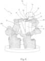
- the guide 1 associated with a vertebracan be seen in figure 4 : the front part seen in figure 4 is the caudal area, while the opposite part, not seen, is the cranial one.
- first 7 and second 8 slotted bodieshave respective extension surfaces 7' and 8', which define the cutting planes, converging below the proximal opening 2p of the respective tubular guide member 2.
- the polyhedral blocks 10further comprise a third 9 and a fourth 11 slotted body, associated in pairs with a respective tubular guide member 2.
- These third 9 and fourth 11 slotted bodiesare opposite each other with respect to the corresponding tubular guide member 2 associated therewith, and arranged on the sides of the first 7 and second 8 slotted bodies, respectively.
- the third 9 and fourth 11 slotted bodiesare placed between the first 7 and second 8 slotted bodies.
- the third 9 and fourth 11 slotted bodieshave respective extension surfaces 9' and 11', which define the cutting planes, arranged transversely to the extension surfaces of the first 7 and second 8 slotted bodies.
- the third 9 and fourth 11 slotted bodiesabut on the transverse process and the lamina, respectively, which should be cut.
- the four slotted bodiesare connected to the respective tubular guide members directly or by means of connecting structures 15
- the extension surfaces of the slotted bodiesare planned by the surgeon, and the inclination thereof is determined in the preoperative step according to the patient's anatomy and the vertebra portion to be dissected.
- the inclination of the extension surfaces 9 ⁇ , 11' defining the cutting planes of the third 9 and fourth 11 slotted bodiesmay vary about a longitudinal and/or sagittal axis of the patient.
- the four slotted bodiesmay not be communicating with one another, thus the slots defining the cutting surfaces may be separated from one another or, as shown incidentally in the accompanying drawings, may be mutually communicating. Therefore, the third 9 and/or fourth 11 slotted bodies may be communicating with the first 7 or second 8 slotted body to define a continuous U-shaped slot.
- the connecting bridge 4comprises pre-weakening lines 12 and a breaking tool 13 to cause the breakage and removal of the bridge itself, so that the surgeon may have, once the guide is positioned and fixed on the vertebra, better visibility of the central area of the vertebra.
- the connecting bridge 4further comprises a handle 14, placed above the area surmounting the spinous process, thus above the apex 5, in order to keep the guide in a stable position, during the first steps of positioning and connecting the guide to the vertebra, and to remove the part of the bridge upon the breakage to leave the central area of the vertebra free.
- the cutting guide 1is used to perform resections of the following vertebral parts: transverse process, lamina, and vertebral body.
- the cutting guideis positioned on the vertebra to be dissected and stabilized by means of the contact members shaped according to the specific patient's anatomy. Holes are then drilled with a surgical instrument through the tubular guide members and screws are then placed to fix the guide to the vertebra.
- the transverse processes and the laminaeare then resected through the appropriate housings defined by the third 9 and fourth 11 slotted bodies.
- the central part of the guidespecifically the connecting bridge 4
- the connecting bridge 4may be separated from the polyhedral blocks 10, by rotating the breaking tool 13 and leveraging the pre-weakening lines 12, and then removed so as to have a better visibility of the central area of the vertebra.
- the cranial and caudal housings, defined by the first 7 and second 8 slotted bodiesare used to resect the vertebral body.
- the handle 14allows keeping more easily the guide in place and leverage more easily during the breaking of the central part of the guide, i.e., of the bridge 4.
- the main innovationis the possibility of performing vertebral resections by means of specific housings, thus of slotted bodies, according to the size of the instrument used.
- the cutting planes of these resectionsare planned by the surgeon and are precisely represented by the slotted bodies, through which the cutting blades are inserted, for the resection of the vertebral parts.
- the axial cavities present in the tubular guide membersallow fixing the guide to the vertebra in order to reduce any movement of the guide itself when the cuts are made.
Landscapes
- Health & Medical Sciences (AREA)
- Surgery (AREA)
- Orthopedic Medicine & Surgery (AREA)
- Life Sciences & Earth Sciences (AREA)
- Biomedical Technology (AREA)
- Public Health (AREA)
- Veterinary Medicine (AREA)
- Engineering & Computer Science (AREA)
- Nuclear Medicine, Radiotherapy & Molecular Imaging (AREA)
- Heart & Thoracic Surgery (AREA)
- Medical Informatics (AREA)
- Molecular Biology (AREA)
- Animal Behavior & Ethology (AREA)
- General Health & Medical Sciences (AREA)
- Dentistry (AREA)
- Oral & Maxillofacial Surgery (AREA)
- Surgical Instruments (AREA)
- Organic Low-Molecular-Weight Compounds And Preparation Thereof (AREA)
Description
- The present invention relates to a cutting guide for spinal osteotomy.
- In the case of spinal deformities such as hyperkyphosis, lordosis or degenerative diseases, there is an unnatural curvature of the patient's spine. Therefore, there is no inter-disc space, with consequent deformation of the patient's posture and compression of the spinal cord.
- When it is necessary to intervene to straighten the spine, a portion of the vertebral column needs to be removed and the vertebrae forced to take a correct anatomical shape. A commonly used technique is pedicle subtraction osteotomy (PSO), which allows obtaining excellent corrections of the deformity associated with a clinical and radiological improvement.
- This procedure is used to fix kyphotic segments. A wedge-shaped incision is made to remove a triangle of bone, having its vertex facing anteriorly with respect to the patient's body, so that the vertebrae can be bent rearwards and brought closer to come into contact posteriorly.
- Such a technique is particularly powerful, especially in the lumbar spine where the vertebrae are larger, and small corrections can lead to large improvements in posture.
- The surgery usually consists in cutting a wedge-shaped portion of the vertebra to create a space which allows the vertebral column to be straightened.
- Stiffening bars are then positioned and fixed with appropriate screws.
- The cuts for osteotomy are currently made freehand without the aid of tools to guide the cutting blade; as a result, the cuts may be inaccurate, even though they may be planned on x-ray or CT scan before the surgery. A further difficulty of the current surgical technique consists in identifying the correct incision depth of the cut which must arrive in the vicinity of the medullary canal. Therefore, the vertebral bone structure is not completely severed but the last portion of the bone is broken manually.
- This is to avoid also affecting the medullary canal with a complete cut, with consequent damage to the patient.
- The front part of the vertebra(e) is removed by hand, taking as a reference the planes created with the removal of the rear part.
- Moreover, a further complication of the current surgical technique is the inclination of the cutting planes, which are not always easy to identify intraoperatively.
- In fact, there are no navigation systems for performing osteotomies on the vertebral column which give the surgeon a precise and sure reference of the incision line and depth.
- Upon the osteotomy, the vertebral column needs to be realigned, which procedure requires the stabilization of the vertebrae not affected by the osteotomy, in the new desired shape by means of stiffening bars fixed to the vertebrae through pedicle screws.
US2017135706 A1 discloses patient-specific cutting guides fabricated from patient anatomical data.- It is the object of the present invention to overcome the drawbacks of the prior art.
- In particular, it is the object of the present invention to suggest a cutting guide for spinal osteotomy which is specific for the patient.
- It is a further object of the present invention to provide a cutting guide for spinal osteotomy which exactly identifies the planes along which the surgeon must cut the vertebrae, thus facilitating the surgery itself as well as ensuring greater safety for the patient.
- It is another object of the present invention to provide a cutting guide for spinal osteotomy which is capable of defining a pre-defined cutting depth which ensures the exact incision depth, avoiding the risk of damage to the medullary canal.
- Furthermore, last but not least, an object of the present invention to provide a cutting guide which allows it to be fixed to the vertebra itself by means of screws, so as to allow the surgeon to make a precise and safe cut of the vertebra portion to be removed.
- These and further objects and advantages are achieved by a cutting guide for spinal osteotomy as disclosed in the appended claims.
- The present invention includes a cutting guide for spinal osteotomy which comprises two polyhedral blocks, each comprising a respective tubular guide member, as presented in claim 1. Preferred embodiments are set forth in the dependent claims.
- Each tubular guide member extends from a proximal opening to a distal opening and has an axial cavity, to guide the insertion of a surgical instrument on a patient's vertebra, extending along a longitudinal axis. A connecting bridge, which connects said two polyhedral blocks to each other, is adapted to surmount a spinous process of the vertebra. The guide further comprises contact members designed to match a corresponding plurality of surfaces or points of contact on the patient's vertebra, in order to define a unique coupling configuration of the cutting guide on the patient's vertebra. The polyhedral blocks each comprise at least a first and a second slotted body, associated in pairs with a respective tubular guide member, arranged one opposite the other with respect to the corresponding tubular guide member associated therewith. The first and second slotted bodies have respective extension surfaces, which define the cutting planes, converging below the proximal opening of the respective tubular guide member.
- The first and second slotted bodies are arranged about the respective tubular guide member, in the caudal and cranial position, respectively, considering the cutting guide in a position of coupling with the corresponding vertebra.
- The guide further comprises a third and a fourth slotted body, associated in pairs with a respective tubular guide member; the third slotted body is arranged opposite the fourth slotted body, with respect to the corresponding tubular guide member associated therewith. Advantageously, the third and fourth slotted bodies are arranged on the sides of the first and second slotted bodies of each tubular guide member, respectively, so that each tubular guide member is associated with the four slotted bodies. Preferably, the third and fourth slotted members are interposed between the first and second slotted bodies.
- The third and fourth slotted bodies also have respective extension surfaces, which define cutting planes. The extension surfaces are transverse to the extension surfaces of the first and second slotted bodies. The extension surfaces of all the slotted bodies are planned by the surgeon and the inclination thereof is determined in the preoperative step according to the patient's anatomy and the vertebra to be dissected.
- The inclination of the extension surfaces, defining the cutting planes, of the slotted bodies may vary about a longitudinal and/or sagittal axis of the patient.
- In some surgical situations, the third and/or fourth slotted bodies may be communicating with the first or second slotted body, to define a continuous U-shaped slot.
- Advantageously, the connecting bridge comprises pre-weakening lines close to the area of connection with the tubular guide members and a breaking tool to cause the breakage and removal of the bridge itself, so that the surgeon has better visibility of the central area of the vertebra.
- The connecting bridge also has a lower surface shaped according to the patient's anatomy, so as to rest on the spinous process of the vertebra in a unique and stable manner.
- The connecting bridge further comprises a handle, preferably placed above the area surmounting the spinous process, in order to keep the guide in place and facilitate the removal of the bridge part separated from the rest of the guide upon the breakage.
- The present invention will become clearer from the following detailed description, with reference to the accompanying drawings:
figure 1 shows a perspective view, from the caudal side, of a cutting guide for spinal osteotomy according to the present invention;figure 2 shows a perspective view, from the cranial side, of the cutting guide for spinal osteotomy according to the present invention;figure 3 shows a lower perspective view of the cutting guide according to the present invention;figure 4 shows a perspective view, from the caudal side, of the cutting guide for spinal osteotomy according to the present invention associated with a vertebra;figure 5 shows a perspective view, from the cranial side, of the cutting guide for spinal osteotomy according to the present invention associated with a vertebra;figure 6 shows a side view of the cutting guide, according to the present invention, associated with a vertebra.- In the aforementioned drawings, reference numeral 1 generally indicates a cutting guide for spinal osteotomy in accordance with the present invention.
- The cutting guide 1, described below, is used to perform cuts according to cutting plans planned before the surgery, in accordance with the specifications provided by the surgeon, on a
specific vertebra 100 or fusion of two or more vertebrae. Such a guide 1 thus serves to make incisions, preferably wedge-shaped, on one or more vertebrae, after which it is possible to remove even significant portions of vertebrae or parts of vertebrae, in order to proceed with straightening the vertebral column. - The cutting guide 1 of the present invention is also a navigation guide which allows precisely guiding surgical instruments, such as drill bits, pedicle screws or Kirchner wires, directly on the vertebra, in a precise selected point, so as to make a pre-hole or to implant the screws which will be used to fix the cutting guide to the vertebra, for example, in order to reduce possible movements of the guide itself during the cutting operations.
- More specifically, the cutting guide 1 comprises two
polyhedral blocks 10, each of which comprises a respectivetubular guide member 2. - Therefore, the cutting guide 1 comprises two
tubular guide members 2, adapted to guide the insertion of a respective surgical instrument, such as drill bits, pedicle screws or Kirchner wires, on a patient'svertebra 100. Eachtubular guide member 2 has an axial cavity 3, extending along alongitudinal axis 2a, to guide the insertion of the aforementioned surgical instruments up to thevertebra 100. Furthermore, eachtubular guide member 2 extends from a proximal opening 2p, adapted to face thevertebra 100, to a distal opening 2d, opposite the proximal opening 2p, and facing upwards when the guide is in use, associated with a patient's vertebrae. - The proximal opening 2p and the distal opening 2d are placed at the ends of the axial cavity 3.
- Therefore, the term "proximal" means the part closest to the patient's body, while the term "distal" refers to the part farthest from the patient's body, considering the guide in a configuration of use, associated with the patient's
vertebra 100. - As can be seen in the accompanying drawings, the cutting guide 1 further comprises a connecting bridge 4, which connects the two
polyhedral blocks 10 to each other and therefore, as a result, thetubular guide members 2. The bridge 4 is adapted to surmount aspinous process 101 of thevertebra 100. - Preferably, the bridge has an apex 5 which, in the configuration of use, is adapted to position and abut just above the spinous process of the vertebra.
- The cutting guide 1 is provided with a plurality of contact members 6 designed to match with a corresponding plurality of surfaces or points of contact on the patient's
vertebra 100, in order to define a unique coupling configuration of the cutting guide 1 on the patient's vertebra. Such contact members 6 are arranged below the twopolyhedral blocks 10, or projecting like a finger from the latter (as can be seen infigure 1 , for example) and below the connecting bridge 4, in particular below the apex 5 of the connecting bridge 4. - Specifically, the contact members, both those located below the polyhedral blocks 10 and those located below the bridge, thus the lower surface of the bridge, including the apex, are shaped according to the patient's anatomy so as to rest on the vertebra in a unique and stable manner.
- The polyhedral blocks 10 each comprise at least a first 7 and a second 8 slotted body, associated in pairs with a respective
tubular guide member 2. The first 7 and second 8 slotted bodies are opposite each other with respect to the correspondingtubular guide member 2 associated therewith. - In particular, the first 7 and second 8 slotted bodies are arranged about the respective
tubular guide member 2 in the caudal and cranial position, respectively, considering the cutting guide 1 in a position of coupling with thevertebra 100. The guide 1 associated with a vertebra can be seen infigure 4 : the front part seen infigure 4 is the caudal area, while the opposite part, not seen, is the cranial one. - The same guide associated with the same vertebra in
figure 4 is also shown infigure 5 , but oriented in the opposite direction: the front part seen infigure 5 is the cranial area, while the opposite part, not seen, is the caudal one. - As can be clearly seen in the accompanying drawings, the first 7 and second 8 slotted bodies have respective extension surfaces 7' and 8', which define the cutting planes, converging below the proximal opening 2p of the respective
tubular guide member 2. - The polyhedral blocks 10 further comprise a third 9 and a fourth 11 slotted body, associated in pairs with a respective
tubular guide member 2. These third 9 and fourth 11 slotted bodies are opposite each other with respect to the correspondingtubular guide member 2 associated therewith, and arranged on the sides of the first 7 and second 8 slotted bodies, respectively. As can be seen in the accompanying drawings, the third 9 and fourth 11 slotted bodies are placed between the first 7 and second 8 slotted bodies. Specifically, the third 9 and fourth 11 slotted bodies have respective extension surfaces 9' and 11', which define the cutting planes, arranged transversely to the extension surfaces of the first 7 and second 8 slotted bodies. - The third 9 and fourth 11 slotted bodies abut on the transverse process and the lamina, respectively, which should be cut.
- The four slotted bodies are connected to the respective tubular guide members directly or by means of connecting structures 15
- The extension surfaces of the slotted bodies, thus not only of the first 7 and second 8 slotted bodies, but also those of the third 9 and fourth 11 slotted bodies, are planned by the surgeon, and the inclination thereof is determined in the preoperative step according to the patient's anatomy and the vertebra portion to be dissected.
- The inclination of the extension surfaces 9`, 11' defining the cutting planes of the third 9 and fourth 11 slotted bodies may vary about a longitudinal and/or sagittal axis of the patient.
- The four slotted bodies may not be communicating with one another, thus the slots defining the cutting surfaces may be separated from one another or, as shown incidentally in the accompanying drawings, may be mutually communicating. Therefore, the third 9 and/or fourth 11 slotted bodies may be communicating with the first 7 or second 8 slotted body to define a continuous U-shaped slot.
- As can be seen in
figures 1 and4 , the connecting bridge 4 comprisespre-weakening lines 12 and abreaking tool 13 to cause the breakage and removal of the bridge itself, so that the surgeon may have, once the guide is positioned and fixed on the vertebra, better visibility of the central area of the vertebra. - The connecting bridge 4 further comprises a
handle 14, placed above the area surmounting the spinous process, thus above the apex 5, in order to keep the guide in a stable position, during the first steps of positioning and connecting the guide to the vertebra, and to remove the part of the bridge upon the breakage to leave the central area of the vertebra free. - In use, the cutting guide 1 is used to perform resections of the following vertebral parts: transverse process, lamina, and vertebral body.
- The cutting guide is positioned on the vertebra to be dissected and stabilized by means of the contact members shaped according to the specific patient's anatomy. Holes are then drilled with a surgical instrument through the tubular guide members and screws are then placed to fix the guide to the vertebra.
- The transverse processes and the laminae are then resected through the appropriate housings defined by the third 9 and fourth 11 slotted bodies. After this step, the central part of the guide, specifically the connecting bridge 4, may be separated from the polyhedral blocks 10, by rotating the
breaking tool 13 and leveraging thepre-weakening lines 12, and then removed so as to have a better visibility of the central area of the vertebra. Finally, the cranial and caudal housings, defined by the first 7 and second 8 slotted bodies, are used to resect the vertebral body. - The
handle 14 allows keeping more easily the guide in place and leverage more easily during the breaking of the central part of the guide, i.e., of the bridge 4. - The main innovation is the possibility of performing vertebral resections by means of specific housings, thus of slotted bodies, according to the size of the instrument used.
- The cutting planes of these resections are planned by the surgeon and are precisely represented by the slotted bodies, through which the cutting blades are inserted, for the resection of the vertebral parts.
- The axial cavities present in the tubular guide members allow fixing the guide to the vertebra in order to reduce any movement of the guide itself when the cuts are made.
- Furthermore, the possibility of removing the central part of the guide, using a breaking tool, helps the surgeon to have a wider view of the resection area.
Claims (10)
- A cutting guide (1) for spinal osteotomy, comprising two polyhedral blocks (10), each comprising a respective tubular guide member (2); each tubular guide member (2) extending from a proximal opening (2p) to a distal opening (2d) and having an axial cavity (3), to guide the insertion of a surgical instrument on a patient's vertebra (100), extending along a longitudinal axis (2a); a connecting bridge (4), which connects said two polyhedral blocks (10) to each other, adapted to surmount a spinous process (101) of said vertebra (100), contact members (6) designed to match a corresponding plurality of surfaces or points of contact on the patient's vertebra (100) in order to define a unique coupling configuration of the cutting guide (1) on the patient's vertebra (100),characterized in that said polyhedral blocks (10) each comprise at least a first (7) and a second (8) slotted body; said first (7) and second (8) slotted body being associated in pairs with a respective tubular guide member (2) and being arranged one opposite the other with respect to the corresponding tubular guide member (2) associated therewith; said first (7) and second (8) slotted bodies having respective extension surfaces (7', 8'), which define cutting planes, converging below the proximal opening (2p) of the respective tubular guide member (2).
- A cutting guide according to the preceding claim,characterized in that said first (7) and second (8) slotted bodies are arranged about the respective tubular guide member (2) in caudal and cranial position, respectively, considering the cutting guide (1) in a position of coupling with said vertebra (100).
- A cutting guide according to one of the preceding claims,characterized in that it comprises a third (9) and a fourth (11) slotted body, associated in pairs with a respective tubular guide member (2), arranged one opposite the other with respect to the corresponding tubular guide member (2) associated therewith, and arranged on the sides of the first (7) and second (8) slotted bodies, respectively.
- A cutting guide according to the preceding claim,characterized in that said third (9) and fourth (11) slotted bodies have respective extension surfaces (9', 11'), which define the cutting planes, transversal with respect to the extension surfaces of said first (7) and second (8) slotted bodies.
- A cutting guide according to the preceding claim,characterized in that said extension surfaces (7', 8', 9`, 11') and the inclination thereof are determined preoperatively according to the patient's anatomy and the vertebra to be dissected.
- A cutting guide according to claim 5,characterized in that the inclination of the extension surfaces (9', 11'), defining the cutting planes, of said third (9) and fourth (11) slotted bodies may vary about a longitudinal and/or sagittal axis of the patient.
- A cutting guide according to claim 3,characterized in that said third (9) and/or fourth (11) slotted bodies may communicate with said first (7) or said second (8) slotted body to define a continuous U-shaped slot.
- A cutting guide according to one of the preceding claims,characterized in that said connecting bridge (4) comprises pre-weakening lines (12) and a breaking tool (13) to cause the breakage and removal of the bridge itself.
- A cutting guide according to one of the preceding claims,characterized in that said connecting bridge (4) has a lower surface shaped according to the patient's anatomy so as to rest on the spinous process (101) of said vertebra.
- A cutting guide according to one of the preceding claims,characterized in that said connecting bridge (4) comprises a handle (14), placed above the area surmounting the spinous process, in order to keep the guide in a stable position.
Applications Claiming Priority (2)
| Application Number | Priority Date | Filing Date | Title |
|---|---|---|---|
| IT102020000020794AIT202000020794A1 (en) | 2020-09-01 | 2020-09-01 | CUTTING GUIDE FOR SPINAL OSTEOTOMY |
| PCT/IB2021/057547WO2022049435A1 (en) | 2020-09-01 | 2021-08-17 | Cutting guide for spinal osteotomy |
Publications (2)
| Publication Number | Publication Date |
|---|---|
| EP4208105A1 EP4208105A1 (en) | 2023-07-12 |
| EP4208105B1true EP4208105B1 (en) | 2024-06-12 |
Family
ID=73401907
Family Applications (1)
| Application Number | Title | Priority Date | Filing Date |
|---|---|---|---|
| EP21770062.4AActiveEP4208105B1 (en) | 2020-09-01 | 2021-08-17 | Cutting guide for spinal osteotomy |
Country Status (7)
| Country | Link |
|---|---|
| US (1) | US12343023B2 (en) |
| EP (1) | EP4208105B1 (en) |
| JP (1) | JP7432795B2 (en) |
| AU (1) | AU2021336812B2 (en) |
| ES (1) | ES2985424T3 (en) |
| IT (1) | IT202000020794A1 (en) |
| WO (1) | WO2022049435A1 (en) |
Families Citing this family (4)
| Publication number | Priority date | Publication date | Assignee | Title |
|---|---|---|---|---|
| USD1046132S1 (en)* | 2021-11-04 | 2024-10-08 | Medacta International Sa | Surgical instrument |
| USD1047144S1 (en)* | 2021-11-04 | 2024-10-15 | Medacta International Sa | Surgical instrument |
| USD1046131S1 (en)* | 2021-11-04 | 2024-10-08 | Medacta International Sa | Surgical instrument |
| USD1046150S1 (en)* | 2021-11-04 | 2024-10-08 | Medacta International Sa | Surgical instrument |
Family Cites Families (13)
| Publication number | Priority date | Publication date | Assignee | Title |
|---|---|---|---|---|
| KR101859932B1 (en)* | 2010-06-29 | 2018-05-21 | 조지 프레이 | Patient matching surgical guide and method for using the same |
| US9642633B2 (en)* | 2010-06-29 | 2017-05-09 | Mighty Oak Medical, Inc. | Patient-matched apparatus and methods for performing surgical procedures |
| WO2017066518A1 (en)* | 2010-06-29 | 2017-04-20 | Mighty Oak Medical, Inc. | Patient-matched apparatus and methods for performing surgical procedures |
| EP2749235B1 (en)* | 2012-12-31 | 2017-08-09 | Medacta International S.A. | Patient specific operative guide for use in spinal surgery |
| US10433880B2 (en)* | 2013-03-15 | 2019-10-08 | Jcbd, Llc | Systems and methods for fusing a sacroiliac joint and anchoring an orthopedic appliance |
| JP6650451B2 (en)* | 2014-11-14 | 2020-02-19 | メダクタ・インターナショナル・ソシエテ・アノニム | Guidance guide according to patient |
| WO2016149824A1 (en)* | 2015-03-25 | 2016-09-29 | Orthosoft Inc. | Method and system for assisting implant placement in thin bones such as scapula |
| US9962171B2 (en)* | 2015-06-09 | 2018-05-08 | Warsaw Orthopedic, Inc. | Surgical instrument and method |
| JP2018532498A (en)* | 2015-10-14 | 2018-11-08 | マイティ オーク メディカル、インコーポレイテッド | Patient fitting device and method of performing a surgical procedure |
| US10603055B2 (en)* | 2017-09-15 | 2020-03-31 | Jcbd, Llc | Systems for and methods of preparing and fusing a sacroiliac joint |
| EP3466350B1 (en)* | 2017-10-06 | 2020-07-22 | Stryker European Holdings I, LLC | Pedicle subtraction osteotomy guide |
| ES2978217T3 (en)* | 2018-10-08 | 2024-09-09 | Medacta Int Sa | Patient-specific navigation guide |
| IT201900002575A1 (en)* | 2019-02-22 | 2020-08-22 | Medacta Int Sa | CUTTING GUIDE FOR SPINAL OSTEOTOMY |
- 2020
- 2020-09-01ITIT102020000020794Apatent/IT202000020794A1/enunknown
- 2021
- 2021-08-17AUAU2021336812Apatent/AU2021336812B2/enactiveActive
- 2021-08-17ESES21770062Tpatent/ES2985424T3/enactiveActive
- 2021-08-17WOPCT/IB2021/057547patent/WO2022049435A1/ennot_activeCeased
- 2021-08-17JPJP2023513908Apatent/JP7432795B2/enactiveActive
- 2021-08-17USUS18/022,675patent/US12343023B2/enactiveActive
- 2021-08-17EPEP21770062.4Apatent/EP4208105B1/enactiveActive
Also Published As
| Publication number | Publication date |
|---|---|
| EP4208105A1 (en) | 2023-07-12 |
| WO2022049435A1 (en) | 2022-03-10 |
| IT202000020794A1 (en) | 2022-03-01 |
| ES2985424T3 (en) | 2024-11-05 |
| US12343023B2 (en) | 2025-07-01 |
| JP2023539651A (en) | 2023-09-15 |
| JP7432795B2 (en) | 2024-02-16 |
| US20230301668A1 (en) | 2023-09-28 |
| AU2021336812A1 (en) | 2023-03-23 |
| AU2021336812B2 (en) | 2024-07-04 |
Similar Documents
| Publication | Publication Date | Title |
|---|---|---|
| EP4208105B1 (en) | Cutting guide for spinal osteotomy | |
| EP3515333B1 (en) | Patient-specific navigational guide | |
| EP3927253B1 (en) | A cutting guide for spinal osteotomy | |
| EP2749235B1 (en) | Patient specific operative guide for use in spinal surgery | |
| EP3863532B1 (en) | Patient-specific navigation guide | |
| EP2914187B1 (en) | Patient-specific sacroiliac and pedicle guides | |
| EP3217897B1 (en) | Patient-specific navigational guide | |
| EP2851022B1 (en) | Lumbar-sacral screw insertion and manipulation | |
| EP3466350B1 (en) | Pedicle subtraction osteotomy guide | |
| US6126664A (en) | Device and method for locating and resecting bone | |
| US9408716B1 (en) | Percutaneous posterior spinal fusion implant construction and method | |
| US12127949B1 (en) | Percutaneous posterior spinal fusion implant construction and method | |
| US20250049450A1 (en) | Orthopedic instruments and methods |
Legal Events
| Date | Code | Title | Description |
|---|---|---|---|
| STAA | Information on the status of an ep patent application or granted ep patent | Free format text:STATUS: UNKNOWN | |
| STAA | Information on the status of an ep patent application or granted ep patent | Free format text:STATUS: THE INTERNATIONAL PUBLICATION HAS BEEN MADE | |
| PUAI | Public reference made under article 153(3) epc to a published international application that has entered the european phase | Free format text:ORIGINAL CODE: 0009012 | |
| STAA | Information on the status of an ep patent application or granted ep patent | Free format text:STATUS: REQUEST FOR EXAMINATION WAS MADE | |
| 17P | Request for examination filed | Effective date:20230120 | |
| AK | Designated contracting states | Kind code of ref document:A1 Designated state(s):AL AT BE BG CH CY CZ DE DK EE ES FI FR GB GR HR HU IE IS IT LI LT LU LV MC MK MT NL NO PL PT RO RS SE SI SK SM TR | |
| P01 | Opt-out of the competence of the unified patent court (upc) registered | Effective date:20230714 | |
| DAV | Request for validation of the european patent (deleted) | ||
| DAX | Request for extension of the european patent (deleted) | ||
| GRAP | Despatch of communication of intention to grant a patent | Free format text:ORIGINAL CODE: EPIDOSNIGR1 | |
| STAA | Information on the status of an ep patent application or granted ep patent | Free format text:STATUS: GRANT OF PATENT IS INTENDED | |
| INTG | Intention to grant announced | Effective date:20240117 | |
| GRAS | Grant fee paid | Free format text:ORIGINAL CODE: EPIDOSNIGR3 | |
| GRAA | (expected) grant | Free format text:ORIGINAL CODE: 0009210 | |
| STAA | Information on the status of an ep patent application or granted ep patent | Free format text:STATUS: THE PATENT HAS BEEN GRANTED | |
| AK | Designated contracting states | Kind code of ref document:B1 Designated state(s):AL AT BE BG CH CY CZ DE DK EE ES FI FR GB GR HR HU IE IS IT LI LT LU LV MC MK MT NL NO PL PT RO RS SE SI SK SM TR | |
| REG | Reference to a national code | Ref country code:GB Ref legal event code:FG4D | |
| REG | Reference to a national code | Ref country code:CH Ref legal event code:EP | |
| REG | Reference to a national code | Ref country code:IE Ref legal event code:FG4D | |
| REG | Reference to a national code | Ref country code:DE Ref legal event code:R096 Ref document number:602021014435 Country of ref document:DE | |
| PG25 | Lapsed in a contracting state [announced via postgrant information from national office to epo] | Ref country code:BG Free format text:LAPSE BECAUSE OF FAILURE TO SUBMIT A TRANSLATION OF THE DESCRIPTION OR TO PAY THE FEE WITHIN THE PRESCRIBED TIME-LIMIT Effective date:20240612 | |
| PG25 | Lapsed in a contracting state [announced via postgrant information from national office to epo] | Ref country code:HR Free format text:LAPSE BECAUSE OF FAILURE TO SUBMIT A TRANSLATION OF THE DESCRIPTION OR TO PAY THE FEE WITHIN THE PRESCRIBED TIME-LIMIT Effective date:20240612 Ref country code:FI Free format text:LAPSE BECAUSE OF FAILURE TO SUBMIT A TRANSLATION OF THE DESCRIPTION OR TO PAY THE FEE WITHIN THE PRESCRIBED TIME-LIMIT Effective date:20240612 | |
| PGFP | Annual fee paid to national office [announced via postgrant information from national office to epo] | Ref country code:DE Payment date:20240828 Year of fee payment:4 | |
| REG | Reference to a national code | Ref country code:LT Ref legal event code:MG9D | |
| PG25 | Lapsed in a contracting state [announced via postgrant information from national office to epo] | Ref country code:GR Free format text:LAPSE BECAUSE OF FAILURE TO SUBMIT A TRANSLATION OF THE DESCRIPTION OR TO PAY THE FEE WITHIN THE PRESCRIBED TIME-LIMIT Effective date:20240913 | |
| PGFP | Annual fee paid to national office [announced via postgrant information from national office to epo] | Ref country code:FR Payment date:20240826 Year of fee payment:4 | |
| REG | Reference to a national code | Ref country code:NL Ref legal event code:MP Effective date:20240612 | |
| PGFP | Annual fee paid to national office [announced via postgrant information from national office to epo] | Ref country code:CH Payment date:20240901 Year of fee payment:4 | |
| PG25 | Lapsed in a contracting state [announced via postgrant information from national office to epo] | Ref country code:LV Free format text:LAPSE BECAUSE OF FAILURE TO SUBMIT A TRANSLATION OF THE DESCRIPTION OR TO PAY THE FEE WITHIN THE PRESCRIBED TIME-LIMIT Effective date:20240612 | |
| PG25 | Lapsed in a contracting state [announced via postgrant information from national office to epo] | Ref country code:NO Free format text:LAPSE BECAUSE OF FAILURE TO SUBMIT A TRANSLATION OF THE DESCRIPTION OR TO PAY THE FEE WITHIN THE PRESCRIBED TIME-LIMIT Effective date:20240912 Ref country code:LV Free format text:LAPSE BECAUSE OF FAILURE TO SUBMIT A TRANSLATION OF THE DESCRIPTION OR TO PAY THE FEE WITHIN THE PRESCRIBED TIME-LIMIT Effective date:20240612 Ref country code:HR Free format text:LAPSE BECAUSE OF FAILURE TO SUBMIT A TRANSLATION OF THE DESCRIPTION OR TO PAY THE FEE WITHIN THE PRESCRIBED TIME-LIMIT Effective date:20240612 Ref country code:GR Free format text:LAPSE BECAUSE OF FAILURE TO SUBMIT A TRANSLATION OF THE DESCRIPTION OR TO PAY THE FEE WITHIN THE PRESCRIBED TIME-LIMIT Effective date:20240913 Ref country code:FI Free format text:LAPSE BECAUSE OF FAILURE TO SUBMIT A TRANSLATION OF THE DESCRIPTION OR TO PAY THE FEE WITHIN THE PRESCRIBED TIME-LIMIT Effective date:20240612 Ref country code:BG Free format text:LAPSE BECAUSE OF FAILURE TO SUBMIT A TRANSLATION OF THE DESCRIPTION OR TO PAY THE FEE WITHIN THE PRESCRIBED TIME-LIMIT Effective date:20240612 Ref country code:RS Free format text:LAPSE BECAUSE OF FAILURE TO SUBMIT A TRANSLATION OF THE DESCRIPTION OR TO PAY THE FEE WITHIN THE PRESCRIBED TIME-LIMIT Effective date:20240912 | |
| PGFP | Annual fee paid to national office [announced via postgrant information from national office to epo] | Ref country code:IT Payment date:20240831 Year of fee payment:4 | |
| REG | Reference to a national code | Ref country code:ES Ref legal event code:FG2A Ref document number:2985424 Country of ref document:ES Kind code of ref document:T3 Effective date:20241105 | |
| PG25 | Lapsed in a contracting state [announced via postgrant information from national office to epo] | Ref country code:NL Free format text:LAPSE BECAUSE OF FAILURE TO SUBMIT A TRANSLATION OF THE DESCRIPTION OR TO PAY THE FEE WITHIN THE PRESCRIBED TIME-LIMIT Effective date:20240612 | |
| REG | Reference to a national code | Ref country code:AT Ref legal event code:MK05 Ref document number:1693547 Country of ref document:AT Kind code of ref document:T Effective date:20240612 | |
| PG25 | Lapsed in a contracting state [announced via postgrant information from national office to epo] | Ref country code:NL Free format text:LAPSE BECAUSE OF FAILURE TO SUBMIT A TRANSLATION OF THE DESCRIPTION OR TO PAY THE FEE WITHIN THE PRESCRIBED TIME-LIMIT Effective date:20240612 | |
| PG25 | Lapsed in a contracting state [announced via postgrant information from national office to epo] | Ref country code:PT Free format text:LAPSE BECAUSE OF FAILURE TO SUBMIT A TRANSLATION OF THE DESCRIPTION OR TO PAY THE FEE WITHIN THE PRESCRIBED TIME-LIMIT Effective date:20241014 | |
| PG25 | Lapsed in a contracting state [announced via postgrant information from national office to epo] | Ref country code:PT Free format text:LAPSE BECAUSE OF FAILURE TO SUBMIT A TRANSLATION OF THE DESCRIPTION OR TO PAY THE FEE WITHIN THE PRESCRIBED TIME-LIMIT Effective date:20241014 | |
| PG25 | Lapsed in a contracting state [announced via postgrant information from national office to epo] | Ref country code:PL Free format text:LAPSE BECAUSE OF FAILURE TO SUBMIT A TRANSLATION OF THE DESCRIPTION OR TO PAY THE FEE WITHIN THE PRESCRIBED TIME-LIMIT Effective date:20240612 | |
| PG25 | Lapsed in a contracting state [announced via postgrant information from national office to epo] | Ref country code:EE Free format text:LAPSE BECAUSE OF FAILURE TO SUBMIT A TRANSLATION OF THE DESCRIPTION OR TO PAY THE FEE WITHIN THE PRESCRIBED TIME-LIMIT Effective date:20240612 | |
| PG25 | Lapsed in a contracting state [announced via postgrant information from national office to epo] | Ref country code:IS Free format text:LAPSE BECAUSE OF FAILURE TO SUBMIT A TRANSLATION OF THE DESCRIPTION OR TO PAY THE FEE WITHIN THE PRESCRIBED TIME-LIMIT Effective date:20241012 Ref country code:AT Free format text:LAPSE BECAUSE OF FAILURE TO SUBMIT A TRANSLATION OF THE DESCRIPTION OR TO PAY THE FEE WITHIN THE PRESCRIBED TIME-LIMIT Effective date:20240612 | |
| PG25 | Lapsed in a contracting state [announced via postgrant information from national office to epo] | Ref country code:CZ Free format text:LAPSE BECAUSE OF FAILURE TO SUBMIT A TRANSLATION OF THE DESCRIPTION OR TO PAY THE FEE WITHIN THE PRESCRIBED TIME-LIMIT Effective date:20240612 | |
| PG25 | Lapsed in a contracting state [announced via postgrant information from national office to epo] | Ref country code:RO Free format text:LAPSE BECAUSE OF FAILURE TO SUBMIT A TRANSLATION OF THE DESCRIPTION OR TO PAY THE FEE WITHIN THE PRESCRIBED TIME-LIMIT Effective date:20240612 Ref country code:SK Free format text:LAPSE BECAUSE OF FAILURE TO SUBMIT A TRANSLATION OF THE DESCRIPTION OR TO PAY THE FEE WITHIN THE PRESCRIBED TIME-LIMIT Effective date:20240612 | |
| PG25 | Lapsed in a contracting state [announced via postgrant information from national office to epo] | Ref country code:SM Free format text:LAPSE BECAUSE OF FAILURE TO SUBMIT A TRANSLATION OF THE DESCRIPTION OR TO PAY THE FEE WITHIN THE PRESCRIBED TIME-LIMIT Effective date:20240612 | |
| PG25 | Lapsed in a contracting state [announced via postgrant information from national office to epo] | Ref country code:SM Free format text:LAPSE BECAUSE OF FAILURE TO SUBMIT A TRANSLATION OF THE DESCRIPTION OR TO PAY THE FEE WITHIN THE PRESCRIBED TIME-LIMIT Effective date:20240612 Ref country code:SK Free format text:LAPSE BECAUSE OF FAILURE TO SUBMIT A TRANSLATION OF THE DESCRIPTION OR TO PAY THE FEE WITHIN THE PRESCRIBED TIME-LIMIT Effective date:20240612 Ref country code:RO Free format text:LAPSE BECAUSE OF FAILURE TO SUBMIT A TRANSLATION OF THE DESCRIPTION OR TO PAY THE FEE WITHIN THE PRESCRIBED TIME-LIMIT Effective date:20240612 Ref country code:PL Free format text:LAPSE BECAUSE OF FAILURE TO SUBMIT A TRANSLATION OF THE DESCRIPTION OR TO PAY THE FEE WITHIN THE PRESCRIBED TIME-LIMIT Effective date:20240612 Ref country code:IS Free format text:LAPSE BECAUSE OF FAILURE TO SUBMIT A TRANSLATION OF THE DESCRIPTION OR TO PAY THE FEE WITHIN THE PRESCRIBED TIME-LIMIT Effective date:20241012 Ref country code:EE Free format text:LAPSE BECAUSE OF FAILURE TO SUBMIT A TRANSLATION OF THE DESCRIPTION OR TO PAY THE FEE WITHIN THE PRESCRIBED TIME-LIMIT Effective date:20240612 Ref country code:CZ Free format text:LAPSE BECAUSE OF FAILURE TO SUBMIT A TRANSLATION OF THE DESCRIPTION OR TO PAY THE FEE WITHIN THE PRESCRIBED TIME-LIMIT Effective date:20240612 Ref country code:AT Free format text:LAPSE BECAUSE OF FAILURE TO SUBMIT A TRANSLATION OF THE DESCRIPTION OR TO PAY THE FEE WITHIN THE PRESCRIBED TIME-LIMIT Effective date:20240612 | |
| REG | Reference to a national code | Ref country code:DE Ref legal event code:R097 Ref document number:602021014435 Country of ref document:DE | |
| PG25 | Lapsed in a contracting state [announced via postgrant information from national office to epo] | Ref country code:DK Free format text:LAPSE BECAUSE OF FAILURE TO SUBMIT A TRANSLATION OF THE DESCRIPTION OR TO PAY THE FEE WITHIN THE PRESCRIBED TIME-LIMIT Effective date:20240612 | |
| PG25 | Lapsed in a contracting state [announced via postgrant information from national office to epo] | Ref country code:LU Free format text:LAPSE BECAUSE OF NON-PAYMENT OF DUE FEES Effective date:20240817 | |
| PLBE | No opposition filed within time limit | Free format text:ORIGINAL CODE: 0009261 | |
| STAA | Information on the status of an ep patent application or granted ep patent | Free format text:STATUS: NO OPPOSITION FILED WITHIN TIME LIMIT | |
| PG25 | Lapsed in a contracting state [announced via postgrant information from national office to epo] | Ref country code:MC Free format text:LAPSE BECAUSE OF FAILURE TO SUBMIT A TRANSLATION OF THE DESCRIPTION OR TO PAY THE FEE WITHIN THE PRESCRIBED TIME-LIMIT Effective date:20240612 | |
| 26N | No opposition filed | Effective date:20250313 | |
| REG | Reference to a national code | Ref country code:BE Ref legal event code:MM Effective date:20240831 | |
| PG25 | Lapsed in a contracting state [announced via postgrant information from national office to epo] | Ref country code:BE Free format text:LAPSE BECAUSE OF NON-PAYMENT OF DUE FEES Effective date:20240831 | |
| PG25 | Lapsed in a contracting state [announced via postgrant information from national office to epo] | Ref country code:IE Free format text:LAPSE BECAUSE OF NON-PAYMENT OF DUE FEES Effective date:20240817 | |
| PG25 | Lapsed in a contracting state [announced via postgrant information from national office to epo] | Ref country code:SE Free format text:LAPSE BECAUSE OF FAILURE TO SUBMIT A TRANSLATION OF THE DESCRIPTION OR TO PAY THE FEE WITHIN THE PRESCRIBED TIME-LIMIT Effective date:20240612 | |
| PGFP | Annual fee paid to national office [announced via postgrant information from national office to epo] | Ref country code:ES Payment date:20250916 Year of fee payment:5 |