EP4202521B1 - Point of view aberrations correction in a scanning folded camera - Google Patents
Point of view aberrations correction in a scanning folded cameraDownload PDFInfo
- Publication number
- EP4202521B1 EP4202521B1EP23157770.1AEP23157770AEP4202521B1EP 4202521 B1EP4202521 B1EP 4202521B1EP 23157770 AEP23157770 AEP 23157770AEP 4202521 B1EP4202521 B1EP 4202521B1
- Authority
- EP
- European Patent Office
- Prior art keywords
- image
- pov
- opfe
- tele
- aberration
- Prior art date
- Legal status (The legal status is an assumption and is not a legal conclusion. Google has not performed a legal analysis and makes no representation as to the accuracy of the status listed.)
- Active
Links
Images


Classifications
- H—ELECTRICITY
- H04—ELECTRIC COMMUNICATION TECHNIQUE
- H04N—PICTORIAL COMMUNICATION, e.g. TELEVISION
- H04N23/00—Cameras or camera modules comprising electronic image sensors; Control thereof
- H04N23/58—Means for changing the camera field of view without moving the camera body, e.g. nutating or panning of optics or image sensors
- G—PHYSICS
- G02—OPTICS
- G02B—OPTICAL ELEMENTS, SYSTEMS OR APPARATUS
- G02B13/00—Optical objectives specially designed for the purposes specified below
- G02B13/02—Telephoto objectives, i.e. systems of the type + - in which the distance from the front vertex to the image plane is less than the equivalent focal length
- G—PHYSICS
- G02—OPTICS
- G02B—OPTICAL ELEMENTS, SYSTEMS OR APPARATUS
- G02B27/00—Optical systems or apparatus not provided for by any of the groups G02B1/00 - G02B26/00, G02B30/00
- G02B27/0025—Optical systems or apparatus not provided for by any of the groups G02B1/00 - G02B26/00, G02B30/00 for optical correction, e.g. distorsion, aberration
- G—PHYSICS
- G02—OPTICS
- G02B—OPTICAL ELEMENTS, SYSTEMS OR APPARATUS
- G02B27/00—Optical systems or apparatus not provided for by any of the groups G02B1/00 - G02B26/00, G02B30/00
- G02B27/0081—Optical systems or apparatus not provided for by any of the groups G02B1/00 - G02B26/00, G02B30/00 with means for altering, e.g. enlarging, the entrance or exit pupil
- G—PHYSICS
- G02—OPTICS
- G02B—OPTICAL ELEMENTS, SYSTEMS OR APPARATUS
- G02B27/00—Optical systems or apparatus not provided for by any of the groups G02B1/00 - G02B26/00, G02B30/00
- G02B27/64—Imaging systems using optical elements for stabilisation of the lateral and angular position of the image
- G02B27/646—Imaging systems using optical elements for stabilisation of the lateral and angular position of the image compensating for small deviations, e.g. due to vibration or shake
- G—PHYSICS
- G02—OPTICS
- G02B—OPTICAL ELEMENTS, SYSTEMS OR APPARATUS
- G02B7/00—Mountings, adjusting means, or light-tight connections, for optical elements
- G02B7/18—Mountings, adjusting means, or light-tight connections, for optical elements for prisms; for mirrors
- G02B7/1805—Mountings, adjusting means, or light-tight connections, for optical elements for prisms; for mirrors for prisms
- G—PHYSICS
- G03—PHOTOGRAPHY; CINEMATOGRAPHY; ANALOGOUS TECHNIQUES USING WAVES OTHER THAN OPTICAL WAVES; ELECTROGRAPHY; HOLOGRAPHY
- G03B—APPARATUS OR ARRANGEMENTS FOR TAKING PHOTOGRAPHS OR FOR PROJECTING OR VIEWING THEM; APPARATUS OR ARRANGEMENTS EMPLOYING ANALOGOUS TECHNIQUES USING WAVES OTHER THAN OPTICAL WAVES; ACCESSORIES THEREFOR
- G03B17/00—Details of cameras or camera bodies; Accessories therefor
- G03B17/02—Bodies
- G03B17/12—Bodies with means for supporting objectives, supplementary lenses, filters, masks, or turrets
- G—PHYSICS
- G03—PHOTOGRAPHY; CINEMATOGRAPHY; ANALOGOUS TECHNIQUES USING WAVES OTHER THAN OPTICAL WAVES; ELECTROGRAPHY; HOLOGRAPHY
- G03B—APPARATUS OR ARRANGEMENTS FOR TAKING PHOTOGRAPHS OR FOR PROJECTING OR VIEWING THEM; APPARATUS OR ARRANGEMENTS EMPLOYING ANALOGOUS TECHNIQUES USING WAVES OTHER THAN OPTICAL WAVES; ACCESSORIES THEREFOR
- G03B17/00—Details of cameras or camera bodies; Accessories therefor
- G03B17/02—Bodies
- G03B17/17—Bodies with reflectors arranged in beam forming the photographic image, e.g. for reducing dimensions of camera
- G—PHYSICS
- G03—PHOTOGRAPHY; CINEMATOGRAPHY; ANALOGOUS TECHNIQUES USING WAVES OTHER THAN OPTICAL WAVES; ELECTROGRAPHY; HOLOGRAPHY
- G03B—APPARATUS OR ARRANGEMENTS FOR TAKING PHOTOGRAPHS OR FOR PROJECTING OR VIEWING THEM; APPARATUS OR ARRANGEMENTS EMPLOYING ANALOGOUS TECHNIQUES USING WAVES OTHER THAN OPTICAL WAVES; ACCESSORIES THEREFOR
- G03B30/00—Camera modules comprising integrated lens units and imaging units, specially adapted for being embedded in other devices, e.g. mobile phones or vehicles
- G—PHYSICS
- G03—PHOTOGRAPHY; CINEMATOGRAPHY; ANALOGOUS TECHNIQUES USING WAVES OTHER THAN OPTICAL WAVES; ELECTROGRAPHY; HOLOGRAPHY
- G03B—APPARATUS OR ARRANGEMENTS FOR TAKING PHOTOGRAPHS OR FOR PROJECTING OR VIEWING THEM; APPARATUS OR ARRANGEMENTS EMPLOYING ANALOGOUS TECHNIQUES USING WAVES OTHER THAN OPTICAL WAVES; ACCESSORIES THEREFOR
- G03B37/00—Panoramic or wide-screen photography; Photographing extended surfaces, e.g. for surveying; Photographing internal surfaces, e.g. of pipe
- G03B37/02—Panoramic or wide-screen photography; Photographing extended surfaces, e.g. for surveying; Photographing internal surfaces, e.g. of pipe with scanning movement of lens or cameras
- G—PHYSICS
- G03—PHOTOGRAPHY; CINEMATOGRAPHY; ANALOGOUS TECHNIQUES USING WAVES OTHER THAN OPTICAL WAVES; ELECTROGRAPHY; HOLOGRAPHY
- G03B—APPARATUS OR ARRANGEMENTS FOR TAKING PHOTOGRAPHS OR FOR PROJECTING OR VIEWING THEM; APPARATUS OR ARRANGEMENTS EMPLOYING ANALOGOUS TECHNIQUES USING WAVES OTHER THAN OPTICAL WAVES; ACCESSORIES THEREFOR
- G03B5/00—Adjustment of optical system relative to image or object surface other than for focusing
- G—PHYSICS
- G06—COMPUTING OR CALCULATING; COUNTING
- G06T—IMAGE DATA PROCESSING OR GENERATION, IN GENERAL
- G06T3/00—Geometric image transformations in the plane of the image
- G06T3/40—Scaling of whole images or parts thereof, e.g. expanding or contracting
- G—PHYSICS
- G06—COMPUTING OR CALCULATING; COUNTING
- G06T—IMAGE DATA PROCESSING OR GENERATION, IN GENERAL
- G06T5/00—Image enhancement or restoration
- G06T5/80—Geometric correction
- G—PHYSICS
- G06—COMPUTING OR CALCULATING; COUNTING
- G06T—IMAGE DATA PROCESSING OR GENERATION, IN GENERAL
- G06T7/00—Image analysis
- G06T7/80—Analysis of captured images to determine intrinsic or extrinsic camera parameters, i.e. camera calibration
- H—ELECTRICITY
- H04—ELECTRIC COMMUNICATION TECHNIQUE
- H04N—PICTORIAL COMMUNICATION, e.g. TELEVISION
- H04N23/00—Cameras or camera modules comprising electronic image sensors; Control thereof
- H04N23/45—Cameras or camera modules comprising electronic image sensors; Control thereof for generating image signals from two or more image sensors being of different type or operating in different modes, e.g. with a CMOS sensor for moving images in combination with a charge-coupled device [CCD] for still images
- H—ELECTRICITY
- H04—ELECTRIC COMMUNICATION TECHNIQUE
- H04N—PICTORIAL COMMUNICATION, e.g. TELEVISION
- H04N23/00—Cameras or camera modules comprising electronic image sensors; Control thereof
- H04N23/50—Constructional details
- H04N23/54—Mounting of pick-up tubes, electronic image sensors, deviation or focusing coils
- H—ELECTRICITY
- H04—ELECTRIC COMMUNICATION TECHNIQUE
- H04N—PICTORIAL COMMUNICATION, e.g. TELEVISION
- H04N23/00—Cameras or camera modules comprising electronic image sensors; Control thereof
- H04N23/50—Constructional details
- H04N23/55—Optical parts specially adapted for electronic image sensors; Mounting thereof
- H—ELECTRICITY
- H04—ELECTRIC COMMUNICATION TECHNIQUE
- H04N—PICTORIAL COMMUNICATION, e.g. TELEVISION
- H04N23/00—Cameras or camera modules comprising electronic image sensors; Control thereof
- H04N23/60—Control of cameras or camera modules
- H04N23/68—Control of cameras or camera modules for stable pick-up of the scene, e.g. compensating for camera body vibrations
- H04N23/681—Motion detection
- H—ELECTRICITY
- H04—ELECTRIC COMMUNICATION TECHNIQUE
- H04N—PICTORIAL COMMUNICATION, e.g. TELEVISION
- H04N23/00—Cameras or camera modules comprising electronic image sensors; Control thereof
- H04N23/60—Control of cameras or camera modules
- H04N23/68—Control of cameras or camera modules for stable pick-up of the scene, e.g. compensating for camera body vibrations
- H04N23/682—Vibration or motion blur correction
- H04N23/683—Vibration or motion blur correction performed by a processor, e.g. controlling the readout of an image memory
- H—ELECTRICITY
- H04—ELECTRIC COMMUNICATION TECHNIQUE
- H04N—PICTORIAL COMMUNICATION, e.g. TELEVISION
- H04N23/00—Cameras or camera modules comprising electronic image sensors; Control thereof
- H04N23/60—Control of cameras or camera modules
- H04N23/698—Control of cameras or camera modules for achieving an enlarged field of view, e.g. panoramic image capture
- H—ELECTRICITY
- H04—ELECTRIC COMMUNICATION TECHNIQUE
- H04N—PICTORIAL COMMUNICATION, e.g. TELEVISION
- H04N23/00—Cameras or camera modules comprising electronic image sensors; Control thereof
- H04N23/80—Camera processing pipelines; Components thereof
- H04N23/81—Camera processing pipelines; Components thereof for suppressing or minimising disturbance in the image signal generation
- G—PHYSICS
- G03—PHOTOGRAPHY; CINEMATOGRAPHY; ANALOGOUS TECHNIQUES USING WAVES OTHER THAN OPTICAL WAVES; ELECTROGRAPHY; HOLOGRAPHY
- G03B—APPARATUS OR ARRANGEMENTS FOR TAKING PHOTOGRAPHS OR FOR PROJECTING OR VIEWING THEM; APPARATUS OR ARRANGEMENTS EMPLOYING ANALOGOUS TECHNIQUES USING WAVES OTHER THAN OPTICAL WAVES; ACCESSORIES THEREFOR
- G03B2205/00—Adjustment of optical system relative to image or object surface other than for focusing
- G03B2205/0007—Movement of one or more optical elements for control of motion blur
- G03B2205/003—Movement of one or more optical elements for control of motion blur by a prism with variable angle or the like
- G—PHYSICS
- G06—COMPUTING OR CALCULATING; COUNTING
- G06T—IMAGE DATA PROCESSING OR GENERATION, IN GENERAL
- G06T2207/00—Indexing scheme for image analysis or image enhancement
- G06T2207/30—Subject of image; Context of image processing
- G06T2207/30244—Camera pose
- H—ELECTRICITY
- H04—ELECTRIC COMMUNICATION TECHNIQUE
- H04N—PICTORIAL COMMUNICATION, e.g. TELEVISION
- H04N17/00—Diagnosis, testing or measuring for television systems or their details
- H04N17/002—Diagnosis, testing or measuring for television systems or their details for television cameras
Definitions
- Embodiments disclosed hereinrelate in general to digital cameras and in particular to correction of images obtained with folded digital cameras.
- FIG. 1Ashows schematically a folded Tele camera disclosed therein and numbered 100 from a first perspective view.
- FIG. 1Bshows camera 100 from a second perspective view.
- Camera 100includes a lens 102 with a lens optical axis 110, an optical path folding element (OPFE) 104 and an image sensor 106.
- OPFEoptical path folding element
- OPFE 104folds a first optical path which defines the point of view (POV) 108 of camera 100 and which is substantially parallel to the X axis from an object, scene or panoramic view section 114 into a second optical path along an axis 110 substantially parallel to the Z axis.
- Image sensor 106has a plane normal aligned with (parallel to) axis 110 and outputs an output image that may be processed by an image signal processor (ISP - not shown). In some embodiments, the ISP may be part of image sensor 106.
- FIG. 1Cshows OPFE 104 after rotation by 30 degrees
- FIG. 1Dshows OPFE 104 after rotation by 180 degrees from the zero position.
- the 30 and 180 degree rotated positionsare exemplary of a range of many rotation positions.
- Imagesare acquired from a certain point of view (POV) of the camera.
- the POVis the direction defined by the unit vector of the vector that has the location of the camera aperture as starting point and an object point at the center of N-FOV T as end point.
- the OPFEis in a zero rotation position ("zero position").
- an image acquired with the sensori.e. "produced” by camera 100
- the zero rotation positionis given by (1, 0, 0).
- the image acquired by the sensorundergoes POV aberrations.
- an imagemay be tilted (stretched to a trapeze shape) and/or rotated and/or scaled, see e.g. FIG. 2A and 2B .
- US 2002/180759 A1discloses a tele folded camera with a mirror that is rotated in order to take panoramic images
- US 2013/286221 A1shows a camera with a path folding element and is dealing with the correction of structures which are supposed to be upright but are not due to image distortions.
- a method suggested hereinuses a digital algorithm to correct the POV aberration to obtain an image without POV aberrations. After acquiring (capturing) an image and correcting it, it is suggested herein to crop a rectangular area from the corrected image, to display a cropped rectangular image on the screen or save the cropped rectangular image to a file. For each OPFE position, a pre-calculated geometric transformation (i.e. homography transform) is applied on the acquired image, resulting in a POV aberration-corrected image.
- a pre-calculated geometric transformationi.e. homography transform
- the original (uncorrected) image centerwill not coincide with the corrected image center.
- the size of the image areadepends on the OPFE position.
- the corrected and cropped imageis scaled to fit the display size or the saved image size.
- a methodfurther comprises scaling the ACC image to obtain an aberration-corrected cropped and scaled output image that has an output image center (OIC), an output image size and an output image width/height ratio.
- OICoutput image center
- the tilting of the OPFE and the capturing of a Tele image from the POVare repeated to obtain a plurality of Tele images captured at a plurality of POVs, and the OIC is selected such that a plurality of Tele images captured for all possible POVs cover a maximum rectangular area within a scene.
- a methodmay further comprise providing a Wide camera with a field of view FOVw larger than a field of view FOV T of the Tele folded camera.
- the first four stepsmay be performed by a first operator, and the first and second additional steps may be performed by a second operator. In some such embodiments, the first four steps may be performed in a time frame of less than 10s, and the first and second additional steps are performed in a time frame of less than 10s. In some such embodiments, the first four steps may performed in a time frame of less than 5s and the first and second additional steps are performed in a time frame of less than 5s. In some such embodiments, the first additional step does not include any additional image capture, and the analysis and the deriving of the calibration data may include receiving external calibration data between the Tele folded camera and the Wide camera.
- FIG. 2Ashows different OPFE positions and their respective N-FOV T s in an "object domain".
- FIG. 2Bshows acquired images, corrected images and cropped images of respective objects at the three different (0, 1 and 2) OPFE positions shown in FIG. 2A .
- the object domainis defined as the appearance of a scene that is captured by an ideal camera having a sufficiently large FOV and not having any aberrations and distortions. That is, the object domain corresponds to the appearance of the scene as it may appear to a human observer.
- the object domainis differentiated from an "image domain", which is defined as the appearance of the scene as captured by a STC such as camera 100.
- Box 200represents the smallest rectangular FOV that includes S-FOV T , i.e. all the image data from all POVs that can be reached with a STC in the object domain.
- the N-FOV T s for three different OPFE positions (0, 1 and 2)are represented by 202-0, 202-1 and 202-2. Each OPFE position corresponds to a different POV.
- the N-FOV T for an OPFE "zero position" 202-0is defined as an N-FOV T that produces an image of an object or scene without POV aberrations, i.e. (besides a scaling factor and assuming no camera aberrations and distortions) at zero position an object in the object domain is identical to the object image in the image domain.
- the OPFEis positioned at a scanning position 1 ( FIG. 2A ) with N-FOV T 202-1 that includes object 204-1 and represents a POV of the STC.
- An image frame 206-1( FIG. 2B ) is captured (acquired) at position 1.
- object 204-1is represented by captured object image 208-1 ( FIG. 2B ).
- a geometric transformationis applied on frame 206-1 to obtain a corrected image frame 206'-1. The geometric transformation is related to the rotation angle of the OPFE under which the respective image was captured. Inside corrected image frame 206'-1, one can see the corrected image 208'-1 of image 208-1.
- 210'-1marks the boundary of image data present in corrected image frame 206'-1
- 212-1is a possible rectangular crop comprising an image segment of 210'-1.
- Rectangular crop 212-1may have the same aspect ratio AR (i.e. a ratio of horizontal width and vertical height) as AR of image sensor 106.
- rectangular crop 212-1may have a same aspect ratio as the aspect ratio used for outputting a zero position image such as 206"-0 .
- Corrected image 206'-1is then cropped to obtain a corrected cropped image 206"-1.
- 206-0, 206-1 and 206-2are original raw image captures (frames) acquired at, respectively, OPFE positions 0, 1 and 2.
- 208-0, 208-1 and 208-2are captured images of, respectively, objects 204-0, 204-1 and 204-2.
- 206'-0, 206'-1 and 206'-2represent corrected (also referred to as "rectified” or "aberration-corrected") image frames that underwent image rectification.
- 208'-0, 208'-1 and 208'-2represent captured object images 208-0, 208-1 and 208-2 of objects 204-0, 204-1 and 204-2 after image rectification, i.e.
- the image data present in corrected image 206'-1has a boundary 210'-1 and the image data in corrected image 206'-2 has a boundary 210'-2.
- the dotted area between 206'-1 and 210'-1, and between 206'-2 and 210'-2has no valid image data to be shown on screen or saved to disk (i.e. the area includes only empty pixels).
- 212-1 and 212-2are possible rectangular crops comprising image segments of 210'-1 and 210'-2 respectively. 212-1 and 212-2 may have a specific AR.
- FIG. 2Cshows schematically an exemplary method for generating a Tele output image disclosed herein.
- a command triggered by a human user or a programdirects N-FOV T to a region of interest (ROI) within a scene by scanning.
- the scanningmay be performed by rotating an OPFE.
- the FOV scanning by OPFE rotationis not performed instantaneously, but requires some settling time, which may be for example about 1-30 ms for scanning 2-5 degrees and about 15-100 ms for scanning 10-25 degrees.
- an STC image(such as images 206-0, 206-1 and 206-2 in FIG. 2B ) is captured in step 254.
- the STC imageis rectified.
- a geometric transformationsuch as a homography transformation, an affine transformation or a non-affine transformation
- a geometric transformationsuch as a homography transformation, an affine transformation or a non-affine transformation
- homography transformationis used to represent any meaningful geometric transformation.
- the homography transformationcorrects for the aberrations associated with any particular POV and is thus a function of the POV.
- a second rectification sub-step(“interpolation sub-step”) may be performed, which is detailed below.
- a corrected (or rectified, or aberration-corrected) imageis thus obtained.
- Calibration data between an OPFE position and the corresponding POVmay be used to select the homography transformation corresponding to the particular POV.
- the geometric transformationmay include corrections known in the art such as e.g. distortion correction and color correction.
- the corrected imageis cropped as depicted in FIG. 2B .
- the cropped imageis scaled.
- a cropped and scaled output imageis output in step 262.
- the output imagemay be displayed on an electronic device such as device 400 ( FIG. 4 ) and/or stored in a memory such as memory 450 ( FIG. 4 ) or any other memory of the device.
- the cropping in step 258may be done according to different crop selection criteria. Some crop selection criteria may aim for a particular size of the cropped image. Other crop selection criteria may enable a particular input image coordinate to be transferred to a particular image coordinate of the cropped image. In the following, "crop selection” criteria may be referred to simply as “crop criteria”.
- Crop criteria that aim for a particular size of cropped imagesmay be as follows: in one criterion (crop criterion 1), the image may be cropped so that a resulting image is a rectangular image. In another criterion (crop criterion 2), the resulting image may be a square.
- the image size and shapeare defined by the number and distribution of the image pixels, so that size and shape do not depend on the actual mode the image is displayed.
- a rectangular imagehas m rows (image height), wherein each row includes n values (image width).
- a square imagehas m rows with m values each.
- a first rectangular image having m 1 rows with n 1 values eachis larger than a second rectangular image having m 2 rows and n 2 values if m 1 x n 1 > m 2 x n 2 is satisfied.
- the imageis cropped so that a largest rectangular image having a particular AR for the particular POV is obtained.
- Examples for this criterionare the crop options "D" and "E” shown in FIG. 3D .
- the ARrefers to the width/height ratio of an image.
- An ARmay e.g. be 4:3, 3:2 or 16:9.
- the image captured at a first POVis cropped so that the resulting image has the same AR and size as an image captured at a second POV.
- the second POVis the POV that leads to the smallest image obtained by cropping a largest rectangular image having a particular AR for the second POV.
- Crop criterion 4ensures that cropped images at all possible POVs have identical AR and shape.
- the imageis cropped so that all output images generated from STC images captured in step 254 from the entire S-FOV T cover a largest area of a rectangular FOV in the object domain. This cropping criterion ensures that the area of a rectangular FOV in the object domain such as 200 is covered maximally by S-FOV T .
- the imageis cropped rectangularly so that an identical object-to-image magnification is obtained for the entire S-FOV T .
- the object images of images captured in step 254are smaller for larger POVs.
- the condition of "identical magnification”may be satisfied if the magnifications obtained for all POVs vary from a constant value by ⁇ 10%. In other examples, the condition of "identical magnification” may be satisfied if the magnifications obtained for all POVs vary by ⁇ 5% or by ⁇ 15%.
- Crop criteria that map particular input image coordinates to particular image coordinates of the cropped imageare presented next.
- any arbitrary object image point of the image captured in step 254(the "input image") can be defined as the image center of the image output in step 262.
- the imagemay be cropped rectangularly so that the image center of the cropped image contains image data identical with that of the input image center for a particular POV.
- An image centermay be defined as the center pixel and the surrounding pixels that lie within a radius of e.g. 10 times the pixel size. In some embodiments, the image center may be defined as the center pixel plus surrounding pixels that lie within a radius of e.g. 5 or 30 times the pixel size.
- the imagemay be cropped rectangularly so that the cropped image center contains image data identical with that of an input image center, with the cropped image additionally fulfilling the condition that any two images that are captured at arbitrary first and second POVs are cropped so that the resulting images have the same AR and size.
- crop criterion 8may additionally fulfill the condition that the cropped images are of maximal size (crop criterion 9).
- an imagemay be cropped so that a ROI or an object of interest (OOI) is displayed on the image output in step 264 in a visually appealing fashion (crop criterion 10). This criterion may support aesthetic image cropping, e.g.
- an imagemay be cropped according to the needs of further processing steps, e.g. the image may be cropped so that only a particular segment of the FOV in the object domain is included (crop criterion 11).
- a possible further processingmay e.g. be the generation of a super image, i.e. of an output image that is composed of the image data of a plurality of input images. The generation of a super-image is described in co-owned PCT Patent Application No. PCT/IB2021-054070 .
- Another possible further processingmay be the generation of a panorama image as known in the art.
- the scaling in step 260may be performed according to different scaling selection criteria.
- scalingmay be performed so that images captured under different POVs in step 254 and output in step 262 (the "output image") have identical size and AR (scale criterion 1).
- scalingmay be performed so that the pixel density per object image area in the output image is identical with the pixel density per area in the object domain present in the image captured in step 254 (scale criterion 2).
- scalingmay be performed so that the image size fits the requirements of a program that performs further processing on the image data (scale criterion 3).
- Steps 252-262 outlined abovemay be performed sequentially, i.e. one after the other.
- step 256may be performed as follows: let (x in i , y in j ) be the values of some arbitrary image coordinates (i, j) of an input image (captured in step 254) and let (x out m , y out n ) be the values of some arbitrary image coordinates (m, n) of an output image (of step 256).
- Vector (crop-start_x i , crop-start_y j )defines size and shape of the cropped image.
- Coordinates (m', n') in the input imagemay be obtained by applying an inverse transfer function T -1 to all output coordinates (m, n), i.e. T -1 (x out m , y out n ) or f H -1 (crop -1 (scale -1 (x out m , y out n ))) for all (m, n).
- T -1may not map each coordinate (m, n) on one coordinate (m', n'), but map each coordinate on a segment of neighboring coordinates (m', n').
- the re-samplingmay be performed by methods known in the art such as nearest neighbor, bi-linear, or bi-cubic.
- the calculation as described aboveis performed for a plurality of output coordinates or even for all output coordinates in parallel.
- the calculations described heremay be performed by a CPU (Central Processing Unit).
- the calculations described heremay be performed by a GPU (Graphics Processing Unit).
- the STC image rectificationmay be performed in different color domains, e.g. RGB, YUV, YUV420 and further color domains known in the art.
- FIG. 3Ashows S-FOV T 300 in the object domain.
- 302represents a N-FOV T corresponding to a particular OPFE position within 300.
- 304represents the object point in the scene whose image point is located at the center of the image sensor.
- 306represents an arbitrary selected particular object point in the scene that is included in N-FOV T 302.
- a cropping optionmay be selected so that two criteria are fulfilled: (i) "image center 304' is located at the OIC" and (ii) "the largest rectangular image for all possible POVs is achieved”. It may not always be possible or beneficial to locate the OIC exactly at a particular image position ("ideal OIC") such as e.g. the image center, but in proximity of the ideal OIC. Proximity of the ideal OIC may be expressed as a percentage of the image sensor size (e.g. OIC may be located ⁇ 10% of image sensor width from the ideal OIC) or as a distance in pixels (e.g. OIC may be located less than a distance of 10 x pixel size away from the ideal OIC).
Landscapes
- Physics & Mathematics (AREA)
- General Physics & Mathematics (AREA)
- Engineering & Computer Science (AREA)
- Multimedia (AREA)
- Signal Processing (AREA)
- Optics & Photonics (AREA)
- Theoretical Computer Science (AREA)
- Computer Vision & Pattern Recognition (AREA)
- Human Computer Interaction (AREA)
- Image Processing (AREA)
- Studio Devices (AREA)
- Geometry (AREA)
Description
- This application is related to and claims priority from
US Provisional Patent Application No. 63/051,993 filed July 15, 2020 - Embodiments disclosed herein relate in general to digital cameras and in particular to correction of images obtained with folded digital cameras.
- Compact digital cameras having folded optics, also referred to as "folded cameras" or "folded camera modules" are known, see e.g. co-owned international patent application
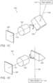
PCT/IB2016/057366 .FIG. 1A shows schematically a folded Tele camera disclosed therein and numbered100 from a first perspective view.FIG. 1B showscamera 100 from a second perspective view.Camera 100 includes alens 102 with a lensoptical axis 110, an optical path folding element (OPFE)104 and animage sensor 106. OPFE104 folds a first optical path which defines the point of view (POV)108 ofcamera 100 and which is substantially parallel to the X axis from an object, scene orpanoramic view section 114 into a second optical path along anaxis 110 substantially parallel to the Z axis.Image sensor 106 has a plane normal aligned with (parallel to)axis 110 and outputs an output image that may be processed by an image signal processor (ISP - not shown). In some embodiments, the ISP may be part ofimage sensor 106. Camera 100 is designed to rotate OPFE104 around axis110 (the Z axis) relative to the image sensor, a rotation indicated by anarrow 112. That is,camera 100 is a "scanning" Tele camera ("STC"). OPFE104 can rotate in an angle range as required by optical requirements (see below), in some cases by up to 180 degrees and in other cases by up to 360 degrees. Camera100 can scan a scene with its "native" Tele field of view ("N-FOVT"), so that it effectively covers a FOV of a scene which is larger than N-FOVT and which we call scanning Tele FOV ("S-FOVT"). S-FOVT is the FOV that includes all scene segments that can be captured with the STC in a plurality of STC images. For scanning a scene in 2 dimensions, OPFE104 must be rotated around two rotation axes. For example, N-FOVT = 10 - 20 deg and S-FOVT = 30 - 80 deg.FIG. 1C shows OPFE104 after rotation by 30 degrees andFIG. 1D shows OPFE104 after rotation by 180 degrees from the zero position. The 30 and 180 degree rotated positions are exemplary of a range of many rotation positions.- Images are acquired from a certain point of view (POV) of the camera. The POV is the direction defined by the unit vector of the vector that has the location of the camera aperture as starting point and an object point at the center of N-FOVT as end point. As an example, in spherical coordinates (r, θ, ϕ) defined according to ISO convention, the POV for a camera at r = 0 is defined by (1, θ, ϕ), with the polar angle θ and azimuthal angle ϕ defining the location of the object point at C-N-FOVT. In
FIGS. 1A and 1B , the OPFE is in a zero rotation position ("zero position"). With the OPFE in a zero position, an image acquired with the sensor (i.e. "produced" by camera100) has no POV aberrations. In spherical coordinates defined as see above, the zero rotation position is given by (1, 0, 0). When the POV changes, the image acquired by the sensor undergoes POV aberrations. Specifically, an image may be tilted (stretched to a trapeze shape) and/or rotated and/or scaled, see e.g.FIG. 2A and2B . US 2002/180759 A1 discloses a tele folded camera with a mirror that is rotated in order to take panoramic images,US 2013/286221 A1 shows a camera with a path folding element and is dealing with the correction of structures which are supposed to be upright but are not due to image distortions.- There is a need for and it would be advantageous to have a STC image without POV aberrations regardless of the POV.
- Considering the OPFE position, a method suggested herein uses a digital algorithm to correct the POV aberration to obtain an image without POV aberrations. After acquiring (capturing) an image and correcting it, it is suggested herein to crop a rectangular area from the corrected image, to display a cropped rectangular image on the screen or save the cropped rectangular image to a file. For each OPFE position, a pre-calculated geometric transformation (i.e. homography transform) is applied on the acquired image, resulting in a POV aberration-corrected image.
- Depending on the OPFE position after correcting the POV aberration, the original (uncorrected) image center will not coincide with the corrected image center. There may be for example five different cropping options (A, B, C, D, E), see
FIG. 3D . - The outcome of the cropping is a rectangular image with the same aspect ratio AR (i.e. height / width = 3/4) as the zero position, but with a smaller image area than for the zero-position image area. The size of the image area depends on the OPFE position. The corrected and cropped image is scaled to fit the display size or the saved image size.
- All images may be further cropped to have the same crop size (image area) for all OPFE positions. The maximal crop size that fits all OPFE positions can be calculated as the minimal size from the set of maximum sizes for every OPFE position.
- In various embodiments there are provided methods, comprising: providing a Tele folded camera that includes an OPFE and an image sensor; tilting the OPFE in one or more directions to direct the Tele folded camera towards a POV; capturing a Tele image or a stream of Tele images from the POV, the Tele image having a POV aberration; and digitally correcting the POV aberration.
- Is some embodiments, the POV may have a plurality of aberrations and the above and below apply to the correction of one, some, or all of the plurality of aberrations.
- In some embodiments, the correcting the POV aberration includes applying a geometric transformation to the captured Tele image to obtain a respective aberration-corrected image. In some exemplary embodiments, the geometric transformation uses calibration information captured during a camera calibration process.
- In some embodiments, a method further comprises cropping the aberration-corrected image to obtain an aberration-corrected cropped (ACC) image that has an ACC image center, an ACC image size and an ACC image width/height ratio.
- In some embodiments, a method further comprises scaling the ACC image to obtain an aberration-corrected cropped and scaled output image that has an output image center (OIC), an output image size and an output image width/height ratio. In some embodiments, the tilting of the OPFE and the capturing of a Tele image from the POV are repeated to obtain a plurality of Tele images captured at a plurality of POVs, and the OIC is selected such that a plurality of Tele images captured for all possible POVs cover a maximum rectangular area within a scene. In some embodiments, the tilting of the OPFE and the capturing of a Tele image from the POV are repeated to obtain a plurality of Tele images captured at a plurality of POVs, and the OIC is selected such that a plurality of Tele images captured for a particular plurality of POVs cover a maximum rectangular area within a scene.
- In various embodiments there are provided systems, comprising: a Wide camera with a Wide field of view FOVw; a Tele folded camera with a Tele field of view FOVT < FOVw and which includes an OPFE and an image sensor, the Tele camera having a scanning capability enabled by OPFE tilt in one or more directions to direct the Tele folded camera towards a POV of a scene and used to capture a Tele image or a stream of Tele images from the POV, the Tele image or stream of Tele images having a POV aberration; and a processor configured to digitally correct the POV aberration.
- In some embodiments, the POV aberration may be corrected using calibration data.
- In some embodiments, the calibration data may be stored in a non-volatile memory.
- In some embodiments, the calibration data include data on calibration between tilt positions of the OPFE in one or two directions and corresponding POVs.
- In some embodiments, the calibration data may include data on calibration between a Tele image and a Wide image.
- In some embodiments, the calibration data may include data on calibration between tilt positions of the OPFE in one or two directions and the position of FOVT within FOVw.
- In some embodiments, the processor configuration to digitally correct the POV aberration may include applying a configuration to apply a geometric transformation to the captured Tele image or stream of Tele images to obtain an aberration-corrected image.
- In some embodiments, the geometric transformation may be a homography transformation.
- In some embodiments, the geometric transformation may include a homography motion-based calculation using a stream of frames from the Wide camera.
- In some embodiments, the homography motion-based calculation may further use inertial measurement unit information.
- In some embodiments, the geometric transformation may be a non-affine transformation.
- In some embodiments, the image sensor has an image sensor center, an active sensor width and an active sensor height, and the OIC coincides with the image sensor center.
- In some embodiments, the OIC may be selected such that a largest possible rectangular crop image size for a particular output image width/height ratio is achieved.
- In some embodiments, the OIC may be located less than a distance of 10 x pixel size away from an ideal OIC.
- In some embodiments, the OIC may be located less than a distance of 10% of the active sensor width away from an ideal OIC.
- In some embodiments, the OIC may be located less than a distance of 10% of the active sensor height away from an ideal OIC.
- In some embodiments, the OIC may be selected such that an object-image magnification M of an object across different POVs does vary from a constant value by less than 10%
- In some embodiments, the OIC may be selected such that the output image covers a maximum area within a scene.
- In some embodiments, the OIC may be selected such that a plurality of Tele images captured for all possible POVs cover a maximum rectangular area within the scene.
- In some embodiments, the OIC may be selected such that a plurality of Tele images captured for a particular plurality of POVs cover a maximum rectangular area within the scene.
- In some embodiments, the OIC may be selected such that the output image shows a region of interest or object of interest in a visually appealing fashion.
- In various embodiments there are provided methods, comprising: providing a Tele folded camera that includes an OPFE and an image sensor; tilting the OPFE in one or more directions to direct the Tele folded camera towards a POVs of a calibration chart, each POV associated with a respective OPFE position; capturing a respective Tele image of the calibration chart at each POV, each Tele image having a respective POV aberration; analyzing the Tele image data for deriving calibration data between each POV with its respective POV aberration and the respective OPFE position; and using the calibration data to digitally correct the POV aberration.
- In some embodiments, the calibration chart may include location identifiers that allow to determine the POV for the given OPFE position from the respective Tele image.
- In some embodiments, the calibration chart may include angular identifiers that allow to determine the POV aberration for the given OPFE position from each Tele image.
- In some embodiments, the calibration chart may be a checkerboard chart.
- In some embodiments, the calibration data chart may represented by a bi-directional function that translates any OPFE position to a Tele POV and/or its respective POV aberrations and vice versa.
- In some embodiments, the bi-directional function chart may a polynomial.
- In some embodiments, the calibration data chart may represented by a bi-directional Look-Up-Table that translates any OPFE position to a Tele POV and/or its respective POV aberrations and vice versa.
- In some embodiments, the calibration data chart may represented by a Look-Up-Table comprising a plurality of OPFE positions with associated values for Tele POVs and/or its respective POV aberrations.
- In some embodiments, the plurality of OPFE positions may include more than five OPFE positions, more than 50 OPFE positions, or even more than 250 OPFE positions.
- In some embodiments, a method may further comprise providing a Wide camera with a field of view FOVw larger than a field of view FOVT of the Tele folded camera.
- In some embodiments, between the analyzing of the Tele image and the using of the calibration data, a method may further comprise: in a first additional step, with a Tele image POV positioned within a respective Wide image FOV at a respective OPFE position associated with the Tele image POV, capturing an additional Tele image of the calibration chart along with capturing a Wide image of the calibration chart, and in a second additional step, using the Tele and Wide image data for deriving calibration data between the respective OPFE position, the Tele POV within the respective Wide FOV and the Tele image's POV aberration with respect to the Wide image. In some such embodiments, the first and second additional steps may be performed simultaneously. In some such embodiments, all the steps may be performed by a same operator. In some such embodiments, the first four steps may be performed by a first operator, and the first and second additional steps may be performed by a second operator. In some such embodiments, the first four steps may be performed in a time frame of less than 10s, and the first and second additional steps are performed in a time frame of less than 10s. In some such embodiments, the first four steps may performed in a time frame of less than 5s and the first and second additional steps are performed in a time frame of less than 5s. In some such embodiments, the first additional step does not include any additional image capture, and the analysis and the deriving of the calibration data may include receiving external calibration data between the Tele folded camera and the Wide camera.
- Non-limiting examples of embodiments disclosed herein are described below with reference to figures attached hereto that are listed following this paragraph. The drawings and descriptions are meant to illuminate and clarify embodiments disclosed herein, and should not be considered limiting in any way. Like elements in different drawings may be indicated like numerals.
FIG. 1A shows schematically a known folded camera with an OPFE in zero position from one perspective view;FIG. 1B shows schematically the folded camera ofFIG. 1A from another perspective view;FIG. 1C shows schematically the camera ofFIG. 1A with the OPFE in a first non-zero position;FIG. 1D shows schematically the camera ofFIG. 1A with the OPFE in a second non-zero position;FIG. 2A shows different OPFE positions and respective FOVs in an object domain;FIG. 2B shows acquired images, corrected images and cropped images of respective objects at the three different OPFE positions;FIG. 2C shows the method for generating a Tele output image as described herein;FIG. 3A shows an FOV of the entire range of the OPFE scanning positions with an exemplary object;FIG. 3B shows details of the acquired image of the exemplary object inFIG. 3A ;FIG. 3C shows details of a corrected image of the acquired image inFIG. 3B ;FIG. 3D shows details of a cropped image of the corrected image inFIG. 3C ;FIG. 4 shows schematically an embodiment of an electronic device including multi-aperture cameras with at least one scanning Tele camera;FIG. 5 shows a method for a STC calibration process described herein;FIG. 6 shows an exemplarily calibration chart that may be used for the calibration method described inFIG 5 .FIG. 2A shows different OPFE positions and their respective N-FOVTs in an "object domain".FIG. 2B shows acquired images, corrected images and cropped images of respective objects at the three different (0, 1 and 2) OPFE positions shown inFIG. 2A . The object domain is defined as the appearance of a scene that is captured by an ideal camera having a sufficiently large FOV and not having any aberrations and distortions. That is, the object domain corresponds to the appearance of the scene as it may appear to a human observer. The object domain is differentiated from an "image domain", which is defined as the appearance of the scene as captured by a STC such ascamera 100.- In
FIGS. 2A-B ,202-i (i = 0, 1, 2) represent S-FOVTs,204-i represent objects,206-i represent image frames,208-i represent images of objects204-i, 210-i represent image data boundaries and212-i represent rectangular crops of image frames. Box 200 represents the smallest rectangular FOV that includes S-FOVT, i.e. all the image data from all POVs that can be reached with a STC in the object domain. The N-FOVTs for three different OPFE positions (0, 1 and 2) are represented by202-0, 202-1 and202-2. Each OPFE position corresponds to a different POV. The N-FOVT for an OPFE "zero position"202-0 is defined as an N-FOVT that produces an image of an object or scene without POV aberrations, i.e. (besides a scaling factor and assuming no camera aberrations and distortions) at zero position an object in the object domain is identical to the object image in the image domain. As shown, the N-FOVT at any other position (e.g.202-1 and202-2) is not a horizontal rectangle (with respect to202-0), but an arbitrary tetragon. The same rectangular object is represented by204-0, 204-1 and204-2 in, respectively, N-FOVTs202-0, 202-1 and202-2.- In an example, the OPFE is positioned at a scanning position 1 (
FIG. 2A ) with N-FOVT202-1 that includes object204-1 and represents a POV of the STC. An image frame206-1 (FIG. 2B ) is captured (acquired) atposition 1. In the captured image, object204-1 is represented by captured object image208-1 (FIG. 2B ). A geometric transformation is applied on frame206-1 to obtain a corrected image frame206'-1. The geometric transformation is related to the rotation angle of the OPFE under which the respective image was captured. Inside corrected image frame206'-1, one can see the corrected image208'-1 of image208-1. 210'-1 marks the boundary of image data present in corrected image frame206'-1, and212-1 is a possible rectangular crop comprising an image segment of210'-1. Rectangular crop212-1 may have the same aspect ratio AR (i.e. a ratio of horizontal width and vertical height) as AR ofimage sensor 106. In other examples, rectangular crop212-1 may have a same aspect ratio as the aspect ratio used for outputting a zero position image such as206"-0. Corrected image206'-1 is then cropped to obtain a corrected croppedimage 206"-1. - In
FIG. 2B in the acquired image row,206-0, 206-1 and206-2 are original raw image captures (frames) acquired at, respectively, OPFE positions 0, 1 and 2.208-0, 208-1 and208-2 are captured images of, respectively, objects204-0, 204-1 and204-2. In the corrected image row,206'-0, 206'-1 and206'-2 represent corrected (also referred to as "rectified" or "aberration-corrected") image frames that underwent image rectification.208'-0, 208'-1 and208'-2 represent captured object images208-0, 208-1 and208-2 of objects204-0, 204-1 and204-2 after image rectification, i.e. they represent "corrected images" (or "rectified images") of the objects. The image data present in corrected image206'-1 has a boundary210'-1 and the image data in corrected image206'-2 has a boundary210'-2. The dotted area between206'-1 and210'-1, and between206'-2 and210'-2 has no valid image data to be shown on screen or saved to disk (i.e. the area includes only empty pixels).212-1 and212-2 are possible rectangular crops comprising image segments of210'-1 and210'-2 respectively.212-1 and212-2 may have a specific AR. In the cropped image row,206"-0, 206"-1 and206"-2 are aberration-corrected cropped ("ACC") images comprising image data of206'-0, 206'-1 and206'-2, i.e. they comprise corrected image data of206-0, 206-1 and206-2. In some embodiments, after cropping the images are scaled. Inimages 206"-0, 206"-1 and206"-2,areas 208"-0, 208"-1 and208"-2 represent the image data of objects204-0, 204-1 and204-2 which underwent rectification, cropping and scaling. Theimages 206"-1 and206"-2 are generated by cropping images206'-1 and206'-2 along the boundaries212-1 and212-2 respectively.Image 206"-0 did not undergo cropping, i.e. all image data of206'-0 is present also in206"-0. Note that since position '0' was defined as having no POV aberrations, the correction algorithm will have no effect on the acquired image (i.e.206-0, 206'-0 and206"-0 will be identical). In other examples,206-0, 206'-0 and206"-0 may not be of equal size, but206'-0 and/or206"-0 may differ in size from206-0 by a certain crop factor. The same applies for object images208-0, 208'-0 and208"-0. FIG. 2C shows schematically an exemplary method for generating a Tele output image disclosed herein. In afirst step 252, a command triggered by a human user or a program directs N-FOVT to a region of interest (ROI) within a scene by scanning. The scanning may be performed by rotating an OPFE. The FOV scanning by OPFE rotation is not performed instantaneously, but requires some settling time, which may be for example about 1-30 ms for scanning 2-5 degrees and about 15-100 ms for scanning 10-25 degrees. After the settling time, an STC image (such as images206-0, 206-1 and206-2 inFIG. 2B ) is captured instep 254. Instep 256, the STC image is rectified. In a first rectification sub-step (called "geometrical transformation sub-step"), a geometric transformation (such as a homography transformation, an affine transformation or a non-affine transformation) is performed, with results as shown inFIG. 2B . In the following and as an example, "homography transformation" is used to represent any meaningful geometric transformation. The homography transformation corrects for the aberrations associated with any particular POV and is thus a function of the POV. A second rectification sub-step ("interpolation sub-step") may be performed, which is detailed below.- A corrected (or rectified, or aberration-corrected) image is thus obtained. Calibration data between an OPFE position and the corresponding POV may be used to select the homography transformation corresponding to the particular POV. In some embodiments, the geometric transformation may include corrections known in the art such as e.g. distortion correction and color correction. In
step 258, the corrected image is cropped as depicted inFIG. 2B . Instep 260, the cropped image is scaled. A cropped and scaled output image is output instep 262. The output image may be displayed on an electronic device such as device400 (FIG. 4 ) and/or stored in a memory such as memory450 (FIG. 4 ) or any other memory of the device. - The cropping in
step 258 may be done according to different crop selection criteria. Some crop selection criteria may aim for a particular size of the cropped image. Other crop selection criteria may enable a particular input image coordinate to be transferred to a particular image coordinate of the cropped image. In the following, "crop selection" criteria may be referred to simply as "crop criteria". - Crop criteria that aim for a particular size of cropped images may be as follows: in one criterion (crop criterion 1), the image may be cropped so that a resulting image is a rectangular image. In another criterion (crop criterion 2), the resulting image may be a square. Here and in the following, the image size and shape are defined by the number and distribution of the image pixels, so that size and shape do not depend on the actual mode the image is displayed. As an example, a rectangular image hasm rows (image height), wherein each row includesn values (image width). A square image hasm rows withm values each. A first rectangular image havingm1 rows withn1 values each is larger than a second rectangular image havingm2 rows andn2 values ifm1 xn1 >m2 xn2 is satisfied.
- In yet another criterion (crop criterion 3), the image is cropped so that a largest rectangular image having a particular AR for the particular POV is obtained. Examples for this criterion are the crop options "D" and "E" shown in
FIG. 3D . The AR refers to the width/height ratio of an image. An AR may e.g. be 4:3, 3:2 or 16:9. In yet another criterion (crop criterion 4), the image captured at a first POV is cropped so that the resulting image has the same AR and size as an image captured at a second POV. The second POV is the POV that leads to the smallest image obtained by cropping a largest rectangular image having a particular AR for the second POV.Crop criterion 4 ensures that cropped images at all possible POVs have identical AR and shape. In yet another criterion (crop criterion 5), the image is cropped so that all output images generated from STC images captured instep 254 from the entire S-FOVT cover a largest area of a rectangular FOV in the object domain. This cropping criterion ensures that the area of a rectangular FOV in the object domain such as200 is covered maximally by S-FOVT. In yet another criterion (crop criterion 6), the image is cropped rectangularly so that an identical object-to-image magnification is obtained for the entire S-FOVT. In general, the object images of images captured instep 254 are smaller for larger POVs. In some embodiments, the condition of "identical magnification" may be satisfied if the magnifications obtained for all POVs vary from a constant value by < 10%. In other examples, the condition of "identical magnification" may be satisfied if the magnifications obtained for all POVs vary by < 5% or by <15%. - Crop criteria that map particular input image coordinates to particular image coordinates of the cropped image are presented next. In general, and by applying a particular crop selection criterion, any arbitrary object image point of the image captured in step254 (the "input image") can be defined as the image center of the image output in
step 262. In a crop criterion 7, the image may be cropped rectangularly so that the image center of the cropped image contains image data identical with that of the input image center for a particular POV. An image center may be defined as the center pixel and the surrounding pixels that lie within a radius of e.g. 10 times the pixel size. In some embodiments, the image center may be defined as the center pixel plus surrounding pixels that lie within a radius of e.g. 5 or 30 times the pixel size. - In a crop criterion 8, the image may be cropped rectangularly so that the cropped image center contains image data identical with that of an input image center, with the cropped image additionally fulfilling the condition that any two images that are captured at arbitrary first and second POVs are cropped so that the resulting images have the same AR and size. In yet other examples, crop criterion 8 may additionally fulfill the condition that the cropped images are of maximal size (crop criterion 9). In yet other examples, an image may be cropped so that a ROI or an object of interest (OOI) is displayed on the image output in step264 in a visually appealing fashion (crop criterion 10). This criterion may support aesthetic image cropping, e.g. as described byWang et al in the article "A deep network solution for attention and aesthetics aware photo cropping", May 2018, IEEE Transactions on Pattern Analysis and Machine Intelligence. Applications of aesthetic image cropping are also described in the co-owned PCT Patent Application No.
PCT/IB2020-061330 . In yet other examples, an image may be cropped according to the needs of further processing steps, e.g. the image may be cropped so that only a particular segment of the FOV in the object domain is included (crop criterion 11). A possible further processing may e.g. be the generation of a super image, i.e. of an output image that is composed of the image data of a plurality of input images. The generation of a super-image is described in co-owned PCT Patent Application No.PCT/IB2021-054070 . Another possible further processing may be the generation of a panorama image as known in the art. - The scaling in
step 260 may be performed according to different scaling selection criteria. In some embodiments, scaling may be performed so that images captured under different POVs instep 254 and output in step262 (the "output image") have identical size and AR (scale criterion 1). In other examples, scaling may be performed so that the pixel density per object image area in the output image is identical with the pixel density per area in the object domain present in the image captured in step254 (scale criterion 2). In yet other examples, scaling may be performed so that the image size fits the requirements of a program that performs further processing on the image data (scale criterion 3). - Steps252-262 outlined above may be performed sequentially, i.e. one after the other.
- In some STC image rectification embodiments,
step 256 may be performed as follows: let (xini, yinj) be the values of some arbitrary image coordinates (i, j) of an input image (captured in step254) and let (xoutm, youtn) be the values of some arbitrary image coordinates (m, n) of an output image (of step256). In the geometrical transformation sub-step, a homography transformation may be (xout, yout) = fH(xin, yin) with H being a 3x3 homography transformation matrix known in the art. The homography transformation can be inversed by using fH-1 = fH-1. A crop transformation (xout, yout) = Crop(xin, yin) may be (xoutm, youtn) = (xmi - crop-start_xi, yinj - crop-start_yj) for assigning each coordinate of the input image a coordinate in the output image wherein only coordinates with values > 0 are used for the output image. Vector (crop-start_xi, crop-start_yj) defines size and shape of the cropped image. An inverse crop transformation Crop-1 is defined by (xinm, yinn) = (xout, + crop-start_xi, youtj - crop-start_yj). A scale transformation (xout, yout) = Scale(xin, yin) may be (xout, yout) = (sx·xin, sy·yin) with scaling factors sx and sy in x and y direction respectively. An inverse scale transformation Scale-1 is defined by (xin, yin) = (sx-1·xout, sy-1·yout). A transfer function T is defined by applying homography, crop and scale sequentially, i.e. T is defined by (xout, yout) = Scale(Crop(fH(xin, yin))) and (xout, yout) = T(xin, yin). - In the interpolation sub-step, one may sequentially interpolate all values of output image (xout, yout) directly from the input image via transfer function T. For example, one may start with calculating values (xoutm, youtn) at an arbitrary starting point having coordinates (m, n) of the output image. For this, one calculates coordinates (m', n') of input image (xin, yin) that are to be included for calculating values (xoutm, youtn) at the particular coordinates (m, n) of the output image. Coordinates (m', n') in the input image may be obtained by applying an inverse transfer function T-1 to all output coordinates (m, n), i.e. T-1(xoutm, youtn) or fH-1(crop-1(scale-1(xoutm, youtn))) for all (m, n). In general, T-1 may not map each coordinate (m, n) on one coordinate (m', n'), but map each coordinate on a segment of neighboring coordinates (m', n'). For calculating the values (xoutm, youtn), the entire segment or parts of the segment of neighboring coordinates (m', n') may be taken into account. For obtaining values (xoutm, youtn) of the output image at coordinates (m, n), in a first step a re-sampling function R as known in the art may be evaluated for all neighboring coordinates (m',n') according to T(xout'm, yout'n) = Resample (Tin,xinm', yinn'). The re-sampling may be performed by methods known in the art such as nearest neighbor, bi-linear, or bi-cubic.
- After values (xoutm, youtn) are determined, one may perform the steps above for calculating the values (xouto, youtp) at additional coordinates (o, p), etc. This is repeated until all values (xout, yout) of the output image are obtained. In various embodiments, the calculation as described above is performed for a plurality of output coordinates or even for all output coordinates in parallel. In some STC image rectification embodiments, the calculations described here may be performed by a CPU (Central Processing Unit). In other STC image rectification embodiments and for faster image processing, the calculations described here may be performed by a GPU (Graphics Processing Unit). The STC image rectification may be performed in different color domains, e.g. RGB, YUV, YUV420 and further color domains known in the art.
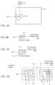
FIG. 3A shows S-FOV T300 in the object domain.302 represents a N-FOVT corresponding to a particular OPFE position within300. 304 represents the object point in the scene whose image point is located at the center of the image sensor.306 represents an arbitrary selected particular object point in the scene that is included in N-FOV T302.FIG. 3B shows an acquiredTele image 310 having a center304' and including an image point306' ofobject point 306.FIG. 3C shows a correctedimage 312 generated by applying the geometric transformation described above toimage 310. 314 is the boundary of the image data in the corrected image, i.e. outside of the boundary (dotted area) there is no image data available.304" and306" are the locations of image points304' and306' respectively in the corrected image.FIG. 3D shows exemplarily different options for rectangularly cropping correctedimage 312 shown inFIG. 3C and generating an output image as described herein. One can see that the image data that is located at the output image center (OIC) depends on the selected cropping criteria. In the examples marked "D" and "C", crop selection criteria are selected so that particular image point306' is located at the OIC. Cropping option "D" is selected so that two criteria are fulfilled: (i) "particular image point306' is located at the OIC" and (ii) "the largest rectangular image for the given POV is achieved". Cropping option "C" is selected so that the criterion "particular image point306' is located at the OIC" is fulfilled. Additional crop selection criteria are depicted in the examples marked "A", "B" and "E". Cropping option "A" is selected so that the criterion "image center304' is located at the OIC" is fulfilled. Cropping option "B" is selected so that two criteria are fulfilled: (i) "image center304' is located at the OIC" and (ii) "the largest rectangular image for the given POV is achieved". Cropping option "E" is selected so that for the output image the criterion "the largest rectangular image for the given POV is achieved" is fulfilled. In other examples (not shown), a cropping option may be selected so that two criteria are fulfilled: (i) "image center304' is located at the OIC" and (ii) "the largest rectangular image for all possible POVs is achieved". It may not always be possible or beneficial to locate the OIC exactly at a particular image position ("ideal OIC") such as e.g. the image center, but in proximity of the ideal OIC. Proximity of the ideal OIC may be expressed as a percentage of the image sensor size (e.g. OIC may be located < 10% of image sensor width from the ideal OIC) or as a distance in pixels (e.g. OIC may be located less than a distance of 10 x pixel size away from the ideal OIC).- In yet other examples (not shown), a cropping option may be selected so that that the criterion "the largest rectangular image for all possible POVs is achieved" is fulfilled. In yet other examples (not shown), a cropping option may be selected so that that the criterion "the largest rectangular image for a particular plurality of POVs is achieved" is fulfilled. The particular plurality of POVs may cover all possible POVs or a subset thereof.
FIG. 4 shows schematically an embodiment of a mobile electronic device ("electronic device") numbered400 and including multi-aperture cameras with at least one STC.Electronic device 400 may e.g. be a smartphone, a tablet, a laptop, etc..Electronic device 400 comprises afirst STC module 410 that includes anOPFE 412 for FOV scanning, and aTele lens module 418 that forms a Tele image recorded by afirst image sensor 416.Image sensor 416 has an active sensor area defined by an active sensor width and an active sensor height which performs the actual light harvesting, and an inactive area that does not perform light harvesting. ATele lens actuator 422 may movelens module 418 for focusing and/or optical image stabilization (OIS).Electronic device 400 may further comprise an application processor (AP)440 that includes aFOV scanner 442, amotion estimator 444 and animage generator 446.STC 410 may have an effective focal length ("EFL") of EFL=5mm-50mm. A sensor diagonal ("SD") ofimage sensor 416 may be SD=3mm-15mm.- Calibration data may be stored in a
first memory 424, e.g. in an EEPROM (electrically erasable programmable read only memory), in asecond memory 438, or in athird memory 450, e.g. in a NVM (non-volatile memory). Calibration data may include STC calibration data and DC calibration data.Electronic device 400 further comprises a Wide ("W") (or Ultra-Wide, "UW")camera module 430 with a FOVW, FOVUW> N-FOVT that includes asecond lens module 434 that forms an image recorded by asecond image sensor 432. Asecond lens actuator 436 may movelens module 434 for focusing and/or OIS. - In use, a processing unit such as
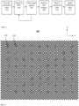
AP 440 may receive respective first and second image data fromcamera modules camera modules FOV scanner 442 may receive commands from a human user or a program for directing the N-FOVT to particular POVs in a scene. In some embodiments, the commands may include a single request for directing N-FOVT to one particular POV. In other examples, the commands may include a series of requests e.g. for serially directing N-FOVT to a plurality of particular POVs.FOV scanner 442 may be configured to calculate a scanning order given the requested particular POVs.FOV scanner 442 may be configured to supply control signals toOPFE actuator 414, which may, in response to the control signals, rotateOPFE 412 for scanning N-FOVT. In some embodiments,FOV scanner 442 may additionally supply control signals toOPFE actuator 414 for actuatingOPFE 412 for OIS. Electronic device 400 further comprises an inertial measurement unit (IMU, or "Gyro")460 that may supply information on the motion of400.Motion estimator 444 may use data fromIMU 460, e.g. for estimating hand motion caused by a human user. In some embodiments,motion estimator 444 may use additional data. For example, image data fromcamera 410 and/or fromcamera 430 may be used to estimate an "optical flow" from a plurality of images as known in the art.Motion estimator 444 may use data fromIMU 460 and may use as well optical flow data for estimating motion of400 with higher accuracy. The information on motion of400 may be used for OIS or for the homography transformation described above. In other embodiments, only optical flow data estimated from image data ofcamera 410 and/orcamera 430 may be used for estimating motion of400.Image generator 446 may be configured to generate images and image streams respectively as e.g. described inFIG. 2C . In some embodiments,image generator 446 may be configured to use only first image data fromcamera 430. In other embodiments,image generator 446 may use image data fromcamera 410 and/orcamera 430.FIG. 5 shows a method for a STC calibration process described herein. The calibration process allows to derive calibration data for a single scanning Tele camera ("STC calibration") or for a dual-camera ("DC") including a STC and a Wide camera having a FOVW>N-FOVT ("DC calibration"). Goal of the calibration process is to connect between three parameters for all possible POVs: a specific OPFE position which is defined by a position sensor value pair, the POV associated with this specific OPFE position as well as the POV aberrations associated with this specific POV.- In a first example (calibration example 1 or "CE1"), the calibration process refers to a STC that scans in 2 dimensions by rotating an OPFE along two axes, wherein the amplitude of the rotation is measured by two or more position sensors (e.g. Hall sensors), a first and a second position sensor P1 and P2 respectively. The STC's POV is measured by the value pair p1 and p2 of P1 and P2 respectively. In a
first step 502, a calibration chart ("CC") is provided. A suitable CC includes location identifiers (such aslocation identifiers FIG. 6 ) which allow to determine the location on the chart. When capturing a suitable CC at a given distance with a STC, at least one location identifier is present in N-FOVT for all POVs in S-FOVT. By means of the location identifier, the STC's POV with respect to the CC can be determined. The location identifiers may e.g. be symbols encoding location information, spread in sufficiently high frequency all over the checkerboard. Additionally, a suitable CC includes angular identifiers that allow to determine the relative angular tilt and rotation between the CC and a STC's image of the CC. The angular identifiers may e.g. be lines present in a checkerboard. An example of a suitable CC is shown inFIG. 6 . The size of the CC and the distance between the STC and the CC is to be selected so that the entire S-FOVT is included in the FOV covered by the CC. - In CE1, a list of N specific value pairs (p1, p2) may be defined for a specific STC design. In some embodiments, the list may include N=10 value pairs (p1, p2)1, ..., (p1, p2)10. In other embodiments, the list may include N=10 - 20 or even more value pairs. According to a first criterion for value pair selection, the value pairs may be selected so that the STC must capture a minimum number of different POVs in the calibration process (or, in other words, a minimum number of repetitions of
steps - For a second example ("CE2") for DC calibration, in
step 502 another CC may be required, wherein the CC may or may not be a checkerboard. The STC of CE2 fulfills the same attributes as for CE1. Also in CE2, a list of N specific position sensor value pairs (p1, p2), each value pair associated with a specific OPFE position, may be defined for a specific STC design. In some embodiments, the list may include N=200 value pairs (p1, p2)1, ..., (p1, p2)200. In other embodiments, the list may include N=100 - 300 or even more value pairs. - By tilting the OPFE to a specific OPFE position, in CE1 and CE2 e.g. defined by (p1, p2)1, in
step 504 the STC is directed to a (yet unknown) POV on the CC. - In
step 506, one or more STC images are captured. For DC calibration and for CE2, a second sub-step ofstep 506 is required, where STC images are captured along W images captured by the Wide camera. Capturing STC images along W images means here that the images are captured at a same dual-camera position and orientation. In general, the capture may be simultaneous, but this is not mandatory. - In some embodiments, the capturing of the STC images along the Wide images may be performed together and in one single step, e.g. by a same operator.
- In other examples, the two steps may be performed separately and e.g. by different operators. For example and for calibrating a STC with respect to a first CC, a first operator may capture one or more STC images at a specific OPFE position. The STC which is calibrated with respect to the first CC may be included by a second operator into a dual-camera which is used for capturing a second CC (which may be or may be not identical to the first CC) with the STC at a specific OPFE position along with one or more W images for calibrating the STC with respect to the W camera of the dual-camera.
Steps steps step 506 does not include capturing additional STC and W images, but includes receiving external calibration data between the STC and the Wide camera. - In
step 508, the STC images are analyzed. Aim is to assign a POV and a respective POV aberration to the specific OPFE (or value pairs) position ofstep 504. The analysis includes to use the CC's location identifiers that appear in a STC image to determine the POV from which it was captured, as well as to use the CC's angular identifiers along with GT images to determine the POV aberrations. - For CE1, the analysis includes to use the CC's location identifiers that appear in a STC image to determine the POV from which it was captured, as well as to use the CC's angular identifiers along with ground truth images to determine the POV aberrations.
- In a first sub-step of CE1, a specific POVi is assigned to the value pair (p1, p2)i.
- In a second sub-step of CE1, the STC image is compared to a ground truth image of the CC at the respective POV. In this comparison it is determined which image transformation parameters transform the STC image into the CC's ground truth image. In some embodiments, three image transformation parameters may be used. For DC and CE2, POVs and respective POV aberrations are determined by comparing the STC images and the Wide images captured in
step 506. - In
step 508 of CE1, the first and the second sub-step are performed for all value pairs (p1,p2)1, ..., (p1,p2)N, so that to each value pair (p1,p2)i a specific POVi and image transformation parameters are assigned. - In
step 510, from the analysis instep 508, calibration data is derived. In some embodiments, the calibration data is represented by a bi-directional data polynomial. In other examples, the calibration data is represented by a bi-directional Look-Up-Table (LUT) polynomial. In all examples, STC calibration data includes a function that can be used to translate any OPFE position to a STC image's POV aberrations with respect to a checkerboard and/or STC's POV. DC calibration data can be used to translate any OPFE position to a STC image's POV aberrations with respect to the W camera and/or STC's POV within FOVw. Vice versa, any POV aberration of an STC image with respect to a W camera's image can be translated into a STC POV within FOVw and/or to an OPFE position (thus "bi-directional"). In yet other examples, STC calibration data is represented by a LUT which comprises a multitude of OPFE positions with associated values for STC images' POV aberrations with respect to the CC and/or STC's POVs. DC calibration data is represented by a LUT which comprises a multitude of OPFE positions with associated values for STC images' rotation angles with respect to the Wide camera's images and/or Tele POVs within FOVw. For CE1, a function is determined which approximates the relation between all the value pairs (p1, p2)1, ..., (p1,p2)N and their assigned specific POVs, POV1, ..., POVN, as well as their assigned image transformation parameters. This function is generalized, meaning that it is used for bi-directionally translating between all possible OPFE position value pairs, their POVs and image transformation parameters for image rectification. According to a second criterion for value pair selection, the value pairs may be selected so that the generalization of the function leads to a minimum aggregated error ("AE"). "AE", which is to be minimized, refers here to an error function that depends on the deviation of the STC images that underwent the POV correction from their respective ground truth images for all possible POVs (or a number of POVs that is sufficiently large to approximate statistically all possible POVs). In some embodiments, some compromise between fulfilling the first or the second criterion for value pair selection is made. - For CE2, the calibration data derived is included in a LUT. The LUT includes the N OPFE positions (value pairs), the POV associated with each value pair as well as its respective POV aberration. This implies that not for all possible OPFE positions there is explicit calibration data. So for rectifying a STC image with CE2 at an OPFE position which is not included in the LUT, one may approximate a POV and its POV aberrations. In some embodiments for approximation, one may use the calibration values which are associated with one OPFE position which is, from all the N OPFE positions, located closest to the current OPFE position. Closest may be defined here by a distance metrics known in the art, e.g. a quadratic distance of the respective value pairs (sqrt((p1-p1c)2+(p2-p2c)2)) may be smallest, where p1, p2 is the current OPFE position, and p1c, p2c are values included in the LUT. In other examples for approximation, one may use a weighted average of a plurality of calibration values which are associated with a plurality of OPFE positions which are, from all the N OPFE positions, located closest to the current OPFE position.
- In
step 512, the calibration data are applied to the STC images for correcting POV aberrations. FIG. 6 shows anexemplarily CC 600 that may be used for the calibration method described inFIG 5 .CC 600 includes 72 location identifiers, which are distributed in rows of 9 (oriented parallel x) and 8 columns (oriented parallel y). Exemplarily, the two first location identifiers of the first row are marked602 and604 respectively. A location identifier is located at a defined distance from a CC reference point, e.g. the upper left corner of CC. For calibrating withCC 600 at different camera-CC distances, one may adapt the size ofCC 600 so that at least one location identifier is present in N-FOVT for all POVs in S-FOVT.CC 600 includes additionally angular identifiers, which in this example are represented by the vertical and horizontal lines of the checkerboard.- While this disclosure has been described in terms of certain embodiments and generally associated methods, alterations and permutations of the embodiments and methods will be apparent to those skilled in the art. The disclosure is to be understood as not limited by the specific embodiments described herein, but only by the scope of the appended claims.
- Unless otherwise stated, the use of the expression "and/or" between the last two members of a list of options for selection indicates that a selection of one or more of the listed options is appropriate and may be made.
- It should be understood that where the claims or specification refer to "a" or "an" element, such reference is not to be construed as there being only one of that element.
Claims (15)
- A method comprising:a) providing a Tele folded camera (100) that includes an optical path folding element (OPFE) (104) and an image sensor (106);
characterized in further comprisingb) tilting the OPFE (104) in one or more directions to perform optical image stabilization (OIS);c) while performing OIS, capturing a stream of Tele images, wherein each Tele image has a respective point of view (POV) aberration; andd) digitally correcting the respective POV aberration. - The method of claim 1, wherein the correcting the respective POV aberration depends on a tilt position of the OPFE (104).
- The method of claim 1, wherein the correcting the respective POV aberration depends on calibration data.
- The method of claim 1, wherein data from an inertial measurement unit and/or image data are used for calculating OIS control signals.
- The method of claim 1, wherein the respective POV aberration represents a rotation of a Tele image.
- The method of claim 1, wherein the respective POV aberration represents a stretching to a trapeze shape of a Tele image.
- The method of claim 1, wherein the OPFE (104) is tilted in two directions to perform OIS.
- The method of claim 1, wherein the Tele folded camera has a scanning Tele field-of-view (S-FOVT) which is scanned by tilting the OPFE (104), the S-FOVT including a center POV and a plurality of non-center POVs, and wherein the Tele folded camera can be directed towards all POVs within S-FOVT to perform the OIS, wherein, for example, the respective POV aberration is caused by tilting the OPFE to the non-center POV.
- The method of claim 1, wherein the OPFE (104) is a prism.
- The method of claim 1, wherein the correcting the respective POV aberration includes applying a geometric transformation to the captured Tele image having the respective POV aberration to obtain a respective aberration-corrected image.
- The method of claim 10, wherein the geometric transformation uses calibration data captured during a camera calibration process.
- The method of claim 10, wherein the geometric transformation is a homography transformation.
- The method of claim 1, further comprising cropping the aberration-corrected image to obtain a respective aberration-corrected cropped (ACC) image that has an ACC image center, an ACC image size and an ACC image width/height ratio.
- The method of claim 13, further comprising scaling the ACC image to obtain a respective aberration-corrected cropped and scaled output image that has an output image center (OIC), an output image size and an output image width/height ratio.
- The method of any of the claims 1-14, wherein the method is used in a smartphone.
Priority Applications (1)
| Application Number | Priority Date | Filing Date | Title |
|---|---|---|---|
| EP25155993.6AEP4528372A3 (en) | 2020-07-15 | 2021-07-13 | Point of view aberrations correction in a scanning folded camera |
Applications Claiming Priority (3)
| Application Number | Priority Date | Filing Date | Title |
|---|---|---|---|
| US202063051993P | 2020-07-15 | 2020-07-15 | |
| PCT/IB2021/056311WO2022013753A1 (en) | 2020-07-15 | 2021-07-13 | Point of view aberrations correction in a scanning folded camera |
| EP21843329.0AEP4045960B1 (en) | 2020-07-15 | 2021-07-13 | Point of view aberrations correction in a scanning folded camera |
Related Parent Applications (2)
| Application Number | Title | Priority Date | Filing Date |
|---|---|---|---|
| EP21843329.0ADivisionEP4045960B1 (en) | 2020-07-15 | 2021-07-13 | Point of view aberrations correction in a scanning folded camera |
| EP21843329.0ADivision-IntoEP4045960B1 (en) | 2020-07-15 | 2021-07-13 | Point of view aberrations correction in a scanning folded camera |
Related Child Applications (2)
| Application Number | Title | Priority Date | Filing Date |
|---|---|---|---|
| EP25155993.6ADivisionEP4528372A3 (en) | 2020-07-15 | 2021-07-13 | Point of view aberrations correction in a scanning folded camera |
| EP25155993.6ADivision-IntoEP4528372A3 (en) | 2020-07-15 | 2021-07-13 | Point of view aberrations correction in a scanning folded camera |
Publications (3)
| Publication Number | Publication Date |
|---|---|
| EP4202521A1 EP4202521A1 (en) | 2023-06-28 |
| EP4202521B1true EP4202521B1 (en) | 2025-03-19 |
| EP4202521C0 EP4202521C0 (en) | 2025-03-19 |
Family
ID=79555154
Family Applications (3)
| Application Number | Title | Priority Date | Filing Date |
|---|---|---|---|
| EP23157770.1AActiveEP4202521B1 (en) | 2020-07-15 | 2021-07-13 | Point of view aberrations correction in a scanning folded camera |
| EP21843329.0AActiveEP4045960B1 (en) | 2020-07-15 | 2021-07-13 | Point of view aberrations correction in a scanning folded camera |
| EP25155993.6APendingEP4528372A3 (en) | 2020-07-15 | 2021-07-13 | Point of view aberrations correction in a scanning folded camera |
Family Applications After (2)
| Application Number | Title | Priority Date | Filing Date |
|---|---|---|---|
| EP21843329.0AActiveEP4045960B1 (en) | 2020-07-15 | 2021-07-13 | Point of view aberrations correction in a scanning folded camera |
| EP25155993.6APendingEP4528372A3 (en) | 2020-07-15 | 2021-07-13 | Point of view aberrations correction in a scanning folded camera |
Country Status (5)
| Country | Link |
|---|---|
| US (3) | US11910089B2 (en) |
| EP (3) | EP4202521B1 (en) |
| KR (3) | KR102862382B1 (en) |
| CN (6) | CN116125660A (en) |
| WO (1) | WO2022013753A1 (en) |
Families Citing this family (3)
| Publication number | Priority date | Publication date | Assignee | Title |
|---|---|---|---|---|
| KR102862382B1 (en)* | 2020-07-15 | 2025-09-18 | 코어포토닉스 리미티드 | Point of view aberrations correction in a scanning folded camera |
| US20230023158A1 (en)* | 2021-07-16 | 2023-01-26 | Samsung Electro-Mechanics Co., Ltd. | Image sensor, camera module, and electronic device including the same |
| US12250449B2 (en)* | 2023-02-28 | 2025-03-11 | Zebra Technologies Corporation | Systems and methods for rapid camera illumination tuning |
Citations (1)
| Publication number | Priority date | Publication date | Assignee | Title |
|---|---|---|---|---|
| US20020180759A1 (en)* | 1999-05-12 | 2002-12-05 | Imove Inc. | Camera system with both a wide angle view and a high resolution view |
Family Cites Families (448)
| Publication number | Priority date | Publication date | Assignee | Title |
|---|---|---|---|---|
| US3085354A (en) | 1957-01-31 | 1963-04-16 | Westinghouse Electric Corp | Multi-gimbal flight simulator |
| US3584513A (en) | 1969-01-06 | 1971-06-15 | Singer General Precision | Self-calibrating system for navigational instruments |
| US3941001A (en) | 1973-11-09 | 1976-03-02 | Lear Siegler, Inc. | Gimbal control mechanism |
| US4199785A (en) | 1979-01-05 | 1980-04-22 | Honeywell Inc. | Electronic zoom system |
| JPS59191146A (en) | 1983-04-13 | 1984-10-30 | Hitachi Ltd | Optical scanner |
| US5099263A (en) | 1984-11-10 | 1992-03-24 | Minolta Camera Kabushiki Kaisha | Variable focal length camera |
| JPH0690350B2 (en) | 1986-12-15 | 1994-11-14 | 富士写真光機株式会社 | camera |
| DE58902538D1 (en) | 1988-05-19 | 1992-12-03 | Siemens Ag | METHOD FOR OBSERVING A SCENE AND DEVICE FOR IMPLEMENTING THE METHOD. |
| DE3927334C1 (en) | 1989-08-18 | 1991-01-10 | Messerschmitt-Boelkow-Blohm Gmbh, 8012 Ottobrunn, De | |
| JP2703105B2 (en) | 1989-10-20 | 1998-01-26 | 富士写真フイルム株式会社 | Image stabilization device |
| US5032917A (en) | 1990-03-12 | 1991-07-16 | Rca Licensing Corporation | Video signal blending apparatus |
| JPH0443773A (en) | 1990-06-11 | 1992-02-13 | Matsushita Electric Ind Co Ltd | Arithmetic circuit |
| US5041852A (en) | 1990-10-18 | 1991-08-20 | Fjui Photo Film Co., Ltd. | Camera shake correction system |
| JP3261152B2 (en) | 1991-03-13 | 2002-02-25 | シャープ株式会社 | Imaging device having a plurality of optical systems |
| US5394520A (en) | 1991-09-26 | 1995-02-28 | Hughes Aircraft Company | Imaging apparatus for providing a composite digital representation of a scene within a field of regard |
| US5657402A (en) | 1991-11-01 | 1997-08-12 | Massachusetts Institute Of Technology | Method of creating a high resolution still image using a plurality of images and apparatus for practice of the method |
| JP3103166B2 (en) | 1991-11-26 | 2000-10-23 | 富士写真光機株式会社 | Macro lens with a long exit pupil |
| US5248971A (en) | 1992-05-19 | 1993-09-28 | Mandl William J | Method and apparatus for multiplexed oversampled analog to digital modulation |
| JP3218730B2 (en) | 1992-10-19 | 2001-10-15 | 株式会社ニコン | Focus adjustment device with prediction function |
| JPH06177706A (en) | 1992-12-08 | 1994-06-24 | Sony Corp | Signal processing unit |
| KR940017747A (en) | 1992-12-29 | 1994-07-27 | 에프. 제이. 스미트 | Image processing device |
| US5682198A (en) | 1993-06-28 | 1997-10-28 | Canon Kabushiki Kaisha | Double eye image pickup apparatus |
| US5805140A (en) | 1993-07-16 | 1998-09-08 | Immersion Corporation | High bandwidth force feedback interface using voice coils and flexures |
| US6128416A (en) | 1993-09-10 | 2000-10-03 | Olympus Optical Co., Ltd. | Image composing technique for optimally composing a single image from a plurality of digital images |
| JP3355787B2 (en) | 1994-05-20 | 2002-12-09 | ソニー株式会社 | Optical axis correction mechanism |
| US6714665B1 (en) | 1994-09-02 | 2004-03-30 | Sarnoff Corporation | Fully automated iris recognition system utilizing wide and narrow fields of view |
| CA2155719C (en) | 1994-11-22 | 2005-11-01 | Terry Laurence Glatt | Video surveillance system with pilot and slave cameras |
| JPH08271976A (en) | 1995-03-29 | 1996-10-18 | Canon Inc | camera |
| JPH0995194A (en) | 1995-09-29 | 1997-04-08 | Aisin Seiki Co Ltd | Object detection device in front of the vehicle |
| US5768443A (en) | 1995-12-19 | 1998-06-16 | Cognex Corporation | Method for coordinating multiple fields of view in multi-camera |
| US5982951A (en) | 1996-05-28 | 1999-11-09 | Canon Kabushiki Kaisha | Apparatus and method for combining a plurality of images |
| US5926190A (en) | 1996-08-21 | 1999-07-20 | Apple Computer, Inc. | Method and system for simulating motion in a computer graphics application using image registration and view interpolation |
| JPH10126796A (en) | 1996-09-12 | 1998-05-15 | Eastman Kodak Co | Digital camera for dynamic and still images using dual mode software processing |
| US5960218A (en) | 1997-02-18 | 1999-09-28 | Mobi Corporation | Dual focal length camera |
| US5940641A (en) | 1997-07-10 | 1999-08-17 | Eastman Kodak Company | Extending panoramic images |
| GB9720911D0 (en) | 1997-10-03 | 1997-12-03 | Britax Rainsfords Pty Ltd | Hall effect sensor system |
| US6148120A (en) | 1997-10-30 | 2000-11-14 | Cognex Corporation | Warping of focal images to correct correspondence error |
| US6268611B1 (en) | 1997-12-18 | 2001-07-31 | Cellavision Ab | Feature-free registration of dissimilar images using a robust similarity metric |
| JP3695119B2 (en) | 1998-03-05 | 2005-09-14 | 株式会社日立製作所 | Image synthesizing apparatus and recording medium storing program for realizing image synthesizing method |
| US6323858B1 (en)* | 1998-05-13 | 2001-11-27 | Imove Inc. | System for digitally capturing and recording panoramic movies |
| US6208765B1 (en) | 1998-06-19 | 2001-03-27 | Sarnoff Corporation | Method and apparatus for improving image resolution |
| GB9823689D0 (en) | 1998-10-30 | 1998-12-23 | Greenagate Limited | Improved methods and apparatus for 3-D imaging |
| US6211668B1 (en) | 1998-12-09 | 2001-04-03 | Cts | Magnetic position sensor having opposed tapered magnets |
| US6611289B1 (en) | 1999-01-15 | 2003-08-26 | Yanbin Yu | Digital cameras using multiple sensors with multiple lenses |
| JP3861855B2 (en) | 1999-01-21 | 2006-12-27 | 日本電気株式会社 | Image input device |
| US20020063711A1 (en) | 1999-05-12 | 2002-05-30 | Imove Inc. | Camera system with high resolution image inside a wide angle view |
| US20020075258A1 (en) | 1999-05-12 | 2002-06-20 | Imove Inc. | Camera system with high resolution image inside a wide angle view |
| US6346950B1 (en) | 1999-05-20 | 2002-02-12 | Compaq Computer Corporation | System and method for display images using anamorphic video |
| US6222359B1 (en) | 1999-06-18 | 2001-04-24 | Cts Corporation | Non-contacting position sensor using radial bipolar tapered magnets |
| US7038716B2 (en) | 1999-07-30 | 2006-05-02 | Pixim, Inc. | Mobile device equipped with digital image sensor |
| US7015954B1 (en) | 1999-08-09 | 2006-03-21 | Fuji Xerox Co., Ltd. | Automatic video system using multiple cameras |
| US6650368B1 (en) | 1999-10-26 | 2003-11-18 | Hewlett-Packard Development Company, Lp. | Digital camera and method of enhancing zoom effects |
| US6643416B1 (en) | 1999-11-30 | 2003-11-04 | Eastman Kodak Company | Method for determining necessary resolution for zoom and crop images |
| US20020005902A1 (en) | 2000-06-02 | 2002-01-17 | Yuen Henry C. | Automatic video recording system using wide-and narrow-field cameras |
| JP2002010276A (en) | 2000-06-22 | 2002-01-11 | Olympus Optical Co Ltd | Imaging apparatus |
| US6937755B2 (en)* | 2000-06-27 | 2005-08-30 | Rami Orpaz | Make-up and fashion accessory display and marketing system and method |
| JP4501239B2 (en) | 2000-07-13 | 2010-07-14 | ソニー株式会社 | Camera calibration apparatus and method, and storage medium |
| US7002583B2 (en) | 2000-08-03 | 2006-02-21 | Stono Technologies, Llc | Display of images and image transitions |
| US6778207B1 (en) | 2000-08-07 | 2004-08-17 | Koninklijke Philips Electronics N.V. | Fast digital pan tilt zoom video |
| US7345277B2 (en) | 2000-08-09 | 2008-03-18 | Evan Zhang | Image intensifier and LWIR fusion/combination system |
| JP2002099014A (en) | 2000-09-22 | 2002-04-05 | Nikon Corp | Signal prediction device and camera having the same |
| JP2002214662A (en) | 2001-01-23 | 2002-07-31 | Olympus Optical Co Ltd | Shake correcting device for optical device |
| US6741250B1 (en) | 2001-02-09 | 2004-05-25 | Be Here Corporation | Method and system for generation of multiple viewpoints into a scene viewed by motionless cameras and for presentation of a view path |
| GB2372659A (en) | 2001-02-23 | 2002-08-28 | Sharp Kk | A method of rectifying a stereoscopic image |
| US7346217B1 (en) | 2001-04-25 | 2008-03-18 | Lockheed Martin Corporation | Digital image enhancement using successive zoom images |
| JP2002341220A (en) | 2001-05-14 | 2002-11-27 | Olympus Optical Co Ltd | Optical instrument |
| US20020171604A1 (en)* | 2001-05-16 | 2002-11-21 | Travis Tadysak | Virtual reality helmet |
| GB0116877D0 (en) | 2001-07-10 | 2001-09-05 | Hewlett Packard Co | Intelligent feature selection and pan zoom control |
| US6680748B1 (en) | 2001-09-27 | 2004-01-20 | Pixim, Inc., | Multi-mode camera and method therefor |
| US20030093805A1 (en) | 2001-11-15 | 2003-05-15 | Gin J.M. Jack | Dual camera surveillance and control system |
| US7339621B2 (en) | 2001-12-13 | 2008-03-04 | Psion Teklogix Systems, Inc. | Imager output signal processing |
| JP4198449B2 (en) | 2002-02-22 | 2008-12-17 | 富士フイルム株式会社 | Digital camera |
| JP2003298920A (en) | 2002-03-29 | 2003-10-17 | Fuji Photo Film Co Ltd | Digital camera |
| JP2003304024A (en) | 2002-04-12 | 2003-10-24 | Nippon Telegr & Teleph Corp <Ntt> | Optical module with built-in drive circuit |
| JP4657564B2 (en) | 2002-04-30 | 2011-03-23 | イーストマン コダック カンパニー | Electronic still camera and image processing method |
| GB2388265B (en) | 2002-04-30 | 2005-10-12 | Hewlett Packard Co | Improvements in and relating to processing of images |
| CA2386560A1 (en) | 2002-05-15 | 2003-11-15 | Idelix Software Inc. | Controlling optical hardware and dynamic data viewing systems with detail-in-context viewing tools |
| JP3870124B2 (en) | 2002-06-14 | 2007-01-17 | キヤノン株式会社 | Image processing apparatus and method, computer program, and computer-readable storage medium |
| US6839067B2 (en) | 2002-07-26 | 2005-01-04 | Fuji Xerox Co., Ltd. | Capturing and producing shared multi-resolution video |
| US20040061788A1 (en) | 2002-09-26 | 2004-04-01 | Logitech Europe S.A. | Multiple mode capture button for a digital camera |
| JP4481560B2 (en) | 2002-10-08 | 2010-06-16 | オリンパス株式会社 | Lens barrel |
| US7321470B2 (en) | 2002-10-08 | 2008-01-22 | Olympus Corporation | Camera |
| GB2394852B (en) | 2002-10-31 | 2006-12-20 | Hewlett Packard Co | Image capture systems using motion detection |
| JP2004219569A (en) | 2003-01-10 | 2004-08-05 | Olympus Corp | Electronic image pickup unit |
| JP3861815B2 (en) | 2003-01-17 | 2006-12-27 | コニカミノルタフォトイメージング株式会社 | Camera with image stabilization function |
| JP4055599B2 (en) | 2003-02-13 | 2008-03-05 | コニカミノルタオプト株式会社 | Imaging lens device and electronic apparatus equipped with the same |
| CN100449268C (en) | 2003-02-14 | 2009-01-07 | Bei传感器及系统有限公司 | Position Sensor with Enhanced Linear Magnet Configuration Using Linear Hall Effect Sensors |
| WO2004084542A1 (en) | 2003-03-20 | 2004-09-30 | Seijiro Tomita | Panoramic picture creating method and device, and monitor system using the method and device |
| CN1574894A (en) | 2003-06-02 | 2005-02-02 | 宾得株式会社 | Multiple-focal imaging device, and a mobile device having the multiple-focal-length imaging device |
| US7596284B2 (en) | 2003-07-16 | 2009-09-29 | Hewlett-Packard Development Company, L.P. | High resolution image reconstruction |
| US7619683B2 (en) | 2003-08-29 | 2009-11-17 | Aptina Imaging Corporation | Apparatus including a dual camera module and method of using the same |
| JP2005099265A (en) | 2003-09-24 | 2005-04-14 | Fujinon Corp | Imaging apparatus, imaging method, and range finding method |
| JP2005122084A (en) | 2003-09-25 | 2005-05-12 | Kyocera Corp | Optical element module |
| EP1536633A1 (en) | 2003-11-27 | 2005-06-01 | Sony Corporation | Photographing apparatus and method, supervising system, program and recording medium |
| US7746396B2 (en) | 2003-12-17 | 2010-06-29 | Nokia Corporation | Imaging device and method of creating image file |
| KR100557040B1 (en) | 2003-12-30 | 2006-03-03 | 엘지전자 주식회사 | Optical pickup system |
| JP2005208194A (en) | 2004-01-21 | 2005-08-04 | Konica Minolta Photo Imaging Inc | Photographing apparatus |
| KR20050090780A (en) | 2004-03-10 | 2005-09-14 | 삼성전자주식회사 | Image photographing apparatus |
| EP1594321A3 (en) | 2004-05-07 | 2006-01-25 | Dialog Semiconductor GmbH | Extended dynamic range in color imagers |
| JP4201140B2 (en) | 2004-05-10 | 2008-12-24 | 株式会社コルグ | Operator |
| WO2006040687A2 (en) | 2004-07-19 | 2006-04-20 | Grandeye, Ltd. | Automatically expanding the zoom capability of a wide-angle video camera |
| JP4894041B2 (en) | 2004-07-20 | 2012-03-07 | 株式会社ファイブ・ディー | Electronic imaging device |
| US7564019B2 (en) | 2005-08-25 | 2009-07-21 | Richard Ian Olsen | Large dynamic range cameras |
| US20060054782A1 (en) | 2004-08-25 | 2006-03-16 | Olsen Richard I | Apparatus for multiple camera devices and method of operating same |
| US7916180B2 (en) | 2004-08-25 | 2011-03-29 | Protarius Filo Ag, L.L.C. | Simultaneous multiple field of view digital cameras |
| US7465107B2 (en) | 2004-09-21 | 2008-12-16 | Canon Kabushiki Kaisha | Photographing apparatus and control method therefor |
| KR101054344B1 (en) | 2004-11-17 | 2011-08-04 | 삼성전자주식회사 | Thin film transistor array panel and manufacturing method thereof |
| EP1669251A1 (en) | 2004-12-07 | 2006-06-14 | IEE INTERNATIONAL ELECTRONICS & ENGINEERING S.A. | Child seat detection system |
| US7688364B2 (en) | 2004-12-10 | 2010-03-30 | Ambarella, Inc. | Decimating and cropping based zoom factor for a digital camera |
| US20060126737A1 (en) | 2004-12-15 | 2006-06-15 | International Business Machines Corporation | Method, system and program product for a camera to track an object using motion vector data |
| KR100636969B1 (en) | 2004-12-30 | 2006-10-19 | 매그나칩 반도체 유한회사 | ISP built-in image sensor and dual camera system |
| US7573514B2 (en) | 2005-02-03 | 2009-08-11 | Eastman Kodak Company | Digital imaging system with digital zoom warning |
| US7663662B2 (en) | 2005-02-09 | 2010-02-16 | Flir Systems, Inc. | High and low resolution camera systems and methods |
| US7646400B2 (en) | 2005-02-11 | 2010-01-12 | Creative Technology Ltd | Method and apparatus for forming a panoramic image |
| US7561191B2 (en) | 2005-02-18 | 2009-07-14 | Eastman Kodak Company | Camera phone using multiple lenses and image sensors to provide an extended zoom range |
| US7256944B2 (en) | 2005-02-18 | 2007-08-14 | Eastman Kodak Company | Compact image capture assembly using multiple lenses and image sensors to provide an extended zoom range |
| US20060187322A1 (en) | 2005-02-18 | 2006-08-24 | Janson Wilbert F Jr | Digital camera using multiple fixed focal length lenses and multiple image sensors to provide an extended zoom range |
| US7236306B2 (en) | 2005-02-18 | 2007-06-26 | Eastman Kodak Company | Digital camera using an express zooming mode to provide expedited operation over an extended zoom range |
| US7206136B2 (en) | 2005-02-18 | 2007-04-17 | Eastman Kodak Company | Digital camera using multiple lenses and image sensors to provide an extended zoom range |
| JP2006237914A (en) | 2005-02-24 | 2006-09-07 | Kyocera Corp | Mobile terminal device |
| JP2006238325A (en) | 2005-02-28 | 2006-09-07 | Canon Inc | Camera system |
| KR100658150B1 (en) | 2005-04-08 | 2006-12-15 | 삼성전기주식회사 | Camera module and its manufacturing method |
| US20060291042A1 (en)* | 2005-05-17 | 2006-12-28 | Alfano Robert R | Optical scanning zoom microscope with high magnification and a large field of view |
| WO2006137253A1 (en) | 2005-06-22 | 2006-12-28 | Matsushita Electric Industrial Co., Ltd. | Image forming device, and image forming method |
| KR20070005946A (en) | 2005-07-05 | 2007-01-11 | 엘지전자 주식회사 | Device for detecting position of camera lens for mobile terminal |
| JP2007033879A (en) | 2005-07-27 | 2007-02-08 | Sony Corp | Imaging lens device and imaging apparatus |
| US7424218B2 (en) | 2005-07-28 | 2008-09-09 | Microsoft Corporation | Real-time preview for panoramic images |
| JP4573725B2 (en) | 2005-08-01 | 2010-11-04 | イーストマン コダック カンパニー | Imaging apparatus having a plurality of optical systems |
| JP4573724B2 (en) | 2005-08-01 | 2010-11-04 | イーストマン コダック カンパニー | Imaging apparatus having a plurality of optical systems |
| US7964835B2 (en) | 2005-08-25 | 2011-06-21 | Protarius Filo Ag, L.L.C. | Digital cameras with direct luminance and chrominance detection |
| JP4188394B2 (en) | 2005-09-20 | 2008-11-26 | フジノン株式会社 | Surveillance camera device and surveillance camera system |
| KR100982685B1 (en) | 2005-10-13 | 2010-09-17 | 알제이에스 테크놀로지, 인코포레이티드 | System and method for high performance color filter mosaic array |
| US7822330B2 (en) | 2005-11-14 | 2010-10-26 | Nikon Corporation | Image blur correction device and camera |
| JP4788953B2 (en) | 2005-11-16 | 2011-10-05 | ソニー株式会社 | Imaging device and zoom lens |
| US8238695B1 (en) | 2005-12-15 | 2012-08-07 | Grandeye, Ltd. | Data reduction techniques for processing wide-angle video |
| US7423540B2 (en) | 2005-12-23 | 2008-09-09 | Delphi Technologies, Inc. | Method of detecting vehicle-operator state |
| US20070177025A1 (en) | 2006-02-01 | 2007-08-02 | Micron Technology, Inc. | Method and apparatus minimizing die area and module size for a dual-camera mobile device |
| EP1984774A4 (en) | 2006-02-06 | 2010-11-24 | Nokia Corp | OPTICAL IMAGE STABILIZER WITH A CARDANPRISMA |
| JP4669047B2 (en) | 2006-02-06 | 2011-04-13 | ノキア コーポレイション | Method and device for position detection in an imaging system |
| JP4579842B2 (en) | 2006-02-06 | 2010-11-10 | イーストマン コダック カンパニー | Imaging device |
| US9182228B2 (en) | 2006-02-13 | 2015-11-10 | Sony Corporation | Multi-lens array system and method |
| JP4622882B2 (en) | 2006-02-21 | 2011-02-02 | カシオ計算機株式会社 | Digital camera |
| US7708478B2 (en) | 2006-04-13 | 2010-05-04 | Nokia Corporation | Actuator mechanism and a shutter mechanism |
| US7773121B1 (en) | 2006-05-03 | 2010-08-10 | The United States Of America As Represented By The Administrator Of The National Aeronautics And Space Administration | High-resolution, continuous field-of-view (FOV), non-rotating imaging system |
| EP2016759A1 (en) | 2006-05-05 | 2009-01-21 | Nokia Corporation | Optical image recording device with small height and high resolution |
| JP2007306282A (en) | 2006-05-11 | 2007-11-22 | Citizen Electronics Co Ltd | The camera module |
| KR100749337B1 (en) | 2006-06-13 | 2007-08-14 | 삼성전자주식회사 | Method and apparatus for photographing using a mobile communication terminal having a plurality of camera lenses |
| US7737379B2 (en) | 2006-07-19 | 2010-06-15 | Witdouck Calvin J | System and method for sorting larvae cocoons |
| US8189100B2 (en) | 2006-07-25 | 2012-05-29 | Qualcomm Incorporated | Mobile device with dual digital camera sensors and methods of using the same |
| US7756330B2 (en) | 2006-07-27 | 2010-07-13 | Eastman Kodak Company | Producing an extended dynamic range digital image |
| US20080030592A1 (en) | 2006-08-01 | 2008-02-07 | Eastman Kodak Company | Producing digital image with different resolution portions |
| US7667762B2 (en) | 2006-08-01 | 2010-02-23 | Lifesize Communications, Inc. | Dual sensor video camera |
| JP2008076485A (en) | 2006-09-19 | 2008-04-03 | Konica Minolta Opto Inc | Lens barrel and imaging apparatus |
| JP2008096584A (en) | 2006-10-10 | 2008-04-24 | Nikon Corp | camera |
| KR101278239B1 (en) | 2006-10-17 | 2013-06-24 | 삼성전자주식회사 | Dual lens optical system and Dual lens camera comprising the same |
| US7697053B2 (en) | 2006-11-02 | 2010-04-13 | Eastman Kodak Company | Integrated display having multiple capture devices |
| US8072482B2 (en)* | 2006-11-09 | 2011-12-06 | Innovative Signal Anlysis | Imaging system having a rotatable image-directing device |
| JP4448844B2 (en) | 2006-11-22 | 2010-04-14 | 富士フイルム株式会社 | Compound eye imaging device |
| KR100871566B1 (en) | 2006-12-04 | 2008-12-02 | 삼성전자주식회사 | Apparatus and method for image stabilization of an image pickup device |
| US7533819B2 (en) | 2007-01-31 | 2009-05-19 | Symbol Technologies, Inc. | Dual camera assembly for an imaging-based bar code reader |
| US7978239B2 (en) | 2007-03-01 | 2011-07-12 | Eastman Kodak Company | Digital camera using multiple image sensors to provide improved temporal sampling |
| US7676146B2 (en) | 2007-03-09 | 2010-03-09 | Eastman Kodak Company | Camera using multiple lenses and image sensors to provide improved focusing capability |
| US7729602B2 (en) | 2007-03-09 | 2010-06-01 | Eastman Kodak Company | Camera using multiple lenses and image sensors operable in a default imaging mode |
| US7859588B2 (en) | 2007-03-09 | 2010-12-28 | Eastman Kodak Company | Method and apparatus for operating a dual lens camera to augment an image |
| US7683962B2 (en) | 2007-03-09 | 2010-03-23 | Eastman Kodak Company | Camera using multiple lenses and image sensors in a rangefinder configuration to provide a range map |
| WO2008123675A1 (en) | 2007-04-06 | 2008-10-16 | Korea Expressway Corporation | Multi-area monitoring system from single cctv having a camera quadratic curved surface mirror structure and it, and unwrapping method for the same |
| JP5040412B2 (en) | 2007-04-18 | 2012-10-03 | ソニー株式会社 | Image pickup device package, image pickup device module, lens barrel, and image pickup apparatus |
| EP2149067A1 (en) | 2007-04-19 | 2010-02-03 | D.V.P. Technologies Ltd. | Imaging system and method for use in monitoring a field of regard |
| US7710434B2 (en)* | 2007-05-30 | 2010-05-04 | Microsoft Corporation | Rotation and scaling optimization for mobile devices |
| US7918398B2 (en) | 2007-06-04 | 2011-04-05 | Hand Held Products, Inc. | Indicia reading terminal having multiple setting imaging lens |
| US8390729B2 (en) | 2007-09-05 | 2013-03-05 | International Business Machines Corporation | Method and apparatus for providing a video image having multiple focal lengths |
| US20090086074A1 (en) | 2007-09-27 | 2009-04-02 | Omnivision Technologies, Inc. | Dual mode camera solution apparatus, system, and method |
| US8084969B2 (en) | 2007-10-01 | 2011-12-27 | Allegro Microsystems, Inc. | Hall-effect based linear motor controller |
| KR101428042B1 (en) | 2007-10-08 | 2014-08-07 | 엘지이노텍 주식회사 | Vehicle camera control system |
| US8752969B1 (en) | 2007-10-15 | 2014-06-17 | Arete Associates | Method of operating a fast scanning mirror |
| JP2009109904A (en) | 2007-10-31 | 2009-05-21 | Sony Corp | Lens barrel and imaging apparatus |
| US20090122195A1 (en) | 2007-11-09 | 2009-05-14 | Van Baar Jeroen | System and Method for Combining Image Sequences |
| US20090128644A1 (en) | 2007-11-15 | 2009-05-21 | Camp Jr William O | System and method for generating a photograph |
| KR20090058229A (en) | 2007-12-04 | 2009-06-09 | 삼성전기주식회사 | Dual camera module |
| US8310587B2 (en) | 2007-12-04 | 2012-11-13 | DigitalOptics Corporation International | Compact camera optics |
| TW200928431A (en) | 2007-12-26 | 2009-07-01 | Delta Electronics Inc | Optical actuator |
| US8824833B2 (en) | 2008-02-01 | 2014-09-02 | Omnivision Technologies, Inc. | Image data fusion systems and methods |
| US7745779B2 (en) | 2008-02-08 | 2010-06-29 | Aptina Imaging Corporation | Color pixel arrays having common color filters for multiple adjacent pixels for use in CMOS imagers |
| US8115825B2 (en) | 2008-02-20 | 2012-02-14 | Apple Inc. | Electronic device with two image sensors |
| CN101276415A (en) | 2008-03-03 | 2008-10-01 | 北京航空航天大学 | Device and method for realizing multi-resolution image acquisition with multiple fixed-focus cameras |
| US20100097444A1 (en) | 2008-10-16 | 2010-04-22 | Peter Lablans | Camera System for Creating an Image From a Plurality of Images |
| US8866920B2 (en) | 2008-05-20 | 2014-10-21 | Pelican Imaging Corporation | Capturing and processing of images using monolithic camera array with heterogeneous imagers |
| FI20085510L (en) | 2008-05-28 | 2009-11-29 | Valtion Teknillinen | A zoom-camera arrangement comprising several sub-cameras |
| JP4513906B2 (en) | 2008-06-27 | 2010-07-28 | ソニー株式会社 | Image processing apparatus, image processing method, program, and recording medium |
| US8134589B2 (en) | 2008-07-17 | 2012-03-13 | Eastman Kodak Company | Zoom by multiple image capture |
| KR101477178B1 (en) | 2008-07-17 | 2014-12-29 | 삼성전자주식회사 | A portable terminal having a dual camera and a photographing method using the same |
| GB2462095A (en) | 2008-07-23 | 2010-01-27 | Snell & Wilcox Ltd | Processing of images to represent a transition in viewpoint |
| US8237807B2 (en) | 2008-07-24 | 2012-08-07 | Apple Inc. | Image capturing device with touch screen for adjusting camera settings |
| WO2010022185A1 (en)* | 2008-08-19 | 2010-02-25 | Digimarc Corporation | Methods and systems for content processing |
| CN102150078B (en) | 2008-09-10 | 2013-09-04 | 松下电器产业株式会社 | Camera body and imaging device |
| CN101394487B (en) | 2008-10-27 | 2011-09-14 | 华为技术有限公司 | Image synthesizing method and system |
| TWI441514B (en)* | 2008-11-12 | 2014-06-11 | Avisonic Technology Corp | Fisheye correction with perspective distortion reduction method and related image processor |
| JP5230376B2 (en) | 2008-11-28 | 2013-07-10 | 三星電子株式会社 | Imaging apparatus and imaging method |
| JP5265336B2 (en) | 2008-12-25 | 2013-08-14 | 富士フイルム株式会社 | Camera shake correction apparatus and optical apparatus |
| US20100202068A1 (en) | 2009-02-06 | 2010-08-12 | Panasonic Corporation | Lens barrel structure |
| JP2010204341A (en) | 2009-03-03 | 2010-09-16 | Nikon Corp | Camera |
| CN101833157A (en) | 2009-03-13 | 2010-09-15 | 鸿富锦精密工业(深圳)有限公司 | Camera module |
| US8542287B2 (en) | 2009-03-19 | 2013-09-24 | Digitaloptics Corporation | Dual sensor camera |
| JP5121769B2 (en) | 2009-03-30 | 2013-01-16 | 富士フイルム株式会社 | Lens unit |
| WO2010116368A1 (en) | 2009-04-07 | 2010-10-14 | Nextvision Stabilized Systems Ltd | Methods for compensating for light distortions related noise in a camera system having multiple image sensors |
| KR101552481B1 (en) | 2009-04-13 | 2015-09-21 | 삼성전자 주식회사 | Zoom Lens Module |
| WO2010122841A1 (en) | 2009-04-22 | 2010-10-28 | コニカミノルタオプト株式会社 | Mirror-lens barrel, image pickup device and method for manufacturing a mirror-lens barrel |
| US8553106B2 (en) | 2009-05-04 | 2013-10-08 | Digitaloptics Corporation | Dual lens digital zoom |
| US8766808B2 (en) | 2010-03-09 | 2014-07-01 | Flir Systems, Inc. | Imager with multiple sensor arrays |
| CN102447836A (en) | 2009-06-16 | 2012-05-09 | 英特尔公司 | Camera applications in a handheld device |
| US20100321494A1 (en) | 2009-06-18 | 2010-12-23 | Theia Technologies, Llc | Compact dome camera |
| CN102461157B (en) | 2009-06-22 | 2016-01-20 | 豪威科技有限公司 | The exercisable system and method for imageing sensor in many video standards |
| WO2011009108A2 (en) | 2009-07-17 | 2011-01-20 | Universal Robotics, Inc. | System and method for automatic calibration of stereo images |
| JP5846346B2 (en) | 2009-08-21 | 2016-01-20 | ミツミ電機株式会社 | Camera shake correction device |
| JP2011055246A (en) | 2009-09-02 | 2011-03-17 | Panasonic Corp | Telescopic imaging apparatus |
| CN201514511U (en) | 2009-09-08 | 2010-06-23 | 华晶科技股份有限公司 | periscope lens structure |
| KR101613928B1 (en) | 2009-09-09 | 2016-04-20 | 엘지전자 주식회사 | Portable terminal |
| US20110063446A1 (en) | 2009-09-14 | 2011-03-17 | Mcmordie David | Saccadic dual-resolution video analytics camera |
| KR101617289B1 (en) | 2009-09-30 | 2016-05-02 | 엘지전자 주식회사 | Mobile terminal and operation control method thereof |
| JP5513834B2 (en) | 2009-10-13 | 2014-06-04 | 台湾東電化股▲ふん▼有限公司 | Lens drive device |
| EP2502410B1 (en) | 2009-11-19 | 2019-05-01 | eSight Corporation | A method for augmenting sight |
| EP2502115A4 (en) | 2009-11-20 | 2013-11-06 | Pelican Imaging Corp | CAPTURE AND IMAGE PROCESSING USING A MONOLITHIC CAMERAS NETWORK EQUIPPED WITH HETEROGENEOUS IMAGERS |
| KR101081630B1 (en) | 2009-11-20 | 2011-11-09 | 엘지이노텍 주식회사 | Voice coil motor |
| US8400555B1 (en) | 2009-12-01 | 2013-03-19 | Adobe Systems Incorporated | Focused plenoptic camera employing microlenses with different focal lengths |
| US20110128288A1 (en) | 2009-12-02 | 2011-06-02 | David Petrou | Region of Interest Selector for Visual Queries |
| KR20110080590A (en) | 2010-01-06 | 2011-07-13 | 삼성테크윈 주식회사 | Image stabilizer module and camera module having same |
| CN102906763A (en) | 2010-01-28 | 2013-01-30 | 美国路通创新科技公司 | Document Imaging System with Capture Scanner and PC-based Processing Software |
| JP5445235B2 (en) | 2010-03-09 | 2014-03-19 | ソニー株式会社 | Image processing apparatus, image processing method, and program |
| JP5079836B2 (en) | 2010-03-24 | 2012-11-21 | 台灣東電化股▲ふん▼有限公司 | Anti-shake structure of lens autofocus module |
| JP2011205374A (en) | 2010-03-25 | 2011-10-13 | Fujifilm Corp | Display apparatus |
| TWI478828B (en) | 2010-03-26 | 2015-04-01 | Hon Hai Prec Ind Co Ltd | Vehicle imaging system and vehicle with same |
| JP4783465B1 (en) | 2010-03-26 | 2011-09-28 | 富士フイルム株式会社 | Imaging device and display device |
| US8456518B2 (en) | 2010-03-31 | 2013-06-04 | James Cameron & Vincent Pace | Stereoscopic camera with automatic obstruction removal |
| US8547389B2 (en) | 2010-04-05 | 2013-10-01 | Microsoft Corporation | Capturing image structure detail from a first image and color from a second image |
| US20110242342A1 (en) | 2010-04-05 | 2011-10-06 | Qualcomm Incorporated | Combining data from multiple image sensors |
| CN102215373B (en) | 2010-04-07 | 2014-12-24 | 苹果公司 | In conference display adjustments |
| US8446484B2 (en) | 2010-04-21 | 2013-05-21 | Nokia Corporation | Image processing architecture with pre-scaler |
| US20130250150A1 (en) | 2010-05-03 | 2013-09-26 | Michael R. Malone | Devices and methods for high-resolution image and video capture |
| US9369621B2 (en) | 2010-05-03 | 2016-06-14 | Invisage Technologies, Inc. | Devices and methods for high-resolution image and video capture |
| US8565522B2 (en) | 2010-05-21 | 2013-10-22 | Seiko Epson Corporation | Enhancing color images |
| DE102010017057B4 (en) | 2010-05-21 | 2015-03-19 | Jena-Optronik Gmbh | Camera with several fixed focal lengths |
| EA201201649A1 (en) | 2010-07-13 | 2013-06-28 | Рам Шрикант Мирлай | PHOTO-CAMERA DEVICE OF CAPTIVAL PHOTOGRAPHY FOR OBTAINING A THREE-DIMENSIONAL IMAGE WITH A VARIABLE DEPTH OF PERCEPTION |
| JP2012027263A (en) | 2010-07-23 | 2012-02-09 | Sony Corp | Imaging apparatus, control method and program thereof |
| US8493482B2 (en) | 2010-08-18 | 2013-07-23 | Apple Inc. | Dual image sensor image processing system and method |
| US8896655B2 (en) | 2010-08-31 | 2014-11-25 | Cisco Technology, Inc. | System and method for providing depth adaptive video conferencing |
| JP5609467B2 (en) | 2010-09-15 | 2014-10-22 | 株式会社リコー | Imaging apparatus and imaging method |
| US8780251B2 (en) | 2010-09-20 | 2014-07-15 | Canon Kabushiki Kaisha | Image capture with focus adjustment |
| US20120075489A1 (en) | 2010-09-24 | 2012-03-29 | Nishihara H Keith | Zoom camera image blending technique |
| US20140192238A1 (en) | 2010-10-24 | 2014-07-10 | Linx Computational Imaging Ltd. | System and Method for Imaging and Image Processing |
| US9204026B2 (en) | 2010-11-01 | 2015-12-01 | Lg Electronics Inc. | Mobile terminal and method of controlling an image photographing therein |
| JP5719148B2 (en) | 2010-11-10 | 2015-05-13 | キヤノン株式会社 | Imaging apparatus, control method therefor, and program |
| KR101731346B1 (en) | 2010-11-12 | 2017-04-28 | 엘지전자 주식회사 | Method for providing display image in multimedia device and thereof |
| WO2012075250A1 (en) | 2010-12-01 | 2012-06-07 | Magna Electronics Inc. | System and method of establishing a multi-camera image using pixel remapping |
| JP5589823B2 (en) | 2010-12-21 | 2014-09-17 | 株式会社リコー | Stereo camera calibration apparatus and calibration method |
| JP5654867B2 (en)* | 2010-12-27 | 2015-01-14 | パナソニックIpマネジメント株式会社 | Video signal processing apparatus and video signal processing method |
| US10200671B2 (en) | 2010-12-27 | 2019-02-05 | 3Dmedia Corporation | Primary and auxiliary image capture devices for image processing and related methods |
| US8274552B2 (en) | 2010-12-27 | 2012-09-25 | 3Dmedia Corporation | Primary and auxiliary image capture devices for image processing and related methods |
| JP2012141442A (en) | 2010-12-28 | 2012-07-26 | Sony Corp | Lens protection device, lens unit, and image pickup apparatus |
| US8803990B2 (en) | 2011-01-25 | 2014-08-12 | Aptina Imaging Corporation | Imaging system with multiple sensors for producing high-dynamic-range images |
| US8520080B2 (en) | 2011-01-31 | 2013-08-27 | Hand Held Products, Inc. | Apparatus, system, and method of use of imaging assembly on mobile terminal |
| JP5814566B2 (en) | 2011-02-28 | 2015-11-17 | オリンパス株式会社 | IMAGING DEVICE, IMAGING METHOD, AND IMAGING DEVICE CONTROL PROGRAM |
| US20120229663A1 (en) | 2011-03-08 | 2012-09-13 | Spectral Instruments Imaging , Llc | Imaging system having primary and auxiliary camera systems |
| JP5708097B2 (en) | 2011-03-18 | 2015-04-30 | 株式会社リコー | Imaging apparatus, imaging method, and imaging program |
| US9172856B2 (en) | 2011-03-29 | 2015-10-27 | Microsoft Technology Licensing, Llc | Folded imaging path camera |
| CN102739949A (en) | 2011-04-01 | 2012-10-17 | 张可伦 | Control method for multi-lens camera and multi-lens device |
| EP2523450B1 (en) | 2011-05-10 | 2014-05-14 | HTC Corporation | Handheld electronic device with dual image capturing method and computer program product |
| US8553129B2 (en) | 2011-05-10 | 2013-10-08 | Htc Corporation | Handheld electronic device with two lens modules, dual image capturing method applying for the handheld electronic device, and computer program product for load into the handheld electronic device |
| KR101224790B1 (en) | 2011-06-14 | 2013-01-21 | 삼성전기주식회사 | Image Photographing Device |
| US8605199B2 (en) | 2011-06-28 | 2013-12-10 | Canon Kabushiki Kaisha | Adjustment of imaging properties for an imaging assembly having light-field optics |
| JP5821356B2 (en) | 2011-07-15 | 2015-11-24 | ミツミ電機株式会社 | Lens drive device |
| US9270875B2 (en) | 2011-07-20 | 2016-02-23 | Broadcom Corporation | Dual image capture processing |
| EP2742484B1 (en)* | 2011-07-25 | 2016-08-31 | Universidade de Coimbra | Method and apparatus for automatic camera calibration using one or more images of a checkerboard pattern |
| JP6103840B2 (en) | 2011-07-28 | 2017-03-29 | キヤノン株式会社 | Correction optical apparatus and imaging apparatus |
| US8988564B2 (en) | 2011-09-09 | 2015-03-24 | Apple Inc. | Digital camera with light splitter |
| EP2592823A3 (en) | 2011-10-12 | 2013-06-19 | Canon Kabushiki Kaisha | Image-capturing device |
| US8947627B2 (en) | 2011-10-14 | 2015-02-03 | Apple Inc. | Electronic devices having displays with openings |
| JP5809936B2 (en) | 2011-11-08 | 2015-11-11 | オリンパス株式会社 | Imaging device |
| JP5884421B2 (en) | 2011-11-14 | 2016-03-15 | ソニー株式会社 | Image processing apparatus, image processing apparatus control method, and program |
| JP5741395B2 (en) | 2011-11-16 | 2015-07-01 | コニカミノルタ株式会社 | Imaging device |
| JP2013120262A (en) | 2011-12-07 | 2013-06-17 | Panasonic Corp | Imaging apparatus |
| AU2011253982B9 (en) | 2011-12-12 | 2015-07-16 | Canon Kabushiki Kaisha | Method, system and apparatus for determining a subject and a distractor in an image |
| US8970655B2 (en) | 2011-12-16 | 2015-03-03 | Polycom, Inc. | Reflective and refractive solutions to providing direct eye contact videoconferencing |
| KR101300353B1 (en) | 2011-12-22 | 2013-08-28 | 삼성전기주식회사 | Hand vibration correction device |
| US8619148B1 (en) | 2012-01-04 | 2013-12-31 | Audience, Inc. | Image correction after combining images from multiple cameras |
| JP2013143753A (en) | 2012-01-12 | 2013-07-22 | Olympus Corp | Imaging apparatus |
| KR101993222B1 (en) | 2012-01-19 | 2019-06-26 | 엘지전자 주식회사 | Display Device |
| KR20130090225A (en) | 2012-02-03 | 2013-08-13 | 삼성전자주식회사 | Method of changing an operation mode of a camera image sensor |
| GB2499200B (en) | 2012-02-07 | 2014-12-17 | Canon Kk | Method and device for transitioning between an image of a first video sequence and an image for a second video sequence |
| JP2013183353A (en) | 2012-03-02 | 2013-09-12 | Toshiba Corp | Image processor |
| US8866943B2 (en) | 2012-03-09 | 2014-10-21 | Apple Inc. | Video camera providing a composite video sequence |
| KR20130104764A (en) | 2012-03-15 | 2013-09-25 | 엘지전자 주식회사 | Mobile terminal |
| JP2013205550A (en) | 2012-03-28 | 2013-10-07 | Olympus Corp | Position detection device and position control device |
| US20130258044A1 (en) | 2012-03-30 | 2013-10-03 | Zetta Research And Development Llc - Forc Series | Multi-lens camera |
| US9029759B2 (en) | 2012-04-12 | 2015-05-12 | Nan Chang O-Film Optoelectronics Technology Ltd | Compact camera modules with features for reducing Z-height and facilitating lens alignment and methods for manufacturing the same |
| JP2013238848A (en) | 2012-04-20 | 2013-11-28 | Hoya Corp | Imaging apparatus |
| US9098885B2 (en)* | 2012-04-27 | 2015-08-04 | Adobe Systems Incorporated | Camera calibration and automatic adjustment of images |
| IL219639A (en) | 2012-05-08 | 2016-04-21 | Israel Aerospace Ind Ltd | Remote tracking of objects |
| CN102722321A (en) | 2012-05-22 | 2012-10-10 | 中兴通讯股份有限公司 | Method and device for switching between double cameras |
| US8953084B2 (en) | 2012-05-30 | 2015-02-10 | Digimarc Corporation | Plural focal-plane imaging |
| CN104520898A (en) | 2012-06-08 | 2015-04-15 | 诺基亚公司 | A multi-frame image calibrator |
| JP5828039B2 (en) | 2012-06-11 | 2015-12-02 | 株式会社ソニー・コンピュータエンタテインメント | Image generating apparatus and image generating method |
| DE102012211383A1 (en) | 2012-06-29 | 2014-01-02 | Continental Automotive Gmbh | Magnetic field generator and sensor device for use in determining a rotation angle |
| KR101991719B1 (en) | 2012-06-29 | 2019-06-21 | 엘지이노텍 주식회사 | Camera Module |
| US9134503B2 (en) | 2012-07-06 | 2015-09-15 | Apple Inc. | VCM OIS actuator module |
| JP6444733B2 (en) | 2012-07-12 | 2018-12-26 | ソニー株式会社 | Image blur correction apparatus, image blur correction method, and imaging apparatus |
| US9733717B2 (en) | 2012-07-12 | 2017-08-15 | Dual Aperture International Co. Ltd. | Gesture-based user interface |
| KR102051501B1 (en) | 2012-07-26 | 2019-12-03 | 엘지이노텍 주식회사 | Camera module |
| US9398264B2 (en) | 2012-10-19 | 2016-07-19 | Qualcomm Incorporated | Multi-camera system using folded optics |
| EP2915325A4 (en) | 2012-10-31 | 2016-06-01 | Invisage Technologies Inc | IMAGE AND VIDEO CAPTURE WITH EXTENDED FIELD OF VISION |
| CN102982518A (en) | 2012-11-06 | 2013-03-20 | 扬州万方电子技术有限责任公司 | Fusion method of infrared image and visible light dynamic image and fusion device of infrared image and visible light dynamic image |
| EP2917783A4 (en) | 2012-11-08 | 2016-07-13 | Dynaoptics Pte Ltd | Miniature optical zoom lens |
| WO2014076959A1 (en) | 2012-11-16 | 2014-05-22 | パナソニック株式会社 | Camera drive device |
| KR101960493B1 (en) | 2012-12-12 | 2019-07-15 | 삼성전자주식회사 | Optical adjusting apparatus |
| CN103024272A (en) | 2012-12-14 | 2013-04-03 | 广东欧珀移动通信有限公司 | Dual-camera control device, method, system and mobile terminal for mobile terminal |
| US9230326B1 (en)* | 2012-12-31 | 2016-01-05 | Cognex Corporation | System, method and calibration plate employing embedded 2D data codes as self-positioning fiducials |
| US9568713B2 (en) | 2013-01-05 | 2017-02-14 | Light Labs Inc. | Methods and apparatus for using multiple optical chains in parallel to support separate color-capture |
| US20140313316A1 (en) | 2013-01-30 | 2014-10-23 | SeeScan, Inc. | Adjustable variable resolution inspection systems and methods using multiple image sensors |
| US20140218587A1 (en) | 2013-02-07 | 2014-08-07 | Motorola Mobility Llc | Double sided camera module |
| US20190215440A1 (en) | 2018-01-10 | 2019-07-11 | Duelight Llc | Systems and methods for tracking a region using an image sensor |
| WO2014152855A2 (en) | 2013-03-14 | 2014-09-25 | Geerds Joergen | Camera system |
| US9851803B2 (en) | 2013-03-15 | 2017-12-26 | Eyecam, LLC | Autonomous computing and telecommunications head-up displays glasses |
| JP6214206B2 (en) | 2013-05-13 | 2017-10-18 | キヤノン株式会社 | Imaging apparatus, control method, and program |
| JP6100089B2 (en) | 2013-05-17 | 2017-03-22 | キヤノン株式会社 | Image processing apparatus, image processing method, and program |
| DE102013209829B4 (en) | 2013-05-27 | 2016-04-28 | Fraunhofer-Gesellschaft zur Förderung der angewandten Forschung e.V. | Optical structure with webs disposed thereon and method of making the same |
| CN203406908U (en) | 2013-06-03 | 2014-01-22 | 王傲立 | Rotating cameras for mobile phone |
| KR102166262B1 (en) | 2013-06-10 | 2020-10-15 | 삼성전자주식회사 | Camera lens assembly |
| KR101634516B1 (en) | 2013-06-13 | 2016-06-28 | 코어포토닉스 리미티드 | Dual aperture zoom digital camera |
| US9432575B2 (en) | 2013-06-28 | 2016-08-30 | Canon Kabushiki Kaisha | Image processing apparatus |
| TWI546570B (en) | 2013-07-01 | 2016-08-21 | 台灣東電化股份有限公司 | Optical anti-shake apparatus with switchable light path |
| JP6103503B2 (en) | 2013-07-31 | 2017-03-29 | パナソニックIpマネジメント株式会社 | Imaging device |
| US9285566B2 (en) | 2013-08-08 | 2016-03-15 | Apple Inc. | Mirror tilt actuation |
| US9494769B2 (en) | 2013-09-12 | 2016-11-15 | Hong Kong Applied Science And Technology Research Institute Co. Ltd. | Multi-lens imaging module and actuator with auto-focus adjustment |
| WO2015041496A1 (en) | 2013-09-23 | 2015-03-26 | 엘지이노텍 주식회사 | Camera module and manufacturing method for same |
| US9615012B2 (en) | 2013-09-30 | 2017-04-04 | Google Inc. | Using a second camera to adjust settings of first camera |
| CN104581136B (en) | 2013-10-14 | 2017-05-31 | 钰立微电子股份有限公司 | Image calibration system and calibration method for stereo cameras |
| US9736365B2 (en) | 2013-10-26 | 2017-08-15 | Light Labs Inc. | Zoom related methods and apparatus |
| KR101528626B1 (en) | 2013-11-04 | 2015-06-17 | 서경진 | the improved model roll bail standing exector system for round baler |
| US9344626B2 (en) | 2013-11-18 | 2016-05-17 | Apple Inc. | Modeless video and still frame capture using interleaved frames of video and still resolutions |
| US9509979B2 (en) | 2013-11-26 | 2016-11-29 | Mobileye Vision Technologies Ltd. | Stereo auto-calibration from structure-from-motion |
| CN104680501B (en) | 2013-12-03 | 2018-12-07 | 华为技术有限公司 | The method and device of image mosaic |
| US9215377B2 (en) | 2013-12-04 | 2015-12-15 | Nokia Technologies Oy | Digital zoom with sensor mode change |
| EP3067746B1 (en) | 2013-12-06 | 2019-08-21 | Huawei Device Co., Ltd. | Photographing method for dual-camera device and dual-camera device |
| US9894287B2 (en) | 2013-12-06 | 2018-02-13 | Huawei Device (Dongguan) Co., Ltd. | Method and apparatus for acquiring a high dynamic image using multiple cameras |
| CN105340267A (en) | 2013-12-06 | 2016-02-17 | 华为终端有限公司 | Method for generating picture and twin-lens device |
| KR101916355B1 (en) | 2013-12-06 | 2018-11-07 | 후아웨이 디바이스 (둥관) 컴퍼니 리미티드 | Photographing method of dual-lens device, and dual-lens device |
| US9538096B2 (en) | 2014-01-27 | 2017-01-03 | Raytheon Company | Imaging system and methods with variable lateral magnification |
| KR102128468B1 (en) | 2014-02-19 | 2020-06-30 | 삼성전자주식회사 | Image Processing Device and Method including a plurality of image signal processors |
| DE102014203189A1 (en) | 2014-02-21 | 2015-08-27 | Carl Zeiss Smt Gmbh | Mirror array |
| TW201533514A (en) | 2014-02-27 | 2015-09-01 | Tdk Taiwan Corp | Reflector structure and photographic device |
| US9557627B2 (en) | 2014-03-07 | 2017-01-31 | Apple Inc. | Folded camera lens systems |
| US9316810B2 (en) | 2014-03-07 | 2016-04-19 | Apple Inc. | Folded telephoto camera lens system |
| CN103841404A (en) | 2014-03-18 | 2014-06-04 | 江西省一元数码科技有限公司 | Novel three-dimensional image shooting module |
| US20150271471A1 (en) | 2014-03-19 | 2015-09-24 | Htc Corporation | Blocking detection method for camera and electronic apparatus with cameras |
| JP6369078B2 (en)* | 2014-03-20 | 2018-08-08 | 富士通株式会社 | Image correction apparatus, image correction method, and computer program for image correction |
| KR102214193B1 (en) | 2014-03-25 | 2021-02-09 | 삼성전자 주식회사 | Depth camera device, 3d image display system having the same and control methods thereof |
| US9383550B2 (en) | 2014-04-04 | 2016-07-05 | Qualcomm Incorporated | Auto-focus in low-profile folded optics multi-camera system |
| KR101771778B1 (en) | 2014-04-11 | 2017-08-25 | 삼성전기주식회사 | Camera module |
| US9618770B2 (en) | 2014-04-11 | 2017-04-11 | Samsung Electro-Mechanics Co., Ltd. | Camera module with function of auto-focus and image stabilize |
| TWI511086B (en)* | 2014-04-18 | 2015-12-01 | Altek Semiconductor Corp | Lens distortion calibration method |
| CN105024516B (en) | 2014-04-30 | 2017-12-01 | 光宝电子(广州)有限公司 | Voice coil motor array module |
| CN105556935B (en) | 2014-05-15 | 2019-04-19 | 华为技术有限公司 | Method and terminal for multi-frame noise reduction |
| US20150334309A1 (en) | 2014-05-16 | 2015-11-19 | Htc Corporation | Handheld electronic apparatus, image capturing apparatus and image capturing method thereof |
| US9360671B1 (en) | 2014-06-09 | 2016-06-07 | Google Inc. | Systems and methods for image zoom |
| US9541740B2 (en)* | 2014-06-20 | 2017-01-10 | Qualcomm Incorporated | Folded optic array camera using refractive prisms |
| US9392188B2 (en) | 2014-08-10 | 2016-07-12 | Corephotonics Ltd. | Zoom dual-aperture camera with folded lens |
| TW201632949A (en) | 2014-08-29 | 2016-09-16 | 伊奧克里公司 | Image diversion to capture images on a portable electronic device |
| JP2016057468A (en) | 2014-09-10 | 2016-04-21 | Hoya株式会社 | Bending imaging device |
| CN108924428A (en) | 2014-09-30 | 2018-11-30 | 华为技术有限公司 | A kind of Atomatic focusing method, device and electronic equipment |
| US9476744B2 (en) | 2014-10-08 | 2016-10-25 | Dieterich Standard, Inc. | Integrated orifice plate assembly |
| KR20170074911A (en) | 2014-10-20 | 2017-06-30 | 쇼오트 글라스 테크놀로지스 (쑤저우) 코퍼레이션 리미티드. | Optical arrangement for a camera module, camera module with optical arrangement and method of manufacturing the optical arrangement |
| WO2016081567A1 (en) | 2014-11-19 | 2016-05-26 | Orlo James Fiske | Thin optical system and camera |
| JP6622503B2 (en) | 2014-11-25 | 2019-12-18 | 日本放送協会 | Camera model parameter estimation apparatus and program thereof |
| KR102287013B1 (en) | 2014-11-25 | 2021-08-06 | 삼성디스플레이 주식회사 | Thin film transistor, organic light emitting diode display including the same and manufacuring method thereof |
| JP6483418B2 (en) | 2014-11-27 | 2019-03-13 | エイブリック株式会社 | Hall sensor and compensation method of offset due to temperature of hall sensor |
| US10634867B2 (en) | 2014-11-28 | 2020-04-28 | Samsung Electro-Mechanics Co., Ltd. | Camera module |
| BR112017013581B1 (en) | 2014-12-22 | 2022-11-29 | Nidec Corporation | POSITION ESTIMATION METHOD, POSITION ESTIMATION DEVICE AND POSITION CONTROL DEVICE |
| US9286680B1 (en) | 2014-12-23 | 2016-03-15 | Futurewei Technologies, Inc. | Computational multi-camera adjustment for smooth view switching and zooming |
| US11019330B2 (en) | 2015-01-19 | 2021-05-25 | Aquifi, Inc. | Multiple camera system with auto recalibration |
| US10567641B1 (en)* | 2015-01-19 | 2020-02-18 | Devon Rueckner | Gaze-directed photography |
| US9800798B2 (en) | 2015-02-13 | 2017-10-24 | Qualcomm Incorporated | Systems and methods for power optimization for imaging devices with dual cameras |
| US9798135B2 (en) | 2015-02-16 | 2017-10-24 | Apple Inc. | Hybrid MEMS scanning module |
| US9591237B2 (en) | 2015-04-10 | 2017-03-07 | Qualcomm Incorporated | Automated generation of panning shots |
| US10275898B1 (en)* | 2015-04-15 | 2019-04-30 | Google Llc | Wedge-based light-field video capture |
| CN112394467B (en) | 2015-04-16 | 2023-06-09 | 核心光电有限公司 | Autofocus and Optical Image Stabilization in a Compact Folding Camera |
| US9485432B1 (en) | 2015-04-29 | 2016-11-01 | Uurmi Systems Private Limited | Methods, systems and apparatuses for dual-camera based zooming |
| US20160353012A1 (en) | 2015-05-25 | 2016-12-01 | Htc Corporation | Zooming control method for camera and electronic apparatus with camera |
| CN105847662A (en) | 2015-06-19 | 2016-08-10 | 维沃移动通信有限公司 | Moving object shooting method based on mobile terminal, and mobile terminal |
| US10291842B2 (en) | 2015-06-23 | 2019-05-14 | Samsung Electronics Co., Ltd. | Digital photographing apparatus and method of operating the same |
| KR102060259B1 (en) | 2015-06-24 | 2019-12-27 | 코어포토닉스 리미티드 | Low profile tri-axis actuator for folded lens camera |
| CN105827903A (en) | 2015-06-26 | 2016-08-03 | 维沃移动通信有限公司 | Camera module and mobile terminal |
| US9863789B2 (en) | 2015-06-30 | 2018-01-09 | Ford Global Technologies, Llc | Rotating camera systems and methods |
| CN106709899B (en) | 2015-07-15 | 2020-06-02 | 华为终端有限公司 | Method, device and equipment for calculating relative positions of two cameras |
| US10230898B2 (en) | 2015-08-13 | 2019-03-12 | Corephotonics Ltd. | Dual aperture zoom camera with video support and switching / non-switching dynamic control |
| JP6228680B1 (en) | 2015-08-14 | 2017-11-08 | エスゼット ディージェイアイ オスモ テクノロジー カンパニー リミテッドSZ DJI Osmo Technology Co., Ltd. | Gimbal mechanism |
| US20170070731A1 (en) | 2015-09-04 | 2017-03-09 | Apple Inc. | Single And Multi-Camera Calibration |
| EP3474070B1 (en) | 2015-09-06 | 2020-06-24 | Corephotonics Ltd. | Auto focus and optical image stabilization with roll compensation in a compact folded camera |
| US10382698B2 (en) | 2015-09-30 | 2019-08-13 | Apple Inc. | Mobile zoom using multiple optical image stabilization cameras |
| KR101858694B1 (en) | 2015-11-03 | 2018-06-27 | 엘지전자 주식회사 | Vehicle and control method for the same |
| KR20170075442A (en) | 2015-12-23 | 2017-07-03 | 삼성전자주식회사 | Photographing apparatus module, user terminal comprising the photographing apparatus and method of operating the photographing apparatus module |
| KR102369223B1 (en)* | 2015-12-29 | 2022-03-02 | 코어포토닉스 리미티드 | Dual-aperture zoom digital camera with automatic adjustable tele field of view |
| CN205301703U (en) | 2016-01-19 | 2016-06-08 | 西安励德微系统科技有限公司 | Laser light curtain projection scanning device |
| JP6508532B2 (en) | 2016-02-17 | 2019-05-08 | 新シコー科技株式会社 | Lens drive device, camera device and electronic device |
| WO2017147614A1 (en) | 2016-02-26 | 2017-08-31 | Essential Products, Inc. | Image capture with a camera integrated display |
| KR20170105236A (en) | 2016-03-09 | 2017-09-19 | 엘지전자 주식회사 | Image stabilization device |
| KR20170113066A (en) | 2016-03-24 | 2017-10-12 | 삼성전자주식회사 | Electronic device with display and method for displaying image thereof |
| KR20170112491A (en) | 2016-03-31 | 2017-10-12 | 엘지전자 주식회사 | Mobile terminal and method for controlling the same |
| US20170294002A1 (en)* | 2016-04-07 | 2017-10-12 | Qualcomm Incorporated | Systems and methods for adjusting an image |
| JP6656423B2 (en)* | 2016-05-19 | 2020-03-04 | シムビ ロボティクス, インコーポレイテッドSimbe Robotics, Inc. | How to automatically generate waypoints to image shelves in stores |
| KR102002718B1 (en) | 2016-05-30 | 2019-10-18 | 코어포토닉스 리미티드 | Rotary Ball-Guid Voice Coil Motor |
| KR20240051317A (en) | 2016-07-07 | 2024-04-19 | 코어포토닉스 리미티드 | Linear ball guided voice coil motor for folded optic |
| CN111580239B (en) | 2016-07-12 | 2022-07-12 | 台湾东电化股份有限公司 | Lens driving module |
| US10303042B2 (en) | 2016-07-12 | 2019-05-28 | Tdk Taiwan Corp. | Lens driving module |
| KR20180019976A (en)* | 2016-08-17 | 2018-02-27 | 에스프린팅솔루션 주식회사 | Image forming apparatus, scan image correction method of thereof and non-transitory computer readable medium |
| TWM533229U (en) | 2016-08-26 | 2016-12-01 | Largan Precision Co Ltd | Optical path folding element, imaging lens module and electronic device |
| GB2568647B (en) | 2016-09-19 | 2022-04-20 | Tau Tech Llc | Multi-camera imaging systems |
| US10516773B2 (en) | 2016-10-13 | 2019-12-24 | Samsung Electro-Mechanics Co., Ltd. | Camera module and portable electronic device including the same |
| KR102609464B1 (en) | 2016-10-18 | 2023-12-05 | 삼성전자주식회사 | The Electronic Device Shooting Image |
| CN106603765B (en) | 2016-12-20 | 2020-03-17 | Oppo广东移动通信有限公司 | Bracket component and mobile terminal |
| CN106534655B (en) | 2017-01-11 | 2019-04-16 | Oppo广东移动通信有限公司 | Camera module and mobile terminal |
| US10884321B2 (en) | 2017-01-12 | 2021-01-05 | Corephotonics Ltd. | Compact folded camera |
| KR102140582B1 (en) | 2017-04-28 | 2020-08-03 | 자화전자(주) | Apparatus for driving optical-reflector with multi-axial structure |
| US10334149B2 (en) | 2017-02-23 | 2019-06-25 | Qualcomm Incorporated | Adjustment for cameras for low power mode operation |
| KR102530535B1 (en)* | 2017-03-15 | 2023-05-08 | 코어포토닉스 리미티드 | Cameras with panoramic scanning range |
| KR102426728B1 (en) | 2017-04-10 | 2022-07-29 | 삼성전자주식회사 | Method and electronic device for focus control |
| JP6967715B2 (en) | 2017-04-18 | 2021-11-17 | パナソニックIpマネジメント株式会社 | Camera calibration method, camera calibration program and camera calibration device |
| KR102390184B1 (en) | 2017-04-26 | 2022-04-25 | 삼성전자주식회사 | Electronic apparatus and method for displaying image thereof |
| WO2018217951A1 (en) | 2017-05-24 | 2018-11-29 | Camplex, Inc. | Surgical visualization systems and displays |
| US10972672B2 (en)* | 2017-06-05 | 2021-04-06 | Samsung Electronics Co., Ltd. | Device having cameras with different focal lengths and a method of implementing cameras with different focal lengths |
| WO2019015464A1 (en)* | 2017-07-21 | 2019-01-24 | Zhejiang Dahua Technology Co., Ltd. | Systems and methods for blocking a target in video monitoring |
| CN107290838B (en)* | 2017-07-21 | 2021-02-26 | 浙江大华技术股份有限公司 | Lens shielding device and camera device |
| JP7103361B2 (en) | 2017-09-05 | 2022-07-20 | ソニーグループ株式会社 | Imaging device |
| US20190100156A1 (en)* | 2017-09-29 | 2019-04-04 | GM Global Technology Operations LLC | System and method for controlling a display |
| CN107682489B (en) | 2017-11-20 | 2019-11-19 | 珠海市魅族科技有限公司 | A kind of display panel control method of mobile terminal and mobile terminal |
| US10600157B2 (en) | 2018-01-05 | 2020-03-24 | Qualcomm Incorporated | Motion blur simulation |
| CN115145017B (en) | 2018-01-25 | 2023-12-22 | 台湾东电化股份有限公司 | Optical system |
| US11061213B2 (en)* | 2018-02-07 | 2021-07-13 | Apple Inc. | Folded camera |
| KR20250053984A (en) | 2018-04-23 | 2025-04-22 | 코어포토닉스 리미티드 | An optical-path folding-element with an extended two degree of freedom rotation range |
| US11314147B1 (en)* | 2018-05-31 | 2022-04-26 | Apple Inc. | Folded camera with actuator for moving optics |
| KR20200005332A (en)* | 2018-07-06 | 2020-01-15 | 삼성전자주식회사 | Calibration device and method of operation thereof |
| CN113056963B (en) | 2018-09-19 | 2022-06-24 | 特斯拉公司 | Mechanical Architecture for Multi-Chip Modules |
| US11055866B2 (en) | 2018-10-29 | 2021-07-06 | Samsung Electronics Co., Ltd | System and method for disparity estimation using cameras with different fields of view |
| CN109729266A (en) | 2018-12-25 | 2019-05-07 | 努比亚技术有限公司 | A kind of image capturing method, terminal and computer readable storage medium |
| US10832418B1 (en)* | 2019-05-09 | 2020-11-10 | Zoox, Inc. | Object velocity from images |
| CN110738608B (en)* | 2019-05-27 | 2022-02-25 | 首都师范大学 | Plane image correction method and system |
| US20210026117A1 (en)* | 2019-07-22 | 2021-01-28 | Apple Inc. | Camera Including Two Light Folding Elements |
| KR102655434B1 (en)* | 2019-08-13 | 2024-04-05 | 삼성전자주식회사 | Multi-folded camera and mobile device including the same |
| JP7186446B2 (en) | 2019-09-19 | 2022-12-09 | 株式会社不二工機 | Resin mold solenoid coil and solenoid valve with the same |
| KR102862382B1 (en)* | 2020-07-15 | 2025-09-18 | 코어포토닉스 리미티드 | Point of view aberrations correction in a scanning folded camera |
- 2021
- 2021-07-13KRKR1020227043019Apatent/KR102862382B1/enactiveActive
- 2021-07-13CNCN202310141571.6Apatent/CN116125660A/enactivePending
- 2021-07-13CNCN202411785746.8Apatent/CN119583939A/enactivePending
- 2021-07-13KRKR1020217037792Apatent/KR102672536B1/enactiveActive
- 2021-07-13EPEP23157770.1Apatent/EP4202521B1/enactiveActive
- 2021-07-13CNCN202411785749.1Apatent/CN119583940A/enactivePending
- 2021-07-13CNCN202411785752.3Apatent/CN119583941A/enactivePending
- 2021-07-13EPEP21843329.0Apatent/EP4045960B1/enactiveActive
- 2021-07-13CNCN202411489543.4Apatent/CN119355935A/enactivePending
- 2021-07-13EPEP25155993.6Apatent/EP4528372A3/enactivePending
- 2021-07-13KRKR1020257030717Apatent/KR20250140126A/enactivePending
- 2021-07-13CNCN202180003962.0Apatent/CN114730064B/enactiveActive
- 2021-07-13USUS17/633,204patent/US11910089B2/enactiveActive
- 2021-07-13WOPCT/IB2021/056311patent/WO2022013753A1/ennot_activeCeased
- 2022
- 2022-12-11USUS18/064,269patent/US12108151B2/enactiveActive
- 2024
- 2024-08-15USUS18/805,581patent/US20240406558A1/enactivePending
Patent Citations (1)
| Publication number | Priority date | Publication date | Assignee | Title |
|---|---|---|---|---|
| US20020180759A1 (en)* | 1999-05-12 | 2002-12-05 | Imove Inc. | Camera system with both a wide angle view and a high resolution view |
Also Published As
| Publication number | Publication date |
|---|---|
| EP4528372A3 (en) | 2025-06-18 |
| US20230108086A1 (en) | 2023-04-06 |
| US12108151B2 (en) | 2024-10-01 |
| CN119583939A (en) | 2025-03-07 |
| US20230131620A1 (en) | 2023-04-27 |
| KR20230004887A (en) | 2023-01-06 |
| US20240406558A1 (en) | 2024-12-05 |
| EP4202521C0 (en) | 2025-03-19 |
| KR102862382B1 (en) | 2025-09-18 |
| EP4202521A1 (en) | 2023-06-28 |
| CN114730064B (en) | 2024-12-31 |
| US11910089B2 (en) | 2024-02-20 |
| EP4045960B1 (en) | 2024-12-04 |
| EP4045960C0 (en) | 2024-12-04 |
| KR20250140126A (en) | 2025-09-24 |
| EP4045960A4 (en) | 2022-12-14 |
| CN114730064A (en) | 2022-07-08 |
| CN119583940A (en) | 2025-03-07 |
| WO2022013753A1 (en) | 2022-01-20 |
| EP4528372A2 (en) | 2025-03-26 |
| CN119355935A (en) | 2025-01-24 |
| CN116125660A (en) | 2023-05-16 |
| EP4045960A1 (en) | 2022-08-24 |
| KR20220012852A (en) | 2022-02-04 |
| CN119583941A (en) | 2025-03-07 |
| KR102672536B1 (en) | 2024-06-04 |
Similar Documents
| Publication | Publication Date | Title |
|---|---|---|
| EP4202521B1 (en) | Point of view aberrations correction in a scanning folded camera | |
| JP5933970B2 (en) | Digital image stabilization apparatus and method | |
| TWI524306B (en) | Image transformation and multi-view output systems and methods | |
| US9262807B2 (en) | Method and system for correcting a distorted input image | |
| US20110149016A1 (en) | Image processing apparatus and method, and program | |
| CN110969575B (en) | Adaptive image stitching method and image processing device | |
| KR102696960B1 (en) | Video support in a multi-aperture mobile camera with a scanning zoom camera | |
| US11948316B2 (en) | Camera module, imaging device, and image processing method using fixed geometric characteristics | |
| CN117714863B (en) | Shooting methods and related equipment | |
| US20200294208A1 (en) | Image processing apparatus and distortion correction coefficient calculation method | |
| KR20220108683A (en) | Multi-camera image synthesis method and multi-camera image synthesis apparatus | |
| JP7676482B2 (en) | Camera system mounted on a moving object, image processing device, and image processing method | |
| Bailey et al. | Vision sensor with an active digital fovea | |
| HK1209541B (en) | Image transformation and multi-view output systems and methods | |
| JP2013008280A (en) | Projection type video display device |
Legal Events
| Date | Code | Title | Description |
|---|---|---|---|
| PUAI | Public reference made under article 153(3) epc to a published international application that has entered the european phase | Free format text:ORIGINAL CODE: 0009012 | |
| STAA | Information on the status of an ep patent application or granted ep patent | Free format text:STATUS: REQUEST FOR EXAMINATION WAS MADE | |
| 17P | Request for examination filed | Effective date:20230221 | |
| AC | Divisional application: reference to earlier application | Ref document number:4045960 Country of ref document:EP Kind code of ref document:P | |
| AK | Designated contracting states | Kind code of ref document:A1 Designated state(s):AL AT BE BG CH CY CZ DE DK EE ES FI FR GB GR HR HU IE IS IT LI LT LU LV MC MK MT NL NO PL PT RO RS SE SI SK SM TR | |
| GRAP | Despatch of communication of intention to grant a patent | Free format text:ORIGINAL CODE: EPIDOSNIGR1 | |
| STAA | Information on the status of an ep patent application or granted ep patent | Free format text:STATUS: GRANT OF PATENT IS INTENDED | |
| RIC1 | Information provided on ipc code assigned before grant | Ipc:G03B 5/00 20210101ALI20240930BHEP Ipc:G03B 30/00 20210101ALI20240930BHEP Ipc:G02B 27/00 20060101ALI20240930BHEP Ipc:G03B 37/02 20210101ALI20240930BHEP Ipc:G03B 17/17 20210101ALI20240930BHEP Ipc:G02B 13/02 20060101AFI20240930BHEP | |
| INTG | Intention to grant announced | Effective date:20241028 | |
| GRAS | Grant fee paid | Free format text:ORIGINAL CODE: EPIDOSNIGR3 | |
| GRAA | (expected) grant | Free format text:ORIGINAL CODE: 0009210 | |
| STAA | Information on the status of an ep patent application or granted ep patent | Free format text:STATUS: THE PATENT HAS BEEN GRANTED | |
| AC | Divisional application: reference to earlier application | Ref document number:4045960 Country of ref document:EP Kind code of ref document:P | |
| AK | Designated contracting states | Kind code of ref document:B1 Designated state(s):AL AT BE BG CH CY CZ DE DK EE ES FI FR GB GR HR HU IE IS IT LI LT LU LV MC MK MT NL NO PL PT RO RS SE SI SK SM TR | |
| REG | Reference to a national code | Ref country code:GB Ref legal event code:FG4D | |
| REG | Reference to a national code | Ref country code:CH Ref legal event code:EP | |
| REG | Reference to a national code | Ref country code:IE Ref legal event code:FG4D | |
| REG | Reference to a national code | Ref country code:DE Ref legal event code:R096 Ref document number:602021027978 Country of ref document:DE | |
| U01 | Request for unitary effect filed | Effective date:20250409 | |
| U07 | Unitary effect registered | Designated state(s):AT BE BG DE DK EE FI FR IT LT LU LV MT NL PT RO SE SI Effective date:20250415 | |
| PG25 | Lapsed in a contracting state [announced via postgrant information from national office to epo] | Ref country code:RS Free format text:LAPSE BECAUSE OF FAILURE TO SUBMIT A TRANSLATION OF THE DESCRIPTION OR TO PAY THE FEE WITHIN THE PRESCRIBED TIME-LIMIT Effective date:20250619 | |
| PG25 | Lapsed in a contracting state [announced via postgrant information from national office to epo] | Ref country code:NO Free format text:LAPSE BECAUSE OF FAILURE TO SUBMIT A TRANSLATION OF THE DESCRIPTION OR TO PAY THE FEE WITHIN THE PRESCRIBED TIME-LIMIT Effective date:20250619 | |
| PG25 | Lapsed in a contracting state [announced via postgrant information from national office to epo] | Ref country code:HR Free format text:LAPSE BECAUSE OF FAILURE TO SUBMIT A TRANSLATION OF THE DESCRIPTION OR TO PAY THE FEE WITHIN THE PRESCRIBED TIME-LIMIT Effective date:20250319 | |
| PG25 | Lapsed in a contracting state [announced via postgrant information from national office to epo] | Ref country code:GR Free format text:LAPSE BECAUSE OF FAILURE TO SUBMIT A TRANSLATION OF THE DESCRIPTION OR TO PAY THE FEE WITHIN THE PRESCRIBED TIME-LIMIT Effective date:20250620 | |
| U20 | Renewal fee for the european patent with unitary effect paid | Year of fee payment:5 Effective date:20250728 | |
| PG25 | Lapsed in a contracting state [announced via postgrant information from national office to epo] | Ref country code:SM Free format text:LAPSE BECAUSE OF FAILURE TO SUBMIT A TRANSLATION OF THE DESCRIPTION OR TO PAY THE FEE WITHIN THE PRESCRIBED TIME-LIMIT Effective date:20250319 | |
| PG25 | Lapsed in a contracting state [announced via postgrant information from national office to epo] | Ref country code:ES Free format text:LAPSE BECAUSE OF FAILURE TO SUBMIT A TRANSLATION OF THE DESCRIPTION OR TO PAY THE FEE WITHIN THE PRESCRIBED TIME-LIMIT Effective date:20250319 |