EP4194665B1 - Sealing assembly and turbomachine including same - Google Patents
Sealing assembly and turbomachine including sameDownload PDFInfo
- Publication number
- EP4194665B1 EP4194665B1EP22189487.6AEP22189487AEP4194665B1EP 4194665 B1EP4194665 B1EP 4194665B1EP 22189487 AEP22189487 AEP 22189487AEP 4194665 B1EP4194665 B1EP 4194665B1
- Authority
- EP
- European Patent Office
- Prior art keywords
- sealing
- turbine
- vane carrier
- protrusion
- sealing body
- Prior art date
- Legal status (The legal status is an assumption and is not a legal conclusion. Google has not performed a legal analysis and makes no representation as to the accuracy of the status listed.)
- Active
Links
Images


Classifications
- F—MECHANICAL ENGINEERING; LIGHTING; HEATING; WEAPONS; BLASTING
- F01—MACHINES OR ENGINES IN GENERAL; ENGINE PLANTS IN GENERAL; STEAM ENGINES
- F01D—NON-POSITIVE DISPLACEMENT MACHINES OR ENGINES, e.g. STEAM TURBINES
- F01D11/00—Preventing or minimising internal leakage of working-fluid, e.g. between stages
- F01D11/005—Sealing means between non relatively rotating elements
- F01D11/006—Sealing the gap between rotor blades or blades and rotor
- F—MECHANICAL ENGINEERING; LIGHTING; HEATING; WEAPONS; BLASTING
- F01—MACHINES OR ENGINES IN GENERAL; ENGINE PLANTS IN GENERAL; STEAM ENGINES
- F01D—NON-POSITIVE DISPLACEMENT MACHINES OR ENGINES, e.g. STEAM TURBINES
- F01D11/00—Preventing or minimising internal leakage of working-fluid, e.g. between stages
- F01D11/005—Sealing means between non relatively rotating elements
- F—MECHANICAL ENGINEERING; LIGHTING; HEATING; WEAPONS; BLASTING
- F01—MACHINES OR ENGINES IN GENERAL; ENGINE PLANTS IN GENERAL; STEAM ENGINES
- F01D—NON-POSITIVE DISPLACEMENT MACHINES OR ENGINES, e.g. STEAM TURBINES
- F01D11/00—Preventing or minimising internal leakage of working-fluid, e.g. between stages
- F01D11/003—Preventing or minimising internal leakage of working-fluid, e.g. between stages by packing rings; Mechanical seals
- F—MECHANICAL ENGINEERING; LIGHTING; HEATING; WEAPONS; BLASTING
- F01—MACHINES OR ENGINES IN GENERAL; ENGINE PLANTS IN GENERAL; STEAM ENGINES
- F01D—NON-POSITIVE DISPLACEMENT MACHINES OR ENGINES, e.g. STEAM TURBINES
- F01D9/00—Stators
- F01D9/02—Nozzles; Nozzle boxes; Stator blades; Guide conduits, e.g. individual nozzles
- F01D9/023—Transition ducts between combustor cans and first stage of the turbine in gas-turbine engines; their cooling or sealings
- F—MECHANICAL ENGINEERING; LIGHTING; HEATING; WEAPONS; BLASTING
- F16—ENGINEERING ELEMENTS AND UNITS; GENERAL MEASURES FOR PRODUCING AND MAINTAINING EFFECTIVE FUNCTIONING OF MACHINES OR INSTALLATIONS; THERMAL INSULATION IN GENERAL
- F16J—PISTONS; CYLINDERS; SEALINGS
- F16J15/00—Sealings
- F16J15/02—Sealings between relatively-stationary surfaces
- F16J15/021—Sealings between relatively-stationary surfaces with elastic packing
- F16J15/022—Sealings between relatively-stationary surfaces with elastic packing characterised by structure or material
- F—MECHANICAL ENGINEERING; LIGHTING; HEATING; WEAPONS; BLASTING
- F16—ENGINEERING ELEMENTS AND UNITS; GENERAL MEASURES FOR PRODUCING AND MAINTAINING EFFECTIVE FUNCTIONING OF MACHINES OR INSTALLATIONS; THERMAL INSULATION IN GENERAL
- F16J—PISTONS; CYLINDERS; SEALINGS
- F16J15/00—Sealings
- F16J15/02—Sealings between relatively-stationary surfaces
- F16J15/06—Sealings between relatively-stationary surfaces with solid packing compressed between sealing surfaces
- F16J15/067—Split packings
- F—MECHANICAL ENGINEERING; LIGHTING; HEATING; WEAPONS; BLASTING
- F16—ENGINEERING ELEMENTS AND UNITS; GENERAL MEASURES FOR PRODUCING AND MAINTAINING EFFECTIVE FUNCTIONING OF MACHINES OR INSTALLATIONS; THERMAL INSULATION IN GENERAL
- F16J—PISTONS; CYLINDERS; SEALINGS
- F16J15/00—Sealings
- F16J15/16—Sealings between relatively-moving surfaces
- F16J15/18—Sealings between relatively-moving surfaces with stuffing-boxes for elastic or plastic packings
- F16J15/188—Split assemblies
- F—MECHANICAL ENGINEERING; LIGHTING; HEATING; WEAPONS; BLASTING
- F16—ENGINEERING ELEMENTS AND UNITS; GENERAL MEASURES FOR PRODUCING AND MAINTAINING EFFECTIVE FUNCTIONING OF MACHINES OR INSTALLATIONS; THERMAL INSULATION IN GENERAL
- F16J—PISTONS; CYLINDERS; SEALINGS
- F16J15/00—Sealings
- F16J15/44—Free-space packings
- F16J15/441—Free-space packings with floating ring
- F16J15/442—Free-space packings with floating ring segmented
- F—MECHANICAL ENGINEERING; LIGHTING; HEATING; WEAPONS; BLASTING
- F16—ENGINEERING ELEMENTS AND UNITS; GENERAL MEASURES FOR PRODUCING AND MAINTAINING EFFECTIVE FUNCTIONING OF MACHINES OR INSTALLATIONS; THERMAL INSULATION IN GENERAL
- F16J—PISTONS; CYLINDERS; SEALINGS
- F16J9/00—Piston-rings, e.g. non-metallic piston-rings, seats therefor; Ring sealings of similar construction
- F16J9/12—Details
- F16J9/14—Joint-closures
- F—MECHANICAL ENGINEERING; LIGHTING; HEATING; WEAPONS; BLASTING
- F05—INDEXING SCHEMES RELATING TO ENGINES OR PUMPS IN VARIOUS SUBCLASSES OF CLASSES F01-F04
- F05D—INDEXING SCHEME FOR ASPECTS RELATING TO NON-POSITIVE-DISPLACEMENT MACHINES OR ENGINES, GAS-TURBINES OR JET-PROPULSION PLANTS
- F05D2220/00—Application
- F05D2220/30—Application in turbines
- F05D2220/32—Application in turbines in gas turbines
- F—MECHANICAL ENGINEERING; LIGHTING; HEATING; WEAPONS; BLASTING
- F05—INDEXING SCHEMES RELATING TO ENGINES OR PUMPS IN VARIOUS SUBCLASSES OF CLASSES F01-F04
- F05D—INDEXING SCHEME FOR ASPECTS RELATING TO NON-POSITIVE-DISPLACEMENT MACHINES OR ENGINES, GAS-TURBINES OR JET-PROPULSION PLANTS
- F05D2240/00—Components
- F05D2240/10—Stators
- F05D2240/14—Casings or housings protecting or supporting assemblies within
- F—MECHANICAL ENGINEERING; LIGHTING; HEATING; WEAPONS; BLASTING
- F05—INDEXING SCHEMES RELATING TO ENGINES OR PUMPS IN VARIOUS SUBCLASSES OF CLASSES F01-F04
- F05D—INDEXING SCHEME FOR ASPECTS RELATING TO NON-POSITIVE-DISPLACEMENT MACHINES OR ENGINES, GAS-TURBINES OR JET-PROPULSION PLANTS
- F05D2240/00—Components
- F05D2240/55—Seals
Definitions
- the present inventionrelates to a turbomachine including a sealing assembly, the sealing assembly sealing a space between a first vane carrier and a second vane carrier of the turbomachine.
- a turbomachinerefers to an apparatus that generates power for power generation through a fluid (particularly, for example, gas) passing through the turbomachine. Therefore, the turbomachine is usually installed and used together with a generator.
- a turbomachinemay include a gas turbine, a steam turbine, a wind power turbine, and the like.
- the gas turbineis an apparatus that mixes compressed air and natural gas and combusts an air-fuel mixture to generate combustion gas, which in turn generates power for power generation.
- the steam turbineis an apparatus that heats water to generate steam, which in turn generates power for power generation.
- the wind turbineis an apparatus that converts wind power into power for power generation.
- the gas turbineincludes a compressor, a combustor, and a turbine.
- the compressorhas a plurality of compressor vanes and compressor blades alternately arranged within a compressor casing.
- the compressorsucks external air through a compressor inlet scroll strut. The sucked air is compressed by the compressor vanes and the compressor blades while passing through an interior of the compressor.
- the combustorreceives the compressed air from the compressor and mixes the compressed air with fuel to form a fuel-air mixture.
- the combustorignites the fuel-air mixture with an igniter to generate high-temperature and high-pressure combustion gas. The generated combustion gas is supplied to the turbine.
- a plurality of turbine vanes and turbine bladesare arranged in a turbine casing.
- the combustion gas generated by the combustorpasses through the turbine. While passing through an interior of the turbine, the combustion gas rotates the turbine blades and then is discharged to the outside through a turbine diffuser.
- the steam turbineincludes an evaporator and a turbine.
- the evaporatorheats water supplied from the outside to generate steam.
- a plurality of turbine vanes and turbine bladesare alternately disposed in a turbine casing, similarly to the turbine in a gas turbine.
- the steam generated in the evaporatorinstead of the combustion gas, passes through the turbine to rotate the turbine blades.
- the turbineincludes a turbine stator and a turbine rotor disposed in the turbine stator.
- the turbine statorincludes a turbine casing, a vane carrier disposed radially inside of the turbine casing, and turbine vanes coupled to an inner circumferential surface of the vane carrier.
- the turbine rotorincludes a turbine disk, and turbine blades coupled to an outer circumferential surface of the turbine disk.
- Combustion gas or steamflows into the vane carrier.
- the flow of combustion gas or steamsupplies kinetic energy to rotate the turbine blades assembled to the turbine rotor with the aid of the turbine vanes assembled inside of the vane carrier. Since the efficiency of converting the energy of combustion gas or steam into kinetic energy is inversely proportional to the amount of leakage of the corresponding fluid, leakage other than that through the intended flow path of a fluid in the vane carrier should be minimized. In order to minimize leakage, it is important to more closely seal a gap between the adjacent vane carriers in the axial direction of the turbine casing.
- Document KR 102 291 086 B1discloses a gas turbine including a sealing assembly sealing a gap between adjacent vane carriers.
- the sealing assemblyincludes a sealing body, a first protrusion protruding from a first circumferential end of the sealing body, and a second protrusion protruding from a second circumferential end of the sealing body, wherein the first protrusion is in contact with the second protrusion of another sealing assembly adjacent in the circumferential direction.
- the present inventionprovides a turbomachine in accordance with claim 1.
- a turbomachineincluding: a stator configured to guide a fluid passing therethrough; and a rotor disposed in the stator configured to rotate with the fluid passing through the stator, wherein the stator includes a casing, first and second vane carriers disposed on a radially inner side of the casing so as to be arranged adjacent to each other along an axial direction of the casing, vanes respectively coupled to inner circumferential surfaces of the first and second vane carriers, and a sealing assembly sealing a gap between the first and second vane carriers, the sealing assembly including: a sealing body configured to be inserted into an insertion hole of a second component adjacent to a first component; and a sealing protrusion, formed on one circumferential side of the sealing body, protruding toward one circumferential direction from the sealing body and configured to be inserted into a sealing groove formed on the other circumferential side of a sealing body of a first adjacent sealing assembly, the sealing body of the first adjacent sealing assembly being adjacent to the sealing body in
- the sealing protrusionhas a radially outer surface spaced apart inward from a radially outer surface of the sealing body, and a radially inner surface integrally connected to a radially inner surface of the sealing body, a surface thereof facing the first vane carrier being integrally connected to a surface of the sealing body facing the first vane carrier, a surface thereof facing the second vane carrier being spaced apart from a surface of the sealing body facing the second vane carrier
- the sealing groove disposed on the other circumferential side of the sealing bodyis formed corresponding and opposite to the sealing protrusion of the sealing body and is configured to receive a sealing protrusion of a second adjacent sealing assembly adjacent to the sealing assembly in the other circumferential direction.
- the sealing body and the sealing protrusionmay have a first chamfered surface formed at a radially inner edge portion on the first vane carrier side along the circumferential direction.
- the sealing protrusionmay have a second chamfered surface formed on one edge portion of a radially outer and circumferential end, and the sealing groove may have a third chamfered surface formed at an edge portion of an inner wall corresponding and opposite to the second chamfered surface.
- the sealing protrusionmay have a first fillet surface formed at a connection portion thereof with the sealing body, and the sealing body may have a second fillet surface formed on a surface thereof on the side where the sealing groove is formed, corresponding and opposite to the first fillet surface.
- the sealing bodymay include a first body part having the sealing protrusion, and a second body part protruding radially outward from the first body part along the circumferential direction, wherein the surface of the second body part facing the first vane carrier is spaced apart from the surface of the first body part facing the first vane carrier and the surface of the second body part facing the second vane carrier side is integrally connected to the surface of the first body part facing the second vane carrier.
- the first body partmay have fourth chamfered surfaces formed at a radially outer edge portion thereof on the first vane carrier side and a radially inner edge portion thereof on the second vane carrier side, along the circumferential direction, respectively.
- the second body partmay have a fifth chamfered surface formed at a radially outer edge portion thereof along the circumferential direction.
- the sealing protrusionis provided on one circumferential side of the sealing body and the sealing groove, into which the sealing protrusion of another sealing body is inserted, is formed on another circumferential side, thereby effectively seal a gap between the first component (first vane carrier) and the second component (second vane carrier) through the coupling structure between the sealing groove and the sealing protrusion.
- a gas turbine 1includes a compressor 2, a combustor 3, and a turbine 4.
- the compressor 2is disposed on the upstream side of the gas turbine 1
- the turbine 4is disposed on the downstream side of the gas turbine.
- the combustor 3is arranged between the compressor 2 and the turbine 4.
- the compressor 2accommodates, inside a compressor casing, compressor vanes and a compressor rotor
- the turbine 4accommodates, inside a turbine casing 11, turbine vanes 15 and turbine rotors 20.
- These compressor vanes and the compressor rotorsare arranged in a multi-stage along a flow direction of compressed air
- the turbine vanes 15 and the turbine rotors 20are also arranged in a multi-stage along a flow direction of combustion gas.
- the compressor 2has an internal space of which volume decreases from the front-stage toward the rear-stage so that the intake air can be compressed.
- the turbine 4has an internal space of which volume increases from the front-stage toward the rear-stage so that the combustion gas supplied from the combustor can expand.
- a torque tubeis disposed as a torque transmission member to transmit the rotational torque generated by the turbine 4 to the compressor 2.
- the torque tubemay be composed of a plurality of torque tube disks arranged in three stages in total as illustrated in FIG. 1 , this is only one of several embodiments of the present invention, so the torque tube may be composed of a plurality of torque tube disks arranged in four or more stages or two or less stages.
- the compressor rotorincludes a compressor disk and a compressor blade.
- a plurality of (e.g., 14) compressor disksare provided inside the compressor casing, and the respective compressor disks are fastened so as not to be spaced apart in the axial direction by a tie rod. More specifically, the respective compressor disks are aligned along the axial direction with the tie rod passing through the central portion thereof.
- adjacent compressor disksare arranged such that the opposing surfaces of the adjacent compressor disks are compressed by the tie rod so that the adjacent compressor disks cannot rotate relative to each other.
- the plurality of compressor bladesis radially coupled to an outer circumferential surface of the compressor disk in a multi-stage. Further, the plurality of compressor vanes is arranged in a multi-stage on an inner circumferential surface of the compressor casing such that each stage of compressor vanes is disposed between adjacent stages of compressor blades. Unlike the compressor disk, the compressor vanes maintain a fixed state so as not to rotate, and serve to guide the compressed air, which passed through an upstream-side stage of compressor blades, to a downstream-side stage of compressor blades.
- the compressor casing and the compressor vanesmay be collectively defined as a compressor stator to distinguish them from the compressor rotor.
- the tie rodis arranged to penetrate the center of the plurality of compressor disks and turbine disks, which will be described later, such that one end thereof is fastened in the compressor disk located on the foremost end side of the compressor and the other end thereof is fastened by a fastening nut.
- the shape of the tie rodis not necessarily limited to the shape illustrated in FIG. 1 . That is, as illustrated, one tie rod may have a form in which the tie rod passes through the central portion of the compressor disks and the turbine disks, the form in which the plurality of tie rods are arranged in a circumferential manner, or a combination thereof.
- the compressor of the gas turbinemay be provided with a deswirler that serves as a guide for increasing a pressure of fluid and adjusting a flow angle of the fluid entering a combustor inlet to a designed flow angle.
- the combustor 3serves to mix an incoming compressed air with fuel and combust the air-fuel mixture to produce high-temperature, high-pressure combustion gas with high energy, thereby raising the temperature of the combustion gas up to the heat-resistant limit of the combustor and turbine parts through an isothermal combustion process.
- the plurality of combustorsmay be arranged in combustor casings formed in cell shapes to constitute a combustion system of the gas turbine 1, wherein each of the combustors includes a nozzle for injecting fuel, a liner for forming a combustion chamber, and a transition piece that is a connection part between the combustor and the turbine.
- the linerprovides a combustion space in which fuel injected from a fuel nozzle is mixed with compressed air from the compressor and burned.
- the linerincludes a combustion chamber that provides the combustion space in which the fuel mixed with air is burned, and an annular flow path that forms an annular space while surrounding the combustion chamber.
- the fuel injection nozzleis coupled to the front side of the liner, and an igniter is coupled to the sidewall of the liner.
- the transition pieceis connected to the rear side of the liner so that the combustion gas burned by an ignition plug can be transferred to the turbine side. Similar to the liner, the transition piece has an annular flow path surrounding an inner space of the transition piece is formed. As the compressed air flows along the annular flow path, the outer wall of the transition piece is cooled to prevent damage due to high temperature of the combustion gas.
- the high-temperature and high-pressure combustion gas from the combustor 3is supplied to the turbine 4 described above.
- the high-temperature and high-pressure combustion gas supplied to the turbine 4expands while passing through the inside of the turbine 4, and accordingly, impulses and reaction forces are applied to the turbine blades 22, which will be described later, to generate rotational torque.
- the resultant rotational torqueis transmitted to the compressor through the above-described torque tube, and an excess of the power required to drive the compressor is used to drive a generator or the like.
- the turbine 4is fundamentally similar to the structure of a compressor 2. That is, the turbine 4 is also provided with a plurality of turbine rotors 20 similar to the compressor rotor of the compressor.
- the turbine rotor 20includes a turbine disk 21 and a plurality of turbine blades 22 radially disposed around the turbine disk.
- the plurality of turbine vanes 15are annually arranged based on the same stage on the turbine casing 11 between turbine blades 22 to guide a flow direction of the combustion gas, which passed through the turbine blades 22.
- the turbine casing 11 and the turbine vanes 15may be collectively defined as a turbine stator 10 to distinguish them from the turbine rotor 20.
- reference numeral Cdenotes a circumferential direction of the turbine casing 11
- reference numeral Rdenotes a radial direction of the turbine casing 11
- reference numeral Xdenotes a direction of a rotation axis of the turbine casing 11.
- reference numeral Xalso denotes the longitudinal direction of the tie rod illustrated in FIG. 1 .
- the turbine stator 10further includes a vane carrier 13 and a sealing assembly 100, in addition to the turbine casing 11 and the turbine vane 15.
- the vane carrier 13includes a first vane carrier 12 and a second vane carrier 14 disposed axially (in the axial direction X) adjacent to each other on a radially (in the radial direction R) inner side of the turbine casing 11.
- the turbine vanes 15are coupled to inner circumferential surfaces of the first vane carrier 12 and the second vane carrier 14, respectively.
- the sealing assembly 100is provided to seal a gap between a first component and a second component.
- first component and the second componentare the first vane carrier 12 and the second vane carrier 14, respectively.
- the sealing assembly 100includes a sealing body 110 having a sealing groove 120 formed therein and a sealing protrusion 121 protruding from the sealing body 110.
- An insertion hole 14ais formed in the second vane carrier 14.
- the sealing assembly 100is inserted into the insertion hole 14a.
- a plurality of the sealing bodies 110are coupled to each other along the circumferential direction C, a single ringshaped sealing assembly 100 is formed.
- the insertion hole 14ais also formed in a ring-shape in the second vane carrier 14 to correspond to the shape of the sealing assembly 100.
- the sealing protrusion 121protrudes toward one circumferential side (in the circumferential direction C) from the sealing body 110. Further, the sealing groove 120 is formed on the other circumferential side (in the circumferential direction C) of the sealing body 110. For example, if one circumferential side refers to a side of the sealing body 110 which is in the clockwise direction of the circumferential direction C, the other circumferential side refers to the other side of the sealing body 110 which is in the counter-clockwise direction of the circumferential direction C. If there are two adjacent sealing bodies 110 along the circumferential direction C, the sealing protrusion 121 of a first sealing body 110 is inserted into a sealing groove 120 of a second body part 110.
- the sealing assembly 100may more closely seal a gap between the first vane carrier 12 and the second vane 14 disposed adjacent to each other.
- the sealing protrusion 121may have a radially (R) outer surface spaced apart inward from a radially (R) outer surface of the sealing body, and a radially (R) inner surface integrally connected to a radially (R) inner surface of the sealing body.
- a surface of the sealing protrusion 121 facing the first vane carrier 12is integrally connected to a surface of the sealing body 110 facing the first vane carrier 12, and a surface of the sealing protrusion 121 facing the second vane carrier 14 is spaced apart from a surface of the sealing body 110 facing the second vane carrier 14.
- the sealing groove 120is disposed and formed in a corresponding and opposite way, in terms of the shape, the size and the direction, to the sealing protrusion 121 of another sealing body 110 adjacent to the sealing body 110 in the circumferential direction C.
- the sealing body 110may include a first body part 111 and a second body part 112.
- the first body part 111may be provided with the sealing protrusion 121.
- the second body part 112may be integrally formed by protruding outward from the first body part 111 in the radial direction R.
- the surface of the second body part 112 facing the first vane carrier 12may be spaced apart from the surface of the first body part 111 facing the first vane carrier 12, and the surface of the second body part 112 facing the second vane carrier 14 may be integrally connected to the surface of the first body part 111 facing the second vane carrier 14.
- the sealing body 110may be provided with at least one of a first chamfered surface 130, a second chamfered surface 131, a third chamfered surface 132, a fourth chamfered surface 133, a fifth chamfered surface 134, a first fillet surface 140, and a second fillet surface 141.
- the first chamfered surface 130may be formed at a radially (R) inner edge portion of the first vane carrier 12 side of the sealing body 110 and the sealing protrusion 121 along the circumferential direction.
- the second chamfered surface 131may be formed at an edge portion on a radially (R) outer and circumferential (C) side of the sealing protrusion 121.
- the third chamfered surface 132may be formed at an edge portion of an inner wall of the sealing groove 120 that faces the second chamfered surface 131.
- the fourth chamfered surfaces 133may be formed at a radially (R) outer edge portion of the first vane carrier 12 side in the first body part 111 and a radially (R) inner edge portion of the second vane carrier 14 side in the first body part 111.
- the fifth chamfered surface 134may be formed at a radially (R) outer edge portion in the second body part 112.
- the first fillet surface 140may be formed at a connection portion with the sealing body 110 in the sealing protrusion 121.
- the second fillet surface 141may be formed on the surface having the sealing groove 120 in the sealing body 110 that is corresponding and opposite to the first fillet surface 140.
- the sealing protrusion 121 and the sealing groove 120, and the adjacent sealing bodies 110may be not only easily coupled to each other, but also may produce more effective sealing performance between the adjacent first vane carrier 12 and the second vane carrier 14.
Landscapes
- Engineering & Computer Science (AREA)
- General Engineering & Computer Science (AREA)
- Mechanical Engineering (AREA)
- Structures Of Non-Positive Displacement Pumps (AREA)
- Turbine Rotor Nozzle Sealing (AREA)
Description
- The present invention relates to a turbomachine including a sealing assembly, the sealing assembly sealing a space between a first vane carrier and a second vane carrier of the turbomachine.
- A turbomachine refers to an apparatus that generates power for power generation through a fluid (particularly, for example, gas) passing through the turbomachine. Therefore, the turbomachine is usually installed and used together with a generator. Such a turbomachine may include a gas turbine, a steam turbine, a wind power turbine, and the like. The gas turbine is an apparatus that mixes compressed air and natural gas and combusts an air-fuel mixture to generate combustion gas, which in turn generates power for power generation. The steam turbine is an apparatus that heats water to generate steam, which in turn generates power for power generation. The wind turbine is an apparatus that converts wind power into power for power generation.
- Among the turbomachines, the gas turbine includes a compressor, a combustor, and a turbine. The compressor has a plurality of compressor vanes and compressor blades alternately arranged within a compressor casing. In addition, the compressor sucks external air through a compressor inlet scroll strut. The sucked air is compressed by the compressor vanes and the compressor blades while passing through an interior of the compressor. The combustor receives the compressed air from the compressor and mixes the compressed air with fuel to form a fuel-air mixture. In addition, the combustor ignites the fuel-air mixture with an igniter to generate high-temperature and high-pressure combustion gas. The generated combustion gas is supplied to the turbine. In the turbine, a plurality of turbine vanes and turbine blades are arranged in a turbine casing. The combustion gas generated by the combustor passes through the turbine. While passing through an interior of the turbine, the combustion gas rotates the turbine blades and then is discharged to the outside through a turbine diffuser.
- Among the turbomachines, the steam turbine includes an evaporator and a turbine. The evaporator heats water supplied from the outside to generate steam. In the turbine, a plurality of turbine vanes and turbine blades are alternately disposed in a turbine casing, similarly to the turbine in a gas turbine. However, in the turbine in the steam turbine, the steam generated in the evaporator, instead of the combustion gas, passes through the turbine to rotate the turbine blades.
- As for the turbine, the turbine includes a turbine stator and a turbine rotor disposed in the turbine stator. Here, the turbine stator includes a turbine casing, a vane carrier disposed radially inside of the turbine casing, and turbine vanes coupled to an inner circumferential surface of the vane carrier. In addition, the turbine rotor includes a turbine disk, and turbine blades coupled to an outer circumferential surface of the turbine disk.
- Combustion gas or steam flows into the vane carrier. The flow of combustion gas or steam supplies kinetic energy to rotate the turbine blades assembled to the turbine rotor with the aid of the turbine vanes assembled inside of the vane carrier. Since the efficiency of converting the energy of combustion gas or steam into kinetic energy is inversely proportional to the amount of leakage of the corresponding fluid, leakage other than that through the intended flow path of a fluid in the vane carrier should be minimized. In order to minimize leakage, it is important to more closely seal a gap between the adjacent vane carriers in the axial direction of the turbine casing.
- Document
KR 102 291 086 B1 - It is one object of the present invention to provide a turbomachine with a sealing assembly capable of more closely sealing a gap between adjacent vane carriers in an axial direction of a turbine casing.
- To this end, the present invention provides a turbomachine in accordance with
claim 1. - According to the present invention, there is provided a turbomachine including: a stator configured to guide a fluid passing therethrough; and a rotor disposed in the stator configured to rotate with the fluid passing through the stator, wherein the stator includes a casing, first and second vane carriers disposed on a radially inner side of the casing so as to be arranged adjacent to each other along an axial direction of the casing, vanes respectively coupled to inner circumferential surfaces of the first and second vane carriers, and a sealing assembly sealing a gap between the first and second vane carriers, the sealing assembly including: a sealing body configured to be inserted into an insertion hole of a second component adjacent to a first component; and a sealing protrusion, formed on one circumferential side of the sealing body, protruding toward one circumferential direction from the sealing body and configured to be inserted into a sealing groove formed on the other circumferential side of a sealing body of a first adjacent sealing assembly, the sealing body of the first adjacent sealing assembly being adjacent to the sealing body in a circumferential direction.
- The sealing protrusion has a radially outer surface spaced apart inward from a radially outer surface of the sealing body, and a radially inner surface integrally connected to a radially inner surface of the sealing body, a surface thereof facing the first vane carrier being integrally connected to a surface of the sealing body facing the first vane carrier, a surface thereof facing the second vane carrier being spaced apart from a surface of the sealing body facing the second vane carrier The sealing groove disposed on the other circumferential side of the sealing body is formed corresponding and opposite to the sealing protrusion of the sealing body and is configured to receive a sealing protrusion of a second adjacent sealing assembly adjacent to the sealing assembly in the other circumferential direction.
- The sealing body and the sealing protrusion may have a first chamfered surface formed at a radially inner edge portion on the first vane carrier side along the circumferential direction.
- The sealing protrusion may have a second chamfered surface formed on one edge portion of a radially outer and circumferential end, and the sealing groove may have a third chamfered surface formed at an edge portion of an inner wall corresponding and opposite to the second chamfered surface.
- The sealing protrusion may have a first fillet surface formed at a connection portion thereof with the sealing body, and the sealing body may have a second fillet surface formed on a surface thereof on the side where the sealing groove is formed, corresponding and opposite to the first fillet surface.
- The sealing body may include a first body part having the sealing protrusion, and a second body part protruding radially outward from the first body part along the circumferential direction, wherein the surface of the second body part facing the first vane carrier is spaced apart from the surface of the first body part facing the first vane carrier and the surface of the second body part facing the second vane carrier side is integrally connected to the surface of the first body part facing the second vane carrier.
- The first body part may have fourth chamfered surfaces formed at a radially outer edge portion thereof on the first vane carrier side and a radially inner edge portion thereof on the second vane carrier side, along the circumferential direction, respectively.
- The second body part may have a fifth chamfered surface formed at a radially outer edge portion thereof along the circumferential direction.
- According to the sealing assembly and the turbomachine including the same, the sealing protrusion is provided on one circumferential side of the sealing body and the sealing groove, into which the sealing protrusion of another sealing body is inserted, is formed on another circumferential side, thereby effectively seal a gap between the first component (first vane carrier) and the second component (second vane carrier) through the coupling structure between the sealing groove and the sealing protrusion.
FIG. 1 is a cross-sectional view illustrating a gas turbine in a turbomachine;FIG. 2 is an enlarged view illustrating part A ofFIG. 1 ;FIG. 3 is a perspective view illustrating a sealing assembly illustrated inFIG. 2 ;FIGS. 4 and5 are enlarged perspective views illustrating a sealing protrusion provided on one circumferential side of the sealing body inFIG. 3 ; andFIG. 6 is an enlarged perspective view illustrating a sealing groove formed on another circumferential side of the sealing body inFIG. 3 .- Although the present invention will be described with reference to embodiments illustrated in the accompanying drawings, those skilled in the art will understand that these embodiments are merely illustrative, and various modifications and equivalent other embodiments may be possible.
- Referring to
FIG. 1 , agas turbine 1 includes acompressor 2, acombustor 3, and a turbine 4. In a flow direction of gas (compressed air or combustion gas), thecompressor 2 is disposed on the upstream side of thegas turbine 1, and the turbine 4 is disposed on the downstream side of the gas turbine. In addition, thecombustor 3 is arranged between thecompressor 2 and the turbine 4. - The
compressor 2 accommodates, inside a compressor casing, compressor vanes and a compressor rotor, and the turbine 4 accommodates, inside aturbine casing 11,turbine vanes 15 andturbine rotors 20. These compressor vanes and the compressor rotors are arranged in a multi-stage along a flow direction of compressed air, and the turbine vanes 15 and theturbine rotors 20 are also arranged in a multi-stage along a flow direction of combustion gas. In details, thecompressor 2 has an internal space of which volume decreases from the front-stage toward the rear-stage so that the intake air can be compressed. In contrast, the turbine 4 has an internal space of which volume increases from the front-stage toward the rear-stage so that the combustion gas supplied from the combustor can expand. - Between the compressor rotor located on the rear end side of the
compressor 2 and theturbine rotor 20 located on the front end side of the turbine 4, a torque tube is disposed as a torque transmission member to transmit the rotational torque generated by the turbine 4 to thecompressor 2. Although the torque tube may be composed of a plurality of torque tube disks arranged in three stages in total as illustrated inFIG. 1 , this is only one of several embodiments of the present invention, so the torque tube may be composed of a plurality of torque tube disks arranged in four or more stages or two or less stages. - The compressor rotor includes a compressor disk and a compressor blade. A plurality of (e.g., 14) compressor disks are provided inside the compressor casing, and the respective compressor disks are fastened so as not to be spaced apart in the axial direction by a tie rod. More specifically, the respective compressor disks are aligned along the axial direction with the tie rod passing through the central portion thereof. In addition, adjacent compressor disks are arranged such that the opposing surfaces of the adjacent compressor disks are compressed by the tie rod so that the adjacent compressor disks cannot rotate relative to each other.
- The plurality of compressor blades is radially coupled to an outer circumferential surface of the compressor disk in a multi-stage. Further, the plurality of compressor vanes is arranged in a multi-stage on an inner circumferential surface of the compressor casing such that each stage of compressor vanes is disposed between adjacent stages of compressor blades. Unlike the compressor disk, the compressor vanes maintain a fixed state so as not to rotate, and serve to guide the compressed air, which passed through an upstream-side stage of compressor blades, to a downstream-side stage of compressor blades. Here, the compressor casing and the compressor vanes may be collectively defined as a compressor stator to distinguish them from the compressor rotor.
- The tie rod is arranged to penetrate the center of the plurality of compressor disks and turbine disks, which will be described later, such that one end thereof is fastened in the compressor disk located on the foremost end side of the compressor and the other end thereof is fastened by a fastening nut.
- Since the tie rod may be formed in various structures depending on the gas turbine, the shape of the tie rod is not necessarily limited to the shape illustrated in
FIG. 1 . That is, as illustrated, one tie rod may have a form in which the tie rod passes through the central portion of the compressor disks and the turbine disks, the form in which the plurality of tie rods are arranged in a circumferential manner, or a combination thereof. - Although not illustrated, the compressor of the gas turbine may be provided with a deswirler that serves as a guide for increasing a pressure of fluid and adjusting a flow angle of the fluid entering a combustor inlet to a designed flow angle.
- The
combustor 3 serves to mix an incoming compressed air with fuel and combust the air-fuel mixture to produce high-temperature, high-pressure combustion gas with high energy, thereby raising the temperature of the combustion gas up to the heat-resistant limit of the combustor and turbine parts through an isothermal combustion process. - The plurality of combustors may be arranged in combustor casings formed in cell shapes to constitute a combustion system of the
gas turbine 1, wherein each of the combustors includes a nozzle for injecting fuel, a liner for forming a combustion chamber, and a transition piece that is a connection part between the combustor and the turbine. - Specifically, the liner provides a combustion space in which fuel injected from a fuel nozzle is mixed with compressed air from the compressor and burned. The liner includes a combustion chamber that provides the combustion space in which the fuel mixed with air is burned, and an annular flow path that forms an annular space while surrounding the combustion chamber. In addition, the fuel injection nozzle is coupled to the front side of the liner, and an igniter is coupled to the sidewall of the liner.
- In the liner annular flow path, compressed air introduced through a plurality of holes provided in an outer wall of the liner flows, and the compressed air that cooled the transition piece to be described later also flows. As such, as the compressed air flows along the outer wall of the liner, it is possible to prevent the liner from being thermally damaged by heat generated by the combustion of fuel in the combustion chamber.
- The transition piece is connected to the rear side of the liner so that the combustion gas burned by an ignition plug can be transferred to the turbine side. Similar to the liner, the transition piece has an annular flow path surrounding an inner space of the transition piece is formed. As the compressed air flows along the annular flow path, the outer wall of the transition piece is cooled to prevent damage due to high temperature of the combustion gas.
- Meanwhile, the high-temperature and high-pressure combustion gas from the
combustor 3 is supplied to the turbine 4 described above. The high-temperature and high-pressure combustion gas supplied to the turbine 4 expands while passing through the inside of the turbine 4, and accordingly, impulses and reaction forces are applied to theturbine blades 22, which will be described later, to generate rotational torque. The resultant rotational torque is transmitted to the compressor through the above-described torque tube, and an excess of the power required to drive the compressor is used to drive a generator or the like. - The turbine 4 is fundamentally similar to the structure of a
compressor 2. That is, the turbine 4 is also provided with a plurality ofturbine rotors 20 similar to the compressor rotor of the compressor. Thus, theturbine rotor 20 includes aturbine disk 21 and a plurality ofturbine blades 22 radially disposed around the turbine disk. The plurality ofturbine vanes 15 are annually arranged based on the same stage on theturbine casing 11 betweenturbine blades 22 to guide a flow direction of the combustion gas, which passed through theturbine blades 22. Here, theturbine casing 11 and theturbine vanes 15 may be collectively defined as aturbine stator 10 to distinguish them from theturbine rotor 20. - Hereinafter, for convenience of description, reference numeral C denotes a circumferential direction of the
turbine casing 11, reference numeral R denotes a radial direction of theturbine casing 11, and reference numeral X denotes a direction of a rotation axis of theturbine casing 11. Here, reference numeral X also denotes the longitudinal direction of the tie rod illustrated inFIG. 1 . - Referring to
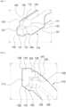
FIG. 2 , theturbine stator 10 further includes avane carrier 13 and a sealingassembly 100, in addition to theturbine casing 11 and theturbine vane 15. - The
vane carrier 13 includes afirst vane carrier 12 and asecond vane carrier 14 disposed axially (in the axial direction X) adjacent to each other on a radially (in the radial direction R) inner side of theturbine casing 11. In addition, theturbine vanes 15 are coupled to inner circumferential surfaces of thefirst vane carrier 12 and thesecond vane carrier 14, respectively. - The sealing
assembly 100 is provided to seal a gap between a first component and a second component. According to the present invention to be described below, a description will be made of the case in which the first component and the second component are thefirst vane carrier 12 and thesecond vane carrier 14, respectively. - Referring to
FIGS. 3 to 6 , the sealingassembly 100 according to the present invention includes a sealingbody 110 having a sealinggroove 120 formed therein and a sealingprotrusion 121 protruding from the sealingbody 110. Aninsertion hole 14a is formed in thesecond vane carrier 14. The sealingassembly 100 is inserted into theinsertion hole 14a. As a plurality of the sealingbodies 110 are coupled to each other along the circumferential direction C, a singleringshaped sealing assembly 100 is formed. Of course, theinsertion hole 14a is also formed in a ring-shape in thesecond vane carrier 14 to correspond to the shape of the sealingassembly 100. - The sealing
protrusion 121 protrudes toward one circumferential side (in the circumferential direction C) from the sealingbody 110. Further, the sealinggroove 120 is formed on the other circumferential side (in the circumferential direction C) of the sealingbody 110. For example, if one circumferential side refers to a side of the sealingbody 110 which is in the clockwise direction of the circumferential direction C, the other circumferential side refers to the other side of the sealingbody 110 which is in the counter-clockwise direction of the circumferential direction C. If there are two adjacent sealingbodies 110 along the circumferential direction C, the sealingprotrusion 121 of afirst sealing body 110 is inserted into a sealinggroove 120 of asecond body part 110. As such, since the plurality of sealingbodies 110 are coupled to each other such that the sealingprotrusions 121 of the sealingbodies 100 are respectively inserted into the sealinggrooves 120 of the adjacent sealingbodies 100, the sealingassembly 100 may more closely seal a gap between thefirst vane carrier 12 and thesecond vane 14 disposed adjacent to each other. - Referring to
FIGS. 4 and5 , according to an embodiment, the sealingprotrusion 121 may have a radially (R) outer surface spaced apart inward from a radially (R) outer surface of the sealing body, and a radially (R) inner surface integrally connected to a radially (R) inner surface of the sealing body. In addition, in the sealingprotrusion 121, a surface of the sealingprotrusion 121 facing thefirst vane carrier 12 is integrally connected to a surface of the sealingbody 110 facing thefirst vane carrier 12, and a surface of the sealingprotrusion 121 facing thesecond vane carrier 14 is spaced apart from a surface of the sealingbody 110 facing thesecond vane carrier 14. Referring toFIG. 6 , the sealinggroove 120 is disposed and formed in a corresponding and opposite way, in terms of the shape, the size and the direction, to the sealingprotrusion 121 of another sealingbody 110 adjacent to the sealingbody 110 in the circumferential direction C. - According to an embodiment, the sealing
body 110 may include afirst body part 111 and asecond body part 112. Thefirst body part 111 may be provided with the sealingprotrusion 121. Thesecond body part 112 may be integrally formed by protruding outward from thefirst body part 111 in the radial direction R. According to an embodiment, the surface of thesecond body part 112 facing thefirst vane carrier 12 may be spaced apart from the surface of thefirst body part 111 facing thefirst vane carrier 12, and the surface of thesecond body part 112 facing thesecond vane carrier 14 may be integrally connected to the surface of thefirst body part 111 facing thesecond vane carrier 14. - In the sealing
assembly 100 according to an embodiment of the present invention, the sealingbody 110 may be provided with at least one of a firstchamfered surface 130, a secondchamfered surface 131, a thirdchamfered surface 132, a fourthchamfered surface 133, a fifthchamfered surface 134, afirst fillet surface 140, and asecond fillet surface 141. - According to an embodiment, the first
chamfered surface 130 may be formed at a radially (R) inner edge portion of thefirst vane carrier 12 side of the sealingbody 110 and the sealingprotrusion 121 along the circumferential direction. The secondchamfered surface 131 may be formed at an edge portion on a radially (R) outer and circumferential (C) side of the sealingprotrusion 121. The thirdchamfered surface 132 may be formed at an edge portion of an inner wall of the sealinggroove 120 that faces the secondchamfered surface 131. The fourthchamfered surfaces 133 may be formed at a radially (R) outer edge portion of thefirst vane carrier 12 side in thefirst body part 111 and a radially (R) inner edge portion of thesecond vane carrier 14 side in thefirst body part 111. The fifthchamfered surface 134 may be formed at a radially (R) outer edge portion in thesecond body part 112. - The
first fillet surface 140 may be formed at a connection portion with the sealingbody 110 in the sealingprotrusion 121. Thesecond fillet surface 141 may be formed on the surface having the sealinggroove 120 in the sealingbody 110 that is corresponding and opposite to thefirst fillet surface 140. - Due to the presence of the first to fifth
chamfered surfaces protrusion 121 and the sealinggroove 120, and the adjacent sealingbodies 110 may be not only easily coupled to each other, but also may produce more effective sealing performance between the adjacentfirst vane carrier 12 and thesecond vane carrier 14. - Although the present invention has been described with reference to the embodiments illustrated in the drawings, the described embodiments are merely illustrative, so those skilled in the art will understand that various modifications and equivalents thereof can be made therefrom. Therefore, the true technical scope of the present invention should be determined by the appended claims.
Claims (7)
- A turbomachine comprising:a stator (10) configured to guide a fluid passing therethrough; anda rotor (20) disposed in the stator (10) configured to rotate with the fluid passing through the stator (10), wherein the stator (10) comprises:a casing (11);first and second vane carriers (12, 14) disposed on a radially inner side of the casing (11) so as to be arranged adjacent to each other along an axial direction of the casing (11);vanes (15) respectively coupled to inner circumferential surfaces of the first and second vane carriers (12, 14); anda sealing assembly (100) sealing a gap between the first and second vane carriers (12, 14), the sealing assembly (100) comprising:a sealing body (110) inserted into an insertion hole (14a) of a respective second vane carrier (14) adjacent to a respective first vane carrier (12); anda sealing protrusion (121) formed on one circumferential side of the sealing body, protruding toward one circumferential direction from the sealing body (110) and configured to be inserted into a sealing groove (120) formed on the other circumferential side of a sealing body (110) of a first adjacent sealing assembly, the sealing body of the first adjacent sealing assembly being adjacent to the sealing body (110) in a circumferential direction,characterized in thatthe sealing protrusion (121) has a radially outer surface spaced apart inward from a radially outer surface of the sealing body (110), and a radially inner surface integrally connected to a radially inner surface of the sealing body (110), a surface of the sealing protrusion (121) facing the first vane carrier (12) is integrally connected to a surface of the sealing body (110) facing the first vane carrier, a surface of the sealing protrusion (121) facing the second vane carrier (14) is spaced apart from a surface of the sealing body (110) facing the second vane carrier (14), andthe sealing groove (120) disposed on the other circumferential side of the sealing body is formed corresponding and opposite to the sealing protrusion (121) of the sealing body (110) and is configured to receive a sealing protrusion of a second adjacent sealing assembly adjacent to the sealing assembly in the other circumferential direction.
- The turbomachine according to claim 1, wherein a first chamfered surface (130) surface is formed on the sealing body (110) and the sealing protrusion (121) at a radially inner edge portion on the first vane carrier (12) side along the circumferential direction,
- The turbomachine according to claim 1 or 2, wherein the sealing protrusion (121) has a second chamfered surface (131) formed on one edge portion of a radially outer and circumferential end, and the sealing groove (120) has a third chamfered surface (132) formed at an edge portion of an inner wall corresponding and opposite to the second chamfered surface (131).
- The turbomachine according to any one of the preceding claims, wherein the sealing protrusion (121) has a first fillet surface (140) formed at a connection portion thereof with the sealing body (110), and the sealing body (110) has a second fillet surface (141) formed on a surface thereof on the side where the sealing groove (120) is formed, corresponding and opposite to the first fillet surface (140).
- The turbomachine according to any one of the preceding claims, wherein the sealing body (110) includes a first body part (111) having the sealing protrusion (121), and a second body part (112) protruding radially outward from the first body part (111) along the circumferential direction, and
wherein the surface of the second body part facing the first vane carrier (12) is spaced apart from the surface of the first body part facing the first vane carrier (12) and the surface of the second body part facing the second vane carrier (14) is integrally connected to the surface of the first body part facing the second vane carrier (14). - The turbomachine according to claim 5, wherein the first body part (111) has fourth chamfered surfaces (133) formed at a radially outer edge portion thereof on the first vane carrier (12) side and a radially inner edge portion thereof on the second vane carrier (14) side, along the circumferential direction, respectively.
- The turbomachine according to claim 6, wherein the second body part (112) has a fifth chamfered surface (134) formed at a radially outer edge portion thereof along the circumferential direction.
Applications Claiming Priority (1)
| Application Number | Priority Date | Filing Date | Title |
|---|---|---|---|
| KR1020210128698AKR102659819B1 (en) | 2021-09-29 | 2021-09-29 | Sealing assembly and turbo-machine comprising the same |
Publications (2)
| Publication Number | Publication Date |
|---|---|
| EP4194665A1 EP4194665A1 (en) | 2023-06-14 |
| EP4194665B1true EP4194665B1 (en) | 2024-04-17 |
Family
ID=82851659
Family Applications (1)
| Application Number | Title | Priority Date | Filing Date |
|---|---|---|---|
| EP22189487.6AActiveEP4194665B1 (en) | 2021-09-29 | 2022-08-09 | Sealing assembly and turbomachine including same |
Country Status (3)
| Country | Link |
|---|---|
| US (1) | US11913339B2 (en) |
| EP (1) | EP4194665B1 (en) |
| KR (1) | KR102659819B1 (en) |
Families Citing this family (1)
| Publication number | Priority date | Publication date | Assignee | Title |
|---|---|---|---|---|
| US20250163818A1 (en)* | 2023-11-22 | 2025-05-22 | Rtx Corporation | Piston ring seal |
Family Cites Families (19)
| Publication number | Priority date | Publication date | Assignee | Title |
|---|---|---|---|---|
| US3575424A (en)* | 1969-11-28 | 1971-04-20 | Koppers Co Inc | Pressure balanced circumferential seal assembly |
| JPH017888Y2 (en)* | 1980-12-18 | 1989-03-02 | ||
| DE60313630T2 (en)* | 2002-07-26 | 2008-01-03 | Nok Corp. | SEAL RING |
| AT505549B1 (en)* | 2008-01-14 | 2009-02-15 | Hoerbiger Kompressortech Hold | GAS DENSITY PISTON RING ARRANGEMENT |
| JPWO2010084853A1 (en) | 2009-01-20 | 2012-07-19 | Nok株式会社 | Seal ring |
| US8430628B2 (en)* | 2009-12-04 | 2013-04-30 | General Electric Company | Pressure balanced low-friction seal |
| JP5546420B2 (en)* | 2010-10-29 | 2014-07-09 | 三菱重工業株式会社 | Turbine |
| JP5781332B2 (en) | 2011-02-28 | 2015-09-24 | 三菱重工業株式会社 | piston ring |
| US8888441B2 (en)* | 2011-08-03 | 2014-11-18 | General Electric Company | Segmented seal assembly |
| US9157530B2 (en) | 2012-03-12 | 2015-10-13 | Nok Corporation | Sealing device and sealing structure |
| US20150115542A1 (en)* | 2013-10-30 | 2015-04-30 | Deere & Company | Ring seal with a double step sealing joint |
| JP6340233B2 (en)* | 2014-04-08 | 2018-06-06 | Kyb株式会社 | Cylinder device |
| US20170307085A1 (en)* | 2016-04-22 | 2017-10-26 | Kaydon Ring & Seal , Inc. | Circumferential shaft seal with radial displacement control |
| JP2018028332A (en)* | 2016-08-15 | 2018-02-22 | 株式会社リケン | piston ring |
| CN107939455B (en)* | 2017-11-10 | 2024-05-17 | 中国联合重型燃气轮机技术有限公司 | Gas turbine and seal assembly thereof |
| US11525515B2 (en)* | 2020-02-11 | 2022-12-13 | Raytheon Technologies Corporation | Radial seal segment joint |
| KR102291086B1 (en) | 2020-02-21 | 2021-08-18 | 두산중공업 주식회사 | Sealing assembly and gas turbine comprising the same |
| US11549444B2 (en)* | 2021-02-05 | 2023-01-10 | Raytheon Technologies Corporation | Hybrid seal dual runner |
| GB2605563B (en)* | 2021-03-15 | 2024-09-04 | Crane John Uk Ltd | A radial separation seal |
- 2021
- 2021-09-29KRKR1020210128698Apatent/KR102659819B1/enactiveActive
- 2022
- 2022-07-20USUS17/813,623patent/US11913339B2/enactiveActive
- 2022-08-09EPEP22189487.6Apatent/EP4194665B1/enactiveActive
Also Published As
| Publication number | Publication date |
|---|---|
| KR102659819B1 (en) | 2024-04-23 |
| EP4194665A1 (en) | 2023-06-14 |
| US20230096973A1 (en) | 2023-03-30 |
| KR20230045874A (en) | 2023-04-05 |
| US11913339B2 (en) | 2024-02-27 |
Similar Documents
| Publication | Publication Date | Title |
|---|---|---|
| KR102126882B1 (en) | Nozzle assembly, combustor and gas turbine including the same | |
| EP3470625B1 (en) | Rotor disk assembly for gas turbine | |
| US10801347B2 (en) | Sealing assembly and gas turbine including the same | |
| EP4194665B1 (en) | Sealing assembly and turbomachine including same | |
| KR102440257B1 (en) | Sealing assembly and turbo-machine comprising the same | |
| US12129766B2 (en) | Vertical joint coupling structure of casing, and gas turbine having same | |
| KR101953462B1 (en) | Vane assembly and gas turbine including vane assembly | |
| KR20210106658A (en) | Sealing assembly and gas turbine comprising the same | |
| KR102433705B1 (en) | Stator and turbo-machine comprising the same | |
| KR102401100B1 (en) | rotor and turbo-machine comprising the same | |
| KR102510535B1 (en) | Ring segment and turbo-machine comprising the same | |
| KR102655158B1 (en) | Sealing assembly and turbo-machine comprising the same | |
| KR20220135409A (en) | Nozzle assembly, combustor and gas turbine comprising the same | |
| US12168934B2 (en) | Turbine vane platform sealing assembly, and turbine vane and gas turbine including same | |
| KR102587218B1 (en) | Rotor and turbo-machine comprising the same | |
| KR102655156B1 (en) | Stator for turbo-machine | |
| US20240003545A1 (en) | Jet nozzle, combustor, and gas turbine including same | |
| US12247742B2 (en) | Jet nozzle, combustor, and gas turbine including same | |
| US12078346B2 (en) | Hollow nozzle, combustor including hollow nozzle, and gas turbine including combustor | |
| US12404774B2 (en) | Blade fastening assembly and gas turbine including same | |
| KR102433706B1 (en) | Nozzle assembly, Combustor and Gas turbine comprising the same | |
| KR102120097B1 (en) | Stationary vane nozzle of gas turbine | |
| KR20250119892A (en) | Seal assembly structure of turbine blade and gas turbine including same | |
| KR20200029836A (en) | Cross-fire tube, combustor and gas turbine including the same | |
| KR20190103763A (en) | Seal plate of turbine, turbine and gas turbine comprising it |
Legal Events
| Date | Code | Title | Description |
|---|---|---|---|
| PUAI | Public reference made under article 153(3) epc to a published international application that has entered the european phase | Free format text:ORIGINAL CODE: 0009012 | |
| STAA | Information on the status of an ep patent application or granted ep patent | Free format text:STATUS: REQUEST FOR EXAMINATION WAS MADE | |
| 17P | Request for examination filed | Effective date:20220809 | |
| AK | Designated contracting states | Kind code of ref document:A1 Designated state(s):AL AT BE BG CH CY CZ DE DK EE ES FI FR GB GR HR HU IE IS IT LI LT LU LV MC MK MT NL NO PL PT RO RS SE SI SK SM TR | |
| RBV | Designated contracting states (corrected) | Designated state(s):AL AT BE BG CH CY CZ DE DK EE ES FI FR GB GR HR HU IE IS IT LI LT LU LV MC MK MT NL NO PL PT RO RS SE SI SK SM TR | |
| GRAP | Despatch of communication of intention to grant a patent | Free format text:ORIGINAL CODE: EPIDOSNIGR1 | |
| STAA | Information on the status of an ep patent application or granted ep patent | Free format text:STATUS: GRANT OF PATENT IS INTENDED | |
| INTG | Intention to grant announced | Effective date:20231110 | |
| GRAS | Grant fee paid | Free format text:ORIGINAL CODE: EPIDOSNIGR3 | |
| GRAA | (expected) grant | Free format text:ORIGINAL CODE: 0009210 | |
| STAA | Information on the status of an ep patent application or granted ep patent | Free format text:STATUS: THE PATENT HAS BEEN GRANTED | |
| AK | Designated contracting states | Kind code of ref document:B1 Designated state(s):AL AT BE BG CH CY CZ DE DK EE ES FI FR GB GR HR HU IE IS IT LI LT LU LV MC MK MT NL NO PL PT RO RS SE SI SK SM TR | |
| REG | Reference to a national code | Ref country code:GB Ref legal event code:FG4D | |
| REG | Reference to a national code | Ref country code:CH Ref legal event code:EP | |
| REG | Reference to a national code | Ref country code:IE Ref legal event code:FG4D Ref country code:DE Ref legal event code:R096 Ref document number:602022002905 Country of ref document:DE | |
| REG | Reference to a national code | Ref country code:LT Ref legal event code:MG9D | |
| REG | Reference to a national code | Ref country code:NL Ref legal event code:MP Effective date:20240417 | |
| REG | Reference to a national code | Ref country code:AT Ref legal event code:MK05 Ref document number:1677434 Country of ref document:AT Kind code of ref document:T Effective date:20240417 | |
| PG25 | Lapsed in a contracting state [announced via postgrant information from national office to epo] | Ref country code:NL Free format text:LAPSE BECAUSE OF FAILURE TO SUBMIT A TRANSLATION OF THE DESCRIPTION OR TO PAY THE FEE WITHIN THE PRESCRIBED TIME-LIMIT Effective date:20240417 | |
| PG25 | Lapsed in a contracting state [announced via postgrant information from national office to epo] | Ref country code:NL Free format text:LAPSE BECAUSE OF FAILURE TO SUBMIT A TRANSLATION OF THE DESCRIPTION OR TO PAY THE FEE WITHIN THE PRESCRIBED TIME-LIMIT Effective date:20240417 | |
| PG25 | Lapsed in a contracting state [announced via postgrant information from national office to epo] | Ref country code:IS Free format text:LAPSE BECAUSE OF FAILURE TO SUBMIT A TRANSLATION OF THE DESCRIPTION OR TO PAY THE FEE WITHIN THE PRESCRIBED TIME-LIMIT Effective date:20240817 | |
| PG25 | Lapsed in a contracting state [announced via postgrant information from national office to epo] | Ref country code:BG Free format text:LAPSE BECAUSE OF FAILURE TO SUBMIT A TRANSLATION OF THE DESCRIPTION OR TO PAY THE FEE WITHIN THE PRESCRIBED TIME-LIMIT Effective date:20240417 | |
| PG25 | Lapsed in a contracting state [announced via postgrant information from national office to epo] | Ref country code:HR Free format text:LAPSE BECAUSE OF FAILURE TO SUBMIT A TRANSLATION OF THE DESCRIPTION OR TO PAY THE FEE WITHIN THE PRESCRIBED TIME-LIMIT Effective date:20240417 Ref country code:FI Free format text:LAPSE BECAUSE OF FAILURE TO SUBMIT A TRANSLATION OF THE DESCRIPTION OR TO PAY THE FEE WITHIN THE PRESCRIBED TIME-LIMIT Effective date:20240417 | |
| PGFP | Annual fee paid to national office [announced via postgrant information from national office to epo] | Ref country code:DE Payment date:20240812 Year of fee payment:3 | |
| PG25 | Lapsed in a contracting state [announced via postgrant information from national office to epo] | Ref country code:GR Free format text:LAPSE BECAUSE OF FAILURE TO SUBMIT A TRANSLATION OF THE DESCRIPTION OR TO PAY THE FEE WITHIN THE PRESCRIBED TIME-LIMIT Effective date:20240718 | |
| PG25 | Lapsed in a contracting state [announced via postgrant information from national office to epo] | Ref country code:PT Free format text:LAPSE BECAUSE OF FAILURE TO SUBMIT A TRANSLATION OF THE DESCRIPTION OR TO PAY THE FEE WITHIN THE PRESCRIBED TIME-LIMIT Effective date:20240819 | |
| PG25 | Lapsed in a contracting state [announced via postgrant information from national office to epo] | Ref country code:ES Free format text:LAPSE BECAUSE OF FAILURE TO SUBMIT A TRANSLATION OF THE DESCRIPTION OR TO PAY THE FEE WITHIN THE PRESCRIBED TIME-LIMIT Effective date:20240417 | |
| PG25 | Lapsed in a contracting state [announced via postgrant information from national office to epo] | Ref country code:AT Free format text:LAPSE BECAUSE OF FAILURE TO SUBMIT A TRANSLATION OF THE DESCRIPTION OR TO PAY THE FEE WITHIN THE PRESCRIBED TIME-LIMIT Effective date:20240417 | |
| PG25 | Lapsed in a contracting state [announced via postgrant information from national office to epo] | Ref country code:PL Free format text:LAPSE BECAUSE OF FAILURE TO SUBMIT A TRANSLATION OF THE DESCRIPTION OR TO PAY THE FEE WITHIN THE PRESCRIBED TIME-LIMIT Effective date:20240417 | |
| PG25 | Lapsed in a contracting state [announced via postgrant information from national office to epo] | Ref country code:LV Free format text:LAPSE BECAUSE OF FAILURE TO SUBMIT A TRANSLATION OF THE DESCRIPTION OR TO PAY THE FEE WITHIN THE PRESCRIBED TIME-LIMIT Effective date:20240417 | |
| PG25 | Lapsed in a contracting state [announced via postgrant information from national office to epo] | Ref country code:PT Free format text:LAPSE BECAUSE OF FAILURE TO SUBMIT A TRANSLATION OF THE DESCRIPTION OR TO PAY THE FEE WITHIN THE PRESCRIBED TIME-LIMIT Effective date:20240819 Ref country code:PL Free format text:LAPSE BECAUSE OF FAILURE TO SUBMIT A TRANSLATION OF THE DESCRIPTION OR TO PAY THE FEE WITHIN THE PRESCRIBED TIME-LIMIT Effective date:20240417 Ref country code:NO Free format text:LAPSE BECAUSE OF FAILURE TO SUBMIT A TRANSLATION OF THE DESCRIPTION OR TO PAY THE FEE WITHIN THE PRESCRIBED TIME-LIMIT Effective date:20240717 Ref country code:LV Free format text:LAPSE BECAUSE OF FAILURE TO SUBMIT A TRANSLATION OF THE DESCRIPTION OR TO PAY THE FEE WITHIN THE PRESCRIBED TIME-LIMIT Effective date:20240417 Ref country code:IS Free format text:LAPSE BECAUSE OF FAILURE TO SUBMIT A TRANSLATION OF THE DESCRIPTION OR TO PAY THE FEE WITHIN THE PRESCRIBED TIME-LIMIT Effective date:20240817 Ref country code:HR Free format text:LAPSE BECAUSE OF FAILURE TO SUBMIT A TRANSLATION OF THE DESCRIPTION OR TO PAY THE FEE WITHIN THE PRESCRIBED TIME-LIMIT Effective date:20240417 Ref country code:GR Free format text:LAPSE BECAUSE OF FAILURE TO SUBMIT A TRANSLATION OF THE DESCRIPTION OR TO PAY THE FEE WITHIN THE PRESCRIBED TIME-LIMIT Effective date:20240718 Ref country code:FI Free format text:LAPSE BECAUSE OF FAILURE TO SUBMIT A TRANSLATION OF THE DESCRIPTION OR TO PAY THE FEE WITHIN THE PRESCRIBED TIME-LIMIT Effective date:20240417 Ref country code:ES Free format text:LAPSE BECAUSE OF FAILURE TO SUBMIT A TRANSLATION OF THE DESCRIPTION OR TO PAY THE FEE WITHIN THE PRESCRIBED TIME-LIMIT Effective date:20240417 Ref country code:BG Free format text:LAPSE BECAUSE OF FAILURE TO SUBMIT A TRANSLATION OF THE DESCRIPTION OR TO PAY THE FEE WITHIN THE PRESCRIBED TIME-LIMIT Effective date:20240417 Ref country code:AT Free format text:LAPSE BECAUSE OF FAILURE TO SUBMIT A TRANSLATION OF THE DESCRIPTION OR TO PAY THE FEE WITHIN THE PRESCRIBED TIME-LIMIT Effective date:20240417 Ref country code:RS Free format text:LAPSE BECAUSE OF FAILURE TO SUBMIT A TRANSLATION OF THE DESCRIPTION OR TO PAY THE FEE WITHIN THE PRESCRIBED TIME-LIMIT Effective date:20240717 | |
| PG25 | Lapsed in a contracting state [announced via postgrant information from national office to epo] | Ref country code:DK Free format text:LAPSE BECAUSE OF FAILURE TO SUBMIT A TRANSLATION OF THE DESCRIPTION OR TO PAY THE FEE WITHIN THE PRESCRIBED TIME-LIMIT Effective date:20240417 | |
| REG | Reference to a national code | Ref country code:DE Ref legal event code:R097 Ref document number:602022002905 Country of ref document:DE | |
| PG25 | Lapsed in a contracting state [announced via postgrant information from national office to epo] | Ref country code:EE Free format text:LAPSE BECAUSE OF FAILURE TO SUBMIT A TRANSLATION OF THE DESCRIPTION OR TO PAY THE FEE WITHIN THE PRESCRIBED TIME-LIMIT Effective date:20240417 | |
| PG25 | Lapsed in a contracting state [announced via postgrant information from national office to epo] | Ref country code:CZ Free format text:LAPSE BECAUSE OF FAILURE TO SUBMIT A TRANSLATION OF THE DESCRIPTION OR TO PAY THE FEE WITHIN THE PRESCRIBED TIME-LIMIT Effective date:20240417 | |
| PG25 | Lapsed in a contracting state [announced via postgrant information from national office to epo] | Ref country code:SK Free format text:LAPSE BECAUSE OF FAILURE TO SUBMIT A TRANSLATION OF THE DESCRIPTION OR TO PAY THE FEE WITHIN THE PRESCRIBED TIME-LIMIT Effective date:20240417 Ref country code:RO Free format text:LAPSE BECAUSE OF FAILURE TO SUBMIT A TRANSLATION OF THE DESCRIPTION OR TO PAY THE FEE WITHIN THE PRESCRIBED TIME-LIMIT Effective date:20240417 | |
| PG25 | Lapsed in a contracting state [announced via postgrant information from national office to epo] | Ref country code:SM Free format text:LAPSE BECAUSE OF FAILURE TO SUBMIT A TRANSLATION OF THE DESCRIPTION OR TO PAY THE FEE WITHIN THE PRESCRIBED TIME-LIMIT Effective date:20240417 | |
| PG25 | Lapsed in a contracting state [announced via postgrant information from national office to epo] | Ref country code:SM Free format text:LAPSE BECAUSE OF FAILURE TO SUBMIT A TRANSLATION OF THE DESCRIPTION OR TO PAY THE FEE WITHIN THE PRESCRIBED TIME-LIMIT Effective date:20240417 Ref country code:SK Free format text:LAPSE BECAUSE OF FAILURE TO SUBMIT A TRANSLATION OF THE DESCRIPTION OR TO PAY THE FEE WITHIN THE PRESCRIBED TIME-LIMIT Effective date:20240417 Ref country code:RO Free format text:LAPSE BECAUSE OF FAILURE TO SUBMIT A TRANSLATION OF THE DESCRIPTION OR TO PAY THE FEE WITHIN THE PRESCRIBED TIME-LIMIT Effective date:20240417 Ref country code:EE Free format text:LAPSE BECAUSE OF FAILURE TO SUBMIT A TRANSLATION OF THE DESCRIPTION OR TO PAY THE FEE WITHIN THE PRESCRIBED TIME-LIMIT Effective date:20240417 Ref country code:DK Free format text:LAPSE BECAUSE OF FAILURE TO SUBMIT A TRANSLATION OF THE DESCRIPTION OR TO PAY THE FEE WITHIN THE PRESCRIBED TIME-LIMIT Effective date:20240417 Ref country code:CZ Free format text:LAPSE BECAUSE OF FAILURE TO SUBMIT A TRANSLATION OF THE DESCRIPTION OR TO PAY THE FEE WITHIN THE PRESCRIBED TIME-LIMIT Effective date:20240417 | |
| PG25 | Lapsed in a contracting state [announced via postgrant information from national office to epo] | Ref country code:IT Free format text:LAPSE BECAUSE OF FAILURE TO SUBMIT A TRANSLATION OF THE DESCRIPTION OR TO PAY THE FEE WITHIN THE PRESCRIBED TIME-LIMIT Effective date:20240417 | |
| PLBE | No opposition filed within time limit | Free format text:ORIGINAL CODE: 0009261 | |
| STAA | Information on the status of an ep patent application or granted ep patent | Free format text:STATUS: NO OPPOSITION FILED WITHIN TIME LIMIT | |
| 26N | No opposition filed | Effective date:20250120 | |
| PG25 | Lapsed in a contracting state [announced via postgrant information from national office to epo] | Ref country code:LU Free format text:LAPSE BECAUSE OF NON-PAYMENT OF DUE FEES Effective date:20240809 | |
| PG25 | Lapsed in a contracting state [announced via postgrant information from national office to epo] | Ref country code:SI Free format text:LAPSE BECAUSE OF FAILURE TO SUBMIT A TRANSLATION OF THE DESCRIPTION OR TO PAY THE FEE WITHIN THE PRESCRIBED TIME-LIMIT Effective date:20240417 Ref country code:MC Free format text:LAPSE BECAUSE OF FAILURE TO SUBMIT A TRANSLATION OF THE DESCRIPTION OR TO PAY THE FEE WITHIN THE PRESCRIBED TIME-LIMIT Effective date:20240417 | |
| REG | Reference to a national code | Ref country code:BE Ref legal event code:MM Effective date:20240831 | |
| PG25 | Lapsed in a contracting state [announced via postgrant information from national office to epo] | Ref country code:BE Free format text:LAPSE BECAUSE OF NON-PAYMENT OF DUE FEES Effective date:20240831 | |
| PG25 | Lapsed in a contracting state [announced via postgrant information from national office to epo] | Ref country code:FR Free format text:LAPSE BECAUSE OF NON-PAYMENT OF DUE FEES Effective date:20240831 | |
| PG25 | Lapsed in a contracting state [announced via postgrant information from national office to epo] | Ref country code:IE Free format text:LAPSE BECAUSE OF NON-PAYMENT OF DUE FEES Effective date:20240809 | |
| PG25 | Lapsed in a contracting state [announced via postgrant information from national office to epo] | Ref country code:SE Free format text:LAPSE BECAUSE OF FAILURE TO SUBMIT A TRANSLATION OF THE DESCRIPTION OR TO PAY THE FEE WITHIN THE PRESCRIBED TIME-LIMIT Effective date:20240417 |