EP4193899B1 - Floor cleaning machine with sweeping lip - Google Patents
Floor cleaning machine with sweeping lipDownload PDFInfo
- Publication number
- EP4193899B1 EP4193899B1EP23150893.8AEP23150893AEP4193899B1EP 4193899 B1EP4193899 B1EP 4193899B1EP 23150893 AEP23150893 AEP 23150893AEP 4193899 B1EP4193899 B1EP 4193899B1
- Authority
- EP
- European Patent Office
- Prior art keywords
- cleaning roller
- mouth
- floor
- cleaning
- mouth wall
- Prior art date
- Legal status (The legal status is an assumption and is not a legal conclusion. Google has not performed a legal analysis and makes no representation as to the accuracy of the status listed.)
- Active
Links
Images


Classifications
- A—HUMAN NECESSITIES
- A47—FURNITURE; DOMESTIC ARTICLES OR APPLIANCES; COFFEE MILLS; SPICE MILLS; SUCTION CLEANERS IN GENERAL
- A47L—DOMESTIC WASHING OR CLEANING; SUCTION CLEANERS IN GENERAL
- A47L11/00—Machines for cleaning floors, carpets, furniture, walls, or wall coverings
- A47L11/34—Machines for treating carpets in position by liquid, foam, or vapour, e.g. by steam
- A—HUMAN NECESSITIES
- A47—FURNITURE; DOMESTIC ARTICLES OR APPLIANCES; COFFEE MILLS; SPICE MILLS; SUCTION CLEANERS IN GENERAL
- A47L—DOMESTIC WASHING OR CLEANING; SUCTION CLEANERS IN GENERAL
- A47L11/00—Machines for cleaning floors, carpets, furniture, walls, or wall coverings
- A47L11/02—Floor surfacing or polishing machines
- A47L11/20—Floor surfacing or polishing machines combined with vacuum cleaning devices
- A—HUMAN NECESSITIES
- A47—FURNITURE; DOMESTIC ARTICLES OR APPLIANCES; COFFEE MILLS; SPICE MILLS; SUCTION CLEANERS IN GENERAL
- A47L—DOMESTIC WASHING OR CLEANING; SUCTION CLEANERS IN GENERAL
- A47L11/00—Machines for cleaning floors, carpets, furniture, walls, or wall coverings
- A47L11/26—Floor-scrubbing machines, hand-driven
- A—HUMAN NECESSITIES
- A47—FURNITURE; DOMESTIC ARTICLES OR APPLIANCES; COFFEE MILLS; SPICE MILLS; SUCTION CLEANERS IN GENERAL
- A47L—DOMESTIC WASHING OR CLEANING; SUCTION CLEANERS IN GENERAL
- A47L11/00—Machines for cleaning floors, carpets, furniture, walls, or wall coverings
- A47L11/02—Floor surfacing or polishing machines
- A47L11/20—Floor surfacing or polishing machines combined with vacuum cleaning devices
- A47L11/204—Floor surfacing or polishing machines combined with vacuum cleaning devices having combined drive for brushes and for vacuum cleaning
- A—HUMAN NECESSITIES
- A47—FURNITURE; DOMESTIC ARTICLES OR APPLIANCES; COFFEE MILLS; SPICE MILLS; SUCTION CLEANERS IN GENERAL
- A47L—DOMESTIC WASHING OR CLEANING; SUCTION CLEANERS IN GENERAL
- A47L11/00—Machines for cleaning floors, carpets, furniture, walls, or wall coverings
- A47L11/29—Floor-scrubbing machines characterised by means for taking-up dirty liquid
- A47L11/30—Floor-scrubbing machines characterised by means for taking-up dirty liquid by suction
- A47L11/302—Floor-scrubbing machines characterised by means for taking-up dirty liquid by suction having rotary tools
- A—HUMAN NECESSITIES
- A47—FURNITURE; DOMESTIC ARTICLES OR APPLIANCES; COFFEE MILLS; SPICE MILLS; SUCTION CLEANERS IN GENERAL
- A47L—DOMESTIC WASHING OR CLEANING; SUCTION CLEANERS IN GENERAL
- A47L11/00—Machines for cleaning floors, carpets, furniture, walls, or wall coverings
- A47L11/40—Parts or details of machines not provided for in groups A47L11/02 - A47L11/38, or not restricted to one of these groups, e.g. handles, arrangements of switches, skirts, buffers, levers
- A47L11/4013—Contaminants collecting devices, i.e. hoppers, tanks or the like
- A47L11/4016—Contaminants collecting devices, i.e. hoppers, tanks or the like specially adapted for collecting fluids
- A—HUMAN NECESSITIES
- A47—FURNITURE; DOMESTIC ARTICLES OR APPLIANCES; COFFEE MILLS; SPICE MILLS; SUCTION CLEANERS IN GENERAL
- A47L—DOMESTIC WASHING OR CLEANING; SUCTION CLEANERS IN GENERAL
- A47L11/00—Machines for cleaning floors, carpets, furniture, walls, or wall coverings
- A47L11/40—Parts or details of machines not provided for in groups A47L11/02 - A47L11/38, or not restricted to one of these groups, e.g. handles, arrangements of switches, skirts, buffers, levers
- A47L11/4036—Parts or details of the surface treating tools
- A47L11/4041—Roll shaped surface treating tools
- A—HUMAN NECESSITIES
- A47—FURNITURE; DOMESTIC ARTICLES OR APPLIANCES; COFFEE MILLS; SPICE MILLS; SUCTION CLEANERS IN GENERAL
- A47L—DOMESTIC WASHING OR CLEANING; SUCTION CLEANERS IN GENERAL
- A47L11/00—Machines for cleaning floors, carpets, furniture, walls, or wall coverings
- A47L11/40—Parts or details of machines not provided for in groups A47L11/02 - A47L11/38, or not restricted to one of these groups, e.g. handles, arrangements of switches, skirts, buffers, levers
- A47L11/4036—Parts or details of the surface treating tools
- A47L11/4044—Vacuuming or pick-up tools; Squeegees
- A—HUMAN NECESSITIES
- A47—FURNITURE; DOMESTIC ARTICLES OR APPLIANCES; COFFEE MILLS; SPICE MILLS; SUCTION CLEANERS IN GENERAL
- A47L—DOMESTIC WASHING OR CLEANING; SUCTION CLEANERS IN GENERAL
- A47L11/00—Machines for cleaning floors, carpets, furniture, walls, or wall coverings
- A47L11/40—Parts or details of machines not provided for in groups A47L11/02 - A47L11/38, or not restricted to one of these groups, e.g. handles, arrangements of switches, skirts, buffers, levers
- A47L11/408—Means for supplying cleaning or surface treating agents
- A47L11/4083—Liquid supply reservoirs; Preparation of the agents, e.g. mixing devices
- A—HUMAN NECESSITIES
- A47—FURNITURE; DOMESTIC ARTICLES OR APPLIANCES; COFFEE MILLS; SPICE MILLS; SUCTION CLEANERS IN GENERAL
- A47L—DOMESTIC WASHING OR CLEANING; SUCTION CLEANERS IN GENERAL
- A47L5/00—Structural features of suction cleaners
- A47L5/12—Structural features of suction cleaners with power-driven air-pumps or air-compressors, e.g. driven by motor vehicle engine vacuum
- A47L5/22—Structural features of suction cleaners with power-driven air-pumps or air-compressors, e.g. driven by motor vehicle engine vacuum with rotary fans
- A47L5/24—Hand-supported suction cleaners
- A—HUMAN NECESSITIES
- A47—FURNITURE; DOMESTIC ARTICLES OR APPLIANCES; COFFEE MILLS; SPICE MILLS; SUCTION CLEANERS IN GENERAL
- A47L—DOMESTIC WASHING OR CLEANING; SUCTION CLEANERS IN GENERAL
- A47L9/00—Details or accessories of suction cleaners, e.g. mechanical means for controlling the suction or for effecting pulsating action; Storing devices specially adapted to suction cleaners or parts thereof; Carrying-vehicles specially adapted for suction cleaners
- A47L9/02—Nozzles
- A47L9/04—Nozzles with driven brushes or agitators
- A47L9/0405—Driving means for the brushes or agitators
- A47L9/0411—Driving means for the brushes or agitators driven by electric motor
- A—HUMAN NECESSITIES
- A47—FURNITURE; DOMESTIC ARTICLES OR APPLIANCES; COFFEE MILLS; SPICE MILLS; SUCTION CLEANERS IN GENERAL
- A47L—DOMESTIC WASHING OR CLEANING; SUCTION CLEANERS IN GENERAL
- A47L9/00—Details or accessories of suction cleaners, e.g. mechanical means for controlling the suction or for effecting pulsating action; Storing devices specially adapted to suction cleaners or parts thereof; Carrying-vehicles specially adapted for suction cleaners
- A47L9/32—Handles
- A47L9/322—Handles for hand-supported suction cleaners
Definitions
- the inventionrelates to a floor cleaning machine which is hand-guided and/or hand-held, comprising a carrier device, at least one cleaning roller which is arranged on the carrier device, can be driven in rotation and is provided with a trim, a blower device for generating a suction flow, and a suction channel device for the suction flow, which provides at least one suction channel with a fluid-effective connection between the blower device and the at least one cleaning roller, wherein the at least one suction channel has at least one mouth towards the at least one cleaning roller and the at least one mouth has a first mouth wall and a spaced-apart second mouth wall, between which a mouth opening is formed, wherein when at least one cleaning roller is placed on a floor to be cleaned, the first mouth wall is positioned above the second mouth wall with respect to the direction of gravity.
- a brush devicethat can be connected to a water pipe is known in which a brush roller that is permeable to water in the casing area is rotatably mounted on a perforated hollow shaft that can be fed with water.
- a device for treating a surfacewhich has a wiping device with a cloth-like wiping element that can be guided over the surface to be cleaned, a moistening device for moistening the wiping element and a suction device for suctioning the wiping element.
- US-A-20060236494discloses a floor cleaning machine according to the preamble of claim 1.
- the inventionis based on the object of providing a floor cleaning machine of the type mentioned above, which delivers an optimized cleaning result while being easy to handle.
- the first mouth wall and/or the second mouth wallrests on the trim of the at least one cleaning roller or projects into it, and in that at least one sweeping lip is arranged on the suction channel device.
- At least one outlet wallrests against the trim of the at least one cleaning roller or protrudes into it (i.e. dips into it) results in an optimized suction result.
- the at least one cleaning rolleris guided past the at least one outlet, at which a negative pressure is applied, i.e. a suction flow is generated, and dirt can be sucked in.
- a front side of the first mouth wall and/or a front side of the second mouth wallis at least approximately parallel to a rotation axis of the at least one cleaning roller. This results in effective suction.
- a wiping function with suctioncan be implemented.
- the first mouth wallcan rest against the trim or protrude into it and the second mouth wall can rest against the trim of the at least one cleaning roller or be spaced apart from it or protrude into it or, if the second mouth wall rests against the trim or protrudes into it, the first mouth wall can rest against the trim or protrude into it or be spaced apart.
- the first mouth wallrests against the trim or protrudes into it and a direction of rotation of the at least one cleaning roller is such that first a certain point of the at least one cleaning roller is guided past the second mouth wall and then past the first mouth wall.
- a direction of rotationis in particular such that a certain point of the at least one cleaning roller is guided past the first mouth wall and then past the second mouth wall.
- a contact elementis arranged on the mouth, which rests on the trimmings or projects into them, and which projects transversely away from the first mouth wall or the second mouth wall, with a fluid seal between the contact element and the corresponding mouth wall.
- the contact elementincreases the area of contact or projection into the trimmings and a higher fluid tightness is achieved, which in turn improves the suction.
- the contact elementforms (in cross section) a type of beak, which projects away from the first mouth wall or the second mouth wall.
- the at least one cleaning rolleris guided past the contact element during rotation.
- the contact elementis located on the first mouth wall. This makes it easy to achieve an improved Achieve a suction effect. A fluid tightness between the contact element and the mouth can be achieved in a simple manner.
- the contact element facing the at least one cleaning rollerhas a curved contour which is adapted to the at least one cleaning roller.
- the contourhas a circular contour adapted to a corresponding circular contour of the at least one cleaning roller at least with respect to an envelope. This minimizes the frictional resistance caused by the at least one cleaning roller rotating past the contact element.
- the contact elementhas a first end which is spaced from the mouth and has a second end which is positioned at the mouth, wherein the contact element is advantageously designed such that a negative pressure that arises at the first end is smaller than at the second end. This reduces the risk of a "fluid short circuit" through which fluid and in particular liquid could be sucked out in the area of the first end. This improves the cleaning result.
- a design for reducing the negative pressure that develops at the first end compared to the second endcan be such that the contact element is made sufficiently long, whereby an increased friction surface is then provided.
- the contact elementhas a first region with the first end and a second region with the second end, whereby a distance of the contact element at the first region to a rotation axis of the at least one cleaning roller is greater than at the second region. This allows the negative pressure that develops in the region of the first end to be reduced compared to the region at the second end and the risk of a liquid short circuit is reduced.
- This designcan be achieved in a simple manner by a corresponding surface design of the contact element facing the at least one cleaning roller.
- the contact elementis formed in steps on the corresponding surface, whereby the step in particular has a smooth course (without sharp edges).
- the second mouth wallis arranged in front of the first mouth wall in relation to a direction of rotation of the at least one cleaning roller. A certain area on the cleaning roller is then guided past the second mouth wall and then the first mouth wall when the cleaning roller rotates. This results in effective suction and ease of use.
- This embodimentresults in a short path for supplying dirt particles adhering to the trim to the mouth.
- this direction of rotationis advantageous when cleaning from a room using the corresponding floor cleaning machine.
- a distance between a front side of the first mouth wall and a rotation axis of the at least one cleaning rolleris smaller than a distance between a front side of the second mouth wall and the rotation axis.
- the mouth opening of at least one mouthhas at least an approximately rectangular cross-section. This allows the cleaning roller to be vacuumed from the outside over a large area and results in effective dirt extraction.
- the at least one suction channelis tapered towards a separator device.
- a type of funnelis arranged on the suction channel in order to enable effective dirt extraction from the cleaning roller.
- a large cross-sectional areacan be provided at the mouth and in the further course of the at least one suction channel up to the taper, which is advantageous in terms of flow.
- the taper near the separator deviceallows the flow speed to be increased.
- At least one cleaning fluid containeris provided, which is in fluid connection with the at least one cleaning roller, wherein cleaning fluid is provided on the at least one cleaning roller, in particular via an interior of the at least one cleaning roller.
- cleaning fluidis provided on the at least one cleaning roller, in particular via an interior of the at least one cleaning roller.
- the cleaning fluid containeris arranged on the floor cleaning machine in particular in a removable manner.
- the at least one cleaning fluid containeris arranged on a user holding unit. It can thus be effectively positioned on the floor cleaning machine and positioned above the at least one cleaning roller with respect to the direction of gravity.
- blower deviceis arranged on the support device and/or the suction channel device is arranged on the support device. This results in a simple structural design.
- the suction channel devicecomprises a housing in which the at least one suction channel is arranged or formed.
- the housingcan be used, for example, to accommodate a dirty liquid container and/or a separator device. It can also be used, for example, to accommodate a battery device and in particular a rechargeable battery device.
- an elastic deviceis provided by which the suction channel device is pressed elastically against the at least one cleaning roller, wherein the elastic device is or comprises in particular a spring device. This makes it easy to achieve that the first and/or second mouth wall rests against the trim of the at least one cleaning roller or is pressed into it. This corresponding functionality is ensured even if the trim is worn away, at least up to a certain threshold.
- the elastic deviceis supported on the carrier device via a first side.
- the carrier devicethen forms a mounting surface for the elastic device.
- the elastic deviceprefferably supported on a first side on the blower device or a separator device.
- the blower device or separator devicethen forms a mounting surface for the elastic device.
- the elastic deviceis supported on the suction channel device via a second side. This exerts a corresponding pre-tensioning force directly on the suction channel device, which presses it with the first mouth wall against the trimmings.
- the elastic deviceprefferably supported on a second side by the blower device or the separator device, whereby the blower device or the separator device is connected to the suction channel device, whereby the connection is a direct connection or a frictional connection.
- the suction channel deviceis then pressed against the trimmings directly or by frictional connection via the blower device or the separator device.
- a dirty liquid containerwhich is associated with a separator device. This allows dirty cleaning liquid to be collected.
- a separator deviceair is separated from liquid and solid components in a suction stream.
- the dirty liquid containeris arranged on the suction channel device. This results in a compact structure and flow paths can be minimized.
- a user holding unitis arranged on the carrier device, which is arranged in particular so that it can pivot on a joint. An operator can then operate the floor cleaning machine in a simple manner and, for example, operate it with one hand. He can push or pull it and also work on a larger floor area while minimizing changes of location.
- a pivot axis of the jointis parallel to a rotation axis of the at least one cleaning roller. This results in easy operation.
- the user holding unitcomprises a rod device, for example with a rod on which a handle is located. This results in a compact structure with easy operation.
- the floor cleaning machineis only supported on the floor by the at least one cleaning roller and is particularly characterized by a design without support wheels. This results in a compact structure.
- the entire weight of the floor cleaning machinecan be supported by the at least one cleaning roller.
- a design without support wheelsprevents abrasion marks on the floor to be cleaned.
- the direction of rotation of the at least one cleaning rolleris from a line of contact with the floor to be cleaned towards the second mouth wall and then towards the first mouth wall and in particular the direction of rotation is clockwise when the at least one cleaning roller is placed on the floor. This allows a effective operation in which the floor cleaning machine is led out of a room to be cleaned.
- the at least one cleaning rolleris provided with grooves for generating air pulses in a suction flow.
- Short air pulsescan be generated by means of grooves and in particular spaced grooves which are rotated through the mouth at which the suction flow is present. Dirt which has adhered to the trim and in particular textile trim of the cleaning roller can be carried along via these. This enables an effective cleaning effect to be achieved.
- a grooveis formed in particular by a region free of or with reduced amounts of debris in order to be able to cause corresponding air pulses in the suction flow.
- a groovecan basically have any shape, such as a slot or a cylinder.
- a plurality of spaced groovesare provided, which are spaced apart in an axial direction of the at least one cleaning roller and a circumferential direction of the at least one cleaning roller.
- a groovecan, for example, have a rectangular cross-section or a circular cross-section. Other groove shapes are also possible.
- a groove(particularly with a rectangular cross-section) has a length that is at most 10% of an axial length of the at least one cleaning roller.
- a groove(particularly in the case of a rectangular cross-section) has a width which is at most 5% of a circumferential length of the at least one cleaning roller.
- At least one sweeping lipis arranged on the suction channel device.
- the at least one sweeping lipcan be used to implement a sweeping function in addition to the wiping function of the floor cleaning machine.
- coarse dirt on the floorfor example, which cannot be directly picked up by the wiping function of the at least one cleaning roller, can be taken along by the at least one cleaning roller in an area between the at least one sweeping lip and the at least one cleaning roller and fed to the outlet with the suction flow.
- the at least one sweeping lipis arranged and designed in such a way that coarse dirt between the at least one sweeping lip and the at least one cleaning roller is taken along by the at least one cleaning roller and fed to the at least one opening. This also allows coarse dirt to be vacuumed away.
- the at least one sweeping lipseparates a space behind the at least one cleaning roller and below the suction channel device towards the floor to be cleaned from the at least one cleaning roller when the at least one cleaning roller is placed on the floor. This allows a sweeping function to be implemented and coarse dirt to be taken along and removed.
- the at least one sweeping lipis arranged and/or designed to be movable and, in particular, is designed to be elastic. This allows it to be placed effectively on the floor to be cleaned in order to remove coarse dirt.
- an air supply deviceis provided, through which air is provided to the at least one cleaning roller.
- the suction powermay no longer be sufficient due to insufficient air supply to the mouth.
- the air supply deviceensures that there is sufficient air supply to enable effective extraction even when a sweeping lip is present.
- the supply air devicecomprises at least one channel with an outlet-side opening for supply air, which is directed towards the at least one cleaning roller, wherein in particular the at least one channel for supply air is arranged or formed on the suction channel device. In this way, supply air is supplied to the opening for the suction flow in a relatively direct manner in order to enable effective suction.
- the at least one outlet-side opening for supply airis arranged between the at least one opening for the suction flow and the at least one sweeping lip. This results in effective suction even when a sweeping function is implemented.
- the at least one channelhas at least one inlet for supply air, via which supply air can be coupled in.
- This supply airis taken from the environment, for example, or it is process exhaust air or exhaust air from the blower device.
- the at least one inlet-side openingis arranged on an underside of the suction channel device and in particular is arranged on or near an end of the suction channel device assigned to the at least one cleaning roller. This makes it possible to achieve a supply of fresh air with a simple structural design.
- the at least one channelis guided along the suction channel device. This allows supply air to be provided, for example, by the blower device.
- the at least one channelis then led to the blower device.
- exhaust air from the blower device or cooling air from the blower devicecan then be used as supply air.
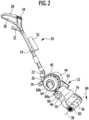
- FIG. 1 and 2An embodiment of a floor cleaning machine as it is in the Figures 1 and 2 shown in an overall view and designated there with 10, is a hand-guided and hand-held floor cleaning machine.
- Thiscomprises a carrier device 12.
- the carrier device 12is designed as a frame 14.
- This frame 14has a first frame rod 16 and a second frame rod 18.
- the second frame rod 18is oriented transversely and in particular perpendicularly to the first frame rod 16 and is fixed to the first frame rod 16.
- the first frame rod 16 and the second frame rod 18span a plane.
- An element 20is located on the first frame rod 16 and projects beyond this plane.
- the element 20holds a joint 22 on which a rod device 24 is located.
- the rod device 24comprises a single rod.
- the rod device 24is held on the support device 12 via the joint 22 so that it can pivot about a pivot axis 26.
- the pivot axis 26is at least approximately parallel to the first frame rod 16.
- the handle 28At one end of the rod device 24, which is opposite the end by which the rod device 24 is fixed to the joint 22, there is a handle 28.
- the handle 28comprises a closed bracket 30. It also comprises a grip element 32 at a distance from the bracket 30.
- One or more switches 34 for switching a cleaning operation of the floor cleaning machine 10 on or offare located on the handle 28.
- the rod device 24 with the handle 28forms a user holding unit, via which a user can hold and guide the floor cleaning machine 10.
- the rod device 24has such a length that a standing user of the floor cleaning machine 10, who is standing on the floor to be cleaned, can guide and operate the machine without having to bend down.
- the rod device 24is designed such that its length and in particular the distance of the handle 28 to the joint 22 is lockably adjustable. This makes it possible to adapt it to different users.
- a cleaning roller 36is located on the second joint rod 18 in the area of a front end of the carrier device 12.
- the cleaning roller 36can be driven to rotate about a rotation axis 38.
- a driveis provided which is positioned in an interior of the cleaning roller 36.
- the rotation axis 38is in particular parallel to the pivot axis 26.
- a blower device 40is also located on the carrier device 12.
- the blower device 40generates a suction flow.
- a suction channel device 42is arranged on the carrier device 12 between the blower device 40 in the cleaning roller 36.
- the suction channel device 24provides a fluid-effective connection between the cleaning roller 36 and the blower device 40 in order to be able to discharge the suction flow generated by the blower device 40 away from the cleaning roller 36.
- the blower device 40is assigned a drive 44 and in particular an electric motor drive 44. This is also positioned on the carrier device 12.
- the blower device 40is assigned a separator device 46, by means of which an air portion can be separated from a residual portion (liquid with dirt particles) in the suction flow.
- the separator device 46is connected upstream of the blower device 40 in the suction flow. It is positioned in particular on the suction channel device 42.
- the separator device 46is in turn associated with a dirty liquid container 48 in which dirty liquid can be collected.
- the Dirty liquid container 48is in particular arranged removably on the carrier device 12 and in particular the suction channel device 42, so that it can be emptied and/or cleaned in a simple manner.
- the floor cleaning machine 10comprises a cleaning liquid container 52.
- the cleaning liquid container 52is arranged on the rod device 24 and is arranged in a removable manner, in particular for refilling.
- One or more liquid lines 53lead from the cleaning container 52 to the cleaning roller 36.
- the suction channel device 42is the "mediating" unit between the blower device 40 and the cleaning roller 36.
- the suction flowis passed through it in order to carry out a separation in the separator device 46 and to separate an air portion from a residual portion.
- the suction flowbasically contains air as a "carrier medium", with the corresponding negative pressure flow being produced by the blower device 40, and a liquid portion and a solid portion.
- the cleaning roller 36is moistened using cleaning liquid (in particular water, possibly with additives) from the cleaning container 52, as will be explained in more detail below. This allows cleaning liquid to be applied to the floor 50 to be cleaned and dirt adhering to the floor can be softened. Liquid and dissolved dirt or undissolved dirt particles are sucked in and fed through the suction channel device 42 to the separator device 46.
- the cleaning roller 36comprises (see for example Figure 9 ) a hollow roller 54 with an interior 56. On the hollow roller 54 there is a trimming 58, in particular made of a textile material.
- the cleaning roller 36is moistened internally.
- Cleaning fluidis supplied to the interior 56 of the hollow roller 44 via the line 53.
- the hollow roller 54is provided with corresponding openings to the trimmings 58. This allows cleaning fluid to escape and moisten the trimmings 58 and in turn be applied to the floor 50.
- the cleaning roller 52can be placed and in particular pushed onto a rotating shaft which is located on the carrier device 12 via the hollow roller 54 with the interior 56.
- the cleaning roller 36can be fixed to this shaft in a rotationally fixed manner.
- the suction channel device 42comprises at least one suction channel 60 (cf. Figure 9 ). This suction channel 60 is arranged in the suction channel device 42 and leads from the cleaning roller 36 to the blower device 40.
- the blower device 40 with drive 44is firmly attached to the carrier device 12 and in particular to the first frame rod 16.
- a drive 62 for the cleaning roller 36is firmly fixed to the second articulated rod 18.
- a gear for transmitting torque to the shaft for the cleaning roller 36is arranged in the second articulated rod 18.
- the drive 62 and the blower device 40 with drive motor 44form a unit which is firmly attached to the carrier device 12.
- a pipe 64leads from a connection 66 on the suction duct device 42 to a corresponding connection of the blower device 40.
- Pipe bends 68a and 68bare located on the pipe 64.
- the pipe 64 and the pipe bends 68a, 68bare arranged outside the suction channel device 42 and the blower device 40. They are arranged, for example, on a side opposite the drive 62.
- the suction channel device 42is designed as a housing 70.
- the at least one suction channel 60can be arranged in a protected manner in this housing 70.
- the dirty liquid container 48 and the separator device 46can be positioned in a protected manner in the housing.
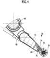
- the suction channel 60has an opening 72 (see, for example, the Figures 4 and 9 ) which is open towards the cleaning roller 36.
- the cleaning roller 36is suctioned off on an outside via this mouth 72 and the suction flow is coupled into the suction channel 60 and thus into the suction channel device 42.
- the mouth 72comprises a first mouth wall 74 and a second mouth wall 76.
- a mouth opening 78is formed between the first mouth wall 74 and the second mouth wall 76.
- the first mouth wall 74is an upper mouth wall with respect to the second mouth wall 76.
- first mouth wall 74 and the second mouth wall 76there are spaced transverse walls 75a, 75b.
- the first mouth wall 74has a front side 80a.
- the second mouth wallhas a front side 80b (cf. Figure 9 ).
- the end faces 80a and 80bare at least approximately straight and parallel to one another. In particular, the end faces 80a and 80b are parallel to the axis of rotation 38.
- the mouth opening 78has a rectangular cross-section and preferably extends over the entire length of the cleaning roller 36, on which a trim 58 is arranged.
- a height of the mouth opening 78(the distance between the first mouth wall 74 and the second mouth wall 76 at the mouth opening 78) is smaller than a diameter of the cleaning roller 36 and is, for example, at most 10% of the diameter of the cleaning roller 36.
- the mouth opening 78is arranged in a fourth quadrant 82 with respect to the cleaning roller 36 when the floor cleaning machine 10 is placed on the floor 50 in an operative mode and is supported by the cleaning roller 36 and a coordinate system is defined accordingly, which has axes parallel and perpendicular to the floor 50 and in which the center runs through the point of intersection of the axis of rotation 38.
- the first mouth wall 74rests against the trim 58 of the cleaning roller 36 or projects into it. In the Figures 3 and 9 an embodiment is shown in which the first mouth wall 74 projects into the trim 58.
- the front side 80a of the first mouth wall 74lies on the trim 58 or is immersed in the trim 58 ( Figures 4 and 9 ).
- the second mouth wall 76rests against the trim 58; the front side 80b touches the trim 58 without protruding into it.
- the mouth opening 78it is also possible as an alternative for the mouth opening 78 to be set back with respect to the front side 80b opposite the cleaning roller 36 with the trim 58, i.e. that the front side 80b is spaced apart from the trim 58 or protrudes into the trim 58.
- the suction channel 60leads from the mouth 72 to the connection 66.
- a contact element 200is arranged at the mouth 72. In one embodiment, this contact element 200 is arranged on the first mouth wall 74, whereby a fluid tightness is established between the first mouth wall 74 and the contact element 200. The contact element 200 points transversely away from the first mouth wall 74.
- the contact element 200projects into the trim 58 of the cleaning roller 36. It dips into the trim 58 with a lower region.
- the immersion areais a partial area of the system element 200.
- a contour 202 of the contact element 200is adapted to the cleaning roller 36.
- the contour 202which faces the cleaning roller 36, is curved with the same curvature as the cleaning roller 36.
- the contact element 200ensures improved fluid coupling into the orifice 72.
- a contact element 204is provided which sits on the first mouth wall 74 and projects transversely away from it.
- This contact element 204has a first end 206 which is spaced apart from the first mouth wall 74. It also has a second end 208 which lies on the mouth 72 and thus on the mouth wall 74.
- the contact element 204extends between the first end 206 and the second end 208.
- the contact element 204is not uniformly high (in cross-section) between the first end 206 and the second end 208. It has a first region 210, at which the first end 206 is located. This first region 210 merges into a second region 212 and in particular is continuous , with the second end 208 lying in the second region 212.
- An underside 214 of the contact element 204has a greater distance from the rotation axis 38 of the cleaning roller 36 in the first region 210 than in the second region 212.
- the contact element 200 or the contact element 204have a length (between the first end 206 and the second end 208) which is greater than a corresponding opening length of the mouth 72.
- a contact element 216is arranged on the first mouth wall 74. This is completely immersed in the trim 58 of the cleaning roller 36.
- This contact element 216has a first region 220 at a first end 218 and a second end 222 at the first mouth wall 74, which is formed in a second region 224. In the first region 220, the contact element 216 facing the cleaning roller 36 has a greater distance from the axis of rotation 38 than in the second region 224.
- both the first region 220 and the second region 224are completely immersed in the trimming 58.
- the suction channel 60tapers in one area towards the separator device 46. This forms a type of funnel 83 on the separator device 46 in order to obtain effective suction over the entire length of the cleaning roller 36 and to increase the flow speed for entry into the separator device.
- the cleaning roller 36is driven in a rotating manner with a direction of rotation 84.
- the rotation of the cleaning roller 36 and the operation of the blower device 40are switched simultaneously via the switch 34.
- the corresponding drive 62 for the rotation of the cleaning roller 36 and the drive 44receive their drive energy, for example, from a rechargeable battery device, which is arranged, for example, in the housing 70 of the suction channel device 42 (not shown in the figures), or from mains power.
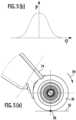
- the direction of rotation 84is such that a contact line 86 ( Figure 5(a) ) of the cleaning roller 36 on the base 50 rotates away from the base 50 towards the mouth 72.
- the direction of rotation 84is such that, with respect to this, the second mouth wall 76 lies in front of the first mouth wall 74.
- the direction of rotation 84, when the cleaning roller 36 is placed on the floor 50 during proper operation,is a clockwise rotation for a user standing on the floor 50.
- the direction of rotationis opposite to the direction of rotation 84, i.e. the rotation is counterclockwise
- the second mouth wall 76rests against the trim 58 or protrudes into it.
- the first mouth wall 74can then rest against the trim 58, be spaced from it or protrude into it.
- dirtis picked up, the cleaning roller 36 then rotates from the second quadrant into the first quadrant and from there into the fourth quadrant and the suction takes place at the mouth 72.
- a rotation speed of the cleaning roller 36is in particular in the range between approximately 200 revolutions per minute and 400 revolutions per minute.
- the contact weight on the cleaning roller 36is, for example, in the order of approximately 6 kg.
- FIG 5(b)The diagram shows the course of a contact force for a cleaning roller 36 with textile trimming 58 as a function of a rotational position.
- the angle of rotation 0refers to the line 86 as shown in Figure 5(a) is shown. At the angle of rotation 0, it touches the floor 50. This is where the greatest contact pressure is present. This causes a large line pressure and thus the highest water concentration. Dirt on the floor 50 is softened accordingly. If the cleaning roller 36 is rotated further, the contact pressure and thus also the water concentration decreases. The floor 50 can then be dried further by the cleaning roller 36.
- the suction channel device 42 with the mouth 72is connected via an elastic device 90 ( Figure 6 ) is pressed against the cleaning roller 36 and is thus kept pre-tensioned.
- Figure 6This is shown schematically.
- the elastic Device 90is supported on the carrier device 12 via a first side 92 and on the separator device 46 via a second side 94.
- the separator device 46 and the suction channel device 42form a unit.
- the separator device 46 and the suction channel device 42are directly connected to one another. As a result, the suction channel device 42 is then pressed against the cleaning roller 36 by the elastic device 90, supported on the carrier device 12.
- the elastic device 90is formed by a spring device, for example with one or more spiral springs or spiral springs.
- the corresponding elastic device 90is supported on the blower device 40.
- the separator device 46 and the suction channel device 42are separated.
- the elastic device 90 with one or more springsis supported on the blower device 40 via the first side 92. It is supported on the separator device 46 via the second side 94 and presses it in the direction of the cleaning roller 36 via a corresponding preload.
- the separator device 46 and the suction channel device 42are connected to one another, although the connection is not direct, but rather a frictional connection. The separator device 46 therefore acts with a corresponding contact force on the suction channel device 42 and presses it onto the cleaning roller 36.
- the elastic device 90is supported on the carrier device 12 (or the blower device 40 or the separator device 46) via the first side 92 and is supported directly on the suction channel device 42 via the second side 94 and presses it directly against the cleaning roller 36 in order to generate the corresponding pre-tension.
- the cleaning roller 36is assigned (at least) one sweeping lip 96.
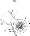
- the sweeping lip 96is seated in a holder 98 ( Figures 9 and 10 , the sweeping lip is not shown in these figures.)
- the floor cleaning machine 10has a front end 100 on the cleaning roller 36.
- the sweeping lip 96is arranged behind the cleaning roller 36 with respect to this front end 100. It is fixed to an underside of the suction channel device 42.
- the sweeping lip 96closes off a space 102 between a bottom side 104 of the suction channel device 42, which is opposite the first mouth wall 74, and the cleaning roller 36.
- a normal operating mode of the floor cleaning machine 10is that it is pushed, i.e. pushed forward.
- the corresponding directionis shown in Figure 1 shown by the arrow with the reference number 106.
- the sweeping lip 96is designed in such a way that it rests on the floor 50 and coarse dirt is "swept up" in the process. This coarse dirt in a space 108 between the sweeping lip 96 and the cleaning roller 36 is taken along by the cleaning roller 36 with its direction of rotation 84 and fed to the mouth 72 and can be sucked off there. Coarse dirt can also be sucked off by the sweeping lip 96.
- the sweeping lip 96is in particular arranged to be movable and/or designed to be movable. This is shown in Figure 11 indicated by the arrow with the reference number 110.
- the movable designis achieved, for example, by a rubber design with a correspondingly elastic rubber material.
- the sweeping lip 96can also be arranged so as to be movable, for example pivotable, and in particular can be arranged so as to be movable on the suction channel device 42.
- the sweeping lip 96is then made of a corresponding hard rubber material.
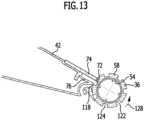
- the floor cleaning machine 10has an air supply device 112 (see Figures 9 and 10 ).
- the air supply device 112provides additional air supply to the cleaning roller 36 at or near the mouth 72 in order to enable optimized suction.
- the supply air devicecomprises (at least) one channel 114, which is arranged in the extraction channel device 42.
- This channel 114has an inlet-side opening 116 for coupling in supply air and an outlet-side opening 118 for coupling out supply air which was coupled in via the inlet-side opening 116.
- the inlet-side opening 118is arranged on the underside 104 of the suction channel device 42 at a distance from the cleaning roller 36.
- the outlet-side opening 118points towards the cleaning roller 36.
- the outlet-side opening 118is arranged in front of the opening 72.
- the outlet-side orifice 118is arranged in particular in the fourth quadrant 82. It is located near the orifice 72.
- the end face 80b of the second mouth wall 76also forms an end face of a wall in which an orifice opening of the outlet-side mouth 118 is located.
- Supply aircan then be coupled from the room 102 and fed to the cleaning roller 36.
- the supply air device 112has (at least) one channel 120, which is connected on the inlet side to a corresponding opening (in Figure 10 not shown) is coupled to the blower device 40.
- cooling air or exhaust air of the blower device 40is used as supply air and then fed by the blower device 40 through the channel 120 to the cleaning roller 36.
- the channel 120then runs in particular along the suction channel device 42.
- An outlet-side orifice 118is basically arranged as described above in the embodiment according to Figure 9 described.
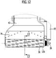
- the cleaning roller 36is provided with grooves 122.
- a grooveis formed in the trim 58.
- a groove 122is formed, for example, by being a recess in the trim 58, at which no trim is arranged or at which a height of the trim 58 above the hollow roller 54 is lower than outside the corresponding groove 122.
- the grooveis shown with a rectangular cross-section.
- the corresponding groove as a recess in the trim 58can also have a different shape. For example, it can have a circular cross-section or another cross-sectional shape.
- Such a groove 122then has a space 124.
- the cleaning roller 36has a plurality of grooves 122 which are spaced apart in an axial direction 126 (which is parallel to the axis of rotation 38) and spaced apart in the circumferential direction 128.
- the cleaning roller 36is structured by the grooves 122. When the cleaning roller 36 rotates, a short air pulse is generated at the individual grooves 122 as the suction flow passes through the mouth 72. This air pulse can carry away dirt that has become caught in the trim 58.
- the grooves 122are evenly distributed on the cleaning roller 36 with respect to the circumferential direction 128 and the axial direction 126 in order to to largely prevent dead zones with regard to the entrainment of contaminants.
- a length of a groove 122 in the axial direction 126is at most 10% of the length of the cleaning roller 36 with trimming 58 in this axial direction 126.
- a width of a groove 122 in the circumferential direction 128amounts to at most 5% of a total circumference of the cleaning roller 36 on a surface of the facing 58.
- the floor cleaning machine 10When the floor cleaning machine 10 is in operation, it is only supported on the cleaning roller 36.
- the floor cleaning machine 10is designed without support wheels. This prevents abrasion marks caused by support wheels.
- the floor cleaning machine 10works as follows: The floor cleaning machine 10 is operated during a cleaning process in such a way that a rotation of the cleaning roller 36 in the direction of rotation 84 is driven by a corresponding drive.
- the blower device 40ensures a corresponding negative pressure to provide a suction flow.
- the cleaning roller 36is moistened from the inside with cleaning fluid from the cleaning fluid container 52, whereby the trimmings 58 are moistened. Suction takes place at the mouth 72 through the suction channel device 42 on an outside of the cleaning roller 36.
- the rotational speed of the cleaning roller 36is set such that the throwing off of water droplets from the cleaning roller 36 is largely prevented.
- the direction of rotation 84is preferably directed towards an operator who holds the floor cleaning machine 10 on the user holding unit. This allows normal operation, in which cleaning is carried out from a room to be cleaned, to be carried out effectively.
- the suction channel device 42 with the mouth 72is pressed against the cleaning roller 36 by the elastic device 90 and in particular by spring force so that effective suction takes place.
- the first mouth wall 74rests against the trimmings 58 or penetrates into it.
- the sweeping lip 96provides a sweeping function for particles that are not directly taken away by the cleaning roller 36.
- the cleaning roller 36is a wiping roller.
- the sweeping lip 96ensures that coarse dirt also reaches the mouth 72 by being taken along by the cleaning roller 36.
- the air supply to the outlet 72is hindered.
- the air supply device 112ensures a sufficient air supply. Air can then be supplied from the environment or process exhaust air or blower device exhaust air can be supplied. This in turn enables good coarse dirt collection with sufficient residual moisture value.
- the cleaning roller 36rests on the floor 50.
- the highest contact pressureprevails at a contact line and the largest amount of cleaning fluid is provided there, which in turn can soften dirt on the floor 50.
- the contact pressure outside of this contact line 86is correspondingly lower and the cleaning fluid concentration is then also lower.
- the floor 50can then be dried further via the cleaning roller 36.
- the entire weight of the devicerests on the cleaning roller 36.
- the cleaning roller 36is structured via the grooves 122. As a result, short air pulses are generated when the suction flow passes through the mouth 72 in order to be able to carry away dirt that has become caught on the trim 58.
Landscapes
- Engineering & Computer Science (AREA)
- Mechanical Engineering (AREA)
- Cleaning In General (AREA)
- Nozzles For Electric Vacuum Cleaners (AREA)
Description
Translated fromGermanDie Erfindung betrifft eine Bodenreinigungsmaschine, welche handgeführt und/oder handgehalten ist, umfassend eine Trägereinrichtung, mindestens eine Reinigungswalze, welche an der Trägereinrichtung angeordnet ist, rotierend antreibbar ist und mit einem Besatz versehen ist, eine Gebläseeinrichtung zur Erzeugung eines Saugstroms, und eine Absaugkanaleinrichtung für den Saugstrom, welche mindestens einen Absaugkanal mit einer fluidwirksamen Verbindung zwischen der Gebläseeinrichtung und der mindestens einen Reinigungswalze bereitstellt, wobei der mindestens eine Absaugkanal mindestens eine Mündung zu der mindestens einen Reinigungswalze hin aufweist und die mindestens eine Mündung eine erste Mündungswandung und eine beabstandete zweite Mündungswandung aufweist, zwischen welchen eine Mündungsöffnung gebildet ist, wobei bei auf einem zu reinigenden Boden aufgesetzter mindestens einer Reinigungswalze die erste Mündungswandung bezogen auf die Schwerkraftrichtung oberhalb der zweiten Mündungswandung positioniert ist.The invention relates to a floor cleaning machine which is hand-guided and/or hand-held, comprising a carrier device, at least one cleaning roller which is arranged on the carrier device, can be driven in rotation and is provided with a trim, a blower device for generating a suction flow, and a suction channel device for the suction flow, which provides at least one suction channel with a fluid-effective connection between the blower device and the at least one cleaning roller, wherein the at least one suction channel has at least one mouth towards the at least one cleaning roller and the at least one mouth has a first mouth wall and a spaced-apart second mouth wall, between which a mouth opening is formed, wherein when at least one cleaning roller is placed on a floor to be cleaned, the first mouth wall is positioned above the second mouth wall with respect to the direction of gravity.
Aus der
Aus der
Aus der
Aus der
Aus der
Aus der
Der Erfindung liegt die Aufgabe zugrunde, eine Bodenreinigungsmaschine der eingangs genannten Art bereitzustellen, welche bei einfacher Handhabbarkeit ein optimiertes Reinigungsergebnis liefert.The invention is based on the object of providing a floor cleaning machine of the type mentioned above, which delivers an optimized cleaning result while being easy to handle.
Diese Aufgabe wird erfindungsgemäß dadurch gelöst, dass bei der Bodenreinigungsmaschine der eingangs genannten Art die erste Mündungswandung und/oder die zweite Mündungswandung an dem Besatz der mindestens einen Reinigungswalze anliegt oder in diesen hineinragt, und dass an der Absaugkanaleinrichtung mindestens eine Kehrlippe angeordnet ist.This object is achieved according to the invention in that, in the floor cleaning machine of the type mentioned at the outset, the first mouth wall and/or the second mouth wall rests on the trim of the at least one cleaning roller or projects into it, and in that at least one sweeping lip is arranged on the suction channel device.
Dadurch, dass mindestens eine Mündungswandung an dem Besatz der mindestens einen Reinigungswalze anliegt oder in diesen hineinragt (das heißt in diesen eintaucht), ergibt sich ein optimiertes Saugergebnis. An der mindestens einen Mündung, an welcher eine Unterdruckbeaufschlagung erfolgt, das heißt ein Saugstrom erzeugt wird, wird die mindestens eine Reinigungswalze vorbeigeführt und Verschmutzungen lassen sich einsaugen.The fact that at least one outlet wall rests against the trim of the at least one cleaning roller or protrudes into it (i.e. dips into it) results in an optimized suction result. The at least one cleaning roller is guided past the at least one outlet, at which a negative pressure is applied, i.e. a suction flow is generated, and dirt can be sucked in.
Insbesondere ist eine Stirnseite der ersten Mündungswandung und/oder eine Stirnseite der zweiten Mündungswandung mindestens näherungsweise parallel zu einer Rotationsachse der mindestens einen Reinigungswalze. Dadurch ergibt sich eine effektive Absaugung. Es lässt sich eine Wischfunktion mit Absaugung realisieren.In particular, a front side of the first mouth wall and/or a front side of the second mouth wall is at least approximately parallel to a rotation axis of the at least one cleaning roller. This results in effective suction. A wiping function with suction can be implemented.
Grundsätzlich kann die erste Mündungswandung an dem Besatz anliegen oder in diesen hineinragen und die zweite Mündungswandung an dem Besatz der mindestens einen Reinigungswalze anliegen oder beabstandet zu diesem sein oder in diesen hineinragen beziehungsweise, wenn die zweite Mündungswandung an dem Besatz anliegt oder in diesen hineinragt, kann die erste Mündungswandung an dem Besatz anliegen oder in diesen hineinragen, oder beabstandet sein. Insbesondere liegt die erste Mündungswandung an dem Besatz an oder ragt in diesen hinein und eine Drehrichtung der mindestens einen Reinigungswalze ist derart, dass zuerst ein bestimmter Punkt der mindestens einen Reinigungswalze an der zweiten Mündungswandung vorbeigeführt wird und anschließend an der ersten Mündungswandung. Wenn die zweite Mündungswandung an dem Besatz anliegt oder in diesen hineinragt, ist insbesondere eine Drehrichtung derart, dass ein bestimmter Punkt der mindestens einen Reinigungswalze zuerst an der erste Mündungswandung vorbeigeführt wird und dann an der zweiten Mündungswandung.In principle, the first mouth wall can rest against the trim or protrude into it and the second mouth wall can rest against the trim of the at least one cleaning roller or be spaced apart from it or protrude into it or, if the second mouth wall rests against the trim or protrudes into it, the first mouth wall can rest against the trim or protrude into it or be spaced apart. In particular, the first mouth wall rests against the trim or protrudes into it and a direction of rotation of the at least one cleaning roller is such that first a certain point of the at least one cleaning roller is guided past the second mouth wall and then past the first mouth wall. If the second mouth wall rests against the trim or protrudes into it, a direction of rotation is in particular such that a certain point of the at least one cleaning roller is guided past the first mouth wall and then past the second mouth wall.
Bei einem Ausführungsbeispiel ist an der Mündung ein Anlageelement angeordnet, welches an dem Besatz anliegt oder in diesen hineinragt, und welches von der ersten Mündungswandung oder der zweiten Mündungswandung quer weg ragt, wobei eine Fluiddichtung zwischen dem Anlageelement und der entsprechenden Mündungswand vorliegt. Durch das Anlageelement wird der Bereich des Anliegens beziehungsweise Hineinragens in den Besatz vergrößert und es wird eine höhere Fluiddichtigkeit erzielt, wobei wiederum die Absaugung verbessert wird. Das Anlageelement bildet (im Querschnitt) eine Art von Schnabel, welches von der ersten Mündungswandung beziehungsweise der zweiten Mündungswandung weg ragt. Die mindestens eine Reinigungswalze ist bei der Rotation an dem Anlageelement vorbeigeführt.In one embodiment, a contact element is arranged on the mouth, which rests on the trimmings or projects into them, and which projects transversely away from the first mouth wall or the second mouth wall, with a fluid seal between the contact element and the corresponding mouth wall. The contact element increases the area of contact or projection into the trimmings and a higher fluid tightness is achieved, which in turn improves the suction. The contact element forms (in cross section) a type of beak, which projects away from the first mouth wall or the second mouth wall. The at least one cleaning roller is guided past the contact element during rotation.
Bei einem Ausführungsbeispiel sitzt das Anlageelement an der ersten Mündungswandung. Es lässt sich dadurch auf einfache Weise ein verbesserter Absaugeffekt erzielen. Eine Fluiddichtigkeit zwischen Anlageelement und Mündung lässt sich auf einfache Weise realisieren.In one embodiment, the contact element is located on the first mouth wall. This makes it easy to achieve an improved Achieve a suction effect. A fluid tightness between the contact element and the mouth can be achieved in a simple manner.
Günstig ist es, wenn das Anlageelement der mindestens einen Reinigungswalze zugewandt eine gekrümmte Kontur aufweist, welche an die mindestens eine Reinigungswalze angepasst ist. Insbesondere hat die Kontur mindestens bezüglich einer Einhüllenden eine an eine entsprechende Kreiskontur der mindestens einen Reinigungswalze angepasste Kreiskontur. Dadurch ist der Reibungswiderstand durch Vorbeidrehen der mindestens einen Reinigungswalze an dem Anlageelement minimiert.It is advantageous if the contact element facing the at least one cleaning roller has a curved contour which is adapted to the at least one cleaning roller. In particular, the contour has a circular contour adapted to a corresponding circular contour of the at least one cleaning roller at least with respect to an envelope. This minimizes the frictional resistance caused by the at least one cleaning roller rotating past the contact element.
Das Anlageelement weist ein erstes Ende auf, welches beabstandet zu der Mündung ist, und weist ein zweites Ende auf, welches an der Mündung positioniert ist, wobei das Anlageelement günstigerweise so ausgebildet ist, dass ein entstehender Unterdruck an dem ersten Ende kleiner ist als an dem zweiten Ende. Es wird dadurch die Gefahr eines "Fluid-Kurzschlusses" verringert, über den Fluid und insbesondere Flüssigkeit im Bereich des ersten Endes herausgesogen werden könnte. Es wird dadurch das Reinigungsergebnis verbessert.The contact element has a first end which is spaced from the mouth and has a second end which is positioned at the mouth, wherein the contact element is advantageously designed such that a negative pressure that arises at the first end is smaller than at the second end. This reduces the risk of a "fluid short circuit" through which fluid and in particular liquid could be sucked out in the area of the first end. This improves the cleaning result.
Beispielsweise kann eine Ausbildung zur Verringerung des entstehenden Unterdrucks an dem ersten Ende im Vergleich zu dem zweiten Ende so sein, dass das Anlageelement genügend lang gemacht wird, wobei dann eine erhöhte Reibungsfläche bereitgestellt ist. Bei einem Ausführungsbeispiel hat das Anlageelement einen ersten Bereich mit dem ersten Ende und einen zweiten Bereich mit dem zweiten Ende, wobei ein Abstand des Anlageelements an dem ersten Bereich zu einer Rotationsachse der mindestens einen Reinigungswalze größer ist als am zweiten Bereich. Dadurch lässt sich der entstehende Unterdruck im Bereich des ersten Endes im Vergleich zu dem Bereich am zweiten Ende reduzieren und die Gefahr eines Flüssigkeits-Kurzschlusses wird verringert. Diese Ausbildung lässt sich auf einfache Weise durch eine entsprechende Oberflächenausgestaltung des Anlageelements der mindestens einen Reinigungswalze zugewandt erreichen. Beispielsweise ist das Anlageelement an der entsprechenden Oberfläche stufenförmig ausgebildet, wobei insbesondere die Stufe einen glatten Verlauf hat (ohne scharfe Kanten).For example, a design for reducing the negative pressure that develops at the first end compared to the second end can be such that the contact element is made sufficiently long, whereby an increased friction surface is then provided. In one embodiment, the contact element has a first region with the first end and a second region with the second end, whereby a distance of the contact element at the first region to a rotation axis of the at least one cleaning roller is greater than at the second region. This allows the negative pressure that develops in the region of the first end to be reduced compared to the region at the second end and the risk of a liquid short circuit is reduced. This design can be achieved in a simple manner by a corresponding surface design of the contact element facing the at least one cleaning roller. For example, the contact element is formed in steps on the corresponding surface, whereby the step in particular has a smooth course (without sharp edges).
Günstig ist es, wenn die zweite Mündungswandung bezogen auf eine Rotationsrichtung der mindestens einen Reinigungswalze vor der ersten Mündungswandung angeordnet ist. Ein bestimmter Bereich an der Reinigungswalze wird dann bei Rotation der Reinigungswalze zunächst an der zweiten Mündungswandung und dann an der ersten Mündungswandung vorbeigeführt. Es ergibt sich dadurch eine effektive Absaugung bei einfacher Bedienbarkeit. Bei dieser Ausführungsform ergibt sich ein kurzer Weg zur Zuführung von an dem Besatz anhaftenden Schmutzpartikeln zu der Mündung. Darüber hinaus ist diese Rotationsrichtung vorteilhaft, wenn mit der entsprechenden Bodenreinigungsmaschine aus einem Raum herausgereinigt wird.It is advantageous if the second mouth wall is arranged in front of the first mouth wall in relation to a direction of rotation of the at least one cleaning roller. A certain area on the cleaning roller is then guided past the second mouth wall and then the first mouth wall when the cleaning roller rotates. This results in effective suction and ease of use. This embodiment results in a short path for supplying dirt particles adhering to the trim to the mouth. In addition, this direction of rotation is advantageous when cleaning from a room using the corresponding floor cleaning machine.
Bei einem Ausführungsbeispiel ist ein Abstand einer Stirnseite der ersten Mündungswandung zu einer Rotationsachse der mindestens einen Reinigungswalze kleiner als ein Abstand einer Stirnseite der zweiten Mündungswandung zu der Rotationsachse.In one embodiment, a distance between a front side of the first mouth wall and a rotation axis of the at least one cleaning roller is smaller than a distance between a front side of the second mouth wall and the rotation axis.
Günstig ist es, wenn die Mündungsöffnung der mindestens einen Mündung mindestens näherungsweise einen rechteckigen Querschnitt aufweist. Dadurch lässt sich über einen großen Bereich die Reinigungswalze von außen absaugen und es ergibt sich eine effektive Schmutzabsaugung.It is advantageous if the mouth opening of at least one mouth has at least an approximately rectangular cross-section. This allows the cleaning roller to be vacuumed from the outside over a large area and results in effective dirt extraction.
Es ist dann entsprechend günstig, wenn der mindestens eine Absaugkanal zu einer Abscheidereinrichtung hin sich verjüngend ausgebildet ist. Dadurch ist an dem Absaugkanal eine Art von Trichter angeordnet, um eine effektive Schmutzabsaugung von der Reinigungswalze her zu ermöglichen. Es lässt sich an der Mündung und im weiteren Verlauf des mindestens einen Absaugkanals bis zu der Verjüngung eine große Querschnittsfläche bereitstellen, was strömungstechnisch günstig ist. Durch die Verjüngung in der Nähe der Abscheidereinrichtung lässt sich die Strömungsgeschwindigkeit erhöhen.It is then correspondingly advantageous if the at least one suction channel is tapered towards a separator device. This means that a type of funnel is arranged on the suction channel in order to enable effective dirt extraction from the cleaning roller. A large cross-sectional area can be provided at the mouth and in the further course of the at least one suction channel up to the taper, which is advantageous in terms of flow. The taper near the separator device allows the flow speed to be increased.
Günstig ist es, wenn mindestens ein Reinigungsflüssigkeitsbehälter vorgesehen ist, welcher in fluidwirksamer Verbindung mit der mindestens einen Reinigungswalze steht, wobei an der mindestens einen Reinigungswalze insbesondere über einen Innenraum der mindestens einen Reinigungswalze Reinigungsflüssigkeit bereitgestellt ist. Es lässt sich dadurch die Reinigungswalze und insbesondere deren Besatz befeuchten und es lässt sich mit der Bodenreinigungsmaschine eine Wischfunktion realisieren. Über den Reinigungsflüssigkeitsbehälter wird entsprechende Reinigungsflüssigkeit bereitgestellt. Der Reinigungsflüssigkeitsbehälter ist dabei insbesondere abnehmbar an der Bodenreinigungsmaschine angeordnet.It is advantageous if at least one cleaning fluid container is provided, which is in fluid connection with the at least one cleaning roller, wherein cleaning fluid is provided on the at least one cleaning roller, in particular via an interior of the at least one cleaning roller. This allows the cleaning roller and in particular its trim to be moistened and a wiping function can be implemented with the floor cleaning machine. Appropriate cleaning fluid is provided via the cleaning fluid container. The cleaning fluid container is arranged on the floor cleaning machine in particular in a removable manner.
Bei einem Ausführungsbeispiel ist der mindestens eine Reinigungsflüssigkeitsbehälter an einer Benutzer-Halteeinheit angeordnet. Er lässt sich dadurch effektiv an der Bodenreinigungsmaschine positionieren und dabei bezüglich der Schwerkraftrichtung oberhalb der mindestens einen Reinigungswalze positionieren.In one embodiment, the at least one cleaning fluid container is arranged on a user holding unit. It can thus be effectively positioned on the floor cleaning machine and positioned above the at least one cleaning roller with respect to the direction of gravity.
Günstig ist es, wenn die Gebläseeinrichtung an der Trägereinrichtung angeordnet ist und/oder die Absaugkanaleinrichtung an der Trägereinrichtung angeordnet ist. Dadurch ergibt sich ein einfacher konstruktiver Aufbau.It is advantageous if the blower device is arranged on the support device and/or the suction channel device is arranged on the support device. This results in a simple structural design.
Bei einem Ausführungsbeispiel umfasst die Absaugkanaleinrichtung ein Gehäuse, in welchem der mindestens eine Absaugkanal angeordnet oder gebildet ist. Das Gehäuse kann beispielsweise dazu genutzt werden, um einen Schmutzflüssigkeitsbehälter und/oder eine Abscheidereinrichtung unterzubringen. Es kann beispielsweise auch dazu genutzt werden, um eine Batterieeinrichtung und insbesondere wiederaufladbare Batterieeinrichtung unterzubringen.In one embodiment, the suction channel device comprises a housing in which the at least one suction channel is arranged or formed. The housing can be used, for example, to accommodate a dirty liquid container and/or a separator device. It can also be used, for example, to accommodate a battery device and in particular a rechargeable battery device.
Günstig ist es, wenn eine elastische Einrichtung vorgesehen ist, durch welche die Absaugkanaleinrichtung elastisch gegen die mindestens eine Reinigungswalze gedrückt ist, wobei die elastische Einrichtung insbesondere eine Federeinrichtung ist oder umfasst. Es lässt sich dadurch auf einfache Weise erreichen, dass die erste und/oder zweite Mündungswandung an dem Besatz der mindestens einen Reinigungswalze anliegt oder in diesen hineingedrückt ist. Diese entsprechende Funktionalität ist auch bei einem Abrieb des Besatzes zumindest bis zu einer gewissen Schwelle sichergestellt.It is advantageous if an elastic device is provided by which the suction channel device is pressed elastically against the at least one cleaning roller, wherein the elastic device is or comprises in particular a spring device. This makes it easy to achieve that the first and/or second mouth wall rests against the trim of the at least one cleaning roller or is pressed into it. This corresponding functionality is ensured even if the trim is worn away, at least up to a certain threshold.
Bei einem Ausführungsbeispiel stützt sich die elastische Einrichtung über eine erste Seite an der Trägereinrichtung ab. Die Trägereinrichtung bildet dann eine Montagefläche für die elastische Einrichtung.In one embodiment, the elastic device is supported on the carrier device via a first side. The carrier device then forms a mounting surface for the elastic device.
Es ist auch möglich, dass die elastische Einrichtung sich über eine erste Seite an der Gebläseeinrichtung oder einer Abscheidereinrichtung abstützt. Die Gebläseeinrichtung oder Abscheidereinrichtung bildet dann eine Montagefläche für die elastische Einrichtung.It is also possible for the elastic device to be supported on a first side on the blower device or a separator device. The blower device or separator device then forms a mounting surface for the elastic device.
Bei einem Ausführungsbeispiel stützt sich die elastische Einrichtung über eine zweite Seite an der Absaugkanaleinrichtung ab. Es wird dadurch eine entsprechende Vorspannungskraft auf die Absaugkanaleinrichtung direkt ausgeübt, welche diese mit der ersten Mündungswandung gegen den Besatz drückt.In one embodiment, the elastic device is supported on the suction channel device via a second side. This exerts a corresponding pre-tensioning force directly on the suction channel device, which presses it with the first mouth wall against the trimmings.
Es ist auch möglich, dass die elastische Einrichtung sich über eine zweite Seite an der Gebläseeinrichtung oder der Abscheidereinrichtung abstützt, wobei die Gebläseeinrichtung oder die Abscheidereinrichtung mit der Absaugkanaleinrichtung verbunden ist, wobei die Verbindung eine direkte Verbindung oder Kraftschlussverbindung ist. Über die Gebläseeinrichtung oder die Abscheidereinrichtung wird dann also direkt oder über Kraftschluss die Absaugkanaleinrichtung gegen den Besatz gedrückt.It is also possible for the elastic device to be supported on a second side by the blower device or the separator device, whereby the blower device or the separator device is connected to the suction channel device, whereby the connection is a direct connection or a frictional connection. The suction channel device is then pressed against the trimmings directly or by frictional connection via the blower device or the separator device.
Günstig ist es, wenn ein Schmutzflüssigkeitsbehälter vorgesehen ist, welcher einer Abscheidereinrichtung zugeordnet ist. Dadurch lässt sich verschmutzte Reinigungsflüssigkeit aufsammeln. An einer Abscheidereinrichtung wird in einem Saugstrom Luft von flüssigen und festen Bestandteilen getrennt.It is advantageous if a dirty liquid container is provided which is associated with a separator device. This allows dirty cleaning liquid to be collected. At a separator device, air is separated from liquid and solid components in a suction stream.
Günstig ist es dabei, wenn der Schmutzflüssigkeitsbehälter an der Absaugkanaleinrichtung angeordnet ist. Dadurch ergibt sich ein kompakter Aufbau und Strömungswege lassen sich minimieren.It is advantageous if the dirty liquid container is arranged on the suction channel device. This results in a compact structure and flow paths can be minimized.
Es ist ferner günstig, wenn an der Trägereinrichtung eine Benutzer-Halteeinheit angeordnet ist, welche insbesondere an einem Gelenk schwenkbar angeordnet ist. Ein Bediener kann dann die Bodenreinigungsmaschine auf einfache Weise bedienen und beispielsweise auch einhändig bedienen. Er kann diese schieben oder ziehen und dabei auch unter Minimierung von Standortwechseln eine größere Bodenfläche bearbeiten.It is also advantageous if a user holding unit is arranged on the carrier device, which is arranged in particular so that it can pivot on a joint. An operator can then operate the floor cleaning machine in a simple manner and, for example, operate it with one hand. He can push or pull it and also work on a larger floor area while minimizing changes of location.
Beispielsweise ist eine Schwenkachse des Gelenks parallel zu einer Rotationsachse der mindestens einen Reinigungswalze. Dadurch ergibt sich eine einfache Bedienbarkeit.For example, a pivot axis of the joint is parallel to a rotation axis of the at least one cleaning roller. This results in easy operation.
Bei einem Ausführungsbeispiel umfasst die Benutzer-Halteeinheit eine Stabeinrichtung beispielsweise mit einem Stab, an welchem ein Handgriff sitzt. Dadurch ergibt sich ein kompakter Aufbau bei einfacher Bedienbarkeit.In one embodiment, the user holding unit comprises a rod device, for example with a rod on which a handle is located. This results in a compact structure with easy operation.
Es ist günstig, wenn bei einem Reinigungsvorgang sich die Bodenreinigungsmaschine nur über die mindestens eine Reinigungswalze an dem Boden abstützt und insbesondere gekennzeichnet ist durch eine stützräderfreie Ausbildung. Es ergibt sich dadurch ein kompakter Aufbau. Es lässt sich das gesamte Gewicht der Bodenreinigungsmaschine über die mindestens eine Reinigungswalze abstützen. Durch eine stützräderfreie Ausbildung werden Abriebstreifen an dem zu reinigenden Boden vermieden.It is advantageous if, during a cleaning process, the floor cleaning machine is only supported on the floor by the at least one cleaning roller and is particularly characterized by a design without support wheels. This results in a compact structure. The entire weight of the floor cleaning machine can be supported by the at least one cleaning roller. A design without support wheels prevents abrasion marks on the floor to be cleaned.
Es ist günstig, wenn eine Rotationsrichtung der mindestens einen Reinigungswalze von einer Berührungslinie mit dem zu reinigenden Boden auf die zweite Mündungswandung zu und dann auf die erste Mündungswandung zu ist und insbesondere die Rotationsrichtung im Uhrzeigersinn ist, wenn die mindestens eine Reinigungswalze auf dem Boden aufgesetzt ist. Es lässt sich dadurch ein effektiver Betrieb, bei dem die Bodenreinigungsmaschine aus einem zu reinigenden Raum herausgeführt wird, durchführen.It is advantageous if the direction of rotation of the at least one cleaning roller is from a line of contact with the floor to be cleaned towards the second mouth wall and then towards the first mouth wall and in particular the direction of rotation is clockwise when the at least one cleaning roller is placed on the floor. This allows a effective operation in which the floor cleaning machine is led out of a room to be cleaned.
Ganz besonders vorteilhaft ist es, wenn die mindestens eine Reinigungswalze mit Nuten zur Erzeugung von Luftpulsen in einem Saugstrom versehen ist. Durch Nuten und insbesondere beabstandete Nuten, welche durch die Mündung durchgedreht werden, an welcher der Saugstrom vorliegt, lassen sich kurze Luftpulse erzeugen. Über diese lässt sich Schmutz, welcher an dem Besatz und insbesondere textilen Besatz der Reinigungswalze angehaftet ist, mitreisen. Es lässt sich dadurch eine effektive Reinigungswirkung erzielen.It is particularly advantageous if the at least one cleaning roller is provided with grooves for generating air pulses in a suction flow. Short air pulses can be generated by means of grooves and in particular spaced grooves which are rotated through the mouth at which the suction flow is present. Dirt which has adhered to the trim and in particular textile trim of the cleaning roller can be carried along via these. This enables an effective cleaning effect to be achieved.
Eine Nut ist insbesondere durch einen besatzfreien oder besatzreduzierten Bereich gebildet, um entsprechende Luftpulse im Saugstrom bewirken zu können. Eine Nut kann grundsätzlich eine beliebige Form wie Schlitzform oder Zylinderform aufweisen.A groove is formed in particular by a region free of or with reduced amounts of debris in order to be able to cause corresponding air pulses in the suction flow. A groove can basically have any shape, such as a slot or a cylinder.
Insbesondere ist eine Mehrzahl von beabstandeten Nuten vorgesehen, welche in einer axialen Richtung der mindestens einen Reinigungswalze und einer Umfangsrichtung der mindestens einen Reinigungswalze beabstandet sind. Durch entsprechende Anordnung lassen sich dadurch Totbereiche an der mindestens einen Reinigungswalze verhindern und es erfolgt ein effektives Mitreißen von anhaftenden Schmutzpartikeln in Wesentlichen über eine gesamte effektive Oberfläche der mindestens einen Reinigungswalze. Eine Nut kann beispielsweise einen rechteckigen Querschnitt oder einen kreisförmigen Querschnitt aufweisen. Auch andere Nutformen sind möglich.In particular, a plurality of spaced grooves are provided, which are spaced apart in an axial direction of the at least one cleaning roller and a circumferential direction of the at least one cleaning roller. By means of a corresponding arrangement, dead areas on the at least one cleaning roller can be prevented and adhering dirt particles are effectively entrained essentially over the entire effective surface of the at least one cleaning roller. A groove can, for example, have a rectangular cross-section or a circular cross-section. Other groove shapes are also possible.
Beispielsweise weist eine Nut (insbesondere bei rechteckigem Querschnitt) eine Länge auf, die höchstens 10 % einer axialen Länge der mindestens einen Reinigungswalze beträgt.For example, a groove (particularly with a rectangular cross-section) has a length that is at most 10% of an axial length of the at least one cleaning roller.
Ferner ist es beispielsweise günstig, wenn eine Nut (insbesondere bei rechteckigem Querschnitt) eine Breite aufweist, die höchstens 5 % einer Umfangslänge der mindestens einen Reinigungswalze beträgt.Furthermore, it is advantageous, for example, if a groove (particularly in the case of a rectangular cross-section) has a width which is at most 5% of a circumferential length of the at least one cleaning roller.
An der Absaugkanaleinrichtung ist mindestens eine Kehrlippe angeordnet. über die mindestens eine Kehrlippe lässt sich zusätzlich zu der Wischfunktion der Bodenreinigungsmaschine eine Kehrfunktion realisieren. Durch Anordnung an der Absaugkanaleinrichtung lässt sich beispielsweise Grobschmutz auf dem Boden, welcher über die Wischfunktion der mindestens einen Reinigungswalze nicht direkt erfassen lässt, in einem Bereich zwischen der mindestens einen Kehrlippe und der mindestens einen Reinigungswalze durch die mindestens eine Reinigungswalze mitnehmen und der Mündung mit dem Saugstrom zuführen.At least one sweeping lip is arranged on the suction channel device. The at least one sweeping lip can be used to implement a sweeping function in addition to the wiping function of the floor cleaning machine. By arranging it on the suction channel device, coarse dirt on the floor, for example, which cannot be directly picked up by the wiping function of the at least one cleaning roller, can be taken along by the at least one cleaning roller in an area between the at least one sweeping lip and the at least one cleaning roller and fed to the outlet with the suction flow.
Insbesondere ist dann die mindestens eine Kehrlippe so angeordnet und ausgebildet, dass Grobschmutz zwischen der mindestens einen Kehrlippe und der mindestens einen Reinigungswalze durch die mindestens eine Reinigungswalze mitgenommen wird und der mindestens einen Mündung zugeführt wird. Es lässt sich dadurch zusätzlich noch Grobschmutz absaugen.In particular, the at least one sweeping lip is arranged and designed in such a way that coarse dirt between the at least one sweeping lip and the at least one cleaning roller is taken along by the at least one cleaning roller and fed to the at least one opening. This also allows coarse dirt to be vacuumed away.
Günstigerweise trennt die mindestens eine Kehrlippe einen Raum hinter der mindestens einen Reinigungswalze und unterhalb der Absaugkanaleinrichtung zu dem zu reinigenden Boden hin von der mindestens einen Reinigungswalze, wenn die mindestens eine Reinigungswalze auf dem Boden aufgesetzt ist. Es lässt sich dadurch eine Kehrfunktion realisieren und Grobschmutz mitnehmen und abführen.Advantageously, the at least one sweeping lip separates a space behind the at least one cleaning roller and below the suction channel device towards the floor to be cleaned from the at least one cleaning roller when the at least one cleaning roller is placed on the floor. This allows a sweeping function to be implemented and coarse dirt to be taken along and removed.
Günstig ist es, wenn die mindestens eine Kehrlippe beweglich angeordnet ist und/oder ausgebildet ist und insbesondere elastisch ausgebildet ist. Dadurch lässt sie sich effektiv auf den zu reinigenden Boden aufsetzen, um Grobschmutz mitzunehmen.It is advantageous if the at least one sweeping lip is arranged and/or designed to be movable and, in particular, is designed to be elastic. This allows it to be placed effectively on the floor to be cleaned in order to remove coarse dirt.
Es ist besonders günstig, wenn eine Zulufteinrichtung vorgesehen ist, durch welche der mindestens einen Reinigungswalze Zuluft bereitgestellt ist. Insbesondere wenn eine Kehrlippe vorhanden ist, kann die Saugleistung aufgrund mangelnder Luftzuführung zu der Mündung nicht mehr ausreichend sein.It is particularly advantageous if an air supply device is provided, through which air is provided to the at least one cleaning roller. In particular, if a sweeping lip is present, the suction power may no longer be sufficient due to insufficient air supply to the mouth.
Durch die Zulufteinrichtung wird sichergestellt, dass eine ausreichende Zuluftzuführung vorhanden ist, um auch bei vorhandener Kehrlippe eine effektive Absaugung zu ermöglichen.The air supply device ensures that there is sufficient air supply to enable effective extraction even when a sweeping lip is present.
Die Zulufteinrichtung umfasst mindestens einen Kanal mit einer ausgangsseitigen Mündung für Zuluft, welche auf die mindestens eine Reinigungswalze hin ausgerichtet ist, wobei insbesondere der mindestens eine Kanal für Zuluft an der Absaugkanaleinrichtung angeordnet oder gebildet ist. Es wird dadurch der Mündung für den Saugstrom Zuluft auf relativ direkte Weise zugeführt, um eine effektive Absaugung zu ermöglichen.The supply air device comprises at least one channel with an outlet-side opening for supply air, which is directed towards the at least one cleaning roller, wherein in particular the at least one channel for supply air is arranged or formed on the suction channel device. In this way, supply air is supplied to the opening for the suction flow in a relatively direct manner in order to enable effective suction.
Insbesondere ist die mindestens eine ausgangsseitige Mündung für Zuluft zwischen der mindestens einen Mündung für den Saugstrom und der mindestens einen Kehrlippe angeordnet. Es ergibt sich dadurch eine effektive Absaugung auch bei Realisierung einer Kehrfunktion.In particular, the at least one outlet-side opening for supply air is arranged between the at least one opening for the suction flow and the at least one sweeping lip. This results in effective suction even when a sweeping function is implemented.
Es ist ferner günstig, wenn der mindestens eine Kanal mindestens eine eingangsseitige Mündung für Zuluft aufweist, über welche Zuluft einkoppelbar ist. Diese Zuluft wird beispielsweise aus der Umgebung entnommen oder es handelt sich um Prozessabluft beziehungsweise Abluft der Gebläseeinrichtung.It is also advantageous if the at least one channel has at least one inlet for supply air, via which supply air can be coupled in. This supply air is taken from the environment, for example, or it is process exhaust air or exhaust air from the blower device.
Bei einem Ausführungsbeispiel ist die mindestens eine eingangsseitige Mündung an einer Unterseite der Absaugkanaleinrichtung angeordnet und insbesondere an oder in der Nähe eines der mindestens einen Reinigungswalze zugeordneten Endes der Absaugkanaleinrichtung angeordnet. Es lässt sich dadurch bei einfacher konstruktiver Ausbildung eine Zuluftzuführung erreichen.In one embodiment, the at least one inlet-side opening is arranged on an underside of the suction channel device and in particular is arranged on or near an end of the suction channel device assigned to the at least one cleaning roller. This makes it possible to achieve a supply of fresh air with a simple structural design.
Bei einem weiteren Ausführungsbeispiel ist der mindestens eine Kanal an der Absaugkanaleinrichtung entlanggeführt. Es kann dadurch beispielsweise von der Gebläseeinrichtung Zuluft bereitgestellt werden.In a further embodiment, the at least one channel is guided along the suction channel device. This allows supply air to be provided, for example, by the blower device.
Insbesondere ist dann der mindestens eine Kanal zu der Gebläseeinrichtung geführt. Beispielsweise kann dann Abluft der Gebläseeinrichtung oder Kühlluft der Gebläseeinrichtung als Zuluft verwendet werden.In particular, the at least one channel is then led to the blower device. For example, exhaust air from the blower device or cooling air from the blower device can then be used as supply air.
Die nachfolgende Beschreibung bevorzugter Ausführungsformen dient im Zusammenhang mit den Zeichnungen der näheren Erläuterung der Erfindung. Es zeigen:
- Figur 1
- eine perspektivische Ansicht eines Ausführungsbeispiels einer erfindungsgemäßen Bodenreinigungsmaschine;
- Figur 2
- eine andere perspektivische Ansicht der Bodenreinigungsmaschine gemäß
Figur 1 ; - Figur 3
- eine Teilseitenansicht der Bodenreinigungsmaschine gemäß
Figur 1 in der Richtung A; - Figur 4
- eine Schnittansicht in einer Ebene parallel zur Zeichenebene gemäß
Figur 3 ; - Figur 5(a)
- eine vergrößerte Darstellung eines Bereichs an einer Reinigungswalze gemäß
Figur 3 ; - Figur 5(b)
- eine schematische Darstellung eines Anpressdrucks der Reinigungswalze auf einen zu reinigenden Boden in Abhängigkeit eines Drehwinkels;
- Figur 6
- eine schematische Darstellung eines ersten Ausführungsbeispiels einer elastischen Einrichtung;
- Figur 7
- eine schematische Darstellung eines zweiten Ausführungsbeispiels einer elastischen Einrichtung;
- Figur 8
- eine schematische Darstellung eines dritten Ausführungsbeispiels einer elastischen Einrichtung;
- Figur 9
- eine vergrößerte Darstellung eines Bereichs an der Reinigungswalze gemäß
Figur 4 ; Figur 10- eine Variante einer Bodenreinigungsmaschine in einer Teildarstellung ähnlich wie
Figur 9 ; - Figur 11
- eine Ansicht ähnlich wie
Figur 5(a) bei einem weiteren Ausführungsbeispiel; Figur 12- eine Draufsicht auf einen Teil der Bodenreinigungsmaschine gemäß
Figur 1 in der Richtung B; Figur 13- eine Schnittansicht längs der Linie 13-13
gemäß Figur 12 ; Figur 14- eine vergrößerte Darstellung des Bereichs C gemäß
Figur 9 bei einer Variante eines Ausführungsbeispiels; - Figur 15
- eine ähnliche Darstellung wie in
Figur 14 Figur 16- eine ähnliche
Darstellung wie Figur 16 bei einer weiteren Variante.
- Figure 1
- a perspective view of an embodiment of a floor cleaning machine according to the invention;
- Figure 2
- another perspective view of the floor cleaning machine according to
Figure 1 ; - Figure 3
- a partial side view of the floor cleaning machine according to
Figure 1 in direction A; - Figure 4
- a sectional view in a plane parallel to the drawing plane according to
Figure 3 ; - Figure 5(a)
- an enlarged view of an area on a cleaning roller according to
Figure 3 ; - Figure 5(b)
- a schematic representation of a contact pressure of the cleaning roller on a floor to be cleaned as a function of an angle of rotation;
- Figure 6
- a schematic representation of a first embodiment of an elastic device;
- Figure 7
- a schematic representation of a second embodiment of an elastic device;
- Figure 8
- a schematic representation of a third embodiment of an elastic device;
- Figure 9
- an enlarged view of an area on the cleaning roller according to
Figure 4 ; - Figure 10
- a variant of a floor cleaning machine in a partial representation similar to
Figure 9 ; - Figure 11
- a view similar to
Figure 5(a) in another embodiment; - Figure 12
- a plan view of a part of the floor cleaning machine according to
Figure 1 in direction B; - Figure 13
- a sectional view along the line 13-13 according to
Figure 12 ; - Figure 14
- an enlarged view of area C according to
Figure 9 in a variant of an embodiment; - Figure 15
- a similar representation as in
Figure 14 in another variant; and - Figure 16
- a similar representation as
Figure 16 in another variant.
Ein Ausführungsbeispiel einer Bodenreinigungsmaschine, wie es in den
Dieses Gestell 14 weist eine erste Gestellstange 16 und eine zweite Gestellstange 18 auf. Die zweite Gestellstange 18 ist quer und insbesondere senkrecht zu der ersten Gestellstange 16 orientiert und an der ersten Gestellstange 16 fixiert.This
Die erste Gestellstange 16 und die zweite Gestellstange 18 spannen eine Ebene auf. An der ersten Gestellstange 16 sitzt ein Element 20, welches über diese Ebene hinausragt. Das Element 20 hält ein Gelenk 22, an welchem eine Stabeinrichtung 24 sitzt. Bei dem gezeigten Ausführungsbeispiel umfasst die Stabeinrichtung 24 einen einzigen Stab.The
Die Stabeinrichtung 24 ist über das Gelenk 22 um eine Schwenkachse 26 schwenkbar an der Trägereinrichtung 12 gehalten. Die Schwenkachse 26 liegt dabei mindestens näherungsweise parallel zu der ersten Gestellstange 16.The
An einem Ende der Stabeinrichtung 24, welches demjenigen Ende gegenüberliegt, über welches die Stabeinrichtung 24 an dem Gelenk 22 fixiert ist, sitzt ein Handgriff 28. Bei einem Ausführungsbeispiel umfasst der Handgriff 28 einen geschlossenen Bügel 30. Er umfasst ferner beabstandet zu dem Bügel 30 ein Griffelement 32.At one end of the
An dem Handgriff 28 sitzen ein oder mehrere Schalter 34 zum Einschalten beziehungsweise Ausschalten eines Reinigungsbetriebs der Bodenreinigungsmaschine 10.One or
Die Stabeinrichtung 24 mit dem Handgriff 28 bildet eine Benutzer-Halteeinheit, über welche ein Benutzer die Bodenreinigungsmaschine 10 halten und führen kann. Die Stabeinrichtung 24 weist dabei eine solche Länge auf, dass ein stehender Benutzer die Bodenreinigungsmaschine 10, welcher auf dem zu reinigenden Boden steht, die Maschine führen und bedienen kann, ohne sich bücken zu müssen.The
Bei einer Ausführungsform ist die Stabeinrichtung 24 so ausgestaltet, dass ihre Länge und insbesondere der Abstand des Handgriffs 28 zu dem Gelenk 22 feststellbar einstellbar ist. Dadurch ist eine Anpassung an unterschiedliche Benutzer möglich.In one embodiment, the
An der zweiten Gelenkstange 18 sitzt im Bereich eines vorderen Endes der Trägereinrichtung 12 eine Reinigungswalze 36. Die Reinigungswalze 36 ist um eine Rotationsachse 38 rotierend antreibbar. Dazu ist beispielsweise ein Antrieb vorgesehen, welcher in einem Innenraum der Reinigungswalze 36 positioniert ist.A cleaning
Die Rotationsachse 38 ist insbesondere parallel zu der Schwenkachse 26.The
An der Trägereinrichtung 12 sitzt ferner eine Gebläseeinrichtung 40. Die Gebläseeinrichtung 40 erzeugt einen Saugstrom. Zwischen der Gebläseeinrichtung 40 in der Reinigungswalze 36 ist dabei an der Trägereinrichtung 12 eine Absaugkanaleinrichtung 42 angeordnet. Die Absaugkanaleinrichtung 24 stellt eine fluidwirksame Verbindung zwischen der Reinigungswalze 36 und der Gebläseeinrichtung 40 bereit, um den von der Gebläseeinrichtung 40 erzeugten Saugstrom von der Reinigungswalze 36 weg abführen zu können.A
Der Gebläseeinrichtung 40 ist ein Antrieb 44 und insbesondere elektromotorischer Antrieb 44 zugeordnet. Dieser ist ebenfalls an der Trägereinrichtung 12 positioniert.The
Der Gebläseeinrichtung 40 ist eine Abscheidereinrichtung 46 zugeordnet, durch welche im Saugstrom ein Luftanteil von einem Restanteil (Flüssigkeit mit Schmutzpartikeln) abtrennbar ist. Die Abscheidereinrichtung 46 ist der Gebläseeinrichtung 40 im Saugstrom vorgeschaltet. Sie ist insbesondere an der Absaugkanaleinrichtung 42 positioniert.The
Der Abscheidereinrichtung 46 wiederum ist ein Schmutzflüssigkeitsbehälter 48 zugeordnet, in welchem schmutzbehaftete Flüssigkeit aufnehmbar ist. Der Schmutzflüssigkeitsbehälter 48 ist insbesondere abnehmbar an der Trägereinrichtung 12 und insbesondere der Absaugkanaleinrichtung 42 angeordnet, so dass er auf einfache Weise entleert werden kann und/oder gereinigt werden kann.The
Zur Reinigung eines Bodens 50 wird die Reinigungswalze 36 befeuchtet. Die Bodenreinigungsmaschine 10 umfasst einen Reinigungsflüssigkeitsbehälter 52. Bei einem Ausführungsbeispiel ist der Reinigungsflüssigkeitsbehälter 52 an der Stabeinrichtung 24 angeordnet und insbesondere zur Wiederauffüllung abnehmbar angeordnet. Es führen eine oder mehr Flüssigkeitsleitungen 53 von dem Reinigungsbehälter 52 zu der Reinigungswalze 36.To clean a
Die Absaugkanaleinrichtung 42 ist die "vermittelnde" Einheit zwischen der Gebläseeinrichtung 40 und der Reinigungswalze 36. Durch sie hindurch wird der Saugstrom durchgeführt, um in der Abscheidereinrichtung 46 eine Abscheidung durchzuführen und einen Luftanteil von einem Restanteil zu trennen. Der Saugstrom enthält grundsätzlich Luft als "Trägermedium", wobei der entsprechende Unterdruckstrom durch die Gebläseeinrichtung 40 hergestellt wird, und einen Flüssigkeitsanteil sowie Feststoffanteil. Über Reinigungsflüssigkeit (insbesondere Wasser gegebenenfalls mit Zusätzen) aus dem Reinigungsbehälter 52 erfolgt eine Befeuchtung der Reinigungswalze 36, wie untenstehend noch näher erläutert wird. Dadurch lässt sich Reinigungsflüssigkeit auf dem zu reinigenden Boden 50 aufbringen und an dem Boden haftender Schmutz lässt sich aufweichen. Flüssigkeit und gelöster Schmutz beziehungsweise nicht gelöste Schmutzpartikel werden eingesaugt und durch die Absaugkanaleinrichtung 42 hindurch der Abscheidereinrichtung 46 zugeführt.The
Die Reinigungswalze 36 umfasst (siehe beispielsweise
Bei einem Ausführungsbeispiel erfolgt eine Innenbefeuchtung der Reinigungswalze 36.In one embodiment, the cleaning
Dem Innenraum 56 der Hohlwalze 44 wird über die Leitung 53 Reinigungsflüssigkeit zugeführt. Die Hohlwalze 54 ist mit entsprechenden Öffnungen zu dem Besatz 58 hin versehen. Dadurch kann Reinigungsflüssigkeit austreten und den Besatz 58 befeuchten und dadurch wiederum auf dem Boden 50 aufgebracht werden.Cleaning fluid is supplied to the interior 56 of the
Ferner lässt sich die Reinigungswalze 52 über die Hohlwalze 54 mit dem Innenraum 56 auf eine rotierend angetriebene Welle, welche an der Trägereinrichtung 12 sitzt, aufsetzen und insbesondere aufschieben. An dieser Welle lässt sich die Reinigungswalze 36 drehfest fixieren.Furthermore, the cleaning
Die Absaugkanaleinrichtung 42 umfasst mindestens einen Absaugkanal 60 (vgl.
Bei einem Ausführungsbeispiel sitzt die Gebläseeinrichtung 40 mit Antrieb 44 fest an der Trägereinrichtung 12 und insbesondere der ersten Gestellstange 16. Ein Antrieb 62 für die Reinigungswalze 36 ist fest an der zweiten Gelenkstange 18 fixiert. In der zweiten Gelenkstange 18 ist insbesondere ein Getriebe zur Momentenübertragung auf die Welle für die Reinigungswalze 36 angeordnet.In one embodiment, the
Bei diesem Ausführungsbeispiel bilden der Antrieb 62 und die Gebläseeinrichtung 40 mit Antriebsmotor 44 eine Einheit, welche fest an der Trägereinrichtung 12 sitzt.In this embodiment, the
Von der Absaugkanaleinrichtung 42 führt ausgehend von einer Luftseite der Abscheidereinrichtung 46 ein Rohr 64 von einem Anschluss 66 an der Absaugkanaleinrichtung 42 zu einem entsprechenden Anschluss der Gebläseeinrichtung 40. An dem Rohr 64 sitzen jeweils Rohrbögen 68a und 68b. Das Rohr 64 und die Rohrbögen 68a, 68b sind außerhalb der Absaugkanaleinrichtung 42 und der Gebläseeinrichtung 40 angeordnet. Sie sind beispielsweise auf einer Seite angeordnet, welche der Antrieb 62 gegenüberliegt.From the
Die Absaugkanaleinrichtung 42 ist bei einem Ausführungsbeispiel als Gehäuse 70 ausgebildet. In diesem Gehäuse 70 lässt sich der mindestens eine Absaugkanal 60 geschützt anordnen. Ferner lässt sich in dem Gehäuse der Schmutzflüssigkeitsbehälter 48 sowie die Abscheidereinrichtung 46 geschützt positionieren.In one embodiment, the
Der Absaugkanal 60 weist eine Mündung 72 (vgl. beispielsweise die
Zwischen der ersten Mündungswandung 74 und der zweiten Mündungswandung 76 liegen beabstandete Querwände 75a, 75b.Between the
Die erste Mündungswandung 74 hat eine Stirnseite 80a. Die zweite Mündungswandung hat eine Stirnseite 80b (vgl.
Die Mündungsöffnung 78 hat einen rechteckigen Querschnitt und erstreckt sich vorzugsweise über die gesamte Länge der Reinigungswalze 36, an der ein Besatz 58 angeordnet ist. Eine Höhe der Mündungsöffnung 78 (der Abstand zwischen der ersten Mündungswandung 74 und der zweiten Mündungswandung 76 an der Mündungsöffnung 78) ist kleiner als ein Durchmesser der Reinigungswalze 36 und ist beispielsweise höchstens 10 % des Durchmessers der Reinigungswalze 36.The
Die Mündungsöffnung 78 ist bezüglich der Reinigungswalze 36 in einem vierten Quadranten 82 angeordnet, wenn die Bodenreinigungsmaschine 10 in einem operativen Betriebsmodus auf dem Boden 50 aufgesetzt ist und über die Reinigungswalze 36 abgestützt ist und entsprechend ein Koordinatenkreuz definiert wird, welches Achsen parallel und senkrecht zu dem Boden 50 aufweist und bei dem der Mittelpunkt durch den Durchstoßpunkt der Rotationsachse 38 verläuft.The
Die erste Mündungswandung 74 liegt an dem Besatz 58 der Reinigungswalze 36 an oder ragt in diesen hinein. In den
Die Stirnseite 80a der ersten Mündungswandung 74 liegt an dem Besatz 58 oder ist in den Besatz 58 eingetaucht (
Bei dem gezeigten Ausführungsbeispiel liegt die zweite Mündungswandung 76 an dem Besatz 58 an; die Stirnseite 80b berührt den Besatz 58, ohne in diesen hineinzuragen. Es ist grundsätzlich alternativ auch möglich, dass die Mündungsöffnung 78 bezüglich der Stirnseite 80b gegenüber der Reinigungswalze 36 mit dem Besatz 58 zurückgesetzt ist, das heißt, dass die Stirnseite 80b zu dem Besatz 58 beabstandet ist, oder in den Besatz 58 hineinragt.In the embodiment shown, the
Der Absaugkanal 60 führt von der Mündung 72 zu dem Anschluss 66.The
Bei einem Ausführungsbeispiel (
Das Anlageelement 200 ragt in den Besatz 58 der Reinigungswalze 36. Es taucht mit einem Unterbereich in den Besatz 58 ein.The
Bei dem Anlageelement 200 ist der Eintauchbereich ein Teilbereich des Anlageelements 200.In the
Eine Kontur 202 des Anlageelements 200 ist dabei an die Reinigungswalze 36 angepasst. Insbesondere ist die Kontur 202, welche der Reinigungswalze 36 zugewandt ist, gekrümmt mit der gleichen Krümmung wie die Reinigungswalze 36.A
Das Anlageelement 200 sorgt für eine verbesserte Fluideinkopplung in die Mündung 72.The
Bei einem weiteren Ausführungsbeispiel (
Das Anlageelement 204 ist zwischen dem ersten Ende 206 und dem zweiten Ende 208 nicht gleichmäßig hoch (im Querschnitt). Es weist einen ersten Bereich 210 auf, an welchem das erste Ende 206 liegt. Dieser erste Bereich 210 geht in einen zweiten Bereich 212 über und geht insbesondere kontinuierlich über, wobei in dem zweiten Bereich 212 das zweite Ende 208 liegt. Eine Unterseite 214 des Anlageelements 204 hat an dem ersten Bereich 210 einen größeren Abstand zu der Rotationsachse 38 der Reinigungswalze 36 als an dem zweiten Bereich 212.The
Grundsätzlich liegt an dem Anlageelement 200 beziehungsweise 204 ein Unterdruck. Durch die Ausbildung mit dem ersten Bereich 210 und dem zweiten Bereich 212 ist der Unterdruck im Bereich des ersten Endes 206 im Vergleich zu dem Unterdruck im Bereich des zweiten Endes 208 verringert. Dies verbessert den Ansaugeffekt, da insbesondere die Gefahr eines Flüssigkeitskurzschlusses (das Herausziehen von Flüssigkeit im Bereich des ersten Endes 206) verringert ist.Basically, there is a negative pressure at the
Günstigerweise haben das Anlageelement 200 beziehungsweise das Anlageelement 204 eine Länge (zwischen dem ersten Ende 206 und dem zweiten Ende 208), welche größer ist als eine entsprechende Öffnungslänge der Mündung 72.Advantageously, the
Bei einem weiteren Ausführungsbeispiel, welches in
Dieses Anlageelement 216 hat an einem ersten Ende 218 einen ersten Bereich 220 und hat an der ersten Mündungswandung 74 ein zweites Ende 222, welcher an einem zweiten Bereich 224 gebildet ist. In dem ersten Bereich 220 hat das Anlageelement 216 der Reinigungswalze 36 zugewandt einen größeren Abstand zu der Rotationsachse 38 als im zweiten Bereich 224.This
Sowohl der erste Bereich 220 als auch der zweite Bereich 224 sind bei diesem Ausführungsbeispiel vollständig in den Besatz 58 eingetaucht.In this embodiment, both the
Der Absaugkanal 60 verjüngt sich in einem Bereich zu der Abscheidereinrichtung 46 zu. Es ist dadurch eine Art von Trichter 83 an der Abscheidereinrichtung 46 gebildet, um einerseits eine effektive Absaugung über die gesamte Besatzlänge der Reinigungswalze 36 zu erhalten und andererseits die Strömungsgeschwindigkeit für den Eintritt in die Abscheidereinrichtung zu erhöhen.The
Die Reinigungswalze 36 ist bei einem Ausführungsbeispiel rotierend mit einer Rotationsrichtung 84 angetrieben. Über den Schalter 34 wird dabei gleichzeitig die Rotation der Reinigungswalze 36 und der Betrieb der Gebläseeinrichtung 40 geschaltet. Der entsprechende Antrieb 62 für die Rotation der Reinigungswalze 36 und der Antrieb 44 erhält seine Antriebsenergie beispielsweise durch eine wiederaufladbare Batterieeinrichtung, welche beispielsweise in dem Gehäuse 70 der Absaugkanaleinrichtung 42 angeordnet ist (in den Figuren nicht gezeigt), oder durch Netzstrom.In one embodiment, the cleaning
Die Rotationsrichtung 84 ist dabei derart, dass eine Berührungslinie 86 (
Die Rotationsrichtung 84 ist, wenn die Reinigungswalze 36 bei einem ordnungsgemäßen Betrieb auf dem Boden 50 aufgesetzt ist, eine Rotation im Uhrzeigersinn für einen Benutzer, welcher auf dem Boden 50 aufsteht.The direction of
Durch die Anordnung der Mündung 72 im vierten Quadranten 82 wird Schmutz, welcher vom Boden 50 mitgenommen wird, durch den dritten Quadranten 88 durchgeführt und der Mündung 72 im vierten Quadranten 82 zugeführt.By arranging the
Bei einer alternativen Ausführungsform ist die Rotationsrichtung in Gegenrichtung zur Rotationsrichtung 84, das heißt die Rotation liegt im Gegenuhrzeigersinn vor. Bei diesem Ausführungsbeispiel liegt die zweite Mündungswandung 76 an dem Besatz 58 an oder ragt in diesen hinein. Die erste Mündungswandung 74 kann dann an dem Besatz 58 anliegen, von diesem beabstandet sein oder in diesen hineinragen. Bei diesem Ausführungsbeispiel wird Schmutz aufgenommen, die Reinigungswalze 36 dreht sich dann vom zweiten Quadranten in den ersten Quadranten und von dort in den vierten Quadranten und es erfolgt die Einsaugung an der Mündung 72.In an alternative embodiment, the direction of rotation is opposite to the direction of
Eine Rotationsgeschwindigkeit der Reinigungswalze 36 liegt insbesondere im Bereich zwischen circa 200 Umdrehungen pro Minute und 400 Umdrehungen pro Minute. Das Anpressgewicht auf die Reinigungswalze 36 liegt beispielsweise in einer Größenordnung von circa 6 kg.A rotation speed of the cleaning
In
Es ist dadurch möglich, die Reinigungswalze 36 mit relativ geringer Drehzahl zu betreiben. Es wird die Reinigungsleistung unterstützt und die Restfeuchte an dem Boden lässt sich gering halten. Der Boden 50 wird auch bei Mangel an Reinigungsflüssigkeit geschont und damit wird die Gefahr von Einbrennen reduziert.This makes it possible to operate the cleaning
Die Absaugkanaleinrichtung 42 mit der Mündung 72 ist über eine elastische Einrichtung 90 (
Diese in
Die elastische Einrichtung 90 ist durch eine Federeinrichtung beispielsweise mit einer oder mehreren Spiralfedern oder Biegefedern gebildet. Die entsprechend elastische Einrichtung 90 stützt sich dabei an der Gebläseeinrichtung 40 ab.The
Bei einem alternativen Ausführungsbeispiel (
Bei einer weiteren Ausführungsform (
Bei einem Ausführungsbeispiel (insbesondere
Die Kehrlippe 96 schließt einen Raum 102 zwischen einer Unterseite 104 der Absaugkanaleinrichtung 42, welche der ersten Mündungswandung 74 gegenüberliegt, zu der Reinigungswalze 36 hin ab.The
Ein normaler Betriebsmodus der Bodenreinigungsmaschine 10 ist, dass diese geschoben wird, das heißt nach vorne geschoben wird. Die entsprechende Richtung ist in
Die Kehrlippe 96 ist insbesondere beweglich angeordnet und/oder beweglich ausgebildet. Dies ist in
Um eine optimierte Absaugung an der Mündung 72 auch bei Vorhandensein einer Kehrlippe 96 zu erhalten, weist die Bodenreinigungsmaschine 10 eine Zulufteinrichtung 112 auf (siehe
Bei einem Ausführungsbeispiel (
Die eingangsseitige Mündung 118 ist an der Unterseite 104 der Absaugkanaleinrichtung 42 beabstandet zu der Reinigungswalze 36 angeordnet. Die ausgangsseitige Mündung 118 weist auf die Reinigungswalze 36 hin. Bezogen auf die Rotationsrichtung 84 ist die ausgangsseitige Mündung 118 vor der Mündung 72 angeordnet.The inlet-
Die ausgangsseitige Mündung 118 ist insbesondere in dem vierten Quadranten 82 angeordnet. Sie liegt in der Nähe der Mündung 72.The outlet-
Bei einem Ausführungsbeispiel bildet die Stirnseite 80b der zweiten Mündungswandung 76 auch eine Stirnseite einer Wandung, in welcher eine Mündungsöffnung der ausgangsseitigen Mündung 118 liegt.In one embodiment, the
Zuluft kann dann aus dem Raum 102 eingekoppelt werden und der Reinigungswalze 36 zugeführt werden.Supply air can then be coupled from the
Bei einem weiteren Ausführungsbeispiel (
Eine ausgangsseitige Mündung 118 ist dabei grundsätzlich wieder so angeordnet wie oben anhand des Ausführungsbeispiels gemäß
Bei einem Ausführungsbeispiel (
Bei dem Ausführungsbeispiel ist die Nut mit rechteckigem Querschnitt gezeigt. Die entsprechende Nut als Ausnehmung in dem Besatz 58 kann auch eine andere Form haben. Sie kann beispielsweise einen kreisförmigen Querschnitt oder auch eine andere Querschnittsform haben.In the exemplary embodiment, the groove is shown with a rectangular cross-section. The corresponding groove as a recess in the trim 58 can also have a different shape. For example, it can have a circular cross-section or another cross-sectional shape.
Eine solche Nut 122 weist dann einen Raum 124 auf.Such a
Die Reinigungswalze 36 weist eine Mehrzahl von Nuten 122 auf, welche in einer axialen Richtung 126 (welche parallel zur Rotationsachse 38 ist) beabstandet sind, und in Umfangsrichtung 128 beabstandet sind.The cleaning
Durch die Nuten 122 ist die Reinigungswalze 36 strukturiert. Bei Rotation der Reinigungswalze 36 entsteht an den einzelnen Nuten 122 beim Durchlaufen des Saugstroms an der Mündung 72 jeweils ein kurzer Luftpuls. Dieser Luftpuls kann Verschmutzungen mitreißen, welche sich im Besatz 58 verhakt haben.The cleaning
Insbesondere sind die Nuten 122 gleichmäßig an der Reinigungswalze 36 bezogen auf die Umfangsrichtung 128 und die axiale Richtung 126 verteilt, um bezüglich des Mitreißens von Verschmutzungen Totbereiche weitgehend zu verhindern.In particular, the
Beispielsweise beträgt bei rechteckigem Querschnitt einer Nut 122 eine Länge einer Nut 122 in der axialen Richtung 126 höchstens 10 % der Länge der Reinigungswalze 36 mit Besatz 58 in dieser axialen Richtung 126.For example, in the case of a rectangular cross-section of a
Weiterhin ist es günstig, wenn bei rechteckigem Querschnitt einer Nut 122 eine Breite einer Nut 122 in der Umfangsrichtung 128 höchstens 5 % eines Gesamtumfangs der Reinigungswalze 36 an einer Oberfläche des Besatzes 58 beträgt.Furthermore, it is advantageous if, in the case of a rectangular cross-section of a
Beim Betrieb der Bodenreinigungsmaschine 10 ist diese nur auf die Reinigungswalze 36 aufgestützt. Insbesondere ist die Bodenreinigungsmaschine 10 stützräderfrei ausgebildet. Dadurch lassen sich Abriebstreifen durch Stützräder verhindern.When the
Die Bodenreinigungsmaschine 10 funktioniert wie folgt:
Die Bodenreinigungsmaschine 10 wird bei einem Reinigungsvorgang derart betrieben, dass eine Rotation der Reinigungswalze 36 in der Rotationsrichtung 84 durch einen entsprechenden Antrieb angetrieben ist. Die Gebläseeinrichtung 40 sorgt für eine entsprechende Unterdruckbeaufschlagung zur Bereitstellung eines Saugstroms.The
The
Die Reinigungswalze 36 wird von innen mit Reinigungsflüssigkeit aus dem Reinigungsflüssigkeitsbehälter 52 befeuchtet, wobei der Besatz 58 befeuchtet wird. Eine Absaugung erfolgt an der Mündung 72 durch die Absaugkanaleinrichtung 42 hindurch an einer Außenseite der Reinigungswalze 36.The cleaning
Die Drehzahl der Reinigungswalze 36 ist so eingestellt, dass ein Abschleudern von Wassertropfen von der Reinigungswalze 36 weitgehend verhindert ist.The rotational speed of the cleaning
Die Rotationsrichtung 84 ist vorzugsweise zu einem Bediener, welcher die Bodenreinigungsmaschine 10 an der Benutzer-Halteeinheit hält, gerichtet. Dadurch lässt sich ein Normalbetrieb, bei dem aus einem zu reinigenden Raum herausgereinigt wird, effektiv durchführen.The direction of
Die Absaugkanaleinrichtung 42 mit der Mündung 72 wird durch die elastische Einrichtung 90 und insbesondere durch Federkraft so gegen die Reinigungswalze 36 gedrückt, dass eine effektive Absaugung erfolgt. Insbesondere liegt die erste Mündungswandung 74 an dem Besatz 58 an oder dringt in diesen ein.The
Die Kehrlippe 96 stellt eine Kehrfunktion für Partikel bereit, die nicht direkt von der Reinigungswalze 36 mitgenommen werden. Die Reinigungswalze 36 ist eine Wischwalze. Die Kehrlippe 96 sorgt dafür, dass auch Grobschmutz durch Mitnahme an der Reinigungswalze 36 an die Mündung 72 gelangt.The
Grundsätzlich behindert ein Anliegen der Kehrlippe 96 an dem zu reinigenden Boden 50 die Luftzufuhr zu der Mündung 72. Durch die Zulufteinrichtung 112 wird für eine ausreichende Luftzufuhr gesorgt. Aus der Umgebung kann dann Luft zugeführt werden beziehungsweise es kann Prozessabluft oder Gebläseeinrichtungsabluft zugeführt werden. Dies wiederum ermöglicht eine gute Grobschmutzaufnahme bei ausreichendem Restfeuchtewert.Basically, if the
Die Reinigungswalze 36 liegt auf dem Boden 50 auf. An einer Berührungslinie herrscht die höchste Anpresskraft und es wird dort die größte Menge an Reinigungsflüssigkeit bereitgestellt, welche wiederum Schmutz an dem Boden 50 aufweichen kann. Die Anpresskraft außerhalb dieser Berührungslinie 86 ist entsprechend geringer und die Reinigungsflüssigkeitskonzentration ist dann auch geringer. Es kann dann ein Nachtrocknen an dem Boden 50 über die Reinigungswalze 36 erfolgen.The cleaning
Das gesamte Gerätegewicht lastet bei einem Reinigungsvorgang auf der Reinigungswalze 36.During a cleaning process, the entire weight of the device rests on the cleaning
Die Reinigungswalze 36 ist über die Nuten 122 strukturiert. Es entstehen dadurch beim Durchlaufen des Saugstroms an der Mündung 72 kurze Luftpulse, um Verschmutzungen mitreißen zu können, welche sich an dem Besatz 58 verhakt haben.The cleaning
- 1010
- Bodenreinigungsmaschinefloor cleaning machine
- 1212
- Trägereinrichtungcarrier facility
- 1414
- Gestellframe
- 1616
- Erste GestellstangeFirst frame rod
- 1818
- Zweite GestellstangeSecond frame rod
- 2020
- Elementelement
- 2222
- Gelenkjoint
- 2424
- Stabeinrichtungstaff facility
- 2626
- Schwenkachseswivel axis
- 2828
- Handgriffhandle
- 3030
- Bügelhanger
- 3232
- Griffelementhandle element
- 3434
- SchalterSwitch
- 3636
- Reinigungswalzecleaning roller
- 3838
- Rotationsachseaxis of rotation
- 4040
- Gebläseeinrichtungblower device
- 4242
- Absaugkanaleinrichtungsuction duct device
- 4444
- Antriebdrive
- 4646
- Abscheidereinrichtungseparator device
- 4848
- Schmutzflüssigkeitsbehälterdirty fluid container
- 5050
- BodenFloor
- 5252
- Reinigungsflüssigkeitsbehältercleaning fluid container
- 5454
- Hohlwalzehollow roller
- 5656
- Innenrauminterior
- 5858
- Besatzstocking
- 6060
- Absaugkanalsuction channel
- 6262
- Antriebdrive
- 6464
- RohrPipe
- 6666
- AnschlussConnection
- 68a68a
- Rohrbogenpipe bend
- 68b68b
- Rohrbogenpipe bend
- 7070
- GehäuseHousing
- 7272
- Mündungmouth
- 7474
- Erste MündungswandungFirst muzzle wall
- 75a75a
- Querwandtransverse wall
- 75b75b
- Querwandtransverse wall
- 7676
- Zweite MündungswandungSecond muzzle wall
- 7878
- Mündungsöffnungmuzzle opening
- 80a80a
- Stirnseitefront side
- 80b80b
- Stirnseitefront side
- 8282
- Vierter QuadrantFourth Quadrant
- 8383
- Trichterfunnel
- 8484
- Rotationsrichtungdirection of rotation
- 8686
- Berührungslinieline of contact
- 8888
- Dritter QuadrantThird Quadrant
- 9090
- Elastische EinrichtungElastic device
- 9292
- Erste Seitefirst page
- 9494
- Zweite Seitesecond page
- 9696
- Kehrlippesweeping lip
- 9898
- AufnahmeRecording
- 100100
- Vorderes Endefront end
- 102102
- RaumSpace
- 104104
- Unterseitebottom
- 106106
- PfeilArrow
- 108108
- RaumSpace
- 110110
- PfeilArrow
- 112112
- Zulufteinrichtungsupply air system
- 114114
- Kanalchannel
- 116116
- Eingangsseitige Mündungentrance-side mouth
- 118118
- Ausgangsseitige Mündungoutlet side mouth
- 120120
- Kanalchannel
- 122122
- NutNut
- 124124
- RaumSpace
- 126126
- Axiale Richtungaxial direction
- 128128
- Umfangsrichtungcircumferential direction
- 200200
- Anlageelementinvestment element
- 202202
- Konturcontour
- 204204
- Anlageelementinvestment element
- 206206
- Erstes EndeFirst End
- 208208
- Zweites EndeSecond End
- 210210
- Erster BereichFirst Area
- 212212
- Zweiter BereichSecond area
- 214214
- Unterseitebottom
- 216216
- Anlageelementinvestment element
- 218218
- Erstes EndeFirst End
- 220220
- Erster BereichFirst Area
- 222222
- Zweites EndeSecond End
- 224224
- Zweiter BereichSecond area
Claims (18)
- Floor cleaning machine which is hand-guided and/or hand-held, comprising a support device (12), at least one cleaning roller (36) which is arranged on the support device (12), is capable of being driven in rotation and is provided with a cleaning substrate (58), a fan device (40) for creating a suction flow, and a suction channel device (42) for the suction flow which provides at least one suction channel (60) operatively connected for fluid communication between the fan device (40) and the at least one cleaning roller (36), wherein the at least one suction channel (60) has at least one mouth (72) towards the at least one cleaning roller (36) and wherein the at least one mouth (72) comprises a first mouth wall (74) and a spaced second mouth wall (76) having a mouth opening (78) formed therebetween, wherein the first mouth wall (74) is positioned above the second mouth wall (76) relative to the direction of gravity (g) when the at least one cleaning roller (36) is placed on a floor (50) that is to be cleaned,characterized in that the first mouth wall (74) and/or the second mouth wall (76) is in contact against or protrudes into the cleaning substrate (58) of the at least one cleaning roller (36), andin that at least one sweeping lip (96) is arranged at the suction channel device (42).
- Floor cleaning machine in accordance with claim 1,characterized in that an end face (80a) of the first mouth wall (74) and/or an end face (80b) of the second mouth wall (76) is at least approximately parallel to an axis of rotation (38) of the at least one cleaning roller (36).
- Floor cleaning machine in accordance with claim 1 or 2,characterized in that the first mouth wall (74) is in contact against the cleaning substrate (58) or protrudes thereinto and the second mouth wall (76) is in contact against the cleaning substrate (56) of the at least one cleaning roller (36) or is spaced apart therefrom or protrudes thereinto, orin that the second mouth wall (76) is in contact against the cleaning substrate (56) or protrudes thereinto and the first mouth wall (74) is in contact against the cleaning substrate (56), is spaced apart therefrom or protrudes thereinto.
- Floor cleaning machine in accordance with any one of the preceding claims,characterized in that the mouth (72) has arranged thereat a contact element (200; 204; 216) which is in contact against or protrudes into the cleaning substrate (58) and projects transversely away from the first mouth wall (74) or the second mouth wall (76), wherein a fluid seal is present between the contact element (200; 204; 216) and the corresponding mouth wall (74; 76), in particular with at least one of the following:- the contact element (200; 204; 216) is located at the first mouth wall (74);- the contact element (200; 204; 216) has, on a side thereof facing towards the at least one cleaning roller (36), a curved contour which is adapted to the at least one cleaning roller (36);- the contact element (204; 216) has a first end (206; 218) which is spaced from the mouth (72) and has a second end (208; 222) which is positioned at the mouth (72), and the contact element (204; 216) is configured such that a resultant negative pressure is less at the first end (206; 218) than at the second end (208; 222), in particular wherein the contact element (204; 216) has a first area (210; 220) comprising the first end (206; 218) and has a second area (212; 224) comprising the second end (208; 222), wherein a distance of the contact element (204; 216) from an axis of rotation (38) of the at least one cleaning roller (36) is larger at the first area (210; 220) than at the second area (212; 224).
- Floor cleaning machine in accordance with any one of the preceding claims,characterized in that the second mouth wall (76) is arranged upstream of the first mouth wall (74) with respect to a direction of rotation (84) of the at least one cleaning roller (36).
- Floor cleaning machine in accordance with any one of the preceding claims,characterized in that a distance of an end face (80a) of the first mouth wall (74) from an axis of rotation (84) of the at least one cleaning roller (36) is less than a distance of an end face (80b) of the second mouth wall (76) from said axis of rotation (84).
- Floor cleaning machine in accordance with any one of the preceding claims,characterized in that the mouth opening (78) of the at least one mouth (72) is at least approximately rectangular in cross-section.
- Floor cleaning machine in accordance with any one of the preceding claims,characterized in that the at least one suction channel (60) has a configuration that tapers in cross-section towards a separator device (46).
- Floor cleaning machine in accordance with any one of the preceding claims,characterized by at least one cleaning liquid container (52) which is operatively connected for fluid communication with the at least one cleaning roller (36), and in particular
characterized in that the at least one cleaning liquid container (52) is arranged on a user holding unit. - Floor cleaning machine in accordance with any one of the preceding claims,characterized in that the fan device (40) is arranged on the support device (12) and/orin that the suction channel device (42) is arranged on the support device (12).
- Floor cleaning machine in accordance with any one of the preceding claims,characterized in that the suction channel device (42) comprises a housing (70) in which the at least one suction channel (60) is arranged or formed.
- Floor cleaning machine in accordance with any one of the preceding claims,characterized by a dirty liquid container (48) that is associated with a separator device (46), and in particular
characterized in that the dirty liquid container (48) is arranged at the suction channel device (42). - Floor cleaning machine in accordance with any one of the preceding claims,characterized in that arranged on the support device (12) is a user holding unit which is in particular arranged for pivotal movement about a joint (22), and in particular
characterized in that a pivot axis (26) of the joint (22) is oriented parallel to an axis of rotation (38) of the at least one cleaning roller (36). - Floor cleaning machine in accordance with claim 13,characterized in that the user holding unit comprises a stick device (24) having a handle (28) located thereon.
- Floor cleaning machine in accordance with any one of the preceding claims,characterized in that a direction of rotation (84) of the at least one cleaning roller (36) is from a line of contact (86) with the floor (50) to be cleaned towards the second mouth wall (76) and then towards the first mouth wall (74), and in particularin that the direction of rotation (84) is clockwise when the at least one cleaning roller (36) is placed on the floor (50).
- Floor cleaning machine in accordance with any one of the preceding claims,characterized in that the at least one sweeping lip (96) is arranged and configured such that coarse dirt between the at least one sweeping lip (96) and the at least one cleaning roller (36) is picked up by the at least one cleaning roller (36) and delivered to the at least one mouth (72).
- Floor cleaning machine in accordance with any one of the preceding claims,characterized in that the at least one sweeping lip (96) isolates a space (102) behind the at least one cleaning roller (36) and below the suction channel device (42) towards the floor (50) to be cleaned from the at least one cleaning roller (36) when the at least one cleaning roller (36) is placed against the floor (50).
- Floor cleaning machine in accordance with any one of the preceding claims,characterized by at least one of the following:- the at least one sweeping lip (96) is movably arranged and/or movably configured and is in particular elastically configured;- a supplementary air device (112) is provided by way of which a supply of supplementary air is provided to the at least one cleaning roller (36);- the supplementary air device comprises at least one channel (114; 120) having at least one outlet-side mouth (118) for supplementary air that is oriented towards the at least one cleaning roller (36), in particular wherein the at least one channel (114; 120) for supplementary air is arranged or formed at the suction channel device (42), and in particular wherein the at least one outlet-side mouth (118) for supplementary air is arranged between the at least one mouth (72) for suction flow and the at least one sweeping lip (96);- the at least one channel (114; 120) has at least one inlet-side mouth (116) for supplementary air via which supplementary air is capable of being coupled in, in particular wherein the at least one inlet-side mouth (116) is arranged on an underside (104) of the suction channel device (42) and is in particular arranged at or near an end of the suction channel device (42) that is associated with the at least one cleaning roller (36);- the at least one channel (120) is routed along the suction channel device (42) and/or the at least one channel (120) is routed to the fan device (40).
Priority Applications (2)
| Application Number | Priority Date | Filing Date | Title |
|---|---|---|---|
| PL23150893.8TPL4193899T3 (en) | 2013-12-12 | 2013-12-12 | Floor cleaning machine with sweeping lip |
| EP23150893.8AEP4193899B1 (en) | 2013-12-12 | 2013-12-12 | Floor cleaning machine with sweeping lip |
Applications Claiming Priority (4)
| Application Number | Priority Date | Filing Date | Title |
|---|---|---|---|
| EP20200459.4AEP3795055B1 (en) | 2013-12-12 | 2013-12-12 | Floor-cleaning machine |
| EP13811154.7AEP3079553B1 (en) | 2013-12-12 | 2013-12-12 | Floor-cleaning machine |
| EP23150893.8AEP4193899B1 (en) | 2013-12-12 | 2013-12-12 | Floor cleaning machine with sweeping lip |
| PCT/EP2013/076445WO2015086083A1 (en) | 2013-12-12 | 2013-12-12 | Floor-cleaning machine |
Related Parent Applications (3)
| Application Number | Title | Priority Date | Filing Date |
|---|---|---|---|
| EP20200459.4ADivisionEP3795055B1 (en) | 2013-12-12 | 2013-12-12 | Floor-cleaning machine |
| EP20200459.4ADivision-IntoEP3795055B1 (en) | 2013-12-12 | 2013-12-12 | Floor-cleaning machine |
| EP13811154.7ADivisionEP3079553B1 (en) | 2013-12-12 | 2013-12-12 | Floor-cleaning machine |
Publications (3)
| Publication Number | Publication Date |
|---|---|
| EP4193899A1 EP4193899A1 (en) | 2023-06-14 |
| EP4193899B1true EP4193899B1 (en) | 2024-12-04 |
| EP4193899C0 EP4193899C0 (en) | 2024-12-04 |
Family
ID=49841645
Family Applications (7)
| Application Number | Title | Priority Date | Filing Date |
|---|---|---|---|
| EP13811154.7AActiveEP3079553B1 (en) | 2013-12-12 | 2013-12-12 | Floor-cleaning machine |
| EP23150701.3AActiveEP4186406B1 (en) | 2013-12-12 | 2013-12-12 | Floor cleaning machine with bar device |
| EP25168801.6APendingEP4555910A3 (en) | 2013-12-12 | 2013-12-12 | Floor cleaning machine |
| EP23150332.7AActiveEP4190219B1 (en) | 2013-12-12 | 2013-12-12 | Floor cleaning machine |
| EP23150816.9AActiveEP4193898B1 (en) | 2013-12-12 | 2013-12-12 | Floor cleaning machine with separator device |
| EP23150893.8AActiveEP4193899B1 (en) | 2013-12-12 | 2013-12-12 | Floor cleaning machine with sweeping lip |
| EP20200459.4AActiveEP3795055B1 (en) | 2013-12-12 | 2013-12-12 | Floor-cleaning machine |
Family Applications Before (5)
| Application Number | Title | Priority Date | Filing Date |
|---|---|---|---|
| EP13811154.7AActiveEP3079553B1 (en) | 2013-12-12 | 2013-12-12 | Floor-cleaning machine |
| EP23150701.3AActiveEP4186406B1 (en) | 2013-12-12 | 2013-12-12 | Floor cleaning machine with bar device |
| EP25168801.6APendingEP4555910A3 (en) | 2013-12-12 | 2013-12-12 | Floor cleaning machine |
| EP23150332.7AActiveEP4190219B1 (en) | 2013-12-12 | 2013-12-12 | Floor cleaning machine |
| EP23150816.9AActiveEP4193898B1 (en) | 2013-12-12 | 2013-12-12 | Floor cleaning machine with separator device |
Family Applications After (1)
| Application Number | Title | Priority Date | Filing Date |
|---|---|---|---|
| EP20200459.4AActiveEP3795055B1 (en) | 2013-12-12 | 2013-12-12 | Floor-cleaning machine |
Country Status (7)
| Country | Link |
|---|---|
| US (6) | US9999332B2 (en) |
| EP (7) | EP3079553B1 (en) |
| CN (2) | CN108903776B (en) |
| DE (2) | DE202013012869U1 (en) |
| PL (5) | PL4186406T3 (en) |
| RU (1) | RU2671396C1 (en) |
| WO (1) | WO2015086083A1 (en) |
Families Citing this family (61)
| Publication number | Priority date | Publication date | Assignee | Title |
|---|---|---|---|---|
| PL4186406T3 (en) | 2013-12-12 | 2024-08-26 | Alfred Kärcher SE & Co. KG | FLOOR CLEANING MACHINE WITH ROD DEVICE |
| CN106793910B (en) | 2014-10-13 | 2019-09-13 | 阿尔弗雷德·卡赫欧洲两合公司 | surface cleaner |
| DE102014114809A1 (en) | 2014-10-13 | 2016-04-14 | Alfred Kärcher Gmbh & Co. Kg | Surface cleaning machine with moistening device |
| DE102014114776A1 (en)* | 2014-10-13 | 2016-04-14 | Alfred Kärcher Gmbh & Co. Kg | Surface cleaning machine |
| DE102014114813A1 (en) | 2014-10-13 | 2016-04-14 | Alfred Kärcher Gmbh & Co. Kg | Surface cleaning machine and method for operating a surface cleaning machine |
| EP3361924B1 (en) | 2015-10-12 | 2023-08-09 | Alfred Kärcher SE & Co. KG | Surface cleaning machine |
| WO2017152970A1 (en)* | 2016-03-09 | 2017-09-14 | Alfred Kärcher Gmbh & Co. Kg | Surface cleaning machine |
| CN109068924B (en)* | 2016-03-09 | 2022-01-28 | 阿尔弗雷德·卡赫欧洲两合公司 | surface cleaner |
| WO2018162091A1 (en)* | 2017-03-08 | 2018-09-13 | Alfred Kärcher SE & Co. KG | Self-propelled and self-steering floor cleaning device |
| PL3664680T3 (en) | 2017-08-11 | 2022-01-03 | Alfred Kärcher SE & Co. KG | Surface cleaning machine comprising a lid device for a tank device for dirty fluid |
| DE102017120722A1 (en) | 2017-09-08 | 2019-03-14 | Alfred Kärcher SE & Co. KG | Surface cleaning machine with counter-rotating cleaning roller units and method for operating a surface cleaning machine |
| DE102017120723A1 (en) | 2017-09-08 | 2019-03-14 | Alfred Kärcher SE & Co. KG | Cleaning machine station for a cleaning machine, cleaning machine and combination of cleaning machine station and cleaning machine |
| US10575701B2 (en) | 2017-09-15 | 2020-03-03 | Omachron Intellectual Property Inc. | Surface cleaning apparatus |
| DE102018101646A1 (en) | 2018-01-25 | 2019-07-25 | Alfred Kärcher SE & Co. KG | Cleaning roller and floor cleaning machine |
| WO2019157662A1 (en)* | 2018-02-13 | 2019-08-22 | 深圳市赫兹科技有限公司 | Robotic vacuum cleaner and drum-based cleaning device thereof |
| MY206343A (en) | 2018-06-22 | 2024-12-12 | Bissell Inc | Surface cleaning apparatus and tray |
| US11291345B2 (en) | 2018-08-27 | 2022-04-05 | Techtronic Floor Care Technology Limited | Floor cleaner |
| EP3897330B1 (en) | 2018-12-21 | 2023-09-06 | Tennant Company | Sweeper/scrubber system capable of handling large debris |
| US11304581B2 (en) | 2019-01-08 | 2022-04-19 | Bissell Inc. | Surface cleaning apparatus |
| CN109700392B (en)* | 2019-01-31 | 2021-08-06 | 无锡睿米信息技术有限公司 | Intelligent mopping robot |
| DE102019103651A1 (en) | 2019-02-13 | 2020-08-13 | Alfred Kärcher SE & Co. KG | Floor nozzle for a cleaning device with suction function, cleaning device and method for vacuuming a floor area |
| CN113645888B (en) | 2019-04-08 | 2023-06-20 | 阿尔弗雷德·卡赫欧洲两合公司 | Surface cleaning machine with dirty fluid tank assembly |
| CN113660893A (en) | 2019-04-08 | 2021-11-16 | 阿尔弗雷德·卡赫欧洲两合公司 | Surface cleaner with cleaning liquid tank device and sensor device and method for operating a surface cleaner |
| DE102019109298A1 (en)* | 2019-04-09 | 2020-10-15 | Alfred Kärcher SE & Co. KG | Cleaning machine station for a cleaning machine, cleaning machine, combination of cleaning machine station and cleaning machine and process |
| EP3952712A1 (en) | 2019-04-12 | 2022-02-16 | Alfred Kärcher SE & Co. KG | Surface cleaning machine having a boost mode, and method for operating a surface cleaning machine |
| DE102019109946A1 (en) | 2019-04-15 | 2020-10-15 | Alfred Kärcher SE & Co. KG | Cleaning machine with articulated device and cleaning machine with drive device |
| CN113243851B (en)* | 2019-05-23 | 2022-08-05 | 中山市金舜家庭用品有限公司 | Cleaning roller and rolling steam mop |
| DE102019119211A1 (en)* | 2019-07-16 | 2021-01-21 | Alfred Kärcher SE & Co. KG | Cleaning machine and method for operating a cleaning machine |
| CN114144104B (en) | 2019-07-24 | 2023-04-28 | 阿尔弗雷德·卡赫欧洲两合公司 | Floor cleaning machine |
| CN114364295A (en) | 2019-09-06 | 2022-04-15 | 阿尔弗雷德·卡赫欧洲两合公司 | Floor cleaning machine with a hair pick-up and method for operating a floor cleaning machine |
| US11039723B2 (en) | 2019-11-06 | 2021-06-22 | Bissell Inc. | Surface cleaning apparatus |
| EP3892179A1 (en) | 2020-04-06 | 2021-10-13 | Koninklijke Philips N.V. | Cleaning device and cleaner nozzle designed to be used in a cleaning device |
| US11122946B2 (en) | 2021-03-04 | 2021-09-21 | Bissell Inc. | Brushroll for surface cleaning apparatus |
| US12042107B2 (en) | 2021-03-04 | 2024-07-23 | Bissell Inc. | Surface cleaning apparatus |
| US11160431B2 (en) | 2021-03-04 | 2021-11-02 | Bissell Inc. | Surface cleaning apparatus |
| US12035873B2 (en) | 2021-08-31 | 2024-07-16 | Bissell Inc. | Surface cleaning apparatus |
| DE202021002931U1 (en) | 2021-09-11 | 2021-10-01 | Matthias Jünemann | Equilateral surface cleaner |
| DE102021134463A1 (en) | 2021-12-23 | 2023-07-13 | Alfred Kärcher SE & Co. KG | Surface cleaning machine with curved scraper element |
| DE102021134612A1 (en) | 2021-12-23 | 2023-06-29 | Alfred Kärcher SE & Co. KG | Floor cleaning machine with at least one supporting element |
| DE102021134552A1 (en) | 2021-12-23 | 2023-06-29 | Alfred Kärcher SE & Co. KG | Articulated floor cleaning machine and method of operating a floor cleaning machine |
| DE102021134577A1 (en) | 2021-12-23 | 2023-06-29 | Alfred Kärcher SE & Co. KG | Floor cleaning machine with kick tab and method for removing a dirt fluid tank assembly from a cleaning head |
| AU2022291569A1 (en) | 2022-01-10 | 2023-07-27 | Bissell Inc. | Surface cleaning apparatus with steam |
| US11986139B2 (en) | 2022-02-02 | 2024-05-21 | Bissell Inc. | Extraction cleaner with steam |
| DE102022133009A1 (en) | 2022-02-08 | 2023-08-10 | Alfred Kärcher SE & Co. KG | Floor cleaning device with pivot bearing device with counter bearing |
| DE202022101314U1 (en) | 2022-02-08 | 2022-06-20 | Alfred Kärcher SE & Co. KG | Floor cleaning device with dirt fluid tank |
| DE102022102918A1 (en) | 2022-02-08 | 2023-08-10 | Alfred Kärcher SE & Co. KG | Floor cleaning device with cassette |
| DE102022102937A1 (en) | 2022-02-08 | 2023-08-10 | Alfred Kärcher SE & Co. KG | Floor cleaning device with dirt fluid tank |
| WO2023152163A1 (en) | 2022-02-08 | 2023-08-17 | Alfred Kärcher SE & Co. KG | Floor cleaning device with a pivot bearing unit with an abutment |
| DE202022101313U1 (en) | 2022-02-08 | 2022-06-20 | Alfred Kärcher SE & Co. KG | Floor cleaning device with movable scraper element |
| DE202022101312U1 (en) | 2022-02-08 | 2022-06-20 | Alfred Kärcher SE & Co. KG | Floor cleaning device with cassette |
| WO2023151833A1 (en) | 2022-02-08 | 2023-08-17 | Alfred Kärcher SE & Co. KG | Floor cleaning device with a sweeping device and method for operating a floor cleaning device |
| DE102022102924A1 (en) | 2022-02-08 | 2023-08-10 | Alfred Kärcher SE & Co. KG | Floor cleaning device with movable scraper element |
| CN114515126B (en)* | 2022-02-24 | 2025-07-29 | 珠海格力电器股份有限公司 | Floor brush assembly and cleaning equipment |
| DE102022124120A1 (en) | 2022-09-20 | 2024-03-21 | Alfred Kärcher SE & Co. KG | Floor cleaning device with a basin and method for operating a floor cleaning device |
| DE102022133004A1 (en) | 2022-12-12 | 2024-06-13 | Alfred Kärcher SE & Co. KG | Floor cleaning device with floor head with wall |
| DE102022133006A1 (en) | 2022-12-12 | 2024-06-13 | Alfred Kärcher SE & Co. KG | Floor cleaning device with dirt fluid tank with two areas |
| WO2024170089A1 (en) | 2023-02-16 | 2024-08-22 | Alfred Kärcher SE & Co. KG | Floor cleaning machine with base module and cleaning module |
| DE102023104615A1 (en) | 2023-02-24 | 2024-08-29 | Alfred Kärcher SE & Co. KG | Surface cleaning machine with hot fluid generating device and method for operating a surface cleaning machine |
| CN223350132U (en) | 2023-05-23 | 2025-09-19 | 尚科宁家运营有限公司 | Surface cleaning device and surface cleaning head |
| IT202300013158A1 (en)* | 2023-06-26 | 2024-12-26 | Duplex Ind S R L | FLOOR CLEANING AND WASHING MACHINE |
| DE102023118815A1 (en) | 2023-07-17 | 2025-01-23 | Alfred Kärcher SE & Co. KG | Separator-container device for a cleaning machine, cleaning machine and method for operating a separator-container device |
Family Cites Families (164)
| Publication number | Priority date | Publication date | Assignee | Title |
|---|---|---|---|---|
| DE294642C (en) | ||||
| US1436420A (en) | 1920-11-22 | 1922-11-21 | Edward E Stout | Burner top |
| US1625147A (en) | 1924-11-21 | 1927-04-19 | Onofrio Anastas | Combined scrubbing and vacuum-cleaning device |
| US1759881A (en) | 1926-04-26 | 1930-05-27 | Bentley Garfield | Floor scrubbing and drying device |
| AT270930B (en) | 1964-11-05 | 1969-05-12 | Reima Reinigungsmaschinen Gmbh | Device for cleaning textile floor coverings, such as carpets or the like. |
| CH439619A (en) | 1966-10-13 | 1967-07-15 | Walther Buerstenfab | Carpet and floor cleaning device |
| CH607578A5 (en) | 1976-02-25 | 1978-09-15 | Peter Amhof | Brush device, in particular for cleaning gratings |
| US4136420A (en) | 1977-04-15 | 1979-01-30 | Chemko Industries, Inc. | Carpet soil extracting wand having a powered brush |
| US4173054A (en) | 1977-08-11 | 1979-11-06 | Hukuba Kogyo Kabushiki Kaisha | Floor sweeper |
| US4168723A (en) | 1977-11-18 | 1979-09-25 | Chicago Pneumatic Tool Company | Pressure relief valve |
| ATE1129T1 (en) | 1978-12-19 | 1982-06-15 | Vax Appliances Limited | DEVICE FOR CLEANING FLOORS, CARPETS AND THE LIKE. |
| US4266317A (en) | 1979-05-18 | 1981-05-12 | John Duda | Vacuum cleaning apparatus |
| SE432352B (en) | 1983-05-24 | 1984-04-02 | Postonen Arne Johannes | MACHINE FOR CLEANING OF BUSINESS HARDA BASE |
| US4573235A (en) | 1984-10-26 | 1986-03-04 | The Scott & Fetzer Company | Rug cleaning attachment |
| US4668256A (en) | 1984-11-23 | 1987-05-26 | Domnick Hunter Filters Limited | Liquid/gas separation |
| DE8437619U1 (en) | 1984-12-21 | 1986-04-17 | Siemens AG, 1000 Berlin und 8000 München | Brush suction nozzle with impellers |
| US4728942A (en) | 1985-12-09 | 1988-03-01 | The Scott & Fetzer Company | Self-powered rotation indicator |
| US4864682A (en) | 1988-05-02 | 1989-09-12 | Whirlpool Corporation | Self-adjusting wiper strip assembly for a vacuum cleaner |
| JPH0223976A (en)* | 1988-07-13 | 1990-01-26 | Eishin Giken:Kk | Cleaning roller in bowling lane maintenance device |
| US4959628A (en)* | 1988-07-22 | 1990-09-25 | Quad Research, Inc. | Rotating electric switch actuated by fixed magnetic means, usable for a surface cleaning device |
| US4875246A (en) | 1988-07-22 | 1989-10-24 | Quad Research, Inc. | Surface treating device |
| NO168804C (en) | 1989-05-29 | 1992-04-08 | Terje Gjerde | WASHING MACHINE |
| US5086539A (en)* | 1990-10-31 | 1992-02-11 | Racine Industries, Inc. | Carpet cleaning machine with pattern-oriented vacuum nozzle |
| DE4117957A1 (en) | 1991-05-31 | 1992-12-03 | Bernd Krallmann | Wet-dry vacuum cleaner for floors - has wiper in form of wiper strips running over two pairs of rollers, with wetting nozzle |
| JPH0687836B2 (en) | 1991-11-14 | 1994-11-09 | 三星電子株式会社 | Wet-dry vacuum cleaner |
| CN2109165U (en) | 1991-12-16 | 1992-07-08 | 姜和信 | Floor-sweeping device |
| US5350432A (en) | 1992-04-23 | 1994-09-27 | Goldstar Co., Ltd. | Dirt filtering and collecting apparatus for vacuum cleaner |
| US5221828A (en) | 1992-07-16 | 1993-06-22 | General Motors Corporation | Heated wiper blade using conductive elastomer |
| US5287581A (en) | 1992-11-02 | 1994-02-22 | Lo Kam C | Cleaning device having at least one rotating cylindrical sponge |
| CA2123740C (en) | 1993-05-19 | 2002-12-17 | Hee-Gwon Chae | Electric vacuum cleaner |
| CN2174947Y (en) | 1993-09-11 | 1994-08-24 | 苏州春花吸尘器总厂 | Floor brush of suction cleaner |
| JP3270248B2 (en) | 1993-10-22 | 2002-04-02 | シャープ株式会社 | Electric vacuum cleaner |
| US5500977A (en) | 1994-01-14 | 1996-03-26 | The Hoover Company | Upright carpet extractor |
| FI1987U1 (en) | 1995-01-30 | 1995-07-06 | Sisko Tuulikki Mussalo | Hustle rustling in the dam |
| US5657503A (en) | 1995-06-07 | 1997-08-19 | Caruso; Steven Jerome | Automated rotary mopping, waxing, and light sweeping systems |
| GB9516689D0 (en) | 1995-08-15 | 1995-10-18 | Vax Ltd | Liquid pick-upappliances for use insurface cleaning or drying |
| US6041472A (en) | 1995-11-06 | 2000-03-28 | Bissell Homecare, Inc. | Upright water extraction cleaning machine |
| US6167587B1 (en) | 1997-07-09 | 2001-01-02 | Bissell Homecare, Inc. | Upright extraction cleaning machine |
| US5784755A (en) | 1996-01-18 | 1998-07-28 | White Consolidated Industries, Inc. | Wet extractor system |
| US5657504A (en) | 1996-10-03 | 1997-08-19 | Khoury; Fouad M. | Roller mop with wet roller, squeegee, and debris pickup |
| CN2266377Y (en) | 1996-11-07 | 1997-11-05 | 张少伟 | Hand-push cleaning tool |
| DE19650565C2 (en) | 1996-12-05 | 1999-04-01 | Hako Gmbh & Co | Cleaning machine with a scrubbing unit |
| US6367120B2 (en) | 1997-03-07 | 2002-04-09 | David A. Beauchamp | Carpet cleaning apparatus with loop agitator |
| KR100384980B1 (en) | 1998-04-03 | 2003-06-02 | 마츠시타 덴끼 산교 가부시키가이샤 | Rotational brush device and electric instrument using same |
| GB2341124B (en) | 1998-09-04 | 2003-03-19 | Stimvak Ltd | Suction cleaner |
| US6206058B1 (en) | 1998-11-09 | 2001-03-27 | The Procter & Gamble Company | Integrated vent and fluid transfer fitment |
| US6256833B1 (en) | 1999-01-20 | 2001-07-10 | Bissell Homecare, Inc. | Upright vacuum cleaner with handle-mounted lamp assembly and height adjustment |
| JP2000342495A (en) | 1999-06-04 | 2000-12-12 | Matsushita Electric Ind Co Ltd | Vacuum cleaner suction tool and vacuum cleaner |
| AU4398599A (en) | 1999-06-19 | 2001-01-09 | Gi Hwan Han | Self-driven automatic cleaner |
| JP4286984B2 (en) | 1999-07-29 | 2009-07-01 | クリーン工業株式会社 | Push-type roller brush cleaner |
| FR2797895B1 (en) | 1999-09-01 | 2001-11-09 | Mathieu Yno S A | SELF-CLEANING CYLINDRICAL BRUSH FOR SWEEPERS OR OTHER VEHICLES |
| WO2001037716A1 (en) | 1999-11-24 | 2001-05-31 | Hugh Rogers Mclaughlin | A floor cleaning and liquid removal device |
| IT1310795B1 (en) | 1999-12-10 | 2002-02-22 | Vidoni Mario | CLEANING APPARATUS WITH INTERCHANGEABLE BRUSH |
| JP2001246216A (en) | 1999-12-28 | 2001-09-11 | Denso Corp | Gas-liquid separation device |
| US6499183B1 (en) | 2000-09-29 | 2002-12-31 | Oreck Holdings, Llc | Low-profile and highly-maneuverable vacuum cleaner having a headlight, a sidelight, anti-ingestion bars, side brushes, a squeegee, and a scent cartridge |
| US6571421B1 (en) | 2000-10-03 | 2003-06-03 | John Chun Kuen Sham | Vacuum cleaner and steamer apparatus |
| US6533871B2 (en) | 2001-01-12 | 2003-03-18 | Royal Appliance Mfg. Co. | Carpet extractor with dual nozzles for dual brushrolls |
| DE10110906A1 (en) | 2001-03-07 | 2002-09-19 | Kaercher Gmbh & Co Alfred | sweeper |
| DE10112396A1 (en) | 2001-03-13 | 2002-10-02 | Krupp Uhde Gmbh | Processes for reducing the N¶2¶O content in gases and selected catalysts |
| US20040172769A1 (en)* | 2001-06-20 | 2004-09-09 | Giddings Daniel G. | Method and apparatus for cleaning fabrics, floor coverings, and bare floor surfaces utilizing a soil transfer cleaning medium |
| US6662402B2 (en) | 2001-06-20 | 2003-12-16 | Tennant Company | Apparatus for cleaning fabrics, floor coverings, and bare floor surfaces utilizing a soil transfer cleaning medium |
| GB0225618D0 (en) | 2002-11-02 | 2002-12-11 | Grey Nicholas G | Surface cleaning apparatus |
| DE10242257C5 (en) | 2001-09-14 | 2017-05-11 | Vorwerk & Co. Interholding Gmbh | Automatically movable floor dust collecting device, and combination of such a collecting device and a base station |
| US6832409B2 (en) | 2001-09-18 | 2004-12-21 | The Hoover Company | Wet/dry floor cleaning unit and method of cleaning |
| US6735812B2 (en)* | 2002-02-22 | 2004-05-18 | Tennant Company | Dual mode carpet cleaning apparatus utilizing an extraction device and a soil transfer cleaning medium |
| KR100437114B1 (en) | 2002-05-29 | 2004-06-23 | 삼성광주전자 주식회사 | Cyclone-type dust collecting apparatus for vacuum cleaner and vacuum cleaner havinh the same |
| JP2004008738A (en) | 2002-06-05 | 2004-01-15 | Misuo Fujiwara | Cleaner and cleaning device for interior material, and treatment liquid recovering device |
| US7150068B1 (en) | 2002-08-12 | 2006-12-19 | Gary Dean Ragner | Light-weight self-propelled vacuum cleaner |
| US20040134016A1 (en) | 2003-01-10 | 2004-07-15 | Royal Appliance Manufacturing Company | Suction wet jet mop |
| US7137169B2 (en) | 2003-01-10 | 2006-11-21 | Royal Appliance Mfg. Co. | Vacuum cleaner with cleaning pad |
| US7022003B1 (en)* | 2003-05-07 | 2006-04-04 | Hughes John E Q | Powder driven surface finishing apparatus |
| CN2659322Y (en)* | 2003-06-18 | 2004-12-01 | 吴仁麒 | Clearing device |
| EP1658003B1 (en) | 2003-08-22 | 2011-07-13 | Bissell Homecare, Inc. | Wet/dry bare floor cleaner |
| US7823250B2 (en) | 2003-08-26 | 2010-11-02 | Bissell Homecare, Inc. | Bare floor cleaner |
| US7293325B2 (en) | 2003-10-24 | 2007-11-13 | Oreck Holdings, Llc | Vacuum cleaner base plate assembly |
| EP1535560B1 (en) | 2003-10-28 | 2013-03-13 | LG Electronics, Inc. | Dust-collecting device and vacuum cleaner for both wet and dry cleaning using the same |
| US20050160553A1 (en) | 2003-10-29 | 2005-07-28 | Gregory David B. | Carpet cleaning apparatus and method of construction |
| CN2675734Y (en) | 2004-01-19 | 2005-02-02 | 冯世英 | Sweeping vehicle |
| JP4274957B2 (en) | 2004-01-29 | 2009-06-10 | 三立機器株式会社 | Wet and dry vacuum cleaner |
| KR100595918B1 (en) | 2004-02-11 | 2006-07-05 | 삼성광주전자 주식회사 | Cyclone dust collector |
| AU2004202941B2 (en) | 2004-03-09 | 2006-02-02 | Lg Electronics Inc | Complex type cleaner |
| US7341611B2 (en) | 2004-03-17 | 2008-03-11 | Euro-Pro Operating, Llc | Compact cyclonic bagless vacuum cleaner |
| DE102004013262A1 (en) | 2004-03-18 | 2005-09-29 | Vorwerk & Co. Interholding Gmbh | Vacuum cleaning attachment for a vacuum cleaner |
| WO2005092017A2 (en) | 2004-03-19 | 2005-10-06 | Electrolux Home Care Products, Ltd. | Circular vacuum handle |
| CA2562943A1 (en)* | 2004-04-08 | 2005-10-20 | Grey Technology Limited | Surface cleaning apparatus |
| US7272870B2 (en)* | 2004-05-06 | 2007-09-25 | Tennant Company | Secondary introduction of fluid into vacuum system |
| ITMI20041075A1 (en) | 2004-05-28 | 2004-08-28 | New Ermes Europe Spa | IMPROVED MECHANISM FOR HANDLING A RUBBING-LIFTING INSERTS IN A VACUUM HEAD FOR VACUUM CLEANERS |
| CN1718149A (en) | 2004-07-08 | 2006-01-11 | 乐金电子(天津)电器有限公司 | Suction means of dust collector |
| US7870637B2 (en) | 2004-12-10 | 2011-01-18 | Techtronic Floor Care Technology Limited | Stacked tank arrangement for a cleaning apparatus |
| GB2423240B (en) | 2005-02-17 | 2008-10-22 | Bissell Homecare Inc | Surface cleaning apparatus with cleaning fluid supply |
| RU2007134151A (en) | 2005-03-17 | 2009-04-27 | Ройял Эпплианс Мфг. Ко. (Us) | VACUUM CLEANER WITH DOUBLE CYCLON SYSTEM |
| US20060236494A1 (en)* | 2005-04-07 | 2006-10-26 | Tennant Company | Hard and soft floor surface cleaner |
| KR100615360B1 (en) | 2005-04-18 | 2006-08-28 | 삼성광주전자 주식회사 | Vacuum cleaner with cyclone dust collector and cyclone dust collector |
| CN2845698Y (en) | 2005-04-24 | 2006-12-13 | 秦永刚 | Rolling sweeping device |
| JP4779013B2 (en) | 2005-05-05 | 2011-09-21 | テナント カンパニー | Floor cleaning and polishing machine |
| KR100647196B1 (en) | 2005-06-22 | 2006-11-23 | 삼성광주전자 주식회사 | Cyclone Dust Collector for Vacuum Cleaner |
| US8016996B2 (en)* | 2006-02-10 | 2011-09-13 | Tennant Company | Method of producing a sparged cleaning liquid onboard a mobile surface cleaner |
| US8025786B2 (en)* | 2006-02-10 | 2011-09-27 | Tennant Company | Method of generating sparged, electrochemically activated liquid |
| US20070209144A1 (en) | 2006-03-10 | 2007-09-13 | Bissell Homecare, Inc. | Vacuum cleaner with improved hygenic performance |
| ATE544388T1 (en) | 2006-09-05 | 2012-02-15 | Bsh Bosch Siemens Hausgeraete | FLOOR NOZZLE FOR HARD FLOORS |
| GB2441495A (en) | 2006-09-09 | 2008-03-12 | Vax Ltd | Suction diversion channel in vacuum cleaner head |
| US7921497B2 (en)* | 2006-09-28 | 2011-04-12 | Kimberly-Clark Worldwide, Inc. | Carpet stain removal device |
| BRPI0720239B1 (en)* | 2006-12-13 | 2018-09-25 | Electrolux Ab | dry floor cleaning device / wet |
| KR101349202B1 (en) | 2007-05-23 | 2014-01-10 | 삼성전자주식회사 | Nozzle assembly of vacuum cleaner |
| DE102007029258A1 (en)* | 2007-06-15 | 2008-12-18 | Alfred Kärcher Gmbh & Co. Kg | Floor cleaning device |
| DE102007031371B4 (en) | 2007-07-05 | 2015-02-19 | Vorwerk & Co. Interholding Gmbh | Pair of brushes received in pickup devices |
| KR20090036020A (en)* | 2007-10-08 | 2009-04-13 | 삼성광주전자 주식회사 | Suction nozzle for vacuum cleaner |
| CN201158807Y (en) | 2007-10-24 | 2008-12-03 | 淦作戎 | Man power transmission type pavement cleaning vehicle |
| DE502007001207D1 (en) | 2007-11-14 | 2009-09-10 | Wessel Werk Gmbh | Elektrosaugkopf |
| DE102008013485A1 (en) | 2008-03-10 | 2009-11-05 | Raziol Zibulla & Sohn Gmbh | Cleaning device for oil-bearing exhausted air has exhaust duct which directs exhausted air from machine to deposition device, and exhaust air that is supplied along curved path of constricted opening |
| US8230549B2 (en) | 2008-03-14 | 2012-07-31 | Bissell Homecare, Inc. | Upright extractor |
| EP2191763A1 (en) | 2008-10-07 | 2010-06-02 | Koninklijke Philips Electronics N.V. | Cleaning device with rotating brushes |
| EP2177146A1 (en) | 2008-10-16 | 2010-04-21 | Koninklijke Philips Electronics N.V. | Device and method for wet floor cleaning |
| EP2177128A1 (en) | 2008-10-16 | 2010-04-21 | Koninklijke Philips Electronics N.V. | Fluid distributing brush assembly and method for operating the same |
| EP2229863A1 (en)* | 2009-03-20 | 2010-09-22 | Bissell Homecare, Inc. | Wet extraction accessory cleaning tool |
| CN201384462Y (en) | 2009-04-14 | 2010-01-20 | 黄樟焱 | Sweeping machine |
| SE533861C2 (en) | 2009-06-03 | 2011-02-15 | Leif Yxfeldt | Method and apparatus for cleaning dirty surfaces |
| EP2343003A1 (en) | 2010-01-07 | 2011-07-13 | Koninklijke Philips Electronics N.V. | Cleaning device with spraying means and rotatable brush |
| EP2387932A1 (en) | 2010-05-20 | 2011-11-23 | Koninklijke Philips Electronics N.V. | Device for cleaning a surface, comprising at least one rotatable brush |
| CN103188980B (en) | 2010-09-01 | 2016-05-18 | 创科地板护理技术有限公司 | Be suitable for the chair dish of drawing-in type cleaning machine |
| US8370991B2 (en) | 2010-09-01 | 2013-02-12 | Techtronic Floor Care Technology Limited | Supply tank assembly for an extractor cleaning machine |
| CN103188981B (en) | 2010-09-01 | 2016-01-06 | 创科地板护理技术有限公司 | For suck-type purge machine to be switched to the switching mechanism of flexible pipe cleaning from ground cleaning |
| CN201814516U (en)* | 2010-09-15 | 2011-05-04 | 深圳市银星智能电器有限公司 | Rinsing robot |
| ES2382531B8 (en) | 2010-11-15 | 2013-03-22 | Nuove Eleganza International Holding Group | SOIL CLEANING SYSTEM. |
| CN201930938U (en) | 2010-11-30 | 2011-08-17 | 深圳市和科达液晶设备有限公司 | Round brush device |
| EP2484261A1 (en) | 2011-02-08 | 2012-08-08 | Koninklijke Philips Electronics N.V. | Method for cleaning a head of a cleaning device for cleaning surfaces |
| US8484799B2 (en) | 2011-03-03 | 2013-07-16 | G.B.D. Corp. | Cyclone chamber and dirt collection assembly for a surface cleaning apparatus |
| WO2012123013A1 (en) | 2011-03-11 | 2012-09-20 | Alfred Kärcher Gmbh & Co. Kg | Cyclone separator for a suction cleaner |
| DE112012002984T5 (en) | 2011-07-15 | 2014-06-12 | Sintokogio, Ltd. | Method for producing a metal casting mold and mold |
| CN202151938U (en) | 2011-07-20 | 2012-02-29 | 常熟奥瑞特新能源装备有限公司 | Self-cleaning device for cleaning brush of conveyer belt/cloth |
| GB2493146B (en)* | 2011-07-24 | 2015-06-10 | Hoover Ltd | Vacuum cleaners |
| US9173536B2 (en)* | 2011-08-23 | 2015-11-03 | Koninklijke Philips N.V. | Cleaning device for cleaning a surface comprising a brush and a squeegee element |
| CN103764004A (en) | 2011-08-23 | 2014-04-30 | 皇家飞利浦有限公司 | Cleaning device for cleaning a surface comprising a brush and a squeegee element |
| DE102011053667A1 (en) | 2011-09-16 | 2013-03-21 | Miele & Cie. Kg | Attachment for a vacuum cleaner |
| CN202313126U (en) | 2011-10-27 | 2012-07-11 | 东莞清溪光荣电业制品厂 | centralized suction cleaning device |
| EP2599420A1 (en) | 2011-11-29 | 2013-06-05 | Senur Elektrik Motorlari San. Ve Tic. A.S. | A vacuum celaner rotary brush having a plurality of radial channels being rotated by an air fan |
| CN102493381B (en) | 2011-12-30 | 2015-06-17 | 王丽娟 | Road sweeper |
| WO2013106762A2 (en) | 2012-01-13 | 2013-07-18 | Kent Research Corporation | Surface cleaning machines and methods of use |
| AU2013201282B2 (en) | 2012-03-09 | 2014-06-19 | Bissell Inc. | Surface cleaning apparatus |
| AU2013205936B2 (en) | 2012-05-29 | 2017-06-29 | Bissell Inc. | Extraction cleaner |
| US9717389B2 (en) | 2012-05-29 | 2017-08-01 | Bissell Homecare, Inc. | Extraction cleaner |
| DE202012103979U1 (en) | 2012-10-17 | 2014-02-06 | Wessel-Werk Gmbh | Cleaning head for a cleaning device for wet cleaning of floor surfaces |
| US20140157543A1 (en) | 2012-12-12 | 2014-06-12 | Electrolux Home Care Products, Inc. | Vacuum cleaner base assembly |
| WO2014094833A1 (en) | 2012-12-18 | 2014-06-26 | Alfred Kärcher Gmbh & Co. Kg | Cleaning brush for a floor cleaning device and floor cleaning device having a cleaning brush |
| JP6360069B2 (en) | 2012-12-20 | 2018-07-18 | コーニンクレッカ フィリップス エヌ ヴェKoninklijke Philips N.V. | Cleaning device for cleaning surfaces |
| GB2512025B (en) | 2013-01-11 | 2017-03-01 | Techtronic Floor Care Tech Ltd | Surface treatment device |
| WO2014122114A1 (en) | 2013-02-05 | 2014-08-14 | Koninklijke Philips N.V. | Nozzle arrangement with brush and squeegee |
| JP5555340B2 (en) | 2013-02-08 | 2014-07-23 | 花王株式会社 | Cleaning tool |
| CN203346836U (en) | 2013-05-31 | 2013-12-18 | 张万松 | Environmental protecting road-sweeping vehicle |
| US9962051B2 (en) | 2013-09-04 | 2018-05-08 | Bissell Homecare, Inc. | Vacuum cleaner |
| US9622631B2 (en) | 2013-09-18 | 2017-04-18 | Techtronic Floor Care Technology Limited | Surface cleaning nozzle adjustment apparatus with adjustable blade assembly |
| US20150082579A1 (en)* | 2013-09-26 | 2015-03-26 | Ching-Chi Lin | Electric sweeping washing device |
| CN103690112B (en) | 2013-11-25 | 2016-05-04 | 王岩泽 | Landing oil collector |
| WO2015078503A1 (en) | 2013-11-28 | 2015-06-04 | Alfred Kärcher Gmbh & Co. Kg | Cyclonic separator device |
| PL4186406T3 (en) | 2013-12-12 | 2024-08-26 | Alfred Kärcher SE & Co. KG | FLOOR CLEANING MACHINE WITH ROD DEVICE |
| US9737187B2 (en) | 2014-02-04 | 2017-08-22 | Techtronic Floor Care Technology Limited | Extractor cleaning machine |
| DE102014114776A1 (en) | 2014-10-13 | 2016-04-14 | Alfred Kärcher Gmbh & Co. Kg | Surface cleaning machine |
| DE102014114809A1 (en) | 2014-10-13 | 2016-04-14 | Alfred Kärcher Gmbh & Co. Kg | Surface cleaning machine with moistening device |
| DE102014114813A1 (en) | 2014-10-13 | 2016-04-14 | Alfred Kärcher Gmbh & Co. Kg | Surface cleaning machine and method for operating a surface cleaning machine |
| CN106793910B (en) | 2014-10-13 | 2019-09-13 | 阿尔弗雷德·卡赫欧洲两合公司 | surface cleaner |
| DE102015117083A1 (en)* | 2015-10-07 | 2017-04-13 | Vorwerk & Co. Interholding Gmbh | cleaning roller |
| EP3361924B1 (en) | 2015-10-12 | 2023-08-09 | Alfred Kärcher SE & Co. KG | Surface cleaning machine |
| US10092155B2 (en) | 2015-10-28 | 2018-10-09 | Bissell Homecare, Inc. | Surface cleaning apparatus |
| US20170273523A1 (en) | 2016-03-25 | 2017-09-28 | Bissell Homecare, Inc. | Brushroll for vacuum cleaner |
- 2013
- 2013-12-12PLPL23150701.3Tpatent/PL4186406T3/enunknown
- 2013-12-12EPEP13811154.7Apatent/EP3079553B1/enactiveActive
- 2013-12-12PLPL23150332.7Tpatent/PL4190219T3/enunknown
- 2013-12-12CNCN201810768698.XApatent/CN108903776B/enactiveActive
- 2013-12-12PLPL23150816.9Tpatent/PL4193898T3/enunknown
- 2013-12-12DEDE202013012869.0Upatent/DE202013012869U1/ennot_activeExpired - Lifetime
- 2013-12-12RURU2016127866Apatent/RU2671396C1/enactive
- 2013-12-12CNCN201380081552.3Apatent/CN105873489B/enactiveActive
- 2013-12-12EPEP23150701.3Apatent/EP4186406B1/enactiveActive
- 2013-12-12PLPL20200459.4Tpatent/PL3795055T3/enunknown
- 2013-12-12EPEP25168801.6Apatent/EP4555910A3/enactivePending
- 2013-12-12EPEP23150332.7Apatent/EP4190219B1/enactiveActive
- 2013-12-12EPEP23150816.9Apatent/EP4193898B1/enactiveActive
- 2013-12-12PLPL23150893.8Tpatent/PL4193899T3/enunknown
- 2013-12-12DEDE202013012694.9Upatent/DE202013012694U1/ennot_activeExpired - Lifetime
- 2013-12-12EPEP23150893.8Apatent/EP4193899B1/enactiveActive
- 2013-12-12EPEP20200459.4Apatent/EP3795055B1/enactiveActive
- 2013-12-12WOPCT/EP2013/076445patent/WO2015086083A1/enactiveApplication Filing
- 2016
- 2016-06-10USUS15/179,458patent/US9999332B2/enactiveActive
- 2018
- 2018-05-21USUS15/985,105patent/US10786130B2/enactiveActive
- 2020
- 2020-08-27USUS17/005,043patent/US11457790B2/enactiveActive
- 2022
- 2022-05-20USUS17/749,692patent/US11998148B2/enactiveActive
- 2022-07-27USUS17/875,086patent/US12096894B2/enactiveActive
- 2024
- 2024-07-02USUS18/762,354patent/US20240349968A1/enactivePending
Also Published As
Similar Documents
| Publication | Publication Date | Title |
|---|---|---|
| EP4193899B1 (en) | Floor cleaning machine with sweeping lip | |
| EP3206548B1 (en) | Surface cleaning machine and method for operating a surface cleaning machine | |
| EP3206549B1 (en) | Surface cleaning machine having a damping device | |
| EP3206547B1 (en) | Surface-cleaning machine | |
| EP3361924B1 (en) | Surface cleaning machine | |
| EP3426122B1 (en) | Surface cleaning machine | |
| EP3678525A1 (en) | Surface cleaning machine comprising counter-rotating cleaning roller units and method for operating such a surface cleaning machine | |
| EP2063755A2 (en) | Portable domestic floor wet cleaning device and dampening device for a wiping roller | |
| EP2823746B1 (en) | Cleaning device for the wet cleaning of floor surfaces | |
| DE69023769T2 (en) | CLEANER. | |
| EP3048943B1 (en) | Vacuum cleaner nozzle for a cleaning device and cleaning device | |
| WO2019042570A1 (en) | DUST FILTER FOR A CLEANING MACHINE WITH A FILTER CLEANSING DEVICE, CLEANING MACHINE, AND METHOD FOR PRODUCING A DUST FILTER | |
| DE202015009606U1 (en) | Surface cleaning machine | |
| EP0354878A1 (en) | Combined shampooing and air-sucking brushing apparatus | |
| DE102023104615A1 (en) | Surface cleaning machine with hot fluid generating device and method for operating a surface cleaning machine | |
| DE102024103715A1 (en) | Surface cleaning device, fluid tank for a surface cleaning device, surface cleaning system and method for surface cleaning | |
| DE2614661A1 (en) | Carpet cleaner extraction unit - has transverse and adjoining longitudinal sealing edges to collect air and water mixt. via slit to container | |
| DE102017100368A1 (en) | Independent regeneration unit for the regeneration of a cleaning element | |
| DE2317328A1 (en) | SHOE CLEANER | |
| DE102011053706A1 (en) | Stain removing device for use with electromotive driven household vacuum cleaner for removing stains from carpet, has suction bell attached on carpet, and activatable liquid suction device arranged within suction bell | |
| DE7536603U (en) | SHAMPOOING MACHINE FOR TEXTILE FLOORING |
Legal Events
| Date | Code | Title | Description |
|---|---|---|---|
| PUAI | Public reference made under article 153(3) epc to a published international application that has entered the european phase | Free format text:ORIGINAL CODE: 0009012 | |
| STAA | Information on the status of an ep patent application or granted ep patent | Free format text:STATUS: THE APPLICATION HAS BEEN PUBLISHED | |
| AC | Divisional application: reference to earlier application | Ref document number:3079553 Country of ref document:EP Kind code of ref document:P Ref document number:3795055 Country of ref document:EP Kind code of ref document:P | |
| AK | Designated contracting states | Kind code of ref document:A1 Designated state(s):AL AT BE BG CH CY CZ DE DK EE ES FI FR GB GR HR HU IE IS IT LI LT LU LV MC MK MT NL NO PL PT RO RS SE SI SK SM TR | |
| STAA | Information on the status of an ep patent application or granted ep patent | Free format text:STATUS: REQUEST FOR EXAMINATION WAS MADE | |
| 17P | Request for examination filed | Effective date:20231214 | |
| RBV | Designated contracting states (corrected) | Designated state(s):AL AT BE BG CH CY CZ DE DK EE ES FI FR GB GR HR HU IE IS IT LI LT LU LV MC MK MT NL NO PL PT RO RS SE SI SK SM TR | |
| GRAP | Despatch of communication of intention to grant a patent | Free format text:ORIGINAL CODE: EPIDOSNIGR1 | |
| STAA | Information on the status of an ep patent application or granted ep patent | Free format text:STATUS: GRANT OF PATENT IS INTENDED | |
| INTG | Intention to grant announced | Effective date:20240704 | |
| GRAS | Grant fee paid | Free format text:ORIGINAL CODE: EPIDOSNIGR3 | |
| GRAA | (expected) grant | Free format text:ORIGINAL CODE: 0009210 | |
| STAA | Information on the status of an ep patent application or granted ep patent | Free format text:STATUS: THE PATENT HAS BEEN GRANTED | |
| AC | Divisional application: reference to earlier application | Ref document number:3079553 Country of ref document:EP Kind code of ref document:P Ref document number:3795055 Country of ref document:EP Kind code of ref document:P | |
| AK | Designated contracting states | Kind code of ref document:B1 Designated state(s):AL AT BE BG CH CY CZ DE DK EE ES FI FR GB GR HR HU IE IS IT LI LT LU LV MC MK MT NL NO PL PT RO RS SE SI SK SM TR | |
| REG | Reference to a national code | Ref country code:CH Ref legal event code:EP | |
| REG | Reference to a national code | Ref country code:DE Ref legal event code:R096 Ref document number:502013016558 Country of ref document:DE | |
| REG | Reference to a national code | Ref country code:IE Ref legal event code:FG4D Free format text:LANGUAGE OF EP DOCUMENT: GERMAN | |
| PGFP | Annual fee paid to national office [announced via postgrant information from national office to epo] | Ref country code:GB Payment date:20241224 Year of fee payment:12 | |
| U01 | Request for unitary effect filed | Effective date:20250102 | |
| U07 | Unitary effect registered | Designated state(s):AT BE BG DE DK EE FI FR IT LT LU LV MT NL PT RO SE SI Effective date:20250114 | |
| U20 | Renewal fee for the european patent with unitary effect paid | Year of fee payment:12 Effective date:20250124 | |
| PG25 | Lapsed in a contracting state [announced via postgrant information from national office to epo] | Ref country code:HR Free format text:LAPSE BECAUSE OF FAILURE TO SUBMIT A TRANSLATION OF THE DESCRIPTION OR TO PAY THE FEE WITHIN THE PRESCRIBED TIME-LIMIT Effective date:20241204 | |
| PG25 | Lapsed in a contracting state [announced via postgrant information from national office to epo] | Ref country code:ES Free format text:LAPSE BECAUSE OF FAILURE TO SUBMIT A TRANSLATION OF THE DESCRIPTION OR TO PAY THE FEE WITHIN THE PRESCRIBED TIME-LIMIT Effective date:20241204 | |
| PG25 | Lapsed in a contracting state [announced via postgrant information from national office to epo] | Ref country code:NO Free format text:LAPSE BECAUSE OF FAILURE TO SUBMIT A TRANSLATION OF THE DESCRIPTION OR TO PAY THE FEE WITHIN THE PRESCRIBED TIME-LIMIT Effective date:20250304 | |
| PG25 | Lapsed in a contracting state [announced via postgrant information from national office to epo] | Ref country code:GR Free format text:LAPSE BECAUSE OF FAILURE TO SUBMIT A TRANSLATION OF THE DESCRIPTION OR TO PAY THE FEE WITHIN THE PRESCRIBED TIME-LIMIT Effective date:20250305 | |
| PGFP | Annual fee paid to national office [announced via postgrant information from national office to epo] | Ref country code:PL Payment date:20241209 Year of fee payment:12 | |
| PG25 | Lapsed in a contracting state [announced via postgrant information from national office to epo] | Ref country code:RS Free format text:LAPSE BECAUSE OF FAILURE TO SUBMIT A TRANSLATION OF THE DESCRIPTION OR TO PAY THE FEE WITHIN THE PRESCRIBED TIME-LIMIT Effective date:20250304 | |
| PG25 | Lapsed in a contracting state [announced via postgrant information from national office to epo] | Ref country code:SM Free format text:LAPSE BECAUSE OF FAILURE TO SUBMIT A TRANSLATION OF THE DESCRIPTION OR TO PAY THE FEE WITHIN THE PRESCRIBED TIME-LIMIT Effective date:20241204 | |
| PG25 | Lapsed in a contracting state [announced via postgrant information from national office to epo] | Ref country code:IS Free format text:LAPSE BECAUSE OF FAILURE TO SUBMIT A TRANSLATION OF THE DESCRIPTION OR TO PAY THE FEE WITHIN THE PRESCRIBED TIME-LIMIT Effective date:20250404 | |
| PG25 | Lapsed in a contracting state [announced via postgrant information from national office to epo] | Ref country code:SK Free format text:LAPSE BECAUSE OF FAILURE TO SUBMIT A TRANSLATION OF THE DESCRIPTION OR TO PAY THE FEE WITHIN THE PRESCRIBED TIME-LIMIT Effective date:20241204 | |
| PG25 | Lapsed in a contracting state [announced via postgrant information from national office to epo] | Ref country code:CZ Free format text:LAPSE BECAUSE OF FAILURE TO SUBMIT A TRANSLATION OF THE DESCRIPTION OR TO PAY THE FEE WITHIN THE PRESCRIBED TIME-LIMIT Effective date:20241204 | |
| REG | Reference to a national code | Ref country code:CH Ref legal event code:PL | |
| PG25 | Lapsed in a contracting state [announced via postgrant information from national office to epo] | Ref country code:MC Free format text:LAPSE BECAUSE OF FAILURE TO SUBMIT A TRANSLATION OF THE DESCRIPTION OR TO PAY THE FEE WITHIN THE PRESCRIBED TIME-LIMIT Effective date:20241204 |