EP4176204B1 - Illumination system and illumination method - Google Patents
Illumination system and illumination methodDownload PDFInfo
- Publication number
- EP4176204B1 EP4176204B1EP21742660.0AEP21742660AEP4176204B1EP 4176204 B1EP4176204 B1EP 4176204B1EP 21742660 AEP21742660 AEP 21742660AEP 4176204 B1EP4176204 B1EP 4176204B1
- Authority
- EP
- European Patent Office
- Prior art keywords
- light
- light guide
- emitting diodes
- illumination system
- guide
- Prior art date
- Legal status (The legal status is an assumption and is not a legal conclusion. Google has not performed a legal analysis and makes no representation as to the accuracy of the status listed.)
- Active
Links
Images


Classifications
- G—PHYSICS
- G02—OPTICS
- G02B—OPTICAL ELEMENTS, SYSTEMS OR APPARATUS
- G02B6/00—Light guides; Structural details of arrangements comprising light guides and other optical elements, e.g. couplings
- G02B6/0001—Light guides; Structural details of arrangements comprising light guides and other optical elements, e.g. couplings specially adapted for lighting devices or systems
- G02B6/0011—Light guides; Structural details of arrangements comprising light guides and other optical elements, e.g. couplings specially adapted for lighting devices or systems the light guides being planar or of plate-like form
- G02B6/0066—Light guides; Structural details of arrangements comprising light guides and other optical elements, e.g. couplings specially adapted for lighting devices or systems the light guides being planar or of plate-like form characterised by the light source being coupled to the light guide
- G02B6/0068—Arrangements of plural sources, e.g. multi-colour light sources
- G—PHYSICS
- G02—OPTICS
- G02B—OPTICAL ELEMENTS, SYSTEMS OR APPARATUS
- G02B27/00—Optical systems or apparatus not provided for by any of the groups G02B1/00 - G02B26/00, G02B30/00
- G02B27/09—Beam shaping, e.g. changing the cross-sectional area, not otherwise provided for
- G02B27/0916—Adapting the beam shape of a semiconductor light source such as a laser diode or an LED, e.g. for efficiently coupling into optical fibers
- G02B27/0922—Adapting the beam shape of a semiconductor light source such as a laser diode or an LED, e.g. for efficiently coupling into optical fibers the semiconductor light source comprising an array of light emitters
- G—PHYSICS
- G02—OPTICS
- G02B—OPTICAL ELEMENTS, SYSTEMS OR APPARATUS
- G02B27/00—Optical systems or apparatus not provided for by any of the groups G02B1/00 - G02B26/00, G02B30/00
- G02B27/09—Beam shaping, e.g. changing the cross-sectional area, not otherwise provided for
- G02B27/0938—Using specific optical elements
- G02B27/0994—Fibers, light pipes
- G—PHYSICS
- G02—OPTICS
- G02B—OPTICAL ELEMENTS, SYSTEMS OR APPARATUS
- G02B6/00—Light guides; Structural details of arrangements comprising light guides and other optical elements, e.g. couplings
- G02B6/0001—Light guides; Structural details of arrangements comprising light guides and other optical elements, e.g. couplings specially adapted for lighting devices or systems
- G02B6/0011—Light guides; Structural details of arrangements comprising light guides and other optical elements, e.g. couplings specially adapted for lighting devices or systems the light guides being planar or of plate-like form
- G02B6/0033—Means for improving the coupling-out of light from the light guide
- G02B6/0035—Means for improving the coupling-out of light from the light guide provided on the surface of the light guide or in the bulk of it
- G02B6/0038—Linear indentations or grooves, e.g. arc-shaped grooves or meandering grooves, extending over the full length or width of the light guide
- G—PHYSICS
- G02—OPTICS
- G02B—OPTICAL ELEMENTS, SYSTEMS OR APPARATUS
- G02B6/00—Light guides; Structural details of arrangements comprising light guides and other optical elements, e.g. couplings
- G02B6/0001—Light guides; Structural details of arrangements comprising light guides and other optical elements, e.g. couplings specially adapted for lighting devices or systems
- G02B6/0011—Light guides; Structural details of arrangements comprising light guides and other optical elements, e.g. couplings specially adapted for lighting devices or systems the light guides being planar or of plate-like form
- G02B6/0033—Means for improving the coupling-out of light from the light guide
- G02B6/0058—Means for improving the coupling-out of light from the light guide varying in density, size, shape or depth along the light guide
Definitions
- the present disclosurerelates generally to an illumination system that can produce a dynamically variable illumination pattern.
- FIG 7is not encompassed by the wording of the claims but is considered as useful for understanding the invention, which is defined by the appended claims.
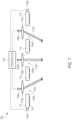
- FIG. 1shows a side view of an example of an illumination system 100, in accordance with some embodiments.
- the illumination system 100includes a light guide 114.
- the light guide 114can be formed from a substantially transparent material, such as glass or plastic.
- the light guide 114is configured to guide light from one location in the light guide 114 to another location in the light guide 114.
- the light guide 114is shaped such that light rays inside the light guide 114 are reflected at one or more surfaces of the light guide 114 via, for example, total internal reflection.
- the light guide 114has a first surface and a second surface opposite the first surface.
- the light guide 114can be shaped as a substantially planar light guide 114, with the second surface being substantially parallel to the first surface.
- the light guide 114can be shaped as a wedged light guide 114, with the second surface being angled with respect to the first surface. Other suitable shapes can also be used.
- a plurality of first individually addressable light-emitting diodes 106A, 106Bdirect first light 108A, 108B into the light guide 114 through the first surface of the light guide 114.
- the plurality of individually addressable light-emitting diodes 106A, 106Bcan be formed as one or more arrays of light-emitting diodes 106A, 106B.
- Each array of light-emitting diodes 106A, 106Bcan have electrical connections that allow each light-emitting diode in the array to be individually addressable.
- one or more of the individually addressable light-emitting diodes 106A, 106Bcan be formed discretely (e.g., not included as part of an array).
- FIG. 6discussed below, shows an example of such a discretely formed light-emitting diode.
- focusing optics 110A, 110Bat least partially focus the first light 108A, 108B to emerge from the light guide 114 through the second surface of the light guide 114 as projected light 112A, 112B.
- the focusing optics 110A, 110Bcan collimate the first light 108A, 108B, such that the projected light 112A, 112B can emerge as being collimated or substantially collimated.
- the focusing optics 110A, 110Bat least partially focus the first light 108A, 108B to form exiting light, where the exiting light is diverging and has a divergence angle that is smaller than a divergence angle of light emitted from the light-emitting diodes 106A, 106B.
- the focusing optics 110A, 110Bat least partially focus the first light 108A, 108B to form exiting light, where the exiting light is converging to a focus and then diverging thereafter, and, in divergence, has a divergence angle that is smaller than a divergence angle of light emitted from the light-emitting diodes 106A, 106B.
- the focusing optics 110A, 110Bcan be formed as refractive projection optics, which can project light from the plurality of first individually addressable light-emitting diodes into a far field in a substantially imaging fashion. For example, a position of a particular light-emitting diode can correlate with an angle in the far field at which light from the light-emitting diode emerges. In some examples, most or all of the projected light 112A, 112B (defined as projected light 112A, 112B having an intensity greater than or equal to half of a peak intensity) can fall within a range of propagation angles (being defined with respect to a surface normal of the second surface of the light guide 114).
- the range of propagation anglescan be between about 30 degrees and about 60 degrees.
- the projected lightcan fall between about negative 30 degrees and about positive 30 degrees, measured with respect to the surface normal.
- Other numerical examplesare also possible.
- Other suitable angular rangescan also be used.
- a plurality of second light-emitting diodes 118A, 118Bdirect second light into the light guide 114 as guided light 120 that is guided between the first surface of the light guide 114 and the second surface of the light guide 114.
- the second light-emitting diodecan be located along an edge of the light guide 114 and can direct the second light into the light guide 114 through the edge of the light guide 114.
- the second light-emitting diodecan be located proximate an edge of the light guide 114 and can couple second light into the light guide 114 via the first or second surfaces of the light guide 114.
- the second light-emitting diodescan be spaced apart along one or more edges of the light guide 114 and may be oriented such that their respective emissions may not be parallel to one other. In other words, an emission of one second light-emitting diode can be angled with respect to an emission of another second light-emitting diode.
- One or more second light-emitting diodescan be included in an array or can be formed discretely.
- a plurality of light-extraction features 122are disposed on the second surface of light guide 114.
- the light-extraction features 122direct at least some of the guided light 120 out of the light guide 114 through the second surface of the light guide 114 as scattered light 124.
- the light-extraction features 122can be distributed over a relatively large area of the second surface of the light guide 114.
- the light-extraction features 122can include a roughened surface, such as a diffuser, a plurality of relatively small shaped structures, such as prisms or microprisms that can be embossed or injection molded, a plurality of absorbing or scattering elements, such as dots of scattering ink that can be screen printed or inkjet printed, and/or other light-scattering elements.
- the first surface of the light guide 114can optionally include a reflector that can direct the scattered light 124 away from the first surface and toward the second surface of the light guide 114.
- the light-extraction features 122are disposed on the second surface of the light guide 114, as shown in the example of FIG. 1 .
- the light-extraction features 122can be absent in regions of the second surface of the light at which the projected light 112A, 112B can propagate.
- the light-extraction features 122can be absent in the region of the reflector.
- a controller 102can electrically control, via a first electrical connection 104A and a second electrical connection 104B, the plurality of first individually addressable light-emitting diodes, such as to determine which of the light-emitting diodes are turned on or off.
- the term "electrical connection”may be, for example, a hardwired connection or a remotely coupled connection (e.g., a wireless connection).
- the controller 102powers a first light-emitting diode of the plurality
- the projected light 112A, 112Bcan have an angular output having a first width.
- the controller 102powers the first light-emitting diode of the plurality and an adjacent second light-emitting diode of the plurality
- the projected light 112A, 112Bcan have an angular output having a second width that is, for example, twice the first width.
- Other suitable examplescan also be used. In this manner, the controller 102 can allow a user to tailor a beam shape and/or a beam direction of a light output of the illumination system 100.
- the controller 102can perform the controlling via, for example, routing to a central microcontroller, passive/active matrix addressing, and/or addressing of integrated switches over a common data line through a digital communication protocol (not shown in FIG. 1 but understandable to a person of ordinary skill in the art upon reading and understanding the disclosed subject matter).
- the controller 102can receive input from the user, such as via a user interface, to select the beam shape and/or beam direction.
- the inputcan include a selection of one of a predefined or specified plurality of configurations.
- the controller 102can receive one or more inputs to determine a desired light distribution.
- the inputscan include occupant location and activity, time of day, ambient lighting, and others. Suitable sensors may be connected to or integrated into the control system to provide input.
- the controller 102can also electrically control, via 116A and 116B, the at least one second light-emitting diode 118A, 118B.
- the controller 102can allow selection of a configuration of the projected light 112A, 112B (resulting from control of the plurality of first individually addressable light-emitting diodes 106A, 106B), but not allow selection of a configuration of the second light-emitting diode(s) 118A, 118B.
- the projected light 112A, 112Bcan be controlled, such as by a user, but the scattered light 124 may not be controllable by the user.
- the illumination system 100can allow relatively high resolution of the light output in the projected light 112A, 112B, while achieving a relatively wide angular output by addition of the scattered light 124 to the projected light 112A, 112B.
- the illumination system 100can combine projected light 112A, 112B, which can have beam propagation directions relatively close to a surface normal of the second surface of the light guide 114 (e.g. relatively small propagation angles, such as less than about 40 degrees, less than about 50 degrees, less than about 60 degrees, or others), with scattered light 124, which can include beam propagation directions relatively far from the surface normal of the second surface of the light guide 114 (e.g. relatively large propagation angles, greater than about 40 degrees, greater than about 50 degrees, greater than about 60 degrees, or others).
- the projection opticscan project a digitally addressable high-luminance LED source for beam shaping and steering at angles that can be substantially outside direct view for users.
- the scattering opticscan be designed such that light is mainly scattered towards higher angles that may be in direct view and can be distributed over a larger area to reduce luminance contrast and associated glare.
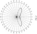
- FIG. 2shows a polar plot of an example of a distribution of the scattered light 124 of the illumination system 100 of FIG. 1 , in accordance with some embodiments.
- anglesare formed with respect to a surface normal of the second surface of the light guide 114. For example, an angle of zero degrees coincides with the surface normal, while an angle of positive 90 degrees or negative 90 degrees is essentially parallel to the second side of the light guide 114.
- the scattered light distributionis bifurcated, having a first peak separate from a second peak.
- a bifurcated light distributioncan be referred to as a batwing distribution.
- the first peaklies between negative 70 degrees and negative 60 degrees
- the second peaklies between positive 60 degrees and positive 70 degrees.
- Other numerical rangescan also be used.
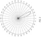
- FIG. 3shows a polar plot of an example of a distribution of the projected light 112A, 112B of the illumination system 100 of FIG. 1 , in accordance with some embodiments.
- anglesare formed with respect to the surface normal of the second surface of the light guide 114.
- the scattered light distributionis relatively sharply peaked, having a single peak.
- the single peaklies between positive 20 degrees and positive 30 degrees. Other numerical ranges can also be used.
- the single peakcan correspond to a light from a single light-emitting diode.
- the projected light distribution from each light-emitting diodecan have a width similar to the width shown in FIG. 3 , but angularly offset from the distribution shown in FIG. 3 .
- the controller 102can effectively combine the individual projected light distributions that correspond to the light-emitting diodes that are powered. For example, the controller 102 can move the relatively narrow peak to another angle by electrically powering another light-emitting diode at a different location. As another example, the controller 102 can widen the angular output by electrically powering multiple light-emitting diodes, optionally at contiguous locations.
- the focusing optics 110A, 110Binclude lenses that are formed separately from the light guide 114, such that the output of the lenses propagates through the first surface of the light guide and the second surface of the light guide without any focusing or decollimating effects being imparted by the generally planar first and second surfaces of the light guide 114.
- Other configurations for the focusing opticsare possible, including integrating the focusing optics into the first and/or second surfaces of the light guide 114.
- FIG. 4shows a side view of another example of an illumination system 400, in accordance with some embodiments.
- Elements 402-422 of FIG. 4are the same as or similar respective functions and structures of corresponding elements 102-122 of FIG. 1 .
- Focusing optics 426A, 428A, 426B, 428Bcan be formed as respectively shaped portions (e.g., curved portions) of the first and second surfaces of the light guide 414.
- focusing optics 426A and 428Acan at least partially focus the light emitted from light-emitting diode array 406A
- focusing optics 426B and 428Bcan at least partially focus the light emitted from light-emitting diode array 406B.
- Other suitable configurationsare possible.
- the focusing opticscan be integrated with the light guide 414. Any or all of the shaped portions can be used instead of or in addition to any of the lenses shown in FIG. 1 .
- the light-emitting diodes that generate the scattered lightare located along one or more edges of the light guide.
- Other configurationsare possible for these light-emitting diodes that generate the scattered light, including locating them alongside the light-emitting diodes that generate the projected light.
- FIG. 5shows a side view of another example of an illumination system 500, in accordance with some embodiments.
- Elements 502-528 of FIG. 5are the same as or similar respective functions and structures of corresponding elements 402-428 of FIG. 4 .
- the array 506A of light-emitting diodescan include one or more light-emitting diodes 530 at its periphery, which can generate light that is directed to the light-extraction features 522 to form the scattered light 524.
- Other arrays of light-emitting diodes, such as 506B,can include similar light-emitting diodes 530 at their respective peripheries, which can similarly generate the light that forms the scattered light 524.
- Light from the interior light-emitting diodes of the arraycan form the projected light.
- a reflector 532can split off light from the light-emitting diode 530 and direct the light into the light guide 514 as guided light.
- the light-extraction features 522can direct at least some of the guided light out of the light guide 514 through the second surface of the light guide 514 as scattered light 524.
- the reflector 532can be formed as a discontinuity between adjacent portions of the light guide 514.
- the reflector 532can reflect via, for example, total internal reflection or can include one or more reflective and/or dielectric layers that can reflect the light into the light guide 514.
- the reflector 532can extend around a perimeter of the array 506A of light-emitting diodes, so as to direct light from multiple peripherally located light-emitting diodes from the array 506A into the light guide 514 as guided light and out of the light guide 514 as scattered light.
- the light-emitting diodesare arranged in one or more arrays.
- Other configurationsare possible for the light-emitting diodes, including using discretely formed light-emitting diodes.
- FIG. 6shows a side view of another example of an illumination system 600, in accordance with some embodiments.
- the configuration of FIG. 6uses discretely formed light-emitting diodes, rather than arrays of light-emitting diodes.
- a controller 602can control a light-emitting diode 606A, which can emit light into focusing optics 610A to produce projected light 612A.
- the controller 602can further control a light-emitting diode 606B, which can emit light into focusing optics 610B to produce projected light 612B.
- the controller 602can further control a light-emitting diode 606C, which can emit light into focusing optics 610C to produce projected light 612C.
- the projected lights 612A, 612B, and 612Ccan optionally be angled with respect to one another.
- Each of the focusing optics 610A, 610B, 610Ccan be formed as an individual lens or can optionally be formed integrally with the light guide 614, as shown in FIGS. 4 and 5 .
- the controller 602can additionally control light-emitting diodes 618A and 618B, which can direct light into the light guide 614 to form the scattered light.
- FIG. 7shows a side view of another example of an illumination system 700, outside the scope of the claimed invention, which differs from the configurations in FIGS. 1 and 4-6 in that the projected light 712A, 712B, 712C can pass through one or more holes 734A, 734B, 734C in the light guide 714.
- the projected light 712A, 712B, 712Ccan propagate through air after exiting the focusing optics 710A, 710B, 710C, without entering the light guide 714 through the first surface, passing through an interior of the light guide 714, and exiting the light guide 714 at the second surface.
- a controller 702can control a light-emitting diode 706A, which can emit light into focusing optics 710A to produce projected light 712A.
- the controller 702can further control a light-emitting diode 706B, which can emit light into focusing optics 710B to produce projected light 712B.
- the controller 702can further control a light-emitting diode 706C, which can emit light into focusing optics 710C to produce projected light 712C.
- the projected lights 712A, 712B, and 712Ccan optionally be angled with respect to one another.
- the illumination system 700can include a light guide 714 having a first surface and a second surface opposite the first surface.
- the light guide 714can define a hole, such as 734A, 734B, 734C, that extends through the light guide 714 from the first surface to the second surface.
- a first light-emitting diodesuch as 706A, 706B, 706C, can emit first light.
- Focusing opticssuch as 710A, 710B, 710C, can at least partially focus the first light and direct the at least partially focused first light through the corresponding hole 734A, 734B, 734C in the light guide 714 to emerge from the hole 714 at the second surface of the light guide 714 as projected light.
- a second light-emitting diode, such as 718A, 718Bcan direct second light into the light guide 714 as guided light that can be guided between the first surface and the second surface.
- the focusing opticscan be located external to the light guide 714, such that the at least partially focused first light enters the corresponding hole 734A, 734B, 734C at the first surface of the light guide 714.
- the focusing opticssuch as lenses 710A, 710B, 710C, can be located at least partially within the respective hole 734A, 734B, 734C.
- the focusing opticscan be recessed within the hole by an amount that can create a cut-off for light beyond an intended projection angle that might otherwise cause glare for a viewer.
- one or more of the holes 734A, 734B, 734Ccan be substantially cylindrical.
- one or more of the holes 734A, 734B, 734Ccan extend along a hole axis, and can have a substantially circular cross-section, taken in a plane orthogonal to the hole axis.
- the hole axiscan be substantially orthogonal to the second surface of the light guide.
- two or more of the corresponding hole axescan be substantially parallel.
- two or more of the corresponding hole axescan be angled with respect to each other.
- the illumination system 700can include a plurality of light-extraction features 722 that can direct at least some of the guided light out of the light guide 714 through the second surface of the light guide 714 as scattered light.
- the illumination system 700is shown in FIG. 7 as using discretely formed light-emitting diodes, similar to those shown in FIG. 6 , the configuration can also use one or more arrays of light-emitting diodes, similar to those shown in FIGS. 1 , 4 , and 5 , or a combination of at least one discretely formed light-emitting diode and at least one array of light-emitting diodes.
- an illumination systemcan optionally mix configurations of the focusing optics and the light guide.
- an illumination systemcan include one or more focusing optics formed separate from the light guide and configured to direct light into and out of the light guide as in FIGS. 1 and 6 , one or more focusing optics formed integrally with the light guide as in FIGS. 4 and 5 .
- the scattering elementscan optionally be divided into zones. Each zone can produce a different output light distribution.
- the light-emitting diodescan be individually addressable for each zone.
- the zonescan have a same or similar polar angular distribution but different azimuthal angular distributions. In this manner, the illumination system can effectively steer the scattered light. Because the scattered light can extend over a wide angular range, this arrangement can effectively allow beam steering over the wide angular range.
- the projected light and/or the scattered lightcan be made tunable in color, by coupling at least two different primary light-emitting diodes into the respective optics that can be separately addressed.
- Color tuning in this mannercan support functionalities like dim-to-warm, white correlated color temperature tuning, or full color tuning.
- light guide plates and scattering elementscan provide good color mixing, which can help avoid or eliminate visualizing the individual color contributions from the individual light-emitting diodes.
- multiple colorsmay be implemented in a single pixilated light source, such as an array of light-emitting diodes.
- An optional mixing optic or opticssuch as a scattering layer, can mix the colors prior to the light being projected. Because the mixing optic can reduce a spatial resolution of the pixilated light source, a practical design can typically trade off between color mixing and spatial resolution.
- multiple colorsmay be implemented as separate pixilated sources, with each source having only one color. If the projection optics produce beams that traverse similar paths in the far field, such as by being parallel to one another, then colors can mix in the far field. The layout of the pixilated sources relative to each other can minimize or reduce color shadows.
- color mixing in the far fieldcan also be achieved if the collective light distribution of the projection optics for a color is the same for all the colors.
- the light-emitting diodes that form the scattered lightcan have a higher correlated color temperature (CCT) than the light-emitting diodes that form the projected light.
- CCTcorrelated color temperature
- the scattered lightcan have a correlated color temperature of about 5000K or higher, while the projected light can have a correlated color temperature between about 2700K and about 4000K.
- Distributing the correlated color temperatures in this mannercan help support a human-centric lighting design. For example, in an overhead lighting fixture, distributing the correlated color temperatures in this manner can deliver blue-rich light directly to the eye for circadian entrainment and other physiological benefits, while providing functional neutral or warm white downward directed light for illumination.
- the higher correlated color temperature light-emitting diodescan optionally be dimmed or turned off in the evening to reduce melatonin suppression while keeping the functional illumination provided by the lower correlated color temperature light-emitting diodes.
- the light-emitting diodes that form the scattered lightcan be tunable in correlated color temperature, while the light-emitting diodes that form the projected light can be fixed in correlated color temperature.
- allowing the scattered light to be tunable in correlated color temperaturecan allow for scene setting and/or physiological benefits.
- the illumination systemcan be formed as a dynamic lighting system, which can be used for indoor lighting, such as for hospitality, retail, office lighting, and other applications.
- FIG. 8shows an example of a method 800 for producing illumination, in accordance with some embodiments.
- the method 800can be executed on the illumination systems shown in FIGS. 1 and 4-7 , or on other suitable illumination systems.
- the method 800can produce first light with a plurality of first individually addressable light-emitting diodes.
- the method 800can direct the first light into a light guide through a first surface of the light guide.
- the method 800can at least partially focus the first light, with focusing optics, to emerge from the light guide through a second surface of the light guide as projected light, the second surface of the light guide being opposite the first surface of the light guide.
- the method 800can produce second light with a second light-emitting diode.
- the method 800can direct the second light into the light guide as guided light that is guided between the first surface and the second surface.
- the method 800can direct, with a plurality of light-extraction features, at least some of the guided light out of the light guide through the second surface of the light guide as scattered light. While only certain features of the system and method have been illustrated and described herein, many modifications and changes will occur to those skilled in the art. Method operations can be performed substantially simultaneously or in a different order.
Landscapes
- Physics & Mathematics (AREA)
- General Physics & Mathematics (AREA)
- Optics & Photonics (AREA)
- Planar Illumination Modules (AREA)
- Illuminated Signs And Luminous Advertising (AREA)
- Arrangement Of Elements, Cooling, Sealing, Or The Like Of Lighting Devices (AREA)
- Non-Portable Lighting Devices Or Systems Thereof (AREA)
- Circuit Arrangement For Electric Light Sources In General (AREA)
Description
- The present disclosure relates generally to an illumination system that can produce a dynamically variable illumination pattern.
- It is challenging for an illumination system such as that proposed in
US2020116917A1 to produce a dynamically variable illumination pattern. For example, it can be difficult to achieve both a wide beam angle and a suitable resolution over the wide beam angle. FIG. 1 shows a side view of an example of an illumination system, in accordance with some embodiments.FIG. 2 shows a polar plot of an example of a distribution of the scattered light of the illumination system ofFIG. 1 , in accordance with some embodiments.FIG. 3 shows a polar plot of an example of a distribution of the projected light of the illumination system ofFIG. 1 , in accordance with some embodiments.FIG. 4 shows a side view of another example of an illumination system, in accordance with some embodiments.FIG. 5 shows a side view of another example of an illumination system, in accordance with some embodiments.FIG. 6 shows a side view of another example of an illumination system, in accordance with some embodiments.FIG. 7 shows a side view of another example of an illumination system, in accordance with some embodiments.FIG. 8 shows an example of a method for producing illumination, in accordance with some embodiments.- Corresponding reference characters indicate corresponding parts throughout the several views. Elements in the drawings are not necessarily drawn to scale. The configurations shown in the drawings are merely examples and should not be construed as limiting in any manner.
- The embodiment depicted in
FIG 7 is not encompassed by the wording of the claims but is considered as useful for understanding the invention, which is defined by the appended claims. FIG. 1 shows a side view of an example of anillumination system 100, in accordance with some embodiments.- The
illumination system 100 includes alight guide 114. Thelight guide 114 can be formed from a substantially transparent material, such as glass or plastic. Thelight guide 114 is configured to guide light from one location in thelight guide 114 to another location in thelight guide 114. Thelight guide 114 is shaped such that light rays inside thelight guide 114 are reflected at one or more surfaces of thelight guide 114 via, for example, total internal reflection. - The
light guide 114 has a first surface and a second surface opposite the first surface. Thelight guide 114 can be shaped as a substantiallyplanar light guide 114, with the second surface being substantially parallel to the first surface. Thelight guide 114 can be shaped as awedged light guide 114, with the second surface being angled with respect to the first surface. Other suitable shapes can also be used. - A plurality of first individually addressable light-
emitting diodes first light light guide 114 through the first surface of thelight guide 114. The plurality of individually addressable light-emitting diodes diodes emitting diodes emitting diodes FIG. 6 , discussed below, shows an example of such a discretely formed light-emitting diode. - Returning to
FIG. 1 , focusingoptics first light light guide 114 through the second surface of thelight guide 114 as projectedlight FIG. 1 , the focusingoptics first light light optics first light diodes optics first light diodes - The focusing
optics light light - A plurality of second light-
emitting diodes light guide 114 as guidedlight 120 that is guided between the first surface of thelight guide 114 and the second surface of thelight guide 114. For example, the second light-emitting diode can be located along an edge of thelight guide 114 and can direct the second light into thelight guide 114 through the edge of thelight guide 114. Alternatively, the second light-emitting diode can be located proximate an edge of thelight guide 114 and can couple second light into thelight guide 114 via the first or second surfaces of thelight guide 114. The second light-emitting diodes can be spaced apart along one or more edges of thelight guide 114 and may be oriented such that their respective emissions may not be parallel to one other. In other words, an emission of one second light-emitting diode can be angled with respect to an emission of another second light-emitting diode. One or more second light-emitting diodes can be included in an array or can be formed discretely. - A plurality of light-
extraction features 122 are disposed on the second surface oflight guide 114. The light-extraction features 122 direct at least some of the guidedlight 120 out of thelight guide 114 through the second surface of thelight guide 114 as scatteredlight 124. The light-extraction features 122 can be distributed over a relatively large area of the second surface of thelight guide 114. - Such a distribution over a relatively large area can produce a relatively low, relatively uniform luminance to the
scattered light 124. This relatively low, relatively uniform luminance can reduce glare, when, for example, a user directly views the output of theillumination system 100. The light-extraction features 122 can include a roughened surface, such as a diffuser, a plurality of relatively small shaped structures, such as prisms or microprisms that can be embossed or injection molded, a plurality of absorbing or scattering elements, such as dots of scattering ink that can be screen printed or inkjet printed, and/or other light-scattering elements. The first surface of thelight guide 114 can optionally include a reflector that can direct thescattered light 124 away from the first surface and toward the second surface of thelight guide 114. The light-extraction features 122 are disposed on the second surface of thelight guide 114, as shown in the example ofFIG. 1 . The light-extraction features 122 can be absent in regions of the second surface of the light at which the projectedlight extraction features 122 can be absent in the region of the reflector. Acontroller 102 can electrically control, via a firstelectrical connection 104A and a secondelectrical connection 104B, the plurality of first individually addressable light-emitting diodes, such as to determine which of the light-emitting diodes are turned on or off. As used herein, the term "electrical connection" may be, for example, a hardwired connection or a remotely coupled connection (e.g., a wireless connection). By changing which of the first individually addressable light-emitting diodes controller 102 can change an angular output of the projectedlight controller 102 powers a first light-emitting diode of the plurality, the projectedlight controller 102 powers the first light-emitting diode of the plurality and an adjacent second light-emitting diode of the plurality, the projectedlight controller 102 can allow a user to tailor a beam shape and/or a beam direction of a light output of theillumination system 100. - The
controller 102 can perform the controlling via, for example, routing to a central microcontroller, passive/active matrix addressing, and/or addressing of integrated switches over a common data line through a digital communication protocol (not shown inFIG. 1 but understandable to a person of ordinary skill in the art upon reading and understanding the disclosed subject matter). In some examples, thecontroller 102 can receive input from the user, such as via a user interface, to select the beam shape and/or beam direction. In some examples, the input can include a selection of one of a predefined or specified plurality of configurations. In some examples, thecontroller 102 can receive one or more inputs to determine a desired light distribution. The inputs can include occupant location and activity, time of day, ambient lighting, and others. Suitable sensors may be connected to or integrated into the control system to provide input. - The
controller 102 can also electrically control, via 116A and 116B, the at least one second light-emittingdiode controller 102 can allow selection of a configuration of the projected light 112A, 112B (resulting from control of the plurality of first individually addressable light-emittingdiodes scattered light 124 may not be controllable by the user. By allowing control of the light output in this manner, theillumination system 100 can allow relatively high resolution of the light output in the projected light 112A, 112B, while achieving a relatively wide angular output by addition of thescattered light 124 to the projected light 112A, 112B. - As a result of the aforementioned embodiments, the
illumination system 100 can combine projected light 112A, 112B, which can have beam propagation directions relatively close to a surface normal of the second surface of the light guide 114 (e.g. relatively small propagation angles, such as less than about 40 degrees, less than about 50 degrees, less than about 60 degrees, or others), withscattered light 124, which can include beam propagation directions relatively far from the surface normal of the second surface of the light guide 114 (e.g. relatively large propagation angles, greater than about 40 degrees, greater than about 50 degrees, greater than about 60 degrees, or others). The projection optics can project a digitally addressable high-luminance LED source for beam shaping and steering at angles that can be substantially outside direct view for users. The scattering optics can be designed such that light is mainly scattered towards higher angles that may be in direct view and can be distributed over a larger area to reduce luminance contrast and associated glare. FIG. 2 shows a polar plot of an example of a distribution of thescattered light 124 of theillumination system 100 ofFIG. 1 , in accordance with some embodiments. In the polar plot ofFIG. 2 , angles are formed with respect to a surface normal of the second surface of thelight guide 114. For example, an angle of zero degrees coincides with the surface normal, while an angle of positive 90 degrees or negative 90 degrees is essentially parallel to the second side of thelight guide 114.- In the example of
FIG. 2 , the scattered light distribution is bifurcated, having a first peak separate from a second peak. Such a bifurcated light distribution can be referred to as a batwing distribution. In the example ofFIG. 2 , the first peak lies between negative 70 degrees and negative 60 degrees, and the second peak lies between positive 60 degrees and positive 70 degrees. Other numerical ranges can also be used. FIG. 3 shows a polar plot of an example of a distribution of the projected light 112A, 112B of theillumination system 100 ofFIG. 1 , in accordance with some embodiments. In the polar plot ofFIG. 3 , angles are formed with respect to the surface normal of the second surface of thelight guide 114.- In the example of
FIG. 3 , the scattered light distribution is relatively sharply peaked, having a single peak. In the example ofFIG. 3 , the single peak lies between positive 20 degrees and positive 30 degrees. Other numerical ranges can also be used. - The single peak can correspond to a light from a single light-emitting diode. The projected light distribution from each light-emitting diode can have a width similar to the width shown in
FIG. 3 , but angularly offset from the distribution shown inFIG. 3 . By controlling which light-emitting diodes are powered concurrently, thecontroller 102 can effectively combine the individual projected light distributions that correspond to the light-emitting diodes that are powered. For example, thecontroller 102 can move the relatively narrow peak to another angle by electrically powering another light-emitting diode at a different location. As another example, thecontroller 102 can widen the angular output by electrically powering multiple light-emitting diodes, optionally at contiguous locations. In the configuration ofFIG. 1 , the focusingoptics light guide 114, such that the output of the lenses propagates through the first surface of the light guide and the second surface of the light guide without any focusing or decollimating effects being imparted by the generally planar first and second surfaces of thelight guide 114. Other configurations for the focusing optics are possible, including integrating the focusing optics into the first and/or second surfaces of thelight guide 114. FIG. 4 shows a side view of another example of anillumination system 400, in accordance with some embodiments. Elements 402-422 ofFIG. 4 are the same as or similar respective functions and structures of corresponding elements 102-122 ofFIG. 1 .- Focusing
optics light guide 414. For example, focusingoptics diode array 406A, and focusingoptics diode array 406B. Other suitable configurations are possible. In this manner, the focusing optics can be integrated with thelight guide 414. Any or all of the shaped portions can be used instead of or in addition to any of the lenses shown inFIG. 1 . - In the configuration of
FIG. 4 , the light-emitting diodes that generate the scattered light are located along one or more edges of the light guide. Other configurations are possible for these light-emitting diodes that generate the scattered light, including locating them alongside the light-emitting diodes that generate the projected light. FIG. 5 shows a side view of another example of anillumination system 500, in accordance with some embodiments. Elements 502-528 ofFIG. 5 are the same as or similar respective functions and structures of corresponding elements 402-428 ofFIG. 4 .- The
array 506A of light-emitting diodes can include one or more light-emittingdiodes 530 at its periphery, which can generate light that is directed to the light-extraction features 522 to form thescattered light 524. Other arrays of light-emitting diodes, such as 506B, can include similar light-emittingdiodes 530 at their respective peripheries, which can similarly generate the light that forms thescattered light 524. Light from the interior light-emitting diodes of the array can form the projected light. Areflector 532 can split off light from the light-emittingdiode 530 and direct the light into thelight guide 514 as guided light. The light-extraction features 522 can direct at least some of the guided light out of thelight guide 514 through the second surface of thelight guide 514 asscattered light 524. Thereflector 532 can be formed as a discontinuity between adjacent portions of thelight guide 514. Thereflector 532 can reflect via, for example, total internal reflection or can include one or more reflective and/or dielectric layers that can reflect the light into thelight guide 514. - In some examples, the
reflector 532 can extend around a perimeter of thearray 506A of light-emitting diodes, so as to direct light from multiple peripherally located light-emitting diodes from thearray 506A into thelight guide 514 as guided light and out of thelight guide 514 as scattered light. - In the configurations of
FIGS. 1 ,4 , and5 , the light-emitting diodes are arranged in one or more arrays. Other configurations are possible for the light-emitting diodes, including using discretely formed light-emitting diodes. FIG. 6 shows a side view of another example of anillumination system 600, in accordance with some embodiments. The configuration ofFIG. 6 uses discretely formed light-emitting diodes, rather than arrays of light-emitting diodes.- In the configuration of
FIG. 6 , acontroller 602 can control a light-emittingdiode 606A, which can emit light into focusingoptics 610A to produce projected light 612A. Thecontroller 602 can further control a light-emittingdiode 606B, which can emit light into focusingoptics 610B to produce projected light 612B. Thecontroller 602 can further control a light-emittingdiode 606C, which can emit light into focusing optics 610C to produce projected light 612C. The projected lights 612A, 612B, and 612C can optionally be angled with respect to one another. Each of the focusingoptics light guide 614, as shown inFIGS. 4 and5 . - The
controller 602 can additionally control light-emittingdiodes light guide 614 to form the scattered light. FIG. 7 shows a side view of another example of anillumination system 700, outside the scope of the claimed invention, which differs from the configurations inFIGS. 1 and4-6 in that the projected light 712A, 712B, 712C can pass through one ormore holes light guide 714. For example, the projected light 712A, 712B, 712C can propagate through air after exiting the focusingoptics light guide 714 through the first surface, passing through an interior of thelight guide 714, and exiting thelight guide 714 at the second surface.- In the configuration of
FIG. 7 , acontroller 702 can control a light-emittingdiode 706A, which can emit light into focusingoptics 710A to produce projected light 712A. Thecontroller 702 can further control a light-emittingdiode 706B, which can emit light into focusingoptics 710B to produce projected light 712B. Thecontroller 702 can further control a light-emitting diode 706C, which can emit light into focusing optics 710C to produce projected light 712C. The projected lights 712A, 712B, and 712C can optionally be angled with respect to one another. - The
illumination system 700 can include alight guide 714 having a first surface and a second surface opposite the first surface. Thelight guide 714 can define a hole, such as 734A, 734B, 734C, that extends through thelight guide 714 from the first surface to the second surface. A first light-emitting diode, such as 706A, 706B, 706C, can emit first light. Focusing optics, such as 710A, 710B, 710C, can at least partially focus the first light and direct the at least partially focused first light through thecorresponding hole light guide 714 to emerge from thehole 714 at the second surface of thelight guide 714 as projected light. A second light-emitting diode, such as 718A, 718B, can direct second light into thelight guide 714 as guided light that can be guided between the first surface and the second surface. - In some examples, the focusing optics, such as
lenses light guide 714, such that the at least partially focused first light enters thecorresponding hole light guide 714. In some examples, the focusing optics, such aslenses respective hole - In some examples, one or more of the
holes holes multiple holes light guide 714, two or more of the corresponding hole axes can be substantially parallel. In some examples, in which there aremultiple holes light guide 714, two or more of the corresponding hole axes can be angled with respect to each other. - In some examples, the
illumination system 700 can include a plurality of light-extraction features 722 that can direct at least some of the guided light out of thelight guide 714 through the second surface of thelight guide 714 as scattered light. - Although the
illumination system 700 is shown inFIG. 7 as using discretely formed light-emitting diodes, similar to those shown inFIG. 6 , the configuration can also use one or more arrays of light-emitting diodes, similar to those shown inFIGS. 1 ,4 , and5 , or a combination of at least one discretely formed light-emitting diode and at least one array of light-emitting diodes. - Further, an illumination system can optionally mix configurations of the focusing optics and the light guide. For example, an illumination system can include one or more focusing optics formed separate from the light guide and configured to direct light into and out of the light guide as in
FIGS. 1 and6 , one or more focusing optics formed integrally with the light guide as inFIGS. 4 and5 . - In some examples, in combination with any of the above configurations, the scattering elements can optionally be divided into zones. Each zone can produce a different output light distribution. The light-emitting diodes can be individually addressable for each zone. For example, the zones can have a same or similar polar angular distribution but different azimuthal angular distributions. In this manner, the illumination system can effectively steer the scattered light. Because the scattered light can extend over a wide angular range, this arrangement can effectively allow beam steering over the wide angular range.
- In some examples, in combination with any of the above configurations, the projected light and/or the scattered light can be made tunable in color, by coupling at least two different primary light-emitting diodes into the respective optics that can be separately addressed. Color tuning in this manner can support functionalities like dim-to-warm, white correlated color temperature tuning, or full color tuning. In addition, light guide plates and scattering elements can provide good color mixing, which can help avoid or eliminate visualizing the individual color contributions from the individual light-emitting diodes.
- In projection optics, there are several options that can help ensure that the different primary colors have the same light distribution in the far field, so as to maintain substantial color uniformity in the far field.
- For example, multiple colors may can be implemented in a single pixilated light source, such as an array of light-emitting diodes. An optional mixing optic or optics, such as a scattering layer, can mix the colors prior to the light being projected. Because the mixing optic can reduce a spatial resolution of the pixilated light source, a practical design can typically trade off between color mixing and spatial resolution.
- As another example, multiple colors may be implemented as separate pixilated sources, with each source having only one color. If the projection optics produce beams that traverse similar paths in the far field, such as by being parallel to one another, then colors can mix in the far field. The layout of the pixilated sources relative to each other can minimize or reduce color shadows.
- As still another example, for configurations in which the light-emitting diodes are in a sparse array or are discrete, color mixing in the far field can also be achieved if the collective light distribution of the projection optics for a color is the same for all the colors.
- In some examples, the light-emitting diodes that form the scattered light can have a higher correlated color temperature (CCT) than the light-emitting diodes that form the projected light. For example, the scattered light can have a correlated color temperature of about 5000K or higher, while the projected light can have a correlated color temperature between about 2700K and about 4000K. Distributing the correlated color temperatures in this manner can help support a human-centric lighting design. For example, in an overhead lighting fixture, distributing the correlated color temperatures in this manner can deliver blue-rich light directly to the eye for circadian entrainment and other physiological benefits, while providing functional neutral or warm white downward directed light for illumination. The higher correlated color temperature light-emitting diodes can optionally be dimmed or turned off in the evening to reduce melatonin suppression while keeping the functional illumination provided by the lower correlated color temperature light-emitting diodes.
- In some examples, the light-emitting diodes that form the scattered light can be tunable in correlated color temperature, while the light-emitting diodes that form the projected light can be fixed in correlated color temperature. In addition to helping support the human-centric lighting design discussed above, allowing the scattered light to be tunable in correlated color temperature can allow for scene setting and/or physiological benefits.
- The illumination system can be formed as a dynamic lighting system, which can be used for indoor lighting, such as for hospitality, retail, office lighting, and other applications.
FIG. 8 shows an example of amethod 800 for producing illumination, in accordance with some embodiments. Themethod 800 can be executed on the illumination systems shown inFIGS. 1 and4-7 , or on other suitable illumination systems.- At
operation 802, themethod 800 can produce first light with a plurality of first individually addressable light-emitting diodes. - At
operation 804, themethod 800 can direct the first light into a light guide through a first surface of the light guide. - At
operation 806, themethod 800 can at least partially focus the first light, with focusing optics, to emerge from the light guide through a second surface of the light guide as projected light, the second surface of the light guide being opposite the first surface of the light guide. - At
operation 808, themethod 800 can produce second light with a second light-emitting diode. - At
operation 810, themethod 800 can direct the second light into the light guide as guided light that is guided between the first surface and the second surface. - At
optional operation 812, themethod 800 can direct, with a plurality of light-extraction features, at least some of the guided light out of the light guide through the second surface of the light guide as scattered light. While only certain features of the system and method have been illustrated and described herein, many modifications and changes will occur to those skilled in the art. Method operations can be performed substantially simultaneously or in a different order.
Claims (15)
- An illumination system (100, 400, 500, 600), comprising:a light guide (114, 414,514, 614) having a first surface and a second surface opposite the first surface;a plurality of first individually addressable light-emitting diodes (106A, 106B, 406A, 406B, 506A, 506B, 606A, 606B, 606C) configured to direct first light into the light guide through the first surface of the light guide;focusing optics (110A, 110B; 426A, 428A, 426B, 428B; 526A, 528A, 526B, 528B; 610A, 610B, 610C) configured to at least partially focus the first light to emerge from the light guide through the second surface of the light guide as projected light (112A, 112B; 612A, 612B, 612C);a plurality of second light-emitting diodes (118A, 118B; 418A, 418B;530; 618A, 618B) configured to direct second light into the light guide as guided light that is guided between the first surface and the second surface; anda plurality of light-extraction features (122) disposed on the second surface of the light guide and configured to direct at least some of the guided light out of the light guide through the second surface of the light guide as scattered light (124, 524), andcharacterized in that the first light does not interact with the plurality of light-extraction features
- The illumination system of claim 1, wherein the focusing optics is located external to the light guide or at the first surface of the light guide.
- The illumination system of claim 1, wherein the light guide (514) comprises a reflector (532) formed as a discontinuity between adjacent portions of the light guide (514).
- The illumination system of claim 3, wherein the reflector (532) comprises one or more reflective and/or dielectric layers that can reflect the light into the light guide (514).
- The illumination system of claim 1, wherein the focusing optics (110A, 110B) collimate the first light (108A, 108B).
- The illumination system of claim 1, further comprising a controller (102, 402, 502, 602) configured to:electrically control the plurality of first individually addressable light-emitting diodes (106A, 106B, 406A, 406B, 506A, 506B 606A, 606B, 606C);electrically power one of a plurality of specified subsets of light-emitting diodes of the plurality of first individually addressable light-emitting diodes, andreceive input that specifies which of the plurality of specified subsets is to be electrically powered.
- The illumination system of claim 1, wherein:the plurality of first individually addressable light-emitting diodes (106A, 106B; 606A, 606B, 606C) includes a first light-emitting diode; andthe focusing optics includes a first lens positioned in a first optical path between the first light-emitting diode and the first surface of the light guide.
- The illumination system of claim 7, wherein:the plurality of first individually addressable light-emitting diodes further includes a second light-emitting diode positioned away from the first light-emitting diode, the first light-emitting diode and the second light-emitting diode being located on separate substrates; andthe focusing optics includes a second lens positioned in a second optical path between the second light-emitting diode and the first surface of the light guide, the second optical path being non-overlapping with the first optical path.
- The illumination system of claim 1, wherein:the plurality of first individually addressable light-emitting diodes includes a first light-emitting diode; andthe focusing optics includes a first curved portion (426A, 426B; 526A, 526B) disposed on the first surface of the light guide and a second curved portion (428A, 428B; 528A, 528B) disposed on the second surface of the light guide, the first and second curved portions (426A, 426B, 428A, 428B; 526A, 526B, 528A, 528B) configured to at least partially focus light emitted from the first light-emitting diodes (406A, 406B, 506A, 506B).
- The illumination system of claim 9, wherein:the plurality of first individually addressable light-emitting diodes further includes a second light-emitting diode positioned away from the first light-emitting diode; andthe focusing optics includes a third curved portion disposed on the first surface of the light guide and a fourth curved portion disposed on the second surface of the light guide, the third and fourth curved portions configured to at least partially focus light emitted from the second light-emitting diode.
- The illumination system of claim 1, wherein the second light-emitting diode (118A, 118B; 418A, 418B;530; 618A, 618B) is spaced apart from the plurality of first individually addressable light-emitting diodes and configured to direct the second light into an edge of the light guide, the edge extending between the first and second surfaces of the light guide.
- The illumination system of claim 1, wherein the plurality of first individually addressable light-emitting diodes includes at least two light-emitting diodes that emit light having different correlated color temperatures.
- The illumination system of claim 1, further comprising a third light-emitting diode configured to direct third light into the light guide as guided light that is guided between the first surface and the second surface, the second light and the third light having different correlated color temperatures.
- A method for providing illumination, the method comprising:producing first light with a plurality of first individually addressable light-emitting diodes (106A, 106B, 406A, 406B, 506A, 506B, 606A, 606B, 606C);directing the first light into a light guide (114, 414,514, 614) through a first surface of the light guide;at least partially focusing the first light, with focusing optics (110A, 110B; 426A, 428A, 426B, 428B; 526A, 528A, 526B, 528B; 610A, 610B, 610C), to emerge from the light guide through a second surface of the light guide as projected light (112A, 112B; 612A, 612B, 612C), the second surface of the light guide being opposite the first surface of the light guide;producing second light with a plurality of second light-emitting diodes (118A, 118B; 418A, 418B;530; 618A, 618B);directing the second light into the light guide as guided light that is guided between the first surface and the second surface; anddirecting, with a plurality of light-extraction features (122), at least some of the guided light out of the light guide through the second surface of the light guide as scattered light (124, 524),characterized in that the first light does not interact with the plurality of light-extraction features.
- The method of claim 14, further comprising:receiving input that specifies a first subset of a plurality of specified subsets of plurality of first individually addressable light-emitting diodes; andelectrically powering the first subset of the plurality of first individually addressable light-emitting diodes.
Applications Claiming Priority (4)
| Application Number | Priority Date | Filing Date | Title |
|---|---|---|---|
| US202063047631P | 2020-07-02 | 2020-07-02 | |
| EP20190285.5AEP3954939A1 (en) | 2020-08-10 | 2020-08-10 | Integrated optical system for dynamic diffuse and directional lighting |
| US17/020,390US11262048B2 (en) | 2020-07-02 | 2020-09-14 | Integrated optical system for dynamic diffuse and directional lighting |
| PCT/US2021/039796WO2022006218A1 (en) | 2020-07-02 | 2021-06-30 | Illumination system and illumination method |
Publications (2)
| Publication Number | Publication Date |
|---|---|
| EP4176204A1 EP4176204A1 (en) | 2023-05-10 |
| EP4176204B1true EP4176204B1 (en) | 2024-01-31 |
Family
ID=79315486
Family Applications (1)
| Application Number | Title | Priority Date | Filing Date |
|---|---|---|---|
| EP21742660.0AActiveEP4176204B1 (en) | 2020-07-02 | 2021-06-30 | Illumination system and illumination method |
Country Status (5)
| Country | Link |
|---|---|
| EP (1) | EP4176204B1 (en) |
| JP (1) | JP7418650B2 (en) |
| KR (1) | KR102587669B1 (en) |
| CN (1) | CN116157622A (en) |
| WO (1) | WO2022006218A1 (en) |
Families Citing this family (1)
| Publication number | Priority date | Publication date | Assignee | Title |
|---|---|---|---|---|
| US11262048B2 (en) | 2020-07-02 | 2022-03-01 | Lumileds Llc | Integrated optical system for dynamic diffuse and directional lighting |
Family Cites Families (15)
| Publication number | Priority date | Publication date | Assignee | Title |
|---|---|---|---|---|
| US6102559A (en)* | 1999-01-25 | 2000-08-15 | Ford Motor Company | Multi-function vehicle taillight system with unitary optic |
| JP4780081B2 (en)* | 2007-02-19 | 2011-09-28 | 三菱電機株式会社 | Backlight device and transmissive display device |
| JP5580193B2 (en)* | 2007-06-14 | 2014-08-27 | コーニンクレッカ フィリップス エヌ ヴェ | LED-based lighting fixture with adjustable beam shape |
| US7872705B2 (en)* | 2007-07-29 | 2011-01-18 | Cree, Inc. | LED backlight system for LCD displays |
| EP2157366A1 (en)* | 2008-08-21 | 2010-02-24 | Koninklijke Philips Electronics N.V. | Light guide assembly |
| CN102160461A (en)* | 2008-09-17 | 2011-08-17 | 皇家飞利浦电子股份有限公司 | Lighting devices and method of lighting a room |
| KR20120066658A (en)* | 2009-09-15 | 2012-06-22 | 코닌클리즈케 필립스 일렉트로닉스 엔.브이. | Light-emitting device |
| JP6083931B2 (en) | 2011-05-27 | 2017-02-22 | エルジー イノテック カンパニー リミテッド | Lighting module |
| TW201305487A (en)* | 2011-07-13 | 2013-02-01 | Rambus Inc | Lighting assembly with controlled configurable light redirection |
| JP2013062074A (en) | 2011-09-12 | 2013-04-04 | Stanley Electric Co Ltd | Combination lamp of vehicular lamp fitting |
| US9625637B2 (en)* | 2012-08-13 | 2017-04-18 | 3M Innovative Properties Company | Diffractive lighting devices with 3-dimensional appearance |
| CN104238186A (en)* | 2013-06-20 | 2014-12-24 | 扬升照明股份有限公司 | Backlight module |
| CN105487292A (en)* | 2016-01-15 | 2016-04-13 | 京东方科技集团股份有限公司 | Backlight module, display device and driving method thereof |
| EP3572719A1 (en) | 2018-05-25 | 2019-11-27 | ZKW Group GmbH | Light module for a motor vehicle headlamp |
| KR20200042580A (en)* | 2018-10-15 | 2020-04-24 | 삼성디스플레이 주식회사 | Display device |
- 2021
- 2021-06-30EPEP21742660.0Apatent/EP4176204B1/enactiveActive
- 2021-06-30WOPCT/US2021/039796patent/WO2022006218A1/ennot_activeCeased
- 2021-06-30JPJP2023500019Apatent/JP7418650B2/enactiveActive
- 2021-06-30CNCN202180053976.3Apatent/CN116157622A/enactivePending
- 2021-06-30KRKR1020237003943Apatent/KR102587669B1/enactiveActive
Also Published As
| Publication number | Publication date |
|---|---|
| KR102587669B1 (en) | 2023-10-12 |
| JP7418650B2 (en) | 2024-01-19 |
| CN116157622A (en) | 2023-05-23 |
| WO2022006218A1 (en) | 2022-01-06 |
| JP2023525404A (en) | 2023-06-15 |
| KR20230039674A (en) | 2023-03-21 |
| EP4176204A1 (en) | 2023-05-10 |
Similar Documents
| Publication | Publication Date | Title |
|---|---|---|
| US20230304647A1 (en) | Adjustable-beam luminaires | |
| US10563844B2 (en) | Configurable luminaire with light sources variably oriented with respect to an array of concave mirrors | |
| US10378724B2 (en) | Reduced glare LED light device | |
| EP2721341B1 (en) | Solid state light fixture with a tunable angular distribution | |
| EP2167866B1 (en) | Led-based luminaire with adjustable beam shape | |
| US11346527B2 (en) | Lens for improved color mixing and beam control of an LED light source | |
| US11131432B2 (en) | Variable beam source with mixing chamber | |
| EP4176204B1 (en) | Illumination system and illumination method | |
| US11946621B2 (en) | Integrated optical system for dynamic diffuse and directional lighting | |
| EP3954939A1 (en) | Integrated optical system for dynamic diffuse and directional lighting | |
| EP3735552B1 (en) | Table lamp | |
| CA3061625C (en) | Total internal reflection lens to lessen glare and maintain color mixing and beam control | |
| US10551036B2 (en) | Light unit | |
| EP3830476B1 (en) | Collimating lens and lighting device | |
| TW202242307A (en) | Light emitting device |
Legal Events
| Date | Code | Title | Description |
|---|---|---|---|
| STAA | Information on the status of an ep patent application or granted ep patent | Free format text:STATUS: UNKNOWN | |
| STAA | Information on the status of an ep patent application or granted ep patent | Free format text:STATUS: THE INTERNATIONAL PUBLICATION HAS BEEN MADE | |
| PUAI | Public reference made under article 153(3) epc to a published international application that has entered the european phase | Free format text:ORIGINAL CODE: 0009012 | |
| STAA | Information on the status of an ep patent application or granted ep patent | Free format text:STATUS: REQUEST FOR EXAMINATION WAS MADE | |
| 17P | Request for examination filed | Effective date:20230202 | |
| AK | Designated contracting states | Kind code of ref document:A1 Designated state(s):AL AT BE BG CH CY CZ DE DK EE ES FI FR GB GR HR HU IE IS IT LI LT LU LV MC MK MT NL NO PL PT RO RS SE SI SK SM TR | |
| P01 | Opt-out of the competence of the unified patent court (upc) registered | Effective date:20230530 | |
| DAV | Request for validation of the european patent (deleted) | ||
| DAX | Request for extension of the european patent (deleted) | ||
| RIC1 | Information provided on ipc code assigned before grant | Ipc:G02B 27/09 20060101ALI20231007BHEP Ipc:F21V 8/00 20060101AFI20231007BHEP | |
| GRAP | Despatch of communication of intention to grant a patent | Free format text:ORIGINAL CODE: EPIDOSNIGR1 | |
| STAA | Information on the status of an ep patent application or granted ep patent | Free format text:STATUS: GRANT OF PATENT IS INTENDED | |
| GRAS | Grant fee paid | Free format text:ORIGINAL CODE: EPIDOSNIGR3 | |
| INTG | Intention to grant announced | Effective date:20231120 | |
| GRAA | (expected) grant | Free format text:ORIGINAL CODE: 0009210 | |
| STAA | Information on the status of an ep patent application or granted ep patent | Free format text:STATUS: THE PATENT HAS BEEN GRANTED | |
| AK | Designated contracting states | Kind code of ref document:B1 Designated state(s):AL AT BE BG CH CY CZ DE DK EE ES FI FR GB GR HR HU IE IS IT LI LT LU LV MC MK MT NL NO PL PT RO RS SE SI SK SM TR | |
| REG | Reference to a national code | Ref country code:GB Ref legal event code:FG4D Ref country code:CH Ref legal event code:EP | |
| REG | Reference to a national code | Ref country code:IE Ref legal event code:FG4D | |
| REG | Reference to a national code | Ref country code:DE Ref legal event code:R096 Ref document number:602021009066 Country of ref document:DE | |
| REG | Reference to a national code | Ref country code:LT Ref legal event code:MG9D | |
| REG | Reference to a national code | Ref country code:NL Ref legal event code:MP Effective date:20240131 | |
| PG25 | Lapsed in a contracting state [announced via postgrant information from national office to epo] | Ref country code:IS Free format text:LAPSE BECAUSE OF FAILURE TO SUBMIT A TRANSLATION OF THE DESCRIPTION OR TO PAY THE FEE WITHIN THE PRESCRIBED TIME-LIMIT Effective date:20240531 | |
| PG25 | Lapsed in a contracting state [announced via postgrant information from national office to epo] | Ref country code:LT Free format text:LAPSE BECAUSE OF FAILURE TO SUBMIT A TRANSLATION OF THE DESCRIPTION OR TO PAY THE FEE WITHIN THE PRESCRIBED TIME-LIMIT Effective date:20240131 | |
| PG25 | Lapsed in a contracting state [announced via postgrant information from national office to epo] | Ref country code:GR Free format text:LAPSE BECAUSE OF FAILURE TO SUBMIT A TRANSLATION OF THE DESCRIPTION OR TO PAY THE FEE WITHIN THE PRESCRIBED TIME-LIMIT Effective date:20240501 | |
| REG | Reference to a national code | Ref country code:AT Ref legal event code:MK05 Ref document number:1654111 Country of ref document:AT Kind code of ref document:T Effective date:20240131 | |
| PG25 | Lapsed in a contracting state [announced via postgrant information from national office to epo] | Ref country code:HR Free format text:LAPSE BECAUSE OF FAILURE TO SUBMIT A TRANSLATION OF THE DESCRIPTION OR TO PAY THE FEE WITHIN THE PRESCRIBED TIME-LIMIT Effective date:20240131 Ref country code:NL Free format text:LAPSE BECAUSE OF FAILURE TO SUBMIT A TRANSLATION OF THE DESCRIPTION OR TO PAY THE FEE WITHIN THE PRESCRIBED TIME-LIMIT Effective date:20240131 Ref country code:RS Free format text:LAPSE BECAUSE OF FAILURE TO SUBMIT A TRANSLATION OF THE DESCRIPTION OR TO PAY THE FEE WITHIN THE PRESCRIBED TIME-LIMIT Effective date:20240430 | |
| PG25 | Lapsed in a contracting state [announced via postgrant information from national office to epo] | Ref country code:ES Free format text:LAPSE BECAUSE OF FAILURE TO SUBMIT A TRANSLATION OF THE DESCRIPTION OR TO PAY THE FEE WITHIN THE PRESCRIBED TIME-LIMIT Effective date:20240131 | |
| PG25 | Lapsed in a contracting state [announced via postgrant information from national office to epo] | Ref country code:AT Free format text:LAPSE BECAUSE OF FAILURE TO SUBMIT A TRANSLATION OF THE DESCRIPTION OR TO PAY THE FEE WITHIN THE PRESCRIBED TIME-LIMIT Effective date:20240131 | |
| PG25 | Lapsed in a contracting state [announced via postgrant information from national office to epo] | Ref country code:RS Free format text:LAPSE BECAUSE OF FAILURE TO SUBMIT A TRANSLATION OF THE DESCRIPTION OR TO PAY THE FEE WITHIN THE PRESCRIBED TIME-LIMIT Effective date:20240430 Ref country code:NO Free format text:LAPSE BECAUSE OF FAILURE TO SUBMIT A TRANSLATION OF THE DESCRIPTION OR TO PAY THE FEE WITHIN THE PRESCRIBED TIME-LIMIT Effective date:20240430 Ref country code:NL Free format text:LAPSE BECAUSE OF FAILURE TO SUBMIT A TRANSLATION OF THE DESCRIPTION OR TO PAY THE FEE WITHIN THE PRESCRIBED TIME-LIMIT Effective date:20240131 Ref country code:LT Free format text:LAPSE BECAUSE OF FAILURE TO SUBMIT A TRANSLATION OF THE DESCRIPTION OR TO PAY THE FEE WITHIN THE PRESCRIBED TIME-LIMIT Effective date:20240131 Ref country code:IS Free format text:LAPSE BECAUSE OF FAILURE TO SUBMIT A TRANSLATION OF THE DESCRIPTION OR TO PAY THE FEE WITHIN THE PRESCRIBED TIME-LIMIT Effective date:20240531 Ref country code:HR Free format text:LAPSE BECAUSE OF FAILURE TO SUBMIT A TRANSLATION OF THE DESCRIPTION OR TO PAY THE FEE WITHIN THE PRESCRIBED TIME-LIMIT Effective date:20240131 Ref country code:GR Free format text:LAPSE BECAUSE OF FAILURE TO SUBMIT A TRANSLATION OF THE DESCRIPTION OR TO PAY THE FEE WITHIN THE PRESCRIBED TIME-LIMIT Effective date:20240501 Ref country code:FI Free format text:LAPSE BECAUSE OF FAILURE TO SUBMIT A TRANSLATION OF THE DESCRIPTION OR TO PAY THE FEE WITHIN THE PRESCRIBED TIME-LIMIT Effective date:20240131 Ref country code:ES Free format text:LAPSE BECAUSE OF FAILURE TO SUBMIT A TRANSLATION OF THE DESCRIPTION OR TO PAY THE FEE WITHIN THE PRESCRIBED TIME-LIMIT Effective date:20240131 Ref country code:BG Free format text:LAPSE BECAUSE OF FAILURE TO SUBMIT A TRANSLATION OF THE DESCRIPTION OR TO PAY THE FEE WITHIN THE PRESCRIBED TIME-LIMIT Effective date:20240131 Ref country code:AT Free format text:LAPSE BECAUSE OF FAILURE TO SUBMIT A TRANSLATION OF THE DESCRIPTION OR TO PAY THE FEE WITHIN THE PRESCRIBED TIME-LIMIT Effective date:20240131 | |
| PG25 | Lapsed in a contracting state [announced via postgrant information from national office to epo] | Ref country code:PT Free format text:LAPSE BECAUSE OF FAILURE TO SUBMIT A TRANSLATION OF THE DESCRIPTION OR TO PAY THE FEE WITHIN THE PRESCRIBED TIME-LIMIT Effective date:20240531 Ref country code:PL Free format text:LAPSE BECAUSE OF FAILURE TO SUBMIT A TRANSLATION OF THE DESCRIPTION OR TO PAY THE FEE WITHIN THE PRESCRIBED TIME-LIMIT Effective date:20240131 | |
| PG25 | Lapsed in a contracting state [announced via postgrant information from national office to epo] | Ref country code:SE Free format text:LAPSE BECAUSE OF FAILURE TO SUBMIT A TRANSLATION OF THE DESCRIPTION OR TO PAY THE FEE WITHIN THE PRESCRIBED TIME-LIMIT Effective date:20240131 Ref country code:PT Free format text:LAPSE BECAUSE OF FAILURE TO SUBMIT A TRANSLATION OF THE DESCRIPTION OR TO PAY THE FEE WITHIN THE PRESCRIBED TIME-LIMIT Effective date:20240531 Ref country code:PL Free format text:LAPSE BECAUSE OF FAILURE TO SUBMIT A TRANSLATION OF THE DESCRIPTION OR TO PAY THE FEE WITHIN THE PRESCRIBED TIME-LIMIT Effective date:20240131 Ref country code:LV Free format text:LAPSE BECAUSE OF FAILURE TO SUBMIT A TRANSLATION OF THE DESCRIPTION OR TO PAY THE FEE WITHIN THE PRESCRIBED TIME-LIMIT Effective date:20240131 | |
| PG25 | Lapsed in a contracting state [announced via postgrant information from national office to epo] | Ref country code:DK Free format text:LAPSE BECAUSE OF FAILURE TO SUBMIT A TRANSLATION OF THE DESCRIPTION OR TO PAY THE FEE WITHIN THE PRESCRIBED TIME-LIMIT Effective date:20240131 | |
| PG25 | Lapsed in a contracting state [announced via postgrant information from national office to epo] | Ref country code:SM Free format text:LAPSE BECAUSE OF FAILURE TO SUBMIT A TRANSLATION OF THE DESCRIPTION OR TO PAY THE FEE WITHIN THE PRESCRIBED TIME-LIMIT Effective date:20240131 | |
| PG25 | Lapsed in a contracting state [announced via postgrant information from national office to epo] | Ref country code:CZ Free format text:LAPSE BECAUSE OF FAILURE TO SUBMIT A TRANSLATION OF THE DESCRIPTION OR TO PAY THE FEE WITHIN THE PRESCRIBED TIME-LIMIT Effective date:20240131 Ref country code:EE Free format text:LAPSE BECAUSE OF FAILURE TO SUBMIT A TRANSLATION OF THE DESCRIPTION OR TO PAY THE FEE WITHIN THE PRESCRIBED TIME-LIMIT Effective date:20240131 | |
| PG25 | Lapsed in a contracting state [announced via postgrant information from national office to epo] | Ref country code:SK Free format text:LAPSE BECAUSE OF FAILURE TO SUBMIT A TRANSLATION OF THE DESCRIPTION OR TO PAY THE FEE WITHIN THE PRESCRIBED TIME-LIMIT Effective date:20240131 | |
| PG25 | Lapsed in a contracting state [announced via postgrant information from national office to epo] | Ref country code:SM Free format text:LAPSE BECAUSE OF FAILURE TO SUBMIT A TRANSLATION OF THE DESCRIPTION OR TO PAY THE FEE WITHIN THE PRESCRIBED TIME-LIMIT Effective date:20240131 Ref country code:SK Free format text:LAPSE BECAUSE OF FAILURE TO SUBMIT A TRANSLATION OF THE DESCRIPTION OR TO PAY THE FEE WITHIN THE PRESCRIBED TIME-LIMIT Effective date:20240131 Ref country code:RO Free format text:LAPSE BECAUSE OF FAILURE TO SUBMIT A TRANSLATION OF THE DESCRIPTION OR TO PAY THE FEE WITHIN THE PRESCRIBED TIME-LIMIT Effective date:20240131 Ref country code:EE Free format text:LAPSE BECAUSE OF FAILURE TO SUBMIT A TRANSLATION OF THE DESCRIPTION OR TO PAY THE FEE WITHIN THE PRESCRIBED TIME-LIMIT Effective date:20240131 Ref country code:DK Free format text:LAPSE BECAUSE OF FAILURE TO SUBMIT A TRANSLATION OF THE DESCRIPTION OR TO PAY THE FEE WITHIN THE PRESCRIBED TIME-LIMIT Effective date:20240131 Ref country code:CZ Free format text:LAPSE BECAUSE OF FAILURE TO SUBMIT A TRANSLATION OF THE DESCRIPTION OR TO PAY THE FEE WITHIN THE PRESCRIBED TIME-LIMIT Effective date:20240131 | |
| REG | Reference to a national code | Ref country code:DE Ref legal event code:R097 Ref document number:602021009066 Country of ref document:DE | |
| PG25 | Lapsed in a contracting state [announced via postgrant information from national office to epo] | Ref country code:IT Free format text:LAPSE BECAUSE OF FAILURE TO SUBMIT A TRANSLATION OF THE DESCRIPTION OR TO PAY THE FEE WITHIN THE PRESCRIBED TIME-LIMIT Effective date:20240131 | |
| PLBE | No opposition filed within time limit | Free format text:ORIGINAL CODE: 0009261 | |
| STAA | Information on the status of an ep patent application or granted ep patent | Free format text:STATUS: NO OPPOSITION FILED WITHIN TIME LIMIT | |
| PG25 | Lapsed in a contracting state [announced via postgrant information from national office to epo] | Ref country code:IT Free format text:LAPSE BECAUSE OF FAILURE TO SUBMIT A TRANSLATION OF THE DESCRIPTION OR TO PAY THE FEE WITHIN THE PRESCRIBED TIME-LIMIT Effective date:20240131 | |
| 26N | No opposition filed | Effective date:20241101 | |
| PG25 | Lapsed in a contracting state [announced via postgrant information from national office to epo] | Ref country code:MC Free format text:LAPSE BECAUSE OF FAILURE TO SUBMIT A TRANSLATION OF THE DESCRIPTION OR TO PAY THE FEE WITHIN THE PRESCRIBED TIME-LIMIT Effective date:20240131 | |
| REG | Reference to a national code | Ref country code:CH Ref legal event code:PL | |
| PG25 | Lapsed in a contracting state [announced via postgrant information from national office to epo] | Ref country code:LU Free format text:LAPSE BECAUSE OF NON-PAYMENT OF DUE FEES Effective date:20240630 | |
| PG25 | Lapsed in a contracting state [announced via postgrant information from national office to epo] | Ref country code:IE Free format text:LAPSE BECAUSE OF NON-PAYMENT OF DUE FEES Effective date:20240630 | |
| PG25 | Lapsed in a contracting state [announced via postgrant information from national office to epo] | Ref country code:SI Free format text:LAPSE BECAUSE OF FAILURE TO SUBMIT A TRANSLATION OF THE DESCRIPTION OR TO PAY THE FEE WITHIN THE PRESCRIBED TIME-LIMIT Effective date:20240131 Ref country code:BE Free format text:LAPSE BECAUSE OF NON-PAYMENT OF DUE FEES Effective date:20240630 Ref country code:CH Free format text:LAPSE BECAUSE OF NON-PAYMENT OF DUE FEES Effective date:20240630 | |
| REG | Reference to a national code | Ref country code:BE Ref legal event code:MM Effective date:20240630 | |
| PGFP | Annual fee paid to national office [announced via postgrant information from national office to epo] | Ref country code:DE Payment date:20250626 Year of fee payment:5 | |
| PGFP | Annual fee paid to national office [announced via postgrant information from national office to epo] | Ref country code:GB Payment date:20250617 Year of fee payment:5 | |
| PGFP | Annual fee paid to national office [announced via postgrant information from national office to epo] | Ref country code:FR Payment date:20250624 Year of fee payment:5 |