EP4167911B1 - Crimping methods - Google Patents
Crimping methodsDownload PDFInfo
- Publication number
- EP4167911B1 EP4167911B1EP21740350.0AEP21740350AEP4167911B1EP 4167911 B1EP4167911 B1EP 4167911B1EP 21740350 AEP21740350 AEP 21740350AEP 4167911 B1EP4167911 B1EP 4167911B1
- Authority
- EP
- European Patent Office
- Prior art keywords
- valve
- jaws
- distal
- proximal
- delivery device
- Prior art date
- Legal status (The legal status is an assumption and is not a legal conclusion. Google has not performed a legal analysis and makes no representation as to the accuracy of the status listed.)
- Active
Links
Images


Classifications
- A—HUMAN NECESSITIES
- A61—MEDICAL OR VETERINARY SCIENCE; HYGIENE
- A61F—FILTERS IMPLANTABLE INTO BLOOD VESSELS; PROSTHESES; DEVICES PROVIDING PATENCY TO, OR PREVENTING COLLAPSING OF, TUBULAR STRUCTURES OF THE BODY, e.g. STENTS; ORTHOPAEDIC, NURSING OR CONTRACEPTIVE DEVICES; FOMENTATION; TREATMENT OR PROTECTION OF EYES OR EARS; BANDAGES, DRESSINGS OR ABSORBENT PADS; FIRST-AID KITS
- A61F2/00—Filters implantable into blood vessels; Prostheses, i.e. artificial substitutes or replacements for parts of the body; Appliances for connecting them with the body; Devices providing patency to, or preventing collapsing of, tubular structures of the body, e.g. stents
- A61F2/95—Instruments specially adapted for placement or removal of stents or stent-grafts
- A61F2/9522—Means for mounting a stent or stent-graft onto or into a placement instrument
- A61F2/9524—Iris-type crimpers
- A—HUMAN NECESSITIES
- A61—MEDICAL OR VETERINARY SCIENCE; HYGIENE
- A61F—FILTERS IMPLANTABLE INTO BLOOD VESSELS; PROSTHESES; DEVICES PROVIDING PATENCY TO, OR PREVENTING COLLAPSING OF, TUBULAR STRUCTURES OF THE BODY, e.g. STENTS; ORTHOPAEDIC, NURSING OR CONTRACEPTIVE DEVICES; FOMENTATION; TREATMENT OR PROTECTION OF EYES OR EARS; BANDAGES, DRESSINGS OR ABSORBENT PADS; FIRST-AID KITS
- A61F2/00—Filters implantable into blood vessels; Prostheses, i.e. artificial substitutes or replacements for parts of the body; Appliances for connecting them with the body; Devices providing patency to, or preventing collapsing of, tubular structures of the body, e.g. stents
- A61F2/02—Prostheses implantable into the body
- A61F2/24—Heart valves ; Vascular valves, e.g. venous valves; Heart implants, e.g. passive devices for improving the function of the native valve or the heart muscle; Transmyocardial revascularisation [TMR] devices; Valves implantable in the body
- A61F2/2427—Devices for manipulating or deploying heart valves during implantation
- A61F2/243—Deployment by mechanical expansion
- A61F2/2433—Deployment by mechanical expansion using balloon catheter
- A—HUMAN NECESSITIES
- A61—MEDICAL OR VETERINARY SCIENCE; HYGIENE
- A61F—FILTERS IMPLANTABLE INTO BLOOD VESSELS; PROSTHESES; DEVICES PROVIDING PATENCY TO, OR PREVENTING COLLAPSING OF, TUBULAR STRUCTURES OF THE BODY, e.g. STENTS; ORTHOPAEDIC, NURSING OR CONTRACEPTIVE DEVICES; FOMENTATION; TREATMENT OR PROTECTION OF EYES OR EARS; BANDAGES, DRESSINGS OR ABSORBENT PADS; FIRST-AID KITS
- A61F2/00—Filters implantable into blood vessels; Prostheses, i.e. artificial substitutes or replacements for parts of the body; Appliances for connecting them with the body; Devices providing patency to, or preventing collapsing of, tubular structures of the body, e.g. stents
- A61F2/95—Instruments specially adapted for placement or removal of stents or stent-grafts
- A61F2/9522—Means for mounting a stent or stent-graft onto or into a placement instrument
- B—PERFORMING OPERATIONS; TRANSPORTING
- B23—MACHINE TOOLS; METAL-WORKING NOT OTHERWISE PROVIDED FOR
- B23P—METAL-WORKING NOT OTHERWISE PROVIDED FOR; COMBINED OPERATIONS; UNIVERSAL MACHINE TOOLS
- B23P11/00—Connecting or disconnecting metal parts or objects by metal-working techniques not otherwise provided for
- B23P11/005—Connecting or disconnecting metal parts or objects by metal-working techniques not otherwise provided for by expanding or crimping
- A—HUMAN NECESSITIES
- A61—MEDICAL OR VETERINARY SCIENCE; HYGIENE
- A61F—FILTERS IMPLANTABLE INTO BLOOD VESSELS; PROSTHESES; DEVICES PROVIDING PATENCY TO, OR PREVENTING COLLAPSING OF, TUBULAR STRUCTURES OF THE BODY, e.g. STENTS; ORTHOPAEDIC, NURSING OR CONTRACEPTIVE DEVICES; FOMENTATION; TREATMENT OR PROTECTION OF EYES OR EARS; BANDAGES, DRESSINGS OR ABSORBENT PADS; FIRST-AID KITS
- A61F2/00—Filters implantable into blood vessels; Prostheses, i.e. artificial substitutes or replacements for parts of the body; Appliances for connecting them with the body; Devices providing patency to, or preventing collapsing of, tubular structures of the body, e.g. stents
- A61F2/02—Prostheses implantable into the body
- A61F2/24—Heart valves ; Vascular valves, e.g. venous valves; Heart implants, e.g. passive devices for improving the function of the native valve or the heart muscle; Transmyocardial revascularisation [TMR] devices; Valves implantable in the body
- A61F2/2412—Heart valves ; Vascular valves, e.g. venous valves; Heart implants, e.g. passive devices for improving the function of the native valve or the heart muscle; Transmyocardial revascularisation [TMR] devices; Valves implantable in the body with soft flexible valve members, e.g. tissue valves shaped like natural valves
- A—HUMAN NECESSITIES
- A61—MEDICAL OR VETERINARY SCIENCE; HYGIENE
- A61F—FILTERS IMPLANTABLE INTO BLOOD VESSELS; PROSTHESES; DEVICES PROVIDING PATENCY TO, OR PREVENTING COLLAPSING OF, TUBULAR STRUCTURES OF THE BODY, e.g. STENTS; ORTHOPAEDIC, NURSING OR CONTRACEPTIVE DEVICES; FOMENTATION; TREATMENT OR PROTECTION OF EYES OR EARS; BANDAGES, DRESSINGS OR ABSORBENT PADS; FIRST-AID KITS
- A61F2240/00—Manufacturing or designing of prostheses classified in groups A61F2/00 - A61F2/26 or A61F2/82 or A61F9/00 or A61F11/00 or subgroups thereof
- A61F2240/001—Designing or manufacturing processes
- A—HUMAN NECESSITIES
- A61—MEDICAL OR VETERINARY SCIENCE; HYGIENE
- A61F—FILTERS IMPLANTABLE INTO BLOOD VESSELS; PROSTHESES; DEVICES PROVIDING PATENCY TO, OR PREVENTING COLLAPSING OF, TUBULAR STRUCTURES OF THE BODY, e.g. STENTS; ORTHOPAEDIC, NURSING OR CONTRACEPTIVE DEVICES; FOMENTATION; TREATMENT OR PROTECTION OF EYES OR EARS; BANDAGES, DRESSINGS OR ABSORBENT PADS; FIRST-AID KITS
- A61F2250/00—Special features of prostheses classified in groups A61F2/00 - A61F2/26 or A61F2/82 or A61F9/00 or A61F11/00 or subgroups thereof
- A61F2250/0014—Special features of prostheses classified in groups A61F2/00 - A61F2/26 or A61F2/82 or A61F9/00 or A61F11/00 or subgroups thereof having different values of a given property or geometrical feature, e.g. mechanical property or material property, at different locations within the same prosthesis
- A61F2250/0039—Special features of prostheses classified in groups A61F2/00 - A61F2/26 or A61F2/82 or A61F9/00 or A61F11/00 or subgroups thereof having different values of a given property or geometrical feature, e.g. mechanical property or material property, at different locations within the same prosthesis differing in diameter
Definitions
- This applicationis related to crimping devices and methods for prosthetic heart valves, stents, and the like.
- Crimping a prosthetic heart valve onto a catheter-based delivery systemis typically done using crimping devices that have a set of jaws that form a single continuous face as they close, which compresses the valve equally along its length to a smaller diameter.
- the entire valveis positioned within the jaws as jaws close, which applies crimping forces uniformly across the axial length of the valve and uniformly reduces the whole valve at the same rate to the same final crimped diameter.
- EP 2 014 257 A1describes a device for crimping an implantable device or a part thereof between a radially expanded condition and a radially contracted condition.
- the deviceincludes first and second annular bodies arranged about a common axis, and a ring-like array of linear crimping elements having respective opposite ends linked to the first and second annular bodies, respectively.
- These annular bodiesare relatively rotatable around the common axis between a first position, wherein the annular array of crimping elements defines a wider orifice for receiving a device to be crimped, and a second position, wherein the annular array of crimping elements defines a narrower orifice.
- the devicefurther includes a brake member selectively actuatable to prevent the relative angular rotation of the first and second annular bodies.
- the operatorcrimps a first of annular end portions of the implantable device. Then, with the inflow portion crimped and safely retained within the device and secured by the respective brake member, the operator crimps the opposite outflow portion, using the twin devices.
- valvesare crimped over an inflatable balloon and between proximal and distal shoulders mounted on a shaft inside the balloon.
- Crimping methods disclosed hereincan include multiple compression steps with the valve located in different axial positions relative to the crimping jaws at each different step.
- the valvemay extend partially outside of the crimping jaws during certain crimping steps, such that the crimping force is only applied to the part of the valve that is inside the jaws.
- Exemplary crimping devices disclosed hereincan include two or more sets of side-by-side jaws that close down to different inner diameters, such that different parts of a valve get compressed to different outer diameters at the same time during a single crimping step.
- Exemplary methodscan comprise any combination of the following steps: inserting a prosthetic heart valve into a crimping device in a radially expanded state such that the valve is positioned within crimping jaws of the crimping device; positioning an inflatable balloon of the delivery device within the valve; positioning the valve and the delivery device in a first axial position where the valve and at least part of the distal shoulder of the delivery device are within the jaws between the proximal and distal ends of the jaws, and where the entire proximal shoulder is outside of the jaws proximal to the proximal end of the jaws; closing and opening the jaws with the valve and delivery device in the first axial position, such that the valve is at least partially crimped onto the balloon between the proximal shoulder and the distal shoulder; repositioning the valve and delivery device from the first axial position to a second axial position where a first distal portion of the valve and at least part of the distal shoulder are within the jaws, and where a first proximal portion
- Exemplary crimping devicescan comprise: first jaws having an open position and a fully closed position, wherein the first jaws have a first inner diameter in the fully closed position, and second jaws having an open position and a fully closed position, wherein the second jaws have a second inner diameter in the fully closed position, and wherein the second inner diameter is smaller than the first inner diameter.
- the first jaws and the second jawscan be axially side-by-side, and/or in contact with each other.
- the first jawscan have a greater axial dimension than the second jaws, such as at least two time or at least five times greater.
- the first inner diameter and the second inner diametercan be selected to correspond to desired outer diameters of prosthetic heart valve that is crimped by the device.
- the first jaws and the second jawscan be actuated at the same time using a common actuator, such as a handle that the user pulls.
- the prosthetic heart valves described hereincan be adapted for delivering and implanting in any of the native annuluses of the heart (e.g., the aortic, pulmonary, mitral, and tricuspid annuluses), and can be used with any of various delivery devices for delivering the prosthetic valve using any of various delivery approaches (e.g., retrograde, antegrade, transseptal, transventricular, transatrial, etc.). Crimping devices disclosed herein can be used with any suitable types of prosthetic heart valves, including those described herein, and can be used in conjunction with any of various delivery devices for delivering the prosthetic valve using any of various delivery approaches.
- the native annuluses of the hearte.g., the aortic, pulmonary, mitral, and tricuspid annuluses
- Crimping devices disclosed hereincan be used with any suitable types of prosthetic heart valves, including those described herein, and can be used in conjunction with any of various delivery devices for delivering the prosthetic valve using any of various delivery approaches.
- valves and frames disclosed hereinare described using an axial direction defined by the centerline of the annular frame and the overall blood flow direction from an inflow end to an outflow end, a radial direction that is defined as radiating perpendicularly from the centerline of the frame, and a circumferential direction that is perpendicular to the axial and radial directions and extends around the centerline of the frame.
- the crimping device and crimping jaws disclosed hereinare described using axial and radial directions that are defined by the axial and radial dimensions of a valve that is crimped by the device.
- the term “inner”refers to objects, surfaces, and areas proximal to the centerline of the frame or device and the term “outer” refers objects, surfaces and areas that are farther from the centerline of the frame or device.
- Some crimping devices disclosed hereininclude stacked side-by-side jaw sets which are able to move independently or together as one to crimp a device to different diameters along its length.
- the use of stacked jaw sets which are capable of independent motionhas several advantages to current designs.
- Some embodimentscan allow for a continuous unified jaw face through a portion of the crimping process, which can be critical to prevent frame damage due to snags during axial expansion, while allowing a section of the jaws to compress a region to a smaller diameter at the end of the process. This allows a user to do things like tuck in apexes to prevent snagging, or create a football-like shapes to aid insertion or device loading. Some crimping devices can achieve this motion without requiring any additional action from the operator beyond the basic actions used in a normal crimper. As the handle is rotated, the crimper jaws can start their motion together and end at different stopping positions. These features can improve device performance without requiring complex multi-stage crimping procedures.
- novel methods described hereinthat can also be used to crimp a device in a more desirable manner using a conventional crimper having only one set of jaws.
- a conventional crimping methodan expanded device is placed inside the crimping aperture and the uniform jaws compress the device uniformly to a compressed state, such that all parts of the device are radially compressed at the same rate and to the same diameter, and then the jaws are released.
- the resulting shape of the crimped devicemay not be uniform, as some parts of the device may deform more than other or recoil more than others.
- the final shape of the crimped deviceis inherent based on the structure of the device (e.g., the amount of material inside a valve frame, thicknesses of the frame, outer skirts, etc.).
- this conventional approachcan result in the crimped device having undesirable shape properties, which can lead to harmful outcomes for a patient. For example, parts of the device that project too far outwards can catch on the sheath, vessels, or native valve region and can prevent the device from successfully travelling to the implant location.
- Some methods disclosed hereinclude purposeful shaping of device through multi-stage crimping processes, which can allow a person to target a more desirable crimped profile for the device for passing through the anatomy to the implant location. This changes the crimped device shape from being dependent solely on the device design and shifts it to being controlled also by an optimized preparation procedure. This can decrease the likelihood of an adverse event due to the valve catching on the sheath, vessels, or annulus, for example.
- a desirable crimped profileis one in which the leading edge of the device is most protected. Such protection can result from a combination of how large the diameter is of the distal end of the delivery system compared to how small the diameter is of the distal edge of the device crimped onto the delivery system.
- Targeted crimping in certain portions of the devicecan help achieve such a desirable crimped profile.
- targeted crimpingcan be performed by placing only certain axial sections of the valve within the crimping jaws such that one axial portion receiving compressing force while portions that are distal to the jaws and/or proximal to the jaws receive no direct crimping force from the jaws.
- FIG. 1Ashows an exemplary prosthetic heart valve 2 that can be used with the herein disclosed crimping devices and crimping methods.
- the valve 2is just one example, and many other implantable device can be used as well, including stents, valves, frames, and any other radially compressible device.
- Such devicecan include annular frames, such as the frame 4, that are radially compressible to be mounted on a delivery device and later radially expandable within a patient's body.
- Such framescan include self-expandable frames (e.g., made of superelastic materials) and balloon-expandable frames (e.g., made of cobalt chromium or stainless steel).
- the crimped devicecan also include various other components, such as a leaflet structure 6, an inner skirt 8, and/or an outer skirt 10.
- the valve 2can be configured for placement at a native aortic valve region of heart, while other subject devices can be configured for placement at other heart locations or other parts of the body.
- the outer skirt 10is positioned at a blood inflow end of the valve 2, with the opposite end being a blood outflow end of the valve.
- FIG. 1Ashows the valve 2 in a radially expanded state
- FIG. 1Bshows the valve in a radially compressed or crimped state
- the valve 2In the crimped state, the valve 2 has a smaller radial dimension (i.e., its outer diameter) and a longer axial dimension (i.e., its axial length).
- Some parts of the valve 2can have slightly different outer diameters when in the crimped state. For example, in some circumstances the axial zone including the outer skirt 10 can be slightly bulkier and have a larger outer diameter compared to other portions of the valve.
- the final crimped state of a devicecan be better customized and controlled, such that the outer diameters at different axial locations along the valve are not just a result of the structure of the device itself, but also a result of the crimping method used and/or the type of crimping device used.
- FIG. 2shows a distal end portion of an exemplary delivery device with the valve 2 crimped onto it.
- Other delivery devicescan also be used with the herein disclosed technology.
- the valveis crimped onto a shaft 11 over an inflatable balloon 12 between a distal shoulder 14 and a proximal shoulder 16.
- the shoulders 14 and 16can be positioned around the shaft 11 within the balloon 12.
- the shoulders 14, 16can provide protection to the ends of the valve 2 to help prevent the ends of the valve from snagging on a catheter wall, a vessel wall, or other structure while the valve is being delivered.
- the shoulderscan also help keep the valve from migrating axially relative to the inner shaft 11.
- the balloon 12can be inflated to radially expand the valve and implant it in the aortic valve region (or other target location).
- FIGS. 3 and 4illustrate an exemplary crimping device, or crimper, 20 that is used to crimp a prosthetic heart valve onto a delivery device.
- the crimper 20comprises an outer housing 22 and crimping jaws 24 with a central opening 26 and an actuation handle 28.
- a radially expanded valveis placed in the opening 26 with the jaws 24 open ( FIG. 3 ).
- the handle 28With a delivery device positioned within the expanded valve, the handle 28 is actuated to cause the jaws 24 to closed down ( FIG. 4 ) and crimp the valve onto the delivery device.
- the jaws 24comprise several individual pieces that all move inwardly in unison to uniformly reduce the diameter of the opening 26 and apply even crimping pressure around the valve.
- the handle 28is released, the jaws open up and the delivery device with the valve mounted thereon can be removed or repositioned for another round of crimping.
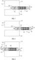
- FIGS. 5-9illustrate exemplary crimping steps.
- Various novel multi-stage crimping methodscan include any combination of the steps illustrated in FIGS. 5-9 and/or other acts.
- the steps in FIGS. 5-9can all be performed sequentially.
- the step of FIGS. 7may not be included, or the step of FIG. 8 may not be included, or the step of FIG 9 may not be included.
- additional crimping stepsare performed in addition to, or in place of, the steps shown in FIGS. 5-9 .
- the crimping jaws 40are illustrated with simple rectangles that represent a typically annular array of crimping jaws, like those shown in FIGS. 3 and 4 .
- the jaws 40include a first axial end 70 and an opposing second axial end 72.
- a valvecan be inserted into the jaws 40 from either axial end. While the jaws 40 comprise multiple individual jaw pieces that abut each other to form an annular structure, collectively the radially inner surfaces of the jaws 40 can be generalized as forming a smooth, uniform diameter, cylindrical inner surface extending between the axial ends 70 and 72.
- FIG. 5the jaws 40 are open, similar to FIG. 3 , while in FIGS. 6-9 the jaws are closed, similar to FIG. 4 .
- a radially expanded valve 42is positioned within the jaws 40 with a delivery device positioned within the valve.
- the valveis positioned such that a proximal end of the valve (right side) is about even with the first axial end 70 of the jaws, and the delivery device is positioned to match the position of the valve.
- the delivery device in this exampleincludes an inner shaft 44, an inflatable balloon 46, a proximal shoulder 48, and a distal shoulder 50.
- the valveis oriented axially between the two shoulders.
- the distal shoulder 50is at least partially positioned within the jaws 40, while the proximal shoulder 48 is positioned outside of the jaws, proximal to the first axial end 70 of the jaws.
- FIG. 6shows the configuration after the jaws 40 are closed down from the position of FIG. 5 , radially compressing the valve around the inner shaft 44 and balloon 46, between the shoulders 48 and 50.
- the whole valveis within the jaws and receives uniform crimping contact across the valve from the jaws.
- the valve frame 60e.g., a cobalt chromium alloy frame.
- FIG. 7the delivery device and valve have been shifted axially after the crimping step of FIG. 6 .
- a distal portion of the valveis still within the jaws while a proximal portion of the valve is outside the first axial end 70 of the jaws.
- the valvemay be about half in and half out of the jaws in this position, for example.
- the blood inflow end of the valve that includes the outer skirt 62is within the jaws. This is also the distal end of the valve as mounted on the delivery device.
- the distal portion of the valvereceives a second crimping from the jaws while the proximal portion of the valve does not. This can result in the distal portion of the valve having a smaller outer diameter than the proximal portion of the valve (though this difference in outer diameters is not shown in the figures).
- FIG. 8the delivery device and valve have been shifted further axially after the crimping step of FIG. 7 .
- a distal portion of the valveis still within the jaws, though the axial length of the distal portion within the jaws is shorter than in the position of FIG. 7 .
- the axial length of the proximal portion of the valve that is outside the first axial end 70 of the jawsis longer than in the position of FIG. 7 .
- the valvemay be about one forth in and three fourths out of the jaws in this position, for example.
- about half of the outer skirt 62is within the jaws, and only that portion of the valve receives a crimping from the jaws. This can result in the distal end of the valve having an even smaller outer diameter.
- the distal shouldermay also be radially compressed by the jaws, depending on the size and configuration of the shoulders and how far the jaws close radially.
- the shoulderscan have slots or other features that allow them to radially compress.
- the shoulderscan be comprised of elastic material that resiliently deforms under compression and then returns to its original shape when compression is released. This can allow the jaws to compress the distal end of the valve to a smaller outer diameter than the outer diameter of the distal shoulder, as the shoulder can re-expand to a slightly larger diameter than the distal end of the valve after the compression from the jaws is released.
- FIG. 9illustrates another crimping step where at least part of the proximal shoulder 48 is within the jaws and receives compression along with the proximal end of the valve.
- the entire valveis within the jaws with the distal end of the valve is aligned with the second axial end 72 of the jaws.
- At least part of the proximal shoulder 48is also within the jaws, while the distal shoulder 50 is outside the jaws.
- the whole valvemay already be radially compressed, and so this step can be more of a finishing step to recompress the valve in case any part of the valve is sticking out or bulging, etc.
- the parting crimping steps of FIGS. 7 and 8can possible cause the free proximal end of the valve to expand a little, and the full crimping step of FIG. 9 can recompress the proximal end to ensure the valve is fully crimped as desired.
- compressing the proximal end of the balloon 46 while the distal end of the balloon is outside the jaws, as in FIG. 9can beneficially cause fluid within the balloon to travel distally into the free distal end of the balloon and partially inflate the distal end of the balloon. Partially inflating the distal end of the balloon can cause the balloon to bulge out slightly beyond the diameter of the distal end of the valve and thereby help protect the distal end of the valve from snagging or catching during delivery.
- FIGS. 10-13illustrate an exemplary crimping device 100 that include two sets of jaws that close to two different minimum diameters.
- the device 100can be used to crimp a valve onto a delivery device while compressing one section of the valve to a larger outer diameter and compressing a second section of the valve to a smaller outer diameter, using a single crimping action.
- the device 100can comprise a support base 102, an outer housing 104 with a handle 122, an inner frame 108, a first set of jaws 110, and a second set of jaws 112.
- the base, outer housing, and inner framecan form a central opening 118 that passes through the device and is configured to receive a valve and delivery device.
- the two sets of jaws 110, 112are positioned side-by-side as shown in FIG. 12 and align with the central opening 118.
- the outer housing 104includes slots 132 in a lateral face and projections 130 of the inner frame 108 extend into the slots 132. Similarly, lateral aspects of the jaws 110, 112 engage with the inner frame 108 via a series of projections and slots.
- the handle 122When the handle 122 is actuated, the outer housing rotates relative to the base 102, causing the two sets of jaws to close at the same time.
- the jaws 110 and 112have an open configuration where they form a wide opening that aligns with the central opening 118, and the jaws also each have a closed configuration where they form smaller contracted openings, with the first set of jaws 110 forming a first contracted opening 114 and the second set of jaws 112 forming a second contracted opening 116 that has a smaller diameter than the first contracted opening.
- the part of the valve that is within the second set of jaws 112gets compressed down to a smaller diameter than the part of the valve that is within the first set of jaws 110.
- the distal or leading end of the valve when mounted on the delivery devicecan be crimped to a smaller diameter by the second set of jaws while the proximal portion of the valve is crimped by the first set of jaws.
- the benefits of having the distal leading end of the valve be crimped to a smaller diameterare described elsewhere herein, such as in relation to the multi-stage crimping methods.
- a benefit of using a multi-jaw crimping to accomplish thisis that it can be done in a single crimping step, with one compression step, as compared to multiple steps using a conventional crimper.
- a method of crimping a prosthetic heart valve onto a delivery devicecomprises the following steps: inserting the valve into a crimping device in a radially expanded state such that the valve is positioned within crimping jaws of the crimping device, the crimping jaws having a proximal end and a distal end; positioning an inflatable balloon of the delivery device within the valve, the delivery device comprising a proximal shoulder and a distal shoulder positioned within the balloon; positioning the valve and the delivery device in a first axial position where the valve and at least part of the distal shoulder are within the jaws between the proximal and distal ends of the jaws, and where the entire proximal shoulder of the delivery device is outside of the jaws proximal to the proximal end of the jaws; closing and opening the jaws with the valve and delivery device in the first axial position, such that the valve is at least partially crimped onto the balloon between the proximal shoulder and the distal shoulder; repositioning
- the first distal portion of the valveincludes an outer skirt of the valve.
- the first distal portion of the valvecomprises approximately one half of an axial length of the valve.
- the second distal portion of the valveincludes a distal portion of the outer skirt.
- the second distal portion of the valvecomprises approximately one fourth of an axial length of the valve.
- the valveis oriented around the delivery device with a blood inflow end of the valve adjacent the distal shoulder and a blood outflow end of the valve adjacent a proximal shoulder.
- closing and opening the jaws with the valve and delivery device in the first axial positioncomprises radially compressing and releasing the distal shoulder.
- closing and opening the jaws with the valve and delivery device in the second axial positioncomprises radially compressing and releasing the distal shoulder.
- closing and opening the jaws with the valve and delivery device in the third axial positioncomprises radially compressing and releasing the distal shoulder.
- closing and opening the jaws with the valve and delivery device in the fourth axial positioncomprises radially compressing and releasing the proximal shoulder.
- closing the jaws with the valve and delivery device in the fourth axial positioncompresses a proximal portion of the balloon and causes fluid in the balloon to travel distally into a distal portion of the balloon that is outside of the jaws distal to the distal end of the jaws.
- fluid travelling distally into the distal portion of the ballooncauses the distal portion of the balloon to partially inflate and expand radially.
- the distal portion of the balloonexpands radially to a diameter that is greater than a crimped diameter of the distal end of the valve.
- the methodfurther comprises: after closing and opening the jaws with the valve and delivery device in the fourth position, removing the delivery device and valve from the crimping device with the valve crimped over the balloon between the proximal and distal shoulders, and inserting the delivery device and valve into a patient.
- a method of crimping a prosthetic heart valve onto a delivery devicecomprises the following steps: inserting the valve into a crimping device in a radially expanded state such that the valve is positioned within crimping jaws of the crimping device, the crimping jaws having a proximal end and a distal end; positioning an inflatable balloon of the delivery device within the valve, the delivery device comprising a proximal shoulder and a distal shoulder positioned within the balloon; positioning the valve and the delivery device in a first axial position where a first distal portion of the valve and at least part of the distal shoulder are within the jaws between the proximal and distal ends of the jaws, and where a first proximal portion of the valve and the proximal shoulder are outside of the jaws proximal to the proximal end of the jaws; closing and opening the jaws with the valve and delivery device in the first axial position, such that the valve is partially crimped onto the balloon between the proxi
- fluid travelling distally into the distal portion of the ballooncauses the distal portion of the balloon to expand radially to a diameter that is greater than a crimped diameter of a distal end of the valve.
- the first distal portion of the valveincludes an outer skirt of the valve.
- the first distal portion of the valvecomprises approximately one half of an axial length of the valve.
- the second distal portion of the valveincludes a distal portion of the outer skirt.
- the second distal portion of the valvecomprises approximately one fourth of an axial length of the valve.
- the valveis oriented around the delivery device with a blood inflow end of the valve adjacent the distal shoulder and a blood outflow end of the valve adjacent a proximal shoulder.
- closing and opening the jaws with the valve and delivery device in the first axial positioncomprises radially compressing and releasing the distal shoulder.
- closing and opening the jaws with the valve and delivery device in the second axial positioncomprises radially compressing and releasing the distal shoulder.
- closing and opening the jaws with the valve and delivery device in the third axial positioncomprises radially compressing and releasing the proximal shoulder.
- a device for crimping prosthetic heart valvescomprises: first jaws having an open position and a fully closed position, wherein the first jaws have a first inner diameter in the fully closed position; and second jaws having an open position and a fully closed position, wherein the second jaws have a second inner diameter in the fully closed position; wherein the second inner diameter is smaller than the first inner diameter.
- the first jaws and the second jawsare axially side-by-side.
- the first jaws and the second jawsare in contact with each other.
- the first jawshave a greater axial dimension than the second jaws.
- the first inner diameter and the second inner diameterare selected to correspond to desired outer diameters of prosthetic heart valve that is crimped by the device.
- the first jaws and the second jawsare actuated at the same time using a common actuator.
- the deviceis configured to crimp a valve with a blood outflow end of the valve in contact with the first jaws and a blood inflow end of the valve in contact with the second jaws, such that the blood inflow end of the valve is compressed to a smaller outer diameter than the blood outflow end of the valve.
- the deviceis configured to crimp a valve with a blood inflow end of the valve in contact with the first jaws and a blood outflow end of the valve in contact with the second jaws, such that the blood outflow end of the valve is compressed to a smaller outer diameter than the blood inflow end of the valve.
- the first jawsare at least two times as wide as the second jaws along an axial dimension.
- the first jawsare at least five times as wide as the second jaws along an axial dimension.
- the inner diameter of the first jawsis at least twice as large as the inner diameter of the second jaws.
- the second jaws in the fully closed positioncomprise a tapered inner surface that varies in inner diameter along at least part of its axial length.
- the first and second jaws in their open positionshave equal inner diameters.
Landscapes
- Health & Medical Sciences (AREA)
- Engineering & Computer Science (AREA)
- Biomedical Technology (AREA)
- Cardiology (AREA)
- Oral & Maxillofacial Surgery (AREA)
- Transplantation (AREA)
- Heart & Thoracic Surgery (AREA)
- Vascular Medicine (AREA)
- Life Sciences & Earth Sciences (AREA)
- Animal Behavior & Ethology (AREA)
- General Health & Medical Sciences (AREA)
- Public Health (AREA)
- Veterinary Medicine (AREA)
- Mechanical Engineering (AREA)
- Prostheses (AREA)
Description
- This application claims the benefit of
U.S. Provisional Patent Application No. 63/041,050 filed June 18, 2020 - This application is related to crimping devices and methods for prosthetic heart valves, stents, and the like.
- Crimping a prosthetic heart valve onto a catheter-based delivery system is typically done using crimping devices that have a set of jaws that form a single continuous face as they close, which compresses the valve equally along its length to a smaller diameter. Typically, the entire valve is positioned within the jaws as jaws close, which applies crimping forces uniformly across the axial length of the valve and uniformly reduces the whole valve at the same rate to the same final crimped diameter.
EP 2 014 257 A1- The invention relates to a method of crimping a valve as defined by claims 1 or 4. Disclosed herein are novel devices and methods for crimping a prosthetic heart valve onto a delivery device. In some embodiments, valves are crimped over an inflatable balloon and between proximal and distal shoulders mounted on a shaft inside the balloon. Crimping methods disclosed herein can include multiple compression steps with the valve located in different axial positions relative to the crimping jaws at each different step. In some methods, the valve may extend partially outside of the crimping jaws during certain crimping steps, such that the crimping force is only applied to the part of the valve that is inside the jaws. Exemplary crimping devices disclosed herein can include two or more sets of side-by-side jaws that close down to different inner diameters, such that different parts of a valve get compressed to different outer diameters at the same time during a single crimping step.
- Exemplary methods can comprise any combination of the following steps: inserting a prosthetic heart valve into a crimping device in a radially expanded state such that the valve is positioned within crimping jaws of the crimping device; positioning an inflatable balloon of the delivery device within the valve; positioning the valve and the delivery device in a first axial position where the valve and at least part of the distal shoulder of the delivery device are within the jaws between the proximal and distal ends of the jaws, and where the entire proximal shoulder is outside of the jaws proximal to the proximal end of the jaws; closing and opening the jaws with the valve and delivery device in the first axial position, such that the valve is at least partially crimped onto the balloon between the proximal shoulder and the distal shoulder; repositioning the valve and delivery device from the first axial position to a second axial position where a first distal portion of the valve and at least part of the distal shoulder are within the jaws, and where a first proximal portion of the valve and the proximal shoulder are outside of the jaws proximal to the proximal end of the jaws; closing and opening the jaws with the valve and delivery device in the second axial position; repositioning the valve and delivery device from the second axial position to a third axial position where a second distal portion of the valve and at least part of the distal shoulder are within the jaws, and where a second proximal portion of the valve and the proximal shoulder are outside of the jaws proximal to the proximal end of the jaws, wherein the second distal portion is axially shorter than the first distal portion, and the second proximal portion is axially longer than the first proximal portion; closing and opening the jaws with the valve and delivery device in the third axial position; repositioning the valve and delivery device from the third axial position to a fourth axial position where the entire valve and at least part of the proximal shoulder are within the jaws, and where the entire distal shoulder is outside of the jaws distal to the distal end of the jaws; and closing and opening the jaws with the valve and delivery device in the fourth position.
- Exemplary crimping devices can comprise: first jaws having an open position and a fully closed position, wherein the first jaws have a first inner diameter in the fully closed position, and second jaws having an open position and a fully closed position, wherein the second jaws have a second inner diameter in the fully closed position, and wherein the second inner diameter is smaller than the first inner diameter. The first jaws and the second jaws can be axially side-by-side, and/or in contact with each other. The first jaws can have a greater axial dimension than the second jaws, such as at least two time or at least five times greater. The first inner diameter and the second inner diameter can be selected to correspond to desired outer diameters of prosthetic heart valve that is crimped by the device. The first jaws and the second jaws can be actuated at the same time using a common actuator, such as a handle that the user pulls.
- The foregoing and other objects, features, and advantages of the disclosed technology will become more apparent from the following detailed description, which proceeds with reference to the accompanying figures.
FIG. 1A shows an exemplary prosthetic heart valve in a radially expanded state.FIG. 1B shows the valve ofFIG. 1A in a radially compressed state.FIG. 2 is a cross-sectional view of a distal end of an exemplary delivery device that includes a valve in a radially compressed state mounted over an inflatable balloon.FIG. 3 shows an exemplary crimping device in an open position.FIG. 4 shows the crimping device ofFIG. 3 in a closed position.FIG. 5 is a cross-sectional view of a crimping device in an open position with a radially expanded valve and the delivery device inside the crimping jaws in a first axial position.FIG. 6 shows crimping jaws ofFIG. 5 in a closed position having radially compressed the valve onto the delivery device in the first axial position.FIG. 7 shows the valve ofFIG. 5 in a second axial position where a distal portion of the valve is in the jaws and a proximal portion of the valve is outside the jaws.FIG. 8 shows the valve ofFIG. 5 in a third axial position where a shorter distal portion of the valve is in the jaws and a longer proximal portion of the valve is outside the jaws.FIG. 9 shows the valve ofFIG. 5 in a fourth axial position where the entire valve is in the jaws and a distal shoulder of the delivery device is outside the jaws.FIG. 10 shows an exemplary crimping device that has two sets of crimping jaws that closed to two different diameters.FIG. 11 is a cross-sectional view of the device ofFIG. 10 in a closed position.FIG. 12 is another cross-section view of the device ofFIG. 10 .FIG. 13 is yet another cross-sectional view of the device ofFIG. 10 .- It should be understood that the prosthetic heart valves described herein can be adapted for delivering and implanting in any of the native annuluses of the heart (e.g., the aortic, pulmonary, mitral, and tricuspid annuluses), and can be used with any of various delivery devices for delivering the prosthetic valve using any of various delivery approaches (e.g., retrograde, antegrade, transseptal, transventricular, transatrial, etc.). Crimping devices disclosed herein can be used with any suitable types of prosthetic heart valves, including those described herein, and can be used in conjunction with any of various delivery devices for delivering the prosthetic valve using any of various delivery approaches.
- For purposes of this description, certain aspects, advantages, and novel features of the embodiments of this disclosure are described herein. The disclosed methods, apparatus, and systems should not be construed as being limiting in any way. Instead, the present disclosure is directed toward all novel and nonobvious features and aspects of the various disclosed embodiments, alone and in various combinations and sub-combinations with one another. The methods, apparatus, and systems are not limited to any specific aspect or feature or combination thereof, nor do the disclosed embodiments require that any one or more specific advantages be present or problems be solved. The technologies from any example can be combined with the technologies described in any one or more of the other examples. In view of the many possible embodiments to which the principles of the disclosed technology may be applied, it should be recognized that the illustrated embodiments are only preferred examples and should not be taken as limiting the scope of the disclosed technology.
- Although the operations of some of the disclosed embodiments are described in a particular, sequential order for convenient presentation, it should be understood that this manner of description encompasses rearrangement, unless a particular ordering is required by specific language set forth herein. For example, operations described sequentially may in some cases be rearranged or performed concurrently. Moreover, for the sake of simplicity, the attached figures may not show the various ways in which the disclosed methods can be used in conjunction with other methods. Additionally, the description sometimes uses terms like "provide" or "achieve" to describe the disclosed methods. These terms are high-level abstractions of the actual operations that are performed. The actual operations that correspond to these terms may vary depending on the particular implementation and are readily discernible by one of ordinary skill in the art.
- As used in this application and in the claims, the singular forms "a," "an," and "the" include the plural forms unless the context clearly dictates otherwise. Additionally, the term "includes" means "comprises." As used herein, "and/or" means "and" or "or", as well as "and" and "or". Further, the terms "coupled" and "connected" generally mean electrically, electromagnetically, and/or physically (e.g., mechanically or chemically) coupled or linked and does not exclude the presence of intermediate elements between the coupled or associated items absent specific contrary language.
- Directions and other relative references (e.g., inner, outer, upper, lower, etc.) may be used to facilitate discussion of the drawings and principles herein, but are not intended to be limiting. For example, certain terms may be used such as "inside," "outside,", "top," "down," "interior," "exterior," and the like. Such terms are used, where applicable, to provide some clarity of description when dealing with relative relationships, particularly with respect to the illustrated embodiments. Such terms are not, however, intended to imply absolute relationships, positions, and/or orientations. For example, with respect to an object, an "upper" part can become a "lower" part simply by turning the object over. Nevertheless, it is still the same part and the object remains the same.
- The valves and frames disclosed herein are described using an axial direction defined by the centerline of the annular frame and the overall blood flow direction from an inflow end to an outflow end, a radial direction that is defined as radiating perpendicularly from the centerline of the frame, and a circumferential direction that is perpendicular to the axial and radial directions and extends around the centerline of the frame. The crimping device and crimping jaws disclosed herein are described using axial and radial directions that are defined by the axial and radial dimensions of a valve that is crimped by the device. The term "inner" refers to objects, surfaces, and areas proximal to the centerline of the frame or device and the term "outer" refers objects, surfaces and areas that are farther from the centerline of the frame or device.
- In view of the many possible embodiments to which the principles of the disclosed technology may be applied, it should be recognized that the illustrated embodiments are only preferred examples of the technology and should not be taken as limiting the scope of the technology. Rather, the scope of the disclosed technology is at least as broad as the appended claims.
- It is sometimes desirable to compress certain regions of a valve, stent, or similar device to a smaller diameter, such as to protect apexes from snagging or to create a football-like shape and aid insertion into a catheter. Some crimping devices disclosed herein include stacked side-by-side jaw sets which are able to move independently or together as one to crimp a device to different diameters along its length. The use of stacked jaw sets which are capable of independent motion has several advantages to current designs. Some embodiments can allow for a continuous unified jaw face through a portion of the crimping process, which can be critical to prevent frame damage due to snags during axial expansion, while allowing a section of the jaws to compress a region to a smaller diameter at the end of the process. This allows a user to do things like tuck in apexes to prevent snagging, or create a football-like shapes to aid insertion or device loading. Some crimping devices can achieve this motion without requiring any additional action from the operator beyond the basic actions used in a normal crimper. As the handle is rotated, the crimper jaws can start their motion together and end at different stopping positions. These features can improve device performance without requiring complex multi-stage crimping procedures.
- In addition to novel crimping devices, novel methods described herein that can also be used to crimp a device in a more desirable manner using a conventional crimper having only one set of jaws. In a conventional crimping method, an expanded device is placed inside the crimping aperture and the uniform jaws compress the device uniformly to a compressed state, such that all parts of the device are radially compressed at the same rate and to the same diameter, and then the jaws are released. The resulting shape of the crimped device may not be uniform, as some parts of the device may deform more than other or recoil more than others. Thus, the final shape of the crimped device is inherent based on the structure of the device (e.g., the amount of material inside a valve frame, thicknesses of the frame, outer skirts, etc.). However, this conventional approach can result in the crimped device having undesirable shape properties, which can lead to harmful outcomes for a patient. For example, parts of the device that project too far outwards can catch on the sheath, vessels, or native valve region and can prevent the device from successfully travelling to the implant location.
- Some methods disclosed here include purposeful shaping of device through multi-stage crimping processes, which can allow a person to target a more desirable crimped profile for the device for passing through the anatomy to the implant location. This changes the crimped device shape from being dependent solely on the device design and shifts it to being controlled also by an optimized preparation procedure. This can decrease the likelihood of an adverse event due to the valve catching on the sheath, vessels, or annulus, for example.
- A desirable crimped profile is one in which the leading edge of the device is most protected. Such protection can result from a combination of how large the diameter is of the distal end of the delivery system compared to how small the diameter is of the distal edge of the device crimped onto the delivery system. Targeted crimping in certain portions of the device can help achieve such a desirable crimped profile. For example, using a prosthetic heart valve as an exemplary device to be crimped, targeted crimping can be performed by placing only certain axial sections of the valve within the crimping jaws such that one axial portion receiving compressing force while portions that are distal to the jaws and/or proximal to the jaws receive no direct crimping force from the jaws. This can concentrate the crimping forces over only one axial portion of the valve, rather than being spread evenly across the whole axial length of the valve. This can result in smaller crimped diameters in the targeted portions of the valve, such the distal or leading edge of the valve. Crimping the leading edge to a smaller diameter can help the leading edge be more protected by distal portions of the delivery device, which can help the crimped valve better pass through a sheath, vessels, etc., without catching.
FIG. 1A shows an exemplaryprosthetic heart valve 2 that can be used with the herein disclosed crimping devices and crimping methods. Thevalve 2 is just one example, and many other implantable device can be used as well, including stents, valves, frames, and any other radially compressible device. Such device can include annular frames, such as the frame 4, that are radially compressible to be mounted on a delivery device and later radially expandable within a patient's body. Such frames can include self-expandable frames (e.g., made of superelastic materials) and balloon-expandable frames (e.g., made of cobalt chromium or stainless steel). The crimped device can also include various other components, such as aleaflet structure 6, an inner skirt 8, and/or anouter skirt 10. Thevalve 2 can be configured for placement at a native aortic valve region of heart, while other subject devices can be configured for placement at other heart locations or other parts of the body. In the example ofFIG. 1A , theouter skirt 10 is positioned at a blood inflow end of thevalve 2, with the opposite end being a blood outflow end of the valve.FIG. 1A shows thevalve 2 in a radially expanded state, whileFIG. 1B shows the valve in a radially compressed or crimped state. In the crimped state, thevalve 2 has a smaller radial dimension (i.e., its outer diameter) and a longer axial dimension (i.e., its axial length). Some parts of thevalve 2 can have slightly different outer diameters when in the crimped state. For example, in some circumstances the axial zone including theouter skirt 10 can be slightly bulkier and have a larger outer diameter compared to other portions of the valve. However, with the herein disclosed technologies, the final crimped state of a device can be better customized and controlled, such that the outer diameters at different axial locations along the valve are not just a result of the structure of the device itself, but also a result of the crimping method used and/or the type of crimping device used.FIG. 2 shows a distal end portion of an exemplary delivery device with thevalve 2 crimped onto it. Other delivery devices can also be used with the herein disclosed technology. In the example ofFIG. 2 , the valve is crimped onto a shaft 11 over aninflatable balloon 12 between adistal shoulder 14 and aproximal shoulder 16. Theshoulders balloon 12. When thevalve 2 is crimped onto the delivery device, theshoulders valve 2 to help prevent the ends of the valve from snagging on a catheter wall, a vessel wall, or other structure while the valve is being delivered. The shoulders can also help keep the valve from migrating axially relative to the inner shaft 11. However, crimping the ends of the valve (particularly the distal end of the valve adjacent the distal stop 14) to a small outer diameter than the rest of the valve can also help keep the valve from snagging or migrating. When thevalve 2 is delivered to the implantation location, theballoon 12 can be inflated to radially expand the valve and implant it in the aortic valve region (or other target location).FIGS. 3 and 4 illustrate an exemplary crimping device, or crimper, 20 that is used to crimp a prosthetic heart valve onto a delivery device. Thecrimper 20 comprises anouter housing 22 and crimpingjaws 24 with acentral opening 26 and anactuation handle 28. A radially expanded valve is placed in theopening 26 with thejaws 24 open (FIG. 3 ). With a delivery device positioned within the expanded valve, thehandle 28 is actuated to cause thejaws 24 to closed down (FIG. 4 ) and crimp the valve onto the delivery device. Thejaws 24 comprise several individual pieces that all move inwardly in unison to uniformly reduce the diameter of theopening 26 and apply even crimping pressure around the valve. When thehandle 28 is released, the jaws open up and the delivery device with the valve mounted thereon can be removed or repositioned for another round of crimping.FIGS. 5-9 illustrate exemplary crimping steps. Various novel multi-stage crimping methods can include any combination of the steps illustrated inFIGS. 5-9 and/or other acts. For example, the steps inFIGS. 5-9 can all be performed sequentially. In some methods, the step ofFIGS. 7 may not be included, or the step ofFIG. 8 may not be included, or the step ofFIG 9 may not be included. In other examples, additional crimping steps are performed in addition to, or in place of, the steps shown inFIGS. 5-9 .- In
FIGS. 5-9 , the crimpingjaws 40 are illustrated with simple rectangles that represent a typically annular array of crimping jaws, like those shown inFIGS. 3 and 4 . Thejaws 40 include a firstaxial end 70 and an opposing secondaxial end 72. A valve can be inserted into thejaws 40 from either axial end. While thejaws 40 comprise multiple individual jaw pieces that abut each other to form an annular structure, collectively the radially inner surfaces of thejaws 40 can be generalized as forming a smooth, uniform diameter, cylindrical inner surface extending between the axial ends 70 and 72. - In
FIG. 5 thejaws 40 are open, similar toFIG. 3 , while inFIGS. 6-9 the jaws are closed, similar toFIG. 4 . InFIG. 5 , a radially expandedvalve 42 is positioned within thejaws 40 with a delivery device positioned within the valve. The valve is positioned such that a proximal end of the valve (right side) is about even with the firstaxial end 70 of the jaws, and the delivery device is positioned to match the position of the valve. The delivery device in this example includes aninner shaft 44, aninflatable balloon 46, aproximal shoulder 48, and adistal shoulder 50. The valve is oriented axially between the two shoulders. Thedistal shoulder 50 is at least partially positioned within thejaws 40, while theproximal shoulder 48 is positioned outside of the jaws, proximal to the firstaxial end 70 of the jaws. FIG. 6 shows the configuration after thejaws 40 are closed down from the position ofFIG. 5 , radially compressing the valve around theinner shaft 44 andballoon 46, between theshoulders FIG. 6 , the valve remains radially compressed due to the plastic deformation of the valve frame 60 (e.g., a cobalt chromium alloy frame).- In
FIG. 7 , the delivery device and valve have been shifted axially after the crimping step ofFIG. 6 . In the configuration ofFIG. 7 , a distal portion of the valve is still within the jaws while a proximal portion of the valve is outside the firstaxial end 70 of the jaws. The valve may be about half in and half out of the jaws in this position, for example. As shown inFIG. 7 , the blood inflow end of the valve that includes theouter skirt 62 is within the jaws. This is also the distal end of the valve as mounted on the delivery device. InFIG. 7 , the distal portion of the valve receives a second crimping from the jaws while the proximal portion of the valve does not. This can result in the distal portion of the valve having a smaller outer diameter than the proximal portion of the valve (though this difference in outer diameters is not shown in the figures). - In
FIG. 8 , the delivery device and valve have been shifted further axially after the crimping step ofFIG. 7 . In the configuration ofFIG. 8 , a distal portion of the valve is still within the jaws, though the axial length of the distal portion within the jaws is shorter than in the position ofFIG. 7 . Similarly, the axial length of the proximal portion of the valve that is outside the firstaxial end 70 of the jaws is longer than in the position ofFIG. 7 . The valve may be about one forth in and three fourths out of the jaws in this position, for example. As shown inFIG. 8 , about half of theouter skirt 62 is within the jaws, and only that portion of the valve receives a crimping from the jaws. This can result in the distal end of the valve having an even smaller outer diameter. - In the crimping steps of
FIGS. 6 ,7, and 8 , the distal shoulder may also be radially compressed by the jaws, depending on the size and configuration of the shoulders and how far the jaws close radially. In some embodiment, the shoulders can have slots or other features that allow them to radially compress. The shoulders can be comprised of elastic material that resiliently deforms under compression and then returns to its original shape when compression is released. This can allow the jaws to compress the distal end of the valve to a smaller outer diameter than the outer diameter of the distal shoulder, as the shoulder can re-expand to a slightly larger diameter than the distal end of the valve after the compression from the jaws is released. This can allow the distal end of the valve to be "tucked in" behind the distal shoulder so that the shoulder shields the distal end of the valve from snagging or catching during delivery. The same can be true for the proximal end of the valve and theproximal shoulder 48 in some embodiments. FIG. 9 illustrates another crimping step where at least part of theproximal shoulder 48 is within the jaws and receives compression along with the proximal end of the valve. In the position ofFIG. 9 , the entire valve is within the jaws with the distal end of the valve is aligned with the secondaxial end 72 of the jaws. At least part of theproximal shoulder 48 is also within the jaws, while thedistal shoulder 50 is outside the jaws. When the crimping step ofFIG. 9 occurs after the previous crimping steps ofFIGS. 6-8 (or at least after the step ofFIG. 6 ), the whole valve may already be radially compressed, and so this step can be more of a finishing step to recompress the valve in case any part of the valve is sticking out or bulging, etc. For example, the parting crimping steps ofFIGS. 7 and 8 can possible cause the free proximal end of the valve to expand a little, and the full crimping step ofFIG. 9 can recompress the proximal end to ensure the valve is fully crimped as desired. In addition, compressing the proximal end of theballoon 46 while the distal end of the balloon is outside the jaws, as inFIG. 9 , can beneficially cause fluid within the balloon to travel distally into the free distal end of the balloon and partially inflate the distal end of the balloon. Partially inflating the distal end of the balloon can cause the balloon to bulge out slightly beyond the diameter of the distal end of the valve and thereby help protect the distal end of the valve from snagging or catching during delivery.FIGS. 10-13 illustrate an exemplary crimpingdevice 100 that include two sets of jaws that close to two different minimum diameters. Thedevice 100 can be used to crimp a valve onto a delivery device while compressing one section of the valve to a larger outer diameter and compressing a second section of the valve to a smaller outer diameter, using a single crimping action. Thedevice 100 can comprise asupport base 102, anouter housing 104 with ahandle 122, aninner frame 108, a first set ofjaws 110, and a second set ofjaws 112. The base, outer housing, and inner frame can form acentral opening 118 that passes through the device and is configured to receive a valve and delivery device. The two sets ofjaws FIG. 12 and align with thecentral opening 118.- The
outer housing 104 includesslots 132 in a lateral face andprojections 130 of theinner frame 108 extend into theslots 132. Similarly, lateral aspects of thejaws inner frame 108 via a series of projections and slots. When thehandle 122 is actuated, the outer housing rotates relative to thebase 102, causing the two sets of jaws to close at the same time. - The
jaws central opening 118, and the jaws also each have a closed configuration where they form smaller contracted openings, with the first set ofjaws 110 forming a first contractedopening 114 and the second set ofjaws 112 forming a second contracted opening 116 that has a smaller diameter than the first contracted opening. - When a valve is crimped onto a delivery device using the
device 100, the part of the valve that is within the second set ofjaws 112 gets compressed down to a smaller diameter than the part of the valve that is within the first set ofjaws 110. For example, the distal or leading end of the valve when mounted on the delivery device can be crimped to a smaller diameter by the second set of jaws while the proximal portion of the valve is crimped by the first set of jaws. The benefits of having the distal leading end of the valve be crimped to a smaller diameter are described elsewhere herein, such as in relation to the multi-stage crimping methods. A benefit of using a multi-jaw crimping to accomplish this is that it can be done in a single crimping step, with one compression step, as compared to multiple steps using a conventional crimper. - In view of the above described implementations of the disclosed subject matter, this application discloses the additional examples listed below. It should be noted that one element of an example in isolation or more than one element of the example taken in combination and, optionally, in combination with one or more elements of one or more further examples are further examples.
- A method of crimping a prosthetic heart valve onto a delivery device comprises the following steps: inserting the valve into a crimping device in a radially expanded state such that the valve is positioned within crimping jaws of the crimping device, the crimping jaws having a proximal end and a distal end; positioning an inflatable balloon of the delivery device within the valve, the delivery device comprising a proximal shoulder and a distal shoulder positioned within the balloon; positioning the valve and the delivery device in a first axial position where the valve and at least part of the distal shoulder are within the jaws between the proximal and distal ends of the jaws, and where the entire proximal shoulder of the delivery device is outside of the jaws proximal to the proximal end of the jaws; closing and opening the jaws with the valve and delivery device in the first axial position, such that the valve is at least partially crimped onto the balloon between the proximal shoulder and the distal shoulder; repositioning the valve and delivery device from the first axial position to a second axial position where a first distal portion of the valve and at least part of the distal shoulder are within the jaws, and where a first proximal portion of the valve and the proximal shoulder are outside of the jaws proximal to the proximal end of the jaws; closing and opening the jaws with the valve and delivery device in the second axial position; repositioning the valve and delivery device from the second axial position to a third axial position where a second distal portion of the valve and at least part of the distal shoulder are within the jaws, and where a second proximal portion of the valve and the proximal shoulder are outside of the jaws proximal to the proximal end of the jaws, wherein the second distal portion is axially shorter than the first distal portion, and the second proximal portion is axially longer than the first proximal portion; closing and opening the jaws with the valve and delivery device in the third axial position; repositioning the valve and delivery device from the third axial position to a fourth axial position where the entire valve and at least part of the proximal shoulder of the delivery device are within the jaws, and where the entire distal shoulder of the delivery device is outside of the jaws distal to the distal end of the jaws; and closing and opening the jaws with the valve and delivery device in the fourth position.
- Preferably, in the method, the first distal portion of the valve includes an outer skirt of the valve.
- Beneficially, in the method, the first distal portion of the valve comprises approximately one half of an axial length of the valve.
- Favorably, in the method, the second distal portion of the valve includes a distal portion of the outer skirt.
- Advantageously, in the method, the second distal portion of the valve comprises approximately one fourth of an axial length of the valve.
- Preferably, in the method, the valve is oriented around the delivery device with a blood inflow end of the valve adjacent the distal shoulder and a blood outflow end of the valve adjacent a proximal shoulder.
- Beneficially, in the method, closing and opening the jaws with the valve and delivery device in the first axial position comprises radially compressing and releasing the distal shoulder.
- Advantageously, in the method, closing and opening the jaws with the valve and delivery device in the second axial position comprises radially compressing and releasing the distal shoulder.
- Favorably, in the method, closing and opening the jaws with the valve and delivery device in the third axial position comprises radially compressing and releasing the distal shoulder.
- Preferably, in the method, closing and opening the jaws with the valve and delivery device in the fourth axial position comprises radially compressing and releasing the proximal shoulder.
- Beneficially, in the method, closing the jaws with the valve and delivery device in the fourth axial position compresses a proximal portion of the balloon and causes fluid in the balloon to travel distally into a distal portion of the balloon that is outside of the jaws distal to the distal end of the jaws.
- Advantageously, in the method, fluid travelling distally into the distal portion of the balloon causes the distal portion of the balloon to partially inflate and expand radially.
- Favorably, in the method, the distal portion of the balloon expands radially to a diameter that is greater than a crimped diameter of the distal end of the valve.
- Preferably, the method further comprises: after closing and opening the jaws with the valve and delivery device in the fourth position, removing the delivery device and valve from the crimping device with the valve crimped over the balloon between the proximal and distal shoulders, and inserting the delivery device and valve into a patient.
- A method of crimping a prosthetic heart valve onto a delivery device comprises the following steps: inserting the valve into a crimping device in a radially expanded state such that the valve is positioned within crimping jaws of the crimping device, the crimping jaws having a proximal end and a distal end; positioning an inflatable balloon of the delivery device within the valve, the delivery device comprising a proximal shoulder and a distal shoulder positioned within the balloon; positioning the valve and the delivery device in a first axial position where a first distal portion of the valve and at least part of the distal shoulder are within the jaws between the proximal and distal ends of the jaws, and where a first proximal portion of the valve and the proximal shoulder are outside of the jaws proximal to the proximal end of the jaws; closing and opening the jaws with the valve and delivery device in the first axial position, such that the valve is partially crimped onto the balloon between the proximal shoulder and the distal shoulder; repositioning the valve and delivery device from the first axial position to a second axial position where a second distal portion of the valve and at least part of the distal shoulder are within the jaws, and where a second proximal portion of the valve and the proximal shoulder are outside of the jaws proximal to the proximal end of the jaws, wherein the second distal portion is axially shorter than the first distal portion, and the second proximal portion is axially longer than the first proximal portion; closing and opening the jaws with the valve and delivery device in the second axial position; repositioning the valve and delivery device from the second axial position to a third axial position where a majority of the valve and at least part of the proximal shoulder of the delivery device are within the jaws, and where the distal shoulder of the delivery device is outside of the jaws distal to the distal end of the jaws; and closing and opening the jaws with the valve and delivery device in the third position; wherein closing the jaws with the valve and delivery device in the third axial position compresses a proximal portion of the balloon and causes fluid in the balloon to travel distally into a distal portion of the balloon that is outside of the jaws distal to the distal end of the jaws, wherein fluid travelling distally into the distal portion of the balloon causes the distal portion of the balloon to inflate and expand radially.
- Beneficially, in the method, fluid travelling distally into the distal portion of the balloon causes the distal portion of the balloon to expand radially to a diameter that is greater than a crimped diameter of a distal end of the valve.
- Advantageously, in the method, the first distal portion of the valve includes an outer skirt of the valve.
- Favorably, in the method, the first distal portion of the valve comprises approximately one half of an axial length of the valve.
- Preferably, in the method, the second distal portion of the valve includes a distal portion of the outer skirt.
- Beneficially, in the method, the second distal portion of the valve comprises approximately one fourth of an axial length of the valve.
- Advantageously, in the method, the valve is oriented around the delivery device with a blood inflow end of the valve adjacent the distal shoulder and a blood outflow end of the valve adjacent a proximal shoulder.
- Favorably, in the method, closing and opening the jaws with the valve and delivery device in the first axial position comprises radially compressing and releasing the distal shoulder.
- Preferably, in the method, closing and opening the jaws with the valve and delivery device in the second axial position comprises radially compressing and releasing the distal shoulder.
- Beneficially, in the method, closing and opening the jaws with the valve and delivery device in the third axial position comprises radially compressing and releasing the proximal shoulder.
- A device for crimping prosthetic heart valves comprises: first jaws having an open position and a fully closed position, wherein the first jaws have a first inner diameter in the fully closed position; and second jaws having an open position and a fully closed position, wherein the second jaws have a second inner diameter in the fully closed position; wherein the second inner diameter is smaller than the first inner diameter.
- Favorably, in the device, the first jaws and the second jaws are axially side-by-side.
- Preferably, in the device, the first jaws and the second jaws are in contact with each other.
- Beneficially, in the device, the first jaws have a greater axial dimension than the second jaws.
- Advantageously, in the device, the first inner diameter and the second inner diameter are selected to correspond to desired outer diameters of prosthetic heart valve that is crimped by the device.
- Favorably, in the device, the first jaws and the second jaws are actuated at the same time using a common actuator.
- Preferably, in the device, the device is configured to crimp a valve with a blood outflow end of the valve in contact with the first jaws and a blood inflow end of the valve in contact with the second jaws, such that the blood inflow end of the valve is compressed to a smaller outer diameter than the blood outflow end of the valve.
- Beneficially, in the device, the device is configured to crimp a valve with a blood inflow end of the valve in contact with the first jaws and a blood outflow end of the valve in contact with the second jaws, such that the blood outflow end of the valve is compressed to a smaller outer diameter than the blood inflow end of the valve.
- Advantageously, in the device, the first jaws are at least two times as wide as the second jaws along an axial dimension.
- Favorably, in the device, the first jaws are at least five times as wide as the second jaws along an axial dimension.
- Preferably, in the device, the inner diameter of the first jaws is at least twice as large as the inner diameter of the second jaws.
- Beneficially, in the device, the second jaws in the fully closed position comprise a tapered inner surface that varies in inner diameter along at least part of its axial length.
- Advantageously, in the device, the first and second jaws in their open positions have equal inner diameters.
Claims (15)
- A method of crimping a prosthetic heart valve (42) onto a delivery device (44, 46, 48, 50), comprising:inserting the valve (42) into a crimping device (20) in a radially expanded state such that the valve (42) is positioned within crimping jaws (40) of the crimping device (20), the crimping jaws (40) having a proximal end (70) and a distal end (72);positioning an inflatable balloon (46) of the delivery device (44, 46, 48, 50) within the valve (42), the delivery device (44, 46, 48, 50) comprising a proximal shoulder (48) and a distal shoulder (50) positioned within the balloon (46);positioning the valve (42) and the delivery device (44, 46, 48, 50) in a first axial position where the valve (42) and at least part of the distal shoulder (50) are within the jaws (40) between the proximal and distal ends (72) of the jaws (40), and where the entire proximal shoulder (48) of the delivery device (44, 46, 48, 50) is outside of the jaws (40) proximal to the proximal end (70) of the jaws (40);closing and opening the jaws (40) with the valve (42) and delivery device (44, 46, 48, 50) in the first axial position, such that the valve (42) is at least partially crimped onto the balloon (46) between the proximal shoulder (48) and the distal shoulder (50);repositioning the valve (42) and delivery device (44, 46, 48, 50) from the first axial position to a second axial position where a first distal portion of the valve (42) and at least part of the distal shoulder (50) are within the jaws (40), and where a first proximal portion of the valve (42) and the proximal shoulder (48) are outside of the jaws (40) proximal to the proximal end (70) of the jaws (40);closing and opening the jaws (40) with the valve (42) and delivery device (44, 46, 48, 50) in the second axial position;repositioning the valve (42) and delivery device (44, 46, 48, 50) from the second axial position to a third axial position where a second distal portion of the valve (42) and at least part of the distal shoulder (50) are within the jaws (40), and where a second proximal portion of the valve (42) and the proximal shoulder (48) are outside of the jaws (40) proximal to the proximal end (70) of the jaws (40), wherein the second distal portion is axially shorter than the first distal portion, and the second proximal portion is axially longer than the first proximal portion;closing and opening the jaws (40) with the valve (42) and delivery device (44, 46, 48, 50) in the third axial position;repositioning the valve (42) and delivery device (44, 46, 48, 50) from the third axial position to a fourth axial position where the entire valve (42) and at least part of the proximal shoulder (48) of the delivery device (44, 46, 48, 50) are within the jaws (40), and where the entire distal shoulder (50) of the delivery device (44, 46, 48, 50) is outside of the jaws (40) distal to the distal end (72) of the jaws (40); andclosing and opening the jaws (40) with the valve (42) and delivery device (44, 46, 48, 50) in the fourth position.
- The method of claim 1, wherein closing and opening the jaws (40) with the valve (42) and delivery device (44, 46, 48, 50) in the first and/or second and/or third and/or fourth axial position comprises radially compressing and releasing the distal shoulder (50).
- The method of any one of claims 1 or 2, wherein closing the jaws (40) with the valve (42) and delivery device in the fourth axial position compresses a proximal portion of the balloon (46) and causes fluid in the balloon (46) to travel distally into a distal portion of the balloon (46) that is outside of the jaws (40) distal to the distal end (72) of the jaws (40);wherein fluid travelling distally into the distal portion of the balloon (46) causes the distal portion of the balloon (46) to partially inflate and expand radially; andwherein the distal portion of the balloon (46) expands radially to a diameter that is greater than a crimped diameter of the distal end (72) of the valve (42).
- A method of crimping a prosthetic heart valve (42) onto a delivery device, comprising:inserting the valve (42) into a crimping device (20) in a radially expanded state such that the valve (42) is positioned within crimping jaws (40) of the crimping device (20), the crimping jaws (40) having a proximal end (70) and a distal end (72);positioning an inflatable balloon (46) of the delivery device within the valve (42), the delivery device comprising a proximal shoulder (48) and a distal shoulder (50) positioned within the balloon (46);positioning the valve (42) and the delivery device in a first axial position where a first distal portion of the valve (42) and at least part of the distal shoulder (50) are within the jaws (40) between the proximal and distal ends (72) of the jaws (40), and where a first proximal portion of the valve (42) and the proximal shoulder (48) are outside of the jaws (40) proximal to the proximal end (70) of the jaws (40);closing and opening the jaws (40) with the valve (42) and delivery device in the first axial position, such that the valve (42) is partially crimped onto the balloon (46) between the proximal shoulder (48) and the distal shoulder (50);repositioning the valve (42) and delivery device from the first axial position to a second axial position where a second distal portion of the valve (42) and at least part of the distal shoulder (50) are within the jaws (40), and where a second proximal portion of the valve (42) and the proximal shoulder (48) are outside of the jaws (40) proximal to the proximal end (70) of the jaws (40), wherein the second distal portion is axially shorter than the first distal portion, and the second proximal portion is axially longer than the first proximal portion;closing and opening the jaws (40) with the valve (42) and delivery device in the second axial position;repositioning the valve (42) and delivery device from the second axial position to a third axial position where a majority of the valve (42) and at least part of the proximal shoulder (48) of the delivery device are within the jaws (40), and where the distal shoulder (50) of the delivery device is outside of the jaws (40) distal to the distal end (72) of the jaws (40); andclosing and opening the jaws (40) with the valve (42) and delivery device in the third position;wherein closing the jaws (40) with the valve (42) and delivery device in the third axial position compresses a proximal portion of the balloon (46) and causes fluid in the balloon (46) to travel distally into a distal portion of the balloon (46) that is outside of the jaws (40) distal to the distal end (72) of the jaws (40), wherein fluid travelling distally into the distal portion of the balloon (46) causes the distal portion of the balloon (46) to inflate and expand radially.
- The method of claim 4, wherein fluid travelling distally into the distal portion of the balloon (46) causes the distal portion of the balloon (46) to expand radially to a diameter that is greater than a crimped diameter of a distal end (72) of the valve (42).
- The method of any one of claims 4 or 5, wherein closing and opening the jaws (40) with the valve (42) and delivery device in the first and/or second and/or third axial position comprises radially compressing and releasing the distal shoulder (50).
- The method of any one of claims 1 to 6, wherein the first distal portion of the valve (42) includes an outer skirt (62) of the valve (42).
- The method of any one of claims 1 to 7, wherein the first distal portion of the valve (42) comprises approximately one half of an axial length of the valve (42).
- The method of any one of claims 1 to 8, wherein the second distal portion of the valve (42) includes a distal portion of an outer skirt (62).
- The method of any one of claims 1 to 9, wherein the second distal portion of the valve (42) comprises approximately one fourth of an axial length of the valve (42).
- The method of any one of claims 1 to 10, wherein the valve (42) is oriented around the delivery device (44, 46, 48, 50) with a blood inflow end of the valve (42) adjacent the distal shoulder (50) and a blood outflow end of the valve (42) adjacent a proximal shoulder (48).
- The method of any one of claims 1 to 11, wherein the crimping device (20) comprises: first jaws having an open position and a fully closed position, wherein the first jaws have a first inner diameter in the fully closed position; and second jaws having an open position and a fully closed position, wherein the second jaws have a second inner diameter in the fully closed position; wherein the second inner diameter is smaller than the first inner diameter.
- The method of claim 12, wherein the first jaws and the second jaws are axially side-by-side.
- The method of any of claims 12 or 13, wherein the first jaws and the second jaws are in contact with each other.
- The method of any of claims 12 to 14, wherein the first jaws and the second jaws are actuated at the same time using a common actuator.
Priority Applications (1)
| Application Number | Priority Date | Filing Date | Title |
|---|---|---|---|
| EP24209378.9AEP4509098A3 (en) | 2020-06-18 | 2021-06-17 | Crimping methods |
Applications Claiming Priority (2)
| Application Number | Priority Date | Filing Date | Title |
|---|---|---|---|
| US202063041050P | 2020-06-18 | 2020-06-18 | |
| PCT/US2021/037738WO2021257774A1 (en) | 2020-06-18 | 2021-06-17 | Crimping methods |
Related Child Applications (1)
| Application Number | Title | Priority Date | Filing Date |
|---|---|---|---|
| EP24209378.9ADivisionEP4509098A3 (en) | 2020-06-18 | 2021-06-17 | Crimping methods |
Publications (2)
| Publication Number | Publication Date |
|---|---|
| EP4167911A1 EP4167911A1 (en) | 2023-04-26 |
| EP4167911B1true EP4167911B1 (en) | 2024-10-30 |
Family
ID=76859774
Family Applications (2)
| Application Number | Title | Priority Date | Filing Date |
|---|---|---|---|
| EP21740350.0AActiveEP4167911B1 (en) | 2020-06-18 | 2021-06-17 | Crimping methods |
| EP24209378.9APendingEP4509098A3 (en) | 2020-06-18 | 2021-06-17 | Crimping methods |
Family Applications After (1)
| Application Number | Title | Priority Date | Filing Date |
|---|---|---|---|
| EP24209378.9APendingEP4509098A3 (en) | 2020-06-18 | 2021-06-17 | Crimping methods |
Country Status (5)
| Country | Link |
|---|---|
| US (2) | US11963871B2 (en) |
| EP (2) | EP4167911B1 (en) |
| CN (1) | CN116194065A (en) |
| ES (1) | ES3015213T3 (en) |
| WO (1) | WO2021257774A1 (en) |
Families Citing this family (3)
| Publication number | Priority date | Publication date | Assignee | Title |
|---|---|---|---|---|
| JP7729784B2 (en)* | 2020-04-03 | 2025-08-26 | エドワーズ ライフサイエンシーズ コーポレイション | Multilayer covering for prosthetic heart valves |
| JP2024502325A (en)* | 2020-12-31 | 2024-01-18 | アビオメド インコーポレイテッド | Crimp tool for compressible catheter pumps |
| IT202300004791A1 (en)* | 2023-03-14 | 2024-09-14 | Innovheart S R L | PROCEDURE, TOOLS AND CRIMPER FOR CRIMPING AN IMPLANTABLE DEVICE |
Citations (1)
| Publication number | Priority date | Publication date | Assignee | Title |
|---|---|---|---|---|
| EP2014257B1 (en)* | 2007-07-12 | 2010-09-08 | Sorin Biomedica Cardio S.R.L. | Expandable prosthetic valve crimping device |
Family Cites Families (315)
| Publication number | Priority date | Publication date | Assignee | Title |
|---|---|---|---|---|
| GB1127325A (en) | 1965-08-23 | 1968-09-18 | Henry Berry | Improved instrument for inserting artificial heart valves |
| US3587115A (en) | 1966-05-04 | 1971-06-28 | Donald P Shiley | Prosthetic sutureless heart valves and implant tools therefor |
| US3548417A (en) | 1967-09-05 | 1970-12-22 | Ronnie G Kischer | Heart valve having a flexible wall which rotates between open and closed positions |
| USRE30912E (en) | 1968-09-16 | 1982-04-27 | Hancock Laboratories, Inc. | Stent for heart valve |
| US3671979A (en) | 1969-09-23 | 1972-06-27 | Univ Utah | Catheter mounted artificial heart valve for implanting in close proximity to a defective natural heart valve |
| US3657744A (en) | 1970-05-08 | 1972-04-25 | Univ Minnesota | Method for fixing prosthetic implants in a living body |
| US3714671A (en) | 1970-11-30 | 1973-02-06 | Cutter Lab | Tissue-type heart valve with a graft support ring or stent |
| US3755823A (en) | 1971-04-23 | 1973-09-04 | Hancock Laboratories Inc | Flexible stent for heart valve |
| GB1402255A (en) | 1971-09-24 | 1975-08-06 | Smiths Industries Ltd | Medical or surgical devices of the kind having an inflatable balloon |
| US4035849A (en) | 1975-11-17 | 1977-07-19 | William W. Angell | Heart valve stent and process for preparing a stented heart valve prosthesis |
| CA1069652A (en) | 1976-01-09 | 1980-01-15 | Alain F. Carpentier | Supported bioprosthetic heart valve with compliant orifice ring |
| US4056854A (en) | 1976-09-28 | 1977-11-08 | The United States Of America As Represented By The Department Of Health, Education And Welfare | Aortic heart valve catheter |
| US4297749A (en) | 1977-04-25 | 1981-11-03 | Albany International Corp. | Heart valve prosthesis |
| US4222126A (en) | 1978-12-14 | 1980-09-16 | The United States Of America As Represented By The Secretary Of The Department Of Health, Education & Welfare | Unitized three leaflet heart valve |
| US4265694A (en) | 1978-12-14 | 1981-05-05 | The United States Of America As Represented By The Department Of Health, Education And Welfare | Method of making unitized three leaflet heart valve |
| US4574803A (en) | 1979-01-19 | 1986-03-11 | Karl Storz | Tissue cutter |
| GB2056023B (en) | 1979-08-06 | 1983-08-10 | Ross D N Bodnar E | Stent for a cardiac valve |
| US4373216A (en) | 1980-10-27 | 1983-02-15 | Hemex, Inc. | Heart valves having edge-guided occluders |
| US4388735A (en) | 1980-11-03 | 1983-06-21 | Shiley Inc. | Low profile prosthetic xenograft heart valve |
| US4339831A (en) | 1981-03-27 | 1982-07-20 | Medtronic, Inc. | Dynamic annulus heart valve and reconstruction ring |
| US4470157A (en) | 1981-04-27 | 1984-09-11 | Love Jack W | Tricuspid prosthetic tissue heart valve |
| US4345340A (en) | 1981-05-07 | 1982-08-24 | Vascor, Inc. | Stent for mitral/tricuspid heart valve |
| US4406022A (en) | 1981-11-16 | 1983-09-27 | Kathryn Roy | Prosthetic valve means for cardiovascular surgery |
| SE445884B (en) | 1982-04-30 | 1986-07-28 | Medinvent Sa | DEVICE FOR IMPLANTATION OF A RODFORM PROTECTION |
| IT1212547B (en) | 1982-08-09 | 1989-11-30 | Iorio Domenico | INSTRUMENT FOR SURGICAL USE INTENDED TO MAKE INTERVENTIONS FOR THE IMPLANTATION OF BIOPROTESIS IN HUMAN ORGANS EASIER AND SAFER |
| GB8300636D0 (en) | 1983-01-11 | 1983-02-09 | Black M M | Heart valve replacements |
| US4535483A (en) | 1983-01-17 | 1985-08-20 | Hemex, Inc. | Suture rings for heart valves |
| US4612011A (en) | 1983-07-22 | 1986-09-16 | Hans Kautzky | Central occluder semi-biological heart valve |
| US4787899A (en) | 1983-12-09 | 1988-11-29 | Lazarus Harrison M | Intraluminal graft device, system and method |
| US4627436A (en) | 1984-03-01 | 1986-12-09 | Innoventions Biomedical Inc. | Angioplasty catheter and method for use thereof |
| US4592340A (en) | 1984-05-02 | 1986-06-03 | Boyles Paul W | Artificial catheter means |
| US4883458A (en) | 1987-02-24 | 1989-11-28 | Surgical Systems & Instruments, Inc. | Atherectomy system and method of using the same |
| US4979939A (en) | 1984-05-14 | 1990-12-25 | Surgical Systems & Instruments, Inc. | Atherectomy system with a guide wire |
| US5007896A (en) | 1988-12-19 | 1991-04-16 | Surgical Systems & Instruments, Inc. | Rotary-catheter for atherectomy |
| DE3426300A1 (en) | 1984-07-17 | 1986-01-30 | Doguhan Dr.med. 6000 Frankfurt Baykut | TWO-WAY VALVE AND ITS USE AS A HEART VALVE PROSTHESIS |
| DE3442088A1 (en) | 1984-11-17 | 1986-05-28 | Beiersdorf Ag, 2000 Hamburg | HEART VALVE PROSTHESIS |
| SU1271508A1 (en) | 1984-11-29 | 1986-11-23 | Горьковский государственный медицинский институт им.С.М.Кирова | Artificial heart valve |
| US4759758A (en) | 1984-12-07 | 1988-07-26 | Shlomo Gabbay | Prosthetic heart valve |
| FR2587614B1 (en) | 1985-09-23 | 1988-01-15 | Biomasys Sa | PROSTHETIC HEART VALVE |
| US4733665C2 (en) | 1985-11-07 | 2002-01-29 | Expandable Grafts Partnership | Expandable intraluminal graft and method and apparatus for implanting an expandable intraluminal graft |
| DE3640745A1 (en) | 1985-11-30 | 1987-06-04 | Ernst Peter Prof Dr M Strecker | Catheter for producing or extending connections to or between body cavities |
| CH672247A5 (en) | 1986-03-06 | 1989-11-15 | Mo Vysshee Tekhnicheskoe Uchil | |
| US4878906A (en) | 1986-03-25 | 1989-11-07 | Servetus Partnership | Endoprosthesis for repairing a damaged vessel |
| US4777951A (en) | 1986-09-19 | 1988-10-18 | Mansfield Scientific, Inc. | Procedure and catheter instrument for treating patients for aortic stenosis |
| US4762128A (en) | 1986-12-09 | 1988-08-09 | Advanced Surgical Intervention, Inc. | Method and apparatus for treating hypertrophy of the prostate gland |
| US4878495A (en) | 1987-05-15 | 1989-11-07 | Joseph Grayzel | Valvuloplasty device with satellite expansion means |
| US4796629A (en) | 1987-06-03 | 1989-01-10 | Joseph Grayzel | Stiffened dilation balloon catheter device |
| US4829990A (en) | 1987-06-25 | 1989-05-16 | Thueroff Joachim | Implantable hydraulic penile erector |
| US4851001A (en) | 1987-09-17 | 1989-07-25 | Taheri Syde A | Prosthetic valve for a blood vein and an associated method of implantation of the valve |
| US5266073A (en) | 1987-12-08 | 1993-11-30 | Wall W Henry | Angioplasty stent |
| US5032128A (en) | 1988-07-07 | 1991-07-16 | Medtronic, Inc. | Heart valve prosthesis |
| DE8815082U1 (en) | 1988-11-29 | 1989-05-18 | Biotronik Meß- und Therapiegeräte GmbH & Co Ingenieurbüro Berlin, 1000 Berlin | Heart valve prosthesis |
| US4856516A (en) | 1989-01-09 | 1989-08-15 | Cordis Corporation | Endovascular stent apparatus and method |
| US4966604A (en) | 1989-01-23 | 1990-10-30 | Interventional Technologies Inc. | Expandable atherectomy cutter with flexibly bowed blades |
| US4994077A (en) | 1989-04-21 | 1991-02-19 | Dobben Richard L | Artificial heart valve for implantation in a blood vessel |
| US5609626A (en) | 1989-05-31 | 1997-03-11 | Baxter International Inc. | Stent devices and support/restrictor assemblies for use in conjunction with prosthetic vascular grafts |
| JP3127378B2 (en) | 1989-05-31 | 2001-01-22 | バクスター インターナショナル インコーポレーテッド | Biological valve prosthesis |
| US5047041A (en) | 1989-08-22 | 1991-09-10 | Samuels Peter B | Surgical apparatus for the excision of vein valves in situ |
| US4986830A (en) | 1989-09-22 | 1991-01-22 | Schneider (U.S.A.) Inc. | Valvuloplasty catheter with balloon which remains stable during inflation |
| US5089015A (en) | 1989-11-28 | 1992-02-18 | Promedica International | Method for implanting unstented xenografts and allografts |
| US5591185A (en) | 1989-12-14 | 1997-01-07 | Corneal Contouring Development L.L.C. | Method and apparatus for reprofiling or smoothing the anterior or stromal cornea by scraping |
| US5037434A (en) | 1990-04-11 | 1991-08-06 | Carbomedics, Inc. | Bioprosthetic heart valve with elastic commissures |
| US5059177A (en) | 1990-04-19 | 1991-10-22 | Cordis Corporation | Triple lumen balloon catheter |
| DK124690D0 (en) | 1990-05-18 | 1990-05-18 | Henning Rud Andersen | FAT PROTECTION FOR IMPLEMENTATION IN THE BODY FOR REPLACEMENT OF NATURAL FLEET AND CATS FOR USE IN IMPLEMENTING A SUCH FAT PROTECTION |
| US5411552A (en) | 1990-05-18 | 1995-05-02 | Andersen; Henning R. | Valve prothesis for implantation in the body and a catheter for implanting such valve prothesis |
| US5085635A (en) | 1990-05-18 | 1992-02-04 | Cragg Andrew H | Valved-tip angiographic catheter |
| US5152771A (en) | 1990-12-31 | 1992-10-06 | The Board Of Supervisors Of Louisiana State University | Valve cutter for arterial by-pass surgery |
| US5282847A (en) | 1991-02-28 | 1994-02-01 | Medtronic, Inc. | Prosthetic vascular grafts with a pleated structure |
| JPH05184611A (en) | 1991-03-19 | 1993-07-27 | Kenji Kusuhara | Valvular annulation retaining member and its attaching method |
| US5295958A (en) | 1991-04-04 | 1994-03-22 | Shturman Cardiology Systems, Inc. | Method and apparatus for in vivo heart valve decalcification |
| US5167628A (en) | 1991-05-02 | 1992-12-01 | Boyles Paul W | Aortic balloon catheter assembly for indirect infusion of the coronary arteries |
| US5397351A (en) | 1991-05-13 | 1995-03-14 | Pavcnik; Dusan | Prosthetic valve for percutaneous insertion |
| US5370685A (en) | 1991-07-16 | 1994-12-06 | Stanford Surgical Technologies, Inc. | Endovascular aortic valve replacement |
| US5769812A (en) | 1991-07-16 | 1998-06-23 | Heartport, Inc. | System for cardiac procedures |
| US5558644A (en) | 1991-07-16 | 1996-09-24 | Heartport, Inc. | Retrograde delivery catheter and method for inducing cardioplegic arrest |
| US5584803A (en) | 1991-07-16 | 1996-12-17 | Heartport, Inc. | System for cardiac procedures |
| US5192297A (en) | 1991-12-31 | 1993-03-09 | Medtronic, Inc. | Apparatus and method for placement and implantation of a stent |
| US5756476A (en) | 1992-01-14 | 1998-05-26 | The United States Of America As Represented By The Department Of Health And Human Services | Inhibition of cell proliferation using antisense oligonucleotides |
| US5163953A (en) | 1992-02-10 | 1992-11-17 | Vince Dennis J | Toroidal artificial heart valve stent |
| US5683448A (en) | 1992-02-21 | 1997-11-04 | Boston Scientific Technology, Inc. | Intraluminal stent and graft |
| US5628792A (en) | 1992-03-13 | 1997-05-13 | Jcl Technic Ab | Cardiac valve with recessed valve flap hinges |
| US5332402A (en) | 1992-05-12 | 1994-07-26 | Teitelbaum George P | Percutaneously-inserted cardiac valve |
| DE4327825C2 (en) | 1992-11-24 | 1996-10-02 | Mannesmann Ag | Throttle check element |
| US6346074B1 (en) | 1993-02-22 | 2002-02-12 | Heartport, Inc. | Devices for less invasive intracardiac interventions |
| GB9312666D0 (en) | 1993-06-18 | 1993-08-04 | Vesely Ivan | Bioprostetic heart valve |
| CA2125258C (en) | 1993-08-05 | 1998-12-22 | Dinah B Quiachon | Multicapsule intraluminal grafting system and method |
| US5545209A (en) | 1993-09-30 | 1996-08-13 | Texas Petrodet, Inc. | Controlled deployment of a medical device |
| US5480424A (en) | 1993-11-01 | 1996-01-02 | Cox; James L. | Heart valve replacement using flexible tubes |
| US5609627A (en) | 1994-02-09 | 1997-03-11 | Boston Scientific Technology, Inc. | Method for delivering a bifurcated endoluminal prosthesis |
| US5728068A (en) | 1994-06-14 | 1998-03-17 | Cordis Corporation | Multi-purpose balloon catheter |
| US5554185A (en) | 1994-07-18 | 1996-09-10 | Block; Peter C. | Inflatable prosthetic cardiovascular valve for percutaneous transluminal implantation of same |
| US5639274A (en) | 1995-06-02 | 1997-06-17 | Fischell; Robert E. | Integrated catheter system for balloon angioplasty and stent delivery |
| US5716417A (en) | 1995-06-07 | 1998-02-10 | St. Jude Medical, Inc. | Integral supporting structure for bioprosthetic heart valve |
| US5571175A (en) | 1995-06-07 | 1996-11-05 | St. Jude Medical, Inc. | Suture guard for prosthetic heart valve |
| DE19532846A1 (en) | 1995-09-06 | 1997-03-13 | Georg Dr Berg | Valve for use in heart |
| US5591195A (en) | 1995-10-30 | 1997-01-07 | Taheri; Syde | Apparatus and method for engrafting a blood vessel |
| DE19546692C2 (en) | 1995-12-14 | 2002-11-07 | Hans-Reiner Figulla | Self-expanding heart valve prosthesis for implantation in the human body via a catheter system |
| FR2742994B1 (en) | 1995-12-28 | 1998-04-03 | Sgro Jean-Claude | INTRACORPOREAL LIGHT SURGICAL TREATMENT ASSEMBLY |
| US5855602A (en) | 1996-09-09 | 1999-01-05 | Shelhigh, Inc. | Heart valve prosthesis |
| EP0808614B1 (en) | 1996-05-23 | 2003-02-26 | Samsung Electronics Co., Ltd. | Flexible self-expandable stent and method for making the same |
| US5855601A (en) | 1996-06-21 | 1999-01-05 | The Trustees Of Columbia University In The City Of New York | Artificial heart valve and method and device for implanting the same |
| US6217585B1 (en) | 1996-08-16 | 2001-04-17 | Converge Medical, Inc. | Mechanical stent and graft delivery system |
| US5749890A (en) | 1996-12-03 | 1998-05-12 | Shaknovich; Alexander | Method and system for stent placement in ostial lesions |
| NL1004827C2 (en) | 1996-12-18 | 1998-06-19 | Surgical Innovations Vof | Device for regulating blood circulation. |
| EP0850607A1 (en) | 1996-12-31 | 1998-07-01 | Cordis Corporation | Valve prosthesis for implantation in body channels |
| GB9701479D0 (en) | 1997-01-24 | 1997-03-12 | Aortech Europ Ltd | Heart valve |
| US5957949A (en) | 1997-05-01 | 1999-09-28 | World Medical Manufacturing Corp. | Percutaneous placement valve stent |
| US6206917B1 (en) | 1997-05-02 | 2001-03-27 | St. Jude Medical, Inc. | Differential treatment of prosthetic devices |
| US5855597A (en) | 1997-05-07 | 1999-01-05 | Iowa-India Investments Co. Limited | Stent valve and stent graft for percutaneous surgery |
| US6245102B1 (en) | 1997-05-07 | 2001-06-12 | Iowa-India Investments Company Ltd. | Stent, stent graft and stent valve |
| US5925063A (en) | 1997-09-26 | 1999-07-20 | Khosravi; Farhad | Coiled sheet valve, filter or occlusive device and methods of use |
| US6769161B2 (en) | 1997-10-16 | 2004-08-03 | Scimed Life Systems, Inc. | Radial stent crimper |
| US5910170A (en) | 1997-12-17 | 1999-06-08 | St. Jude Medical, Inc. | Prosthetic heart valve stent utilizing mounting clips |
| EP1049425B1 (en) | 1997-12-29 | 2009-11-25 | Cleveland Clinic Foundation The | System for minimally invasive insertion of a bioprosthetic heart valve |
| US6530952B2 (en) | 1997-12-29 | 2003-03-11 | The Cleveland Clinic Foundation | Bioprosthetic cardiovascular valve system |
| EP0935978A1 (en) | 1998-02-16 | 1999-08-18 | Medicorp S.A. | Angioplasty and stent delivery catheter |
| US6174327B1 (en) | 1998-02-27 | 2001-01-16 | Scimed Life Systems, Inc. | Stent deployment apparatus and method |
| EP0943300A1 (en) | 1998-03-17 | 1999-09-22 | Medicorp S.A. | Reversible action endoprosthesis delivery device. |
| US6527979B2 (en) | 1999-08-27 | 2003-03-04 | Corazon Technologies, Inc. | Catheter systems and methods for their use in the treatment of calcified vascular occlusions |
| US6334873B1 (en) | 1998-09-28 | 2002-01-01 | Autogenics | Heart valve having tissue retention with anchors and an outer sheath |
| DE19857887B4 (en) | 1998-12-15 | 2005-05-04 | Fraunhofer-Gesellschaft zur Förderung der angewandten Forschung e.V. | Anchoring support for a heart valve prosthesis |
| SG76636A1 (en) | 1998-12-22 | 2000-11-21 | Medinol Ltd | Apparatus and method for securing a stent on a balloon |
| FR2788217A1 (en) | 1999-01-12 | 2000-07-13 | Brice Letac | PROSTHETIC VALVE IMPLANTABLE BY CATHETERISM, OR SURGICAL |
| US6350277B1 (en) | 1999-01-15 | 2002-02-26 | Scimed Life Systems, Inc. | Stents with temporary retaining bands |
| WO2000042950A2 (en) | 1999-01-26 | 2000-07-27 | Edwards Lifesciences Corporation | Flexible heart valve |
| US6896690B1 (en) | 2000-01-27 | 2005-05-24 | Viacor, Inc. | Cardiac valve procedure methods and devices |
| US6425916B1 (en) | 1999-02-10 | 2002-07-30 | Michi E. Garrison | Methods and devices for implanting cardiac valves |
| DE19907646A1 (en) | 1999-02-23 | 2000-08-24 | Georg Berg | Valve for blood vessels uses flap holders and counterpart holders on stent to latch together in place and all channeled for guide wire. |
| US6210408B1 (en) | 1999-02-24 | 2001-04-03 | Scimed Life Systems, Inc. | Guide wire system for RF recanalization of vascular blockages |
| US6231602B1 (en) | 1999-04-16 | 2001-05-15 | Edwards Lifesciences Corporation | Aortic annuloplasty ring |
| WO2000064381A2 (en) | 1999-04-28 | 2000-11-02 | St. Jude Medical, Inc. | Heart valve prostheses |
| EP1057460A1 (en) | 1999-06-01 | 2000-12-06 | Numed, Inc. | Replacement valve assembly and method of implanting same |
| US7628803B2 (en) | 2001-02-05 | 2009-12-08 | Cook Incorporated | Implantable vascular device |
| US6299637B1 (en) | 1999-08-20 | 2001-10-09 | Samuel M. Shaolian | Transluminally implantable venous valve |
| US6352547B1 (en) | 1999-09-22 | 2002-03-05 | Scimed Life Systems, Inc. | Stent crimping system |
| US6387117B1 (en)* | 1999-09-22 | 2002-05-14 | Scimed Life Systems, Inc. | Stent crimping system |
| IT1307268B1 (en) | 1999-09-30 | 2001-10-30 | Sorin Biomedica Cardio Spa | DEVICE FOR HEART VALVE REPAIR OR REPLACEMENT. |
| US6689150B1 (en) | 1999-10-27 | 2004-02-10 | Atritech, Inc. | Filter apparatus for ostium of left atrial appendage |
| FR2800984B1 (en) | 1999-11-17 | 2001-12-14 | Jacques Seguin | DEVICE FOR REPLACING A HEART VALVE PERCUTANEOUSLY |
| US7018406B2 (en) | 1999-11-17 | 2006-03-28 | Corevalve Sa | Prosthetic valve for transluminal delivery |
| FR2815844B1 (en) | 2000-10-31 | 2003-01-17 | Jacques Seguin | TUBULAR SUPPORT FOR THE PERCUTANEOUS POSITIONING OF A REPLACEMENT HEART VALVE |
| DE19955490A1 (en) | 1999-11-18 | 2001-06-13 | Thermamed Gmbh | Medical heating device |
| US6458153B1 (en) | 1999-12-31 | 2002-10-01 | Abps Venture One, Ltd. | Endoluminal cardiac and venous valve prostheses and methods of manufacture and delivery thereof |
| BR0107897A (en) | 2000-01-27 | 2002-11-05 | 3F Therapeutics Inc | Prosthetic heart valve without stent, semi-lunar heart valve without stent, process for producing a prosthetic tubular heart valve without stent, process for making a prosthetic heart valve, and, process for producing a prosthetic valve |
| MXPA02007426A (en) | 2000-01-31 | 2003-10-14 | Cook Biotech Inc | Stent valves and uses of same. |
| DE10010073B4 (en) | 2000-02-28 | 2005-12-22 | Fraunhofer-Gesellschaft zur Förderung der angewandten Forschung e.V. | Anchoring for implantable heart valve prostheses |
| DE10010074B4 (en) | 2000-02-28 | 2005-04-14 | Fraunhofer-Gesellschaft zur Förderung der angewandten Forschung e.V. | Device for fastening and anchoring heart valve prostheses |
| US6454799B1 (en) | 2000-04-06 | 2002-09-24 | Edwards Lifesciences Corporation | Minimally-invasive heart valves and methods of use |
| US7510572B2 (en) | 2000-09-12 | 2009-03-31 | Shlomo Gabbay | Implantation system for delivery of a heart valve prosthesis |
| WO2002022054A1 (en) | 2000-09-12 | 2002-03-21 | Gabbay S | Valvular prosthesis and method of using same |
| US6461382B1 (en) | 2000-09-22 | 2002-10-08 | Edwards Lifesciences Corporation | Flexible heart valve having moveable commissures |
| DE10047614C2 (en) | 2000-09-26 | 2003-03-27 | Generis Gmbh | Device for building up models in layers |
| DE10049814B4 (en) | 2000-10-09 | 2006-10-19 | Universitätsklinikum Freiburg | Device for supporting surgical procedures within a vessel, in particular for minimally invasive explantation and implantation of heart valves |
| DE10049813C1 (en) | 2000-10-09 | 2002-04-18 | Universitaetsklinikum Freiburg | Instrument for the local removal of built-up matter at an aortic valve, in a human or animal heart, is a hollow catheter with a cutting unit at the far end within a closure cap for minimum invasion |
| DE10049812B4 (en) | 2000-10-09 | 2004-06-03 | Universitätsklinikum Freiburg | Device for filtering out macroscopic particles from the bloodstream during local removal of an aortic valve on the human or animal heart |
| DE10049815B4 (en) | 2000-10-09 | 2005-10-13 | Universitätsklinikum Freiburg | Device for local ablation of an aortic valve on the human or animal heart |
| US6482228B1 (en) | 2000-11-14 | 2002-11-19 | Troy R. Norred | Percutaneous aortic valve replacement |
| JP4328093B2 (en) | 2000-11-21 | 2009-09-09 | レックス メディカル リミテッド パートナーシップ | Percutaneous aortic valve |
| US6440764B1 (en) | 2000-11-22 | 2002-08-27 | Agere Systems Guardian Corp. | Enhancement of carrier concentration in As-containing contact layers |
| US6494909B2 (en) | 2000-12-01 | 2002-12-17 | Prodesco, Inc. | Endovascular valve |
| EP1341487B1 (en) | 2000-12-15 | 2005-11-23 | Angiomed GmbH & Co. Medizintechnik KG | Stent with valve |
| US6716244B2 (en) | 2000-12-20 | 2004-04-06 | Carbomedics, Inc. | Sewing cuff assembly for heart valves |
| US6468660B2 (en) | 2000-12-29 | 2002-10-22 | St. Jude Medical, Inc. | Biocompatible adhesives |
| US6783542B2 (en) | 2001-02-22 | 2004-08-31 | Scimed Life Systems, Inc | Crimpable balloon/stent protector |
| US6488704B1 (en) | 2001-05-07 | 2002-12-03 | Biomed Solutions, Llc | Implantable particle measuring apparatus |
| US6503272B2 (en) | 2001-03-21 | 2003-01-07 | Cordis Corporation | Stent-based venous valves |
| US7374571B2 (en) | 2001-03-23 | 2008-05-20 | Edwards Lifesciences Corporation | Rolled minimally-invasive heart valves and methods of manufacture |
| US6733525B2 (en) | 2001-03-23 | 2004-05-11 | Edwards Lifesciences Corporation | Rolled minimally-invasive heart valves and methods of use |
| US7556646B2 (en) | 2001-09-13 | 2009-07-07 | Edwards Lifesciences Corporation | Methods and apparatuses for deploying minimally-invasive heart valves |
| EP1245203B1 (en) | 2001-03-30 | 2006-03-08 | Terumo Kabushiki Kaisha | Stent |
| WO2002087474A1 (en) | 2001-05-01 | 2002-11-07 | Imperial Medical Devices Limited | Valve prosthesis |
| US6936067B2 (en) | 2001-05-17 | 2005-08-30 | St. Jude Medical Inc. | Prosthetic heart valve with slit stent |
| US7097658B2 (en) | 2001-08-22 | 2006-08-29 | Hasan Semih Oktay | Flexible MEMS actuated controlled expansion stent |
| US6893460B2 (en) | 2001-10-11 | 2005-05-17 | Percutaneous Valve Technologies Inc. | Implantable prosthetic valve |
| US6740105B2 (en) | 2001-11-23 | 2004-05-25 | Mind Guard Ltd. | Expandable delivery appliance particularly for delivering intravascular devices |
| US7182779B2 (en) | 2001-12-03 | 2007-02-27 | Xtent, Inc. | Apparatus and methods for positioning prostheses for deployment from a catheter |
| US7141064B2 (en) | 2002-05-08 | 2006-11-28 | Edwards Lifesciences Corporation | Compressed tissue for heart valve leaflets |
| US20040024452A1 (en) | 2002-08-02 | 2004-02-05 | Kruse Steven D. | Valved prostheses with preformed tissue leaflets |
| US6878162B2 (en) | 2002-08-30 | 2005-04-12 | Edwards Lifesciences Ag | Helical stent having improved flexibility and expandability |
| US7137184B2 (en) | 2002-09-20 | 2006-11-21 | Edwards Lifesciences Corporation | Continuous heart valve support frame and method of manufacture |
| US7316710B1 (en) | 2002-12-30 | 2008-01-08 | Advanced Cardiovascular Systems, Inc. | Flexible stent |
| US7571133B2 (en) | 2003-03-10 | 2009-08-04 | Chicago Mercantile Exchange, Inc. | Derivatives trading methods that use a variable order price and a hedge transaction |
| US7399315B2 (en) | 2003-03-18 | 2008-07-15 | Edwards Lifescience Corporation | Minimally-invasive heart valve with cusp positioners |
| US7096554B2 (en) | 2003-04-04 | 2006-08-29 | Boston Scientific Scimed, Inc. | Protective loading of stents |
| AU2004233848B2 (en) | 2003-04-24 | 2010-03-04 | Cook Medical Technologies Llc | Artificial valve prosthesis with improved flow dynamics |
| EP1635736A2 (en) | 2003-06-05 | 2006-03-22 | FlowMedica, Inc. | Systems and methods for performing bi-lateral interventions or diagnosis in branched body lumens |
| US7959665B2 (en) | 2003-07-31 | 2011-06-14 | Abbott Cardiovascular Systems Inc. | Intravascular stent with inverted end rings |
| US8021421B2 (en) | 2003-08-22 | 2011-09-20 | Medtronic, Inc. | Prosthesis heart valve fixturing device |
| US20050075725A1 (en) | 2003-10-02 | 2005-04-07 | Rowe Stanton J. | Implantable prosthetic valve with non-laminar flow |
| US20050075719A1 (en) | 2003-10-06 | 2005-04-07 | Bjarne Bergheim | Minimally invasive valve replacement system |
| US9579194B2 (en) | 2003-10-06 | 2017-02-28 | Medtronic ATS Medical, Inc. | Anchoring structure with concave landing zone |
| US20060259137A1 (en) | 2003-10-06 | 2006-11-16 | Jason Artof | Minimally invasive valve replacement system |
| JP2007512919A (en) | 2003-12-04 | 2007-05-24 | ザ ブリガム アンド ウィメンズ ホスピタル インコーポレイテッド | Aortic annuloplasty ring |
| US8182528B2 (en) | 2003-12-23 | 2012-05-22 | Sadra Medical, Inc. | Locking heart valve anchor |
| US20050137686A1 (en) | 2003-12-23 | 2005-06-23 | Sadra Medical, A Delaware Corporation | Externally expandable heart valve anchor and method |
| US7959666B2 (en) | 2003-12-23 | 2011-06-14 | Sadra Medical, Inc. | Methods and apparatus for endovascularly replacing a heart valve |
| US8828078B2 (en) | 2003-12-23 | 2014-09-09 | Sadra Medical, Inc. | Methods and apparatus for endovascular heart valve replacement comprising tissue grasping elements |
| CA2556077C (en) | 2004-02-05 | 2012-05-01 | Children's Medical Center Corporation | Transcatheter delivery of a replacement heart valve |
| US7225518B2 (en) | 2004-02-23 | 2007-06-05 | Boston Scientific Scimed, Inc. | Apparatus for crimping a stent assembly |
| US7207204B2 (en) | 2004-02-26 | 2007-04-24 | Boston Scientific Scimed, Inc. | Crimper |
| CA2813136A1 (en) | 2004-02-27 | 2005-09-15 | Aortx, Inc. | Prosthetic heart valve delivery systems and methods |
| ITTO20040135A1 (en) | 2004-03-03 | 2004-06-03 | Sorin Biomedica Cardio Spa | CARDIAC VALVE PROSTHESIS |
| JP2007535342A (en) | 2004-03-11 | 2007-12-06 | パーキュテイニアス カルディオバスキュラー ソリューションズ ピー・ティー・ワイ リミテッド | Percutaneous prosthetic heart valve |
| US7143625B2 (en)* | 2004-04-16 | 2006-12-05 | Boston Scientific Scimed, Inc. | Stent crimper |
| US20060004323A1 (en) | 2004-04-21 | 2006-01-05 | Exploramed Nc1, Inc. | Apparatus and methods for dilating and modifying ostia of paranasal sinuses and other intranasal or paranasal structures |
| BRPI0510107A (en) | 2004-04-23 | 2007-09-25 | 3F Therapeutics Inc | implantable protein valve |
| CA2569876C (en) | 2004-06-16 | 2013-10-08 | Machine Solutions, Inc. | Tissue prosthesis processing technology |
| US7462191B2 (en) | 2004-06-30 | 2008-12-09 | Edwards Lifesciences Pvt, Inc. | Device and method for assisting in the implantation of a prosthetic valve |
| US7276078B2 (en) | 2004-06-30 | 2007-10-02 | Edwards Lifesciences Pvt | Paravalvular leak detection, sealing, and prevention |
| US7704277B2 (en) | 2004-09-14 | 2010-04-27 | Edwards Lifesciences Ag | Device and method for treatment of heart valve regurgitation |
| AU2004324043A1 (en) | 2004-10-02 | 2006-04-20 | Christoph Hans Huber | Methods and devices for repair or replacement of heart valves or adjacent tissue without the need for full cardiopulmonary support |
| US7316148B2 (en) | 2005-02-15 | 2008-01-08 | Boston Scientific Scimed, Inc. | Protective sheet loader |
| US8062359B2 (en) | 2005-04-06 | 2011-11-22 | Edwards Lifesciences Corporation | Highly flexible heart valve connecting band |
| SE531468C2 (en) | 2005-04-21 | 2009-04-14 | Edwards Lifesciences Ag | An apparatus for controlling blood flow |
| US7914569B2 (en) | 2005-05-13 | 2011-03-29 | Medtronics Corevalve Llc | Heart valve prosthesis and methods of manufacture and use |
| JP4912395B2 (en) | 2005-05-24 | 2012-04-11 | エドワーズ ライフサイエンシーズ コーポレイション | Rapid placement prosthetic heart valve |
| US7238200B2 (en) | 2005-06-03 | 2007-07-03 | Arbor Surgical Technologies, Inc. | Apparatus and methods for making leaflets and valve prostheses including such leaflets |
| US7780723B2 (en) | 2005-06-13 | 2010-08-24 | Edwards Lifesciences Corporation | Heart valve delivery system |
| US20080058856A1 (en) | 2005-06-28 | 2008-03-06 | Venkatesh Ramaiah | Non-occluding dilation device |
| US7530253B2 (en)* | 2005-09-09 | 2009-05-12 | Edwards Lifesciences Corporation | Prosthetic valve crimping device |
| US8167932B2 (en) | 2005-10-18 | 2012-05-01 | Edwards Lifesciences Corporation | Heart valve delivery system with valve catheter |
| US7785366B2 (en) | 2005-10-26 | 2010-08-31 | Maurer Christopher W | Mitral spacer |
| US8449606B2 (en) | 2005-10-26 | 2013-05-28 | Cardiosolutions, Inc. | Balloon mitral spacer |
| US8778017B2 (en) | 2005-10-26 | 2014-07-15 | Cardiosolutions, Inc. | Safety for mitral valve implant |
| US8764820B2 (en) | 2005-11-16 | 2014-07-01 | Edwards Lifesciences Corporation | Transapical heart valve delivery system and method |
| EP1959864B1 (en) | 2005-12-07 | 2018-03-07 | Medtronic, Inc. | Connection systems for two piece prosthetic heart valve assemblies |
| US20070213813A1 (en) | 2005-12-22 | 2007-09-13 | Symetis Sa | Stent-valves for valve replacement and associated methods and systems for surgery |
| US9078781B2 (en) | 2006-01-11 | 2015-07-14 | Medtronic, Inc. | Sterile cover for compressible stents used in percutaneous device delivery systems |
| EP1988851A2 (en) | 2006-02-14 | 2008-11-12 | Sadra Medical, Inc. | Systems and methods for delivering a medical implant |
| US8147541B2 (en) | 2006-02-27 | 2012-04-03 | Aortx, Inc. | Methods and devices for delivery of prosthetic heart valves and other prosthetics |
| US8219229B2 (en) | 2006-03-02 | 2012-07-10 | Edwards Lifesciences Corporation | Virtual heart valve |
| US8075615B2 (en) | 2006-03-28 | 2011-12-13 | Medtronic, Inc. | Prosthetic cardiac valve formed from pericardium material and methods of making same |
| WO2007130880A1 (en) | 2006-04-29 | 2007-11-15 | Arbor Surgical Technologies, Inc | Guide shields for multiple component prosthetic heart valve assemblies and apparatus and methods for using them |
| US20080021546A1 (en) | 2006-07-18 | 2008-01-24 | Tim Patz | System for deploying balloon-expandable heart valves |
| US8020277B2 (en)* | 2006-07-28 | 2011-09-20 | Cook Medical Technologies Llc | Apparatus for compressing an expandable medical device |
| WO2008015257A2 (en) | 2006-08-02 | 2008-02-07 | Syntach Ag | Luminal implant with large expansion ratio |
| US8876894B2 (en) | 2006-09-19 | 2014-11-04 | Medtronic Ventor Technologies Ltd. | Leaflet-sensitive valve fixation member |
| US8029556B2 (en) | 2006-10-04 | 2011-10-04 | Edwards Lifesciences Corporation | Method and apparatus for reshaping a ventricle |
| US8052732B2 (en) | 2006-11-14 | 2011-11-08 | Medtronic Vascular, Inc. | Delivery system for stent-graft with anchoring pins |
| US7832251B2 (en) | 2006-11-15 | 2010-11-16 | Abbott Laboratories | Patterned mold for medical device |
| US8236045B2 (en) | 2006-12-22 | 2012-08-07 | Edwards Lifesciences Corporation | Implantable prosthetic valve assembly and method of making the same |
| EP2444031B1 (en) | 2007-01-19 | 2015-07-15 | Medtronic, Inc. | Stent delivery device |
| CA2676588A1 (en) | 2007-01-26 | 2008-07-31 | 3F Therapeutics, Inc. | Methods and systems for reducing paravalvular leakage in heart valves |
| US20080183271A1 (en) | 2007-01-31 | 2008-07-31 | Abbott Laboratories | Compliant crimping sheath |
| US20080208327A1 (en) | 2007-02-27 | 2008-08-28 | Rowe Stanton J | Method and apparatus for replacing a prosthetic valve |
| US7896915B2 (en) | 2007-04-13 | 2011-03-01 | Jenavalve Technology, Inc. | Medical device for treating a heart valve insufficiency |
| US8388673B2 (en) | 2008-05-02 | 2013-03-05 | Abbott Cardiovascular Systems Inc. | Polymeric stent |
| US8002817B2 (en) | 2007-05-04 | 2011-08-23 | Abbott Cardiovascular Systems Inc. | Stents with high radial strength and methods of manufacturing same |
| US20080294247A1 (en) | 2007-05-25 | 2008-11-27 | Medical Entrepreneurs Ii, Inc. | Prosthetic Heart Valve |
| ES2788453T3 (en) | 2007-06-04 | 2020-10-21 | St Jude Medical Llc | Prosthetic heart valves |
| US9814611B2 (en) | 2007-07-31 | 2017-11-14 | Edwards Lifesciences Cardiaq Llc | Actively controllable stent, stent graft, heart valve and method of controlling same |
| US9566178B2 (en) | 2010-06-24 | 2017-02-14 | Edwards Lifesciences Cardiaq Llc | Actively controllable stent, stent graft, heart valve and method of controlling same |
| US8728154B2 (en) | 2007-08-24 | 2014-05-20 | St. Jude Medical, Inc. | Prosthetic aortic heart valves |
| DE102007043830A1 (en) | 2007-09-13 | 2009-04-02 | Lozonschi, Lucian, Madison | Heart valve stent |
| EP3443938B1 (en) | 2007-09-26 | 2024-01-24 | St. Jude Medical, LLC | Collapsible prosthetic heart valves |
| EP2679198B1 (en) | 2007-10-25 | 2021-03-24 | Symetis SA | Valved-stents and systems for delivery thereof |
| WO2009061389A2 (en) | 2007-11-05 | 2009-05-14 | St. Jude Medical, Inc. | Collapsible/expandable prosthetic heart valves with non-expanding stent posts and retrieval features |
| ES2781686T3 (en) | 2007-12-14 | 2020-09-04 | Edwards Lifesciences Corp | Leaflet Junction Frame for a Prosthetic Valve |
| CA2714062A1 (en) | 2008-01-24 | 2009-07-30 | Medtronic, Inc. | Stents for prosthetic heart valves |
| US8313525B2 (en) | 2008-03-18 | 2012-11-20 | Medtronic Ventor Technologies, Ltd. | Valve suturing and implantation procedures |
| AU2009236062A1 (en) | 2008-04-18 | 2009-10-22 | Cook Medical Technologies Llc | Branched vessel prosthesis |
| US20090276040A1 (en) | 2008-05-01 | 2009-11-05 | Edwards Lifesciences Corporation | Device and method for replacing mitral valve |
| US9061119B2 (en) | 2008-05-09 | 2015-06-23 | Edwards Lifesciences Corporation | Low profile delivery system for transcatheter heart valve |
| EP2119417B2 (en) | 2008-05-16 | 2020-04-29 | Sorin Group Italia S.r.l. | Atraumatic prosthetic heart valve prosthesis |
| US8291570B2 (en) | 2008-05-30 | 2012-10-23 | Boston Scientific Scimed, Inc. | Methods for abluminally coating medical devices |
| PL4223257T3 (en) | 2008-06-06 | 2024-09-23 | Edwards Lifesciences Corporation | LOW-PROFILE TRANSCATHETIC HEART VALVE |
| US8323335B2 (en) | 2008-06-20 | 2012-12-04 | Edwards Lifesciences Corporation | Retaining mechanisms for prosthetic valves and methods for using |
| EP2815724B2 (en) | 2008-07-15 | 2024-03-13 | St. Jude Medical, Inc. | Collapsible and re-expandable prosthetic heart valve cuff designs and complementary technological applications |
| CN102245129B (en) | 2008-07-21 | 2015-03-18 | 詹妮弗·K·怀特 | Repositionable intraluminal support structures and their applications |
| US8652202B2 (en) | 2008-08-22 | 2014-02-18 | Edwards Lifesciences Corporation | Prosthetic heart valve and delivery apparatus |
| CN102292053A (en) | 2008-09-29 | 2011-12-21 | 卡迪尔克阀门技术公司 | Heart valve |
| EP3613383B1 (en) | 2008-11-21 | 2023-08-30 | Percutaneous Cardiovascular Solutions Pty Limited | Heart valve prosthesis |
| CA2961053C (en) | 2009-04-15 | 2019-04-30 | Edwards Lifesciences Cardiaq Llc | Vascular implant and delivery system |
| US8075611B2 (en) | 2009-06-02 | 2011-12-13 | Medtronic, Inc. | Stented prosthetic heart valves |
| US8348998B2 (en) | 2009-06-26 | 2013-01-08 | Edwards Lifesciences Corporation | Unitary quick connect prosthetic heart valve and deployment system and methods |
| US8439970B2 (en) | 2009-07-14 | 2013-05-14 | Edwards Lifesciences Corporation | Transapical delivery system for heart valves |
| US8652203B2 (en) | 2010-09-23 | 2014-02-18 | Cardiaq Valve Technologies, Inc. | Replacement heart valves, delivery devices and methods |
| US8449599B2 (en) | 2009-12-04 | 2013-05-28 | Edwards Lifesciences Corporation | Prosthetic valve for replacing mitral valve |
| US8795354B2 (en) | 2010-03-05 | 2014-08-05 | Edwards Lifesciences Corporation | Low-profile heart valve and delivery system |
| US8641757B2 (en) | 2010-09-10 | 2014-02-04 | Edwards Lifesciences Corporation | Systems for rapidly deploying surgical heart valves |
| US8568475B2 (en) | 2010-10-05 | 2013-10-29 | Edwards Lifesciences Corporation | Spiraled commissure attachment for prosthetic valve |
| DK4233795T3 (en) | 2010-10-05 | 2024-08-26 | Edwards Lifesciences Corp | Prosthetic heart valve |
| US8888843B2 (en) | 2011-01-28 | 2014-11-18 | Middle Peak Medical, Inc. | Device, system, and method for transcatheter treatment of valve regurgitation |
| US8945209B2 (en) | 2011-05-20 | 2015-02-03 | Edwards Lifesciences Corporation | Encapsulated heart valve |
| US8795357B2 (en) | 2011-07-15 | 2014-08-05 | Edwards Lifesciences Corporation | Perivalvular sealing for transcatheter heart valve |
| US20130190857A1 (en) | 2011-09-09 | 2013-07-25 | Endoluminal Sciences Pty Ltd. | Means for controlled sealing of endovascular devices |
| US20130331929A1 (en) | 2011-09-09 | 2013-12-12 | Endoluminal Sciences Pty Ltd. | Means for Controlled Sealing of Endovascular Devices |
| US9827093B2 (en) | 2011-10-21 | 2017-11-28 | Edwards Lifesciences Cardiaq Llc | Actively controllable stent, stent graft, heart valve and method of controlling same |
| CN104114127B (en) | 2011-12-09 | 2017-09-05 | 爱德华兹生命科学公司 | Prosthetic heart valve with improved commissural support |
| US8652145B2 (en)* | 2011-12-14 | 2014-02-18 | Edwards Lifesciences Corporation | System and method for crimping a prosthetic valve |
| EP2802290B1 (en) | 2012-01-10 | 2018-07-11 | Jenesis Surgical, LLC | Articulated support structure with secondary strut features |
| US20130274873A1 (en) | 2012-03-22 | 2013-10-17 | Symetis Sa | Transcatheter Stent-Valves and Methods, Systems and Devices for Addressing Para-Valve Leakage |
| US9132007B2 (en) | 2013-01-10 | 2015-09-15 | Medtronic CV Luxembourg S.a.r.l. | Anti-paravalvular leakage components for a transcatheter valve prosthesis |
| US9439763B2 (en) | 2013-02-04 | 2016-09-13 | Edwards Lifesciences Corporation | Prosthetic valve for replacing mitral valve |
| US9636222B2 (en) | 2013-03-12 | 2017-05-02 | St. Jude Medical, Cardiology Division, Inc. | Paravalvular leak protection |
| US8986375B2 (en) | 2013-03-12 | 2015-03-24 | Medtronic, Inc. | Anti-paravalvular leakage component for a transcatheter valve prosthesis |
| CN107184292B (en) | 2013-03-13 | 2020-07-10 | 爱德华兹生命科学卡迪尔克有限责任公司 | Articulating commissure valve stents and methods |
| US9326856B2 (en) | 2013-03-14 | 2016-05-03 | St. Jude Medical, Cardiology Division, Inc. | Cuff configurations for prosthetic heart valve |
| WO2014179761A1 (en) | 2013-05-03 | 2014-11-06 | Medtronic Inc. | Medical devices for implanting in a valve and associated methods |
| EP2999436B1 (en) | 2013-05-20 | 2018-08-29 | Edwards Lifesciences Corporation | Prosthetic heart valve delivery apparatus |
| US10117742B2 (en) | 2013-09-12 | 2018-11-06 | St. Jude Medical, Cardiology Division, Inc. | Stent designs for prosthetic heart valves |
| CR20160240A (en) | 2013-11-11 | 2016-08-04 | Edwards Lifesciences Cardiaq Llc | SYSTEMS AND METHODS FOR THE MANUFACTURE OF THE FRAME OF A CANNULA |
| US10098734B2 (en) | 2013-12-05 | 2018-10-16 | Edwards Lifesciences Corporation | Prosthetic heart valve and delivery apparatus |
| US9974650B2 (en) | 2015-07-14 | 2018-05-22 | Edwards Lifesciences Corporation | Prosthetic heart valve |
| US11026788B2 (en)* | 2015-08-20 | 2021-06-08 | Edwards Lifesciences Corporation | Loader and retriever for transcatheter heart valve, and methods of crimping transcatheter heart valve |
| US11096781B2 (en) | 2016-08-01 | 2021-08-24 | Edwards Lifesciences Corporation | Prosthetic heart valve |
| WO2018064690A1 (en)* | 2016-09-28 | 2018-04-05 | Strait Access Technologies Holdings (Pty) Ltd | Crimping device |
| US10603165B2 (en) | 2016-12-06 | 2020-03-31 | Edwards Lifesciences Corporation | Mechanically expanding heart valve and delivery apparatus therefor |
| WO2018125802A1 (en)* | 2016-12-29 | 2018-07-05 | Boston Scientific Scimed, Inc. | Method for loading a stent into a delivery device |
| US10660773B2 (en)* | 2017-02-14 | 2020-05-26 | Abbott Cardiovascular Systems Inc. | Crimping methods for thin-walled scaffolds |
| US11135056B2 (en) | 2017-05-15 | 2021-10-05 | Edwards Lifesciences Corporation | Devices and methods of commissure formation for prosthetic heart valve |
| US10869759B2 (en) | 2017-06-05 | 2020-12-22 | Edwards Lifesciences Corporation | Mechanically expandable heart valve |
| PL3644904T3 (en) | 2017-06-30 | 2025-06-30 | Ohio State Innovation Foundation | Prosthetic heart valve with tri-leaflet design for use in percutaneous valve replacement procedures |
| EP3498223A1 (en)* | 2017-12-13 | 2019-06-19 | Epygon | Crimping device for collapsible valves |
| DE102018129917A1 (en)* | 2018-11-27 | 2020-05-28 | Biotronik Ag | Process for the mechanical pre-crimping of stents, in particular drug-coated stents |
- 2021
- 2021-06-17EPEP21740350.0Apatent/EP4167911B1/enactiveActive
- 2021-06-17WOPCT/US2021/037738patent/WO2021257774A1/ennot_activeCeased
- 2021-06-17CNCN202180060990.6Apatent/CN116194065A/enactivePending
- 2021-06-17ESES21740350Tpatent/ES3015213T3/enactiveActive
- 2021-06-17EPEP24209378.9Apatent/EP4509098A3/enactivePending
- 2022
- 2022-12-13USUS18/080,043patent/US11963871B2/enactiveActive
- 2024
- 2024-03-15USUS18/607,271patent/US20240216139A1/enactivePending
Patent Citations (1)
| Publication number | Priority date | Publication date | Assignee | Title |
|---|---|---|---|---|
| EP2014257B1 (en)* | 2007-07-12 | 2010-09-08 | Sorin Biomedica Cardio S.R.L. | Expandable prosthetic valve crimping device |
Also Published As
| Publication number | Publication date |
|---|---|
| EP4509098A3 (en) | 2025-05-28 |
| US20240216139A1 (en) | 2024-07-04 |
| CN116194065A (en) | 2023-05-30 |
| EP4167911A1 (en) | 2023-04-26 |
| US20230103353A1 (en) | 2023-04-06 |
| US11963871B2 (en) | 2024-04-23 |
| WO2021257774A1 (en) | 2021-12-23 |
| ES3015213T3 (en) | 2025-04-30 |
| EP4509098A2 (en) | 2025-02-19 |
Similar Documents
| Publication | Publication Date | Title |
|---|---|---|
| EP4167911B1 (en) | Crimping methods | |
| US20230165680A1 (en) | Catheter assembly with prosthesis crimping and prosthesis retaining accessories | |
| US20250134656A1 (en) | Mechanically expandable heart valve | |
| AU2019261897B2 (en) | Devices and methods for crimping prosthetic implants | |
| JP7507755B2 (en) | HEART VALVE PROSTHESIS HAVING A NON-CYLINDRICAL FRAME - Patent application | |
| EP2398421B1 (en) | Devices and methods for collapsing prosthetic heart valves | |
| EP4461267A2 (en) | Expansion and locking mechanism for mechanically expandable valves | |
| US10383727B2 (en) | Delivery system for a valve prosthesis | |
| EP3410987B1 (en) | Devices and systems for docking a heart valve | |
| EP2538883B1 (en) | Catheter assembly with valve crimping accessories | |
| US20230263630A1 (en) | Delivery apparatus for prosthetic implants | |
| CN219289798U (en) | System for lobule capture | |
| EP4203851B1 (en) | Systems and methods for crimping and device preparation | |
| EP3944838B1 (en) | Non-uniform loading systems and methods for implantable medical devices | |
| JP2025106313A (en) | Expandable transition element for transcatheter delivery device | |
| US20220401242A1 (en) | Medical device loading tool | |
| US20220280295A1 (en) | Prosthetic heart valve having non-linear struts | |
| US20250090312A1 (en) | Prosthetic valves with information indicators | |
| HK40100058B (en) | Systems and methods for crimping and device preparation | |
| HK40100058A (en) | Systems and methods for crimping and device preparation |
Legal Events
| Date | Code | Title | Description |
|---|---|---|---|
| STAA | Information on the status of an ep patent application or granted ep patent | Free format text:STATUS: UNKNOWN | |
| STAA | Information on the status of an ep patent application or granted ep patent | Free format text:STATUS: THE INTERNATIONAL PUBLICATION HAS BEEN MADE | |
| PUAI | Public reference made under article 153(3) epc to a published international application that has entered the european phase | Free format text:ORIGINAL CODE: 0009012 | |
| STAA | Information on the status of an ep patent application or granted ep patent | Free format text:STATUS: REQUEST FOR EXAMINATION WAS MADE | |
| 17P | Request for examination filed | Effective date:20230118 | |
| AK | Designated contracting states | Kind code of ref document:A1 Designated state(s):AL AT BE BG CH CY CZ DE DK EE ES FI FR GB GR HR HU IE IS IT LI LT LU LV MC MK MT NL NO PL PT RO RS SE SI SK SM TR | |
| DAV | Request for validation of the european patent (deleted) | ||
| DAX | Request for extension of the european patent (deleted) | ||
| P01 | Opt-out of the competence of the unified patent court (upc) registered | Effective date:20230818 | |
| GRAP | Despatch of communication of intention to grant a patent | Free format text:ORIGINAL CODE: EPIDOSNIGR1 | |
| STAA | Information on the status of an ep patent application or granted ep patent | Free format text:STATUS: GRANT OF PATENT IS INTENDED | |
| INTG | Intention to grant announced | Effective date:20231221 | |
| GRAJ | Information related to disapproval of communication of intention to grant by the applicant or resumption of examination proceedings by the epo deleted | Free format text:ORIGINAL CODE: EPIDOSDIGR1 | |
| STAA | Information on the status of an ep patent application or granted ep patent | Free format text:STATUS: REQUEST FOR EXAMINATION WAS MADE | |
| GRAP | Despatch of communication of intention to grant a patent | Free format text:ORIGINAL CODE: EPIDOSNIGR1 | |
| STAA | Information on the status of an ep patent application or granted ep patent | Free format text:STATUS: GRANT OF PATENT IS INTENDED | |
| INTC | Intention to grant announced (deleted) | ||
| INTG | Intention to grant announced | Effective date:20240522 | |
| GRAS | Grant fee paid | Free format text:ORIGINAL CODE: EPIDOSNIGR3 | |
| GRAA | (expected) grant | Free format text:ORIGINAL CODE: 0009210 | |
| STAA | Information on the status of an ep patent application or granted ep patent | Free format text:STATUS: THE PATENT HAS BEEN GRANTED | |
| AK | Designated contracting states | Kind code of ref document:B1 Designated state(s):AL AT BE BG CH CY CZ DE DK EE ES FI FR GB GR HR HU IE IS IT LI LT LU LV MC MK MT NL NO PL PT RO RS SE SI SK SM TR | |
| REG | Reference to a national code | Ref country code:GB Ref legal event code:FG4D | |
| REG | Reference to a national code | Ref country code:CH Ref legal event code:EP | |
| REG | Reference to a national code | Ref country code:IE Ref legal event code:FG4D | |
| REG | Reference to a national code | Ref country code:DE Ref legal event code:R096 Ref document number:602021021039 Country of ref document:DE | |
| REG | Reference to a national code | Ref country code:LT Ref legal event code:MG9D | |
| REG | Reference to a national code | Ref country code:NL Ref legal event code:MP Effective date:20241030 | |
| PG25 | Lapsed in a contracting state [announced via postgrant information from national office to epo] | Ref country code:IS Free format text:LAPSE BECAUSE OF FAILURE TO SUBMIT A TRANSLATION OF THE DESCRIPTION OR TO PAY THE FEE WITHIN THE PRESCRIBED TIME-LIMIT Effective date:20250228 Ref country code:HR Free format text:LAPSE BECAUSE OF FAILURE TO SUBMIT A TRANSLATION OF THE DESCRIPTION OR TO PAY THE FEE WITHIN THE PRESCRIBED TIME-LIMIT Effective date:20241030 Ref country code:PT Free format text:LAPSE BECAUSE OF FAILURE TO SUBMIT A TRANSLATION OF THE DESCRIPTION OR TO PAY THE FEE WITHIN THE PRESCRIBED TIME-LIMIT Effective date:20250228 | |
| PG25 | Lapsed in a contracting state [announced via postgrant information from national office to epo] | Ref country code:NL Free format text:LAPSE BECAUSE OF FAILURE TO SUBMIT A TRANSLATION OF THE DESCRIPTION OR TO PAY THE FEE WITHIN THE PRESCRIBED TIME-LIMIT Effective date:20241030 Ref country code:FI Free format text:LAPSE BECAUSE OF FAILURE TO SUBMIT A TRANSLATION OF THE DESCRIPTION OR TO PAY THE FEE WITHIN THE PRESCRIBED TIME-LIMIT Effective date:20241030 | |
| REG | Reference to a national code | Ref country code:AT Ref legal event code:MK05 Ref document number:1736195 Country of ref document:AT Kind code of ref document:T Effective date:20241030 | |
| PG25 | Lapsed in a contracting state [announced via postgrant information from national office to epo] | Ref country code:BG Free format text:LAPSE BECAUSE OF FAILURE TO SUBMIT A TRANSLATION OF THE DESCRIPTION OR TO PAY THE FEE WITHIN THE PRESCRIBED TIME-LIMIT Effective date:20241030 | |
| PG25 | Lapsed in a contracting state [announced via postgrant information from national office to epo] | Ref country code:NO Free format text:LAPSE BECAUSE OF FAILURE TO SUBMIT A TRANSLATION OF THE DESCRIPTION OR TO PAY THE FEE WITHIN THE PRESCRIBED TIME-LIMIT Effective date:20250130 | |
| PG25 | Lapsed in a contracting state [announced via postgrant information from national office to epo] | Ref country code:LV Free format text:LAPSE BECAUSE OF FAILURE TO SUBMIT A TRANSLATION OF THE DESCRIPTION OR TO PAY THE FEE WITHIN THE PRESCRIBED TIME-LIMIT Effective date:20241030 Ref country code:AT Free format text:LAPSE BECAUSE OF FAILURE TO SUBMIT A TRANSLATION OF THE DESCRIPTION OR TO PAY THE FEE WITHIN THE PRESCRIBED TIME-LIMIT Effective date:20241030 Ref country code:GR Free format text:LAPSE BECAUSE OF FAILURE TO SUBMIT A TRANSLATION OF THE DESCRIPTION OR TO PAY THE FEE WITHIN THE PRESCRIBED TIME-LIMIT Effective date:20250131 | |
| PG25 | Lapsed in a contracting state [announced via postgrant information from national office to epo] | Ref country code:PL Free format text:LAPSE BECAUSE OF FAILURE TO SUBMIT A TRANSLATION OF THE DESCRIPTION OR TO PAY THE FEE WITHIN THE PRESCRIBED TIME-LIMIT Effective date:20241030 | |
| PG25 | Lapsed in a contracting state [announced via postgrant information from national office to epo] | Ref country code:RS Free format text:LAPSE BECAUSE OF FAILURE TO SUBMIT A TRANSLATION OF THE DESCRIPTION OR TO PAY THE FEE WITHIN THE PRESCRIBED TIME-LIMIT Effective date:20250130 | |
| REG | Reference to a national code | Ref country code:ES Ref legal event code:FG2A Ref document number:3015213 Country of ref document:ES Kind code of ref document:T3 Effective date:20250430 | |
| PG25 | Lapsed in a contracting state [announced via postgrant information from national office to epo] | Ref country code:SM Free format text:LAPSE BECAUSE OF FAILURE TO SUBMIT A TRANSLATION OF THE DESCRIPTION OR TO PAY THE FEE WITHIN THE PRESCRIBED TIME-LIMIT Effective date:20241030 | |
| PGFP | Annual fee paid to national office [announced via postgrant information from national office to epo] | Ref country code:DE Payment date:20250402 Year of fee payment:5 | |
| PG25 | Lapsed in a contracting state [announced via postgrant information from national office to epo] | Ref country code:DK Free format text:LAPSE BECAUSE OF FAILURE TO SUBMIT A TRANSLATION OF THE DESCRIPTION OR TO PAY THE FEE WITHIN THE PRESCRIBED TIME-LIMIT Effective date:20241030 | |
| PGFP | Annual fee paid to national office [announced via postgrant information from national office to epo] | Ref country code:GB Payment date:20250401 Year of fee payment:5 | |
| PGFP | Annual fee paid to national office [announced via postgrant information from national office to epo] | Ref country code:IT Payment date:20250522 Year of fee payment:5 | |
| PG25 | Lapsed in a contracting state [announced via postgrant information from national office to epo] | Ref country code:EE Free format text:LAPSE BECAUSE OF FAILURE TO SUBMIT A TRANSLATION OF THE DESCRIPTION OR TO PAY THE FEE WITHIN THE PRESCRIBED TIME-LIMIT Effective date:20241030 | |
| PGFP | Annual fee paid to national office [announced via postgrant information from national office to epo] | Ref country code:FR Payment date:20250409 Year of fee payment:5 | |
| PG25 | Lapsed in a contracting state [announced via postgrant information from national office to epo] | Ref country code:RO Free format text:LAPSE BECAUSE OF FAILURE TO SUBMIT A TRANSLATION OF THE DESCRIPTION OR TO PAY THE FEE WITHIN THE PRESCRIBED TIME-LIMIT Effective date:20241030 | |
| PG25 | Lapsed in a contracting state [announced via postgrant information from national office to epo] | Ref country code:SK Free format text:LAPSE BECAUSE OF FAILURE TO SUBMIT A TRANSLATION OF THE DESCRIPTION OR TO PAY THE FEE WITHIN THE PRESCRIBED TIME-LIMIT Effective date:20241030 | |
| PG25 | Lapsed in a contracting state [announced via postgrant information from national office to epo] | Ref country code:CZ Free format text:LAPSE BECAUSE OF FAILURE TO SUBMIT A TRANSLATION OF THE DESCRIPTION OR TO PAY THE FEE WITHIN THE PRESCRIBED TIME-LIMIT Effective date:20241030 | |
| REG | Reference to a national code | Ref country code:DE Ref legal event code:R097 Ref document number:602021021039 Country of ref document:DE | |
| PLBE | No opposition filed within time limit | Free format text:ORIGINAL CODE: 0009261 | |
| STAA | Information on the status of an ep patent application or granted ep patent | Free format text:STATUS: NO OPPOSITION FILED WITHIN TIME LIMIT | |
| PG25 | Lapsed in a contracting state [announced via postgrant information from national office to epo] | Ref country code:SE Free format text:LAPSE BECAUSE OF FAILURE TO SUBMIT A TRANSLATION OF THE DESCRIPTION OR TO PAY THE FEE WITHIN THE PRESCRIBED TIME-LIMIT Effective date:20241030 | |
| 26N | No opposition filed | Effective date:20250731 | |
| PGFP | Annual fee paid to national office [announced via postgrant information from national office to epo] | Ref country code:ES Payment date:20250703 Year of fee payment:5 |