EP4151180B1 - Heart valve docking system - Google Patents
Heart valve docking systemDownload PDFInfo
- Publication number
- EP4151180B1 EP4151180B1EP22190449.3AEP22190449AEP4151180B1EP 4151180 B1EP4151180 B1EP 4151180B1EP 22190449 AEP22190449 AEP 22190449AEP 4151180 B1EP4151180 B1EP 4151180B1
- Authority
- EP
- European Patent Office
- Prior art keywords
- coil
- docking device
- valve
- docking
- native
- Prior art date
- Legal status (The legal status is an assumption and is not a legal conclusion. Google has not performed a legal analysis and makes no representation as to the accuracy of the status listed.)
- Active
Links
Images


Classifications
- A—HUMAN NECESSITIES
- A61—MEDICAL OR VETERINARY SCIENCE; HYGIENE
- A61F—FILTERS IMPLANTABLE INTO BLOOD VESSELS; PROSTHESES; DEVICES PROVIDING PATENCY TO, OR PREVENTING COLLAPSING OF, TUBULAR STRUCTURES OF THE BODY, e.g. STENTS; ORTHOPAEDIC, NURSING OR CONTRACEPTIVE DEVICES; FOMENTATION; TREATMENT OR PROTECTION OF EYES OR EARS; BANDAGES, DRESSINGS OR ABSORBENT PADS; FIRST-AID KITS
- A61F2/00—Filters implantable into blood vessels; Prostheses, i.e. artificial substitutes or replacements for parts of the body; Appliances for connecting them with the body; Devices providing patency to, or preventing collapsing of, tubular structures of the body, e.g. stents
- A61F2/02—Prostheses implantable into the body
- A61F2/24—Heart valves ; Vascular valves, e.g. venous valves; Heart implants, e.g. passive devices for improving the function of the native valve or the heart muscle; Transmyocardial revascularisation [TMR] devices; Valves implantable in the body
- A61F2/2412—Heart valves ; Vascular valves, e.g. venous valves; Heart implants, e.g. passive devices for improving the function of the native valve or the heart muscle; Transmyocardial revascularisation [TMR] devices; Valves implantable in the body with soft flexible valve members, e.g. tissue valves shaped like natural valves
- A61F2/2418—Scaffolds therefor, e.g. support stents
- A—HUMAN NECESSITIES
- A61—MEDICAL OR VETERINARY SCIENCE; HYGIENE
- A61F—FILTERS IMPLANTABLE INTO BLOOD VESSELS; PROSTHESES; DEVICES PROVIDING PATENCY TO, OR PREVENTING COLLAPSING OF, TUBULAR STRUCTURES OF THE BODY, e.g. STENTS; ORTHOPAEDIC, NURSING OR CONTRACEPTIVE DEVICES; FOMENTATION; TREATMENT OR PROTECTION OF EYES OR EARS; BANDAGES, DRESSINGS OR ABSORBENT PADS; FIRST-AID KITS
- A61F2/00—Filters implantable into blood vessels; Prostheses, i.e. artificial substitutes or replacements for parts of the body; Appliances for connecting them with the body; Devices providing patency to, or preventing collapsing of, tubular structures of the body, e.g. stents
- A61F2/02—Prostheses implantable into the body
- A61F2/24—Heart valves ; Vascular valves, e.g. venous valves; Heart implants, e.g. passive devices for improving the function of the native valve or the heart muscle; Transmyocardial revascularisation [TMR] devices; Valves implantable in the body
- A61F2/2409—Support rings therefor, e.g. for connecting valves to tissue
- A—HUMAN NECESSITIES
- A61—MEDICAL OR VETERINARY SCIENCE; HYGIENE
- A61F—FILTERS IMPLANTABLE INTO BLOOD VESSELS; PROSTHESES; DEVICES PROVIDING PATENCY TO, OR PREVENTING COLLAPSING OF, TUBULAR STRUCTURES OF THE BODY, e.g. STENTS; ORTHOPAEDIC, NURSING OR CONTRACEPTIVE DEVICES; FOMENTATION; TREATMENT OR PROTECTION OF EYES OR EARS; BANDAGES, DRESSINGS OR ABSORBENT PADS; FIRST-AID KITS
- A61F2/00—Filters implantable into blood vessels; Prostheses, i.e. artificial substitutes or replacements for parts of the body; Appliances for connecting them with the body; Devices providing patency to, or preventing collapsing of, tubular structures of the body, e.g. stents
- A61F2/02—Prostheses implantable into the body
- A61F2/24—Heart valves ; Vascular valves, e.g. venous valves; Heart implants, e.g. passive devices for improving the function of the native valve or the heart muscle; Transmyocardial revascularisation [TMR] devices; Valves implantable in the body
- A61F2/2427—Devices for manipulating or deploying heart valves during implantation
- A61F2/2436—Deployment by retracting a sheath
- A—HUMAN NECESSITIES
- A61—MEDICAL OR VETERINARY SCIENCE; HYGIENE
- A61F—FILTERS IMPLANTABLE INTO BLOOD VESSELS; PROSTHESES; DEVICES PROVIDING PATENCY TO, OR PREVENTING COLLAPSING OF, TUBULAR STRUCTURES OF THE BODY, e.g. STENTS; ORTHOPAEDIC, NURSING OR CONTRACEPTIVE DEVICES; FOMENTATION; TREATMENT OR PROTECTION OF EYES OR EARS; BANDAGES, DRESSINGS OR ABSORBENT PADS; FIRST-AID KITS
- A61F2/00—Filters implantable into blood vessels; Prostheses, i.e. artificial substitutes or replacements for parts of the body; Appliances for connecting them with the body; Devices providing patency to, or preventing collapsing of, tubular structures of the body, e.g. stents
- A61F2/02—Prostheses implantable into the body
- A61F2/24—Heart valves ; Vascular valves, e.g. venous valves; Heart implants, e.g. passive devices for improving the function of the native valve or the heart muscle; Transmyocardial revascularisation [TMR] devices; Valves implantable in the body
- A61F2/2442—Annuloplasty rings or inserts for correcting the valve shape; Implants for improving the function of a native heart valve
- A61F2/2466—Delivery devices therefor
- A—HUMAN NECESSITIES
- A61—MEDICAL OR VETERINARY SCIENCE; HYGIENE
- A61B—DIAGNOSIS; SURGERY; IDENTIFICATION
- A61B17/00—Surgical instruments, devices or methods
- A61B17/00234—Surgical instruments, devices or methods for minimally invasive surgery
- A61B2017/00238—Type of minimally invasive operation
- A61B2017/00243—Type of minimally invasive operation cardiac
- A—HUMAN NECESSITIES
- A61—MEDICAL OR VETERINARY SCIENCE; HYGIENE
- A61B—DIAGNOSIS; SURGERY; IDENTIFICATION
- A61B17/00—Surgical instruments, devices or methods
- A61B17/064—Surgical staples, i.e. penetrating the tissue
- A61B2017/0649—Coils or spirals
- A—HUMAN NECESSITIES
- A61—MEDICAL OR VETERINARY SCIENCE; HYGIENE
- A61F—FILTERS IMPLANTABLE INTO BLOOD VESSELS; PROSTHESES; DEVICES PROVIDING PATENCY TO, OR PREVENTING COLLAPSING OF, TUBULAR STRUCTURES OF THE BODY, e.g. STENTS; ORTHOPAEDIC, NURSING OR CONTRACEPTIVE DEVICES; FOMENTATION; TREATMENT OR PROTECTION OF EYES OR EARS; BANDAGES, DRESSINGS OR ABSORBENT PADS; FIRST-AID KITS
- A61F2/00—Filters implantable into blood vessels; Prostheses, i.e. artificial substitutes or replacements for parts of the body; Appliances for connecting them with the body; Devices providing patency to, or preventing collapsing of, tubular structures of the body, e.g. stents
- A61F2/02—Prostheses implantable into the body
- A61F2/24—Heart valves ; Vascular valves, e.g. venous valves; Heart implants, e.g. passive devices for improving the function of the native valve or the heart muscle; Transmyocardial revascularisation [TMR] devices; Valves implantable in the body
- A61F2/2412—Heart valves ; Vascular valves, e.g. venous valves; Heart implants, e.g. passive devices for improving the function of the native valve or the heart muscle; Transmyocardial revascularisation [TMR] devices; Valves implantable in the body with soft flexible valve members, e.g. tissue valves shaped like natural valves
- A—HUMAN NECESSITIES
- A61—MEDICAL OR VETERINARY SCIENCE; HYGIENE
- A61F—FILTERS IMPLANTABLE INTO BLOOD VESSELS; PROSTHESES; DEVICES PROVIDING PATENCY TO, OR PREVENTING COLLAPSING OF, TUBULAR STRUCTURES OF THE BODY, e.g. STENTS; ORTHOPAEDIC, NURSING OR CONTRACEPTIVE DEVICES; FOMENTATION; TREATMENT OR PROTECTION OF EYES OR EARS; BANDAGES, DRESSINGS OR ABSORBENT PADS; FIRST-AID KITS
- A61F2230/00—Geometry of prostheses classified in groups A61F2/00 - A61F2/26 or A61F2/82 or A61F9/00 or A61F11/00 or subgroups thereof
- A61F2230/0002—Two-dimensional shapes, e.g. cross-sections
- A61F2230/0004—Rounded shapes, e.g. with rounded corners
- A61F2230/0008—Rounded shapes, e.g. with rounded corners elliptical or oval
- A—HUMAN NECESSITIES
- A61—MEDICAL OR VETERINARY SCIENCE; HYGIENE
- A61F—FILTERS IMPLANTABLE INTO BLOOD VESSELS; PROSTHESES; DEVICES PROVIDING PATENCY TO, OR PREVENTING COLLAPSING OF, TUBULAR STRUCTURES OF THE BODY, e.g. STENTS; ORTHOPAEDIC, NURSING OR CONTRACEPTIVE DEVICES; FOMENTATION; TREATMENT OR PROTECTION OF EYES OR EARS; BANDAGES, DRESSINGS OR ABSORBENT PADS; FIRST-AID KITS
- A61F2230/00—Geometry of prostheses classified in groups A61F2/00 - A61F2/26 or A61F2/82 or A61F9/00 or A61F11/00 or subgroups thereof
- A61F2230/0063—Three-dimensional shapes
- A61F2230/0091—Three-dimensional shapes helically-coiled or spirally-coiled, i.e. having a 2-D spiral cross-section
- A—HUMAN NECESSITIES
- A61—MEDICAL OR VETERINARY SCIENCE; HYGIENE
- A61F—FILTERS IMPLANTABLE INTO BLOOD VESSELS; PROSTHESES; DEVICES PROVIDING PATENCY TO, OR PREVENTING COLLAPSING OF, TUBULAR STRUCTURES OF THE BODY, e.g. STENTS; ORTHOPAEDIC, NURSING OR CONTRACEPTIVE DEVICES; FOMENTATION; TREATMENT OR PROTECTION OF EYES OR EARS; BANDAGES, DRESSINGS OR ABSORBENT PADS; FIRST-AID KITS
- A61F2250/00—Special features of prostheses classified in groups A61F2/00 - A61F2/26 or A61F2/82 or A61F9/00 or A61F11/00 or subgroups thereof
- A61F2250/0014—Special features of prostheses classified in groups A61F2/00 - A61F2/26 or A61F2/82 or A61F9/00 or A61F11/00 or subgroups thereof having different values of a given property or geometrical feature, e.g. mechanical property or material property, at different locations within the same prosthesis
- A61F2250/0036—Special features of prostheses classified in groups A61F2/00 - A61F2/26 or A61F2/82 or A61F9/00 or A61F11/00 or subgroups thereof having different values of a given property or geometrical feature, e.g. mechanical property or material property, at different locations within the same prosthesis differing in thickness
- A—HUMAN NECESSITIES
- A61—MEDICAL OR VETERINARY SCIENCE; HYGIENE
- A61F—FILTERS IMPLANTABLE INTO BLOOD VESSELS; PROSTHESES; DEVICES PROVIDING PATENCY TO, OR PREVENTING COLLAPSING OF, TUBULAR STRUCTURES OF THE BODY, e.g. STENTS; ORTHOPAEDIC, NURSING OR CONTRACEPTIVE DEVICES; FOMENTATION; TREATMENT OR PROTECTION OF EYES OR EARS; BANDAGES, DRESSINGS OR ABSORBENT PADS; FIRST-AID KITS
- A61F2250/00—Special features of prostheses classified in groups A61F2/00 - A61F2/26 or A61F2/82 or A61F9/00 or A61F11/00 or subgroups thereof
- A61F2250/0014—Special features of prostheses classified in groups A61F2/00 - A61F2/26 or A61F2/82 or A61F9/00 or A61F11/00 or subgroups thereof having different values of a given property or geometrical feature, e.g. mechanical property or material property, at different locations within the same prosthesis
- A61F2250/0039—Special features of prostheses classified in groups A61F2/00 - A61F2/26 or A61F2/82 or A61F9/00 or A61F11/00 or subgroups thereof having different values of a given property or geometrical feature, e.g. mechanical property or material property, at different locations within the same prosthesis differing in diameter
- A—HUMAN NECESSITIES
- A61—MEDICAL OR VETERINARY SCIENCE; HYGIENE
- A61F—FILTERS IMPLANTABLE INTO BLOOD VESSELS; PROSTHESES; DEVICES PROVIDING PATENCY TO, OR PREVENTING COLLAPSING OF, TUBULAR STRUCTURES OF THE BODY, e.g. STENTS; ORTHOPAEDIC, NURSING OR CONTRACEPTIVE DEVICES; FOMENTATION; TREATMENT OR PROTECTION OF EYES OR EARS; BANDAGES, DRESSINGS OR ABSORBENT PADS; FIRST-AID KITS
- A61F2250/00—Special features of prostheses classified in groups A61F2/00 - A61F2/26 or A61F2/82 or A61F9/00 or A61F11/00 or subgroups thereof
- A61F2250/0058—Additional features; Implant or prostheses properties not otherwise provided for
- A61F2250/006—Additional features; Implant or prostheses properties not otherwise provided for modular
Definitions
- the inventiongenerally relates to medical devices and procedures pertaining to prosthetic heart valves. More specifically, the invention relates to the replacement of heart valves that may be dysfunctional or have malformations.
- Embodiments of the inventionrelate to an anchoring or docking device that can hold and maintain a positioning of a prosthetic heart valve therein, to replace the function of a native heart valve, for example, for a mitral or tricuspid valve replacement procedure.
- Embodiments of the inventionalso relate to implantation procedures associated with such anchoring or docking devices, or with assemblies including such an anchoring device and the prosthetic heart valve.
- the inventionrelates to a docking device for docking a prosthetic valve at a native heart valve as disclosed by appended claim 1.
- the mitral valve 50controls the flow of blood between the left atrium 52 and the left ventricle 54 of a human heart. After the left atrium 52 receives oxygenated blood from the lungs via the pulmonary veins, the mitral valve 50 permits the flow of the oxygenated blood from the left atrium 52 into the left ventricle 54. Subsequently, the left ventricle 54 contracts, and the oxygenated blood that is being held in the left ventricle is delivered through the aortic valve 56 and the aorta 58 to the rest of the body. Meanwhile, during this ventricular contraction, the mitral valve should close to prevent any of the blood that was being held in the left ventricle from flowing back into the left atrium.
- the blood pressure in the left ventricleincreases substantially, which serves to urge the mitral valve closed. Due to the large pressure differential between the left ventricle and the left atrium during this time, a large amount of pressure is placed on the mitral valve, leading to a possibility of prolapse, or eversion of the leaflets of the mitral valve back into the left atrium.
- a network of chordae tendineae 62connects the leaflets of the mitral valve to papillary muscles located on the walls of the left ventricle, where both the chordae tendineae and the papillary muscles are tensioned during ventricular contraction to hold the leaflets of the mitral valve in the closed position and to prevent them from turning inside-out and extending back towards the left atrium, thereby preventing backflow of the oxygenated blood into the left atrium.
- the network of chordae tendineae 62is schematically illustrated in both the heart cross-section of Fig. 1 and the mitral valve of Fig. 2 , the latter of which also shows a general shape of the mitral valve and its leaflets as viewed from the left atrium.
- Commissures 64are located at the ends of the mitral valve 50 where the anterior leaflet 66 and the posterior leaflet 68 come together.
- mitral valve leak or mitral regurgitationcharacterized by an abnormal leaking of blood from the left ventricle through the mitral valve back into the left atrium. This can be caused, for example, by dilation of the heart, weakening of the chordae tendineae and/or the papillary muscles, or by damage to the native leaflets. In these circumstances, it can be desirable to repair the native valve or to replace the functionality of the native valve with that of a prosthetic heart valve.
- Mitral valve and tricuspid valve replacementcan be more difficult than aortic valve replacement in many respects, for example, due to the non-circular physical shape of the mitral valve, its sub-annular anatomy, and more difficult access to the valve due to its position deeper in the heart.
- prosthetic aortic valves or similar circular or cylindrical valve prosthesesfor mitral and tricuspid valve replacements as well.
- mitral valvesare more circular in shape, so prosthetic transcatheter aortic valves also have more circular or cylindrical valve frames.
- the need for valve replacementarises from aortic valve stenosis, where the aortic valve narrows due to calcification or other hardening of the native leaflets. Therefore, in these cases, the aortic annulus generally provides a naturally circular, compact, and stable anchoring site for prosthetic valves.
- the mitral and tricuspid valvesare both larger than the aortic valve, and more elongate in shape, making them more difficult and unconventional sites for implanting a replacement valve with a generally circular or cylindrical valve frame.
- a circular prosthetic valve that is too smallcan result in leaking around the implant (i.e., paravalvular leakage) if a good seal is not established around the valve, while a circular prosthetic valve that is too large can stretch out and damage the narrower parts of the native mitral annulus.
- Another prominent obstacle to effective mitral valve replacementstems from the large cyclic loads that the replacement valve will be subjected to, and the need to establish a sufficiently strong and stable anchoring or retention of the prosthetic valve in the mitral annulus that can withstand such forces without dislodging, especially from heart movement and/or pressures applied on the implant during ventricular contraction.
- movement and rhythmic loadscan easily fatigue the implant, leading to fractures or other damage to the valve.
- the valve prosthesismanages to remain held at the mitral position, even a slight shift in the alignment of the valve can still lead to blood flow through the valve or other parts of the heart (e.g., left ventricular outflow tract) being obstructed or otherwise negatively impacted.
- US 2015/0230921 A1discloses a coiled anchor for docking a mitral valve prosthesis at a native mitral valve of a heart has a first end, a second end, and a central axis extending between the first and second ends, and defines an inner space coaxial with the central axis.
- the coiled anchorincludes a coiled core including a bio-compatible metal or metal alloy and having a plurality of turns extending around the central axis in a first position, and a cover layer around the core, the cover layer including a bio-compatible material that is less rigid than the metal or metal alloy of the coiled core.
- One way to apply existing circular or cylindrical transcatheter valve technology to non-circular valve replacementis to use an anchoring or docking station or other docking device that forms or otherwise provides a more circular docking site at the native valve position to hold the prosthetic valve.
- Existing expandable transcatheter valves that were developed for the aortic position, or similar valves that have been slightly modified to more effectively replicate valve function other than aortic valve functioncan then be more securely implanted at the native valve position using such docking stations.
- Such docking stationscan first be positioned at the native valve annulus, and thereafter, the valve implant can be advanced and positioned through the docking station while in a collapsed configuration, and can then be expanded, for example, via balloon expansion, self-expansion (e.g., when the frame is made of a shape memory material, such as NiTi), or mechanical expansion, so that the frame of the valve implant pushes radially against the docking station to hold the valve implant in place.
- the docking stationcan be delivered using minimally or less invasive techniques, such as the same or similar transcatheter approaches used to deliver the valve implants, so that the docking device and the valve implant do not need to be delivered using completely separate and/or independent procedures.
- Embodiments hereinprovide a stable docking station or docking device for retaining a prosthetic valve. Other features are provided in order to improve or ease the delivery of the docking device, to hold a desired position of the docking device after it has been advanced to a desired position at the implant site and prior to delivery of the prosthetic valve, and/or to improve retention of the prosthetic valve by the docking device after expansion of the valve therein.
- Such docking devices and methodscan, in some instances, be used in the mitral position, but can also be used for other valve replacement procedures, for example, for tricuspid, pulmonary, or aortic valve replacements, to provide for more secure and robust anchoring and holding of valve implants at the native annuluses at those positions as well.
- Docking devicesfor docking a prosthetic valve or valve prosthesis at a native valve of a heart and systems including such docking devices are disclosed.
- Docking devicescan include a flexible body with one or more lumens extending through the flexible body (for example, a first lumen extending through the flexible body and a second lumen extending through the flexible body).
- the docking device(s)can also include one or more coils (for example, a first coil and a second coil).
- the flexible bodycan have a tubular structure and the one or more lumens (e.g., the first lumen and the second lumen) can each extend fully or at least partially through the flexible body.
- the flexible body or tubular structurecan have at least one full or partial central turn, have another shape, or have no particular pre-set shape (e.g., a simple straight tube).
- the one or more lumenscan each have one or more cross-sectional dimensions (e.g., area, diameter, width, etc.).
- the first lumencan have a first cross-sectional area and the second lumen can have a second cross-sectional area.
- the one or more coilscan be more rigid than the flexible body and can each be configured to fit within one of the one or more lumens.
- the one or more coilscan each have a plurality of circular turns that each define a diameter (e.g., a coil diameter or diameter of an inner space partially or fully circumscribed by one or more of the turns), which diameter can be the same as or different from diameters of other coils.
- a diametere.g., a coil diameter or diameter of an inner space partially or fully circumscribed by one or more of the turns
- the first coilcan be more rigid than the flexible body, can be configured to fit within the first lumen, and can have a plurality of circular turns that define a first diameter.
- the second coilcan also be more rigid than the flexible body, can be configured to fit within the second lumen, and can have a plurality of circular turns that define a second diameter, which is less than the first diameter.
- the docking devices and coils described hereincan each have multiple configurations, e.g., straightened or elongated delivery configurations, unconstrained or relaxed configurations, deployed or implanted configurations, transition configurations, combinations of these, etc.) and the configurations can have different shapes, sizes, diameters, etc.
- a docking devicecan have at least a first configuration and a second configuration.
- the first configurationcan be adopted or formed when the first coil is inserted through or positioned within (e.g., fully or at least partially within) the first lumen.
- the flexible body or docking devicecan define or have a third diameter (e.g., a coil diameter or diameter of an inner space partially or fully circumscribed by the flexible body or docking device).
- the second configurationcan be adopted or formed when the second coil is inserted through or positioned within (e.g., fully or at least partially within) the second lumen.
- the flexible body or docking devicecan define or have a fourth diameter that is less than the first diameter and/or greater than the third diameter.
- the third diametercan be greater than or equal to the first diameter (or less in some circumstances).
- the fourth diametercan be less than the first diameter and greater than or equal to the second diameter (or less than the second diameter in some circumstances).
- any of the docking device(s), coils, and/or flexible bodies hereincan also have an upper turn.
- the upper turncan be configured to extend in a proximal direction from other turns (e.g., from the plurality of turns).
- the upper turn(s)can be configured as a stabilization turn/coil to help prevent migration of the docking device (e.g., after implantation of the docking device but before implantation of the prosthetic valve).
- the upper turn(s)can define an upper turn diameter greater than a diameter in another region of the docking device, coil, and/or flexible body.
- An elliptical upper turncan have a major axis diameter (e.g., between 40-100 mm) and a minor axis diameter (e.g., between 20-80 mm), each greater than the first diameter.
- the first coilcan comprise an upper turn extending in a proximal direction from the plurality of turns, wherein the upper turn of the first coil is configured as a stabilization turn to help prevent migration of the docking device, the upper turn of the first coil defining an upper turn diameter greater than the first diameter.
- any of the docking device(s), coils, and/or flexible bodies hereincan also comprise one or more coverings.
- a high-friction cover on a portion of the flexible bodyconfigured such that slippage of the docking device relative to the native leaflets is inhibited when implanted.
- the coveringcan have a large amount of surface area to promote tissue ingrowth.
- Systems hereincan include a docking device.
- the docking devicecan be the same as or similar to the docking devices described above or elsewhere in this disclosure.
- a docking device of a systemcan have a tubular body, a first coil, and a second coil, and an inner space defined by the docking device in its second configuration (e.g., a relaxed or implanted/deployed configuration) as described above.
- the system(s)can further include a replacement valve (e.g., a prosthetic valve).
- the replacement valvecan have an expandable frame and a plurality of leaflets. The replacement valve can be configured to be inserted into the inner space of the docking device and expanded to an expanded configuration.
- the replacement valveIn its expanded configuration, the replacement valve can be configured to apply an outward pressure to the docking device sufficient to maintain a stable position of the replacement valve within the inner space of the docking device and/or relative to the native valve anatomy (e.g., native annulus, native leaflets, etc.). Some of the native anatomy (e.g., native leaflets, chordae, etc.) can be trapped or squeezed between the docking device and the replacement valve when deployed/implanted.
- native valve anatomye.g., native annulus, native leaflets, etc.
- Docking devices herein for docking a prosthetic valve or valve prosthesis at a native heart valvecan include one or more coils/coil portions connected to each other.
- a docking devicecan have a first coil having a proximal end, a distal end, and a plurality of turns that extend between the proximal and distal ends.
- the docking devicecan also have a second coil having a proximal end, a distal end, and at least one turn (e.g., a half-rotation turn, a full-rotation turn, a plurality of turns, between one half to 5 full-rotation turns).
- the at least one turn or turnscan extend between the proximal and distal ends of the second coil.
- the second coilcan be located at or proximate the distal end, proximal end, or another portion of the second coil.
- a portion of the first coilcan be in contact with a portion of the second coil (e.g., they can meet at a fork/split/junction).
- the first coil and the second coilcan be integrally formed with one another or can be formed as separate coils that are connected to one another.
- the second coilcan be connected to the first coil near the proximal end of the first coil, and can extend away from the first coil towards the distal end of the first coil.
- the second coilcan be connected to the first coil near the distal end of the first coil, and the second coil can extend alongside in contact with the first coil in a distal region, and the second coil can split away from the first coil towards the proximal end of the first coil.
- Systems hereincan include a docking device having one or more coils or coiled portions connected to each other, for example, a docking device the same as or similar to the docking devices described above or elsewhere in this disclosure.
- a docking device of a systemcan have a first coil and a second coil connected at least at one point.
- the system(s)can also have a replacement valve, for example, a replacement valve as described above or elsewhere herein.
- a replacement valvehaving an expandable frame and a plurality of leaflets.
- the replacement valvecan be configured to apply an outward pressure to the docking device sufficient to maintain a stable position of the replacement valve within the inner space of the docking device and/or relative to the native valve anatomy (e.g., native annulus, native leaflets, etc.). As discussed above, some of the native anatomy (e.g., native leaflets, chordae, etc.) can be trapped or squeezed between the docking device and the replacement valve when deployed/implanted.
- native valve anatomye.g., native annulus, native leaflets, etc.
- Methodsare also described herein (e.g., methods of replacing a native valve, of treating a patient, of implanting a docking device at a native heart valve, etc.). Methods herein can include obtaining a docking device, for example, obtaining any of the docking devices disclosed above or elsewhere in this disclosure.
- a docking devicecomprising a flexible tubular body having a distal end, a proximal end, a first lumen therethrough, and a second lumen therethrough.
- the method(s)can include inserting a delivery catheter through vasculature and/or one or more chambers of a heart, and/or positioning a distal end of a delivery catheter in a first location in the circulatory system (e.g., in vasculature or in a chamber of a heart, such as a left atrium, right atrium, etc.).
- the method(s)can include advancing the docking device (e.g., all or a portion of the docking device; the distal end of the docking device; etc.) from within the delivery catheter so that the distal end is advanced through or between the native valve leaflets (e.g., the mitral valve leaflets, tricuspid valve leaflets, etc.) and, if applicable, advancing the distal end around some or all of the chordae tendinae that may be present, and positioning the distal end of the docking device in a second location in the circulatory system (e.g., in vasculature or in a second chamber of the heart, such as the left ventricle, right ventricle, etc.).
- the native valve leafletse.g., the mitral valve leaflets, tricuspid valve leaflets, etc.
- a second location in the circulatory systeme.g., in vasculature or in a second chamber of the heart, such as the left ventricle, right ventricle, etc
- a first coilwhich can be the same as or similar to other coils described in this disclosure (e.g., comprising a plurality of turns and having a first diameter), can be inserted into the first lumen of a docking device including one or more lumens (e.g., fully or partially into the lumen), so that the tubular body adopts a first configuration. Insertion of the first coil into the first lumen can occur before or after advancing the tubular body from within the delivery catheter.
- the first coilcan come pre-loaded (e.g., packaged) in the tubular body, such that the end user or health care professional does not need to insert the first coil into the tubular body. If pre-loaded, the first coil can be permanently or removably connected or disposed in the tubular body.
- the method(s)can include inserting second coil (which can be the same as or similar to other coils described in this disclosure) having a second diameter into a second lumen of the tubular body or docking device, so that at least a portion of the tubular body adopts a second configuration.
- second coilwhich can be the same as or similar to other coils described in this disclosure
- the method(s)can include releasing a proximal end of the docking device the first location (e.g., in the first chamber, such as the left atrium, right atrium, etc.). This can be done, for example, by retracting the delivery catheter proximally relative to the docking device.
- the method(s)can include inserting a replacement valve in an inner space defined by the docking device/tubular body (e.g., when the docking device/tubular body is in the second configuration).
- the replacement valvecan be radially expanded until there is a retention force between the replacement valve and the docking device to hold the replacement valve in a stable position relative to each other and/or relative to the native anatomy (e.g., one or more of the native valve, native annulus, native leaflets, etc.).
- the method(s)can also include steps for implanting one of docking devices disclosed herein that have one or more coils or coiled portions connected to each other (e.g., as discussed above and elsewhere in this disclosure). Steps used can include the same or similar steps to those discussed above or elsewhere herein.
- the method(s)can include obtaining a docking device.
- the docking devicecan have a first coil having a plurality of turns and a second coil having a plurality of turns, wherein a portion of the first coil is in contact with a portion of the second coil.
- the method(s)can include positioning a distal end of a delivery catheter in a first location in the circulatory system (e.g., in vasculature or in a first chamber of a heart, such as the left atrium, right atrium, etc. of a heart).
- the delivery cathetercan contain the docking device in a first straightened configuration.
- a docking devicecan be advanced so that a distal end of at least the first coil is advanced through mitral valve leaflets, if applicable, around some or all of any chordae tendinae that may be present, and positioned in a second location in the circulatory system (e.g., in vasculature or in a second chamber of a heart, such as the left ventricle, right ventricle, etc.).
- the first and second coils of the docking devicecan adopt a pre-set shape of at least one full or partial circular turn.
- the first coilcan have a first diameter and the second coil can have a second diameter.
- the method(s)can also include releasing a proximal end of the docking device in the second location (e.g., the first chamber, left atrium, right atrium, etc.).
- the method(s)can also include inserting or positioning a replacement valve in an inner space defined by the docking device or tubular body in the second configuration.
- the method(s)can include radially expanding the replacement valve until there is a retention force between the replacement valve and the docking device to hold the replacement valve in a stable position.
- the connectivity of the coils of the docking devicecan be that of any of the embodiment described herein.
- Valve replacement at the mitral position, as well as at other native valve positionscan be realized through the use of a coiled docking device that is first implanted at a native valve site for docking an expandable heart valve therein.
- a coiled docking devicethat is first implanted at a native valve site for docking an expandable heart valve therein.
- Such coiled anchors or docking devicesprovide a more stable base in or against which the prosthetic valves can be expanded.
- Embodiments of the inventionthus provide a more robust way to implant replacement heart valves, even at sites where the annulus itself is non-circular or otherwise variably shaped.
- Anchoring or docking deviceswhich can be utilized in conjunction with implantation of prosthetic heart valves at native valve annuluses, to assist in more secure implantation of the prosthetic heart valves at the implant sites.
- Anchoring or docking devices according to embodiments of the inventionprovide a circular and/or stable annulus or docking region at the implant site, in which prosthetic valves having more circular cross-sections, e.g., cylindrically-shaped valve frames or stents, can be expanded or otherwise implanted.
- Some embodiments of the docking devicesfurther include features which, for example, facilitate easier advancement of the docking devices around various anatomical features at or around the native valve, better hold a desired position of the docking devices prior to delivery of the prosthetic valves, and/or increase or otherwise improve retention of the prosthetic valves after they have been implanted in the docking devices.
- replacement valvescan be more securely implanted and held at any of various native valve annuluses, including at the mitral annulus.
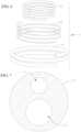
- an exemplary coil-shaped anchoring or docking device 1includes a coiled body 10 having a plurality of turns that extend around a central axis of the docking device 1. At least a portion of the coiled body 10 of the docking device 1 extends helically, with the turns being generally circular and having substantially equal inner diameters.
- the turns of the coiled body 10form an elongate inner space 12 that serves as a landing region or holding region for holding and retaining a prosthetic heart valve when the respective components (e.g., the anchoring or docking device and prosthetic valve, and/or any other components used) are implanted at a valve site, as can be seen, for example, in Fig. 5 .
- the turnscan be circular, elliptical, ovoid, or another shape prior to the implantation of a replacement heart valve.
- a docking devicecan have various numbers of coil turns.
- the number of central, functional, coil turnscan range from just over a half turn (e.g., a half rotation) to 5 turns (e.g., 5 full rotations) or more, or one full turn to 5 turns.
- In the upper, atrial, portion of the docking devicethere can be one-half to three-fourths turn or more.
- the docking device 1is positionable within the native valve, so that at least part of the coiled body 10 extends away from either side of the native valve or an annulus of the native valve.
- part of the coiled body 10is positioned in an atrium, and part of the coiled body 10 is positioned in a ventricle.
- the prosthetic valve that is held in the docking device 1can be implanted at roughly the same position as the native valve, while optionally being supported on both sides of the native valve or of an annulus of the native valve.
- the docking device 1is passed through the native valve in one direction or the other (e.g., from ventricle to atrium, from atrium to ventricle, etc.). Due to the coiled or helical shape of the docking device 1, in some embodiments, a leading or distal end 2 of the docking device 1 can be rotated or inserted through the native valve and into a desired position prior to implantation of the prosthetic valve. For example, for mitral applications, the docking device 1 can be delivered to the mitral position via one of various access sites, for example, transatrially via the left atrium, transseptally through the atrial septum, or via one of various other known access sites or procedures.
- the docking device 1can be inserted transapically or in a retrograde manner.
- the docking device 1can be delivered using access sites to the right atrium (e.g., passing into the right atrium from the IVC or SVC) and/or right ventricle.
- Fig. 3shows an exemplary implantation occurring at the mitral valve via a transseptal delivery method, where an incision or puncture is made in the atrial septum, and a guide sheath 400 and/or a delivery catheter 410 is advanced through the septum and into the left atrium of a patient's heart.
- the guide sheath 400 and/or delivery catheter 410can first be introduced into the patient's venous system by percutaneous puncture and/or by a small surgical cut, for example, at the patient's groin, and then the guide sheath 400 and/or catheter 410 is advanced through the venous system to the right atrium.
- the anchoring or docking device 1can be delivered from the right atrium to the tricuspid valve position, e.g., passing a portion of the docking device 1 through the native valve or a commissure of the native valve.
- a distal end of the delivery catheter 410can be passed from the right atrium through the atrial septum and positioned in the left atrium, with a distal opening of the delivery catheter 400 positioned just above the mitral plane near a desired access point (e.g., a commissure) through which the distal end 2 of the docking device 1 will be advanced into the left ventricle.
- the distal end of the delivery catheter 410is positioned and directed towards commissure A3P3 of the native mitral valve, so that the docking device 1 can be advanced clockwise (i.e., looking in a direction of blood flow or in an inflow to outflow direction) through commissure A3P3 into the left ventricle.
- Other embodiments of docking devicescan be wound or curved in the opposite direction, and instead be advanced through commissure A3P3 in a counter-clockwise direction into the left ventricle.
- the access pointcan instead be commissure A1P1, or any other portion of the opening defined by the mitral annulus, and the advancement can be either clockwise or counter-clockwise, depending on the situation.
- the various docking devices and coils described hereincan be configured to turn/wind either in a clockwise or counter-clockwise direction, even if only shown in the drawing as winding in one direction.
- the guide sheath 400can be introduced and positioned in a desired position (e.g., crossing the septum as shown) prior to the delivery catheter 410, and the delivery catheter 410 can subsequently be inserted through a lumen of the guide sheath 400 and thereby be guided through the vasculature, right atrium, and/or left atrium, or the guide sheath 400 and delivery catheter 410 can be simultaneously introduced and positioned.
- a desired positione.g., crossing the septum as shown
- the delivery catheter 410can subsequently be inserted through a lumen of the guide sheath 400 and thereby be guided through the vasculature, right atrium, and/or left atrium, or the guide sheath 400 and delivery catheter 410 can be simultaneously introduced and positioned.
- the docking device 1While the docking device 1 is held in the delivery catheter 410, the docking device 1 can be straightened to more easily maneuver through the delivery catheter 410 and for a smaller delivery profile. Thereafter, as the docking device 1 is advanced out of the delivery catheter 410, the docking device 1 can return to its original coiled or curved shape (e.g., a pre-set shape-memory shape).
- the docking device 1can exhibit such properties, for example, by being made of or including a shape memory material (e.g., NiTi or another shape memory polymer or alloy), and then being shape set to a desired curvature that the docking device 1 reverts to during delivery.
- a shape memory materiale.g., NiTi or another shape memory polymer or alloy
- the distal end of the delivery catheter 410can also assume a curved configuration with a curvature similar to the curvature of the docking device 1, to ease advancement of the docking device 1 out of the delivery catheter 400.
- the distal end 2 of the docking device 1is then passed through the native mitral annulus (e.g., at a commissure) and into the left ventricle, where it is navigated around to encircle the native leaflets, the chordae tendineae, and any other desired mitral anatomy in the left ventricle, such that any of the native anatomy that is corralled by the docking device 1 will be positioned inside the inner space 12 of the docking device 1 once the docking device 1 has been advanced to a desired position.
- native mitral annuluse.g., at a commissure
- a delivery cathetercan be positioned near an access point (e.g., commissure) of the tricuspid valve and the docking device can be deployed such that it rotates around or encircles the native anatomy of the tricuspid valve.
- the docking devicehas enough flexibility to be pushed through a straight catheter, and enough structure so that it provides a sufficient retention force when deployed.
- the rest of the docking device 1can then be released into another chamber of the heart (e.g., the left atrium, right atrium, etc.).
- Thiscan be accomplished, for example, by rotation of the distal end of the delivery catheter 410 in an opposite direction to the direction of advancement of the docking device 1 (not shown), so that the proximal side (e.g., atrial side) of the docking device 1 can be released without affecting the position of the distal side (e.g., ventricular side) of the docking device 1.
- the stabilization turn/coilcan be released such that it contacts surrounding anatomy (e.g., such that it contacts the walls of a chamber of the heart, atrium walls, walls of the circulatory system or vasculature, etc.) to stabilize or retain the docking device in a desired location/position prior to implantation of the prosthetic valve or THV.
- surrounding anatomye.g., such that it contacts the walls of a chamber of the heart, atrium walls, walls of the circulatory system or vasculature, etc.
- the docking device 1if attached to the delivery catheter by suture, can be released from the delivery catheter 400 by releasing a suture lock as described in U.S. Patent Application No. 14/372953 .
- a long-release suture looped through an opening on a proximal end of the docking devicecan be cut and then pulled to release the delivery catheter from the docking device once it is properly positioned.
- the suturecan be cut or can be pulled through a loop, to release the docking device from the delivery catheter.
- Fig. 4shows a cross-sectional view of a portion of a patient's heart with the docking device 1 at the mitral position and prior to delivery of a prosthetic heart valve.
- the native mitral valvecan still continue to operate substantially normally (or better, e.g., if the docking device helps improve coaptation), so that the patient remains stable.
- the native tricuspid valvecan still continue to operate substantially normally (or better, e.g., if the docking device helps improve coaptation) at a similar stage of implantation in the tricuspid valve position.
- the procedurecan be performed on a beating heart, without the need for a heart-lung machine, which also allows the practitioner more time flexibility to implant the valve prosthesis, without running the risk of the patient being in or falling into a position of hemodynamic compromise if too much time passes between the implantation of the docking device 1 and the later valve implantation.
- a first wire/coil 20e.g., a smaller thickness wire with a larger coil diameter
- a second wire 30/coile.g., a larger thickness wire with a smaller coil diameter
- Fig. 5shows a cross-sectional view of a portion of the heart with both the docking device 1 and a prosthetic valve 40 implanted at the mitral position.
- the prosthetic valve 40can be, for example, an expandable transcatheter heart valve (THV) that is delivered through a catheter in a radially collapsed state, and that is expanded after being advanced to a desired position in the inner space 12 of the docking device 1.
- TSVtranscatheter heart valve
- the guide sheath 400can create a channel through which other devices (e.g., the delivery catheter for delivering the prosthetic valve or THV, etc.) can also be delivered or navigated, e.g., after retraction and removal of the delivery catheter 410 for the docking device 1 from the guide sheath 400.
- the guide sheathcan be retracted and removed as well before a prosthetic valve or THV delivery catheter is navigated to the desired location for delivery of the prosthetic valve or THV.
- a THV or prosthetic valve 40can have an expandable frame structure 41 housing a plurality of valve leaflets 42.
- the expandable frame 41 of the prosthetic valve 40can be balloon expandable, can be self-expanding (e.g., by being made from a shape memory material such as NiTi), or can be expandable in one or more of various other mechanical or non-mechanical ways (e.g., via balloon expansion, etc.).
- a shape memory materialsuch as NiTi
- expandable prosthetic heart valvesThere are numerous types of expandable prosthetic heart valves that would benefit from being anchored within the docking device 1, including those made by Edwards Lifesciences of Irvine, California, Medtronic of Minneapolis, Minnesota and St. Jude Medical of Minneapolis, Minnesota.
- the expandable frame 41pushes radially outwardly and imparts a radially outward force against the docking device, and the docking device applies a radially inwardly directed counterforce against the prosthetic valve 40.
- some of the native anatomye.g., native leaflets, chordae, mitral anatomy, tricuspid anatomy, etc.
- the docking device 1is pinched or squeezed between the docking device 1 and the outer surface of the prosthetic valve 40 when the valve frame 41 is expanded.
- These interactions and opposing forces between the various components and anatomical featuressecurely holds the entire assembly in place at the mitral position or other valve position.
- expansion of a circular prosthetic valvecan cause the docking device coils to become more circular or circular in shape, as they conform to the shape of the prosthetic valve.
- the implantation procedureis then complete, and the delivery tools can be removed from the patient.
- the docking device 1relies on being navigated around and encircling the native leaflets, the chordae tendineae, and/or other parts of the native anatomy (e.g., mitral anatomy, tricuspid anatomy, etc.), which in turn contribute to holding the docking device 1 at a desired height and position at the native annulus (e.g., mitral annulus, tricuspid annulus, etc.).
- the mitral anatomy in an average patientspans approximately 50 mm along a long axis and 38 mm along a short axis.
- the docking devicecan either have a size and dimensions similar to the size of the mitral anatomy (or other valve anatomy), or be adjustable during initial navigation around the mitral anatomy or other valve anatomy (e.g., with an articulable tip, adjustable size and/or shape, etc.), or both.
- the inner diameter of the inner space 12 of the docking deviceshould be sufficiently small (e.g., smaller than an outer diameter of the prosthetic valve 40 in its unbiased expanded state, an example of which is about 29 mm) in order to generate sufficient retention forces between the docking device and the prosthetic valve.
- deploying the docking device 1 as high as possible in the left ventriclealso allows the prosthetic valve 40 to be held higher in the left ventricle.
- an exemplary docking device 1can include a body 10, a first wire/coil 20, and a second wire/coil 30.
- the body 10is formed by an elongate tubular structure.
- the body 10itself can be made with an inherent curvature or coiling, while in other embodiments, the body 10 can be formed generally straight.
- the body 10is made of or includes a flexible or bendable material, for example, ePTFE, such that insertion of a more rigid core, for example, the wires/coils 20, 30, into the body 10 will cause the body 10 to assume or adapt to the shape of the core.
- the body 10is constructed as an ePTFE extrusion that is formed with one or more lumens extending longitudinally through it.
- the body 10can have a cross-section diameter ranging from 0.4 mm to 0.85 mm, or more specifically from 0.6 to 0.85 mm, or in an exemplary embodiment, 0.8 mm.
- the body 10has a dual lumen arrangement, with a first lumen 14 and a second lumen 16 that are aligned in one direction across the cross-section, although in other embodiments, the lumens 14, 16 can be positioned and extend through the body 10 in other arrangements.
- the lumens 14, 16can be formed during extrusion of the body 10, or can be cut into the body 10 after the body 10 has been formed.
- Lumen 14is smaller than lumen 16 (but other sizes and equal sizes are also possible).
- the diameter of smaller lumen 14can range from 0.5 to 4 mm.
- the diameter of lumen 16can range from 0.5 to 4 mm, and have a larger cross-section diameter than lumen 14.
- the body 10has a 2.2 mm diameter, while the lumen 14 has a 0.6 mm inner diameter and the lumen 16 has a 1.0 mm inner diameter.
- the one or more lumen formed in the body 10will be sized and shaped to receive corresponding wires (e.g., wires/coils 20, 30) adapted to be inserted into the body 10.
- the wirescan have a cross-section diameter or thickness that is 0.5 mm to 4 mm, and the diameter/thickness of the wire can be smaller than the cross-section diameter/thickness of the lumen through which it is to be inserted.
- the cross-sectional diameter/thickness of wire 20 which can be inserted into lumen 14can be 0.5 to 4 mm in diameter/width
- the cross-section diameter/thickness of wire 30can be 0.5 to 4 mm in diameter/width, to be inserted into lumen 16.
- the cross-section diameters/dimensions of each of the lumenscan be at least as great as or greater than the cross-section diameter of the wire being inserted into the lumen.
- the lumencan stretch or expand to accommodate a larger wire cross-section.
- the docking device 1further includes a first wire/coil 20 and a second wire/coil 30.
- the body 10 and wires 20, 30are shown in Fig. 6 as turning or wrapping in a counter-clockwise direction from top to bottom (or in an inflow to outflow direction), but the body 10 and wires 20, 30 can also be configured to turn/wrap in a clockwise direction.
- the wires 20, 30can each be made of or include one or more shape memory materials, such as NiTi, and can be shape set, for example, to form coils with differently sized curvatures. Other shape memory metals can be used. Non-shape memory materials can also be used, such as stainless steel.
- the first wire 20is shape set to form a coil having a larger inner curvature or coil diameter compared to the second wire 30, for example, ranging from 20 to 40 mm, or more specifically, 35 mm, and can be made to have a thinner cross-sectional thickness than the second wire 30, for example, 0.5 mm, or alternatively or in addition to having a thinner cross-section, can be formed with a lower modulus of elasticity than the second wire 30.
- the second wirecan be shape set to form a coil with a smaller inner curvature or coil diameter than the first wire 20, for example, ranging from 15 to 30 mm, or more specifically, from 20 to 30 mm, or more specifically, 25mm, while having a larger cross-sectional thickness, for example, 0.8 mm, and/or a higher modulus of elasticity than the first wire 20.
- the body 10 of the docking device 1only has the first wire 20 inserted therein, and extending, for example, through lumen 14, while lumen 16 remains empty.
- This arrangementdefines a first stage or configuration of the docking device 1.
- insertion of the first wire 20can be from either end of the body 10, while in other embodiments, one end of the lumen 14 can be closed, such that insertion of the first wire 20 can only be from one side of the body 10.
- Initial insertion of the first wire 20 through body 10causes the body 10 to substantially assume the shape and size of the first wire 20 or a shape having a diameter that is less than an initial diameter of the body, but that can be equal to, more than, or less than an initial diameter of the first wire 20.
- the body 10 in the instant exampleassumes a coil shape with an inner diameter of about 35 mm.
- This larger initial size of the docking device 1is maintained during advancement of the docking device 1 around the native anatomy (e.g., mitral anatomy, tricuspid anatomy, etc.) to a desired position relative to the native valve, in order to assist in easier navigation around and capturing of the native anatomy (e.g., mitral anatomy, tricuspid anatomy, etc.).
- the thinner thickness and/or lower modulus of elasticity of the wire 20also allows the docking device 1 to be more flexible in the first configuration, which also makes it easier to navigate the distal end of the docking device 1 through and/or around the leaflets, chordae tendineae, and/or other anatomical geometry.
- a proximal region of the first wire 20can further be shape set to form a coil having a larger diameter than other portions of the first wire 20, for example, 55 mm (not shown).
- This enlarged proximal region of the first wire 20would correspond to a portion of the docking device 1 that is positioned in a first chamber of the heart (e.g., the left atrium, right atrium, etc.) when the docking device 1 is advanced to a desired position at the native annulus (e.g., mitral annulus, tricuspid annulus, etc.), and can help reduce or prevent sliding or other migration of the docking device 1 into a second chamber of the heart (e.g.
- the left ventricle, right ventricle, etc.after placement, for example, by sitting at the bottom of the first chamber (e.g., left atrium, right atrium, etc.) and forming an abutment against a floor of the first chamber (e.g., left atrium, right atrium, etc.), or by pressing against the lateral walls of the first chamber (e.g., lateral atrial walls, etc.).
- the first chambere.g., left atrium, right atrium, etc.
- abutment against a floor of the first chambere.g., left atrium, right atrium, etc.
- lateral walls of the first chambere.g., lateral atrial walls, etc.
- the second wire 30can be inserted into the body 10, for example, through a proximal opening of the larger lumen 16, to adjust the docking device 1 to a smaller second state or configuration.
- the first wirecan be removed from the body 10 prior to or after inserting the second wire, or the first wire can remain in the body 10 with the second wire. Where the first and second wire are both in the body 10, due to the greater thickness and/or higher elastic modulus of the second wire 30, the tension that the second wire 30 applies to the body 10 is greater than and overcomes the tension that the first wire 20 applies to the body 10.
- the body 10is urged by the second wire 30 to assume or get closer to the smaller shape set dimensions of the second wire 30.
- the inner space 12 of the docking device 1therefore assumes a smaller functional diameter (which can be equal to, more than, or less than the diameter of the second wire coils; for example, it can assume an approximately 25 mm inner diameter) based on the shape set size of the second wire 30.
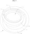
- Fig. 9shows a perspective view of the docking device 1, where the second wire 30 has been partially inserted into the body 10 during an adjustment or transition of the docking device 1 from the first configuration to the second configuration.
- a size of a top or proximal portion 18a of the body 10, into which the second wire 30 has already been advanced,has been brought down or reduced to a smaller diameter.
- a size of a bottom or distal portion 18b of the body 10remains at the larger diameter corresponding to the size of the first wire 20, since the second wire 30 has not yet reached and does not yet extend through the distal portion 18b.
- Fig. 10shows a top perspective view of the docking device 1, where the second wire 30 has been fully inserted into the body 10, and where the docking device 1 has therefore been completely adjusted to the second size configuration.
- the docking device 1assumes a coiled shape with an inner diameter of approximately 25 mm.
- dashed lines 22are also shown in Fig. 10 to show the original coil size (e.g., a 35 mm coil size) of the docking device 1 when the docking device 1 was in the first size configuration.
- the coils of a docking devicecan change shape by having a tension wire attached to the distal end, as described in U.S. Provisional Patent Application Serial No. 62/395,940 and US. Patent Application No. 15/682,287 . Pulling on the tension wire increases the tension and tightens the coils of the docking device.
- the diameter of the docking device 1(or the diameter of inner space 12 or the functional turns/coils of the docking device) should be smaller than an outer diameter of the prosthetic valve in its expanded state.
- the relative diameters of the valve and the docking device 1are important as they directly control the retention forces that are generated between the components when the valve is expanded, where a smaller coil diameter of the docking device 1 will generally lead to a larger retention force between the parts.
- a second wire with an appropriate sizeshould be selected based on a size of the valve to be implanted.
- a 25 mm diameter second wire 30can be used, for example, with a replacement valve with an approximately 29 mm expanded diameter.
- a smaller diameter shape set second wirecan be used, for example, a second wire with a 23 mm to 24 mm inner space diameter.
- other differently sized second wirescan be selected and used instead.
- the spring force of the entire docking device 1is also increased when the docking device 1 is in the second configuration (e.g., equal to the sum of the spring force of individual wires 20, 30), for example, when compared to other docking devices that have only a single wire core.
- the docking device 1can also improve the retention of the docking device 1 at a desired position relative to the native valve before the prosthetic valve is delivered, for example, by more tightly sandwiching leaflets and other anatomy between coils of the docking device and/or between the coils of the docking device and the prosthetic valve, thereby reducing unintended migration of the docking device 1 (e.g., towards the left ventricle or another chamber).
- a proximal region of the second wire 30can also further be shape set to have a larger diameter than other portions of the second wire 30 (not shown). This can be done to further hold the docking device 1 in place and to deter migration of the docking device 1 (e.g., into the left ventricle or an undesired location) after placement.
- the proximal region of the second wire 30can be shape set to have an inner space or functional diameter of 55 mm to match a 55 mm diameter of a similar enlarged proximal region of first wire 20, and would serve a similar function, where the enlarged proximal region(s) are positioned in the left atrium and form an abutment against a floor and/or wall of the first chamber of the heart (e.g., left atrium, right atrium, etc.) against further movement of the docking device 1 into the second chamber (e.g., left ventricle, right ventricle, etc.).
- a floor and/or wall of the first chamber of the hearte.g., left atrium, right atrium, etc.
- the docking device 1e.g., left ventricle, right ventricle, etc.
- the docking device 1may only have one wire (e.g., wire 20 or 30) with an enlarged proximal region, and not the other.
- the docking device 1can have only one lumen and each of the wires (e.g., two wires) is interested into the same lumen sequentially (e.g., one wire can be removed and the other inserted, or the second wire can be inserted next to the first wire).
- a two-stage adjustable docking devicethat facilitates both easier delivery of the docking device itself and a more secure docking site for a prosthetic valve.
- similar performancecan be achieved by first advancing a wire core 50 to a desired position at the native valve site, and then advancing a stiffer tube 60 over the wire.
- the wirecan be made of or include a shape memory material such as NiTi, and can be shape set to have a relatively larger coil diameter for initial delivery to the valve site.
- the wirecan also be made relatively thin and/or flexible.
- the tubecan also be made of or include a shape memory material such as NiTi, can be shape set to have a smaller coil diameter than the wire, and can be made thicker and/or stiffer than the wire, such that the shape of the tube can overcome any resiliency in the shape of the wire.
- the tubecan be slid or otherwise advanced over the wire to reduce the size of the coil assembly, such that an inner space defined by the coiled shape of the combined docking device assumes a smaller final inner diameter for receiving the prosthetic valve.
- a tubecan first be advanced at the valve site, and then a wire can be inserted into the tube to reduce a size of the combined assembly.
- the tubecan be made of or include, for example, a thermoplastic that is co-extruded with an ePTFE lumen, and that can assume a shape that can more easily be maneuvered around the mitral or other valve anatomy.
- a wirethat is made of or includes a shape memory material such as NiTi can be inserted into the tube.
- the wirecan be shape set to have a coil shape with a relatively smaller diameter compared to the tube, and can be made thicker and/or otherwise stiffer, so that when the wire is inserted into the tube, the wire is sufficiently strong to affect the shape of the tube and to reduce the combined docking device to a smaller coil size for receiving the prosthetic valve.
- the diameter of the circular turns of a second wire coil inserted into the tube of the docking devicecan be smaller than the diameter of the circular turns of the first wire coil.
- the diameter of the first coil wirecan range from just as big as the second wire coil diameter to ten times the diameter of the second wire coil.
- the first wire coilcan have a diameter that is twice as big as the diameter of the second coil, four times as big, or ten times as big.
- the force applied by the coilis relative compared to the outward force applied by a replacement valve once the replacement valve has expanded.
- the replacement valvecan be an Edwards SAPIEN 3 transcatheter heart valve, or it can be another replacement heart valve.
- the radial force of the docking devicecan be five (5) to twenty (20) times that of an expanded replacement valve.
- the radial force of the docking devicecan be five (5) to ten (10) times that of the expanded replacement valve.
- the sizes and shapes of the tubes, wires, and other components described in the above embodimentsare only examples, and different sized components can be selected for both advancement of the docking device to the valve site as well as for final docking of a replacement valve, based for example, on different sized patient anatomies and replacement valves selected, among other factors.
- a docking devicein embodiments of the invention where a docking device is deployed in a two-stage process similar to that described above, delivery of the docking device can be more easily facilitated, and performance of the docking device can be improved. Delivery of a distal end of the docking device into a chamber of the heart (e.g., the left ventricle, right ventricle, etc.) while the docking device is in a larger and more flexible first configuration allows for easier navigation through and/or around the native valve anatomy. Then, adjustment of the docking device to a second configuration where the docking device has a smaller inner diameter and/or an increased spring force provides for a stronger and more secure docking site for a prosthetic valve that is expanded and/or otherwise held in the docking device.
- a chamber of the hearte.g., the left ventricle, right ventricle, etc.
- an atrial or proximal side of a coiled or spiral docking devicecan be enlarged, for example, to a size that is similar to the anatomy of an atrium.
- the proximal or atrial coilcan be enlarged to a range of 30 mm to 80 mm, or to a range of 30 mm to 75 mm, or to approximately 55 mm, to prevent or block the docking device from movement towards the left ventricle or right ventricle.
- the enlarged portion of the docking devicecan abut against a floor of the atrium (e.g., left atrium or right atrium) or push against lateral atrial walls, thereby steadying or stabilizing the docking device relative to the native anatomy (e.g., mitral anatomy, tricuspid anatomy).
- the atrial, or proximal portion, of the coilcan be referred to as the stabilization turn/coil or the atrial turn/coil.
- a main coilis enlarged at the atrial or proximal end
- such enlargement of the main coil of the docking devicecan result in a less stable connection between the docking device and the prosthetic valve, for example, due to a reduction in the contact area between the components, at least in regions where the docking device has an enlarged region/turn.
- a transcatheter heart valvethat has a 29 mm expanded and unbiased diameter can be docked in a coiled anchor with a 23 mm to 24 mm inner diameter to generate a sufficient retention force between the components after the replacement valve is expanded in the docking device.
- the enlarged portions of the docking devicemay no longer contribute to retention of the replacement valve therein.
- Fig. 11shows a perspective view of an exemplary docking device
- Fig. 11Ashows a cross-sectional view of the docking device of Fig. 11 positioned at a native mitral annulus of a heart.
- the docking device 100includes a distal or ventricular portion 110 made up of a single coil, and a proximal or atrial portion 120 with a first inner coil 122 and a second outer coil 124 (which is configured as a stabilization turn/coil).
- the coils/turns of this docking device(and the other docking devices described herein) can be configured to turn/wind in a clockwise or counter-clockwise direction.
- the distal portion 110 and the inner coil 122 of the proximal portion 120together form a main coil of the docking device 100 that has a substantially constant inner diameter and that forms a docking site for a prosthetic valve.
- an embodiment of the docking device 100can be formed to have a small and substantially constant winding inner diameter of about 23 mm to 24 mm to tightly and securely hold the prosthetic valve after the prosthetic valve is deployed.
- Other embodimentscan have coils with inner diameters that are less than 23 mm or more than 24 mm, depending for example, on the size of the prosthetic valve and on an amount of retention force desired, among other factors.
- the outer coil 124 of the proximal portion 120serves as a secondary coil that emerges from the main coil to form a separate spiral or coil structure.
- the outer coil 124extends around an outside of the inner coil 122, and extends radially outwardly wider than both the inner coil 122 and the distal portion 110 of the docking device 100. As can be seen in Fig.
- the outer coil 124 and the inner coil 122are both configured to extend into a chamber or atrium of the heart (e.g., the left atrium or right atrium) when the docking device 100 is advanced to a desired position relative to the native valve (e.g., mitral valve, tricuspid valve), and is sized and shaped to be sufficiently large or wide to effectively serve as a transient anchoring and stabilizing mechanism (or stabilization coil/turn) for the docking device 100 prior to delivery of the prosthetic valve.
- the native valvee.g., mitral valve, tricuspid valve
- the outer coil 124is integrally formed with the distal portion 110 and the inner coil 122 of the proximal portion 120, and extends away from the main coil of the docking device 100 at or near a middle or central region of the docking device 100, forming a fork or split 118 in the docking device 100.
- a position of the split/fork 118 of the docking device 100corresponds substantially to or can be just proximal to a portion of the docking device 100 that passes through the native valve (e.g., mitral valve, tricuspid valve, etc.) when the docking device 100 is delivered to the native valve.
- the larger or wider shape and dimensions of the outer coil 124can form an abutment that blocks or prevents advancement or migration of the docking device 100 (e.g., towards the left ventricle, right ventricle, etc.).
- the outer coil 124can also be wide enough to push radially outwards against lateral portions of the atrial wall, thereby providing further stability to the docking device 100.
- Figs. 12 and 12Aillustrate an embodiment similar to that in Figs. 11 and 11A , but instead of a rectangular cross-section as in Figs. 11 and 11A , the cross-sections of the inner coil 122 and outer coil 124 in the proximal portion, and the distal portion 110, are circular.
- Fig. 13shows a perspective view of an exemplary docking device.
- the docking device 200 in Fig. 13can have a same or similar general gross geometry as the docking device 100 in Figs. 11, 11A , 12, and 12A , but is instead constructed using a first coil 210 and a separate second coil 220.
- the first coil 210serves as a main coil for the docking device 200, and can have size and shape properties similar to the main coil of the docking device 100 in Figs. 11, 11A , 12, and 12A (e.g., the first coil 210 can have a substantially constant inner diameter of about 23 mm to 24 mm).
- the first coil 210provides a main docking site for the prosthetic valve, and can therefore be made thicker and/or more rigid compared to the second coil 220.
- the second coil 220serves as a secondary coil for the docking device 200, and begins and is secured to or otherwise attached to the first coil 210 at or near a distal or ventricular end 202 of the docking device 200.
- the two coils 210, 220 of docking device 200start at approximately the same point at the distal end 202 of the docking device 200.
- the two coilsmay not extend a same length in the distal direction, for example, the second coil 220 may not extend as far distally as the first coil 210.
- the second coil 220then splits from and extends away from the first coil 210 at or near a middle or central region of the docking device 200.
- the two coils 210 and 220can be connected together in a variety of ways, e.g., by weld, adhesive, or bonded together, or connected by a heat shrink method.
- the two coils 210 and 220can be from the same piece, where the second coil 220 is cut away from the main piece, and the main piece is the first coil.
- the second coil 220is configured as a stabilization coil/turn to temporarily anchor and stabilize the docking device 200 at the implantation site prior to delivery of the prosthetic valve. Since the second coil 220 is not used as a docking site for the prosthetic valve, the second coil 220 can be constructed thinner and/or more flexible or floppy when compared to the first coil 210.
- the additional flexibility in the second coil 220can also potentially help better stabilize the docking device 200, for example, by allowing the shape of the second coil 220 to better conform to a shape of the surrounding anatomy (e.g., to atrial walls) it comes into contact with, and/or by acting as a damping element against movement of the docking device 200 relative to the native valve annulus.
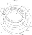
- Fig. 14shows a perspective view of an exemplary docking device.
- the docking device 300 in Fig. 14also has a first coil 310 and a second coil 320.
- the first coil 310serves as a main coil for the docking device 300 and as a main docking site for the prosthetic valve. Therefore, similarly as seen with the docking device 200 in Fig. 13 , the first coil 310 of the docking device 300 is also be made thicker and/or more rigid compared to the second coil 320.
- the second coil 320acts as a secondary coil for the docking device 300, and is configured as a stabilization coil/turn to temporarily anchor and stabilize the docking device 300 relative to the native valve prior to delivery of the prosthetic valve.
- the second coil 320is attached to the first coil 310 at or near a proximal or atrial end 304 of the docking device 300, where the proximal ends of the two coils 310, 320 can be crimped or welded together, or otherwise connected to one another, at a connection portion or region 330.
- the second coil 320is not connected to and does not extend together with the first coil 310 for any appreciable distance along the length of the docking device 300. Instead, the second coil 320 splits from the first coil 310 at or near the proximal end 304 of the docking device 300, near where the two coils 310, 320 are connected. From the proximal end 304 of the docking device 300, the second coil 320 extends in a coil or spiral shape towards a distal end 302 of the docking device 300, and extends radially outwardly wider than the first coil 310.
- the second coil 320is shorter axially than the first coil 310, and has a distal end 322 that terminates at or near a middle or central region of the docking device 300 as a whole, which can in some embodiments correspond substantially to a height at which the floor of a chamber or atrium of the heart (e.g., the left atrium or right atrium) will be positioned when the docking device 300 is delivered to the native valve.
- the distal end 322 of the second coil 320can, in some embodiments, abut against the floor of the chamber or atrium (e.g., left atrium or right atrium) to prevent or hinder movement of the docking device 300 towards another chamber or ventricle (e.g., the left ventricle or right ventricle).
- the second coil 320can be made thinner and/or more flexible or floppy than the first coil 310, to potentially further aid in stabilizing and/or damping movement of the docking device 300 at the implant site prior to delivery of the prosthetic valve.
- the two coilscan be the same or vary in thickness from one another based on the particular usage of the coil, and can in some embodiments also vary in material, cross-sectional shape, and/or other physical properties, depending on the particular applications and needs.
- the connections between the coilscan be achieved by crimping, for example with a crimp tube, by welding, adhesion, or by any other appropriate connecting or joining technique.
- a secondary coil of the double coilcan help temporarily anchor and/or stabilize the docking device prior to expansion or docking of a prosthetic valve therein, by pushing or abutting against the atrial floor and/or lateral atrial walls, thereby reducing relative motion between the docking device and the surrounding native tissue. In this manner, abrasions and/or tears of the native valve leaflets and other valve anatomy caused by relative motion or rubbing between the native tissue and the docking device can be reduced or prevented.
- a main coil of the double coilincluding portions of the main coil positioned in the left atrium, remain and retain a small inner diameter, in order to continue to provide an effective docking site for the prosthetic valve along a greater length of the docking device.
- the docking devicecan be a laser hypo tube with a wire run through it, as described in U.S. Provisional Application Serial No. 62/395,940 and US. Patent Application No. 15/682,287 .
- the coilcan be a shape memory metal that changes shape when its temperature increases.
- the docking devicescan be covered in an additional layer such as a fabric or textile to reduce damage to the native tissues.
- a cover that is made of or includes, for example, a high friction material that generates additional frictional forces, to increase retention forces between the docking device and a docked prosthetic valvecan be included.
- the use of a high friction material for the coverprovides an increased amount of friction generated between the valve and the covering to hold a shape of the docking device and prevent the docking device from unwinding when the expandable valve is expanded in the docking device.
- a cover 1180that can be made from one or more high friction materials that can be placed over the tubular body 1130.
- the cover 1180is made of or includes a PET braid.
- the ePTFE tubular bodyis porous, providing a cushioned, padded-type layer for struts or other portions of a frame of the expandable valve to dig into, improving engagement between the valve and the docking device 1100.
- the PET layer 1180provides additional friction against the native valve leaflets when the prosthetic valve is expanded and the struts or other portions of the valve frame apply outward pressure on the docking device 1100.
- the cover 1180can be made from one or more other high friction materials that covers the tubular body of the docking device 1100 in a similar manner.
- the docking device 1can also include barbs or anchors 90, as illustrated in Fig. 9A , further increase retention forces.
- the barbs or anchors 90can be in the shape of small cleats or hooks or other shape that serves to hold the docking device 1 in place within the native tissue.
- the barbs/anchors 90extend radially outward from an outer surface and/or the ends of the tubular body of the docking device.
- an outer surface of a frame of the replacement valvecan also be covered in a cloth material or other high friction material to further increase the friction force between the docking device and the valve, thereby further reducing or preventing the docking device from unwinding.
- the tubular body in some embodimentscan also or instead be made of or include a material that promotes more rapid tissue ingrowth, and can be constructed to have a larger amount of surface area, for example, with a VALURE TM film, to further bolster tissue ingrowth.
- the tubular bodycan be made from ePTFE and can be constructed with, for example, a 30 micron pore size, to facilitate easier anchoring of blood cells in and against its outer surface, for example, to promote in-growth of tissue after implantation.
- the porescan range from 30 to 100 microns in size, to increase the surface area for cells to embed within and to increase tissue growth.
- ePTFEis also a very low friction material that is useful with respect to preventing or minimizing trauma to tissue with which it comes into contact.
- Tissue growthcan be promoted by using a material with a high surface area or by increasing the available surface area for ingrowth, and an increased surface area can be imparted/included in a variety of ways to promote tissue ingrowth, e.g., with pores, braided material, woven material, etc..
- tissue ingrowthe.g., with pores, braided material, woven material, etc.
- some or all of the features from one or more of the embodiments described abovecan be combined to form still other docking device embodiments.
- a lower friction surface or cover 1170 on the upper and lower coilscan assist with deployment and provide a smoother insertion of the docking device 1100 and a higher friction surface in the central region can assist with holding the docking device in place. Therefore, as seen in Fig. 15 , an additional braid layer 1180 can be added to the central region 1110 of the docking device 1100.
- the braided layer or other high friction layer 1180provides additional friction against the THV when the THV is expanded in the docking device 1100.
- the friction that is formed at the interfaces between the inner surface of the central region 1110 of the docking device 1100, the native mitral leaflets, and the outer surface of the THVcreates a more secure locking mechanism to more strongly anchor the THV and the docking device 1100 to the native annulus.
- the braid layercan be limited to extend across only the central coils of the docking device 1100 so that the upper region 1130 and lower region 1120 of the docking device 1100 remain lower friction.
- the braidingcan also provide a larger surface area for promotion of tissue ingrowth. While cover 1180, surface/cover 1170, and other features/characteristics are described with respect to device 1100, these can be incorporated in the same or similar ways into the docking devices described elsewhere herein.
- docking deviceshave generally been discussed above and examples have been given with respect to anchoring replacement valves at the mitral position.
- the docking devicesas described or slightly modified versions thereof, can also be applied in similar manners to valve replacements at other valve sites as well, for example, at the tricuspid or aortic positions (e.g., to treat insufficiency issues).
- the docking devicescan similarly be made of or include a shape memory material, such as Nitinol, and/or a non-shape memory material.
- valve annulimay be rounder or more circular in shape than the mitral valve annulus
- patients that are diagnosed with insufficiencies at either positionnevertheless exhibit enlarged annuli that both prevent the native leaflets from properly coapting, and that also can cause the annuli to become too large, too soft, or too otherwise diseased to securely hold an expandable valve therein. Therefore, use of a rigid or semi-rigid docking device can also be beneficial for anchoring a replacement valve at those valve sites as well.
- docking devicesWhen applied to valves other than the mitral valve, docking devices can also provide a more secure landing zone at those sites as well.
- the docking devices and replacement valvescan be applied similarly as has been discussed with respect to implantation at the mitral valve.
- a possible access point for tricuspid replacementcan be, for example, transseptal access, while a possible access point for aortic replacement can be, for example, transfemoral access, although access to the respective valve sites is not limited thereto.
- coil-shaped docking devicesas previously described at the other valve sites also serves to circumferentially cinch or clamp the native leaflets between coils of the docking device after deployment of the replacement valve at the native annulus, which further prevents or reduces slipping or other movement of the docking device and of the sandwiched tissue relative to the docking device, and prevents unwanted growth or expansion of the native annulus over time.
- the docking devices described hereincan also be used alone to treat the native valve insufficiency.
- the coils described hereincan be the final implant to treat tricuspid valve insufficiency.
- the devicecan be delivered behind the leaflets and chords in the right ventricle, and reduce the diameter of the orifice. The orifice is reduced since the native tricuspid valve leaflets are attached at the annulus on one side, and the chordae on the ventricular side. Part of the device sits in the right atrium to help anchor or hold the device in place as previously described.
- the portion that sits in the right ventricleis sized so as to reduce the valve annulus to a desired diameter.
Landscapes
- Health & Medical Sciences (AREA)
- Cardiology (AREA)
- Engineering & Computer Science (AREA)
- Biomedical Technology (AREA)
- Life Sciences & Earth Sciences (AREA)
- Public Health (AREA)
- Heart & Thoracic Surgery (AREA)
- Vascular Medicine (AREA)
- Oral & Maxillofacial Surgery (AREA)
- Animal Behavior & Ethology (AREA)
- General Health & Medical Sciences (AREA)
- Transplantation (AREA)
- Veterinary Medicine (AREA)
- Prostheses (AREA)
- External Artificial Organs (AREA)
- Vehicle Body Suspensions (AREA)
- Burglar Alarm Systems (AREA)
- Surgical Instruments (AREA)
Description
- This application claims priority to
U.S. Provisional Patent Application Serial No. 62/380117, filed on August 26, 2016 U.S. Provisional Patent Application Serial No. 62/395940, filed on September 16, 2016 U.S. Patent Application No. 14/372953, entitled "Mitral Valve Docking Devices, Systems, and Methods," filed on July 17, 2014 US. Patent Application No. 15/682,287, filed on August 21, 2017 - The invention generally relates to medical devices and procedures pertaining to prosthetic heart valves. More specifically, the invention relates to the replacement of heart valves that may be dysfunctional or have malformations. Embodiments of the invention relate to an anchoring or docking device that can hold and maintain a positioning of a prosthetic heart valve therein, to replace the function of a native heart valve, for example, for a mitral or tricuspid valve replacement procedure. Embodiments of the invention also relate to implantation procedures associated with such anchoring or docking devices, or with assemblies including such an anchoring device and the prosthetic heart valve. The invention relates to a docking device for docking a prosthetic valve at a native heart valve as disclosed by appended
claim 1. - Referring first to
Figs. 1 and 2 , themitral valve 50 controls the flow of blood between theleft atrium 52 and theleft ventricle 54 of a human heart. After theleft atrium 52 receives oxygenated blood from the lungs via the pulmonary veins, themitral valve 50 permits the flow of the oxygenated blood from theleft atrium 52 into theleft ventricle 54. Subsequently, theleft ventricle 54 contracts, and the oxygenated blood that is being held in the left ventricle is delivered through theaortic valve 56 and theaorta 58 to the rest of the body. Meanwhile, during this ventricular contraction, the mitral valve should close to prevent any of the blood that was being held in the left ventricle from flowing back into the left atrium. - When the left ventricle contracts, the blood pressure in the left ventricle increases substantially, which serves to urge the mitral valve closed. Due to the large pressure differential between the left ventricle and the left atrium during this time, a large amount of pressure is placed on the mitral valve, leading to a possibility of prolapse, or eversion of the leaflets of the mitral valve back into the left atrium. To prevent this, a network of
chordae tendineae 62 connects the leaflets of the mitral valve to papillary muscles located on the walls of the left ventricle, where both the chordae tendineae and the papillary muscles are tensioned during ventricular contraction to hold the leaflets of the mitral valve in the closed position and to prevent them from turning inside-out and extending back towards the left atrium, thereby preventing backflow of the oxygenated blood into the left atrium. The network ofchordae tendineae 62 is schematically illustrated in both the heart cross-section ofFig. 1 and the mitral valve ofFig. 2 , the latter of which also shows a general shape of the mitral valve and its leaflets as viewed from the left atrium.Commissures 64 are located at the ends of themitral valve 50 where theanterior leaflet 66 and theposterior leaflet 68 come together. - Various complications of the mitral valve and other valves can cause potentially fatal heart disease. One form of valvular heart disease is mitral valve leak or mitral regurgitation, characterized by an abnormal leaking of blood from the left ventricle through the mitral valve back into the left atrium. This can be caused, for example, by dilation of the heart, weakening of the chordae tendineae and/or the papillary muscles, or by damage to the native leaflets. In these circumstances, it can be desirable to repair the native valve or to replace the functionality of the native valve with that of a prosthetic heart valve.
- With respect to mitral valve replacement, historically there has been less research and development directed towards commercially available ways to replace a mitral valve through a transcatheter approach and/or other minimally or less invasive procedures. Mitral valve and tricuspid valve replacement can be more difficult than aortic valve replacement in many respects, for example, due to the non-circular physical shape of the mitral valve, its sub-annular anatomy, and more difficult access to the valve due to its position deeper in the heart.
- It could be beneficial to use prosthetic aortic valves or similar circular or cylindrical valve prostheses for mitral and tricuspid valve replacements as well. However, one issue with replacing mitral valves in this manner is the size and non-circular shape of the native mitral annulus, as seen in
Fig. 2 . Aortic valves are more circular in shape, so prosthetic transcatheter aortic valves also have more circular or cylindrical valve frames. Further, in many aortic valve replacement cases, the need for valve replacement arises from aortic valve stenosis, where the aortic valve narrows due to calcification or other hardening of the native leaflets. Therefore, in these cases, the aortic annulus generally provides a naturally circular, compact, and stable anchoring site for prosthetic valves. - On the other hand, the mitral and tricuspid valves are both larger than the aortic valve, and more elongate in shape, making them more difficult and unconventional sites for implanting a replacement valve with a generally circular or cylindrical valve frame. A circular prosthetic valve that is too small can result in leaking around the implant (i.e., paravalvular leakage) if a good seal is not established around the valve, while a circular prosthetic valve that is too large can stretch out and damage the narrower parts of the native mitral annulus.
- Another prominent obstacle to effective mitral valve replacement stems from the large cyclic loads that the replacement valve will be subjected to, and the need to establish a sufficiently strong and stable anchoring or retention of the prosthetic valve in the mitral annulus that can withstand such forces without dislodging, especially from heart movement and/or pressures applied on the implant during ventricular contraction. In addition, such movement and rhythmic loads can easily fatigue the implant, leading to fractures or other damage to the valve. And if the valve prosthesis manages to remain held at the mitral position, even a slight shift in the alignment of the valve can still lead to blood flow through the valve or other parts of the heart (e.g., left ventricular outflow tract) being obstructed or otherwise negatively impacted..
US 2015/0230921 A1 discloses a coiled anchor for docking a mitral valve prosthesis at a native mitral valve of a heart has a first end, a second end, and a central axis extending between the first and second ends, and defines an inner space coaxial with the central axis. The coiled anchor includes a coiled core including a bio-compatible metal or metal alloy and having a plurality of turns extending around the central axis in a first position, and a cover layer around the core, the cover layer including a bio-compatible material that is less rigid than the metal or metal alloy of the coiled core. - One way to apply existing circular or cylindrical transcatheter valve technology to non-circular valve replacement (e.g., mitral valve replacement) is to use an anchoring or docking station or other docking device that forms or otherwise provides a more circular docking site at the native valve position to hold the prosthetic valve. Existing expandable transcatheter valves that were developed for the aortic position, or similar valves that have been slightly modified to more effectively replicate valve function other than aortic valve function, can then be more securely implanted at the native valve position using such docking stations. Such docking stations can first be positioned at the native valve annulus, and thereafter, the valve implant can be advanced and positioned through the docking station while in a collapsed configuration, and can then be expanded, for example, via balloon expansion, self-expansion (e.g., when the frame is made of a shape memory material, such as NiTi), or mechanical expansion, so that the frame of the valve implant pushes radially against the docking station to hold the valve implant in place. Preferably, the docking station can be delivered using minimally or less invasive techniques, such as the same or similar transcatheter approaches used to deliver the valve implants, so that the docking device and the valve implant do not need to be delivered using completely separate and/or independent procedures.
- It would therefore be desirable to provide devices and methods for facilitating the docking or anchoring of such replacement valves. Embodiments herein provide a stable docking station or docking device for retaining a prosthetic valve. Other features are provided in order to improve or ease the delivery of the docking device, to hold a desired position of the docking device after it has been advanced to a desired position at the implant site and prior to delivery of the prosthetic valve, and/or to improve retention of the prosthetic valve by the docking device after expansion of the valve therein. Such docking devices and methods can, in some instances, be used in the mitral position, but can also be used for other valve replacement procedures, for example, for tricuspid, pulmonary, or aortic valve replacements, to provide for more secure and robust anchoring and holding of valve implants at the native annuluses at those positions as well.
- Docking devices for docking a prosthetic valve or valve prosthesis at a native valve of a heart and systems including such docking devices are disclosed. Docking devices can include a flexible body with one or more lumens extending through the flexible body (for example, a first lumen extending through the flexible body and a second lumen extending through the flexible body). The docking device(s) can also include one or more coils (for example, a first coil and a second coil). The flexible body can have a tubular structure and the one or more lumens (e.g., the first lumen and the second lumen) can each extend fully or at least partially through the flexible body. The flexible body or tubular structure can have at least one full or partial central turn, have another shape, or have no particular pre-set shape (e.g., a simple straight tube). The one or more lumens can each have one or more cross-sectional dimensions (e.g., area, diameter, width, etc.). For example, the first lumen can have a first cross-sectional area and the second lumen can have a second cross-sectional area.
- The one or more coils can be more rigid than the flexible body and can each be configured to fit within one of the one or more lumens. The one or more coils can each have a plurality of circular turns that each define a diameter (e.g., a coil diameter or diameter of an inner space partially or fully circumscribed by one or more of the turns), which diameter can be the same as or different from diameters of other coils. For example, when a first coil and a second coil are used, the first coil can be more rigid than the flexible body, can be configured to fit within the first lumen, and can have a plurality of circular turns that define a first diameter. Similarly, the second coil can also be more rigid than the flexible body, can be configured to fit within the second lumen, and can have a plurality of circular turns that define a second diameter, which is less than the first diameter.
- The docking devices and coils described herein can each have multiple configurations, e.g., straightened or elongated delivery configurations, unconstrained or relaxed configurations, deployed or implanted configurations, transition configurations, combinations of these, etc.) and the configurations can have different shapes, sizes, diameters, etc.
- For example, a docking device can have at least a first configuration and a second configuration. In one example, the first configuration can be adopted or formed when the first coil is inserted through or positioned within (e.g., fully or at least partially within) the first lumen. In this first configuration the flexible body or docking device can define or have a third diameter (e.g., a coil diameter or diameter of an inner space partially or fully circumscribed by the flexible body or docking device). The second configuration can be adopted or formed when the second coil is inserted through or positioned within (e.g., fully or at least partially within) the second lumen. In this second configuration the flexible body or docking device can define or have a fourth diameter that is less than the first diameter and/or greater than the third diameter. In the first configuration, the third diameter can be greater than or equal to the first diameter (or less in some circumstances). In the second configuration, the fourth diameter can be less than the first diameter and greater than or equal to the second diameter (or less than the second diameter in some circumstances).
- Any of the docking device(s), coils, and/or flexible bodies herein can also have an upper turn. The upper turn can be configured to extend in a proximal direction from other turns (e.g., from the plurality of turns). The upper turn(s) can be configured as a stabilization turn/coil to help prevent migration of the docking device (e.g., after implantation of the docking device but before implantation of the prosthetic valve). The upper turn(s) can define an upper turn diameter greater than a diameter in another region of the docking device, coil, and/or flexible body. An elliptical upper turn can have a major axis diameter (e.g., between 40-100 mm) and a minor axis diameter (e.g., between 20-80 mm), each greater than the first diameter. For example, the first coil can comprise an upper turn extending in a proximal direction from the plurality of turns, wherein the upper turn of the first coil is configured as a stabilization turn to help prevent migration of the docking device, the upper turn of the first coil defining an upper turn diameter greater than the first diameter.
- Any of the docking device(s), coils, and/or flexible bodies herein can also comprise one or more coverings. For example, a high-friction cover on a portion of the flexible body configured such that slippage of the docking device relative to the native leaflets is inhibited when implanted. Optionally, the covering can have a large amount of surface area to promote tissue ingrowth.
- Systems herein (e.g., systems for replacing a heart valve) can include a docking device. The docking device can be the same as or similar to the docking devices described above or elsewhere in this disclosure. For example, a docking device of a system can have a tubular body, a first coil, and a second coil, and an inner space defined by the docking device in its second configuration (e.g., a relaxed or implanted/deployed configuration) as described above. The system(s) can further include a replacement valve (e.g., a prosthetic valve). The replacement valve can have an expandable frame and a plurality of leaflets. The replacement valve can be configured to be inserted into the inner space of the docking device and expanded to an expanded configuration. In its expanded configuration, the replacement valve can be configured to apply an outward pressure to the docking device sufficient to maintain a stable position of the replacement valve within the inner space of the docking device and/or relative to the native valve anatomy (e.g., native annulus, native leaflets, etc.). Some of the native anatomy (e.g., native leaflets, chordae, etc.) can be trapped or squeezed between the docking device and the replacement valve when deployed/implanted.
- Docking devices herein for docking a prosthetic valve or valve prosthesis at a native heart valve can include one or more coils/coil portions connected to each other. For example, a docking device can have a first coil having a proximal end, a distal end, and a plurality of turns that extend between the proximal and distal ends. The docking device can also have a second coil having a proximal end, a distal end, and at least one turn (e.g., a half-rotation turn, a full-rotation turn, a plurality of turns, between one half to 5 full-rotation turns). The at least one turn or turns can extend between the proximal and distal ends of the second coil. The second coil can be located at or proximate the distal end, proximal end, or another portion of the second coil.
- A portion of the first coil can be in contact with a portion of the second coil (e.g., they can meet at a fork/split/junction). The first coil and the second coil can be integrally formed with one another or can be formed as separate coils that are connected to one another. In one embodiment, the second coil can be connected to the first coil near the proximal end of the first coil, and can extend away from the first coil towards the distal end of the first coil. In one embodiment the second coil can be connected to the first coil near the distal end of the first coil, and the second coil can extend alongside in contact with the first coil in a distal region, and the second coil can split away from the first coil towards the proximal end of the first coil.
- Systems herein can include a docking device having one or more coils or coiled portions connected to each other, for example, a docking device the same as or similar to the docking devices described above or elsewhere in this disclosure. For example, a docking device of a system can have a first coil and a second coil connected at least at one point. The system(s) can also have a replacement valve, for example, a replacement valve as described above or elsewhere herein. For example, a replacement valve having an expandable frame and a plurality of leaflets. In an expanded configuration, the replacement valve can be configured to apply an outward pressure to the docking device sufficient to maintain a stable position of the replacement valve within the inner space of the docking device and/or relative to the native valve anatomy (e.g., native annulus, native leaflets, etc.). As discussed above, some of the native anatomy (e.g., native leaflets, chordae, etc.) can be trapped or squeezed between the docking device and the replacement valve when deployed/implanted.
- Methods are also described herein (e.g., methods of replacing a native valve, of treating a patient, of implanting a docking device at a native heart valve, etc.). Methods herein can include obtaining a docking device, for example, obtaining any of the docking devices disclosed above or elsewhere in this disclosure. For example, a docking device comprising a flexible tubular body having a distal end, a proximal end, a first lumen therethrough, and a second lumen therethrough. The method(s) can include inserting a delivery catheter through vasculature and/or one or more chambers of a heart, and/or positioning a distal end of a delivery catheter in a first location in the circulatory system (e.g., in vasculature or in a chamber of a heart, such as a left atrium, right atrium, etc.). The method(s) can include advancing the docking device (e.g., all or a portion of the docking device; the distal end of the docking device; etc.) from within the delivery catheter so that the distal end is advanced through or between the native valve leaflets (e.g., the mitral valve leaflets, tricuspid valve leaflets, etc.) and, if applicable, advancing the distal end around some or all of the chordae tendinae that may be present, and positioning the distal end of the docking device in a second location in the circulatory system (e.g., in vasculature or in a second chamber of the heart, such as the left ventricle, right ventricle, etc.).
- A first coil, which can be the same as or similar to other coils described in this disclosure (e.g., comprising a plurality of turns and having a first diameter), can be inserted into the first lumen of a docking device including one or more lumens (e.g., fully or partially into the lumen), so that the tubular body adopts a first configuration. Insertion of the first coil into the first lumen can occur before or after advancing the tubular body from within the delivery catheter. Where insertion of the first coil into the first lumen occurs before the step of advancing the tubular body from within the delivery catheter, at least a portion of the tubular body and at least a portion of the first coil can be advanced together between the native valve leaflets and positioned in the second location (e.g., in the second chamber of the heart). Also, the step of inserting the first coil into the first lumen can occur before or after the step of positioning the distal end of a delivery catheter into the first chamber. Optionally, the first coil can come pre-loaded (e.g., packaged) in the tubular body, such that the end user or health care professional does not need to insert the first coil into the tubular body. If pre-loaded, the first coil can be permanently or removably connected or disposed in the tubular body.
- The method(s) can include inserting second coil (which can be the same as or similar to other coils described in this disclosure) having a second diameter into a second lumen of the tubular body or docking device, so that at least a portion of the tubular body adopts a second configuration.
- The method(s) can include releasing a proximal end of the docking device the first location (e.g., in the first chamber, such as the left atrium, right atrium, etc.). This can be done, for example, by retracting the delivery catheter proximally relative to the docking device.
- The method(s) can include inserting a replacement valve in an inner space defined by the docking device/tubular body (e.g., when the docking device/tubular body is in the second configuration). The replacement valve can be radially expanded until there is a retention force between the replacement valve and the docking device to hold the replacement valve in a stable position relative to each other and/or relative to the native anatomy (e.g., one or more of the native valve, native annulus, native leaflets, etc.).
- The method(s) (e.g., methods of replacing a native valve, of treating a patient, of implanting a docking device at a native heart valve, etc.) can also include steps for implanting one of docking devices disclosed herein that have one or more coils or coiled portions connected to each other (e.g., as discussed above and elsewhere in this disclosure). Steps used can include the same or similar steps to those discussed above or elsewhere herein. The method(s) can include obtaining a docking device. For example, the docking device can have a first coil having a plurality of turns and a second coil having a plurality of turns, wherein a portion of the first coil is in contact with a portion of the second coil.
- The method(s) can include positioning a distal end of a delivery catheter in a first location in the circulatory system (e.g., in vasculature or in a first chamber of a heart, such as the left atrium, right atrium, etc. of a heart). The delivery catheter can contain the docking device in a first straightened configuration. A docking device can be advanced so that a distal end of at least the first coil is advanced through mitral valve leaflets, if applicable, around some or all of any chordae tendinae that may be present, and positioned in a second location in the circulatory system (e.g., in vasculature or in a second chamber of a heart, such as the left ventricle, right ventricle, etc.). The first and second coils of the docking device can adopt a pre-set shape of at least one full or partial circular turn. The first coil can have a first diameter and the second coil can have a second diameter. The method(s) can also include releasing a proximal end of the docking device in the second location (e.g., the first chamber, left atrium, right atrium, etc.).
- The method(s) can also include inserting or positioning a replacement valve in an inner space defined by the docking device or tubular body in the second configuration. The method(s) can include radially expanding the replacement valve until there is a retention force between the replacement valve and the docking device to hold the replacement valve in a stable position. The connectivity of the coils of the docking device can be that of any of the embodiment described herein.
- Various features and characteristics of systems and devices described elsewhere in this disclosure can be included in the systems and devices described here. Similarly, steps of procedures/methods described elsewhere in this disclosure can be included in the methods described here.
- Valve replacement at the mitral position, as well as at other native valve positions, can be realized through the use of a coiled docking device that is first implanted at a native valve site for docking an expandable heart valve therein. Such coiled anchors or docking devices provide a more stable base in or against which the prosthetic valves can be expanded. Embodiments of the invention thus provide a more robust way to implant replacement heart valves, even at sites where the annulus itself is non-circular or otherwise variably shaped.
- Further features and advantages of the invention will become apparent from the description of embodiments using the accompanying drawings. In the drawings:
Fig. 1 shows a schematic cross-sectional view of a human heart;Fig. 2 shows a schematic top view of a mitral valve annulus of a heart;Fig. 3 shows a cross-sectional view of a portion of a heart during delivery of an exemplary coil-shaped docking device to a native mitral valve annulus of the heart;Fig. 4 shows a cross-sectional view of a portion of a heart with the exemplary docking device shown inFig. 3 positioned at the native mitral valve annulus after delivery;Fig. 5 shows a cross-sectional view of a portion of a heart with the docking device shown inFigs. 3 and4 and a prosthetic valve positioned in and being held by the docking device at the native mitral valve annulus;Fig. 6 shows a disassembled perspective view of an exemplary coil-shaped docking device for a prosthetic valve;Fig. 7 shows a cross-sectional view of a tubular body of the docking device ofFig. 6 ;Fig. 7A shows a cross-sectional view of an exemplary embodiment of a docking device;Fig. 8 shows a top perspective view of the docking device ofFig. 6 , where the docking device assumes a first size;Fig. 9 shows a perspective view of the docking device ofFig. 6 , where a wire is partially inserted into the tubular body of the docking device during an adjustment of the docking device from the first size to a second size;Fig. 9A shows a perspective view of the docking device and anchors;Fig. 10 shows a top perspective view of the docking device ofFig. 6 , after the docking device has been adjusted to the second size;Fig. 11 shows a perspective view of an exemplary docking device;Fig. 11A shows a cross-sectional view of a portion of a heart with the docking device ofFig. 11 positioned at the native mitral annulus;Fig. 12 shows a perspective view of an exemplary docking device;Fig. 12A shows a cross-sectional view of a portion of a heart with the docking device ofFig. 12 positioned at the native mitral annulus;Fig. 13 shows a perspective view of an exemplary docking device;Fig. 14 shows a perspective view of an exemplary docking device; andFig. 15 shows an exemplary docking device including a high-friction covering.- Disclosed herein are various anchoring or docking devices which can be utilized in conjunction with implantation of prosthetic heart valves at native valve annuluses, to assist in more secure implantation of the prosthetic heart valves at the implant sites. Anchoring or docking devices according to embodiments of the invention provide a circular and/or stable annulus or docking region at the implant site, in which prosthetic valves having more circular cross-sections, e.g., cylindrically-shaped valve frames or stents, can be expanded or otherwise implanted. Some embodiments of the docking devices further include features which, for example, facilitate easier advancement of the docking devices around various anatomical features at or around the native valve, better hold a desired position of the docking devices prior to delivery of the prosthetic valves, and/or increase or otherwise improve retention of the prosthetic valves after they have been implanted in the docking devices. By providing such docking devices, replacement valves can be more securely implanted and held at any of various native valve annuluses, including at the mitral annulus.
- Referring briefly first to
Figs. 6 and8 , an exemplary coil-shaped anchoring ordocking device 1 includes acoiled body 10 having a plurality of turns that extend around a central axis of thedocking device 1. At least a portion of the coiledbody 10 of thedocking device 1 extends helically, with the turns being generally circular and having substantially equal inner diameters. The turns of the coiledbody 10 form an elongateinner space 12 that serves as a landing region or holding region for holding and retaining a prosthetic heart valve when the respective components (e.g., the anchoring or docking device and prosthetic valve, and/or any other components used) are implanted at a valve site, as can be seen, for example, inFig. 5 . Optionally, the turns can be circular, elliptical, ovoid, or another shape prior to the implantation of a replacement heart valve. A docking device can have various numbers of coil turns. For example, the number of central, functional, coil turns can range from just over a half turn (e.g., a half rotation) to 5 turns (e.g., 5 full rotations) or more, or one full turn to 5 turns. In an embodiment with three full turns, there can be an additional one half turn in the lower, ventricular, portion of the docking device. In one embodiment, there can be three full turns total in the docking device. In the upper, atrial, portion of the docking device, there can be one-half to three-fourths turn or more. While a range of turns is provided, as the number of turns in a docking device is decreased, the dimensions of the coil can also change to maintain a proper retention force. There can be one or a plurality of coils in a first chamber of the heart (e.g., the right or left atrium, etc.) and/or one or a plurality of coils in a second chamber of the heart (e.g., the right or left the ventricle, etc.). - The
docking device 1 is positionable within the native valve, so that at least part of the coiledbody 10 extends away from either side of the native valve or an annulus of the native valve. In a mitral or tricuspid application, part of the coiledbody 10 is positioned in an atrium, and part of the coiledbody 10 is positioned in a ventricle. In this manner, the prosthetic valve that is held in thedocking device 1 can be implanted at roughly the same position as the native valve, while optionally being supported on both sides of the native valve or of an annulus of the native valve. - As such, at least a portion of the
docking device 1 is passed through the native valve in one direction or the other (e.g., from ventricle to atrium, from atrium to ventricle, etc.). Due to the coiled or helical shape of thedocking device 1, in some embodiments, a leading ordistal end 2 of thedocking device 1 can be rotated or inserted through the native valve and into a desired position prior to implantation of the prosthetic valve. For example, for mitral applications, thedocking device 1 can be delivered to the mitral position via one of various access sites, for example, transatrially via the left atrium, transseptally through the atrial septum, or via one of various other known access sites or procedures. In still other embodiments, thedocking device 1 can be inserted transapically or in a retrograde manner. For tricuspid applications, for example, thedocking device 1 can be delivered using access sites to the right atrium (e.g., passing into the right atrium from the IVC or SVC) and/or right ventricle. Fig. 3 shows an exemplary implantation occurring at the mitral valve via a transseptal delivery method, where an incision or puncture is made in the atrial septum, and aguide sheath 400 and/or adelivery catheter 410 is advanced through the septum and into the left atrium of a patient's heart. In an exemplary procedure, theguide sheath 400 and/ordelivery catheter 410 can first be introduced into the patient's venous system by percutaneous puncture and/or by a small surgical cut, for example, at the patient's groin, and then theguide sheath 400 and/orcatheter 410 is advanced through the venous system to the right atrium. For exemplary tricuspid procedures, the anchoring ordocking device 1 can be delivered from the right atrium to the tricuspid valve position, e.g., passing a portion of thedocking device 1 through the native valve or a commissure of the native valve. For exemplary mitral procedures, as shown inFig. 3 , a distal end of thedelivery catheter 410 can be passed from the right atrium through the atrial septum and positioned in the left atrium, with a distal opening of thedelivery catheter 400 positioned just above the mitral plane near a desired access point (e.g., a commissure) through which thedistal end 2 of thedocking device 1 will be advanced into the left ventricle. In some procedures, the distal end of thedelivery catheter 410 is positioned and directed towards commissure A3P3 of the native mitral valve, so that thedocking device 1 can be advanced clockwise (i.e., looking in a direction of blood flow or in an inflow to outflow direction) through commissure A3P3 into the left ventricle. Other embodiments of docking devices can be wound or curved in the opposite direction, and instead be advanced through commissure A3P3 in a counter-clockwise direction into the left ventricle. In still other methods, the access point can instead be commissure A1P1, or any other portion of the opening defined by the mitral annulus, and the advancement can be either clockwise or counter-clockwise, depending on the situation. Also, the various docking devices and coils described herein can be configured to turn/wind either in a clockwise or counter-clockwise direction, even if only shown in the drawing as winding in one direction.- Where a
guide sheath 400 is used, the guide sheath can be introduced and positioned in a desired position (e.g., crossing the septum as shown) prior to thedelivery catheter 410, and thedelivery catheter 410 can subsequently be inserted through a lumen of theguide sheath 400 and thereby be guided through the vasculature, right atrium, and/or left atrium, or theguide sheath 400 anddelivery catheter 410 can be simultaneously introduced and positioned. - While the
docking device 1 is held in thedelivery catheter 410, thedocking device 1 can be straightened to more easily maneuver through thedelivery catheter 410 and for a smaller delivery profile. Thereafter, as thedocking device 1 is advanced out of thedelivery catheter 410, thedocking device 1 can return to its original coiled or curved shape (e.g., a pre-set shape-memory shape). Thedocking device 1 can exhibit such properties, for example, by being made of or including a shape memory material (e.g., NiTi or another shape memory polymer or alloy), and then being shape set to a desired curvature that thedocking device 1 reverts to during delivery. The distal end of thedelivery catheter 410 can also assume a curved configuration with a curvature similar to the curvature of thedocking device 1, to ease advancement of thedocking device 1 out of thedelivery catheter 400. Thedistal end 2 of thedocking device 1 is then passed through the native mitral annulus (e.g., at a commissure) and into the left ventricle, where it is navigated around to encircle the native leaflets, the chordae tendineae, and any other desired mitral anatomy in the left ventricle, such that any of the native anatomy that is corralled by thedocking device 1 will be positioned inside theinner space 12 of thedocking device 1 once thedocking device 1 has been advanced to a desired position. In tricuspid valve or other valve procedures, similar steps can be taken, but navigated according to that valves anatomy, e.g., a delivery catheter can be positioned near an access point (e.g., commissure) of the tricuspid valve and the docking device can be deployed such that it rotates around or encircles the native anatomy of the tricuspid valve. The docking device has enough flexibility to be pushed through a straight catheter, and enough structure so that it provides a sufficient retention force when deployed. - After a desired amount of the
docking device 1 has been advanced into a chamber of the heart (e.g., the left ventricle, right ventricle, etc.), the rest of thedocking device 1, for example the atrial side of thedocking device 1 in the illustrated embodiment, can then be released into another chamber of the heart (e.g., the left atrium, right atrium, etc.). This can be accomplished, for example, by rotation of the distal end of thedelivery catheter 410 in an opposite direction to the direction of advancement of the docking device 1 (not shown), so that the proximal side (e.g., atrial side) of thedocking device 1 can be released without affecting the position of the distal side (e.g., ventricular side) of thedocking device 1. If the docking device includes a stabilization turn/coil at the proximal side of the docking device, the stabilization turn/coil can be released such that it contacts surrounding anatomy (e.g., such that it contacts the walls of a chamber of the heart, atrium walls, walls of the circulatory system or vasculature, etc.) to stabilize or retain the docking device in a desired location/position prior to implantation of the prosthetic valve or THV. - Other methods can also be used to release the atrial side of the
docking device 1 from thedelivery catheter 400. For example, thedocking device 1, if attached to the delivery catheter by suture, can be released from thedelivery catheter 400 by releasing a suture lock as described inU.S. Patent Application No. 14/372953 . For example, a long-release suture looped through an opening on a proximal end of the docking device, can be cut and then pulled to release the delivery catheter from the docking device once it is properly positioned. The suture can be cut or can be pulled through a loop, to release the docking device from the delivery catheter. Fig. 4 shows a cross-sectional view of a portion of a patient's heart with thedocking device 1 at the mitral position and prior to delivery of a prosthetic heart valve. In some procedures, during this time, the native mitral valve can still continue to operate substantially normally (or better, e.g., if the docking device helps improve coaptation), so that the patient remains stable. Similarly, the native tricuspid valve can still continue to operate substantially normally (or better, e.g., if the docking device helps improve coaptation) at a similar stage of implantation in the tricuspid valve position. Therefore, the procedure can be performed on a beating heart, without the need for a heart-lung machine, which also allows the practitioner more time flexibility to implant the valve prosthesis, without running the risk of the patient being in or falling into a position of hemodynamic compromise if too much time passes between the implantation of thedocking device 1 and the later valve implantation.- With respect to embodiments the same as or similar to
docking device 1 with one or more wires/coils that can be inserted into a tubular body 10 (or have atubular coil 60 inserted around acoil 50, etc.), steps described below with regard to these embodiments can be used. For example a first wire/coil 20 (e.g., a smaller thickness wire with a larger coil diameter) can be inserted into thetubular body 10 to help the docking device be properly positioned in the native valve/anatomy, and later asecond wire 30/coil (e.g., a larger thickness wire with a smaller coil diameter) can be inserted into thetubular body 10 to resize the functional coils or region for receiving the prosthetic valve, etc. Fig. 5 shows a cross-sectional view of a portion of the heart with both thedocking device 1 and aprosthetic valve 40 implanted at the mitral position. A similar arrangement can be had at other valve positions as well, e.g., at the tricuspid valve. Theprosthetic valve 40 can be, for example, an expandable transcatheter heart valve (THV) that is delivered through a catheter in a radially collapsed state, and that is expanded after being advanced to a desired position in theinner space 12 of thedocking device 1. In procedures/methods where aguide sheath 400 is used, theguide sheath 400 can create a channel through which other devices (e.g., the delivery catheter for delivering the prosthetic valve or THV, etc.) can also be delivered or navigated, e.g., after retraction and removal of thedelivery catheter 410 for thedocking device 1 from theguide sheath 400. Although, optionally, the guide sheath can be retracted and removed as well before a prosthetic valve or THV delivery catheter is navigated to the desired location for delivery of the prosthetic valve or THV. Such a THV orprosthetic valve 40 can have anexpandable frame structure 41 housing a plurality ofvalve leaflets 42. Theexpandable frame 41 of theprosthetic valve 40 can be balloon expandable, can be self-expanding (e.g., by being made from a shape memory material such as NiTi), or can be expandable in one or more of various other mechanical or non-mechanical ways (e.g., via balloon expansion, etc.). There are numerous types of expandable prosthetic heart valves that would benefit from being anchored within thedocking device 1, including those made by Edwards Lifesciences of Irvine, California, Medtronic of Minneapolis, Minnesota and St. Jude Medical of Minneapolis, Minnesota. Upon expansion, theexpandable frame 41 pushes radially outwardly and imparts a radially outward force against the docking device, and the docking device applies a radially inwardly directed counterforce against theprosthetic valve 40. In addition, some of the native anatomy (e.g., native leaflets, chordae, mitral anatomy, tricuspid anatomy, etc.) that was corralled by thedocking device 1 and held in theinner space 12 is pinched or squeezed between thedocking device 1 and the outer surface of theprosthetic valve 40 when thevalve frame 41 is expanded. These interactions and opposing forces between the various components and anatomical features securely holds the entire assembly in place at the mitral position or other valve position. In non-circular embodiments of the docking device (e.g., having elliptical, ovoid, etc. coils), expansion of a circular prosthetic valve can cause the docking device coils to become more circular or circular in shape, as they conform to the shape of the prosthetic valve. The implantation procedure is then complete, and the delivery tools can be removed from the patient.- As shown above, to position and anchor itself to the native anatomy (e.g., mitral anatomy, tricuspid anatomy, etc.) both before and after implantation of a
prosthetic valve 40, thedocking device 1 relies on being navigated around and encircling the native leaflets, the chordae tendineae, and/or other parts of the native anatomy (e.g., mitral anatomy, tricuspid anatomy, etc.), which in turn contribute to holding thedocking device 1 at a desired height and position at the native annulus (e.g., mitral annulus, tricuspid annulus, etc.). The mitral anatomy in an average patient spans approximately 50 mm along a long axis and 38 mm along a short axis. To adequately encircle the mitral anatomy (or other valve anatomy), the docking device can either have a size and dimensions similar to the size of the mitral anatomy (or other valve anatomy), or be adjustable during initial navigation around the mitral anatomy or other valve anatomy (e.g., with an articulable tip, adjustable size and/or shape, etc.), or both. On the other hand, in order for an expandable prosthetic heart valve to be effectively held in the docking device, the inner diameter of theinner space 12 of the docking device should be sufficiently small (e.g., smaller than an outer diameter of theprosthetic valve 40 in its unbiased expanded state, an example of which is about 29 mm) in order to generate sufficient retention forces between the docking device and the prosthetic valve. - In addition, it can also be beneficial to deploy and hold the
docking device 1 at a relatively higher position at the native valve annulus. For example, in the above mitral application, deploying thedocking device 1 as high as possible in the left ventricle also allows theprosthetic valve 40 to be held higher in the left ventricle. - Referring to
Fig. 6 , anexemplary docking device 1 can include abody 10, a first wire/coil 20, and a second wire/coil 30. Thebody 10 is formed by an elongate tubular structure. In some embodiments, thebody 10 itself can be made with an inherent curvature or coiling, while in other embodiments, thebody 10 can be formed generally straight. In each embodiment, thebody 10 is made of or includes a flexible or bendable material, for example, ePTFE, such that insertion of a more rigid core, for example, the wires/coils 20, 30, into thebody 10 will cause thebody 10 to assume or adapt to the shape of the core. In some embodiments, thebody 10 is constructed as an ePTFE extrusion that is formed with one or more lumens extending longitudinally through it. Thebody 10 can have a cross-section diameter ranging from 0.4 mm to 0.85 mm, or more specifically from 0.6 to 0.85 mm, or in an exemplary embodiment, 0.8 mm. Referring to the cross-section of thebody 10 shown inFig. 7 , thebody 10 has a dual lumen arrangement, with afirst lumen 14 and asecond lumen 16 that are aligned in one direction across the cross-section, although in other embodiments, thelumens body 10 in other arrangements. Thelumens body 10, or can be cut into thebody 10 after thebody 10 has been formed.Lumen 14 is smaller than lumen 16 (but other sizes and equal sizes are also possible). The diameter ofsmaller lumen 14 can range from 0.5 to 4 mm. The diameter oflumen 16 can range from 0.5 to 4 mm, and have a larger cross-section diameter thanlumen 14. In one embodiment, thebody 10 has a 2.2 mm diameter, while thelumen 14 has a 0.6 mm inner diameter and thelumen 16 has a 1.0 mm inner diameter. More generally, the one or more lumen formed in thebody 10 will be sized and shaped to receive corresponding wires (e.g., wires/coils 20, 30) adapted to be inserted into thebody 10. The wires can have a cross-section diameter or thickness that is 0.5 mm to 4 mm, and the diameter/thickness of the wire can be smaller than the cross-section diameter/thickness of the lumen through which it is to be inserted. In one embodiment, the cross-sectional diameter/thickness ofwire 20 which can be inserted intolumen 14 can be 0.5 to 4 mm in diameter/width, and the cross-section diameter/thickness ofwire 30 can be 0.5 to 4 mm in diameter/width, to be inserted intolumen 16. The cross-section diameters/dimensions of each of the lumens can be at least as great as or greater than the cross-section diameter of the wire being inserted into the lumen. Optionally, the lumen can stretch or expand to accommodate a larger wire cross-section. - Referring back to
Fig. 6 , thedocking device 1 further includes a first wire/coil 20 and a second wire/coil 30. Thebody 10 andwires Fig. 6 as turning or wrapping in a counter-clockwise direction from top to bottom (or in an inflow to outflow direction), but thebody 10 andwires wires first wire 20 is shape set to form a coil having a larger inner curvature or coil diameter compared to thesecond wire 30, for example, ranging from 20 to 40 mm, or more specifically, 35 mm, and can be made to have a thinner cross-sectional thickness than thesecond wire 30, for example, 0.5 mm, or alternatively or in addition to having a thinner cross-section, can be formed with a lower modulus of elasticity than thesecond wire 30. Meanwhile, the second wire can be shape set to form a coil with a smaller inner curvature or coil diameter than thefirst wire 20, for example, ranging from 15 to 30 mm, or more specifically, from 20 to 30 mm, or more specifically, 25mm, while having a larger cross-sectional thickness, for example, 0.8 mm, and/or a higher modulus of elasticity than thefirst wire 20. - Referring now to
Fig. 8 , thebody 10 of thedocking device 1 only has thefirst wire 20 inserted therein, and extending, for example, throughlumen 14, while lumen 16 remains empty. This arrangement defines a first stage or configuration of thedocking device 1. In some embodiments, insertion of thefirst wire 20 can be from either end of thebody 10, while in other embodiments, one end of thelumen 14 can be closed, such that insertion of thefirst wire 20 can only be from one side of thebody 10. Initial insertion of thefirst wire 20 throughbody 10 causes thebody 10 to substantially assume the shape and size of thefirst wire 20 or a shape having a diameter that is less than an initial diameter of the body, but that can be equal to, more than, or less than an initial diameter of thefirst wire 20. In one example, thebody 10 in the instant example assumes a coil shape with an inner diameter of about 35 mm. This larger initial size of thedocking device 1 is maintained during advancement of thedocking device 1 around the native anatomy (e.g., mitral anatomy, tricuspid anatomy, etc.) to a desired position relative to the native valve, in order to assist in easier navigation around and capturing of the native anatomy (e.g., mitral anatomy, tricuspid anatomy, etc.). The thinner thickness and/or lower modulus of elasticity of thewire 20 also allows thedocking device 1 to be more flexible in the first configuration, which also makes it easier to navigate the distal end of thedocking device 1 through and/or around the leaflets, chordae tendineae, and/or other anatomical geometry. - In some embodiments, a proximal region of the
first wire 20 can further be shape set to form a coil having a larger diameter than other portions of thefirst wire 20, for example, 55 mm (not shown). This enlarged proximal region of thefirst wire 20 would correspond to a portion of thedocking device 1 that is positioned in a first chamber of the heart (e.g., the left atrium, right atrium, etc.) when thedocking device 1 is advanced to a desired position at the native annulus (e.g., mitral annulus, tricuspid annulus, etc.), and can help reduce or prevent sliding or other migration of thedocking device 1 into a second chamber of the heart (e.g. into the left ventricle, right ventricle, etc.) after placement, for example, by sitting at the bottom of the first chamber (e.g., left atrium, right atrium, etc.) and forming an abutment against a floor of the first chamber (e.g., left atrium, right atrium, etc.), or by pressing against the lateral walls of the first chamber (e.g., lateral atrial walls, etc.). - After the
docking device 1 has been advanced around the native anatomy (e.g., mitral anatomy, tricuspid anatomy, etc.) to a desired position while in the wider first configuration, thesecond wire 30 can be inserted into thebody 10, for example, through a proximal opening of thelarger lumen 16, to adjust thedocking device 1 to a smaller second state or configuration. The first wire can be removed from thebody 10 prior to or after inserting the second wire, or the first wire can remain in thebody 10 with the second wire. Where the first and second wire are both in thebody 10, due to the greater thickness and/or higher elastic modulus of thesecond wire 30, the tension that thesecond wire 30 applies to thebody 10 is greater than and overcomes the tension that thefirst wire 20 applies to thebody 10. As a result, thebody 10 is urged by thesecond wire 30 to assume or get closer to the smaller shape set dimensions of thesecond wire 30. Theinner space 12 of thedocking device 1 therefore assumes a smaller functional diameter (which can be equal to, more than, or less than the diameter of the second wire coils; for example, it can assume an approximately 25 mm inner diameter) based on the shape set size of thesecond wire 30. Fig. 9 shows a perspective view of thedocking device 1, where thesecond wire 30 has been partially inserted into thebody 10 during an adjustment or transition of thedocking device 1 from the first configuration to the second configuration. As can be seen inFig. 9 , a size of a top orproximal portion 18a of thebody 10, into which thesecond wire 30 has already been advanced, has been brought down or reduced to a smaller diameter. Meanwhile, a size of a bottom ordistal portion 18b of thebody 10 remains at the larger diameter corresponding to the size of thefirst wire 20, since thesecond wire 30 has not yet reached and does not yet extend through thedistal portion 18b.Fig. 10 shows a top perspective view of thedocking device 1, where thesecond wire 30 has been fully inserted into thebody 10, and where thedocking device 1 has therefore been completely adjusted to the second size configuration. In one example, thedocking device 1 assumes a coiled shape with an inner diameter of approximately 25 mm. Meanwhile, for size comparison, dashedlines 22 are also shown inFig. 10 to show the original coil size (e.g., a 35 mm coil size) of thedocking device 1 when thedocking device 1 was in the first size configuration.- In other embodiments, the coils of a docking device can change shape by having a tension wire attached to the distal end, as described in
U.S. Provisional Patent Application Serial No. 62/395,940 US. Patent Application No. 15/682,287 . Pulling on the tension wire increases the tension and tightens the coils of the docking device. - As discussed above, in order for the prosthetic heart valve to generate a sufficient amount of retention force and/or frictional forces against the
docking device 1 to effect a secure hold between the components, both with one another and with the native valve anatomy, the diameter of the docking device 1 (or the diameter ofinner space 12 or the functional turns/coils of the docking device) should be smaller than an outer diameter of the prosthetic valve in its expanded state. The relative diameters of the valve and the docking device 1 (e.g.,inner space 12 or the functional turns/coils) are important as they directly control the retention forces that are generated between the components when the valve is expanded, where a smaller coil diameter of thedocking device 1 will generally lead to a larger retention force between the parts. Therefore, a second wire with an appropriate size should be selected based on a size of the valve to be implanted. In one embodiment, a 25 mm diametersecond wire 30 can be used, for example, with a replacement valve with an approximately 29 mm expanded diameter. To effect an even greater retention force, a smaller diameter shape set second wire can be used, for example, a second wire with a 23 mm to 24 mm inner space diameter. In addition, in other procedures where different sized valves are used (e.g., based on different patient anatomies or needs), other differently sized second wires can be selected and used instead. - By inserting two
separate wires body 10, the spring force of theentire docking device 1 is also increased when thedocking device 1 is in the second configuration (e.g., equal to the sum of the spring force ofindividual wires 20, 30), for example, when compared to other docking devices that have only a single wire core. By better holding a spring shape of the combineddocking device 1, thedocking device 1 can also improve the retention of thedocking device 1 at a desired position relative to the native valve before the prosthetic valve is delivered, for example, by more tightly sandwiching leaflets and other anatomy between coils of the docking device and/or between the coils of the docking device and the prosthetic valve, thereby reducing unintended migration of the docking device 1 (e.g., towards the left ventricle or another chamber). - Similarly as discussed with respect to the
first wire 20 above, in some embodiments, a proximal region of thesecond wire 30 can also further be shape set to have a larger diameter than other portions of the second wire 30 (not shown). This can be done to further hold thedocking device 1 in place and to deter migration of the docking device 1 (e.g., into the left ventricle or an undesired location) after placement. For example, the proximal region of thesecond wire 30 can be shape set to have an inner space or functional diameter of 55 mm to match a 55 mm diameter of a similar enlarged proximal region offirst wire 20, and would serve a similar function, where the enlarged proximal region(s) are positioned in the left atrium and form an abutment against a floor and/or wall of the first chamber of the heart (e.g., left atrium, right atrium, etc.) against further movement of thedocking device 1 into the second chamber (e.g., left ventricle, right ventricle, etc.). In some embodiments of thedocking device 1 may only have one wire (e.g.,wire 20 or 30) with an enlarged proximal region, and not the other. In some embodiments, thedocking device 1 can have only one lumen and each of the wires (e.g., two wires) is interested into the same lumen sequentially (e.g., one wire can be removed and the other inserted, or the second wire can be inserted next to the first wire). - Various other modifications can be made to the above described embodiments, while still providing for a two-stage adjustable docking device that facilitates both easier delivery of the docking device itself and a more secure docking site for a prosthetic valve. For example, as illustrated in
Fig. 7A , rather than having a body with two lumens for holding two separate wires, similar performance can be achieved by first advancing awire core 50 to a desired position at the native valve site, and then advancing astiffer tube 60 over the wire. In such an example, the wire can be made of or include a shape memory material such as NiTi, and can be shape set to have a relatively larger coil diameter for initial delivery to the valve site. The wire can also be made relatively thin and/or flexible. Meanwhile, the tube can also be made of or include a shape memory material such as NiTi, can be shape set to have a smaller coil diameter than the wire, and can be made thicker and/or stiffer than the wire, such that the shape of the tube can overcome any resiliency in the shape of the wire. After the wire is advanced to a desired position at the valve site, the tube can be slid or otherwise advanced over the wire to reduce the size of the coil assembly, such that an inner space defined by the coiled shape of the combined docking device assumes a smaller final inner diameter for receiving the prosthetic valve. - In one embodiment, a tube can first be advanced at the valve site, and then a wire can be inserted into the tube to reduce a size of the combined assembly. The tube can be made of or include, for example, a thermoplastic that is co-extruded with an ePTFE lumen, and that can assume a shape that can more easily be maneuvered around the mitral or other valve anatomy. After the tube is advanced to a desired position at the valve site, a wire that is made of or includes a shape memory material such as NiTi can be inserted into the tube. The wire can be shape set to have a coil shape with a relatively smaller diameter compared to the tube, and can be made thicker and/or otherwise stiffer, so that when the wire is inserted into the tube, the wire is sufficiently strong to affect the shape of the tube and to reduce the combined docking device to a smaller coil size for receiving the prosthetic valve. The diameter of the circular turns of a second wire coil inserted into the tube of the docking device can be smaller than the diameter of the circular turns of the first wire coil. The diameter of the first coil wire can range from just as big as the second wire coil diameter to ten times the diameter of the second wire coil. The first wire coil can have a diameter that is twice as big as the diameter of the second coil, four times as big, or ten times as big.
- The force applied by the coil is relative compared to the outward force applied by a replacement valve once the replacement valve has expanded. The replacement valve can be an
Edwards SAPIEN 3 transcatheter heart valve, or it can be another replacement heart valve. The radial force of the docking device can be five (5) to twenty (20) times that of an expanded replacement valve. The radial force of the docking device can be five (5) to ten (10) times that of the expanded replacement valve. - The sizes and shapes of the tubes, wires, and other components described in the above embodiments are only examples, and different sized components can be selected for both advancement of the docking device to the valve site as well as for final docking of a replacement valve, based for example, on different sized patient anatomies and replacement valves selected, among other factors.
- In embodiments of the invention where a docking device is deployed in a two-stage process similar to that described above, delivery of the docking device can be more easily facilitated, and performance of the docking device can be improved. Delivery of a distal end of the docking device into a chamber of the heart (e.g., the left ventricle, right ventricle, etc.) while the docking device is in a larger and more flexible first configuration allows for easier navigation through and/or around the native valve anatomy. Then, adjustment of the docking device to a second configuration where the docking device has a smaller inner diameter and/or an increased spring force provides for a stronger and more secure docking site for a prosthetic valve that is expanded and/or otherwise held in the docking device.
- As described with respect to alternative embodiments of the
docking device 1 above, in some instances, an atrial or proximal side of a coiled or spiral docking device can be enlarged, for example, to a size that is similar to the anatomy of an atrium. The proximal or atrial coil can be enlarged to a range of 30 mm to 80 mm, or to a range of 30 mm to 75 mm, or to approximately 55 mm, to prevent or block the docking device from movement towards the left ventricle or right ventricle. The enlarged portion of the docking device can abut against a floor of the atrium (e.g., left atrium or right atrium) or push against lateral atrial walls, thereby steadying or stabilizing the docking device relative to the native anatomy (e.g., mitral anatomy, tricuspid anatomy). The atrial, or proximal portion, of the coil can be referred to as the stabilization turn/coil or the atrial turn/coil. - However, in embodiments where a main coil is enlarged at the atrial or proximal end, such enlargement of the main coil of the docking device can result in a less stable connection between the docking device and the prosthetic valve, for example, due to a reduction in the contact area between the components, at least in regions where the docking device has an enlarged region/turn. For example, a transcatheter heart valve that has a 29 mm expanded and unbiased diameter can be docked in a coiled anchor with a 23 mm to 24 mm inner diameter to generate a sufficient retention force between the components after the replacement valve is expanded in the docking device. However, when a portion of the docking device is expanded to 55 mm, the enlarged portions of the docking device may no longer contribute to retention of the replacement valve therein.
Fig. 11 shows a perspective view of an exemplary docking device, andFig. 11A shows a cross-sectional view of the docking device ofFig. 11 positioned at a native mitral annulus of a heart. Thedocking device 100 includes a distal orventricular portion 110 made up of a single coil, and a proximal oratrial portion 120 with a firstinner coil 122 and a second outer coil 124 (which is configured as a stabilization turn/coil). The coils/turns of this docking device (and the other docking devices described herein) can be configured to turn/wind in a clockwise or counter-clockwise direction. Thedistal portion 110 and theinner coil 122 of theproximal portion 120 together form a main coil of thedocking device 100 that has a substantially constant inner diameter and that forms a docking site for a prosthetic valve. When a 29 mm prosthetic valve is used, for example, for a mitral valve replacement, an embodiment of thedocking device 100 can be formed to have a small and substantially constant winding inner diameter of about 23 mm to 24 mm to tightly and securely hold the prosthetic valve after the prosthetic valve is deployed. Other embodiments can have coils with inner diameters that are less than 23 mm or more than 24 mm, depending for example, on the size of the prosthetic valve and on an amount of retention force desired, among other factors.- Meanwhile, the
outer coil 124 of theproximal portion 120 serves as a secondary coil that emerges from the main coil to form a separate spiral or coil structure. Theouter coil 124 extends around an outside of theinner coil 122, and extends radially outwardly wider than both theinner coil 122 and thedistal portion 110 of thedocking device 100. As can be seen inFig. 11A , theouter coil 124 and theinner coil 122 are both configured to extend into a chamber or atrium of the heart (e.g., the left atrium or right atrium) when thedocking device 100 is advanced to a desired position relative to the native valve (e.g., mitral valve, tricuspid valve), and is sized and shaped to be sufficiently large or wide to effectively serve as a transient anchoring and stabilizing mechanism (or stabilization coil/turn) for thedocking device 100 prior to delivery of the prosthetic valve. In the embodiment ofFigs. 11 and 11A , theouter coil 124 is integrally formed with thedistal portion 110 and theinner coil 122 of theproximal portion 120, and extends away from the main coil of thedocking device 100 at or near a middle or central region of thedocking device 100, forming a fork or split 118 in thedocking device 100. - In some embodiments, a position of the split/
fork 118 of thedocking device 100 corresponds substantially to or can be just proximal to a portion of thedocking device 100 that passes through the native valve (e.g., mitral valve, tricuspid valve, etc.) when thedocking device 100 is delivered to the native valve. The larger or wider shape and dimensions of theouter coil 124 can form an abutment that blocks or prevents advancement or migration of the docking device 100 (e.g., towards the left ventricle, right ventricle, etc.). In some embodiments, theouter coil 124 can also be wide enough to push radially outwards against lateral portions of the atrial wall, thereby providing further stability to thedocking device 100. Figs. 12 and 12A illustrate an embodiment similar to that inFigs. 11 and 11A , but instead of a rectangular cross-section as inFigs. 11 and 11A , the cross-sections of theinner coil 122 andouter coil 124 in the proximal portion, and thedistal portion 110, are circular.Fig. 13 shows a perspective view of an exemplary docking device. Thedocking device 200 inFig. 13 can have a same or similar general gross geometry as thedocking device 100 inFigs. 11, 11A ,12, and 12A , but is instead constructed using afirst coil 210 and a separatesecond coil 220.- The
first coil 210 serves as a main coil for thedocking device 200, and can have size and shape properties similar to the main coil of thedocking device 100 inFigs. 11, 11A ,12, and 12A (e.g., thefirst coil 210 can have a substantially constant inner diameter of about 23 mm to 24 mm). Thefirst coil 210 provides a main docking site for the prosthetic valve, and can therefore be made thicker and/or more rigid compared to thesecond coil 220. - Meanwhile, the
second coil 220 serves as a secondary coil for thedocking device 200, and begins and is secured to or otherwise attached to thefirst coil 210 at or near a distal orventricular end 202 of thedocking device 200. In the embodiment shown, the twocoils docking device 200 start at approximately the same point at thedistal end 202 of thedocking device 200. In other embodiments, the two coils may not extend a same length in the distal direction, for example, thesecond coil 220 may not extend as far distally as thefirst coil 210. Thesecond coil 220 then splits from and extends away from thefirst coil 210 at or near a middle or central region of thedocking device 200. The twocoils coils second coil 220 is cut away from the main piece, and the main piece is the first coil. Thesecond coil 220 is configured as a stabilization coil/turn to temporarily anchor and stabilize thedocking device 200 at the implantation site prior to delivery of the prosthetic valve. Since thesecond coil 220 is not used as a docking site for the prosthetic valve, thesecond coil 220 can be constructed thinner and/or more flexible or floppy when compared to thefirst coil 210. The additional flexibility in thesecond coil 220 can also potentially help better stabilize thedocking device 200, for example, by allowing the shape of thesecond coil 220 to better conform to a shape of the surrounding anatomy (e.g., to atrial walls) it comes into contact with, and/or by acting as a damping element against movement of thedocking device 200 relative to the native valve annulus. Fig. 14 shows a perspective view of an exemplary docking device. Thedocking device 300 inFig. 14 also has afirst coil 310 and asecond coil 320. Thefirst coil 310 serves as a main coil for thedocking device 300 and as a main docking site for the prosthetic valve. Therefore, similarly as seen with thedocking device 200 inFig. 13 , thefirst coil 310 of thedocking device 300 is also be made thicker and/or more rigid compared to thesecond coil 320.- Meanwhile, the
second coil 320 acts as a secondary coil for thedocking device 300, and is configured as a stabilization coil/turn to temporarily anchor and stabilize thedocking device 300 relative to the native valve prior to delivery of the prosthetic valve. However, unlike in previous embodiments, thesecond coil 320 is attached to thefirst coil 310 at or near a proximal oratrial end 304 of thedocking device 300, where the proximal ends of the twocoils region 330. - In addition, the
second coil 320 is not connected to and does not extend together with thefirst coil 310 for any appreciable distance along the length of thedocking device 300. Instead, thesecond coil 320 splits from thefirst coil 310 at or near theproximal end 304 of thedocking device 300, near where the twocoils proximal end 304 of thedocking device 300, thesecond coil 320 extends in a coil or spiral shape towards adistal end 302 of thedocking device 300, and extends radially outwardly wider than thefirst coil 310. Thesecond coil 320 is shorter axially than thefirst coil 310, and has adistal end 322 that terminates at or near a middle or central region of thedocking device 300 as a whole, which can in some embodiments correspond substantially to a height at which the floor of a chamber or atrium of the heart (e.g., the left atrium or right atrium) will be positioned when thedocking device 300 is delivered to the native valve. In this manner, thedistal end 322 of thesecond coil 320 can, in some embodiments, abut against the floor of the chamber or atrium (e.g., left atrium or right atrium) to prevent or hinder movement of thedocking device 300 towards another chamber or ventricle (e.g., the left ventricle or right ventricle). In addition, thesecond coil 320 can be made thinner and/or more flexible or floppy than thefirst coil 310, to potentially further aid in stabilizing and/or damping movement of thedocking device 300 at the implant site prior to delivery of the prosthetic valve. - With respect to the
docking devices Figs. 13 and 14 , and to other docking devices that utilize two separate coils, as noted above, the two coils can be the same or vary in thickness from one another based on the particular usage of the coil, and can in some embodiments also vary in material, cross-sectional shape, and/or other physical properties, depending on the particular applications and needs. In addition, the connections between the coils can be achieved by crimping, for example with a crimp tube, by welding, adhesion, or by any other appropriate connecting or joining technique. - According to embodiments of docking devices having an integrated or connected double coil, a secondary coil of the double coil can help temporarily anchor and/or stabilize the docking device prior to expansion or docking of a prosthetic valve therein, by pushing or abutting against the atrial floor and/or lateral atrial walls, thereby reducing relative motion between the docking device and the surrounding native tissue. In this manner, abrasions and/or tears of the native valve leaflets and other valve anatomy caused by relative motion or rubbing between the native tissue and the docking device can be reduced or prevented. At the same time, by virtue of the double coil, a main coil of the double coil, including portions of the main coil positioned in the left atrium, remain and retain a small inner diameter, in order to continue to provide an effective docking site for the prosthetic valve along a greater length of the docking device.
- Other ways exist to change the size of the coil of the docking device. In another embodiment, the docking device can be a laser hypo tube with a wire run through it, as described in
U.S. Provisional Application Serial No. 62/395,940 US. Patent Application No. 15/682,287 . In another embodiment, the coil can be a shape memory metal that changes shape when its temperature increases. - Various other modifications can also be made to the described embodiments. For example, the docking devices can be covered in an additional layer such as a fabric or textile to reduce damage to the native tissues. A cover that is made of or includes, for example, a high friction material that generates additional frictional forces, to increase retention forces between the docking device and a docked prosthetic valve can be included. The use of a high friction material for the cover provides an increased amount of friction generated between the valve and the covering to hold a shape of the docking device and prevent the docking device from unwinding when the expandable valve is expanded in the docking device.
- As illustrated in
Fig. 15 , acover 1180 that can be made from one or more high friction materials that can be placed over thetubular body 1130. In one embodiment, thecover 1180 is made of or includes a PET braid. The ePTFE tubular body is porous, providing a cushioned, padded-type layer for struts or other portions of a frame of the expandable valve to dig into, improving engagement between the valve and thedocking device 1100. Meanwhile, thePET layer 1180 provides additional friction against the native valve leaflets when the prosthetic valve is expanded and the struts or other portions of the valve frame apply outward pressure on thedocking device 1100. These features can work together to increase radial forces between thedocking device 1100 and the valve, thereby also increasing retention forces and preventing thedocking device 1100 from unwinding. In other embodiments, thecover 1180 can be made from one or more other high friction materials that covers the tubular body of thedocking device 1100 in a similar manner. - In still other embodiments, the
docking device 1 can also include barbs or anchors 90, as illustrated inFig. 9A , further increase retention forces. The barbs or anchors 90 can be in the shape of small cleats or hooks or other shape that serves to hold thedocking device 1 in place within the native tissue. In an exemplary embodiment, the barbs/anchors 90 extend radially outward from an outer surface and/or the ends of the tubular body of the docking device. In addition, in some embodiments, an outer surface of a frame of the replacement valve can also be covered in a cloth material or other high friction material to further increase the friction force between the docking device and the valve, thereby further reducing or preventing the docking device from unwinding. Once the replacement valve is expanded in thedocking device 1100 and the resulting assembly begins functioning as a combined functional unit, any tissue ingrowth can also serve to reduce the load on the combined valve and dock assembly. - The tubular body in some embodiments can also or instead be made of or include a material that promotes more rapid tissue ingrowth, and can be constructed to have a larger amount of surface area, for example, with a VALURE™ film, to further bolster tissue ingrowth. The tubular body can be made from ePTFE and can be constructed with, for example, a 30 micron pore size, to facilitate easier anchoring of blood cells in and against its outer surface, for example, to promote in-growth of tissue after implantation. The pores can range from 30 to 100 microns in size, to increase the surface area for cells to embed within and to increase tissue growth. Furthermore, ePTFE is also a very low friction material that is useful with respect to preventing or minimizing trauma to tissue with which it comes into contact. Tissue growth can be promoted by using a material with a high surface area or by increasing the available surface area for ingrowth, and an increased surface area can be imparted/included in a variety of ways to promote tissue ingrowth, e.g., with pores, braided material, woven material, etc.. In addition, some or all of the features from one or more of the embodiments described above can be combined to form still other docking device embodiments.
- It may also be desirable to have some portions of the coil with low friction and other regions to be of a higher friction. A lower friction surface or
cover 1170 on the upper and lower coils can assist with deployment and provide a smoother insertion of thedocking device 1100 and a higher friction surface in the central region can assist with holding the docking device in place. Therefore, as seen inFig. 15 , anadditional braid layer 1180 can be added to thecentral region 1110 of thedocking device 1100. The braided layer or otherhigh friction layer 1180 provides additional friction against the THV when the THV is expanded in thedocking device 1100. The friction that is formed at the interfaces between the inner surface of thecentral region 1110 of thedocking device 1100, the native mitral leaflets, and the outer surface of the THV creates a more secure locking mechanism to more strongly anchor the THV and thedocking device 1100 to the native annulus. The braid layer can be limited to extend across only the central coils of thedocking device 1100 so that theupper region 1130 andlower region 1120 of thedocking device 1100 remain lower friction. The braiding can also provide a larger surface area for promotion of tissue ingrowth. Whilecover 1180, surface/cover 1170, and other features/characteristics are described with respect todevice 1100, these can be incorporated in the same or similar ways into the docking devices described elsewhere herein. - Furthermore, embodiments of docking devices have generally been discussed above and examples have been given with respect to anchoring replacement valves at the mitral position. However, as was also mentioned above, the docking devices, as described or slightly modified versions thereof, can also be applied in similar manners to valve replacements at other valve sites as well, for example, at the tricuspid or aortic positions (e.g., to treat insufficiency issues). The docking devices can similarly be made of or include a shape memory material, such as Nitinol, and/or a non-shape memory material. Although the other valve annuli may be rounder or more circular in shape than the mitral valve annulus, patients that are diagnosed with insufficiencies at either position nevertheless exhibit enlarged annuli that both prevent the native leaflets from properly coapting, and that also can cause the annuli to become too large, too soft, or too otherwise diseased to securely hold an expandable valve therein. Therefore, use of a rigid or semi-rigid docking device can also be beneficial for anchoring a replacement valve at those valve sites as well.
- When applied to valves other than the mitral valve, docking devices can also provide a more secure landing zone at those sites as well. The docking devices and replacement valves can be applied similarly as has been discussed with respect to implantation at the mitral valve. A possible access point for tricuspid replacement can be, for example, transseptal access, while a possible access point for aortic replacement can be, for example, transfemoral access, although access to the respective valve sites is not limited thereto. The use of coil-shaped docking devices as previously described at the other valve sites also serves to circumferentially cinch or clamp the native leaflets between coils of the docking device after deployment of the replacement valve at the native annulus, which further prevents or reduces slipping or other movement of the docking device and of the sandwiched tissue relative to the docking device, and prevents unwanted growth or expansion of the native annulus over time.
- The docking devices described herein can also be used alone to treat the native valve insufficiency. For example the coils described herein can be the final implant to treat tricuspid valve insufficiency. The device can be delivered behind the leaflets and chords in the right ventricle, and reduce the diameter of the orifice. The orifice is reduced since the native tricuspid valve leaflets are attached at the annulus on one side, and the chordae on the ventricular side. Part of the device sits in the right atrium to help anchor or hold the device in place as previously described. The portion that sits in the right ventricle is sized so as to reduce the valve annulus to a desired diameter.
- For purposes of this description, certain aspects, advantages, and novel features of the embodiments of this disclosure are described herein. The disclosed methods, apparatus, and systems should not be construed as being limiting in any way. Instead, the present disclosure is directed toward all novel and nonobvious features and aspects of the various disclosed embodiments, alone and in various combinations and sub-combinations with one another. The methods, apparatus, and systems are not limited to any specific aspect or feature or combination thereof, nor do the disclosed embodiments require that any one or more specific advantages be present or problems be solved. The features and characteristics of one embodiment can be combined with features and characteristics of another embodiment even if not described together above.
- Although the operations of some of the disclosed embodiments are described in a particular, sequential order for convenient presentation, it should be understood that this manner of description encompasses rearrangement, unless a particular ordering is required by specific language set forth below. For example, operations described sequentially can in some cases be rearranged or performed concurrently. Moreover, for the sake of simplicity, the attached figures may not show the various ways in which the disclosed methods can be used in conjunction with other methods and various steps can be combined in a variety of ways even if not described together above. Additionally, the description sometimes uses terms like "provide" or "achieve" to describe the disclosed methods. These terms are high-level abstractions of the actual operations that are performed. The actual operations that correspond to these terms can vary depending on the particular implementation and are readily discernible by one of ordinary skill in the art.
- In view of the many possible embodiments to which the principles of the disclosure can be applied, it should be recognized that the illustrated embodiments are only preferred examples and should not be taken as limiting the scope of the disclosure. Rather the scope of the disclosure is defined by the following claims.
Claims (15)
- A docking device (300) for docking a prosthetic valve at a native heart valve, the docking device (300) comprising:a first coil (310) comprising a proximal end (304), a distal end (302), and a plurality of turns that extend between the proximal end (304) and the distal end (302), wherein the plurality of turns defines an inner space;a second coil (320) comprising at least one turn; andwherein a portion of the first coil (310) is in contact with a portion of the second coil (220; 320) and the first coil (310) is made thicker and/or more rigid compared to the second coil (320),wherein the second coil (320) is connected to the first coil (310) at or near the proximal end (304) of the first coil (310), wherein the second coil (320) extends away from the first coil (310) and towards the distal end (302) of the first coil (310).
- The docking device (300) of claim 1, wherein the first coil (310) and the second coil (320) are formed as separate coils that are connected to one another.
- The docking device (300) of any one of claims 1 or 2, wherein the proximal ends of the first coil (310) and the second coil (320) are crimped or welded together at a connection portion (330).
- The docking device (300) of any one of claims 1 or 2, wherein the first coil (310) and the second coil (320) are connected to one another by adhesion.
- The docking device (300) according to any one of claims 1 to 4, wherein the second coil (320) extends in a spiral shape from the proximal end (304) towards the distal end (302) and extends radially outwardly wider than the first coil (310).
- The docking device (300) according to any one of claims 1 to 5, wherein the second coil (320) is axially shorter than the first coil (310) and comprises a distal end (322) terminating at or near a middle or central region of the docking device (300).
- The docking device (300) of any one of claims 1 to 6, wherein the first coil (310) and the second coil (320) each have a substantially rectangular cross-sectional shape.
- The docking device (300) of any one of claims 1 to 6, wherein the first coil (310) and the second coil (320) each have a substantially circular cross-sectional shape.
- The docking device (300) of any one of claims 1 to 8, wherein the at least one turn of the second coil (320) is between a one-half rotation turn and 5 full rotation turns.
- The docking device (300) according to any one of claims 1 to 9, further comprising a high-friction cover (1180) on a portion of the first coil (310) configured such that slippage of the docking device (300) relative to the native leaflets is inhibited when implanted.
- The docking device (300) according to any one of claims 1 to 10, further comprising a covering (1180) having a large amount of surface area to promote tissue ingrowth.
- The docking device (300) according to any one of claims 1 to 11, further comprising anchors (90) extending radially outward from an outer surface of a tubular body of the docking device (300).
- The docking device (300) of claim 12, wherein the tubular mode includes a material promoting rapid tissue ingrowth and is constructed to have a large amount of surface area.
- A system for replacing a heart valve, the system comprising:a replacement valve (40); anda docking device (300) according to any one of claims 1 to 13wherein the replacement valve (40) comprises an expandable frame (41) and a plurality of leaflets (42) and is configured to be inserted in the inner space and expanded, the expandable frame (41) defining an expanded outer diameter when in an expanded configuration; andwherein the replacement valve (40) in the expanded configuration is configured to apply an outward pressure to the docking device (300) sufficient to maintain a stable position of the replacement valve (40) within the inner space of the docking device (300).
- The system of claim 14, wherein an outer surface of the frame (41) is covered in a cloth material or other high friction material.
Priority Applications (1)
| Application Number | Priority Date | Filing Date | Title |
|---|---|---|---|
| EP24170462.6AEP4424280A3 (en) | 2016-08-26 | 2017-08-25 | Heart valve docking system |
Applications Claiming Priority (7)
| Application Number | Priority Date | Filing Date | Title |
|---|---|---|---|
| US201662380117P | 2016-08-26 | 2016-08-26 | |
| US201662395940P | 2016-09-16 | 2016-09-16 | |
| US15/682,287US10463479B2 (en) | 2016-08-26 | 2017-08-21 | Heart valve docking coils and systems |
| US15/684,836US10687938B2 (en) | 2016-08-26 | 2017-08-23 | Heart valve docking system |
| EP17844488.1AEP3503847B1 (en) | 2016-08-26 | 2017-08-25 | Heart valve docking system |
| PCT/US2017/048620WO2018039561A1 (en) | 2016-08-26 | 2017-08-25 | Heart valve docking system |
| EP20191069.2AEP3769721B1 (en) | 2016-08-26 | 2017-08-25 | Heart valve docking system |
Related Parent Applications (2)
| Application Number | Title | Priority Date | Filing Date |
|---|---|---|---|
| EP20191069.2ADivisionEP3769721B1 (en) | 2016-08-26 | 2017-08-25 | Heart valve docking system |
| EP17844488.1ADivisionEP3503847B1 (en) | 2016-08-26 | 2017-08-25 | Heart valve docking system |
Related Child Applications (1)
| Application Number | Title | Priority Date | Filing Date |
|---|---|---|---|
| EP24170462.6ADivisionEP4424280A3 (en) | 2016-08-26 | 2017-08-25 | Heart valve docking system |
Publications (2)
| Publication Number | Publication Date |
|---|---|
| EP4151180A1 EP4151180A1 (en) | 2023-03-22 |
| EP4151180B1true EP4151180B1 (en) | 2024-04-17 |
Family
ID=61241057
Family Applications (8)
| Application Number | Title | Priority Date | Filing Date |
|---|---|---|---|
| EP20191069.2AActiveEP3769721B1 (en) | 2016-08-26 | 2017-08-25 | Heart valve docking system |
| EP17844488.1AActiveEP3503847B1 (en) | 2016-08-26 | 2017-08-25 | Heart valve docking system |
| EP20168273.9AActiveEP3708120B1 (en) | 2016-08-26 | 2017-08-25 | Heart valve docking coils and systems |
| EP20168287.9AActiveEP3708121B1 (en) | 2016-08-26 | 2017-08-25 | Heart valve docking coils and systems |
| EP22190449.3AActiveEP4151180B1 (en) | 2016-08-26 | 2017-08-25 | Heart valve docking system |
| EP20168290.3APendingEP3711712A1 (en) | 2016-08-26 | 2017-08-25 | Heart valve docking coils and systems |
| EP24170462.6APendingEP4424280A3 (en) | 2016-08-26 | 2017-08-25 | Heart valve docking system |
| EP17844506.0AActiveEP3451974B1 (en) | 2016-08-26 | 2017-08-25 | Heart valve docking coils and systems |
Family Applications Before (4)
| Application Number | Title | Priority Date | Filing Date |
|---|---|---|---|
| EP20191069.2AActiveEP3769721B1 (en) | 2016-08-26 | 2017-08-25 | Heart valve docking system |
| EP17844488.1AActiveEP3503847B1 (en) | 2016-08-26 | 2017-08-25 | Heart valve docking system |
| EP20168273.9AActiveEP3708120B1 (en) | 2016-08-26 | 2017-08-25 | Heart valve docking coils and systems |
| EP20168287.9AActiveEP3708121B1 (en) | 2016-08-26 | 2017-08-25 | Heart valve docking coils and systems |
Family Applications After (3)
| Application Number | Title | Priority Date | Filing Date |
|---|---|---|---|
| EP20168290.3APendingEP3711712A1 (en) | 2016-08-26 | 2017-08-25 | Heart valve docking coils and systems |
| EP24170462.6APendingEP4424280A3 (en) | 2016-08-26 | 2017-08-25 | Heart valve docking system |
| EP17844506.0AActiveEP3451974B1 (en) | 2016-08-26 | 2017-08-25 | Heart valve docking coils and systems |
Country Status (21)
| Country | Link |
|---|---|
| US (5) | US10463479B2 (en) |
| EP (8) | EP3769721B1 (en) |
| JP (3) | JP7214626B2 (en) |
| CN (5) | CN109803610B (en) |
| AU (3) | AU2017314943B2 (en) |
| BR (4) | BR112019003222B1 (en) |
| CA (2) | CA3034892A1 (en) |
| CR (1) | CR20190069A (en) |
| DK (3) | DK3503847T3 (en) |
| ES (5) | ES2870960T3 (en) |
| FI (1) | FI3708120T3 (en) |
| HR (1) | HRP20241586T1 (en) |
| HU (1) | HUE069237T2 (en) |
| IL (3) | IL318912A (en) |
| MX (5) | MX2019002107A (en) |
| MY (1) | MY200754A (en) |
| PL (3) | PL3451974T3 (en) |
| PT (3) | PT3708120T (en) |
| SG (4) | SG11201901442RA (en) |
| SI (1) | SI3708120T1 (en) |
| WO (2) | WO2018039589A1 (en) |
Families Citing this family (127)
| Publication number | Priority date | Publication date | Assignee | Title |
|---|---|---|---|---|
| US8128691B2 (en)* | 2005-09-07 | 2012-03-06 | Medtentia International Ltd. Oy | Device and method for improving the function of a heart valve |
| SE530568C2 (en)* | 2006-11-13 | 2008-07-08 | Medtentia Ab | Device and method for improving the function of a heart valve |
| US8323335B2 (en) | 2008-06-20 | 2012-12-04 | Edwards Lifesciences Corporation | Retaining mechanisms for prosthetic valves and methods for using |
| US8870950B2 (en) | 2009-12-08 | 2014-10-28 | Mitral Tech Ltd. | Rotation-based anchoring of an implant |
| US20110224785A1 (en) | 2010-03-10 | 2011-09-15 | Hacohen Gil | Prosthetic mitral valve with tissue anchors |
| US8579964B2 (en) | 2010-05-05 | 2013-11-12 | Neovasc Inc. | Transcatheter mitral valve prosthesis |
| US8657872B2 (en) | 2010-07-19 | 2014-02-25 | Jacques Seguin | Cardiac valve repair system and methods of use |
| US11653910B2 (en) | 2010-07-21 | 2023-05-23 | Cardiovalve Ltd. | Helical anchor implantation |
| US9763657B2 (en) | 2010-07-21 | 2017-09-19 | Mitraltech Ltd. | Techniques for percutaneous mitral valve replacement and sealing |
| US9554897B2 (en) | 2011-04-28 | 2017-01-31 | Neovasc Tiara Inc. | Methods and apparatus for engaging a valve prosthesis with tissue |
| US9308087B2 (en) | 2011-04-28 | 2016-04-12 | Neovasc Tiara Inc. | Sequentially deployed transcatheter mitral valve prosthesis |
| EP2739214B1 (en) | 2011-08-05 | 2018-10-10 | Cardiovalve Ltd | Percutaneous mitral valve replacement and sealing |
| US8852272B2 (en) | 2011-08-05 | 2014-10-07 | Mitraltech Ltd. | Techniques for percutaneous mitral valve replacement and sealing |
| WO2013021374A2 (en) | 2011-08-05 | 2013-02-14 | Mitraltech Ltd. | Techniques for percutaneous mitral valve replacement and sealing |
| EP4289398A3 (en) | 2011-08-11 | 2024-03-13 | Tendyne Holdings, Inc. | Improvements for prosthetic valves and related inventions |
| CA3095260C (en) | 2012-01-31 | 2023-09-19 | Mitral Valve Technologies Sarl | Mitral valve docking devices, systems and methods |
| US9345573B2 (en) | 2012-05-30 | 2016-05-24 | Neovasc Tiara Inc. | Methods and apparatus for loading a prosthesis onto a delivery system |
| US20150351906A1 (en) | 2013-01-24 | 2015-12-10 | Mitraltech Ltd. | Ventricularly-anchored prosthetic valves |
| US9572665B2 (en) | 2013-04-04 | 2017-02-21 | Neovasc Tiara Inc. | Methods and apparatus for delivering a prosthetic valve to a beating heart |
| LT3545906T (en) | 2013-08-14 | 2021-03-10 | Mitral Valve Technologies Sarl | Replacement heart valve apparatus |
| EP3782585B1 (en) | 2014-02-21 | 2023-06-28 | Mitral Valve Technologies Sàrl | Prosthetic mitral valve and anchoring device |
| EP3174502B1 (en) | 2014-07-30 | 2022-04-06 | Cardiovalve Ltd | Apparatus for implantation of an articulatable prosthetic valve |
| US10016272B2 (en) | 2014-09-12 | 2018-07-10 | Mitral Valve Technologies Sarl | Mitral repair and replacement devices and methods |
| CN110141399B (en) | 2015-02-05 | 2021-07-27 | 卡迪尔维尔福股份有限公司 | Prosthetic valve with axial sliding frame |
| US9974651B2 (en) | 2015-02-05 | 2018-05-22 | Mitral Tech Ltd. | Prosthetic valve with axially-sliding frames |
| CA3007660A1 (en) | 2015-12-15 | 2017-06-22 | Neovasc Tiara Inc. | Transseptal delivery system |
| US11833034B2 (en) | 2016-01-13 | 2023-12-05 | Shifamed Holdings, Llc | Prosthetic cardiac valve devices, systems, and methods |
| US10842625B2 (en)* | 2016-01-22 | 2020-11-24 | Medtentia International Ltd Oy | Annuloplasty implant |
| US10433952B2 (en) | 2016-01-29 | 2019-10-08 | Neovasc Tiara Inc. | Prosthetic valve for avoiding obstruction of outflow |
| US10531866B2 (en) | 2016-02-16 | 2020-01-14 | Cardiovalve Ltd. | Techniques for providing a replacement valve and transseptal communication |
| US10828150B2 (en) | 2016-07-08 | 2020-11-10 | Edwards Lifesciences Corporation | Docking station for heart valve prosthesis |
| US20190231525A1 (en) | 2016-08-01 | 2019-08-01 | Mitraltech Ltd. | Minimally-invasive delivery systems |
| CA3031187A1 (en) | 2016-08-10 | 2018-02-15 | Cardiovalve Ltd. | Prosthetic valve with concentric frames |
| US10722359B2 (en)* | 2016-08-26 | 2020-07-28 | Edwards Lifesciences Corporation | Heart valve docking devices and systems |
| US12329641B2 (en) | 2016-08-26 | 2025-06-17 | Edwards Lifesciences Corporation | Heart valve docking devices and systems |
| CA3042588A1 (en) | 2016-11-21 | 2018-05-24 | Neovasc Tiara Inc. | Methods and systems for rapid retraction of a transcatheter heart valve delivery system |
| EP3395296B1 (en) | 2017-04-28 | 2019-12-18 | Medtentia International Ltd Oy | Annuloplasty implant |
| CN116196149A (en) | 2017-06-30 | 2023-06-02 | 爱德华兹生命科学公司 | Transcatheter valve docking station |
| EP4397285A3 (en) | 2017-06-30 | 2024-09-25 | Edwards Lifesciences Corporation | Lock and release mechanisms for trans-catheter implantable devices |
| US10537426B2 (en) | 2017-08-03 | 2020-01-21 | Cardiovalve Ltd. | Prosthetic heart valve |
| US10888421B2 (en) | 2017-09-19 | 2021-01-12 | Cardiovalve Ltd. | Prosthetic heart valve with pouch |
| US11793633B2 (en) | 2017-08-03 | 2023-10-24 | Cardiovalve Ltd. | Prosthetic heart valve |
| US11246704B2 (en) | 2017-08-03 | 2022-02-15 | Cardiovalve Ltd. | Prosthetic heart valve |
| US12064347B2 (en) | 2017-08-03 | 2024-08-20 | Cardiovalve Ltd. | Prosthetic heart valve |
| US10575948B2 (en) | 2017-08-03 | 2020-03-03 | Cardiovalve Ltd. | Prosthetic heart valve |
| USD890333S1 (en) | 2017-08-21 | 2020-07-14 | Edwards Lifesciences Corporation | Heart valve docking coil |
| CA3073834A1 (en) | 2017-08-25 | 2019-02-28 | Neovasc Tiara Inc. | Sequentially deployed transcatheter mitral valve prosthesis |
| US20190083242A1 (en) | 2017-09-19 | 2019-03-21 | Cardiovalve Ltd. | Systems and methods for implanting a prosthetic valve within a native heart valve |
| US10610235B2 (en)* | 2017-09-27 | 2020-04-07 | Spiration, Inc. | Tissue fastening tool |
| GB201720803D0 (en) | 2017-12-13 | 2018-01-24 | Mitraltech Ltd | Prosthetic Valve and delivery tool therefor |
| GB201800399D0 (en) | 2018-01-10 | 2018-02-21 | Mitraltech Ltd | Temperature-control during crimping of an implant |
| CA3088320A1 (en) | 2018-01-19 | 2019-07-25 | Edwards Lifesciences Corporation | Covered prosthetic heart valve |
| WO2019195860A2 (en) | 2018-04-04 | 2019-10-10 | Vdyne, Llc | Devices and methods for anchoring transcatheter heart valve |
| AU2019325548B2 (en)* | 2018-08-21 | 2025-06-26 | Shifamed Holdings, Llc | Prosthetic cardiac valve devices, systems, and methods |
| US10321995B1 (en) | 2018-09-20 | 2019-06-18 | Vdyne, Llc | Orthogonally delivered transcatheter heart valve replacement |
| US12186187B2 (en) | 2018-09-20 | 2025-01-07 | Vdyne, Inc. | Transcatheter deliverable prosthetic heart valves and methods of delivery |
| US10595994B1 (en) | 2018-09-20 | 2020-03-24 | Vdyne, Llc | Side-delivered transcatheter heart valve replacement |
| US11344413B2 (en) | 2018-09-20 | 2022-05-31 | Vdyne, Inc. | Transcatheter deliverable prosthetic heart valves and methods of delivery |
| US11071627B2 (en) | 2018-10-18 | 2021-07-27 | Vdyne, Inc. | Orthogonally delivered transcatheter heart valve frame for valve in valve prosthesis |
| US11278437B2 (en) | 2018-12-08 | 2022-03-22 | Vdyne, Inc. | Compression capable annular frames for side delivery of transcatheter heart valve replacement |
| US11413146B2 (en)* | 2018-10-03 | 2022-08-16 | Edwards Lifesciences Corporation | Spring and coil devices for papillary muscle approximation and ventricle remodeling |
| CN113260337A (en)* | 2018-10-05 | 2021-08-13 | 施菲姆德控股有限责任公司 | Prosthetic heart valve devices, systems, and methods |
| US10945844B2 (en)* | 2018-10-10 | 2021-03-16 | Edwards Lifesciences Corporation | Heart valve sealing devices and delivery devices therefor |
| CN113056302B (en) | 2018-10-19 | 2023-03-28 | 施菲姆德控股有限责任公司 | Adjustable medical device |
| US11109969B2 (en) | 2018-10-22 | 2021-09-07 | Vdyne, Inc. | Guidewire delivery of transcatheter heart valve |
| CN113271890B (en) | 2018-11-08 | 2024-08-30 | 内奥瓦斯克迪亚拉公司 | Ventricular deployment of transcatheter mitral valve prosthesis |
| US10653522B1 (en) | 2018-12-20 | 2020-05-19 | Vdyne, Inc. | Proximal tab for side-delivered transcatheter heart valve prosthesis |
| US11253359B2 (en) | 2018-12-20 | 2022-02-22 | Vdyne, Inc. | Proximal tab for side-delivered transcatheter heart valves and methods of delivery |
| WO2020132590A1 (en)* | 2018-12-21 | 2020-06-25 | Shifamed Holdings, Llc | Prosthetic cardiac valve devices, systems, and methods |
| WO2020146842A1 (en) | 2019-01-10 | 2020-07-16 | Vdyne, Llc | Anchor hook for side-delivery transcatheter heart valve prosthesis |
| US11185409B2 (en) | 2019-01-26 | 2021-11-30 | Vdyne, Inc. | Collapsible inner flow control component for side-delivered transcatheter heart valve prosthesis |
| US11273032B2 (en) | 2019-01-26 | 2022-03-15 | Vdyne, Inc. | Collapsible inner flow control component for side-deliverable transcatheter heart valve prosthesis |
| WO2020181154A2 (en) | 2019-03-05 | 2020-09-10 | Vdyne, Inc. | Tricuspid regurgitation control devices for orthogonal transcatheter heart valve prosthesis |
| CA3132873A1 (en) | 2019-03-08 | 2020-09-17 | Neovasc Tiara Inc. | Retrievable prosthesis delivery system |
| US11076956B2 (en) | 2019-03-14 | 2021-08-03 | Vdyne, Inc. | Proximal, distal, and anterior anchoring tabs for side-delivered transcatheter mitral valve prosthesis |
| US11173027B2 (en) | 2019-03-14 | 2021-11-16 | Vdyne, Inc. | Side-deliverable transcatheter prosthetic valves and methods for delivering and anchoring the same |
| US10631983B1 (en) | 2019-03-14 | 2020-04-28 | Vdyne, Inc. | Distal subannular anchoring tab for side-delivered transcatheter valve prosthesis |
| US10758346B1 (en) | 2019-03-14 | 2020-09-01 | Vdyne, Inc. | A2 clip for side-delivered transcatheter mitral valve prosthesis |
| EP3941391B1 (en)* | 2019-03-19 | 2024-12-04 | Shifamed Holdings, LLC | Prosthetic cardiac valve devices, systems |
| WO2020198283A1 (en) | 2019-03-27 | 2020-10-01 | Edwards Lifesciences Corporation | Sealing member for prosthetic heart valve |
| CA3135753C (en)* | 2019-04-01 | 2023-10-24 | Neovasc Tiara Inc. | Controllably deployable prosthetic valve |
| US11491006B2 (en) | 2019-04-10 | 2022-11-08 | Neovasc Tiara Inc. | Prosthetic valve with natural blood flow |
| US20220054261A1 (en)* | 2019-04-12 | 2022-02-24 | Shifamed Holdings, Llc | Minimal frame prosthetic cardiac valve delivery devices, systems, and methods |
| CA3138875A1 (en) | 2019-05-04 | 2020-11-12 | Vdyne, Inc. | Cinch device and method for deployment of a side-delivered prosthetic heart valve in a native annulus |
| US11779742B2 (en) | 2019-05-20 | 2023-10-10 | Neovasc Tiara Inc. | Introducer with hemostasis mechanism |
| CN113891695A (en) | 2019-06-07 | 2022-01-04 | 爱德华兹生命科学公司 | Systems, devices, and methods for treating heart valves |
| JP7520897B2 (en) | 2019-06-20 | 2024-07-23 | ニオバスク ティアラ インコーポレイテッド | Thin prosthetic mitral valve |
| EP4009907A1 (en)* | 2019-08-05 | 2022-06-15 | Edwards Lifesciences Corporation | Heart wall implant and method |
| WO2021034497A1 (en)* | 2019-08-16 | 2021-02-25 | Medtronic Vascular, Inc. | Heart valve repair |
| EP4480458A3 (en) | 2019-08-20 | 2025-04-09 | Vdyne, Inc. | Delivery devices for side-deliverable transcatheter prosthetic valves |
| CN120531525A (en) | 2019-08-26 | 2025-08-26 | 维迪内股份有限公司 | Laterally deliverable transcatheter prosthetic valve and method for its delivery and anchoring |
| WO2021087400A1 (en) | 2019-10-30 | 2021-05-06 | Shifamed Holdings, Llc | Prosthetic cardiac valve delivery devices, systems, and methods |
| US11344416B2 (en)* | 2020-01-15 | 2022-05-31 | Medtentia International Ltd Oy | Medical arrangement for introducing an object into an anatomical target position |
| US11234813B2 (en) | 2020-01-17 | 2022-02-01 | Vdyne, Inc. | Ventricular stability elements for side-deliverable prosthetic heart valves and methods of delivery |
| US12279948B2 (en)* | 2020-02-27 | 2025-04-22 | Cephea Valve Technologies, Inc. | Valve retention supplemented with a wire hoop |
| EP4114313B1 (en)* | 2020-03-03 | 2025-10-01 | Shifamed Holdings, LLC | Prosthetic cardiac valve devices, systems |
| WO2021207545A1 (en)* | 2020-04-08 | 2021-10-14 | Shifamed Holdings, Llc | Valve delivery system |
| JP7717788B2 (en)* | 2020-07-07 | 2025-08-04 | シファメド・ホールディングス・エルエルシー | Valve Delivery System |
| EP4138940A1 (en) | 2020-07-22 | 2023-03-01 | Edwards Lifesciences Corporation | Anti-fouling implantable material and method of making |
| EP4171444B1 (en)* | 2020-07-23 | 2025-10-01 | Edwards Lifesciences Corporation | Docking station for heart valve prosthesis |
| EP4203858A4 (en)* | 2020-08-31 | 2024-10-16 | Shifamed Holdings, LLC | ANCHOR FOR PROSTHETIC HEART VALVE DEVICES |
| CN116194062A (en)* | 2020-08-31 | 2023-05-30 | 施菲姆德控股有限责任公司 | Flared prosthetic heart valve delivery devices and systems |
| CN116456937A (en) | 2020-08-31 | 2023-07-18 | 施菲姆德控股有限责任公司 | Prosthetic Valve Delivery System |
| WO2022046678A1 (en) | 2020-08-31 | 2022-03-03 | Shifamed Holdings, Llc | Interface for prosthetic cardiac valve and delivery systems |
| US20230363907A1 (en)* | 2020-09-22 | 2023-11-16 | Shifamed Holdings, Llc | Prosthetic cardiac valve sensor devices, systems, and methods with imaging |
| MX2023004528A (en)* | 2020-10-23 | 2023-05-08 | Edwards Lifesciences Corp | Prosthetic valve docking device. |
| CN219743000U (en)* | 2020-10-29 | 2023-09-26 | 爱德华兹生命科学公司 | Docking device for prosthetic heart valve and prosthetic heart valve assembly |
| CN114452040A (en) | 2020-11-10 | 2022-05-10 | 爱德华兹生命科学公司 | Prosthetic heart valve with air barrier or valve structure to reduce risk of thrombosis |
| CA3199758A1 (en) | 2020-11-11 | 2022-05-19 | Edwards Lifesciences Corporation | Prosthetic heart valves with sealing frames to reduce paravalvular leakage |
| US20220168036A1 (en)* | 2020-11-30 | 2022-06-02 | Evalve, Inc. | Systems, apparatuses, and methods for removing a medical implant from cardiac tissue |
| US12357459B2 (en) | 2020-12-03 | 2025-07-15 | Cardiovalve Ltd. | Transluminal delivery system |
| US12329635B2 (en) | 2020-12-04 | 2025-06-17 | Shifamed Holdings, Llc | Flared prosthetic cardiac valve delivery devices and systems |
| WO2022174160A1 (en)* | 2021-02-12 | 2022-08-18 | Shifamed Holdings, Llc | Anchor for prosthetic cardiac valve delivery devices and systems |
| CN114099072B (en)* | 2021-02-22 | 2022-11-18 | 上海纽脉医疗科技有限公司 | Valve leaf fishing device, system and assembly method |
| US12171678B2 (en) | 2021-02-24 | 2024-12-24 | Medtronic, Inc. | Skirt-reinforcement members for prosthetic valve devices |
| US12201521B2 (en) | 2021-03-22 | 2025-01-21 | Shifamed Holdings, Llc | Anchor position verification for prosthetic cardiac valve devices |
| US20220323217A1 (en)* | 2021-04-09 | 2022-10-13 | Boston Scientific Scimed, Inc. | Rotational alignment of medical implant |
| US20240148495A1 (en)* | 2021-06-17 | 2024-05-09 | Shanghai Trulive Medtech Co., Ltd. | Anchoring device for heart valve |
| EP4404874A4 (en)* | 2021-09-22 | 2025-08-13 | Shifamed Holdings Llc | HEART VALVE RELEASE HOLDER |
| CN113855329A (en) | 2021-09-30 | 2021-12-31 | 宁波健世科技股份有限公司 | Prosthetic valve replacement system and method |
| CN114869545A (en)* | 2022-03-31 | 2022-08-09 | 上海纽脉医疗科技股份有限公司 | Valve leaf capturing device, system and artificial heart valve |
| CN117045393A (en)* | 2022-05-06 | 2023-11-14 | 上海臻亿医疗科技有限公司 | Anchoring device for prosthetic heart valve and prosthetic heart valve system |
| CN117045394A (en)* | 2022-05-06 | 2023-11-14 | 上海臻亿医疗科技有限公司 | Valve anchor and valve system |
| CN114948345A (en)* | 2022-06-08 | 2022-08-30 | 上海汇禾医疗科技有限公司 | Heart valve positioning device, heart valve replacement component and implantation method |
| CN116269941B (en)* | 2023-05-11 | 2023-08-08 | 科瑞迈吉(北京)医疗科技有限公司 | Valve annulus contraction operation system with adjustable annulus contraction force single point |
| WO2025136696A1 (en) | 2023-12-21 | 2025-06-26 | Edwards Lifesciences Corporation | Prosthetic valve leaflet attachment |
| WO2025158372A1 (en)* | 2024-01-26 | 2025-07-31 | Medtronic, Inc. | Transcatheter heart valve prosthesis with deflecting segments for lvoto prevention |
Family Cites Families (150)
| Publication number | Priority date | Publication date | Assignee | Title |
|---|---|---|---|---|
| US4035849A (en) | 1975-11-17 | 1977-07-19 | William W. Angell | Heart valve stent and process for preparing a stented heart valve prosthesis |
| US4790843A (en) | 1986-06-16 | 1988-12-13 | Baxter Travenol Laboratories, Inc. | Prosthetic heart valve assembly |
| US4781704A (en) | 1987-02-24 | 1988-11-01 | Entech, Inc. | Feeding tube assembly with collapsible outlet connector |
| US5059177A (en) | 1990-04-19 | 1991-10-22 | Cordis Corporation | Triple lumen balloon catheter |
| US5411552A (en) | 1990-05-18 | 1995-05-02 | Andersen; Henning R. | Valve prothesis for implantation in the body and a catheter for implanting such valve prothesis |
| DK124690D0 (en) | 1990-05-18 | 1990-05-18 | Henning Rud Andersen | FAT PROTECTION FOR IMPLEMENTATION IN THE BODY FOR REPLACEMENT OF NATURAL FLEET AND CATS FOR USE IN IMPLEMENTING A SUCH FAT PROTECTION |
| US5275152A (en) | 1992-07-27 | 1994-01-04 | Welch Allyn, Inc. | Insertion tube terminator |
| US5554185A (en) | 1994-07-18 | 1996-09-10 | Block; Peter C. | Inflatable prosthetic cardiovascular valve for percutaneous transluminal implantation of same |
| US5658253A (en) | 1995-02-21 | 1997-08-19 | Abbott Laboratories | Stylet device for guiding an enteral feeding tube |
| AU5312496A (en) | 1995-03-16 | 1996-10-02 | Medtronic Ps Medical | Partially disposable surgical imaging assembly |
| DE19532846A1 (en) | 1995-09-06 | 1997-03-13 | Georg Dr Berg | Valve for use in heart |
| GB9614950D0 (en) | 1996-07-16 | 1996-09-04 | Anson Medical Ltd | A ductus stent and delivery catheter |
| US5762637A (en) | 1996-08-27 | 1998-06-09 | Scimed Life Systems, Inc. | Insert molded catheter tip |
| EP0850607A1 (en) | 1996-12-31 | 1998-07-01 | Cordis Corporation | Valve prosthesis for implantation in body channels |
| US6527979B2 (en) | 1999-08-27 | 2003-03-04 | Corazon Technologies, Inc. | Catheter systems and methods for their use in the treatment of calcified vascular occlusions |
| US6835185B2 (en) | 1998-12-21 | 2004-12-28 | Micrus Corporation | Intravascular device deployment mechanism incorporating mechanical detachment |
| JP3524788B2 (en) | 1998-12-24 | 2004-05-10 | 株式会社パイオラックス | Indwelling catheter for administration of anticancer drugs |
| US6425916B1 (en) | 1999-02-10 | 2002-07-30 | Michi E. Garrison | Methods and devices for implanting cardiac valves |
| DE19907646A1 (en) | 1999-02-23 | 2000-08-24 | Georg Berg | Valve for blood vessels uses flap holders and counterpart holders on stent to latch together in place and all channeled for guide wire. |
| EP1098597A1 (en)* | 1999-05-14 | 2001-05-16 | C.R. Bard, Inc. | Implant anchor systems |
| US6405414B1 (en) | 1999-05-19 | 2002-06-18 | Contech Packaging, Inc. | Coiling clip and improved spiral wound dispenser |
| US6458153B1 (en) | 1999-12-31 | 2002-10-01 | Abps Venture One, Ltd. | Endoluminal cardiac and venous valve prostheses and methods of manufacture and delivery thereof |
| MXPA02007426A (en) | 2000-01-31 | 2003-10-14 | Cook Biotech Inc | Stent valves and uses of same. |
| US20050070999A1 (en) | 2000-02-02 | 2005-03-31 | Spence Paul A. | Heart valve repair apparatus and methods |
| US6797002B2 (en) | 2000-02-02 | 2004-09-28 | Paul A. Spence | Heart valve repair apparatus and methods |
| US20050043757A1 (en) | 2000-06-12 | 2005-02-24 | Michael Arad | Medical devices formed from shape memory alloys displaying a stress-retained martensitic state and method for use thereof |
| US6419696B1 (en) | 2000-07-06 | 2002-07-16 | Paul A. Spence | Annuloplasty devices and related heart valve repair methods |
| US7077861B2 (en) | 2000-07-06 | 2006-07-18 | Medtentia Ab | Annuloplasty instrument |
| US7510572B2 (en) | 2000-09-12 | 2009-03-31 | Shlomo Gabbay | Implantation system for delivery of a heart valve prosthesis |
| US6974476B2 (en) | 2003-05-05 | 2005-12-13 | Rex Medical, L.P. | Percutaneous aortic valve |
| DE10062241C2 (en) | 2000-12-14 | 2003-02-06 | Wolfgang Kollmann | Process for achieving a desired backlash |
| EP1341487B1 (en) | 2000-12-15 | 2005-11-23 | Angiomed GmbH & Co. Medizintechnik KG | Stent with valve |
| US20020107535A1 (en) | 2001-02-08 | 2002-08-08 | Jeng Wei | Union for connection of artificial vessel to human vessel |
| US6955689B2 (en)* | 2001-03-15 | 2005-10-18 | Medtronic, Inc. | Annuloplasty band and method |
| US7037334B1 (en) | 2001-04-24 | 2006-05-02 | Mitralign, Inc. | Method and apparatus for catheter-based annuloplasty using local plications |
| EP1432369B1 (en) | 2001-08-31 | 2008-02-27 | Mitral Interventions | Apparatus for valve repair |
| AU2002362442B2 (en) | 2001-10-01 | 2008-08-07 | Ample Medical, Inc. | Methods and devices for heart valve treatments |
| WO2003068306A1 (en) | 2001-10-30 | 2003-08-21 | Applied Medical Resources Corporation | Vascular exclusion catheter |
| US6908478B2 (en) | 2001-12-05 | 2005-06-21 | Cardiac Dimensions, Inc. | Anchor and pull mitral valve device and method |
| WO2003077730A2 (en) | 2002-03-11 | 2003-09-25 | Wardle John L | Surgical coils and methods of deploying |
| US7101395B2 (en) | 2002-06-12 | 2006-09-05 | Mitral Interventions, Inc. | Method and apparatus for tissue connection |
| US7338465B2 (en) | 2002-07-02 | 2008-03-04 | Patton Medical Devices, Lp | Infusion device and method thereof |
| US20050119735A1 (en) | 2002-10-21 | 2005-06-02 | Spence Paul A. | Tissue fastening systems and methods utilizing magnetic guidance |
| US7316708B2 (en) | 2002-12-05 | 2008-01-08 | Cardiac Dimensions, Inc. | Medical device delivery system |
| US20040111006A1 (en) | 2002-12-17 | 2004-06-10 | Scout Medical Technologies, Llc | System and method for regulating blood pressure |
| US7314485B2 (en) | 2003-02-03 | 2008-01-01 | Cardiac Dimensions, Inc. | Mitral valve device using conditioned shape memory alloy |
| AU2004233848B2 (en) | 2003-04-24 | 2010-03-04 | Cook Medical Technologies Llc | Artificial valve prosthesis with improved flow dynamics |
| US20050137691A1 (en) | 2003-12-23 | 2005-06-23 | Sadra Medical | Two piece heart valve and anchor |
| US7959666B2 (en) | 2003-12-23 | 2011-06-14 | Sadra Medical, Inc. | Methods and apparatus for endovascularly replacing a heart valve |
| US7311730B2 (en) | 2004-02-13 | 2007-12-25 | Shlomo Gabbay | Support apparatus and heart valve prosthesis for sutureless implantation |
| CA2813136A1 (en) | 2004-02-27 | 2005-09-15 | Aortx, Inc. | Prosthetic heart valve delivery systems and methods |
| US7942927B2 (en) | 2004-03-15 | 2011-05-17 | Baker Medical Research Institute | Treating valve failure |
| BRPI0510107A (en) | 2004-04-23 | 2007-09-25 | 3F Therapeutics Inc | implantable protein valve |
| US7377941B2 (en) | 2004-06-29 | 2008-05-27 | Micardia Corporation | Adjustable cardiac valve implant with selective dimensional adjustment |
| AU2005281261B2 (en) | 2004-09-03 | 2010-06-17 | Terumo Kabushiki Kaisha | Indwelling needle assembly |
| EP1845872B1 (en) | 2005-02-02 | 2010-10-27 | Medical Components, Inc. | Guide wire advancer assembly |
| CN102247225B (en) | 2005-02-28 | 2015-07-22 | 梅德坦提亚国际有限公司 | Device for improving the function of heart valve and kit |
| US7955385B2 (en) | 2005-02-28 | 2011-06-07 | Medtronic Vascular, Inc. | Device, system, and method for aiding valve annuloplasty |
| US8864823B2 (en) | 2005-03-25 | 2014-10-21 | StJude Medical, Cardiology Division, Inc. | Methods and apparatus for controlling the internal circumference of an anatomic orifice or lumen |
| US20060229561A1 (en) | 2005-04-08 | 2006-10-12 | Medtronic Vascular, Inc. | Integrated detachable introducer |
| JP4912395B2 (en) | 2005-05-24 | 2012-04-11 | エドワーズ ライフサイエンシーズ コーポレイション | Rapid placement prosthetic heart valve |
| US20070027533A1 (en) | 2005-07-28 | 2007-02-01 | Medtronic Vascular, Inc. | Cardiac valve annulus restraining device |
| US8128691B2 (en) | 2005-09-07 | 2012-03-06 | Medtentia International Ltd. Oy | Device and method for improving the function of a heart valve |
| US7785366B2 (en) | 2005-10-26 | 2010-08-31 | Maurer Christopher W | Mitral spacer |
| US8449606B2 (en) | 2005-10-26 | 2013-05-28 | Cardiosolutions, Inc. | Balloon mitral spacer |
| US8778017B2 (en) | 2005-10-26 | 2014-07-15 | Cardiosolutions, Inc. | Safety for mitral valve implant |
| EP1959864B1 (en) | 2005-12-07 | 2018-03-07 | Medtronic, Inc. | Connection systems for two piece prosthetic heart valve assemblies |
| US7637946B2 (en) | 2006-02-09 | 2009-12-29 | Edwards Lifesciences Corporation | Coiled implant for mitral valve repair |
| US8147541B2 (en) | 2006-02-27 | 2012-04-03 | Aortx, Inc. | Methods and devices for delivery of prosthetic heart valves and other prosthetics |
| US7737060B2 (en) | 2006-03-31 | 2010-06-15 | Boston Scientific Scimed, Inc. | Medical devices containing multi-component fibers |
| US8454683B2 (en) | 2006-04-12 | 2013-06-04 | Medtronic Vascular, Inc. | Annuloplasty device having a helical anchor and methods for its use |
| US8551161B2 (en) | 2006-04-25 | 2013-10-08 | Medtronic Vascular, Inc. | Cardiac valve annulus restraining device |
| WO2007127477A2 (en) | 2006-04-27 | 2007-11-08 | Synecor, Llc | Renal blood flow augmentation for congestive heart failure treatment |
| WO2007149933A2 (en) | 2006-06-21 | 2007-12-27 | Aortx, Inc. | Prosthetic valve implantation systems |
| US8449605B2 (en) | 2006-06-28 | 2013-05-28 | Kardium Inc. | Method for anchoring a mitral valve |
| US8430926B2 (en) | 2006-08-11 | 2013-04-30 | Japd Consulting Inc. | Annuloplasty with enhanced anchoring to the annulus based on tissue healing |
| US8388680B2 (en) | 2006-10-18 | 2013-03-05 | Guided Delivery Systems, Inc. | Methods and devices for catheter advancement and delivery of substances therethrough |
| SE530568C2 (en) | 2006-11-13 | 2008-07-08 | Medtentia Ab | Device and method for improving the function of a heart valve |
| US9192471B2 (en) | 2007-01-08 | 2015-11-24 | Millipede, Inc. | Device for translumenal reshaping of a mitral valve annulus |
| US20080208327A1 (en) | 2007-02-27 | 2008-08-28 | Rowe Stanton J | Method and apparatus for replacing a prosthetic valve |
| FR2915087B1 (en) | 2007-04-20 | 2021-11-26 | Corevalve Inc | IMPLANT FOR TREATMENT OF A HEART VALVE, IN PARTICULAR OF A MITRAL VALVE, EQUIPMENT INCLUDING THIS IMPLANT AND MATERIAL FOR PLACING THIS IMPLANT. |
| US9125632B2 (en) | 2007-10-19 | 2015-09-08 | Guided Delivery Systems, Inc. | Systems and methods for cardiac remodeling |
| US8157853B2 (en) | 2008-01-24 | 2012-04-17 | Medtronic, Inc. | Delivery systems and methods of implantation for prosthetic heart valves |
| AU2009206340B2 (en) | 2008-01-24 | 2012-06-14 | Medtronic Vascular Inc. | Infundibular reducer device delivery system and related methods |
| WO2009108615A1 (en) | 2008-02-25 | 2009-09-03 | Medtronic Vascular Inc. | Infundibular reducer devices |
| PL4223257T3 (en) | 2008-06-06 | 2024-09-23 | Edwards Lifesciences Corporation | LOW-PROFILE TRANSCATHETIC HEART VALVE |
| US8323335B2 (en) | 2008-06-20 | 2012-12-04 | Edwards Lifesciences Corporation | Retaining mechanisms for prosthetic valves and methods for using |
| US9314335B2 (en) | 2008-09-19 | 2016-04-19 | Edwards Lifesciences Corporation | Prosthetic heart valve configured to receive a percutaneous prosthetic heart valve implantation |
| EP2349433A4 (en) | 2008-10-24 | 2017-06-14 | Innerspace, Inc. | Catheter air management system |
| EP3613383B1 (en)* | 2008-11-21 | 2023-08-30 | Percutaneous Cardiovascular Solutions Pty Limited | Heart valve prosthesis |
| CA2961053C (en) | 2009-04-15 | 2019-04-30 | Edwards Lifesciences Cardiaq Llc | Vascular implant and delivery system |
| NZ596179A (en) | 2009-04-29 | 2014-05-30 | Cleveland Clinic Foundation | Apparatus and method for replacing a diseased cardiac valve |
| CA2767035C (en) | 2009-07-02 | 2015-07-21 | The Cleveland Clinic Foundation | Apparatus and method for replacing a diseased cardiac valve |
| US10034748B2 (en) | 2009-09-18 | 2018-07-31 | The Regents Of The University Of California | Endovascular prosthetic heart valve replacement |
| US8377115B2 (en) | 2009-11-16 | 2013-02-19 | Medtronic Vascular, Inc. | Implantable valve prosthesis for treating venous valve insufficiency |
| HUE059497T2 (en) | 2010-03-05 | 2022-11-28 | Edwards Lifesciences Corp | Support structures for heart valve prosthesis |
| US8657872B2 (en) | 2010-07-19 | 2014-02-25 | Jacques Seguin | Cardiac valve repair system and methods of use |
| US20120053680A1 (en) | 2010-08-24 | 2012-03-01 | Bolling Steven F | Reconfiguring Heart Features |
| WO2012031141A2 (en) | 2010-09-01 | 2012-03-08 | Maurice Buchbinder | Cardiac valve support structure |
| WO2012033847A1 (en) | 2010-09-07 | 2012-03-15 | Spence Paul A | Cannula systems and methods |
| US9370418B2 (en) | 2010-09-10 | 2016-06-21 | Edwards Lifesciences Corporation | Rapidly deployable surgical heart valves |
| DK4233795T3 (en) | 2010-10-05 | 2024-08-26 | Edwards Lifesciences Corp | Prosthetic heart valve |
| IT1402571B1 (en) | 2010-11-12 | 2013-09-13 | Ht Consultant Di Giovanni Righini | PROSTHETIC SYSTEM FOR CARDIO-VASCULAR VALVE WITH SEPARATE ANCHORAGE STRUCTURE |
| US9096368B2 (en) | 2011-01-19 | 2015-08-04 | Boston Scientific Scimed, Inc. | Medical device packaging and methods for preparing and packaging medical devices |
| EP2520250B1 (en) | 2011-05-04 | 2014-02-19 | Medtentia International Ltd Oy | Medical device for a cardiac valve implant |
| US8931637B2 (en) | 2011-05-04 | 2015-01-13 | Cook Medical Technologies Llc | Medical lumen access device assembly including medical lumen access device holder and method of use |
| US9364326B2 (en) | 2011-06-29 | 2016-06-14 | Mitralix Ltd. | Heart valve repair devices and methods |
| EP4289398A3 (en) | 2011-08-11 | 2024-03-13 | Tendyne Holdings, Inc. | Improvements for prosthetic valves and related inventions |
| EP2591755A1 (en) | 2011-11-12 | 2013-05-15 | Medtentia International Ltd Oy | Device and method for improving fixation of a medical device |
| US9078747B2 (en) | 2011-12-21 | 2015-07-14 | Edwards Lifesciences Corporation | Anchoring device for replacing or repairing a heart valve |
| ES2752453T3 (en) | 2011-12-21 | 2020-04-06 | Univ Pennsylvania | Platforms for mitral valve replacement |
| EP2620125B1 (en) | 2012-01-24 | 2017-10-11 | Medtentia International Ltd Oy | An arrangement, a loop-shaped support, a prosthetic heart valve and a method of repairing or replacing a native heart valve |
| WO2013112547A1 (en) | 2012-01-25 | 2013-08-01 | Boston Scientific Scimed, Inc. | Valve assembly with a bioabsorbable gasket and a replaceable valve implant |
| CA3095260C (en)* | 2012-01-31 | 2023-09-19 | Mitral Valve Technologies Sarl | Mitral valve docking devices, systems and methods |
| US20130304197A1 (en) | 2012-02-28 | 2013-11-14 | Mvalve Technologies Ltd. | Cardiac valve modification device |
| CN108742951B (en) | 2012-06-06 | 2021-05-25 | 洋红医疗有限公司 | Artificial kidney valve |
| JP5607695B2 (en) | 2012-09-13 | 2014-10-15 | ファナック株式会社 | Machine tool thermal displacement compensation device |
| US10327901B2 (en) | 2012-11-20 | 2019-06-25 | Innovheart S.R.L. | Device for the deployment of a system of guide wires within a cardiac chamber for implanting a prosthetic heart valve |
| EP4162902A1 (en) | 2012-11-21 | 2023-04-12 | Edwards Lifesciences Corporation | Retaining mechanisms for prosthetic heart valves |
| CA2892521C (en)* | 2012-12-31 | 2019-05-21 | Edwards Lifesciences Corporation | Surgical heart valves adapted for post-implant expansion |
| EP2805695A1 (en) | 2013-05-21 | 2014-11-26 | Medtentia International Ltd Oy | Medical system for annuloplasty |
| WO2014204807A1 (en) | 2013-06-19 | 2014-12-24 | Aga Medical Corporation | Collapsible valve having paravalvular leak protection |
| WO2015006575A1 (en) | 2013-07-10 | 2015-01-15 | Medtronic Inc. | Helical coil mitral valve annuloplasty systems and methods |
| US8870948B1 (en) | 2013-07-17 | 2014-10-28 | Cephea Valve Technologies, Inc. | System and method for cardiac valve repair and replacement |
| CA3199859A1 (en) | 2013-08-12 | 2015-02-19 | Mitral Valve Technologies Sarl | Apparatus and methods for implanting a replacement heart valve |
| LT3545906T (en) | 2013-08-14 | 2021-03-10 | Mitral Valve Technologies Sarl | Replacement heart valve apparatus |
| US9622863B2 (en) | 2013-11-22 | 2017-04-18 | Edwards Lifesciences Corporation | Aortic insufficiency repair device and method |
| ES2755938T3 (en) | 2014-02-04 | 2020-04-24 | Innovheart S R L | Prosthetic device for a heart valve |
| EP3107494B1 (en) | 2014-02-18 | 2023-12-06 | HVR Cardio Oy | Medical device for a cardiac valve implant |
| SG11201606836TA (en) | 2014-02-20 | 2016-09-29 | Mitral Valve Technologies Sarl | Coiled anchor for supporting prosthetic heart valve, prosthetic heart valve, and deployment device |
| US9668861B2 (en) | 2014-03-15 | 2017-06-06 | Rex Medical, L.P. | Vascular device for treating venous valve insufficiency |
| US9700412B2 (en) | 2014-06-26 | 2017-07-11 | Mitralix Ltd. | Heart valve repair devices for placement in ventricle and delivery systems for implanting heart valve repair devices |
| US9180005B1 (en) | 2014-07-17 | 2015-11-10 | Millipede, Inc. | Adjustable endolumenal mitral valve ring |
| JP2017527373A (en) | 2014-09-08 | 2017-09-21 | メドテンティア・インターナショナル・リミテッド・オサケユキチュアMedtentia International Ltd Oy | Annuloplasty implant |
| US10016272B2 (en) | 2014-09-12 | 2018-07-10 | Mitral Valve Technologies Sarl | Mitral repair and replacement devices and methods |
| USD809136S1 (en) | 2014-09-17 | 2018-01-30 | Kirwan Surgical Products Llc | Electrical connector and irrigation connector for irrigation cord assembly |
| CN104523353B (en) | 2014-12-24 | 2016-10-12 | 金仕生物科技(常熟)有限公司 | Artificial mitral valve valve valve holder |
| US10039637B2 (en) | 2015-02-11 | 2018-08-07 | Edwards Lifesciences Corporation | Heart valve docking devices and implanting methods |
| US20160235525A1 (en) | 2015-02-12 | 2016-08-18 | Medtronic, Inc. | Integrated valve assembly and method of delivering and deploying an integrated valve assembly |
| US9848983B2 (en) | 2015-02-13 | 2017-12-26 | Millipede, Inc. | Valve replacement using rotational anchors |
| AU2016262564B2 (en) | 2015-05-14 | 2020-11-05 | Cephea Valve Technologies, Inc. | Replacement mitral valves |
| US9872141B2 (en) | 2015-05-14 | 2018-01-16 | Verint Systems Ltd. | System and method for accurate location of wireless terminals using mobile interrogation device |
| CN108135592B (en) | 2015-09-02 | 2021-05-14 | 爱德华兹生命科学公司 | Spacer for securing a transcatheter valve to a bioprosthetic cardiac structure |
| ITUB20159133A1 (en) | 2015-12-15 | 2017-06-15 | Innovheart S R L | Prosthesis for heart valve |
| US10842625B2 (en)* | 2016-01-22 | 2020-11-24 | Medtentia International Ltd Oy | Annuloplasty implant |
| DE102016001196B4 (en) | 2016-02-03 | 2018-05-30 | Audi Ag | Circuit arrangement and electrical system for a motor vehicle |
| EP3231541B1 (en) | 2016-04-14 | 2021-08-04 | Sandvik Intellectual Property AB | A face grooving tool body for metal cutting |
| US9517130B1 (en)* | 2016-05-24 | 2016-12-13 | Cardiac Implants Llc | Implanting a cinching cord into a cardiac valve annulus |
| CA3047396A1 (en) | 2016-12-20 | 2018-06-28 | Edwards Lifesciences Corporation | Systems and mechanisms for deploying a docking device for a replacement heart valve |
| HUE064085T2 (en) | 2017-05-31 | 2024-02-28 | Edwards Lifesciences Corp | Sealing member for prosthetic heart valve |
- 2017
- 2017-05-16CRCR20190069Apatent/CR20190069A/enunknown
- 2017-08-21USUS15/682,287patent/US10463479B2/enactiveActive
- 2017-08-23USUS15/684,836patent/US10687938B2/enactiveActive
- 2017-08-25EPEP20191069.2Apatent/EP3769721B1/enactiveActive
- 2017-08-25EPEP17844488.1Apatent/EP3503847B1/enactiveActive
- 2017-08-25CNCN201780061726.8Apatent/CN109803610B/enactiveActive
- 2017-08-25PTPT201682739Tpatent/PT3708120T/enunknown
- 2017-08-25PTPT178445060Tpatent/PT3451974T/enunknown
- 2017-08-25PLPL17844506Tpatent/PL3451974T3/enunknown
- 2017-08-25ESES17844488Tpatent/ES2870960T3/enactiveActive
- 2017-08-25DKDK17844488.1Tpatent/DK3503847T3/enactive
- 2017-08-25EPEP20168273.9Apatent/EP3708120B1/enactiveActive
- 2017-08-25CACA3034892Apatent/CA3034892A1/enactivePending
- 2017-08-25ESES20168287Tpatent/ES2984094T3/enactiveActive
- 2017-08-25WOPCT/US2017/048659patent/WO2018039589A1/ennot_activeCeased
- 2017-08-25SGSG11201901442RApatent/SG11201901442RA/enunknown
- 2017-08-25CNCN201721074239.9Upatent/CN209187072U/enactiveActive
- 2017-08-25SISI201731569Tpatent/SI3708120T1/enunknown
- 2017-08-25ESES20191069Tpatent/ES2928811T3/enactiveActive
- 2017-08-25MXMX2019002107Apatent/MX2019002107A/enunknown
- 2017-08-25JPJP2019511382Apatent/JP7214626B2/enactiveActive
- 2017-08-25CNCN202111179353.9Apatent/CN113893065A/enactivePending
- 2017-08-25CACA3034894Apatent/CA3034894A1/enactivePending
- 2017-08-25DKDK20168273.9Tpatent/DK3708120T3/enactive
- 2017-08-25ESES17844506Tpatent/ES2824903T3/enactiveActive
- 2017-08-25BRBR112019003222-3Apatent/BR112019003222B1/enactiveIP Right Grant
- 2017-08-25WOPCT/US2017/048620patent/WO2018039561A1/ennot_activeCeased
- 2017-08-25HRHRP20241586TTpatent/HRP20241586T1/enunknown
- 2017-08-25PLPL17844488Tpatent/PL3503847T3/enunknown
- 2017-08-25ILIL318912Apatent/IL318912A/enunknown
- 2017-08-25DKDK17844506.0Tpatent/DK3451974T3/enactive
- 2017-08-25SGSG10202100529PApatent/SG10202100529PA/enunknown
- 2017-08-25EPEP20168287.9Apatent/EP3708121B1/enactiveActive
- 2017-08-25EPEP22190449.3Apatent/EP4151180B1/enactiveActive
- 2017-08-25BRBR122020019883-4Apatent/BR122020019883B1/enactiveIP Right Grant
- 2017-08-25EPEP20168290.3Apatent/EP3711712A1/enactivePending
- 2017-08-25BRBR122020019887-7Apatent/BR122020019887B1/enactiveIP Right Grant
- 2017-08-25SGSG10202001625UApatent/SG10202001625UA/enunknown
- 2017-08-25FIFIEP20168273.9Tpatent/FI3708120T3/enactive
- 2017-08-25MYMYPI2019000950Apatent/MY200754A/enunknown
- 2017-08-25PLPL20168273.9Tpatent/PL3708120T3/enunknown
- 2017-08-25ILIL298843Apatent/IL298843B2/enunknown
- 2017-08-25PTPT178444881Tpatent/PT3503847T/enunknown
- 2017-08-25EPEP24170462.6Apatent/EP4424280A3/enactivePending
- 2017-08-25HUHUE20168273Apatent/HUE069237T2/enunknown
- 2017-08-25CNCN202210447662.8Apatent/CN114767337B/enactiveActive
- 2017-08-25ESES20168273Tpatent/ES3004043T3/enactiveActive
- 2017-08-25SGSG11201901418XApatent/SG11201901418XA/enunknown
- 2017-08-25CNCN201780061715.XApatent/CN109789019B/enactiveActive
- 2017-08-25BRBR122020019881-8Apatent/BR122020019881B1/enactiveIP Right Grant
- 2017-08-25AUAU2017314943Apatent/AU2017314943B2/enactiveActive
- 2017-08-25EPEP17844506.0Apatent/EP3451974B1/enactiveActive
- 2019
- 2019-02-19ILIL264915Apatent/IL264915B2/enunknown
- 2019-02-21MXMX2023001738Apatent/MX2023001738A/enunknown
- 2019-02-21MXMX2023008557Apatent/MX2023008557A/enunknown
- 2019-02-21MXMX2023001737Apatent/MX2023001737A/enunknown
- 2019-02-21MXMX2023001736Apatent/MX2023001736A/enunknown
- 2019-11-04USUS16/673,660patent/US11344407B2/enactiveActive
- 2020
- 2020-06-16USUS16/902,612patent/US11690708B2/enactiveActive
- 2023
- 2023-01-17JPJP2023005225Apatent/JP2023055746A/enactivePending
- 2023-02-03AUAU2023200569Apatent/AU2023200569B2/enactiveActive
- 2023-05-19USUS18/320,815patent/US20230285141A1/enactivePending
- 2024
- 2024-10-30JPJP2024190742Apatent/JP2025023967A/enactivePending
- 2024-11-14AUAU2024264649Apatent/AU2024264649A1/enactivePending
Also Published As
Similar Documents
| Publication | Publication Date | Title |
|---|---|---|
| US11690708B2 (en) | Heart valve docking system | |
| US11801133B2 (en) | Heart valve docking devices and systems | |
| US20250262052A1 (en) | Heart valve docking devices and systems | |
| HK40090412A (en) | Heart valve docking system | |
| HK40090412B (en) | Heart valve docking system | |
| US12440329B2 (en) | Heart valve docking coils and systems | |
| HK40008570A (en) | Heart valve docking system | |
| HK40008570B (en) | Heart valve docking system | |
| HK40037733B (en) | Heart valve docking coils and systems | |
| HK40005520A (en) | Heart valve docking coils and systems | |
| HK40005520B (en) | Heart valve docking coils and systems |
Legal Events
| Date | Code | Title | Description |
|---|---|---|---|
| PUAI | Public reference made under article 153(3) epc to a published international application that has entered the european phase | Free format text:ORIGINAL CODE: 0009012 | |
| STAA | Information on the status of an ep patent application or granted ep patent | Free format text:STATUS: THE APPLICATION HAS BEEN PUBLISHED | |
| AC | Divisional application: reference to earlier application | Ref document number:3503847 Country of ref document:EP Kind code of ref document:P Ref document number:3769721 Country of ref document:EP Kind code of ref document:P | |
| AK | Designated contracting states | Kind code of ref document:A1 Designated state(s):AL AT BE BG CH CY CZ DE DK EE ES FI FR GB GR HR HU IE IS IT LI LT LU LV MC MK MT NL NO PL PT RO RS SE SI SK SM TR | |
| STAA | Information on the status of an ep patent application or granted ep patent | Free format text:STATUS: REQUEST FOR EXAMINATION WAS MADE | |
| 17P | Request for examination filed | Effective date:20230720 | |
| RBV | Designated contracting states (corrected) | Designated state(s):AL AT BE BG CH CY CZ DE DK EE ES FI FR GB GR HR HU IE IS IT LI LT LU LV MC MK MT NL NO PL PT RO RS SE SI SK SM TR | |
| P01 | Opt-out of the competence of the unified patent court (upc) registered | Effective date:20230925 | |
| GRAP | Despatch of communication of intention to grant a patent | Free format text:ORIGINAL CODE: EPIDOSNIGR1 | |
| STAA | Information on the status of an ep patent application or granted ep patent | Free format text:STATUS: GRANT OF PATENT IS INTENDED | |
| REG | Reference to a national code | Ref country code:HK Ref legal event code:DE Ref document number:40090412 Country of ref document:HK | |
| INTG | Intention to grant announced | Effective date:20231110 | |
| RIN1 | Information on inventor provided before grant (corrected) | Inventor name:SIRIMANNE, DINESH L. Inventor name:LEVI, TAMIR S. Inventor name:MANASH, BOAZ Inventor name:ALTMAN, HERNAN Inventor name:PATEL, DARSHIN S. | |
| GRAS | Grant fee paid | Free format text:ORIGINAL CODE: EPIDOSNIGR3 | |
| GRAA | (expected) grant | Free format text:ORIGINAL CODE: 0009210 | |
| STAA | Information on the status of an ep patent application or granted ep patent | Free format text:STATUS: THE PATENT HAS BEEN GRANTED | |
| AC | Divisional application: reference to earlier application | Ref document number:3503847 Country of ref document:EP Kind code of ref document:P Ref document number:3769721 Country of ref document:EP Kind code of ref document:P | |
| AK | Designated contracting states | Kind code of ref document:B1 Designated state(s):AL AT BE BG CH CY CZ DE DK EE ES FI FR GB GR HR HU IE IS IT LI LT LU LV MC MK MT NL NO PL PT RO RS SE SI SK SM TR | |
| REG | Reference to a national code | Ref country code:GB Ref legal event code:FG4D | |
| REG | Reference to a national code | Ref country code:CH Ref legal event code:EP | |
| REG | Reference to a national code | Ref country code:IE Ref legal event code:FG4D Ref country code:DE Ref legal event code:R096 Ref document number:602017081219 Country of ref document:DE | |
| REG | Reference to a national code | Ref country code:LT Ref legal event code:MG9D | |
| REG | Reference to a national code | Ref country code:AT Ref legal event code:MK05 Ref document number:1676504 Country of ref document:AT Kind code of ref document:T Effective date:20240417 | |
| PG25 | Lapsed in a contracting state [announced via postgrant information from national office to epo] | Ref country code:NL Free format text:LAPSE BECAUSE OF FAILURE TO SUBMIT A TRANSLATION OF THE DESCRIPTION OR TO PAY THE FEE WITHIN THE PRESCRIBED TIME-LIMIT Effective date:20240417 | |
| PG25 | Lapsed in a contracting state [announced via postgrant information from national office to epo] | Ref country code:NL Free format text:LAPSE BECAUSE OF FAILURE TO SUBMIT A TRANSLATION OF THE DESCRIPTION OR TO PAY THE FEE WITHIN THE PRESCRIBED TIME-LIMIT Effective date:20240417 | |
| PG25 | Lapsed in a contracting state [announced via postgrant information from national office to epo] | Ref country code:IS Free format text:LAPSE BECAUSE OF FAILURE TO SUBMIT A TRANSLATION OF THE DESCRIPTION OR TO PAY THE FEE WITHIN THE PRESCRIBED TIME-LIMIT Effective date:20240817 | |
| PG25 | Lapsed in a contracting state [announced via postgrant information from national office to epo] | Ref country code:BG Free format text:LAPSE BECAUSE OF FAILURE TO SUBMIT A TRANSLATION OF THE DESCRIPTION OR TO PAY THE FEE WITHIN THE PRESCRIBED TIME-LIMIT Effective date:20240417 | |
| PG25 | Lapsed in a contracting state [announced via postgrant information from national office to epo] | Ref country code:HR Free format text:LAPSE BECAUSE OF FAILURE TO SUBMIT A TRANSLATION OF THE DESCRIPTION OR TO PAY THE FEE WITHIN THE PRESCRIBED TIME-LIMIT Effective date:20240417 Ref country code:FI Free format text:LAPSE BECAUSE OF FAILURE TO SUBMIT A TRANSLATION OF THE DESCRIPTION OR TO PAY THE FEE WITHIN THE PRESCRIBED TIME-LIMIT Effective date:20240417 | |
| PGFP | Annual fee paid to national office [announced via postgrant information from national office to epo] | Ref country code:DE Payment date:20240702 Year of fee payment:8 | |
| PG25 | Lapsed in a contracting state [announced via postgrant information from national office to epo] | Ref country code:GR Free format text:LAPSE BECAUSE OF FAILURE TO SUBMIT A TRANSLATION OF THE DESCRIPTION OR TO PAY THE FEE WITHIN THE PRESCRIBED TIME-LIMIT Effective date:20240718 | |
| PG25 | Lapsed in a contracting state [announced via postgrant information from national office to epo] | Ref country code:PT Free format text:LAPSE BECAUSE OF FAILURE TO SUBMIT A TRANSLATION OF THE DESCRIPTION OR TO PAY THE FEE WITHIN THE PRESCRIBED TIME-LIMIT Effective date:20240819 | |
| PGFP | Annual fee paid to national office [announced via postgrant information from national office to epo] | Ref country code:GB Payment date:20240701 Year of fee payment:8 | |
| PG25 | Lapsed in a contracting state [announced via postgrant information from national office to epo] | Ref country code:ES Free format text:LAPSE BECAUSE OF FAILURE TO SUBMIT A TRANSLATION OF THE DESCRIPTION OR TO PAY THE FEE WITHIN THE PRESCRIBED TIME-LIMIT Effective date:20240417 | |
| PG25 | Lapsed in a contracting state [announced via postgrant information from national office to epo] | Ref country code:AT Free format text:LAPSE BECAUSE OF FAILURE TO SUBMIT A TRANSLATION OF THE DESCRIPTION OR TO PAY THE FEE WITHIN THE PRESCRIBED TIME-LIMIT Effective date:20240417 | |
| PG25 | Lapsed in a contracting state [announced via postgrant information from national office to epo] | Ref country code:PL Free format text:LAPSE BECAUSE OF FAILURE TO SUBMIT A TRANSLATION OF THE DESCRIPTION OR TO PAY THE FEE WITHIN THE PRESCRIBED TIME-LIMIT Effective date:20240417 | |
| PG25 | Lapsed in a contracting state [announced via postgrant information from national office to epo] | Ref country code:LV Free format text:LAPSE BECAUSE OF FAILURE TO SUBMIT A TRANSLATION OF THE DESCRIPTION OR TO PAY THE FEE WITHIN THE PRESCRIBED TIME-LIMIT Effective date:20240417 | |
| PG25 | Lapsed in a contracting state [announced via postgrant information from national office to epo] | Ref country code:PT Free format text:LAPSE BECAUSE OF FAILURE TO SUBMIT A TRANSLATION OF THE DESCRIPTION OR TO PAY THE FEE WITHIN THE PRESCRIBED TIME-LIMIT Effective date:20240819 Ref country code:PL Free format text:LAPSE BECAUSE OF FAILURE TO SUBMIT A TRANSLATION OF THE DESCRIPTION OR TO PAY THE FEE WITHIN THE PRESCRIBED TIME-LIMIT Effective date:20240417 Ref country code:NO Free format text:LAPSE BECAUSE OF FAILURE TO SUBMIT A TRANSLATION OF THE DESCRIPTION OR TO PAY THE FEE WITHIN THE PRESCRIBED TIME-LIMIT Effective date:20240717 Ref country code:LV Free format text:LAPSE BECAUSE OF FAILURE TO SUBMIT A TRANSLATION OF THE DESCRIPTION OR TO PAY THE FEE WITHIN THE PRESCRIBED TIME-LIMIT Effective date:20240417 Ref country code:IS Free format text:LAPSE BECAUSE OF FAILURE TO SUBMIT A TRANSLATION OF THE DESCRIPTION OR TO PAY THE FEE WITHIN THE PRESCRIBED TIME-LIMIT Effective date:20240817 Ref country code:HR Free format text:LAPSE BECAUSE OF FAILURE TO SUBMIT A TRANSLATION OF THE DESCRIPTION OR TO PAY THE FEE WITHIN THE PRESCRIBED TIME-LIMIT Effective date:20240417 Ref country code:GR Free format text:LAPSE BECAUSE OF FAILURE TO SUBMIT A TRANSLATION OF THE DESCRIPTION OR TO PAY THE FEE WITHIN THE PRESCRIBED TIME-LIMIT Effective date:20240718 Ref country code:FI Free format text:LAPSE BECAUSE OF FAILURE TO SUBMIT A TRANSLATION OF THE DESCRIPTION OR TO PAY THE FEE WITHIN THE PRESCRIBED TIME-LIMIT Effective date:20240417 Ref country code:ES Free format text:LAPSE BECAUSE OF FAILURE TO SUBMIT A TRANSLATION OF THE DESCRIPTION OR TO PAY THE FEE WITHIN THE PRESCRIBED TIME-LIMIT Effective date:20240417 Ref country code:BG Free format text:LAPSE BECAUSE OF FAILURE TO SUBMIT A TRANSLATION OF THE DESCRIPTION OR TO PAY THE FEE WITHIN THE PRESCRIBED TIME-LIMIT Effective date:20240417 Ref country code:AT Free format text:LAPSE BECAUSE OF FAILURE TO SUBMIT A TRANSLATION OF THE DESCRIPTION OR TO PAY THE FEE WITHIN THE PRESCRIBED TIME-LIMIT Effective date:20240417 Ref country code:RS Free format text:LAPSE BECAUSE OF FAILURE TO SUBMIT A TRANSLATION OF THE DESCRIPTION OR TO PAY THE FEE WITHIN THE PRESCRIBED TIME-LIMIT Effective date:20240717 | |
| PG25 | Lapsed in a contracting state [announced via postgrant information from national office to epo] | Ref country code:DK Free format text:LAPSE BECAUSE OF FAILURE TO SUBMIT A TRANSLATION OF THE DESCRIPTION OR TO PAY THE FEE WITHIN THE PRESCRIBED TIME-LIMIT Effective date:20240417 | |
| REG | Reference to a national code | Ref country code:DE Ref legal event code:R097 Ref document number:602017081219 Country of ref document:DE | |
| PG25 | Lapsed in a contracting state [announced via postgrant information from national office to epo] | Ref country code:EE Free format text:LAPSE BECAUSE OF FAILURE TO SUBMIT A TRANSLATION OF THE DESCRIPTION OR TO PAY THE FEE WITHIN THE PRESCRIBED TIME-LIMIT Effective date:20240417 | |
| PG25 | Lapsed in a contracting state [announced via postgrant information from national office to epo] | Ref country code:CZ Free format text:LAPSE BECAUSE OF FAILURE TO SUBMIT A TRANSLATION OF THE DESCRIPTION OR TO PAY THE FEE WITHIN THE PRESCRIBED TIME-LIMIT Effective date:20240417 | |
| PG25 | Lapsed in a contracting state [announced via postgrant information from national office to epo] | Ref country code:SK Free format text:LAPSE BECAUSE OF FAILURE TO SUBMIT A TRANSLATION OF THE DESCRIPTION OR TO PAY THE FEE WITHIN THE PRESCRIBED TIME-LIMIT Effective date:20240417 Ref country code:RO Free format text:LAPSE BECAUSE OF FAILURE TO SUBMIT A TRANSLATION OF THE DESCRIPTION OR TO PAY THE FEE WITHIN THE PRESCRIBED TIME-LIMIT Effective date:20240417 | |
| PG25 | Lapsed in a contracting state [announced via postgrant information from national office to epo] | Ref country code:SM Free format text:LAPSE BECAUSE OF FAILURE TO SUBMIT A TRANSLATION OF THE DESCRIPTION OR TO PAY THE FEE WITHIN THE PRESCRIBED TIME-LIMIT Effective date:20240417 | |
| PG25 | Lapsed in a contracting state [announced via postgrant information from national office to epo] | Ref country code:SM Free format text:LAPSE BECAUSE OF FAILURE TO SUBMIT A TRANSLATION OF THE DESCRIPTION OR TO PAY THE FEE WITHIN THE PRESCRIBED TIME-LIMIT Effective date:20240417 Ref country code:SK Free format text:LAPSE BECAUSE OF FAILURE TO SUBMIT A TRANSLATION OF THE DESCRIPTION OR TO PAY THE FEE WITHIN THE PRESCRIBED TIME-LIMIT Effective date:20240417 Ref country code:RO Free format text:LAPSE BECAUSE OF FAILURE TO SUBMIT A TRANSLATION OF THE DESCRIPTION OR TO PAY THE FEE WITHIN THE PRESCRIBED TIME-LIMIT Effective date:20240417 Ref country code:EE Free format text:LAPSE BECAUSE OF FAILURE TO SUBMIT A TRANSLATION OF THE DESCRIPTION OR TO PAY THE FEE WITHIN THE PRESCRIBED TIME-LIMIT Effective date:20240417 Ref country code:DK Free format text:LAPSE BECAUSE OF FAILURE TO SUBMIT A TRANSLATION OF THE DESCRIPTION OR TO PAY THE FEE WITHIN THE PRESCRIBED TIME-LIMIT Effective date:20240417 Ref country code:CZ Free format text:LAPSE BECAUSE OF FAILURE TO SUBMIT A TRANSLATION OF THE DESCRIPTION OR TO PAY THE FEE WITHIN THE PRESCRIBED TIME-LIMIT Effective date:20240417 | |
| PG25 | Lapsed in a contracting state [announced via postgrant information from national office to epo] | Ref country code:IT Free format text:LAPSE BECAUSE OF FAILURE TO SUBMIT A TRANSLATION OF THE DESCRIPTION OR TO PAY THE FEE WITHIN THE PRESCRIBED TIME-LIMIT Effective date:20240417 | |
| PLBE | No opposition filed within time limit | Free format text:ORIGINAL CODE: 0009261 | |
| STAA | Information on the status of an ep patent application or granted ep patent | Free format text:STATUS: NO OPPOSITION FILED WITHIN TIME LIMIT | |
| 26N | No opposition filed | Effective date:20250120 | |
| REG | Reference to a national code | Ref country code:CH Ref legal event code:PL | |
| PG25 | Lapsed in a contracting state [announced via postgrant information from national office to epo] | Ref country code:LU Free format text:LAPSE BECAUSE OF NON-PAYMENT OF DUE FEES Effective date:20240825 | |
| PG25 | Lapsed in a contracting state [announced via postgrant information from national office to epo] | Ref country code:SI Free format text:LAPSE BECAUSE OF FAILURE TO SUBMIT A TRANSLATION OF THE DESCRIPTION OR TO PAY THE FEE WITHIN THE PRESCRIBED TIME-LIMIT Effective date:20240417 Ref country code:MC Free format text:LAPSE BECAUSE OF FAILURE TO SUBMIT A TRANSLATION OF THE DESCRIPTION OR TO PAY THE FEE WITHIN THE PRESCRIBED TIME-LIMIT Effective date:20240417 Ref country code:CH Free format text:LAPSE BECAUSE OF NON-PAYMENT OF DUE FEES Effective date:20240831 | |
| REG | Reference to a national code | Ref country code:BE Ref legal event code:MM Effective date:20240831 | |
| PG25 | Lapsed in a contracting state [announced via postgrant information from national office to epo] | Ref country code:BE Free format text:LAPSE BECAUSE OF NON-PAYMENT OF DUE FEES Effective date:20240831 | |
| PG25 | Lapsed in a contracting state [announced via postgrant information from national office to epo] | Ref country code:FR Free format text:LAPSE BECAUSE OF NON-PAYMENT OF DUE FEES Effective date:20240831 | |
| PG25 | Lapsed in a contracting state [announced via postgrant information from national office to epo] | Ref country code:IE Free format text:LAPSE BECAUSE OF NON-PAYMENT OF DUE FEES Effective date:20240825 | |
| PG25 | Lapsed in a contracting state [announced via postgrant information from national office to epo] | Ref country code:SE Free format text:LAPSE BECAUSE OF FAILURE TO SUBMIT A TRANSLATION OF THE DESCRIPTION OR TO PAY THE FEE WITHIN THE PRESCRIBED TIME-LIMIT Effective date:20240417 |