EP4144423B1 - Adjustable exercise bar device for spa and methods of use - Google Patents
Adjustable exercise bar device for spa and methods of useDownload PDFInfo
- Publication number
- EP4144423B1 EP4144423B1EP22193753.5AEP22193753AEP4144423B1EP 4144423 B1EP4144423 B1EP 4144423B1EP 22193753 AEP22193753 AEP 22193753AEP 4144423 B1EP4144423 B1EP 4144423B1
- Authority
- EP
- European Patent Office
- Prior art keywords
- spa
- exercise bar
- anchor
- resistance
- shell
- Prior art date
- Legal status (The legal status is an assumption and is not a legal conclusion. Google has not performed a legal analysis and makes no representation as to the accuracy of the status listed.)
- Active
Links
Images


Classifications
- A—HUMAN NECESSITIES
- A63—SPORTS; GAMES; AMUSEMENTS
- A63B—APPARATUS FOR PHYSICAL TRAINING, GYMNASTICS, SWIMMING, CLIMBING, OR FENCING; BALL GAMES; TRAINING EQUIPMENT
- A63B21/00—Exercising apparatus for developing or strengthening the muscles or joints of the body by working against a counterforce, with or without measuring devices
- A63B21/40—Interfaces with the user related to strength training; Details thereof
- A63B21/4027—Specific exercise interfaces
- A63B21/4033—Handles, pedals, bars or platforms
- A63B21/4035—Handles, pedals, bars or platforms for operation by hand
- A—HUMAN NECESSITIES
- A61—MEDICAL OR VETERINARY SCIENCE; HYGIENE
- A61H—PHYSICAL THERAPY APPARATUS, e.g. DEVICES FOR LOCATING OR STIMULATING REFLEX POINTS IN THE BODY; ARTIFICIAL RESPIRATION; MASSAGE; BATHING DEVICES FOR SPECIAL THERAPEUTIC OR HYGIENIC PURPOSES OR SPECIFIC PARTS OF THE BODY
- A61H33/00—Bathing devices for special therapeutic or hygienic purposes
- A61H33/60—Components specifically designed for the therapeutic baths of groups A61H33/00
- A61H33/6005—Special constructive structural details of the bathtub, e.g. of the walls or supporting structure
- A—HUMAN NECESSITIES
- A63—SPORTS; GAMES; AMUSEMENTS
- A63B—APPARATUS FOR PHYSICAL TRAINING, GYMNASTICS, SWIMMING, CLIMBING, OR FENCING; BALL GAMES; TRAINING EQUIPMENT
- A63B21/00—Exercising apparatus for developing or strengthening the muscles or joints of the body by working against a counterforce, with or without measuring devices
- A63B21/02—Exercising apparatus for developing or strengthening the muscles or joints of the body by working against a counterforce, with or without measuring devices using resilient force-resisters
- A63B21/04—Exercising apparatus for developing or strengthening the muscles or joints of the body by working against a counterforce, with or without measuring devices using resilient force-resisters attached to static foundation, e.g. a user
- A63B21/0442—Anchored at one end only, the other end being manipulated by the user
- A—HUMAN NECESSITIES
- A63—SPORTS; GAMES; AMUSEMENTS
- A63B—APPARATUS FOR PHYSICAL TRAINING, GYMNASTICS, SWIMMING, CLIMBING, OR FENCING; BALL GAMES; TRAINING EQUIPMENT
- A63B21/00—Exercising apparatus for developing or strengthening the muscles or joints of the body by working against a counterforce, with or without measuring devices
- A63B21/02—Exercising apparatus for developing or strengthening the muscles or joints of the body by working against a counterforce, with or without measuring devices using resilient force-resisters
- A63B21/055—Exercising apparatus for developing or strengthening the muscles or joints of the body by working against a counterforce, with or without measuring devices using resilient force-resisters extension element type
- A63B21/0552—Elastic ropes or bands
- A—HUMAN NECESSITIES
- A63—SPORTS; GAMES; AMUSEMENTS
- A63B—APPARATUS FOR PHYSICAL TRAINING, GYMNASTICS, SWIMMING, CLIMBING, OR FENCING; BALL GAMES; TRAINING EQUIPMENT
- A63B21/00—Exercising apparatus for developing or strengthening the muscles or joints of the body by working against a counterforce, with or without measuring devices
- A63B21/16—Supports for anchoring force-resisters
- A—HUMAN NECESSITIES
- A63—SPORTS; GAMES; AMUSEMENTS
- A63B—APPARATUS FOR PHYSICAL TRAINING, GYMNASTICS, SWIMMING, CLIMBING, OR FENCING; BALL GAMES; TRAINING EQUIPMENT
- A63B22/00—Exercising apparatus specially adapted for conditioning the cardio-vascular system, for training agility or co-ordination of movements
- A63B22/0076—Rowing machines for conditioning the cardio-vascular system
- A—HUMAN NECESSITIES
- A63—SPORTS; GAMES; AMUSEMENTS
- A63B—APPARATUS FOR PHYSICAL TRAINING, GYMNASTICS, SWIMMING, CLIMBING, OR FENCING; BALL GAMES; TRAINING EQUIPMENT
- A63B69/00—Training appliances or apparatus for special sports
- A63B69/06—Training appliances or apparatus for special sports for rowing or sculling
- A63B69/08—Training appliances or apparatus for special sports for rowing or sculling with water-filled pools
- A—HUMAN NECESSITIES
- A61—MEDICAL OR VETERINARY SCIENCE; HYGIENE
- A61H—PHYSICAL THERAPY APPARATUS, e.g. DEVICES FOR LOCATING OR STIMULATING REFLEX POINTS IN THE BODY; ARTIFICIAL RESPIRATION; MASSAGE; BATHING DEVICES FOR SPECIAL THERAPEUTIC OR HYGIENIC PURPOSES OR SPECIFIC PARTS OF THE BODY
- A61H2201/00—Characteristics of apparatus not provided for in the preceding codes
- A61H2201/10—Characteristics of apparatus not provided for in the preceding codes with further special therapeutic means, e.g. electrotherapy, magneto therapy or radiation therapy, chromo therapy, infrared or ultraviolet therapy
- A—HUMAN NECESSITIES
- A61—MEDICAL OR VETERINARY SCIENCE; HYGIENE
- A61H—PHYSICAL THERAPY APPARATUS, e.g. DEVICES FOR LOCATING OR STIMULATING REFLEX POINTS IN THE BODY; ARTIFICIAL RESPIRATION; MASSAGE; BATHING DEVICES FOR SPECIAL THERAPEUTIC OR HYGIENIC PURPOSES OR SPECIFIC PARTS OF THE BODY
- A61H2201/00—Characteristics of apparatus not provided for in the preceding codes
- A61H2201/12—Driving means
- A61H2201/1253—Driving means driven by a human being, e.g. hand driven
- A61H2201/1261—Driving means driven by a human being, e.g. hand driven combined with active exercising of the patient
- A—HUMAN NECESSITIES
- A61—MEDICAL OR VETERINARY SCIENCE; HYGIENE
- A61H—PHYSICAL THERAPY APPARATUS, e.g. DEVICES FOR LOCATING OR STIMULATING REFLEX POINTS IN THE BODY; ARTIFICIAL RESPIRATION; MASSAGE; BATHING DEVICES FOR SPECIAL THERAPEUTIC OR HYGIENIC PURPOSES OR SPECIFIC PARTS OF THE BODY
- A61H33/00—Bathing devices for special therapeutic or hygienic purposes
- A61H33/60—Components specifically designed for the therapeutic baths of groups A61H33/00
- A61H33/6089—Specific construction features for further massaging means, i.e. not for the nozzles
- A—HUMAN NECESSITIES
- A63—SPORTS; GAMES; AMUSEMENTS
- A63B—APPARATUS FOR PHYSICAL TRAINING, GYMNASTICS, SWIMMING, CLIMBING, OR FENCING; BALL GAMES; TRAINING EQUIPMENT
- A63B22/00—Exercising apparatus specially adapted for conditioning the cardio-vascular system, for training agility or co-ordination of movements
- A63B22/0076—Rowing machines for conditioning the cardio-vascular system
- A63B2022/0079—Rowing machines for conditioning the cardio-vascular system with a pulling cable
- A—HUMAN NECESSITIES
- A63—SPORTS; GAMES; AMUSEMENTS
- A63B—APPARATUS FOR PHYSICAL TRAINING, GYMNASTICS, SWIMMING, CLIMBING, OR FENCING; BALL GAMES; TRAINING EQUIPMENT
- A63B69/00—Training appliances or apparatus for special sports
- A63B69/06—Training appliances or apparatus for special sports for rowing or sculling
- A63B2069/062—Training appliances or apparatus for special sports for rowing or sculling by pulling on a cable
- A—HUMAN NECESSITIES
- A63—SPORTS; GAMES; AMUSEMENTS
- A63B—APPARATUS FOR PHYSICAL TRAINING, GYMNASTICS, SWIMMING, CLIMBING, OR FENCING; BALL GAMES; TRAINING EQUIPMENT
- A63B2208/00—Characteristics or parameters related to the user or player
- A63B2208/03—Characteristics or parameters related to the user or player the user being in water
- A—HUMAN NECESSITIES
- A63—SPORTS; GAMES; AMUSEMENTS
- A63B—APPARATUS FOR PHYSICAL TRAINING, GYMNASTICS, SWIMMING, CLIMBING, OR FENCING; BALL GAMES; TRAINING EQUIPMENT
- A63B2210/00—Space saving
- A63B2210/50—Size reducing arrangements for stowing or transport
- A—HUMAN NECESSITIES
- A63—SPORTS; GAMES; AMUSEMENTS
- A63B—APPARATUS FOR PHYSICAL TRAINING, GYMNASTICS, SWIMMING, CLIMBING, OR FENCING; BALL GAMES; TRAINING EQUIPMENT
- A63B2225/00—Miscellaneous features of sport apparatus, devices or equipment
- A63B2225/09—Adjustable dimensions
- A—HUMAN NECESSITIES
- A63—SPORTS; GAMES; AMUSEMENTS
- A63B—APPARATUS FOR PHYSICAL TRAINING, GYMNASTICS, SWIMMING, CLIMBING, OR FENCING; BALL GAMES; TRAINING EQUIPMENT
- A63B71/00—Games or sports accessories not covered in groups A63B1/00 - A63B69/00
- A63B71/02—Games or sports accessories not covered in groups A63B1/00 - A63B69/00 for large-room or outdoor sporting games
- A63B71/023—Supports, e.g. poles
Definitions
- the present disclosurerelates to a spa rowing system with the features of the preamble of claim 1 for developing or strengthening the muscles or joints of the body by working against a counterforce.
- Swim spas and poolsoffer good exercise for users through swimming; however, it can also be useful to provide other methods of resistance exercise in conjunction with a swim spa or pool.
- Known methods of "rowing" exercises in a swim spa or poolprovide a user experience that simulates rowing a boat through water. That is, two separate oar-like bars are typically provided, each mounted to opposing walls and attached to resistance points. While this experience may simulate the experience of rowing a boat with two oars through water, it may not be similar to a user's experience with traditional rowing machines typically found in gyms.
- Patent publication US 2003/100411 A1already discloses a spa rowing system with the features of the preamble of claim 1.
- the present inventionis defined by the features of claim 1.
- the term "generally”refers to something that is more of the designated adjective than not, or the converse if used in the negative.
- the term “about”is used to provide flexibility to a numerical range endpoint by providing that a given value may be “a little above” or “a little below” the endpoint while still accomplishing the function associated with the range, for example, "about” may be within 10% of the given number or given range.
- a plurality of items, structural elements, compositional elements, and/or materialsmay be presented in a common list for convenience. However, these lists should be construed as though each member of the list is individually identified as a separate and unique member.
- Numerical datamay be expressed or presented herein in a range format. It is to be understood that such a range format is used merely for convenience and brevity and thus should be interpreted flexibly to include not only the numerical values explicitly recited as the limits of the range, but also to include all the individual numerical values or sub-ranges encompassed within that range as if each numerical value and sub-range is explicitly recited. As an illustration, a numerical range of "about 5 to about 60" should be interpreted to include not only the explicitly recited values of about 1 to about 5, but also include individual values and sub-ranges within the indicated range.
- the present disclosurerelates generally to a system for providing an exercise bar for use in conjunction with a spa, swim spa, pool, etc.
- "spa” or “swim spa”refers to a hot tub, swim spa, and/or a jetted tub, whether in ground or aboveground. It will be appreciated that while the exercise bar described herein is described in reference to a spa, it may be similarly used in conjunction with a pool or other swimming system.
- "spa shell”refers to the outer shell or structure of the spa, and encompasses the outer structure of a spa or any other swimming vessel, such as the outer structure of a pool, etc. Thus, “spa shell” means both the shell of a spa and the deck of a pool.
- spaAs used herein, "spa,” “spa tub,” and “heated spa,” may be used to refer to a heated or unheated pool or spa, including the shell of a spa, the shell of the spa with a cabinet, an in-ground spa, or an aboveground spa.
- lengthand “width” may be interchangeable.
- an exercise barmay have a specific length of 53,34 cm (21 inches) but because a user grips the bar on either end, this length may also be referred to as the width of the exercise bar because it provides a specific width apart for the user's hands.
- FIGs. 1-2show an exemplary configuration of an non-inventive embodiment of an exercise bar 10.
- the exercise barmay be used in conjunction with any number of exercises either within the water of the spa 15, or outside the water and proximal to the spa.
- the exercise bar 10may be adjusted, as described below, so that it may be used for exercises typically done with standard cable machines, whether the exercises require a shorter bar or a longer bar, and whether the user desires to do the exercises with the added resistance in the water of the spa, or outside the water adjacent to the spa 15.
- the exercise bar 10may be used for rowing, barbell curls, single arm curls, double arm curls, lateral raises, Egyptian raises, tricep rope pushdowns, single arm tricep pulldowns, single arm shoulder press, double arm shoulder press, standing lifts, rear delt rows, squats, hamstring extensions, calf raises, hip adduction, hip abduction, lateral pulls, lateral pushdowns, tricep extensions, chest press, shoulder press, crossovers, etc. All these exercises may be done with a single exercise bar 10, by adjusting the length of the exercise bar 10 and without the need to change the exercise bar for another exercise bar of a different length.
- the configuration of the exercise bar 10 shown in FIGs. 1-2may include a central hub 20, an inner tube 24 on each side of the central hub 20, and an outer tube 28 on each side of the central hub 20 (for example, inner tube 24a on a first side of the central hub 20 and inner tube 24b on a second side of the central hub 20 and similarly outer tube 28a on a first side of the central hub 20 and outer tube 28b on a second side of the central hub 20).
- the inner tube 24 and the outer tube 28may be configured to telescope, as described in more detail below, so that the exercise bar 10 may be adjusted to two or more lengths. In other configurations, the exercise bar may be adjusted through other means, as described in more detail below.
- the central hub 20may include a connector 30 attached to the central hub.
- the connector 30may be pivotably connected to the central hub 20, or may be attached in a single fixed position.
- the connector 30may allow the exercise bar to be attached via one or more resistance cables to one or more anchors in the spa shell, as described in more detail below.
- a pivotable connectormay allow the exercise bar 10 to rotate or swivel with respect to the resistance cables attached thereto, while a fixedly attached connector may not allow the exercise bar 10 to rotate with respect to resistance cables attached thereto.
- a pivotable connector or a fixed connectormay be provided.
- one or more of the outer tubes 28a, 28bmay be provided with a handle 32 for comfort and ease in gripping the exercise bar 10.
- the exercise bar 10may be provided with a first handle 32a or handgrip to be gripped by a user's left hand and/or a second handle 32b or handgrip to be gripped by a user's right hand.
- the handle 32may also serve to close the hollow end of the tube such that water does not enter the outer tube 28. This may help in enabling the exercise bar 10 to float on the water, which may be more convenient for use.
- each of the inner tubes 24a, 24b on each side of the central hub 20may be provided with an inner tube cap 36a, 36b. In other configurations, inner tube caps 36 may not be provided.
- the exercise bar 10may also include an attachment mechanism to attach the inner tube 24 to the outer tube 28.
- a clamp assembly 40may attach the inner tube 24 to the outer tube 28.
- a first clamp assembly 40amay be provided to attach first inner tube 24a to first outer tube 28a.
- a second clamp assembly 40bmay be provided to attach second inner tube 24b to second outer tube 28b.
- the second clamp assembly 40bmay be on an opposing side of the central hub 20 from the first clamp assembly 40a.
- the clamp assembly 40may be a telescoping clamp assembly and may include a cut-away groove 45 or channel to allow flexibility in the clamp assembly 40 and generate a suitable amount of friction for both the clamped and released states.
- a projection 48 or tabmay be provided to assist a user in twisting the clamp assembly into the locked or unlocked position. In other configurations, a projection may not be provided.
- the clamp assembly 40may also include one or more screws or other attachment means, for example, on or more a projection 48, to provide a suitable amount of compression force on the clamp assembly 40.
- any suitable type of locking mechanismcan be used to lock the inner tube 24 relative to the outer tube 28 and thus adjust the length of the exercise bar.
- an external lever lockmay be used, such as a flip lever clamp.
- An external lever-lockis a lever-based, clamp-like mechanism that allows for easy locking and unlocking of locking mechanism to adjust the length of the exercise bar 10.
- Other types of clampssuch as clamshell and cam lock clamps, may also be used.
- a twist lockmay be used.
- a combination of twist locks, external lever locks, etc.may be used to achieve a balance between the strength, weight, and ease of use for the exercise bar 10.
- One or more compression ringsmay also be provided to provide additional compression for telescoping as needed.
- the exercise bar 10may be machined with a plurality of holes in one of the outer tube 28 and/or inner tube 24, and provided with quick release ball lock pins to connect the inner tube 24 and outer tube 28 together at various discrete lengths.
- one or more of the inner tube 24 and/or outer tube 28may be machined with a plurality of holes and the other of the inner tube 24 and/or outer tube 28 may be provided with button clips to adjust the length of the exercise bar 10.
- Other types of connection means to secure the inner tube 24 to the outer tube 28 at variable lengthsmay also be used.
- Exercise barsare typically designed with different widths or lengths to concentrate the user's movement towards specific muscle groups.
- rowing barsmay typically be narrower because a narrow bar (with a shorter length) tends to keep a user's arms straight out and parallel with each other as desired when rowing.
- Other exercises like pulldownsusually use a wider bar.
- both widthsmay be achieved in a single exercise bar 10.
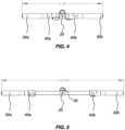
- Figure 4shows the exercise bar 10 in a first, retracted or shorter position.
- the first clamp assembly 40amay be positioned adjacent or immediately adjacent to a first side of the central hub 20, and the second clamp assembly 40b may be positioned adjacent or immediately adjacent to a second side of the central hub 20 (the second side of the central hub 20 being opposed to the first side).
- the inner tubes 24a, 24bmay be entirely or nearly entirely telescoped by the outer tubes 28a, 28b, respectively. That is, the first inner tube 24a may be telescoped inside the first outer tube 28a and the second inner tube 24b may be telescoped inside of the second outer tube 28b, respectively.
- This first, retracted or shorter positionmay be desirable for some exercises.
- a shorter exercise bar 10may be desired.
- Rowing barsmay typically be, for example, 53,34 cm (21 inches) wide, and this narrow bar tends to keep a user's arms straight out and parallel with each other as desired when rowing.
- the exercise bar 10 in this first, retracted or shorter positionmay be configured to have any length desired.
- the lengthmay be around 43 centimeters to around 63 centimeters. In other configurations the length may be around 48 centimeters to around 58 centimeters. Even more specifically, the length may be around 53 centimeters or 21" (inches). In other configurations, the length may be longer or shorter as desired.
- Figure 5shows the exercise bar 10 in a second, extended or longer position.
- the first clamp assembly 40amay be positioned away from a first side of the central hub 20, and the second clamp assembly 40b may be positioned away from a second side of the central hub 20 (the second side of the central hub 20 being opposed to the first side).
- the inner tubes 24a, 24bmay be extended outwardly from outer tubes 28a, 28b, respectively. That is, the first inner tube 24a may be telescoped so that a majority of the first inner tube 24a is outside of the first outer tube 28a. Similarly, the second inner tube 24b may be telescoped so that a majority of the second inner tube 24b is outside of the second outer tube 28b. This second, extended or longer position may be desirable for some exercises.
- the exercise bar 10 in this second, extended or longer positionmay be configured to have any length desired.
- the lengthmay be around 70 centimeters to 90 centimeters.
- the lengthmay be around 75 centimeters to 85 centimeters.
- the lengthmay be around 79 centimeters or around 31" (inches).
- the lengthmay be longer or shorter as desired for the second, extended or longer position.
- the exercise bar 10may be formed of any suitable type of materials.
- the inner tube 24 and/or outer tube 28may be formed of aluminum, which is durable and economical.
- the inner tube 24 and/or outer tube 28may be formed entirely or partially from carbon, which is a strong and lightweight material able to withstand the loads that are contemplated herein.
- Composites and other suitable materialsare also anticipated and contemplated herein.
- the exercise bar 10may be formed of materials and/or designed such that the exercise bar 10 may be able to float on the water or otherwise be buoyant. This may be convenient, for example, if the exercise bar 10 is dropped in the water when it is not tethered to any anchors.
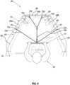
- Figure 6illustrates an exemplary inventive system 55 of a spa tub 15 or pool with a user 50 using the exercise bar 10 in a first, retracted position for rowing.
- the exemplary configuration of the inventive system 55 show in Figure 6generally includes a spa 15 and an exercise bar 10.
- the spa 15may be any shaped desired, and includes a spa shell 59 with one or more side walls 64 forming a container or space for receiving water.
- the side walls 64may have a top edge 68.
- a cover placed over a spa 15would typically rest on the top edge 68 of the side wall.
- One or more anchors 72 or connectorsare also placed on the top edge 68 and/or side walls 64 of the spa shell 59 as desired.
- the exercise bar 10may be placed at a predetermined vertical height.
- a combination of top edge 68 anchors and side wall 64 anchorsmay be used to achieve the desired vertical height of the exercise bar 10 in relation to the spa shell 59.
- the spa shell 59has a back (generally indicated at 74 in FIG. 6 ) where a user may sit, a front end 61, a first lateral side 63, and a second lateral side 65.
- the first lateral side 63is opposite the second lateral side 65.
- Anchors 72may be positioned at various locations as desired, including at various positions laterally and vertically.
- Anchors 72a, 72bmay be positioned on the top edge 68 of the spa shell 59.
- Anchors 72 along the top edge 68may provide for a higher connection compared to anchors provided in or on a spa side wall 64.
- anchors 72may also be provided along one or more spa side walls 64. These anchors may have a closer vertical placement to the water compared to anchors provided along the top edge 68 of the spa shell 59.
- anchors 72c, 72dmay be provided along a side wall 64 of the spa shell 59.
- anchors 72c, 72dmay be provided on a side wall 64 which is opposite the side wall where a user is sitting for rowing.
- the anchorsmay be provided on the side wall 64 which the user is facing while rowing.
- Anchors 72a, 72bmay be positioned on the top edge 68 of the spa shell 59.
- at least one anchor 72ais provided on a first top edge 68a
- at least one anchor 72bis provided on second top edge 68b, with first top edge 68a opposing second top edge 68b. This may provide anchors (72c, 72d) in front of the user and to the left (72a) and right (72b) of the user, to allow for a plurality of connection points to the exercise bar 10 to steady it and allow for a comfortable rowing experience.
- the exercise bar 10is attached to the anchors 72 via one or more resistance lines.
- resistance lines 75 of various resistance valuesmay be used as desired to provide different rowing experiences. Resistance lines of a higher resistance may be used when a more difficult or intense rowing experience. Resistance lines of a lower resistance may be used when a less difficult experience is desired, for example for users with a smaller muscle mass. Additionally, the number of resistance lines used may be varied depending on the exercise experience desired.
- Resistance lines of different resistance valuesmay also be placed at different positions with respect to the anchors 72 and the exercise bar 10. Any resistance lines known in the art may be used. For example, resistance lines may be formed of latex or synthetic rubber, etc., and may be formed in various lengths, widths, and shapes to provide varying resistance levels. A single resistance band may be used, two or more resistance bands may be used, etc. Additionally, resistance bands may be coupled together and/or to the anchors 72 and/or exercise bar 10.
- resistance bandsmay also be placed in a direction generally perpendicular to the movement of the rowing exercise. This may provide for resistance in additional directions.
- Resistance band 75amay be attached at a first end to the connector 30 of the central hub 20 of the exercise bar 10, and may be attached at a second end to the anchor 72a along the top edge 68a of the spa shell 59.
- resistance band 75bmay be attached at a first end to the connector 30 of the central hub 20 of the exercise bar 10, and may be attached at its second end to the anchor 72b along the top edge 68b of the spa shell 59. In other configurations, these perpendicular resistance bands may not be provided.
- an extension band 78 or resistance cableis connected to the connector 30 of the central hub 20.
- the extension band 78may have any resistance level desired.
- extension band 78may be a resistance cable, or it may be a rope or other connector that is not capable of being stretched like a resistance cable.
- a first end of the extension band 78may be connected to the connector 30 of the central hub, with a second end of the extension band 78 connected to two resistance bands (79a and 79b in Figure 6 ).
- each of the two resistance bandsmay connected at their first ends to the extension band 78 and at a second end to the anchors 72c and 72d, respectively.
- the extension band 78may connect directly to an anchor 72 provided in either a side wall 64 or top edge 68 of the spa shell 59.
- a usermay row within a swim spa in using a single, short exercise bar (when used to row, exercise bar may be referred to as a "row bar") tethered to a single line or resistance band that provides resistance when pulled.
- the row barmay be tethered at one or more positions within the spa to provide the resistance desired.
- the row barmay be tethered in directions perpendicular to the rowing movement.
- the row barmay be tether using various materials that vary in resistance and/or various lengths of tethers to provide the desired resistance. In other configurations, the length and/or material may not be varied, but rather users may merely pull harder or softer on the bar to achieve their desired level of resistance.
- the userwhen the user desires to do exercises that require an exercise bar 10 with a longer length, the user may telescope the inner tubes 24a, 24b with respect to the outer tubes 28a, 28b respectively. The user may then use the same exercise bar 10 to do exercises that require their hands to be placed farther apart.
Landscapes
- Health & Medical Sciences (AREA)
- Physical Education & Sports Medicine (AREA)
- General Health & Medical Sciences (AREA)
- Life Sciences & Earth Sciences (AREA)
- Biophysics (AREA)
- Orthopedic Medicine & Surgery (AREA)
- Vascular Medicine (AREA)
- Cardiology (AREA)
- Public Health (AREA)
- Epidemiology (AREA)
- Pain & Pain Management (AREA)
- Rehabilitation Therapy (AREA)
- Animal Behavior & Ethology (AREA)
- Veterinary Medicine (AREA)
- Rehabilitation Tools (AREA)
Description
- The present disclosure relates to a spa rowing system with the features of the preamble of claim 1 for developing or strengthening the muscles or joints of the body by working against a counterforce.
- Swim spas and pools offer good exercise for users through swimming; however, it can also be useful to provide other methods of resistance exercise in conjunction with a swim spa or pool. Known methods of "rowing" exercises in a swim spa or pool provide a user experience that simulates rowing a boat through water. That is, two separate oar-like bars are typically provided, each mounted to opposing walls and attached to resistance points. While this experience may simulate the experience of rowing a boat with two oars through water, it may not be similar to a user's experience with traditional rowing machines typically found in gyms.
- Additionally, it may be desirable to provide a plurality of resistance exercises that can be used with a single piece of exercise equipment in conjunction with a spa, such that the user does not have to purchase multiple pieces of exercise equipment to do multiple types of exercises. Patent publication
US 2003/100411 A1 already discloses a spa rowing system with the features of the preamble of claim 1. - The present invention is defined by the features of claim 1.
- The following drawings illustrate what are currently considered to be specific representative configurations for carrying out the invention and are not limiting as to embodiments which may be made in accordance with the present invention. The components in the drawings are not necessarily to scale relative to each other. Like reference numerals designate corresponding parts throughout the several views.
- The drawings are illustrative and not limiting of the scope of the invention which is defined by the appended claims. The various elements of the invention accomplish various aspects and objects of the invention. Not every element of the invention can be clearly displayed in a single drawing, and as such not every drawing shows each element of the invention.
FIG. 1 is a perspective view of an non-inventive embodiment of an exercise bar that may be used with a swim spa.FIG. 2 is an exploded view of the non-inventive embodiment of an exercise bar shown inFIG. 1 .FIG. 3 is a perspective view of an non-inventive embodiment of a connector that may be used with the exercise bar ofFIG. 1 .FIG. 4 is a front, plan view of an non-inventive embodiment of an exercise bar shown in a retracted position.FIG. 5 is a front, plan view of the non-inventive embodiment of an exercise bar shown inFIG. 3 shown in an extended position.FIG. 6 is a perspective view of an embodiment of an exercise bar in use for rowing in a swim spa according to the present invention.- The following provides a detailed description of particular embodiments of the present invention. Reference will now be made to the drawings in which the various elements of the illustrated configurations will be given numerical designations and in which the invention will be discussed to enable one skilled in the art to make and use the invention. It is to be understood that the following description is only exemplary of the principles of the present invention, and should not be viewed as narrowing the scope of the claims which follow, which claims define the full scope of the invention.
- It will be appreciated that various aspects discussed in one drawing may be present and/or used in conjunction with the embodiment shown in another drawing, and each element shown in multiple drawings may be discussed only once. For example, in some cases, detailed description of well-known items or repeated description of substantially the same configurations may be omitted. This facilitates the understanding of those skilled in the art by avoiding an unnecessarily redundant description. The accompanying drawings and the following description are provided in order for those skilled in the art to fully understand the present disclosure, and these are not intended to limit the scope of claims.
- Reference in the specification to "one configuration" "one embodiment," "a configuration" or "an embodiment" means that a particular feature, structure, or characteristic described in connection with the configuration is included in at least one configuration, but is not a requirement that such feature, structure or characteristic be present in any particular configuration unless expressly set forth in the claims as being present. The appearances of the phrase "in one configuration" in various places may not necessarily limit the inclusion of a particular element of the invention to a single configuration, rather the element may be included in other or all configurations discussed herein.
- Furthermore, the described features, structures, or characteristics of configurations of the invention may be combined in any suitable manner in one or more configurations. In the following description, numerous specific details are provided, such as examples of products or manufacturing techniques that may be used, to provide a thorough understanding of configurations of the invention. One skilled in the relevant art will recognize, however, that configurations of the invention may be practiced without one or more of the specific details, or with other methods, components, materials, and so forth. In other instances, well-known structures, materials, or operations are not shown or described in detail to avoid obscuring aspects of the invention.
- As used in this specification and the appended claims, singular forms such as "a," "an," and "the" may include the plural unless the context clearly dictates otherwise. Thus, for example, reference to "an anchor" may include one or more of such anchors, and reference to "the coupling member" may include reference to one or more of such coupling members.
- As used herein, the term "generally" refers to something that is more of the designated adjective than not, or the converse if used in the negative. As used herein, the term "about" is used to provide flexibility to a numerical range endpoint by providing that a given value may be "a little above" or "a little below" the endpoint while still accomplishing the function associated with the range, for example, "about" may be within 10% of the given number or given range. As used herein, a plurality of items, structural elements, compositional elements, and/or materials may be presented in a common list for convenience. However, these lists should be construed as though each member of the list is individually identified as a separate and unique member.
- Numerical data may be expressed or presented herein in a range format. It is to be understood that such a range format is used merely for convenience and brevity and thus should be interpreted flexibly to include not only the numerical values explicitly recited as the limits of the range, but also to include all the individual numerical values or sub-ranges encompassed within that range as if each numerical value and sub-range is explicitly recited. As an illustration, a numerical range of "about 5 to about 60" should be interpreted to include not only the explicitly recited values of about 1 to about 5, but also include individual values and sub-ranges within the indicated range. Thus, included in this numerical range are individual values such as 6, 7, 8, 9, etc., through 60, and sub-ranges such as from 10-20, from 30-40, and from 50-60, etc., as well as each number individually. This same principle applies to ranges reciting only one numerical value as a minimum or a maximum. Furthermore, such an interpretation should apply regardless of the breadth of the range or the characteristics being described. Additionally, the word "connected" and "coupled" is used throughout for clarity of the description and can include either a direct connection or an indirect connection.
- The present disclosure relates generally to a system for providing an exercise bar for use in conjunction with a spa, swim spa, pool, etc. As used herein, "spa" or "swim spa" refers to a hot tub, swim spa, and/or a jetted tub, whether in ground or aboveground. It will be appreciated that while the exercise bar described herein is described in reference to a spa, it may be similarly used in conjunction with a pool or other swimming system. Similarly, "spa shell" refers to the outer shell or structure of the spa, and encompasses the outer structure of a spa or any other swimming vessel, such as the outer structure of a pool, etc. Thus, "spa shell" means both the shell of a spa and the deck of a pool.
- As used herein, "spa," "spa tub," and "heated spa," may be used to refer to a heated or unheated pool or spa, including the shell of a spa, the shell of the spa with a cabinet, an in-ground spa, or an aboveground spa. As used herein, "length" and "width" may be interchangeable. For example, an exercise bar may have a specific length of 53,34 cm (21 inches) but because a user grips the bar on either end, this length may also be referred to as the width of the exercise bar because it provides a specific width apart for the user's hands.
FIGs. 1-2 show an exemplary configuration of an non-inventive embodiment of anexercise bar 10. The exercise bar may be used in conjunction with any number of exercises either within the water of thespa 15, or outside the water and proximal to the spa. Theexercise bar 10 may be adjusted, as described below, so that it may be used for exercises typically done with standard cable machines, whether the exercises require a shorter bar or a longer bar, and whether the user desires to do the exercises with the added resistance in the water of the spa, or outside the water adjacent to thespa 15. Without limitation, theexercise bar 10 may be used for rowing, barbell curls, single arm curls, double arm curls, lateral raises, Egyptian raises, tricep rope pushdowns, single arm tricep pulldowns, single arm shoulder press, double arm shoulder press, standing lifts, rear delt rows, squats, hamstring extensions, calf raises, hip adduction, hip abduction, lateral pulls, lateral pushdowns, tricep extensions, chest press, shoulder press, crossovers, etc. All these exercises may be done with asingle exercise bar 10, by adjusting the length of theexercise bar 10 and without the need to change the exercise bar for another exercise bar of a different length.- The configuration of the
exercise bar 10 shown inFIGs. 1-2 may include acentral hub 20, an inner tube 24 on each side of thecentral hub 20, and an outer tube 28 on each side of the central hub 20 (for example,inner tube 24a on a first side of thecentral hub 20 andinner tube 24b on a second side of thecentral hub 20 and similarlyouter tube 28a on a first side of thecentral hub 20 andouter tube 28b on a second side of the central hub 20). The inner tube 24 and the outer tube 28 may be configured to telescope, as described in more detail below, so that theexercise bar 10 may be adjusted to two or more lengths. In other configurations, the exercise bar may be adjusted through other means, as described in more detail below. - The
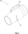
central hub 20 may include aconnector 30 attached to the central hub. Theconnector 30 may be pivotably connected to thecentral hub 20, or may be attached in a single fixed position. Theconnector 30 may allow the exercise bar to be attached via one or more resistance cables to one or more anchors in the spa shell, as described in more detail below. A pivotable connector may allow theexercise bar 10 to rotate or swivel with respect to the resistance cables attached thereto, while a fixedly attached connector may not allow theexercise bar 10 to rotate with respect to resistance cables attached thereto. Depending on the desired exercise experience, a pivotable connector or a fixed connector may be provided. - In some configurations, one or more of the
outer tubes exercise bar 10. For example, theexercise bar 10 may be provided with afirst handle 32a or handgrip to be gripped by a user's left hand and/or asecond handle 32b or handgrip to be gripped by a user's right hand. In configurations with hollowouter tubes exercise bar 10 to float on the water, which may be more convenient for use. Similarly, each of theinner tubes central hub 20 may be provided with aninner tube cap - The
exercise bar 10 may also include an attachment mechanism to attach the inner tube 24 to the outer tube 28. Aclamp assembly 40 may attach the inner tube 24 to the outer tube 28. For example, afirst clamp assembly 40a may be provided to attach firstinner tube 24a to firstouter tube 28a. Similarly, asecond clamp assembly 40b may be provided to attach secondinner tube 24b to secondouter tube 28b. Thesecond clamp assembly 40b may be on an opposing side of thecentral hub 20 from thefirst clamp assembly 40a. As seen inFigure 3 , theclamp assembly 40 may be a telescoping clamp assembly and may include a cut-awaygroove 45 or channel to allow flexibility in theclamp assembly 40 and generate a suitable amount of friction for both the clamped and released states. Forclamp assemblies 40 that twist to lock and unlock, aprojection 48 or tab may be provided to assist a user in twisting the clamp assembly into the locked or unlocked position. In other configurations, a projection may not be provided. Theclamp assembly 40 may also include one or more screws or other attachment means, for example, on or more aprojection 48, to provide a suitable amount of compression force on theclamp assembly 40. - Any suitable type of locking mechanism can be used to lock the inner tube 24 relative to the outer tube 28 and thus adjust the length of the exercise bar. For example, an external lever lock may be used, such as a flip lever clamp. An external lever-lock is a lever-based, clamp-like mechanism that allows for easy locking and unlocking of locking mechanism to adjust the length of the
exercise bar 10. Other types of clamps, such as clamshell and cam lock clamps, may also be used. In other configurations, a twist lock may be used. Or a combination of twist locks, external lever locks, etc. may be used to achieve a balance between the strength, weight, and ease of use for theexercise bar 10. One or more compression rings may also be provided to provide additional compression for telescoping as needed. - In other configurations, the
exercise bar 10 may be machined with a plurality of holes in one of the outer tube 28 and/or inner tube 24, and provided with quick release ball lock pins to connect the inner tube 24 and outer tube 28 together at various discrete lengths. In other configurations, one or more of the inner tube 24 and/or outer tube 28 may be machined with a plurality of holes and the other of the inner tube 24 and/or outer tube 28 may be provided with button clips to adjust the length of theexercise bar 10. Other types of connection means to secure the inner tube 24 to the outer tube 28 at variable lengths may also be used. - Exercise bars are typically designed with different widths or lengths to concentrate the user's movement towards specific muscle groups. For example, rowing bars may typically be narrower because a narrow bar (with a shorter length) tends to keep a user's arms straight out and parallel with each other as desired when rowing. Other exercises like pulldowns usually use a wider bar. Using telescoping techniques, both widths may be achieved in a
single exercise bar 10. Figure 4 shows theexercise bar 10 in a first, retracted or shorter position. Thefirst clamp assembly 40a may be positioned adjacent or immediately adjacent to a first side of thecentral hub 20, and thesecond clamp assembly 40b may be positioned adjacent or immediately adjacent to a second side of the central hub 20 (the second side of thecentral hub 20 being opposed to the first side). Theinner tubes outer tubes inner tube 24a may be telescoped inside the firstouter tube 28a and the secondinner tube 24b may be telescoped inside of the secondouter tube 28b, respectively.- This first, retracted or shorter position may be desirable for some exercises. For example, for providing a rowing experience within the spa, a
shorter exercise bar 10 may be desired. Rowing bars may typically be, for example, 53,34 cm (21 inches) wide, and this narrow bar tends to keep a user's arms straight out and parallel with each other as desired when rowing. Theexercise bar 10 in this first, retracted or shorter position may be configured to have any length desired. For example, in the exemplary configuration shown inFigure 4 , the length may be around 43 centimeters to around 63 centimeters. In other configurations the length may be around 48 centimeters to around 58 centimeters. Even more specifically, the length may be around 53 centimeters or 21" (inches). In other configurations, the length may be longer or shorter as desired. Figure 5 shows theexercise bar 10 in a second, extended or longer position. Thefirst clamp assembly 40a may be positioned away from a first side of thecentral hub 20, and thesecond clamp assembly 40b may be positioned away from a second side of the central hub 20 (the second side of thecentral hub 20 being opposed to the first side). Theinner tubes outer tubes inner tube 24a may be telescoped so that a majority of the firstinner tube 24a is outside of the firstouter tube 28a. Similarly, the secondinner tube 24b may be telescoped so that a majority of the secondinner tube 24b is outside of the secondouter tube 28b. This second, extended or longer position may be desirable for some exercises. For example, when using the exercise bar for exercises such as bench press and pulldown simulations, a longer orwider exercise bar 10 may be desired. Theexercise bar 10 in this second, extended or longer position may be configured to have any length desired. For example, in the exemplary configuration shown inFigure 5 , the length may be around 70 centimeters to 90 centimeters. In other configurations, the length may be around 75 centimeters to 85 centimeters. Even more particularly, the length may be around 79 centimeters or around 31" (inches). In other configurations, the length may be longer or shorter as desired for the second, extended or longer position.- The
exercise bar 10 may be formed of any suitable type of materials. For example, the inner tube 24 and/or outer tube 28 may be formed of aluminum, which is durable and economical. In other configurations, the inner tube 24 and/or outer tube 28 may be formed entirely or partially from carbon, which is a strong and lightweight material able to withstand the loads that are contemplated herein. Composites and other suitable materials are also anticipated and contemplated herein. In some configurations, theexercise bar 10 may be formed of materials and/or designed such that theexercise bar 10 may be able to float on the water or otherwise be buoyant. This may be convenient, for example, if theexercise bar 10 is dropped in the water when it is not tethered to any anchors. Figure 6 illustrates an exemplaryinventive system 55 of aspa tub 15 or pool with auser 50 using theexercise bar 10 in a first, retracted position for rowing. The exemplary configuration of theinventive system 55 show inFigure 6 generally includes aspa 15 and anexercise bar 10. Thespa 15 may be any shaped desired, and includes aspa shell 59 with one ormore side walls 64 forming a container or space for receiving water. Theside walls 64 may have atop edge 68. A cover placed over aspa 15 would typically rest on thetop edge 68 of the side wall. One or more anchors 72 or connectors are also placed on thetop edge 68 and/orside walls 64 of thespa shell 59 as desired. By connecting the anchors to thetop edge 68 and/orside walls 64 of thespa shell 59, theexercise bar 10 may be placed at a predetermined vertical height. For example, a combination oftop edge 68 anchors andside wall 64 anchors may be used to achieve the desired vertical height of theexercise bar 10 in relation to thespa shell 59. Thespa shell 59 has a back (generally indicated at 74 inFIG. 6 ) where a user may sit, a front end 61, a firstlateral side 63, and a secondlateral side 65. The firstlateral side 63 is opposite the secondlateral side 65.- In some configurations, it may be desirable to provide one or more anchors 72 on the
spa shell 59. Anchors 72 may be positioned at various locations as desired, including at various positions laterally and vertically. For example, anchors 72a, 72b may be positioned on thetop edge 68 of thespa shell 59. Anchors 72 along thetop edge 68 may provide for a higher connection compared to anchors provided in or on aspa side wall 64. In addition to, or instead of, anchors 72 along thetop edge 68 of thespa shell 59, anchors 72 may also be provided along one or morespa side walls 64. These anchors may have a closer vertical placement to the water compared to anchors provided along thetop edge 68 of thespa shell 59. Depending on the height of the connection desired for the particular exercise, it may be desirable to have a plurality of anchors provided at various locations on the spa shell to allow for many different positions possible for connecting theexercise bar 10 for various exercise options. - In one exemplary configuration for a rowing exercise, anchors 72c, 72d may be provided along a
side wall 64 of thespa shell 59. For example, anchors 72c, 72d may be provided on aside wall 64 which is opposite the side wall where a user is sitting for rowing. In other words, the anchors may be provided on theside wall 64 which the user is facing while rowing.Anchors top edge 68 of thespa shell 59. In the exemplary configuration shown inFigure 6 , at least oneanchor 72a is provided on a firsttop edge 68a, and at least oneanchor 72b is provided on secondtop edge 68b, with firsttop edge 68a opposing secondtop edge 68b. This may provide anchors (72c, 72d) in front of the user and to the left (72a) and right (72b) of the user, to allow for a plurality of connection points to theexercise bar 10 to steady it and allow for a comfortable rowing experience. - In the exemplary configuration of
Figure 6 , theexercise bar 10 is attached to the anchors 72 via one or more resistance lines. For example, resistance lines 75 of various resistance values may be used as desired to provide different rowing experiences. Resistance lines of a higher resistance may be used when a more difficult or intense rowing experience. Resistance lines of a lower resistance may be used when a less difficult experience is desired, for example for users with a smaller muscle mass. Additionally, the number of resistance lines used may be varied depending on the exercise experience desired. - Resistance lines of different resistance values may also be placed at different positions with respect to the anchors 72 and the
exercise bar 10. Any resistance lines known in the art may be used. For example, resistance lines may be formed of latex or synthetic rubber, etc., and may be formed in various lengths, widths, and shapes to provide varying resistance levels. A single resistance band may be used, two or more resistance bands may be used, etc. Additionally, resistance bands may be coupled together and/or to the anchors 72 and/orexercise bar 10. As seen in the exemplary configuration ofFigure 6 , in addition to resistance bands being provided parallel or in line with the general direction of movement of the rowing exercise (i.e., from the first end side wall 64c to the back of the spa generally indicated at 74), if desired, resistance bands may also be placed in a direction generally perpendicular to the movement of the rowing exercise. This may provide for resistance in additional directions.Resistance band 75a may be attached at a first end to theconnector 30 of thecentral hub 20 of theexercise bar 10, and may be attached at a second end to theanchor 72a along thetop edge 68a of thespa shell 59. Similarly,resistance band 75b may be attached at a first end to theconnector 30 of thecentral hub 20 of theexercise bar 10, and may be attached at its second end to theanchor 72b along thetop edge 68b of thespa shell 59. In other configurations, these perpendicular resistance bands may not be provided. - In the exemplary configuration of
Figure 6 , anextension band 78 or resistance cable is connected to theconnector 30 of thecentral hub 20. Theextension band 78 may have any resistance level desired. For example,extension band 78 may be a resistance cable, or it may be a rope or other connector that is not capable of being stretched like a resistance cable. A first end of theextension band 78 may be connected to theconnector 30 of the central hub, with a second end of theextension band 78 connected to two resistance bands (79a and 79b inFigure 6 ). In turn, each of the two resistance bands may connected at their first ends to theextension band 78 and at a second end to theanchors extension band 78 may connect directly to an anchor 72 provided in either aside wall 64 ortop edge 68 of thespa shell 59. - According to an exemplary method as disclosed herein, a user may row within a swim spa in using a single, short exercise bar (when used to row, exercise bar may be referred to as a "row bar") tethered to a single line or resistance band that provides resistance when pulled. The row bar may be tethered at one or more positions within the spa to provide the resistance desired. For example, the row bar may be tethered in directions perpendicular to the rowing movement. Similarly, the row bar may be tether using various materials that vary in resistance and/or various lengths of tethers to provide the desired resistance. In other configurations, the length and/or material may not be varied, but rather users may merely pull harder or softer on the bar to achieve their desired level of resistance.
- According to another method, when the user desires to do exercises that require an
exercise bar 10 with a longer length, the user may telescope theinner tubes outer tubes same exercise bar 10 to do exercises that require their hands to be placed farther apart. - Although the foregoing disclosure provides many specifics, such as use of the system in spas, it will be appreciated that pools, and other water holding devices are contemplated and these should not be construed as limiting the scope of any of the ensuing claims. Other embodiments and configurations may be devised which do not depart from the scopes of the claims. Features from different embodiments and configurations may be employed separately or in combination. Accordingly, all additions, deletions and modifications to the disclosed subject matter that fall within the scopes of the claims are to be embraced thereby.
Claims (10)
- A spa rowing system (55) comprising:a spa shell (59) comprising an anchor (72c) on a front end (61) of the spa shell (59), an anchor (72a) on a first lateral side (63) of the spa shell (59), and an anchor (72b) on a second lateral side (65) of the spa shell (59), the first lateral side (63) opposing the second lateral side (65) of the spa shell (59);an exercise bar (10) with a first handle (32a) and a second handle (32b), the first handle (32a) to be gripped by a user's first hand and the second handle (32b) to be gripped by a user's second hand;a connector (30) mounted to the exercise bar (10);a first resistance cable (75c) having a first end connectable to the connector (30) of the exercise bar (10) and a second end connectable to the anchor (72c) on the first end of the spa shell (59), to enable the exercise bar (10) to be pulled away from the first end of the spa shell (59) under resistance of the first resistance cable;characterized in that the exercise bar (10) is adjustable between a first length and a second length, whereby the first length is shorter than the second length,and an extension band (78), the extension band (78) having a first end connectable to the connector of the exercise bar (10) and a second end connectable to one or more resistance cables.
- The spa rowing system (55) of claim 1, further comprising:a second resistance cable (75a) having a first end connectable to the connector (30) of the exercise bar and a second end connectable to the anchor (72a) on the first lateral side of the spa shell (59); anda third resistance cable (75b) having a first end connectable to the connector (30) of the exercise bar (10) and a second end connectable to the anchor (72b) on the second lateral side of the spa shell (59), the second resistance cable (75a) and third resistance cable (75b) to provide resistance in a generally perpendicular direction to the resistance of the first resistance cable (78).
- The spa rowing system (55) of claim 1 or claim 2, wherein the spa shell (59) comprises a top edge (68) and a side wall (64), and wherein the anchor on the first end of the spa shell (59) is on a side wall, and wherein the anchor on the first lateral side of the spa shell (59) is on the top edge, and wherein the anchor on the second lateral side of the spa shell (59) is on the top edge, the anchor (72c) on the first end of the spa shell (59) being located vertically below the anchor (72a) on the first lateral side (63) and the anchor (72b) on the second lateral side (65), to enable connection of the exercise bar (10) at a predetermined height.
- The spa rowing system (55) of any one of claims 1-3, wherein the second end of the extension band (78) is connected to the first end of the first resistance cable (75c).
- The spa rowing system (55) of any one of claims 1-4, wherein the system (55) further comprises a fourth resistance cable (75d) and a wherein the anchor on the first end of the spa shell (59) comprises a first anchor (72c) and a second anchor (72d), the fourth resistance cable (75d) having a first end connected to the second end of the extension band (78) and a second end connected to the second anchor (72d) on the first end of the spa shell (59).
- The spa rowing system (55) of claim 4, wherein the first anchor (72c) and the second anchor (72d) on the first end (65) of the spa are located on a side wall (64a) of the spa shell (59).
- The spa rowing system (55) of any one of claims 1 through 6, wherein the exercise bar (10) comprises:a central hub (20);a first inner tube (24a) attached to a first side of the central hub (20) and a first outer tube (28a) in telescoping connection with the first inner tube (24a) , the first handle (32a) in connection with the first outer tube (28a);a second inner tube (24b) attached to a second side of the central hub (20), the second side of the central hub (20) being opposed to the first side of the central hub (20), and a second outer tube (28b) in telescoping connection with the second inner tube (28a), the second handle (32b) in connection with the second outer tube (28b); and the connector (30) mounted to the central hub (20).
- The spa rowing system (55) of claim 7, wherein the connector (30) mounted to the central hub (20) of the exercise bar (10) is a pivotable connector.
- The spa rowing system (55) of any one of claims 1 through 8, wherein the exercise bar (10) is continuously adjustable.
- The spa rowing system of any one of claims 1 through 9 , wherein the exercise bar (10) is adjustable between a first, shorter length and a second, longer length.
Applications Claiming Priority (1)
| Application Number | Priority Date | Filing Date | Title |
|---|---|---|---|
| US17/467,106US12064661B2 (en) | 2021-09-03 | 2021-09-03 | Adjustable exercise bar device for spa and methods of use |
Publications (2)
| Publication Number | Publication Date |
|---|---|
| EP4144423A1 EP4144423A1 (en) | 2023-03-08 |
| EP4144423B1true EP4144423B1 (en) | 2024-08-14 |
Family
ID=83191905
Family Applications (1)
| Application Number | Title | Priority Date | Filing Date |
|---|---|---|---|
| EP22193753.5AActiveEP4144423B1 (en) | 2021-09-03 | 2022-09-02 | Adjustable exercise bar device for spa and methods of use |
Country Status (4)
| Country | Link |
|---|---|
| US (1) | US12064661B2 (en) |
| EP (1) | EP4144423B1 (en) |
| AU (1) | AU2022224852B2 (en) |
| CA (1) | CA3171193A1 (en) |
Families Citing this family (4)
| Publication number | Priority date | Publication date | Assignee | Title |
|---|---|---|---|---|
| WO2021262818A1 (en)* | 2020-06-24 | 2021-12-30 | Djm Consulting Llc | Feathering handle for rowing machine |
| USD1028135S1 (en)* | 2022-04-12 | 2024-05-21 | Vladymir Senatus | Flat grip tricep bar |
| USD1082978S1 (en)* | 2023-06-09 | 2025-07-08 | Zhuzhou Changzhou E-Commerce Co., Ltd. | Straight bar cable attachment |
| USD1026137S1 (en)* | 2023-09-07 | 2024-05-07 | Jinghua Li | Pilates bar |
Family Cites Families (21)
| Publication number | Priority date | Publication date | Assignee | Title |
|---|---|---|---|---|
| US3471145A (en)* | 1967-04-11 | 1969-10-07 | Thoylo Corp | Exerciser with pneumatic resistance element |
| US5106078A (en)* | 1990-02-26 | 1992-04-21 | Rowe Victor L | Water Exerciser |
| US5571064A (en)* | 1995-05-26 | 1996-11-05 | Holm; James E. | Elastic exercise device with segmented handle |
| US5554091A (en)* | 1995-06-01 | 1996-09-10 | Patey; Kenneth | Method and apparatus for minimizing lacticemia during exercise |
| US7597652B2 (en)* | 2001-11-28 | 2009-10-06 | Dimension One Spas | Hydrotherapy mounting apparatus and exercise system |
| US20040185990A1 (en)* | 2003-03-17 | 2004-09-23 | Rob Orescan | Portable exercise apparatus and method |
| US7086999B2 (en)* | 2003-10-22 | 2006-08-08 | Jeff Jeneve | Bar with sliding handgrips for resistance exercise device |
| EP1719489A1 (en)* | 2005-05-04 | 2006-11-08 | Stefano Tomatis | Station for gymnastics in water |
| US7326157B2 (en)* | 2006-01-24 | 2008-02-05 | Ying-Ching Wu | Exercise device with stretchable elastic member |
| US7591763B1 (en)* | 2008-03-07 | 2009-09-22 | Gymflex Fitness, Llc | Portable convertible multifunction exercise apparatus and method |
| US8721507B2 (en)* | 2010-04-13 | 2014-05-13 | Vaughan Martin Blancher | Multi-planar resistance band exercise system |
| US20110271436A1 (en)* | 2010-05-10 | 2011-11-10 | Michael Kite | Exercise and swim spa |
| US8678983B1 (en)* | 2010-11-18 | 2014-03-25 | Chad Brown | Strap based resistance exercise device |
| US20140295983A1 (en)* | 2013-03-15 | 2014-10-02 | Butler Nooner | Exercise, training, and therapy tool and related systems and methods |
| US20160047405A1 (en)* | 2014-08-14 | 2016-02-18 | Kevin Curley | Collapsible Exercise Bar |
| US10806960B2 (en)* | 2016-07-29 | 2020-10-20 | Joseph Sanseverino | Exercise device |
| US10220248B1 (en)* | 2018-07-24 | 2019-03-05 | Super Swim Corp. | Spa rowing adapter |
| US11213712B1 (en)* | 2019-03-20 | 2022-01-04 | Brian S. Lejuez | Multi-function exercise device |
| US11148001B2 (en) | 2019-07-25 | 2021-10-19 | William J. Nurge | Exercise system |
| US11324992B2 (en)* | 2019-11-22 | 2022-05-10 | Blake Kassel | Exercise bar |
| US20210154521A1 (en)* | 2019-11-22 | 2021-05-27 | Mr. Blake Kassel | Exercise bar |
- 2021
- 2021-09-03USUS17/467,106patent/US12064661B2/enactiveActive
- 2022
- 2022-08-24CACA3171193Apatent/CA3171193A1/enactivePending
- 2022-09-02EPEP22193753.5Apatent/EP4144423B1/enactiveActive
- 2022-09-02AUAU2022224852Apatent/AU2022224852B2/enactiveActive
Also Published As
| Publication number | Publication date |
|---|---|
| AU2022224852A1 (en) | 2023-03-23 |
| US20230073056A1 (en) | 2023-03-09 |
| US12064661B2 (en) | 2024-08-20 |
| CA3171193A1 (en) | 2023-03-03 |
| EP4144423A1 (en) | 2023-03-08 |
| AU2022224852B2 (en) | 2024-05-16 |
Similar Documents
| Publication | Publication Date | Title |
|---|---|---|
| EP4144423B1 (en) | Adjustable exercise bar device for spa and methods of use | |
| US7611450B2 (en) | Portable, collapsible exercise machine | |
| EP1276543B1 (en) | Exercise apparatus | |
| CA1218392A (en) | Physical exercise apparatus | |
| US6712740B2 (en) | Exercise apparatus | |
| US7766804B2 (en) | Abdominal exerciser and method | |
| US4585229A (en) | Exercising apparatus | |
| US20060052223A1 (en) | Personal exercise system | |
| US20030017918A1 (en) | Multi-functional weight training machine with horizontal and vertical axes of rotation | |
| US11426621B2 (en) | Exercise apparatuses | |
| US20130324376A1 (en) | Resistance training apparatus | |
| US11439859B2 (en) | Multifunctional fitness horizontal bar | |
| WO2023163728A1 (en) | Exercise machine system and method of use | |
| US11918844B2 (en) | Exercise backpack and methods of use | |
| US4429870A (en) | Physical exercising apparatus | |
| US6126581A (en) | Exercise equipment for sit-ups | |
| KR102115695B1 (en) | weight machine | |
| US5180161A (en) | Exercise machine | |
| US12303739B1 (en) | Exercise machine system and method of use | |
| US5779606A (en) | Multi-function exerciser | |
| CN219001859U (en) | Arm of force for bird power station | |
| US20180290011A1 (en) | Variable grip triceps attachment | |
| US20180250545A1 (en) | Versa-Band | |
| WO2008082727A2 (en) | Portable exercise device | |
| GB2507591A (en) | Pulley bar for weight stack comprising resilient hinge |
Legal Events
| Date | Code | Title | Description |
|---|---|---|---|
| PUAI | Public reference made under article 153(3) epc to a published international application that has entered the european phase | Free format text:ORIGINAL CODE: 0009012 | |
| STAA | Information on the status of an ep patent application or granted ep patent | Free format text:STATUS: THE APPLICATION HAS BEEN PUBLISHED | |
| AK | Designated contracting states | Kind code of ref document:A1 Designated state(s):AL AT BE BG CH CY CZ DE DK EE ES FI FR GB GR HR HU IE IS IT LI LT LU LV MC MK MT NL NO PL PT RO RS SE SI SK SM TR | |
| STAA | Information on the status of an ep patent application or granted ep patent | Free format text:STATUS: REQUEST FOR EXAMINATION WAS MADE | |
| REG | Reference to a national code | Ref country code:HK Ref legal event code:DE Ref document number:40087927 Country of ref document:HK | |
| 17P | Request for examination filed | Effective date:20230908 | |
| RBV | Designated contracting states (corrected) | Designated state(s):AL AT BE BG CH CY CZ DE DK EE ES FI FR GB GR HR HU IE IS IT LI LT LU LV MC MK MT NL NO PL PT RO RS SE SI SK SM TR | |
| GRAP | Despatch of communication of intention to grant a patent | Free format text:ORIGINAL CODE: EPIDOSNIGR1 | |
| STAA | Information on the status of an ep patent application or granted ep patent | Free format text:STATUS: GRANT OF PATENT IS INTENDED | |
| RIC1 | Information provided on ipc code assigned before grant | Ipc:A61H 33/00 20060101ALI20240212BHEP Ipc:A63B 71/02 20060101ALI20240212BHEP Ipc:A63B 22/00 20060101ALI20240212BHEP Ipc:A63B 69/06 20060101ALI20240212BHEP Ipc:A63B 21/055 20060101ALI20240212BHEP Ipc:A63B 69/08 20060101AFI20240212BHEP | |
| INTG | Intention to grant announced | Effective date:20240306 | |
| GRAS | Grant fee paid | Free format text:ORIGINAL CODE: EPIDOSNIGR3 | |
| GRAA | (expected) grant | Free format text:ORIGINAL CODE: 0009210 | |
| STAA | Information on the status of an ep patent application or granted ep patent | Free format text:STATUS: THE PATENT HAS BEEN GRANTED | |
| AK | Designated contracting states | Kind code of ref document:B1 Designated state(s):AL AT BE BG CH CY CZ DE DK EE ES FI FR GB GR HR HU IE IS IT LI LT LU LV MC MK MT NL NO PL PT RO RS SE SI SK SM TR | |
| REG | Reference to a national code | Ref country code:GB Ref legal event code:FG4D | |
| REG | Reference to a national code | Ref country code:CH Ref legal event code:EP | |
| REG | Reference to a national code | Ref country code:DE Ref legal event code:R096 Ref document number:602022005301 Country of ref document:DE | |
| REG | Reference to a national code | Ref country code:IE Ref legal event code:FG4D | |
| PGFP | Annual fee paid to national office [announced via postgrant information from national office to epo] | Ref country code:DE Payment date:20240926 Year of fee payment:3 | |
| REG | Reference to a national code | Ref country code:LT Ref legal event code:MG9D | |
| REG | Reference to a national code | Ref country code:NL Ref legal event code:MP Effective date:20240814 | |
| PG25 | Lapsed in a contracting state [announced via postgrant information from national office to epo] | Ref country code:NO Free format text:LAPSE BECAUSE OF FAILURE TO SUBMIT A TRANSLATION OF THE DESCRIPTION OR TO PAY THE FEE WITHIN THE PRESCRIBED TIME-LIMIT Effective date:20241114 | |
| REG | Reference to a national code | Ref country code:AT Ref legal event code:MK05 Ref document number:1712753 Country of ref document:AT Kind code of ref document:T Effective date:20240814 | |
| PG25 | Lapsed in a contracting state [announced via postgrant information from national office to epo] | Ref country code:GR Free format text:LAPSE BECAUSE OF FAILURE TO SUBMIT A TRANSLATION OF THE DESCRIPTION OR TO PAY THE FEE WITHIN THE PRESCRIBED TIME-LIMIT Effective date:20241115 Ref country code:NL Free format text:LAPSE BECAUSE OF FAILURE TO SUBMIT A TRANSLATION OF THE DESCRIPTION OR TO PAY THE FEE WITHIN THE PRESCRIBED TIME-LIMIT Effective date:20240814 Ref country code:PL Free format text:LAPSE BECAUSE OF FAILURE TO SUBMIT A TRANSLATION OF THE DESCRIPTION OR TO PAY THE FEE WITHIN THE PRESCRIBED TIME-LIMIT Effective date:20240814 Ref country code:FI Free format text:LAPSE BECAUSE OF FAILURE TO SUBMIT A TRANSLATION OF THE DESCRIPTION OR TO PAY THE FEE WITHIN THE PRESCRIBED TIME-LIMIT Effective date:20240814 Ref country code:PT Free format text:LAPSE BECAUSE OF FAILURE TO SUBMIT A TRANSLATION OF THE DESCRIPTION OR TO PAY THE FEE WITHIN THE PRESCRIBED TIME-LIMIT Effective date:20241216 | |
| PG25 | Lapsed in a contracting state [announced via postgrant information from national office to epo] | Ref country code:BG Free format text:LAPSE BECAUSE OF FAILURE TO SUBMIT A TRANSLATION OF THE DESCRIPTION OR TO PAY THE FEE WITHIN THE PRESCRIBED TIME-LIMIT Effective date:20240814 | |
| PG25 | Lapsed in a contracting state [announced via postgrant information from national office to epo] | Ref country code:LV Free format text:LAPSE BECAUSE OF FAILURE TO SUBMIT A TRANSLATION OF THE DESCRIPTION OR TO PAY THE FEE WITHIN THE PRESCRIBED TIME-LIMIT Effective date:20240814 | |
| PG25 | Lapsed in a contracting state [announced via postgrant information from national office to epo] | Ref country code:IS Free format text:LAPSE BECAUSE OF FAILURE TO SUBMIT A TRANSLATION OF THE DESCRIPTION OR TO PAY THE FEE WITHIN THE PRESCRIBED TIME-LIMIT Effective date:20241214 Ref country code:AT Free format text:LAPSE BECAUSE OF FAILURE TO SUBMIT A TRANSLATION OF THE DESCRIPTION OR TO PAY THE FEE WITHIN THE PRESCRIBED TIME-LIMIT Effective date:20240814 | |
| PG25 | Lapsed in a contracting state [announced via postgrant information from national office to epo] | Ref country code:HR Free format text:LAPSE BECAUSE OF FAILURE TO SUBMIT A TRANSLATION OF THE DESCRIPTION OR TO PAY THE FEE WITHIN THE PRESCRIBED TIME-LIMIT Effective date:20240814 | |
| PG25 | Lapsed in a contracting state [announced via postgrant information from national office to epo] | Ref country code:RS Free format text:LAPSE BECAUSE OF FAILURE TO SUBMIT A TRANSLATION OF THE DESCRIPTION OR TO PAY THE FEE WITHIN THE PRESCRIBED TIME-LIMIT Effective date:20241114 Ref country code:ES Free format text:LAPSE BECAUSE OF FAILURE TO SUBMIT A TRANSLATION OF THE DESCRIPTION OR TO PAY THE FEE WITHIN THE PRESCRIBED TIME-LIMIT Effective date:20240814 | |
| PG25 | Lapsed in a contracting state [announced via postgrant information from national office to epo] | Ref country code:RS Free format text:LAPSE BECAUSE OF FAILURE TO SUBMIT A TRANSLATION OF THE DESCRIPTION OR TO PAY THE FEE WITHIN THE PRESCRIBED TIME-LIMIT Effective date:20241114 Ref country code:PT Free format text:LAPSE BECAUSE OF FAILURE TO SUBMIT A TRANSLATION OF THE DESCRIPTION OR TO PAY THE FEE WITHIN THE PRESCRIBED TIME-LIMIT Effective date:20241216 Ref country code:PL Free format text:LAPSE BECAUSE OF FAILURE TO SUBMIT A TRANSLATION OF THE DESCRIPTION OR TO PAY THE FEE WITHIN THE PRESCRIBED TIME-LIMIT Effective date:20240814 Ref country code:NO Free format text:LAPSE BECAUSE OF FAILURE TO SUBMIT A TRANSLATION OF THE DESCRIPTION OR TO PAY THE FEE WITHIN THE PRESCRIBED TIME-LIMIT Effective date:20241114 Ref country code:NL Free format text:LAPSE BECAUSE OF FAILURE TO SUBMIT A TRANSLATION OF THE DESCRIPTION OR TO PAY THE FEE WITHIN THE PRESCRIBED TIME-LIMIT Effective date:20240814 Ref country code:LV Free format text:LAPSE BECAUSE OF FAILURE TO SUBMIT A TRANSLATION OF THE DESCRIPTION OR TO PAY THE FEE WITHIN THE PRESCRIBED TIME-LIMIT Effective date:20240814 Ref country code:IS Free format text:LAPSE BECAUSE OF FAILURE TO SUBMIT A TRANSLATION OF THE DESCRIPTION OR TO PAY THE FEE WITHIN THE PRESCRIBED TIME-LIMIT Effective date:20241214 Ref country code:HR Free format text:LAPSE BECAUSE OF FAILURE TO SUBMIT A TRANSLATION OF THE DESCRIPTION OR TO PAY THE FEE WITHIN THE PRESCRIBED TIME-LIMIT Effective date:20240814 Ref country code:GR Free format text:LAPSE BECAUSE OF FAILURE TO SUBMIT A TRANSLATION OF THE DESCRIPTION OR TO PAY THE FEE WITHIN THE PRESCRIBED TIME-LIMIT Effective date:20241115 Ref country code:FI Free format text:LAPSE BECAUSE OF FAILURE TO SUBMIT A TRANSLATION OF THE DESCRIPTION OR TO PAY THE FEE WITHIN THE PRESCRIBED TIME-LIMIT Effective date:20240814 Ref country code:ES Free format text:LAPSE BECAUSE OF FAILURE TO SUBMIT A TRANSLATION OF THE DESCRIPTION OR TO PAY THE FEE WITHIN THE PRESCRIBED TIME-LIMIT Effective date:20240814 Ref country code:BG Free format text:LAPSE BECAUSE OF FAILURE TO SUBMIT A TRANSLATION OF THE DESCRIPTION OR TO PAY THE FEE WITHIN THE PRESCRIBED TIME-LIMIT Effective date:20240814 Ref country code:AT Free format text:LAPSE BECAUSE OF FAILURE TO SUBMIT A TRANSLATION OF THE DESCRIPTION OR TO PAY THE FEE WITHIN THE PRESCRIBED TIME-LIMIT Effective date:20240814 | |
| PG25 | Lapsed in a contracting state [announced via postgrant information from national office to epo] | Ref country code:SM Free format text:LAPSE BECAUSE OF FAILURE TO SUBMIT A TRANSLATION OF THE DESCRIPTION OR TO PAY THE FEE WITHIN THE PRESCRIBED TIME-LIMIT Effective date:20240814 Ref country code:RO Free format text:LAPSE BECAUSE OF FAILURE TO SUBMIT A TRANSLATION OF THE DESCRIPTION OR TO PAY THE FEE WITHIN THE PRESCRIBED TIME-LIMIT Effective date:20240814 Ref country code:DK Free format text:LAPSE BECAUSE OF FAILURE TO SUBMIT A TRANSLATION OF THE DESCRIPTION OR TO PAY THE FEE WITHIN THE PRESCRIBED TIME-LIMIT Effective date:20240814 | |
| PG25 | Lapsed in a contracting state [announced via postgrant information from national office to epo] | Ref country code:EE Free format text:LAPSE BECAUSE OF FAILURE TO SUBMIT A TRANSLATION OF THE DESCRIPTION OR TO PAY THE FEE WITHIN THE PRESCRIBED TIME-LIMIT Effective date:20240814 | |
| PG25 | Lapsed in a contracting state [announced via postgrant information from national office to epo] | Ref country code:CZ Free format text:LAPSE BECAUSE OF FAILURE TO SUBMIT A TRANSLATION OF THE DESCRIPTION OR TO PAY THE FEE WITHIN THE PRESCRIBED TIME-LIMIT Effective date:20240814 | |
| PG25 | Lapsed in a contracting state [announced via postgrant information from national office to epo] | Ref country code:SK Free format text:LAPSE BECAUSE OF FAILURE TO SUBMIT A TRANSLATION OF THE DESCRIPTION OR TO PAY THE FEE WITHIN THE PRESCRIBED TIME-LIMIT Effective date:20240814 Ref country code:IT Free format text:LAPSE BECAUSE OF FAILURE TO SUBMIT A TRANSLATION OF THE DESCRIPTION OR TO PAY THE FEE WITHIN THE PRESCRIBED TIME-LIMIT Effective date:20240814 | |
| REG | Reference to a national code | Ref country code:DE Ref legal event code:R097 Ref document number:602022005301 Country of ref document:DE | |
| PG25 | Lapsed in a contracting state [announced via postgrant information from national office to epo] | Ref country code:LU Free format text:LAPSE BECAUSE OF NON-PAYMENT OF DUE FEES Effective date:20240902 | |
| PLBE | No opposition filed within time limit | Free format text:ORIGINAL CODE: 0009261 | |
| STAA | Information on the status of an ep patent application or granted ep patent | Free format text:STATUS: NO OPPOSITION FILED WITHIN TIME LIMIT | |
| PG25 | Lapsed in a contracting state [announced via postgrant information from national office to epo] | Ref country code:MC Free format text:LAPSE BECAUSE OF FAILURE TO SUBMIT A TRANSLATION OF THE DESCRIPTION OR TO PAY THE FEE WITHIN THE PRESCRIBED TIME-LIMIT Effective date:20240814 | |
| REG | Reference to a national code | Ref country code:BE Ref legal event code:MM Effective date:20240930 | |
| PG25 | Lapsed in a contracting state [announced via postgrant information from national office to epo] | Ref country code:BE Free format text:LAPSE BECAUSE OF NON-PAYMENT OF DUE FEES Effective date:20240930 | |
| PG25 | Lapsed in a contracting state [announced via postgrant information from national office to epo] | Ref country code:FR Free format text:LAPSE BECAUSE OF NON-PAYMENT OF DUE FEES Effective date:20241014 | |
| 26N | No opposition filed | Effective date:20250515 | |
| PG25 | Lapsed in a contracting state [announced via postgrant information from national office to epo] | Ref country code:IE Free format text:LAPSE BECAUSE OF NON-PAYMENT OF DUE FEES Effective date:20240902 | |
| PG25 | Lapsed in a contracting state [announced via postgrant information from national office to epo] | Ref country code:SE Free format text:LAPSE BECAUSE OF FAILURE TO SUBMIT A TRANSLATION OF THE DESCRIPTION OR TO PAY THE FEE WITHIN THE PRESCRIBED TIME-LIMIT Effective date:20240814 |