EP4119090A1 - Healing element for a dental restoration - Google Patents
Healing element for a dental restorationDownload PDFInfo
- Publication number
- EP4119090A1 EP4119090A1EP22192558.9AEP22192558AEP4119090A1EP 4119090 A1EP4119090 A1EP 4119090A1EP 22192558 AEP22192558 AEP 22192558AEP 4119090 A1EP4119090 A1EP 4119090A1
- Authority
- EP
- European Patent Office
- Prior art keywords
- healing
- healing element
- informative
- implant
- cap
- Prior art date
- Legal status (The legal status is an assumption and is not a legal conclusion. Google has not performed a legal analysis and makes no representation as to the accuracy of the status listed.)
- Granted
Links
Images


Classifications
- A—HUMAN NECESSITIES
- A61—MEDICAL OR VETERINARY SCIENCE; HYGIENE
- A61C—DENTISTRY; APPARATUS OR METHODS FOR ORAL OR DENTAL HYGIENE
- A61C8/00—Means to be fixed to the jaw-bone for consolidating natural teeth or for fixing dental prostheses thereon; Dental implants; Implanting tools
- A61C8/008—Healing caps or the like
- A—HUMAN NECESSITIES
- A61—MEDICAL OR VETERINARY SCIENCE; HYGIENE
- A61C—DENTISTRY; APPARATUS OR METHODS FOR ORAL OR DENTAL HYGIENE
- A61C8/00—Means to be fixed to the jaw-bone for consolidating natural teeth or for fixing dental prostheses thereon; Dental implants; Implanting tools
- A61C8/0001—Impression means for implants, e.g. impression coping
- A—HUMAN NECESSITIES
- A61—MEDICAL OR VETERINARY SCIENCE; HYGIENE
- A61C—DENTISTRY; APPARATUS OR METHODS FOR ORAL OR DENTAL HYGIENE
- A61C8/00—Means to be fixed to the jaw-bone for consolidating natural teeth or for fixing dental prostheses thereon; Dental implants; Implanting tools
- A61C8/0048—Connecting the upper structure to the implant, e.g. bridging bars
- A61C8/005—Connecting devices for joining an upper structure with an implant member, e.g. spacers
- A61C8/0054—Connecting devices for joining an upper structure with an implant member, e.g. spacers having a cylindrical implant connecting part
- A—HUMAN NECESSITIES
- A61—MEDICAL OR VETERINARY SCIENCE; HYGIENE
- A61C—DENTISTRY; APPARATUS OR METHODS FOR ORAL OR DENTAL HYGIENE
- A61C9/00—Impression cups, i.e. impression trays; Impression methods
- A61C9/004—Means or methods for taking digitized impressions
- A—HUMAN NECESSITIES
- A61—MEDICAL OR VETERINARY SCIENCE; HYGIENE
- A61C—DENTISTRY; APPARATUS OR METHODS FOR ORAL OR DENTAL HYGIENE
- A61C9/00—Impression cups, i.e. impression trays; Impression methods
- A61C9/004—Means or methods for taking digitized impressions
- A61C9/0046—Data acquisition means or methods
- A—HUMAN NECESSITIES
- A61—MEDICAL OR VETERINARY SCIENCE; HYGIENE
- A61L—METHODS OR APPARATUS FOR STERILISING MATERIALS OR OBJECTS IN GENERAL; DISINFECTION, STERILISATION OR DEODORISATION OF AIR; CHEMICAL ASPECTS OF BANDAGES, DRESSINGS, ABSORBENT PADS OR SURGICAL ARTICLES; MATERIALS FOR BANDAGES, DRESSINGS, ABSORBENT PADS OR SURGICAL ARTICLES
- A61L27/00—Materials for grafts or prostheses or for coating grafts or prostheses
- A61L27/14—Macromolecular materials
- A—HUMAN NECESSITIES
- A61—MEDICAL OR VETERINARY SCIENCE; HYGIENE
- A61C—DENTISTRY; APPARATUS OR METHODS FOR ORAL OR DENTAL HYGIENE
- A61C2204/00—Features not otherwise provided for
- A61C2204/005—Features not otherwise provided for using chip tag or any electronic identification mean, e.g. RFID
Definitions
- the present inventionrelates to a healing element for a dental restoration and to a healing assembly comprising such a healing element. It also relates to a method of manufacturing a dental restoration pillar and/or a prosthesis based on such a healing element.
- Dental restorationallows artificial dentition to be made for a partially or totally edentulous patient. It is based on the integration of one or more implants into the bone structure, performed through an incision in the gums in order to reach the bone structure and pierce it. Then, a healing element is generally attached to an implant and this assembly remains untouched until the implant is solidified in the bone structure by osseointegration and healing of the gums around the healing element.
- the dental restorationcan be finalized by fixing a restoration pillar on the implant, on which the dental prosthesis is fixed, or alternatively fixing a dental prosthesis directly on the implant.
- the abutment and the dental prosthesisare personalized, adapted to the patient's anatomy and the tooth to be replaced, to achieve a result as close as possible to the ideal natural dentition.
- the precise volume of the space to be restoredis generally taken into account, by taking an impression, which allows the personalized manufacture of the dental prosthesis.
- a general object of the inventionconsists of a dental restoration solution which does not include all or part of the disadvantages of the state of the art.
- a first object of the inventionis a dental restorative solution which minimizes patient trauma during the restorative process.
- a second object of the inventionis a dental restoration solution which allows a restoration that is as adapted as possible to the anatomy of the patient.
- a third object of the inventionis a dental restoration solution that is as universal as possible, suitable for any implant and any restoration.
- a fourth object of the inventionis the simplest possible dental restoration solution.
- the inventionis based on a healing element suitable for connection with a dental implant, comprising a lateral surface intended for integration within a gum to shape the gum during its healing, and a surface terminal surface, characterized in that a part of the lateral surface and of the terminal surface form an emerging surface, which is asymmetrical with respect to at least one perpendicular median plane and in that the emerging surface comprises at least two informative markers allowing the identification of at least two characteristics of said healing element and/or of a pillar base and/or of said dental implant to which it would be connected.
- the emerging surface of the healing elementcan be asymmetrical with respect to at least one median plane perpendicular to the emerging surface and passing through the center of the emerging surface or including a central axis of the healing element.
- Said at least two informative markerscan comprise a first type of informative marking of a first characteristic of the healing element and a second type of informative marking of a second distinct characteristic of the healing element.
- the inventionalso relates to a series of healing elements, characterized in that it comprises at least two healing elements as described previously having different shapes, or in that it comprises at least three healing elements of different shapes.
- Said at least two or at least three healing elementsmay have different heights from one another and/or have cross sections of their lateral surfaces or projections on a parallel plane of their end surfaces that are different from one another.
- the inventionalso relates to a healing assembly suitable for connection with a dental implant during a healing phase of a dental restoration process, characterized in that it comprises a healing element as described previously intended to be surrounded at least partially by a gingiva and a pillar base intended for fixing in an implant, the pillar base comprising a longitudinal axis over its entire length suitable for alignment with the axis of said implant.
- the pillar basemay have symmetry or quasi-symmetry around its longitudinal axis.
- the healing elementmay comprise an anti-rotational element, in particular a groove, to cooperate with an anti-rotational element, in particular a lug, of the abutment base, and guarantee fixing of the healing element with a single orientation , without rotation around the abutment base.
- Said at least two informative markers of the healing elementcan comprise a first informative marking of a first characteristic of the abutment base and a second informative marking of a second characteristic of the abutment base.
- the restoration method according to the embodiment of the inventiontherefore comprises two phases, as explained above: a first so-called healing phase during which one or more implant(s) are integrated into the patient's bone structure by osseointegration, and during which a particular healing cap associated with an abutment base are used, as will be detailed later, then a second phase of restoration as such, during which a definitive prosthesis is placed on the implant(s) by through a restoration pillar.
- a dental restorationuses, in the first phase of healing, an intermediate component which we will call abutment base 1, which is sometimes simply called abutment or T-base or Esthetibase.
- the pillar base 1particularly represented on the figures 1 to 8 , comprises two main parts, separated by a collar 2.
- a first partcomprises a connection device 3 with an implant.
- a second coronal partis intended to receive a healing cap 10.
- itcomprises a connection device 4 with such a cap.
- this connection device 4comprises a clipping element 5 and an anti-rotation element 6, to prevent the cap from rotating around the longitudinal axis L of the pillar base 1, this longitudinal axis L being further intended for alignment with the axis of a implant.
- the anti-rotational element 6is a lug. This anti-rotational element 6 is moreover aligned with a particular surface of the connection device 3 with an implant.
- the clipping element 5is formed by several grooves arranged on the circumference of the pillar base 1 in the vicinity of the flange 2.
- the clipping element 5is such that it provides an audible click when clipping in a healing cap 10.
- the abutment base 1 usedis not definitive, participates in the first phase of healing only, is preferably removed when finalizing the restoration and replaced by a definitive restoration abutment (which may take the form from another base).
- a definitive restoration abutmentwhich may take the form from another base.
- the same abutment base 1is optionally removed, cleaned and reused in the final restoration, thus fulfilling the second function of restoration abutment.
- the pillar base 1is preferably universal, and has a symmetrical or more precisely quasi-symmetrical shape (the anti-rotational element forms for example an exception to the symmetry) around a longitudinal axis L which forms a axis of revolution.
- This axis Ltherefore notably forms a central axis of symmetry of the connection device 3 with an implant.
- this same axis Lalso forms an axis of symmetry of the connection device 4 with a cap.
- the pillar base 1therefore extends overall in a single direction, identified by a single longitudinal axis L.
- the pillar basecomprises a longitudinal axis L which extends over its entire length, so as to be able to align with the axis of an implant 60.
- the two connection devices 3 , 4 of the pillar base 1are arranged at different levels around this same longitudinal axis L.
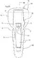
- a pillar base 1is fixed to the implant 60 by its connection device 3, and by means of a screw 61, then a cap 10 is fixed on the second coronal part of the abutment base.
- This assemblyis illustrated by the figure 23 and 24 .
- the cap 10comprises an opening 11 to form a connection part and a hollow interior volume, intended for the insertion of the second coronal part of the abutment base.
- the periphery of this opening 11comprises a surface 12 intended to bear against a corresponding flat surface of the flange 2 of the pillar base, after clipping the cap 10 onto the pillar base, to reach the assembled assembly shown by the figures 5 to 8 and 19a to 19d .
- connection devices different from the existing implantsin order to be able to have, for each existing implant, a pillar base equipped with a connection device 3 which is adapted to it.
- the advantage of this approachis that it makes it possible to keep the entire second coronal part of the pillar bases, starting from the collar 2, unchanged, whatever the implant corresponding to the pillar base.
- the function of the cap 10is to be housed within the incised gum, after fixing an implant, by fixing, preferably removable, on a pillar base connected to the implant.
- the final configurationis shown on the figure 24 .
- the implant 60is secured to the bone part 62
- the pillar base 1is fixed on the implant 60, so that its collar 2 is positioned at the level of the border between the bony part 62 and the gum 63.
- the cap 10covers the base of the abutment 1 as far as the collar 2, so that the gum 63 is almost exclusively in contact with the cap 10.
- the assembly formed by the assembly of a cap on a piler basethus corresponds to a healing assembly, which temporarily participates in the restoration process, allowing smooth healing and manufacturing of the final prosthesis, as will be detailed later.
- the gingiva 63therefore heals around the lateral surface 13 of the cap 10.
- this lateral surface 13is chosen to best correspond to the oral environment of the patient.
- the end surface 14 opposite the opening 11 of the capis intended to remain visible above the gingival surface 64 of the gum 63, or at least partially visible, since the gum remains mainly in contact with the lateral surface 13 of the cap. .
- at least part of end surface 14 and possibly an upper part of side surface 13therefore form an emerging surface of the cap.
- This emergent surfaceis particularly illustrated by the figures 25 and 26 .
- caps of different heightscan be provided to adapt to different configurations of the oral geometry. As examples of embodiments, three different standard heights allow good adaptation to all situations. This height is advantageously between 3 and 7 mm. Due to the use of a pillar base which plays the role of interface, the same cap 10 is thus universally suitable for all existing implants.
- the shape of the capis specifically chosen to promote the healing of the gums, according to an anatomical shape corresponding best to the tooth to be replaced and consequently also to the future prosthesis intended to occupy this space. oral.
- This shapeis in particular characterized by the planar section of its lateral surface 13, this section being a transverse section by a plane P perpendicular to the lateral surface 13, represented on the figure 23 , and substantially parallel to the terminal surface 14.
- this sectionis substantially reproduced by the shape of the terminal surface 14, or more precisely by the projection of this terminal surface 14 on such a perpendicular plane, i.e. say substantially parallel to the gingival surface 64.
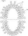
- the figure 9illustrates a top view of the upper and lower teeth and the figure 10 illustrates a sectional view at the level of the justogingival plane PJ of a dentition, represented on the figure 24 , at the level of the root of the emergences of the teeth.
- the teethhave sections of different shapes, which can be simplified by rectangular and/or square and/or triangular shapes, but more precisely trapezoidal.
- FIG. 11thus represents a top view of the sections of all the teeth and a top view of caps 10 associated with each tooth.
- the shapes of the different series of teethnumbered from 11 to 18, from 21 to 28, from 31 to 38 and from 41 to 48 in this figure, these numbers not to be confused with the numerical references used elsewhere in the other figures to designate the characteristics of the invention, are all approximated by means of four different caps 10, referenced A to D. For certain teeth, or even all the teeth, several caps, among the caps A to D, appear suitable.
- a healing element that is the subject of the inventionmay either correspond either to the assembly formed by a pillar base and by one of the caps of the series fixed on the base pillar opposite its connection to the dental implant, or to a unitary healing element directly attached to the dental implant 60 without using the pillar base.
- a series of healing elementswill be such that the healing elements which compose it have different heights between them and/or have cross sections of their lateral surfaces 13 or projections on a parallel plane of their emergent or terminal surfaces different from each other.
- the cross sections of the lateral surfaces 13 or the projections on a parallel plane of their emerging or terminal surfaces 14are each of: a substantially trapezoidal shape or a substantially polygonal or triangular shape , or square, or rectangular, or ovoid, or a substantially polygonal shape with rounded corners, or cylindrical.
- caps Aare suitable for treating the restoration of the upper lateral incisors and all the lower incisors.
- Caps Bare suitable for the restoration of canines and premolars
- caps Care suitable for the restoration of intermediate molars
- caps Dare suitable for the restoration of the largest molars.
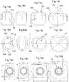
- the end surfaces 14 of these caps 10(A to D), intended for positioning above the gingival emergence, are substantially flat and intended for positioning parallel to a horizontal plane (parallel to the justa-gingival plane PJ, between 1 and 2 mm inclusive above this plane) corresponding to the cutting plane of the figure 9 . They are however slightly domed, having a central part 145, more particularly visible on the figures 14a to 14d , intended to rise further beyond the gum than its peripheral parts 146.
- the transverse section of the capby a plane P perpendicular to its lateral surface 13, as explained previously, which gives the final shape to the gum after healing, is substantially reproduced by the end surface 14 of the cap, which comes in its extension.
- the sections of all the capsall have a substantially trapezoidal shape. They include a long side 141, which will be arranged on the side outside the mouth (vestibular side), a small opposite parallel side 142, which will be arranged on the side inside the mouth (lingual side), connected by two sides 143, 144. The intersection of the diagonals of the trapezoid makes it possible to define a center 15.
- the center 17 of the substantially circular opening 11 of the opposite surface of the cap 10it is possible to define an axis 18 center of the cap, passing through the two central points 15, 17.
- This axis 18 of the cap 10is perpendicular to the end surface 14.
- the entire architecture of the pillar base and of an associated cap 10is designed so that the axis 18 of the cap corresponds to the longitudinal axis L of the pillar base, and to the axis of the implant.
- caps 10, A, B, C and Dtherefore differ in particular by the trapezoidal shape of the transverse section of their lateral surfaces 13.
- the trapezium of the smallest cap Aapproaches a triangle, because its small side 142 is very reduced.
- the trapezoid of cap Bapproximates a rectangle, the long side of which runs from the outside of the mouth inward, and corresponds to sides 143, 144.
- the trapezoids of caps C and Dapproximate d a rectangle, or even a square, the long side of which is in the opposite direction, and corresponds to the sides 141, 142, which are of similar but slightly different lengths.
- the figures 16a to 16dgive orders of magnitude of the dimensions of these caps, in millimetres.
- each capdisregarding the markers arranged on this surface and which will be described later, has a continuous surface, without reliefs, and / or without hollow part, and / or without groove, and / or without edges, and/or without asperity.
- This surfaceis convex. In particular, it does not have a hollow shape, and naturally no emerging (through) opening, as would be necessary if it were chosen to fix the cap by a fixing screw.
- This geometry without asperityis favorable to oral hygiene, preventing for example the accumulation of food and the deposit of dental plaque.
- the series of capscould comprise a different number of different geometries, for example at least three, or even at least two.
- a single form of capcould be suitable for all the teeth.
- the cross section of a cap at the level of its lateral surface 13could approach any polygon, such as a polygon with three, five or six sides.
- the corners of these polygonscould be so rounded that the overall shape would approach an oblong shape, or even an ovoid section, or even any other shape. furthest from a polygon.
- this shapecomprises at least one center or point perfectly defined geometrically to define a center 15, or even a possible axis 18 of the cap, this center being advantageously, but not necessarily, in alignment with the longitudinal axis L of the pillar base.
- the geometry of the visible emerging surface of the cap on the inside of the mouth sidediffers from the geometry on the outside side, to take account of the curvature of the gum.
- This shape of the emerging surface of the capis therefore asymmetrical with respect to a median plane containing the tangent T of the gum and passing through the center of the cap, called the median tangent plane; this tangent T (and therefore the projection of the median tangent plane) is represented on the figures 15a to 15d and more specifically on the figure 9 considering a 50 tooth to be restored.
- This median plane, called the tangent plane Tis parallel to the tangent T to the gum, perpendicular to the justogingival plane PJ, passes through the middle of a cap.
- a circular section shape for the section of the capis unsuitable. More generally, any planar section with symmetry around a point or an axis is little or not suitable for the aforementioned section of the cap, since it would not be adapted to the anatomy of the mouth.
- the emerging and visible surface of the cap, in particular the terminal surface 14is therefore generally not symmetrical with respect to at least one, or even several planes comprising its axis 18. It is not symmetrical with respect to relative to at least one or more planes perpendicular to the end surface 14 and passing through its center 15.
- a perpendicular median planea plane corresponding to a definition given above.
- Such a planeis substantially perpendicular to the end surface 14 of the healing element, and therefore also substantially perpendicular at the justogingival plane forming the final surface of the gum, from which emerge the teeth. It passes through the center of the terminal surface 14.
- a perpendicular median planecan be defined as any plane containing the axis 18 of the cap. In the example represented, particularly visible on the figures 15a to 15d , only the median plane perpendicular to the tangent plane T mentioned, passing through the middle of the two sides 141, 142, forms a plane of symmetry.
- the end surfaces 14 of the capsare extended from their periphery 146 by the lateral surface 13 around which the gums mainly heal, and which thus gives the shape of the gums adapted to the future prosthesis.
- This side surface 13has several surfaces 131, 132, 133, 134, substantially flat, possibly slightly curved, extending in a direction substantially parallel to the axis 18 of the cap and / or parallel to the longitudinal axis L of the pillar base, respectively extending the different sides 141, 142, 143, 144 of the end surface 14 of the cap.
- the interfaces between the terminal surface 14 and these different parts of the lateral surface 13are produced by rounded surfaces, without asperity, in particular convex.
- the side surface 13 of the capsends in a substantially frustoconical surface 19, up to the substantially circular opening 11, mentioned above.
- This opening 11leads to a hollow part internal to the cap 10, which allows the housing of the second coronal part of the pillar base.
- This hollow partis provided with a fixing device complementary to that 4 of the pillar base. In the embodiment, these are beads provided to clip onto the grooves 5 of the pillar base.
- a substantially longitudinal groove 16is arranged in this hollow part of the cap, to cooperate with the lug, thus forming a connection locked in rotation, and perfectly indexed, the orientation of the cap being unique and perfectly imposed.
- the figures 3 to 8 and 17a to 17d , 18a to 18d and 19a to 19dshow in particular a healing assembly according to the invention, formed by assembling a cap 10 with a pillar base 1.
- the capcan be formed from a plastic material, compatible with medical use, and pink, white or cream in color. Alternatively, it may be metal, for example titanium, or may be zirconia.
- the use of healing capstherefore makes it possible to promote ideal healing of the gingiva in a dental restoration procedure, as has been discussed, due to its geometry designed in phase with the oral anatomy.
- the solutionhas been described with a removable healing cap separate from a base in the previous embodiment.
- this healing elementcan alternatively be completely subgingival and invisible, then made visible by intervention on the gum to implement the rest of the recognition process which is described below. In this case, the end part of the cap will always be improperly called the emergent part.
- the cap 10will also be more generally referred to as the "healing element" 10 below.
- the emerging surfaceformed by the terminal surface 14 and optionally the upper part of the lateral surface 13, advantageously comprises at least two informative markers allowing the identification of at least two characteristics of the healing cap 10 and/or indirectly from the abutment base 1 and/or the dental implant 60.
- the arrangement of such informative markers on the healing cap 10makes it possible not to have recourse to a technique for taking traditional impression on the implant and to reduce the time required and the complexity to then develop the dental restoration abutment which will be placed to replace the healing cap 10 and the abutment base 1, and on which will be arranged the final prosthesis.
- said at least two informative markerscomprise a first type of informative marking of a first characteristic of the healing cap 10 and a second type of informative marking of a second characteristic of the healing cap 10.
- first and second characteristics linked to the healing cap 10are in particular the height of the healing element 10 and/or the shape of the healing cap 10, in particular the shape and the dimensions of the transverse section of its lateral surface 13 or of the projection on a plane parallel to the emerging surface.
- a markercan make it possible to deduce information on the abutment base and possibly on the implant, such as their orientation, which can be linked to the orientation of the cap.
- the characterization of the negative informative markerwhich is for example a simple hole, is for example its position relative to the rest of the cap 10 in which it is formed, its size, its shape or the number of such markers negative information.
- These characteristics of each negative informative markerprecisely make it possible to characterize the characteristic of the healing cap 10 and/or of the abutment base 1 characterized by the negative informative marker(s), such as for example the height of the healing element. For example, the position in height of the pillar base 1 can then be deduced therefrom.
- these same characteristicscan be deduced from the characterization of the positive informative marker, which is for example its position relative to the rest of the cap 10 in which it is formed, its size, its shape or the number of such positive informative markers.
- These characteristics of each positive informative markerprecisely make it possible to characterize the characteristic of the healing cap 10 and/or of the abutment base 1 and therefore of the dental implant 60 characterized by the informative marker(s) positive(s).
- Another example of such uniquely shaped and identifiable informative markersis a notch formed directly into the healing cap 10 itself.
- the joint presence of two such notches and the distance separating themcan be used to indicate, for example, the position and the type of abutment base and, by relation, the dental implant 60.
- a third example of such informative markers of particular and identifiable shapesis a line, such as an engraving or a relief, integral with the healing cap 10. The dimension, the position of this line and/or the number of such lines can be used to characterize an additional characteristic of the healing cap 10 and/or of the abutment base 1 and therefore of the dental implant 60.
- a practitionercan take a digital impression of the patient's mouth, without removing the healing element (the cap).
- the scan dataobtained by any device such as an oral scanner for example, is automatically transmitted to a computer equipped with dental restoration software.
- This softwareis equipped with a man-machine interface, by which an operator can indicate the cap model he has used, or more generally the reference of the healing element, and possibly of the implant and/or the abutment base used.
- the informative markerscan be indicated to the software by the operator himself or identified automatically by the software by any means of detection, recognition and identification adapted according to the nature of the marker and its characterization.
- the healing elementFrom the scan data and the informative markers, software automatically determines the axis of the healing element, by geometric construction, for example from the identification of the center of the cap and the direction perpendicular to the surface terminal 14 passing through this center 15, then its orientation and the space it occupies, using the markers. In particular, he can thus automatically determine the axis of the implant, without having to visualize it directly.
- the healing elementis advantageously aligned with the implant, its axis thus being coincident with that of the implant.
- connection device 3 of the abutment base with the implantit is possible to deduce from the informative markers the orientation of the axis of the connection device with the implant, for example the connection device 3 of the abutment base with the implant: this makes it possible to automatically deduce the positioning of the implant connection device, without having to visualize it directly, from knowledge of the abutment base.
- a first approachmay consist in forming different colored healing elements for different heights.
- a second approachconsists in providing and identifying at least one informative marker on the healing element to indicate this height.
- an operatorenters the reference of the healing element via a man-machine interface, which allows the software to find certain characteristics of this healing element, in confirmation or in addition to those obtained by the markers , such as its height, center and/or axis, in a library present in the form of a database stored in a memory electronics that he can consult.
- the figure 20illustrates by way of example a virtual cap 10' stored in the library associated with the restoration software.
- a marker in space 51'is associated with the cap, allowing its positioning in space.
- the softwarecan automatically recognize the healing element from its informative markers, or even from its other geometric characteristics, without manual entry of its reference.
- An operatorcan assist software with the correct positioning of the marker 51 of the real cap, that is to say the recognition of its real position, by entering on an image obtained by the digitization step mentioned above and presented to the operator on a screen of a man-machine interface one or more points of the emerging surface.
- the softwareFrom the digitized data, and possibly with the help of the point(s) on the surface of the healing element manually entered by an operator, the software therefore knows how to associate the virtual healing element from its library with the environment. digitized buccal, replacing the actual healing element, to obtain a more perfect digital reproduction. As shown on the figure 21 , the real mark 51 of the real cap 10 is thus determined automatically by the software. It is possible to perfectly position the virtual healing element on the digital impression, automatically or possibly through the intervention of an operator on a man-machine interface allowing to visualize the buccal impression and the element of healing.
- This perfect positioning of the virtual healing elementmakes it possible to deduce therefrom all the neighboring geometries, from the known references stored in the database associated with the precise healing element considered, including the position of the implant 60 and the geometry of the healed gingiva without the presence of the cap 10 or of the abutment base, as represented by the figure 22 .
- the markers usedare sufficient to provide the data necessary for the correct positioning of the cap without recourse to a library.
- the restoration softwarewhen the restoration software has repositioned the positioning of the hidden implant with precision, it deduces from this knowledge the final geometry of the restoration abutment to be manufactured, which must be fixed to the implant and occupy the entire volume. gingiva defined by the healing element, then the geometry of the dental prosthesis intended to be fixed on this pillar, in a known manner.
- this restoration processcan be done totally digitally, therefore virtually, totally or partially automated, or include construction phases of a plastic or plaster model.
- a physical impressionfor example in silicone, can be made, plaster can be poured into the impression to create the master model, i.e. a replica of the dental arch to be restored, which is then scanned in the laboratory to reconstruct a digital image.
- a restoration devicewhich comprises a central processing and control unit, here comprising at least one microprocessor, linked to an electronic memory, on which is executed software allowing the implementation of all or part of the steps of the restoration method described above.
- This central unitis linked by a communication device to a module for obtaining digital data representing all or part of a patient's dentition, which may consist of a device such as an oral scanner. It is also linked to a man-machine interface, comprising for example a screen and/or a keyboard, to allow exchanges with an operator, as explained above.
- the central unitthen carries out all the necessary processing, calculations and the like, by means of software.
- itis capable of generating and transmitting manufacturing commands to a device for manufacturing a restoration and/or prosthesis pillar. It can also be linked by a second communication device to a manufacturing device such as a machine tool.
Landscapes
- Health & Medical Sciences (AREA)
- Animal Behavior & Ethology (AREA)
- Veterinary Medicine (AREA)
- Life Sciences & Earth Sciences (AREA)
- Oral & Maxillofacial Surgery (AREA)
- General Health & Medical Sciences (AREA)
- Epidemiology (AREA)
- Public Health (AREA)
- Dentistry (AREA)
- Orthopedic Medicine & Surgery (AREA)
- Dermatology (AREA)
- Transplantation (AREA)
- Chemical & Material Sciences (AREA)
- Medicinal Chemistry (AREA)
- Dental Prosthetics (AREA)
- Dental Preparations (AREA)
- Prostheses (AREA)
Abstract
Translated fromFrench
Description
Translated fromFrenchLa présente invention se rapporte à un élément de cicatrisation pour une restauration dentaire et à un ensemble de cicatrisation comprenant un tel élément de cicatrisation. Elle concerne aussi une méthode de fabrication d'un pilier de restauration dentaire et/ou d'une prothèse basée sur un tel élément de cicatrisation.The present invention relates to a healing element for a dental restoration and to a healing assembly comprising such a healing element. It also relates to a method of manufacturing a dental restoration pillar and/or a prosthesis based on such a healing element.
La restauration dentaire permet de réaliser une dentition artificielle à un patient partiellement ou totalement édenté. Elle repose sur l'intégration d'un ou plusieurs implants dans la structure osseuse, pratiquée par une incision de la gencive afin d'atteindre la structure osseuse et de la percer. Ensuite, un élément de cicatrisation est en général fixé sur un implant et cet ensemble reste intouché jusqu'à solidarisation de l'implant dans la structure osseuse par ostéointégration et cicatrisation de la gencive autour de l'élément de cicatrisation. La restauration dentaire peut être finalisée par la fixation d'un pilier de restauration sur l'implant, sur lequel est fixée la prothèse dentaire, ou en variante la fixation d'une prothèse dentaire directement sur l'implant. Le pilier et la prothèse dentaire sont personnalisés, adaptés à l'anatomie du patient et à la dent à remplacer, pour atteindre un résultat aussi proche que possible de la dentition naturelle idéale. Pour cela, le volume précis de l'espace à restaurer est en général pris en compte, par une prise d'empreinte, qui permet la fabrication personnalisée de la prothèse dentaire.Dental restoration allows artificial dentition to be made for a partially or totally edentulous patient. It is based on the integration of one or more implants into the bone structure, performed through an incision in the gums in order to reach the bone structure and pierce it. Then, a healing element is generally attached to an implant and this assembly remains untouched until the implant is solidified in the bone structure by osseointegration and healing of the gums around the healing element. The dental restoration can be finalized by fixing a restoration pillar on the implant, on which the dental prosthesis is fixed, or alternatively fixing a dental prosthesis directly on the implant. The abutment and the dental prosthesis are personalized, adapted to the patient's anatomy and the tooth to be replaced, to achieve a result as close as possible to the ideal natural dentition. For this, the precise volume of the space to be restored is generally taken into account, by taking an impression, which allows the personalized manufacture of the dental prosthesis.
Dans l'état de la technique, les méthodes existantes de restauration dentaire se heurtent à tout ou partie des problèmes techniques suivants :
- dans de nombreux procédés existants, une nouvelle intervention sur la gencive est réalisée après sa cicatrisation suite à la pause d'implant, pour réaliser l'empreinte, matérielle ou numérique, de l'espace à restaurer, tout en ayant une vue de l'implant et de la gencive pour prendre en compte précisément l'ensemble de cette géométrie, dans le but de fabriquer un pilier et une prothèse de formes précises : cette approche est naturellement traumatisante ;
- d'autres procédés existants limitent ce traumatisme en utilisant des composants de cicatrisation qui ne sont pas retirés lors d'une prise d'empreinte, pour ne pas heurter la gencive : en contrepartie, ces procédés utilisent des éléments cicatrisants particuliers, en général de forme cylindrique et standard et intégrant parfois des composants complémentaires pour permettre la prise en compte de tout ou partie de la géométrie au-dessus de l'implant sans y avoir totalement accès par une prise d'empreinte. Ces méthodes moins traumatisantes présentent alors d'autres inconvénients, de complexité et/ou de moins bonne optimisation de la phase de cicatrisation.
- in many existing processes, a new intervention on the gum is carried out after its healing following the implant break, to make the impression, material or digital, of the space to be restored, while having a view of the implant and gingiva to precisely take into account all of this geometry, with the aim of manufacturing a pillar and a prosthesis of precise shapes: this approach is naturally traumatic;
- other existing methods limit this trauma by using healing components which are not removed during an impression, so as not to hit the gums: in return, these methods use particular healing elements, generally of the shape cylindrical and standard and sometimes incorporating additional components to allow all or part of the geometry above the implant to be taken into account without having full access to it by taking an impression. These less traumatic methods then have other drawbacks, of complexity and/or less good optimization of the healing phase.
Ainsi, un objet général de l'invention consiste en une solution de restauration dentaire qui ne comprend pas tout ou partie des inconvénients de l'état de la technique.Thus, a general object of the invention consists of a dental restoration solution which does not include all or part of the disadvantages of the state of the art.
Plus précisément, un premier objet de l'invention est une solution de restauration dentaire qui minimise le traumatisme du patient lors du procédé de restauration.More specifically, a first object of the invention is a dental restorative solution which minimizes patient trauma during the restorative process.
Un second objet de l'invention est une solution de restauration dentaire qui permet une restauration la plus adaptée possible à l'anatomie du patient.A second object of the invention is a dental restoration solution which allows a restoration that is as adapted as possible to the anatomy of the patient.
Un troisième objet de l'invention est une solution de restauration dentaire la plus universelle possible, adaptée à tout implant et toute restauration.A third object of the invention is a dental restoration solution that is as universal as possible, suitable for any implant and any restoration.
Un quatrième objet de l'invention est une solution de restauration dentaire la plus simple possible.A fourth object of the invention is the simplest possible dental restoration solution.
A cet effet, l'invention repose sur un élément de cicatrisation apte à une connexion avec un implant dentaire, comprenant une surface latérale destinée à une intégration au sein d'une gencive pour mettre en forme la gencive lors de sa cicatrisation, et une surface terminale, caractérisé en ce qu'une partie de la surface latérale et de la surface terminale forment une surface émergente, qui est asymétrique par rapport à au moins un plan médian perpendiculaire et en ce que la surface émergente comprend au moins deux marqueurs informatifs permettant l'identification d'au moins deux caractéristiques dudit élément de cicatrisation et/ou d'une embase de pilier et/ou dudit implant dentaire sur lequel il serait connecté.To this end, the invention is based on a healing element suitable for connection with a dental implant, comprising a lateral surface intended for integration within a gum to shape the gum during its healing, and a surface terminal surface, characterized in that a part of the lateral surface and of the terminal surface form an emerging surface, which is asymmetrical with respect to at least one perpendicular median plane and in that the emerging surface comprises at least two informative markers allowing the identification of at least two characteristics of said healing element and/or of a pillar base and/or of said dental implant to which it would be connected.
La surface émergente de l'élément de cicatrisation peut être asymétrique par rapport à au moins un plan médian perpendiculaire à la surface émergente et passant par le centre de la surface émergente ou comprenant un axe central de l'élément de cicatrisation.The emerging surface of the healing element can be asymmetrical with respect to at least one median plane perpendicular to the emerging surface and passing through the center of the emerging surface or including a central axis of the healing element.
Une section transverse à la surface latérale de l'élément de cicatrisation ou une projection sur un plan parallèle à la surface terminale de la surface émergente de l'élément de cicatrisation peut présenter :
- une forme sensiblement trapézoïdale ou une forme sensiblement polygonale, ou triangulaire, ou carrée, ou rectangulaire, ou ovoïde, ou une forme sensiblement polygonale avec des angles arrondis ; et/ou
- une partie destinée à un positionnement orienté vers l'extérieur de la bouche de plus grande dimension qu'une partie destinée à un positionnement orienté vers l'intérieur.
- a substantially trapezoidal shape or a substantially polygonal, or triangular, or square, or rectangular, or ovoid shape, or a substantially polygonal shape with rounded corners; and or
- a part intended for positioning oriented towards the outside of the mouth of larger dimension than a part intended for positioning oriented towards the inside.
La surface terminale de l'élément de cicatrisation et/ou sa surface émergente peut présenter :
- une surface non plane, courbée ; et/ou
- une surface convexe ; et/ou
- une surface sans aspérité en dehors des marqueurs informatifs ; et/ou
- une surface sans ouverture débouchante.
- a non-flat, curved surface; and or
- a convex surface; and or
- a smooth surface apart from the informative markers; and or
- a surface without a through opening.
Lesdites caractéristiques identifiées par les marqueurs informatifs peuvent comprendre un ou plusieurs éléments parmi :
- la hauteur de l'élément de cicatrisation,
- la forme de l'élément de cicatrisation, notamment la forme et les dimensions de la section transverse de sa surface latérale ou de la projection sur un plan parallèle de la surface émergente,
- les dimensions de la partie de liaison de l'élément de cicatrisation avec une embase de pilier, et indirectement d'un l'implant dentaire,
- l'orientation dudit implant dentaire, par l'intermédiaire de l'orientation de l'élément de cicatrisation.
- the height of the healing element,
- the shape of the healing element, in particular the shape and dimensions of the cross section of its lateral surface or of the projection on a parallel plane of the emerging surface,
- the dimensions of the connecting part of the healing element with a pillar base, and indirectly of a dental implant,
- the orientation of said dental implant, through the orientation of the healing element.
Lesdits au moins deux marqueurs informatifs peuvent comprendre un premier type de marquage informatif d'une première caractéristique de l'élément de cicatrisation et un deuxième type de marquage informatif d'une deuxième caractéristique distincte de l'élément de cicatrisation.Said at least two informative markers can comprise a first type of informative marking of a first characteristic of the healing element and a second type of informative marking of a second distinct characteristic of the healing element.
Chaque marqueur informatif peut appartenir à l'un des types suivants :
- un marqueur informatif négatif, notamment en creux dans l'une des surfaces de l'élément de cicatrisation,
- un marqueur informatif positif, notamment en relief sur l'une des surfaces de l'élément de cicatrisation,
- un marqueur informatif de forme particulière et identifiable formée dans l'une des surfaces de l'élément de cicatrisation, notamment de forme polygonale ou de ligne,
- un marqueur informatif constitué par une valeur numérique lisible ou par un code d'identification lisible tel qu'un code barres ou un code datamatrix,
- une puce RFID.
- a negative informative marker, in particular recessed in one of the surfaces of the healing element,
- a positive informative marker, in particular in relief on one of the surfaces of the healing element,
- an informative marker of particular and identifiable shape formed in one of the surfaces of the healing element, in particular of polygonal or line shape,
- an informative marker consisting of a readable numerical value or a readable identification code such as a bar code or a datamatrix code,
- an RFID chip.
L'invention porte aussi sur une série d'éléments de cicatrisation, caractérisée en ce qu'elle comprend au moins deux éléments de cicatrisation tels que décrits précédemment présentant des formes différentes, ou en ce qu'elle comprend au moins trois éléments de cicatrisation de formes différentes.The invention also relates to a series of healing elements, characterized in that it comprises at least two healing elements as described previously having different shapes, or in that it comprises at least three healing elements of different shapes.
Lesdits au moins deux ou au moins trois éléments de cicatrisation peuvent présenter des hauteurs différentes entre eux et/ou présenter des sections transverses de leurs surfaces latérales ou des projections sur un plan parallèle de leurs surfaces terminales différentes entre elles.Said at least two or at least three healing elements may have different heights from one another and/or have cross sections of their lateral surfaces or projections on a parallel plane of their end surfaces that are different from one another.
L'invention porte aussi sur un ensemble de cicatrisation apte à une connexion avec un implant dentaire lors d'une phase de cicatrisation d'un procédé de restauration dentaire, caractérisé en ce qu'il comprend un élément de cicatrisation tel que décrit précédemment destiné à être entouré au moins partiellement par une gencive et une embase de pilier destinée à une fixation dans un implant, l'embase de pilier comprenant un axe longitudinal sur toute sa longueur apte à un alignement avec l'axe dudit implant.The invention also relates to a healing assembly suitable for connection with a dental implant during a healing phase of a dental restoration process, characterized in that it comprises a healing element as described previously intended to be surrounded at least partially by a gingiva and a pillar base intended for fixing in an implant, the pillar base comprising a longitudinal axis over its entire length suitable for alignment with the axis of said implant.
L'embase de pilier peut présenter une symétrie ou une quasi-symétrie autour de son axe longitudinal.The pillar base may have symmetry or quasi-symmetry around its longitudinal axis.
L'élément de cicatrisation et l'embase de pilier peuvent former deux éléments distincts et assemblés de manière amovible, notamment par clippage, et
- l'embase de pilier peut comprendre un dispositif de connexion avec un implant et un dispositif de connexion avec l'élément de cicatrisation, ces deux dispositifs de connexion étant agencés autour d'un axe aligné et confondu avec l'axe longitudinal de l'embase de pilier, et
- l'élément de cicatrisation peut être agencé autour d'un axe central aligné avec l'axe longitudinal de l'embase de pilier.
- the abutment base may comprise a device for connection with an implant and a device for connection with the healing element, these two connection devices being arranged around an axis aligned and coinciding with the longitudinal axis of the pillar base, and
- the healing element can be arranged around a central axis aligned with the longitudinal axis of the pillar base.
L'élément de cicatrisation peut comprendre un élément anti-rotationnel, notamment une gorge, pour coopérer avec un élément anti-rotationnel, notamment un ergot, de l'embase de pilier, et garantir une fixation de l'élément de cicatrisation à orientation unique, sans rotation autour de l'embase de pilier.The healing element may comprise an anti-rotational element, in particular a groove, to cooperate with an anti-rotational element, in particular a lug, of the abutment base, and guarantee fixing of the healing element with a single orientation , without rotation around the abutment base.
Lesdits au moins deux marqueurs informatifs de l'élément de cicatrisation peuvent comprendre un premier marquage informatif d'une première caractéristique de l'embase de pilier et un deuxième marquage informatif d'une deuxième caractéristique de l'embase de pilier.Said at least two informative markers of the healing element can comprise a first informative marking of a first characteristic of the abutment base and a second informative marking of a second characteristic of the abutment base.
L'invention porte aussi sur un procédé de fabrication d'un pilier de restauration dentaire et/ou d'une prothèse, destiné à être fixé sur un implant dentaire sur une première extrémité, caractérisé en ce qu'il comprend les étapes suivantes :
- réalisation d'une empreinte physique ou numérique de l'espace buccal comprenant un élément de cicatrisation tel que décrit précédemment fixé sur l'implant dentaire ou un ensemble de cicatrisation tel que décrit précédemment fixé sur l'implant dentaire,
- détermination automatique et/ou à partir de données saisies sur une interface homme machine par un opérateur du positionnement de l'implant dentaire et de l'espace buccal, à partir de ladite empreinte et des marqueurs informatifs de l'élément de cicatrisation.
- production of a physical or digital impression of the oral space comprising a healing element as described above fixed to the dental implant or a healing assembly as described above fixed to the dental implant,
- automatic determination and/or from data entered on a man-machine interface by an operator of the positioning of the dental implant and of the oral space, from said impression and informative markers of the healing element.
L'invention est précisément définie par les revendications.The invention is precisely defined by the claims.
Ces objets, caractéristiques et avantages de la présente invention seront exposés en détail dans la description suivante d'un mode d'exécution particulier fait à titre non-limitatif en relation avec les figures jointes parmi lesquelles :
- Les
figures 1 représentent respectivement des vues en perspective d'une embase de pilier utilisée dans un procédé de restauration selon un mode de réalisation de l'invention.et 2 - Les
figures 3 représentent respectivement des vues en perspective d'une phase intermédiaire d'association d'un capuchon sur une embase de pilier dans un procédé de restauration selon le mode de réalisation de l'invention.et 4 - Les
figures 5 représentent respectivement des vues en perspective de l'ensemble obtenu après fixation d'un capuchon sur une embase de pilier dans un procédé de restauration selon le mode de réalisation de l'invention.et 6 - Les
figures 7 représentent respectivement des mêmes vues en perspective sur lesquelles le capuchon est représenté en transparence pour visualiser l'embase de pilier.et 8 - La
figure 9 représente les dents inférieures et supérieures en vue de dessus. - La
figure 10 représente une vue des dents selon une section justa-gingivale. - La
figure 11 représente une section horizontale de la dentition au niveau justa-gingival ainsi que les capuchons correspondants retenus selon le mode de réalisation de l'invention. - Les
figures 12a à 12d et 13a à 13d représentent respectivement des vues en perspective de dessus et de dessous d'une série de capuchons selon le mode de réalisation de l'invention. - Les
figures 14a à 14d représentent respectivement des vues de côté de la série de capuchons selon le mode de réalisation de l'invention. - Les
figures 15a à 15d représentent respectivement des vues de dessus de la série de capuchons selon le mode de réalisation de l'invention. - Les
figures 16a à 16d représentent respectivement des vues de dessous de la série de capuchons selon le mode de réalisation de l'invention. - Les
figures 17a à 17d et 18a à 18d représentent respectivement des vues en perspective de dessus et de dessous d'une phase intermédiaire d'association de la série de capuchons avec des embases de pilier dans un procédé de restauration selon le mode de réalisation de l'invention. - Les
figures 19a à 19d représentent respectivement des vues de côté de la série de capuchons assemblés avec des embases de pilier selon le mode de réalisation de l'invention. - Les
figures 20 à 22 représentent des vues en coupe par un plan médian vertical illustrant des étapes du procédé de restauration selon un mode de réalisation de l'invention. - La
figure 23 illustre une vue en coupe d'un capuchon selon le mode de réalisation de l'invention disposé sur une embase de pilier fixée dans un implant. - La
figure 24 illustre une vue en coupe d'un ensemble de cicatrisation comprenant un capuchon entouré de la gencive et disposé sur une embase de pilier fixée dans un implant selon le mode de réalisation de l'invention. - Les
figures 25 et 26 représentent deux vues schématiques d'une gencive en coupe au sein de laquelle est fixé un ensemble de cicatrisation selon le mode de réalisation de l'invention.
- The
figures 1 and 2 respectively show perspective views of a pillar base used in a restoration method according to one embodiment of the invention. - The
figures 3 and 4 respectively represent perspective views of an intermediate phase of association of a cap on a pillar base in a restoration method according to the embodiment of the invention. - The
figures 5 and 6 respectively represent perspective views of the assembly obtained after fixing a cap on a pillar base in a restoration method according to the embodiment of the invention. - The
figures 7 and 8 respectively represent the same perspective views on which the cap is shown in transparency to visualize the abutment base. - The
figure 9 shows the lower and upper teeth in top view. - The
figure 10 represents a view of the teeth according to a justa-gingival section. - The
figure 11 represents a horizontal section of the dentition at the justa-gingival level as well as the corresponding caps retained according to the embodiment of the invention. - The
figures 12a to 12d and 13a to 13d show respectively top and bottom perspective views of a series of caps according to the embodiment of the invention. - The
figures 14a to 14d respectively show side views of the series of caps according to the embodiment of the invention. - The
figures 15a to 15d respectively represent top views of the series of caps according to the embodiment of the invention. - The
figures 16a to 16d respectively represent bottom views of the series of caps according to the embodiment of the invention. - The
figures 17a to 17d and 18a to 18d represent respectively top and bottom perspective views of an intermediate phase of association of the series of caps with abutment bases in a restoration method according to the embodiment of the invention. - The
figures 19a to 19d respectively represent side views of the series of caps assembled with pillar bases according to the embodiment of the invention. - The
figures 20 to 22 show views in section through a vertical median plane illustrating steps of the restoration method according to one embodiment of the invention. - The
figure 23 illustrates a sectional view of a cap according to the embodiment of the invention placed on a pillar base fixed in an implant. - The
figure 24 illustrates a sectional view of a healing assembly comprising a cap surrounded by the gum and placed on a pillar base fixed in an implant according to the embodiment of the invention. - The
figures 25 and 26 represent two schematic views of a gingiva in section within which is fixed a healing assembly according to the embodiment of the invention.
Le procédé de restauration selon le mode de réalisation de l'invention comprend donc deux phases, comme explicité précédemment : une première phase dite de cicatrisation durant laquelle un ou plusieurs implant(s) sont intégrés dans la structure osseuse du patient par ostéointégration, et durant laquelle un capuchon de cicatrisation particulier associé à une embase de pilier sont utilisés, comme cela va être détaillé par la suite, puis une seconde phase de restauration en tant que telle, durant laquelle une prothèse définitive est mise en place sur le ou les implants par l'intermédiaire d'un pilier de restauration.The restoration method according to the embodiment of the invention therefore comprises two phases, as explained above: a first so-called healing phase during which one or more implant(s) are integrated into the patient's bone structure by osseointegration, and during which a particular healing cap associated with an abutment base are used, as will be detailed later, then a second phase of restoration as such, during which a definitive prosthesis is placed on the implant(s) by through a restoration pillar.
Selon le mode de réalisation de l'invention qui va être décrit, une restauration dentaire utilise, dans la première phase de cicatrisation, un composant intermédiaire que nous appellerons embase de pilier 1, qui est parfois appelé simplement pilier ou T-base ou Esthétibase. L'embase de pilier 1, particulièrement représentée sur les
En remarque, l'embase de pilier 1 utilisée est non définitive, participe à la première phase de cicatrisation uniquement, est de préférence retirée lors de la finalisation de la restauration et remplacée par un pilier de restauration définitif (qui peut se présenter sous la forme d'une autre embase). En variante, la même embase de pilier 1 est éventuellement retirée, nettoyée et réutilisée dans la restauration définitive, remplissant alors la seconde fonction de pilier de restauration.As a side note, the
De plus, l'embase de pilier 1 est de préférence universelle, et présente une forme symétrique ou plus précisément quasi symétrique (l'élément anti-rotationnel forme par exemple une exception à la symétrie) autour d'un axe longitudinal L qui forme un axe de révolution. Cet axe L forme donc notamment un axe central de symétrie du dispositif de connexion 3 avec un implant. Avantageusement, ce même axe L forme aussi un axe de symétrie du dispositif de connexion 4 avec un capuchon. L'embase de pilier 1 s'étend donc globalement selon une seule direction, identifiée par un axe longitudinal L unique. Nous pouvons donc plus généralement considérer que l'embase de pilier comprend un axe longitudinal L qui s'étend sur toute sa longueur, de manière apte à un alignement avec l'axe d'un implant 60. Notamment, les deux dispositifs de connexion 3, 4 de l'embase de pilier 1 sont agencés à des niveaux différents autour de ce même axe longitudinal L.In addition, the
Suite à la fixation d'un implant 60 lors d'un procédé de restauration dentaire, une embase de pilier 1 est fixée sur l'implant 60 par son dispositif de connexion 3, et par l'intermédiaire d'une vis 61, puis un capuchon 10 est fixé sur la seconde partie coronaire de l'embase de pilier. Cet assemblage est illustré par les
Il existe autant d'embases de pilier différentes que de dispositifs de connexion différents des implants existants, afin de pouvoir disposer, pour chaque implant existant, d'une embase de pilier dotée d'un dispositif de connexion 3 qui lui est adapté. L'avantage de cette approche est qu'elle permet de conserver toute la seconde partie coronaire des embases de pilier, à partir de la collerette 2, inchangée, quel que soit l'implant correspondant à l'embase de pilier. Naturellement, il est aussi possible de prévoir des secondes parties coronaires différentes pour des embases de pilier différentes, selon leur utilisation envisagée. Dans tous les cas, la seconde partie coronaire de l'embase de pilier est indépendante de l'implant, décorrélée du dispositif de fixation de l'implant.There are as many different abutment bases as there are connection devices different from the existing implants, in order to be able to have, for each existing implant, a pillar base equipped with a
Le capuchon 10 a pour fonction de venir se loger au sein de la gencive incisée, après fixation d'un implant, par fixation, de préférence amovible, sur une embase de pilier connectée à l'implant. La configuration finale est représentée sur la
La gencive 63 se cicatrise donc autour de la surface latérale 13 du capuchon 10. Pour cela, cette surface latérale 13 est choisie pour correspondre au mieux au milieu buccal du patient. La surface terminale 14 opposée à l'ouverture 11 du capuchon est destinée à rester visible au-dessus de la surface gingivale 64 de la gencive 63, ou au moins partiellement visible, puisque la gencive reste principalement en contact avec la surface latérale 13 du capuchon. En remarque, au moins une partie de la surface terminale 14 et éventuellement une partie haute de la surface latérale 13 forment donc une surface émergente du capuchon. Cette surface émergente est notamment illustrée par les
Selon le mode de réalisation de l'invention, la forme du capuchon est spécifiquement choisie pour favoriser la cicatrisation de la gencive, selon une forme anatomique correspondant au mieux à la dent à remplacer et par conséquent aussi à la future prothèse destinée à occuper cet espace buccal.According to the embodiment of the invention, the shape of the cap is specifically chosen to promote the healing of the gums, according to an anatomical shape corresponding best to the tooth to be replaced and consequently also to the future prosthesis intended to occupy this space. oral.
Cette forme est notamment caractérisée par la section plane de sa surface latérale 13, cette section étant une section transverse par un plan perpendiculaire P à la surface latérale 13, représenté sur la
Pour comprendre l'approche retenue, la
Selon le mode de réalisation choisi, une série de capuchons 10 de formes différentes va permettre de reproduire au mieux ces différentes formes. La
Comme il le sera détaillé plus loin, un élément de cicatrisation objet de l'invention pourra indifféremment correspondre soit à l'ensemble formé par une embase de pilier et par l'un des capuchons de la série fixé sur l'embase de pilier à l'opposé de sa liaison à l'implant dentaire, soit à un élément de cicatrisation unitaire directement fixé sur l'implant dentaire 60 sans utilisation de l'embase de pilier.As will be detailed later, a healing element that is the subject of the invention may either correspond either to the assembly formed by a pillar base and by one of the caps of the series fixed on the base pillar opposite its connection to the dental implant, or to a unitary healing element directly attached to the
Ainsi de manière plus générale, une série d'éléments de cicatrisation sera telle que les éléments de cicatrisation qui la composent présentent des hauteurs différentes entre eux et/ou présentent des sections transverses de leur surfaces latérales 13 ou des projections sur un plan parallèle de leurs surfaces émergentes ou terminales différentes entre eux.Thus, more generally, a series of healing elements will be such that the healing elements which compose it have different heights between them and/or have cross sections of their
Au sein d'une même série d'éléments de cicatrisation, les sections transverses des surfaces latérales 13 ou les projections sur un plan parallèle de leurs surfaces émergentes ou terminales 14 sont chacune parmi : une forme sensiblement trapézoïdale ou une forme sensiblement polygonale, ou triangulaire, ou carrée, ou rectangulaire, ou ovoïde, ou une forme sensiblement polygonale avec des angles arrondis, ou cylindrique.Within the same series of healing elements, the cross sections of the lateral surfaces 13 or the projections on a parallel plane of their emerging or
Dans l'exemple de réalisation choisi et illustré par la
Comme cela ressort des
La section transverse du capuchon, par un plan P perpendiculaire à sa surface latérale 13, comme explicité précédemment, qui donne la forme finale à la gencive après cicatrisation, est sensiblement reproduite par la surface terminale 14 du capuchon, qui vient dans son prolongement. Les sections de tous les capuchons présentent toutes une forme sensiblement trapézoïdale. Elles comprennent un grand côté 141, qui sera disposé du côté de l'extérieur de la bouche (côté vestibulaire), un petit côté 142 opposé parallèle, qui sera disposé du côté de l'intérieur de la bouche (côté lingual), reliés par deux côtés 143, 144. Le croisement des diagonales du trapèze permet de définir un centre 15. De plus, en considérant le centre 17 de l'ouverture 11 sensiblement circulaire de la surface opposée du capuchon 10, il est possible de définir un axe 18 central du capuchon, passant par les deux points centraux 15, 17. Cet axe 18 du capuchon 10 est perpendiculaire à la surface terminale 14. L'ensemble de l'architecture de l'embase de pilier et d'un capuchon 10 associés est conçu pour que l'axe 18 du capuchon corresponde à l'axe longitudinal L de l'embase de pilier, et à l'axe de l'implant.The transverse section of the cap, by a plane P perpendicular to its
Les quatre types de capuchons 10, A, B, C et D, diffèrent donc notamment par la forme trapézoïdale de la section transverse de leurs surfaces latérales 13. Le trapèze du plus petit capuchon A se rapproche d'un triangle, car son petit côté 142 est très réduit. Le trapèze du capuchon B se rapproche d'un rectangle, dont le grand côté va de l'extérieur de la bouche vers l'intérieur, et correspond aux côtés 143, 144. Au contraire, les trapèzes des capuchons C et D se rapprochent d'un rectangle, voire d'un carré, dont le grand côté est dans le sens inverse, et correspond aux côtés 141, 142, qui sont de longueur proches mais légèrement différentes. A titre d'exemples de réalisation, les
Naturellement, cette forme sensiblement trapézoïdale retenue présente des angles arrondis et des côtés courbés, pour garantir de ne pas heurter la gencive. De plus, la surface terminale 14 de chaque capuchon, en faisant abstraction des marqueurs agencés sur cette surface et qui seront décrits plus loin, présente une surface continue, sans reliefs, et/ou sans partie creuse, et/ou sans gorge, et/ou sans arrête, et/ou sans aspérité. Cette surface est convexe. Notamment, elle ne présente pas de forme creuse, et naturellement pas d'ouverture débouchante (traversante), comme cela serait nécessaire si il était choisi de fixer le capuchon par une vis de fixation. Cette géométrie sans aspérité est favorable à l'hygiène buccale, empêche par exemple l'accumulation d'aliments et le dépôt de la plaque dentaire.Naturally, this retained substantially trapezoidal shape has rounded corners and curved sides, to guarantee not to hit the gum. In addition, the
En variante, la série de capuchons pourrait comprendre un nombre différent de géométries différentes, par exemple au moins trois, voire au moins deux. Dans une variante de réalisation simplifiée, une seule forme de capuchon pourrait convenir pour toutes les dents.Alternatively, the series of caps could comprise a different number of different geometries, for example at least three, or even at least two. In a simplified alternative embodiment, a single form of cap could be suitable for all the teeth.
Selon d'autres variantes de réalisation, la section transverse d'un capuchon au niveau de sa surface latérale 13 pourrait s'approcher de tout polygone, comme un polygone à trois, cinq ou six côtés. En variante, les angles de ces polygones pourraient être si arrondis que la forme globale s'approcherait d'une forme oblongue, voire de section d'ovoïde, voire de toute autre forme plus éloignée d'un polygone. Avantageusement, cette forme comprend au moins un centre ou point parfaitement défini géométriquement pour définir un centre 15, voire un éventuel axe 18 du capuchon, ce centre étant avantageusement, mais non obligatoirement, dans l'alignement de l'axe longitudinal L de l'embase de pilier.According to other variant embodiments, the cross section of a cap at the level of its
Selon le mode de réalisation, la géométrie de la surface émergente visible du capuchon du côté de l'intérieur de la bouche diffère de la géométrie du côté de l'extérieur, pour tenir compte de la courbure de la gencive. Cette forme de la surface émergente du capuchon est donc asymétrique par rapport à un plan médian contenant la tangente T de la gencive et passant au centre du capuchon, dit plan tangent médian ; cette tangente T (et donc la projection du plan tangent médian) est représentée sur les
Ainsi, une forme de section circulaire pour la section du capuchon, associée par exemple à un capuchon cylindrique, est inadaptée. Plus généralement, toute section plane présentant une symétrie autour d'un point ou d'un axe est peu ou pas adaptée pour la section susmentionnée du capuchon, car elle ne serait pas adaptée à l'anatomie de la bouche. Pour les mêmes raisons, la surface émergente et visible du capuchon, notamment la surface terminale 14, n'est plus généralement donc pas symétrique par rapport à au moins un, ou même plusieurs plans comprenant son axe 18. Elle n'est pas symétrique par rapport à au moins un, ou plusieurs plans perpendiculaires à la surface terminale 14 et passant par son centre 15. Nous appellerons plan médian perpendiculaire un plan correspondant à une définition donnée ci-dessus. Un tel plan est sensiblement perpendiculaire à la surface terminale 14 de l'élément de cicatrisation, et donc aussi sensiblement perpendiculaire au plan justogingival formant la surface finale de la gencive, d'où émergent les dents. Il passe au centre de la surface terminale 14. Alternativement, un plan médian perpendiculaire peut se définir comme tout plan contenant l'axe 18 du capuchon. Dans l'exemple représenté, particulièrement visible sur les
Les surfaces terminales 14 des capuchons sont prolongées à partir de leur périphérie 146 par la surface latérale 13 autour de laquelle principalement se cicatrise la gencive, et qui donne ainsi la forme de gencive adaptée à la future prothèse. Cette surface latérale 13 présente plusieurs surfaces 131, 132, 133, 134, sensiblement planes, éventuellement légèrement courbées, s'étendant selon une direction sensiblement parallèle à l'axe 18 du capuchon et/ou parallèlement à l'axe longitudinal L de l'embase de pilier, en prolongeant respectivement les différents côtés 141, 142, 143, 144 de la surface terminale 14 du capuchon. Les interfaces entre la surface terminale 14 et ces différentes parties de la surface latérale 13 sont réalisées par des surfaces arrondis, sans aspérité, notamment convexes.The end surfaces 14 of the caps are extended from their
Enfin, la surface latérale 13 des capuchons se termine par une surface 19 sensiblement tronconique, jusqu'à l'ouverture 11 sensiblement circulaire, mentionnée précédemment. Cette ouverture 11 débouche sur une partie creuse interne au capuchon 10, qui permet le logement de la seconde partie coronaire de l'embase de pilier. Cette partie creuse est dotée d'un dispositif de fixation complémentaire à celui 4 de l'embase de pilier. Dans le mode de réalisation, il s'agit de bourrelets prévus pour se clipper sur les gorges 5 de l'embase de pilier. Enfin, une gorge 16 sensiblement longitudinale est agencée dans cette partie creuse du capuchon, pour coopérer avec l'ergot, formant ainsi une liaison bloquée en rotation, et parfaitement indexée, l'orientation du capuchon étant unique et parfaitement imposée. Les
Le capuchon peut être formé en matériau plastique, compatible avec une utilisation médicale, et de couleur rose, blanche ou crème. En variante, il peut être en métal, par exemple en titane, ou peut être en zircone. L'utilisation des capuchons de cicatrisation permet donc de favoriser une cicatrisation idéale de la gencive dans un procédé de restauration dentaire, comme cela a été discuté, du fait de sa géométrie conçue en phase avec l'anatomie buccale. La solution a été décrite avec un capuchon de cicatrisation amovible et distinct d'une embase dans le mode de réalisation précédent. En remarque, cet élément de cicatrisation peut en variante être totalement sous-gingival et invisible, puis rendu visible par intervention sur la gencive pour mettre en œuvre le reste du procédé de reconnaissance qui est décrit ci-après. Dans ce cas, la partie extrême du capuchon sera toujours appelée abusivement partie émergente. Le capuchon 10 sera aussi plus généralement appelé « élément de cicatrisation » 10 par la suite.The cap can be formed from a plastic material, compatible with medical use, and pink, white or cream in color. Alternatively, it may be metal, for example titanium, or may be zirconia. The use of healing caps therefore makes it possible to promote ideal healing of the gingiva in a dental restoration procedure, as has been discussed, due to its geometry designed in phase with the oral anatomy. The solution has been described with a removable healing cap separate from a base in the previous embodiment. As a side note, this healing element can alternatively be completely subgingival and invisible, then made visible by intervention on the gum to implement the rest of the recognition process which is described below. In this case, the end part of the cap will always be improperly called the emergent part. The
Pour chaque capuchon de cicatrisation 10 tel que décrit précédemment, la surface émergente, formée par la surface terminale 14 et éventuellement la partie supérieure de la surface latérale 13, comprend avantageusement au moins deux marqueurs informatifs permettant l'identification d'au moins deux caractéristiques du capuchon de cicatrisation 10 et/ou indirectement de l'embase de pilier 1 et/ou de l'implant dentaire 60. L'aménagement de tels marqueurs informatifs sur le capuchon de cicatrisation 10 permet de ne pas avoir recours à une technique de prise d'empreinte traditionnelle sur l'implant et de réduire le temps requis et la complexité pour mettre au point ensuite le pilier de restauration dentaire qui viendra se placer en remplacement du capuchon de cicatrisation 10 et de l'embase de pilier 1, et sur lequel sera agencée la prothèse finale.For each
Selon un mode de réalisation, les caractéristiques identifiées par les marqueurs informatifs comprennent un ou plusieurs éléments parmi :
- la hauteur du capuchon de cicatrisation 10,
- la forme du capuchon de cicatrisation 10, notamment la forme et les dimensions de la section transverse de sa surface latérale 13 ou de la projection sur un plan parallèle de la surface émergente,
- les dimensions de la partie de liaison du capuchon de cicatrisation 10 avec l'embase de pilier, et donc indirectement de l'implant dentaire 60,
- l'orientation de l'implant dentaire 60, par l'intermédiaire de l'orientation du capuchon, par exemple par un marqueur aligné avec un élément anti-rotationnel du capuchon, par exemple
la gorge 16.
- the height of the
healing cap 10, - the shape of the
healing cap 10, in particular the shape and dimensions of the cross section of itslateral surface 13 or of the projection on a parallel plane of the emerging surface, - the dimensions of the connecting part of the
healing cap 10 with the abutment base, and therefore indirectly of thedental implant 60, - the orientation of the
dental implant 60, via the orientation of the cap, for example by a marker aligned with an anti-rotation element of the cap, for example thegroove 16.
Selon un mode de réalisation particulier, lesdits au moins deux marqueurs informatifs comprennent un premier type de marquage informatif d'une première caractéristique du capuchon de cicatrisation 10 et un deuxième type de marquage informatif d'une deuxième caractéristique du capuchon de cicatrisation 10. Ces première et deuxième caractéristiques liées au capuchon de cicatrisation 10 sont en particulier la hauteur de l'élément de cicatrisation 10 et/ou la forme du capuchon de cicatrisation 10, notamment la forme et les dimensions de la section transverse de sa surface latérale 13 ou de la projection sur un plan parallèle de la surface émergente. Indirectement, un marqueur peut permettre d'en déduire une information sur l'embase de pilier et éventuellement sur l'implant, comme leur orientation, qui peut être liée à l'orientation du capuchon.According to a particular embodiment, said at least two informative markers comprise a first type of informative marking of a first characteristic of the
Selon que cela ne soit limitatif quant à la liberté de conception des marqueurs informatifs, chaque marqueur informatif appartient notamment à l'un des types suivants :
- un marqueur informatif négatif, notamment en creux dans l'une des surfaces du capuchon de cicatrisation 10, particulièrement sur sa surface émergente,
- un marqueur informatif positif, notamment en relief sur l'une des surfaces du capuchon de cicatrisation 10, particulièrement sur sa surface émergente,
- un marqueur informatif de forme particulière et identifiable formée dans l'une des surfaces du capuchon de cicatrisation 10, notamment de forme polygonale ou de ligne,
- un marqueur informatif constitué par une valeur numérique lisible ou par un code d'identification lisible tel qu'un code barres et/ou un code datamatrix. Ce marqueur peut être composé de chiffres et/ou de lettres et/ou de tout symbole et/ou de couleurs et/ou de marquages laser ;
- un moyen informatif constitué d'une puce RFID.
- a negative informative marker, in particular recessed in one of the surfaces of the
healing cap 10, particularly on its emerging surface, - a positive informative marker, in particular in relief on one of the surfaces of the
healing cap 10, particularly on its emerging surface, - an informative marker of particular and identifiable shape formed in one of the surfaces of the
healing cap 10, in particular of polygonal or line shape, - an information marker constituted by a readable numerical value or by a readable identification code such as a bar code and/or a datamatrix code. This marker can be composed of numbers and/or letters and/or any symbol and/or colors and/or laser markings;
- an informative means consisting of an RFID chip.
En remarque, les considérations géométriques décrites précédemment pour caractériser l'élément de cicatrisation sont vraies en faisant abstraction des marqueurs informatifs. Pour cette raison, ces marqueurs 70 ne sont pas illustrés sur les figures, à l'exception des
A titre d'exemple, la caractérisation du marqueur informatif négatif, qui est par exemple un simple trou, est par exemple sa position par rapport au reste du capuchon 10 dans lequel il est formé, sa dimension, sa forme ou le nombre de tels marqueurs informatifs négatifs. Ces caractéristiques de chaque marqueur informatif négatif permettent justement de caractériser la caractéristique du capuchon de cicatrisation 10 et/ou de l'embase de pilier 1 caractérisée par le(s) marqueur(s) informatif(s) négatif(s), comme par exemple la hauteur de l'élément de cicatrisation. Il peut par exemple ensuite en être déduit la position en hauteur de l'embase de pilier 1.By way of example, the characterization of the negative informative marker, which is for example a simple hole, is for example its position relative to the rest of the
Toujours à titre d'exemple, ces mêmes caractéristiques peuvent être déduites de la caractérisation du marqueur informatif positif, qui est par exemple sa position par rapport au reste du capuchon 10 dans lequel il est formé, sa dimension, sa forme ou le nombre de tels marqueurs informatifs positifs. Ces caractéristiques de chaque marqueur informatif positif permettent justement de caractériser la caractéristique du capuchon de cicatrisation 10 et/ou de l'embase de pilier 1 et donc de l'implant dentaire 60 caractérisée par le(s) marqueur(s) informatif(s) positif(s).Still by way of example, these same characteristics can be deduced from the characterization of the positive informative marker, which is for example its position relative to the rest of the
Un autre exemple de tels marqueurs informatifs de formes particulières et identifiables est une encoche formée directement dans le capuchon de cicatrisation 10 lui-même. La présence conjointe de deux telles encoches et la distance les séparant peut servir à indiquer par exemple la position et le type d'embase de pilier et par relation l'implant dentaire 60. Un troisième exemple de tels marqueurs informatifs de formes particulières et identifiables est une ligne, telle qu'une gravure ou un relief, solidaire du capuchon de cicatrisation 10. La dimension, la position de cette ligne et/ou le nombre de telles lignes peuvent servir à caractériser une caractéristique supplémentaire du capuchon de cicatrisation 10 et/ou de l'embase de pilier 1 et donc de l'implant dentaire 60.Another example of such uniquely shaped and identifiable informative markers is a notch formed directly into the
De manière générale, la fabrication d'un pilier de restauration dentaire, destiné à être fixé sur l'implant dentaire 60 sur une première extrémité et à recevoir une prothèse sur sa seconde extrémité, comprend les étapes suivantes :
- la réalisation d'une empreinte physique ou numérique de l'espace buccal comprenant un élément de cicatrisation tel que décrit précédemment et fixé sur l'implant dentaire 60, par exemple l'un des capuchons 10 de la série,
- la détermination automatique, à partir de cette empreinte et des marqueurs informatifs de l'élément de cicatrisation, de l'espace buccal de l'embase de pilier 1 et donc du positionnement de l'implant dentaire 60.
- the production of a physical or digital impression of the oral space comprising a healing element as described above and fixed to the
dental implant 60, for example one of thecaps 10 of the series, - the automatic determination, from this imprint and the informative markers of the healing element, of the buccal space of the base of the
abutment 1 and therefore of the positioning of thedental implant 60.
Pour cela, en fin de la phase de cicatrisation du procédé de restauration dentaire, un praticien peut prendre une empreinte numérique de la bouche du patient, sans retirer l'élément de cicatrisation (le capuchon). Les données de numérisation, obtenues par tout appareil comme un scanner buccal par exemple, sont transmises automatiquement à un ordinateur doté d'un logiciel de restauration dentaire. Ce logiciel est doté d'une interface homme machine, par laquelle un opérateur peut indiquer le modèle de capuchon qu'il a utilisé, ou plus généralement la référence de l'élément de cicatrisation, et éventuellement de l'implant et/ou de l'embase de pilier utilisé. Les marqueurs informatifs peuvent être indiqués au logiciel par l'opérateur lui-même ou identifiés automatiquement par le logiciel par tout moyen de détection, de reconnaissance et d'identification adapté en fonction de la nature du marqueur et de sa caractérisation.For this, at the end of the healing phase of the dental restoration process, a practitioner can take a digital impression of the patient's mouth, without removing the healing element (the cap). The scan data, obtained by any device such as an oral scanner for example, is automatically transmitted to a computer equipped with dental restoration software. This software is equipped with a man-machine interface, by which an operator can indicate the cap model he has used, or more generally the reference of the healing element, and possibly of the implant and/or the abutment base used. The informative markers can be indicated to the software by the operator himself or identified automatically by the software by any means of detection, recognition and identification adapted according to the nature of the marker and its characterization.
A partir des données de numérisation et des marqueurs informatifs, un logiciel détermine automatiquement l'axe de l'élément de cicatrisation, par construction géométrique, par exemple à partir de l'identification du centre 15 du capuchon et de la direction perpendiculaire à la surface terminale 14 passant par ce centre 15, puis son orientation et l'espace qu'il occupe, en utilisant les marqueurs. Il peut ainsi notamment déterminer automatiquement l'axe de l'implant, sans avoir à le visualiser directement. En effet, l'élément de cicatrisation est avantageusement aligné avec l'implant, son axe étant ainsi confondu avec celui de l'implant.From the scan data and the informative markers, software automatically determines the axis of the healing element, by geometric construction, for example from the identification of the center of the cap and the direction perpendicular to the
En effet, il est possible de déduire des marqueurs informatifs l'orientation de l'axe du dispositif de connexion avec l'implant, par exemple le dispositif de connexion 3 de l'embase de pilier avec l'implant : cela permet d'en déduire automatiquement le positionnement du dispositif de connexion de l'implant, sans avoir à le visualiser directement, à partir de la connaissance de l'embase de pilier.Indeed, it is possible to deduce from the informative markers the orientation of the axis of the connection device with the implant, for example the
Enfin, dans le cas où des éléments de cicatrisation de hauteur différente existent, il reste à déterminer cette hauteur, pour positionner parfaitement l'implant invisible. Une première approche peut consister à former des éléments de cicatrisation de couleur différente pour des hauteurs différentes. Une seconde approche consiste à prévoir et à identifier au moins un marqueur informatif sur l'élément de cicatrisation pour indiquer cette hauteur.Finally, in the case where healing elements of different height exist, it remains to determine this height, to position the invisible implant perfectly. A first approach may consist in forming different colored healing elements for different heights. A second approach consists in providing and identifying at least one informative marker on the healing element to indicate this height.
En variante ou complément de réalisation, un opérateur saisit par une interface homme machine la référence de l'élément de cicatrisation, ce qui permet au logiciel de retrouver certaines caractéristiques de cet élément de cicatrisation, en confirmation ou en complément de celles obtenues par les marqueurs, comme sa hauteur, son centre et/ou axe, dans une bibliothèque présente sous forme de base de données stockée dans une mémoire électronique qu'il peut consulter. La
A partir des données numérisées, et éventuellement de l'aide du ou des points de la surface de l'élément de cicatrisation manuellement renseignés par un opérateur, le logiciel sait donc associer l'élément de cicatrisation virtuel issu de sa bibliothèque à l'environnement buccal numérisé, en remplacement de l'élément de cicatrisation réel, pour obtenir une reproduction numérique plus parfaite. Comme représenté sur la
Dans tous les cas, lorsque le logiciel de restauration a repositionné avec exactitude le positionnement de l'implant caché, il déduit de ces connaissances la géométrie finale du pilier de restauration à fabriquer, qui doit être fixé à l'implant et occuper tout le volume gingival défini par l'élément de cicatrisation, puis la géométrie de la prothèse dentaire destinée à se fixer sur ce pilier, de manière connue.In any case, when the restoration software has repositioned the positioning of the hidden implant with precision, it deduces from this knowledge the final geometry of the restoration abutment to be manufactured, which must be fixed to the implant and occupy the entire volume. gingiva defined by the healing element, then the geometry of the dental prosthesis intended to be fixed on this pillar, in a known manner.
En remarque, ce procédé de restauration peut se faire totalement numériquement, donc virtuellement, de manière totalement ou partiellement automatisée, ou comprendre des phases de construction d'une maquette en plastique ou plâtre. Dans ce dernier cas, une empreinte physique, par exemple en silicone, peut être réalisée, un plâtre peut être coulé dans l'empreinte pour créer le maître modèle, c'est à dire une réplique de l'arcade dentaire à restaurer, qui est ensuite scannée en laboratoire pour reconstruire une image numérique.As a side note, this restoration process can be done totally digitally, therefore virtually, totally or partially automated, or include construction phases of a plastic or plaster model. In the latter case, a physical impression, for example in silicone, can be made, plaster can be poured into the impression to create the master model, i.e. a replica of the dental arch to be restored, which is then scanned in the laboratory to reconstruct a digital image.
Comme cela ressort de la description ci-dessus, la dernière phase du procédé de restauration repose donc sur un dispositif de restauration, qui comprend une unité centrale de traitement et de commande, comprenant ici au moins un microprocesseur, lié à une mémoire électronique, sur lequel est exécuté un logiciel permettant la mise en œuvre de tout ou partie des étapes du procédé de restauration décrit ci-dessus. Cette unité centrale est liée par un dispositif de communication à un module d'obtention de données numériques représentant tout ou partie d'une dentition d'un patient, qui peut consister en un appareil comme un scanner buccal. Elle est aussi liée à une interface homme machine, comprenant par exemple un écran et/ou un clavier, pour permettre les échanges avec un opérateur, comme explicité ci-dessus. L'unité centrale réalise ensuite tous les traitements nécessaires, calculs et autres, par un moyen logiciel. Elle est enfin apte à générer et transmettre des commandes de fabrication à un dispositif de fabrication d'un pilier de restauration et/ou de prothèse. Elle peut de plus être liée par un second dispositif de communication à un dispositif de fabrication comme une machine outil.As emerges from the description above, the last phase of the restoration method is therefore based on a restoration device, which comprises a central processing and control unit, here comprising at least one microprocessor, linked to an electronic memory, on which is executed software allowing the implementation of all or part of the steps of the restoration method described above. This central unit is linked by a communication device to a module for obtaining digital data representing all or part of a patient's dentition, which may consist of a device such as an oral scanner. It is also linked to a man-machine interface, comprising for example a screen and/or a keyboard, to allow exchanges with an operator, as explained above. The central unit then carries out all the necessary processing, calculations and the like, by means of software. Finally, it is capable of generating and transmitting manufacturing commands to a device for manufacturing a restoration and/or prosthesis pillar. It can also be linked by a second communication device to a manufacturing device such as a machine tool.
Claims (15)
Translated fromFrenchPriority Applications (2)
| Application Number | Priority Date | Filing Date | Title |
|---|---|---|---|
| EP24220977.3AEP4501274A3 (en) | 2015-10-27 | 2016-10-24 | Healing element for a dental restoration |
| MA58979AMA58979B1 (en) | 2015-10-27 | 2016-10-24 | HEALING ELEMENT FOR A DENTAL RESTORATION |
Applications Claiming Priority (3)
| Application Number | Priority Date | Filing Date | Title |
|---|---|---|---|
| FR1560235AFR3042699B1 (en) | 2015-10-27 | 2015-10-27 | HEALING ELEMENT FOR A DENTAL RESTORATION |
| PCT/EP2016/075507WO2017072066A1 (en) | 2015-10-27 | 2016-10-24 | Cicatrisation element for restorative dentistry |
| EP16788060.8AEP3367961B1 (en) | 2015-10-27 | 2016-10-24 | Cicatrisation element for restorative dentistry |
Related Parent Applications (1)
| Application Number | Title | Priority Date | Filing Date |
|---|---|---|---|
| EP16788060.8ADivisionEP3367961B1 (en) | 2015-10-27 | 2016-10-24 | Cicatrisation element for restorative dentistry |
Related Child Applications (1)
| Application Number | Title | Priority Date | Filing Date |
|---|---|---|---|
| EP24220977.3ADivisionEP4501274A3 (en) | 2015-10-27 | 2016-10-24 | Healing element for a dental restoration |
Publications (3)
| Publication Number | Publication Date |
|---|---|
| EP4119090A1true EP4119090A1 (en) | 2023-01-18 |
| EP4119090C0 EP4119090C0 (en) | 2024-12-25 |
| EP4119090B1 EP4119090B1 (en) | 2024-12-25 |
Family
ID=56555411
Family Applications (3)
| Application Number | Title | Priority Date | Filing Date |
|---|---|---|---|
| EP16788060.8AActiveEP3367961B1 (en) | 2015-10-27 | 2016-10-24 | Cicatrisation element for restorative dentistry |
| EP24220977.3APendingEP4501274A3 (en) | 2015-10-27 | 2016-10-24 | Healing element for a dental restoration |
| EP22192558.9AActiveEP4119090B1 (en) | 2015-10-27 | 2016-10-24 | Healing element for a dental restoration |
Family Applications Before (2)
| Application Number | Title | Priority Date | Filing Date |
|---|---|---|---|
| EP16788060.8AActiveEP3367961B1 (en) | 2015-10-27 | 2016-10-24 | Cicatrisation element for restorative dentistry |
| EP24220977.3APendingEP4501274A3 (en) | 2015-10-27 | 2016-10-24 | Healing element for a dental restoration |
Country Status (10)
| Country | Link |
|---|---|
| US (1) | US20180325630A1 (en) |
| EP (3) | EP3367961B1 (en) |
| KR (1) | KR102768867B1 (en) |
| CN (1) | CN108366845A (en) |
| BR (1) | BR112018008691B1 (en) |
| ES (2) | ES3014442T3 (en) |
| FR (1) | FR3042699B1 (en) |
| IL (1) | IL258961B2 (en) |
| MA (2) | MA43105B1 (en) |
| WO (1) | WO2017072066A1 (en) |
Families Citing this family (17)
| Publication number | Priority date | Publication date | Assignee | Title |
|---|---|---|---|---|
| ES2747224T3 (en) | 2014-06-13 | 2020-03-10 | Vp Innovato Holdings Ltd | Abutment molds and impression posts for custom dental implants |
| EP3231391B1 (en) | 2016-04-14 | 2018-12-26 | Neoss Limited | Screwdriver and screw for medical applications, in particular for dental applications |
| EP3528740B1 (en) | 2016-12-16 | 2022-12-07 | Neoss Limited | Dental abutment blank and method of manufacturing a dental prosthesis from such a blank |
| FR3067587B1 (en) | 2017-07-07 | 2021-06-25 | Euroteknika | DENTAL IMPRESSION SET |
| GB201712780D0 (en)* | 2017-08-09 | 2017-09-20 | Neoss Ltd | Dental implant assembly |
| GR20170100383A (en) | 2017-08-21 | 2019-04-22 | Vp Innovato Holdings Ltd | Dental abutment core and method for manufacturing a dental abutment |
| DE102018102568A1 (en)* | 2018-02-06 | 2019-08-08 | Karl Leibinger Medizintechnik Gmbh & Co. Kg | Implant with radially extended post to support structure, soft tissue displacement system, manufacturing process and planning process for manufacturing an implant |
| GR1009730B (en)* | 2018-08-31 | 2020-05-15 | Vp Innovato Holdings Ltd | Scan posts system and method |
| US11737858B2 (en)* | 2018-11-14 | 2023-08-29 | Terry B. Philibin | Healing abutment system for configuring crown abutments at an implant site |
| USD982375S1 (en) | 2019-06-06 | 2023-04-04 | Sharkninja Operating Llc | Food preparation device |
| US20230240814A1 (en)* | 2019-10-02 | 2023-08-03 | Drnjad, Llc | Tissue former for dental implants |
| FR3102354B1 (en)* | 2019-10-23 | 2022-10-21 | Creadent Montauban | Gum healing abutment around an implant for the placement of a prosthetic tooth. |
| LU101581B1 (en)* | 2019-12-24 | 2021-06-28 | Baptista Augusto Andre | Provisional implant anatomical healing abutment |
| GR20200100312A (en) | 2020-06-04 | 2022-01-13 | Ιωαννης Αντωνιου Βεργουλλης | SCANNING SYSTEM SYSTEM AND METHOD |
| KR102242487B1 (en)* | 2021-01-22 | 2021-04-19 | 김정규 | Band type crown |
| CN113888460A (en)* | 2021-07-14 | 2022-01-04 | 深圳市菲森科技有限公司 | Method for feature matching implants in intraoral scanning and related apparatus |
| US20250262032A1 (en)* | 2024-02-16 | 2025-08-21 | Dan Rosen | Dental implant screw with variable profile head |
Citations (7)
| Publication number | Priority date | Publication date | Assignee | Title |
|---|---|---|---|---|
| WO1997027816A1 (en) | 1996-02-02 | 1997-08-07 | Implant Innovations, Inc. | Emergence profile system having a combined healing abutment and impression coping |
| US5759036A (en) | 1996-07-29 | 1998-06-02 | Hinds; Kenneth F. | Complete dental implant system and method |
| EP1310217B1 (en) | 2001-11-13 | 2008-10-22 | Implant Innovations, Inc. | Healing components for use in taking impressions and methods for making the same |
| KR101108280B1 (en)* | 2011-04-20 | 2012-01-31 | 김용상 | Implant |
| US20130196290A1 (en)* | 2011-05-16 | 2013-08-01 | Biomet 3I, Llc | Healing Abutment Assembly With Combination Of Scanning Features |
| KR20140010745A (en)* | 2012-07-16 | 2014-01-27 | 라파바이오 주식회사 | Healing abutment having natural tooth shape |
| KR101419519B1 (en) | 2013-10-10 | 2014-08-13 | (주)교보테크 | Implant assembly |
Family Cites Families (10)
| Publication number | Priority date | Publication date | Assignee | Title |
|---|---|---|---|---|
| EP0986343B1 (en)* | 1997-05-24 | 2004-08-04 | Straumann Holding AG | Device for forming a dental prosthesis |
| IT1317364B1 (en)* | 2000-09-12 | 2003-06-16 | Vincenzo Crudo | PERFECTED IMPLANT FOR FASTENING DENTAL PROSTHESES. |
| AU2006306462B2 (en)* | 2005-10-24 | 2012-07-26 | Biomet 3I, Llc | Methods for manufacturing dental implant components |
| US20090155744A1 (en)* | 2007-12-13 | 2009-06-18 | Global Implant Solutions, Llc | Dental Implant Identification System |
| DE202009004008U1 (en)* | 2009-03-25 | 2010-08-12 | Kühnel, Wolfgang, Dr. | gingivaformer |
| EP3388022B1 (en)* | 2011-02-23 | 2020-01-29 | 3Shape A/S | Method of modifying the gingival part of a virtual model of a set of teeth |
| JP6334409B2 (en)* | 2011-12-21 | 2018-05-30 | 3シェイプ アー/エス | Virtual design of customized treatment abutments |
| KR20140120032A (en)* | 2013-04-02 | 2014-10-13 | (주) 코웰메디 | dental implant abutment system connected with spring attachment |
| KR101535294B1 (en)* | 2014-05-14 | 2015-07-10 | 최종훈 | Digital healing abutment |
| CN203873904U (en)* | 2014-06-04 | 2014-10-15 | 重庆润泽医药有限公司 | Embedded dental implant |
- 2015
- 2015-10-27FRFR1560235Apatent/FR3042699B1/enactiveActive
- 2016
- 2016-10-24ESES22192558Tpatent/ES3014442T3/enactiveActive
- 2016-10-24CNCN201680071870.5Apatent/CN108366845A/enactivePending
- 2016-10-24USUS15/770,962patent/US20180325630A1/ennot_activeAbandoned
- 2016-10-24BRBR112018008691-6Apatent/BR112018008691B1/enactiveIP Right Grant
- 2016-10-24WOPCT/EP2016/075507patent/WO2017072066A1/ennot_activeCeased
- 2016-10-24EPEP16788060.8Apatent/EP3367961B1/enactiveActive
- 2016-10-24EPEP24220977.3Apatent/EP4501274A3/enactivePending
- 2016-10-24KRKR1020187014342Apatent/KR102768867B1/enactiveActive
- 2016-10-24ESES16788060Tpatent/ES2929618T3/enactiveActive
- 2016-10-24MAMA43105Apatent/MA43105B1/enunknown
- 2016-10-24MAMA58979Apatent/MA58979B1/enunknown
- 2016-10-24EPEP22192558.9Apatent/EP4119090B1/enactiveActive
- 2018
- 2018-04-26ILIL258961Apatent/IL258961B2/enunknown
Patent Citations (7)
| Publication number | Priority date | Publication date | Assignee | Title |
|---|---|---|---|---|
| WO1997027816A1 (en) | 1996-02-02 | 1997-08-07 | Implant Innovations, Inc. | Emergence profile system having a combined healing abutment and impression coping |
| US5759036A (en) | 1996-07-29 | 1998-06-02 | Hinds; Kenneth F. | Complete dental implant system and method |
| EP1310217B1 (en) | 2001-11-13 | 2008-10-22 | Implant Innovations, Inc. | Healing components for use in taking impressions and methods for making the same |
| KR101108280B1 (en)* | 2011-04-20 | 2012-01-31 | 김용상 | Implant |
| US20130196290A1 (en)* | 2011-05-16 | 2013-08-01 | Biomet 3I, Llc | Healing Abutment Assembly With Combination Of Scanning Features |
| KR20140010745A (en)* | 2012-07-16 | 2014-01-27 | 라파바이오 주식회사 | Healing abutment having natural tooth shape |
| KR101419519B1 (en) | 2013-10-10 | 2014-08-13 | (주)교보테크 | Implant assembly |
Also Published As
| Publication number | Publication date |
|---|---|
| US20180325630A1 (en) | 2018-11-15 |
| FR3042699B1 (en) | 2021-02-19 |
| ES2929618T3 (en) | 2022-11-30 |
| MA43105B1 (en) | 2023-01-31 |
| KR20180071343A (en) | 2018-06-27 |
| EP3367961B1 (en) | 2022-08-31 |
| IL258961B2 (en) | 2023-05-01 |
| MA58979B1 (en) | 2025-04-30 |
| IL258961B1 (en) | 2023-01-01 |
| WO2017072066A1 (en) | 2017-05-04 |
| BR112018008691A2 (en) | 2018-10-30 |
| EP3367961A1 (en) | 2018-09-05 |
| CN108366845A (en) | 2018-08-03 |
| EP4119090C0 (en) | 2024-12-25 |
| ES3014442T3 (en) | 2025-04-22 |
| FR3042699A1 (en) | 2017-04-28 |
| MA43105A (en) | 2021-03-17 |
| KR102768867B1 (en) | 2025-02-14 |
| EP4501274A3 (en) | 2025-04-09 |
| IL258961A (en) | 2018-06-28 |
| EP4119090B1 (en) | 2024-12-25 |
| BR112018008691B1 (en) | 2021-03-02 |
| EP4501274A2 (en) | 2025-02-05 |
Similar Documents
| Publication | Publication Date | Title |
|---|---|---|
| EP3367961B1 (en) | Cicatrisation element for restorative dentistry | |
| EP3865085B1 (en) | Healing set, series of healing set, method of manufacturing a dental restoration abutment, dental restoration device | |
| FR3057457A1 (en) | HEALING PILLAR FOR DENTAL RESTORATION | |
| US20250161004A1 (en) | Temporary abutment with combination of scanning features and provisionalization features | |
| EP3600134B1 (en) | Healing cap, dental restoration method and method of producing a dental pillar | |
| EP3641692B1 (en) | Assembly for dental restoration | |
| EP4161434A1 (en) | Method for tracking a dental movement | |
| WO2018234249A1 (en) | DENTAL HEALING ELEMENT | |
| EP3641693B1 (en) | Dental wound healing element | |
| EP3648700B1 (en) | Set for dental impression | |
| EP3713512B1 (en) | Method for producing a provisional dental restoration assembly | |
| EP3849462B1 (en) | One-piece dental healing abutment | |
| EP3629994B1 (en) | Orthodontic appliance and method for manufacturing such an appliance | |
| FR3154595A1 (en) | Dental optical impression root post and methods relating thereto |
Legal Events
| Date | Code | Title | Description |
|---|---|---|---|
| PUAI | Public reference made under article 153(3) epc to a published international application that has entered the european phase | Free format text:ORIGINAL CODE: 0009012 | |
| STAA | Information on the status of an ep patent application or granted ep patent | Free format text:STATUS: THE APPLICATION HAS BEEN PUBLISHED | |
| AC | Divisional application: reference to earlier application | Ref document number:3367961 Country of ref document:EP Kind code of ref document:P | |
| AK | Designated contracting states | Kind code of ref document:A1 Designated state(s):AL AT BE BG CH CY CZ DE DK EE ES FI FR GB GR HR HU IE IS IT LI LT LU LV MC MK MT NL NO PL PT RO RS SE SI SK SM TR | |
| STAA | Information on the status of an ep patent application or granted ep patent | Free format text:STATUS: REQUEST FOR EXAMINATION WAS MADE | |
| 17P | Request for examination filed | Effective date:20230710 | |
| RBV | Designated contracting states (corrected) | Designated state(s):AL AT BE BG CH CY CZ DE DK EE ES FI FR GB GR HR HU IE IS IT LI LT LU LV MC MK MT NL NO PL PT RO RS SE SI SK SM TR | |
| TPAC | Observations filed by third parties | Free format text:ORIGINAL CODE: EPIDOSNTIPA | |
| STAA | Information on the status of an ep patent application or granted ep patent | Free format text:STATUS: EXAMINATION IS IN PROGRESS | |
| 17Q | First examination report despatched | Effective date:20231128 | |
| GRAP | Despatch of communication of intention to grant a patent | Free format text:ORIGINAL CODE: EPIDOSNIGR1 | |
| STAA | Information on the status of an ep patent application or granted ep patent | Free format text:STATUS: GRANT OF PATENT IS INTENDED | |
| INTG | Intention to grant announced | Effective date:20240717 | |
| GRAS | Grant fee paid | Free format text:ORIGINAL CODE: EPIDOSNIGR3 | |
| GRAA | (expected) grant | Free format text:ORIGINAL CODE: 0009210 | |
| STAA | Information on the status of an ep patent application or granted ep patent | Free format text:STATUS: THE PATENT HAS BEEN GRANTED | |
| AC | Divisional application: reference to earlier application | Ref document number:3367961 Country of ref document:EP Kind code of ref document:P | |
| AK | Designated contracting states | Kind code of ref document:B1 Designated state(s):AL AT BE BG CH CY CZ DE DK EE ES FI FR GB GR HR HU IE IS IT LI LT LU LV MC MK MT NL NO PL PT RO RS SE SI SK SM TR | |
| REG | Reference to a national code | Ref country code:GB Ref legal event code:FG4D Free format text:NOT ENGLISH | |
| REG | Reference to a national code | Ref country code:CH Ref legal event code:EP | |
| REG | Reference to a national code | Ref country code:DE Ref legal event code:R096 Ref document number:602016090780 Country of ref document:DE | |
| REG | Reference to a national code | Ref country code:IE Ref legal event code:FG4D Free format text:LANGUAGE OF EP DOCUMENT: FRENCH | |
| U01 | Request for unitary effect filed | Effective date:20250122 | |
| U07 | Unitary effect registered | Designated state(s):AT BE BG DE DK EE FI FR IT LT LU LV MT NL PT RO SE SI Effective date:20250128 | |
| PG25 | Lapsed in a contracting state [announced via postgrant information from national office to epo] | Ref country code:HR Free format text:LAPSE BECAUSE OF FAILURE TO SUBMIT A TRANSLATION OF THE DESCRIPTION OR TO PAY THE FEE WITHIN THE PRESCRIBED TIME-LIMIT Effective date:20241225 | |
| REG | Reference to a national code | Ref country code:ES Ref legal event code:FG2A Ref document number:3014442 Country of ref document:ES Kind code of ref document:T3 Effective date:20250422 | |
| PG25 | Lapsed in a contracting state [announced via postgrant information from national office to epo] | Ref country code:NO Free format text:LAPSE BECAUSE OF FAILURE TO SUBMIT A TRANSLATION OF THE DESCRIPTION OR TO PAY THE FEE WITHIN THE PRESCRIBED TIME-LIMIT Effective date:20250325 | |
| PG25 | Lapsed in a contracting state [announced via postgrant information from national office to epo] | Ref country code:GR Free format text:LAPSE BECAUSE OF FAILURE TO SUBMIT A TRANSLATION OF THE DESCRIPTION OR TO PAY THE FEE WITHIN THE PRESCRIBED TIME-LIMIT Effective date:20250326 | |
| PG25 | Lapsed in a contracting state [announced via postgrant information from national office to epo] | Ref country code:RS Free format text:LAPSE BECAUSE OF FAILURE TO SUBMIT A TRANSLATION OF THE DESCRIPTION OR TO PAY THE FEE WITHIN THE PRESCRIBED TIME-LIMIT Effective date:20250325 | |
| REG | Reference to a national code | Ref country code:MA Ref legal event code:VAGR Ref document number:58979 Country of ref document:MA Kind code of ref document:B1 | |
| PG25 | Lapsed in a contracting state [announced via postgrant information from national office to epo] | Ref country code:SM Free format text:LAPSE BECAUSE OF FAILURE TO SUBMIT A TRANSLATION OF THE DESCRIPTION OR TO PAY THE FEE WITHIN THE PRESCRIBED TIME-LIMIT Effective date:20241225 | |
| PG25 | Lapsed in a contracting state [announced via postgrant information from national office to epo] | Ref country code:PL Free format text:LAPSE BECAUSE OF FAILURE TO SUBMIT A TRANSLATION OF THE DESCRIPTION OR TO PAY THE FEE WITHIN THE PRESCRIBED TIME-LIMIT Effective date:20241225 | |
| PG25 | Lapsed in a contracting state [announced via postgrant information from national office to epo] | Ref country code:IS Free format text:LAPSE BECAUSE OF FAILURE TO SUBMIT A TRANSLATION OF THE DESCRIPTION OR TO PAY THE FEE WITHIN THE PRESCRIBED TIME-LIMIT Effective date:20250425 | |
| PG25 | Lapsed in a contracting state [announced via postgrant information from national office to epo] | Ref country code:SK Free format text:LAPSE BECAUSE OF FAILURE TO SUBMIT A TRANSLATION OF THE DESCRIPTION OR TO PAY THE FEE WITHIN THE PRESCRIBED TIME-LIMIT Effective date:20241225 | |
| PG25 | Lapsed in a contracting state [announced via postgrant information from national office to epo] | Ref country code:CZ Free format text:LAPSE BECAUSE OF FAILURE TO SUBMIT A TRANSLATION OF THE DESCRIPTION OR TO PAY THE FEE WITHIN THE PRESCRIBED TIME-LIMIT Effective date:20241225 |