EP4118649B1 - Method for switching workflow or updating workflow with continuity and no interruption in dataflow - Google Patents
Method for switching workflow or updating workflow with continuity and no interruption in dataflowDownload PDFInfo
- Publication number
- EP4118649B1 EP4118649B1EP22782814.2AEP22782814AEP4118649B1EP 4118649 B1EP4118649 B1EP 4118649B1EP 22782814 AEP22782814 AEP 22782814AEP 4118649 B1EP4118649 B1EP 4118649B1
- Authority
- EP
- European Patent Office
- Prior art keywords
- workflow
- nbmp
- wdd
- connection
- task
- Prior art date
- Legal status (The legal status is an assumption and is not a legal conclusion. Google has not performed a legal analysis and makes no representation as to the accuracy of the status listed.)
- Active
Links
Images


Classifications
- H—ELECTRICITY
- H04—ELECTRIC COMMUNICATION TECHNIQUE
- H04L—TRANSMISSION OF DIGITAL INFORMATION, e.g. TELEGRAPHIC COMMUNICATION
- H04L67/00—Network arrangements or protocols for supporting network services or applications
- H04L67/01—Protocols
- H04L67/10—Protocols in which an application is distributed across nodes in the network
- H—ELECTRICITY
- H04—ELECTRIC COMMUNICATION TECHNIQUE
- H04L—TRANSMISSION OF DIGITAL INFORMATION, e.g. TELEGRAPHIC COMMUNICATION
- H04L47/00—Traffic control in data switching networks
- H04L47/70—Admission control; Resource allocation
- H04L47/80—Actions related to the user profile or the type of traffic
- H04L47/801—Real time traffic
- H—ELECTRICITY
- H04—ELECTRIC COMMUNICATION TECHNIQUE
- H04L—TRANSMISSION OF DIGITAL INFORMATION, e.g. TELEGRAPHIC COMMUNICATION
- H04L41/00—Arrangements for maintenance, administration or management of data switching networks, e.g. of packet switching networks
- H04L41/08—Configuration management of networks or network elements
- H—ELECTRICITY
- H04—ELECTRIC COMMUNICATION TECHNIQUE
- H04L—TRANSMISSION OF DIGITAL INFORMATION, e.g. TELEGRAPHIC COMMUNICATION
- H04L65/00—Network arrangements, protocols or services for supporting real-time applications in data packet communication
- H04L65/60—Network streaming of media packets
- H04L65/75—Media network packet handling
- H04L65/765—Media network packet handling intermediate
Definitions
- Embodiments of the present disclosureare directed to Moving Picture Experts Group (MPEG) Network Based Media Processing (NBMP) and, more particularly, to managing an NBMP workflow.
- MPEGMoving Picture Experts Group
- NBMPNetwork Based Media Processing
- NBMPMPEG Network Based Media Processing
- US 8 682 939 B2concerns a method and system for minimizing loss of critical digital data while such data is being written to a storage medium.
- the critical digital datais written to a digital storage medium in small blocks or segments.
- the file allocation tableis updated and the file is closed.
- the file segmentsare dynamically assembled allowing playback of the digital data in a continuous manner.
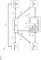
- FIG. 1is a diagram of an environment 100 in which methods, apparatuses, and systems described herein may be implemented, according to embodiments.
- the environment 100may include a user device 110, a platform 120, and a network 130.
- Devices of the environment 100may interconnect via wired connections, wireless connections, or a combination of wired and wireless connections.
- the user device 110includes one or more devices capable of receiving, generating, storing, processing, and/or providing information associated with platform 120.
- the user device 110may include a computing device (e.g. a desktop computer, a laptop computer, a tablet computer, a handheld computer, a smart speaker, a server, etc.), a mobile phone (e.g. a smart phone, a radiotelephone, etc.), a wearable device (e.g. a pair of smart glasses or a smart watch), or a similar device.
- the user device 110may receive information from and/or transmit information to the platform 120.
- the platform 120includes one or more devices as described elsewhere herein.
- the platform 120may include a cloud server or a group of cloud servers.
- the platform 120may be designed to be modular such that software components may be swapped in or out depending on a particular need. As such, the platform 120 may be easily and/or quickly reconfigured for different uses.
- the platform 120may be hosted in a cloud computing environment 122.
- the platform 120may not be cloud-based (i.e., may be implemented outside of a cloud computing environment) or may be partially cloud-based.
- the cloud computing environment 122includes an environment that hosts the platform 120.
- the cloud computing environment 122may provide computation, software, data access, storage, etc. services that do not require end-user (e.g. the user device 110) knowledge of a physical location and configuration of system(s) and/or device(s) that hosts the platform 120.
- the cloud computing environment 122may include a group of computing resources 124 (referred to collectively as “computing resources 124" and individually as “computing resource 124").
- the computing resource 124includes one or more personal computers, workstation computers, server devices, or other types of computation and/or communication devices. In some implementations, the computing resource 124 may host the platform 120.
- the cloud resourcesmay include compute instances executing in the computing resource 124, storage devices provided in the computing resource 124, data transfer devices provided by the computing resource 124, etc. In some implementations, the computing resource 124 may communicate with other computing resources 124 via wired connections, wireless connections, or a combination of wired and wireless connections.
- the computing resource 124includes a group of cloud resources, such as one or more applications (“APPs”) 124-1, one or more virtual machines (“VMs”) 124-2, virtualized storage (“VSs”) 124-3, one or more hypervisors (“HYPs”) 124-4, or the like.
- APPsapplications
- VMsvirtual machines
- VSsvirtualized storage
- HOPshypervisors
- the application 124-1includes one or more software applications that may be provided to or accessed by the user device 110 and/or the platform 120.
- the application 124-1may eliminate a need to install and execute the software applications on the user device 110.
- the application 124-1may include software associated with the platform 120 and/or any other software capable of being provided via the cloud computing environment 122.
- one application 124-1may send/receive information to/from one or more other applications 124-1, via the virtual machine 124-2.
- the virtual machine 124-2includes a software implementation of a machine (e.g. a computer) that executes programs like a physical machine.
- the virtual machine 124-2may be either a system virtual machine or a process virtual machine, depending upon use and degree of correspondence to any real machine by the virtual machine 124-2.
- a system virtual machinemay provide a complete system platform that supports execution of a complete operating system ("OS").
- a process virtual machinemay execute a single program, and may support a single process.
- the virtual machine 124-2may execute on behalf of a user (e.g. the user device 110), and may manage infrastructure of the cloud computing environment 122, such as data management, synchronization, or long-duration data transfers.
- the virtualized storage 124-3includes one or more storage systems and/or one or more devices that use virtualization techniques within the storage systems or devices of the computing resource 124.
- types of virtualizationsmay include block virtualization and file virtualization.
- Block virtualizationmay refer to abstraction (or separation) of logical storage from physical storage so that the storage system may be accessed without regard to physical storage or heterogeneous structure. The separation may permit administrators of the storage system flexibility in how the administrators manage storage for end users.
- File virtualizationmay eliminate dependencies between data accessed at a file level and a location where files are physically stored. This may enable optimization of storage use, server consolidation, and/or performance of non-disruptive file migrations.
- the hypervisor 124-4may provide hardware virtualization techniques that allow multiple operating systems (e.g. "guest operating systems") to execute concurrently on a host computer, such as the computing resource 124.
- the hypervisor 124-4may present a virtual operating platform to the guest operating systems, and may manage the execution of the guest operating systems. Multiple instances of a variety of operating systems may share virtualized hardware resources.
- the network 130includes one or more wired and/or wireless networks.
- the network 130may include a cellular network (e.g. a fifth generation (5G) network, a long-term evolution (LTE) network, a third generation (3G) network, a code division multiple access (CDMA) network, etc.), a public land mobile network (PLMN), a local area network (LAN), a wide area network (WAN), a metropolitan area network (MAN), a telephone network (e.g. the Public Switched Telephone Network (PSTN)), a private network, an ad hoc network, an intranet, the Internet, a fiber optic-based network, or the like, and/or a combination of these or other types of networks.
- 5Gfifth generation
- LTElong-term evolution
- 3Gthird generation
- CDMAcode division multiple access
- PLMNpublic land mobile network
- LANlocal area network
- WANwide area network
- MANmetropolitan area network
- PSTNPublic Switched Telephone Network
- private networke.
- the number and arrangement of devices and networks shown in FIG. 1are provided as an example. In practice, there may be additional devices and/or networks, fewer devices and/or networks, different devices and/or networks, or differently arranged devices and/or networks than those shown in FIG. 1 . Furthermore, two or more devices shown in FIG. 1 may be implemented within a single device, or a single device shown in FIG. 1 may be implemented as multiple, distributed devices. Additionally, or alternatively, a set of devices (e.g. one or more devices) of the environment 100 may perform one or more functions described as being performed by another set of devices of the environment 100.
- FIG. 2is a block diagram of example components of one or more devices of FIG. 1 .
- the device 200may correspond to the user device 110 and/or the platform 120.
- the device 200may include a bus 210, a processor 220, a memory 230, a storage component 240, an input component 250, an output component 260, and a communication interface 270.
- the bus 210includes a component that permits communication among the components of the device 200.
- the processor 220is implemented in hardware, firmware, or a combination of hardware and software.
- the processor 220is a central processing unit (CPU), a graphics processing unit (GPU), an accelerated processing unit (APU), a microprocessor, a microcontroller, a digital signal processor (DSP), a field-programmable gate array (FPGA), an application-specific integrated circuit (ASIC), or another type of processing component.
- the processor 220includes one or more processors capable of being programmed to perform a function.
- the memory 230includes a random access memory (RAM), a read only memory (ROM), and/or another type of dynamic or static storage device (e.g. a flash memory, a magnetic memory, and/or an optical memory) that stores information and/or instructions for use by the processor 220.
- RAMrandom access memory
- ROMread only memory
- optical memorye.g. a flash memory, a magnetic memory, and/or
- the storage component 240stores information and/or software related to the operation and use of the device 200.
- the storage component 240may include a hard disk (e.g. a magnetic disk, an optical disk, a magneto-optic disk, and/or a solid state disk), a compact disc (CD), a digital versatile disc (DVD), a floppy disk, a cartridge, a magnetic tape, and/or another type of non-transitory computer-readable medium, along with a corresponding drive.
- the input component 250includes a component that permits the device 200 to receive information, such as via user input (e.g. a touch screen display, a keyboard, a keypad, a mouse, a button, a switch, and/or a microphone). Additionally, or alternatively, the input component 250 may include a sensor for sensing information (e.g. a global positioning system (GPS) component, an accelerometer, a gyroscope, and/or an actuator).
- the output component 260includes a component that provides output information from the device 200 (e.g. a display, a speaker, and/or one or more light-emitting diodes (LEDs)).
- LEDslight-emitting diodes
- the communication interface 270includes a transceiver-like component (e.g. a transceiver and/or a separate receiver and transmitter) that enables the device 200 to communicate with other devices, such as via a wired connection, a wireless connection, or a combination of wired and wireless connections.
- the communication interface 270may permit the device 200 to receive information from another device and/or provide information to another device.
- the communication interface 270may include an Ethernet interface, an optical interface, a coaxial interface, an infrared interface, a radio frequency (RF) interface, a universal serial bus (USB) interface, a Wi-Fi interface, a cellular network interface, or the like.
- the device 200may perform one or more processes described herein. The device 200 may perform these processes in response to the processor 220 executing software instructions stored by a non-transitory computer-readable medium, such as the memory 230 and/or the storage component 240.
- a computer-readable mediumis defined herein as a non-transitory memory device.
- a memory deviceincludes memory space within a single physical storage device or memory space spread across multiple physical storage devices.
- Software instructionsmay be read into the memory 230 and/or the storage component 240 from another computer-readable medium or from another device via the communication interface 270. When executed, software instructions stored in the memory 230 and/or the storage component 240 may cause the processor 220 to perform one or more processes described herein. Additionally, or alternatively, hardwired circuitry may be used in place of or in combination with software instructions to perform one or more processes described herein. Thus, implementations described herein are not limited to any specific combination of hardware circuitry and software.
- the device 200may include additional components, fewer components, different components, or differently arranged components than those shown in FIG. 2 . Additionally, or alternatively, a set of components (e.g. one or more components) of the device 200 may perform one or more functions described as being performed by another set of components of the device 200.
- an NBMP system 300comprises an NBMP source 310, an NBMP workflow manager 320, a function repository 330, one or more media processing entities 350, a media source 360, and a media sink 370.
- the NBMP source 310may receive instructions from a third party entity, may communicate with the NBMP workflow manager 320 via an NBMP workflow application programming interface (API) 392, and may communicate with the function repository 330 via a function discovery API 391.
- the NBMP source 310may send a workflow description document(s) (WDD) to the NBMP workflow manager 320, and may read the function description of functions stored in the function repository 330, the functions being media processing functions stored in memory of the function repository 330 such as, for example, functions of media decoding, feature point extraction, camera parameter extraction, projection method, seam information extraction, blending, post-processing, and encoding.
- the NBMP source 310may comprise or be implemented by at least one processor and memory that stores code configured to cause the at least processor to perform the functions of the NBMP source 310.
- the NBMP source 310may request the NBMP workflow manager 320 to create workflow including tasks 352 to be performed by the one or more media processing entities 350 by sending the workflow description document, which may include several descriptors, each of which may have several parameters.
- the NBMP source 310may select functions stored in the function repository 330 and send the workflow description document to the NBMP workflow manager 320 that includes a variety of descriptors for description details such as input and output data, required functions, and requirements for the workflow.
- the workflow description documentmay include a set of task descriptions and a connection map of inputs and outputs of tasks 352 to be performed by one or more of the media processing entities 350.
- the NBMP workflow manager 320may create the workflow by instantiating the tasks based on function names and connecting the tasks in accordance with the connection map.
- the NBMP source 310may request the NBMP workflow manager 320 to create workflow by using a set of keywords.
- NBMP source 310may send the NBMP workflow manager 320 the workflow description document that may include a set of keywords that the NBMP workflow manager 320 may use to find appropriate functions stored in the function repository 330.
- the NBMP workflow manager 320may create the workflow by searching for appropriate functions using the keywords that may be specified in a Processing Descriptor of the workflow description document, and use the other descriptors in the workflow description document to provision tasks and connect them to create the workflow.
- the NBMP workflow manager 320may communicate with the function repository 330 via a function discovery API 393, which may be a same or different API from the function discovery API 391, and may communicate with one or more of the media processing entities 350 via an API 394 (e.g. an NBMP task API).
- the NBMP workflow manager 320may comprise or be implemented by at least one processor and memory that stores code configured to cause the at least processor to perform the functions of the NBMP workflow manager 320.
- the NBMP workflow manager 320may use the API 394 to setup, configure, manage, and monitor one or more tasks 352 of a workflow that is performable by the one or more media processing entities 350.
- the NBMP workflow manager 320may use the API 394 to update and destroy the tasks 352.
- the NBMP workflow manager 320may send messages, such as requests, to one or more of the media processing entities 350, wherein each message may have several descriptors, each of which have several parameters.
- the tasks 352may each include media processing functions 354 and configurations 353 for the media processing functions 354.
- the NBMP workflow manager 320may select the tasks based on the descriptions of the tasks in the workflow description document to search the function repository 330, via the function discovery API 393, to find the appropriate functions to run as tasks 352 for a current workflow. For example, the NBMP workflow manager 320 may select the tasks based on keywords provided in the workflow description document. After the appropriate functions are identified by using the keywords or the set of task descriptions that is provided by the NBMP source 310, the NBMP workflow manager 320 may configure the selected tasks in the workflow by using the API 394. For example, the NBMP workflow manager 320 may extract configuration data from information received from the NBMP source, and configure the tasks 352 based on the configuration data.
- the one or more media processing entities 350may be configured to receive media content from the media source 360, process the media content in accordance with the workflow, that includes tasks 352, created by the NBMP workflow manager 320, and output the processed media content to the media sink 370.
- the one or more media processing entities 350may each comprise or be implemented by at least one processor and memory that stores code configured to cause the at least processor to perform the functions of the media processing entities 350.
- the media source 360may include memory that stores media and may be integrated with or separate from the NBMP source 310.
- the NBMP workflow manager 320may notify the NBMP source 310 when a workflow is prepared and the media source 360 may transmit media content to the one or more of the media processing entities 350 based on the notification that the workflow is prepared.
- the media sink 370may comprise or be implemented by at least one processor and at least one display that is configured to display the media that is processed by the one or more media processing entities 350.
- messages from the NBMP Source 310e.g. a workflow description document for requesting creation of a workflow
- messages from the NBMP Source 310e.g. a workflow description document for requesting creation of a workflow
- messages (e.g. for causing the workflow to be performed) from the NBMP workflow manager 320 to the one or more media processing entities 350may include several descriptors, each of which may have several parameters.
- communication between any of the components of the NBMP system 300 using an APImay include several descriptors, each of which may have several parameters.
- Embodimentsmay provide a method for seamless switching or updating of cloud workflows during running without any interruption in data flow or missing any data. Accordingly, embodiments may add seamless continuity features to the NBMP specification.
- a workflowmay have been working for an extended period of time. Due to an increase in the volume of data, one or more tasks of the workflow may need to be split to cope with the load increase. In this case, it may be desirable that no data is lost due to switching to the new workflow.
- the current taskscan be re-used. So there the current tasks can be used in the updated workflow. In some applications, switching to a new workflow may need to happen at an exact time, for example for data collection or billing purposes.
- the NBMP Workflow API for updating workflow in the current NBMP specificationdoes not have any notion of continuity, which means that the NBMP Workflow Manager can stop the current workflow, update the workflow with the new one and start again and data may be lost during this update.
- Embodimentsmay add a continuity flag to the General Descriptor, as shown for example in Table 1 and Table 2 below.
- continuitytrue
- the NBMP Workflow managermay switch between the two workflows without losing any data.
- the switching timemay be requested to be a certain time. For example, it may be useful to know the exact time of switching for reports.
- Table 1General Descriptor Parameter Name Type Cardinality id P 1 name P 1 description P 1 rank P 0-1 mpeg-compatibility P 0-1 published-time P 0-1 priority P 0-1 execution-time P 0-1 input-ports Array of object 1 output-ports Array of object 1 is-group P 0-1 continuity P 0-1 switching_time P 0-1 state P 1
- Table 2General parameters Name Definition Unit Type Valid range id unique string in the scope of Repository/Workflow of the resource N/A string N/A name name for identifying the resource N/A string N/A description a human-readable description for the resource N/A string N/A rank The rank of Function/Function Group among Functions with the same functionality.
- N/A number unsigned integer A higher numbermeans a higher rank.
- mpeg-compatibility URNindicating the compatibility with a reference Function/Function Group defined in Annex A and B.
- URI string N/A published-time date and time of publication of this resourceAs defined by RFC333 9, section 5.6 string N/A priority priority information for the resource N/A number unsigned integer port-name unique string among all port-names of this resource defining the logic name for input or output N/A string N/A is-group value 'true' indicates containing Descriptor describes a Function Group or Task Workflow. If the value is 'true', a connection-map object may exist in this Description.
- N/A boolean N/AThe default value is 'false'.
- continuity Value 'true'indicates that this workflow update is a continuation of the previous workflow and no data may be lost during switching.
- N / A boolean N / AThe default value is false '.
- this parametermay be one of the following in a NBMP Operation's response: N/A string N/A • null • instantiated • idle • running • in-error • destroyed If this parameter is included in a request from the NBMP Source or Workflow Manager, the value of this parameter may be one of the following: • instantiated • idle
- the two new parametersmay be used with Workflow Update or Task Update.
- running a completely parallel workflowrequires a large amount of of resources, and the Cloud platform may prefer to maintain some of the tasks in the running workflow during the update.
- the Workflow Managermay identify the difference between the running workflow and the new WDD.
- the NBMP Clientcan assist in this task by providing the following information:
- each taskhas an identifier (id) in the WDD, changing a task, for example by removing and replacing it with a new task, or introducing the new task may be easily achieved:
- each workflowmay be defined by an array of connection-map objects.
- the workflow managermay compare each object in this array from the workflow update to the running workflow and identify the new or updated connection-map objects.
- an idmay be added to each connection-map object: Table 3 - Connection-Map Array Element Name Description Type Cardinality connection-id a unique identifier of this connection map.
- P 1 fromspecifies Task/Function's id and port names from which the connection is O 1 to specifies Task/Function's id and port names to which the connection is O 1
- flowcontrol-parameterscontains flow control parameters for the connection.
- O 0-1The elements of this objects may be described using flowcontrol-requirements. co-located Specifies the deployment of the 2 connected tasks. When the value is True, the 2 tasks may be deployed into the same MPE, Otherwise, the deployment is determined by the Workflow Manager based on available resources. P 0-1 The default is 'false'. other-parameters contains any other properties or parameters defined for the DAG edge, e.g. references to the Requirement Descriptor.
- N/A string N/Aos operation system N/A string N/A version version number of operation system N/A string N/A architecture hardware architecture N/A string N/A environment environment N/A string N/A patch-url URL (according to IETF RFC3986) defining the patching scheme for this image N/A string N/A scheme URL (according to IETF RFC3986) defining information object scheme or information needed for dynamic build N/A string N/A connection-id a unique string among all connection-map's ids in a workflow and its updates.
- N / A string N / A co-locatedSpecifies the deployment of the 2 connected tasks.
- N/A boolean N/AThe default is 'false'.
- idspecifies Function's id
- N/A string N/A instancespecifies identifier for one Instance of a Function. An Instance of a Function may have unique restrictions in a Function Group. This identifier may be unique for each Instance in the same Function Group.
- port-namespecifies Function's logic port name N/A string N/A
- embodimentsmay provide a method for signaling the seamless continuity of workflow operation during a workflow update, wherein no data is lost during the update, wherein the switching time is defined, and wherein in the case the requested switching time is not possible, the actual switching time is provided in the response.
- Embodimentsmay relate to a method for signaling the old and new connection in a workflow update, where each connection has a unique identifier, so that if an old connection disappears for the update, it means it is not valid anymore, and the id of a new connection appearing in the workflow update indicates it is a new connection, and the connections with the same id are considered identical and no change is required.
- Embodimentsmay relate to a method of using any of the methods described herein together to update a part of a workflow, without replacing all tasks or connections, and maintaining continuity in the data flow at the input and output of the workflow without loss of any data.
- a process 400 performed by the NBMP workflow manager 320is described below.
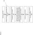
- FIG. 4is a flowchart is a flowchart of an example process 400.
- process 400may include obtaining a first network based media processing (NBMP) workflow description document (WDD) (block 410).
- NBMPnetwork based media processing
- WDDworkflow description document
- process 400may include creating a first workflow corresponding to the first WDD (block 420).
- process 400may include managing at least one media processing entity (MPE) according to the first workflow (block 430).
- MPEmedia processing entity
- process 400may include obtaining an update comprising a second WDD, wherein the second WDD includes a continuity flag indicating whether a second workflow corresponding to the second WDD is a continuation of the first workflow (block 440).
- process 400may include creating the second workflow (block 450).
- process 400may include managing the at least one MPE according to the second workflow (block 460).
- all data corresponding to the managing of the at least one MPE according to the first workflowmay be maintained during the managing of the at least one MPE according to the second workflow.
- the second WDDmay further include a syntax element indicating a time for switching from the managing of the at least one MPE according to the first workflow to the managing of the at least one MPE according to the second workflow.
- updatemay be one from among a workflow update and a task update.
- a task of the first workflowmay be represented by a first connection-map object in the first WDD, wherein the first connection-map object specifies a location of the task in a connection map corresponding to the first workflow, and at least one connection to another element in the first workflow, and wherein the first connection-map object includes a connection identifier which identifies the task.
- the taskmay be maintained in the second workflow.
- all data corresponding to execution of the task in the first workflowmay be maintained in the second workflow.
- process 800may include additional blocks, fewer blocks, different blocks, or differently arranged blocks than those depicted in FIG. 4 . Additionally, or alternatively, two or more of the blocks of process 800 may be performed in parallel.
- the proposed methodsmay be implemented by processing circuitry (e.g., one or more processors or one or more integrated circuits).
- the one or more processorsexecute a program that is stored in a non-transitory computer-readable medium to perform one or more of the proposed methods.
- At least one processor with memory storing computer code or program codemay be provided.
- the computer codemay be configured to, when executed by the at least one processor, perform any number of aspects of the present disclosure.
- computer code 500may be implemented in the NBMP system 300.
- the computer codemay be stored in memory of the NBMP workflow manager 320 and may be executed by at least one processor of the NBMP workflow manager 320.
- the computer codemay include, for example, first obtaining code 510, first deriving code 520, first managing code 530, second obtaining code 540, second deriving code 550, and second managing code 560.
- the first obtaining code 510, first deriving code 520, first managing code 530, second obtaining code 540, second deriving code 550, and second managing code 560may be configured to cause the NBMP workflow manager 320 to perform the aspects of the process described above with reference to FIG. 4 , respectively.
- Embodiments of the present disclosuremay be used separately or combined in any order. Further, each of the embodiments (and methods thereof) may be implemented by processing circuitry (e.g., one or more processors or one or more integrated circuits). In one example, the one or more processors execute a program that is stored in a non-transitory computer-readable medium.
- processing circuitrye.g., one or more processors or one or more integrated circuits.
- the one or more processorsexecute a program that is stored in a non-transitory computer-readable medium.
- the term componentis intended to be broadly construed as hardware, firmware, or a combination of hardware and software.
Landscapes
- Engineering & Computer Science (AREA)
- Computer Networks & Wireless Communication (AREA)
- Signal Processing (AREA)
- Multimedia (AREA)
- Management, Administration, Business Operations System, And Electronic Commerce (AREA)
- Information Transfer Between Computers (AREA)
- Computer And Data Communications (AREA)
Description
- Embodiments of the present disclosure are directed to Moving Picture Experts Group (MPEG) Network Based Media Processing (NBMP) and, more particularly, to managing an NBMP workflow.
- MPEG Network Based Media Processing (NBMP) project has developed a concept of processing media on cloud. The NBMP Draft International Specification shows a great potential to increase media processing efficiency, faster and lower-cost deployment of media services, and the ability to provide large scale deployment by leveraging the public, private or hybrid cloud services.
- However, while the NBMP current specification allows updating a workflow, it does not define whether the flow of data needs to be continued, or whether no data should be missed during the update.
US 8 682 939 B2 concerns a method and system for minimizing loss of critical digital data while such data is being written to a storage medium. The critical digital data is written to a digital storage medium in small blocks or segments. As each segment is transferred to the storage medium, the file allocation table is updated and the file is closed. By segmenting the files into smaller file segments, the amount of critical data lost as a result of a system failure or power loss is reduced. During playback, the file segments are dynamically assembled allowing playback of the digital data in a continuous manner.- Further features, the nature, and various advantages of the disclosed subject matter will be more apparent from the following detailed description and the accompanying drawings in which:
FIG. 1 is a diagram of an environment in which methods, apparatuses, and systems described herein may be implemented, according to embodiments.FIG. 2 is a block diagram of example components of one or more devices ofFIG. 1 .FIG. 3 is a block diagram of an NBMP system according to embodimentsFIG. 4 is a block diagram of an example of a workflow management process according to embodiments.FIG. 5 is a block diagram of an example of computer code according to embodiments.FIG. 1 is a diagram of anenvironment 100 in which methods, apparatuses, and systems described herein may be implemented, according to embodiments. As shown inFIG. 1 , theenvironment 100 may include auser device 110, aplatform 120, and anetwork 130. Devices of theenvironment 100 may interconnect via wired connections, wireless connections, or a combination of wired and wireless connections.- The
user device 110 includes one or more devices capable of receiving, generating, storing, processing, and/or providing information associated withplatform 120. For example, theuser device 110 may include a computing device (e.g. a desktop computer, a laptop computer, a tablet computer, a handheld computer, a smart speaker, a server, etc.), a mobile phone (e.g. a smart phone, a radiotelephone, etc.), a wearable device (e.g. a pair of smart glasses or a smart watch), or a similar device. In some implementations, theuser device 110 may receive information from and/or transmit information to theplatform 120. - The
platform 120 includes one or more devices as described elsewhere herein. In some implementations, theplatform 120 may include a cloud server or a group of cloud servers. In some implementations, theplatform 120 may be designed to be modular such that software components may be swapped in or out depending on a particular need. As such, theplatform 120 may be easily and/or quickly reconfigured for different uses. - In some implementations, as shown, the
platform 120 may be hosted in acloud computing environment 122. Notably, while implementations described herein describe theplatform 120 as being hosted in thecloud computing environment 122, in some implementations, theplatform 120 may not be cloud-based (i.e., may be implemented outside of a cloud computing environment) or may be partially cloud-based. - The
cloud computing environment 122 includes an environment that hosts theplatform 120. Thecloud computing environment 122 may provide computation, software, data access, storage, etc. services that do not require end-user (e.g. the user device 110) knowledge of a physical location and configuration of system(s) and/or device(s) that hosts theplatform 120. As shown, thecloud computing environment 122 may include a group of computing resources 124 (referred to collectively as "computing resources 124" and individually as "computing resource 124"). - The
computing resource 124 includes one or more personal computers, workstation computers, server devices, or other types of computation and/or communication devices. In some implementations, thecomputing resource 124 may host theplatform 120. The cloud resources may include compute instances executing in thecomputing resource 124, storage devices provided in thecomputing resource 124, data transfer devices provided by thecomputing resource 124, etc. In some implementations, thecomputing resource 124 may communicate withother computing resources 124 via wired connections, wireless connections, or a combination of wired and wireless connections. - As further shown in
FIG. 1 , thecomputing resource 124 includes a group of cloud resources, such as one or more applications ("APPs") 124-1, one or more virtual machines ("VMs") 124-2, virtualized storage ("VSs") 124-3, one or more hypervisors ("HYPs") 124-4, or the like. - The application 124-1 includes one or more software applications that may be provided to or accessed by the
user device 110 and/or theplatform 120. The application 124-1 may eliminate a need to install and execute the software applications on theuser device 110. For example, the application 124-1 may include software associated with theplatform 120 and/or any other software capable of being provided via thecloud computing environment 122. In some implementations, one application 124-1 may send/receive information to/from one or more other applications 124-1, via the virtual machine 124-2. - The virtual machine 124-2 includes a software implementation of a machine (e.g. a computer) that executes programs like a physical machine. The virtual machine 124-2 may be either a system virtual machine or a process virtual machine, depending upon use and degree of correspondence to any real machine by the virtual machine 124-2. A system virtual machine may provide a complete system platform that supports execution of a complete operating system ("OS"). A process virtual machine may execute a single program, and may support a single process. In some implementations, the virtual machine 124-2 may execute on behalf of a user (e.g. the user device 110), and may manage infrastructure of the
cloud computing environment 122, such as data management, synchronization, or long-duration data transfers. - The virtualized storage 124-3 includes one or more storage systems and/or one or more devices that use virtualization techniques within the storage systems or devices of the
computing resource 124. In some implementations, within the context of a storage system, types of virtualizations may include block virtualization and file virtualization. Block virtualization may refer to abstraction (or separation) of logical storage from physical storage so that the storage system may be accessed without regard to physical storage or heterogeneous structure. The separation may permit administrators of the storage system flexibility in how the administrators manage storage for end users. File virtualization may eliminate dependencies between data accessed at a file level and a location where files are physically stored. This may enable optimization of storage use, server consolidation, and/or performance of non-disruptive file migrations. - The hypervisor 124-4 may provide hardware virtualization techniques that allow multiple operating systems (e.g. "guest operating systems") to execute concurrently on a host computer, such as the
computing resource 124. The hypervisor 124-4 may present a virtual operating platform to the guest operating systems, and may manage the execution of the guest operating systems. Multiple instances of a variety of operating systems may share virtualized hardware resources. - The
network 130 includes one or more wired and/or wireless networks. For example, thenetwork 130 may include a cellular network (e.g. a fifth generation (5G) network, a long-term evolution (LTE) network, a third generation (3G) network, a code division multiple access (CDMA) network, etc.), a public land mobile network (PLMN), a local area network (LAN), a wide area network (WAN), a metropolitan area network (MAN), a telephone network (e.g. the Public Switched Telephone Network (PSTN)), a private network, an ad hoc network, an intranet, the Internet, a fiber optic-based network, or the like, and/or a combination of these or other types of networks. - The number and arrangement of devices and networks shown in
FIG. 1 are provided as an example. In practice, there may be additional devices and/or networks, fewer devices and/or networks, different devices and/or networks, or differently arranged devices and/or networks than those shown inFIG. 1 . Furthermore, two or more devices shown inFIG. 1 may be implemented within a single device, or a single device shown inFIG. 1 may be implemented as multiple, distributed devices. Additionally, or alternatively, a set of devices (e.g. one or more devices) of theenvironment 100 may perform one or more functions described as being performed by another set of devices of theenvironment 100. FIG. 2 is a block diagram of example components of one or more devices ofFIG. 1 . Thedevice 200 may correspond to theuser device 110 and/or theplatform 120. As shown inFIG. 2 , thedevice 200 may include a bus 210, aprocessor 220, amemory 230, astorage component 240, aninput component 250, anoutput component 260, and acommunication interface 270.- The bus 210 includes a component that permits communication among the components of the
device 200. Theprocessor 220 is implemented in hardware, firmware, or a combination of hardware and software. Theprocessor 220 is a central processing unit (CPU), a graphics processing unit (GPU), an accelerated processing unit (APU), a microprocessor, a microcontroller, a digital signal processor (DSP), a field-programmable gate array (FPGA), an application-specific integrated circuit (ASIC), or another type of processing component. In some implementations, theprocessor 220 includes one or more processors capable of being programmed to perform a function. Thememory 230 includes a random access memory (RAM), a read only memory (ROM), and/or another type of dynamic or static storage device (e.g. a flash memory, a magnetic memory, and/or an optical memory) that stores information and/or instructions for use by theprocessor 220. - The
storage component 240 stores information and/or software related to the operation and use of thedevice 200. For example, thestorage component 240 may include a hard disk (e.g. a magnetic disk, an optical disk, a magneto-optic disk, and/or a solid state disk), a compact disc (CD), a digital versatile disc (DVD), a floppy disk, a cartridge, a magnetic tape, and/or another type of non-transitory computer-readable medium, along with a corresponding drive. - The
input component 250 includes a component that permits thedevice 200 to receive information, such as via user input (e.g. a touch screen display, a keyboard, a keypad, a mouse, a button, a switch, and/or a microphone). Additionally, or alternatively, theinput component 250 may include a sensor for sensing information (e.g. a global positioning system (GPS) component, an accelerometer, a gyroscope, and/or an actuator). Theoutput component 260 includes a component that provides output information from the device 200 (e.g. a display, a speaker, and/or one or more light-emitting diodes (LEDs)). - The
communication interface 270 includes a transceiver-like component (e.g. a transceiver and/or a separate receiver and transmitter) that enables thedevice 200 to communicate with other devices, such as via a wired connection, a wireless connection, or a combination of wired and wireless connections. Thecommunication interface 270 may permit thedevice 200 to receive information from another device and/or provide information to another device. For example, thecommunication interface 270 may include an Ethernet interface, an optical interface, a coaxial interface, an infrared interface, a radio frequency (RF) interface, a universal serial bus (USB) interface, a Wi-Fi interface, a cellular network interface, or the like. - The
device 200 may perform one or more processes described herein. Thedevice 200 may perform these processes in response to theprocessor 220 executing software instructions stored by a non-transitory computer-readable medium, such as thememory 230 and/or thestorage component 240. A computer-readable medium is defined herein as a non-transitory memory device. A memory device includes memory space within a single physical storage device or memory space spread across multiple physical storage devices. - Software instructions may be read into the
memory 230 and/or thestorage component 240 from another computer-readable medium or from another device via thecommunication interface 270. When executed, software instructions stored in thememory 230 and/or thestorage component 240 may cause theprocessor 220 to perform one or more processes described herein. Additionally, or alternatively, hardwired circuitry may be used in place of or in combination with software instructions to perform one or more processes described herein. Thus, implementations described herein are not limited to any specific combination of hardware circuitry and software. - The number and arrangement of components shown in
FIG. 2 are provided as an example. In practice, thedevice 200 may include additional components, fewer components, different components, or differently arranged components than those shown inFIG. 2 . Additionally, or alternatively, a set of components (e.g. one or more components) of thedevice 200 may perform one or more functions described as being performed by another set of components of thedevice 200. - In an embodiment of the present disclosure, an
NBMP system 300 is provided. With reference toFIG. 3 , theNBMP system 300 comprises anNBMP source 310, anNBMP workflow manager 320, afunction repository 330, one or moremedia processing entities 350, amedia source 360, and amedia sink 370. - The
NBMP source 310 may receive instructions from a third party entity, may communicate with theNBMP workflow manager 320 via an NBMP workflow application programming interface (API) 392, and may communicate with thefunction repository 330 via afunction discovery API 391. For example, theNBMP source 310 may send a workflow description document(s) (WDD) to theNBMP workflow manager 320, and may read the function description of functions stored in thefunction repository 330, the functions being media processing functions stored in memory of thefunction repository 330 such as, for example, functions of media decoding, feature point extraction, camera parameter extraction, projection method, seam information extraction, blending, post-processing, and encoding. TheNBMP source 310 may comprise or be implemented by at least one processor and memory that stores code configured to cause the at least processor to perform the functions of theNBMP source 310. - The
NBMP source 310 may request theNBMP workflow manager 320 to createworkflow including tasks 352 to be performed by the one or moremedia processing entities 350 by sending the workflow description document, which may include several descriptors, each of which may have several parameters. - For example, the
NBMP source 310 may select functions stored in thefunction repository 330 and send the workflow description document to theNBMP workflow manager 320 that includes a variety of descriptors for description details such as input and output data, required functions, and requirements for the workflow. The workflow description document may include a set of task descriptions and a connection map of inputs and outputs oftasks 352 to be performed by one or more of themedia processing entities 350. When theNBMP workflow manager 320 receives such information from theNBMP source 310, theNBMP workflow manager 320 may create the workflow by instantiating the tasks based on function names and connecting the tasks in accordance with the connection map. - Alternatively or additionally, the
NBMP source 310 may request theNBMP workflow manager 320 to create workflow by using a set of keywords. For example,NBMP source 310 may send theNBMP workflow manager 320 the workflow description document that may include a set of keywords that theNBMP workflow manager 320 may use to find appropriate functions stored in thefunction repository 330. When theNBMP workflow manager 320 receives such information from theNBMP source 310, theNBMP workflow manager 320 may create the workflow by searching for appropriate functions using the keywords that may be specified in a Processing Descriptor of the workflow description document, and use the other descriptors in the workflow description document to provision tasks and connect them to create the workflow. - The
NBMP workflow manager 320 may communicate with thefunction repository 330 via afunction discovery API 393, which may be a same or different API from thefunction discovery API 391, and may communicate with one or more of themedia processing entities 350 via an API 394 (e.g. an NBMP task API). TheNBMP workflow manager 320 may comprise or be implemented by at least one processor and memory that stores code configured to cause the at least processor to perform the functions of theNBMP workflow manager 320. - The
NBMP workflow manager 320 may use theAPI 394 to setup, configure, manage, and monitor one ormore tasks 352 of a workflow that is performable by the one or moremedia processing entities 350. In an embodiment, theNBMP workflow manager 320 may use theAPI 394 to update and destroy thetasks 352. In order to configure, manage, and monitortasks 352 of the workflow, theNBMP workflow manager 320 may send messages, such as requests, to one or more of themedia processing entities 350, wherein each message may have several descriptors, each of which have several parameters. Thetasks 352 may each include media processing functions 354 andconfigurations 353 for the media processing functions 354. - In an embodiment, after receiving a workflow description document from the
NBMP source 310 that does not include a list of the tasks (e.g. includes a list of keywords instead of a list of tasks), theNBMP workflow manager 320 may select the tasks based on the descriptions of the tasks in the workflow description document to search thefunction repository 330, via thefunction discovery API 393, to find the appropriate functions to run astasks 352 for a current workflow. For example, theNBMP workflow manager 320 may select the tasks based on keywords provided in the workflow description document. After the appropriate functions are identified by using the keywords or the set of task descriptions that is provided by theNBMP source 310, theNBMP workflow manager 320 may configure the selected tasks in the workflow by using theAPI 394. For example, theNBMP workflow manager 320 may extract configuration data from information received from the NBMP source, and configure thetasks 352 based on the configuration data. - The one or more
media processing entities 350 may be configured to receive media content from themedia source 360, process the media content in accordance with the workflow, that includestasks 352, created by theNBMP workflow manager 320, and output the processed media content to themedia sink 370. The one or moremedia processing entities 350 may each comprise or be implemented by at least one processor and memory that stores code configured to cause the at least processor to perform the functions of themedia processing entities 350. - The
media source 360 may include memory that stores media and may be integrated with or separate from theNBMP source 310. In an embodiment, theNBMP workflow manager 320 may notify theNBMP source 310 when a workflow is prepared and themedia source 360 may transmit media content to the one or more of themedia processing entities 350 based on the notification that the workflow is prepared. - The media sink 370 may comprise or be implemented by at least one processor and at least one display that is configured to display the media that is processed by the one or more
media processing entities 350. - As discussed above, messages from the NBMP Source 310 (e.g. a workflow description document for requesting creation of a workflow) to the
NBMP workflow manager 320, and messages (e.g. for causing the workflow to be performed) from theNBMP workflow manager 320 to the one or moremedia processing entities 350 may include several descriptors, each of which may have several parameters. In embodiments, communication between any of the components of theNBMP system 300 using an API may include several descriptors, each of which may have several parameters. - Embodiments may provide a method for seamless switching or updating of cloud workflows during running without any interruption in data flow or missing any data. Accordingly, embodiments may add seamless continuity features to the NBMP specification.
- During an NBMP-related process, a workflow may have been working for an extended period of time. Due to an increase in the volume of data, one or more tasks of the workflow may need to be split to cope with the load increase. In this case, it may be desirable that no data is lost due to switching to the new workflow.
- In some deployments, the current tasks can be re-used. So there the current tasks can be used in the updated workflow. In some applications, switching to a new workflow may need to happen at an exact time, for example for data collection or billing purposes.
- The NBMP Workflow API for updating workflow in the current NBMP specification does not have any notion of continuity, which means that the NBMP Workflow Manager can stop the current workflow, update the workflow with the new one and start again and data may be lost during this update.
- Embodiments may add a continuity flag to the General Descriptor, as shown for example in Table 1 and Table 2 below. In the case of continuity = true, the NBMP Workflow manager may switch between the two workflows without losing any data. Furthermore, the switching time may be requested to be a certain time. For example, it may be useful to know the exact time of switching for reports.
Table 1 - General Descriptor Parameter Name Type Cardinality id P 1 name P 1 description P 1 rank P 0-1 mpeg-compatibility P 0-1 published-time P 0-1 priority P 0-1 execution-time P 0-1 input-ports Array of object 1 output-ports Array of object 1 is-group P 0-1 continuity P 0-1 switching_time P 0-1 state P 1 Table 2 - General parameters Name Definition Unit Type Valid range id unique string in the scope of Repository/Workflow of the resource N/A string N/A name name for identifying the resource N/A string N/A description a human-readable description for the resource N/A string N/A rank The rank of Function/Function Group among Functions with the same functionality. N/A number unsigned integer A higher number means a higher rank. mpeg-compatibility URN indicating the compatibility with a reference Function/Function Group defined in Annex A and B. URI string N/A published-time date and time of publication of this resource As defined by RFC333 9, section 5.6 string N/A priority priority information for the resource N/A number unsigned integer port-name unique string among all port-names of this resource defining the logic name for input or output N/A string N/A is-group value 'true' indicates containing Descriptor describes a Function Group or Task Workflow. If the value is 'true', a connection-map object may exist in this Description. N/A boolean N/A The default value is 'false'. continuity Value 'true' indicates that this workflow update is a continuation of the previous workflow and no data may be lost during switching. N/A boolean N/A The default value is false'. switching_time Switching time of the workflow to its update. If this value is in the past, then the switch should happen immediately and is updated with the exact switching time. As defined by RFC333 9,section 5.6 string N/A If a lossless transition can not occur at this time, then the switch should happen at the first possible time and is updated with the exact switching time. The value is ignored is 'continuity' is 'false' state current state of the resource in its lifecycle The value of this parameter may be one of the following in a NBMP Operation's response: N/A string N/A • null • instantiated • idle • running • in-error • destroyed If this parameter is included in a request from the NBMP Source or Workflow Manager, the value of this parameter may be one of the following: • instantiated • idle - In tables herein, additions to the NBMP specification according to embodiments may be indicated byitalics.
- In embodiments, the two new parameters may be used with Workflow Update or Task Update.
- In some cases, running a completely parallel workflow requires a large amount of of resources, and the Cloud platform may prefer to maintain some of the tasks in the running workflow during the update.
- Because the NBMP Client provides the new WDD, the Workflow Manager may identify the difference between the running workflow and the new WDD.
- The NBMP Client can assist in this task by providing the following information:
- 1. The list of tasks that are changed.
- 2. The list of connections that are changed.
- Because each task has an identifier (id) in the WDD, changing a task, for example by removing and replacing it with a new task, or introducing the new task may be easily achieved:
- 1. Every existing task has an id in the running workflow.
- 2. The location of a task in the running workflow is identified with the value of 'instance' in the connection map.
- 3. Any new task in the workflow update doesn't have 'instance' set.
- Considering the above, it may be easy for the NBMP Workflow Manager to identify which tasks/function instances in the updated workflow are new and which ones are the old ones.
- As for providing the list of connections, each workflow may be defined by an array of connection-map objects. The workflow manager may compare each object in this array from the workflow update to the running workflow and identify the new or updated connection-map objects. However, to simplify the process, in embodiments an id may be added to each connection-map object:
Table 3 -Connection-Map Array Element Name Description Type Cardinality connection-id a unique identifier of this connection map. During a WDD update, any connection-map element which has the identical connection-id to the existing WDD, is considered the same and requires no update. If the WDD update is continuous (using the 'continuity' flag), this connection may remain working with no interruption in its data flow. P 1 from specifies Task/Function's id and port names from which the connection is O 1 to specifies Task/Function's id and port names to which the connection is O 1 flowcontrol-parameters contains flow control parameters for the connection. O 0-1 The elements of this objects may be described using flowcontrol-requirements. co-located Specifies the deployment of the 2 connected tasks. When the value is True, the 2 tasks may be deployed into the same MPE, Otherwise, the deployment is determined by the Workflow Manager based on available resources. P 0-1 The default is 'false'. other-parameters contains any other properties or parameters defined for the DAG edge, e.g. references to the Requirement Descriptor. The elements of this objects may be described using generic parameter representation of subclause 9.20.1.1 O 0-1 Table 4 - Processing Parameters Name Definition Unit Type Valid range keywords list of keywords that can be used to execute a search in the Function Repository N/A array of string N/A start-time resource's start time As defined by RFC333 9, section 5.6 string N/A is-dynamic flag indicating whether the image is static or dynamic. A value of 'true' indicates the image is built dynamically. N/A boolean N/A The default value is 'false' (static image). url pointer to the resource implementation, according to IETF RFC3986 N/A string N/A os operation system N/A string N/A version version number of operation system N/A string N/A architecture hardware architecture N/A string N/A environment environment N/A string N/A patch-url URL (according to IETF RFC3986) defining the patching scheme for this image N/A string N/A scheme URL (according to IETF RFC3986) defining information object scheme or information needed for dynamic build N/A string N/A connection-id a unique string among all connection-map's ids in a workflow and its updates. N/A string N/A co-located Specifies the deployment of the 2 connected tasks. When the value is True, the 2 tasks may be deployed into the same MPE, Otherwise, the deployment is determined by the Workflow Manager based on available resources. N/A boolean N/A The default is 'false'. id specifies Function's id N/A string N/A instance specifies identifier for one Instance of a Function. An Instance of a Function may have unique restrictions in a Function Group. This identifier may be unique for each Instance in the same Function Group. N/A string N/A Note: If a Function is used more than once in one Function Group with identical restrictions, these restrictions can be defined by one Instance of that Function. port-name specifies Function's logic port name N/A string N/A - As discussed above, in tables herein, additions to the NBMP specification according to embodiments may be indicated byitalics.
- Accordingly, embodiments may provide a method for signaling the seamless continuity of workflow operation during a workflow update, wherein no data is lost during the update, wherein the switching time is defined, and wherein in the case the requested switching time is not possible, the actual switching time is provided in the response.
- Embodiments may relate to a method for signaling the old and new connection in a workflow update, where each connection has a unique identifier, so that if an old connection disappears for the update, it means it is not valid anymore, and the id of a new connection appearing in the workflow update indicates it is a new connection, and the connections with the same id are considered identical and no change is required.
- Embodiments may relate to a method of using any of the methods described herein together to update a part of a workflow, without replacing all tasks or connections, and maintaining continuity in the data flow at the input and output of the workflow without loss of any data.
- With reference to
FIGs. 3 and4 , aprocess 400 performed by theNBMP workflow manager 320 is described below. FIG. 4 is a flowchart is a flowchart of anexample process 400.- As shown in
FIG. 4 ,process 400 may include obtaining a first network based media processing (NBMP) workflow description document (WDD) (block 410). - As further shown in
FIG. 4 ,process 400 may include creating a first workflow corresponding to the first WDD (block 420). - As further shown in
FIG. 4 ,process 400 may include managing at least one media processing entity (MPE) according to the first workflow (block 430). - As further shown in
FIG. 4 ,process 400 may include obtaining an update comprising a second WDD, wherein the second WDD includes a continuity flag indicating whether a second workflow corresponding to the second WDD is a continuation of the first workflow (block 440). - As further shown in
FIG. 4 ,process 400 may include creating the second workflow (block 450). - As further shown in
FIG. 4 ,process 400 may include managing the at least one MPE according to the second workflow (block 460). - In embodiments, based on the continuity flag indicating that the second workflow is the continuation of the first workflow, all data corresponding to the managing of the at least one MPE according to the first workflow may be maintained during the managing of the at least one MPE according to the second workflow.
- In embodiments, the second WDD may further include a syntax element indicating a time for switching from the managing of the at least one MPE according to the first workflow to the managing of the at least one MPE according to the second workflow.
- In embodiments, update may be one from among a workflow update and a task update.
- In embodiments, a task of the first workflow may be represented by a first connection-map object in the first WDD, wherein the first connection-map object specifies a location of the task in a connection map corresponding to the first workflow, and at least one connection to another element in the first workflow, and wherein the first connection-map object includes a connection identifier which identifies the task.
- In embodiments, based on the connection identifier being included in a second connection-map object in the second WDD, the task may be maintained in the second workflow.
- In embodiments, based on the continuity flag indicating that the second workflow is the continuation of the first workflow, all data corresponding to execution of the task in the first workflow may be maintained in the second workflow.
- Although
FIG. 4 shows example blocks ofprocess 400, in some implementations, process 800 may include additional blocks, fewer blocks, different blocks, or differently arranged blocks than those depicted inFIG. 4 . Additionally, or alternatively, two or more of the blocks of process 800 may be performed in parallel. - Further, the proposed methods may be implemented by processing circuitry (e.g., one or more processors or one or more integrated circuits). In one example, the one or more processors execute a program that is stored in a non-transitory computer-readable medium to perform one or more of the proposed methods.
- According to embodiments of the present disclosure, at least one processor with memory storing computer code or program code may be provided. The computer code may be configured to, when executed by the at least one processor, perform any number of aspects of the present disclosure.
- For example, with reference to
FIG. 5 ,computer code 500 may be implemented in theNBMP system 300. For example, the computer code may be stored in memory of theNBMP workflow manager 320 and may be executed by at least one processor of theNBMP workflow manager 320. The computer code may include, for example, first obtainingcode 510,first deriving code 520, first managingcode 530, second obtainingcode 540,second deriving code 550, and second managingcode 560. - In embodiments, the first obtaining
code 510,first deriving code 520, first managingcode 530, second obtainingcode 540,second deriving code 550, and second managingcode 560 may be configured to cause theNBMP workflow manager 320 to perform the aspects of the process described above with reference toFIG. 4 , respectively. - Embodiments of the present disclosure may be used separately or combined in any order. Further, each of the embodiments (and methods thereof) may be implemented by processing circuitry (e.g., one or more processors or one or more integrated circuits). In one example, the one or more processors execute a program that is stored in a non-transitory computer-readable medium.
- The foregoing disclosure provides illustration and description, but is not intended to be exhaustive or to limit the implementations to the precise form disclosed. Modifications and variations are possible in light of the above disclosure or may be acquired from practice of the implementations.
- As used herein, the term component is intended to be broadly construed as hardware, firmware, or a combination of hardware and software.
Claims (15)
- A method performed by at least one processor of a workflow manager of a media system comprising:obtaining (410) a first network based media processing, NBMP, workflow description document, WDD;creating (420) a first workflow corresponding to the first NBMP WDD;managing (430) at least one media processing entity, MPE, according to the first workflow;obtaining (440) an update comprising a second NBMP WDD, wherein the second NBMP WDD includes a continuity flag indicating whether a second workflow corresponding to the second NBMP WDD is a continuation of the first workflow;creating (450) the second workflow based on the second NBMP WDD; andin response to creating the second workflow, managing (460) the at least one MPE according to the second workflow.
- The method of claim 1, wherein based on the continuity flag indicating that the second workflow is the continuation of the first workflow, all data corresponding to the managing of the at least one MPE according to the first workflow is maintained during the managing of the at least one MPE according to the second workflow.
- The method of claim 1 or 2, wherein the second NBMP WDD further comprises a syntax element indicating a time for switching from the managing of the at least one MPE according to the first workflow to the managing of the at least one MPE according to the second workflow.
- The method of any one of claims 1-3, wherein the update is one from among a workflow update and a task update.
- The method of any one of claims 1-4, wherein a task of the first workflow is represented by a first connection-map object in the first NBMP WDD,wherein the first connection-map object specifies a location of the task in a connection map corresponding to the first workflow, and at least one connection to another element in the first workflow, andwherein the first connection-map object includes a connection identifier which identifies the task.
- The method of claim 5, wherein based on the connection identifier being included in a second connection-map object in the second NBMP WDD, the task is maintained in the second workflow.
- The method of claim 6, wherein based on the continuity flag indicating that the second workflow is the continuation of the first workflow, all data corresponding to execution of the task in the first workflow is maintained in the second workflow.
- A workflow manager of a media system, the workflow manager comprising:at least one memory storing program code; andat least one processor configured to read the program code and operate as instructed by the program code, the program code including:first obtaining code configured to cause the at least one processor to obtain a first network based media processing, NBMP, workflow description document, WDD;first creating code configured to cause the at least one processor to create a first workflow corresponding to the first NBMP WDD;first managing code configured to cause the at least one processor to manage at least one media processing entity, MPE, according to the first workflow;second obtaining code configured to cause the at least one processor to obtain an update comprising a second NBMP WDD, wherein the second NBMP WDD includes a continuity flag indicating whether a second workflow corresponding to the second NBMP WDD is a continuation of the first workflow;second creating code configured to cause the at least one processor to create the second workflow based on the second NBMP WDD; andsecond managing code configured to cause the at least one processor to manage the at least one MPE according to the second workflow.
- The workflow manager of claim 8, wherein based on the continuity flag indicating that the second workflow is the continuation of the first workflow, all data corresponding to the managing of the at least one MPE according to the first workflow is maintained during the managing of the at least one MPE according to the second workflow.
- The workflow manager of claim 8 or 9, wherein the second NBMP WDD further comprises a syntax element indicating a time for switching from the managing of the at least one MPE according to the first workflow to the managing of the at least one MPE according to the second workflow.
- The workflow manager of any one of claims 8-10, wherein the update is one from among a workflow update and a task update.
- The workflow manager of any one of claims 8-10, wherein a task of the first workflow is represented by a first connection-map object in the first NBMP WDD,wherein the first connection-map object specifies a location of the task in a connection map corresponding to the first workflow, and at least one connection to another element in the first workflow, andwherein the first connection-map object includes a connection identifier which identifies the task.
- The workflow manager of claim 12, wherein based on the connection identifier being included in a second connection-map object in the second NBMP WDD, the task is maintained in the second workflow.
- The workflow manager of claim 13, wherein based on the continuity flag indicating that the second workflow is the continuation of the first workflow, all data corresponding to execution of the task in the first workflow is maintained in the second workflow.
- A non-transitory computer-readable medium storing computer code that is configured to, when executed by at least one processor that implements a workflow manager of a media system, cause the at least one processor to perform the method of any one of claims 1-7.
Applications Claiming Priority (3)
| Application Number | Priority Date | Filing Date | Title |
|---|---|---|---|
| US202163176761P | 2021-04-19 | 2021-04-19 | |
| US17/704,760US12069125B2 (en) | 2021-04-19 | 2022-03-25 | Method for switching workflow or updating workflow with continuity and no interruption in dataflow |
| PCT/US2022/022106WO2022225650A2 (en) | 2021-04-19 | 2022-03-28 | Method for switching workflow or updating workflow with continuity and no interruption in dataflow |
Publications (3)
| Publication Number | Publication Date |
|---|---|
| EP4118649A2 EP4118649A2 (en) | 2023-01-18 |
| EP4118649A4 EP4118649A4 (en) | 2023-02-15 |
| EP4118649B1true EP4118649B1 (en) | 2024-05-29 |
Family
ID=83602949
Family Applications (1)
| Application Number | Title | Priority Date | Filing Date |
|---|---|---|---|
| EP22782814.2AActiveEP4118649B1 (en) | 2021-04-19 | 2022-03-28 | Method for switching workflow or updating workflow with continuity and no interruption in dataflow |
Country Status (6)
| Country | Link |
|---|---|
| US (1) | US12069125B2 (en) |
| EP (1) | EP4118649B1 (en) |
| JP (1) | JP7515614B2 (en) |
| KR (1) | KR102814356B1 (en) |
| CN (1) | CN115668373B (en) |
| WO (1) | WO2022225650A2 (en) |
Families Citing this family (1)
| Publication number | Priority date | Publication date | Assignee | Title |
|---|---|---|---|---|
| US11297121B2 (en)* | 2020-04-07 | 2022-04-05 | Tencent America LLC | Split rendering using network based media processing workflow |
Family Cites Families (11)
| Publication number | Priority date | Publication date | Assignee | Title |
|---|---|---|---|---|
| US8682939B2 (en) | 2002-05-22 | 2014-03-25 | Teac Aerospace Technologies, Inc. | Video and audio recording using file segmentation to preserve the integrity of critical data |
| FR2972320B1 (en) | 2011-03-03 | 2013-10-18 | Ass Pour La Rech Et Le Dev De Methodes Et Processus Ind Armines | LOSS-FREE DATA CODING FOR BIDIRECTIONAL COMMUNICATION IN A COLLABORATIVE SESSION OF MULTIMEDIA CONTENT EXCHANGE |
| US10740093B2 (en) | 2016-09-01 | 2020-08-11 | Dropbox, Inc. | Advanced packaging techniques for improving work flows |
| EP3510460A4 (en) | 2016-09-09 | 2020-01-15 | Dematic Corp. | COMMUNICATION SYSTEM FOR THE OPERATION AND MANAGEMENT OF WORKFLOWS AND THE INTEGRATION OF SEVERAL DEVICES USING DIFFERENT OPERATING PLATFORMS |
| WO2018213481A1 (en) | 2017-05-16 | 2018-11-22 | Sportscastr.Live Llc | Systems, apparatus, and methods for scalable low-latency viewing of integrated broadcast commentary and event video streams of live events, and synchronization of event information with viewed streams via multiple internet channels |
| US11363087B2 (en)* | 2018-05-24 | 2022-06-14 | Disney Enterprises, Inc. | Leveraging microservices to orchestrate media workflows in the cloud |
| US11381885B2 (en)* | 2018-12-03 | 2022-07-05 | Samsung Electronics Co., Ltd. | Method and device for managing processing of media content, and computer-readable recording medium |
| JP2022051975A (en) | 2019-02-12 | 2022-04-04 | ソニーグループ株式会社 | Information processing device and information processing method |
| CN111835549B (en)* | 2019-04-23 | 2023-09-05 | 腾讯美国有限责任公司 | Method, apparatus, computer device and medium for processing media content |
| US11256546B2 (en)* | 2019-07-02 | 2022-02-22 | Nokia Technologies Oy | Methods, apparatuses and computer readable mediums for network based media processing |
| US12293218B2 (en) | 2019-09-28 | 2025-05-06 | Tencent America LLC | Method and apparatus for a step-enabled workflow |
- 2022
- 2022-03-25USUS17/704,760patent/US12069125B2/enactiveActive
- 2022-03-28CNCN202280003940.9Apatent/CN115668373B/enactiveActive
- 2022-03-28WOPCT/US2022/022106patent/WO2022225650A2/ennot_activeCeased
- 2022-03-28KRKR1020227037230Apatent/KR102814356B1/enactiveActive
- 2022-03-28EPEP22782814.2Apatent/EP4118649B1/enactiveActive
- 2022-03-28JPJP2022563074Apatent/JP7515614B2/enactiveActive
Also Published As
| Publication number | Publication date |
|---|---|
| WO2022225650A2 (en) | 2022-10-27 |
| JP7515614B2 (en) | 2024-07-12 |
| EP4118649A4 (en) | 2023-02-15 |
| KR20220160050A (en) | 2022-12-05 |
| WO2022225650A3 (en) | 2022-12-01 |
| KR102814356B1 (en) | 2025-05-30 |
| JP2023525661A (en) | 2023-06-19 |
| CN115668373B (en) | 2024-11-15 |
| US12069125B2 (en) | 2024-08-20 |
| CN115668373A (en) | 2023-01-31 |
| US20220337530A1 (en) | 2022-10-20 |
| EP4118649A2 (en) | 2023-01-18 |
Similar Documents
| Publication | Publication Date | Title |
|---|---|---|
| US11606402B2 (en) | Split rendering using network based media processing workflow | |
| EP3939235B1 (en) | Method and apparatus for envelope descriptor in moving picture experts group network based media processing | |
| US11356534B2 (en) | Function repository selection mode and signaling for cloud based processing | |
| US11743307B2 (en) | Nonessential input, output and task signaling in workflows on cloud platforms | |
| US11520630B2 (en) | Extensible schemes and scheme signaling for cloud based processing | |
| US12045650B2 (en) | Extensible schemes and scheme signaling for cloud based processing | |
| US20230109209A1 (en) | Method and apparatus for signaling net-zero workflow modifications on cloud platforms | |
| EP4118649B1 (en) | Method for switching workflow or updating workflow with continuity and no interruption in dataflow | |
| US20210320987A1 (en) | Task proximity for cloud services | |
| US20240022487A1 (en) | Methods for monitoring, reporting and notification of cloud platform's system variables and events | |
| US11539776B2 (en) | Method for signaling protocol characteristics for cloud workflow inputs and outputs | |
| US11838390B2 (en) | Function repository selection mode and signaling for cloud based processing | |
| US12206749B2 (en) | Deployment of workflow tasks with fixed preconfigured parameters in cloud-based media applications | |
| WO2021207027A1 (en) | Task proximity for cloud services | |
| HK40071736A (en) | Method for managing network based media processing workflow, workflow manager, computer device and computer readable medium |
Legal Events
| Date | Code | Title | Description |
|---|---|---|---|
| STAA | Information on the status of an ep patent application or granted ep patent | Free format text:STATUS: UNKNOWN | |
| STAA | Information on the status of an ep patent application or granted ep patent | Free format text:STATUS: THE INTERNATIONAL PUBLICATION HAS BEEN MADE | |
| PUAI | Public reference made under article 153(3) epc to a published international application that has entered the european phase | Free format text:ORIGINAL CODE: 0009012 | |
| STAA | Information on the status of an ep patent application or granted ep patent | Free format text:STATUS: REQUEST FOR EXAMINATION WAS MADE | |
| 17P | Request for examination filed | Effective date:20221012 | |
| AK | Designated contracting states | Kind code of ref document:A2 Designated state(s):AL AT BE BG CH CY CZ DE DK EE ES FI FR GB GR HR HU IE IS IT LI LT LU LV MC MK MT NL NO PL PT RO RS SE SI SK SM TR | |
| A4 | Supplementary search report drawn up and despatched | Effective date:20230118 | |
| RIC1 | Information provided on ipc code assigned before grant | Ipc:H04L 47/80 20220101ALI20230112BHEP Ipc:H04L 67/02 20220101ALI20230112BHEP Ipc:H04N 21/63 20110101ALI20230112BHEP Ipc:G11B 20/10 19850101ALI20230112BHEP Ipc:G11B 27/031 19900101AFI20230112BHEP | |
| GRAP | Despatch of communication of intention to grant a patent | Free format text:ORIGINAL CODE: EPIDOSNIGR1 | |
| STAA | Information on the status of an ep patent application or granted ep patent | Free format text:STATUS: GRANT OF PATENT IS INTENDED | |
| DAV | Request for validation of the european patent (deleted) | ||
| DAX | Request for extension of the european patent (deleted) | ||
| INTG | Intention to grant announced | Effective date:20240228 | |
| GRAS | Grant fee paid | Free format text:ORIGINAL CODE: EPIDOSNIGR3 | |
| GRAA | (expected) grant | Free format text:ORIGINAL CODE: 0009210 | |
| STAA | Information on the status of an ep patent application or granted ep patent | Free format text:STATUS: THE PATENT HAS BEEN GRANTED | |
| AK | Designated contracting states | Kind code of ref document:B1 Designated state(s):AL AT BE BG CH CY CZ DE DK EE ES FI FR GB GR HR HU IE IS IT LI LT LU LV MC MK MT NL NO PL PT RO RS SE SI SK SM TR | |
| REG | Reference to a national code | Ref country code:CH Ref legal event code:EP | |
| REG | Reference to a national code | Ref country code:IE Ref legal event code:FG4D | |
| REG | Reference to a national code | Ref country code:DE Ref legal event code:R096 Ref document number:602022003712 Country of ref document:DE | |
| REG | Reference to a national code | Ref country code:LT Ref legal event code:MG9D | |
| REG | Reference to a national code | Ref country code:NL Ref legal event code:MP Effective date:20240529 | |
| PG25 | Lapsed in a contracting state [announced via postgrant information from national office to epo] | Ref country code:IS Free format text:LAPSE BECAUSE OF FAILURE TO SUBMIT A TRANSLATION OF THE DESCRIPTION OR TO PAY THE FEE WITHIN THE PRESCRIBED TIME-LIMIT Effective date:20240929 | |
| PG25 | Lapsed in a contracting state [announced via postgrant information from national office to epo] | Ref country code:BG Free format text:LAPSE BECAUSE OF FAILURE TO SUBMIT A TRANSLATION OF THE DESCRIPTION OR TO PAY THE FEE WITHIN THE PRESCRIBED TIME-LIMIT Effective date:20240529 | |
| PG25 | Lapsed in a contracting state [announced via postgrant information from national office to epo] | Ref country code:HR Free format text:LAPSE BECAUSE OF FAILURE TO SUBMIT A TRANSLATION OF THE DESCRIPTION OR TO PAY THE FEE WITHIN THE PRESCRIBED TIME-LIMIT Effective date:20240529 Ref country code:FI Free format text:LAPSE BECAUSE OF FAILURE TO SUBMIT A TRANSLATION OF THE DESCRIPTION OR TO PAY THE FEE WITHIN THE PRESCRIBED TIME-LIMIT Effective date:20240529 | |
| PG25 | Lapsed in a contracting state [announced via postgrant information from national office to epo] | Ref country code:GR Free format text:LAPSE BECAUSE OF FAILURE TO SUBMIT A TRANSLATION OF THE DESCRIPTION OR TO PAY THE FEE WITHIN THE PRESCRIBED TIME-LIMIT Effective date:20240830 | |
| REG | Reference to a national code | Ref country code:AT Ref legal event code:MK05 Ref document number:1691335 Country of ref document:AT Kind code of ref document:T Effective date:20240529 | |
| PG25 | Lapsed in a contracting state [announced via postgrant information from national office to epo] | Ref country code:ES Free format text:LAPSE BECAUSE OF FAILURE TO SUBMIT A TRANSLATION OF THE DESCRIPTION OR TO PAY THE FEE WITHIN THE PRESCRIBED TIME-LIMIT Effective date:20240529 | |
| PG25 | Lapsed in a contracting state [announced via postgrant information from national office to epo] | Ref country code:AT Free format text:LAPSE BECAUSE OF FAILURE TO SUBMIT A TRANSLATION OF THE DESCRIPTION OR TO PAY THE FEE WITHIN THE PRESCRIBED TIME-LIMIT Effective date:20240529 | |
| PG25 | Lapsed in a contracting state [announced via postgrant information from national office to epo] | Ref country code:PL Free format text:LAPSE BECAUSE OF FAILURE TO SUBMIT A TRANSLATION OF THE DESCRIPTION OR TO PAY THE FEE WITHIN THE PRESCRIBED TIME-LIMIT Effective date:20240529 | |
| PG25 | Lapsed in a contracting state [announced via postgrant information from national office to epo] | Ref country code:LV Free format text:LAPSE BECAUSE OF FAILURE TO SUBMIT A TRANSLATION OF THE DESCRIPTION OR TO PAY THE FEE WITHIN THE PRESCRIBED TIME-LIMIT Effective date:20240529 | |
| PG25 | Lapsed in a contracting state [announced via postgrant information from national office to epo] | Ref country code:PL Free format text:LAPSE BECAUSE OF FAILURE TO SUBMIT A TRANSLATION OF THE DESCRIPTION OR TO PAY THE FEE WITHIN THE PRESCRIBED TIME-LIMIT Effective date:20240529 Ref country code:NO Free format text:LAPSE BECAUSE OF FAILURE TO SUBMIT A TRANSLATION OF THE DESCRIPTION OR TO PAY THE FEE WITHIN THE PRESCRIBED TIME-LIMIT Effective date:20240829 Ref country code:LV Free format text:LAPSE BECAUSE OF FAILURE TO SUBMIT A TRANSLATION OF THE DESCRIPTION OR TO PAY THE FEE WITHIN THE PRESCRIBED TIME-LIMIT Effective date:20240529 Ref country code:IS Free format text:LAPSE BECAUSE OF FAILURE TO SUBMIT A TRANSLATION OF THE DESCRIPTION OR TO PAY THE FEE WITHIN THE PRESCRIBED TIME-LIMIT Effective date:20240929 Ref country code:HR Free format text:LAPSE BECAUSE OF FAILURE TO SUBMIT A TRANSLATION OF THE DESCRIPTION OR TO PAY THE FEE WITHIN THE PRESCRIBED TIME-LIMIT Effective date:20240529 Ref country code:GR Free format text:LAPSE BECAUSE OF FAILURE TO SUBMIT A TRANSLATION OF THE DESCRIPTION OR TO PAY THE FEE WITHIN THE PRESCRIBED TIME-LIMIT Effective date:20240830 Ref country code:FI Free format text:LAPSE BECAUSE OF FAILURE TO SUBMIT A TRANSLATION OF THE DESCRIPTION OR TO PAY THE FEE WITHIN THE PRESCRIBED TIME-LIMIT Effective date:20240529 Ref country code:ES Free format text:LAPSE BECAUSE OF FAILURE TO SUBMIT A TRANSLATION OF THE DESCRIPTION OR TO PAY THE FEE WITHIN THE PRESCRIBED TIME-LIMIT Effective date:20240529 Ref country code:BG Free format text:LAPSE BECAUSE OF FAILURE TO SUBMIT A TRANSLATION OF THE DESCRIPTION OR TO PAY THE FEE WITHIN THE PRESCRIBED TIME-LIMIT Effective date:20240529 Ref country code:AT Free format text:LAPSE BECAUSE OF FAILURE TO SUBMIT A TRANSLATION OF THE DESCRIPTION OR TO PAY THE FEE WITHIN THE PRESCRIBED TIME-LIMIT Effective date:20240529 Ref country code:RS Free format text:LAPSE BECAUSE OF FAILURE TO SUBMIT A TRANSLATION OF THE DESCRIPTION OR TO PAY THE FEE WITHIN THE PRESCRIBED TIME-LIMIT Effective date:20240829 | |
| PG25 | Lapsed in a contracting state [announced via postgrant information from national office to epo] | Ref country code:NL Free format text:LAPSE BECAUSE OF FAILURE TO SUBMIT A TRANSLATION OF THE DESCRIPTION OR TO PAY THE FEE WITHIN THE PRESCRIBED TIME-LIMIT Effective date:20240529 | |
| PG25 | Lapsed in a contracting state [announced via postgrant information from national office to epo] | Ref country code:NL Free format text:LAPSE BECAUSE OF FAILURE TO SUBMIT A TRANSLATION OF THE DESCRIPTION OR TO PAY THE FEE WITHIN THE PRESCRIBED TIME-LIMIT Effective date:20240529 | |
| PG25 | Lapsed in a contracting state [announced via postgrant information from national office to epo] | Ref country code:DK Free format text:LAPSE BECAUSE OF FAILURE TO SUBMIT A TRANSLATION OF THE DESCRIPTION OR TO PAY THE FEE WITHIN THE PRESCRIBED TIME-LIMIT Effective date:20240529 | |
| PG25 | Lapsed in a contracting state [announced via postgrant information from national office to epo] | Ref country code:EE Free format text:LAPSE BECAUSE OF FAILURE TO SUBMIT A TRANSLATION OF THE DESCRIPTION OR TO PAY THE FEE WITHIN THE PRESCRIBED TIME-LIMIT Effective date:20240529 | |
| PG25 | Lapsed in a contracting state [announced via postgrant information from national office to epo] | Ref country code:CZ Free format text:LAPSE BECAUSE OF FAILURE TO SUBMIT A TRANSLATION OF THE DESCRIPTION OR TO PAY THE FEE WITHIN THE PRESCRIBED TIME-LIMIT Effective date:20240529 | |
| PG25 | Lapsed in a contracting state [announced via postgrant information from national office to epo] | Ref country code:RO Free format text:LAPSE BECAUSE OF FAILURE TO SUBMIT A TRANSLATION OF THE DESCRIPTION OR TO PAY THE FEE WITHIN THE PRESCRIBED TIME-LIMIT Effective date:20240529 Ref country code:SK Free format text:LAPSE BECAUSE OF FAILURE TO SUBMIT A TRANSLATION OF THE DESCRIPTION OR TO PAY THE FEE WITHIN THE PRESCRIBED TIME-LIMIT Effective date:20240529 | |
| PG25 | Lapsed in a contracting state [announced via postgrant information from national office to epo] | Ref country code:SM Free format text:LAPSE BECAUSE OF FAILURE TO SUBMIT A TRANSLATION OF THE DESCRIPTION OR TO PAY THE FEE WITHIN THE PRESCRIBED TIME-LIMIT Effective date:20240529 | |
| PG25 | Lapsed in a contracting state [announced via postgrant information from national office to epo] | Ref country code:SM Free format text:LAPSE BECAUSE OF FAILURE TO SUBMIT A TRANSLATION OF THE DESCRIPTION OR TO PAY THE FEE WITHIN THE PRESCRIBED TIME-LIMIT Effective date:20240529 Ref country code:SK Free format text:LAPSE BECAUSE OF FAILURE TO SUBMIT A TRANSLATION OF THE DESCRIPTION OR TO PAY THE FEE WITHIN THE PRESCRIBED TIME-LIMIT Effective date:20240529 Ref country code:RO Free format text:LAPSE BECAUSE OF FAILURE TO SUBMIT A TRANSLATION OF THE DESCRIPTION OR TO PAY THE FEE WITHIN THE PRESCRIBED TIME-LIMIT Effective date:20240529 Ref country code:EE Free format text:LAPSE BECAUSE OF FAILURE TO SUBMIT A TRANSLATION OF THE DESCRIPTION OR TO PAY THE FEE WITHIN THE PRESCRIBED TIME-LIMIT Effective date:20240529 Ref country code:DK Free format text:LAPSE BECAUSE OF FAILURE TO SUBMIT A TRANSLATION OF THE DESCRIPTION OR TO PAY THE FEE WITHIN THE PRESCRIBED TIME-LIMIT Effective date:20240529 Ref country code:CZ Free format text:LAPSE BECAUSE OF FAILURE TO SUBMIT A TRANSLATION OF THE DESCRIPTION OR TO PAY THE FEE WITHIN THE PRESCRIBED TIME-LIMIT Effective date:20240529 | |
| PG25 | Lapsed in a contracting state [announced via postgrant information from national office to epo] | Ref country code:IT Free format text:LAPSE BECAUSE OF FAILURE TO SUBMIT A TRANSLATION OF THE DESCRIPTION OR TO PAY THE FEE WITHIN THE PRESCRIBED TIME-LIMIT Effective date:20240529 | |
| REG | Reference to a national code | Ref country code:DE Ref legal event code:R097 Ref document number:602022003712 Country of ref document:DE | |
| PLBE | No opposition filed within time limit | Free format text:ORIGINAL CODE: 0009261 | |
| STAA | Information on the status of an ep patent application or granted ep patent | Free format text:STATUS: NO OPPOSITION FILED WITHIN TIME LIMIT | |
| PGFP | Annual fee paid to national office [announced via postgrant information from national office to epo] | Ref country code:DE Payment date:20250319 Year of fee payment:4 | |
| PG25 | Lapsed in a contracting state [announced via postgrant information from national office to epo] | Ref country code:SI Free format text:LAPSE BECAUSE OF FAILURE TO SUBMIT A TRANSLATION OF THE DESCRIPTION OR TO PAY THE FEE WITHIN THE PRESCRIBED TIME-LIMIT Effective date:20240529 | |
| PGFP | Annual fee paid to national office [announced via postgrant information from national office to epo] | Ref country code:FR Payment date:20250324 Year of fee payment:4 | |
| 26N | No opposition filed | Effective date:20250303 | |
| PG25 | Lapsed in a contracting state [announced via postgrant information from national office to epo] | Ref country code:SE Free format text:LAPSE BECAUSE OF FAILURE TO SUBMIT A TRANSLATION OF THE DESCRIPTION OR TO PAY THE FEE WITHIN THE PRESCRIBED TIME-LIMIT Effective date:20240529 |