EP4111992B1 - Bone anchoring device - Google Patents
Bone anchoring deviceDownload PDFInfo
- Publication number
- EP4111992B1 EP4111992B1EP21183181.3AEP21183181AEP4111992B1EP 4111992 B1EP4111992 B1EP 4111992B1EP 21183181 AEP21183181 AEP 21183181AEP 4111992 B1EP4111992 B1EP 4111992B1
- Authority
- EP
- European Patent Office
- Prior art keywords
- rod
- receiving part
- bone anchoring
- anchoring device
- configuration
- Prior art date
- Legal status (The legal status is an assumption and is not a legal conclusion. Google has not performed a legal analysis and makes no representation as to the accuracy of the status listed.)
- Active
Links
Images


Classifications
- A—HUMAN NECESSITIES
- A61—MEDICAL OR VETERINARY SCIENCE; HYGIENE
- A61B—DIAGNOSIS; SURGERY; IDENTIFICATION
- A61B17/00—Surgical instruments, devices or methods
- A61B17/56—Surgical instruments or methods for treatment of bones or joints; Devices specially adapted therefor
- A61B17/58—Surgical instruments or methods for treatment of bones or joints; Devices specially adapted therefor for osteosynthesis, e.g. bone plates, screws or setting implements
- A61B17/68—Internal fixation devices, including fasteners and spinal fixators, even if a part thereof projects from the skin
- A61B17/70—Spinal positioners or stabilisers, e.g. stabilisers comprising fluid filler in an implant
- A61B17/7001—Screws or hooks combined with longitudinal elements which do not contact vertebrae
- A61B17/7032—Screws or hooks with U-shaped head or back through which longitudinal rods pass
- A—HUMAN NECESSITIES
- A61—MEDICAL OR VETERINARY SCIENCE; HYGIENE
- A61B—DIAGNOSIS; SURGERY; IDENTIFICATION
- A61B17/00—Surgical instruments, devices or methods
- A61B17/56—Surgical instruments or methods for treatment of bones or joints; Devices specially adapted therefor
- A61B17/58—Surgical instruments or methods for treatment of bones or joints; Devices specially adapted therefor for osteosynthesis, e.g. bone plates, screws or setting implements
- A61B17/68—Internal fixation devices, including fasteners and spinal fixators, even if a part thereof projects from the skin
- A61B17/70—Spinal positioners or stabilisers, e.g. stabilisers comprising fluid filler in an implant
- A61B17/7001—Screws or hooks combined with longitudinal elements which do not contact vertebrae
- A61B17/7035—Screws or hooks, wherein a rod-clamping part and a bone-anchoring part can pivot relative to each other
- A61B17/7037—Screws or hooks, wherein a rod-clamping part and a bone-anchoring part can pivot relative to each other wherein pivoting is blocked when the rod is clamped
- A—HUMAN NECESSITIES
- A61—MEDICAL OR VETERINARY SCIENCE; HYGIENE
- A61B—DIAGNOSIS; SURGERY; IDENTIFICATION
- A61B17/00—Surgical instruments, devices or methods
- A61B17/56—Surgical instruments or methods for treatment of bones or joints; Devices specially adapted therefor
- A61B17/58—Surgical instruments or methods for treatment of bones or joints; Devices specially adapted therefor for osteosynthesis, e.g. bone plates, screws or setting implements
- A61B17/68—Internal fixation devices, including fasteners and spinal fixators, even if a part thereof projects from the skin
- A61B17/70—Spinal positioners or stabilisers, e.g. stabilisers comprising fluid filler in an implant
- A61B17/7001—Screws or hooks combined with longitudinal elements which do not contact vertebrae
- A61B17/7035—Screws or hooks, wherein a rod-clamping part and a bone-anchoring part can pivot relative to each other
- A61B17/7038—Screws or hooks, wherein a rod-clamping part and a bone-anchoring part can pivot relative to each other to a different extent in different directions, e.g. within one plane only
Definitions
- the inventionrelates to a bone anchoring device that can be used together with a stabilization rod in multiple ways.
- the bone anchoring deviceis particularly applicable to the correction of deformities of the spine, more particularly of the pediatric spine. It can also be useful in degenerative spinal surgery, in particular in dynamic stabilization or hybrid constructs.
- rodsFor the treatment of early onset scoliosis of the pediatric spine it is known to use growing rods. These are spinal implants fixed above and below the abnormally curved portion of the spine to correct the curvature in a first step to some extent. Thereafter, the rods are prolonged in further correction surgeries to adapt them to the growth of the spine.
- a system described thereincludes an elongate support member and a plurality of anchor members configured for anchoring to respective vertebrae.
- a first of the anchor membersis engaged to the elongate support member in a manner that substantially prevents axial movement of the support member relative to the first anchor member, and a second of the anchor members is engaged to the support member in a manner that allows substantially unconstrained axial movement of the support member relative to the second anchor member.
- EP 3 695 796 A1describes an anchoring assembly for anchoring a rod to a bone or a vertebra that permits to select between rods of different diameter when using a bone anchoring device and simultaneously to select between different locking mechanisms.
- Document WO 97/02786discloses a polyaxial colletted locking mechanism for use with orthopedic apparatus. It includes a screw having a curvate head, and a coupling element.
- the coupling elementhas a tapered and colletted portion having an interior chamber in which the curvate head is initially polyaxially disposed.
- a locking collaris disposed around the tapered and colletted portion such that translation thereof in the direction of the expanding taper causes the interior volume to contract onto the curvate head and lock it therein.
- the coupling elementalso includes a rod receiving recess for receiving a rod.
- the locking collarmay have collar has two opposing grooves. The grooves are provided for the rod to seat against in the collar's initial disposition.
- the variable configuration memberis configured to allow the bone anchoring device to provide a variable functionality.
- the variable configuration memberprovides a first rod contact surface that is arranged outside of the receiving part and wherein in the receiving part a second rod contact surface is provided.
- the variable configuration memberis adjustable from a first configuration in which an inserted rod can contact the first rod contact surface and a second configuration in which an inserted rod is supported by the second rod contact surface and preferably also by the first rod contact surface.
- the variable configuration memberis an outer ring extending around the receiving part. Further preferably, a change from the first configuration to the second configuration can be effected by pressure exerted by the rod onto the first rod contact surface.
- the first rod contact surface and the second rod contact surfacehave a first positional relationship relative to each other and in the second configuration, the first rod contact surface and the second rod contact surface may have a second positional relationship relative to each other different from the first positional relationship.
- a change between the first positional relationship and the second positional relationshipinvolves a change in an axial position of at least one of the rod contact surfaces.
- the change in the positional relationshipinvolves a deformation of the variable configuration member. More preferably, an overall axial position of the variable configuration member remains the same during the change of position of the first rod contact surface.
- the bone anchoring devicecan be employed as a bone anchoring device that can be fixed to the rod and as a bone anchoring device that is slidable with respect to the rod to permit a positional change of the bone anchoring device relative to the rod when implanted.
- the bone anchoring devicecan be used as a growing construct that allows the spine to grow while correcting a scoliotic deformity. Whether a fixed or a slidable connection is established can be easily selected by using an appropriate fixation member. This provides an improved or alternative way of treating in particular spinal deformities and more particularly deformities in the pediatric or juvenile spine, or in degenerative spinal surgery, in particular in dynamic stabilization or hybrid construct applications.
- the bone anchoring deviceis a polyaxial bone anchoring device.
- the receiving partis pivotably coupled to a head provided at the end of the shank and a pressure element is arranged in the receiving part that is configured to exert pressure onto the head.
- the second rod contact surfaceis provided on the pressure member that is arranged in the receiving part.
- the bone anchoring devicemay be a bottom-loading bone anchoring device in which the head of the bone anchoring element is inserted through the bottom end of the receiving part.
- the bone anchoring devicemay also be a top-loading bone anchoring device in which the anchoring element is inserted from the top end of the receiving part.
- a first fixation memberfunctions as a closure member for the rod channel.
- the first fixation memberis configured to be insertable into the receiving part in a limited manner so that the head is still freely pivotable and the rod is displaceable in the receiving part.
- a second fixation memberit is possible to clamp or substantially lock the head while the rod is still freely displaceable within the receiving part.
- a third fixation memberis configured to exert pressure only onto the rod so as to finally lock the rod and also the head.
- the bone anchoring deviceis a monoaxial bone anchoring device in which the shank is fixedly connected to the receiving part.
- the second rod contact surfaceis provided in the receiving part itself.
- the rodWith the first fixation member, the rod remains movable in the rod channel.
- the rodWith the third fixation member, the rod can be fixed in the rod channel.
- the bone anchoring deviceis also configured to be used with rods of different diameters.
- the rod and/or the headcan be clamped or kept movable.
- the function of the bone anchoring devicecan be easily defined and/or changed.
- the bone anchoring device together with at least two fixation membersprovides a modular system that permits to achieve different locking configurations of the head and/or the rod by selecting an appropriate fixation member.
- a bone anchoring deviceis a polyaxial axial bone anchoring device. It includes a bone anchoring element 1 having a shank 2 with a threaded portion and a head 3.
- the head 3comprises a spherically-shaped outer surface portion and, on its side opposite to the shank 2, a recess 4 for engagement with a tool.
- a receiving part 5is provided for coupling the bone anchoring element 1 to a rod 100.
- a pressure member 6is arranged to exert pressure onto the head 3 of the bone anchoring element 1.
- the bone anchoring deviceincludes a variable configuration member in the form of an outer ring 7 that is configured to be mounted around the receiving part 5.
- the outer ring 7is further configured to provide a support for the rod 100 when the rod 100 is placed into the receiving part 5.
- the bone anchoring devicemay further include a first fixation member 8 that is configured to cooperate with the receiving part 5 to secure the rod 100 in the receiving part 5.
- a second fixation member 8' and a third fixation member 8"may be provided wherein the three fixation members are all interchangeably usable with the bone anchoring device.
- the second fixation member 8'is configured to cooperate with the receiving part 5, that is pre-assembled with the outer ring 7 and with the pressure member 6, such that the head 3 is clamped or locked and the rod 100 is maintained axially movable.
- the third fixation member 8"is configured to cooperate with the receiving part 5, that is pre-assembled with the outer ring 7 and the pressure member 6, such that the rod 100 and the head 3 can be locked simultaneously.
- the polyaxial bone anchoring device and the first, the second and the third fixation membersform a modular system, in particular a modular system that can realize different functions of the polyaxial bone anchoring device.
- the rod 100may be a cylindrical straight rod that is configured to stabilize bone parts or vertebrae connected through the rod.
- the surface of the rod 100is smooth at least to such an extent, that the rod 100 can slide along a fixation member when it touches the fixation member while not being fixed.
- the rodis not limited to a straight rod as depicted in the embodiments but shall include any elongate stabilization member that is configured to be displaceably, in particular slidably, receivable in the receiving part 5.
- the receiving part 5has a first end or top end 5a and a second end or bottom end 5b opposite to the top end 5a. It may be of a substantially cylindrical outer shape with a central longitudinal axis C extending through the top end 5a and the bottom end 5b. Coaxially with the central axis C, a passage 51 is provided that extends from the top end 5a to the bottom end 5b and forms an opening 52 at the bottom end 5b. At a distance from the top end 5a, the passage 51 widens into an accommodation space 53 that is configured to receive the head 3 and at least a portion of the pressure member 6.
- the accommodation space 53narrows towards the opening 52 in a narrowing portion 53a, which may be, for example, a tapered, more particularly a conical surface that may cooperate with a corresponding portion of the pressure member 6.
- a width of the opening 52may be greater than the greatest width E of the head 3 ( Fig. 4 ), so that the head 3 may be inserted from the bottom end 5b into the accommodation space 53.
- the width of the accommodation space 53is such that the pressure member 6 can expand therein to permit the insertion of the head 3.
- the receiving part 5further comprises a substantially U-shaped recess 54 starting at the top end 5a and extending in the direction of the bottom end 5b with a bottom 54a at the deepest position.
- a substantially U-shaped recess 54By means of the U-shaped recess 54, two free legs 55 are formed that define a channel for receiving the rod 100.
- an internal thread 56is formed which is in the exemplary embodiment a square thread or another flat thread.
- a circumferential groove 57may be provided at the inner wall of the legs 55 at a distance from the bottom 54a of the U-shaped recess 54.
- transverse holes 58may extend through the legs 55, respectively, in a direction perpendicular to the central axis C and at a position approximately at the center of the legs 55 in the circumferential direction.
- the transverse holes 58may serve for accommodating pins 59 that extend through the holes 58 into the channel.
- the pins 59are configured to engage the pressure member 6 to form a securing structure to secure the pressure member 6 against rotation.
- the pins 59may limit an upward movement of the pressure member 6.
- longitudinal recesses 50 and/or attachment projections 50amay be provided for engagement with a tool or an instrument.
- the holding structuremay include grooves 500 for engagement with a portion of the outer ring 7.
- the grooves 500extend circumferentially in a portion of the outer surface of the receiving part 5. More specifically, the grooves 500 may have a circumferential length that may be less than a half, more particularly less than a quarter of the circumference of the receiving part. Hence, four such grooves may be formed, two on each end of the rod channel.
- Each of the grooves 500has a rectangular contour in a front view and comprises an inner wall 500a which is sandwiched between an upper wall 500b that faces towards the bottom end 5b of the receiving part 5 and a lower wall 500c that faces towards the top end 5a of the receiving part 5.
- the inner wall 500amay be flat such that the depth of the groove from the ends towards the center in the circumferential direction.
- the upper wall 500bmay be straight and more particularly may extend substantially perpendicular to the central axis C.
- the lower wall 500cforms a stop for a portion of the outer ring 7. In greater detail, the lower wall 500c is inclined in such a manner that it forms an undercut.
- the grooves 500also form a securing structure against inadvertent rotation of the outer ring. While one such groove may be sufficient, preferably for stability reasons at least two, more preferably four such grooves are provided.
- the outer ring 7comprises a first end or upper end 7a and an opposite second end or lower end 7b.
- An inner width of the outer ring 7is such that the outer ring 7 fits around the receiving part 5 in an axial region between the bottom 54a of the U-shaped recess 54 and the bottom end 5b.
- each protrusion 70comprises an inner surface 70a that is configured to abut against the inner surface 500a of the groove 500 when the outer ring 7 is mounted to the receiving part 5.
- An upper surface 70b of the protrusion 70may be inclined in such a manner that sliding of the outer ring 7 over the receiving part 5 when the outer ring 7 is mounted from the lower end 5b is facilitated.
- An opposite lower surface 70c of the protrusion 70is inclined, preferably also having an undercut, in such a manner that the lower surface 70c can snap into the undercut provided by the lower surface 500c of the groove 500 and preferably can hook therein (see Fig. 17 ).
- the lower surface 500c of the groove 500forms a stop for the outer ring 7 when the outer ring 7 is moved towards the second end 5b.
- the sidewalls 70d of the protrusion 70may be concavely rounded to permit easy entrance into the groove 500.
- the position of the protrusion in the axial direction and the distance of the protrusion 70 from the lower end 7bmay be such that once the protrusion 70 has entered the groove 500, the protrusions can move slightly in an axial direction in the groove.
- four protrusions 70are formed.
- an elevation 71is formed at the upper end 7a of the outer ring 7.
- the outer ring 7has two elevations 71 that are offset by 180°.
- the elevations 71are configured to protrude above the bottom 54a of the recess 54 of the receiving part 5 when the outer ring 7 has been mounted to the receiving part 5.
- a shallow depression 72may be formed on the upper surface of each elevation 71. The depression 72 functions as a first rod contact surface.
- the outer ring 7may comprise in addition stiffening structures 73.
- the stiffening structures 73may be formed as protrusions that are offset from each other by 180° and located at a circumferential position approximately in the middle between the elevations 71 and an axial position preferably adjacent to or close to the upper end 7a of the outer ring 7.
- the shape of the protrusionsmay be similar to the shape of the protrusions 70, however the radial thickness may be smaller as the stiffening structures 73 do not engage a groove in the receiving part.
- the outer ringWhen pressure is exerted via the rod on the first rod contact surface 72, the outer ring is deformed in such a manner that the ring shape of the outer ring is slightly changed in such a manner that the first rod contact surface 72 at the elevations 71 is moved towards the lower end 5b of the receiving part 5.
- the stiffening structures 73enable such a defined deformation. Upon relieving the pressure, the outer ring can assume the original ring shape again.
- the design of the holding structure and of the stiffening structureis not limited to the specific shape shown but can have a different shape that results in the same function.
- An outer width of the outer ring 7may be such that the outer ring does not or does only minimally protrude beyond the outer surface of the protrusions 50a of the receiving part 5.
- the outer ringpreferably is made of such a material that the outer ring is flexible or deformable to some extent.
- the outer ring 7is deformable in such a manner that it is deformable when pressure is exerted onto the first rod contact surface 72.
- a materialis preferably a polymer material, more preferably a body-compatible polymer material, such as, for example polyether ether ketone (PEEK). Due to the material and to the shape, the outer ring may be elastically deformable, i.e. when a load that causes a deformation of the outer ring 7 is relieved, the outer ring 7 assumes its original shape. In addition, the material facilitates sliding of the rod when the rod is on the first rod contact surface 72.
- PEEKpolyether ether ketone
- the pressure member 6may be formed as a monolithic part with a first or upper end 6a and a second or lower end 6b opposite to the upper end 6a. Adjacent to the upper end 6a, the pressure member 6 comprises a substantially cylindrical first portion 61 that is adapted to be received in the passage 51 of the receiving part 5 and to move therein in an axial direction. Adjacent to the lower end 6b, a second, substantially cylindrical portion 62 is formed that is configured to extend at least partially into the accommodation space 53 of the receiving part 5.
- a head receiving recess 63that may be adapted to the spherical shape of the head 3 is formed in the second portion 62.
- the head receiving recess 63may be sized so as to frictionally hold the head 3 of the bone anchoring element 1 therein.
- a widened cylindrical portion 63a in the head receiving recess 63may enhance flexibility of the head receiving recess 63 and may facilitate pivoting of the head 3. Due to a plurality of longitudinal slits 64 that are open to the second end 6b and preferably have widened end portions 64a, the second portion 62 is rendered flexible.
- the outer surface of the second portion 62Adjacent to the lower end 6b, the outer surface of the second portion 62 comprises a narrowing portion 65, preferably a tapered and more preferably a conically-tapered portion that is configured to cooperate with the narrowing portion 53a of the accommodation space 53.
- the flexible second portion 62 of the pressure member 6can be compressed to clamp or lock the head 3 in the head receiving recess 63.
- a substantially U-shaped recess 66Adjacent to the upper end 6a, a substantially U-shaped recess 66 forms two open legs 67 that preferably have substantially flat inner walls.
- the substantially U-shaped recess 66comprises an elevated base 68 with a surface 68a that has substantially V-shaped contour with a rounded bottom.
- the surface 68aforms a second rod contact surface that is in this embodiment configured to receive rods of different diameters thereon.
- the support surface 68alies at such an axial height with respect to the upper end 6a of the pressure member 6 that, when a rod of the greatest possible diameter rests on the second rod contact surface 68a, the upper end 6a of the pressure member, more in detail of the legs 67 projects above the upper surface of the rod.
- the elevated base 68By means of the elevated base 68, two grooves 69 are formed between the right and the left side of the elevated base 68 and the legs 67. Thereby the legs 67 may be slightly radially flexible.
- the end surface at the upper end 6a of the pressure member 6may have a substantially roof-shaped cross-section with an inclined inner surface 601 and an inclined outer surface 602 that may be shorter than the inclined inner surface 601.
- the pressure member 6includes a coaxial bore 60 that serves for accessing the recess 4 of the head 3 with a tool.
- an axially elongate hole 69is provided that is configured to be engaged by the pins 59. The corporation between the pins 59 and the elongate holes 69 prevents rotation of the pressure member 6 with respect to the receiving part 5.
- the pins 59form a stop for an upward movement of the pressure member 6, when the head 3 is inserted through the lower opening 52 of the receiving part 5 into the head receiving recess 63 of the pressure member 6.
- circumferentially extending projections 600 with a substantially flat upper surfacemay be provided that are configured to engage the groove 57 of the receiving part 5. By means of this, a pre-locking position of the pressure member 6 in the receiving part 5 can be secured as described below.
- the first fixation member 8is formed as a set screw with an upper end 8a and an opposite lower end 8b.
- a tool-receiving recess 81is provided that may have, for example, a torx-shape.
- a circumferentially extending flange 82is formed that protrudes in a radial direction beyond the outer thread 83 of the set screw.
- a recess 84receives an insert 85.
- the insert 85may be disc-shaped with a substantially circular outer contour that is held, for example, via a press-fit connection in the recess 84.
- An axial thickness of the disc-shaped insert 85may be such that a lower surface 85a of the insert 85 protrudes slightly out of the lower end 8b of the first insert 8. Its outer diameter is slightly smaller than the distance between the inner surfaces of the legs 67 of the pressure member 6 such that the insert can extend between the legs 67 preferably without exerting a force onto the pressure member 6.
- the insert 85is preferably made of a material that facilitates sliding of the rod along the lower surface 85a. More specifically, the insert 85 may be made of a polymer, particularly of a body-compatible polymer, such as PEEK.
- the flange 82functions as a stop to limit the advancement of the first fixation member 8 between the legs 55.
- An axial length of the first fixation member 8is such that when the first fixation member 8 is inserted between the legs 55 of the receiving part 5 and screwed downward until the flange 82 abuts against the top end 5a of the receiving part, neither the lower surface 85a nor the lower end 8a of the first fixation member 8 exerts a downward axial force onto the pressure member 6. In other words, the pressure member 6 remains unaffected by the first fixation member 8 when the flange 82 abuts against the top end 5a of the receiving part 5.
- the axial length of the first fixation memberis such that there is a gap 800 between the upper surface of the rod 100 and the lower surface 85a of the first fixation member 8.
- the size of the gap 800depends on the size of the rod. In some cases, the gap is so small so that the rod 100 is configured to slide along the lower surface 85a. In the clinical use, if the gap 800 is large enough, the rod may even move freely without contacting the first fixation member 8 nor the pressure member 6.
- the axial length of the portion of first fixation member 8 that protrudes into the rod channel and/or the diameter of the rodmay be such that the rod slides along the lower side of the first fixation member and on the first rod contacting surface 72 of the outer ring 7.
- the bone anchoring element, the receiving part and the pressure member as well as the rod and the fixation membermay be made of the same or of different materials, preferably of a bio-compatible material such as titanium or stainless steel or a bio-compatible alloy, such as NiTi alloys, for example Nitinol, or from a bio-compatible plastic material, for example, polyether ether ketone (PEEK).
- a bio-compatible materialsuch as titanium or stainless steel or a bio-compatible alloy, such as NiTi alloys, for example Nitinol
- PEEKpolyether ether ketone
- the receiving part 5, the pressure member 6 and the outer ring 7usually are pre-assembled before using them with a bone anchoring element and a rod.
- the pressure member 6is inserted through the top end 5a into the receiving part such that the head receiving recess 63 extends into the accommodation space 53.
- the second rod contact surface 68a of the pressure member 6is aligned with the U-shaped recess 54.
- the pressure member 6is secured against rotation by the pins 59 which extend through the through-holes 58 of the receiving part into the elongate holes 69 of the pressure member. In this configuration, the pressure member 6 can move along an axial distance which is limited by the abutment of the pins 59 against the lower end of the elongate holes 69.
- the outer ring 7is mounted from the lower end 5b onto the receiving part 5. Thereby, the outer ring 7 is oriented with respect to the receiving part 5 such that the elevations 71 with the rod support 72 are aligned with the U-shaped recess 54 of the receiving part 5. The outer ring 7 is then shifted over the receiving part 5 until the inclined lower surface 70c of the protrusion 70 snaps into the groove 500 and hooks into the inclined lower surface 500c of the groove 500. As a result, the outer ring 7 is secured against removal through the lower end 5b of the receiving part and/or against rotation.
- the receiving part 5which is pre-assembled with the pressure member 6 and the outer ring 7 is configured to be connected to the bone anchoring element 1.
- the bone anchoring element 1has been inserted into a bone part or a vertebra 1000 prior to coupling the receiving part 5 to the head 3, as shown in Fig. 24a .
- the head 3 of the bone anchoring element 1projects out of the bone surface and the pre-assembled receiving part is placed with the lower end 5b towards the head 3 as shown in Fig. 24b .
- the pressure member 6is moved upwards in the passage 51 until further upward movement is limited by the pins 59.
- the flexible second portion 62 of the pressure member 6expands in the accommodation space 53 and snaps onto the head 3 as shown in Fig. 24c . Thereafter, the receiving part 5 is pulled slightly away from the head and the pressure member 6, so that the cooperating surfaces 53a of the receiving part 5 and 65 of the pressure member 6 engage to preliminarily hold the head in a receiving part in a pivotable manner as shown in Fig. 24d .
- Thisis a pre-locking position where the head 3 is prevented from removal through the lower opening 52.
- the projections 600 on the legs 67are within the grooves 57 at the receiving part 5 and prevent upward movement of the pressure member 6 out of the pre-locking position.
- the size of the head and the head receiving recessmay be selected such, that in the pre-locking position of the pressure member 6, the head may be temporarily held by friction in a particular angular position and can be pivoted to another angular position in which it is held again by friction when applying a force to overcome the frictional force, such as manually pivoting the receiving part relative to the head.
- the outer ring 6projects with the elevations 71 and the first rod contact surface 72 at least partially above the second rod contact surface 68a of the pressure member 6.
- Figs. 24e and 24fthe rod 100 is inserted and the fixation member 8 is screwed between the legs 55 of the receiving part 5.
- the rod 100rests on the first rod contact surface 72 of the outer ring 7.
- Fig. 24fshows the small gap 800 between the upper surface of the rod 100 and the lower surface 85a of the fixation member 8.
- the fixation member 8abuts against the upper end 5a of the receiving part 5
- the rod 100remains freely movable in the axial direction within the receiving part.
- the head 3remains pivotable with respect to the pressure member 6 and the receiving part 5.
- the lower surface 8b of the fixation memberpreferably does not exert an axial force onto the pressure member 6.
- the bone anchoring element 1can be coupled to the receiving part 5 prior to insertion of the shank 2 into bone.
- the fixation member 8can be used to produce a bone anchoring device that allows movement of the rod and movement of the head in the receiving part at the same time. This could be used, for example, in a growing rod construct. This opens further possibilities of correction steps in which it may be advantageous to keep also the receiving part pivotable relative to the shank.
- a second embodiment of the bone anchoring devicecomprises the second fixation member 8'. All other parts are identical or highly similar to the first embodiment.
- the second fixation member 8'is similar to the first fixation member except that it lacks the flange 82 and therefore can be screwed deeper into the rod channel. All parts and portions that are identical or highly similar to that of the first fixation member are marked with the same reference numerals and the description thereof is not repeated.
- a maximum outer width of the second fixation memberis defined by the outer diameter of the thread 83.
- the surface at the lower end 8b in this embodimentmay be concavely shaped to match the corresponding convexly shaped upper end surface of the legs of the pressure member 6.
- the surface at the lower end 8b of the second fixation member 8'has an inclined inner surface 801 that is in the cross-sectional view longer than an inclined outer surface 802, which in combination are concavely roof-shaped.
- the convexly shaped upper end surfaces 601, 602 of the pressure member and the concavely shaped matching end surfaces 801, 802fit together when the second fixation member is screwed between the legs 55 of the receiving part. Thereby, the connection in the radial direction is improved and a radial play that could lead to an inhomogeneous pressure onto the pressure member 6 may be reduced.
- An axial length of the second fixation member 8'is such that when the second fixation member is tightened, the second fixation member 8' presses onto the pressure member 6 so that the pressure member 6 is moved downwards until the cooperating surfaces 65 of the pressure member 6 and 53a of the receiving part 5 engage to clamp the head 3.
- the rod 100rests on the outer ring 7 while there is a gap 800 between the lower surface 85a of the insert member 85 and the upper surface of the rod, such that the rod can slide within the receiving part.
- a third embodiment of the polyaxial bone anchoring devicecomprises the third fixation member 8".
- the third fixation memberis a set screw with an upper end 8a and a lower end 8b and a tool engagement recess 81 that extends from the upper end 8a towards the lower end 8b.
- the third fixation member 8"further has a projection 86, preferably a cylindrical projection, at the lower end 8b with a free end surface 86a.
- An outer width of the projection 86is smaller than an inner width of the pressure member 6 between the legs 67.
- the length of the projection 86 in the axial directionis such that when the third fixation member 8" is inserted between the legs 55 of the receiving part 5, the lower surface 86a of the projection 86 presses onto the surface of an inserted rod 100.
- the rodexerts pressure in turn onto the outer ring 7.
- the outer ring 7is deformed until the rod rests on the rod contact surface 68a of the pressure member 6.
- the rodmay simultaneously still contact the first rod support surface 72 of the outer ring.
- the outer ring 7is configured to change between a first configuration and a second configuration.
- the outer ring 7In the first configuration, the outer ring 7 is non-deformed and the elevations 71 of the outer ring 7 project above the second rod contact surface 68a of the pressure member 6.
- the outer ring 7In the second configuration, the outer ring 7 is deformed and the elevations 71 with the first rod contact surface 72 no longer extend above the second rod contact surface 68a of the pressure member 6 such that the rod 100 rests on the second rod contact surface 68a of the pressure member 6.
- the deformationis reversible. This means that when the pressure onto the outer ring 7 is relieved, the outer ring 7 re-assumes the first configuration.
- the polyaxial bone anchoring devicediffers from the embodiments of Figs. 1 to 30 in the design of the pressure member and the receiving part.
- the receiving part 5'comprises adjacent to the lower end 5b a seat 53a' for the head 3 of the bone anchoring element 1 in which the head 3 is pivotably supported.
- the lower opening 52'has an inner diameter that is smaller than the greatest diameter E of the head 3.
- the accommodation space 53'is configured to accommodate a portion of the head 3 and a portion of the pressure member 6'.
- the pressure member 6'has a lower portion 62' with a spherical recess 63' that is configured to cover the head 3 above the region with the greatest outer diameter E and to exert pressure onto the head 3.
- the lower portion 62'has a substantially cylindrical outer surface and is configured to move in the passage 51' of the receiving part 5'.
- the seat 5 3 a'may also have any shape that allows the head 3 to pivot therein like a ball and socket joint.
- the seat 53a'may also be conically-shaped.
- the bone anchoring device according to Figs. 31 and 32is a top-loading bone anchoring device in which the anchoring element 1 is inserted from the upper end 5a into the receiving part 5', the polyaxial bone anchoring device can be inserted into bone with the receiving part 5', the pressure member 6', the bone anchoring element 1 and the outer ring 7 pre-assembled.
- the first fixation member 8is shown in use with the polyaxial bone anchoring device.
- the fixation member 8When the fixation member 8 is tightened, the rod rests on the outer ring 7 and is still movable as there is the gap 800 between the uppermost surface of the rod and the lower surface 85a of the insert 85.
- the pressure member 6'may have short legs 67' that do not project over the rod surface. Hence, the pressure member 6' does not exert pressure onto the head 3.
- the head 3is still pivotable and the rod 100 is movable when the first fixation member is tightened.
- Using the third fixation member 8" of Figs. 28 and 29allows to fix the rod and the head simultaneously by pressing the projection 86 onto the rod which in turn presses onto the pressure member 6 thereby locking also the head 3.
- the pressure member 6'also comprises legs that extend above the uppermost surface of an inserted rod.
- the second fixation member 8' according to Figs. 25 and 26can be used to lock the head and to leave the rod movable.
- the bone anchoring deviceis a mono-axial bone anchoring device. This means, that the shank 2' and the receiving part 5" are not pivotable with respect to each other.
- the receiving part 5"has an outer appearance that is highly similar to that of the receiving part 5' of the previous embodiments.
- the shank 2"is in this embodiment monolithic with the receiving part 5".
- a second rod supportis formed by the bottom 54a' of the substantially U-shaped recess 54 that defines the channel for receiving the rod.
- the second rod contact surface 54a"has a substantially V-shaped contour preferably with a rounded bottom for receiving rods of different diameters.
- the outer ring 7projects at least partially with the extensions 71 above the second rod contact surface 54a" so that the rod 100 can rest on the first rod contact surface 72 of the outer ring 7.
- the bone anchoring deviceis shown with the first fixation member 8. Therefore, when the first fixation member 8 is tightened, the rod 100 is still movable in the rod channel and can slide along the lower surface 85a of the third fixation member and on the first rod contact surface 72 of the outer ring 7.
- the mono-axial bone anchoring devicecan be used as a bone anchoring device that allows the rod freely to slide or as a bone anchoring device which allows the rod to be fixed.
- variable configuration memberis shown as a closed ring.
- variable configuration membercan be also a member that is partially arranged in the rod channel and is deformable upon pressure exerted by the rod onto it.
- a two-part fixation membermay be included in the system with an outer member and an inner member.
- the receiving part and the pressure memberare not limited to the detailed shape shown.
- the receiving part and/or the pressure elementmay also have a two-part design.
- the rod contact surface in the pressure membermay be flat or cylindrical.
- the pressure member in the first embodimentcan have short legs that do not project above a surface of an inserted rod.
- the receiving partmay have extended tabs which prolong the legs.
- Such a receiving partmay be used, for example, for reduction procedures in which vertebrae or bone parts are realigned.
- the receiving partcan be designed to have two rod channels so that two sliding rods may be employed. With the selection of a suitable fixation member one or both rods can be fixed.
- bone anchoring elementall types of bone anchoring elements are suitable for anchoring in bone or a vertebra may be used, in particular also bone nails
- the rodmay have various shaped and/or varying cross-section along its length.
- the rodmay be stiff or more flexible. It may also be, for example, a cord or a tether.
Landscapes
- Health & Medical Sciences (AREA)
- Orthopedic Medicine & Surgery (AREA)
- Life Sciences & Earth Sciences (AREA)
- Neurology (AREA)
- Surgery (AREA)
- Heart & Thoracic Surgery (AREA)
- Engineering & Computer Science (AREA)
- Biomedical Technology (AREA)
- Nuclear Medicine, Radiotherapy & Molecular Imaging (AREA)
- Medical Informatics (AREA)
- Molecular Biology (AREA)
- Animal Behavior & Ethology (AREA)
- General Health & Medical Sciences (AREA)
- Public Health (AREA)
- Veterinary Medicine (AREA)
- Surgical Instruments (AREA)
Description
- The invention relates to a bone anchoring device that can be used together with a stabilization rod in multiple ways. The bone anchoring device is particularly applicable to the correction of deformities of the spine, more particularly of the pediatric spine. It can also be useful in degenerative spinal surgery, in particular in dynamic stabilization or hybrid constructs.
- For the treatment of early onset scoliosis of the pediatric spine it is known to use growing rods. These are spinal implants fixed above and below the abnormally curved portion of the spine to correct the curvature in a first step to some extent. Thereafter, the rods are prolonged in further correction surgeries to adapt them to the growth of the spine.
- Systems, devices and methods for stabilization of the spinal column in particular for treating infantile or juvenile scoliosis are known, for example, from
US 7,708,762 B2 . A system described there includes an elongate support member and a plurality of anchor members configured for anchoring to respective vertebrae. A first of the anchor members is engaged to the elongate support member in a manner that substantially prevents axial movement of the support member relative to the first anchor member, and a second of the anchor members is engaged to the support member in a manner that allows substantially unconstrained axial movement of the support member relative to the second anchor member. With the system and device the number and/or frequency of adjustments of the stabilization system to accommodate for continued growth of the patients spinal column, particularly in pediatric patients can be reduced. EP 3 695 796 A1 describes an anchoring assembly for anchoring a rod to a bone or a vertebra that permits to select between rods of different diameter when using a bone anchoring device and simultaneously to select between different locking mechanisms.- Document
WO 97/02786 - It is the object of the invention to provide a bone anchoring device and a system of a bone anchoring device and at least two fixation members that opens a plurality of possibilities of using the bone anchoring device and/or the system together with a rod.
- The object is solved by a bone anchoring device according to
claim 1 and by a system according to claim 15. Further developments are given in the dependent claims. - According to an embodiment of the invention, a bone anchoring device for anchoring a rod to a bone or vertebra via a shank to be anchored in bone includes a receiving part connectable or connected to the shank, the receiving part comprising two legs that define a channel for the rod and a variable configuration member. The variable configuration member is configured to allow the bone anchoring device to provide a variable functionality. The variable configuration member provides a first rod contact surface that is arranged outside of the receiving part and wherein in the receiving part a second rod contact surface is provided. The variable configuration member is adjustable from a first configuration in which an inserted rod can contact the first rod contact surface and a second configuration in which an inserted rod is supported by the second rod contact surface and preferably also by the first rod contact surface. Preferably, the variable configuration member is an outer ring extending around the receiving part. Further preferably, a change from the first configuration to the second configuration can be effected by pressure exerted by the rod onto the first rod contact surface.
- In the first configuration, the first rod contact surface and the second rod contact surface have a first positional relationship relative to each other and in the second configuration, the first rod contact surface and the second rod contact surface may have a second positional relationship relative to each other different from the first positional relationship. Preferably, a change between the first positional relationship and the second positional relationship involves a change in an axial position of at least one of the rod contact surfaces. Preferably, the change in the positional relationship involves a deformation of the variable configuration member. More preferably, an overall axial position of the variable configuration member remains the same during the change of position of the first rod contact surface.
- The bone anchoring device can be employed as a bone anchoring device that can be fixed to the rod and as a bone anchoring device that is slidable with respect to the rod to permit a positional change of the bone anchoring device relative to the rod when implanted. Thus, the bone anchoring device can be used as a growing construct that allows the spine to grow while correcting a scoliotic deformity. Whether a fixed or a slidable connection is established can be easily selected by using an appropriate fixation member. This provides an improved or alternative way of treating in particular spinal deformities and more particularly deformities in the pediatric or juvenile spine, or in degenerative spinal surgery, in particular in dynamic stabilization or hybrid construct applications.
- According to a further embodiment of the invention, the bone anchoring device is a polyaxial bone anchoring device.
- This means that the receiving part is pivotably coupled to a head provided at the end of the shank and a pressure element is arranged in the receiving part that is configured to exert pressure onto the head. In the polyaxial bone anchoring device, the second rod contact surface is provided on the pressure member that is arranged in the receiving part.
- In particular, the bone anchoring device may be a bottom-loading bone anchoring device in which the head of the bone anchoring element is inserted through the bottom end of the receiving part. However, the bone anchoring device may also be a top-loading bone anchoring device in which the anchoring element is inserted from the top end of the receiving part.
- A first fixation member functions as a closure member for the rod channel. The first fixation member is configured to be insertable into the receiving part in a limited manner so that the head is still freely pivotable and the rod is displaceable in the receiving part. With a second fixation member it is possible to clamp or substantially lock the head while the rod is still freely displaceable within the receiving part. A third fixation member is configured to exert pressure only onto the rod so as to finally lock the rod and also the head.
- According to a still further embodiment of the invention, the bone anchoring device is a monoaxial bone anchoring device in which the shank is fixedly connected to the receiving part. The second rod contact surface is provided in the receiving part itself. With the first fixation member, the rod remains movable in the rod channel. With the third fixation member, the rod can be fixed in the rod channel.
- The bone anchoring device is also configured to be used with rods of different diameters.
- By interchanging the fixation member and/or the type of the bone anchoring device the rod and/or the head can be clamped or kept movable. Hence, the function of the bone anchoring device can be easily defined and/or changed. Thus, the bone anchoring device together with at least two fixation members provides a modular system that permits to achieve different locking configurations of the head and/or the rod by selecting an appropriate fixation member.
- Further features and advantages of the invention will become apparent from the description of embodiments by means of the accompanying drawings. In the drawings:
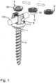
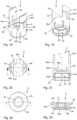
- Fig. 1:
- shows a perspective exploded view of an embodiment of a system including a bone anchoring device and different interchangeable fixation members.
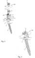
- Fig. 2:
- shows a perspective exploded view of a first embodiment of the bone anchoring device as shown in
Fig. 1 with a first fixation member. - Fig. 3:
- shows a perspective view of the bone anchoring device of
Fig. 2 in an assembled state. - Fig. 4:
- shows a cross-sectional view of the bone anchoring device of
Figs. 2 and 3 , the cross-section taken in a plane perpendicular to a longitudinal axis of the rod channel and extending through a center of the legs of the receiving part. - Fig. 5:
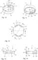
- shows a perspective view from a top of the receiving part of the bone anchoring device of
Figs. 1 to 4 . - Fig. 6:
- shows a perspective view from a bottom of the receiving part of
Fig. 5 . - Fig. 7:
- shows a top view of the receiving part of
Figs. 5 and 6 . - Fig. 8:
- shows a cross-sectional view of the receiving part of
Figs. 5 to 7 , the cross-section taken in a plane along line A-A inFig. 7 . - Fig. 9:
- shows a cross-sectional view of the receiving part of
Figs. 5 to 8 , the cross-section taken in a plane along line B-B inFig. 7 . - Fig. 10:
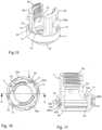
- shows a perspective view from a top of a variable configuration member in the form an outer ring of the bone anchoring device of
Figs. 1 to 4 . - Fig. 11:
- shows a perspective view from a bottom of the outer ring of
Fig. 10 . - Fig. 12:
- shows a top view of the outer ring of
Figs. 10 and 11 . - Fig. 13:
- shows a cross-sectional view of the outer ring of
Figs. 10 to 12 , the cross-section taken in a plane along line D-D inFig. 12 . - Fig. 14:
- shows a cross-sectional view of the outer ring of
Figs. 10 to 13 , the cross-section taken in a plane along line F-F inFig. 12 . - Fig. 15:
- shows a perspective view from the top of the receiving part of
Figs. 5 to 9 with the outer ring ofFigs. 10 to 14 mounted thereon. - Fig. 16:
- shows a top view of the receiving part with mounted outer ring of
Fig. 15 . - Fig. 17:
- shows a cross-sectional view of the receiving part with mounted outer ring of
Figs. 15 and 16 , the cross-section taken in a plane along line G-G inFig. 16 . - Fig. 18:
- shows a perspective view from a top of the pressure member of the bone anchoring device shown in
Figs. 1 to 4 . - Fig. 19:
- shows a perspective view from a bottom of the pressure member of
Fig. 18 . - Fig. 20:
- shows a top view of the pressure member of
Figs. 18 and 19 . - Fig. 21:
- shows a cross-sectional view of the pressure member of
Figs. 18 to 20 , the cross-section taken in a plane along line H-H inFig. 20 . - Fig. 22:
- shows a top view of the first fixation member of the polyaxial bone anchoring device of
Figs. 1 to 4 . - Fig. 23:
- shows a cross-sectional view of the first fixation member of
Fig. 22 , the cross-section taken in a plane along line I-I inFig. 22 . - Fig. 24a to Fig. 24f:
- show steps of assembling the polyaxial bone anchoring device of
Figs. 1 to 4 and using it with a rod, whereinFig. 24f is an enlarged view of a detail ofFig. 24e . - Fig. 25:
- shows a top view of a second fixation member of the system shown in
Fig. 1 . - Fig. 26:
- shows a cross-sectional view of the second fixation member of
Fig. 25 , the cross-section taken in a plane along line J-J inFig. 25 . - Fig. 27:
- shows a cross-sectional view of the polyaxial bone anchoring device of
Fig. 1 with the second fixation member ofFigs. 25 and 26 , the cross-section taken in a plane perpendicular to the longitudinal axis of the rod channel and extending through a center of the legs of the receiving part. - Fig. 28:
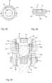
- shows a top view of a third fixation member of the polyaxial bone anchoring device of
Figs. 1 to 4 . - Fig. 29:
- shows a cross-sectional view of the third fixation member of
Fig. 28 , the cross-section taken in a plane along line K-K inFig. 28 . - Fig. 30:
- shows a cross-sectional view of the polyaxial bone anchoring device of
Figs. 1 to 4 with the third fixation member ofFigs. 28 and 29 , the cross-section taken in a plane perpendicular to the rod channel and extending through a center of the legs. - Fig. 31:
- shows a perspective view of a second embodiment of the polyaxial bone anchoring device with the first fixation member in an assembled state.
- Fig. 32:
- shows a cross-sectional view of the polyaxial bone anchoring device of
Fig. 31 , the cross-section taken in a plane perpendicular to the rod channel and extending through a center of the legs of the receiving part. - Fig. 33:
- shows a perspective view of a third embodiment of the bone anchoring device in the form of a monoaxial bone anchoring device with the first fixation member in an assembled state.
- Fig. 34:
- shows a cross-sectional view of the bone anchoring device of
Fig. 33 , the cross-section taken in a plane perpendicular to the longitudinal axis of the rod channel and extending through a center of the legs. - Referring to
Figs. 1 to 4 , a bone anchoring device according to a first embodiment is a polyaxial axial bone anchoring device. It includes abone anchoring element 1 having ashank 2 with a threaded portion and ahead 3. Thehead 3 comprises a spherically-shaped outer surface portion and, on its side opposite to theshank 2, arecess 4 for engagement with a tool. A receivingpart 5 is provided for coupling thebone anchoring element 1 to arod 100. In the receivingpart 5, apressure member 6 is arranged to exert pressure onto thehead 3 of thebone anchoring element 1. Additionally, the bone anchoring device includes a variable configuration member in the form of anouter ring 7 that is configured to be mounted around the receivingpart 5. Theouter ring 7 is further configured to provide a support for therod 100 when therod 100 is placed into the receivingpart 5. - Moreover, the bone anchoring device may further include a
first fixation member 8 that is configured to cooperate with the receivingpart 5 to secure therod 100 in the receivingpart 5. In addition, a second fixation member 8' and athird fixation member 8" may be provided wherein the three fixation members are all interchangeably usable with the bone anchoring device. The second fixation member 8' is configured to cooperate with the receivingpart 5, that is pre-assembled with theouter ring 7 and with thepressure member 6, such that thehead 3 is clamped or locked and therod 100 is maintained axially movable. Thethird fixation member 8" is configured to cooperate with the receivingpart 5, that is pre-assembled with theouter ring 7 and thepressure member 6, such that therod 100 and thehead 3 can be locked simultaneously. Thus, the polyaxial bone anchoring device and the first, the second and the third fixation members form a modular system, in particular a modular system that can realize different functions of the polyaxial bone anchoring device. - The
rod 100 may be a cylindrical straight rod that is configured to stabilize bone parts or vertebrae connected through the rod. Preferably, the surface of therod 100 is smooth at least to such an extent, that therod 100 can slide along a fixation member when it touches the fixation member while not being fixed. It shall be noted that the rod is not limited to a straight rod as depicted in the embodiments but shall include any elongate stabilization member that is configured to be displaceably, in particular slidably, receivable in the receivingpart 5. - Turning now to
Figs. 5 to 9 , the receivingpart 5 will be described in greater detail. The receivingpart 5 has a first end ortop end 5a and a second end orbottom end 5b opposite to thetop end 5a. It may be of a substantially cylindrical outer shape with a central longitudinal axis C extending through thetop end 5a and thebottom end 5b. Coaxially with the central axis C, apassage 51 is provided that extends from thetop end 5a to thebottom end 5b and forms anopening 52 at thebottom end 5b. At a distance from thetop end 5a, thepassage 51 widens into anaccommodation space 53 that is configured to receive thehead 3 and at least a portion of thepressure member 6. Adjacent to theopening 52 at thebottom end 5b, theaccommodation space 53 narrows towards the opening 52 in a narrowingportion 53a, which may be, for example, a tapered, more particularly a conical surface that may cooperate with a corresponding portion of thepressure member 6. A width of theopening 52 may be greater than the greatest width E of the head 3 (Fig. 4 ), so that thehead 3 may be inserted from thebottom end 5b into theaccommodation space 53. To enable the insertion of thehead 3 from thebottom end 5b, the width of theaccommodation space 53 is such that thepressure member 6 can expand therein to permit the insertion of thehead 3. - The receiving
part 5 further comprises a substantiallyU-shaped recess 54 starting at thetop end 5a and extending in the direction of thebottom end 5b with a bottom 54a at the deepest position. By means of theU-shaped recess 54, twofree legs 55 are formed that define a channel for receiving therod 100. - On an inner surface of the
legs 55 aninternal thread 56 is formed which is in the exemplary embodiment a square thread or another flat thread. For cooperation with a portion of thepressure member 6, acircumferential groove 57 may be provided at the inner wall of thelegs 55 at a distance from the bottom 54a of theU-shaped recess 54. - In addition,
transverse holes 58 may extend through thelegs 55, respectively, in a direction perpendicular to the central axis C and at a position approximately at the center of thelegs 55 in the circumferential direction. Thetransverse holes 58 may serve foraccommodating pins 59 that extend through theholes 58 into the channel. Thepins 59 are configured to engage thepressure member 6 to form a securing structure to secure thepressure member 6 against rotation. In addition, thepins 59 may limit an upward movement of thepressure member 6. At the outside of thelegs 55, for example,longitudinal recesses 50 and/orattachment projections 50a may be provided for engagement with a tool or an instrument. - At an axial position below the bottom 54a of the substantially
U-shaped recess 54 and in the circumferential direction to the right and to the left of the bottom 54a on either side of the rod channel a holding structure for theouter ring 7 is provided. The holding structure may includegrooves 500 for engagement with a portion of theouter ring 7. Thegrooves 500 extend circumferentially in a portion of the outer surface of the receivingpart 5. More specifically, thegrooves 500 may have a circumferential length that may be less than a half, more particularly less than a quarter of the circumference of the receiving part. Hence, four such grooves may be formed, two on each end of the rod channel. - Each of the
grooves 500 has a rectangular contour in a front view and comprises aninner wall 500a which is sandwiched between anupper wall 500b that faces towards thebottom end 5b of the receivingpart 5 and alower wall 500c that faces towards thetop end 5a of the receivingpart 5. Theinner wall 500a may be flat such that the depth of the groove from the ends towards the center in the circumferential direction. Theupper wall 500b may be straight and more particularly may extend substantially perpendicular to the central axis C. Thelower wall 500c forms a stop for a portion of theouter ring 7. In greater detail, thelower wall 500c is inclined in such a manner that it forms an undercut. This permits an engagement with a portion of theouter ring 7 and prevents inadvertent removal of theouter ring 7 via thelower end 5b of the receivingpart 5 once theouter ring 7 has been mounted . When theouter ring 7 engages thegrooves 500, the orientation of the outer ring relative to the receiving part is maintained. Thus, the grooves also form a securing structure against inadvertent rotation of the outer ring. While one such groove may be sufficient, preferably for stability reasons at least two, more preferably four such grooves are provided. - Referring further to
Figs. 10 to 14 , theouter ring 7 comprises a first end orupper end 7a and an opposite second end orlower end 7b. An inner width of theouter ring 7 is such that theouter ring 7 fits around the receivingpart 5 in an axial region between the bottom 54a of theU-shaped recess 54 and thebottom end 5b. - At positions corresponding to the positions of the
grooves 500 in the outer surface of the receivingpart 5, theouter ring 7 has a counterpart holding structure in the form ofprotrusions 70 that are configured to engage thegrooves 500. More specifically, eachprotrusion 70 comprises aninner surface 70a that is configured to abut against theinner surface 500a of thegroove 500 when theouter ring 7 is mounted to the receivingpart 5. Anupper surface 70b of theprotrusion 70 may be inclined in such a manner that sliding of theouter ring 7 over the receivingpart 5 when theouter ring 7 is mounted from thelower end 5b is facilitated. An oppositelower surface 70c of theprotrusion 70 is inclined, preferably also having an undercut, in such a manner that thelower surface 70c can snap into the undercut provided by thelower surface 500c of thegroove 500 and preferably can hook therein (seeFig. 17 ). Thus, thelower surface 500c of thegroove 500 forms a stop for theouter ring 7 when theouter ring 7 is moved towards thesecond end 5b. Thesidewalls 70d of theprotrusion 70 may be concavely rounded to permit easy entrance into thegroove 500. The position of the protrusion in the axial direction and the distance of theprotrusion 70 from thelower end 7b may be such that once theprotrusion 70 has entered thegroove 500, the protrusions can move slightly in an axial direction in the groove. Corresponding to thegrooves 500, fourprotrusions 70 are formed. - At a position between two neighboring
protrusions 70 in the circumferential direction, anelevation 71 is formed at theupper end 7a of theouter ring 7. Hence, theouter ring 7 has twoelevations 71 that are offset by 180°. Theelevations 71 are configured to protrude above the bottom 54a of therecess 54 of the receivingpart 5 when theouter ring 7 has been mounted to the receivingpart 5. Ashallow depression 72 may be formed on the upper surface of eachelevation 71. Thedepression 72 functions as a first rod contact surface. - The
outer ring 7 may comprise inaddition stiffening structures 73. The stiffeningstructures 73 may be formed as protrusions that are offset from each other by 180° and located at a circumferential position approximately in the middle between theelevations 71 and an axial position preferably adjacent to or close to theupper end 7a of theouter ring 7. The shape of the protrusions may be similar to the shape of theprotrusions 70, however the radial thickness may be smaller as the stiffeningstructures 73 do not engage a groove in the receiving part. When pressure is exerted via the rod on the firstrod contact surface 72, the outer ring is deformed in such a manner that the ring shape of the outer ring is slightly changed in such a manner that the firstrod contact surface 72 at theelevations 71 is moved towards thelower end 5b of the receivingpart 5. The stiffeningstructures 73 enable such a defined deformation. Upon relieving the pressure, the outer ring can assume the original ring shape again. - It shall be noted that the design of the holding structure and of the stiffening structure is not limited to the specific shape shown but can have a different shape that results in the same function.
- An outer width of the
outer ring 7 may be such that the outer ring does not or does only minimally protrude beyond the outer surface of theprotrusions 50a of the receivingpart 5. - The outer ring preferably is made of such a material that the outer ring is flexible or deformable to some extent. In particular, the
outer ring 7 is deformable in such a manner that it is deformable when pressure is exerted onto the firstrod contact surface 72. Such a material is preferably a polymer material, more preferably a body-compatible polymer material, such as, for example polyether ether ketone (PEEK). Due to the material and to the shape, the outer ring may be elastically deformable, i.e. when a load that causes a deformation of theouter ring 7 is relieved, theouter ring 7 assumes its original shape. In addition, the material facilitates sliding of the rod when the rod is on the firstrod contact surface 72. - Referring now to
Figs. 18 to 21 , thepressure member 6 will be described. Thepressure member 6 may be formed as a monolithic part with a first orupper end 6a and a second orlower end 6b opposite to theupper end 6a. Adjacent to theupper end 6a, thepressure member 6 comprises a substantially cylindricalfirst portion 61 that is adapted to be received in thepassage 51 of the receivingpart 5 and to move therein in an axial direction. Adjacent to thelower end 6b, a second, substantiallycylindrical portion 62 is formed that is configured to extend at least partially into theaccommodation space 53 of the receivingpart 5. Further, adjacent to thelower end 6b, ahead receiving recess 63 that may be adapted to the spherical shape of thehead 3 is formed in thesecond portion 62. Thehead receiving recess 63 may be sized so as to frictionally hold thehead 3 of thebone anchoring element 1 therein. A widenedcylindrical portion 63a in thehead receiving recess 63 may enhance flexibility of thehead receiving recess 63 and may facilitate pivoting of thehead 3. Due to a plurality oflongitudinal slits 64 that are open to thesecond end 6b and preferably have widenedend portions 64a, thesecond portion 62 is rendered flexible. Adjacent to thelower end 6b, the outer surface of thesecond portion 62 comprises a narrowingportion 65, preferably a tapered and more preferably a conically-tapered portion that is configured to cooperate with the narrowingportion 53a of theaccommodation space 53. By means of the cooperating surfaces 65, 53a of thepressure member 6 and of the receivingpart 5, respectively, the flexiblesecond portion 62 of thepressure member 6 can be compressed to clamp or lock thehead 3 in thehead receiving recess 63. - Adjacent to the
upper end 6a, a substantiallyU-shaped recess 66 forms twoopen legs 67 that preferably have substantially flat inner walls. The substantiallyU-shaped recess 66 comprises anelevated base 68 with asurface 68a that has substantially V-shaped contour with a rounded bottom. Thesurface 68a forms a second rod contact surface that is in this embodiment configured to receive rods of different diameters thereon. Moreover, thesupport surface 68a lies at such an axial height with respect to theupper end 6a of thepressure member 6 that, when a rod of the greatest possible diameter rests on the secondrod contact surface 68a, theupper end 6a of the pressure member, more in detail of thelegs 67 projects above the upper surface of the rod. By means of theelevated base 68, twogrooves 69 are formed between the right and the left side of theelevated base 68 and thelegs 67. Thereby thelegs 67 may be slightly radially flexible. The end surface at theupper end 6a of thepressure member 6 may have a substantially roof-shaped cross-section with an inclinedinner surface 601 and an inclinedouter surface 602 that may be shorter than the inclinedinner surface 601. - Lastly, the
pressure member 6 includes acoaxial bore 60 that serves for accessing therecess 4 of thehead 3 with a tool. In addition, at approximately at the center of each of thelegs 67 in a circumferential direction, an axiallyelongate hole 69 is provided that is configured to be engaged by thepins 59. The corporation between thepins 59 and theelongate holes 69 prevents rotation of thepressure member 6 with respect to the receivingpart 5. Furthermore, thepins 59 form a stop for an upward movement of thepressure member 6, when thehead 3 is inserted through thelower opening 52 of the receivingpart 5 into thehead receiving recess 63 of thepressure member 6. Above theelongate recesses 69circumferentially extending projections 600 with a substantially flat upper surface may be provided that are configured to engage thegroove 57 of the receivingpart 5. By means of this, a pre-locking position of thepressure member 6 in the receivingpart 5 can be secured as described below. - Referring to
Figs. 22 and 23 , thefirst fixation member 8 is formed as a set screw with anupper end 8a and an oppositelower end 8b. In theupper end 8a, a tool-receivingrecess 81 is provided that may have, for example, a torx-shape. In addition, at to theupper end 8a, acircumferentially extending flange 82 is formed that protrudes in a radial direction beyond theouter thread 83 of the set screw. At thelower end 8b arecess 84 receives aninsert 85. Theinsert 85 may be disc-shaped with a substantially circular outer contour that is held, for example, via a press-fit connection in therecess 84. An axial thickness of the disc-shapedinsert 85 may be such that alower surface 85a of theinsert 85 protrudes slightly out of thelower end 8b of thefirst insert 8. Its outer diameter is slightly smaller than the distance between the inner surfaces of thelegs 67 of thepressure member 6 such that the insert can extend between thelegs 67 preferably without exerting a force onto thepressure member 6. Theinsert 85 is preferably made of a material that facilitates sliding of the rod along thelower surface 85a. More specifically, theinsert 85 may be made of a polymer, particularly of a body-compatible polymer, such as PEEK. - The
flange 82 functions as a stop to limit the advancement of thefirst fixation member 8 between thelegs 55. An axial length of thefirst fixation member 8 is such that when thefirst fixation member 8 is inserted between thelegs 55 of the receivingpart 5 and screwed downward until theflange 82 abuts against thetop end 5a of the receiving part, neither thelower surface 85a nor thelower end 8a of thefirst fixation member 8 exerts a downward axial force onto thepressure member 6. In other words, thepressure member 6 remains unaffected by thefirst fixation member 8 when theflange 82 abuts against thetop end 5a of the receivingpart 5. Preferably, there is a small gap between theupper end 6a of thepressure member 6 and the surface at thelower end 8b of thefirst fixation member 8. Moreover, the axial length of the first fixation member is such that there is agap 800 between the upper surface of therod 100 and thelower surface 85a of thefirst fixation member 8. The size of thegap 800 depends on the size of the rod. In some cases, the gap is so small so that therod 100 is configured to slide along thelower surface 85a. In the clinical use, if thegap 800 is large enough, the rod may even move freely without contacting thefirst fixation member 8 nor thepressure member 6. Alternatively, the axial length of the portion offirst fixation member 8 that protrudes into the rod channel and/or the diameter of the rod may be such that the rod slides along the lower side of the first fixation member and on the firstrod contacting surface 72 of theouter ring 7. - The bone anchoring element, the receiving part and the pressure member as well as the rod and the fixation member may be made of the same or of different materials, preferably of a bio-compatible material such as titanium or stainless steel or a bio-compatible alloy, such as NiTi alloys, for example Nitinol, or from a bio-compatible plastic material, for example, polyether ether ketone (PEEK).
- The receiving
part 5, thepressure member 6 and theouter ring 7 usually are pre-assembled before using them with a bone anchoring element and a rod. For assembly, thepressure member 6 is inserted through thetop end 5a into the receiving part such that thehead receiving recess 63 extends into theaccommodation space 53. The secondrod contact surface 68a of thepressure member 6 is aligned with theU-shaped recess 54. Thepressure member 6 is secured against rotation by thepins 59 which extend through the through-holes 58 of the receiving part into theelongate holes 69 of the pressure member. In this configuration, thepressure member 6 can move along an axial distance which is limited by the abutment of thepins 59 against the lower end of the elongate holes 69. Theouter ring 7 is mounted from thelower end 5b onto the receivingpart 5. Thereby, theouter ring 7 is oriented with respect to the receivingpart 5 such that theelevations 71 with therod support 72 are aligned with theU-shaped recess 54 of the receivingpart 5. Theouter ring 7 is then shifted over the receivingpart 5 until the inclinedlower surface 70c of theprotrusion 70 snaps into thegroove 500 and hooks into the inclinedlower surface 500c of thegroove 500. As a result, theouter ring 7 is secured against removal through thelower end 5b of the receiving part and/or against rotation. - In use, referring to
Figs. 24a to 24f , the receivingpart 5 which is pre-assembled with thepressure member 6 and theouter ring 7 is configured to be connected to thebone anchoring element 1. In a first method of use, thebone anchoring element 1 has been inserted into a bone part or avertebra 1000 prior to coupling the receivingpart 5 to thehead 3, as shown inFig. 24a . Thehead 3 of thebone anchoring element 1 projects out of the bone surface and the pre-assembled receiving part is placed with thelower end 5b towards thehead 3 as shown inFig. 24b . When thehead 3 enters into thehead receiving recess 63, thepressure member 6 is moved upwards in thepassage 51 until further upward movement is limited by thepins 59. The flexiblesecond portion 62 of thepressure member 6 expands in theaccommodation space 53 and snaps onto thehead 3 as shown inFig. 24c . Thereafter, the receivingpart 5 is pulled slightly away from the head and thepressure member 6, so that the cooperatingsurfaces 53a of the receivingpart pressure member 6 engage to preliminarily hold the head in a receiving part in a pivotable manner as shown inFig. 24d . This is a pre-locking position where thehead 3 is prevented from removal through thelower opening 52. In the pre-locking position of thepressure member 6, theprojections 600 on thelegs 67 are within thegrooves 57 at the receivingpart 5 and prevent upward movement of thepressure member 6 out of the pre-locking position. It shall be noted that the size of the head and the head receiving recess may be selected such, that in the pre-locking position of thepressure member 6, the head may be temporarily held by friction in a particular angular position and can be pivoted to another angular position in which it is held again by friction when applying a force to overcome the frictional force, such as manually pivoting the receiving part relative to the head. - Referring in greater detail to
Fig. 24d , theouter ring 6 projects with theelevations 71 and the firstrod contact surface 72 at least partially above the secondrod contact surface 68a of thepressure member 6. - Referring to
Figs. 24e and 24f , therod 100 is inserted and thefixation member 8 is screwed between thelegs 55 of the receivingpart 5. Therod 100 rests on the firstrod contact surface 72 of theouter ring 7.Fig. 24f shows thesmall gap 800 between the upper surface of therod 100 and thelower surface 85a of thefixation member 8. As thefixation member 8 abuts against theupper end 5a of the receivingpart 5, therod 100 remains freely movable in the axial direction within the receiving part. At the same time, thehead 3 remains pivotable with respect to thepressure member 6 and the receivingpart 5. Thelower surface 8b of the fixation member preferably does not exert an axial force onto thepressure member 6. - In an alternative method of use, the
bone anchoring element 1 can be coupled to the receivingpart 5 prior to insertion of theshank 2 into bone. - The
fixation member 8 can be used to produce a bone anchoring device that allows movement of the rod and movement of the head in the receiving part at the same time. This could be used, for example, in a growing rod construct. This opens further possibilities of correction steps in which it may be advantageous to keep also the receiving part pivotable relative to the shank. - Referring to
Figs. 25 to 27 a second embodiment of the bone anchoring device comprises the second fixation member 8'. All other parts are identical or highly similar to the first embodiment. The second fixation member 8' is similar to the first fixation member except that it lacks theflange 82 and therefore can be screwed deeper into the rod channel. All parts and portions that are identical or highly similar to that of the first fixation member are marked with the same reference numerals and the description thereof is not repeated. A maximum outer width of the second fixation member is defined by the outer diameter of thethread 83. The surface at thelower end 8b in this embodiment may be concavely shaped to match the corresponding convexly shaped upper end surface of the legs of thepressure member 6. In greater detail, the surface at thelower end 8b of the second fixation member 8' has an inclinedinner surface 801 that is in the cross-sectional view longer than an inclinedouter surface 802, which in combination are concavely roof-shaped. The convexly shaped upper end surfaces 601, 602 of the pressure member and the concavely shaped matchingend surfaces legs 55 of the receiving part. Thereby, the connection in the radial direction is improved and a radial play that could lead to an inhomogeneous pressure onto thepressure member 6 may be reduced. - An axial length of the second fixation member 8' is such that when the second fixation member is tightened, the second fixation member 8' presses onto the
pressure member 6 so that thepressure member 6 is moved downwards until the cooperating surfaces 65 of thepressure member part 5 engage to clamp thehead 3. In this configuration as shown inFig. 27 , therod 100 rests on theouter ring 7 while there is agap 800 between thelower surface 85a of theinsert member 85 and the upper surface of the rod, such that the rod can slide within the receiving part. - Referring to
Figs. 28 to 30 , a third embodiment of the polyaxial bone anchoring device comprises thethird fixation member 8". The third fixation member is a set screw with anupper end 8a and alower end 8b and atool engagement recess 81 that extends from theupper end 8a towards thelower end 8b. Thethird fixation member 8" further has aprojection 86, preferably a cylindrical projection, at thelower end 8b with afree end surface 86a. An outer width of theprojection 86 is smaller than an inner width of thepressure member 6 between thelegs 67. Thus, when thethird fixation member 8" is inserted between thelegs 55 of the receivingpart 5, theprojection 86 can enter between thelegs 67 of thepressure member 6 without touching thepressure member 6. The length of theprojection 86 in the axial direction is such that when thethird fixation member 8" is inserted between thelegs 55 of the receivingpart 5, thelower surface 86a of theprojection 86 presses onto the surface of an insertedrod 100. When thethird fixation member 8" exerts pressure onto therod 100, the rod exerts pressure in turn onto theouter ring 7. Theouter ring 7 is deformed until the rod rests on therod contact surface 68a of thepressure member 6. The rod may simultaneously still contact the firstrod support surface 72 of the outer ring. - Hence, the
outer ring 7 is configured to change between a first configuration and a second configuration. In the first configuration, theouter ring 7 is non-deformed and theelevations 71 of theouter ring 7 project above the secondrod contact surface 68a of thepressure member 6. In the second configuration, theouter ring 7 is deformed and theelevations 71 with the firstrod contact surface 72 no longer extend above the secondrod contact surface 68a of thepressure member 6 such that therod 100 rests on the secondrod contact surface 68a of thepressure member 6. The deformation is reversible. This means that when the pressure onto theouter ring 7 is relieved, theouter ring 7 re-assumes the first configuration. - In use, as depicted in
Fig. 30 , tightening thethird fixation member 8" results in an axial force via theprojection 86 onto the insertedrod 100. As a result, while tightening thethird fixation member 8", thehead 3 and therod 100 are locked in the receivingpart 5 simultaneously. - Referring to
Figs. 31 and 32 , a still further embodiment of the polyaxial bone anchoring device is described. The polyaxial bone anchoring device differs from the embodiments ofFigs. 1 to 30 in the design of the pressure member and the receiving part. The receiving part 5' comprises adjacent to thelower end 5b aseat 53a' for thehead 3 of thebone anchoring element 1 in which thehead 3 is pivotably supported. The lower opening 52' has an inner diameter that is smaller than the greatest diameter E of thehead 3. Thus, thebone anchoring element 1 has to be inserted from theupper end 5a of the receiving part and guided with theshank 2 through the lower opening 52' until thehead 3 rests in theseat 53a'. The accommodation space 53' is configured to accommodate a portion of thehead 3 and a portion of the pressure member 6'. The pressure member 6' has a lower portion 62' with a spherical recess 63' that is configured to cover thehead 3 above the region with the greatest outer diameter E and to exert pressure onto thehead 3. The lower portion 62' has a substantially cylindrical outer surface and is configured to move in the passage 51' of the receiving part 5'. It shall be noted that theseat 5 3 a' may also have any shape that allows thehead 3 to pivot therein like a ball and socket joint. For example, theseat 53a' may also be conically-shaped. - As the bone anchoring device according to
Figs. 31 and 32 is a top-loading bone anchoring device in which theanchoring element 1 is inserted from theupper end 5a into the receiving part 5', the polyaxial bone anchoring device can be inserted into bone with the receiving part 5', the pressure member 6', thebone anchoring element 1 and theouter ring 7 pre-assembled. In the Figures, thefirst fixation member 8 is shown in use with the polyaxial bone anchoring device. When thefixation member 8 is tightened, the rod rests on theouter ring 7 and is still movable as there is thegap 800 between the uppermost surface of the rod and thelower surface 85a of theinsert 85. The pressure member 6' may have short legs 67' that do not project over the rod surface. Hence, the pressure member 6' does not exert pressure onto thehead 3. Thus, in the embodiment shown inFigs. 31 and 32 , thehead 3 is still pivotable and therod 100 is movable when the first fixation member is tightened. - Using the
third fixation member 8" ofFigs. 28 and 29 , allows to fix the rod and the head simultaneously by pressing theprojection 86 onto the rod which in turn presses onto thepressure member 6 thereby locking also thehead 3. - In a further modification of this embodiment, the pressure member 6' also comprises legs that extend above the uppermost surface of an inserted rod. Hence, in such a modification also the second fixation member 8' according to
Figs. 25 and 26 can be used to lock the head and to leave the rod movable. - Referring to
Figs. 33 and 34 , a further embodiment of the bone anchoring device is described. The bone anchoring device is a mono-axial bone anchoring device. This means, that the shank 2' and the receivingpart 5" are not pivotable with respect to each other. The receivingpart 5" has an outer appearance that is highly similar to that of the receiving part 5' of the previous embodiments. Theshank 2" is in this embodiment monolithic with the receivingpart 5". A second rod support is formed by the bottom 54a' of the substantiallyU-shaped recess 54 that defines the channel for receiving the rod. As shown inFig. 34 , the secondrod contact surface 54a" has a substantially V-shaped contour preferably with a rounded bottom for receiving rods of different diameters. Theouter ring 7 projects at least partially with theextensions 71 above the secondrod contact surface 54a" so that therod 100 can rest on the firstrod contact surface 72 of theouter ring 7. - The bone anchoring device is shown with the
first fixation member 8. Therefore, when thefirst fixation member 8 is tightened, therod 100 is still movable in the rod channel and can slide along thelower surface 85a of the third fixation member and on the firstrod contact surface 72 of theouter ring 7. - Alternatively, when the
third fixation member 8" is used, theprojection 86 presses onto the rod when thethird fixation member 8" is tightened. As a result, the outer ring is deformed and therod 100 is pressed against the secondrod contact surface 54a' of the receivingpart 5". Hence, by selecting the suitable fixation member, the mono-axial bone anchoring device can be used as a bone anchoring device that allows the rod freely to slide or as a bone anchoring device which allows the rod to be fixed. - Modifications of the above described embodiments are conceivable. In particular, the shape of the parts is not limited to the detailed shape shown in the Figures. Deviations may be possible and encompassed by the disclosure. The variable configuration member is shown as a closed ring. However, the variable configuration member can be also a member that is partially arranged in the rod channel and is deformable upon pressure exerted by the rod onto it.
- Also, a two-part fixation member may be included in the system with an outer member and an inner member. The receiving part and the pressure member are not limited to the detailed shape shown. The receiving part and/or the pressure element may also have a two-part design. The rod contact surface in the pressure member may be flat or cylindrical. Also, the pressure member in the first embodiment can have short legs that do not project above a surface of an inserted rod. Also, the receiving part may have extended tabs which prolong the legs. Such a receiving part may be used, for example, for reduction procedures in which vertebrae or bone parts are realigned.
- In a further modification, the receiving part can be designed to have two rod channels so that two sliding rods may be employed. With the selection of a suitable fixation member one or both rods can be fixed.
- For the bone anchoring element, all types of bone anchoring elements are suitable for anchoring in bone or a vertebra may be used, in particular also bone nails
- The rod may have various shaped and/or varying cross-section along its length. The rod may be stiff or more flexible. It may also be, for example, a cord or a tether.
Claims (15)
- A bone anchoring device for anchoring a rod to a bone or vertebra via a shank to be anchored in bone, the bone anchoring device comprisinga receiving part (5, 5', 5") connectable or connected to the shank (2, 2'), the receiving part comprising two legs (55) that define a channel for the rod; anda variable configuration member (7) configured to allow the bone anchoring device to provide a variable functionality;wherein the variable configuration member (7) provides a first rod contact surface (72) that is arranged outside of the receiving part (5, 5', 5") and a second rod contact surface (68a, 54a') is provided in the receiving part (5, 5', 5"); andwherein the variable configuration member (7) is adjustable from a first configuration in which an inserted rod (100) can contact the first rod contact surface (72) and a second configuration in which an inserted rod (100) is supported by the second rod contact surface (68a, 54a').
- The bone anchoring device of claim 1, wherein the variable configuration member (7) is deformable in at least a portion thereof so as to change from the first configuration to the second configuration, preferably wherein the variable configuration member (7) is elastically deformable, more preferably wherein the variable configuration member (7) is at least partially made of a material that exhibits flexibility, such as a plastic material, particularly a polymer material, more particularly PEEK
- The bone anchoring device of claim 1 or 2, wherein in the second configuration, an inserted rod is also supported by the first rod contact surface (72).
- The bone anchoring device of one of claims 1 to 3, wherein the variable configuration member (7) is positionable around a wall portion of the receiving part (5, 5', 5") that encompasses an inserted head (3) of the bone anchoring element (1), preferably wherein the wall portion remains unaffected when the variable configuration member (7) changes from the first to the second configuration.
- The bone anchoring device of one of claims 1 to 4, wherein the variable configuration member is an outer ring (7) positionable around the receiving part (5, 5', 5").
- The bone anchoring device of one of claims 1 to 5, wherein the variable configuration member (7) and the receiving part (5, 5', 5") comprise a rotation preventing structure (500, 70) that secures the variable configuration member (7) against rotation relative to the receiving part (5, 5', 5").
- The bone anchoring device of one of claims 1 to 6, wherein the variable configuration member (7) comprises a stiffening structure (73), preferably being arranged offset relative to the rod channel, more preferably being arranged at about 90° to the rod channel.
- The bone anchoring device of one of claims 1 to 7, wherein the receiving part (5, 5', 5") comprises a first end (5a) formed by a free end of the legs (55) and an opposite second end (5b) and wherein the variable configuration member (7) is mountable from the second end (5b), preferably wherein a stop (500c) is provided that inhibits removal of the variable configuration member (7) towards the second end (5b) after mounting.
- The bone anchoring device of one of claims 1 to 8, wherein the shank (2) is part of a bone anchoring element (1) with a head (3) that is connectable to the receiving part (5, 5') and wherein a pressure member (6, 6') is arranged in the receiving part (5, 5') for exerting pressure onto an inserted head (3), the pressure member (6, 6') comprising the second rod contact surface (68a).
- The bone anchoring device of claim 9, wherein the pressure member (6, 6') is positionable in the receiving part (5, 5') such that in a first position the head (3) is freely movable and in a second position the pressure member (6, 6') exerts pressure onto the head, preferably wherein in the first position the variable configuration member (7) is in the first configuration and in the second position the variable configuration member (7) is in the first or in the second configuration.
- The bone anchoring device of claim 9 or 10, wherein the pressure member (6) comprises two legs (67) extending from the first rod contact surface (68a) to a height above an upper surface of an inserted rod (100).
- The bone anchoring device of one of claims 1 to 11, further comprising a first fixation member (8), preferably a set screw, that is configured to engage the receiving part (5, 5', 5") between the legs (55) and that has a size such that an inserted rod can slide along a lower surface of the first fixation member or such that there is a gap (800) between an upper surface of an inserted rod (100) and a lower surface of the first fixation member (8), preferably wherein the first fixation member (8) is configured abut against the legs (55) of the receiving part to limit an insertion depth, further preferably the first fixation member (8) comprising a portion (85) that facilitates sliding of the rod (100) relative thereto.
- The bone anchoring device of claim 11 or 12, wherein a second fixation member (8'), preferably a set screw, is provided that cooperates with the legs (55) of the receiving part and that is configured to secure the rod (100) in the receiving part (5, 5') while a head is clamped and the rod (100) is displaceable, preferably the second fixation member (8') comprising a portion (85) that facilitates sliding of the rod (100) relative thereto.
- The bone anchoring device of one of claims 1 to 12, wherein a third fixation member (8") preferably a set screw, is provided that cooperates with the legs (55) of the receiving part (5, 5', 5") and that comprises a projection (86) configured to act via the rod (100) onto the variable configuration member (7) to change the variable configuration member (7) from the first configuration to the second configuration.
- A system of a bone anchoring device of one of claims 1 to 14 and at least a first fixation member (8) of claim 13 and/or a second fixation member (8') of claim 14 and/or a third fixation member (8") of claim 15 that can be used with the bone anchoring device interchangeably, preferably the system further including a rod (100), further preferably wherein the variable configuration member (7) is configured to change the configuration from the first configuration to the second configuration by pressure exerted by the rod (100) onto the first rod contact surface (72).
Priority Applications (3)
| Application Number | Priority Date | Filing Date | Title |
|---|---|---|---|
| EP21183181.3AEP4111992B1 (en) | 2021-07-01 | 2021-07-01 | Bone anchoring device |
| US17/851,659US12171467B2 (en) | 2021-07-01 | 2022-06-28 | Bone anchoring device |
| US18/950,862US20250143753A1 (en) | 2021-07-01 | 2024-11-18 | Bone anchoring device |
Applications Claiming Priority (1)
| Application Number | Priority Date | Filing Date | Title |
|---|---|---|---|
| EP21183181.3AEP4111992B1 (en) | 2021-07-01 | 2021-07-01 | Bone anchoring device |
Publications (2)
| Publication Number | Publication Date |
|---|---|
| EP4111992A1 EP4111992A1 (en) | 2023-01-04 |
| EP4111992B1true EP4111992B1 (en) | 2024-01-31 |
Family
ID=76744721
Family Applications (1)
| Application Number | Title | Priority Date | Filing Date |
|---|---|---|---|
| EP21183181.3AActiveEP4111992B1 (en) | 2021-07-01 | 2021-07-01 | Bone anchoring device |
Country Status (2)
| Country | Link |
|---|---|
| US (2) | US12171467B2 (en) |
| EP (1) | EP4111992B1 (en) |
Family Cites Families (64)
| Publication number | Priority date | Publication date | Assignee | Title |
|---|---|---|---|---|
| US5520690A (en)* | 1995-04-13 | 1996-05-28 | Errico; Joseph P. | Anterior spinal polyaxial locking screw plate assembly |
| US5882350A (en)* | 1995-04-13 | 1999-03-16 | Fastenetix, Llc | Polyaxial pedicle screw having a threaded and tapered compression locking mechanism |
| US5669911A (en)* | 1995-04-13 | 1997-09-23 | Fastenetix, L.L.C. | Polyaxial pedicle screw |
| ES2211964T3 (en)* | 1995-07-13 | 2004-07-16 | Fastenetix, L.L.C. | MECHANISMS OF POLIAXIAL LOCK. |
| US5575792A (en)* | 1995-07-14 | 1996-11-19 | Fastenetix, L.L.C. | Extending hook and polyaxial coupling element device for use with top loading rod fixation devices |
| US6488681B2 (en) | 2001-01-05 | 2002-12-03 | Stryker Spine S.A. | Pedicle screw assembly |
| KR100379194B1 (en) | 2001-10-31 | 2003-04-08 | U & I Co Ltd | Apparatus for fixing bone |
| DE10320417A1 (en) | 2003-05-07 | 2004-12-02 | Biedermann Motech Gmbh | Dynamic anchoring device and dynamic stabilization device for bones, in particular for vertebrae, with such an anchoring device |
| US7204838B2 (en) | 2004-12-20 | 2007-04-17 | Jackson Roger P | Medical implant fastener with nested set screw and method |
| US7090674B2 (en)* | 2003-11-03 | 2006-08-15 | Spinal, Llc | Bone fixation system with low profile fastener |
| CN1654026A (en) | 2004-02-11 | 2005-08-17 | 英属维京群岛商冠亚股份有限公司 | Vertebrae repositioning device with rotary buttoned round head |
| US8267969B2 (en)* | 2004-10-20 | 2012-09-18 | Exactech, Inc. | Screw systems and methods for use in stabilization of bone structures |
| WO2006047711A2 (en) | 2004-10-25 | 2006-05-04 | Alphaspine, Inc. | Pedicle screw systems and methods |
| ATE536821T1 (en)* | 2004-11-23 | 2011-12-15 | Roger P Jackson | POLYAXIAL BONE SCREW WITH MULTIPLE SHAFT FIXATION |
| US9168069B2 (en) | 2009-06-15 | 2015-10-27 | Roger P. Jackson | Polyaxial bone anchor with pop-on shank and winged insert with lower skirt for engaging a friction fit retainer |
| US7708762B2 (en) | 2005-04-08 | 2010-05-04 | Warsaw Orthopedic, Inc. | Systems, devices and methods for stabilization of the spinal column |
| TWI375545B (en) | 2005-04-25 | 2012-11-01 | Synthes Gmbh | Bone anchor with locking cap and method of spinal fixation |
| WO2008137933A1 (en) | 2005-05-25 | 2008-11-13 | Alpinespine Llc | Low rider pedicle screw system |
| WO2006127992A2 (en)* | 2005-05-25 | 2006-11-30 | Alphaspine, Inc. | Low profile pedicle screw and rod assembly |
| ES2326123T3 (en) | 2005-05-27 | 2009-10-01 | Biedermann Motech Gmbh | RECEPTION PART TO CONNECT A VARTAGE OF AN OSEO ANCHORAGE ELEMENT WITH A BEAR ANCHORAGE BAR AND DEVICE WITH SUCH A RECEPTION PART. |
| EP1769761B1 (en) | 2005-07-12 | 2008-09-10 | BIEDERMANN MOTECH GmbH | Bone anchoring device |
| US7717943B2 (en)* | 2005-07-29 | 2010-05-18 | X-Spine Systems, Inc. | Capless multiaxial screw and spinal fixation assembly and method |
| EP1926443B1 (en)* | 2005-09-23 | 2013-04-03 | Synthes GmbH | Bone support apparatus |
| WO2007041702A2 (en)* | 2005-10-04 | 2007-04-12 | Alphaspine, Inc. | Pedicle screw system with provisional locking aspects |
| WO2007075454A1 (en) | 2005-12-19 | 2007-07-05 | Synthes (U.S.A) | Polyaxial bone anchor with headless pedicle screw |
| US8162990B2 (en)* | 2006-11-16 | 2012-04-24 | Spine Wave, Inc. | Multi-axial spinal fixation system |
| US8167912B2 (en)* | 2007-02-27 | 2012-05-01 | The Center for Orthopedic Research and Education, Inc | Modular pedicle screw system |
| ES2348814T3 (en) | 2007-07-31 | 2010-12-15 | Biedermann Motech Gmbh | ANCHORAGE DEVICE Ã “SEO. |
| DE102007042953B4 (en) | 2007-08-30 | 2015-01-22 | Aesculap Ag | Orthopedic retention system |
| US8398683B2 (en)* | 2007-10-23 | 2013-03-19 | Pioneer Surgical Technology, Inc. | Rod coupling assembly and methods for bone fixation |
| ES2373690T3 (en) | 2007-12-13 | 2012-02-07 | Biedermann Motech Gmbh | ANCHORAGE DEVICE FOR ANCHORING A ROD IN A BONE OR VERTEBRA. |
| WO2009124196A2 (en) | 2008-04-03 | 2009-10-08 | Life Spine, Inc. | Top loading polyaxial spine screw assembly with one step lockup |
| ES2375526T3 (en)* | 2008-06-19 | 2012-03-01 | Biedermann Motech Gmbh | BONE ANCHORAGE ASSEMBLY. |
| US9408649B2 (en) | 2008-09-11 | 2016-08-09 | Innovasis, Inc. | Radiolucent screw with radiopaque marker |
| CA2742399A1 (en)* | 2008-11-03 | 2010-06-03 | Dustin M. Harvey | Uni-planar bone fixation assembly |
| US20100160978A1 (en) | 2008-12-23 | 2010-06-24 | John Carbone | Bone screw assembly with non-uniform material |
| ES2548580T3 (en) | 2009-02-20 | 2015-10-19 | Biedermann Technologies Gmbh & Co. Kg | Receiving part for housing a rod for coupling to a bone anchoring element and bone anchoring device that includes such receiving part |
| EP2283786B1 (en)* | 2009-08-12 | 2015-06-17 | Biedermann Technologies GmbH & Co. KG | A receiving part for receiving a rod for coupling the rod to a bone anchoring element |
| EP2286748B1 (en) | 2009-08-20 | 2014-05-28 | Biedermann Technologies GmbH & Co. KG | Bone anchoring device |
| EP2462888B1 (en)* | 2010-12-10 | 2015-02-18 | Biedermann Technologies GmbH & Co. KG | Receiving part for receiving a rod for coupling the rod to a bone anchoring element and bone anchoring device with such a receiving part |
| US9060812B2 (en) | 2011-03-29 | 2015-06-23 | Alphatec Spine, Inc. | Screw assembly with deformable bushing |
| EP2559389B1 (en)* | 2011-08-18 | 2013-04-03 | Biedermann Technologies GmbH & Co. KG | Polyaxial bone anchoring device |
| EP2591738A1 (en)* | 2011-11-14 | 2013-05-15 | Biedermann Technologies GmbH & Co. KG | Polyaxial bone anchoring device |
| US9700355B2 (en) | 2011-11-23 | 2017-07-11 | Aaron M. Longtain | Pedicle screw assembly |
| EP2837347B1 (en) | 2012-01-30 | 2018-10-03 | Biedermann Technologies GmbH & Co. KG | Bone anchoring device |
| ES2527766T3 (en)* | 2012-05-29 | 2015-01-29 | Biedermann Technologies Gmbh & Co. Kg | Receiver piece for receiving and housing a bar in order to couple it with a bone anchoring element, and bone anchoring device with such a receiving piece |
| EP2674123B1 (en) | 2012-06-11 | 2018-03-21 | Biedermann Technologies GmbH & Co. KG | Polyaxial bone anchoring device |
| EP2687171B1 (en) | 2012-07-18 | 2015-04-22 | Biedermann Technologies GmbH & Co. KG | Polyaxial bone anchoring device |
| US9763702B2 (en) | 2012-11-16 | 2017-09-19 | DePuy Synthes Products, Inc. | Bone fixation assembly |
| ES2611158T3 (en) | 2013-07-24 | 2017-05-05 | Biedermann Technologies Gmbh & Co. Kg | Coupling assembly for coupling a rod to a bone anchoring element, kit for such coupling assembly and different rod receiving elements, and bone anchoring device |
| EP2851021B1 (en) | 2013-09-19 | 2016-12-14 | Biedermann Technologies GmbH & Co. KG | Coupling assembly for coupling a rod to a bone anchoring element, polyaxial bone anchoring device and modular stabilization device |
| US9566092B2 (en)* | 2013-10-29 | 2017-02-14 | Roger P. Jackson | Cervical bone anchor with collet retainer and outer locking sleeve |
| ES2602982T3 (en)* | 2014-01-13 | 2017-02-23 | Biedermann Technologies Gmbh & Co. Kg | Coupling set for coupling a rod with a bone anchoring element, and polyaxial bone anchoring device |
| ES2611014T3 (en) | 2014-01-13 | 2017-05-04 | Biedermann Technologies Gmbh & Co. Kg | Coupling assembly for coupling a rod to a bone anchoring element, and polyaxial bone anchoring device |
| EP2985001B1 (en) | 2014-08-11 | 2017-04-19 | Biedermann Technologies GmbH & Co. KG | Polyaxial bone anchoring device |
| EP3184063B1 (en) | 2015-12-21 | 2019-07-10 | Biedermann Technologies GmbH & Co. KG | Polyaxial bone anchoring device |
| WO2017132043A1 (en) | 2016-01-25 | 2017-08-03 | Walbro Llc | Engine kill switch and control assembly |
| US10485596B2 (en)* | 2016-12-06 | 2019-11-26 | Medos International Sàrl | Longitudinally-adjustable bone anchors and related methods |
| WO2018191131A1 (en)* | 2017-04-10 | 2018-10-18 | Life Spine, Inc. (A Delaware Corporation) | Modular bone screw |
| US20180368889A1 (en)* | 2017-06-23 | 2018-12-27 | K2M, Inc. | Spinal fixation device |
| EP3437576B1 (en)* | 2017-08-03 | 2022-02-09 | Biedermann Technologies GmbH & Co. KG | Stabilization device for bones or vertebrae |
| EP3501436B1 (en)* | 2017-12-22 | 2020-06-03 | Biedermann Technologies GmbH & Co. KG | Polyaxial bone anchoring device and system of an instrument and a polyaxial bone anchoring device |
| EP3695796B1 (en) | 2019-02-13 | 2022-08-03 | Biedermann Technologies GmbH & Co. KG | Anchoring assembly for anchoring a rod to a bone or a vertebra |
| EP3900654B1 (en) | 2020-04-23 | 2024-01-03 | Biedermann Technologies GmbH & Co. KG | Bone anchoring device |
- 2021
- 2021-07-01EPEP21183181.3Apatent/EP4111992B1/enactiveActive
- 2022
- 2022-06-28USUS17/851,659patent/US12171467B2/enactiveActive
- 2024
- 2024-11-18USUS18/950,862patent/US20250143753A1/enactivePending
Also Published As
| Publication number | Publication date |
|---|---|
| US20230000527A1 (en) | 2023-01-05 |
| US12171467B2 (en) | 2024-12-24 |
| US20250143753A1 (en) | 2025-05-08 |
| EP4111992A1 (en) | 2023-01-04 |
Similar Documents
| Publication | Publication Date | Title |
|---|---|---|
| US12402918B2 (en) | Coupling assembly for coupling a rod to a bone anchoring element, polyaxial bone anchoring device and modular stabilization device | |
| US11793552B2 (en) | Receiving part for receiving a rod for coupling the rod to a bone anchoring element and a bone anchoring device with such a receiving part | |
| US10016223B2 (en) | Orthopedic fixation devices and methods of installation thereof | |
| EP2339975B1 (en) | Polyaxial bottom-loading screw and rod assembly | |
| EP2166972B1 (en) | Clamps used for interconnecting a bone anchor to a rod | |
| US9198694B2 (en) | Orthopedic fixation devices and methods of installation thereof | |
| US20140188173A1 (en) | Orthopedic Fixation Devices and Methods of Installation Thereof | |
| US12070248B2 (en) | Polyaxial bone anchoring device and system including an instrument and a polyaxial bone anchoring device | |
| CN109700491B (en) | Multi-axis bone anchoring device | |
| US11272959B2 (en) | Bone anchoring device | |
| EP3566665B1 (en) | Orthopedic fixation devices | |
| US11103286B2 (en) | Orthopedic fixation devices and methods of installation thereof | |
| EP4111992B1 (en) | Bone anchoring device | |
| US11660123B2 (en) | Coupling device for coupling a rod to a bone anchor |
Legal Events
| Date | Code | Title | Description |
|---|---|---|---|
| PUAI | Public reference made under article 153(3) epc to a published international application that has entered the european phase | Free format text:ORIGINAL CODE: 0009012 | |
| STAA | Information on the status of an ep patent application or granted ep patent | Free format text:STATUS: REQUEST FOR EXAMINATION WAS MADE | |
| 17P | Request for examination filed | Effective date:20220208 | |
| AK | Designated contracting states | Kind code of ref document:A1 Designated state(s):AL AT BE BG CH CY CZ DE DK EE ES FI FR GB GR HR HU IE IS IT LI LT LU LV MC MK MT NL NO PL PT RO RS SE SI SK SM TR | |
| GRAP | Despatch of communication of intention to grant a patent | Free format text:ORIGINAL CODE: EPIDOSNIGR1 | |
| STAA | Information on the status of an ep patent application or granted ep patent | Free format text:STATUS: GRANT OF PATENT IS INTENDED | |
| INTG | Intention to grant announced | Effective date:20230728 | |
| GRAJ | Information related to disapproval of communication of intention to grant by the applicant or resumption of examination proceedings by the epo deleted | Free format text:ORIGINAL CODE: EPIDOSDIGR1 | |
| STAA | Information on the status of an ep patent application or granted ep patent | Free format text:STATUS: REQUEST FOR EXAMINATION WAS MADE | |
| GRAP | Despatch of communication of intention to grant a patent | Free format text:ORIGINAL CODE: EPIDOSNIGR1 | |
| STAA | Information on the status of an ep patent application or granted ep patent | Free format text:STATUS: GRANT OF PATENT IS INTENDED | |
| INTC | Intention to grant announced (deleted) | ||
| INTG | Intention to grant announced | Effective date:20231031 | |
| GRAS | Grant fee paid | Free format text:ORIGINAL CODE: EPIDOSNIGR3 | |
| GRAA | (expected) grant | Free format text:ORIGINAL CODE: 0009210 | |
| STAA | Information on the status of an ep patent application or granted ep patent | Free format text:STATUS: THE PATENT HAS BEEN GRANTED | |
| AK | Designated contracting states | Kind code of ref document:B1 Designated state(s):AL AT BE BG CH CY CZ DE DK EE ES FI FR GB GR HR HU IE IS IT LI LT LU LV MC MK MT NL NO PL PT RO RS SE SI SK SM TR | |
| REG | Reference to a national code | Ref country code:GB Ref legal event code:FG4D Ref country code:CH Ref legal event code:EP | |
| P01 | Opt-out of the competence of the unified patent court (upc) registered | Effective date:20231229 | |
| REG | Reference to a national code | Ref country code:DE Ref legal event code:R096 Ref document number:602021008888 Country of ref document:DE | |
| REG | Reference to a national code | Ref country code:IE Ref legal event code:FG4D | |
| REG | Reference to a national code | Ref country code:LT Ref legal event code:MG9D | |
| REG | Reference to a national code | Ref country code:NL Ref legal event code:MP Effective date:20240131 | |
| PG25 | Lapsed in a contracting state [announced via postgrant information from national office to epo] | Ref country code:IS Free format text:LAPSE BECAUSE OF FAILURE TO SUBMIT A TRANSLATION OF THE DESCRIPTION OR TO PAY THE FEE WITHIN THE PRESCRIBED TIME-LIMIT Effective date:20240531 | |
| PG25 | Lapsed in a contracting state [announced via postgrant information from national office to epo] | Ref country code:LT Free format text:LAPSE BECAUSE OF FAILURE TO SUBMIT A TRANSLATION OF THE DESCRIPTION OR TO PAY THE FEE WITHIN THE PRESCRIBED TIME-LIMIT Effective date:20240131 | |
| PG25 | Lapsed in a contracting state [announced via postgrant information from national office to epo] | Ref country code:GR Free format text:LAPSE BECAUSE OF FAILURE TO SUBMIT A TRANSLATION OF THE DESCRIPTION OR TO PAY THE FEE WITHIN THE PRESCRIBED TIME-LIMIT Effective date:20240501 | |
| REG | Reference to a national code | Ref country code:AT Ref legal event code:MK05 Ref document number:1653326 Country of ref document:AT Kind code of ref document:T Effective date:20240131 | |
| PG25 | Lapsed in a contracting state [announced via postgrant information from national office to epo] | Ref country code:HR Free format text:LAPSE BECAUSE OF FAILURE TO SUBMIT A TRANSLATION OF THE DESCRIPTION OR TO PAY THE FEE WITHIN THE PRESCRIBED TIME-LIMIT Effective date:20240131 Ref country code:NL Free format text:LAPSE BECAUSE OF FAILURE TO SUBMIT A TRANSLATION OF THE DESCRIPTION OR TO PAY THE FEE WITHIN THE PRESCRIBED TIME-LIMIT Effective date:20240131 Ref country code:RS Free format text:LAPSE BECAUSE OF FAILURE TO SUBMIT A TRANSLATION OF THE DESCRIPTION OR TO PAY THE FEE WITHIN THE PRESCRIBED TIME-LIMIT Effective date:20240430 | |
| PG25 | Lapsed in a contracting state [announced via postgrant information from national office to epo] | Ref country code:ES Free format text:LAPSE BECAUSE OF FAILURE TO SUBMIT A TRANSLATION OF THE DESCRIPTION OR TO PAY THE FEE WITHIN THE PRESCRIBED TIME-LIMIT Effective date:20240131 | |
| PG25 | Lapsed in a contracting state [announced via postgrant information from national office to epo] | Ref country code:AT Free format text:LAPSE BECAUSE OF FAILURE TO SUBMIT A TRANSLATION OF THE DESCRIPTION OR TO PAY THE FEE WITHIN THE PRESCRIBED TIME-LIMIT Effective date:20240131 | |
| PG25 | Lapsed in a contracting state [announced via postgrant information from national office to epo] | Ref country code:RS Free format text:LAPSE BECAUSE OF FAILURE TO SUBMIT A TRANSLATION OF THE DESCRIPTION OR TO PAY THE FEE WITHIN THE PRESCRIBED TIME-LIMIT Effective date:20240430 Ref country code:NO Free format text:LAPSE BECAUSE OF FAILURE TO SUBMIT A TRANSLATION OF THE DESCRIPTION OR TO PAY THE FEE WITHIN THE PRESCRIBED TIME-LIMIT Effective date:20240430 Ref country code:NL Free format text:LAPSE BECAUSE OF FAILURE TO SUBMIT A TRANSLATION OF THE DESCRIPTION OR TO PAY THE FEE WITHIN THE PRESCRIBED TIME-LIMIT Effective date:20240131 Ref country code:LT Free format text:LAPSE BECAUSE OF FAILURE TO SUBMIT A TRANSLATION OF THE DESCRIPTION OR TO PAY THE FEE WITHIN THE PRESCRIBED TIME-LIMIT Effective date:20240131 Ref country code:IS Free format text:LAPSE BECAUSE OF FAILURE TO SUBMIT A TRANSLATION OF THE DESCRIPTION OR TO PAY THE FEE WITHIN THE PRESCRIBED TIME-LIMIT Effective date:20240531 Ref country code:HR Free format text:LAPSE BECAUSE OF FAILURE TO SUBMIT A TRANSLATION OF THE DESCRIPTION OR TO PAY THE FEE WITHIN THE PRESCRIBED TIME-LIMIT Effective date:20240131 Ref country code:GR Free format text:LAPSE BECAUSE OF FAILURE TO SUBMIT A TRANSLATION OF THE DESCRIPTION OR TO PAY THE FEE WITHIN THE PRESCRIBED TIME-LIMIT Effective date:20240501 Ref country code:FI Free format text:LAPSE BECAUSE OF FAILURE TO SUBMIT A TRANSLATION OF THE DESCRIPTION OR TO PAY THE FEE WITHIN THE PRESCRIBED TIME-LIMIT Effective date:20240131 Ref country code:ES Free format text:LAPSE BECAUSE OF FAILURE TO SUBMIT A TRANSLATION OF THE DESCRIPTION OR TO PAY THE FEE WITHIN THE PRESCRIBED TIME-LIMIT Effective date:20240131 Ref country code:BG Free format text:LAPSE BECAUSE OF FAILURE TO SUBMIT A TRANSLATION OF THE DESCRIPTION OR TO PAY THE FEE WITHIN THE PRESCRIBED TIME-LIMIT Effective date:20240131 Ref country code:AT Free format text:LAPSE BECAUSE OF FAILURE TO SUBMIT A TRANSLATION OF THE DESCRIPTION OR TO PAY THE FEE WITHIN THE PRESCRIBED TIME-LIMIT Effective date:20240131 | |
| PG25 | Lapsed in a contracting state [announced via postgrant information from national office to epo] | Ref country code:PT Free format text:LAPSE BECAUSE OF FAILURE TO SUBMIT A TRANSLATION OF THE DESCRIPTION OR TO PAY THE FEE WITHIN THE PRESCRIBED TIME-LIMIT Effective date:20240531 Ref country code:PL Free format text:LAPSE BECAUSE OF FAILURE TO SUBMIT A TRANSLATION OF THE DESCRIPTION OR TO PAY THE FEE WITHIN THE PRESCRIBED TIME-LIMIT Effective date:20240131 | |
| PG25 | Lapsed in a contracting state [announced via postgrant information from national office to epo] | Ref country code:SE Free format text:LAPSE BECAUSE OF FAILURE TO SUBMIT A TRANSLATION OF THE DESCRIPTION OR TO PAY THE FEE WITHIN THE PRESCRIBED TIME-LIMIT Effective date:20240131 Ref country code:PT Free format text:LAPSE BECAUSE OF FAILURE TO SUBMIT A TRANSLATION OF THE DESCRIPTION OR TO PAY THE FEE WITHIN THE PRESCRIBED TIME-LIMIT Effective date:20240531 Ref country code:PL Free format text:LAPSE BECAUSE OF FAILURE TO SUBMIT A TRANSLATION OF THE DESCRIPTION OR TO PAY THE FEE WITHIN THE PRESCRIBED TIME-LIMIT Effective date:20240131 Ref country code:LV Free format text:LAPSE BECAUSE OF FAILURE TO SUBMIT A TRANSLATION OF THE DESCRIPTION OR TO PAY THE FEE WITHIN THE PRESCRIBED TIME-LIMIT Effective date:20240131 | |
| PGFP | Annual fee paid to national office [announced via postgrant information from national office to epo] | Ref country code:DE Payment date:20240725 Year of fee payment:4 | |
| PG25 | Lapsed in a contracting state [announced via postgrant information from national office to epo] | Ref country code:DK Free format text:LAPSE BECAUSE OF FAILURE TO SUBMIT A TRANSLATION OF THE DESCRIPTION OR TO PAY THE FEE WITHIN THE PRESCRIBED TIME-LIMIT Effective date:20240131 | |
| PG25 | Lapsed in a contracting state [announced via postgrant information from national office to epo] | Ref country code:SM Free format text:LAPSE BECAUSE OF FAILURE TO SUBMIT A TRANSLATION OF THE DESCRIPTION OR TO PAY THE FEE WITHIN THE PRESCRIBED TIME-LIMIT Effective date:20240131 | |
| PGFP | Annual fee paid to national office [announced via postgrant information from national office to epo] | Ref country code:CH Payment date:20240801 Year of fee payment:4 | |
| PG25 | Lapsed in a contracting state [announced via postgrant information from national office to epo] | Ref country code:EE Free format text:LAPSE BECAUSE OF FAILURE TO SUBMIT A TRANSLATION OF THE DESCRIPTION OR TO PAY THE FEE WITHIN THE PRESCRIBED TIME-LIMIT Effective date:20240131 Ref country code:CZ Free format text:LAPSE BECAUSE OF FAILURE TO SUBMIT A TRANSLATION OF THE DESCRIPTION OR TO PAY THE FEE WITHIN THE PRESCRIBED TIME-LIMIT Effective date:20240131 | |
| PG25 | Lapsed in a contracting state [announced via postgrant information from national office to epo] | Ref country code:SK Free format text:LAPSE BECAUSE OF FAILURE TO SUBMIT A TRANSLATION OF THE DESCRIPTION OR TO PAY THE FEE WITHIN THE PRESCRIBED TIME-LIMIT Effective date:20240131 | |
| PG25 | Lapsed in a contracting state [announced via postgrant information from national office to epo] | Ref country code:SM Free format text:LAPSE BECAUSE OF FAILURE TO SUBMIT A TRANSLATION OF THE DESCRIPTION OR TO PAY THE FEE WITHIN THE PRESCRIBED TIME-LIMIT Effective date:20240131 Ref country code:SK Free format text:LAPSE BECAUSE OF FAILURE TO SUBMIT A TRANSLATION OF THE DESCRIPTION OR TO PAY THE FEE WITHIN THE PRESCRIBED TIME-LIMIT Effective date:20240131 Ref country code:RO Free format text:LAPSE BECAUSE OF FAILURE TO SUBMIT A TRANSLATION OF THE DESCRIPTION OR TO PAY THE FEE WITHIN THE PRESCRIBED TIME-LIMIT Effective date:20240131 Ref country code:EE Free format text:LAPSE BECAUSE OF FAILURE TO SUBMIT A TRANSLATION OF THE DESCRIPTION OR TO PAY THE FEE WITHIN THE PRESCRIBED TIME-LIMIT Effective date:20240131 Ref country code:DK Free format text:LAPSE BECAUSE OF FAILURE TO SUBMIT A TRANSLATION OF THE DESCRIPTION OR TO PAY THE FEE WITHIN THE PRESCRIBED TIME-LIMIT Effective date:20240131 Ref country code:CZ Free format text:LAPSE BECAUSE OF FAILURE TO SUBMIT A TRANSLATION OF THE DESCRIPTION OR TO PAY THE FEE WITHIN THE PRESCRIBED TIME-LIMIT Effective date:20240131 | |
| REG | Reference to a national code | Ref country code:DE Ref legal event code:R097 Ref document number:602021008888 Country of ref document:DE | |
| PG25 | Lapsed in a contracting state [announced via postgrant information from national office to epo] | Ref country code:IT Free format text:LAPSE BECAUSE OF FAILURE TO SUBMIT A TRANSLATION OF THE DESCRIPTION OR TO PAY THE FEE WITHIN THE PRESCRIBED TIME-LIMIT Effective date:20240131 | |
| PLBE | No opposition filed within time limit | Free format text:ORIGINAL CODE: 0009261 | |
| STAA | Information on the status of an ep patent application or granted ep patent | Free format text:STATUS: NO OPPOSITION FILED WITHIN TIME LIMIT | |
| PG25 | Lapsed in a contracting state [announced via postgrant information from national office to epo] | Ref country code:IT Free format text:LAPSE BECAUSE OF FAILURE TO SUBMIT A TRANSLATION OF THE DESCRIPTION OR TO PAY THE FEE WITHIN THE PRESCRIBED TIME-LIMIT Effective date:20240131 | |
| 26N | No opposition filed | Effective date:20241101 | |
| PG25 | Lapsed in a contracting state [announced via postgrant information from national office to epo] | Ref country code:MC Free format text:LAPSE BECAUSE OF FAILURE TO SUBMIT A TRANSLATION OF THE DESCRIPTION OR TO PAY THE FEE WITHIN THE PRESCRIBED TIME-LIMIT Effective date:20240131 | |
| PG25 | Lapsed in a contracting state [announced via postgrant information from national office to epo] | Ref country code:LU Free format text:LAPSE BECAUSE OF NON-PAYMENT OF DUE FEES Effective date:20240701 | |
| PG25 | Lapsed in a contracting state [announced via postgrant information from national office to epo] | Ref country code:LU Free format text:LAPSE BECAUSE OF NON-PAYMENT OF DUE FEES Effective date:20240701 | |
| PG25 | Lapsed in a contracting state [announced via postgrant information from national office to epo] | Ref country code:SI Free format text:LAPSE BECAUSE OF FAILURE TO SUBMIT A TRANSLATION OF THE DESCRIPTION OR TO PAY THE FEE WITHIN THE PRESCRIBED TIME-LIMIT Effective date:20240131 Ref country code:BE Free format text:LAPSE BECAUSE OF NON-PAYMENT OF DUE FEES Effective date:20240731 | |
| PG25 | Lapsed in a contracting state [announced via postgrant information from national office to epo] | Ref country code:FR Free format text:LAPSE BECAUSE OF NON-PAYMENT OF DUE FEES Effective date:20240731 | |
| REG | Reference to a national code | Ref country code:BE Ref legal event code:MM Effective date:20240731 | |
| PG25 | Lapsed in a contracting state [announced via postgrant information from national office to epo] | Ref country code:IE Free format text:LAPSE BECAUSE OF NON-PAYMENT OF DUE FEES Effective date:20240701 |