EP4103083B1 - Integrated multipoint fixation screw - Google Patents
Integrated multipoint fixation screwDownload PDFInfo
- Publication number
- EP4103083B1 EP4103083B1EP21704724.0AEP21704724AEP4103083B1EP 4103083 B1EP4103083 B1EP 4103083B1EP 21704724 AEP21704724 AEP 21704724AEP 4103083 B1EP4103083 B1EP 4103083B1
- Authority
- EP
- European Patent Office
- Prior art keywords
- bone anchor
- base
- receiver member
- auxiliary
- anchor assembly
- Prior art date
- Legal status (The legal status is an assumption and is not a legal conclusion. Google has not performed a legal analysis and makes no representation as to the accuracy of the status listed.)
- Active
Links
Images


Classifications
- A—HUMAN NECESSITIES
- A61—MEDICAL OR VETERINARY SCIENCE; HYGIENE
- A61B—DIAGNOSIS; SURGERY; IDENTIFICATION
- A61B17/00—Surgical instruments, devices or methods
- A61B17/56—Surgical instruments or methods for treatment of bones or joints; Devices specially adapted therefor
- A61B17/58—Surgical instruments or methods for treatment of bones or joints; Devices specially adapted therefor for osteosynthesis, e.g. bone plates, screws or setting implements
- A61B17/68—Internal fixation devices, including fasteners and spinal fixators, even if a part thereof projects from the skin
- A61B17/70—Spinal positioners or stabilisers, e.g. stabilisers comprising fluid filler in an implant
- A61B17/7001—Screws or hooks combined with longitudinal elements which do not contact vertebrae
- A61B17/7032—Screws or hooks with U-shaped head or back through which longitudinal rods pass
- A—HUMAN NECESSITIES
- A61—MEDICAL OR VETERINARY SCIENCE; HYGIENE
- A61B—DIAGNOSIS; SURGERY; IDENTIFICATION
- A61B17/00—Surgical instruments, devices or methods
- A61B17/56—Surgical instruments or methods for treatment of bones or joints; Devices specially adapted therefor
- A61B17/58—Surgical instruments or methods for treatment of bones or joints; Devices specially adapted therefor for osteosynthesis, e.g. bone plates, screws or setting implements
- A61B17/68—Internal fixation devices, including fasteners and spinal fixators, even if a part thereof projects from the skin
- A61B17/70—Spinal positioners or stabilisers, e.g. stabilisers comprising fluid filler in an implant
- A61B17/7001—Screws or hooks combined with longitudinal elements which do not contact vertebrae
- A61B17/7035—Screws or hooks, wherein a rod-clamping part and a bone-anchoring part can pivot relative to each other
- A61B17/7037—Screws or hooks, wherein a rod-clamping part and a bone-anchoring part can pivot relative to each other wherein pivoting is blocked when the rod is clamped
- A—HUMAN NECESSITIES
- A61—MEDICAL OR VETERINARY SCIENCE; HYGIENE
- A61B—DIAGNOSIS; SURGERY; IDENTIFICATION
- A61B17/00—Surgical instruments, devices or methods
- A61B17/56—Surgical instruments or methods for treatment of bones or joints; Devices specially adapted therefor
- A61B17/58—Surgical instruments or methods for treatment of bones or joints; Devices specially adapted therefor for osteosynthesis, e.g. bone plates, screws or setting implements
- A61B17/68—Internal fixation devices, including fasteners and spinal fixators, even if a part thereof projects from the skin
- A61B17/70—Spinal positioners or stabilisers, e.g. stabilisers comprising fluid filler in an implant
- A61B17/7001—Screws or hooks combined with longitudinal elements which do not contact vertebrae
- A61B17/7044—Screws or hooks combined with longitudinal elements which do not contact vertebrae also having plates, staples or washers bearing on the vertebrae
- A—HUMAN NECESSITIES
- A61—MEDICAL OR VETERINARY SCIENCE; HYGIENE
- A61B—DIAGNOSIS; SURGERY; IDENTIFICATION
- A61B17/00—Surgical instruments, devices or methods
- A61B17/56—Surgical instruments or methods for treatment of bones or joints; Devices specially adapted therefor
- A61B17/58—Surgical instruments or methods for treatment of bones or joints; Devices specially adapted therefor for osteosynthesis, e.g. bone plates, screws or setting implements
- A61B17/68—Internal fixation devices, including fasteners and spinal fixators, even if a part thereof projects from the skin
- A61B17/80—Cortical plates, i.e. bone plates; Instruments for holding or positioning cortical plates, or for compressing bones attached to cortical plates
- A61B17/8052—Cortical plates, i.e. bone plates; Instruments for holding or positioning cortical plates, or for compressing bones attached to cortical plates immobilised relative to screws by interlocking form of the heads and plate holes, e.g. conical or threaded
- A61B17/8057—Cortical plates, i.e. bone plates; Instruments for holding or positioning cortical plates, or for compressing bones attached to cortical plates immobilised relative to screws by interlocking form of the heads and plate holes, e.g. conical or threaded the interlocking form comprising a thread
- A—HUMAN NECESSITIES
- A61—MEDICAL OR VETERINARY SCIENCE; HYGIENE
- A61B—DIAGNOSIS; SURGERY; IDENTIFICATION
- A61B17/00—Surgical instruments, devices or methods
- A61B17/56—Surgical instruments or methods for treatment of bones or joints; Devices specially adapted therefor
- A61B17/58—Surgical instruments or methods for treatment of bones or joints; Devices specially adapted therefor for osteosynthesis, e.g. bone plates, screws or setting implements
- A61B17/68—Internal fixation devices, including fasteners and spinal fixators, even if a part thereof projects from the skin
- A61B17/84—Fasteners therefor or fasteners being internal fixation devices
- A61B17/86—Pins or screws or threaded wires; nuts therefor
- A61B17/8605—Heads, i.e. proximal ends projecting from bone
- A—HUMAN NECESSITIES
- A61—MEDICAL OR VETERINARY SCIENCE; HYGIENE
- A61B—DIAGNOSIS; SURGERY; IDENTIFICATION
- A61B17/00—Surgical instruments, devices or methods
- A61B17/56—Surgical instruments or methods for treatment of bones or joints; Devices specially adapted therefor
- A61B17/58—Surgical instruments or methods for treatment of bones or joints; Devices specially adapted therefor for osteosynthesis, e.g. bone plates, screws or setting implements
- A61B17/68—Internal fixation devices, including fasteners and spinal fixators, even if a part thereof projects from the skin
- A61B17/84—Fasteners therefor or fasteners being internal fixation devices
- A61B17/86—Pins or screws or threaded wires; nuts therefor
- A61B17/8625—Shanks, i.e. parts contacting bone tissue
- A—HUMAN NECESSITIES
- A61—MEDICAL OR VETERINARY SCIENCE; HYGIENE
- A61B—DIAGNOSIS; SURGERY; IDENTIFICATION
- A61B17/00—Surgical instruments, devices or methods
- A61B17/56—Surgical instruments or methods for treatment of bones or joints; Devices specially adapted therefor
- A61B17/58—Surgical instruments or methods for treatment of bones or joints; Devices specially adapted therefor for osteosynthesis, e.g. bone plates, screws or setting implements
- A61B17/68—Internal fixation devices, including fasteners and spinal fixators, even if a part thereof projects from the skin
- A61B17/84—Fasteners therefor or fasteners being internal fixation devices
- A61B17/86—Pins or screws or threaded wires; nuts therefor
- A61B17/8685—Pins or screws or threaded wires; nuts therefor comprising multiple separate parts
Definitions
- Bone anchor assemblies with multiple bone engagement pointsare disclosed herein.
- Bone anchor assembliescan be used in orthopedic surgery to fix bone during healing, fusion, or other processes.
- bone anchor assembliescan be used to secure a spinal fixation element to one or more vertebrae to rigidly or dynamically stabilize the spine.
- Bone anchor assembliescan also be used as an engagement point for manipulating bone (e.g., distracting, compressing, or rotating one vertebra with respect to another vertebra, reducing fractures in a long bone, and so forth).
- the integrity with which the bone anchor assembly engages the bonecan affect the transfer of corrective biomechanical forces. While a great amount of care is exercised when placing bone anchor assemblies, it is common that a bone anchor assembly will be inserted in a compromised state. For example, the bone opening in which the assembly is disposed can be stripped (e.g., by driving the bone anchor assembly past its optimum holding position), the bone anchor assembly can be placed incorrectly (e.g., using an incorrect instrument maneuver such as an over-sized pilot hole), the bone anchor assembly can be placed outside of its intended trajectory (e.g., within a facet capsule or breached through a pedicle wall), or the bone anchor can be inserted into compromised bone (e.g., bone that is fractured, osteoporotic, diseased, or otherwise lacking in structural integrity).
- compromised bonee.g., bone that is fractured, osteoporotic, diseased, or otherwise lacking in structural integrity.
- the bone anchor assemblyWhen the bone anchor assembly is in a compromised state, there can be sub-optimal purchase between the bone anchor assembly and the bone.
- the bone anchor assemblymay feel unsecure to the surgeon, and it is possible that the bone anchor assembly could back out or become loosened over time.
- the surgeoncan remove the bone anchor assembly and skip the vertebral level, though this can undesirably require expanding the surgical site to additional vertebral levels.
- the surgeoncan remove and re-insert with a larger anchor, though this may not be an option when space for anchoring in the bone is limited.
- the surgeoncan leave the compromised bone anchor assembly in place, which may be the safest alternative if the bone anchor assembly is in a safe location and attachment to the plate, rod, or other implant construct is definitive, as the additional compromised fixation may be better than removal.
- Bone anchor assembliesare disclosed herein that can provide for improved fixation as compared with traditional bone anchor assemblies.
- the assemblyincludes a multipoint eyelet component that is part of a bone anchor base.
- the eyelet componentcan be integrated into a receiver member assembly in a manner that allows positioning the eyelet at any desired position around a circumference of the receiver member.
- the eyelet componentcan accommodate one or more auxiliary bone anchors that augment the fixation of the assembly's primary bone anchor. Surgical methods using the bone anchor assemblies described herein are also disclosed.
- a bone anchor assemblyincludes a base, a receiver member, and a shank.
- the baseincludes a toroid body portion and a radial protrusion (e.g., an eyelet or wing) extending radially from the toroid, the radial protrusion having at least one auxiliary bone anchor opening configured to receive an auxiliary bone anchor.
- the receiver memberhas a proximal end, a distal end, a lumen extending from the proximal end to the distal end, and a rod-receiving recess.
- the shankhas a head portion retained within the toroid body of the base and a bone engaging portion that extends distally from the base.
- the baseis coupled to the receiver member such that the base is configured to rotate relative to the receiver member.
- the basefurther comprises an extension extending proximally from the toroid body portion, wherein the extension is received within the lumen of the receiver member.
- the toroid body of the basecan extend distally from the receiver member.
- the extensioncan have a first connection feature and the receiver member can have a second connection feature.
- the first connection featurecan be configured to engage with the second connection feature such that the base can be rotatably received within the receiver member.
- the first connection feature and the second connection featurecan be configured such that relative axial movement between the base and the receiver member can be restricted when the first connection feature engages with the second connection feature.
- the first connection featurecan be a lip at a proximal end of the extension
- the second connection featurecan be a groove in an inner surface of the receiver member.
- the groove of the receiver membercan be distal to the rod-receiving recess.
- the bone anchor assemblycan include a saddle disposed within the receiver member.
- the saddlecan have a distal-facing surface that can contact a proximal-facing surface of the extension of the base when the base is disposed within the receiver member.
- the at least one auxiliary bone anchor opening of the basecan include a plurality of auxiliary bone anchor openings.
- a central lumen of the at least one auxiliary bone anchor openingcan extend at a transverse angle relative to a central axis of the receiver member.
- the central lumen of the at least one auxiliary bone anchor openingcan be angled in one of a caudal and a cephalad direction.
- the central lumen of the at least one auxiliary bone anchor openingcan be angled in one of a medial and a lateral direction.
- a surgical methodcan include driving a shank portion of a bone anchor into a bone of a patient and rotating a base of a bone anchor assembly relative to a receiver member of the bone anchor assembly, the base having a radially protruding portion with at least one auxiliary bone anchor opening extending therethrough and the receiver member configured to receive a spinal fixation element.
- the methodcan include positioning the radially protruding portion of the bone anchor at a desired position relative to the shank portion and driving at least one auxiliary bone anchor through the at least one auxiliary bone anchor opening and into bone of the patient.
- driving the at least one auxiliary bone anchor through the at least one auxiliary bone anchor opening and into bone of the patientcan include driving the auxiliary bone anchor through the auxiliary bone anchor opening with an insertion trajectory that can be biased relative to at least one of a central axis of the receiver member and the shank to supplement fixation of the bone anchor within the bone.
- Rotating the base of the bone anchor assemblycan include rotating the base about a central longitudinal axis of the receiver member.
- the methodcan include placing a spinal rod within the receiver member and securing the spinal rod within the receiver member before driving the at least one auxiliary bone anchor into bone. In other embodiments, placing a spinal rod within the receiver member and securing the spinal rod within the receiver member can occur after driving the at least one auxiliary bone anchor into bone.
- the background information methodcan further include assembling the bone anchor by coupling the base to the receiver member such that the base is rotatable with respect to a central longitudinal axis of the receiver member and inserting the shank through the receiver member and the base such that a distal bone-engaging portion of the shank extends distally from the base and a head portion of the shank is received within the base.
- the shankcan be polyaxially rotatable relative to the base.
- Bone anchor assembliesare disclosed herein that can provide or improved fixation as compared with traditional bone anchor assemblies.
- a bone anchor assembly of the present disclosurecan include a primary screw shank to engage with bone, a base having a radially-extending protrusion (e.g., a protruding eyelet, wing, etc.) with at least one auxiliary bone anchor opening to receive an auxiliary bone anchor, and a receiver member for receiving a spinal fixation element.
- the basecan couple with the receiver member such that the base can rotate relative to, and independently of, the receiver member and primary shank. In this manner, the base can be rotated to adjust the one or more auxiliary bone anchor openings positioning relative to the receiver member and bone anchor once the primary screw shank has engaged with bone, e.g., a vertebra, of a patient.
- the bone anchor assemblycan be assembled by inserting the screw shank into the base such that a proximal head of the screw shank can be seated or otherwise retained within the base with a distal bone-engaging portion of the screw shank extending distally from the base.
- the basecan be inserted into the receiver member and coupled therewith such that the base can rotate relative to the receiver.
- the screw shankcan be driven into patient anatomy, e.g., a vertebra, and the base can be rotated freely about a longitudinal axis of the receiver member to position one or more auxiliary bone anchor openings on a protrusion (e.g., an eyelet, wing, etc.) of the base to provide for desired supplemental fixation in addition to the primary screw shank.
- a protrusione.g., an eyelet, wing, etc.
- auxiliary bone anchorsalso referred to herein as supplemental fixation screws
- supplemental fixation screwscan then be inserted into the auxiliary bone anchor openings to provide the supplemental fixation.
- a spinal fixation rodcan be placed and/or secured within the receiver member either before or after placement of the supplemental fixation screws. Accordingly, bone anchor assemblies of the present disclosure can provide supplemental fixation to a primary screw in a strategic and patient-specific manner, without requiring additional components beyond the bone anchor assembly.
- FIG. 1illustrates an exploded view of an embodiment of a bone anchor assembly 100 in accordance with the present disclosure.
- a bone anchorcan sometimes be inserted in a compromised state. This can be undesirable, especially in instances in which there is limited bone area in which to install additional bone anchors.
- the illustrated bone anchor assembly 100can allow for supplemental fixation of a primary bone anchor in a compact footprint, without necessarily requiring removal or re-insertion of the primary bone anchor.
- the bone anchor 100can include a primary bone anchor 102, also referred to as a primary screw shank, a base 104, a receiver member 106 for receiving a spinal fixation element (not shown), such as a spinal rod, to be coupled to the bone anchor, and one or more auxiliary bone anchors 108.
- a closure mechanism(not shown), such as a set screw, can capture a spinal fixation element within the receiver member 106 and fix the spinal fixation element with respect to the receiver member.
- the spinal fixation elemente.g., the spinal rod
- the spinal fixation elementcan either directly contact the receiver member 106 (or other component such as base 104 and/or bone anchor 102, or can contact an intermediate element, e.g., a saddle 105, as shown, for example, in FIGS. 2 and 3 .
- the base 104can be coupled to the receiver member 106 such that the base can rotate relative to the receiver member about a central longitudinal axis A1 of the receiver member, while relative movement along the longitudinal axis A1 can be restricted or limited.
- One or more supplemental fixation screws 108can be driven into bone through a corresponding one or more auxiliary bone anchor openings 124 of the base 104, and can supplement fixation of the bone anchor 102 within patient anatomy.
- the primary screw shank 102can include a distal threaded shaft 110 configured to engage bone and a proximal head 112.
- the proximal head 112can generally have the shape of a truncated sphere with a planar proximal surface and an approximately spherically-shaped distal surface.
- the proximal head 112 of the screw shank 102can engage with a distal end of the base 104, for example, in a ball and socket like arrangement in which the proximal head 112 can pivot relative to the base 104.
- a distal surface of the proximal head 112 of the shank 102 and a mating surface within the distal end of the base 104can have any shape that can facilitate this arrangement, including, for example, spherical, toroidal, conical, frustoconical, and any combination thereof.
- the distal shaft 110 of the shank 102can be configured to engage bone and, in the illustrated embodiment, can include an external bone engaging thread.
- the thread form for the distal shaft 110including the number of threads, the pitch, the major and minor diameters, and the thread shape, can be selected to facilitate connection with bone. Exemplary thread forms are disclosed in U.S. Patent Application Publication No. 2011/0288599, filed on May 18, 2011 , and in U.S. Patent Application Publication No. 2013/0053901, filed on August 22, 2012 .
- the base 104can have a toroid body portion 114 with a radially protruding portion (e.g., an eyelet or wing) 116 extending radially therefrom.
- An extension 118can extend proximally from the toroid body 114.
- the proximal extension 118can include a lip 120, or other connection feature, such as, for example, one or more prongs, a groove, etc., for engagement with a complimentary connection feature of the receiver 106.
- the extension 118 and the lip 120can be deformable.
- the lip 120can compress radially inward when the lip 120 is received within a lumen 136 of the receiver member 106, and can expand radially outward from a compressed position when the lip 120 aligns with a groove 142 of the receiver member. In this manner, the lip 120 of the base 104 can engage with the groove 142 of the receiver member 106 to retain the base 104 within the receiver member 106.
- the lip 120 and the extension 118can be a deformable monolithic structure.
- a connection featuree.g., the lip 120, can be formed on or extend from the toroid body 114 itself, and the proximal extension 118 can be omitted.
- a lumen 122 with a central longitudinal axis A1can extend through the base 104, and, more particularly, can extend through the toroid body 114 and the proximal extension 118.
- the screw shank 102can be inserted through the lumen 122 such that the distal threaded portion 110 extends distally from the toroid body 114 while the head portion 112 of the screw shank 102 can be received within the toroid body 114.
- an interior surface of the toroid body 114can include features complementary to the proximal head 112 of the screw shank 102 such that the screw shank can be retained within the toroid body 114 and, in some embodiments, can move polyaxially relative to the toroid body.
- the assemblycan be configured for "bottom loading,” wherein the screw shank 102 is passed proximally through the base 104 in order to seat the proximal head 112 into the toroid body 114.
- Thiscan be accomplished, for example, by forming the toroid body 114 and/or proximal head 112 such that it can deform to allow passage of the proximal head into a recess of the toroid body. Examples of features permitting such coupling can include the use of elastically deformable materials, elastic fingers forming a collet or other gripping structure, etc.
- the protruding portion or wing 116can extend from the toroid body 114 and can form part of the base 104.
- the protruding portion 116can extend radially outward from the toroid body 114, i.e., away from the central longitudinal axis A1 of the lumen 122.
- An auxiliary bone anchor opening 124can be formed in the wing 116. While a single opening 124 is shown on the wing 116 of FIG. 1 , in some embodiments, the wing 116 can include a plurality of auxiliary bone anchor openings 124.
- the auxiliary bone anchor opening 124can be configured to receive an auxiliary fixation element 108. As shown in FIG.
- a central longitudinal axis A2 of the opening 124can extend substantially parallel to the central longitudinal axis A1 of the lumen 122.
- the opening 124can extend with a biased or angled trajectory relative to the central axis A1 of the lumen 122.
- the central axis A2 of the opening 124can extend at an oblique angle relative to the central longitudinal axis A1 of the lumen 122.
- an auxiliary bone anchor 108can be received through the auxiliary bone anchor opening 124 and can be placed within patient anatomy with a caudal or cephalad trajectory, depending on placement of the protruding portion 116 relative to the patient anatomy.
- each opening 124can be angled or biased to have either the same or different trajectories. Further features and embodiments of an auxiliary bone anchor opening can be found in U.S. Patent Application Serial No. 16/583,233, filed on September 25, 2019 , entitled "Multipoint Angled Fixation Implants for Multiple Screws and Related Methods" (publ. no. US 2021/0085375 A1 ).
- each auxiliary bone anchor opening 124can include any of a number of features for accepting an auxiliary bone anchor 108 at varying angles, such as, for example, conical, spherical, or parabolic threads.
- the opening 124can be at least partially threaded to receive a variable-angle locking screw 108 having a threaded proximal head 132.
- the opening 124can have a plurality of columns of threads 128 spaced apart to define a plurality of non-threaded recesses 130.
- the threads of the opening 124can form an interlocking interface and mate with threads 125 of the supplemental fixation screw 108 to lock the screw 108 therein.
- the threads of the opening 124can be conical threads.
- the columns of threads 128can be arranged around an inner surface of the opening 124 for engaging threads 132 on a head of a locking and/or a variable-angle auxiliary bone screw 108.
- the supplemental fixation screw 108can thus be locked within the protruding portion 116, and specifically within the opening 124, co-axially with the central axis A1 of the base 104 or at a selected angle within a range of selectable angles relative to the central axis of the base.
- the screw 108can be inserted into the opening 124 along a trajectory A3 that can extend at a transverse angle relative to the central axis A2 of the opening.
- the opening 124can have any number of columns of threads 128 (e.g., two, three, four, etc.) to facilitate variable angle locking with the supplemental fixation screw 108.
- the opening 124can include one or more additional locking components, such as a cam, and/or can facilitate locking with the screw 108 through material deformation, e.g., splaying of the auxiliary bone anchor opening.
- the auxiliary bone anchor 108can include features to facilitate this variable-angle locking, such as a proximal head that is at least partially spherical having a thread with a profile that follows the arc-shaped radius of curvature of the spherical portion of the head.
- the variable-angle capability of the interlocking interfacei.e., the screw/opening interface
- the auxiliary bone anchor 108can be driven into the bone with a diverging or converging longitudinal axis relative to the primary bone anchor 102.
- the bone anchors 108can be driven into the bone with diverging or converging longitudinal axes relative to each other and/or relative to the primary bone anchor 102. Biased or angled trajectories of the auxiliary bone anchors 108 can provide improved resistance to pullout.
- a locking interface between an auxiliary bone anchor opening and an auxiliary bone anchorcan increase stability and prevent the auxiliary bone anchor from backing out of the opening.
- the auxiliary bone anchor opening 124can include a locking interface with one or more locking features to lock a head of the auxiliary bone anchor within the opening 124.
- the opening 124can have a lagging interface with the auxiliary bone anchor, in which the head of the auxiliary bone anchor does not independently lock relative to the opening 124.
- the interior surface of the opening 124can be smooth or spherical, without threads or locking features.
- the receiver member 106can have a proximal end 106p, a distal end 106d, and a lumen 136 extending therebetween.
- the proximal end 106pcan have a pair of spaced apart arms 138A, 138B defining a U-shaped rod-receiving recess 140 therebetween for receiving a spinal fixation element, e.g., a spinal rod.
- Each of the arms 138A, 138Bcan extend from the distal end 106d of the receiver member 106 to a free end.
- the outer surfaces of each of the arms 138A, 138Bcan include a feature, such as a recess, dimple, notch, projection, or the like, to facilitate connection of the receiver member 106 to instruments.
- each arm 138A, 138Bcan include an arcuate groove at the respective free end of the arms. Such grooves are described in more detail in U.S. Patent No. 7,179,261, issued on February 20, 2007 .
- a closure mechanismsuch as a set screw, (not shown) can be positioned between and can engage the arms 138A, 138B to capture a spinal fixation element, e.g., a spinal rod, (not shown) within the receiver member 106 and fix the spinal fixation element with respect to the receiver member.
- the arms 138A, 138Bcan have internal threads 141 that can engage with external threads of the closure mechanism.
- the distal end 106d of the receiver member 106can have a distal end surface which is generally annular in shape defining an opening through which at least a portion of the base 104 and the shank 102 can extend.
- the extension 118 of the base 104can be inserted through the distal opening of the receiver member 106 such that the lip 120 of the extension can engage with the groove 142 of the receiver member and the toroid body 114 of the base can extend distally from the receiver member.
- the base 104can couple with the receiver member 106 such that the base can be rotated relative to the receiver member about a central longitudinal axis of the receiver member.
- a central longitudinal axis of the lumen 136 of the receiver member 106can be co-axial with the central longitudinal axis A1 of the lumen 122 of the base.
- the base 104can couple with the receiver member 106 such that the base 104 can rotate about the central axis A1 relative to the receiver member. In some embodiments, the base 104 can rotate 360 degrees about the central axis A1 relative to the receiver member in both a clockwise or counter-clockwise direction. Relative axial movement along the central axis A1 between the base 104 and the receiver member 106, however, can be limited or restricted.
- the receiver member 106can receive a spinal fixation element, such as a spinal rod (not shown), within the rod-receiving recess 140 such that the spinal fixation element can extend transverse relative to the longitudinal axis A1.
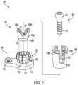
- FIG. 2shows an exploded perspective view of the bone anchor assembly 100'
- FIG. 3shows a cross-sectional view of the assembled bone anchor of FIG. 2
- the base 104'can be received within the receiver member 106' such that the toroid body 114' can extend distally from the receiver member and the base can rotate relative to the receiver.
- a saddle 105can be interposed between the base 104' and a spinal fixation element (not shown) received within the receiver member 106'.
- the head 112 of the shank 102can be received within the base 104', while the distal shaft 110 of the shank can extend distally from the base and, accordingly, from the receiver member 106', to engage with bone.
- the protruding portion 114'can be rotated relative to the receiver 106' and can be positioned such that the one or more auxiliary bone anchor openings 124' can be strategically located relative to the shank 102 and patient anatomy to provide the desired supplemental fixation.
- One or more auxiliary bone anchorscan be driven through the one or more auxiliary bone anchor openings in the protruding portion of the base to engage with bone and provide supplemental fixation support to that of the primary bone anchor.
- the lip 120' of the base 104'can be received within the groove 142' of the receiver member 106' such that the base 104' can rotate relative to the receiver member 106' about the axis A1.
- Relative axial movementi.e., movement along the axis A1
- the extension 118' and the lip 120'can include one or more deformable fingers 121 with gaps 123 therebetween.
- the fingers 121can compress radially inward when received within the lumen 136' of the receiver member 106', and can expand outward when the lip 120' aligns with the groove 142' of the receiver member. While the embodiments illustrated in FIGS. 1-3 show a connection feature of the base 104, 104' as the lip 120, 120' and a complementary connection feature of the receiver member 106, 106' as the groove 142, 142' alternative complementary connection features can be used and are within the scope of the present disclosure, so long as the connection between the base and the receiver member allows for relative rotation therebetween.
- a groove or one or more prongscan be formed on an interior distal surface of the receiver member 106 and can engage with a groove formed on an external surface of the extension 118.
- FIG. 3shows the base 104' and the saddle 105 received within the receiver member 106'. At least a portion of the extension 118' of the base 104' can be received within a distal portion of the lumen 136' of the receiver member 106' such that the toroid body 114' of the base extends distally from the distal surface of the receiver member.
- the lip 120' of the extension 118'can be deformable, and can compress radially inward during insertion of the extension into the receiver member 106'. The lip 120' can then expand to its initial state when the lip aligns with the groove 142' of the receiver member 106', as shown in FIG. 3 , and can retain the base 104' within the receiver member.
- a proximal facing surface of the toroid body 114'can contact a distal-facing surface of the receiver member 106'.
- a portion of the extension 118'can extend distally from the receiver member 106' such that the toroid body 114' does not contact the receiver member 106'.
- the wing 116'can extend from the toroid body 114' radially outward from the central axis A1, i.e., radially outward relative to the lumen 122 of the base 104'. In the assembled configuration, the wing 116', having at least one auxiliary bone anchor opening 124, can rotate with the base 104' relative to the receiver member 106'.
- the saddle 105can be received within the lumen 136' of the receiver member 106', with at least a portion of the saddle in contact with the base 104'.
- the saddle 105can have a proximal portion 105p, a distal portion 105d, and a lumen 107 extending therebetween.
- the saddle 105can include a pair of spaced apart arms 109A, 109B defining a U-shaped seat 111 that can receive the spinal fixation element, and a distal-facing surface 113 of the proximal portion 105p that can abut a proximal-facing surface of the base 104' and/or a portion of the proximal head 112 of the screw shank 102.
- the distal portion 105d of the saddle 105can be received within the extension 118' of the base 104' such that the distal portion of the saddle can extend into the lumen 122 of the base.
- the saddle 105can be positioned within the receiver member 106' and interposed between the base 104 and a spinal fixation element in the rod-receiving recess 140.
- the saddle 105can be inserted into the lumen 136 of the receiver member 106 such that the arms 109A, 109B deflect radially inward.
- the armscan expand radially outward to seat portions thereof within the groove 143, thereby retaining the saddle to the receiver member.
- Dimensions of the groove 143 and portions of the arms 109A, 109B configured to be received thereincan be set to allow for desired axial movement of the saddle 105 relative to the receiver member 106 when, e.g., varying forces exerted by the saddle on the shank 102.
- the saddle 105can compress a distal outer surface of the head of the shank 102 into direct, fixed engagement with a distal inner surface 119 of the base 104'.
- the head 112 of the shank 102can be received and retained within the base 104', i.e., within the lumen 122', while the distal shaft 110 of the shank can extend distally from the toroid body 114' of the base 104'.
- the shank 102can be inserted into the base 104' before or after inserting the base 104' into the receiver member 106'.
- the base 104'can rotate 360 degrees relative to the receiver 106'.
- FIG. 4shows a top view of a first position of the base 104' with respect to the receiver member 106', in which the wing 116' can extend to the left of the receiver, with respect to the illustrated view in FIG. 4 , at substantially a mid-line of the receiver arm 138A'.
- the base 104'can be rotated relative to the receiver 106' in either a clockwise or counter-clockwise direction, indicated by arrows 202 and 204, respectively.
- a usercan grasp the wing 116' or toroid body 114' and rotate the base 104' clockwise to place the wing 116' in a second position, for example the position shown in FIG. 5 , that is different from the first position.
- the bone anchor assembly 100can be assembled prior to implantation into a patient.
- the screw shank 102can be top-loaded into the base 104. More particularly, the screw shank 102 can be passed distally through the lumen 122 of the base 104 such that the shaft 110 of the screw shank can extend distally from the toroid body 114 of the base while the proximal head 112 of the screw shank can be received within the lumen 122 of the base 104.
- the screw shank 102can be bottom-loaded into the base 104.
- the base 104 with the shank 102 received thereincan be inserted into the receiver 106 such that the base can be rotated relative to the receiver. More particularly, the extension 118 can be inserted through the distal opening of the receiver 106 and can be moved proximally within the lumen 136 of the receiver until the lip 120 of the base 104 can be captured, e.g., within the groove 142 of the receiver 106. Alternatively, the base 104 can be coupled to the receiver 106 prior to inserting the shank 102 through the base 104. In such instances, the shank 102 can be moved distally through the lumen 136 of the receiver 106 and the lumen 122 of the base 104.
- the base 104 and the receiver member 106can be manufactured as a single component with the base rotatable relative to the receiver member 106 as described herein. As discussed above, with the base 104 connected with the receiver 106, the base, including the toroid body 114 and the wing 116, can rotate relative to, and independently of, the receiver 104 about the central axis A1.
- the shankWith the receiver member 106, the base 104, and the screw shank 102, i.e., the primary bone anchor, assembled, the shank can be driven into bone in accordance with standard surgical technique.
- the bone anchor assembly 100can be a polyaxial bone screw designed for posterior implantation in the pedicle or lateral mass of a vertebra.
- the wing 116 of the base 104With the shank 102 implanted into bone, the wing 116 of the base 104 can be rotated relative to the shank 102 and the receiver 106 to position the one or more auxiliary bone anchor openings 124 at a desired location.
- wing 116 and auxiliary bone anchor openings 124can be taken into consideration when positioning the wing 116 and auxiliary bone anchor openings 124 including, for example, placement of the shank 102, patient anatomy, other instrumentation, and surgical procedure requirements, such as, whether the bone into which the shank 102 engages is to be fused to one or more adjacent vertebrae.
- One or more auxiliary bone anchors 108can then be driven through the one or more corresponding auxiliary bone anchor openings 124 of the wing 116 into bone to supplement fixation of the bone anchor 100.
- one or more of the auxiliary bone anchors 108can be driven with an angled or biased trajectory relative to the central axis A1 of the bone anchor, the shank 102, and/or one or more other auxiliary bone anchor.
- a spinal rodcan be placed within the rod-receiving recess 140 of the receiver member 106 and can be secured within the receiver member with a closure, for example, a set screw.
- the one or more auxiliary bone anchors 108can be placed either before or after placement and/or securing of the spinal rod within the receiver member.
- the primary bone anchorcan be omitted and the user can rely solely on the one or more auxiliary fixation features to secure the bone anchor.
- Thiscan advantageously allow the position of the fixation to be completely offset from the receiver member, for example if an initially placed bone anchor needs to be removed due to improper positioning or inadequate purchase, or when the receiver member needs to be positioned over a location where a bone anchor cannot be inserted.
- auxiliary fixation members disclosed hereincan be implanted in the same surgical procedure as the bone anchor, receiver member, and spinal rod, or, in the case of revision surgery, during a subsequent surgical procedure.
- the embodiments of the inventionprovide enhanced fixation for a given surgical site, providing greater bone fixation strength at a given location without necessarily requiring moving the fixation to an additional vertebra or skipping/increasing the involved vertebral levels.
- the bone anchor assemblies disclosed herein and the various component parts thereofcan be constructed from any of a variety of known materials. Exemplary materials include those which are suitable for use in surgical applications, including metals such as stainless steel, titanium, or alloys thereof, polymers such as PEEK, ceramics, carbon fiber, and so forth.
- the various components of the devices disclosed hereincan be rigid or flexible. One or more components or portions of the device can be formed from a radiopaque material to facilitate visualization under fluoroscopy and other imaging techniques, or from a radiolucent material so as not to interfere with visualization of other structures. Exemplary radiolucent materials include carbon fiber and high-strength polymers.
- the method and devices described aboverelate to a spinal surgical application. While this is one contemplated use, the methods and devices of the present disclosure can be equally adapted for use in other areas of a patient's body, and can be used with any human or animal implant, in any of a variety of surgeries performed on humans or animals, and/or in fields unrelated to implants or surgery. As such, the devices described herein can be formed in a variety of sizes and materials appropriate for use in various areas of a patient's body. The systems and methods disclosed herein can be used in minimally-invasive surgery and/or open surgery.
Landscapes
- Health & Medical Sciences (AREA)
- Orthopedic Medicine & Surgery (AREA)
- Life Sciences & Earth Sciences (AREA)
- Surgery (AREA)
- Neurology (AREA)
- Heart & Thoracic Surgery (AREA)
- Engineering & Computer Science (AREA)
- Biomedical Technology (AREA)
- Nuclear Medicine, Radiotherapy & Molecular Imaging (AREA)
- Medical Informatics (AREA)
- Molecular Biology (AREA)
- Animal Behavior & Ethology (AREA)
- General Health & Medical Sciences (AREA)
- Public Health (AREA)
- Veterinary Medicine (AREA)
- Surgical Instruments (AREA)
- Connection Of Plates (AREA)
- Clamps And Clips (AREA)
Description
- Bone anchor assemblies with multiple bone engagement points are disclosed herein.
- Bone anchor assemblies can be used in orthopedic surgery to fix bone during healing, fusion, or other processes. In spinal surgery, for example, bone anchor assemblies can be used to secure a spinal fixation element to one or more vertebrae to rigidly or dynamically stabilize the spine. Bone anchor assemblies can also be used as an engagement point for manipulating bone (e.g., distracting, compressing, or rotating one vertebra with respect to another vertebra, reducing fractures in a long bone, and so forth).
- The integrity with which the bone anchor assembly engages the bone can affect the transfer of corrective biomechanical forces. While a great amount of care is exercised when placing bone anchor assemblies, it is common that a bone anchor assembly will be inserted in a compromised state. For example, the bone opening in which the assembly is disposed can be stripped (e.g., by driving the bone anchor assembly past its optimum holding position), the bone anchor assembly can be placed incorrectly (e.g., using an incorrect instrument maneuver such as an over-sized pilot hole), the bone anchor assembly can be placed outside of its intended trajectory (e.g., within a facet capsule or breached through a pedicle wall), or the bone anchor can be inserted into compromised bone (e.g., bone that is fractured, osteoporotic, diseased, or otherwise lacking in structural integrity).
- When the bone anchor assembly is in a compromised state, there can be sub-optimal purchase between the bone anchor assembly and the bone. The bone anchor assembly may feel unsecure to the surgeon, and it is possible that the bone anchor assembly could back out or become loosened over time. There are limited options for the surgeon when faced with these types of situations. In spinal surgery, for example, the surgeon can remove the bone anchor assembly and skip the vertebral level, though this can undesirably require expanding the surgical site to additional vertebral levels. The surgeon can remove and re-insert with a larger anchor, though this may not be an option when space for anchoring in the bone is limited. The surgeon can leave the compromised bone anchor assembly in place, which may be the safest alternative if the bone anchor assembly is in a safe location and attachment to the plate, rod, or other implant construct is definitive, as the additional compromised fixation may be better than removal.
- Even when a bone anchor assembly is placed in a non-compromised state, the geometry of traditional bone anchor assemblies can limit the flexibility with which the bone attachment point can be located with respect to a plate, rod, or other implant construct coupled to the bone anchor assembly.
US2019/290331 provides a bone anchor assembly according to the preamble of claim 1. - There is a continual need for improved bone anchor assemblies and related methods.
- The present invention is defined in claim 1 while preferred embodiments are set forth in the dependent claims.
- Associated surgical methods are also described herein to aid understanding the invention. These methods do not form part of the claimed invention.
- Bone anchor assemblies are disclosed herein that can provide for improved fixation as compared with traditional bone anchor assemblies.
- According to the invention, the assembly includes a multipoint eyelet component that is part of a bone anchor base. The eyelet component can be integrated into a receiver member assembly in a manner that allows positioning the eyelet at any desired position around a circumference of the receiver member. The eyelet component can accommodate one or more auxiliary bone anchors that augment the fixation of the assembly's primary bone anchor. Surgical methods using the bone anchor assemblies described herein are also disclosed.
- According to the invention, a bone anchor assembly includes a base, a receiver member, and a shank. The base includes a toroid body portion and a radial protrusion (e.g., an eyelet or wing) extending radially from the toroid, the radial protrusion having at least one auxiliary bone anchor opening configured to receive an auxiliary bone anchor. The receiver member has a proximal end, a distal end, a lumen extending from the proximal end to the distal end, and a rod-receiving recess. The shank has a head portion retained within the toroid body of the base and a bone engaging portion that extends distally from the base. The base is coupled to the receiver member such that the base is configured to rotate relative to the receiver member. The base further comprises an extension extending proximally from the toroid body portion, wherein the extension is received within the lumen of the receiver member.
- The devices described herein can have a number of additional features and/or variations, all of which are within the scope of the present disclosure. In some embodiments, for example, the toroid body of the base can extend distally from the receiver member. In some such embodiments, the extension can have a first connection feature and the receiver member can have a second connection feature. The first connection feature can be configured to engage with the second connection feature such that the base can be rotatably received within the receiver member. Further, in some embodiments, the first connection feature and the second connection feature can be configured such that relative axial movement between the base and the receiver member can be restricted when the first connection feature engages with the second connection feature. In some embodiments, the first connection feature can be a lip at a proximal end of the extension, and the second connection feature can be a groove in an inner surface of the receiver member. The groove of the receiver member can be distal to the rod-receiving recess.
- In some embodiments the bone anchor assembly can include a saddle disposed within the receiver member. The saddle can have a distal-facing surface that can contact a proximal-facing surface of the extension of the base when the base is disposed within the receiver member. In some embodiments, the at least one auxiliary bone anchor opening of the base can include a plurality of auxiliary bone anchor openings. A central lumen of the at least one auxiliary bone anchor opening can extend at a transverse angle relative to a central axis of the receiver member. The central lumen of the at least one auxiliary bone anchor opening can be angled in one of a caudal and a cephalad direction. In some embodiments, the central lumen of the at least one auxiliary bone anchor opening can be angled in one of a medial and a lateral direction.
- In another set of background information, useful for understanding the disclosure, a surgical method can include driving a shank portion of a bone anchor into a bone of a patient and rotating a base of a bone anchor assembly relative to a receiver member of the bone anchor assembly, the base having a radially protruding portion with at least one auxiliary bone anchor opening extending therethrough and the receiver member configured to receive a spinal fixation element. The method can include positioning the radially protruding portion of the bone anchor at a desired position relative to the shank portion and driving at least one auxiliary bone anchor through the at least one auxiliary bone anchor opening and into bone of the patient.
- In some background information, driving the at least one auxiliary bone anchor through the at least one auxiliary bone anchor opening and into bone of the patient can include driving the auxiliary bone anchor through the auxiliary bone anchor opening with an insertion trajectory that can be biased relative to at least one of a central axis of the receiver member and the shank to supplement fixation of the bone anchor within the bone. Rotating the base of the bone anchor assembly can include rotating the base about a central longitudinal axis of the receiver member.
- In some background information, the method can include placing a spinal rod within the receiver member and securing the spinal rod within the receiver member before driving the at least one auxiliary bone anchor into bone. In other embodiments, placing a spinal rod within the receiver member and securing the spinal rod within the receiver member can occur after driving the at least one auxiliary bone anchor into bone.
- The background information method can further include assembling the bone anchor by coupling the base to the receiver member such that the base is rotatable with respect to a central longitudinal axis of the receiver member and inserting the shank through the receiver member and the base such that a distal bone-engaging portion of the shank extends distally from the base and a head portion of the shank is received within the base. The shank can be polyaxially rotatable relative to the base.
- The embodiments of the present disclosure described above will be more fully understood from the following detailed description taken in conjunction with the accompanying drawings, in which:
FIG. 1 is an exploded perspective view of one embodiment of a bone anchor assembly of the present disclosure;FIG. 2 illustrates an exploded perspective view of another embodiment of a bone anchor assembly of the present disclosure;FIG. 3 is a cross-sectional view of the bone anchor assembly ofFIG. 2 ;FIG. 4 schematically illustrates a base of the bone anchor assembly ofFIG. 2 in a first position relative to a receiver of the bone anchor assembly ofFIG. 2 ; andFIG. 5 schematically illustrates the base of the bone anchor assembly ofFIG. 2 rotated to a second position relative to the receiver of the bone anchor assembly ofFIG. 2 .- Certain exemplary embodiments will now be described to provide an overall understanding of the principles of the structure and function of the assemblies described herein. Manufacture and use of the assemblies are also described herein, but not claimed. One or more of these embodiments are illustrated in the accompanying drawings.
- Bone anchor assemblies are disclosed herein that can provide or improved fixation as compared with traditional bone anchor assemblies. A bone anchor assembly of the present disclosure can include a primary screw shank to engage with bone, a base having a radially-extending protrusion (e.g., a protruding eyelet, wing, etc.) with at least one auxiliary bone anchor opening to receive an auxiliary bone anchor, and a receiver member for receiving a spinal fixation element. The base can couple with the receiver member such that the base can rotate relative to, and independently of, the receiver member and primary shank. In this manner, the base can be rotated to adjust the one or more auxiliary bone anchor openings positioning relative to the receiver member and bone anchor once the primary screw shank has engaged with bone, e.g., a vertebra, of a patient.
- The bone anchor assembly can be assembled by inserting the screw shank into the base such that a proximal head of the screw shank can be seated or otherwise retained within the base with a distal bone-engaging portion of the screw shank extending distally from the base. The base can be inserted into the receiver member and coupled therewith such that the base can rotate relative to the receiver. The screw shank can be driven into patient anatomy, e.g., a vertebra, and the base can be rotated freely about a longitudinal axis of the receiver member to position one or more auxiliary bone anchor openings on a protrusion (e.g., an eyelet, wing, etc.) of the base to provide for desired supplemental fixation in addition to the primary screw shank. One or more auxiliary bone anchors, also referred to herein as supplemental fixation screws, can then be inserted into the auxiliary bone anchor openings to provide the supplemental fixation. A spinal fixation rod can be placed and/or secured within the receiver member either before or after placement of the supplemental fixation screws. Accordingly, bone anchor assemblies of the present disclosure can provide supplemental fixation to a primary screw in a strategic and patient-specific manner, without requiring additional components beyond the bone anchor assembly.
FIG. 1 illustrates an exploded view of an embodiment of abone anchor assembly 100 in accordance with the present disclosure. As noted above, a bone anchor can sometimes be inserted in a compromised state. This can be undesirable, especially in instances in which there is limited bone area in which to install additional bone anchors. The illustratedbone anchor assembly 100 can allow for supplemental fixation of a primary bone anchor in a compact footprint, without necessarily requiring removal or re-insertion of the primary bone anchor. As shown, thebone anchor 100 can include aprimary bone anchor 102, also referred to as a primary screw shank, abase 104, areceiver member 106 for receiving a spinal fixation element (not shown), such as a spinal rod, to be coupled to the bone anchor, and one or more auxiliary bone anchors 108. A closure mechanism (not shown), such as a set screw, can capture a spinal fixation element within thereceiver member 106 and fix the spinal fixation element with respect to the receiver member. The spinal fixation element, e.g., the spinal rod, can either directly contact the receiver member 106 (or other component such asbase 104 and/orbone anchor 102, or can contact an intermediate element, e.g., asaddle 105, as shown, for example, inFIGS. 2 and3 . In use, the base 104 can be coupled to thereceiver member 106 such that the base can rotate relative to the receiver member about a central longitudinal axis A1 of the receiver member, while relative movement along the longitudinal axis A1 can be restricted or limited. One or more supplemental fixation screws 108 can be driven into bone through a corresponding one or more auxiliarybone anchor openings 124 of thebase 104, and can supplement fixation of thebone anchor 102 within patient anatomy.- The
primary screw shank 102 can include a distal threadedshaft 110 configured to engage bone and aproximal head 112. Theproximal head 112 can generally have the shape of a truncated sphere with a planar proximal surface and an approximately spherically-shaped distal surface. Theproximal head 112 of thescrew shank 102 can engage with a distal end of thebase 104, for example, in a ball and socket like arrangement in which theproximal head 112 can pivot relative to thebase 104. A distal surface of theproximal head 112 of theshank 102 and a mating surface within the distal end of the base 104 can have any shape that can facilitate this arrangement, including, for example, spherical, toroidal, conical, frustoconical, and any combination thereof. - The
distal shaft 110 of theshank 102 can be configured to engage bone and, in the illustrated embodiment, can include an external bone engaging thread. The thread form for thedistal shaft 110, including the number of threads, the pitch, the major and minor diameters, and the thread shape, can be selected to facilitate connection with bone. Exemplary thread forms are disclosed inU.S. Patent Application Publication No. 2011/0288599, filed on May 18, 2011 , and inU.S. Patent Application Publication No. 2013/0053901, filed on August 22, 2012 . - The base 104 can have a
toroid body portion 114 with a radially protruding portion (e.g., an eyelet or wing) 116 extending radially therefrom. Anextension 118 can extend proximally from thetoroid body 114. Theproximal extension 118 can include alip 120, or other connection feature, such as, for example, one or more prongs, a groove, etc., for engagement with a complimentary connection feature of thereceiver 106. In some embodiments theextension 118 and thelip 120 can be deformable. For example, thelip 120 can compress radially inward when thelip 120 is received within alumen 136 of thereceiver member 106, and can expand radially outward from a compressed position when thelip 120 aligns with agroove 142 of the receiver member. In this manner, thelip 120 of the base 104 can engage with thegroove 142 of thereceiver member 106 to retain thebase 104 within thereceiver member 106. In some embodiments thelip 120 and theextension 118 can be a deformable monolithic structure. In other embodiments, a connection feature, e.g., thelip 120, can be formed on or extend from thetoroid body 114 itself, and theproximal extension 118 can be omitted. - A
lumen 122 with a central longitudinal axis A1 can extend through thebase 104, and, more particularly, can extend through thetoroid body 114 and theproximal extension 118. Thescrew shank 102 can be inserted through thelumen 122 such that the distal threadedportion 110 extends distally from thetoroid body 114 while thehead portion 112 of thescrew shank 102 can be received within thetoroid body 114. In some embodiments, an interior surface of thetoroid body 114 can include features complementary to theproximal head 112 of thescrew shank 102 such that the screw shank can be retained within thetoroid body 114 and, in some embodiments, can move polyaxially relative to the toroid body. While a "top-down" assembly is described above, wherein thescrew shank 102 is passed distally through the base 104 until theproximal head 112 is received within thetoroid body 114 of the base, in other embodiments the assembly can be configured for "bottom loading," wherein thescrew shank 102 is passed proximally through the base 104 in order to seat theproximal head 112 into thetoroid body 114. This can be accomplished, for example, by forming thetoroid body 114 and/orproximal head 112 such that it can deform to allow passage of the proximal head into a recess of the toroid body. Examples of features permitting such coupling can include the use of elastically deformable materials, elastic fingers forming a collet or other gripping structure, etc. - The protruding portion or
wing 116 can extend from thetoroid body 114 and can form part of thebase 104. The protrudingportion 116 can extend radially outward from thetoroid body 114, i.e., away from the central longitudinal axis A1 of thelumen 122. An auxiliary bone anchor opening 124 can be formed in thewing 116. While asingle opening 124 is shown on thewing 116 ofFIG. 1 , in some embodiments, thewing 116 can include a plurality of auxiliarybone anchor openings 124. The auxiliary bone anchor opening 124 can be configured to receive anauxiliary fixation element 108. As shown inFIG. 1 , a central longitudinal axis A2 of theopening 124 can extend substantially parallel to the central longitudinal axis A1 of thelumen 122. In other embodiments, theopening 124 can extend with a biased or angled trajectory relative to the central axis A1 of thelumen 122. For example, the central axis A2 of theopening 124 can extend at an oblique angle relative to the central longitudinal axis A1 of thelumen 122. In this manner, anauxiliary bone anchor 108 can be received through the auxiliary bone anchor opening 124 and can be placed within patient anatomy with a caudal or cephalad trajectory, depending on placement of the protrudingportion 116 relative to the patient anatomy. Additionally, or alternatively, the central axis A2 of the opening 126 can extend radially inward towards the central axis A1 of theopening 122 or radially outward away from the central axis A1 of theopening 122. In embodiments with a plurality of auxiliarybone anchor openings 124 in the protrudingportion 116, each opening 124 can be angled or biased to have either the same or different trajectories. Further features and embodiments of an auxiliary bone anchor opening can be found inU.S. Patent Application Serial No. 16/583,233, filed on September 25, 2019 US 2021/0085375 A1 ). - In some embodiments, each auxiliary bone anchor opening 124 can include any of a number of features for accepting an
auxiliary bone anchor 108 at varying angles, such as, for example, conical, spherical, or parabolic threads. For example, as discussed inU.S. Patent Application Serial No. 16/583,233 with respect to, for example, FIGS. 2A-2M, theopening 124 can be at least partially threaded to receive a variable-angle locking screw 108 having a threadedproximal head 132. As shown inFIG. 1 , theopening 124 can have a plurality of columns ofthreads 128 spaced apart to define a plurality ofnon-threaded recesses 130. In this manner, the threads of theopening 124 can form an interlocking interface and mate withthreads 125 of thesupplemental fixation screw 108 to lock thescrew 108 therein. In one embodiment, the threads of theopening 124 can be conical threads. The columns ofthreads 128 can be arranged around an inner surface of theopening 124 for engagingthreads 132 on a head of a locking and/or a variable-angleauxiliary bone screw 108. Thesupplemental fixation screw 108 can thus be locked within the protrudingportion 116, and specifically within theopening 124, co-axially with the central axis A1 of the base 104 or at a selected angle within a range of selectable angles relative to the central axis of the base. For example, thescrew 108 can be inserted into theopening 124 along a trajectory A3 that can extend at a transverse angle relative to the central axis A2 of the opening. Theopening 124 can have any number of columns of threads 128 (e.g., two, three, four, etc.) to facilitate variable angle locking with thesupplemental fixation screw 108. Additionally, or alternatively, theopening 124 can include one or more additional locking components, such as a cam, and/or can facilitate locking with thescrew 108 through material deformation, e.g., splaying of the auxiliary bone anchor opening. - The
auxiliary bone anchor 108 can include features to facilitate this variable-angle locking, such as a proximal head that is at least partially spherical having a thread with a profile that follows the arc-shaped radius of curvature of the spherical portion of the head. The variable-angle capability of the interlocking interface (i.e., the screw/opening interface) can allow the user to place a locking auxiliary bone anchor into the bone at any angle defined within angulation limits, thus providing improved placement flexibility and eliminating or reducing the need to conform thewing 116 to a bone surface to achieve a desired insertion angle. Accordingly, theauxiliary bone anchor 108 can be driven into the bone with a diverging or converging longitudinal axis relative to theprimary bone anchor 102. In instances in which a plurality of bone anchors 108 can each be driven through an opening of the protrudingportion 116, the bone anchors 108 can be driven into the bone with diverging or converging longitudinal axes relative to each other and/or relative to theprimary bone anchor 102. Biased or angled trajectories of the auxiliary bone anchors 108 can provide improved resistance to pullout. A locking interface between an auxiliary bone anchor opening and an auxiliary bone anchor can increase stability and prevent the auxiliary bone anchor from backing out of the opening. - As described above, the auxiliary bone anchor opening 124 can include a locking interface with one or more locking features to lock a head of the auxiliary bone anchor within the
opening 124. In other embodiments, theopening 124 can have a lagging interface with the auxiliary bone anchor, in which the head of the auxiliary bone anchor does not independently lock relative to theopening 124. In some such embodiments, the interior surface of theopening 124 can be smooth or spherical, without threads or locking features. - The
receiver member 106 can have aproximal end 106p, a distal end 106d, and alumen 136 extending therebetween. Theproximal end 106p can have a pair of spaced apartarms recess 140 therebetween for receiving a spinal fixation element, e.g., a spinal rod. Each of thearms receiver member 106 to a free end. The outer surfaces of each of thearms receiver member 106 to instruments. For example, the outer surface of eacharm U.S. Patent No. 7,179,261, issued on February 20, 2007 . A closure mechanism, such as a set screw, (not shown) can be positioned between and can engage thearms receiver member 106 and fix the spinal fixation element with respect to the receiver member. For example, thearms internal threads 141 that can engage with external threads of the closure mechanism. - The distal end 106d of the
receiver member 106 can have a distal end surface which is generally annular in shape defining an opening through which at least a portion of thebase 104 and theshank 102 can extend. For example, theextension 118 of the base 104 can be inserted through the distal opening of thereceiver member 106 such that thelip 120 of the extension can engage with thegroove 142 of the receiver member and thetoroid body 114 of the base can extend distally from the receiver member. As described in detail with reference toFIGS. 2-4 , the base 104 can couple with thereceiver member 106 such that the base can be rotated relative to the receiver member about a central longitudinal axis of the receiver member. - In the assembled configuration of the
bone anchor assembly 100, a central longitudinal axis of thelumen 136 of thereceiver member 106 can be co-axial with the central longitudinal axis A1 of thelumen 122 of the base. The base 104 can couple with thereceiver member 106 such that the base 104 can rotate about the central axis A1 relative to the receiver member. In some embodiments, the base 104 can rotate 360 degrees about the central axis A1 relative to the receiver member in both a clockwise or counter-clockwise direction. Relative axial movement along the central axis A1 between the base 104 and thereceiver member 106, however, can be limited or restricted. Thereceiver member 106 can receive a spinal fixation element, such as a spinal rod (not shown), within the rod-receivingrecess 140 such that the spinal fixation element can extend transverse relative to the longitudinal axis A1. - The structure, assembly, and use of bone anchor assemblies of the present disclosure will now be described in greater detail with reference to the alternative embodiment of a bone anchor assembly 100' as shown in
FIGS. 2 and3 .FIG. 2 shows an exploded perspective view of the bone anchor assembly 100', andFIG. 3 shows a cross-sectional view of the assembled bone anchor ofFIG. 2 . In use, the base 104' can be received within the receiver member 106' such that the toroid body 114' can extend distally from the receiver member and the base can rotate relative to the receiver. Optionally, asaddle 105 can be interposed between the base 104' and a spinal fixation element (not shown) received within the receiver member 106'. Thehead 112 of theshank 102 can be received within the base 104', while thedistal shaft 110 of the shank can extend distally from the base and, accordingly, from the receiver member 106', to engage with bone. The protruding portion 114' can be rotated relative to the receiver 106' and can be positioned such that the one or more auxiliary bone anchor openings 124' can be strategically located relative to theshank 102 and patient anatomy to provide the desired supplemental fixation. One or more auxiliary bone anchors can be driven through the one or more auxiliary bone anchor openings in the protruding portion of the base to engage with bone and provide supplemental fixation support to that of the primary bone anchor. - The lip 120' of the base 104' can be received within the groove 142' of the receiver member 106' such that the base 104' can rotate relative to the receiver member 106' about the axis A1. Relative axial movement, i.e., movement along the axis A1, however, can be restricted, for example, by tolerance dimensions of the
groove 142 relative to the lip 120' and/or a length of the extension 118' of the base 104' along the direction of the axis A1. In some embodiments, the extension 118' and the lip 120' can include one or moredeformable fingers 121 withgaps 123 therebetween. Thefingers 121 can compress radially inward when received within the lumen 136' of the receiver member 106', and can expand outward when the lip 120' aligns with the groove 142' of the receiver member. While the embodiments illustrated inFIGS. 1-3 show a connection feature of thebase 104, 104' as thelip 120, 120' and a complementary connection feature of thereceiver member 106, 106' as thegroove 142, 142' alternative complementary connection features can be used and are within the scope of the present disclosure, so long as the connection between the base and the receiver member allows for relative rotation therebetween. By way of non-limiting example, a groove or one or more prongs can be formed on an interior distal surface of thereceiver member 106 and can engage with a groove formed on an external surface of theextension 118. FIG. 3 shows the base 104' and thesaddle 105 received within the receiver member 106'. At least a portion of the extension 118' of the base 104' can be received within a distal portion of the lumen 136' of the receiver member 106' such that the toroid body 114' of the base extends distally from the distal surface of the receiver member. As discussed above, the lip 120' of the extension 118' can be deformable, and can compress radially inward during insertion of the extension into the receiver member 106'. The lip 120' can then expand to its initial state when the lip aligns with the groove 142' of the receiver member 106', as shown inFIG. 3 , and can retain the base 104' within the receiver member. A proximal facing surface of the toroid body 114' can contact a distal-facing surface of the receiver member 106'. In other embodiments, a portion of the extension 118' can extend distally from the receiver member 106' such that the toroid body 114' does not contact the receiver member 106'. As described above, the wing 116' can extend from the toroid body 114' radially outward from the central axis A1, i.e., radially outward relative to thelumen 122 of the base 104'. In the assembled configuration, the wing 116', having at least one auxiliary bone anchor opening 124, can rotate with the base 104' relative to the receiver member 106'.- The
saddle 105 can be received within the lumen 136' of the receiver member 106', with at least a portion of the saddle in contact with the base 104'. Thesaddle 105 can have aproximal portion 105p, adistal portion 105d, and alumen 107 extending therebetween. Thesaddle 105 can include a pair of spaced apartarms U-shaped seat 111 that can receive the spinal fixation element, and a distal-facingsurface 113 of theproximal portion 105p that can abut a proximal-facing surface of the base 104' and/or a portion of theproximal head 112 of thescrew shank 102. Thedistal portion 105d of thesaddle 105 can be received within the extension 118' of the base 104' such that the distal portion of the saddle can extend into thelumen 122 of the base. Thesaddle 105 can be positioned within the receiver member 106' and interposed between the base 104 and a spinal fixation element in the rod-receivingrecess 140. For example, thesaddle 105 can be inserted into thelumen 136 of thereceiver member 106 such that thearms saddle 105 advances to a position where a distal portion of thearms groove 143 formed in thereceiver member 106, the arms can expand radially outward to seat portions thereof within thegroove 143, thereby retaining the saddle to the receiver member. Dimensions of thegroove 143 and portions of thearms saddle 105 relative to thereceiver member 106 when, e.g., varying forces exerted by the saddle on theshank 102. More particularly, with theproximal head 112 of theshank 102 received within the base 104', thesaddle 105 can compress a distal outer surface of the head of theshank 102 into direct, fixed engagement with a distalinner surface 119 of the base 104'. Thehead 112 of theshank 102 can be received and retained within the base 104', i.e., within the lumen 122', while thedistal shaft 110 of the shank can extend distally from the toroid body 114' of the base 104'. Theshank 102 can be inserted into the base 104' before or after inserting the base 104' into the receiver member 106'. - In the assembled configuration, the base 104' can rotate 360 degrees relative to the receiver 106'. For example,
FIG. 4 shows a top view of a first position of the base 104' with respect to the receiver member 106', in which the wing 116' can extend to the left of the receiver, with respect to the illustrated view inFIG. 4 , at substantially a mid-line of thereceiver arm 138A'. The base 104' can be rotated relative to the receiver 106' in either a clockwise or counter-clockwise direction, indicated byarrows FIG. 5 , that is different from the first position. - One example of a method of use of the
bone anchor assembly 100 will now be described. Thebone anchor assembly 100 can be assembled prior to implantation into a patient. Thescrew shank 102 can be top-loaded into thebase 104. More particularly, thescrew shank 102 can be passed distally through thelumen 122 of the base 104 such that theshaft 110 of the screw shank can extend distally from thetoroid body 114 of the base while theproximal head 112 of the screw shank can be received within thelumen 122 of thebase 104. Alternatively, in some examples, thescrew shank 102 can be bottom-loaded into thebase 104. - The base 104 with the
shank 102 received therein can be inserted into thereceiver 106 such that the base can be rotated relative to the receiver. More particularly, theextension 118 can be inserted through the distal opening of thereceiver 106 and can be moved proximally within thelumen 136 of the receiver until thelip 120 of the base 104 can be captured, e.g., within thegroove 142 of thereceiver 106. Alternatively, the base 104 can be coupled to thereceiver 106 prior to inserting theshank 102 through thebase 104. In such instances, theshank 102 can be moved distally through thelumen 136 of thereceiver 106 and thelumen 122 of thebase 104. In some embodiments, thebase 104 and thereceiver member 106 can be manufactured as a single component with the base rotatable relative to thereceiver member 106 as described herein. As discussed above, with the base 104 connected with thereceiver 106, the base, including thetoroid body 114 and thewing 116, can rotate relative to, and independently of, thereceiver 104 about the central axis A1. - With the
receiver member 106, thebase 104, and thescrew shank 102, i.e., the primary bone anchor, assembled, the shank can be driven into bone in accordance with standard surgical technique. For example, thebone anchor assembly 100 can be a polyaxial bone screw designed for posterior implantation in the pedicle or lateral mass of a vertebra. With theshank 102 implanted into bone, thewing 116 of the base 104 can be rotated relative to theshank 102 and thereceiver 106 to position the one or more auxiliarybone anchor openings 124 at a desired location. Various factors can be taken into consideration when positioning thewing 116 and auxiliarybone anchor openings 124 including, for example, placement of theshank 102, patient anatomy, other instrumentation, and surgical procedure requirements, such as, whether the bone into which theshank 102 engages is to be fused to one or more adjacent vertebrae. - One or more auxiliary bone anchors 108 can then be driven through the one or more corresponding auxiliary
bone anchor openings 124 of thewing 116 into bone to supplement fixation of thebone anchor 100. As discussed in detail above, one or more of the auxiliary bone anchors 108 can be driven with an angled or biased trajectory relative to the central axis A1 of the bone anchor, theshank 102, and/or one or more other auxiliary bone anchor. A spinal rod can be placed within the rod-receivingrecess 140 of thereceiver member 106 and can be secured within the receiver member with a closure, for example, a set screw. The one or more auxiliary bone anchors 108 can be placed either before or after placement and/or securing of the spinal rod within the receiver member. - In examples, the primary bone anchor can be omitted and the user can rely solely on the one or more auxiliary fixation features to secure the bone anchor. This can advantageously allow the position of the fixation to be completely offset from the receiver member, for example if an initially placed bone anchor needs to be removed due to improper positioning or inadequate purchase, or when the receiver member needs to be positioned over a location where a bone anchor cannot be inserted.
- While the methods illustrated and described herein involve a bone anchor placed in the pedicle or lateral mass of vertebral bone, it will be appreciated that the systems and methods herein can be used in any bone, in non-bone tissue, or in non-living or non-tissue objects.
- The auxiliary fixation members disclosed herein can be implanted in the same surgical procedure as the bone anchor, receiver member, and spinal rod, or, in the case of revision surgery, during a subsequent surgical procedure.
- It should be noted that any ordering of method steps (not claimed) expressed or implied in the description above or in the accompanying drawings is not to be construed as limiting the disclosed methods to performing the steps in that order. Rather, the various steps of each of the methods disclosed herein can be performed in any of a variety of sequences. In addition, as the described methods are merely exemplary, various other methods that include additional steps or include fewer steps are also within the scope of the present disclosure.
- As evident from the foregoing, the embodiments of the invention provide enhanced fixation for a given surgical site, providing greater bone fixation strength at a given location without necessarily requiring moving the fixation to an additional vertebra or skipping/increasing the involved vertebral levels.
- The bone anchor assemblies disclosed herein and the various component parts thereof can be constructed from any of a variety of known materials. Exemplary materials include those which are suitable for use in surgical applications, including metals such as stainless steel, titanium, or alloys thereof, polymers such as PEEK, ceramics, carbon fiber, and so forth. The various components of the devices disclosed herein can be rigid or flexible. One or more components or portions of the device can be formed from a radiopaque material to facilitate visualization under fluoroscopy and other imaging techniques, or from a radiolucent material so as not to interfere with visualization of other structures. Exemplary radiolucent materials include carbon fiber and high-strength polymers.
- The method and devices described above relate to a spinal surgical application. While this is one contemplated use, the methods and devices of the present disclosure can be equally adapted for use in other areas of a patient's body, and can be used with any human or animal implant, in any of a variety of surgeries performed on humans or animals, and/or in fields unrelated to implants or surgery. As such, the devices described herein can be formed in a variety of sizes and materials appropriate for use in various areas of a patient's body. The systems and methods disclosed herein can be used in minimally-invasive surgery and/or open surgery.
- Specific embodiments are described above. The present invention is defined by the claims.
Claims (11)
- A bone anchor assembly [100], comprising:a base [104] having a toroid body portion [114] and a radially-extending portion [116] including at least one auxiliary bone anchor opening [124] configured to receive an auxiliary bone anchor [108];a receiver member [106] having a proximal end [106p], a distal end [106d], with a lumen [136] extending therebetween, and a rod-receiving recess [140]; anda shank [102] having a head portion [112] and a bone engaging portion [110] that extends distally from the base [104];wherein the base [104] is coupled to the receiver member [106] such that the base [104] is configured to rotate relative to the receiver member [106];characterized in that:the shank [102] has the head portion [112] retained within the toroid body portion [114];the base [104] further comprises an extension [118] extending proximally from the toroid body portion [114]; andwherein, the extension [118] is received within the lumen [136] of the receiver member [106].
- The bone anchor assembly [100] of claim 1, wherein the toroid body portion [114] of the base [104] extends distally from the receiver member [106].
- The bone anchor assembly [100] of claim 1, wherein the extension of the base [104] has a first connection feature [120] and the receiver member [106] has a second connection feature [142],
wherein the first connection feature [120] is configured to engage the second connection feature [142] such that the base [104] is rotatably received within the receiver member [106]. - The bone anchor assembly [100] of claim 3, wherein the first connection feature [120] and the second connection feature [142] are configured such that relative axial movement between the base [104] and the receiver member [106] is restricted when the first connection feature [120] engages with the second connection feature [142].
- The bone anchor assembly [100] of claim 3, wherein the first connection feature [120] is a lip [120] at a proximal end of the extension [118] and the second connection feature [142] is a groove [142] in an inner surface of the receiver member [106].
- The bone anchor assembly [100] of claim 5, wherein the groove [142] of the receiver member [204] is distal to the rod-receiving recess [140].
- The bone anchor assembly [100] of claim 1, further comprising a saddle [105] disposed within the receiver member [106], the saddle [105] having a distal-facing surface configured to contact a proximal-facing surface of the extension disposed within the receiver member [106].
- The bone anchor assembly [100] of claim 1, wherein the at least one auxiliary bone anchor opening [124] of the radially-extending portion [116] further comprises a plurality of auxiliary bone anchor openings [124].
- The bone anchor assembly [100] of claim 1, wherein a central lumen [122] of the at least one auxiliary bone anchor opening [124] extends at a transverse angle relative to a central axis of the receiver member [106].
- The bone anchor assembly [100] of claim 9, wherein the central lumen [122] of the at least one auxiliary bone anchor opening [124] is angled in one of a caudal and cephalad direction.
- The bone anchor assembly [100] of claim 9, wherein the central lumen [122] of the at least one auxiliary bone anchor opening [124] is angled in one of a medial and a lateral direction.
Applications Claiming Priority (2)
| Application Number | Priority Date | Filing Date | Title |
|---|---|---|---|
| US202062976766P | 2020-02-14 | 2020-02-14 | |
| PCT/EP2021/052709WO2021160518A1 (en) | 2020-02-14 | 2021-02-04 | Integrated multipoint fixation screw |
Publications (2)
| Publication Number | Publication Date |
|---|---|
| EP4103083A1 EP4103083A1 (en) | 2022-12-21 |
| EP4103083B1true EP4103083B1 (en) | 2024-10-23 |
Family
ID=74591957
Family Applications (1)
| Application Number | Title | Priority Date | Filing Date |
|---|---|---|---|
| EP21704724.0AActiveEP4103083B1 (en) | 2020-02-14 | 2021-02-04 | Integrated multipoint fixation screw |
Country Status (6)
| Country | Link |
|---|---|
| US (3) | US11304728B2 (en) |
| EP (1) | EP4103083B1 (en) |
| JP (1) | JP7676711B2 (en) |
| CN (1) | CN115087404A (en) |
| AU (1) | AU2021220225A1 (en) |
| WO (1) | WO2021160518A1 (en) |
Families Citing this family (8)
| Publication number | Priority date | Publication date | Assignee | Title |
|---|---|---|---|---|
| US9579123B2 (en)* | 2014-09-19 | 2017-02-28 | Globus Medical, Inc. | Orthopedic stabilization devices and methods for installation thereof |
| US9962192B2 (en) | 2016-03-17 | 2018-05-08 | Medos International Sarl | Multipoint fixation implants |
| US10898232B2 (en) | 2018-03-20 | 2021-01-26 | Medos International Sàrl | Multipoint fixation implants and related methods |
| WO2021034664A1 (en)* | 2019-08-14 | 2021-02-25 | K2M, Inc. | Pedicle fixation system |
| US11426210B2 (en) | 2019-09-25 | 2022-08-30 | Medos International Sàrl | Multipoint angled fixation implants for multiple screws and related methods |
| EP4103083B1 (en) | 2020-02-14 | 2024-10-23 | Medos International Sàrl | Integrated multipoint fixation screw |
| US20220183722A1 (en)* | 2020-12-10 | 2022-06-16 | Sanjay Amarasinghe | Pedicle tract stabilization system |
| JP2025529435A (en) | 2022-09-13 | 2025-09-04 | メドス・インターナショナル・エスエイアールエル | Modular Connector Assembly |
Family Cites Families (116)
| Publication number | Priority date | Publication date | Assignee | Title |
|---|---|---|---|---|
| FR2657774B1 (en) | 1990-02-08 | 1992-05-22 | Sofamor | SACRED TAKING SHOE FOR A SPINAL OSTEOSYNTHESIS DEVICE. |
| FR2658413B1 (en) | 1990-02-19 | 1997-01-03 | Sofamor | OSTEOSYNTHESIS DEVICE FOR THE CORRECTION OF SPINAL DEVIATIONS. |
| US5039265A (en) | 1990-02-28 | 1991-08-13 | Vsi Corporation | Lightweight fastener |
| DE9202745U1 (en) | 1992-03-02 | 1992-04-30 | Howmedica Gmbh, 2314 Schoenkirchen | Device for bracing vertebrae of the human spine |
| US5470333A (en) | 1993-03-11 | 1995-11-28 | Danek Medical, Inc. | System for stabilizing the cervical and the lumbar region of the spine |
| US5582612A (en) | 1995-05-01 | 1996-12-10 | Lin; Chih-I | Vertebral fixing and retrieving device having centrally two fixation |
| US5735852A (en) | 1995-05-22 | 1998-04-07 | Synthes (U.S.A.) | Clamp jaw for a spinal affixation device |
| EP0873090A1 (en)* | 1995-12-22 | 1998-10-28 | Ohio Medical Instrument Company, Inc. | Spinal fixation device with laterally attachable connectors |
| US6010503A (en)* | 1998-04-03 | 2000-01-04 | Spinal Innovations, Llc | Locking mechanism |
| CA2330705A1 (en) | 1998-04-29 | 1999-11-04 | Dimso (Distribution Medicale Du Sud-Ouest) | Backbone osteosynthesis system for anterior fixing |
| FR2780631B1 (en)* | 1998-07-06 | 2000-09-29 | Dimso Sa | SPINAL OSTEOSYNTHESIS DEVICE FOR ANTERIOR FIXATION WITH PLATE |
| US6342055B1 (en) | 1999-04-29 | 2002-01-29 | Theken Surgical Llc | Bone fixation system |
| JP3383257B2 (en) | 2000-03-10 | 2003-03-04 | 株式会社ロバート・リード商会 | Rod fixing device |
| JP2002000611A (en) | 2000-05-12 | 2002-01-08 | Sulzer Orthopedics Ltd | Bone screw to be joined with the bone plate |
| US6524315B1 (en) | 2000-08-08 | 2003-02-25 | Depuy Acromed, Inc. | Orthopaedic rod/plate locking mechanism |
| DE10055888C1 (en) | 2000-11-10 | 2002-04-25 | Biedermann Motech Gmbh | Bone screw, has connector rod receiving part with unsymmetrically arranged end bores |
| US6974460B2 (en) | 2001-09-14 | 2005-12-13 | Stryker Spine | Biased angulation bone fixation assembly |
| US20060142765A9 (en) | 2001-10-15 | 2006-06-29 | Dixon Robert A | Vertebral implant for bone fixation or interbody use |
| US6682530B2 (en)* | 2002-01-14 | 2004-01-27 | Robert A Dixon | Dynamized vertebral stabilizer using an outrigger implant |
| US7232441B2 (en) | 2002-02-13 | 2007-06-19 | Cross Medicalproducts, Inc. | Occipital plate and rod system |
| JP4307388B2 (en) | 2002-12-06 | 2009-08-05 | ジンテーズ ゲゼルシャフト ミト ベシュレンクテル ハフツング | Bone stabilization device |
| US7608096B2 (en) | 2003-03-10 | 2009-10-27 | Warsaw Orthopedic, Inc. | Posterior pedicle screw and plate system and methods |
| US7776076B2 (en) | 2004-05-11 | 2010-08-17 | Synthes Usa, Llc | Bone plate |
| US7074238B2 (en) | 2003-07-08 | 2006-07-11 | Archus Orthopedics, Inc. | Prostheses, tools and methods for replacement of natural facet joints with artificial facet joint surfaces |
| DE20321551U1 (en) | 2003-08-26 | 2007-12-27 | Synthes Gmbh | bone plate |
| US8167917B2 (en) | 2003-09-24 | 2012-05-01 | Spinefrontier Lls | Apparatus and method for spine fixation |
| US7179261B2 (en) | 2003-12-16 | 2007-02-20 | Depuy Spine, Inc. | Percutaneous access devices and bone anchor assemblies |
| EP1708629A4 (en) | 2004-01-08 | 2011-08-17 | David Mark Allison | Bone fixing device |
| US7637928B2 (en) | 2004-01-26 | 2009-12-29 | Synthes Usa, Llc | Variable angle locked bone fixation system |
| US8574268B2 (en) | 2004-01-26 | 2013-11-05 | DePuy Synthes Product, LLC | Highly-versatile variable-angle bone plate system |
| CA2557975A1 (en) | 2004-03-23 | 2005-10-06 | Warsaw Orthopedic, Inc. | Device and method for dynamic spinal fixation for correction of spinal deformities |
| US7645294B2 (en) | 2004-03-31 | 2010-01-12 | Depuy Spine, Inc. | Head-to-head connector spinal fixation system |
| US7717939B2 (en) | 2004-03-31 | 2010-05-18 | Depuy Spine, Inc. | Rod attachment for head to head cross connector |
| EP1758511A4 (en) | 2004-06-14 | 2008-12-03 | M S Abdou | Occipital fixation system and method of use |
| US20060195089A1 (en) | 2005-02-03 | 2006-08-31 | Lehuec Jean-Charles | Spinal plating and intervertebral support systems and methods |
| US8496686B2 (en) | 2005-03-22 | 2013-07-30 | Gmedelaware 2 Llc | Minimally invasive spine restoration systems, devices, methods and kits |
| US7811310B2 (en) | 2005-05-04 | 2010-10-12 | Spinefrontier, Inc | Multistage spinal fixation locking mechanism |
| US8388661B2 (en) | 2005-08-18 | 2013-03-05 | Synthes Usa, Llc | Rod connector for attaching a bone anchor to a support rod and implantation instrument therefor |
| DE102005044532A1 (en) | 2005-09-16 | 2007-04-05 | Ulrich Gmbh & Co. Kg | Ventral plate |
| US7695500B2 (en) | 2006-03-10 | 2010-04-13 | Custom Spine, Inc. | Polyaxial occipital plate |
| US8025681B2 (en) | 2006-03-29 | 2011-09-27 | Theken Spine, Llc | Dynamic motion spinal stabilization system |
| US20070233062A1 (en) | 2006-04-04 | 2007-10-04 | Amedica Corporation | Pedicle screw system with offset stabilizer rod |
| US8979903B2 (en) | 2006-04-26 | 2015-03-17 | Warsaw Orthopedic, Inc. | Revision fixation plate and method of use |
| US20080021454A1 (en)* | 2006-07-21 | 2008-01-24 | Depuy Spine, Inc. | Sacral or iliac connector |
| US7892260B2 (en)* | 2006-10-06 | 2011-02-22 | Depuy Spine, Inc. | Unilateral placement |
| US7976567B2 (en) | 2006-10-18 | 2011-07-12 | Warsaw Orthopedic, Inc. | Orthopedic revision connector |
| US7699876B2 (en)* | 2006-11-08 | 2010-04-20 | Ebi, Llc | Multi-axial bone fixation apparatus |
| US20080183217A1 (en) | 2006-11-29 | 2008-07-31 | Glaser John A | Posterior Vertebra Locking Plate |
| US8828061B2 (en) | 2007-03-19 | 2014-09-09 | Us Spine, Inc. | Vertebral stabilization devices and associated surgical methods |
| US8353937B2 (en) | 2007-05-22 | 2013-01-15 | Warsaw Orthopedic, Inc. | Spinal stabilization systems and methods |
| CA2694010C (en) | 2007-07-19 | 2015-04-21 | Synthes Usa, Llc | Clamps used for interconnecting a bone anchor to a rod |
| AU2008318657A1 (en) | 2007-10-30 | 2009-05-07 | Synthes Gmbh | Variable angle locked bone plate |
| US20090125067A1 (en) | 2007-11-08 | 2009-05-14 | Depuy Spine, Inc. | In-line occipital plate and method of use |
| CN101854873B (en) | 2007-11-13 | 2013-03-13 | 新特斯有限责任公司 | Periprosthetic fracture repair |
| WO2009073614A2 (en) | 2007-11-29 | 2009-06-11 | University Of South Florida | Apparatus for occipito-cervical fixation enabling supplemental occipital bone fixation |
| EP2249717B1 (en) | 2008-01-14 | 2015-02-25 | K2M, Inc. | Spinal fixation device |
| US20090248077A1 (en) | 2008-03-31 | 2009-10-01 | Derrick William Johns | Hybrid dynamic stabilization |
| US8551144B2 (en) | 2008-04-22 | 2013-10-08 | Collab Comlo, LLC | Bone plate system configurable as static or dynamic implant |
| US8303631B2 (en) | 2008-06-20 | 2012-11-06 | Neil Duggal | Systems and methods for posterior dynamic stabilization |
| US20110184470A1 (en) | 2008-08-07 | 2011-07-28 | K2M, Inc. | Bone screw assembly |
| US8226695B2 (en) | 2008-10-10 | 2012-07-24 | K2M, Inc. | Occipital plate for cervical fixation |
| US20100094358A1 (en)* | 2008-10-10 | 2010-04-15 | K2M, Inc. | Spinal staple |
| EP2745789B1 (en) | 2008-10-30 | 2017-04-19 | Depuy Spine Inc. | Systems for delivering bone cement to a bone anchor |
| JP5759900B2 (en) | 2008-12-05 | 2015-08-05 | ジンテス ゲゼルシャフト ミット ベシュレンクテル ハフツング | Anchor-in-anchor system for use in bone fixation |
| US8506567B2 (en) | 2009-02-04 | 2013-08-13 | Lanx, Inc. | Occipital plate fixation system |
| DE102009032034A1 (en) | 2009-06-26 | 2010-12-30 | Aesculap Ag | Surgical bone anchoring device and spine fixation system |
| US8758346B2 (en) | 2009-09-14 | 2014-06-24 | DePuy Synthes Products, LLC | Variable angle compression plate |
| FR2951064B1 (en) | 2009-10-09 | 2011-12-09 | Spineway | PLATE FOR SPINAL OSTEOSYNTHESIS DEVICE BY ANTERIOR |
| US8449578B2 (en) | 2009-11-09 | 2013-05-28 | Ebi, Llc | Multiplanar bone anchor system |
| US20110230920A1 (en) | 2010-03-19 | 2011-09-22 | K2M, Inc. | Spinal fixation apparatus and methods |
| JP5797748B2 (en) | 2010-05-19 | 2015-10-21 | デピュイ・シンセス・プロダクツ・インコーポレイテッド | Bone anchor |
| US20120010658A1 (en) | 2010-07-08 | 2012-01-12 | X-Spine Systems, Inc. | Spinal stabilization system utilizing screw and external facet and/or lamina fixation |
| GB2483531A (en)* | 2010-09-13 | 2012-03-14 | Facetmed Ltd | Spinal fixation system |
| EP2659845A1 (en) | 2010-12-27 | 2013-11-06 | Biedermann Technologies GmbH & Co. KG | Polyaxial bone anchoring device |
| US8672978B2 (en) | 2011-03-04 | 2014-03-18 | Zimmer Spine, Inc. | Transverse connector |
| US9585697B2 (en) | 2011-04-01 | 2017-03-07 | Rebecca Elizabeth Stachniak | Posterior stabilization systems and methods |
| RU2605147C2 (en) | 2011-04-01 | 2016-12-20 | Зинтес Гмбх | System for posterior spinal fixation with plate |
| JP6017553B2 (en) | 2011-06-17 | 2016-11-02 | ビーダーマン・テクノロジーズ・ゲゼルシャフト・ミット・ベシュレンクテル・ハフツング・ウント・コンパニー・コマンディートゲゼルシャフトBiedermann Technologies Gmbh & Co. Kg | Modular bone plate and members of the modular bone plate |
| WO2013022944A1 (en) | 2011-08-08 | 2013-02-14 | Revivo Medical, Llc | Dynamic spinal fixation system, method of use, and spinal fixation system attachment portions |
| US9247962B2 (en) | 2011-08-15 | 2016-02-02 | K2M, Inc. | Laminar hook insertion device |
| US9155580B2 (en) | 2011-08-25 | 2015-10-13 | Medos International Sarl | Multi-threaded cannulated bone anchors |
| US10226284B2 (en) | 2011-09-01 | 2019-03-12 | Globus Medical, Inc. | Laminoplasty plates, systems, and devices, and methods relating to the same |
| US20130085534A1 (en)* | 2011-09-30 | 2013-04-04 | Nicolas Hainard | Connectors for a secondary bone anchor |
| US20130096618A1 (en) | 2011-10-14 | 2013-04-18 | Thibault Chandanson | Bone anchor assemblies |
| US20130110163A1 (en) | 2011-10-28 | 2013-05-02 | Warsaw Orthopedic, Inc. | Attachment mechanism for material and bone |
| US8556942B2 (en) | 2011-12-30 | 2013-10-15 | Blackstone Medical, Inc. | Occipito-cervical fixation assembly and method for constructing same |
| US9060815B1 (en)* | 2012-03-08 | 2015-06-23 | Nuvasive, Inc. | Systems and methods for performing spine surgery |
| CN104519812B (en) | 2012-03-28 | 2018-04-10 | 费瑟特-链接公司 | The reinforcing implant for vertebral plate with cantilevered bridgeware |
| US20130261673A1 (en) | 2012-03-28 | 2013-10-03 | John Riley Hawkins | Quad anchor lateral vertebral body fixation plates |
| US8439924B1 (en) | 2012-04-02 | 2013-05-14 | Warsaw Orthopedic, Inc. | Spinal implant system and method |
| US10405893B2 (en)* | 2012-07-12 | 2019-09-10 | DePuy Synthes Products, Inc. | Device, kit and method for correction of spinal deformity |
| US20140052183A1 (en) | 2012-08-10 | 2014-02-20 | FreeseTEC Corporation | Posterior Spine Attachment Device for Hardware and Paraspinal Musculature |
| US9198767B2 (en) | 2012-08-28 | 2015-12-01 | Samy Abdou | Devices and methods for spinal stabilization and instrumentation |
| EP2964116A4 (en)* | 2013-03-08 | 2016-11-23 | Anand K Agarwal | Pedicle screw assembly |
| US20150012042A1 (en) | 2013-07-04 | 2015-01-08 | Institute for Musculoskeletal Science and Education, Ltd. | Orthopedic implantation device |
| US9566092B2 (en)* | 2013-10-29 | 2017-02-14 | Roger P. Jackson | Cervical bone anchor with collet retainer and outer locking sleeve |
| EP2873384B1 (en) | 2013-11-14 | 2016-10-05 | Biedermann Technologies GmbH & Co. KG | Bone anchor and bone anchoring assembly comprising the same |
| WO2015142320A1 (en) | 2014-03-18 | 2015-09-24 | Empire Technology Development Llc | Orthopedic stiffening device |
| US9855087B2 (en) | 2014-08-04 | 2018-01-02 | DePuy Synthes Products, LLC | Methods and devices for spinal screw insertion |
| US20160095637A1 (en) | 2014-10-05 | 2016-04-07 | Nexxt Spine, LLC | Locking mechanism for a cervical fixation plate |
| US9872711B2 (en)* | 2014-10-21 | 2018-01-23 | Warsaw Orthopedic. Inc. | Spinal implant system and method |
| US10172650B2 (en) | 2014-10-21 | 2019-01-08 | Warsaw Orthopedic, Inc. | Spinal implant system and method |
| US9649133B2 (en) | 2014-11-11 | 2017-05-16 | Intrepid Orthopedics | Supplemental fixation screw |
| FR3040285B1 (en) | 2015-08-31 | 2017-09-15 | Bpath | VERTEBRAL IMPLANT, METHOD FOR SETTING SUCH IMPLANT AND TOOL FOR IMPLANT PLACEMENT |
| US9962192B2 (en) | 2016-03-17 | 2018-05-08 | Medos International Sarl | Multipoint fixation implants |
| TWI727050B (en)* | 2016-05-26 | 2021-05-11 | 吳孟晃 | Spinal screw fixation device |
| US10786285B2 (en) | 2016-06-06 | 2020-09-29 | Stryker European Holdings I, Llc | Paraxial revision rod-to-rod connector |
| US10238432B2 (en) | 2017-02-10 | 2019-03-26 | Medos International Sàrl | Tandem rod connectors and related methods |
| US10966762B2 (en) | 2017-12-15 | 2021-04-06 | Medos International Sarl | Unilateral implant holders and related methods |
| US11344337B2 (en) | 2018-02-19 | 2022-05-31 | Zimmer Biomet Spine, Inc. | Systems for attenuation of increased spinal flexion loads post-fusion and associated methods |
| US10898232B2 (en) | 2018-03-20 | 2021-01-26 | Medos International Sàrl | Multipoint fixation implants and related methods |
| US11559333B2 (en)* | 2019-01-21 | 2023-01-24 | Zimmer Biomet Spine, Inc. | Bone anchor |
| US10568674B1 (en) | 2019-01-24 | 2020-02-25 | Syberspine Limited | Pedicle screws with integrated anchor for retaining artificial ligament tape used for posterior ligament reconstruction |
| CN110338894B (en)* | 2019-06-04 | 2023-05-09 | 迪恩医疗科技有限公司 | Pedicle screw capable of being fixed by double screws |
| US11426210B2 (en)* | 2019-09-25 | 2022-08-30 | Medos International Sàrl | Multipoint angled fixation implants for multiple screws and related methods |
| EP4103083B1 (en)* | 2020-02-14 | 2024-10-23 | Medos International Sàrl | Integrated multipoint fixation screw |
- 2021
- 2021-02-04EPEP21704724.0Apatent/EP4103083B1/enactiveActive
- 2021-02-04AUAU2021220225Apatent/AU2021220225A1/ennot_activeAbandoned
- 2021-02-04JPJP2022548944Apatent/JP7676711B2/enactiveActive
- 2021-02-04WOPCT/EP2021/052709patent/WO2021160518A1/ennot_activeCeased
- 2021-02-04CNCN202180014255.1Apatent/CN115087404A/enactivePending
- 2021-02-12USUS17/174,456patent/US11304728B2/enactiveActive
- 2022
- 2022-03-14USUS17/694,645patent/US12185980B2/enactiveActive
- 2024
- 2024-12-20USUS18/990,509patent/US20250120747A1/enactivePending
Also Published As
| Publication number | Publication date |
|---|---|
| US20220296279A1 (en) | 2022-09-22 |
| US11304728B2 (en) | 2022-04-19 |
| AU2021220225A1 (en) | 2022-10-06 |
| US20210251662A1 (en) | 2021-08-19 |
| JP7676711B2 (en) | 2025-05-15 |
| WO2021160518A1 (en) | 2021-08-19 |
| CN115087404A (en) | 2022-09-20 |
| JP2023514243A (en) | 2023-04-05 |
| US12185980B2 (en) | 2025-01-07 |
| US20250120747A1 (en) | 2025-04-17 |
| EP4103083A1 (en) | 2022-12-21 |
Similar Documents
| Publication | Publication Date | Title |
|---|---|---|
| EP4103083B1 (en) | Integrated multipoint fixation screw | |
| US11793554B2 (en) | Tandem rod connectors and related methods | |
| US12376888B2 (en) | Multipoint fixation implants | |
| US12256962B2 (en) | Multipoint fixation implants and related methods | |
| US11998248B2 (en) | Multipoint angled fixation implants for multiple screws and related methods | |
| US12201327B2 (en) | Bottom loading bone anchor assemblies with drag retaining ring and related methods |
Legal Events
| Date | Code | Title | Description |
|---|---|---|---|
| STAA | Information on the status of an ep patent application or granted ep patent | Free format text:STATUS: UNKNOWN | |
| STAA | Information on the status of an ep patent application or granted ep patent | Free format text:STATUS: THE INTERNATIONAL PUBLICATION HAS BEEN MADE | |
| PUAI | Public reference made under article 153(3) epc to a published international application that has entered the european phase | Free format text:ORIGINAL CODE: 0009012 | |
| STAA | Information on the status of an ep patent application or granted ep patent | Free format text:STATUS: REQUEST FOR EXAMINATION WAS MADE | |
| 17P | Request for examination filed | Effective date:20220808 | |
| AK | Designated contracting states | Kind code of ref document:A1 Designated state(s):AL AT BE BG CH CY CZ DE DK EE ES FI FR GB GR HR HU IE IS IT LI LT LU LV MC MK MT NL NO PL PT RO RS SE SI SK SM TR | |
| DAV | Request for validation of the european patent (deleted) | ||
| DAX | Request for extension of the european patent (deleted) | ||
| GRAP | Despatch of communication of intention to grant a patent | Free format text:ORIGINAL CODE: EPIDOSNIGR1 | |
| STAA | Information on the status of an ep patent application or granted ep patent | Free format text:STATUS: GRANT OF PATENT IS INTENDED | |
| INTG | Intention to grant announced | Effective date:20240621 | |
| GRAS | Grant fee paid | Free format text:ORIGINAL CODE: EPIDOSNIGR3 | |
| GRAA | (expected) grant | Free format text:ORIGINAL CODE: 0009210 | |
| STAA | Information on the status of an ep patent application or granted ep patent | Free format text:STATUS: THE PATENT HAS BEEN GRANTED | |
| AK | Designated contracting states | Kind code of ref document:B1 Designated state(s):AL AT BE BG CH CY CZ DE DK EE ES FI FR GB GR HR HU IE IS IT LI LT LU LV MC MK MT NL NO PL PT RO RS SE SI SK SM TR | |
| REG | Reference to a national code | Ref country code:GB Ref legal event code:FG4D | |
| REG | Reference to a national code | Ref country code:CH Ref legal event code:EP | |
| REG | Reference to a national code | Ref country code:DE Ref legal event code:R096 Ref document number:602021020622 Country of ref document:DE | |
| P01 | Opt-out of the competence of the unified patent court (upc) registered | Free format text:CASE NUMBER: APP_55847/2024 Effective date:20241011 | |
| REG | Reference to a national code | Ref country code:IE Ref legal event code:FG4D | |
| REG | Reference to a national code | Ref country code:LT Ref legal event code:MG9D | |
| REG | Reference to a national code | Ref country code:NL Ref legal event code:MP Effective date:20241023 | |
| REG | Reference to a national code | Ref country code:AT Ref legal event code:MK05 Ref document number:1734185 Country of ref document:AT Kind code of ref document:T Effective date:20241023 | |
| PG25 | Lapsed in a contracting state [announced via postgrant information from national office to epo] | Ref country code:NL Free format text:LAPSE BECAUSE OF FAILURE TO SUBMIT A TRANSLATION OF THE DESCRIPTION OR TO PAY THE FEE WITHIN THE PRESCRIBED TIME-LIMIT Effective date:20241023 | |
| PG25 | Lapsed in a contracting state [announced via postgrant information from national office to epo] | Ref country code:NL Free format text:LAPSE BECAUSE OF FAILURE TO SUBMIT A TRANSLATION OF THE DESCRIPTION OR TO PAY THE FEE WITHIN THE PRESCRIBED TIME-LIMIT Effective date:20241023 | |
| PG25 | Lapsed in a contracting state [announced via postgrant information from national office to epo] | Ref country code:PT Free format text:LAPSE BECAUSE OF FAILURE TO SUBMIT A TRANSLATION OF THE DESCRIPTION OR TO PAY THE FEE WITHIN THE PRESCRIBED TIME-LIMIT Effective date:20250224 Ref country code:HR Free format text:LAPSE BECAUSE OF FAILURE TO SUBMIT A TRANSLATION OF THE DESCRIPTION OR TO PAY THE FEE WITHIN THE PRESCRIBED TIME-LIMIT Effective date:20241023 Ref country code:IS Free format text:LAPSE BECAUSE OF FAILURE TO SUBMIT A TRANSLATION OF THE DESCRIPTION OR TO PAY THE FEE WITHIN THE PRESCRIBED TIME-LIMIT Effective date:20250223 | |
| PGFP | Annual fee paid to national office [announced via postgrant information from national office to epo] | Ref country code:DE Payment date:20241231 Year of fee payment:5 | |
| PG25 | Lapsed in a contracting state [announced via postgrant information from national office to epo] | Ref country code:FI Free format text:LAPSE BECAUSE OF FAILURE TO SUBMIT A TRANSLATION OF THE DESCRIPTION OR TO PAY THE FEE WITHIN THE PRESCRIBED TIME-LIMIT Effective date:20241023 | |
| PG25 | Lapsed in a contracting state [announced via postgrant information from national office to epo] | Ref country code:BG Free format text:LAPSE BECAUSE OF FAILURE TO SUBMIT A TRANSLATION OF THE DESCRIPTION OR TO PAY THE FEE WITHIN THE PRESCRIBED TIME-LIMIT Effective date:20241023 | |
| PG25 | Lapsed in a contracting state [announced via postgrant information from national office to epo] | Ref country code:ES Free format text:LAPSE BECAUSE OF FAILURE TO SUBMIT A TRANSLATION OF THE DESCRIPTION OR TO PAY THE FEE WITHIN THE PRESCRIBED TIME-LIMIT Effective date:20241023 | |
| PG25 | Lapsed in a contracting state [announced via postgrant information from national office to epo] | Ref country code:NO Free format text:LAPSE BECAUSE OF FAILURE TO SUBMIT A TRANSLATION OF THE DESCRIPTION OR TO PAY THE FEE WITHIN THE PRESCRIBED TIME-LIMIT Effective date:20250123 | |
| PG25 | Lapsed in a contracting state [announced via postgrant information from national office to epo] | Ref country code:LV Free format text:LAPSE BECAUSE OF FAILURE TO SUBMIT A TRANSLATION OF THE DESCRIPTION OR TO PAY THE FEE WITHIN THE PRESCRIBED TIME-LIMIT Effective date:20241023 Ref country code:AT Free format text:LAPSE BECAUSE OF FAILURE TO SUBMIT A TRANSLATION OF THE DESCRIPTION OR TO PAY THE FEE WITHIN THE PRESCRIBED TIME-LIMIT Effective date:20241023 Ref country code:GR Free format text:LAPSE BECAUSE OF FAILURE TO SUBMIT A TRANSLATION OF THE DESCRIPTION OR TO PAY THE FEE WITHIN THE PRESCRIBED TIME-LIMIT Effective date:20250124 | |
| PGFP | Annual fee paid to national office [announced via postgrant information from national office to epo] | Ref country code:CH Payment date:20250301 Year of fee payment:5 | |
| PG25 | Lapsed in a contracting state [announced via postgrant information from national office to epo] | Ref country code:PL Free format text:LAPSE BECAUSE OF FAILURE TO SUBMIT A TRANSLATION OF THE DESCRIPTION OR TO PAY THE FEE WITHIN THE PRESCRIBED TIME-LIMIT Effective date:20241023 | |
| PGFP | Annual fee paid to national office [announced via postgrant information from national office to epo] | Ref country code:GB Payment date:20250102 Year of fee payment:5 | |
| PG25 | Lapsed in a contracting state [announced via postgrant information from national office to epo] | Ref country code:RS Free format text:LAPSE BECAUSE OF FAILURE TO SUBMIT A TRANSLATION OF THE DESCRIPTION OR TO PAY THE FEE WITHIN THE PRESCRIBED TIME-LIMIT Effective date:20250123 | |
| PG25 | Lapsed in a contracting state [announced via postgrant information from national office to epo] | Ref country code:SM Free format text:LAPSE BECAUSE OF FAILURE TO SUBMIT A TRANSLATION OF THE DESCRIPTION OR TO PAY THE FEE WITHIN THE PRESCRIBED TIME-LIMIT Effective date:20241023 | |
| PG25 | Lapsed in a contracting state [announced via postgrant information from national office to epo] | Ref country code:DK Free format text:LAPSE BECAUSE OF FAILURE TO SUBMIT A TRANSLATION OF THE DESCRIPTION OR TO PAY THE FEE WITHIN THE PRESCRIBED TIME-LIMIT Effective date:20241023 | |
| PG25 | Lapsed in a contracting state [announced via postgrant information from national office to epo] | Ref country code:EE Free format text:LAPSE BECAUSE OF FAILURE TO SUBMIT A TRANSLATION OF THE DESCRIPTION OR TO PAY THE FEE WITHIN THE PRESCRIBED TIME-LIMIT Effective date:20241023 | |
| PG25 | Lapsed in a contracting state [announced via postgrant information from national office to epo] | Ref country code:RO Free format text:LAPSE BECAUSE OF FAILURE TO SUBMIT A TRANSLATION OF THE DESCRIPTION OR TO PAY THE FEE WITHIN THE PRESCRIBED TIME-LIMIT Effective date:20241023 | |
| REG | Reference to a national code | Ref country code:DE Ref legal event code:R097 Ref document number:602021020622 Country of ref document:DE | |
| PG25 | Lapsed in a contracting state [announced via postgrant information from national office to epo] | Ref country code:SK Free format text:LAPSE BECAUSE OF FAILURE TO SUBMIT A TRANSLATION OF THE DESCRIPTION OR TO PAY THE FEE WITHIN THE PRESCRIBED TIME-LIMIT Effective date:20241023 | |
| PG25 | Lapsed in a contracting state [announced via postgrant information from national office to epo] | Ref country code:CZ Free format text:LAPSE BECAUSE OF FAILURE TO SUBMIT A TRANSLATION OF THE DESCRIPTION OR TO PAY THE FEE WITHIN THE PRESCRIBED TIME-LIMIT Effective date:20241023 | |
| PG25 | Lapsed in a contracting state [announced via postgrant information from national office to epo] | Ref country code:IT Free format text:LAPSE BECAUSE OF FAILURE TO SUBMIT A TRANSLATION OF THE DESCRIPTION OR TO PAY THE FEE WITHIN THE PRESCRIBED TIME-LIMIT Effective date:20241023 | |
| PLBE | No opposition filed within time limit | Free format text:ORIGINAL CODE: 0009261 | |
| STAA | Information on the status of an ep patent application or granted ep patent | Free format text:STATUS: NO OPPOSITION FILED WITHIN TIME LIMIT | |
| PG25 | Lapsed in a contracting state [announced via postgrant information from national office to epo] | Ref country code:SE Free format text:LAPSE BECAUSE OF FAILURE TO SUBMIT A TRANSLATION OF THE DESCRIPTION OR TO PAY THE FEE WITHIN THE PRESCRIBED TIME-LIMIT Effective date:20241023 | |
| PG25 | Lapsed in a contracting state [announced via postgrant information from national office to epo] | Ref country code:MC Free format text:LAPSE BECAUSE OF FAILURE TO SUBMIT A TRANSLATION OF THE DESCRIPTION OR TO PAY THE FEE WITHIN THE PRESCRIBED TIME-LIMIT Effective date:20241023 | |
| 26N | No opposition filed | Effective date:20250724 |