EP4094716A1 - Improved lip and cheek expander - Google Patents
Improved lip and cheek expanderDownload PDFInfo
- Publication number
- EP4094716A1 EP4094716A1EP22178689.0AEP22178689AEP4094716A1EP 4094716 A1EP4094716 A1EP 4094716A1EP 22178689 AEP22178689 AEP 22178689AEP 4094716 A1EP4094716 A1EP 4094716A1
- Authority
- EP
- European Patent Office
- Prior art keywords
- tensioning element
- vestibular
- covering device
- lip
- mouth
- Prior art date
- Legal status (The legal status is an assumption and is not a legal conclusion. Google has not performed a legal analysis and makes no representation as to the accuracy of the status listed.)
- Granted
Links
Images


Classifications
- A—HUMAN NECESSITIES
- A61—MEDICAL OR VETERINARY SCIENCE; HYGIENE
- A61C—DENTISTRY; APPARATUS OR METHODS FOR ORAL OR DENTAL HYGIENE
- A61C5/00—Filling or capping teeth
- A61C5/90—Oral protectors for use during treatment, e.g. lip or mouth protectors
- A—HUMAN NECESSITIES
- A61—MEDICAL OR VETERINARY SCIENCE; HYGIENE
- A61C—DENTISTRY; APPARATUS OR METHODS FOR ORAL OR DENTAL HYGIENE
- A61C19/00—Dental auxiliary appliances
Definitions
- Such covering devicesserve, among other things, to make it easier for the dentist to access the interior of the mouth.
- the patient's lipsare spread open and pulled apart by the combined effect of - ring-shaped - clamping elements and a film extending between them, so that the Mouth opening is significantly enlarged without the patient having to open his mouth further.
- the present inventionsolves the technical problem on which it is based by means of a covering device according to claim 1.
- the vestibular tensioning elementhas at least one section curved towards the lip tensioning element, i.e. in particular in the anterior direction, which, when the covering device is inserted, runs in particular anterior to the fold of the vestibulum oris and/or anterior to the labial frenulum.
- At least one section of the vestibular tensioning elementin the present description is understood to mean the section of the vestibular tensioning element which, when the covering device is inserted, runs in the sagittal plane anterior to the fold of the vestibulum oris and is preferably bent in the anterior direction .
- This section of the vestibular tensioning elementdoes not run in the deepest area of the vestibulum oris, but rather runs offset to the course of the vestibulum oris due to the plastic shaping of the vestibular tensioning element, for example along the lip or outside the lip.
- an "anteriorly curved section”is preferably understood to mean that it runs in the direction of the lip tensioning element, since this lies entirely outside the mouth and thus anterior to the vestibular tensioning element when the covering device is in place.
- the "lip stretching element”is understood to mean the stretching element that is positioned completely extraorally.
- the “vestibular tensioning element”is understood to mean the tensioning element that is at least partially positioned intraorally.
- the vestibular tensioning elementhas two sections which, when the covering device is inserted, run anterior to the fold of the vestibulum oris, particularly viewed in the sagittal direction.
- the at least one section of the vestibular tensioning elementruns in the region of the canines and the incisors of the lower jaw when the covering device is inserted.
- the plastic three-dimensional shapeallows the vestibular tensioning element to run according to the invention, as well as optionally the lip tensioning element, with the elastic material of the tensioning elements still being so flexible that the covering device can be used in and on the mouth.
- the vestibular tensioning elementwhen the covering device is inserted, is more than 0 mm to 30 mm away from the lip tensioning element in the area of the at least one section. In a preferred embodiment, when the covering device is inserted, the vestibular tensioning element is 0.1 mm to 30 mm away from the lip tensioning element in the area of the at least one section. In a preferred embodiment, when the covering device is inserted, the vestibular tensioning element is at most 25 mm away from the lip tensioning element in the area of the at least one section. In a preferred In the embodiment, when the covering device is inserted, the vestibular tensioning element is at most 20 mm away from the lip tensioning element in the area of the at least one section. In a preferred embodiment, when the covering device is inserted, the vestibular tensioning element is at most 15 mm away from the lip tensioning element in the area of the at least one section.
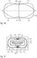
- the vestibular clamping elementhas at least two, in particular four, outward-pointing bulges that project outwards compared to a pointed oval, and that the shape of the vestibular -Clamping element is incongruent or geometrically dissimilar to the pointed oval.
- the vestibular stretcherit is preferable to shape the vestibular stretcher so that it abuts at 4 locations, i.e. upper right, lower right, lower left and upper left, to prevent slipping out.
- 4 locationsi.e. upper right, lower right, lower left and upper left.
- the lip tensioning elementhas a greater material thickness than the vestibular tensioning element.
- the filmin the non-tensioned state has a length between the lip tensioning element and the vestibular tensioning element of at most 2 cm.
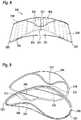
- FIG 3shows the two clamping elements (110,120) of the covering device from FIGS figures 1 and 2 .
- the vestibular tensioning element (120)is divided into four sections, two intraoral tensioning sections (123) and two anteriorly curved sections (121,122).
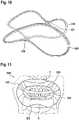
- FIG 13shows the covering device (100). figure 12 in side view.
- the two tensioning elements (110, 120) with a film 130 in betweencan be seen again.
- the vestibular clamping elementhas a section (121) running between points A and B, which forms a concave indentation (124) and thus represents a section curved in the anterior direction, which, when the covering device is inserted, extends in the sagittal anterior to the fold of the vestibulum oris.
- the vestibular tensioning element (120)is connected to the lip tensioning element (110) via a web (171).
- the preferably provided indentations 524 and 525 ( figure 16 ) of the vestibular tensioning element, corresponding to the indentations 624 and 625 of the lip tensioning element, the labial frenulum and the vestibulum orisare also relieved of pressure and protected, so that overall the wearing comfort of the covering device according to the invention is significantly improved compared to the prior art.
Landscapes
- Health & Medical Sciences (AREA)
- Oral & Maxillofacial Surgery (AREA)
- Dentistry (AREA)
- Epidemiology (AREA)
- Life Sciences & Earth Sciences (AREA)
- Animal Behavior & Ethology (AREA)
- General Health & Medical Sciences (AREA)
- Public Health (AREA)
- Veterinary Medicine (AREA)
- Dental Tools And Instruments Or Auxiliary Dental Instruments (AREA)
- Orthopedics, Nursing, And Contraception (AREA)
Abstract
Translated fromGermanDescription
Translated fromGermanDie Erfindung betrifft einen verbesserten Lippen- und Wangenexpander in Form einer Abdeckvorrichtung zum Abdecken der Lippen und Mundwinkel und zum Abhalten der Lippen, Wangen und Mundwinkel von den Zahnreihen im Mund eines Patienten.The invention relates to an improved lip and cheek expander in the form of a covering device for covering the lips and corners of the mouth and for keeping the lips, cheeks and corners of the mouth away from the rows of teeth in a patient's mouth.
Abdeckvorrichtungen zum Abhalten der Lippen, Wangen und Mundwinkel von den Zahnreihen im Mund eines Patienten sind als Wangenabhalter, Abhaltehaken oder Spreizklammern bekannt. Weiterhin beschreibt die
Derartige Abdeckvorrichtungen dienen unter anderem dazu, dem Zahnarzt den Zugang zum Mundinnenraum zu erleichtern. Die Lippen des Patienten werden durch die kombinierte Wirkung von - ringförmigen - Spannelementen und einer sich zwischen diesen erstreckenden Folie aufgespreizt und auseinandergezogen, so dass die Mundöffnung wesentlich vergrößert ist, ohne dass der Patient den Mund weiter aufsperren muss.Such covering devices serve, among other things, to make it easier for the dentist to access the interior of the mouth. The patient's lips are spread open and pulled apart by the combined effect of - ring-shaped - clamping elements and a film extending between them, so that the Mouth opening is significantly enlarged without the patient having to open his mouth further.
Solche Abdeckvorrichtungen aus dem Stand der Technik führen häufig zu schmerzhaften Druckstellen an der Schleimhaut des Alveolarknochens, insbesondere im Bereich der Eckzähne, da das intraoral liegende Spannelement durch den starken Lippendruck an den Alveolarknochen angedrückt wird. Dies gilt insbesondere für den Unterkiefer, jedoch können solche Druckstellen ebenfalls am Oberkiefer auftreten.Such covering devices from the prior art often lead to painful pressure points on the mucous membrane of the alveolar bone, particularly in the area of the canines, since the clamping element located intraorally is pressed against the alveolar bone by the strong lip pressure. This applies in particular to the lower jaw, but such pressure points can also occur on the upper jaw.
Ein weiteres Problem der Herstellung der Lippen- und Wangenexpander, also in der hiesigen Diktion, der Abdeckvorrichtungen gemäß dem Stand der Technik, ist die Mehrzahl an Größen, die für die unterschiedlichen Mundgrößen der Patienten bereitgehalten werden muss. Die "Optragates" werden eingeschweißt geliefert. Aufgrund der besonderen Anforderungen an die Folie (Dehnbarkeit, Nachgiebigkeit, Materialstärke, Reißfestigkeit) ist die Haltbarkeit auch in eingeschweißtem Zustand begrenzt, und beträgt z.B. wenige Monate.A further problem in the production of the lip and cheek expanders, ie in the local terminology, the covering devices according to the prior art, is the large number of sizes that have to be kept ready for the different mouth sizes of the patients. The "Optragates" are delivered shrink-wrapped. Due to the special requirements placed on the film (extensibility, flexibility, material strength, tear resistance), the shelf life is limited, even when shrink-wrapped, and is e.g. a few months.
Dies führt dazu, dass regelmäßig beschaffte und gelagerte Optragates nach der maximalen Lagerzeit unbrauchbar werden und entsorgt werden müssen. Auch bei der Bereitstellung von lediglich 3 oder 4 Größen führt dies zu unnötigen Kosten und überflüssigen Entsorgungsproblemen.As a result, regularly procured and stored optragates become unusable after the maximum storage time and must be disposed of. Even if only 3 or 4 sizes are provided, this leads to unnecessary costs and unnecessary disposal problems.
Demgegenüber liegt der vorliegenden Erfindung die Aufgabe zugrunde, eine verbesserte gattungsgemäße Abdeckvorrichtung gemäß dem Oberbegriff von Anspruch 1 zu schaffen, bei der Druckstellen auf der Schleimhaut des Alveolarknochens verhindert oder zumindest deutlich verringert werden und somit der Tragekomfort bei der Vorrichtung deutlich erhöht ist, so dass die Akzeptanz der Abdeckvorrichtung erhöht ist, und/oder die Lagerkosten minimiert werden.In contrast, the present invention is based on the object of creating an improved generic covering device according to the preamble of
Die vorliegende Erfindung löst das ihr zugrunde liegende technische Problem durch eine Abdeckvorrichtung nach Anspruch 1.The present invention solves the technical problem on which it is based by means of a covering device according to
Erfindungsgemäß ist eine Abdeckvorrichtung zum Abdecken der Lippen und Mundwinkel und zum Abhalten der Lippen, Wangen und Mundwinkel von den Zahnreihen im Mund eines Patienten mit einem elastischen Lippen-Spannelement zur äußeren Anlage an der Mundöffnung, mindestens einem elastischen Vestibulär-Spannelement zum Einlegen in das Vestibulum oris des Mundes des Patienten und einer die Spannelemente verbindenden Folie vorgesehen, wobei die Spannelemente entlang zweier gegenüberliegender Endbereiche der Folie angeordnet sind, so dass die eingesetzte Abdeckvorrichtung zur Mundhöhle hin offen ist. Bevorzugt setzt die Folie einem Verbiegen im Gegensatz zum Dehnen im wesentlichen keinen Widerstand entgegen. Zumindest ein intraoraler Abschnitt des Vestibulär-Spannelements ist geeignet, in elastisch verformtem Zustand in einen Bereich des Vestibulum oris des Patienten eingelegt zu werden und die Folie intraoral zu fixieren, so dass bei eingesetzter Abdeckvorrichtung die Folie zwischen dem extraoralen Lippen-Spannelement und dem im wesentlichen intraoralen Vestibulär-Spannelement in Anlage an die Lippen und Mundwinkel um diese herum verläuft und geeignet ist, im Wesentlichen gleichmäßig flächig verteilt Druckkräfte auf Lippen und Mundwinkel auszuüben, die die Lippen, Wangen und Mundwinkel von den Zähnen und dem Alveolarknochen wegdrücken und die Mundöffnung zirkulär in eine geöffnete Stellung vorspannen. Die Abdeckvorrichtung lässt auch in eingesetztem Zustand das Schließen des Mundes zu. Das Vestibulär-Spannelement weist erfindungsgemäß mindestens einen Abschnitt auf, der bei eingesetzter Abdeckvorrichtung in sagittaler Richtung anterior des Vestibulum oris, insbesondere anterior der Umschlagfalte des Vestibulum oris, oder auch anterior des Lippenbändchens verläuft. Soweit hier von "anterior des Vestibulum oris" gesprochen wird, ist natürlich der tiefste Punkt des Vestibulum oris, alos die Umschlagfalte gemeint.According to the invention is a covering device for covering the lips and corners of the mouth and for keeping the lips, cheeks and corners of the mouth from the Rows of teeth in a patient's mouth with an elastic lip tensioning element for external contact with the mouth opening, at least one elastic vestibular tensioning element for insertion into the vestibulum oris of the patient's mouth and a film connecting the tensioning elements, the tensioning elements being provided along two opposite end regions of the Foil are arranged so that the covering device used is open to the oral cavity. Preferably, the film offers essentially no resistance to bending as opposed to stretching. At least one intraoral section of the vestibular tensioning element is suitable for being placed in an area of the patient's vestibulum oris in an elastically deformed state and for fixing the foil intraorally, so that when the covering device is inserted, the foil between the extraoral lip tensioning element and the essentially intraoral vestibular tensioning element in contact with the lips and corners of the mouth runs around them and is suitable for exerting compressive forces on the lips and corners of the mouth, which are distributed essentially evenly over a large area, which press the lips, cheeks and corners of the mouth away from the teeth and the alveolar bone and the mouth opening circularly in bias an open position. The covering device also allows the mouth to be closed when it is in place. According to the invention, the vestibular tensioning element has at least one section which, when the covering device is inserted, runs in the sagittal direction anterior to the vestibulum oris, in particular anterior to the fold of the vestibulum oris, or else anterior to the labial frenulum. As far as "anterior of the vestibulum oris" is mentioned here, the deepest point of the vestibulum oris, i.e. the fold, is of course meant.
Erfindungsgemäß ist es vorgesehen, dass das Vestibulär-Spannelement mindestens einen zum Lippen-Spannelement hin, insbesondere also in Richtung anterior, gebogenen Abschnitt aufweist, der bei eingesetzter Abdeckvorrichtung insbesondere anterior der Umschlagfalte des Vestibulum oris und/oder anterior des Lippenbändchens verläuft.According to the invention, it is provided that the vestibular tensioning element has at least one section curved towards the lip tensioning element, i.e. in particular in the anterior direction, which, when the covering device is inserted, runs in particular anterior to the fold of the vestibulum oris and/or anterior to the labial frenulum.
Bevorzugt ist der mindestens einen Abschnitt des Vestibulär-Spannelements, der bei eingesetzter Vorrichtung in sagittaler Richtung anterior der Umschlagfalte des Vestibulum oris verläuft, ein in Richtung anterior gebogener, also sich näher zum Lippen-Spannelement hin erstreckender, Abschnitt.The at least one section of the vestibular tensioning element, which runs in the sagittal direction anterior to the fold of the vestibulum oris when the device is inserted, is preferably a section that is curved in the anterior direction, i.e. extending closer to the lip tensioning element.
Es zeigte sich überraschenderweise, dass eine entsprechende Formgebung des Vestibulär-Spannelements, bei der ein Abschnitt des Vestibulär-Spannelements so geformt ist, dass er in sagittaler Richtung anterior der Umschlagfalte des Vestibulum oris oder anteriro des Lippenbändchens verläuft und dabei bevorzugt in anteriorer Richtung gebogen ist, dazu führt, dass dieser Abschnitt nicht auf die Schleimhaut des Alveolarknochens drückt und somit an den entsprechenden Stellen Druckwunden und Reizungen verhindert werden und dennoch gleichzeitig die intraoral verlaufenden, demgegenüber verbleibenden Abschnitts, die Spannabschnitte des Vestibulär-Spannelements ausreichen, die Abdeckvorrichtung intraoral genügend zu fixieren. Dies gilt nicht nur für den geöffneten, sondern sogar für den geschlossenen Mund.Surprisingly, it turned out that a corresponding shaping of the vestibular tensioning element, in which a section of the vestibular tensioning element is shaped in such a way that it runs in the sagittal direction anterior to the fold of the vestibulum oris or anteriro of the frenum of the lip and is preferably bent in the anterior direction , means that this section does not press on the mucous membrane of the alveolar bone and thus pressure sores and irritations are prevented at the corresponding points and at the same time the intraorally running section, the remaining section, the clamping sections of the vestibular clamping element, are sufficient to sufficiently fix the covering device intraorally . This applies not only to the open, but even to the closed mouth.
In einer bevorzugten Ausführungsform liegt der mindestens eine Abschnitt des Vestibulär-Spannelements bei eingesetzter Abdeckvorrichtung noch gerade intraoral oder extraoral oder dazwischen, z.B. auf der Lippe des Patienten auf, im Übergangsbereich zwischen intraoral und extraoral.In a preferred embodiment, the at least one section of the vestibular tensioning element lies just intraorally or extraorally or in between, e.g. on the patient's lip, in the transition area between intraoral and extraoral when the covering device is inserted.
In einer bevorzugten Ausführungsform liegt insofern der mindestens eine Abschnitt des Vestibulär-Spannelements bei eingesetzter Vorrichtung auf der Lippe oder außerhalb der Lippe auf.In a preferred embodiment, the at least one section of the vestibular tensioning element rests on the lip or outside the lip when the device is inserted.
Wenn nicht anders erwähnt, wird unter dem "mindestens ein Abschnitt des Vestibulär-Spannelements" in der vorliegenden Beschreibung der Abschnitt des Vestibulär-Spannelements verstanden, der bei eingesetzter Abdeckvorrichtung in der Sagittalebene anterior der Umschlagfalte des Vestibulum oris verläuft und bevorzugt in Richtung anterior gebogen ist. Dieser Abschnitt des Vestibulär-Spannelements verläuft also nicht im tiefsten Bereich des Vestibulum oris, sondern verläuft durch die plastische Formgebung des Vestibulär-Spannelements versetzt zu dem Verlauf des Vestibulum oris, beispielsweise entlang der Lippe oder außerhalb der Lippe.Unless otherwise stated, “at least one section of the vestibular tensioning element” in the present description is understood to mean the section of the vestibular tensioning element which, when the covering device is inserted, runs in the sagittal plane anterior to the fold of the vestibulum oris and is preferably bent in the anterior direction . This section of the vestibular tensioning element does not run in the deepest area of the vestibulum oris, but rather runs offset to the course of the vestibulum oris due to the plastic shaping of the vestibular tensioning element, for example along the lip or outside the lip.
Es kann also vorgesehen sein, dass dieser Abschnitt, der als Einbuchtung augebildet ist, nicht im tiefsten Bereich des Vestibulum oris verläuft, aber am Innenbereich der Lippe anliegt und somit dennoch intraoral positioniert ist. Alternativ und bevorzugt kann vorgesehen sein, dass der mindestens eine Abschnitt extraoral verläuft. In dieser Ausführungsform weist das Vestibulär-Spannelement also mindestens einen intraoral verlaufenden Abschnitt und mindestens einen extraoral verlaufenden Abschnitt auf. In dieser Ausführungsform quert der Verlauf des Vestibulär-Spannelements also die Lippe, oder liegt zumindest auf dieser großflächig auf.It can therefore be provided that this section, which is designed as an indentation, does not run in the deepest area of the vestibulum oris, but rests on the inner area of the lip and is therefore still positioned intraorally. Alternatively and preferably, it can be provided that the at least one section runs extraorally. In this In this embodiment, the vestibular tensioning element has at least one section running intraorally and at least one section running extraorally. In this embodiment, the path of the vestibular tensioning element thus crosses the lip, or at least rests on it over a large area.
Insbesondere beim stark geöffneten Mund besteht die Gefahr eines Kontaktes zwischen dem Vestibulär-Spannelement und der Kieferscheimhaut.There is a risk of contact between the vestibular clamping element and the mucous membrane of the jaw, especially when the mouth is wide open.
Auch wenn z.B. in diesem Zustand die Schleimhaut der Lippe (ventrale Begrenzung des Vestibulum Oris), die Umschlagsfalte und die Schleimhaut der Kieferknochen ( dorsale Begrenzung des Vestibulum Oris) eng aufeinander liegen, verhindert die Einbuchtung als Vorwölbung des Vestibulär-Spannelements und insbesondere auch ein Steg gemäß Anspruch 16 es, dass das Vestibulär-Spannelement im anterioren Bereich die Schleimhaut des Kieferknochens berührt. Daher können dort auch niemals Druckstellen verursacht werden.Even if, for example, the mucous membrane of the lips (ventral boundary of the vestibulum oris), the folds and the mucous membrane of the jaw bones (dorsal boundary of the vestibulum oris) lie close together in this state, the indentation as a protrusion of the vestibular tension element and, in particular, a ridge prevent this according to claim 16 that the vestibular tensioning element touches the mucous membrane of the jawbone in the anterior area. Therefore, pressure points can never be caused there.
Die Vorwölbung des Vestibulär-Spannelements verformt die elastische Lippe an dieser Stelle abhaltend, also in Richtung anterior.The protrusion of the vestibular tensioning element deforms the elastic lip at this point, i.e. in an anterior direction.
Ein besonderer Vorteil ergibt sich darüber hinaus aus der Ausbildung der Einbuchtung an einer Stelle, an der die Abdeckvorrichtungen des Standes der Technik in die Umschlagfalte hineinragen und ggf. dort aufliegen: Durch die Einbuchtung wird die betreffende Stelle des Spannelements nach schräg oben bzw. zur Mundöffnung hin/anterior verlagert. Die Lippenschleimhaut ist dort sehr elastisch, so dass sie gerne nach anterior ausweicht, was das Spannelement weiter von der Alveolarfortsatz-Schleimhaut wegdrückt.A particular advantage also results from the formation of the indentation at a point where the covering devices of the prior art protrude into the fold and possibly rest there: The indentation causes the relevant point of the tensioning element to slope upwards or to open the mouth shifted towards/anteriorly. The lip mucosa is very elastic there, so that it tends to deviate anteriorly, which pushes the clamping element further away from the alveolar process mucosa.
Im Zusammenhang mit der vorliegenden Erfindung wird unter einem "anterior gebogenen Abschnitt" bevorzugt verstanden, dass der Verlauf in Richtung des Lippen-Spannelements verläuft, da dieses bei der Abdeckvorrichtung im eingesetzten Zustand gänzlich außerhalb des Mundes und somit anterior des Vestibulär-Spannelements liegt. Im Zusammenhang mit der vorliegenden Erfindung wird unter dem "Lippen-Spannelement" das Spannelement verstanden, das vollständig extraoral positioniert wird. Im Zusammenhang mit der vorliegenden Erfindung wird unter dem "Vestibulär-Spannelement" das Spannelement verstanden, das zumindest teilweise intraoral positioniert wird.In connection with the present invention, an "anteriorly curved section" is preferably understood to mean that it runs in the direction of the lip tensioning element, since this lies entirely outside the mouth and thus anterior to the vestibular tensioning element when the covering device is in place. In the context of the present invention, the "lip stretching element" is understood to mean the stretching element that is positioned completely extraorally. In connection with the present invention, the “vestibular tensioning element” is understood to mean the tensioning element that is at least partially positioned intraorally.
Bevorzugt verläuft der mindestens eine Abschnitt des Vestibulär-Spannelements bei eingesetzter Abdeckorrichtung im Bereich der Schneidezähne. Besonders bevorzugt verläuft der mindestens eine Abschnitt des Vestibulär-Spannelements bei eingesetzter Abdeckvorrichtung im Bereich der Eckzähne und der Schneidezähne.The at least one section of the vestibular tensioning element preferably runs in the region of the incisors when the covering device is inserted. The at least one section of the vestibular tensioning element particularly preferably runs in the region of the canines and the incisors when the covering device is inserted.
Es zeigt sich, dass der Druck von Spannelementen aus dem Stand der Technik im Bereich der Eck- und Schneidezähne besonders groß ist und sich hier besonders schnell und besonders starke Druckwunden an der Schleimhaut bilden. Daher ist der mindestens eine Abschnitt des Vestibulär-Spannelements, der bei eingesetzter Abdeckvorrichtung im wesentlichen in sagittaler Richtung anterior der Umschlagfalte des Vestibulum oris verläuft, bevorzugt so positioniert, dass er im Bereich der Schneidezähne, besonders bevorzugt im Bereich der Schneide- und Eckzähne verläuft und so eine Druckentlastung an den ansonsten besonders stark belasteten Druckpunkten, der an den Alveolarknochen anliegenden Schleimhaut herbeiführt.It has been shown that the pressure of clamping elements from the prior art is particularly high in the area of the canines and incisors and that pressure sores on the mucous membrane form here particularly quickly and particularly severely. Therefore, the at least one section of the vestibular tensioning element, which runs essentially in the sagittal direction anterior to the fold of the vestibulum oris when the covering device is inserted, is preferably positioned in such a way that it runs in the area of the incisors, particularly preferably in the area of the incisors and canines, and thus relieving the pressure on the pressure points, which are otherwise subject to particularly high stress, on the mucous membrane lying against the alveolar bones.
Der mindestens eine Abschnitt des Vestibulär-Spannelements und somit bevorzugt die gesamte Abdeckvorrichtung berührt bevorzugt in vorteilhafter Weise nicht die den Kieferknochen bedeckende Schleimhaut im Frontalbereich.The at least one section of the vestibular tensioning element and thus preferably the entire covering device advantageously does not touch the mucous membrane covering the jawbone in the frontal area.
Es zeigte sich in überraschender Weise, dass es trotz dieser vorteilhaften Druckentlastung zu keiner Druckverstärkung an den anderen Bereichen des Vestibulär-Spannelements kommt, insbesondere nicht an den im Bereich des Vestibulum oris liegenden Bereichen.Surprisingly, it turned out that, despite this advantageous pressure relief, there was no pressure increase in the other areas of the vestibular tensioning element, in particular not in the areas located in the area of the vestibulum oris.
Die nicht mit Knochen hinterlegten Schleimhautbereiche werden stärker für die Stütz- und Lagerfunktion der erfindungsgemäßen Abdeckvorrichtung herangezogen, was vom Patienten keineswegs als unangenehm empfunden wird. Dies gilt insbesondere auch für die Ausführungsform gemäß Anspruch 17.The areas of the mucous membrane that are not backed by bone are used more for the support and bearing function of the covering device according to the invention, which is by no means uncomfortable for the patient. This also applies in particular to the embodiment according to claim 17.
Insofern die die Akzeptanz der erfindungsgemäßen Abdeckvorrichtung deutlich erhöht, was dem Zahnarzt eine bessere Zugänglichkeit des Behandlungsbereichs und weniger Zeitstress ermöglicht.In this respect, the acceptance of the covering device according to the invention is significantly increased, which allows the dentist better access to the treatment area and less time stress.
Wenn nur ein Abschnitt des Vestibulär-Spannelements vorgesehen ist, der bei eingesetzter Abdeckvorrichtung in im wesentlichen sagittaler Richtung anterior der Umschlagfalte des Vestibulum oris verläuft, also näher am Lippen-Spannelement, so kann dieser entweder im Bereich des Unterkiefers oder im Bereich des Oberkiefers positioniert sein. Bevorzugt ist dieser eine Abschnitt im Bereich des Unterkiefers positioniert, da hier die Entstehung von Druckwunden bei der Verwendung herkömmlicher Abdeckvorrichtungen stärker ist als im Oberkieferbereich. Natürlich kann wahlweise aber auch eine Positionierung im Oberkieferbereich vorgesehen sein.If only one section of the vestibular tensioning element is provided, which runs in the substantially sagittal direction anterior to the fold of the vestibulum oris when the covering device is inserted, i.e. closer to the lip tensioning element, this can be positioned either in the area of the lower jaw or in the area of the upper jaw . This one section is preferably positioned in the area of the lower jaw, since the occurrence of pressure sores is greater here when conventional covering devices are used than in the upper jaw area. Of course, positioning in the upper jaw area can also be provided as an option.
In einer bevorzugten Ausführungsform verläuft der mindestens eine Abschnitt des Vestibulär-Spannelements bei eingesetzter Abdeckvorrichtung im Bereich der Schneidezähne des Unterkiefers.In a preferred embodiment, the at least one section of the vestibular tensioning element runs in the area of the incisors of the lower jaw when the covering device is inserted.
In einer bevorzugten Ausführungsform weist das Vestibulär-Spannelement zwei Abschnitte auf, die bei eingesetzter Abdeckvorrichtung, insbesondere in sagittaler Richtung betrachtet, anterior der Umschlagfalte des Vestibulum oris verlaufen.In a preferred embodiment, the vestibular tensioning element has two sections which, when the covering device is inserted, run anterior to the fold of the vestibulum oris, particularly viewed in the sagittal direction.
In einer bevorzugten Ausführungsform verläuft der mindestens eine Abschnitt des Vestibulär-Spannelements bei eingesetzter Abdeckvorrichtung im Bereich der Eckzähne und der Schneidezähne des Unterkiefers.In a preferred embodiment, the at least one section of the vestibular tensioning element runs in the region of the canines and the incisors of the lower jaw when the covering device is inserted.
Bevorzugt ist vorgesehen, dass die Abdeckvorrichtung ein Vestibulär-Spannelement aufweist, das zwei Abschnitte aufweist, die bei eingesetzter Abdeckvorrichtung in im wesentlichen sagittaler Richtung anterior der Umschlagfalte des Vestibulum oris verlaufen, insbesondere die in Richtung anterior gebogen sind. Dabei verläuft bevorzugt der eine Abschnitt, der in sagittaler Richtung anterior der Umschlagfalte des Vestibulum oris verläuft, im Bereich der Schneidezähne, bevorzugt der Eck- und der Schneidezähne, des Unterkiefers und der andere Abschnitt, der bei eingesetzter Abdeckvorrichtung in sagittaler Richtung anterior der Umschlagfalte des Vestibulum oris verläuft, verläuft im Bereich der Schneidezähne, insbesondere im Bereich der Eck- und Schneidezähne, im Bereich des Oberkiefers.Provision is preferably made for the covering device to have a vestibular tensioning element which has two sections which, when the covering device is inserted, run in a substantially sagittal direction anterior to the fold of the vestibulum oris, in particular which are bent in the anterior direction. One section, which runs in the sagittal direction anterior to the fold of the vestibulum oris, preferably runs in the area of the incisors, preferably the canines and incisors, of the lower jaw and the other section, which when the covering device is inserted, runs in the sagittal direction anterior to the fold of the vestibule Oris vestibule runs, runs in the area of the incisors, especially in the area of the canines and incisors, in the area of the upper jaw.
In einer bevorzugten Ausführungsform verläuft bei eingesetzter Abdeckvorrichtung der erste Abschnitt im Bereich der Eckzähne und der Schneidezähne des Unterkiefers und der zweite Abschnitt verläuft im Bereich der Eckzähne und der Schneidezähne des Oberkiefers.In a preferred embodiment, when the covering device is inserted, the first section runs in the region of the canines and incisors of the lower jaw and the second section runs in the region of the canines and incisors of the upper jaw.
In einer weiteren bevorzugten Ausführungsform ist das Vestibulär-Spannelement als Spannrahmen, insbesondere als Spannring, ausgebildet ist, der plastisch dreidimensional geformt ist.In a further preferred embodiment, the vestibular tensioning element is designed as a tensioning frame, in particular as a tensioning ring, which is plastically shaped in three dimensions.
Durch die plastische dreidimensionale Formung kann der erfindungsgemäße Verlauf des Vestibulär-Spannelements, wie wahlweise auch des Lippen-Spannelements, erreicht werden, wobei durch das elastische Material der Spannelemente diese noch so flexibel sind, dass die Abdeckvorrichtung im und am Mund verwendet werden kann.The plastic three-dimensional shape allows the vestibular tensioning element to run according to the invention, as well as optionally the lip tensioning element, with the elastic material of the tensioning elements still being so flexible that the covering device can be used in and on the mouth.
In einer bevorzugten Ausführungsform ist das Vestibulär-Spannelement bei eingesetzter Abdeckvorrichtung im Bereich des mindestens einen Abschnitts 0 mm bis 30 mm vom Lippen-Spannelement entfernt.In a preferred embodiment, when the covering device is inserted, the vestibular tensioning element is 0 mm to 30 mm away from the lip tensioning element in the area of the at least one section.
In einer bevorzugten Ausführungsform ist das Vestibulär-Spannelement bei eingesetzter Abdeckvorrichtung 0 mm vom Lippen-Spannelement entfernt, die Spannelemente liegen also an ein oder zwei Punkten aneinander an oder sind an diesen ein oder zwei Punkten sogar miteinander verbunden.In a preferred embodiment, the vestibular tensioning element is 0 mm away from the lip tensioning element when the covering device is inserted, ie the tensioning elements abut one another at one or two points or are even connected to one another at these one or two points.
In einer bevorzugten Ausführungsform ist das Vestibulär-Spannelement bei eingesetzter Abdeckvorrichtung im Bereich des mindestens einen Abschnitts mehr als 0 mm bis 30 mm vom Lippen-Spannelement entfernt. In einer bevorzugten Ausführungsform ist das Vestibulär-Spannelement bei eingesetzter Abdeckvorrichtung im Bereich des mindestens einen Abschnitts 0,1 mm bis 30 mm vom Lippen-Spannelement entfernt. In einer bevorzugten Ausführungsform ist das Vestibulär-Spannelement bei eingesetzter Abdeckvorrichtung im Bereich des mindestens einen Abschnitts höchstens 25 mm vom Lippen-Spannelement entfernt. In einer bevorzugten Ausführungsform ist das Vestibulär-Spannelement bei eingesetzter Abdeckvorrichtung im Bereich des mindestens einen Abschnitts höchstens 20 mm vom Lippen-Spannelement entfernt. In einer bevorzugten Ausführungsform ist das Vestibulär-Spannelement bei eingesetzter Abdeckvorrichtung im Bereich des mindestens einen Abschnitts höchstens 15 mm vom Lippen-Spannelement entfernt.In a preferred embodiment, when the covering device is inserted, the vestibular tensioning element is more than 0 mm to 30 mm away from the lip tensioning element in the area of the at least one section. In a preferred embodiment, when the covering device is inserted, the vestibular tensioning element is 0.1 mm to 30 mm away from the lip tensioning element in the area of the at least one section. In a preferred embodiment, when the covering device is inserted, the vestibular tensioning element is at most 25 mm away from the lip tensioning element in the area of the at least one section. In a preferred In the embodiment, when the covering device is inserted, the vestibular tensioning element is at most 20 mm away from the lip tensioning element in the area of the at least one section. In a preferred embodiment, when the covering device is inserted, the vestibular tensioning element is at most 15 mm away from the lip tensioning element in the area of the at least one section.
In einer bevorzugten Ausführungsform ist das Vestibulär-Spannelement bei eingesetzter Abdeckvorrichtung im Bereich des mindestens einen Abschnitts bis 30 mm vom Lippen-Spannelement entfernt.In a preferred embodiment, when the covering device is inserted, the vestibular tensioning element is up to 30 mm away from the lip tensioning element in the area of at least one section.
In einer bevorzugten Ausführungsform weist das Lippen-Spannelement mindestens einen Abschnitt auf, der bei eingesetzter Abdeckvorrichtung in sagittaler Richtung in Richtung des mindestens einen Abschnitts des Vestibulär-Spannelements gekrümmt ist.In a preferred embodiment, the lip tensioning element has at least one section which, when the covering device is inserted, is curved in the sagittal direction in the direction of the at least one section of the vestibular tensioning element.
Ein solcher Abschnitt des Lippen-Spannelements liegt bei eingesetzter Abdeckvorrichtung bevorzugt oben oder unten, also im Bereich der Nase oder des Kinns. Dies hat den Vorteil, dass die Abdeckvorrichtung die Nase oder das Kinn nicht abdeckt. Bevorzugt liegt also dieser Abschnitt des Lippen-Spannelements gegenüber dem mindestens einen Abschnitt des Vestibulär-Spannelements.When the covering device is inserted, such a section of the lip tensioning element is preferably at the top or bottom, ie in the area of the nose or chin. This has the advantage that the covering device does not cover the nose or the chin. This section of the lip tensioning element is therefore preferably located opposite the at least one section of the vestibular tensioning element.
In einer besonders bevorzugten Ausführungsform weist das Lippen-Spannelement zwei Abschnitte auf, die bei eingesetzter Abdeckvorrichtung in im wesentlichen sagittaler Richtung in Richtung des mindestens einen Abschnitts des Vestibulär-Spannelements gekrümmt sind, die also bevorzugt konkave Einbuchtungen sind.In a particularly preferred embodiment, the lip tensioning element has two sections which, when the covering device is inserted, are curved in a substantially sagittal direction in the direction of at least one section of the vestibular tensioning element, which are therefore preferably concave indentations.
Die beiden Abschnitte des Lippen-Spannelements liegen bei eingesetzter Abdeckvorrichtung bevorzugt oben und unten, also im Bereich der Nase oder des Kinns. Dies hat den Vorteil, dass die Abdeckvorrichtung die Nase und das Kinn nicht abdeckt. Bevorzugt liegen also diese Abschnitte des Lippen-Spannelements gegenüber den zwei Abschnitten des Vestibulär-Spannelements.When the covering device is inserted, the two sections of the lip tensioning element are preferably at the top and bottom, ie in the area of the nose or chin. This has the advantage that the covering device does not cover the nose and chin. These sections of the lip tensioning element are therefore preferably located opposite the two sections of the vestibular tensioning element.
Somit nähern sich bevorzugt die Abschnitte des Vestibulär-Spannelements und des Lippen-Spannelements gegenseitig an. In einer bevorzugten Ausführungsform nähern sich diese Abschnitte auf einen Abstand von 0 mm bis 30 mm an, insbesondere von 0,5 mm bis 25 mm. In einer bevorzugten Ausführungsform können sich die Abschnitte auch treffen, haben also einen Abstand von 0 mm und können dabei besonders bevorzugt auch verbunden, insbesondere fest verbunden sein, was die Stabilität der Abdeckvorrichtung erhöht. Durch die Elastizität der Spannelemente bleibt die Abdeckvorrichtung dennoch für den Gebrauch flexibel genug. Trotz einer solcher Verbindung der Spannelemente bleibt die Abdeckvorrichtung zudem flexibel genug, um platzsparend verpackt zu werden.Thus, the sections of the vestibular tensioning element and the lip tensioning element preferably approach one another. In a preferred embodiment, approach these sections are at a distance of 0 mm to 30 mm, in particular from 0.5 mm to 25 mm. In a preferred embodiment, the sections can also meet, ie have a distance of 0 mm and can particularly preferably also be connected, in particular firmly connected, which increases the stability of the covering device. Due to the elasticity of the tensioning elements, the covering device nevertheless remains flexible enough for use. Despite such a connection of the clamping elements, the covering device also remains flexible enough to be packed in a space-saving manner.
In einer bevorzugten Ausführungsform bildet der mindestens eine Abschnitt des Vestibulär-Spannelements eine konkave Einbuchtung aus, wobei die konkave Einbuchtung zumindest teilweise von einer Folie überspannt wird.In a preferred embodiment, the at least one section of the vestibular tensioning element forms a concave indentation, with the concave indentation being at least partially covered by a film.
In einer bevorzugten Ausführungsform bildet der mindestens eine Abschnitt des Lippen-Spannelements eine konkave Einbuchtung aus, wobei die konkave Einbuchtung zumindest teilweise von einer Folie oder der Folie überspannt wird.In a preferred embodiment, the at least one section of the lip tensioning element forms a concave indentation, with the concave indentation being at least partially spanned by a foil or the foil.
Wenn die konkaven Ausbuchtungen der Spannelemente zumindest teilweise mit einer Folie überspannt sind, hat dies den Vorteil, dass trotz der dreidimensional geformten Spannelemente die Gesamt-Abdeckvorrichtung die Grundform der bisherigen Produkte beibehält und somit der Verbraucher nicht an eine neue Form gewöhnt werden muss.If the concave bulges of the clamping elements are at least partially covered with a film, this has the advantage that, despite the three-dimensionally shaped clamping elements, the overall covering device retains the basic shape of the previous products and the consumer therefore does not have to get used to a new shape.
In einer bevorzugten Ausführungsform hat die Abdeckvorrichtung die Form einer Röhre, bei der mindestens ein Ende der Röhre zwei konkave Einbuchtungen aufweist.In a preferred embodiment, the covering device is in the form of a tube, in which at least one end of the tube has two concave indentations.
In einer weiteren bevorzugten Ausführungsform hat die Abdeckvorrichtung die Form einer Röhre mit zwei Enden, bei der mindestens das zweite Ende der Röhre zwei konkave Einbuchtungen aufweist.In a further preferred embodiment, the covering device is in the form of a tube with two ends, in which at least the second end of the tube has two concave indentations.
Wenn die Spannelemente als Spannrahmen, insbesondere als Spannring, ausgestaltet sind, dann hat das Vestibulär-Spannelement bevorzugt einen größeren Durchmesser als das Lippen-Spannelement.If the tensioning elements are designed as a tensioning frame, in particular as a tensioning ring, then the vestibular tensioning element preferably has a larger diameter than the lip tensioning element.
Bevorzugt sind unter "Folie" ein im weitesten Sinne flächige Gebilde zu verstehen, die einem Verbiegen im Gegensatz zum Dehnen im wesentlichen keinen Widerstand entgegensetzen. Solche Gebilde können auch als folienartige Mittel bezeichnet werden. Folienartige Mittel können aus elastisch dehnbarem, aber im Prinzip auch aus undehnbarem Material hergestellt sein."Foil" is preferably to be understood as meaning a flat structure in the broadest sense, which offers essentially no resistance to bending, in contrast to stretching. Such structures can also be referred to as film-like means. Foil-like means can be made of elastically stretchable, but in principle also of non-stretchable material.
Im Gegensatz zum Stand der Technik wird von erfindungsgemäßen Lippen- und Wangenexpandern auf die Lippen und Wangen, die von den Zahnreihen abzuhalten sind, über die folienartigen Mittel eine Druckkraft großflächig verteilt ausgeübt. Die folienartigen Mittel sind bevorzugt an einem Ende mit dem zumindest teilweise innerhalb der Mundhöhle befindlichen Vestibulär-Spannelement und am anderen Ende mit dem auf den Lippen bzw. Wangen außen anliegenden äußeren Lippen-Spannelement verbunden.In contrast to the prior art, lip and cheek expanders according to the invention exert a compressive force over a large area on the lips and cheeks that are to be kept away from the rows of teeth. The foil-like means are preferably connected at one end to the vestibular tensioning element located at least partially within the oral cavity and at the other end to the outer lip tensioning element lying on the outside of the lips or cheeks.
Es können auch zusätzliche weitere folienartige Mittel vorgesehen sein, die beispielsweise die Einbuchtungen im Lippen-und/oder Vestibulär-Spannelement zumindest teilweise abdecken.Additional film-like means can also be provided which, for example, at least partially cover the indentations in the lip and/or vestibular tension element.
Die folienartigen Abdeckmittel sind vorteilhaft dünn und elastisch ausgebildet. Im Zusammenspiel mit den zwei Spannelementen können sehr einfache, extrem flexible und breit anwendbare Lippen- und Wangenexpander, also Abdeckvorrichtungen, geschaffen werden. Beim Anlegen des Expanders werden von den folienartigen Mitteln Druckkräfte großflächig verteilt und zirkulär um die Mundöffnung aufgebaut. Dadurch kann für den Patienten auf bequeme Art die Mundöffnung zirkulär weit geöffnet gehalten und gleichzeitig die Lippen und Wangen sanft von den Zahnreihen abgehalten werden.The foil-like covering means are advantageously thin and elastic. In combination with the two clamping elements, very simple, extremely flexible and widely applicable lip and cheek expanders, i.e. covering devices, can be created. When the expander is put on, pressure forces are distributed over a large area by the film-like means and built up circularly around the mouth opening. As a result, the mouth opening can be kept wide open in a circular manner for the patient in a comfortable way and at the same time the lips and cheeks can be gently kept away from the rows of teeth.
Darüber hinaus kann bei der erfindungsgemäß bevorzugten dreidimensionalen Formgebung auch des Lippen-Spannelements in vorteilhafter Weise verhindert werden, dass die Folie störend die Nase abdeckt.In addition, with the three-dimensional shape preferred according to the invention, the lip tensioning element can also be prevented in an advantageous manner from the foil covering the nose in a disruptive manner.
Dem Fachmann sind geeignete Materialien für die Spannelemente und die Folie bekannt, beispielsweise aus der
Materialstärke und Materialform, also der Querschnitt der Spannelemente, insbesondere des Vestibulär-Spannelements, können vom Fachmann frei gewählt werden. Es kann auch vorgesehen sein, dass die Materialstärke und die Materialform der Spannelemente, insbesondere des Vestibulär-Spannelements, über deren Verlauf variiert. Durch eine Variation kann der Fachmann die Biegsamkeit eines Spannelements in bestimmten Bereichen beeinflussen, also verstärken oder schwächen.The thickness and shape of the material, ie the cross-section of the tensioning elements, in particular of the vestibular tensioning element, can be freely selected by a person skilled in the art. It can also be provided that the material thickness and the material form of the tensioning elements, in particular of the vestibular tensioning element, vary over their course. By means of a variation, the person skilled in the art can influence the flexibility of a tensioning element in certain areas, ie strengthen or weaken it.
In einer alternativen Ausführungsform kann das Vestibulär-Spannelement zum intraoralen Absaugen verwendet werden. Dabei kann beispielsweise das Vestibulär-Spannelement als hohle Röhre ausgebildet sein, die in den Bereichen, die intraoral positioniert sind, Öffnungen aufweist, durch die die Mundflüssigkeit abgesaugt werden kann. Die Flüssigkeit kann dann beispielsweise über einen Steg, der bevorzugt das Vestibulär-Spannelement mit dem Lippen-Spannelement verbindet, abgeleitet werden, wenn dieser Steg ebenfalls röhrchenförmig ausgebildet ist. Durch diese Ausführungsform kann in vorteilhafter Weise die Notwendigkeit der Verwendung eines Saugers reduziert werden, beziehungsweise auf die Verwendung eines Saugers verzichtet werden.In an alternative embodiment, the vestibular tensioning element can be used for intraoral suction. In this case, for example, the vestibular tensioning element can be designed as a hollow tube that has openings in the areas that are positioned intraorally, through which the oral fluid can be sucked out. The liquid can then be drained off, for example, via a web which preferably connects the vestibular tensioning element to the lip tensioning element, if this web is also designed in the form of a small tube. This embodiment can advantageously reduce the need to use a suction cup, or the use of a suction cup can be dispensed with.
In einer bevorzugten Ausführungsform ist das Vestibulär-Spannelement mit dem Lippen-Spannelement über mindestens einen Steg, insbesondere über einen Steg oder über zwei Stege, verbunden. Bevorzugt verläuft der mindestens eine Steg in mindestens einer konkaven Einbuchtung des Vestibulär-Spannelements.In a preferred embodiment, the vestibular tensioning element is connected to the lip tensioning element via at least one web, in particular via one web or via two webs. The at least one web preferably runs in at least one concave indentation of the vestibular tensioning element.
Bevorzugt ist dabei eine Ausführungsform, bei der die beiden konkaven Ausbuchtungen des Vestibulär-Spannelements über einen Steg mit dem Lippen-Spannelement verbunden sind. In der bevorzugten Ausführungsform sind zwei Stege oder sogar mehrere Stege vorgesehen. Es ist aber auch möglich, lediglich einen Steg zu verwenden.An embodiment is preferred in which the two concave bulges of the vestibular tensioning element are connected to the lip tensioning element via a web. In the preferred embodiment, two ridges or even more ridges are provided. However, it is also possible to use only one bridge.
Derartige Stege können entweder aus dem Folienmaterial bestehen, oder aus einem hierfür geeigneten andere Material.Such webs can either consist of the film material or of another material suitable for this purpose.
Als Stege können auch Rippen realisiert werden. Diese können kurzerhand durch eine rippenförmige Verdickung des Materials der Folie ausgebildet werden. Diese können auch gekrümmt verlaufen, um den Zugwiderstand und die Festigkeit der Folie in besonderer Weise an den Stellen, an denen die Rippen ausgebildet sind, zu erhöhen.Ribs can also be implemented as webs. These can be formed without further ado by thickening the material of the film in the form of ribs. These can also be curved in order to increase the tensile strength and the strength of the film in a special way at the points where the ribs are formed.
Die Stege sind bevorzugt biegbar, aber im Vergleich mit der Folie weniger dehnbar. Die Stege können in vorteilhafter Weise ein Rutschen des inneren Rings auf das Zahnfleisch und den damit verbundenen Druckschmerz weiter verhindern. Das Lippen-Spannelement ist bevorzugt stabiler und zieht in vorteilhafter Weise das Lippen-Spannelement über die nicht dehnbaren Stege vom Zahnfleisch weg. Die Stege können in vorteilhafter Weise eine Dehnung der Folie im mittleren Lippenbereich verhindern, so dass eine Dehnung primär in den Seitenbereichen stattfindet. Die Breite der Stege kann der Fachmann frei wählen. Alternativ zu den Stegen können auch Rillen oder Bänder vorgesehen sein, und die nicht dehn- oder stauchbaren Stege können einen Abstand der beiden Ringe im Frontbereich von beispielsweise 18 mm bis 20 mm definieren.The webs are preferably flexible but less stretchable compared to the film. The webs can advantageously further prevent slipping of the inner ring onto the gums and the pressure pain associated therewith. The lip stretching element is preferably more stable and advantageously pulls the lip stretching element away from the gums via the inextensible webs. The webs can advantageously prevent stretching of the film in the central lip area, so that stretching primarily takes place in the side areas. The specialist can choose the width of the webs freely. As an alternative to the webs, grooves or bands can also be provided, and the webs that cannot be stretched or compressed can define a distance between the two rings in the front area of, for example, 18 mm to 20 mm.
Gemäß einem weiteren Aspekt der Erfindung, der in Anspruch 17 seinen Ausdruck findet, ist es vorgesehen, dass das Vestibulär-Spannelement mindestens zwei, insbesondere vier, nach außen weisende Ausbuchtungen aufweist, die gegenüber einem Spitzoval nach außen vorspringen, und dass die Form des Vestibulär-Spannelements gegenüber dem Spitzoval inkongruent oder geometrisch unähnlich ist. Diese Lösung erlaubt es überraschend, mit wesentlich weniger Größen der Abdeckvorrichtung auszukommen, und damit die Lagerhaltung zu vereinfachen und die zugehörigen Kosten zu minimieren.According to a further aspect of the invention, which is expressed in claim 17, it is provided that the vestibular clamping element has at least two, in particular four, outward-pointing bulges that project outwards compared to a pointed oval, and that the shape of the vestibular -Clamping element is incongruent or geometrically dissimilar to the pointed oval. Surprisingly, this solution makes it possible to manage with significantly smaller sizes of the covering device, and thus to simplify storage and to minimize the associated costs.
Der Mund eines Patienten in halbgeöffnetem Zustand bildet ein Spitzoval, also ein spitzes Oval oder ein Oval, das an seinen Schmalseiten zugespitzt ist. Mit den vorstehend genannten Merkmalen ist das Vestibulär-Spannelement in einer Weise formverschieden vom Mund des Patienten, dass mit einer Abdeckvorrichtung auch sehr unterschiedliche Mundgrößen abgedeckt werden können.The mouth of a patient in a half-open state forms a pointed oval, i.e. a pointed oval or an oval that is pointed at its narrow sides. With the features mentioned above, the vestibular tensioning element is shaped differently from the patient's mouth in such a way that very different mouth sizes can also be covered with one covering device.
Damit sind die Lagerkosten nicht nur wesentlich reduziert, sondern auch die Herstellkosten, denn es lediglich erforderlich, ein Spritzgusswerkzeug herzustellen, und nicht 3 oder 4.This not only significantly reduces the storage costs, but also the manufacturing costs, because it is only necessary to produce one injection mold and not 3 or 4.
Erfindungsgemäß sind Ausbuchtungen des Vestibulär-Spannelements gegenüber der Kreisform radial nach außen vorgesehen. Die Ausbuchtungen haben je selbst eine runde Außenform mit einem Radius, der kleiner als der Radius eines Standard-Vestibulärringes ist, beispielsweise zwischen 0,1 cm und 5 cm, bevorzugt 2 bis 3 cm. Dieser Radius kann auch in einer beliebigen anderen Weise gewählt werden, z.B. zwischen 0,3 cm und 4 cm, aber auch zwischen 0,8 cm und 2,5 cm.According to the invention, bulges of the vestibular tensioning element are provided radially outwards compared to the circular shape. The bulges each have a round outer shape with a radius that is smaller than the radius of a standard vestibular ring, for example between 0.1 cm and 5 cm, preferably 2 to 3 cm. This radius can also be chosen in any other way, for example between 0.3 cm and 4 cm, but also between 0.8 cm and 2.5 cm.
Das in dieser erfindungsgemäßen Ausprägung vorgesehene Vestibulär-Spannelement ist insofern der Rechteckform angenähert und erscheint bevorzugt wie ein Rechteck mit abgerundeten Ecken.In this respect, the vestibular tensioning element provided in this embodiment according to the invention approximates the shape of a rectangle and preferably appears like a rectangle with rounded corners.
Die gegenüber dem Mundoval gegenläufige Linienführung stellt insofern eine erfindungsgemäße Besonderheit dar. Die divergierenden Bereiche, besonders die Ausbuchtungsecken, dienen der Abstützung des Vestibulär-Spannelements innen am Mund des Patienten. Die kritischen Bereiche in der Sagittalebene, also der Bereich der Lippenbändchen, und in der Horizontalebene werden bewusst vermieden, dort wird bewusst kein Abstützdruck ausgeübt.The line running in the opposite direction to the mouth oval represents a special feature according to the invention. The diverging areas, especially the bulge corners, serve to support the vestibular tensioning element on the inside of the patient's mouth. The critical areas in the sagittal plane, i.e. the area of the labial frenulum, and in the horizontal plane are deliberately avoided, and no supporting pressure is deliberately exerted there.
Die erfindungsgemäßen "Stützbereiche" des Vestibulär-Spannelements an den Ausbuchtungsecken, also links/oben, links/unten, rechts/oben und rechts/unten liegen innen im Mund an und geben auch dann Halt, wenn die Größe des Spannelements für den Mund des Patienten recht groß oder recht klein ist.The "support areas" of the vestibular clamping element according to the invention at the bulge corners, i.e. left/top, left/bottom, right/top and right/bottom, lie inside the mouth and also provide support if the size of the clamping element is too large for the patient's mouth is quite large or quite small.
Wenn das Spannelement für den Patienten recht groß ist, wandert die Ausbuchtungsecke innen an der Wange entlang Richtung distal. Wenn das Spannelement recht klein ist, stützen die Ausbuchtungsecken immer noch ab, aufgrund der Formverschiedenheit oder Inkongruenz zum Oval oder Spitzoval einer Mundöffnung.If the stent is quite large for the patient, the bulge corner will migrate distally along the inside of the cheek. If the stent is quite small, the bulge corners will still support due to the shape difference or incongruity with the oval or pointed oval of a mouth opening.
So können mehrere Optragate-Größen abgedeckt werden.This allows multiple Optragate sizes to be covered.
Es ist bevorzugt, das Vestibulär-Spannelement so zu formen, dass es an 4 Stellen, also oben rechts, unten rechts, unten links und oben links anliegt, um das Herausrutschen zu verhindern. Es ist aber auch möglich, die Anzahl dieser Stellen zu variieren, und z.B. 2, 3, 5 oder 6 Stellen vorzusehen.It is preferable to shape the vestibular stretcher so that it abuts at 4 locations, i.e. upper right, lower right, lower left and upper left, to prevent slipping out. However, it is also possible to vary the number of these positions, and to provide, for example, 2, 3, 5 or 6 positions.
Es käme auch ein Anliegen außerhalb der hier beschriebenen Bereiche oder Stellen in Betracht.A concern outside of the areas or positions described here could also be considered.
Das zugehörige Lippen-Spannelement kann auch in gleicher Weise geformt sein, also zum Vestibulär-Spannelement kongruent, oder auch oval oder kreisförmigThe associated lip tensioning element can also be shaped in the same way, i.e. congruently to the vestibular tensioning element, or also oval or circular
Eine besonderer Vorteil dieser Ausführungsform mit den Ausbuchtungsecken ist es auch, dass die Aufspreizwirkung besonders seitlich nach außen wirkt. Die für das Scannen wichtigen vestibulären Bereiche an den Molaren werden dadurch besonders gut zugänglich.It is also a particular advantage of this embodiment with the bulge corners that the spreading effect acts particularly laterally outwards. This makes the vestibular areas on the molars, which are important for scanning, particularly easy to access.
Ein Scankopf kann dann besonders gut seitlich eingeführt werden, um den Vestibulärbereich der Molaren zu scannen, da dort großzügig Räume freigelassen werden.A scan head can then be inserted particularly well from the side in order to scan the vestibular area of the molars, since generous spaces are left free there.
Die Ausbuchtungen sollten bevorzugt rund sein, der optimale Radius oder ggf. Kurvenverlauf kann in weiten Bereichen an die Erfordernisse angepasst werden.The bulges should preferably be round, the optimum radius or, if necessary, the course of the curve can be adapted to the requirements over a wide range.
Diese Lösung hat einen inneren Wirkungszusammenhang mit der Lösung mit dem anterior gebogenen Abschnitt gemäß Anspruch 1: Durch den gebogenen Abschnitt geht an der dortigen Einbuchtung Retention verloren. Erfindungsgemäß vorteilhaft wird dies durch die Ausbuchtungen an anderer Stelle, den "Flügeln" oder "Ohren", also den Ausbuchtungsecken, kompensiert.This solution has an internal functional connection with the solution with the anteriorly curved section according to claim 1: The curved section causes retention at the indentation there to be lost. According to the invention, this is advantageously compensated for by the bulges at another point, the "wings" or "ears", ie the bulge corners.
Gemäß einer vorteilhaften Ausgestaltung dieser Lösung ist das Vestibulär-Spannelement um eine vertikale Achse, die posterior dieses Spannelements liegt, leicht gekrümmt. Bei kleineren Mundöffnungen verlagern sich Ausbuchtungsecken in den nachgiebigen Wangenbereich nach distal. Die Ausbuchtungsecken finden aber bei größeren Mundöffnungen dennoch Halt.According to an advantageous embodiment of this solution, the vestibular tightening element is slightly curved about a vertical axis located posterior to this tightening element. With smaller mouth openings, bulge corners shift to the yielding cheek area distally. However, the bulge corners still find support with larger mouth openings.
Die vorliegende Erfindung betrifft auch eine Abdeckvorrichtung zum Abdecken der Lippen und Mundwinkel und zum Abhalten der Lippen, Wangen und Mundwinkel von den Zahnreihen im Mund eines Patienten mit einem elastischen Lippen-Spannelement zur äußeren Anlage an der Mundöffnung, mindestens einem elastischen Vestibulär-Spannelement zum Einlegen in das Vestibulum oris des Mundes des Patienten und einer die Spannelemente verbindenden Folie, wobei die Spannelemente entlang zweier gegenüberliegender Endbereiche der Folie angeordnet sind, so dass die eingesetzte Abdeckvorrichtung zur Mundhöhle hin offen ist, wobei:
- die Folie einem Verbiegen im Gegensatz zum Dehnen im Wesentlichen keinen Widerstand entgegensetzt, und
- zumindest ein intraoralen Abschnitt des Vestibulär-Spannelements geeignet ist, in elastisch verformtem Zustand in einen Bereich des Vestibulum oris des Patienten eingelegt zu werden und die Folie intraoral zu fixieren,
- so dass bei eingesetzter Abdeckvorrichtung die Folie zwischen dem extraoralen Lippen-Spannelement und dem Vestibulär-Spannelement in Anlage an die Lippen und Mundwinkel um diese herum verläuft und geeignet ist, im Wesentlichen gleichmäßig flächig verteilt Druckkräfte auf Lippen und Mundwinkel auszuüben, die die Lippen, Wangen und Mundwinkel von den Zähnen und dem Alveolarknochen wegdrücken und die Mundöffnung zirkulär in eine geöffnete Stellung vorspannen, wobei die Abdeckvorrichtung das Schließen des Mundes zulässt, und
- wobei das Vestibulär-Spannelement mit dem Lippen-Spannelement über mindestens einen Steg, insbesondere über einen Steg oder über zwei Stege, verbunden ist.
- the film offers substantially no resistance to bending as opposed to stretching, and
- at least one intraoral section of the vestibular tensioning element is suitable for being placed in an area of the vestibulum oris of the patient in an elastically deformed state and for fixing the film intraorally,
- so that when the covering device is used, the film runs between the extraoral lip tensioning element and the vestibular tensioning element in contact with the lips and corners of the mouth around them and is suitable for exerting compressive forces on the lips and corners of the mouth, which are distributed essentially evenly over the entire area, the lips, cheeks and press corners of the mouth away from the teeth and alveolar bone and circularly bias the mouth opening to an open position with the covering device allowing the mouth to be closed, and
- wherein the vestibular tensioning element is connected to the lip tensioning element via at least one web, in particular via one web or via two webs.
Gemäß einer ersten bevorzugten Ausführungsform der Erfindung ist es vorgesehen, dass das Lippen-Spannelement und/oder die Folie eine Kraft auf das Vestibulär-Spannelement ausüben, durch die der Anpressdruck des Vestibulär-Spannelements auf die den Alveolarknochen bedeckende Mukosa verringert wird.According to a first preferred embodiment of the invention, it is provided that the lip tensioning element and/or the film exert a force on the vestibular tensioning element, which reduces the contact pressure of the vestibular tensioning element on the mucosa covering the alveolar bone.
Gemäß einer zweiten bevorzugten Ausführungsform der Erfindung ist es vorgesehen, dass das bei eingesetzter Abdeckvorrichtung das Vestibulär-Spannelement zumindest teilweise flächig an der den Alveolarknochen bedeckenden Mukosa anliegt.According to a second preferred embodiment of the invention, it is provided that when the covering device is inserted, the vestibular tensioning element bears at least partially flat against the mucosa covering the alveolar bone.
Gemäß einer dritten bevorzugten Ausführungsform der Erfindung ist es vorgesehen, dass das Lippen-Spannelement eine größere Materialstärke aufweist als das Vestibulär-Spannelement.According to a third preferred embodiment of the invention, it is provided that the lip tensioning element has a greater material thickness than the vestibular tensioning element.
Gemäß einer vierten bevorzugten Ausführungsform der Erfindung ist es vorgesehen, die Folie mindestens eine zwischen dem Lippen-Spannelement und dem Vestibulär-Spannelement verlaufenden rippenförmige Erhöhung aufweist, insbesondere eine Riffelung, aufweist.According to a fourth preferred embodiment of the invention, it is provided that the film has at least one rib-shaped elevation running between the lip tensioning element and the vestibular tensioning element, in particular a corrugation.
Gemäß einer fünften bevorzugten Ausführungsform der Erfindung ist es vorgesehen, dass die Folie im Bereich des Lippen-Spannelements eine größere Materialdicke aufweist als im Bereich des Vestibulär-Spannelements.According to a fifth preferred embodiment of the invention, it is provided that the film has a greater material thickness in the area of the lip tensioning element than in the area of the vestibular tensioning element.
Gemäß einer sechsten bevorzugten Ausführungsform der Erfindung ist es vorgesehen, dass das Lippen-Spannelement weniger elastisch ist als das Vestibulär-Spannelement.According to a sixth preferred embodiment of the invention, it is provided that the lip tensioning element is less elastic than the vestibular tensioning element.
Gemäß einer siebten bevorzugten Ausführungsform der Erfindung ist es vorgesehen, dass in nicht gespanntem Zustand die Folie eine Länge zwischen dem Lippen-Spannelement und Vestibulär-Spannelement von höchstens 2 cm hat.According to a seventh preferred embodiment of the invention, it is provided that in the non-tensioned state the film has a length between the lip tensioning element and the vestibular tensioning element of at most 2 cm.
Gemäß einer achten bevorzugten Ausführungsform der Erfindung ist es vorgesehen, dass die Folie an dem Vestibulär-Spannelement an dem Bereich oder der Fläche des Vestibulär-Spannelements befestigt ist, die in Richtung des Lippen-Spannelements zeigt oder an der Fläche des Vestibulär-Spannelements befestigt ist, die den größten Durchmesser aufweist, oder dazwischen.According to an eighth preferred embodiment of the invention, it is provided that the foil is attached to the vestibular tensioning element on the area or surface of the vestibular tensioning element which points in the direction of the lip tensioning element or is attached to the surface of the vestibular tensioning element , which has the largest diameter, or in between.
Gemäß einer neunten bevorzugten Ausführungsform der Erfindung ist es vorgesehen, dass das Vestibulär-Spannelement nach der Herstellung keinen Anguss an der Fläche aufweist, die nach dem Einlegen des Vestibulär-Spannelements in das Vestibulum oris des Mundes des Patienten an der den Alveolarknochen bedeckenden Mukosa anliegt.According to a ninth preferred embodiment of the invention, it is provided that the vestibular tensioning element does not have a sprue on the surface after production which, after the vestibular clamping element has been inserted into the vestibulum oris of the patient's mouth, rests against the mucosa covering the alveolar bone.
Bevorzugte Ausführungsformen ergeben sich auch aus den Unteransprüchen.Preferred embodiments also emerge from the dependent claims.
Die vorliegende Erfindung wird anhand der folgenden Figuren und Beispiele näher erläutert, ohne dass diese einschränkend zu verstehen wären.
Figur 1Figur 2 zeigt die Seitenansicht der Abdeckvorrichtung ausFigur 1 ;Figur 3 zeigt die beiden Spannelemente der Abdeckvorrichtung ausFigur 1 ;Figur 4 zeigt eine alternative erfindungsgemäße Abdeckvorrichtung;Figur 5 zeigt die Seitenansicht der Abdeckvorrichtung ausFigur 4 ;Figur 6 zeigt die beiden Spannelemente der Abdeckvorrichtung ausFigur 4 ;Figur 7 zeigt eine weitere alternative erfindungsgemäße Abdeckvorrichtung;Figur 8 zeigt die Seitenansicht der Abdeckvorrichtung ausFigur 7 ;Figur 9 zeigt die beiden Spannelemente der Abdeckvorrichtung ausFigur 7 ;Figur 10 zeigt die beiden Spannelemente in einer weiteren Ausführungsform;Figur 11 zeigt einen Vergleich der erfindungsgemäßen Abdeckvorrichtung mit einer Abdeckvorrichtung aus dem Stand der Technik während der Verwendung;Figur 12 zeigt die erfindungsgemäße Abdeckvorrichtung ausFigur 1 mit Stegen;Figur 13 zeigt die Seitenansicht der Abdeckvorrichtung ausFigur 12 ;Figur 14 zeigt die erfindungsgemäße Abdeckvorrichtung ausFigur 4 mit Stegen;Figur 15 zeigt eine erfindungsgemäße Abdeckvorrichtung mit Stegen während der Verwendung.;Figur 16 zeigt eine weitere erfindungsgemäße Abdeckvorrichtung in schematischer Ansicht, in der Ausgestaltung gemäß Anspruch 17;Figur 17 zeigt die Ausführungsform gemäßFigur 16 in der praktischen Anwendung.
figure 1 shows a covering device according to the invention in one embodiment;figure 2 shows the side view of the covering devicefigure 1 ;figure 3 shows the two clamping elements of the covering devicefigure 1 ;figure 4 shows an alternative covering device according to the invention;figure 5 shows the side view of the covering devicefigure 4 ;figure 6 shows the two clamping elements of the covering devicefigure 4 ;figure 7 shows a further alternative covering device according to the invention;figure 8 shows the side view of the covering devicefigure 7 ;figure 9 shows the two clamping elements of the covering devicefigure 7 ;figure 10 shows the two clamping elements in a further embodiment;figure 11 shows a comparison of the covering device according to the invention with a covering device from the prior art during use;figure 12 shows the covering device according to the inventionfigure 1 with bars;figure 13 shows the side view of the covering devicefigure 12 ;figure 14 shows the covering device according to the inventionfigure 4 with bars;figure 15 shows a covering device according to the invention with webs during use.;figure 16 shows a further covering device according to the invention in a schematic view, in the embodiment according to claim 17;figure 17 shows the embodiment according to FIGfigure 16 in practical application.
Wenn nun die Abdeckvorrichtung (100) verwendet wird, wird das Vestibulär-Spannelement (120) in den Mund eingeführt, so dass die beiden Bereiche oder Spannabschnitte (123) des Spannelements (120) im Bereich der Molaren in das Vestibulum oris einliegen und an der Wange anliegen. Durch die gezeigte Formgebung liegen dagegen die weiteren Bereiche (121, 122) nicht im Vestibulum oris, sondern verlaufen in sagittaler Richtung anterior des Vestibulum oris. Dabei kann je nach Formgebung der Verlauf der anterior gebogenen Abschnitte (121 und 122) intraoral entlang der Lippe oder extraoral vorgesehen sein. Durch diesen Verlauf außerhalb des Vestibulums oris wird im Frontalbereich, also im Bereich der Eckzähne und der Schneidezähne ein Druck auf die am Kieferknochen anliegende und von diesem getragene Schleimhaut und somit entsprechende Druckwunden verhindert.If the covering device (100) is now used, the vestibular clamping element (120) is inserted into the mouth so that the two areas or clamping sections (123) of the clamping element (120) lie in the vestibulum oris in the area of the molars and on the cheek. Due to the shape shown, however, the other areas (121, 122) are not in the vestibulum oris, but run in the sagittal direction anterior to the vestibulum oris. Depending on the shape, the course of the anteriorly curved sections (121 and 122) can be intraoral along the lip or extraorally. This course outside of the vestibulum oris prevents pressure on the mucous membrane lying against and supported by the jawbone in the frontal area, i.e. in the area of the canines and incisors, and thus corresponding pressure sores.
Dabei ist die Bezeichnung "anterior" dahingehend zu verstehen, dass der Verlauf in Richtung des Lippen-Spannelements (110) verläuft, da dieses bei der Abdeckvorrichtung im eingesetzten Zustand gänzlich außerhalb des Mundes und somit anterior des Vestibulär-Spannelements (120) liegt.The term "anterior" should be understood to mean that it runs in the direction of the lip tensioning element (110), since this is completely outside the mouth when the covering device is inserted and is therefore anterior to the vestibular tensioning element (120).
Der am meisten anterior liegende Punkt der Abschnitte (121,122) des Vestibulär-Spannelements (120) hat bei planer aber ungestraffter und ungespannter Folie einen Abstand von etwa 20 mm zu dem Lippen-Spannelement (110).The most anterior point of the sections (121, 122) of the vestibular tensioning element (120) has a distance of about 20 mm to the lip tensioning element (110) when the foil is flat but unstretched and unstretched.
Wenn nun die Abdeckvorrichtung (200) verwendet wird, wird das Vestibulär-Spannelement (220) in den Mund eingeführt, so dass die beiden Bereiche oder Spannabschnitte (223) des Spannelements (220) im Bereich der Molaren in das Vestibulum oris einliegen und an der Wange anliegen. Durch die gezeigte Formgebung liegen dagegen die weiteren Bereiche (221, 222) nicht im Vestibulum oris, sondern verlaufen in sagittaler Richtung anterior des Vestibulum oris. Dabei kann je nach Formgebung der Verlauf der anterior gebogenen Abschnitte (221 und 222) intraoral entlang der Lippe oder extraoral vorgesehen sein.If the covering device (200) is now used, the vestibular clamping element (220) is inserted into the mouth so that the two areas or clamping sections (223) of the clamping element (220) lie in the vestibulum oris in the area of the molars and on the cheek. Due to the shape shown, however, the other areas (221, 222) are not in the vestibulum oris, but run in the sagittal direction anterior to the vestibulum oris. Depending on the shape, the course of the anteriorly curved sections (221 and 222) can be provided intraorally along the lip or extraorally.
Zusätzlich hat auch das Lippen-Spannelement (210) eine dreidimensionale Grundform mit zwei Abschnitten (211,212), die in Richtung des Vestibulär-Spannelements (220) gerichtet sind und dadurch die Abdeckvorrichtung in diesem Bereich verjüngen. Dadurch werden Nasenlöcher und Kinn in vorteilhafter Weise nicht von der Folie (230) bedeckt. Um jedoch die bekannte Grundform zu erhalten und um eine verbesserte Abdeckung zu schaffen, sind die konkaven Ausnehmungen beider Spannelemente (210, 220) mit zusätzlichen Abdeckungen (231, 232, 233) versehen, die durch zusätzliche dünne Streben (261, 262, 263) gehalten werden. Durch die Streben (261, 262, 263) werden die zusätzlichen Abdeckungen (231, 232, 233) in einer Position gehalten, die weder im Bereich der Nase noch im Bereich des Kinns stört und die die Lippe mit abdecken.In addition, the lip tensioning element (210) also has a three-dimensional basic shape with two sections (211, 212) which are directed in the direction of the vestibular tensioning element (220) and thereby taper the covering device in this area. As a result, the nostrils and chin are advantageously not covered by the foil (230). However, in order to retain the known basic shape and to create improved coverage, the concave recesses of both clamping elements (210, 220) are provided with additional covers (231, 232, 233) which are held together by additional thin struts (261, 262, 263). being held. The struts (261, 262, 263) hold the additional covers (231, 232, 233) in a position that does not interfere with the area of the nose or the area of the chin and also covers the lip.
Zu sehen sind auch wieder zwei zusätzlichen Abdeckungen (231, 233) mit den entsprechenden Haltestreben (261, 263).Two additional covers (231, 233) with the corresponding holding struts (261, 263) can also be seen again.
Der am meisten anterior liegende Punkt der Abschnitte (221,222) des Vestibulär-Spannelements (220) hat bei planer aber ungespannter Folie einen Abstand von etwa 12 mm zu dem Lippen-Spannelement (210).The most anterior point of the sections (221, 222) of the vestibular tensioning element (220) has a distance of about 12 mm to the lip tensioning element (210) when the foil is flat but unstretched.
Wenn nun die Abdeckvorrichtung (300) verwendet wird, wird das Vestibulär-Spannelement (320) in den Mund eingeführt, so dass die beiden Bereiche oder Spannabschnitte (323) des Spannelements (320) im Bereich der Molaren in das Vestibulum oris einliegen und an der Wange anliegen. Durch die gezeigte Formgebung liegen dagegen die weiteren Bereiche (321, 322) nicht im Vestibulum oris, sondern verlaufen in sagittaler Richtung anterior des Vestibulum oris. Dabei kann je nach Formgebung der Verlauf der anterior gebogenen Abschnitte (321 und 322) intraoral entlang der Lippe oder extraoral vorgesehen sein, wobei vorliegend eine Ausführungsform für einen extraoralen Verlauf gezeigt ist.If the covering device (300) is now used, the vestibular clamping element (320) is inserted into the mouth so that the two areas or clamping sections (323) of the clamping element (320) lie in the vestibulum oris in the area of the molars and on the cheek. Due to the shape shown, however, the other areas (321, 322) are not in the vestibulum oris, but run in the sagittal direction anterior to the vestibulum oris. Depending on the shape, the course of the anteriorly curved sections (321 and 322) can be provided intraorally along the lip or extraorally, an embodiment for an extraoral course being shown here.
Zusätzlich hat auch das Lippen-Spannelement (310) eine dreidimensionale Grundform mit zwei Abschnitten (311,312), die in Richtung des Vestibulär-Spannelements (320) gerichtet sind und dadurch die Abdeckvorrichtung in diesem Bereich verjüngen. Dadurch werden Nasenlöcher und Kinn in vorteilhafter Weise nicht von der Folie (330) bedeckt. Um jedoch die bekannte Grundform zu erhalten und um eine weitere Abdeckung zu schaffen, sind die konkaven Ausnehmungen beider Spannelemente (310, 320) mit zusätzlichen Abdeckungen (331, 332, 333, 334) versehen, die durch zusätzliche dünne Streben (361, 362, 363, 364) gehalten werden.In addition, the lip tensioning element (310) also has a three-dimensional basic shape with two sections (311, 312) which are directed in the direction of the vestibular tensioning element (320) and thereby taper the covering device in this area. As a result, the nostrils and chin are advantageously not covered by the foil (330). However, in order to maintain the known basic shape and to create a further covering, the concave recesses of both clamping elements (310, 320) are provided with additional coverings (331, 332, 333, 334) which are secured by additional thin struts (361, 362, 363, 364).
Zu sehen sind auch wieder zwei zusätzlichen Abdeckungen (331, 333) mit den entsprechenden Haltestreben (361, 363).Two additional covers (331, 333) with the corresponding holding struts (361, 363) can also be seen again.
Der am meisten anterior liegende Punkt der Abschnitte (321,322) des Vestibulär-Spannelements (320) hat bei planer aber ungespannter Folie einen Abstand von etwa 4 mm zu dem Lippen-Spannelement (310).The most anterior point of the sections (321, 322) of the vestibular tensioning element (320) has a distance of about 4 mm to the lip tensioning element (310) when the foil is flat but not tensioned.
Bei der gezeigten erfindungsgemäßen Ausführungsform sind sowohl das äußere Lippen-Spannelement (510) als auch das Vestibulär-Spannelement (520) so geformt, dass sie sich im oberen und unteren Bereich annähern.In the illustrated embodiment of the invention, both the external lip tensioning element (510) and the vestibular tensioning element (520) are shaped to converge at the top and bottom.
Dies hat zwei Vorteile: Zum einen liegt das Vestibulär-Spannelement (520) im Frontalbereich nicht auf der den Kieferknochen bedeckenden Schleimhaut auf, sondern verläuft in Richtung anterior über die Lippe nach außen. Zum anderen werden durch die Einbuchtungen des Lippen-Spannelements (510) im Gegensatz zu Abdeckvorrichtungen aus dem Stand der Technik die Bereiche unter der Nase und am Kinn (C, D) nicht durch die Folie (530) bedeckt, so dass ein einfaches Atmen durch die Nase möglich ist und das Lippen-Spannelement (510) nicht auf das Kinn drückt, wenn dieses größer ausgebildet ist.This has two advantages: On the one hand, the vestibular tensioning element (520) does not lie on the mucous membrane covering the jawbone in the frontal area, but runs outwards in the anterior direction over the lip. On the other hand, in contrast to prior art covering devices, the areas under the nose and on the chin (C, D) are not covered by the film (530) due to the indentations of the lip tensioning element (510), so that easy breathing is possible the nose is possible and the lip tensioning element (510) does not press on the chin if this is made larger.
Die Stege (171, 172) sind im Gegensatz zu der Folie (130) nicht dehnbar, so dass die Stege (171, 172) im Bereich der konkaven Einbuchtungen (124, 125) einen festen Abstand zwischen dem Vestibulär-Spannelement (120) und dem Lippen-Spannelement (110) definieren. Über die Stege (171, 172) kann das Lippen-Spannelement (110) das Vestibulär-Spannelement (120) bei der Verwendung der Abdeckvorrichtung (100) vom Zahnfleisch wegziehen.In contrast to the film (130), the webs (171, 172) are not stretchable, so that the webs (171, 172) in the area of the concave indentations (124, 125) maintain a fixed distance between the vestibular tension element (120) and define the lip clamping element (110). The lip tensioning element (110) can pull the vestibular tensioning element (120) away from the gums via the webs (171, 172) when the covering device (100) is used.
Eine Ausgestaltung der Erfindung gemäß Anspruch 17 ist aus
Es versteht sich, dass die Darstellung und die Formbeschreibung hier stark schematisierend ist. In der Praxis entspricht keine oder nahezu keine natürliche Form einer exakten geometrischen Form.It goes without saying that the representation and the description of the form are highly schematic here. In practice, no or almost no natural shape corresponds to an exact geometric shape.
Der Mundöffnung 505 überlagert ist ein erfindungsgemäßes Vestibulär-Spannelement 520 in
In der Mitte, also in der Sagittalebene 508 und etwas rechts und links dieser, sind Einbuchtungen 224 und 225 vorgesehen. Diese erstrecken sich aufeinander zu. In einer modifizierten Ausgestaltung erstrecken sie sich in Richtung anterior, also zum hier nicht dargestellten Lippen-Spannelement hin.
Weiter lateral der Einbuchtung 224 sind Ausbuchtungen 512 und 514 ausgebildet, und weiter lateral der Einbuchtung 225 Ausbuchtungen 516 und 518. Wie aus
Das Spannelement 520 gemäß
Nachdem es hier um das Vestibulär-Spannelement 520 geht, liegt dieses in eingesetztem Zustand mit den Ausbuchtungen 512 bis 518 innen an den Lippen und der Wange an, und zwar an den Stellen, an denen Ausbuchtungen 512 bis 518 ausgebildet sind.Since the
Hier ist eine vergleichsweise große Mundöffnung 505 dargestellt. Deren Größe ist natürlich patientenspezifisch. Wie ersichtlich ist, besteht auch dort eine erhebliche Überlappung zwischen der Mundinnenseite und dem Spannelement 520, und zwar an den Ausbuchtungen 512 bis 518.A comparatively
Wenn die gleiche Abdeckvorrichtung bei einer kleineren Mundöffnung 505 eingesetzt wird, sind die Ausbuchtungen 512 bis 518 relativ sogar größer.When the same covering device is used with a
Dennoch hat die Abdeckvorrichtung in dieser Ausführungsform einen erheblichen Tragekomfort, denn die lateralen Bereiche des Spannelements 520 mit den Ausbuchtungen 512 bis 518 gleiten an den Innenseiten der Wangen schräg nach außen und zugleich nach hinten, also nach distal oder posterior.Nevertheless, the covering device in this embodiment is very comfortable to wear because the lateral areas of the
Das Einsetzen der Abdeckvorrichtung ist auch bei kleiner Mundöffnung komfortabel möglich. Zweckmäßig wird der laterale Bereich zuerst mittig eingeführt und dann nach lateral geschoben. Bevorzugt so weit, bis der andere laterale Bereich mittennah ist und ebenfalls eingesetzt werden kann. Erst dann erfolgt die Zentrierung, die aber im Grunde durch die Wirkung der elastischen Folie 530 selbsttätig erfolgt.The insertion of the covering device is also possible with a small mouth opening. The lateral area is expediently first introduced in the middle and then pushed laterally. Preferably until the other lateral area is near the middle and can also be used. Only then does the centering take place, which basically takes place automatically through the action of the
Das Lippen-Spannelement 510 kann bei der Ausführungsform gemäß
Es ist auch möglich, eine Form des Vestubulär-Spannelements 520 nur gemäß Anspruch 17, aber ohne die Merkmale gemäß Anspruch 1 zu realisieren. Bei dieser Ausführungsform entfallen die Einbuchtungen 224 und 225 gemäß
Auch Mischformen sind möglich, also solche, bei denen ein gerader Abschnitt mit einer der Einbuchtungen 224 oder 225 kombiniert wird.Mixed forms are also possible, ie those in which a straight section is combined with one of the
In
Durch den nach radial außen wirkenden Zug durch die Folie 530 wird die Mundöffnung 505 verformt. In entspanntem Zustand - der für die Merkmale von Anspruch 17 zugrunde zu legen ist - hat sie eine ovale Form.The
Auch bei der Ausführungsform gemäß
Erfindungsgemäß erstrecken sich Ausbuchtungen 512, 514, 516 und 518 entsprechend den ersichtlichen Ausbuchtungen 612, 614, 616 und 618 radial nach außen und konvex und erstrecken sich innen an den Wangen des Patienten entlang nach lateral.According to the invention,
Die Ausbuchtungen 512, 514, 516 und 518 erstrecken sich als Ausbuchtungsecken voneinander in 4 Raumrichtungen divergierend, im Beispielsfalle nach links/oben, rechts/oben, links/unten und rechts/unten. Sie erstrecken sich in schrägem Winkel, sowohl zur Horizontalen als auch zur Vertikalen, in Bereiche innen an den Wangen entlang, die besonders gut schmerzfrei nachgiebig sind.The
Durch die bevorzugt vorgesehenen Einbuchtungen 524 und 525 (
Bei der Ausführungsform gemäß
Eine entsprechende Mehrzahl von Rippen oder Stegen 628 ist an der Einbuchtung 625 ausgebildet. Für diese gelten sinngemäß die gleichen Möglichkeiten der Ausgestaltung.A corresponding plurality of ribs or
Claims (4)
Translated fromGermanApplications Claiming Priority (5)
| Application Number | Priority Date | Filing Date | Title |
|---|---|---|---|
| DE102019203954.5ADE102019203954A1 (en) | 2019-03-22 | 2019-03-22 | Improved lip and cheek expanders |
| DE102019203970.7ADE102019203970A1 (en) | 2019-03-22 | 2019-03-22 | Improved lip and cheek expanders |
| DE102019213802.0ADE102019213802A1 (en) | 2019-09-11 | 2019-09-11 | Improved lip and cheek expanders |
| EP20715779.3AEP3941383B1 (en) | 2019-03-22 | 2020-03-20 | Improved lip and cheek expander |
| PCT/EP2020/057755WO2020193398A1 (en) | 2019-03-22 | 2020-03-20 | Improved lip and cheek expander |
Related Parent Applications (2)
| Application Number | Title | Priority Date | Filing Date |
|---|---|---|---|
| EP20715779.3ADivision-IntoEP3941383B1 (en) | 2019-03-22 | 2020-03-20 | Improved lip and cheek expander |
| EP20715779.3ADivisionEP3941383B1 (en) | 2019-03-22 | 2020-03-20 | Improved lip and cheek expander |
Publications (2)
| Publication Number | Publication Date |
|---|---|
| EP4094716A1true EP4094716A1 (en) | 2022-11-30 |
| EP4094716B1 EP4094716B1 (en) | 2025-07-09 |
Family
ID=70058313
Family Applications (2)
| Application Number | Title | Priority Date | Filing Date |
|---|---|---|---|
| EP20715779.3AActiveEP3941383B1 (en) | 2019-03-22 | 2020-03-20 | Improved lip and cheek expander |
| EP22178689.0AActiveEP4094716B1 (en) | 2019-03-22 | 2020-03-20 | Lip and cheek expander |
Family Applications Before (1)
| Application Number | Title | Priority Date | Filing Date |
|---|---|---|---|
| EP20715779.3AActiveEP3941383B1 (en) | 2019-03-22 | 2020-03-20 | Improved lip and cheek expander |
Country Status (8)
| Country | Link |
|---|---|
| US (1) | US12376942B2 (en) |
| EP (2) | EP3941383B1 (en) |
| JP (1) | JP2022524949A (en) |
| KR (1) | KR20220018473A (en) |
| CN (1) | CN113825468B (en) |
| ES (1) | ES2989661T3 (en) |
| PL (2) | PL3941383T3 (en) |
| WO (1) | WO2020193398A1 (en) |
Families Citing this family (3)
| Publication number | Priority date | Publication date | Assignee | Title |
|---|---|---|---|---|
| RU206627U1 (en)* | 2021-03-24 | 2021-09-17 | Артавазд Генрикович Манукян | Dental retractor |
| EP4252699A1 (en)* | 2022-03-29 | 2023-10-04 | Ivoclar Vivadent AG | Film clamping element, method for applying a film clamping element in combination with the scanning head of a scanner, and method for producing a film clamping element |
| EP4461258A1 (en)* | 2023-05-12 | 2024-11-13 | Ivoclar Vivadent AG | Device for covering the lips and the corners of the mouth |
Citations (3)
| Publication number | Priority date | Publication date | Assignee | Title |
|---|---|---|---|---|
| WO2003051185A1 (en) | 2001-12-17 | 2003-06-26 | Ivoclar Vivadent Ag | Lip and cheek expander |
| EP1709935A1 (en)* | 2005-04-04 | 2006-10-11 | Firma Ivoclar Vivadent AG | Rubber dam and/or lip and cheek expander |
| DE102014109023A1 (en) | 2014-06-26 | 2015-12-31 | Ivoclar Vivadent Ag | Foil tensioning element |
Family Cites Families (6)
| Publication number | Priority date | Publication date | Assignee | Title |
|---|---|---|---|---|
| US5499917A (en)* | 1993-06-29 | 1996-03-19 | Minnesota Mining And Manufacturing Company | Dental isolation dam |
| US20080064001A1 (en)* | 2004-07-02 | 2008-03-13 | Discus Dental, Llc | Retracting Devices |
| CN2850556Y (en) | 2005-11-21 | 2006-12-27 | 叶健鑫 | Oral Expansion Aid Rings for Disposable Dental Therapy |
| EP2349060A2 (en)* | 2008-11-12 | 2011-08-03 | Discus Dental, LLC | Retracting device |
| FR2972341B1 (en)* | 2011-03-08 | 2014-02-07 | Patrick Andre Fellus | ORAL DEVICE |
| EP3666221B1 (en)* | 2018-12-12 | 2024-06-19 | Ivoclar Vivadent AG | Film tensioning element |
- 2020
- 2020-03-20JPJP2021549823Apatent/JP2022524949A/enactivePending
- 2020-03-20ESES20715779Tpatent/ES2989661T3/enactiveActive
- 2020-03-20KRKR1020217033996Apatent/KR20220018473A/enactivePending
- 2020-03-20PLPL20715779.3Tpatent/PL3941383T3/enunknown
- 2020-03-20EPEP20715779.3Apatent/EP3941383B1/enactiveActive
- 2020-03-20PLPL22178689.0Tpatent/PL4094716T3/enunknown
- 2020-03-20USUS17/439,966patent/US12376942B2/enactiveActive
- 2020-03-20EPEP22178689.0Apatent/EP4094716B1/enactiveActive
- 2020-03-20WOPCT/EP2020/057755patent/WO2020193398A1/ennot_activeCeased
- 2020-03-20CNCN202080023007.9Apatent/CN113825468B/enactiveActive
Patent Citations (4)
| Publication number | Priority date | Publication date | Assignee | Title |
|---|---|---|---|---|
| WO2003051185A1 (en) | 2001-12-17 | 2003-06-26 | Ivoclar Vivadent Ag | Lip and cheek expander |
| US20080153058A1 (en)* | 2001-12-17 | 2008-06-26 | Ivoclar Vivadent Ag | Lip and cheek expander |
| EP1709935A1 (en)* | 2005-04-04 | 2006-10-11 | Firma Ivoclar Vivadent AG | Rubber dam and/or lip and cheek expander |
| DE102014109023A1 (en) | 2014-06-26 | 2015-12-31 | Ivoclar Vivadent Ag | Foil tensioning element |
Also Published As
| Publication number | Publication date |
|---|---|
| US12376942B2 (en) | 2025-08-05 |
| JP2022524949A (en) | 2022-05-11 |
| EP3941383B1 (en) | 2024-07-10 |
| CN113825468B (en) | 2023-12-08 |
| PL3941383T3 (en) | 2024-11-18 |
| EP3941383A1 (en) | 2022-01-26 |
| EP4094716B1 (en) | 2025-07-09 |
| KR20220018473A (en) | 2022-02-15 |
| CN113825468A (en) | 2021-12-21 |
| PL4094716T3 (en) | 2025-09-22 |
| US20220249200A1 (en) | 2022-08-11 |
| ES2989661T3 (en) | 2024-11-27 |
| WO2020193398A1 (en) | 2020-10-01 |
Similar Documents
| Publication | Publication Date | Title |
|---|---|---|
| EP1455636B1 (en) | Lip and cheek expander | |
| EP3708112B1 (en) | Film tensioning element | |
| EP3941383B1 (en) | Improved lip and cheek expander | |
| EP3125814B1 (en) | Device for shielding teeth to be treated | |
| EP1709935B1 (en) | Rubber dam and/or lip and cheek expander | |
| EP2630938B1 (en) | Device for improving the respiration of a person | |
| DE69018507T2 (en) | Orthodontic device with hook. | |
| EP3981357B1 (en) | Film clamping element | |
| EP2378996A2 (en) | Interdental device | |
| EP2428178A1 (en) | Interdental wedge | |
| AT503723B1 (en) | die assembly | |
| DE202005013890U1 (en) | Braces for correction of position of teeth, comprising bracket with particularly smooth clip | |
| WO2010015010A1 (en) | Orthodontic component, especially bracket | |
| EP4084747A1 (en) | Anti-snoring device | |
| EP4011320B1 (en) | Film clamping element | |
| EP3288488B1 (en) | Impression tray | |
| DE102019213802A1 (en) | Improved lip and cheek expanders | |
| EP1535642B1 (en) | Bite block | |
| DE102019203970A1 (en) | Improved lip and cheek expanders | |
| DE19843080C2 (en) | Double crown | |
| DE60215280T2 (en) | Auxiliary element for the cementation of fixed dentures | |
| DE8912620U1 (en) | Flexible, elastic interdental wedge | |
| EP2656821A1 (en) | Snore-inhibiting mouth brace | |
| DE202022101536U1 (en) | Variable-width anti-snoring device with tongue edging | |
| DE102020108709A1 (en) | Suction device for suctioning liquid from a patient's mouth and suction system |
Legal Events
| Date | Code | Title | Description |
|---|---|---|---|
| PUAI | Public reference made under article 153(3) epc to a published international application that has entered the european phase | Free format text:ORIGINAL CODE: 0009012 | |
| STAA | Information on the status of an ep patent application or granted ep patent | Free format text:STATUS: REQUEST FOR EXAMINATION WAS MADE | |
| 17P | Request for examination filed | Effective date:20220613 | |
| AC | Divisional application: reference to earlier application | Ref document number:3941383 Country of ref document:EP Kind code of ref document:P | |
| AK | Designated contracting states | Kind code of ref document:A1 Designated state(s):AL AT BE BG CH CY CZ DE DK EE ES FI FR GB GR HR HU IE IS IT LI LT LU LV MC MK MT NL NO PL PT RO RS SE SI SK SM TR | |
| STAA | Information on the status of an ep patent application or granted ep patent | Free format text:STATUS: EXAMINATION IS IN PROGRESS | |
| 17Q | First examination report despatched | Effective date:20240117 | |
| GRAP | Despatch of communication of intention to grant a patent | Free format text:ORIGINAL CODE: EPIDOSNIGR1 | |
| STAA | Information on the status of an ep patent application or granted ep patent | Free format text:STATUS: GRANT OF PATENT IS INTENDED | |
| INTG | Intention to grant announced | Effective date:20250203 | |
| RIN1 | Information on inventor provided before grant (corrected) | Inventor name:HORVATH, DOMONKOS | |
| GRAS | Grant fee paid | Free format text:ORIGINAL CODE: EPIDOSNIGR3 | |
| GRAA | (expected) grant | Free format text:ORIGINAL CODE: 0009210 | |
| STAA | Information on the status of an ep patent application or granted ep patent | Free format text:STATUS: THE PATENT HAS BEEN GRANTED | |
| AC | Divisional application: reference to earlier application | Ref document number:3941383 Country of ref document:EP Kind code of ref document:P | |
| AK | Designated contracting states | Kind code of ref document:B1 Designated state(s):AL AT BE BG CH CY CZ DE DK EE ES FI FR GB GR HR HU IE IS IT LI LT LU LV MC MK MT NL NO PL PT RO RS SE SI SK SM TR | |
| REG | Reference to a national code | Ref country code:GB Ref legal event code:FG4D Free format text:NOT ENGLISH | |
| REG | Reference to a national code | Ref country code:CH Ref legal event code:EP | |
| REG | Reference to a national code | Ref country code:IE Ref legal event code:FG4D Free format text:LANGUAGE OF EP DOCUMENT: GERMAN | |
| REG | Reference to a national code | Ref country code:DE Ref legal event code:R096 Ref document number:502020011409 Country of ref document:DE | |
| P01 | Opt-out of the competence of the unified patent court (upc) registered | Free format text:CASE NUMBER: UPC_APP_0700_4094716/2025 Effective date:20250722 | |
| REG | Reference to a national code | Ref country code:NL Ref legal event code:FP | |
| REG | Reference to a national code | Ref country code:SE Ref legal event code:TRGR | |
| P02 | Opt-out of the competence of the unified patent court (upc) changed | Free format text:CASE NUMBER: UPC_APP_2799_4094716/2025 Effective date:20250807 |