EP4086408B1 - Panel - Google Patents
PanelDownload PDFInfo
- Publication number
- EP4086408B1 EP4086408B1EP21172269.9AEP21172269AEP4086408B1EP 4086408 B1EP4086408 B1EP 4086408B1EP 21172269 AEP21172269 AEP 21172269AEP 4086408 B1EP4086408 B1EP 4086408B1
- Authority
- EP
- European Patent Office
- Prior art keywords
- panel
- profile
- groove
- edge
- edges
- Prior art date
- Legal status (The legal status is an assumption and is not a legal conclusion. Google has not performed a legal analysis and makes no representation as to the accuracy of the status listed.)
- Active
Links
Images


Classifications
- E—FIXED CONSTRUCTIONS
- E04—BUILDING
- E04F—FINISHING WORK ON BUILDINGS, e.g. STAIRS, FLOORS
- E04F15/00—Flooring
- E04F15/02—Flooring or floor layers composed of a number of similar elements
- E04F15/02038—Flooring or floor layers composed of a number of similar elements characterised by tongue and groove connections between neighbouring flooring elements
- E—FIXED CONSTRUCTIONS
- E04—BUILDING
- E04F—FINISHING WORK ON BUILDINGS, e.g. STAIRS, FLOORS
- E04F2201/00—Joining sheets or plates or panels
- E04F2201/01—Joining sheets, plates or panels with edges in abutting relationship
- E04F2201/0107—Joining sheets, plates or panels with edges in abutting relationship by moving the sheets, plates or panels substantially in their own plane, perpendicular to the abutting edges
Definitions
- the inventionrelates to panels, and particularly to decorative panels.
- the inventionrelates more specifically to floor panels and wall panels.
- Rectangular decorative panelsare known that have tongue and groove coupling parts at their pairs of opposite edges. These panels can be installed in rows.
- herringbone installation patternsFor complex installation patterns, such as e.g. herringbone installation patterns, two types of panels are required.
- An example of sets of panels that can be installed in herringbone configurationare disclosed in US1787027 and DE 202019101603 U1 .
- EP3128102A1 and EP 1730366 B1disclose panels with tongue and groove coupling means such that only one type of panels is required to install a herringbone pattern.
- the panels of EP3128102A1have the disadvantage that special equipment is required for their manufacturing, and that their manufacturing requires a complex operation.
- EP1730366 B1discloses panel according to the preamble of claim 1.
- the first aspect of the inventionis a panel.
- the panelis rectangular, oblong or square.
- the panelcomprises a first pair of opposing edges, wherein the first pair of opposing edges comprises a first edge and a third edge.
- the panelcomprises a second pair of opposing edges, wherein the second pair of opposing edges comprises a second edge and a fourth edge.
- Each of the first edge, the second edge, the third edge and the fourth edgecomprises a profile selected from a first profile, a second profile and a third profile.
- the first profilecomprises a first tongue, a first groove and a second groove; wherein the first tongue is provided in the direction perpendicular to the panel surface between the first groove and the second groove, wherein the first groove is provided closer to the panel surface than the second groove, and wherein the second groove comprises a bottom lip.
- the first tongueextends perpendicularly to the edge comprising the first profile.
- the second profilecomprises two tongues and a groove, wherein the groove is provided in the direction perpendicular to the panel surface between the two tongues.
- the grooveis provided in the direction perpendicular to the panel surface between the two tongues.
- each of the two tongues and the grooveextend perpendicularly to the edge comprising second profile.
- the third profilecomprises a groove.
- the grooveextends perpendicularly to the edge comprising the third profile.
- Each of the first profile, the second profile and the third profileextend continuously and along the full length of the edge(s) where they are provided.
- Two opposite edges of the first pair of opposite edges or the second pair of opposite edgesare each provided with a first profile, or with a second profile or with a third profile.
- the tongues and grooves of the first profile, the second profile and the third profileare configured such that the panel edge or edges provided with the first profile can be coupled onto the panel edge or panel edges provided with the second profile of another such panel as well as onto the panel edge or panel edges provided with the third profile of another such panel; and such that the panel edge or edges provided with the second profile can be coupled onto the panel edge or panel edges provided with the third profile of another such panel, wherein in each of these coupled configurations a locking is provided of the coupled edges in the direction perpendicular to the surface of the coupled panels.
- each of the first profile, the second profile and the third profilecan be provided by one profiling only. Therefore, the manufacturing of the panels is facilitated as a minimum amount of tooling is required and no complex machinery is required for milling the panel edges. Using continuous profiles along the full length of the panel edges - with a constant cross section of the profiles - facilitates manufacturing as the milling machines do not need special control mechanisms to vary the profile along the length of the panel edge.
- the panelsprovide a large variety of installation patterns that can be made with the panels.
- E.g. herringbone patterns, double herringbone patterns and block patternscan all be made with the same panels without adaptations being required.
- bottom lip at the second grooveallows that coupled panel edges wherein one of the coupled panel edges comprises the first profile join each other closely at the bottom of the panel with no or minimal gap between the panel edges at the bottom of the coupled panels.
- the first profile and the second profileare configured such that the first tongue of the first profile of the panel can be inserted in the groove of the second profile of another such panel, and such that each of the two tongues of the second profile of the another such panel can be inserted in a groove of the first groove and the second groove of the first profile of the panel, such that a locking is obtained in the direction perpendicular to the panel surface of the so coupled panel edges; wherein the first profile and the third profile are configured such that the first tongue of the panel can be inserted in the groove of the third profile of another such panel, such that a locking is obtained in the direction perpendicular to the panel surface of the so coupled panel edges; and wherein the second profile and the third profile are configured such that each of the two tongues of the second profile of the panel can be inserted in the groove of the third profile of another such panel, such that a locking is obtained in the direction perpendicular to the panel surface of the so coupled panel edges.
- Such embodimentsprovide a very effective locking in the direction perpendicular to the coupled panel edges.
- the first tongueis tapered towards its distal end, optionally the taper can be linear or curved or a combination of curved and linear.
- At least one, and more preferably both of the two tongues of the second profileis/are tapered towards its/their distal end(s).
- Tapered tongues(and corresponding tapered grooves) can easily be manufactured and facilitate the insertion and locking of the tongues in the grooves when installing the panels in a covering.
- the first profile, the second profile and the third profilepreferably have a constant cross section along the full length of the panel edge(s) where they are provided. Such embodiments facilitate the manufacturing process of the panel edges, as no complex tooling is required in the manufacturing operation.
- the groove of the third profileis a segmented groove, wherein the segmented groove comprises an upper groove section closest to the surface of the panel, a middle groove section and a bottom groove section, wherein the middle groove section extends more proximal into the panel than the upper groove section and the bottom groove section; wherein the middle groove section is provided for receiving the first tongue of the first profile of another such panel; wherein the upper groove section and the bottom groove section are provided each for receiving a tongue of the two tongues of the second profile of another such panel.
- Such panelsprovide excellent locking in the direction perpendicular to the panel surface when a panel edge comprising the third profile is coupled to a panel edge comprising the first profile or the second profile.
- the middle groove sectioncomprises an upper lip and a bottom lip, wherein the upper groove section comprises an upper lip, wherein the upper groove section extends at its bottom over part of its length as seen parallel with the panel surface into the middle groove section, wherein the bottom groove section comprises a bottom lip and extends at its upper side over part of its length as seen parallel with the panel surface into the middle groove section.
- Such embodimentprovide excellent locking in the direction perpendicular to the panel surface when a panel edge comprising the third profile is coupled to a panel edge comprising the first profile or the second profile.
- each of the first edge, the second edge, the third edge and the fourth edgeare provided closer to the panel surface than the first profile, the second profile and the third profile with a closing plane, wherein the closing planes are provided substantially perpendicular to the panel surface, and wherein in coupled condition of two panels the closing planes of the panel edges coupled to each other contact each other or are positioned closely to each other.
- the upper groove section and the bottom groove sectionhave the same height and/or extend the same distance - as measured from the closing plane of the panel - into the panel edge.
- the tongues of the second profilecan be made with the same height, this means that none of them is weaker than the other one. Therefore, the risk is minimized that the second profile is damaged during transport, storage or installation of the panels.
- none of the first profile, the second profile and the third profileare provided with mechanical locking means that would prevent that two such panels coupled at their edges could shift away from each other in the direction perpendicular to the coupled panel edges.
- Such panelshave less complex coupling profiles and are therefore more easy to manufacture as less complex milling equipment is required. Furthermore, there is less risk of breakage of the profiles or of part of it during manufacturing, transport or installation as the first profile, the second profile and the third profile can be made sufficiently sturdy.
- the first tonguepreferably has a convex cross section in the direction perpendicular to the panel edge where the first profile is provided. This makes the first profile easy to produce, and minimizes the risk of breakage or damage of the first tongue in manufacturing, transport and installation.
- a preferred panelis rectangular and oblong, wherein both short panel edges are provided with the first profile or with the second profile or with the third profile, wherein both short edges are configured such that they can be coupled at any position along the length of any one of both long edges.
- Such panelsallow installation in herringbone configuration, as well as in a number of other complex configurations.
- the lower lip of the first grooveis provided by the first tongue; and the upper lip of the second groove is provided by the first tongue.
- Such panelsare easy to produce, as the first profile has a more simple configuration.
- the first grooveextends into the panel to the same depth parallel with the panel surface as the second groove.
- both tongues of the second profilecan be made to have the same length, which makes them less vulnerable in transport and installation.
- the first groove and the second groovehave the same height.
- both tongues of the second profilecan have the same thickness, such that there is no smaller one which would be more vulnerable in production, transport and installation.
- the two tongues of the second profileextend perpendicularly to the panel edge to the same plane perpendicular to the panel surface and parallel with the panel edge.
- the second profileis less vulnerable in production, transport and installation.
- the panel edge(s) comprising the second profileis/are provided with an undercut, wherein the undercut is provided closer to the panel surface than the tongue of the tongues of the second profile closest to the panel surface. More preferably, the undercut is provided adjacent to the tongue of the tongues of the second profile closest to the panel surface.
- the undercuthas the benefit that glue used to glue panel edges together - wherein one of the panel edges comprises the second profile - can be collected in the undercut when excessive amount of glue would have been used.
- the panelcomprises a decorative wood layer and one or a plurality of supporting layers.
- the tongues and grooves of the first profile, the second profile and the third profileare provided integrally in the one or plurality of supporting layers and do not extend into the decorative wood layer.
- the supporting layersare preferably one or a plurality of wood layers and/or wood based layers such as oriented strand board, plywood, fiber board or particle board.
- the second aspect of the inventionis a set of panels comprising and preferably consisting of panels as in any embodiment of the first aspect of the invention.
- the third aspect of the inventionis a floor- or wall covering comprising a set of panels as in the second aspect of the invention or comprising a plurality of panels as in any embodiment of the first aspect of the invention, wherein the panels are installed in a configuration wherein at least some of the panels make a 90° angle relative to each other; e.g. wherein the panels are installed in a herringbone configuration or in a double herringbone configuration.
- Figure 1shows a panel 101 according to the invention.
- the panel 101is rectangular and oblong.
- the panelcomprises a first pair of opposing edges 102, 103, wherein the first pair of opposing edges comprises a first edge 102 and a third edge 103, in the example shown provided at the long edges of the panel.
- the panelcomprises a second pair of opposing edges 105, 106, wherein the second pair of opposing edges comprises a second edge 105 and a fourth edge 106, provided at the short edges of the panel.
- the second edge 105 and the fourth edge 106are provided with a first profile 108.
- the first edge 102is provided with a second profile 109
- the third edge 103is provided with a third profile 110.
- Each of the first profile 108, the second profile 109 and the third profile 110extend continuously and along the full length of the edge(s) where they are provided.
- Each of the first profile 108, the second profile 109 and the third profile 110have a constant cross section along the full length of the panel edge(s) where they are provided.
- Figures 2-4explain the details of the first profile 108, the second profile 109 and the third profile 110 as used in the panel 101 of figure 1 .
- Figure 2shows a panel edge 105, 106 comprising the first profile 108.
- the first profile 108comprises a first tongue 111, a first groove 152 and a second groove 153.
- the first tongue 111is provided in the direction perpendicular to the panel surface 150 between the first groove 152 and the second groove 153.
- the first groove 152is provided closer to the panel surface 150 than the second groove 153.
- the second groove 153comprises a bottom lip 154.
- the first tongue 111extends perpendicularly to the edge comprising the first profile 108.
- the lower lip 155 of the first groove 152is provided by the first tongue 111.
- the upper lip 156 of the second groove 153is provided by the first tongue 11 1.
- the first groove 152extends parallel with the panel surface into the panel to the same depth as the second groove 153.
- the first groove 152 and the second groove 153have the same height.
- the first tongue 111is tapered towards its distal end.
- the first tongue 111has a convex cross section in the direction perpendicular to the panel edge where the first profile is provided.
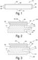
- Figure 3shows a panel edge 102 comprising the second profile 109.
- the second profile 109comprises two tongues 112, 113 and a groove 114.
- the groove 114is provided in the direction perpendicular to the panel surface 150 between the two tongues 112, 113.
- Each of the two tongues 112, 113 and the groove 114extend perpendicularly to the edge comprising the second profile 109.
- the two tongues 112, 113 of the second profile 109are tapered towards their distal ends.
- the two tongues 112, 113extend perpendicularly to the panel edge to the same plane 162 perpendicular to the panel surface 250 and parallel with the panel edge 102.
- the panel edge 102 comprising the second profile 109is provided with an undercut 160.
- the undercut 160is provided closer to the panel surface 150 than the tongue 112 of the two tongues 112, 113 closest to the panel surface 150.
- the undercut 160is provided adjacent to the tongue 112 closest to the panel surface 150.
- Such undercuthas the benefit that glue used to glue panel edges together can be collected in the undercut especially when excessive amount of glue would have been used.
- Figure 4shows a panel edge 103 comprising the third profile 110.
- the third profile 110comprises a groove 116.
- the groove 116extends perpendicularly to the edge comprising the third profile 110.
- the groove 116 of the third profile 110is a segmented groove, comprising an upper groove section 130 closest to the surface 250 of the panel, a middle groove section 131 and a bottom groove section 132.
- the middle groove section 131extends more proximal into the panel than the upper groove section 130 and the bottom groove section 132.
- the middle groove section 131is provided for receiving the first tongue 111 of the first profile 108 of another such panel.
- the upper groove section 130 and the bottom groove section 132are provided each for receiving a tongue 112, 113 of the second profile 109 of another such panel.
- the middle groove section 131comprises an upper lip 140 and a bottom lip 141.
- the upper groove section 130comprises an upper lip 143.
- the upper groove section 130extends at its bottom into 131 over part of its length parallel with the panel surface into the middle groove section.
- the bottom groove section 132comprises a bottom lip 144 and extends at its upper side over part of its length as seen parallel with the panel surface into the middle groove section 131.
- the upper groove section 130 and the bottom groove section 132have the same height and extend the same distance into the panel edge where they are provided.
- the panel 101 of the example showncomprises a decorative wood layer 170 and one or a plurality of supporting layers 171, in the example shown wood supporting layers.
- the tongues 111, 112, 113 and grooves 152, 153, 114, 116 of the first profile 108, the second profile 109 and the third profile 110are provided integrally in the one or plurality of supporting layers 171 and do not extend into the decorative wood layer 170.
- each of the first edge 102, the second edge 105, the third edge 103 and the fourth edge 106are provided closer to the panel surface 150 than the first profile 108, the second profile 109 and the third profile 110 with a closing plane 125.
- the closing planes 125are provided substantially perpendicular to the panel surface 150. In coupled condition of two panels the closing planes of the panel edges coupled to each other contact each other or are positioned closely to each other.
- none of the first profile 108, the second profile 109 and the third profile 110are provided with mechanical locking means that would prevent that two such panels coupled at their edges could shift away from each other in the direction perpendicular to the coupled panel edges.
- Each of the examples shown of the first profile 108, the second profile 109 and the third profile 110can be provided by one profiling. No complex milling equipment nor complicated manufacturing process is required.
- Figures 5 - 7show the panel edges and profiles shown in figures 2-4 coupled to each other.
- Figure 5shows a panel edge comprising the first profile 108 coupled to a panel edge comprising the second profile 109.
- Figure 6shows a panel edge comprising the first profile 108 coupled to a panel edge comprising the third profile 110.
- Figure 7shows a panel edge comprising the second profile 109 coupled to a panel edge comprising the third profile 110.
- the tongues 111, 112, 113 and grooves 152, 153, 114, 116 of the first profile 108, the second profile 109 and the third profile 110are configured such that the panel edge or edges provided with the first profile 108 can be coupled onto the panel edge or panel edges provided with the second profile 109 of another such panel as well as onto the panel edge or panel edges provided with the third profile 110 of another such panel, and such that the panel edge or edges provided with the second profile 109 can be coupled onto the panel edge or panel edges provided with the third profile 110 of another such panel.
- a lockingis provided of the coupled edges in the direction perpendicular to the surface of the coupled panels.
- the first profile 108 and the second profile 109are configured such that the first tongue 111 of the first profile 108 can be inserted in the groove 114 of the second profile 109 of another such panel, and such that each of the two tongues 112, 113 of the second profile 109 of the another such panel can be inserted in a groove 152, 153 of the first groove 152 and the second groove 153 of the first profile 108 of the panel, such that a locking is obtained in the direction perpendicular to the panel surface of the so coupled panel edges.
- the first profile 108 and the third profile 110are configured such that the first tongue 111 of the panel can be inserted in the groove 116 of the third profile 110 of another such panel, such that a locking is obtained in the direction perpendicular to the panel surface of the so coupled panel edges.
- the second profile 109 and the third profile 110are configured such that each of the two tongues 112, 113 of the second profile 109 of the panel can be inserted in the groove 116 of the third profile of another such panel, such that a locking is obtained in the direction perpendicular to the panel surface of the so coupled panel edges.
- the panel according to the invention as illustrated in figures 1 - 7can be installed in a plurality of installation patterns. This is possible as both short edges 105, 106 of the panel can be coupled at any position along the length of each of the two long panel edges 102, 103.
- Figures 8 , 9 and 10show examples of installation patterns that are possible with the panel of the invention illustrated in figures 1-7 .
- Figure 8shows a herringbone pattern obtained with the panels 101 of figure 1 .
- Figure 9shows a double herringbone pattern obtained with the panels 101 of figure 1 .
- Figure 10shows a block pattern obtained with the panels 101 of figure 1 .
Landscapes
- Engineering & Computer Science (AREA)
- Architecture (AREA)
- Civil Engineering (AREA)
- Structural Engineering (AREA)
- Finishing Walls (AREA)
Description
- The invention relates to panels, and particularly to decorative panels. The invention relates more specifically to floor panels and wall panels.
- Rectangular decorative panels are known that have tongue and groove coupling parts at their pairs of opposite edges. These panels can be installed in rows.
- For complex installation patterns, such as e.g. herringbone installation patterns, two types of panels are required. An example of sets of panels that can be installed in herringbone configuration are disclosed in
US1787027 andDE 202019101603 U1 . EP3128102A1 andEP 1730366 B1 disclose panels with tongue and groove coupling means such that only one type of panels is required to install a herringbone pattern. The panels ofEP3128102A1 have the disadvantage that special equipment is required for their manufacturing, and that their manufacturing requires a complex operation.EP1730366 B1 discloses panel according to the preamble of claim 1.- It is an objective of the invention to provide panels with tongue and groove coupling means such that a variety of complex installation patterns - such as herringbone patterns - are possible using only one type of panels.
- It is an objective of the invention to provide such panels that can be easily manufactured with a minimum of manufacturing operations, and that do not require complex manufacturing equipment.
- The invention is described by the independent claim(s). The dependent claims provide preferred embodiments of the invention.
- The first aspect of the invention is a panel. The panel is rectangular, oblong or square. The panel comprises a first pair of opposing edges, wherein the first pair of opposing edges comprises a first edge and a third edge. The panel comprises a second pair of opposing edges, wherein the second pair of opposing edges comprises a second edge and a fourth edge. Each of the first edge, the second edge, the third edge and the fourth edge comprises a profile selected from a first profile, a second profile and a third profile. The first profile comprises a first tongue, a first groove and a second groove; wherein the first tongue is provided in the direction perpendicular to the panel surface between the first groove and the second groove, wherein the first groove is provided closer to the panel surface than the second groove, and wherein the second groove comprises a bottom lip. Preferably, the first tongue extends perpendicularly to the edge comprising the first profile.
- The second profile comprises two tongues and a groove, wherein the groove is provided in the direction perpendicular to the panel surface between the two tongues. Preferably, each of the two tongues and the groove extend perpendicularly to the edge comprising second profile.
- The third profile comprises a groove. Preferably, the groove extends perpendicularly to the edge comprising the third profile.
- Each of the first profile, the second profile and the third profile extend continuously and along the full length of the edge(s) where they are provided. Two opposite edges of the first pair of opposite edges or the second pair of opposite edges are each provided with a first profile, or with a second profile or with a third profile.
- The tongues and grooves of the first profile, the second profile and the third profile are configured such that the panel edge or edges provided with the first profile can be coupled onto the panel edge or panel edges provided with the second profile of another such panel as well as onto the panel edge or panel edges provided with the third profile of another such panel; and such that the panel edge or edges provided with the second profile can be coupled onto the panel edge or panel edges provided with the third profile of another such panel, wherein in each of these coupled configurations a locking is provided of the coupled edges in the direction perpendicular to the surface of the coupled panels.
- It is a benefit that each of the first profile, the second profile and the third profile can be provided by one profiling only. Therefore, the manufacturing of the panels is facilitated as a minimum amount of tooling is required and no complex machinery is required for milling the panel edges. Using continuous profiles along the full length of the panel edges - with a constant cross section of the profiles - facilitates manufacturing as the milling machines do not need special control mechanisms to vary the profile along the length of the panel edge.
- The panels provide a large variety of installation patterns that can be made with the panels. E.g. herringbone patterns, double herringbone patterns and block patterns can all be made with the same panels without adaptations being required.
- The presence of the bottom lip at the second groove allows that coupled panel edges wherein one of the coupled panel edges comprises the first profile join each other closely at the bottom of the panel with no or minimal gap between the panel edges at the bottom of the coupled panels.
- In a preferred embodiment of the invention, the first profile and the second profile are configured such that the first tongue of the first profile of the panel can be inserted in the groove of the second profile of another such panel, and such that each of the two tongues of the second profile of the another such panel can be inserted in a groove of the first groove and the second groove of the first profile of the panel, such that a locking is obtained in the direction perpendicular to the panel surface of the so coupled panel edges; wherein the first profile and the third profile are configured such that the first tongue of the panel can be inserted in the groove of the third profile of another such panel, such that a locking is obtained in the direction perpendicular to the panel surface of the so coupled panel edges; and wherein the second profile and the third profile are configured such that each of the two tongues of the second profile of the panel can be inserted in the groove of the third profile of another such panel, such that a locking is obtained in the direction perpendicular to the panel surface of the so coupled panel edges.
- Such embodiments provide a very effective locking in the direction perpendicular to the coupled panel edges.
- Preferably, the first tongue is tapered towards its distal end, optionally the taper can be linear or curved or a combination of curved and linear.
- Preferably at least one, and more preferably both of the two tongues of the second profile is/are tapered towards its/their distal end(s).
- Tapered tongues (and corresponding tapered grooves) can easily be manufactured and facilitate the insertion and locking of the tongues in the grooves when installing the panels in a covering.
- The first profile, the second profile and the third profile preferably have a constant cross section along the full length of the panel edge(s) where they are provided. Such embodiments facilitate the manufacturing process of the panel edges, as no complex tooling is required in the manufacturing operation.
- In a preferred embodiment of the invention, the groove of the third profile is a segmented groove, wherein the segmented groove comprises an upper groove section closest to the surface of the panel, a middle groove section and a bottom groove section, wherein the middle groove section extends more proximal into the panel than the upper groove section and the bottom groove section; wherein the middle groove section is provided for receiving the first tongue of the first profile of another such panel; wherein the upper groove section and the bottom groove section are provided each for receiving a tongue of the two tongues of the second profile of another such panel.
- Such panels provide excellent locking in the direction perpendicular to the panel surface when a panel edge comprising the third profile is coupled to a panel edge comprising the first profile or the second profile.
- More preferably, the middle groove section comprises an upper lip and a bottom lip, wherein the upper groove section comprises an upper lip, wherein the upper groove section extends at its bottom over part of its length as seen parallel with the panel surface into the middle groove section, wherein the bottom groove section comprises a bottom lip and extends at its upper side over part of its length as seen parallel with the panel surface into the middle groove section.
- Such embodiment provide excellent locking in the direction perpendicular to the panel surface when a panel edge comprising the third profile is coupled to a panel edge comprising the first profile or the second profile.
- In a preferred embodiment of the invention, each of the first edge, the second edge, the third edge and the fourth edge are provided closer to the panel surface than the first profile, the second profile and the third profile with a closing plane, wherein the closing planes are provided substantially perpendicular to the panel surface, and wherein in coupled condition of two panels the closing planes of the panel edges coupled to each other contact each other or are positioned closely to each other.
- It is the intention that closing planes of coupled panels contact each other. However, due to manufacturing tolerance it cannot be excluded that a small gap occurs between the closing planes of coupled panels.
- Preferably, the upper groove section and the bottom groove section have the same height and/or extend the same distance - as measured from the closing plane of the panel - into the panel edge.
- It is a benefit of such embodiments that the tongues of the second profile can be made with the same height, this means that none of them is weaker than the other one. Therefore, the risk is minimized that the second profile is damaged during transport, storage or installation of the panels.
- Preferably, none of the first profile, the second profile and the third profile are provided with mechanical locking means that would prevent that two such panels coupled at their edges could shift away from each other in the direction perpendicular to the coupled panel edges.
- Such panels have less complex coupling profiles and are therefore more easy to manufacture as less complex milling equipment is required. Furthermore, there is less risk of breakage of the profiles or of part of it during manufacturing, transport or installation as the first profile, the second profile and the third profile can be made sufficiently sturdy.
- The first tongue preferably has a convex cross section in the direction perpendicular to the panel edge where the first profile is provided. This makes the first profile easy to produce, and minimizes the risk of breakage or damage of the first tongue in manufacturing, transport and installation.
- A preferred panel is rectangular and oblong, wherein both short panel edges are provided with the first profile or with the second profile or with the third profile, wherein both short edges are configured such that they can be coupled at any position along the length of any one of both long edges.
- Such panels allow installation in herringbone configuration, as well as in a number of other complex configurations.
- Preferably, the lower lip of the first groove is provided by the first tongue; and the upper lip of the second groove is provided by the first tongue.
- Such panels are easy to produce, as the first profile has a more simple configuration.
- Preferably, the first groove extends into the panel to the same depth parallel with the panel surface as the second groove.
- It means that both tongues of the second profile can be made to have the same length, which makes them less vulnerable in transport and installation.
- Preferably, the first groove and the second groove have the same height.
- It means that both tongues of the second profile can have the same thickness, such that there is no smaller one which would be more vulnerable in production, transport and installation.
- In a preferred embodiment, the two tongues of the second profile extend perpendicularly to the panel edge to the same plane perpendicular to the panel surface and parallel with the panel edge.
- It is a benefit of this embodiment that the second profile is less vulnerable in production, transport and installation.
- In a preferred embodiment, the panel edge(s) comprising the second profile is/are provided with an undercut, wherein the undercut is provided closer to the panel surface than the tongue of the tongues of the second profile closest to the panel surface. More preferably, the undercut is provided adjacent to the tongue of the tongues of the second profile closest to the panel surface.
- The undercut has the benefit that glue used to glue panel edges together - wherein one of the panel edges comprises the second profile - can be collected in the undercut when excessive amount of glue would have been used.
- In a preferred embodiment, the panel comprises a decorative wood layer and one or a plurality of supporting layers.
- Preferably, the tongues and grooves of the first profile, the second profile and the third profile are provided integrally in the one or plurality of supporting layers and do not extend into the decorative wood layer. Such embodiments allow to make optimum choices for the layers of the panel, e.g. to optimize the strength of the panel coupling. The supporting layers are preferably one or a plurality of wood layers and/or wood based layers such as oriented strand board, plywood, fiber board or particle board.
- The second aspect of the invention is a set of panels comprising and preferably consisting of panels as in any embodiment of the first aspect of the invention.
- The third aspect of the invention is a floor- or wall covering comprising a set of panels as in the second aspect of the invention or comprising a plurality of panels as in any embodiment of the first aspect of the invention, wherein the panels are installed in a configuration wherein at least some of the panels make a 90° angle relative to each other; e.g. wherein the panels are installed in a herringbone configuration or in a double herringbone configuration.
- With the intention of better showing the characteristics of the invention, hereafter, as an example without any limitative character, preferred embodiments are described, with reference to the accompanying drawings, wherein:
Figure 1 shows a panel according to the invention;Figure 2 shows a panel edge comprising the first profile;Figure 3 shows a panel edge comprising the second profile;Figure 4 shows a panel edge comprising the third profile;Figure 5 shows a panel edge comprising the first profile coupled to a panel edge comprising the second profile;Figure 6 shows a panel edge comprising the first profile coupled to a panel edge comprising the third profile;Figure 7 shows a panel edge comprising the second profile coupled to a panel edge comprising the third profile;Figure 8 illustrates a herringbone pattern obtained with the panels offigure 1 ;Figure 9 illustrates a double herringbone pattern obtained with the panels offigure 1 ;Figure 10 illustrates a block pattern obtained with the panels offigure 1 .Figure 1 shows apanel 101 according to the invention. Thepanel 101 is rectangular and oblong. The panel comprises a first pair of opposingedges first edge 102 and athird edge 103, in the example shown provided at the long edges of the panel. The panel comprises a second pair of opposingedges second edge 105 and afourth edge 106, provided at the short edges of the panel.- In the example shown in
figure 1 , thesecond edge 105 and thefourth edge 106 are provided with afirst profile 108. Thefirst edge 102 is provided with asecond profile 109, and thethird edge 103 is provided with athird profile 110. Each of thefirst profile 108, thesecond profile 109 and thethird profile 110 extend continuously and along the full length of the edge(s) where they are provided. Each of thefirst profile 108, thesecond profile 109 and thethird profile 110 have a constant cross section along the full length of the panel edge(s) where they are provided.Figures 2-4 explain the details of thefirst profile 108, thesecond profile 109 and thethird profile 110 as used in thepanel 101 offigure 1 . Figure 2 shows apanel edge first profile 108. Thefirst profile 108 comprises afirst tongue 111, afirst groove 152 and asecond groove 153. Thefirst tongue 111 is provided in the direction perpendicular to thepanel surface 150 between thefirst groove 152 and thesecond groove 153. Thefirst groove 152 is provided closer to thepanel surface 150 than thesecond groove 153. Thesecond groove 153 comprises abottom lip 154. Thefirst tongue 111 extends perpendicularly to the edge comprising thefirst profile 108.- The
lower lip 155 of thefirst groove 152 is provided by thefirst tongue 111. Theupper lip 156 of thesecond groove 153 is provided by the first tongue 11 1.Thefirst groove 152 extends parallel with the panel surface into the panel to the same depth as thesecond groove 153. - The
first groove 152 and thesecond groove 153 have the same height. - In the example shown, the
first tongue 111 is tapered towards its distal end. Thefirst tongue 111 has a convex cross section in the direction perpendicular to the panel edge where the first profile is provided. Figure 3 shows apanel edge 102 comprising thesecond profile 109. Thesecond profile 109 comprises twotongues groove 114. Thegroove 114 is provided in the direction perpendicular to thepanel surface 150 between the twotongues tongues groove 114 extend perpendicularly to the edge comprising thesecond profile 109. In the example shown, the twotongues second profile 109 are tapered towards their distal ends.- The two
tongues same plane 162 perpendicular to the panel surface 250 and parallel with thepanel edge 102. - The
panel edge 102 comprising thesecond profile 109 is provided with an undercut 160. The undercut 160 is provided closer to thepanel surface 150 than thetongue 112 of the twotongues panel surface 150. The undercut 160 is provided adjacent to thetongue 112 closest to thepanel surface 150. Such undercut has the benefit that glue used to glue panel edges together can be collected in the undercut especially when excessive amount of glue would have been used. Figure 4 shows apanel edge 103 comprising thethird profile 110. Thethird profile 110 comprises agroove 116. Thegroove 116 extends perpendicularly to the edge comprising thethird profile 110. Thegroove 116 of thethird profile 110 is a segmented groove, comprising anupper groove section 130 closest to the surface 250 of the panel, amiddle groove section 131 and abottom groove section 132. Themiddle groove section 131 extends more proximal into the panel than theupper groove section 130 and thebottom groove section 132. Themiddle groove section 131 is provided for receiving thefirst tongue 111 of thefirst profile 108 of another such panel. Theupper groove section 130 and thebottom groove section 132 are provided each for receiving atongue second profile 109 of another such panel.- The
middle groove section 131 comprises anupper lip 140 and abottom lip 141. Theupper groove section 130 comprises anupper lip 143. Theupper groove section 130 extends at its bottom into 131 over part of its length parallel with the panel surface into the middle groove section. Thebottom groove section 132 comprises abottom lip 144 and extends at its upper side over part of its length as seen parallel with the panel surface into themiddle groove section 131. - In the example shown, the
upper groove section 130 and thebottom groove section 132 have the same height and extend the same distance into the panel edge where they are provided. - The
panel 101 of the example shown comprises adecorative wood layer 170 and one or a plurality of supportinglayers 171, in the example shown wood supporting layers. Thetongues grooves first profile 108, thesecond profile 109 and thethird profile 110 are provided integrally in the one or plurality of supportinglayers 171 and do not extend into thedecorative wood layer 170. - In the examples shown, each of the
first edge 102, thesecond edge 105, thethird edge 103 and thefourth edge 106 are provided closer to thepanel surface 150 than thefirst profile 108, thesecond profile 109 and thethird profile 110 with aclosing plane 125. The closing planes 125 are provided substantially perpendicular to thepanel surface 150. In coupled condition of two panels the closing planes of the panel edges coupled to each other contact each other or are positioned closely to each other. - In the examples shown, none of the
first profile 108, thesecond profile 109 and thethird profile 110 are provided with mechanical locking means that would prevent that two such panels coupled at their edges could shift away from each other in the direction perpendicular to the coupled panel edges. - Each of the examples shown of the
first profile 108, thesecond profile 109 and thethird profile 110 can be provided by one profiling. No complex milling equipment nor complicated manufacturing process is required. Figures 5 - 7 show the panel edges and profiles shown infigures 2-4 coupled to each other.Figure 5 shows a panel edge comprising thefirst profile 108 coupled to a panel edge comprising thesecond profile 109.Figure 6 shows a panel edge comprising thefirst profile 108 coupled to a panel edge comprising thethird profile 110.Figure 7 shows a panel edge comprising thesecond profile 109 coupled to a panel edge comprising thethird profile 110. Thetongues grooves first profile 108, thesecond profile 109 and thethird profile 110 are configured such that the panel edge or edges provided with thefirst profile 108 can be coupled onto the panel edge or panel edges provided with thesecond profile 109 of another such panel as well as onto the panel edge or panel edges provided with thethird profile 110 of another such panel, and such that the panel edge or edges provided with thesecond profile 109 can be coupled onto the panel edge or panel edges provided with thethird profile 110 of another such panel. In each of these coupled configurations a locking is provided of the coupled edges in the direction perpendicular to the surface of the coupled panels.- As becomes clear from
figure 5 , thefirst profile 108 and thesecond profile 109 are configured such that thefirst tongue 111 of thefirst profile 108 can be inserted in thegroove 114 of thesecond profile 109 of another such panel, and such that each of the twotongues second profile 109 of the another such panel can be inserted in agroove first groove 152 and thesecond groove 153 of thefirst profile 108 of the panel, such that a locking is obtained in the direction perpendicular to the panel surface of the so coupled panel edges. - As becomes clear from
figure 6 , thefirst profile 108 and thethird profile 110 are configured such that thefirst tongue 111 of the panel can be inserted in thegroove 116 of thethird profile 110 of another such panel, such that a locking is obtained in the direction perpendicular to the panel surface of the so coupled panel edges. - As becomes clear from
figure 7 , thesecond profile 109 and thethird profile 110 are configured such that each of the twotongues second profile 109 of the panel can be inserted in thegroove 116 of the third profile of another such panel, such that a locking is obtained in the direction perpendicular to the panel surface of the so coupled panel edges. - The panel according to the invention as illustrated in
figures 1 - 7 can be installed in a plurality of installation patterns. This is possible as bothshort edges Figures 8 ,9 and 10 show examples of installation patterns that are possible with the panel of the invention illustrated infigures 1-7 .Figure 8 shows a herringbone pattern obtained with thepanels 101 offigure 1 .Figure 9 shows a double herringbone pattern obtained with thepanels 101 offigure 1 .Figure 10 shows a block pattern obtained with thepanels 101 offigure 1 .- The present invention is in no way limited to the embodiments described as an example and represented in the figures, on the contrary may such panel be realized in various forms and dimensions, without leaving the scope of the invention as defined by the claims.
Claims (15)
- Panel (101), wherein the panel is rectangular, oblong or square,wherein the panel comprises a first pair of opposing edges (102, 103), wherein the first pair of opposing edges comprises a first edge (102) and a third edge (103),wherein the panel comprises a second pair of opposing edges (105, 106), wherein the second pair of opposing edges comprises a second edge (105) and a fourth edge (106), wherein each of the first edge, the second edge, the third edge and the fourth edge comprises a profile selected from a first profile (108), a second profile (109) and a third profile (110),wherein each of said first, second and third profiles is provided along at least one of said edges;wherein each of the first profile, the second profile and the third profile extend continuously and along the full length of the edge(s) where they are provided;wherein two opposite edges of the first pair of opposite edges or the second pair of opposite edges are each provided with a first profile, or with a second profile or with a third profile;wherein the profiles are provided with tongues adapted to be inserted into grooves,characterized in that- the first profile (108) comprises a first tongue (111), a first groove (152) and a second groove (153), wherein the first tongue is provided in the direction perpendicular to the panel surface (150) between the first groove and the second groove, wherein the first groove is provided closer to the panel surface (150) than the second groove, wherein the second groove comprises a bottom lip (154),-in that the second profile (109) comprises two tongues (112, 113) and a groove (114), wherein the groove (114) is provided in the direction perpendicular to the panel surface (150) between the two tongues (112, 113),- andin that the third profile (110) comprises a groove (116),wherein the tongues (111, 112, 113) and grooves (152, 153, 114, 116) of the first profile (108), the second profile (109) and the third profile (110) are configured such that the panel edge or edges provided with the first profile (108) can be coupled onto the panel edge or panel edges provided with the second profile (109) of another such panel as well as onto the panel edge or panel edges provided with the third profile (110) of another such panel,and such that the panel edge or edges provided with the second profile (109) can be coupled onto the panel edge or panel edges provided with the third profile (110) of another such panel,wherein in each of these coupled configurations a locking is provided of the coupled edges in the direction perpendicular to the surface of the coupled panels.
- Panel as in claim 1, wherein the first profile (108) and the second profile (109) are configured such that the first tongue (111) of the first profile of the panel can be inserted in the groove (114) of the second profile (109) of another such panel, and such that each of the two tongues (112, 113) of the second profile (109) of the another such panel can be inserted in a groove (152, 153) of the first groove (152) and the second groove (153) of the first profile (108) of the panel, such that a locking is obtained in the direction perpendicular to the panel surface of the so coupled panel edges; and wherein the first profile (108) and the third profile (110) are configured such that the first tongue (111) of the panel can be inserted in the groove (116) of the third profile (110) of another such panel, such that a locking is obtained in the direction perpendicular to the panel surface of the so coupled panel edges; and
wherein the second profile (109) and the third profile (110) are configured such that each of the two tongues (112, 113) of the second profile (109) of the panel can be inserted in the groove (116) of the third profile of another such panel, such that a locking is obtained in the direction perpendicular to the panel surface of the so coupled panel edges. - Panel as in any of the preceding claims, wherein the first tongue (111) is tapered towards its distal end, optionally the taper can be linear or curved or a combination of curved and linear; and/or
wherein at least one and preferably both of the two tongues (112, 113) of the second profile (109) is/are tapered towards its/their distal end(s) - Panel as in any of the preceding claims, wherein the groove (116) of the third profile (110) is a segmented groove, wherein the segmented groove comprises an upper groove section (130) closest to the surface of the panel, a middle groove section (131) and a bottom groove section (132), wherein the middle groove section (131) extends more proximal into the panel than the upper groove section (130) and the bottom groove section (132);wherein the middle groove section (131) is provided for receiving the first tongue (111) of the first profile (108) of another such panel;wherein the upper groove section (130) and the bottom groove section (132) are provided each for receiving a tongue (112, 113) of the two tongues of the second profile (109) of another such panel.
- Panel as in claim 4, wherein the middle groove section (131) comprises an upper lip (140) and a bottom lip (141), wherein the upper groove section (130) comprises an upper lip (143), wherein the upper groove section (130) extends at its bottom over part of its length as seen parallel with the panel surface (150) into the middle groove section (131), wherein the bottom groove section (132) comprises a bottom lip (144) and extends at its upper side over part of its length as seen parallel with the panel surface (150) into the middle groove section (131).
- Panel as in any of the preceding claims, wherein each of the first edge (102), the second edge (105), the third edge (103) and the fourth edge (106) are provided closer to the panel surface (150) than the first profile (108), the second profile (109) and the third profile (110) with a closing plane (125), wherein the closing planes (125) are provided substantially perpendicular to the panel surface (150), and wherein in coupled condition of two panels the closing planes of the panel edges coupled to each other contact each other or are positioned closely to each other.
- Panel as in claims 4 or 5, and as in claim 6, wherein the upper groove section (130) and the bottom groove section (132) have the same height and/or extend the same distance - as measured from the closing plane (125) of the panel - into the panel edge.
- Panel as in any of the preceding claims, wherein none of the first profile (108), the second profile (109) and the third profile (110) are provided with mechanical locking means that would prevent that two such panels coupled at their edges could shift away from each other in the direction perpendicular to the coupled panel edges.
- Panel as in any of the preceding claims, wherein the first tongue (111) has a convex cross section.
- Panel as in any of the preceding claims, wherein the panel is rectangular and oblong, wherein both short panel edges are provided with the first profile (108) or with the second profile (109) or with the third profile (110), wherein both short edges are configured such that they can be coupled at any position along the length of any one of both long edges.
- Panel as in any of the preceding claims, wherein the lower lip (155) of the first groove (152) is provided by the first tongue (111) and wherein the upper lip (156) of the second groove (153) is provided by the first tongue (111).
- Panel as in any of the preceding claims, wherein the two tongues (112, 113) of the second profile extend perpendicularly to the panel edge to the same plane perpendicular to the panel surface and parallel with the panel edge.
- Panel as in any of the preceding claims, wherein the panel edge(s) comprising the second profile is/are provided with an undercut (160), wherein the undercut is provided closer to the panel surface (150) than the tongue of the tongues of the second profile closest to the panel surface, preferably wherein the undercut is provided adjacent to the tongue of the tongues of the second profile closest to the panel surface.
- Panel as in any of the preceding claims, wherein the panel comprises a decorative wood layer (170) and one or a plurality of supporting layers (171), preferably wherein the tongues (111, 112, 113) and grooves (152, 153, 114, 116) of the first profile (108), the second profile (109) and the third profile (110) are provided integrally in the one or plurality of supporting layers (171) and do not extend into the decorative wood layer (170).
- Floor- or wall covering comprising a plurality of panels as in any of the preceding claims 1 - 14, wherein the panels are installed in a configuration wherein at least some of the panels make a 90° angle relative to each other; e.g. wherein the panels are installed in a herringbone configuration or in a double herringbone configuration.
Priority Applications (4)
| Application Number | Priority Date | Filing Date | Title |
|---|---|---|---|
| EP21172269.9AEP4086408B1 (en) | 2021-05-05 | 2021-05-05 | Panel |
| US18/558,472US20240240467A1 (en) | 2021-05-05 | 2022-05-02 | Panel |
| EP22722356.7AEP4334547A1 (en) | 2021-05-05 | 2022-05-02 | Panel |
| PCT/IB2022/054026WO2022234424A1 (en) | 2021-05-05 | 2022-05-02 | Panel |
Applications Claiming Priority (1)
| Application Number | Priority Date | Filing Date | Title |
|---|---|---|---|
| EP21172269.9AEP4086408B1 (en) | 2021-05-05 | 2021-05-05 | Panel |
Publications (2)
| Publication Number | Publication Date |
|---|---|
| EP4086408A1 EP4086408A1 (en) | 2022-11-09 |
| EP4086408B1true EP4086408B1 (en) | 2024-10-16 |
Family
ID=75825530
Family Applications (2)
| Application Number | Title | Priority Date | Filing Date |
|---|---|---|---|
| EP21172269.9AActiveEP4086408B1 (en) | 2021-05-05 | 2021-05-05 | Panel |
| EP22722356.7APendingEP4334547A1 (en) | 2021-05-05 | 2022-05-02 | Panel |
Family Applications After (1)
| Application Number | Title | Priority Date | Filing Date |
|---|---|---|---|
| EP22722356.7APendingEP4334547A1 (en) | 2021-05-05 | 2022-05-02 | Panel |
Country Status (3)
| Country | Link |
|---|---|
| US (1) | US20240240467A1 (en) |
| EP (2) | EP4086408B1 (en) |
| WO (1) | WO2022234424A1 (en) |
Families Citing this family (1)
| Publication number | Priority date | Publication date | Assignee | Title |
|---|---|---|---|---|
| NL2003019C2 (en)* | 2009-06-12 | 2010-12-15 | 4Sight Innovation Bv | FLOOR PANEL AND FLOOR COVERAGE CONSISING OF MULTIPLE OF SUCH FLOOR PANELS. |
Citations (1)
| Publication number | Priority date | Publication date | Assignee | Title |
|---|---|---|---|---|
| EP4257775A1 (en)* | 2020-05-05 | 2023-10-11 | Franz Eschlbeck | Panel |
Family Cites Families (14)
| Publication number | Priority date | Publication date | Assignee | Title |
|---|---|---|---|---|
| US1787027A (en) | 1929-02-20 | 1930-12-30 | Wasleff Alex | Herringbone flooring |
| DE29803708U1 (en)* | 1997-10-04 | 1998-05-28 | Shen Technical Company Ltd., Nikosia | Panel, in particular for floor coverings |
| DE10008108C1 (en)* | 2000-02-22 | 2001-05-23 | Kronotec Ag | Panel, especially a floorboard panel, comprises a tongue on one end and a groove on the other end provided with locking devices which prevent movement against the connection direction of two interlocked panels |
| US6823638B2 (en)* | 2001-06-27 | 2004-11-30 | Pergo (Europe) Ab | High friction joint, and interlocking joints for forming a generally planar surface, and method of assembling the same |
| DE10206877B4 (en)* | 2002-02-18 | 2004-02-05 | E.F.P. Floor Products Fussböden GmbH | Panel, especially floor panel |
| ATE439988T1 (en)* | 2004-01-16 | 2009-09-15 | Berry Finance Nv | PANEL AND METHOD AND DEVICE FOR PRODUCING SAME |
| DE102004028757B4 (en)* | 2004-04-02 | 2007-11-15 | hülsta-werke Hüls GmbH & Co. KG. | Panel element for floor, wall and / or ceiling installation and method for laying a covering, in particular a floor, wall and / or ceiling covering |
| US20060024465A1 (en)* | 2004-07-30 | 2006-02-02 | Jean Briere | Laminate flooring members |
| BE1017403A5 (en)* | 2006-12-21 | 2008-08-05 | Flooring Ind Ltd | FLOOR ELEMENT, LOCKING SYSTEM FOR FLOOR ELEMENTS, FLOOR COVERING AND METHOD FOR COMPOSING SUCH FLOOR ELEMENTS TO A FLOOR COVERING. |
| US9896851B1 (en)* | 2015-04-14 | 2018-02-20 | The Matworks Copmany LLC | Hard surface veneer and wood polymer composite flooring tile |
| EP3128102B1 (en) | 2015-08-06 | 2018-03-21 | Beugt Houtzagerij en Parketindustrie BV | Board for a wooden floor with a motif |
| BE1024723B1 (en)* | 2016-11-10 | 2018-06-11 | Ivc Bvba | Floor panel and method for manufacturing a floor panel. |
| DE202019101603U1 (en)* | 2019-03-20 | 2019-04-18 | Barlinek S.A. | Detachable connection of building panels for the installation of a mosaic surface covering |
| DE202020102526U1 (en)* | 2020-05-05 | 2021-08-06 | Franz Eschlbeck | Multi-profile panel |
- 2021
- 2021-05-05EPEP21172269.9Apatent/EP4086408B1/enactiveActive
- 2022
- 2022-05-02WOPCT/IB2022/054026patent/WO2022234424A1/ennot_activeCeased
- 2022-05-02USUS18/558,472patent/US20240240467A1/enactivePending
- 2022-05-02EPEP22722356.7Apatent/EP4334547A1/enactivePending
Patent Citations (1)
| Publication number | Priority date | Publication date | Assignee | Title |
|---|---|---|---|---|
| EP4257775A1 (en)* | 2020-05-05 | 2023-10-11 | Franz Eschlbeck | Panel |
Also Published As
| Publication number | Publication date |
|---|---|
| US20240240467A1 (en) | 2024-07-18 |
| EP4334547A1 (en) | 2024-03-13 |
| EP4086408A1 (en) | 2022-11-09 |
| WO2022234424A1 (en) | 2022-11-10 |
Similar Documents
| Publication | Publication Date | Title |
|---|---|---|
| EP1785547B1 (en) | Floor covering | |
| CA2723913C (en) | Panel, especially floor panel | |
| US8407963B2 (en) | Floor covering | |
| CN1113140C (en) | Floor board panel | |
| KR102558143B1 (en) | Joint system for floor panels | |
| US6769218B2 (en) | Floorboard and locking system therefor | |
| US8978335B2 (en) | Panel for mechanical connection with a further panel by means of pivoting | |
| US8499520B2 (en) | Floor covering | |
| EP2418336A1 (en) | An equipment for production of building panels | |
| KR20090028647A (en) | Floorboard and locking system | |
| US11834844B2 (en) | Flooring panel and a floor covering with such panel | |
| CA2656920A1 (en) | Locking system comprising a combination lock for panels | |
| EP4257775B1 (en) | Panel | |
| EP4086408B1 (en) | Panel | |
| EP4115031B1 (en) | Set of surface covering planks and method of connecting thereof | |
| WO2021045612A1 (en) | Floor panel and floor | |
| EP2112297B1 (en) | Connection for flooring panels | |
| EP4517025A2 (en) | Panel and floor covering comprising the same | |
| EP1203854A2 (en) | Tongue and groove connection for panels | |
| AU2006213930A1 (en) | Floor covering |
Legal Events
| Date | Code | Title | Description |
|---|---|---|---|
| PUAI | Public reference made under article 153(3) epc to a published international application that has entered the european phase | Free format text:ORIGINAL CODE: 0009012 | |
| STAA | Information on the status of an ep patent application or granted ep patent | Free format text:STATUS: THE APPLICATION HAS BEEN PUBLISHED | |
| AK | Designated contracting states | Kind code of ref document:A1 Designated state(s):AL AT BE BG CH CY CZ DE DK EE ES FI FR GB GR HR HU IE IS IT LI LT LU LV MC MK MT NL NO PL PT RO RS SE SI SK SM TR | |
| STAA | Information on the status of an ep patent application or granted ep patent | Free format text:STATUS: REQUEST FOR EXAMINATION WAS MADE | |
| 17P | Request for examination filed | Effective date:20230323 | |
| RBV | Designated contracting states (corrected) | Designated state(s):AL AT BE BG CH CY CZ DE DK EE ES FI FR GB GR HR HU IE IS IT LI LT LU LV MC MK MT NL NO PL PT RO RS SE SI SK SM TR | |
| GRAP | Despatch of communication of intention to grant a patent | Free format text:ORIGINAL CODE: EPIDOSNIGR1 | |
| STAA | Information on the status of an ep patent application or granted ep patent | Free format text:STATUS: GRANT OF PATENT IS INTENDED | |
| INTG | Intention to grant announced | Effective date:20240715 | |
| GRAS | Grant fee paid | Free format text:ORIGINAL CODE: EPIDOSNIGR3 | |
| GRAA | (expected) grant | Free format text:ORIGINAL CODE: 0009210 | |
| STAA | Information on the status of an ep patent application or granted ep patent | Free format text:STATUS: THE PATENT HAS BEEN GRANTED | |
| AK | Designated contracting states | Kind code of ref document:B1 Designated state(s):AL AT BE BG CH CY CZ DE DK EE ES FI FR GB GR HR HU IE IS IT LI LT LU LV MC MK MT NL NO PL PT RO RS SE SI SK SM TR | |
| P01 | Opt-out of the competence of the unified patent court (upc) registered | Free format text:CASE NUMBER: APP_51145/2024 Effective date:20240910 | |
| REG | Reference to a national code | Ref country code:GB Ref legal event code:FG4D | |
| REG | Reference to a national code | Ref country code:CH Ref legal event code:EP Ref country code:DE Ref legal event code:R096 Ref document number:602021020225 Country of ref document:DE | |
| REG | Reference to a national code | Ref country code:IE Ref legal event code:FG4D | |
| P02 | Opt-out of the competence of the unified patent court (upc) changed | Free format text:CASE NUMBER: APP_54447/2024 Effective date:20241002 | |
| REG | Reference to a national code | Ref country code:NL Ref legal event code:FP | |
| REG | Reference to a national code | Ref country code:LT Ref legal event code:MG9D | |
| REG | Reference to a national code | Ref country code:AT Ref legal event code:MK05 Ref document number:1733031 Country of ref document:AT Kind code of ref document:T Effective date:20241016 | |
| PG25 | Lapsed in a contracting state [announced via postgrant information from national office to epo] | Ref country code:PT Free format text:LAPSE BECAUSE OF FAILURE TO SUBMIT A TRANSLATION OF THE DESCRIPTION OR TO PAY THE FEE WITHIN THE PRESCRIBED TIME-LIMIT Effective date:20250217 Ref country code:HR Free format text:LAPSE BECAUSE OF FAILURE TO SUBMIT A TRANSLATION OF THE DESCRIPTION OR TO PAY THE FEE WITHIN THE PRESCRIBED TIME-LIMIT Effective date:20241016 Ref country code:IS Free format text:LAPSE BECAUSE OF FAILURE TO SUBMIT A TRANSLATION OF THE DESCRIPTION OR TO PAY THE FEE WITHIN THE PRESCRIBED TIME-LIMIT Effective date:20250216 | |
| PG25 | Lapsed in a contracting state [announced via postgrant information from national office to epo] | Ref country code:FI Free format text:LAPSE BECAUSE OF FAILURE TO SUBMIT A TRANSLATION OF THE DESCRIPTION OR TO PAY THE FEE WITHIN THE PRESCRIBED TIME-LIMIT Effective date:20241016 | |
| PG25 | Lapsed in a contracting state [announced via postgrant information from national office to epo] | Ref country code:BG Free format text:LAPSE BECAUSE OF FAILURE TO SUBMIT A TRANSLATION OF THE DESCRIPTION OR TO PAY THE FEE WITHIN THE PRESCRIBED TIME-LIMIT Effective date:20241016 | |
| PG25 | Lapsed in a contracting state [announced via postgrant information from national office to epo] | Ref country code:ES Free format text:LAPSE BECAUSE OF FAILURE TO SUBMIT A TRANSLATION OF THE DESCRIPTION OR TO PAY THE FEE WITHIN THE PRESCRIBED TIME-LIMIT Effective date:20241016 | |
| PG25 | Lapsed in a contracting state [announced via postgrant information from national office to epo] | Ref country code:NO Free format text:LAPSE BECAUSE OF FAILURE TO SUBMIT A TRANSLATION OF THE DESCRIPTION OR TO PAY THE FEE WITHIN THE PRESCRIBED TIME-LIMIT Effective date:20250116 | |
| PG25 | Lapsed in a contracting state [announced via postgrant information from national office to epo] | Ref country code:LV Free format text:LAPSE BECAUSE OF FAILURE TO SUBMIT A TRANSLATION OF THE DESCRIPTION OR TO PAY THE FEE WITHIN THE PRESCRIBED TIME-LIMIT Effective date:20241016 Ref country code:GR Free format text:LAPSE BECAUSE OF FAILURE TO SUBMIT A TRANSLATION OF THE DESCRIPTION OR TO PAY THE FEE WITHIN THE PRESCRIBED TIME-LIMIT Effective date:20250117 Ref country code:AT Free format text:LAPSE BECAUSE OF FAILURE TO SUBMIT A TRANSLATION OF THE DESCRIPTION OR TO PAY THE FEE WITHIN THE PRESCRIBED TIME-LIMIT Effective date:20241016 | |
| PG25 | Lapsed in a contracting state [announced via postgrant information from national office to epo] | Ref country code:PL Free format text:LAPSE BECAUSE OF FAILURE TO SUBMIT A TRANSLATION OF THE DESCRIPTION OR TO PAY THE FEE WITHIN THE PRESCRIBED TIME-LIMIT Effective date:20241016 | |
| PG25 | Lapsed in a contracting state [announced via postgrant information from national office to epo] | Ref country code:RS Free format text:LAPSE BECAUSE OF FAILURE TO SUBMIT A TRANSLATION OF THE DESCRIPTION OR TO PAY THE FEE WITHIN THE PRESCRIBED TIME-LIMIT Effective date:20250116 | |
| PGFP | Annual fee paid to national office [announced via postgrant information from national office to epo] | Ref country code:NL Payment date:20250526 Year of fee payment:5 | |
| PG25 | Lapsed in a contracting state [announced via postgrant information from national office to epo] | Ref country code:SM Free format text:LAPSE BECAUSE OF FAILURE TO SUBMIT A TRANSLATION OF THE DESCRIPTION OR TO PAY THE FEE WITHIN THE PRESCRIBED TIME-LIMIT Effective date:20241016 | |
| PGFP | Annual fee paid to national office [announced via postgrant information from national office to epo] | Ref country code:DE Payment date:20250529 Year of fee payment:5 | |
| PG25 | Lapsed in a contracting state [announced via postgrant information from national office to epo] | Ref country code:DK Free format text:LAPSE BECAUSE OF FAILURE TO SUBMIT A TRANSLATION OF THE DESCRIPTION OR TO PAY THE FEE WITHIN THE PRESCRIBED TIME-LIMIT Effective date:20241016 | |
| REG | Reference to a national code | Ref country code:DE Ref legal event code:R097 Ref document number:602021020225 Country of ref document:DE | |
| PG25 | Lapsed in a contracting state [announced via postgrant information from national office to epo] | Ref country code:EE Free format text:LAPSE BECAUSE OF FAILURE TO SUBMIT A TRANSLATION OF THE DESCRIPTION OR TO PAY THE FEE WITHIN THE PRESCRIBED TIME-LIMIT Effective date:20241016 | |
| PG25 | Lapsed in a contracting state [announced via postgrant information from national office to epo] | Ref country code:RO Free format text:LAPSE BECAUSE OF FAILURE TO SUBMIT A TRANSLATION OF THE DESCRIPTION OR TO PAY THE FEE WITHIN THE PRESCRIBED TIME-LIMIT Effective date:20241016 | |
| PG25 | Lapsed in a contracting state [announced via postgrant information from national office to epo] | Ref country code:SK Free format text:LAPSE BECAUSE OF FAILURE TO SUBMIT A TRANSLATION OF THE DESCRIPTION OR TO PAY THE FEE WITHIN THE PRESCRIBED TIME-LIMIT Effective date:20241016 | |
| PG25 | Lapsed in a contracting state [announced via postgrant information from national office to epo] | Ref country code:CZ Free format text:LAPSE BECAUSE OF FAILURE TO SUBMIT A TRANSLATION OF THE DESCRIPTION OR TO PAY THE FEE WITHIN THE PRESCRIBED TIME-LIMIT Effective date:20241016 | |
| PG25 | Lapsed in a contracting state [announced via postgrant information from national office to epo] | Ref country code:IT Free format text:LAPSE BECAUSE OF FAILURE TO SUBMIT A TRANSLATION OF THE DESCRIPTION OR TO PAY THE FEE WITHIN THE PRESCRIBED TIME-LIMIT Effective date:20241016 | |
| PLBE | No opposition filed within time limit | Free format text:ORIGINAL CODE: 0009261 | |
| STAA | Information on the status of an ep patent application or granted ep patent | Free format text:STATUS: NO OPPOSITION FILED WITHIN TIME LIMIT | |
| PG25 | Lapsed in a contracting state [announced via postgrant information from national office to epo] | Ref country code:SE Free format text:LAPSE BECAUSE OF FAILURE TO SUBMIT A TRANSLATION OF THE DESCRIPTION OR TO PAY THE FEE WITHIN THE PRESCRIBED TIME-LIMIT Effective date:20241016 | |
| 26N | No opposition filed | Effective date:20250717 |