EP4082481B1 - Fixation device having a flexure portion - Google Patents
Fixation device having a flexure portionDownload PDFInfo
- Publication number
- EP4082481B1 EP4082481B1EP22170956.1AEP22170956AEP4082481B1EP 4082481 B1EP4082481 B1EP 4082481B1EP 22170956 AEP22170956 AEP 22170956AEP 4082481 B1EP4082481 B1EP 4082481B1
- Authority
- EP
- European Patent Office
- Prior art keywords
- arm
- contact portion
- fixation device
- flexure
- leg
- Prior art date
- Legal status (The legal status is an assumption and is not a legal conclusion. Google has not performed a legal analysis and makes no representation as to the accuracy of the status listed.)
- Active
Links
Images


Classifications
- A—HUMAN NECESSITIES
- A61—MEDICAL OR VETERINARY SCIENCE; HYGIENE
- A61F—FILTERS IMPLANTABLE INTO BLOOD VESSELS; PROSTHESES; DEVICES PROVIDING PATENCY TO, OR PREVENTING COLLAPSING OF, TUBULAR STRUCTURES OF THE BODY, e.g. STENTS; ORTHOPAEDIC, NURSING OR CONTRACEPTIVE DEVICES; FOMENTATION; TREATMENT OR PROTECTION OF EYES OR EARS; BANDAGES, DRESSINGS OR ABSORBENT PADS; FIRST-AID KITS
- A61F2/00—Filters implantable into blood vessels; Prostheses, i.e. artificial substitutes or replacements for parts of the body; Appliances for connecting them with the body; Devices providing patency to, or preventing collapsing of, tubular structures of the body, e.g. stents
- A61F2/02—Prostheses implantable into the body
- A61F2/24—Heart valves ; Vascular valves, e.g. venous valves; Heart implants, e.g. passive devices for improving the function of the native valve or the heart muscle; Transmyocardial revascularisation [TMR] devices; Valves implantable in the body
- A61F2/2442—Annuloplasty rings or inserts for correcting the valve shape; Implants for improving the function of a native heart valve
- A61F2/2466—Delivery devices therefor
- A—HUMAN NECESSITIES
- A61—MEDICAL OR VETERINARY SCIENCE; HYGIENE
- A61F—FILTERS IMPLANTABLE INTO BLOOD VESSELS; PROSTHESES; DEVICES PROVIDING PATENCY TO, OR PREVENTING COLLAPSING OF, TUBULAR STRUCTURES OF THE BODY, e.g. STENTS; ORTHOPAEDIC, NURSING OR CONTRACEPTIVE DEVICES; FOMENTATION; TREATMENT OR PROTECTION OF EYES OR EARS; BANDAGES, DRESSINGS OR ABSORBENT PADS; FIRST-AID KITS
- A61F2/00—Filters implantable into blood vessels; Prostheses, i.e. artificial substitutes or replacements for parts of the body; Appliances for connecting them with the body; Devices providing patency to, or preventing collapsing of, tubular structures of the body, e.g. stents
- A61F2/02—Prostheses implantable into the body
- A61F2/24—Heart valves ; Vascular valves, e.g. venous valves; Heart implants, e.g. passive devices for improving the function of the native valve or the heart muscle; Transmyocardial revascularisation [TMR] devices; Valves implantable in the body
- A61F2/2442—Annuloplasty rings or inserts for correcting the valve shape; Implants for improving the function of a native heart valve
- A61F2/246—Devices for obstructing a leak through a native valve in a closed condition
- A—HUMAN NECESSITIES
- A61—MEDICAL OR VETERINARY SCIENCE; HYGIENE
- A61B—DIAGNOSIS; SURGERY; IDENTIFICATION
- A61B17/00—Surgical instruments, devices or methods
- A61B17/12—Surgical instruments, devices or methods for ligaturing or otherwise compressing tubular parts of the body, e.g. blood vessels or umbilical cord
- A61B17/122—Clamps or clips, e.g. for the umbilical cord
- A—HUMAN NECESSITIES
- A61—MEDICAL OR VETERINARY SCIENCE; HYGIENE
- A61F—FILTERS IMPLANTABLE INTO BLOOD VESSELS; PROSTHESES; DEVICES PROVIDING PATENCY TO, OR PREVENTING COLLAPSING OF, TUBULAR STRUCTURES OF THE BODY, e.g. STENTS; ORTHOPAEDIC, NURSING OR CONTRACEPTIVE DEVICES; FOMENTATION; TREATMENT OR PROTECTION OF EYES OR EARS; BANDAGES, DRESSINGS OR ABSORBENT PADS; FIRST-AID KITS
- A61F2220/00—Fixations or connections for prostheses classified in groups A61F2/00 - A61F2/26 or A61F2/82 or A61F9/00 or A61F11/00 or subgroups thereof
- A61F2220/0008—Fixation appliances for connecting prostheses to the body
- A61F2220/0016—Fixation appliances for connecting prostheses to the body with sharp anchoring protrusions, e.g. barbs, pins, spikes
- A—HUMAN NECESSITIES
- A61—MEDICAL OR VETERINARY SCIENCE; HYGIENE
- A61F—FILTERS IMPLANTABLE INTO BLOOD VESSELS; PROSTHESES; DEVICES PROVIDING PATENCY TO, OR PREVENTING COLLAPSING OF, TUBULAR STRUCTURES OF THE BODY, e.g. STENTS; ORTHOPAEDIC, NURSING OR CONTRACEPTIVE DEVICES; FOMENTATION; TREATMENT OR PROTECTION OF EYES OR EARS; BANDAGES, DRESSINGS OR ABSORBENT PADS; FIRST-AID KITS
- A61F2230/00—Geometry of prostheses classified in groups A61F2/00 - A61F2/26 or A61F2/82 or A61F9/00 or A61F11/00 or subgroups thereof
- A61F2230/0002—Two-dimensional shapes, e.g. cross-sections
- A61F2230/0017—Angular shapes
- A61F2230/0026—Angular shapes trapezoidal
- A—HUMAN NECESSITIES
- A61—MEDICAL OR VETERINARY SCIENCE; HYGIENE
- A61F—FILTERS IMPLANTABLE INTO BLOOD VESSELS; PROSTHESES; DEVICES PROVIDING PATENCY TO, OR PREVENTING COLLAPSING OF, TUBULAR STRUCTURES OF THE BODY, e.g. STENTS; ORTHOPAEDIC, NURSING OR CONTRACEPTIVE DEVICES; FOMENTATION; TREATMENT OR PROTECTION OF EYES OR EARS; BANDAGES, DRESSINGS OR ABSORBENT PADS; FIRST-AID KITS
- A61F2250/00—Special features of prostheses classified in groups A61F2/00 - A61F2/26 or A61F2/82 or A61F9/00 or A61F11/00 or subgroups thereof
- A61F2250/0014—Special features of prostheses classified in groups A61F2/00 - A61F2/26 or A61F2/82 or A61F9/00 or A61F11/00 or subgroups thereof having different values of a given property or geometrical feature, e.g. mechanical property or material property, at different locations within the same prosthesis
- A61F2250/0029—Special features of prostheses classified in groups A61F2/00 - A61F2/26 or A61F2/82 or A61F9/00 or A61F11/00 or subgroups thereof having different values of a given property or geometrical feature, e.g. mechanical property or material property, at different locations within the same prosthesis differing in bending or flexure capacity
Definitions
- the disclosed subject matteris directed to medical devices for the endovascular, percutaneous, or minimally invasive surgical treatment of bodily tissues, such as tissue approximation or valve repair. More particularly, the present disclosure relates to repair of valves of the heart and venous valves.
- tissue approximationincludes coapting the leaflets of the valves in a therapeutic arrangement which can then be maintained by fastening or fixing the leaflets.
- Such coaptationcan be used to treat regurgitation, which commonly occurs in the mitral valve and in the tricuspid valve.
- Mitral valve regurgitationis characterized by retrograde flow from the left ventricle of a heart through an incompetent mitral valve into the left atrium.
- the mitral valveacts as a check valve to prevent flow of oxygenated blood back into the left atrium. In this way, the oxygenated blood is pumped into the aorta through the aortic valve.
- Regurgitation of the mitral valvecan significantly decrease the pumping efficiency of the heart, placing the patient at risk of severe, progressive heart failure.
- Mitral valve regurgitationcan result from a number of different mechanical defects in the mitral valve or the left ventricular wall.
- the valve leaflets, the valve chordae which connect the leaflets to the papillary muscles, the papillary muscles or the left ventricular wallcan be damaged or otherwise dysfunctional.
- the valve annuluscan be damaged, dilated, or weakened limiting the ability of the mitral valve to close adequately against the high pressures of the left ventricle.
- valve annuloplastyTreatments for mitral valve regurgitation rely on valve replacement or repair including leaflet and annulus remodeling, the latter generally referred to as valve annuloplasty.
- Another technique for mitral valve repairwhich relies on suturing adjacent segments of opposed valve leaflets together is referred to as the "edge-to-edge” or “bow-tie” technique.
- the edge-to-edge techniquecan be performed via open chest access, but an endovascular approach is preferable.
- An endovascular approachcan include an endovascular system wherein a catheter is advanced to the heart from a remote vasculature location.
- a fixation devicei.e., valve repair clip
- Such endovascular systemlikewise can be useful for repair of tissues in the body other than heart valves.
- a fixation device for fixation of leaflets of a heart valveincludes an elongate central member defining a longitudinal axis of the fixation device and first and second arms rotatable about at least one arm hinge point between an open position and a closed position.
- the disclosed subject matteris directed to a fixation device for treating a patient.
- the inventionis directed to a fixation device for fixation of leaflets of a heart valve includes a central element defining a central axis.
- the fixation devicefurther includes a distal portion including at least one arm coupled to the central element, wherein the at least one arm is moveable to a selected position between a fully open position and a fully closed position.
- the distal portionfurther includes at least one leg operatively coupled to the at least one arm and configured to move the at least one arm to the selected position between the fully open position and the fully closed position.
- the at least one armincludes a contact portion configured to engage native heart valve tissue, the contact portion defining a contact portion axis.
- the distal portionincludes a flexure portion configured to enable the contact portion in the selected position to move within a flex angle range between an undeformed contact portion angle relative to the central axis and a flexed contact portion angle relative to the central axis.
- the flexed contact portion angleis greater than the undeformed contact portion angle.
- the flex angle rangeis about 10 degrees to about 45 degrees.
- the at least one armcomprises the flexure portion, wherein the at least one arm extends from a first end proximate the central element to an opposing second end, wherein the contact portion is proximate the opposing second end, the contact portion is defined only along an outer half of the length of the arm, and the flexure portion is adjacent the contact portion.
- the fixation devicealso includes at least one gripping element moveable relative to the at least one arm to capture a native leaflet therebetween.
- the at least one armcan also include a deformable frame comprising the flexure portion and having first and second deformable portions.
- Each of the first and second deformable portionscan be disposed along a respective lateral side of the deformable frame.
- each of the first and second deformable portionscan have an undeformed condition wherein the contact portion is at the undeformed contact portion angle and a deformed condition wherein the contact portion is at the flexed contact portion angle.
- the flexure portioncan include at least one slit configured to enable the contact portion to move between the undeformed contact portion angle and the flexed contact portion angle.
- the at least one slitcan include at least one transverse cut in opposing lateral sides of the at least one arm. Further, the at least one slit can include a plurality of transverse cuts extending from each opposing lateral side of the at least one arm. Each of the at least one slit can be between about 0.25mm to about 0.76mm (about 0.01 inch to about 0.03 inch) wide. Additionally, each of the at least one slit can be filled with a polymer having a durometer less than a durometer of the at least one arm. Furthermore, the at least one slit can be formed of a kerf cut.
- the at least one gripping elementcan include a mid-length portion disposed along the at least one gripping element and spaced from a free end of the at least one gripping element.
- the at least one gripping elementcan further include an end portion proximate the free end. The end portion can be biased towards the at least one arm relative to the mid-length portion.
- the at least one legcan include the flexure portion.
- the flexure portioncan include a spring feature configured to deform elastically under a compressive load.
- the flexure portioncan include a C-shaped compression link configured to enable the flex angle range be up to about 15 degrees.
- the flexure portioncan include an S-shaped compression link configured to enable the flex angle range be up to about 30 degrees.
- the flexure portioncan further include a trapezoidal-shaped compression link configured to enable the flex angle range be up to about 10 degrees.
- the trapezoidal-shaped compression linkcan have a width dimension that increases from a proximal location to a distal location.
- the flexure portioncan include at least one stop configured to limit the flex angle range.
- the stopcan limit the flex angle range to up to about 10 degrees and be applied to any of the described aspects or embodiments.
- the flexure portioncan include an arm flexure portion disposed on the at least one arm configured to enable an arm source flexion range.
- the flexure portioncan further include a leg flexure portion disposed on the at least one leg configured to enable a leg source flexion range.
- the arm source flexion range and leg source flexion rangecan combine to enable the flex angle range.
- the combined arm source flex angle range and leg source flex angle rangecan be about 45 degrees or less.
- the central elementcan include a base portion coupled to the at least one leg, wherein distal movement of the base portion can move the at least one leg to move the at least one arm towards the fully open position.
- the fixation devicecan be configured to prevent distal movement of the base portion when the at least one arm is in the selected position.
- the fixation devicecan further include a locking mechanism configured to prevent distal movement of the base portion.
- the fixation device for use with the disclosed subject matterprovides an edge-to-edge transcatheter valve repair option for patients having various conditions, including regurgitant mitral valves or tricuspid valves.
- Transcathetere . g ., trans-septal
- edge-to-edge valve repairhas been established using a fixation device, such as the MitraClip Transcatheter Mitral Valve Repair device.
- fixation devicesgenerally are configured to capture and secure opposing native leaflets using two types of leaflet contacting elements.
- the first elementis a sub-valvular arm (also known as a distal element or fixation element) to contact the ventricular side of a native leaflet to be grasped.
- a second gripping elemente.g., a proximal element
- the fixation devicecan be closed by raising or moving the arms toward a center of the fixation device such that the leaflets are brought into coaptation, which results in a reduction in valvular regurgitation during ventricular systole.
- a coveringcan be provided on the arms and/or gripping elements to facilitate tissue ingrowth with the captured leaflets.
- Patent Application Publication No. 2017/0239048 to Goldfarb et al.U.S. Patent Application Publication No. 2018/0325671 to Abunassar et al. ; U.S. Provisional Patent Application No. 62/874342, filed July 15, 2019 ; U.S. Provisional Patent Application No. 62/874,280, filed July 15, 2019 ; U.S. Provisional Patent Application No. 62/930,948, filed November 5, 2019 ; U.S. Provisional Patent Application No. 62/914211, filed October 11, 2019 ; and U.S. Provisional Patent Application No. 62/949563, filed December 18, 2019 .
- a fixation devicecapable of more reliable leaflet grasping, for example in cases of dynamic, chaotic, or overly severe degenerative mitral regurgitation (DMR), such as in cases of Barlow's Syndrome.
- DMRdegenerative mitral regurgitation
- a fixation devicecan pull tissue into a state of tension that can cause uneven stress on the leaflet.
- the uneven stresscan occur at particular locations on the leaflet.
- leaflet stresscan be unevenly large proximate certain locations on the arms of the fixation device, such as near contact portions.
- the contact portionis defined only along on outer half of the length of the arm.
- contact portionscan be defined at any other area along the arms, for example, contact portions can be defined along the majority of the length of the arms.
- the contact portioncan be smaller, for example, at only an outer quarter of the length of the arms, where grasped tissue bends around outer edges of the arms. When tissue bends around the arms, the bends can form a small radius of curvature concentrating tissue stress and strain in that location.
- tissue stresscan also be a result of leaflets having different thicknesses wherein stress concentrations can be excessive in one leaflet and insufficient in another leaflet.
- tissue stresscan also be uneven at certain times, such as during a portion of a cycle of heart contraction and when a user is maneuvering the position of the fixation device.
- contact portions on the armsare configured to flex.
- the contact portion of the arm configured to flexcan be the entire arm.
- the contact portion configured to flexis defined only along an outer half, preferably an outer quarter, of the length of the arm.
- tissuecan be grasped in both a non-flexible inner portion of the arm and a more flexible outer portion of the arm.
- the ability to flex of the contact portionscan be relative to other portions of the arm and also relative to the remainder of the fixation device.
- a fixation devicecan be configured with an arm having a contact portion that is enabled to flex a different amount than another arm and contact portion on the same device. Allowing additional flex on one side of fixation device is to reduce leaflet stress interprocedurally when grasping leaflets independently. For example, a leaflet can be grasped first with the flexible side, and then the fixation device can be moved and oriented to capture a leaflet with the other non-flexible side.
- the disclosed subject matter provided hereinincludes a fixation device for fixation of leaflets of a heart valve, wherein the fixation includes a central element defining a central axis.
- the fixation devicefurther includes a distal portion including at least one arm coupled to the central element, wherein the at least one arm is moveable to a selected position between a fully open position and a fully closed position.
- the distal portionfurther includes at least one leg operatively coupled to the at least one arm and configured to move the at least one arm to the selected position between the fully open position and the fully closed position.
- the at least one armincludes a contact portion configured to engage native heart valve tissue, the contact portion defining a contact portion axis.
- the distal portionincludes a flexure portion configured to enable the contact portion in the selected position to move within a flex angle range between an undeformed contact portion angle relative to the central axis and a flexed contact portion angle relative to the central axis. Additionally, the flexed contact portion angle is greater than the undeformed contact portion angle. The flex angle range is about 5 degrees to about 30 degrees.
- the fixation devicefurther includes at least one gripping element moveable relative to the at least one arm to capture a native leaflet therebetween.
- a fixation device 104 for fixation of native leaflets of a heart valveis disclosed herein.
- the fixation device 104as embodied herein includes a central element 174 defining a central axis 156.
- the central element 174can include various central components for operation and release of the fixation device.
- the fixation device 104further includes a distal portion 106 including at least one arm 108, 110 coupled to the central element 174, wherein the at least one arm 108, 110 is moveable to a selected position between a fully open position and a fully closed position.
- FIGS. 1-2depict a fixation device without the flexure portions 150 of the disclosed subject matter.
- each arm 108, 110can be rotatable or moved about a respective axis point between closed, open, and inverted positions, as well as any position therebetween.
- the arms 108, 110can be selected from a range of suitable lengths, wherein the appropriate length can be selected by the physician or health care provider after inspection of a patient.
- a first length of each arm 108, 110is depicted in FIG. 2 in solid lines, and a second longer length of each arm of the disclosed subject matter is depicted in dashed lines.
- Each arm depicted in solid linescan be an entirely separate arm with a different length as compared to the corresponding arm depicted in dashed lines.
- the distal portion 106further includes at least one leg 168, 169 operatively coupled to the at least one arm 108, 110 and configured to move the at least one arm 108, 110 to the selected position between the fully open position and the fully closed position.
- the central element 174can include a base portion 170 coupled to the at least one leg 168, 169, wherein distal movement of the base portion 170 can move the at least one leg 168, 169 to move the at least one arm 108, 110 towards the fully open position.
- the fixation device 104can be configured to prevent distal movement of the base portion 170 when the at least one arm 108, 110 is in the selected position.
- the base portion 170can be operatively connected with a stud 176 which can be operatively attached to a distal end of a delivery shaft (not shown for clarity).
- the stud 176can be threaded so that the distal end of a delivery shaft can attach to the stud 176 by a screw-type action.
- the connection point between the stud 176 and the distal end of a delivery shaftcan be disposed within the central element 174.
- the distal end of a delivery shaft and stud 176can be operatively connected by any mechanism which is releasable to allow the fixation device 104 to be detached.
- the studcan be axially extendable and retractable to move the base and therefore the legs 168, 169 which pivot the arms 108, 110 between closed, open, and inverted positions.
- the fixation device 104can further include a locking mechanism 178 configured to prevent distal movement of the base portion 170. The locking mechanism can immobilize the stud. Further details are disclosed in the patents and publications referenced herein.
- FIGS. 2A-2Cvarious positions of the fixation device 104 are depicted for purpose of illustration and not limitation. Arms of longer length are illustrated in dashed lines for comparison to shorter arms.
- the fixation device armsare positioned axially in alignment, e.g., vertically, or nearly vertically as shown.
- FIGS. 2B and 2Cillustrate the arms positioned with an angle A between each other. In FIG. 2B , angle A is about 10 degrees and in FIG. 2C angle A is about 60 degrees.
- the fixation deviceis in the closed position when angle A is about 30 degrees or less, although another angle may result when leaflets of greater thickness are captured therebetween.
- the armscan continue to open after angle A exceeds 180 degrees, e.g ., inverted.
- the fixation device 104further includes at least one gripping element 116, 118 moveable relative to the at least one arm 108, 110 to capture a native leaflet therebetween. Gripping elements 116, 118 are shown, for example, in FIG. 1 .
- the at least one gripping element 116, 118can be moveable relative to the at least one arm 108, 110 to capture a second native leaflet therebetween.
- the at least one gripping element 116, 118has a first end 228 coupled to a portion of the fixation device and a free end 230 moveable relative to the at least one arm 108, 110.
- each gripping element 116, 118has a mid-length portion disposed between the first end 228 and the second end 230.
- each gripping elementcan include a plurality of friction elements 152, in some cases, positioned in rows.
- each gripping element 116, 118can have at least four rows of friction elements 152.
- the friction elements 152can allow for improved tissue engagement during leaflet capture. If the fixation device requires adjustment after an initial leaflet capture, the arms can be opened, the gripping element can be raised vertically, and tissue can disengage from the fixation device, facilitating re-capture.
- each gripping element 116, 118can be biased toward each respective arm 108, 110.
- each gripping element 116, 118Prior to leaflet capture, each gripping element 116, 118 can be moved inwardly toward a longitudinal center of the device (i.e., away from each respective arm 108, 110) and held with the aid of one or more gripping element lines (not shown) which can be in the form of sutures, wires, rods, cables, polymeric lines, or other suitable structures.
- the gripping line elementscan be operatively connected with the gripping elements 116, 118 in a variety of ways, such as by being threaded through loops (not shown) disposed on the gripping elements 116, 118.
- the armscan have a contact portion 140 that is capable of flexing.
- the at least one arm 108, 110includes the contact portion 140 configured to engage native heart valve tissue, the contact portion 140 defining a contact portion axis 142.
- a distal portion 106 of the fixation deviceincludes a flexure portion 150 configured, with the arm in a selected position, to enable the contact portion 140 to move within a flex angle range between an undeformed contact portion angle 144 relative to the central axis 156 and a flexed contact portion angle 146 relative to the central axis 156.
- the flexed contact portion angle 146is greater than the undeformed contact portion angle 144. Further, the flex angle range is about 10 degrees up to about 45 degrees.
- the flexure portion 150can be included on the at least one arm 108, as depicted in FIGS. 3-7 , on the at least one leg 168, 169, as depicted in FIGS. 8-14 , or on both the arm and the leg, as depicted in FIG. 15 . As described in detail below, when the flexure portion is included on both the arm and the leg, the flex at the arm combines with the flex at the leg to enable the overall flex angle range at the contact portion 140.
- the at least one arm 108, 110can include the flexure portion 150.
- the at least one arm 108, 110can also include a deformable frame 160 comprising the flexure portion 150 and having first and second deformable portions 162, 164.
- Each of the first and second deformable portions 162, 164can be disposed along a respective lateral side of the deformable frame 160.
- each of the first and second deformable portions 162, 164can have an undeformed condition wherein the contact portion 140 is at the undeformed contact portion angle 144 and a deformed condition wherein the contact portion 140 is at the flexed contact portion angle 146.
- the flexure portion 150can include at least one slit 180 configured to enable the contact portion 140 to move within the flex angle range as previously defined between the undeformed contact portion angle 144 and the flexed contact portion angle 146.
- the flex angle rangecan also be defined by the range of enabled flexion, when the arm is at a selected position, between the contact portion axis 142 and the arm midsection axis 148, as illustrated in FIG. 4 .
- the at least one slit 180can include at least one transverse cut in opposing lateral sides of the at least one arm 108, 110. Further, the at least one slit 180 can include a plurality of transverse cuts extending from each opposing lateral side of the at least one arm 108, 110.
- the at least one slit 180can be comprised of side cuts and/or top down cuts.
- Each of the at least one slit 180can be between about 0.25mm to about 1.27mm (about 0.01 inch to about 0.05 inch) wide. Further, the width of each of the at least one slit 180 can be about 60 percent to about 200 percent the thickness of the arm.
- Each slitcan provide about 5-15 degrees of flexion to the flex angle range, such the flex angle range can be about 5-15 degrees for a single slit, about 10-30 degrees for two slits, and about 15-45 degrees for 3 slits.
- the at least one arm 108, 110can extend from a first end proximate the central element 174 to an opposing second end, wherein the contact portion 140 can be proximate the opposing second end, and the flexure portion 150 can be adjacent the contact portion 140.
- each of the at least one slit 180can be filled with a polymer having a durometer less than a durometer of the at least one arm 108, 110.
- the polymercan be configured to limit the flexed contact portion angle.
- the polymercan also cover rough surfaces and edges.
- the at least one slit 180can further encourage cellular overgrowth on the at least one arm 108, 110, and can be used in combination with a textile material cover for this purpose.
- the at least one slit 180can be formed of a kerf cut.
- a kerf cutcan be a minimum width slit cut created by a given manufacturing method, for instance a laser spot size or a cutting blade width.
- a kerf cutcan be one or more cuts in a material in a selected geometry that increases the flexibility of the material in a desired manner.
- the cutscan be made in a number of different geometries.
- the cutscan be configured parallel to each other. Additionally or alternatively, the cuts can be configured perpendicular to each other, or at any other desired angle.
- the cutscan be straight or curved and can be uniform or non-uniform thicknesses. In this manner, the characteristics of the cuts be selected to obtain an overall desired flexibility in the flexure portion 150.
- the flexure portion 150can be configured for portions of each deformable frame to contact each other during a maximum desired deformation. As such, self-contact between portions of the flexure portion 150 can limit the flexed contact portion angle 146 and create a continuous radius of curvature throughout the flexure portion. Additionally, and as shown in FIG. 6 , the at least one slit 180 can comprise a radiused cut 182 to distribute stresses more evenly within the flexure portion 150.
- the fixation devicecan be configured in an inverted position.
- the at least one slit 180can include a cut having a wider angle on one side of the cut to enable tissue to more freely release from the cut.
- a cut having a wide angle on an outer side of the cutcan enable the fixation device 104 to retract through a valve in an inverted position with a smoother surface on a trailing side 186 of the cut. This can reduce the potential for tissue catching on the trailing side 186.
- FIG. 7Athe at least one slit 180 can include a cut having a wider angle on one side of the cut to enable tissue to more freely release from the cut.
- a cut having a wide angle on an outer side of the cutcan enable the fixation device 104 to retract through a valve in an inverted position with a smoother surface on a trailing side 186 of the cut. This can reduce the potential for tissue catching on the trailing side 186.
- FIG. 7Athe at least one slit 180 can include a cut having
- a cutcan have reference axis 184 extending perpendicularly from an apex of the cut.
- An inner side of the cutcan have side wall with an angle X relative the reference axis 184.
- an outer side of the cutcan have a side wall with an angle Y relative the reference axis 184.
- angle Xcan be about 30 to 45 degrees and angle Y can be about 60 to about 80 degrees.
- the flexure portioncan include an arm flexure portions 152 disposed on the arms 108, 110 and configured to enable an arm source flexion range.
- the flexure portioncan further include leg flexure portions 154 disposed on the legs 168, 169 and configured to enable a leg source flexion range.
- the inverted position of the fixation deviceas shown, can be used to facilitate withdrawal of the device from the ventricle to the atrium by avoiding interactions with heart anatomy or reducing resistance from the heart anatomy, including leaflets and chordae.
- the fixation devicecan be flexed at the flexure portion to a narrower profile. For example, and as shown in FIG.
- the first arm 108can be under resistance from heart anatomy, such as from chordae catching and resting the end of the arm 108 during a withdrawal procedure.
- the leg flexure portion 152 on the corresponding leg 169, or arm flexure portion 154 on the corresponding arm 108, or both (as shown in FIG. 7B )can flex to narrow the overall profile of the fixation device and reduce resistance caused by the heart anatomy.
- the leg flexure portion 154 of the first leg 168is flexed as compared to the leg flexure portion 154 of the second leg 169.
- first arm 108is flexed downward to a narrower configuration and second arm 110 is not flexed.
- arm flexure portion 152 of the first arm 108is flexed as compared to the arm flexure portion 152 of the second arm 110.
- end of the arm 108is flexed inward to narrower configuration, and end of the arm 110 is not flexed.
- a device having only a leg flexure portion 152 or only an arm flexure portion 154can likewise flex on their own to narrow the fixation device profile in the inverted position.
- any leg flexure portion 152 and any arm flexure portion 154 in the disclosed subject matter hereincan be incorporated in the fixation device shown in FIG. 7B and function in a substantially similar manner.
- the at least one slit 180can be formed from any number of different processes and techniques.
- the at least one slit 180can be a 3D printed direct metal laser sintered (DMLS) part made from steel, cobalt chrome, titanium, nitinol, other alloys, or 3D printed plastics.
- the at least one slitcan be metal stamped with cutaways, pierced, etched, laser cut, or electrical discharge machined. Cut depth and fillet radii may be adjusted using electro-chemical treatment such as electro-polishing.
- Each cut within the at least one slit 180can have a width that is at least one and a half times a thickness of the flexure portion.
- the flexure portion thicknesscan be about 0.76mm (about 0.03 inch) and the cut width can be about 1.27mm (about 0.05 inch).
- the flexure portion 150 and portions of the arm 108 proximate the flexure portion 150can have a varied material thickness. A varied material thickness can improve flexibility and stress distribution at both the flexure portion 150 and along portions of the arm 108 proximate the flexure portion 150.
- the at least one leg 168, 169can include the flexure portion 150.
- the flexure portion 150 in the at least one leg 168, 169can include a spring feature configured to deform elastically under a compressive load.
- the flexure portion 150 spring featurecan be formed of any number of different configurations.
- the flexure portion 150can include a C-shaped compression link 190 configured to enable the flex angle range be about 10 to about 20 degrees, as shown in FIGS. 9A and 9B .
- the flexure portion 150can include an S-shaped compression link 192 configured to enable the flex angle range be about 20 to about 40 degrees, as shown in FIGS.
- the flexure portion 150can include a Z-shaped compression link 194 configured to enable the flex angle range be about 5 degrees to 15 degrees, as shown in FIGS. 11A and 11B .
- the flexure portion 150can include a trapezoidal-shaped compression link 196 configured to enable the flex angle range be about 5 to 15 degrees, as shown in FIGS. 12-13C .
- the trapezoidal-shaped compression link 196can have a width dimension that increases from a proximal location to a distal location, as shown at least in FIG. 13C .
- This trapezoidal designprovides the benefit of improved stability and fatigue resistance and provides a stable closing state wherein the trapezoidal-shaped compression link 196 can contact a central portion of the fixation device when the arm 108 is in a closed position.
- All embodiments shown in FIGS. 9A, 9B, 10A, 10B, 11A, 11B , 12 , 13A, 13B, and 13Cmay be configured with concave or convex curvature orientations.
- the flexure portion 150can include at least one stop 198 configured to limit the flex angle range.
- the at least one stopcan limit the flex angle range to up to about 10 degrees.
- the at least one stop 198can be included with any flexure portion design and is not limited to the compression link shown in FIG. 14 , which is for purpose of illustration and not limitation.
- two stops 198can be used wherein the stops 198 are configured to contact each other during flexion to limit the flex angle range.
- the stops 198can be oriented at differing angles to each other.
- the stopscan be oriented perpendicularly, as shown herein, wherein one stop is twisted 90 degrees relative to the other stop. Differing angle orientations between the stops 198 can increase their ability to make contact with each other and avoid sliding past each other.
- the at least one stop disclosed hereincan be configured to limit the flex angle range before another mechanism would otherwise limit the flex angle range (e.g., from the stiffness of the flexure portion or link members that touch).
- the leg 168, 169 including a flexure portion 150can be 3D printed direct metal laser sintered (DMLS).
- the leg 168, 169can be made of steel, cobalt chrome, titanium, other alloys, 3D printed plastics, machined, stamped, laser-cut in metal, or laser-cut in plastic.
- a Nitinol materialcan be used provide fatigue resistance and super-elasticity.
- Section of the leg 168, 169can also made by a kerf cut or shaped by metal stamping, forming, or made with computer numerical control (CNC), electrical discharge machining, or other machining operations.
- CNCcomputer numerical control
- the leg 168, 169can include one or more of the following characteristics to obtain desired flexibility: varying material thickness, varying sizes and number of bend portions, varying material width, varying material properties (e.g., heat treatment regions of material), and varying materials.
- the leg 168, 169can be constructed of any medical grade metal such as cobalt chrome, stainless steel, titanium, nickel titanium (nitinol), Elgiloy ® , or medical grade polymers such as poly-lactic acid (PLA), polyethylene, ABS, polyurethane, PEEK, or other similar materials or combinations thereof.
- the at least one gripping element 116includes a mid-length portion 232 disposed along the at least one gripping element 116 and spaced from a free end 230 of the at least one gripping element.
- the at least one gripping element 116further comprises an end portion 202 proximate the free end 230, wherein the end portion 202 is biased towards the at least one arm 108 relative to the mid-length portion 232.
- the end portion 202can enable the tip of the gripping element 116 to maintain a force towards a corresponding arm contact portion 140 during flexion of the contact portion.
- the end portion 202 biascan be formed using similar manufacturing techniques as the techniques used to form other biases in the gripping element 116. A bend formed between the end portion 202 and the mid-length portion 232 can create the bias.
- the flexure portion 150can include an arm flexure portion 152 disposed on the at least one arm 108 configured to enable an arm source flexion range, and the flexure portion 150 further includes a leg flexure portion 154 disposed on the at least one leg 168, 169 and configured to enable a leg source flexion range.
- the arm source flexion range and leg source flexion rangecombine to enable the flex angle range.
- the combined arm source flex angle range and leg source flex angle rangeis about 45 degrees or less. For example, an arm source flexion range of about 30 degrees combined with a leg source flexion range of about 15 degrees results in the flex angle range being about 45 degrees.
- the leg flexure portion 154when flexed, creates global flex along an entire length of the arm 108.
- the arm flexure portionwhen flexed, creates a localized flex at the contact portion 140, rather than the entire length of the arm 108.
- FIG. 16a gripping element 116 and an arm 108 are illustrated with a native leaflet 200 grasped therebetween.
- arrowsare shown to indicate a relative amount of force produced by the biased gripping element 116 against the leaflet and the arm 108.
- the relative forcedecreases towards the free end of the gripping element 116.
- the forcecorresponds to the grasp force placed on a native leaflet 200, so, the greatest amount of grasp force on a native leaflet is spaced from the contact portion 140.
- a fixation devicecan be configured to limit global flexure along an entire length of the arm 108 as compared to a flex at the contact portion 140.
- Reduced flex along the length of the arm 108e.g., up to about 30 degrees
- an increased flex at the contact portione.g., up to 45 degrees
- the embodiments illustrated hereinare adapted for repair of a heart valve, such as a mitral valve, using an antegrade approach from a patient's left atrium. Prior to a procedure, imaging and various tests can be performed to anticipate and diagnose a patient's individual circumstances and assist a physician in selecting a fixation device having the desired parameters.
- each component disclosed hereincan be formed with an alternative geometry by manufacturing from tubing.
- tube cutting manufacturing techniquescan be used wherein each component would have a "C" shaped cross section(e.g., a "half pipe") cut from a tube to create a trough for the arm and a profile for the leg.
Landscapes
- Health & Medical Sciences (AREA)
- Cardiology (AREA)
- Oral & Maxillofacial Surgery (AREA)
- Transplantation (AREA)
- Engineering & Computer Science (AREA)
- Biomedical Technology (AREA)
- Heart & Thoracic Surgery (AREA)
- Vascular Medicine (AREA)
- Life Sciences & Earth Sciences (AREA)
- Animal Behavior & Ethology (AREA)
- General Health & Medical Sciences (AREA)
- Public Health (AREA)
- Veterinary Medicine (AREA)
- Prostheses (AREA)
Description
- The disclosed subject matter is directed to medical devices for the endovascular, percutaneous, or minimally invasive surgical treatment of bodily tissues, such as tissue approximation or valve repair. More particularly, the present disclosure relates to repair of valves of the heart and venous valves.
- Surgical repair of bodily tissues can involve tissue approximation and fastening of such tissues in the approximated arrangement. When repairing valves, tissue approximation includes coapting the leaflets of the valves in a therapeutic arrangement which can then be maintained by fastening or fixing the leaflets. Such coaptation can be used to treat regurgitation, which commonly occurs in the mitral valve and in the tricuspid valve.
- Mitral valve regurgitation is characterized by retrograde flow from the left ventricle of a heart through an incompetent mitral valve into the left atrium. During a normal cycle of heart contraction (systole), the mitral valve acts as a check valve to prevent flow of oxygenated blood back into the left atrium. In this way, the oxygenated blood is pumped into the aorta through the aortic valve. Regurgitation of the mitral valve can significantly decrease the pumping efficiency of the heart, placing the patient at risk of severe, progressive heart failure.
- Mitral valve regurgitation can result from a number of different mechanical defects in the mitral valve or the left ventricular wall. The valve leaflets, the valve chordae which connect the leaflets to the papillary muscles, the papillary muscles or the left ventricular wall can be damaged or otherwise dysfunctional. Commonly, the valve annulus can be damaged, dilated, or weakened limiting the ability of the mitral valve to close adequately against the high pressures of the left ventricle.
- Treatments for mitral valve regurgitation rely on valve replacement or repair including leaflet and annulus remodeling, the latter generally referred to as valve annuloplasty. Another technique for mitral valve repair, which relies on suturing adjacent segments of opposed valve leaflets together is referred to as the "edge-to-edge" or "bow-tie" technique. The edge-to-edge technique can be performed via open chest access, but an endovascular approach is preferable. An endovascular approach can include an endovascular system wherein a catheter is advanced to the heart from a remote vasculature location. Furthermore, such endovascular system should allow for repositioning and optional removal of a fixation device (i.e., valve repair clip) prior to fixation to ensure optimal placement. Such endovascular system likewise can be useful for repair of tissues in the body other than heart valves.
- In
US 2021/106419 A1 , a fixation device for fixation of leaflets of a heart valve includes an elongate central member defining a longitudinal axis of the fixation device and first and second arms rotatable about at least one arm hinge point between an open position and a closed position. - The purpose and advantages of the disclosed subject matter will be set forth in and apparent from the description that follows, as well as will be learned by practice of the disclosed subject matter. Additional advantages of the disclosed subject matter will be realized and attained by the methods and systems particularly pointed out in the written description and claims hereof, as well as from the appended drawings.
- To achieve these and other advantages and in accordance with the purpose of the disclosed subject matter, as embodied and broadly described, the disclosed subject matter is directed to a fixation device for treating a patient.
- The invention is directed to a fixation device for fixation of leaflets of a heart valve includes a central element defining a central axis. The fixation device further includes a distal portion including at least one arm coupled to the central element, wherein the at least one arm is moveable to a selected position between a fully open position and a fully closed position. The distal portion further includes at least one leg operatively coupled to the at least one arm and configured to move the at least one arm to the selected position between the fully open position and the fully closed position. The at least one arm includes a contact portion configured to engage native heart valve tissue, the contact portion defining a contact portion axis. Additionally, the distal portion includes a flexure portion configured to enable the contact portion in the selected position to move within a flex angle range between an undeformed contact portion angle relative to the central axis and a flexed contact portion angle relative to the central axis. The flexed contact portion angle is greater than the undeformed contact portion angle. Further, the flex angle range is about 10 degrees to about 45 degrees. The at least one arm comprises the flexure portion, wherein the at least one arm extends from a first end proximate the central element to an opposing second end, wherein the contact portion is proximate the opposing second end, the contact portion is defined only along an outer half of the length of the arm, and the flexure portion is adjacent the contact portion. The fixation device also includes at least one gripping element moveable relative to the at least one arm to capture a native leaflet therebetween.
- The at least one arm can also include a deformable frame comprising the flexure portion and having first and second deformable portions. Each of the first and second deformable portions can be disposed along a respective lateral side of the deformable frame. Furthermore, each of the first and second deformable portions can have an undeformed condition wherein the contact portion is at the undeformed contact portion angle and a deformed condition wherein the contact portion is at the flexed contact portion angle. The flexure portion can include at least one slit configured to enable the contact portion to move between the undeformed contact portion angle and the flexed contact portion angle.
- Furthermore, the at least one slit can include at least one transverse cut in opposing lateral sides of the at least one arm. Further, the at least one slit can include a plurality of transverse cuts extending from each opposing lateral side of the at least one arm. Each of the at least one slit can be between about 0.25mm to about 0.76mm (about 0.01 inch to about 0.03 inch) wide. Additionally, each of the at least one slit can be filled with a polymer having a durometer less than a durometer of the at least one arm. Furthermore, the at least one slit can be formed of a kerf cut. Additionally, the at least one gripping element can include a mid-length portion disposed along the at least one gripping element and spaced from a free end of the at least one gripping element. The at least one gripping element can further include an end portion proximate the free end. The end portion can be biased towards the at least one arm relative to the mid-length portion.
- The at least one leg can include the flexure portion. The flexure portion can include a spring feature configured to deform elastically under a compressive load. The flexure portion can include a C-shaped compression link configured to enable the flex angle range be up to about 15 degrees. The flexure portion can include an S-shaped compression link configured to enable the flex angle range be up to about 30 degrees. The flexure portion can further include a trapezoidal-shaped compression link configured to enable the flex angle range be up to about 10 degrees. The trapezoidal-shaped compression link can have a width dimension that increases from a proximal location to a distal location. Further, the flexure portion can include at least one stop configured to limit the flex angle range. The stop can limit the flex angle range to up to about 10 degrees and be applied to any of the described aspects or embodiments. The flexure portion can include an arm flexure portion disposed on the at least one arm configured to enable an arm source flexion range. The flexure portion can further include a leg flexure portion disposed on the at least one leg configured to enable a leg source flexion range. The arm source flexion range and leg source flexion range can combine to enable the flex angle range. The combined arm source flex angle range and leg source flex angle range can be about 45 degrees or less.
- Additionally, the central element can include a base portion coupled to the at least one leg, wherein distal movement of the base portion can move the at least one leg to move the at least one arm towards the fully open position. In this manner, the fixation device can be configured to prevent distal movement of the base portion when the at least one arm is in the selected position. The fixation device can further include a locking mechanism configured to prevent distal movement of the base portion.
FIG. 1 is a perspective view of an exemplary embodiment of a fixation device for use in accordance with the disclosed subject matter.FIGS. 2A-2C are side views of the fixation device ofFIG. 1 at various positions, wherein optional arms of greater length are depicted with dashed lines.FIG. 3 is a side view of an alternative embodiment of a fixation device having arms with flexure portions in an undeformed condition.FIG. 4 is a side view of one of the arms ofFIG. 3 with the flexure portion in a deformed condition.FIGS. 5A-5C illustrate a perspective view, a back view, and a side view, respectively, of one of the arms ofFIG. 3 .FIG. 6 is a side view of another embodiment of an arm having a flexure portion with radiused cuts.FIG. 7A is a side view of a fixation device in an inverted position comprising an enlarged schematic illustrating a further alternative embodiment of flexure portion.FIG. 7B is a side view of an alternative embodiment of a fixation device in an inverted position having multiple flexure portions.FIG. 8 is a perspective view of an alternative embodiment of a fixation device having legs with flexure portions.FIG. 9A is a side view of another embodiment of a fixation device having flexure portions comprising a C-shaped compression link.FIG. 9B is a perspective view of the C-shaped compression link ofFIG. 9A .FIG. 10A is a side view of an exemplary embodiment of a fixation device having flexure portions comprising an S-shaped compression link.FIG. 10B is a perspective view of the S-shaped compression link ofFIG. 10A .FIG. 11A is a side view of another embodiment of a fixation device having flexure portions comprising a Z-shaped compression link.FIG. 11B is a perspective view of the Z-shaped compression link ofFIG. 11A .FIG. 12 is a perspective view of an alternative embodiment of a fixation device having a trapezoidal-shaped compression link.FIG. 13A is a perspective view of the trapezoidal-shaped compression link ofFIG. 12 .FIG. 13B is a side view of the trapezoidal-shaped compression link ofFIG. 12 .FIG. 13C is a front view of the trapezoidal-shaped compression link ofFIG. 12 .FIG. 14A is a perspective view of a flexure portion including stops.FIG. 14B is a perspective view of the flexure portion ofFIG. 14A including stops in an alternative orientation.FIG. 15 is a side view of a portion of an alternative embodiment of a fixation device having multiple flexure portions and a gripping element with a biased end.FIG. 16 is a side view of a gripping element, native leaflet, and arm illustrating relative grasping forces along the length of the gripping element.- Reference will now be made in detail to the various exemplary embodiments of the disclosed subject matter, exemplary embodiments of which are illustrated in the accompanying drawings.
- The fixation device for use with the disclosed subject matter provides an edge-to-edge transcatheter valve repair option for patients having various conditions, including regurgitant mitral valves or tricuspid valves. Transcatheter (e.g., trans-septal) edge-to-edge valve repair has been established using a fixation device, such as the MitraClip Transcatheter Mitral Valve Repair device. These fixation devices generally are configured to capture and secure opposing native leaflets using two types of leaflet contacting elements. The first element is a sub-valvular arm (also known as a distal element or fixation element) to contact the ventricular side of a native leaflet to be grasped. With the arm positioned underneath to stabilize the native leaflet in a beating heart, a second gripping element (e.g., a proximal element) can be lowered or moved toward the arm and into contact with the atrial side of the native leaflet to capture the leaflet therebetween. Once each native leaflet is captured by a respective arm and gripping element, the fixation device can be closed by raising or moving the arms toward a center of the fixation device such that the leaflets are brought into coaptation, which results in a reduction in valvular regurgitation during ventricular systole. Furthermore, a covering can be provided on the arms and/or gripping elements to facilitate tissue ingrowth with the captured leaflets.
- Additional details of exemplary fixation devices in accordance with the disclosed subject matter are set forth below. Furthermore, a number of patents and publications disclose additional details and aspects of such fixation devices and related operations. See for example,
U.S. Pat. No. 7,226,467 to Lucatero et al. ;U.S. Pat. No. 7,563,267 to Goldfarb et al. ;U.S. Pat. No. 7,655,015 to Goldfarb et al. ;U.S. Pat. No. 7,736,388 to Goldfarb et al. ;U.S. Pat. No. 7,811,296 to Goldfarb et al. ;U.S. Pat. No. 8,057,493 to Goldfarb et al. ;U.S. Pat. No. 8,303,608 to Goldfarb et al. ;U.S. Pat. No. 8,500,761 to Goldfarb et al. ;U.S. Pat. No. 8,734,505 to Goldfarb et al. ;U.S. Pat. No. 8,740,920 to Goldfarb et al. ;U.S. Pat. No. 9,510,829 to Goldfarb et al. U.S. Pat. No. 7,635,329 to Goldfarb et al. ;U.S. Patent Application Publication No. 2017/0042546 to Goldfarb et al. ;U.S. Patent Application Publication No. 2017/0239048 to Goldfarb et al. ;U.S. Patent Application Publication No. 2018/0325671 to Abunassar et al. ;U.S. Provisional Patent Application No. 62/874342, filed July 15, 2019 U.S. Provisional Patent Application No. 62/874,280, filed July 15, 2019 U.S. Provisional Patent Application No. 62/930,948, filed November 5, 2019 U.S. Provisional Patent Application No. 62/914211, filed October 11, 2019 U.S. Provisional Patent Application No. 62/949563, filed December 18, 2019 - In grasping tissue and leaflet capture for mitral valve disease, certain patient conditions and anatomies, such as those associated with larger dynamic gaps between leaflet tips, can create challenges for capture. As such, there is an opportunity for a fixation device capable of more reliable leaflet grasping, for example in cases of dynamic, chaotic, or overly severe degenerative mitral regurgitation (DMR), such as in cases of Barlow's Syndrome. When capturing leaflets, and particularity with leaflets having challenging anatomical features, a fixation device can pull tissue into a state of tension that can cause uneven stress on the leaflet.
- In some cases, the uneven stress can occur at particular locations on the leaflet. For example, leaflet stress can be unevenly large proximate certain locations on the arms of the fixation device, such as near contact portions. According to the invention, the contact portion is defined only along on outer half of the length of the arm. According to configurations not covered by the invention, contact portions can be defined at any other area along the arms, for example, contact portions can be defined along the majority of the length of the arms. The contact portion can be smaller, for example, at only an outer quarter of the length of the arms, where grasped tissue bends around outer edges of the arms. When tissue bends around the arms, the bends can form a small radius of curvature concentrating tissue stress and strain in that location. Additionally, increased tissue stress can also be a result of leaflets having different thicknesses wherein stress concentrations can be excessive in one leaflet and insufficient in another leaflet. Furthermore, tissue stress can also be uneven at certain times, such as during a portion of a cycle of heart contraction and when a user is maneuvering the position of the fixation device.
- To reduce uneven leaflet tension and stress, contact portions on the arms are configured to flex. According to a configuration not covered by the invention, the contact portion of the arm configured to flex can be the entire arm. According to the invention, the contact portion configured to flex is defined only along an outer half, preferably an outer quarter, of the length of the arm. Thus, tissue can be grasped in both a non-flexible inner portion of the arm and a more flexible outer portion of the arm. The ability to flex of the contact portions can be relative to other portions of the arm and also relative to the remainder of the fixation device. As such, contact portions on different arms can flex independent of each other, which can be beneficial when treating leaflets having different thicknesses, and can have the added benefit of allowing a user to visualize an uneven grasp between multiple leaflets. Furthermore, a fixation device can be configured with an arm having a contact portion that is enabled to flex a different amount than another arm and contact portion on the same device. Allowing additional flex on one side of fixation device is to reduce leaflet stress interprocedurally when grasping leaflets independently. For example, a leaflet can be grasped first with the flexible side, and then the fixation device can be moved and oriented to capture a leaflet with the other non-flexible side.
- Generally, and as set forth in greater detail below, the disclosed subject matter provided herein includes a fixation device for fixation of leaflets of a heart valve, wherein the fixation includes a central element defining a central axis. The fixation device further includes a distal portion including at least one arm coupled to the central element, wherein the at least one arm is moveable to a selected position between a fully open position and a fully closed position. The distal portion further includes at least one leg operatively coupled to the at least one arm and configured to move the at least one arm to the selected position between the fully open position and the fully closed position. The at least one arm includes a contact portion configured to engage native heart valve tissue, the contact portion defining a contact portion axis. Further, the distal portion includes a flexure portion configured to enable the contact portion in the selected position to move within a flex angle range between an undeformed contact portion angle relative to the central axis and a flexed contact portion angle relative to the central axis. Additionally, the flexed contact portion angle is greater than the undeformed contact portion angle. The flex angle range is about 5 degrees to about 30 degrees. The fixation device further includes at least one gripping element moveable relative to the at least one arm to capture a native leaflet therebetween.
- Referring to
FIGS. 1-2 for the purpose of illustration and not limitation, afixation device 104 for fixation of native leaflets of a heart valve is disclosed herein. Thefixation device 104 as embodied herein includes acentral element 174 defining acentral axis 156. Thecentral element 174 can include various central components for operation and release of the fixation device. Thefixation device 104 further includes adistal portion 106 including at least onearm central element 174, wherein the at least onearm FIGS. 1-2 depict a fixation device without theflexure portions 150 of the disclosed subject matter. - With reference to
FIG. 2 , for illustration and not limitation, eacharm arms arm FIG. 2 in solid lines, and a second longer length of each arm of the disclosed subject matter is depicted in dashed lines. Each arm depicted in solid lines can be an entirely separate arm with a different length as compared to the corresponding arm depicted in dashed lines. - For example, and not limitation, and with reference to
FIG. 1 , thedistal portion 106 further includes at least oneleg arm arm central element 174 can include abase portion 170 coupled to the at least oneleg base portion 170 can move the at least oneleg arm fixation device 104 can be configured to prevent distal movement of thebase portion 170 when the at least onearm base portion 170 can be operatively connected with astud 176 which can be operatively attached to a distal end of a delivery shaft (not shown for clarity). In some embodiments, thestud 176 can be threaded so that the distal end of a delivery shaft can attach to thestud 176 by a screw-type action. Further, the connection point between thestud 176 and the distal end of a delivery shaft can be disposed within thecentral element 174. However, the distal end of a delivery shaft andstud 176 can be operatively connected by any mechanism which is releasable to allow thefixation device 104 to be detached. The stud can be axially extendable and retractable to move the base and therefore thelegs arms fixation device 104 can further include alocking mechanism 178 configured to prevent distal movement of thebase portion 170. The locking mechanism can immobilize the stud. Further details are disclosed in the patents and publications referenced herein. - As depicted herein in
FIGS. 2A-2C , various positions of thefixation device 104 are depicted for purpose of illustration and not limitation. Arms of longer length are illustrated in dashed lines for comparison to shorter arms. InFIG. 2A , the fixation device arms are positioned axially in alignment, e.g., vertically, or nearly vertically as shown.FIGS. 2B and 2C illustrate the arms positioned with an angle A between each other. InFIG. 2B , angle A is about 10 degrees and inFIG. 2C angle A is about 60 degrees. As disclosed herein, the fixation device is in the closed position when angle A is about 30 degrees or less, although another angle may result when leaflets of greater thickness are captured therebetween. Although not depicted, the arms can continue to open after angle A exceeds 180 degrees,e.g., inverted. - In accordance with the disclosed subject matter, the
fixation device 104 further includes at least onegripping element arm Gripping elements FIG. 1 . The at least onegripping element arm gripping element first end 228 coupled to a portion of the fixation device and afree end 230 moveable relative to the at least onearm gripping element first end 228 and thesecond end 230. As embodied herein, each gripping element can include a plurality offriction elements 152, in some cases, positioned in rows. For example, eachgripping element friction elements 152. Thefriction elements 152 can allow for improved tissue engagement during leaflet capture. If the fixation device requires adjustment after an initial leaflet capture, the arms can be opened, the gripping element can be raised vertically, and tissue can disengage from the fixation device, facilitating re-capture. - For example, and with reference again to
FIG. 1 , eachgripping element respective arm gripping element respective arm 108, 110) and held with the aid of one or more gripping element lines (not shown) which can be in the form of sutures, wires, rods, cables, polymeric lines, or other suitable structures. The gripping line elements can be operatively connected with thegripping elements gripping elements - In accordance with the disclosed subject matter, and with reference to the embodiments disclosed in
FIGS. 3-11 , for purpose of illustration and not limitation, the arms can have acontact portion 140 that is capable of flexing. Referring toFIG. 3 , the at least onearm contact portion 140 configured to engage native heart valve tissue, thecontact portion 140 defining acontact portion axis 142. Adistal portion 106 of the fixation device includes aflexure portion 150 configured, with the arm in a selected position, to enable thecontact portion 140 to move within a flex angle range between an undeformedcontact portion angle 144 relative to thecentral axis 156 and a flexedcontact portion angle 146 relative to thecentral axis 156. As embodied herein, the flexedcontact portion angle 146 is greater than the undeformedcontact portion angle 144. Further, the flex angle range is about 10 degrees up to about 45 degrees. Theflexure portion 150 can be included on the at least onearm 108, as depicted inFIGS. 3-7 , on the at least oneleg FIGS. 8-14 , or on both the arm and the leg, as depicted inFIG. 15 . As described in detail below, when the flexure portion is included on both the arm and the leg, the flex at the arm combines with the flex at the leg to enable the overall flex angle range at thecontact portion 140. - As further embodied herein in
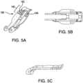
FIGS. 3-7 , and in accordance with the disclosed subject matter, the at least onearm flexure portion 150. The at least onearm deformable frame 160 comprising theflexure portion 150 and having first and seconddeformable portions deformable portions deformable frame 160. Furthermore, each of the first and seconddeformable portions contact portion 140 is at the undeformedcontact portion angle 144 and a deformed condition wherein thecontact portion 140 is at the flexedcontact portion angle 146. For purpose of illustration and not limitation, the undeformed condition is shown inFIGS. 3 and5 and the deformed condition is shown inFIG. 4 . Theflexure portion 150 can include at least oneslit 180 configured to enable thecontact portion 140 to move within the flex angle range as previously defined between the undeformedcontact portion angle 144 and the flexedcontact portion angle 146. As recognized by one of skill of the art, when the flexure portion is only included on the arm, the flex angle range can also be defined by the range of enabled flexion, when the arm is at a selected position, between thecontact portion axis 142 and thearm midsection axis 148, as illustrated inFIG. 4 . - In accordance with another aspect of the disclosed subject matter, the at least one
slit 180 can include at least one transverse cut in opposing lateral sides of the at least onearm slit 180 can include a plurality of transverse cuts extending from each opposing lateral side of the at least onearm slit 180 can be comprised of side cuts and/or top down cuts. Each of the at least oneslit 180 can be between about 0.25mm to about 1.27mm (about 0.01 inch to about 0.05 inch) wide. Further, the width of each of the at least oneslit 180 can be about 60 percent to about 200 percent the thickness of the arm. Each slit can provide about 5-15 degrees of flexion to the flex angle range, such the flex angle range can be about 5-15 degrees for a single slit, about 10-30 degrees for two slits, and about 15-45 degrees for 3 slits. - The at least one
arm central element 174 to an opposing second end, wherein thecontact portion 140 can be proximate the opposing second end, and theflexure portion 150 can be adjacent thecontact portion 140. Additionally, each of the at least oneslit 180 can be filled with a polymer having a durometer less than a durometer of the at least onearm slit 180 can further encourage cellular overgrowth on the at least onearm - Furthermore, the at least one
slit 180 can be formed of a kerf cut. A kerf cut can be a minimum width slit cut created by a given manufacturing method, for instance a laser spot size or a cutting blade width. A kerf cut can be one or more cuts in a material in a selected geometry that increases the flexibility of the material in a desired manner. The cuts can be made in a number of different geometries. For example, the cuts can be configured parallel to each other. Additionally or alternatively, the cuts can be configured perpendicular to each other, or at any other desired angle. The cuts can be straight or curved and can be uniform or non-uniform thicknesses. In this manner, the characteristics of the cuts be selected to obtain an overall desired flexibility in theflexure portion 150. - As shown in
FIG. 4 , theflexure portion 150 can be configured for portions of each deformable frame to contact each other during a maximum desired deformation. As such, self-contact between portions of theflexure portion 150 can limit the flexedcontact portion angle 146 and create a continuous radius of curvature throughout the flexure portion. Additionally, and as shown inFIG. 6 , the at least oneslit 180 can comprise aradiused cut 182 to distribute stresses more evenly within theflexure portion 150. - As further embodied herein in
FIG. 7A-B , the fixation device can be configured in an inverted position. InFIG. 7A , the at least oneslit 180 can include a cut having a wider angle on one side of the cut to enable tissue to more freely release from the cut. For example, a cut having a wide angle on an outer side of the cut can enable thefixation device 104 to retract through a valve in an inverted position with a smoother surface on a trailingside 186 of the cut. This can reduce the potential for tissue catching on the trailingside 186. In particular, and as shown in the expanded portion ofFIG. 7A for purpose of illustration and not limitation, a cut can havereference axis 184 extending perpendicularly from an apex of the cut. An inner side of the cut can have side wall with an angle X relative thereference axis 184. Likewise, an outer side of the cut can have a side wall with an angle Y relative thereference axis 184. As disclosed herein, angle X can be about 30 to 45 degrees and angle Y can be about 60 to about 80 degrees. - In
FIG. 7B , and in accordance with another aspect of the disclosed subject matter, the flexure portion can include anarm flexure portions 152 disposed on thearms leg flexure portions 154 disposed on thelegs FIG. 7B for purpose of illustration and not limitation, thefirst arm 108 can be under resistance from heart anatomy, such as from chordae catching and resting the end of thearm 108 during a withdrawal procedure. Theleg flexure portion 152 on thecorresponding leg 169, orarm flexure portion 154 on thecorresponding arm 108, or both (as shown inFIG. 7B ) can flex to narrow the overall profile of the fixation device and reduce resistance caused by the heart anatomy. As shown, and as a result of resistance on thefirst arm 108, theleg flexure portion 154 of thefirst leg 168 is flexed as compared to theleg flexure portion 154 of thesecond leg 169. As a result, thefirst arm 108 is flexed downward to a narrower configuration andsecond arm 110 is not flexed. Likewise, thearm flexure portion 152 of thefirst arm 108 is flexed as compared to thearm flexure portion 152 of thesecond arm 110. As a result, the end of thearm 108 is flexed inward to narrower configuration, and end of thearm 110 is not flexed. Moreover, it is understood that a device having only aleg flexure portion 152 or only anarm flexure portion 154 can likewise flex on their own to narrow the fixation device profile in the inverted position. Furthermore, it is contemplated that anyleg flexure portion 152 and anyarm flexure portion 154 in the disclosed subject matter herein can be incorporated in the fixation device shown inFIG. 7B and function in a substantially similar manner. - During manufacturing, the at least one
slit 180 can be formed from any number of different processes and techniques. For example, the at least oneslit 180 can be a 3D printed direct metal laser sintered (DMLS) part made from steel, cobalt chrome, titanium, nitinol, other alloys, or 3D printed plastics. Additionally or alternatively, the at least one slit can be metal stamped with cutaways, pierced, etched, laser cut, or electrical discharge machined. Cut depth and fillet radii may be adjusted using electro-chemical treatment such as electro-polishing. Each cut within the at least oneslit 180 can have a width that is at least one and a half times a thickness of the flexure portion. For example, the flexure portion thickness can be about 0.76mm (about 0.03 inch) and the cut width can be about 1.27mm (about 0.05 inch). Furthermore, theflexure portion 150 and portions of thearm 108 proximate theflexure portion 150 can have a varied material thickness. A varied material thickness can improve flexibility and stress distribution at both theflexure portion 150 and along portions of thearm 108 proximate theflexure portion 150. - Turing now to
FIGS. 8-14 , and in accordance with another aspect of the disclosed subject matter, the at least oneleg flexure portion 150. Theflexure portion 150 in the at least oneleg flexure portion 150 spring feature can be formed of any number of different configurations. For example, theflexure portion 150 can include a C-shapedcompression link 190 configured to enable the flex angle range be about 10 to about 20 degrees, as shown inFIGS. 9A and 9B . For further flexibility, theflexure portion 150 can include an S-shapedcompression link 192 configured to enable the flex angle range be about 20 to about 40 degrees, as shown inFIGS. 10A and 10B . Alternatively, theflexure portion 150 can include a Z-shapedcompression link 194 configured to enable the flex angle range be about 5 degrees to 15 degrees, as shown inFIGS. 11A and 11B . As a still further alternative, theflexure portion 150 can include a trapezoidal-shapedcompression link 196 configured to enable the flex angle range be about 5 to 15 degrees, as shown inFIGS. 12-13C . The trapezoidal-shapedcompression link 196 can have a width dimension that increases from a proximal location to a distal location, as shown at least inFIG. 13C . This trapezoidal design provides the benefit of improved stability and fatigue resistance and provides a stable closing state wherein the trapezoidal-shapedcompression link 196 can contact a central portion of the fixation device when thearm 108 is in a closed position. All embodiments shown inFIGS. 9A, 9B, 10A, 10B, 11A, 11B ,12 ,13A, 13B, and 13C may be configured with concave or convex curvature orientations. - Bends in the link members can be configured to touch each other to limit the maximum amount of compression, and thus, can limit the flex angle range. In accordance with another embodiment, and with reference to
FIGS. 14A and 14B , theflexure portion 150 can include at least onestop 198 configured to limit the flex angle range. For example, the at least one stop can limit the flex angle range to up to about 10 degrees. The at least onestop 198 can be included with any flexure portion design and is not limited to the compression link shown inFIG. 14 , which is for purpose of illustration and not limitation. As shown inFIG. 14 , twostops 198 can be used wherein thestops 198 are configured to contact each other during flexion to limit the flex angle range. Furthermore, and turning toFIG. 14B , thestops 198 can be oriented at differing angles to each other. For example, the stops can be oriented perpendicularly, as shown herein, wherein one stop is twisted 90 degrees relative to the other stop. Differing angle orientations between thestops 198 can increase their ability to make contact with each other and avoid sliding past each other. The at least one stop disclosed herein can be configured to limit the flex angle range before another mechanism would otherwise limit the flex angle range (e.g., from the stiffness of the flexure portion or link members that touch). - During manufacturing, the
leg links leg leg leg leg - Turing now to
FIG. 15 , and in accordance with another aspect of the disclosed subject matter, the at least onegripping element 116 includes amid-length portion 232 disposed along the at least onegripping element 116 and spaced from afree end 230 of the at least one gripping element. The at least onegripping element 116 further comprises anend portion 202 proximate thefree end 230, wherein theend portion 202 is biased towards the at least onearm 108 relative to themid-length portion 232. Theend portion 202 can enable the tip of thegripping element 116 to maintain a force towards a correspondingarm contact portion 140 during flexion of the contact portion. Theend portion 202 bias can be formed using similar manufacturing techniques as the techniques used to form other biases in thegripping element 116. A bend formed between theend portion 202 and themid-length portion 232 can create the bias. - With continued reference to
FIG. 15 , theflexure portion 150 can include anarm flexure portion 152 disposed on the at least onearm 108 configured to enable an arm source flexion range, and theflexure portion 150 further includes aleg flexure portion 154 disposed on the at least oneleg leg flexure portion 154, when flexed, creates global flex along an entire length of thearm 108. The arm flexure portion, when flexed, creates a localized flex at thecontact portion 140, rather than the entire length of thearm 108. - Turning now to
FIG. 16 , and in accordance with another aspect of the disclosed subject matter, agripping element 116 and anarm 108 are illustrated with anative leaflet 200 grasped therebetween. As depicted, for purpose of illustration and not limitation, arrows are shown to indicate a relative amount of force produced by the biased grippingelement 116 against the leaflet and thearm 108. As shown, the relative force decreases towards the free end of thegripping element 116. The force corresponds to the grasp force placed on anative leaflet 200, so, the greatest amount of grasp force on a native leaflet is spaced from thecontact portion 140. Accordingly, a fixation device can be configured to limit global flexure along an entire length of thearm 108 as compared to a flex at thecontact portion 140. Reduced flex along the length of the arm 108 (e.g., up to about 30 degrees) can ensure a secure leaflet grasp, while an increased flex at the contact portion (e.g., up to 45 degrees) can reduce strain on anative leaflet 200. - The embodiments illustrated herein are adapted for repair of a heart valve, such as a mitral valve, using an antegrade approach from a patient's left atrium. Prior to a procedure, imaging and various tests can be performed to anticipate and diagnose a patient's individual circumstances and assist a physician in selecting a fixation device having the desired parameters.
- While the embodiments disclosed herein utilize a push-to-open, pull-to-close mechanism for opening and closing arms it should be understood that other suitable mechanisms can be used, such as a pull-to-open, push-to-close mechanism. Likewise, other actuation elements can be used for deployment of the gripping elements.
- The components disclosed herein, such as the arm and leg components, can be formed with an alternative geometry by manufacturing from tubing. For example, tube cutting manufacturing techniques can be used wherein each component would have a "C" shaped cross section(e.g., a "half pipe") cut from a tube to create a trough for the arm and a profile for the leg.
- While the disclosed subject matter is described herein in terms of certain preferred embodiments for purpose of illustration and not limitation, those skilled in the art will recognize that various modifications and improvements can be made to the disclosed subject matter without departing from the scope thereof. Moreover, although individual features of one embodiment of the disclosed subject matter can be discussed herein or shown in the drawings of one embodiment and not in other embodiments, it should be readily apparent that individual features of one embodiment can be combined with one or more features of another embodiment or features from a plurality of embodiments.
- In addition to the specific embodiments claimed below, the disclosed subject matter is also directed to other embodiments having any other possible combination of the dependent features claimed below and those disclosed above. As such, the particular features presented in the dependent claims and disclosed above can be combined with each other in other possible combinations. Thus, the foregoing description of specific embodiments of the disclosed subject matter has been presented for purposes of illustration and description. It is not intended to be exhaustive or to limit the disclosed subject matter to those embodiments disclosed.
- It will be apparent to those skilled in the art that various modifications and variations can be made in the method and system of the disclosed subject matter without departing from the scope of the disclosed subject matter. Thus, it is intended that the disclosed subject matter include modifications and variations that are within the scope of the appended claims. The invention is defined by the appended claims.
Claims (11)
- A fixation device (104) for fixation of leaflets of a heart valve comprising:a central element (174) defining a central axis (156);a distal portion (106) comprising:at least one arm (108, 110) coupled to the central element, the at least one arm moveable to a selected position between a fully open position and a fully closed position, andat least one leg (168, 169) operatively coupled to the at least one arm and configured to move the at least one arm to the selected position between the fully open position and the fully closed position,wherein the at least one arm includes a contact portion (140) configured to engage native heart valve tissue, the contact portion defining a contact portion axis (142),wherein the distal portion includes a flexure portion (150) configured to enable the contact portion in the selected position to move within a flex angle range between an undeformed contact portion angle relative to the central axis and a flexed contact portion angle relative to the central axis, wherein the flexed contact portion angle is greater than the undeformed contact portion angle, the flex angle range being about 10 degrees to about 45 degrees,wherein the at least one arm comprises the flexure portion,wherein the at least one arm extends from a first end proximate the central element to an opposing second end, wherein the contact portion is proximate the opposing second end, the contact portion is defined only along an outer half of the length of the arm, and the flexure portion is adjacent the contact portion; andat least one gripping element (116, 118) moveable relative to the at least one arm to capture a native leaflet therebetween.
- The fixation device of claim 1, wherein the at least one arm comprises a deformable frame (160) comprising the flexure portion and having first and second deformable portions (162, 164), each of the first and second deformable portions disposed along a respective lateral side of the deformable frame, and, optionally,
wherein each of the first and second deformable portions have an undeformed condition wherein the contact portion is at the undeformed contact portion angle and a deformed condition wherein the contact portion is at the flexed contact portion angle. - The fixation device of claim 2, wherein the flexure portion includes at least one slit (180) configured to enable the contact portion to move between the undeformed contact portion angle and the flexed contact portion angle.
- The fixation device of claim 3, wherein the at least one slit comprises one or more of;(i) at least one transverse cut in opposing lateral sides of the at least one arm; and(ii) a plurality of transverse cuts extending from each opposing lateral side of the at least one arm.
- The fixation device of claim 3, wherein each of the at least one slit is one or more of:(i) between about 0.25mm to about 0.76mm (about 0.01 inch to about 0.03 inch wide;(ii) filled with a polymer having a durometer less than a durometer of the at least one arm; and(iii) formed of a kerf cut.
- The fixation device of any of claims 1 to 5, wherein the at least one gripping element comprises a mid-length portion (232) disposed along the at least one gripping element and spaced from a free end (230) of the at least one gripping element, and the at least one gripping element further comprises an end portion (202) proximate the free end, wherein the end portion is biased towards the at least one arm relative to the mid-length portion.
- The fixation device of claim 1, wherein the flexure portion includes an arm flexure portion (152) disposed on the at least one arm configured to enable an arm source flexion angle range, and the flexure portion further includes a leg flexure portion (154) disposed on the at least one leg configured to enable a leg source flexion angle range, wherein the arm source flexion angle range and leg source flexion range combine to enable the flex angle range.
- The fixation device of claim 7, wherein the combined arm source flex angle range and leg source flex angle range is about 45 degrees or less.
- The fixation device of any of claims 1 to 8, wherein the central element comprises a base portion (170) coupled to the at least one leg, wherein distal movement of the base portion moves the at least one leg to move the at least one arm towards the fully open position.
- The fixation device of claim 9, wherein the fixation device is configured to prevent distal movement of the base portion when the at least one arm is in the selected position.
- The fixation device of claim 10, wherein the fixation device further comprises a locking mechanism (178) configured to prevent distal movement of the base portion.
Applications Claiming Priority (1)
| Application Number | Priority Date | Filing Date | Title |
|---|---|---|---|
| US202163182167P | 2021-04-30 | 2021-04-30 |
Publications (2)
| Publication Number | Publication Date |
|---|---|
| EP4082481A1 EP4082481A1 (en) | 2022-11-02 |
| EP4082481B1true EP4082481B1 (en) | 2024-04-17 |
Family
ID=81448894
Family Applications (1)
| Application Number | Title | Priority Date | Filing Date |
|---|---|---|---|
| EP22170956.1AActiveEP4082481B1 (en) | 2021-04-30 | 2022-04-29 | Fixation device having a flexure portion |
Country Status (2)
| Country | Link |
|---|---|
| US (2) | US12138169B2 (en) |
| EP (1) | EP4082481B1 (en) |
Families Citing this family (2)
| Publication number | Priority date | Publication date | Assignee | Title |
|---|---|---|---|---|
| EP3648678A4 (en) | 2017-07-06 | 2021-03-24 | Raghuveer Basude | TISSUE GRIPPING DEVICES AND RELATED PROCEDURES |
| CN119700378A (en) | 2018-04-24 | 2025-03-28 | 拉古维尔·巴苏德 | Retrievable tissue grasping device, spacer, artificial valve and related methods |
Family Cites Families (193)
| Publication number | Priority date | Publication date | Assignee | Title |
|---|---|---|---|---|
| US3378010A (en) | 1965-07-28 | 1968-04-16 | Coldling | Surgical clip with means for releasing the clamping pressure |
| US3874388A (en) | 1973-02-12 | 1975-04-01 | Ochsner Med Found Alton | Shunt defect closure system |
| FR2306671A1 (en) | 1975-04-11 | 1976-11-05 | Rhone Poulenc Ind | VALVULAR IMPLANT |
| US4340091A (en) | 1975-05-07 | 1982-07-20 | Albany International Corp. | Elastomeric sheet materials for heart valve and other prosthetic implants |
| US4007743A (en) | 1975-10-20 | 1977-02-15 | American Hospital Supply Corporation | Opening mechanism for umbrella-like intravascular shunt defect closure device |
| US4327736A (en) | 1979-11-20 | 1982-05-04 | Kanji Inoue | Balloon catheter |
| US4657024A (en) | 1980-02-04 | 1987-04-14 | Teleflex Incorporated | Medical-surgical catheter |
| US4809695A (en) | 1981-10-21 | 1989-03-07 | Owen M. Gwathmey | Suturing assembly and method |
| US4693248A (en) | 1983-06-20 | 1987-09-15 | Ethicon, Inc. | Two-piece tissue fastener with deformable retaining receiver |
| US4716886A (en) | 1986-05-01 | 1988-01-05 | Norman Schulman | Umbilical cord clamp and cutters |
| US5125895A (en) | 1986-07-22 | 1992-06-30 | Medtronic Versaflex, Inc. | Steerable catheter |
| US5478353A (en) | 1987-05-14 | 1995-12-26 | Yoon; Inbae | Suture tie device system and method for suturing anatomical tissue proximate an opening |
| US5542949A (en) | 1987-05-14 | 1996-08-06 | Yoon; Inbae | Multifunctional clip applier instrument |
| US4795458A (en) | 1987-07-02 | 1989-01-03 | Regan Barrie F | Stent for use following balloon angioplasty |
| US5002562A (en) | 1988-06-03 | 1991-03-26 | Oberlander Michael A | Surgical clip |
| US5069679A (en) | 1989-02-16 | 1991-12-03 | Taheri Syde A | Method and apparatus for removing venous valves |
| US4930674A (en) | 1989-02-24 | 1990-06-05 | Abiomed, Inc. | Surgical stapler |
| US5092872A (en) | 1989-07-28 | 1992-03-03 | Jacob Segalowitz | Valvulotome catheter |
| ATE107150T1 (en) | 1990-04-02 | 1994-07-15 | Kanji Inoue | DEVICE FOR CLOSING A SHUTTLE OPENING BY A NON-OPERATIONAL METHOD. |
| US5098440A (en) | 1990-08-14 | 1992-03-24 | Cordis Corporation | Object retrieval method and apparatus |
| US5389102A (en) | 1990-09-13 | 1995-02-14 | United States Surgical Corporation | Apparatus and method for subcuticular stapling of body tissue |
| US5611794A (en) | 1990-10-11 | 1997-03-18 | Lasersurge, Inc. | Clamp for approximating tissue sections |
| US5222963A (en) | 1991-01-17 | 1993-06-29 | Ethicon, Inc. | Pull-through circular anastomosic intraluminal stapler with absorbable fastener means |
| US5163955A (en) | 1991-01-24 | 1992-11-17 | Autogenics | Rapid assembly, concentric mating stent, tissue heart valve with enhanced clamping and tissue alignment |
| US5330501A (en) | 1991-05-30 | 1994-07-19 | United States Surgical Corporation | Tissue gripping device for use with a cannula and a cannula incorporating the device |
| US5147370A (en) | 1991-06-12 | 1992-09-15 | Mcnamara Thomas O | Nitinol stent for hollow body conduits |
| GR920100358A (en) | 1991-08-23 | 1993-06-07 | Ethicon Inc | Surgical anastomosis stapling instrument. |
| EP0541063B1 (en) | 1991-11-05 | 1998-09-02 | The Children's Medical Center Corporation | Improved occluder for repair of cardiac and vascular defects |
| US5363861A (en) | 1991-11-08 | 1994-11-15 | Ep Technologies, Inc. | Electrode tip assembly with variable resistance to bending |
| CA2128338C (en) | 1992-01-21 | 2004-10-12 | Gladwin S. Das | Septal defect closure device |
| US5327905A (en) | 1992-02-14 | 1994-07-12 | Boaz Avitall | Biplanar deflectable catheter for arrhythmogenic tissue ablation |
| US5782239A (en) | 1992-06-30 | 1998-07-21 | Cordis Webster, Inc. | Unique electrode configurations for cardiovascular electrode catheter with built-in deflection method and central puller wire |
| US6048351A (en) | 1992-09-04 | 2000-04-11 | Scimed Life Systems, Inc. | Transvaginal suturing system |
| US5342373A (en) | 1992-09-14 | 1994-08-30 | Ethicon, Inc. | Sterile clips and instrument for their placement |
| US5601224A (en) | 1992-10-09 | 1997-02-11 | Ethicon, Inc. | Surgical instrument |
| US5814097A (en) | 1992-12-03 | 1998-09-29 | Heartport, Inc. | Devices and methods for intracardiac procedures |
| US5403326A (en) | 1993-02-01 | 1995-04-04 | The Regents Of The University Of California | Method for performing a gastric wrap of the esophagus for use in the treatment of esophageal reflux |
| US5797960A (en) | 1993-02-22 | 1998-08-25 | Stevens; John H. | Method and apparatus for thoracoscopic intracardiac procedures |
| US6346074B1 (en) | 1993-02-22 | 2002-02-12 | Heartport, Inc. | Devices for less invasive intracardiac interventions |
| JPH08502438A (en) | 1993-02-22 | 1996-03-19 | ヴァリーラブ・インコーポレーテッド | Laparoscopic distraction tension retractor device and method |
| US5389077A (en) | 1993-03-03 | 1995-02-14 | Uresil Corporation | Minimally invasive body cavity penetrating instruments |
| US5636634A (en) | 1993-03-16 | 1997-06-10 | Ep Technologies, Inc. | Systems using guide sheaths for introducing, deploying, and stabilizing cardiac mapping and ablation probes |
| NL9300572A (en) | 1993-03-31 | 1994-10-17 | Cordis Europ | Method for manufacturing an extrusion profile with length-varying properties and catheter manufactured therewith. |
| US5456400A (en) | 1993-04-22 | 1995-10-10 | United States Surgical Corporation | Apparatus and clip for fastening body tissue |
| FR2708458B1 (en) | 1993-08-03 | 1995-09-15 | Seguin Jacques | Prosthetic ring for cardiac surgery. |
| US5450860A (en) | 1993-08-31 | 1995-09-19 | W. L. Gore & Associates, Inc. | Device for tissue repair and method for employing same |
| US5607462A (en) | 1993-09-24 | 1997-03-04 | Cardiac Pathways Corporation | Catheter assembly, catheter and multi-catheter introducer for use therewith |
| US5452837A (en) | 1994-01-21 | 1995-09-26 | Ethicon Endo-Surgery, Inc. | Surgical stapler with tissue gripping ridge |
| US5609598A (en) | 1994-12-30 | 1997-03-11 | Vnus Medical Technologies, Inc. | Method and apparatus for minimally invasive treatment of chronic venous insufficiency |
| US5976159A (en) | 1995-02-24 | 1999-11-02 | Heartport, Inc. | Surgical clips and methods for tissue approximation |
| US5695504A (en) | 1995-02-24 | 1997-12-09 | Heartport, Inc. | Devices and methods for performing a vascular anastomosis |
| US5695505A (en) | 1995-03-09 | 1997-12-09 | Yoon; Inbae | Multifunctional spring clips and cartridges and applicators therefor |
| US5562678A (en) | 1995-06-02 | 1996-10-08 | Cook Pacemaker Corporation | Needle's eye snare |
| US5716417A (en) | 1995-06-07 | 1998-02-10 | St. Jude Medical, Inc. | Integral supporting structure for bioprosthetic heart valve |
| US6117144A (en) | 1995-08-24 | 2000-09-12 | Sutura, Inc. | Suturing device and method for sealing an opening in a blood vessel or other biological structure |
| US6015417A (en) | 1996-01-25 | 2000-01-18 | Reynolds, Jr.; Walker | Surgical fastener |
| US5860992A (en) | 1996-01-31 | 1999-01-19 | Heartport, Inc. | Endoscopic suturing devices and methods |
| US6182664B1 (en) | 1996-02-19 | 2001-02-06 | Edwards Lifesciences Corporation | Minimally invasive cardiac valve surgery procedure |
| US5843178A (en) | 1996-06-20 | 1998-12-01 | St. Jude Medical, Inc. | Suture guard for annuloplasty ring |
| US5855601A (en) | 1996-06-21 | 1999-01-05 | The Trustees Of Columbia University In The City Of New York | Artificial heart valve and method and device for implanting the same |
| WO1998007375A1 (en) | 1996-08-22 | 1998-02-26 | The Trustees Of Columbia University | Endovascular flexible stapling device |
| US5741297A (en) | 1996-08-28 | 1998-04-21 | Simon; Morris | Daisy occluder and method for septal defect repair |
| US5713911A (en) | 1996-10-03 | 1998-02-03 | United States Surgical Corporation | Surgical clip |
| US5755778A (en) | 1996-10-16 | 1998-05-26 | Nitinol Medical Technologies, Inc. | Anastomosis device |
| US6332880B1 (en) | 1996-12-19 | 2001-12-25 | Ep Technologies, Inc. | Loop structures for supporting multiple electrode elements |
| EP0850607A1 (en) | 1996-12-31 | 1998-07-01 | Cordis Corporation | Valve prosthesis for implantation in body channels |
| US6149658A (en) | 1997-01-09 | 2000-11-21 | Coalescent Surgical, Inc. | Sutured staple surgical fasteners, instruments and methods for minimally invasive vascular and endoscopic surgery |
| EP2133030A1 (en) | 1997-06-27 | 2009-12-16 | The Trustees of Columbia University of the City of New York | Method and apparatus for circulatory valve repair |
| IL121316A (en) | 1997-07-15 | 2001-07-24 | Litana Ltd | Implantable medical device of shape memory alloy |
| WO1999007354A2 (en) | 1997-08-08 | 1999-02-18 | Duke University | Compositions, apparatus and methods for facilitating surgical procedures |
| FR2768324B1 (en) | 1997-09-12 | 1999-12-10 | Jacques Seguin | SURGICAL INSTRUMENT FOR PERCUTANEOUSLY FIXING TWO AREAS OF SOFT TISSUE, NORMALLY MUTUALLY REMOTE, TO ONE ANOTHER |
| FR2768325B1 (en) | 1997-09-16 | 1999-11-19 | Instr Medecine Veterinaire | CATHETER FOR ARTIFICIAL INSEMINATION OF BIRDS, ESPECIALLY TURKEYS, AND METHOD FOR PRODUCING SUCH A CATHETER |
| AU9669898A (en) | 1997-09-26 | 1999-04-12 | Cardeon Corporation | Multi-function aortic catheterization and bumper instrument |
| US6120496A (en) | 1998-05-05 | 2000-09-19 | Scimed Life Systems, Inc. | Surgical method and apparatus for positioning a diagnostic or therapeutic element within the body and coupling device for use with same |
| US6200315B1 (en) | 1997-12-18 | 2001-03-13 | Medtronic, Inc. | Left atrium ablation catheter |
| US6193734B1 (en) | 1998-01-23 | 2001-02-27 | Heartport, Inc. | System for performing vascular anastomoses |
| US6599311B1 (en) | 1998-06-05 | 2003-07-29 | Broncus Technologies, Inc. | Method and assembly for lung volume reduction |
| US7569062B1 (en) | 1998-07-15 | 2009-08-04 | St. Jude Medical, Inc. | Mitral and tricuspid valve repair |
| US6165183A (en) | 1998-07-15 | 2000-12-26 | St. Jude Medical, Inc. | Mitral and tricuspid valve repair |
| US6544215B1 (en) | 1998-10-02 | 2003-04-08 | Scimed Life Systems, Inc. | Steerable device for introducing diagnostic and therapeutic apparatus into the body |
| US7972323B1 (en) | 1998-10-02 | 2011-07-05 | Boston Scientific Scimed, Inc. | Steerable device for introducing diagnostic and therapeutic apparatus into the body |
| US6217528B1 (en) | 1999-02-11 | 2001-04-17 | Scimed Life Systems, Inc. | Loop structure having improved tissue contact capability |
| US8118822B2 (en) | 1999-03-01 | 2012-02-21 | Medtronic, Inc. | Bridge clip tissue connector apparatus and methods |
| US6064600A (en) | 1999-03-01 | 2000-05-16 | Micron Technology, Inc. | Methods and apparatus for reading memory device register data |
| US7226467B2 (en) | 1999-04-09 | 2007-06-05 | Evalve, Inc. | Fixation device delivery catheter, systems and methods of use |
| US6752813B2 (en) | 1999-04-09 | 2004-06-22 | Evalve, Inc. | Methods and devices for capturing and fixing leaflets in valve repair |
| AU770243B2 (en) | 1999-04-09 | 2004-02-19 | Evalve, Inc. | Methods and apparatus for cardiac valve repair |
| US7811296B2 (en) | 1999-04-09 | 2010-10-12 | Evalve, Inc. | Fixation devices for variation in engagement of tissue |
| US20040044350A1 (en) | 1999-04-09 | 2004-03-04 | Evalve, Inc. | Steerable access sheath and methods of use |
| US10327743B2 (en) | 1999-04-09 | 2019-06-25 | Evalve, Inc. | Device and methods for endoscopic annuloplasty |
| US8216256B2 (en) | 1999-04-09 | 2012-07-10 | Evalve, Inc. | Detachment mechanism for implantable fixation devices |
| AU5884400A (en) | 1999-06-25 | 2001-01-31 | Vahid Saadat | Apparatus and methods for treating tissue |
| US6231561B1 (en) | 1999-09-20 | 2001-05-15 | Appriva Medical, Inc. | Method and apparatus for closing a body lumen |
| US6312447B1 (en) | 1999-10-13 | 2001-11-06 | The General Hospital Corporation | Devices and methods for percutaneous mitral valve repair |
| US6626930B1 (en) | 1999-10-21 | 2003-09-30 | Edwards Lifesciences Corporation | Minimally invasive mitral valve repair method and apparatus |
| US6551303B1 (en) | 1999-10-27 | 2003-04-22 | Atritech, Inc. | Barrier device for ostium of left atrial appendage |
| US6926730B1 (en) | 2000-10-10 | 2005-08-09 | Medtronic, Inc. | Minimally invasive valve repair procedure and apparatus |
| US6797002B2 (en) | 2000-02-02 | 2004-09-28 | Paul A. Spence | Heart valve repair apparatus and methods |
| US6419696B1 (en) | 2000-07-06 | 2002-07-16 | Paul A. Spence | Annuloplasty devices and related heart valve repair methods |
| SE0002878D0 (en) | 2000-08-11 | 2000-08-11 | Kimblad Ola | Device and method of treatment of atrioventricular regurgitation |
| US20020107531A1 (en) | 2001-02-06 | 2002-08-08 | Schreck Stefan G. | Method and system for tissue repair using dual catheters |
| WO2002078576A2 (en) | 2001-03-29 | 2002-10-10 | Viacor, Inc. | Method and apparatus for improving mitral valve function |
| US6837867B2 (en) | 2001-04-30 | 2005-01-04 | Biosense Webster, Inc. | Steerable catheter with reinforced tip |
| US7338514B2 (en) | 2001-06-01 | 2008-03-04 | St. Jude Medical, Cardiology Division, Inc. | Closure devices, related delivery methods and tools, and related methods of use |
| EP1432369B1 (en) | 2001-08-31 | 2008-02-27 | Mitral Interventions | Apparatus for valve repair |
| US6575971B2 (en) | 2001-11-15 | 2003-06-10 | Quantum Cor, Inc. | Cardiac valve leaflet stapler device and methods thereof |
| US6978176B2 (en) | 2001-12-08 | 2005-12-20 | Lattouf Omar M | Treatment for patient with congestive heart failure |
| US7048754B2 (en) | 2002-03-01 | 2006-05-23 | Evalve, Inc. | Suture fasteners and methods of use |
| US6855137B2 (en) | 2002-03-07 | 2005-02-15 | Visionary Biomedical, Inc. | Catheter shaft with coextruded stiffener |
| US7101395B2 (en) | 2002-06-12 | 2006-09-05 | Mitral Interventions, Inc. | Method and apparatus for tissue connection |
| US20040034365A1 (en) | 2002-08-16 | 2004-02-19 | Lentz David J. | Catheter having articulation system |
| JP4774048B2 (en)* | 2004-05-14 | 2011-09-14 | エヴァルヴ インコーポレイテッド | Locking mechanism of fixing device engaged with tissue and tissue engaging method |
| US7556632B2 (en) | 2004-07-09 | 2009-07-07 | Reza Zadno | Device and method for repairing tissue |
| WO2006037073A2 (en) | 2004-09-27 | 2006-04-06 | Evalve, Inc. | Methods and devices for tissue grasping and assessment |
| CA2597066C (en) | 2005-02-07 | 2014-04-15 | Evalve, Inc. | Methods, systems and devices for cardiac valve repair |
| US10076327B2 (en) | 2010-09-14 | 2018-09-18 | Evalve, Inc. | Flexible actuator mandrel for tissue apposition systems |
| US8945177B2 (en) | 2011-09-13 | 2015-02-03 | Abbott Cardiovascular Systems Inc. | Gripper pusher mechanism for tissue apposition systems |
| US9011468B2 (en) | 2011-09-13 | 2015-04-21 | Abbott Cardiovascular Systems Inc. | Independent gripper |
| US10624664B2 (en) | 2011-09-28 | 2020-04-21 | Evalve, Inc. | Apparatuses and methods for cutting a tissue bridge and/or removing a heart valve clip or suture |
| US20150112210A1 (en) | 2013-10-17 | 2015-04-23 | Abbott Cardiovascular Systems Inc. | Lumen based pressure measurement guide wire system for measuring pressure in a body lumen |
| US10390943B2 (en) | 2014-03-17 | 2019-08-27 | Evalve, Inc. | Double orifice device for transcatheter mitral valve replacement |
| US9572666B2 (en) | 2014-03-17 | 2017-02-21 | Evalve, Inc. | Mitral valve fixation device removal devices and methods |
| CN105455930B (en)* | 2014-06-11 | 2019-08-16 | 先健科技(深圳)有限公司 | Lung volume reduction elasticity implant and instrument |
| WO2016090308A1 (en) | 2014-12-04 | 2016-06-09 | Edwards Lifesciences Corporation | Percutaneous clip for repairing a heart valve |
| US9901352B2 (en) | 2014-12-12 | 2018-02-27 | Atricure, Inc. | Occlusion clip |
| US10188392B2 (en) | 2014-12-19 | 2019-01-29 | Abbott Cardiovascular Systems, Inc. | Grasping for tissue repair |
| US10524912B2 (en) | 2015-04-02 | 2020-01-07 | Abbott Cardiovascular Systems, Inc. | Tissue fixation devices and methods |
| US9827122B2 (en) | 2015-05-04 | 2017-11-28 | Abbott Cardiovascular Systems Inc. | System for a catheter |
| EP3294219B1 (en) | 2015-05-14 | 2020-05-13 | Edwards Lifesciences Corporation | Heart valve sealing devices and delivery devices therefor |
| US10376673B2 (en) | 2015-06-19 | 2019-08-13 | Evalve, Inc. | Catheter guiding system and methods |
| US10238494B2 (en) | 2015-06-29 | 2019-03-26 | Evalve, Inc. | Self-aligning radiopaque ring |
| US10667815B2 (en) | 2015-07-21 | 2020-06-02 | Evalve, Inc. | Tissue grasping devices and related methods |
| US10413408B2 (en) | 2015-08-06 | 2019-09-17 | Evalve, Inc. | Delivery catheter systems, methods, and devices |
| USD809139S1 (en) | 2015-10-09 | 2018-01-30 | Evalve, Inc. | Handle for a medical device |
| US10238495B2 (en) | 2015-10-09 | 2019-03-26 | Evalve, Inc. | Delivery catheter handle and methods of use |
| US10226309B2 (en) | 2015-10-09 | 2019-03-12 | Evalve, Inc. | Devices, systems, and methods to support, stabilize, and position a medical device |
| USD816832S1 (en) | 2015-10-09 | 2018-05-01 | Evalve, Inc. | Stabilizer |
| US10299924B2 (en) | 2016-02-10 | 2019-05-28 | Abbott Cardiovascular Systems Inc. | System and method for implant delivery |
| US10398549B2 (en) | 2016-03-15 | 2019-09-03 | Abbott Cardiovascular Systems Inc. | System and method for transcatheter heart valve platform |
| EP3868306A1 (en) | 2016-06-20 | 2021-08-25 | Evalve, Inc. | Transapical removal device |
| US10736632B2 (en) | 2016-07-06 | 2020-08-11 | Evalve, Inc. | Methods and devices for valve clip excision |
| US10478304B2 (en) | 2016-07-20 | 2019-11-19 | Abbott Cardiovascular Systems Inc. | Independent system for tricuspid valve repair |
| US10058426B2 (en) | 2016-07-20 | 2018-08-28 | Abbott Cardiovascular Systems Inc. | System for tricuspid valve repair |
| WO2018022919A1 (en) | 2016-07-28 | 2018-02-01 | Evalve, Inc. | Systems and methods for intra-procedural cardiac pressure monitoring |
| US10945842B2 (en) | 2016-08-04 | 2021-03-16 | Evalve, Inc. | Annular augmentation device for cardiac valve repair |
| US11071564B2 (en) | 2016-10-05 | 2021-07-27 | Evalve, Inc. | Cardiac valve cutting device |
| US10363138B2 (en) | 2016-11-09 | 2019-07-30 | Evalve, Inc. | Devices for adjusting the curvature of cardiac valve structures |
| US10398553B2 (en) | 2016-11-11 | 2019-09-03 | Evalve, Inc. | Opposing disk device for grasping cardiac valve tissue |
| US10398552B2 (en) | 2016-11-15 | 2019-09-03 | Abbott Cardiovascular Systems Inc. | Fixation devices, systems and methods for heart valve leaf repair |
| US10426616B2 (en) | 2016-11-17 | 2019-10-01 | Evalve, Inc. | Cardiac implant delivery system |
| US10420565B2 (en) | 2016-11-29 | 2019-09-24 | Abbott Cardiovascular Systems Inc. | Cinch and post for tricuspid valve repair |
| US10548614B2 (en) | 2016-11-29 | 2020-02-04 | Evalve, Inc. | Tricuspid valve repair system |
| US10779837B2 (en) | 2016-12-08 | 2020-09-22 | Evalve, Inc. | Adjustable arm device for grasping tissues |
| US10314586B2 (en) | 2016-12-13 | 2019-06-11 | Evalve, Inc. | Rotatable device and method for fixing tricuspid valve tissue |
| US10675439B2 (en) | 2017-02-21 | 2020-06-09 | Abbott Cardiovascular Systems Inc. | High torsion delivery catheter element |
| US10952852B2 (en) | 2017-02-24 | 2021-03-23 | Abbott Cardiovascular Systems Inc. | Double basket assembly for valve repair |
| US10149685B2 (en) | 2017-02-28 | 2018-12-11 | Abbott Cardiovascular Systems Inc. | System and method for mitral valve function |
| US11224511B2 (en) | 2017-04-18 | 2022-01-18 | Edwards Lifesciences Corporation | Heart valve sealing devices and delivery devices therefor |
| US10959846B2 (en) | 2017-05-10 | 2021-03-30 | Edwards Lifesciences Corporation | Mitral valve spacer device |
| WO2018209313A1 (en) | 2017-05-12 | 2018-11-15 | Evalve, Inc. | Long arm valve repair clip |
| US10779829B2 (en) | 2017-06-07 | 2020-09-22 | Evalve, Inc. | Tissue compression device for cardiac valve repair |
| US10517598B2 (en) | 2017-06-07 | 2019-12-31 | Evalve, Inc. | Tissue tensioning device for cardiac valve repair |
| US20190030285A1 (en) | 2017-07-27 | 2019-01-31 | Evalve, Inc. | Intravascular delivery system with centralized steering |
| US20190083242A1 (en)* | 2017-09-19 | 2019-03-21 | Cardiovalve Ltd. | Systems and methods for implanting a prosthetic valve within a native heart valve |
| US10646343B2 (en) | 2017-10-27 | 2020-05-12 | Abbott Cardiovascular Systems Inc. | System and method for valve activation |
| US12318288B2 (en) | 2017-10-30 | 2025-06-03 | Cephea Valve Technologies, Inc. | Insert for distal end cap |
| CN207368927U (en) | 2017-10-31 | 2018-05-15 | 福世达(厦门)太阳能科技有限公司 | Crocodile clip |
| US10856985B2 (en) | 2017-11-21 | 2020-12-08 | Abbott Cardiovascular Systems Inc. | System and method for annuloplasty |
| WO2019129024A1 (en) | 2017-12-27 | 2019-07-04 | 上海锦葵医疗器械股份有限公司 | Valve clip |
| US10231837B1 (en) | 2018-01-09 | 2019-03-19 | Edwards Lifesciences Corporation | Native valve repair devices and procedures |
| US10105222B1 (en)* | 2018-01-09 | 2018-10-23 | Edwards Lifesciences Corporation | Native valve repair devices and procedures |
| US10507109B2 (en) | 2018-01-09 | 2019-12-17 | Edwards Lifesciences Corporation | Native valve repair devices and procedures |
| US10245144B1 (en) | 2018-01-09 | 2019-04-02 | Edwards Lifesciences Corporation | Native valve repair devices and procedures |
| US10130475B1 (en) | 2018-01-09 | 2018-11-20 | Edwards Lifesciences Corporation | Native valve repair devices and procedures |
| US10076415B1 (en) | 2018-01-09 | 2018-09-18 | Edwards Lifesciences Corporation | Native valve repair devices and procedures |
| US10238493B1 (en) | 2018-01-09 | 2019-03-26 | Edwards Lifesciences Corporation | Native valve repair devices and procedures |
| US10136993B1 (en) | 2018-01-09 | 2018-11-27 | Edwards Lifesciences Corporation | Native valve repair devices and procedures |
| US10159570B1 (en) | 2018-01-09 | 2018-12-25 | Edwards Lifesciences Corporation | Native valve repair devices and procedures |
| US10973639B2 (en) | 2018-01-09 | 2021-04-13 | Edwards Lifesciences Corporation | Native valve repair devices and procedures |
| US10111751B1 (en) | 2018-01-09 | 2018-10-30 | Edwards Lifesciences Corporation | Native valve repair devices and procedures |
| US10123873B1 (en) | 2018-01-09 | 2018-11-13 | Edwards Lifesciences Corporation | Native valve repair devices and procedures |
| US10945844B2 (en) | 2018-10-10 | 2021-03-16 | Edwards Lifesciences Corporation | Heart valve sealing devices and delivery devices therefor |
| US12102531B2 (en) | 2018-10-22 | 2024-10-01 | Evalve, Inc. | Tissue cutting systems, devices and methods |
| EP3941361B1 (en) | 2019-05-22 | 2025-09-10 | Evalve, Inc. | Devices and systems for accessing and repairing a heart valve |
| JP7566004B2 (en) | 2019-07-15 | 2024-10-11 | エバルブ,インコーポレイティド | Wide clip with non-deforming wings |
| CA3147410A1 (en) | 2019-07-15 | 2021-01-21 | Evalve, Inc. | Proximal element actuator fixation and release mechanisms |
| JP7543391B2 (en) | 2019-07-15 | 2024-09-02 | エバルブ,インコーポレイティド | Method of Actuating Individual Proximal Elements |
| EP4014894A4 (en)* | 2019-08-13 | 2022-08-31 | Hangzhou Valgen Medtech Co., Ltd. | Adjustable valve clamping device and valve clamping system |
| US11464636B2 (en) | 2019-10-11 | 2022-10-11 | Evalve, Inc. | Repair clip for variable tissue thickness |
| US12109115B2 (en) | 2019-12-18 | 2024-10-08 | Evalve, Inc. | Wide clip with deformable width |
| CN115300181B (en) | 2021-05-06 | 2025-08-12 | 杭州德晋医疗科技有限公司 | Tricuspid valve repair device and system with stable clamping force |
| CN114176837B (en) | 2021-12-09 | 2025-07-22 | 北京领健医疗科技有限公司 | Valve clamp and valve repair system |
| CN216221859U (en) | 2021-12-22 | 2022-04-08 | 科瑞迈吉(北京)医疗科技有限公司 | Mitral valve forceps holder and mitral valve forceps holder conveying device |
- 2022
- 2022-04-29EPEP22170956.1Apatent/EP4082481B1/enactiveActive
- 2022-04-29USUS17/732,830patent/US12138169B2/enactiveActive
- 2024
- 2024-10-09USUS18/910,203patent/US20250025303A1/enactivePending
Also Published As
| Publication number | Publication date |
|---|---|
| EP4082481A1 (en) | 2022-11-02 |
| US12138169B2 (en) | 2024-11-12 |
| US20220346954A1 (en) | 2022-11-03 |
| US20250025303A1 (en) | 2025-01-23 |
Similar Documents
| Publication | Publication Date | Title |
|---|---|---|
| US20250000654A1 (en) | Wide Clip With Deformable Width | |
| US12295846B2 (en) | Long arm valve repair clip | |
| US20240277475A1 (en) | Repair Clip For Variable Tissue Thickness | |
| US12178704B2 (en) | Wide clip with nondeformable wings | |
| EP3302366B1 (en) | Cardiac valve repair devices configured for percutaneous delivery | |
| US20250025303A1 (en) | Fixation Device Having A Flexure Portion | |
| JP2023531335A (en) | Systems and methods for heart valve leaflet repair | |
| JP2009519783A (en) | Papillary muscle position control device, system and method | |
| US11491008B2 (en) | Annuloplasty device | |
| CN119053301A (en) | Heart valve repair device and delivery device therefor | |
| US20240164896A1 (en) | Tunable Fixation Device | |
| WO2024108118A1 (en) | Fixation device with symmetrical extension elements | |
| CN218979341U (en) | Prosthetic heart valve device and implantation system | |
| WO2024108146A1 (en) | Size adapter attachments |
Legal Events
| Date | Code | Title | Description |
|---|---|---|---|
| PUAI | Public reference made under article 153(3) epc to a published international application that has entered the european phase | Free format text:ORIGINAL CODE: 0009012 | |
| STAA | Information on the status of an ep patent application or granted ep patent | Free format text:STATUS: THE APPLICATION HAS BEEN PUBLISHED | |
| AK | Designated contracting states | Kind code of ref document:A1 Designated state(s):AL AT BE BG CH CY CZ DE DK EE ES FI FR GB GR HR HU IE IS IT LI LT LU LV MC MK MT NL NO PL PT RO RS SE SI SK SM TR | |
| STAA | Information on the status of an ep patent application or granted ep patent | Free format text:STATUS: REQUEST FOR EXAMINATION WAS MADE | |
| 17P | Request for examination filed | Effective date:20230502 | |
| RBV | Designated contracting states (corrected) | Designated state(s):AL AT BE BG CH CY CZ DE DK EE ES FI FR GB GR HR HU IE IS IT LI LT LU LV MC MK MT NL NO PL PT RO RS SE SI SK SM TR | |
| P01 | Opt-out of the competence of the unified patent court (upc) registered | Effective date:20230616 | |
| GRAP | Despatch of communication of intention to grant a patent | Free format text:ORIGINAL CODE: EPIDOSNIGR1 | |
| STAA | Information on the status of an ep patent application or granted ep patent | Free format text:STATUS: GRANT OF PATENT IS INTENDED | |
| INTG | Intention to grant announced | Effective date:20231116 | |
| GRAS | Grant fee paid | Free format text:ORIGINAL CODE: EPIDOSNIGR3 | |
| GRAA | (expected) grant | Free format text:ORIGINAL CODE: 0009210 | |
| STAA | Information on the status of an ep patent application or granted ep patent | Free format text:STATUS: THE PATENT HAS BEEN GRANTED | |
| AK | Designated contracting states | Kind code of ref document:B1 Designated state(s):AL AT BE BG CH CY CZ DE DK EE ES FI FR GB GR HR HU IE IS IT LI LT LU LV MC MK MT NL NO PL PT RO RS SE SI SK SM TR | |
| REG | Reference to a national code | Ref country code:GB Ref legal event code:FG4D | |
| REG | Reference to a national code | Ref country code:CH Ref legal event code:EP | |
| REG | Reference to a national code | Ref country code:DE Ref legal event code:R096 Ref document number:602022002864 Country of ref document:DE | |
| REG | Reference to a national code | Ref country code:IE Ref legal event code:FG4D | |
| REG | Reference to a national code | Ref country code:LT Ref legal event code:MG9D | |
| REG | Reference to a national code | Ref country code:NL Ref legal event code:MP Effective date:20240417 | |
| REG | Reference to a national code | Ref country code:AT Ref legal event code:MK05 Ref document number:1676503 Country of ref document:AT Kind code of ref document:T Effective date:20240417 | |
| PG25 | Lapsed in a contracting state [announced via postgrant information from national office to epo] | Ref country code:NL Free format text:LAPSE BECAUSE OF FAILURE TO SUBMIT A TRANSLATION OF THE DESCRIPTION OR TO PAY THE FEE WITHIN THE PRESCRIBED TIME-LIMIT Effective date:20240417 | |
| PG25 | Lapsed in a contracting state [announced via postgrant information from national office to epo] | Ref country code:NL Free format text:LAPSE BECAUSE OF FAILURE TO SUBMIT A TRANSLATION OF THE DESCRIPTION OR TO PAY THE FEE WITHIN THE PRESCRIBED TIME-LIMIT Effective date:20240417 | |
| PG25 | Lapsed in a contracting state [announced via postgrant information from national office to epo] | Ref country code:IS Free format text:LAPSE BECAUSE OF FAILURE TO SUBMIT A TRANSLATION OF THE DESCRIPTION OR TO PAY THE FEE WITHIN THE PRESCRIBED TIME-LIMIT Effective date:20240817 | |
| PG25 | Lapsed in a contracting state [announced via postgrant information from national office to epo] | Ref country code:BG Free format text:LAPSE BECAUSE OF FAILURE TO SUBMIT A TRANSLATION OF THE DESCRIPTION OR TO PAY THE FEE WITHIN THE PRESCRIBED TIME-LIMIT Effective date:20240417 | |
| PG25 | Lapsed in a contracting state [announced via postgrant information from national office to epo] | Ref country code:HR Free format text:LAPSE BECAUSE OF FAILURE TO SUBMIT A TRANSLATION OF THE DESCRIPTION OR TO PAY THE FEE WITHIN THE PRESCRIBED TIME-LIMIT Effective date:20240417 Ref country code:FI Free format text:LAPSE BECAUSE OF FAILURE TO SUBMIT A TRANSLATION OF THE DESCRIPTION OR TO PAY THE FEE WITHIN THE PRESCRIBED TIME-LIMIT Effective date:20240417 | |
| PG25 | Lapsed in a contracting state [announced via postgrant information from national office to epo] | Ref country code:GR Free format text:LAPSE BECAUSE OF FAILURE TO SUBMIT A TRANSLATION OF THE DESCRIPTION OR TO PAY THE FEE WITHIN THE PRESCRIBED TIME-LIMIT Effective date:20240718 | |
| PG25 | Lapsed in a contracting state [announced via postgrant information from national office to epo] | Ref country code:PT Free format text:LAPSE BECAUSE OF FAILURE TO SUBMIT A TRANSLATION OF THE DESCRIPTION OR TO PAY THE FEE WITHIN THE PRESCRIBED TIME-LIMIT Effective date:20240819 | |
| PG25 | Lapsed in a contracting state [announced via postgrant information from national office to epo] | Ref country code:ES Free format text:LAPSE BECAUSE OF FAILURE TO SUBMIT A TRANSLATION OF THE DESCRIPTION OR TO PAY THE FEE WITHIN THE PRESCRIBED TIME-LIMIT Effective date:20240417 | |
| PG25 | Lapsed in a contracting state [announced via postgrant information from national office to epo] | Ref country code:AT Free format text:LAPSE BECAUSE OF FAILURE TO SUBMIT A TRANSLATION OF THE DESCRIPTION OR TO PAY THE FEE WITHIN THE PRESCRIBED TIME-LIMIT Effective date:20240417 | |
| PG25 | Lapsed in a contracting state [announced via postgrant information from national office to epo] | Ref country code:PL Free format text:LAPSE BECAUSE OF FAILURE TO SUBMIT A TRANSLATION OF THE DESCRIPTION OR TO PAY THE FEE WITHIN THE PRESCRIBED TIME-LIMIT Effective date:20240417 | |
| PG25 | Lapsed in a contracting state [announced via postgrant information from national office to epo] | Ref country code:LV Free format text:LAPSE BECAUSE OF FAILURE TO SUBMIT A TRANSLATION OF THE DESCRIPTION OR TO PAY THE FEE WITHIN THE PRESCRIBED TIME-LIMIT Effective date:20240417 | |
| PG25 | Lapsed in a contracting state [announced via postgrant information from national office to epo] | Ref country code:PT Free format text:LAPSE BECAUSE OF FAILURE TO SUBMIT A TRANSLATION OF THE DESCRIPTION OR TO PAY THE FEE WITHIN THE PRESCRIBED TIME-LIMIT Effective date:20240819 Ref country code:PL Free format text:LAPSE BECAUSE OF FAILURE TO SUBMIT A TRANSLATION OF THE DESCRIPTION OR TO PAY THE FEE WITHIN THE PRESCRIBED TIME-LIMIT Effective date:20240417 Ref country code:NO Free format text:LAPSE BECAUSE OF FAILURE TO SUBMIT A TRANSLATION OF THE DESCRIPTION OR TO PAY THE FEE WITHIN THE PRESCRIBED TIME-LIMIT Effective date:20240717 Ref country code:LV Free format text:LAPSE BECAUSE OF FAILURE TO SUBMIT A TRANSLATION OF THE DESCRIPTION OR TO PAY THE FEE WITHIN THE PRESCRIBED TIME-LIMIT Effective date:20240417 Ref country code:IS Free format text:LAPSE BECAUSE OF FAILURE TO SUBMIT A TRANSLATION OF THE DESCRIPTION OR TO PAY THE FEE WITHIN THE PRESCRIBED TIME-LIMIT Effective date:20240817 Ref country code:HR Free format text:LAPSE BECAUSE OF FAILURE TO SUBMIT A TRANSLATION OF THE DESCRIPTION OR TO PAY THE FEE WITHIN THE PRESCRIBED TIME-LIMIT Effective date:20240417 Ref country code:GR Free format text:LAPSE BECAUSE OF FAILURE TO SUBMIT A TRANSLATION OF THE DESCRIPTION OR TO PAY THE FEE WITHIN THE PRESCRIBED TIME-LIMIT Effective date:20240718 Ref country code:FI Free format text:LAPSE BECAUSE OF FAILURE TO SUBMIT A TRANSLATION OF THE DESCRIPTION OR TO PAY THE FEE WITHIN THE PRESCRIBED TIME-LIMIT Effective date:20240417 Ref country code:ES Free format text:LAPSE BECAUSE OF FAILURE TO SUBMIT A TRANSLATION OF THE DESCRIPTION OR TO PAY THE FEE WITHIN THE PRESCRIBED TIME-LIMIT Effective date:20240417 Ref country code:BG Free format text:LAPSE BECAUSE OF FAILURE TO SUBMIT A TRANSLATION OF THE DESCRIPTION OR TO PAY THE FEE WITHIN THE PRESCRIBED TIME-LIMIT Effective date:20240417 Ref country code:AT Free format text:LAPSE BECAUSE OF FAILURE TO SUBMIT A TRANSLATION OF THE DESCRIPTION OR TO PAY THE FEE WITHIN THE PRESCRIBED TIME-LIMIT Effective date:20240417 Ref country code:RS Free format text:LAPSE BECAUSE OF FAILURE TO SUBMIT A TRANSLATION OF THE DESCRIPTION OR TO PAY THE FEE WITHIN THE PRESCRIBED TIME-LIMIT Effective date:20240717 | |
| PG25 | Lapsed in a contracting state [announced via postgrant information from national office to epo] | Ref country code:LU Free format text:LAPSE BECAUSE OF NON-PAYMENT OF DUE FEES Effective date:20240429 | |
| REG | Reference to a national code | Ref country code:BE Ref legal event code:MM Effective date:20240430 | |
| PG25 | Lapsed in a contracting state [announced via postgrant information from national office to epo] | Ref country code:LU Free format text:LAPSE BECAUSE OF NON-PAYMENT OF DUE FEES Effective date:20240429 | |
| PG25 | Lapsed in a contracting state [announced via postgrant information from national office to epo] | Ref country code:DK Free format text:LAPSE BECAUSE OF FAILURE TO SUBMIT A TRANSLATION OF THE DESCRIPTION OR TO PAY THE FEE WITHIN THE PRESCRIBED TIME-LIMIT Effective date:20240417 | |
| PG25 | Lapsed in a contracting state [announced via postgrant information from national office to epo] | Ref country code:BE Free format text:LAPSE BECAUSE OF NON-PAYMENT OF DUE FEES Effective date:20240430 | |
| REG | Reference to a national code | Ref country code:DE Ref legal event code:R097 Ref document number:602022002864 Country of ref document:DE | |
| PG25 | Lapsed in a contracting state [announced via postgrant information from national office to epo] | Ref country code:EE Free format text:LAPSE BECAUSE OF FAILURE TO SUBMIT A TRANSLATION OF THE DESCRIPTION OR TO PAY THE FEE WITHIN THE PRESCRIBED TIME-LIMIT Effective date:20240417 | |
| PG25 | Lapsed in a contracting state [announced via postgrant information from national office to epo] | Ref country code:CZ Free format text:LAPSE BECAUSE OF FAILURE TO SUBMIT A TRANSLATION OF THE DESCRIPTION OR TO PAY THE FEE WITHIN THE PRESCRIBED TIME-LIMIT Effective date:20240417 | |
| PG25 | Lapsed in a contracting state [announced via postgrant information from national office to epo] | Ref country code:SK Free format text:LAPSE BECAUSE OF FAILURE TO SUBMIT A TRANSLATION OF THE DESCRIPTION OR TO PAY THE FEE WITHIN THE PRESCRIBED TIME-LIMIT Effective date:20240417 Ref country code:RO Free format text:LAPSE BECAUSE OF FAILURE TO SUBMIT A TRANSLATION OF THE DESCRIPTION OR TO PAY THE FEE WITHIN THE PRESCRIBED TIME-LIMIT Effective date:20240417 | |
| PG25 | Lapsed in a contracting state [announced via postgrant information from national office to epo] | Ref country code:SM Free format text:LAPSE BECAUSE OF FAILURE TO SUBMIT A TRANSLATION OF THE DESCRIPTION OR TO PAY THE FEE WITHIN THE PRESCRIBED TIME-LIMIT Effective date:20240417 | |
| PG25 | Lapsed in a contracting state [announced via postgrant information from national office to epo] | Ref country code:SM Free format text:LAPSE BECAUSE OF FAILURE TO SUBMIT A TRANSLATION OF THE DESCRIPTION OR TO PAY THE FEE WITHIN THE PRESCRIBED TIME-LIMIT Effective date:20240417 Ref country code:SK Free format text:LAPSE BECAUSE OF FAILURE TO SUBMIT A TRANSLATION OF THE DESCRIPTION OR TO PAY THE FEE WITHIN THE PRESCRIBED TIME-LIMIT Effective date:20240417 Ref country code:RO Free format text:LAPSE BECAUSE OF FAILURE TO SUBMIT A TRANSLATION OF THE DESCRIPTION OR TO PAY THE FEE WITHIN THE PRESCRIBED TIME-LIMIT Effective date:20240417 Ref country code:EE Free format text:LAPSE BECAUSE OF FAILURE TO SUBMIT A TRANSLATION OF THE DESCRIPTION OR TO PAY THE FEE WITHIN THE PRESCRIBED TIME-LIMIT Effective date:20240417 Ref country code:DK Free format text:LAPSE BECAUSE OF FAILURE TO SUBMIT A TRANSLATION OF THE DESCRIPTION OR TO PAY THE FEE WITHIN THE PRESCRIBED TIME-LIMIT Effective date:20240417 Ref country code:CZ Free format text:LAPSE BECAUSE OF FAILURE TO SUBMIT A TRANSLATION OF THE DESCRIPTION OR TO PAY THE FEE WITHIN THE PRESCRIBED TIME-LIMIT Effective date:20240417 Ref country code:BE Free format text:LAPSE BECAUSE OF NON-PAYMENT OF DUE FEES Effective date:20240430 Ref country code:MC Free format text:LAPSE BECAUSE OF FAILURE TO SUBMIT A TRANSLATION OF THE DESCRIPTION OR TO PAY THE FEE WITHIN THE PRESCRIBED TIME-LIMIT Effective date:20240417 | |
| PG25 | Lapsed in a contracting state [announced via postgrant information from national office to epo] | Ref country code:IT Free format text:LAPSE BECAUSE OF FAILURE TO SUBMIT A TRANSLATION OF THE DESCRIPTION OR TO PAY THE FEE WITHIN THE PRESCRIBED TIME-LIMIT Effective date:20240417 | |
| PLBE | No opposition filed within time limit | Free format text:ORIGINAL CODE: 0009261 | |
| STAA | Information on the status of an ep patent application or granted ep patent | Free format text:STATUS: NO OPPOSITION FILED WITHIN TIME LIMIT | |
| 26N | No opposition filed | Effective date:20250120 | |
| PG25 | Lapsed in a contracting state [announced via postgrant information from national office to epo] | Ref country code:IE Free format text:LAPSE BECAUSE OF NON-PAYMENT OF DUE FEES Effective date:20240429 | |
| PG25 | Lapsed in a contracting state [announced via postgrant information from national office to epo] | Ref country code:SI Free format text:LAPSE BECAUSE OF FAILURE TO SUBMIT A TRANSLATION OF THE DESCRIPTION OR TO PAY THE FEE WITHIN THE PRESCRIBED TIME-LIMIT Effective date:20240417 | |
| PG25 | Lapsed in a contracting state [announced via postgrant information from national office to epo] | Ref country code:FR Free format text:LAPSE BECAUSE OF NON-PAYMENT OF DUE FEES Effective date:20240617 | |
| PGFP | Annual fee paid to national office [announced via postgrant information from national office to epo] | Ref country code:DE Payment date:20250317 Year of fee payment:4 | |
| PG25 | Lapsed in a contracting state [announced via postgrant information from national office to epo] | Ref country code:CY Free format text:LAPSE BECAUSE OF FAILURE TO SUBMIT A TRANSLATION OF THE DESCRIPTION OR TO PAY THE FEE WITHIN THE PRESCRIBED TIME-LIMIT; INVALID AB INITIO Effective date:20220429 | |
| PG25 | Lapsed in a contracting state [announced via postgrant information from national office to epo] | Ref country code:HU Free format text:LAPSE BECAUSE OF FAILURE TO SUBMIT A TRANSLATION OF THE DESCRIPTION OR TO PAY THE FEE WITHIN THE PRESCRIBED TIME-LIMIT; INVALID AB INITIO Effective date:20220429 | |
| PG25 | Lapsed in a contracting state [announced via postgrant information from national office to epo] | Ref country code:SE Free format text:LAPSE BECAUSE OF FAILURE TO SUBMIT A TRANSLATION OF THE DESCRIPTION OR TO PAY THE FEE WITHIN THE PRESCRIBED TIME-LIMIT Effective date:20240417 |