EP4082368A1 - Control body for an electronic smoking article - Google Patents
Control body for an electronic smoking articleDownload PDFInfo
- Publication number
- EP4082368A1 EP4082368A1EP22159509.3AEP22159509AEP4082368A1EP 4082368 A1EP4082368 A1EP 4082368A1EP 22159509 AEP22159509 AEP 22159509AEP 4082368 A1EP4082368 A1EP 4082368A1
- Authority
- EP
- European Patent Office
- Prior art keywords
- control body
- coupler
- pressure
- cartridge
- shell
- Prior art date
- Legal status (The legal status is an assumption and is not a legal conclusion. Google has not performed a legal analysis and makes no representation as to the accuracy of the status listed.)
- Pending
Links
Images


Classifications
- A—HUMAN NECESSITIES
- A24—TOBACCO; CIGARS; CIGARETTES; SIMULATED SMOKING DEVICES; SMOKERS' REQUISITES
- A24F—SMOKERS' REQUISITES; MATCH BOXES; SIMULATED SMOKING DEVICES
- A24F40/00—Electrically operated smoking devices; Component parts thereof; Manufacture thereof; Maintenance or testing thereof; Charging means specially adapted therefor
- A24F40/50—Control or monitoring
- A24F40/51—Arrangement of sensors
- A—HUMAN NECESSITIES
- A24—TOBACCO; CIGARS; CIGARETTES; SIMULATED SMOKING DEVICES; SMOKERS' REQUISITES
- A24F—SMOKERS' REQUISITES; MATCH BOXES; SIMULATED SMOKING DEVICES
- A24F40/00—Electrically operated smoking devices; Component parts thereof; Manufacture thereof; Maintenance or testing thereof; Charging means specially adapted therefor
- A24F40/40—Constructional details, e.g. connection of cartridges and battery parts
- A24F40/42—Cartridges or containers for inhalable precursors
- A—HUMAN NECESSITIES
- A24—TOBACCO; CIGARS; CIGARETTES; SIMULATED SMOKING DEVICES; SMOKERS' REQUISITES
- A24F—SMOKERS' REQUISITES; MATCH BOXES; SIMULATED SMOKING DEVICES
- A24F40/00—Electrically operated smoking devices; Component parts thereof; Manufacture thereof; Maintenance or testing thereof; Charging means specially adapted therefor
- A24F40/40—Constructional details, e.g. connection of cartridges and battery parts
- A24F40/46—Shape or structure of electric heating means
- A—HUMAN NECESSITIES
- A24—TOBACCO; CIGARS; CIGARETTES; SIMULATED SMOKING DEVICES; SMOKERS' REQUISITES
- A24F—SMOKERS' REQUISITES; MATCH BOXES; SIMULATED SMOKING DEVICES
- A24F40/00—Electrically operated smoking devices; Component parts thereof; Manufacture thereof; Maintenance or testing thereof; Charging means specially adapted therefor
- A24F40/50—Control or monitoring
- A24F40/53—Monitoring, e.g. fault detection
- A—HUMAN NECESSITIES
- A24—TOBACCO; CIGARS; CIGARETTES; SIMULATED SMOKING DEVICES; SMOKERS' REQUISITES
- A24F—SMOKERS' REQUISITES; MATCH BOXES; SIMULATED SMOKING DEVICES
- A24F40/00—Electrically operated smoking devices; Component parts thereof; Manufacture thereof; Maintenance or testing thereof; Charging means specially adapted therefor
- A24F40/60—Devices with integrated user interfaces
- A—HUMAN NECESSITIES
- A24—TOBACCO; CIGARS; CIGARETTES; SIMULATED SMOKING DEVICES; SMOKERS' REQUISITES
- A24F—SMOKERS' REQUISITES; MATCH BOXES; SIMULATED SMOKING DEVICES
- A24F40/00—Electrically operated smoking devices; Component parts thereof; Manufacture thereof; Maintenance or testing thereof; Charging means specially adapted therefor
- A24F40/10—Devices using liquid inhalable precursors
- A—HUMAN NECESSITIES
- A24—TOBACCO; CIGARS; CIGARETTES; SIMULATED SMOKING DEVICES; SMOKERS' REQUISITES
- A24F—SMOKERS' REQUISITES; MATCH BOXES; SIMULATED SMOKING DEVICES
- A24F40/00—Electrically operated smoking devices; Component parts thereof; Manufacture thereof; Maintenance or testing thereof; Charging means specially adapted therefor
- A24F40/40—Constructional details, e.g. connection of cartridges and battery parts
- A24F40/48—Fluid transfer means, e.g. pumps
- A24F40/485—Valves; Apertures
Definitions
- the present disclosurerelates to aerosol delivery devices such as smoking articles.
- the smoking articlesmay be configured to heat a material, which may be made or derived from tobacco or otherwise incorporate tobacco, to form an inhalable substance for human consumption.
- the present disclosurerelates to materials and combinations thereof useful in electronic smoking articles and like personal devices.
- the present disclosurerelates to a control body that can include one or more elements useful to improve the function thereof.
- the control bodyparticularly can include an electronic circuit board therein that is configured for improved functioning of the device.
- the electronic circuit boardis in an orientation that provides for improved communication between a pressure sensor and drawn air entering the device.
- Thiscan incorporate a coupler element that includes an exterior opening that allows external air to enter the device and a pressure channel that communicates a pressure drop caused by the drawn air to an isolated segment of the device that includes a portion of the pressure sensor.
- Such couplercan particularly be useful to reduce or prevent passage of liquid from an attached cartridge through the coupler and into the control body and thus reduce or prevent contamination of the sensor or other electronic elements present in the control body.
- a control body for an electronic smoking articlecan comprise an elongated shell with an interior, a proximal end, and an opposing distal end.
- a couplercan be present and can have a body end that is in engagement with the proximal end of the shell and can have an opposing connector end that is configured to releasably engage a cartridge.
- An electrical power sourcecan be included as well as an electronic circuit board, which can be positioned within the shell interior between the electrical power source and the coupler.
- the electronic circuit boardparticularly can include a control circuit, which can comprise a microcontroller, a microprocessor, or the like, and any further control components suitable for controlling power delivery from the power source and any further functions of the device.
- the shellcan have a central axis therethrough from the proximal end to the distal end, and the electronic circuit board can be oriented parallel to the central axis of the shell.
- control bodycan comprise a pressure sensor attached to the electronic circuit board (i.e., is on the circuit board).
- the pressure sensorcan be attached directly to the electronic circuit board, which can include a spacing factor, as further described herein.
- the shell interior of the control bodycan include a normal pressure space and a pressure reduction space, and a first end of the pressure sensor can be in fluid communication with the pressure reduction space while a second end of the pressure sensor can be in fluid communication with the normal pressure space.
- the body end of the couplercan include a wall, and the connector end of the coupler can have a central opening therethrough.
- the couplercan include a pressure channel extending between a first end in fluid communication with the central opening and a second end that opens through the wall at the body end of the coupler to be in fluid communication with the pressure reduction space.
- the pressure channelcan be integrally formed in the coupler.
- the control bodycan comprise a sealing member configured to form an air tight seal around the pressure sensor and the second end of the pressure channel and thus define the pressure reduction space encompassing the opening at the second end of the pressure channel and the first end of the pressure sensor. Further, the sealing member can be in physical contact with an inner surface of the shell.
- the couplercan include an air inlet channel in fluid communication with the central opening therein.
- the air inlet channelcan be formed entirely within the coupler body.
- An air inlet aperturecan be present in the exterior surface of the coupler and be in fluid communication with the air inlet.
- An ambient air flow pathwaycan extend from the exterior of the coupler (i.e., through the air inlet aperture), through the coupler body, and through the central opening.
- the control circuit of the control bodycan be configured to establish electrical current flow from the electrical power source when the pressure sensor detects a reduced pressure in the pressure reduction space relative to the pressure in the normal pressure space.
- the electronic circuit boardcan be positioned entirely within the normal pressure space.
- control bodycan comprise at least one light emitting diode (LED) attached to the electronic circuit board. At least a portion of the coupler can be light transmissive such that light from the LED is visible through the coupler. Further, the control circuit can be configured to cause an LED to emit a defined lighting signal that corresponds to a status of the electronic smoking article.
- control bodycan comprise an input element. The control circuit can be configured to cause the at least one LED to emit the defined lighting signal in response to an input from the input element.
- the input elementcan be a manual input element (e.g., a pushbutton or touchscreen). In some embodiments, the input element can be at least partially light transmissive. The input to the LED also may be automatically generated by the control circuit in response to detecting a status of the smoking article. If desired, the control body can comprise an LED positioned at the distal end of the shell.
- a control body for an electronic smoking articlecan comprise an elongated shell with an interior, a proximal end, and an opposing distal end.
- the control bodyfurther can comprise a coupler formed of an elongated body having a first end that forms a wall and that engages the proximal end of the shell and a second end that comprises a cavity configured to releasably engage a cartridge, wherein the coupler includes a pressure channel extending between a first end that is in fluid communication with the cavity and a second end that opens through the wall at the first end of the coupler, wherein the coupler includes an air inlet channel in fluid communication with the cavity and an air inlet aperture in an exterior surface of the coupler, and wherein the coupler has a longitudinal axis extending from the first end to the second end, and the first end of the pressure channel is spatially separated from the air inlet channel relative to the longitudinal axis of the coupler.
- the control bodyfurther can comprise one or more additional components, such as a power source, a microprocessor or other control component, or the like.
- the first end of the pressure channel in the couplercan be spatially separated from the air inlet channel so as to be relatively nearer the second end of the coupler.
- the present disclosurecan provide an electronic smoking article.
- Such smoking articlecan comprise a control body as described herein and a cartridge comprising an aerosol precursor composition and a heater adapted to vaporize the aerosol precursor composition.
- the inventionincludes, without limitation, the following embodiments.
- Embodiment 1A control body for an electronic smoking article, the control body comprising: an elongated shell with an interior, a proximal end, and an opposing distal end; a coupler having a body end in engagement with the proximal end of the shell and having an opposing connector end configured to releasably engage a cartridge; an electrical power source; and an electronic circuit board positioned within the shell interior between the electrical power source and the coupler; wherein the shell has a central axis therethrough from the proximal end to the distal end, and wherein the electronic circuit board is oriented substantially parallel to the central axis of the shell.
- Embodiment 2The control body of any preceding or subsequent embodiment, further comprising a pressure sensor attached to the electronic circuit board.
- Embodiment 3The control body of any preceding or subsequent embodiment, wherein the shell interior includes a normal pressure space and a pressure reduction space, and wherein a first end of the pressure sensor is in fluid communication with the pressure reduction space and a second end of the pressure sensor is in fluid communication with the normal pressure space.
- Embodiment 4The control body of any preceding or subsequent embodiment, wherein the body end of the coupler forms a wall, the connector end of the coupler has a cavity, and the coupler includes a pressure channel extending between a first end that is in fluid communication with the cavity and a second end that opens through the wall at the body end of the coupler to be in fluid communication with the pressure reduction space.
- Embodiment 5The control body of any preceding or subsequent embodiment, wherein the pressure channel is integrally formed in the coupler.
- Embodiment 6The control body of any preceding or subsequent embodiment, comprising a sealing member configured to form an air tight seal around the pressure sensor and the second end of the pressure channel and thus define the pressure reduction space that encompasses the opening at the second end of the pressure channel and the first end of the pressure sensor.
- Embodiment 7The control body of any preceding or subsequent embodiment, wherein the sealing member is in physical contact with an inner surface of the shell.
- Embodiment 8The control body of any preceding or subsequent embodiment, wherein the coupler includes an air inlet channel in fluid communication with the cavity.
- Embodiment 9The control body of any preceding or subsequent embodiment, wherein the air inlet is formed entirely within the coupler body.
- Embodiment 10The control body of any preceding or subsequent embodiment, comprising an air inlet aperture in the exterior surface of the coupler in fluid communication with the air inlet.
- Embodiment 11The control body of any preceding or subsequent embodiment, wherein the coupler has a longitudinal axis extending from the body end to the opposing connector end, and wherein the first end of the pressure channel is spatially separated from the air inlet channel relative to the longitudinal axis of the coupler.
- Embodiment 12The control body of any preceding or subsequent embodiment, wherein the first end of the pressure channel is spatially separated from the air inlet channel so as to be relatively nearer the connector end of the coupler.
- Embodiment 13The control body of any preceding or subsequent embodiment, comprising an ambient air flow pathway extending from the exterior of the coupler, through the coupler body, and through the cavity.
- Embodiment 14The control body of any preceding or subsequent embodiment, wherein the electronic circuit board includes a microprocessor, and wherein the microprocessor is configured to establish electrical current flow from the electrical power source when the pressure sensor detects a reduced pressure in the pressure reduction space relative to the pressure in the normal pressure space.
- Embodiment 15The control body of any preceding or subsequent embodiment, wherein the electronic circuit board is positioned entirely within the normal pressure space.
- Embodiment 16The control body of any preceding or subsequent embodiment, comprising at least one light emitting diode (LED) attached to the electronic circuit board.
- LEDlight emitting diode
- Embodiment 17The control body of any preceding or subsequent embodiment, wherein at least a portion of the coupler is light transmissive such that light from the LED is visible through the coupler.
- Embodiment 18The control body of any preceding or subsequent embodiment, wherein the control circuit is configured to cause the at least one LED to emit a defined lighting signal that corresponds to a status of the electronic smoking article.
- Embodiment 19The control body of any preceding or subsequent embodiment, comprising an input element, and wherein the control circuit is configured to cause the at least one LED to emit the defined lighting signal in response to an input from the input element.
- Embodiment 20The control body of any preceding or subsequent embodiment, wherein the input element is at least partially light transmissive.
- Embodiment 21An electronic smoking article comprising a control body of any preceding or subsequent embodiment and a cartridge comprising an aerosol precursor composition and a heater adapted to vaporize the aerosol precursor composition.
- Embodiment 22A control body for an electronic smoking article, the control body comprising: an elongated shell with an interior, a proximal end, and an opposing distal end; a coupler formed of an elongated body having a first end that forms a wall and that engages the proximal end of the shell and a second end that comprises a cavity configured to releasably engage a cartridge, wherein the coupler includes a pressure channel extending between a first end that is in fluid communication with the cavity and a second end that opens through the wall at the first end of the coupler, wherein the coupler includes an air inlet channel in fluid communication with the cavity and an air inlet aperture in an exterior surface of the coupler, and wherein the coupler has a longitudinal axis extending from the first end to the second end, and the first end of the pressure channel is spatially separated from the air inlet channel relative to the longitudinal axis of the coupler; and a microprocessor.
- an aerosol delivery devicemay provide some or all of the sensations (e.g., inhalation and exhalation rituals, types of tastes or flavors, organoleptic effects, physical feel, use rituals, visual cues such as those provided by visible aerosol, and the like) of smoking a cigarette, cigar, or pipe, without any substantial degree of combustion or pyrolysis of any component of that article or device.
- sensationse.g., inhalation and exhalation rituals, types of tastes or flavors, organoleptic effects, physical feel, use rituals, visual cues such as those provided by visible aerosol, and the like
- the aerosol delivery devicemay not produce smoke in the sense of the aerosol resulting from by-products of combustion or pyrolysis of tobacco, but rather, that the article or device may yield vapors (including vapors within aerosols that can be considered to be visible aerosols that might be considered to be described as smoke-like) resulting from volatilization or vaporization of certain components of the article or device.
- aerosol delivery devicesmay incorporate tobacco and/or components derived from tobacco.
- Aerosol delivery devices of the present disclosurealso can be characterized as being vapor-producing articles, smoking articles, or medicament delivery articles.
- articles or devicescan be adapted so as to provide one or more substances (e.g., flavors and/or pharmaceutical active ingredients) in an inhalable form or state.
- substancese.g., flavors and/or pharmaceutical active ingredients
- inhalable substancescan be substantially in the form of a vapor (i.e., a substance that is in the gas phase at a temperature lower than its critical point).
- inhalable substancescan be in the form of an aerosol (i.e., a suspension of fine solid particles or liquid droplets in a gas).
- aerosolas used herein is meant to include vapors, gases and aerosols of a form or type suitable for human inhalation, whether or not visible, and whether or not of a form that might be considered to be smoke-like.
- aerosol delivery devices of the present disclosuremay be subjected to many of the physical actions employed by an individual in using a traditional type of smoking article (e.g., a cigarette, cigar or pipe that is employed by lighting and inhaling tobacco).
- a traditional type of smoking articlee.g., a cigarette, cigar or pipe that is employed by lighting and inhaling tobacco.
- the user of an aerosol delivery device of the present disclosurecan hold that article much like a traditional type of smoking article, draw on one end of that article for inhalation of aerosol produced by that article, take puffs at selected intervals of time, etc.
- Aerosol delivery devices of the present disclosuregenerally include a number of components provided within an outer body or shell.
- the overall design of the outer body or shellcan vary, and the format or configuration of the outer body that can define the overall size and shape of the aerosol delivery device can vary.
- an elongated body resembling the shape of a cigarette or cigarcan be a formed from a single, unitary shell; or the elongated body can be formed of two or more separable pieces.
- an aerosol delivery devicecan comprise an elongated shell or body that can be substantially tubular in shape and, as such, resemble the shape of a conventional cigarette or cigar. In one embodiment, all of the components of the aerosol delivery device are contained within one outer body or shell.
- an aerosol delivery devicecan comprise two or more shells that are joined and are separable.
- an aerosol delivery devicecan possess at one end a control body comprising an outer body or shell containing one or more reusable components (e.g., a rechargeable battery and various electronics for controlling the operation of that article), and at the other end and removably attached thereto an outer body or shell containing a disposable portion (e.g., a disposable flavor-containing cartridge).
- a disposable portione.g., a disposable flavor-containing cartridge
- Aerosol delivery devices of the present disclosuremost preferably comprise some combination of a power source (i.e., an electrical power source), at least one control component (e.g., means for actuating, controlling, regulating and ceasing power for heat generation, such as by controlling electrical current flow the power source to other components of the article - e.g., a microcontroller), a heater or heat generation component (e.g., an electrical resistance heating element or component commonly referred to as an "atomizer”), an aerosol precursor composition (e.g., commonly a liquid capable of yielding an aerosol upon application of sufficient heat, such as ingredients commonly referred to as "smoke juice,” “e-liquid” and “e-juice”), and a mouthend region or tip for allowing draw upon the aerosol delivery device for aerosol inhalation (e.g., a defined air flow path through the article such that aerosol generated can be withdrawn therefrom upon draw).
- a power sourcei.e., an electrical power source
- at least one control component
- the aerosol precursor compositioncan be located near an end of the article (e.g., within a cartridge, which in certain circumstances can be replaceable and disposable), which may be proximal to the mouth of a user so as to maximize aerosol delivery to the user.
- the heating elementcan be positioned sufficiently near the aerosol precursor composition so that heat from the heating element can volatilize the aerosol precursor (as well as one or more flavorants, medicaments, or the like that may likewise be provided for delivery to a user) and form an aerosol for delivery to the user.
- an aerosolis formed, released, or generated in a physical form suitable for inhalation by a consumer.
- release, releasing, releases, or releasedincludes form or generate, forming or generating, forms or generates, and formed or generated.
- an inhalable substanceis released in the form of a vapor or aerosol or mixture thereof.
- An aerosol delivery deviceincorporates a battery or other electrical power source to provide current flow sufficient to provide various functionalities to the article, such as resistive heating, powering of control systems, powering of indicators, and the like.
- the power sourcecan take on various embodiments.
- the power sourceis able to deliver sufficient power to rapidly heat the heating member to provide for aerosol formation and power the article through use for the desired duration of time.
- the power sourcepreferably is sized to fit conveniently within the aerosol delivery device so that the aerosol delivery device can be easily handled; and additionally, a preferred power source is of a sufficiently light weight to not detract from a desirable smoking experience.
- the aerosol delivery device 100can comprise a control body 102 and a cartridge 104 that can be permanently or detachably aligned in a functioning relationship.
- a threaded engagementis illustrated in FIG. 1 , it is understood that further means of engagement may be employed, such as a press-fit engagement, interference fit, a magnetic engagement, or the like.
- connection componentssuch as further described herein may be used.
- the control bodymay include a coupler that is adapted to engage a connector on the cartridge. Such couplers and connectors are further discussed herein.
- control body 102 and the cartridge 104may be referred to as being disposable or as being reusable.
- the control bodymay have a replaceable battery or a rechargeable battery and thus may be combined with any type of recharging technology, including connection to a typical electrical outlet, connection to a car charger (i.e., cigarette lighter receptacle), and connection to a computer, such as through a universal serial bus (USB) cable.
- USBuniversal serial bus
- an adaptor including a USB connector at one end and a control body connector at an opposing endis disclosed in U.S. Pat. App. Serial No. 13/840,264 to Novak et al., filed Mar. 15, 2013 , which is incorporated herein by reference in its entirety.
- the cartridgemay comprise a single-use cartridge, as disclosed in U.S. Pat. App. Serial No. 13/603,612 to Chang et al., filed September 5, 2012 , which is incorporated herein by reference in its entirety.
- the control body 102includes a control component 106 (e.g., a microcontroller), a flow sensor 108, and a battery 110, which can be variably aligned, and can include a plurality of indicators 112 at a distal end 114 of an outer body 116.
- the indicators 112can be provided in varying numbers and can take on different shapes and can even be an opening in the body (such as for release of sound when such indicators are present).
- a haptic feedback component 101is included with the control component 106.
- the haptic feedback componentmay be integrated with one or more components of a smoking article for providing vibration or like tactile indication of use or status to a user. See, for example, the disclosure of U.S. Pat. App. Serial No. 13/946,309 to Galloway et al., filed July 19, 2013 , which is incorporated herein by reference in its entirety.
- An air intake 118may be positioned in the outer body 116 of the control body 102.
- a coupler 120also is included at the proximal attachment end 122 of the control body 102 and may extend into a control body projection 124 to allow for ease of electrical connection with an atomizer or a component thereof, such as a resistive heating element (described below) when the cartridge 104 is attached to the control body.
- the air intake 118is illustrated as being provided in the outer body 116, in another embodiment the air intake may be provided in a coupler as described, for example, in U.S. Pat. App. Serial No. 13/841,233 to DePiano et al., filed March 15, 2013 .
- the cartridge 104includes an outer body 126 with a mouth opening 128 at a mouthend 130 thereof to allow passage of air and entrained vapor (i.e., the components of the aerosol precursor composition in an inhalable form) from the cartridge to a consumer during draw on the aerosol delivery device 100.
- the aerosol delivery device 100may be substantially rod-like or substantially tubular shaped or substantially cylindrically shaped in some embodiments. In other embodiments, further shapes and dimensions are encompassed - e.g., a rectangular or triangular cross-section, or the like.
- the cartridge 104further includes an atomizer 132 comprising a resistive heating element 134 (e.g., a wire coil) configured to produce heat and a liquid transport element 136 (e.g., a wick) configured to transport a liquid.
- a resistive heating element 134e.g., a wire coil
- a liquid transport element 136e.g., a wick
- Various embodiments of materials configured to produce heat when electrical current is applied therethroughmay be employed to form the resistive heating element 134.
- Example materials from which the wire coil may be formedinclude Kanthal (FeCrAl), Nichrome, Molybdenum disilicide (MoSi 2 ), molybdenum silicide (MoSi), Molybdenum disilicide doped with Aluminum (Mo(Si,Al) 2 ), and ceramic (e.g., a positive temperature coefficient ceramic).
- Electrically conductive heater terminals 138(e.g., positive and negative terminals) at the opposing ends of the heating element 134 are configured to direct current flow through the heating element and configured for attachment to the appropriate wiring or circuit (not illustrated) to form an electrical connection of the heating element with the battery 110 when the cartridge 104 is connected to the control body 102.
- a plug 140may be positioned at a distal attachment end 142 of the cartridge 104. When the cartridge 104 is connected to the control body 102, the plug 140 engages the coupler 120 to form an electrical connection such that current controllably flows from the battery 110, through the coupler and plug, and to the heating element 134.
- the outer body 126 of the cartridge 104can continue across the distal attachment end 142 such that this end of the cartridge is substantially closed with the plug 140 protruding therefrom.
- a liquid transport elementcan be combined with a reservoir to transport an aerosol precursor composition to an aerosolization zone.
- the cartridge 104includes a reservoir layer 144 comprising layers of nonwoven fibers formed into the shape of a tube encircling the interior of the outer body 126 of the cartridge, in this embodiment.
- An aerosol precursor compositionis retained in the reservoir layer 144.
- Liquid componentsfor example, can be sorptively retained by the reservoir layer 144.
- the reservoir layer 144is in fluid connection with a liquid transport element 136.
- the liquid transport element 136transports the aerosol precursor composition stored in the reservoir layer 144 via capillary action to an aerosolization zone 146 of the cartridge 104.
- the liquid transport element 136is in direct contact with the heating element 134 that is in the form of a metal wire coil in this embodiment.
- an aerosol delivery devicethat can be manufactured according to the present disclosure can encompass a variety of combinations of components useful in forming an electronic aerosol delivery device.
- U.S. Pat. App. Serial No. 13/602,871 to Collett et al., filed September 4, 2012discloses an electronic smoking article including a microheater, and which is incorporated herein by reference in its entirety.
- a heatermay comprise a metal wire, which may be wound with a varying pitch around a liquid transport element, such as a wick.
- An exemplary variable pitch heaterthat may be used according to the present disclosure is described in U.S. Pat. App. Serial No. 13/827,994 to DePiano et al., filed March 14, 2013 , the disclosure of which is incorporated herein by reference in its entirety.
- a reservoirmay particularly be formed of a fibrous material, such as a fibrous mat or tube that may absorb or adsorb a liquid material.
- substantially the entirety of the cartridgemay be formed from one or more carbon materials, which may provide advantages in terms of biodegradability and absence of wires.
- the heating elementmay comprise a carbon foam
- the reservoirmay comprise carbonized fabric
- graphitemay be employed to form an electrical connection with the battery and controller.
- Such carbon cartridgemay be combined with one or more elements as described herein for providing illumination of the cartridge in some embodiments.
- An example embodiment of a carbon-based cartridgeis provided in U.S. Pat. Pub. No. 2013/0255702 to Griffith Jr. et al. , which is incorporated herein by reference in its entirety.
- the heating element 134is activated (e.g., such as via a flow sensor), and the components for the aerosol precursor composition are vaporized in the aerosolization zone 146.
- Drawing upon the mouthend 130 of the article 100causes ambient air to enter the air intake 118 and pass through the central opening in the coupler 120 and the central opening in the plug 140.
- the drawn airpasses through an air passage 148 in an air passage tube 150 and combines with the formed vapor in the aerosolization zone 146 to form an aerosol.
- the aerosolis whisked away from the aerosolization zone 146, passes through an air passage 152 in an air passage tube 154, and out the mouth opening 128 in the mouthend 130 of the article 100.
- an aerosol delivery devicecan be chosen from components described in the art and commercially available.
- Examples of batteries that can be used according to the disclosureare described in U.S. Pat. App. Pub. No. 2010/0028766 to Peckerar et al. , the disclosure of which is incorporated herein by reference in its entirety.
- An exemplary mechanism that can provide puff-actuation capabilityincludes a Model 163PC01D36 silicon sensor, manufactured by the MicroSwitch division of Honeywell, Inc., Freeport, Ill.
- Further examples of demand-operated electrical switches that may be employed in a heating circuit according to the present disclosureare described in U.S. Pat. No. 4,735,217 to Gerth et al. , which is incorporated herein by reference in its entirety. Further description of current regulating circuits and other control components, including microcontrollers that can be useful in the present aerosol delivery device, are provided in U.S. Pat. Nos. 4,922,901 , 4,947,874 , and 4,947,875, all to Brooks et al. , U.S. Pat. No.
- WO 2013/098396 to TalonWO 2013/098397 to Talon
- WO 2013/098398 to Talonwhich describe controllers configured to control power supplied to a heater element from a power source as a means to monitor a status of the device, such as heater temperature, air flow past a heater, and presence of an aerosol forming material near a heater.
- the present disclosureprovides a variety of control systems adapted to monitor status indicators, such as through communication of a microcontroller in a control body and a microcontroller or other electronic component in a cartridge component.
- the aerosol precursorwhich may also be referred to as an aerosol precursor composition or a vapor precursor composition, can comprise one or more different components.
- the aerosol precursorcan include a polyhydric alcohol (e.g., glycerin, propylene glycol, or a mixture thereof).
- Representative types of further aerosol precursor compositionsare set forth in U.S. Pat. No. 4,793,365 to Sensabaugh, Jr. et al. ; U.S. Pat. No. 5,101,839 to Jakob et al. ; WO 98/57556 to Biggs et al. ; and Chemical and Biological Studies on New Cigarette Prototypes that Heat Instead of Burn Tobacco, R. J. Reynolds Tobacco Company Monograph (1988 ); the disclosures of which are incorporated herein by reference.
- U.S. Pat. No. 5,154,192 to Sprinkel et al.discloses indicators that may be used with smoking articles
- U.S. Pat. No. 5,261,424 to Sprinkel, Jr.discloses piezoelectric sensors that can be associated with the mouth-end of a device to detect user lip activity associated with taking a draw and then trigger heating
- U.S. Pat. No. 5,372,148 to McCafferty et al.discloses a puff sensor for controlling energy flow into a heating load array in response to pressure drop through a mouthpiece
- receptacles in a smoking devicethat include an identifier that detects a non-uniformity in infrared transmissivity of an inserted component and a controller that executes a detection routine as the component is inserted into the receptacle;
- U.S. Pat. No. 6,040,560 to Fleischhauer et al.describes a defined executable power cycle with multiple differential phases;
- U.S. Pat. No. 5,934,289 to Watkins et al.discloses photonic-optronic components;
- U.S. Pat. No. 5,954,979 to Counts et al.discloses means for altering draw resistance through a smoking device;
- components related to electronic aerosol delivery articles and disclosing materials or components that may be used in the present articleinclude U.S. Pat. No. 4,735,217 to Gerth et al. ; U.S. Pat. No. 5,249,586 to Morgan et al. ; U.S. Pat. No. 5,388,574 to Ingebrethsen ; U.S. Pat. No. 5,666,977 to Higgins et al. ; U.S. Pat. No. 6,053,176 to Adams et al. ; U.S. 6,164,287 to White ; U.S. Pat No. 6,196,218 to Voges ; U.S. Pat. No.
- an electronic smoking articlemay include a reservoir housing, which can be used in addition to, or in the absence of, a porous medium.
- a porous mediumsuch as the fibrous mat material
- the reservoir housingmay form the reservoir in the absence of any porous medium inside the reservoir housing.
- any of the elements shown in the article illustrated in FIG. 1 or as otherwise described abovemay be included in a smoking article according to the present disclosure.
- any of the above described and illustrated components of a control bodycan be incorporated into a control body according to the present disclosure
- a control body 202can be formed of a control body shell 201 that can include a control component 206, a flow sensor 208, a battery 210, and an LED 212.
- a cartridge 204can be formed of a cartridge shell 203 enclosing the reservoir housing 244 that is in fluid communication with a liquid transport element 236 adapted to wick or otherwise transport an aerosol precursor composition stored in the reservoir housing to a heater 234.
- An opening 228may be present in the cartridge shell 203 to allow for egress of formed aerosol from the cartridge 204.
- Such componentsare representative of the components that may be present in a cartridge and are not intended to limit the scope of cartridge components that are encompassed by the present disclosure.
- control component 206 and the flow sensor 208are illustrated separately, it is understood that the control component and the flow sensor may be combined as an electronic circuit board with the air flow sensor attached directly thereto. Further, the electronic circuit board may be positioned horizontally relative the illustration of FIG. 2 in that the electronic circuit board can be lengthwise parallel to the central axis of the control body.
- the cartridge 204also may include one or more electronic components 250, which may include an IC, a memory component, a sensor, or the like.
- the electronic component 250may be adapted to communicate with the control component 206.
- the control body 202 and the cartridge 204may include components adapted to facilitate a fluid engagement therebetween.
- the control body 202can include a coupler 224 having a cavity 225 therein.
- the cartridge 204can include a base 240 adapted to engage the coupler 224 and can include a projection 241 adapted to fit within the cavity 225.
- Such engagementcan facilitate a stable connection between the control body 202 and the cartridge 204 as well as establish an electrical connection between the battery 210 and control component 206 in the control body and the heater 234 in the cartridge.
- control body shell 201can include an air intake 218, which may be a notch in the shell where it connects to the coupler 224 that allows for passage of ambient air around the coupler and into the shell where it then passes through the cavity 225 of the coupler and into the cartridge through the projection 241.
- a coupler and a base useful according to the present disclosureare described in U.S. Pat. App. No. 13/840,264 to Novak et al., filed Mar. 15, 2013 , the disclosure of which is incorporated herein by reference in its entirety.
- a coupler as seen in FIG. 2may define an outer periphery 226 configured to mate with an inner periphery 242 of the base 240.
- the inner periphery of the basemay define a radius that is substantially equal to, or slightly greater than, a radius of the outer periphery of the coupler.
- the coupler 224may define one or more protrusions 229 at the outer periphery 226 configured to engage one or more recesses 278 defined at the inner periphery of the base.
- various other embodiments of structures, shapes, and componentsmay be employed to couple the base to the coupler.
- the connection between the base 240 of the cartridge 204 and the coupler 224 of the control body 202may be substantially permanent, whereas in other embodiments the connection therebetween may be releasable such that, for example, the control body may be reused with one or more additional cartridges that may be disposable and/or refillable.
- the couplermay further comprise a plurality of electrical contacts configured to contact terminals associated with the base projection.
- the electrical contactsmay be positioned at differing radial distances in the cavity 225 of the coupler 224 and positioned at differing depths within the coupler.
- the depth and radius of each of the electrical contactsis configured such that the end of the terminals come into contact therewith when the base and the coupler are joined together to establish an electrical connection therebetween.
- a first electrical contactcan define the smallest diameter
- a third electrical contactcan define the greatest diameter
- a second electrical contactcan define a diameter therebetween.
- the electrical contactscan be located at differing depths within the connector relative to a connector end thereof.
- a first electrical contactcan be located at a greatest depth
- a third electrical contractcan be located at a smallest depth
- a second electrical contactcan be located at a depth therebetween.
- the electrical contactsmay comprise circular metal bands of varying radii positioned at differing depths within the coupler. See, for example, the electrical contacts illustrated in FIG. 4 .
- the coupler utilized with the shell of the control bodymay be configured to provide for additional or improved functionalities, particularly in relation to communications between the coupler and a control component within the control body. This can arise from a desired configuration of an electronic circuit board within the shell in relation to the coupler.
- a control body 302 useful with an electronic smoking articlecan comprise a shell 301 with an interior 303, a proximal end 322, and an opposing distal end 314.
- the control body 302further includes a coupler 324 having a body end 324a in engagement with the proximal end 322 of the shell 302 and an opposing connector end 324b configured to releasably engage a cartridge.
- the control body 302also includes a battery 310 and an electronic circuit board 306 positioned within the interior 303 of the shell 301 between the battery 310 and the coupler 324.
- the electronic circuit boardcan include a control circuit, memory, microprocessors, and/or the like.
- the shell 301has a central axis extending along the length of the shell 301.
- the electronic circuit board 306can be oriented as illustrated in FIG. 3 to be substantially parallel to the central axis of the shell 301.
- the electronic circuit boardcan have a thickness and a length such that the length is greater than the thickness, and the electronic circuit board can be positioned lengthwise within the shell to be substantially parallel to the central axis of the shell.
- An electronic circuit boardcan be considered to be substantially parallel to the central axis of the shell when the alignment deviates from parallel by less than 45 degrees, less than 30 degrees, or less than 15 degrees.
- the functional surface(s) of the electronic circuit board to which working components may be attachedface the shell wall, and thus the functional surface(s) of the electronic circuit board is substantially perpendicular to the central axis of the shell.
- the surface area of the electronic circuit board to which components may be attachedcan be limited. As illustrated in FIG. 3 , however, positioning the electronic circuit board to be substantially parallel to the central axis of the shell makes a most efficient use of space within the shell and allows for an increased surface area for the electronic circuit board for attachment of components, such as a microprocessor, LED's, and other control components.
- the electronic circuit board 306can include a pressure sensor 308 attached directly thereto.
- a direct attachment in this senseis intended to mean a connection whereby the pressure sensor can be electrically connected to the electronic circuit board via integrated components (e.g., pins) as opposed to a wired connection.
- Previous devices incorporating a pressure sensor and an electronic circuittypically have the pressure sensor spaced a significant distance from the electronic circuit board, and the electrical connection therebetween is formed using wires attached to the pressure sensor and the electronic circuit board. In the present configurations, the need for a wired connection between an electronic circuit board and a pressure sensor can be eliminated. This can reduce expense associated with hand soldering of wired connections and improve reliability associated with the assembly process.
- a direct connectioncan encompass the use of an intermediate attachment element or spacer (e.g., a spacer attached directly to the electronic circuit board and a pressure sensor attached directly to the spacer).
- the direct attachmentcan mean that the electrical contacts or pins of the pressure sensor are in direct contact with the electronic circuit board although the body of the pressure sensor may be spaced apart from the electronic circuit board.
- a substantially direct attachment between the pressure sensor and the electronic circuit boardcan encompass any attachment whereby the body of the pressure sensor is spaced apart from the electronic circuit board by less than 50% of the diameter of the shell 301, less than 25% of the diameter of the shell, less than 10% of the diameter of the shell, or less than 5% of the diameter of the shell.
- the spacingcan 5 mm or less, 2 mm or less, or 1 mm or less.
- the pressure sensor 308has a central axis extending between a first, free end and a second end attached to the electronic circuit board 306 (308a and 308b, as illustrated in FIG. 5 ). This central axis of the pressure sensor 308 is substantially perpendicular to the central axis of the shell 301.
- the electronic circuit board 306is positioned within the shell 301 between the battery 310 and the coupler 324 such that the lengthwise axis of the electronic circuit board is substantially parallel to the central axis of the shell.
- the electronic circuit board 306has a first end 306a that is adjacent the coupler 324 and a second end 306b that is adjacent the battery 310.
- the electronic circuit boardmay be at least partially within the coupler.
- the electronic circuit boardmay be attached (e.g., interference fit, glued, or otherwise affixed) to the coupler.
- the electronic circuit boardmay be interconnected with the coupler through an intermediate attachment, such as the extension 361a of the first electrical contact 361 (as more fully discussed below).
- the first end 306a of the electronic circuit board 306is located within the coupler 324, and this can provide various advantages as is evident from the further disclosure herein. For example, such location can facilitate ease of connection between the electronic circuit board and the electrical contacts in the coupler.
- a first electrical contact 361, a second electrical contact 362, and a third electrical contact 363are provided as bands encircling the central opening 325 (or cavity) in the connector end 324b of the coupler 324.
- Visible in FIG. 4is an extension 361a of the first electrical contact 361 extending between the contact and the electronic circuit board 306 and passing through the coupler 324.
- a second electrical contact extension and a third electrical contact extensionalso are present but not visible in the illustration.
- the orientation of the electronic circuit boardalso is beneficial in that the interior 303 of the shell 301 can be partitioned into different spaces or sections that can experience different pressures.
- the shell interiorcan include a normal pressure space and a pressure reduction space.
- the normal pressure spacecan be maintained at ambient pressure and experience no significant change in pressure related to use of the control body in an electronic smoking article.
- Normal pressurecan be maintained with an opening in the shell 301 to the surrounding atmosphere.
- the end cap 311can be arranged to allow communication between the normal pressure space of the shell and the surrounding atmosphere. Such pressure communication between the normal pressure space and the surrounding atmosphere can be facilitated with an opening located elsewhere on the shell 301 and/or around the connection of the coupler 324 with the shell.
- the pressure reduction spacecan be isolated from the normal pressure space, and the pressure within the pressure reduction space can be reduced below the pressure in the normal pressure space during use of the article (i.e., during draw on the article).
- a first end 308a of the pressure sensor 308can be positioned to be in fluid communication with the pressure reduction space 383, and a second end 308b of the pressure sensor can be positioned to be in fluid communication with the normal pressure space 373.
- the pressure reduction spacecan be defined by a sealing member 380.
- the sealing membercan comprise a silicone rubber or like material.
- the sealing membermay be a cup seal.
- the sealing member 380can substantially surround the perimeter of the pressure sensor 308 and be in a sealing contact therewith.
- the pressure sensor 308is directly attached to the electronic circuit board 306, but the sealing member 380 does not extend completely down the length of the pressure sensor and thus does not form a sealing contact with the electronic circuit board. As such, the second end 308b of the pressure sensor 308 and the electronic circuit board 306 are positioned within the normal pressure space 373.
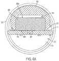
- FIG. 6AThis configuration is further seen in the cross-section of FIG. 6A where the pressure sensor 308 is directly attached to the electronic circuit board 306.
- the sealing member 380surrounds the top and perimeter of the pressure sensor 308 but does not contact the electronic circuit board 306.
- the gap "Y" between the sealing member 380 and the electronic circuit board 306maintains the second end 308b of the pressure sensor 308 within the normal pressure space 373 while the first end 308a of the pressure sensor is within the pressure reduction space 383.
- the direct connection of the pressure sensor to the electronic circuit board 306can encompass a spacing factor, as otherwise discussed herein.
- the second end 308b of the pressure sensor 308may be prevented from forming an air tight seal with the electronic circuit board 306.
- an aperture 307may be formed in the electronic circuit board 306 adjacent the second end 308b of the pressure sensor 306 to provide pressure communication between the second end of the pressure sensor and the normal pressure space 373.
- the coupler 324also can include a pressure channel 385 that opens into the pressure reduction space 383.
- the body end 324a of the coupler 324includes a wall 324c that can include one or more openings or channels therethrough.
- the coupler wall 324ccan include the pressure channel 385 and apertures that accommodate passage of the electrical contact extensions.
- the body end 342a of the coupler 324thus can be described has having a wall 324c through which the pressure channel 385 can extend.
- the connector end 324b of the coupler 324has a cavity 325.
- the cavity 325can be sized and shaped to receive a projection formed in the base of the cartridge (see FIG. 2 ).
- the pressure channelcan extend between a first end 385a that is in fluid communication with the cavity 325 and a second end 385b that opens through the wall 324c at the body end 324a of the coupler 324 to be in fluid communication with the pressure reduction space 383.
- the pressure channelcan be integrally formed in the coupler, although other means of providing the channel also are encompassed. For example, a separate tube can be inserted through the coupler, or an aperture may be created in the coupler body.
- the second end 385b of the pressure channel 385can project into the interior of the shell 301, and the sealing member 380 can substantially surround the perimeter of the second end of the pressure channel.
- the second end 385b of the pressure channel 385may be flush with the wall 324c at the body end 324a of the coupler 324, and a sealing engagement may be made between the sealing member 380 and the wall at the body end of the coupler around the second end of the pressure channel.
- the sealing member 380can be configured to form an air tight seal around the first end 308a of the pressure sensor 308 and the second end 385b of the pressure channel 385.
- the pressure reduction spacecan encompass the opening at the second end 385b of the pressure channel and the first end 308a of the pressure sensor 308.
- the sealing member 380can be in physical contact with an inner surface of the shell 301.
- the coupler 324can include an air inlet channel 388 that can be adapted to distribute drawn, ambient air through an electronic smoking article including the coupler.
- the air inlet channel 388particularly can be in fluid communication with the cavity 325.
- Drawn, ambient aircan enter the air inlet channel 388 through an air inlet aperture 389 that opens through the outer surface of the coupler.
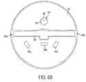
- the configuration of the air inlet channel 388is further illustrated in the cross-section of FIG. 6B where the air inlet channel extends across the diameter of the coupler 324 between a first air inlet aperture 389a and a second air inlet aperture 389b.
- the air inlet aperturesopen through the exterior surface of the coupler and provide an entry for ambient air to be drawn into the coupler to be distributed to other portions of an electronic smoking article utilizing the coupler.
- the air inlet channelmay extend across a portion of the coupler, may be branched, may open to only a single air inlet aperture, or may open to more than two air inlet apertures.
- the air inlet channelcan be formed entirely within the coupler body.
- FIG. 6Bthe pressure sensor 308 can be seen through the pressure channel 385. Also visible through the pressure channel 385 is the interior surface of the sealing member 380 that defines the pressure reduction space 383 at the first end 308a of the pressure sensor 308.
- the cross-section of FIG. 6Bfurther illustrates three openings (386a, 386b, and 386c) through which the electrical contact extensions may pass.
- the first end 385a of the pressure channel 385extends beyond the air inlet channel 388 toward the connector end 324b of the coupler 324.
- the first end 385a of the pressure channel 385is positioned closer to the connector end 324b of the coupler 324 than the air inlet channel 388.
- the first end 385a of the pressure channel 385also can have a diameter that is smaller than the diameter of the second end 385b of the pressure channel.
- the pressure channel 385may increase in diameter from the first end 385a to the second end 385b thereof.
- the coupler 324may define an ambient air flow pathway therethrough.
- the ambient air flow pathwaycan extend from the exterior of the coupler 324 (e.g., through one or more air inlet apertures 389), through the air inlet channel 388 in the coupler body 324, and through the cavity 325.
- the air flow pathwayfurther can extend into a cartridge that is attached to the coupler (such as through a cartridge base, as shown in FIG. 2 ) and out of the cartridge, such as through an opening in an opposing end thereof (see element 228 in FIG. 2 ).
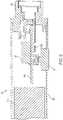
- FIG. 7The spatial relationship of the air inlet channel and the first end of the pressure channel is further illustrated in FIG. 7 .
- a control body 702is engaged with a cartridge 704 via a coupler 724 on the control body and a base 740 on the cartridge.
- the coupler 724includes a cavity 725 that receives a projection 741 on the base 740.
- the cavity 725 and the projection 741each have a stepped configuration such that rings of successively smaller diameter are present in the cavity, and corresponding projection segments of successively smaller diameter are present on the base.
- the projection 741includes an air flow entry 741a that seats in the cavity 725 of the coupler 724 proximate the air inlet channel 788.
- the coupler 724further includes a pressure channel 785 having a first end 785a opening within the cavity 725 of the coupler and a second end 785b opening within the control body 702, particularly within the pressure reduction space 783.
- the first end 785a of the pressure channel 785is spatially arranged relative to the air inlet channel 788 to be separated along the longitudinal axis of the coupler 724 (and thus also the shell 701 of the control body 702).
- the longitudinal separationcan be at least about 1 mm, at least about 2 mm, or at least about 3 mm.
- air draw on the mouthend of the cartridgecauses air to enter the air inlet channel 788 of the coupler 724 through one or more air inlet apertures 789 and flow into the air flow entry 741a of the projection 741 from which the drawn air passes through the interior of the base 740 and into the cartridge 704.
- Air flow through the devicethus can proceed from the air inlet channel 788 downstream toward the mouthend of the cartridge 704.
- the longitudinal separation of the first end 785a of the pressure channel 785 and the air inlet channel 788is such that the first end of the air inlet channel is downstream from the air inlet channel.
- the first end 785a of the pressure channel 785 and the air inlet channel 788are spatially arranged and separated such that the first end of the pressure channel is relatively nearer to the connector end 324b of the coupler.
- the distance between the air flow entry 741 and the first end 785a of the pressure channel 785 when the projection 740 engages the cavity 725can be at least about 1 mm, at least about 2 mm, or at least about 3 mm.
- the air flow entry 741 of the seated projection 740is sufficiently spaced apart from the first end of the pressure channel to prevent or reduce incidence of passage of liquid from the cartridge 704 through the base 740 and into the control body 702.
- an individualmay draw on the mouthend of a cartridge (which may include a mouthpiece), and air flow may be established along an air flow pathway, such as described above.
- Drawn airenters the air inlet channel through the air inlet aperture.
- the air inlet channelcan present a restriction to the flow of air so that the pressure on the interior of the coupler is lower than ambient pressure (and thus lower than the normal pressure space within the control body shell).
- This reduced pressureis transmitted to the pressure sensor in the control body shell by the pressure channel formed in the coupler. In this manner, a pressure differential can be created across the pressure sensor between the first end of the pressure sensor in the pressure reduction space and the second end of the pressure sensor in the normal pressure space within the shell.
- control circuitcan be configured to establish electrical current flow from the electrical power source when the pressure sensor detects a reduced pressure in the pressure reduction space relative to the pressure in the normal pressure space.
- electrical current flowcan energize a heater in the cartridge to vaporize the aerosol precursor composition.
- the spatial arrangement of openings in the couplercan be beneficial in preventing passage of any aerosol precursor composition from a cartridge into the interior of the control body.
- any aerosol formed within the cartridge that is not withdrawn by the usercan condense.
- water vapormay condense within the cartridge and/or liquid stored in a reservoir within the cartridge may leak within the cartridge.
- such liquidscan pass from the cartridge through any air opening that is present to provide passage of drawn air from the control body to the cartridge.
- the air flow passage between the air inlet and the cartridgenecessarily extends through at least a portion of the control body. Any liquid passing out of the cartridge through the air flow passage thus can enter the control body where the liquid can contact the power source, pressure sensor, or control components of the device and cause damage to the control body.
- the air flow entry on the projection of the cartridge's baseis seated upstream from the first end of the pressure channel.
- any liquid passing through the air flow entry in the cartridge's base projectionwould only enter the air inlet channel in the coupler where it can pass out of the coupler through the air inlet aperture or simply flow back into the cartridge.
- the electronic circuit board 306can include a variety of elements in addition to the pressure sensor 308. As illustrated, the electronic circuit board 306 further includes a first light emitting diode (LED) 312a and a second LED 312b. A microprocessor, memory, and the like also may be present on the electronic circuit board. The electronic circuit board may include any elements suitable for establishing a control circuit suitable for controlling one or more functions of an electronic smoking article or the like.
- LEDlight emitting diode
- a microprocessor, memory, and the likealso may be present on the electronic circuit board.
- the electronic circuit boardmay include any elements suitable for establishing a control circuit suitable for controlling one or more functions of an electronic smoking article or the like.
- one or more LEDs on the electronic circuit boardmay be adapted to emit light that is visible exterior to the control body.
- at least a portion of the control body shell and/or the couplercan be translucent or otherwise light transmissive.
- the embodiment of a control body 802 illustrated in FIG. 8comprises an electronic circuit board 806 positioned within a shell 801 between a battery 810 and a coupler 824.
- the electronic circuit board 806is configured lengthwise such that it is substantially parallel with a central axis of the shell 801.
- the electronic circuit board 806comprises a first LED 812a and a second LED 812b.
- the coupler 824is light transmissive such that light from the first LED 812a and/or light from the second LED 812b is visible external to the control body through the coupler.
- the couplermay be formed, for example, from a translucent thermoplastic material.
- the control body 802further can include an input element, such as a pushbutton 861, which can be adapted to activate power delivery from the power source in the control body to a heater, such as in an attached cartridge (see FIG. 2 ).
- the input elementalternatively can be adapted to active a further control function of the device, such as described in greater detail below.
- the coupler 924forms a visible ring around the smoking article 900.
- an LED on the electronic circuit boardis activated, light is emitted through the coupler ring, as shown by the arrows in FIG. 9 .
- the light emittedcan be decorative in nature.
- the control circuitcan be configured to cause at least one LED to emit a defined lighting signal that corresponds to a status of the electronic smoking article.
- the lighting signalcan be defined by a color, a series of different colors, a blinking light of a single color or a series of different colors, or by a specified number of blinks of a light of a single color or a series of different colors.
- the status of the electronic smoking articlecan include any status associated with an electronic smoking article including, but not limited to battery power status, volume of aerosol precursor composition remaining in a cartridge, number of puffs remaining for a cartridge, a working status, an error code, heater activation, or the like.
- the control circuitmay be configured to automatically activate the lighting signal upon detecting a defined input.
- a power depletion inputmay be received by the control circuit, and the control circuit may cause an LED to emit a defined lighting signal to alert the user of the battery status.
- a defined lighting signalmay be automatically activated every time a user draws on the device and activates the heater.
- the control elementmay include programming for activating any number of lighting signals automatically in response to an input.
- the inputmay be an electronic signal that is automatically generated in response to programming of the control circuit.
- the control bodycan include an input element.
- the input elementmay be an element adapted for manual activation by a user.
- a pushbutton 961 as illustrated in FIG. 9is an example of a manual input element.
- a manual input elementmay be a resistive sensing device or a capacitive sensing device including, but not limited to, a touchscreen.
- a manual input elementcan provide an input or a plurality of inputs to the control circuit, which in turn transmits an input to an LED.
- the manual inputmay be adapted to provide one input or a plurality of different inputs to generate a lighting signal indicative of a status of the electronic smoking article.
- a single push of a button or tap on a touchscreenmay generate a lighting signal providing a battery status
- two rapid pushes of the button or taps on the touchscreen in successionmay generate a lighting signal indicating the number of puffs remaining for a cartridge attached to the control body.
- the control elementmay include programming for activating any number of lighting signals in response to a variety of manual inputs to indicate a number of statuses of the device.
- the signal that is output in response to an inputcan vary depending upon the connection status of the control body 902.
- initiating an inputmay provide an output that is a status and/or error code of the control body only.
- initiating an inputmay provide an output that is a status and/or an error code of the cartridge.
- the usermay handle the control body separate from (i.e., unattached) the cartridge and, for example, activate the pushbutton.
- a resulting signal output(e.g., a number of blinks of the light and/or lighting at different colors) can define the battery status. Different numbers of pushes on the push button can elicit different outputs. Further, when a user wished to determine remaining aerosol precursor content in a cartridge, the user may attach the cartridge to the control body and activate the pushbutton (or other input). A resulting signal output can define the content of the aerosol precursor composition. Thus, different outputs can be provided based upon the attachment status of the control body to a cartridge or to a power charger, computing device, or the like.
- an input elemente.g., a pushbutton
- a lighting signal generated as discussed abovemay be visible through the input element as well as the coupler or instead of the coupler.
- a lighting signal indicating one statusmay be visible through the input element, and a lighting signal indicating a second, different status may be visible through the coupler.
- an LEDmay also be positioned at the distal end of the control body shell (see element 212 in FIG. 2 ), and such LED likewise may be adapted to emit a lighting signal. Any status of the control body, a cartridge, or other device connected to a control body may thus be identified by activating an input on the control body and receiving an output based on the connection status of the control body with a further device.
Landscapes
- Engineering & Computer Science (AREA)
- Human Computer Interaction (AREA)
- Manufacture Of Tobacco Products (AREA)
- Health & Medical Sciences (AREA)
- Hematology (AREA)
- General Health & Medical Sciences (AREA)
- Pulmonology (AREA)
- Anesthesiology (AREA)
- Biomedical Technology (AREA)
- Heart & Thoracic Surgery (AREA)
- General Chemical & Material Sciences (AREA)
- Life Sciences & Earth Sciences (AREA)
- Animal Behavior & Ethology (AREA)
- Bioinformatics & Cheminformatics (AREA)
- Public Health (AREA)
- Veterinary Medicine (AREA)
- Chemical & Material Sciences (AREA)
- Chemical Kinetics & Catalysis (AREA)
- Agricultural Chemicals And Associated Chemicals (AREA)
- Disinfection, Sterilisation Or Deodorisation Of Air (AREA)
- Prostheses (AREA)
Abstract
Description
- The present disclosure relates to aerosol delivery devices such as smoking articles. The smoking articles may be configured to heat a material, which may be made or derived from tobacco or otherwise incorporate tobacco, to form an inhalable substance for human consumption.
- Many smoking devices have been proposed through the years as improvements upon, or alternatives to, smoking products that require combusting tobacco for use. Many of those devices purportedly have been designed to provide the sensations associated with cigarette, cigar, or pipe smoking, but without delivering considerable quantities of incomplete combustion and pyrolysis products that result from the burning of tobacco. To this end, there have been proposed numerous smoking products, flavor generators, and medicinal inhalers that utilize electrical energy to vaporize or heat a volatile material, or attempt to provide the sensations of cigarette, cigar, or pipe smoking without burning tobacco to a significant degree. See, for example, the various alternative smoking articles, aerosol delivery devices and heat generating sources set forth in the background art described in
U.S. Pat. No. 7,726,320 to Robinson et al. ,U.S. Pat. Pub. No. 2013/0255702 to Griffith Jr. et al. ,U.S. Pat. Pub. No. 2014/0000638 to Sebastian et al. ,U.S. Pat. App. Ser. No. 13/602,871 to Collett et al., filed September 4, 2012 U.S. Pat. App. Ser. No. 13/647,000 to Sears et al., filed October 8, 2012 U.S. Pat. App. Ser. No. 13/826,929 to Ampolini et al., filed March 14, 2013 U.S. Pat. App. Ser. No. 14/011,992 to Davis et al., filed August 28, 2013 , which are incorporated herein by reference in their entirety. - It would be desirable to provide a smoking article that employs heat produced by electrical energy to provide the sensations of cigarette, cigar, or pipe smoking, that does so without combusting tobacco to any significant degree, that does so without the need of a combustion heat source, and that does so without necessarily delivering considerable quantities of incomplete combustion and pyrolysis products. Further, advances with respect to manufacturing electronic smoking articles would be desirable.
- The present disclosure relates to materials and combinations thereof useful in electronic smoking articles and like personal devices. In particular, the present disclosure relates to a control body that can include one or more elements useful to improve the function thereof.
- The control body particularly can include an electronic circuit board therein that is configured for improved functioning of the device. For example, in some embodiments, the electronic circuit board is in an orientation that provides for improved communication between a pressure sensor and drawn air entering the device. This can incorporate a coupler element that includes an exterior opening that allows external air to enter the device and a pressure channel that communicates a pressure drop caused by the drawn air to an isolated segment of the device that includes a portion of the pressure sensor. Such coupler can particularly be useful to reduce or prevent passage of liquid from an attached cartridge through the coupler and into the control body and thus reduce or prevent contamination of the sensor or other electronic elements present in the control body.
- In some embodiments, a control body for an electronic smoking article according to the present disclosure can comprise an elongated shell with an interior, a proximal end, and an opposing distal end. A coupler can be present and can have a body end that is in engagement with the proximal end of the shell and can have an opposing connector end that is configured to releasably engage a cartridge. An electrical power source can be included as well as an electronic circuit board, which can be positioned within the shell interior between the electrical power source and the coupler. The electronic circuit board particularly can include a control circuit, which can comprise a microcontroller, a microprocessor, or the like, and any further control components suitable for controlling power delivery from the power source and any further functions of the device. Further, the shell can have a central axis therethrough from the proximal end to the distal end, and the electronic circuit board can be oriented parallel to the central axis of the shell.
- In further embodiments, the control body can comprise a pressure sensor attached to the electronic circuit board (i.e., is on the circuit board). The pressure sensor can be attached directly to the electronic circuit board, which can include a spacing factor, as further described herein. The shell interior of the control body can include a normal pressure space and a pressure reduction space, and a first end of the pressure sensor can be in fluid communication with the pressure reduction space while a second end of the pressure sensor can be in fluid communication with the normal pressure space. The body end of the coupler can include a wall, and the connector end of the coupler can have a central opening therethrough. Further, the coupler can include a pressure channel extending between a first end in fluid communication with the central opening and a second end that opens through the wall at the body end of the coupler to be in fluid communication with the pressure reduction space. In some embodiments, the pressure channel can be integrally formed in the coupler. The control body can comprise a sealing member configured to form an air tight seal around the pressure sensor and the second end of the pressure channel and thus define the pressure reduction space encompassing the opening at the second end of the pressure channel and the first end of the pressure sensor. Further, the sealing member can be in physical contact with an inner surface of the shell.
- The coupler can include an air inlet channel in fluid communication with the central opening therein. In some embodiments, the air inlet channel can be formed entirely within the coupler body. An air inlet aperture can be present in the exterior surface of the coupler and be in fluid communication with the air inlet. An ambient air flow pathway can extend from the exterior of the coupler (i.e., through the air inlet aperture), through the coupler body, and through the central opening. The control circuit of the control body can be configured to establish electrical current flow from the electrical power source when the pressure sensor detects a reduced pressure in the pressure reduction space relative to the pressure in the normal pressure space. In some embodiments, the electronic circuit board can be positioned entirely within the normal pressure space.
- In further embodiments, the control body can comprise at least one light emitting diode (LED) attached to the electronic circuit board. At least a portion of the coupler can be light transmissive such that light from the LED is visible through the coupler. Further, the control circuit can be configured to cause an LED to emit a defined lighting signal that corresponds to a status of the electronic smoking article. In some embodiments, the control body can comprise an input element. The control circuit can be configured to cause the at least one LED to emit the defined lighting signal in response to an input from the input element. The input element can be a manual input element (e.g., a pushbutton or touchscreen). In some embodiments, the input element can be at least partially light transmissive. The input to the LED also may be automatically generated by the control circuit in response to detecting a status of the smoking article. If desired, the control body can comprise an LED positioned at the distal end of the shell.
- In other embodiments, a control body for an electronic smoking article can comprise an elongated shell with an interior, a proximal end, and an opposing distal end. The control body further can comprise a coupler formed of an elongated body having a first end that forms a wall and that engages the proximal end of the shell and a second end that comprises a cavity configured to releasably engage a cartridge, wherein the coupler includes a pressure channel extending between a first end that is in fluid communication with the cavity and a second end that opens through the wall at the first end of the coupler, wherein the coupler includes an air inlet channel in fluid communication with the cavity and an air inlet aperture in an exterior surface of the coupler, and wherein the coupler has a longitudinal axis extending from the first end to the second end, and the first end of the pressure channel is spatially separated from the air inlet channel relative to the longitudinal axis of the coupler. The control body further can comprise one or more additional components, such as a power source, a microprocessor or other control component, or the like. In some embodiments, the first end of the pressure channel in the coupler can be spatially separated from the air inlet channel so as to be relatively nearer the second end of the coupler.
- In further embodiments, the present disclosure can provide an electronic smoking article. Such smoking article can comprise a control body as described herein and a cartridge comprising an aerosol precursor composition and a heater adapted to vaporize the aerosol precursor composition.
- The invention includes, without limitation, the following embodiments.
- Embodiment 1: A control body for an electronic smoking article, the control body comprising: an elongated shell with an interior, a proximal end, and an opposing distal end; a coupler having a body end in engagement with the proximal end of the shell and having an opposing connector end configured to releasably engage a cartridge; an electrical power source; and an electronic circuit board positioned within the shell interior between the electrical power source and the coupler; wherein the shell has a central axis therethrough from the proximal end to the distal end, and wherein the electronic circuit board is oriented substantially parallel to the central axis of the shell.
- Embodiment 2: The control body of any preceding or subsequent embodiment, further comprising a pressure sensor attached to the electronic circuit board.
- Embodiment 3: The control body of any preceding or subsequent embodiment, wherein the shell interior includes a normal pressure space and a pressure reduction space, and wherein a first end of the pressure sensor is in fluid communication with the pressure reduction space and a second end of the pressure sensor is in fluid communication with the normal pressure space.
- Embodiment 4: The control body of any preceding or subsequent embodiment, wherein the body end of the coupler forms a wall, the connector end of the coupler has a cavity, and the coupler includes a pressure channel extending between a first end that is in fluid communication with the cavity and a second end that opens through the wall at the body end of the coupler to be in fluid communication with the pressure reduction space.
- Embodiment 5: The control body of any preceding or subsequent embodiment, wherein the pressure channel is integrally formed in the coupler.
- Embodiment 6: The control body of any preceding or subsequent embodiment, comprising a sealing member configured to form an air tight seal around the pressure sensor and the second end of the pressure channel and thus define the pressure reduction space that encompasses the opening at the second end of the pressure channel and the first end of the pressure sensor.
- Embodiment 7: The control body of any preceding or subsequent embodiment, wherein the sealing member is in physical contact with an inner surface of the shell.
- Embodiment 8: The control body of any preceding or subsequent embodiment, wherein the coupler includes an air inlet channel in fluid communication with the cavity.
- Embodiment 9: The control body of any preceding or subsequent embodiment, wherein the air inlet is formed entirely within the coupler body.
- Embodiment 10: The control body of any preceding or subsequent embodiment, comprising an air inlet aperture in the exterior surface of the coupler in fluid communication with the air inlet.
- Embodiment 11: The control body of any preceding or subsequent embodiment, wherein the coupler has a longitudinal axis extending from the body end to the opposing connector end, and wherein the first end of the pressure channel is spatially separated from the air inlet channel relative to the longitudinal axis of the coupler.
- Embodiment 12: The control body of any preceding or subsequent embodiment, wherein the first end of the pressure channel is spatially separated from the air inlet channel so as to be relatively nearer the connector end of the coupler.
- Embodiment 13: The control body of any preceding or subsequent embodiment, comprising an ambient air flow pathway extending from the exterior of the coupler, through the coupler body, and through the cavity.
- Embodiment 14: The control body of any preceding or subsequent embodiment, wherein the electronic circuit board includes a microprocessor, and wherein the microprocessor is configured to establish electrical current flow from the electrical power source when the pressure sensor detects a reduced pressure in the pressure reduction space relative to the pressure in the normal pressure space.
- Embodiment 15: The control body of any preceding or subsequent embodiment, wherein the electronic circuit board is positioned entirely within the normal pressure space.
- Embodiment 16: The control body of any preceding or subsequent embodiment, comprising at least one light emitting diode (LED) attached to the electronic circuit board.
- Embodiment 17: The control body of any preceding or subsequent embodiment, wherein at least a portion of the coupler is light transmissive such that light from the LED is visible through the coupler.
- Embodiment 18: The control body of any preceding or subsequent embodiment, wherein the control circuit is configured to cause the at least one LED to emit a defined lighting signal that corresponds to a status of the electronic smoking article.
- Embodiment 19: The control body of any preceding or subsequent embodiment, comprising an input element, and wherein the control circuit is configured to cause the at least one LED to emit the defined lighting signal in response to an input from the input element.
- Embodiment 20: The control body of any preceding or subsequent embodiment, wherein the input element is at least partially light transmissive.
- Embodiment 21: An electronic smoking article comprising a control body of any preceding or subsequent embodiment and a cartridge comprising an aerosol precursor composition and a heater adapted to vaporize the aerosol precursor composition.
- Embodiment 22: A control body for an electronic smoking article, the control body comprising: an elongated shell with an interior, a proximal end, and an opposing distal end; a coupler formed of an elongated body having a first end that forms a wall and that engages the proximal end of the shell and a second end that comprises a cavity configured to releasably engage a cartridge, wherein the coupler includes a pressure channel extending between a first end that is in fluid communication with the cavity and a second end that opens through the wall at the first end of the coupler, wherein the coupler includes an air inlet channel in fluid communication with the cavity and an air inlet aperture in an exterior surface of the coupler, and wherein the coupler has a longitudinal axis extending from the first end to the second end, and the first end of the pressure channel is spatially separated from the air inlet channel relative to the longitudinal axis of the coupler; and a microprocessor.
- These and other features, aspects, and advantages of the disclosure will be apparent from a reading of the following detailed description together with the accompanying drawings, which are briefly described below. The invention includes any combination of two, three, four, or more of the above-noted embodiments as well as combinations of any two, three, four, or more features or elements set forth in this disclosure, regardless of whether such features or elements are expressly combined in a specific embodiment description herein. This disclosure is intended to be read holistically such that any separable features or elements of the disclosed invention, in any of its various aspects and embodiments, should be viewed as intended to be combinable unless the context clearly dictates otherwise.
- Having thus described the disclosure in the foregoing general terms, reference will now be made to the accompanying drawings, which are not necessarily drawn to scale, and wherein:
FIG. 1 is a sectional view through an electronic smoking article comprising a control body and a cartridge;FIG. 2 is a sectional view through an electronic smoking article comprising a cartridge and a control body according to an example embodiment of the present disclosure;FIG. 3 is a sectional view through a control body of an electronic smoking article according to an example embodiment of the present disclosure;FIG. 4 is a detailed view of the proximal end of the control body illustrated inFIG. 3 ;FIG. 5 is a detailed view of the proximal end of the control body illustrated inFIG. 3 that also illustrates a sealing member;FIG. 6A is a cross-section through Line A - A ofFIG. 5 ;FIG. 6B is a cross-section through Line B - B ofFIG. 5 ;FIG. 7 is a partial sectional view of an electronic smoking article according a further example embodiment of the present disclosure showing a control body connected to a cartridge via the control body coupler and the cartridge base;FIG. 8 is a sectional view of the proximal end a control body of an electronic smoking article according to a further example embodiment of the present disclosure that illustrates an input element; andFIG. 9 is a perspective view of an electronic smoking article according to an example embodiment of the present disclosure showing a control body attached to a cartridge through a light transmissive coupler.- The present disclosure will now be described more fully hereinafter with reference to exemplary embodiments thereof. These exemplary embodiments are described so that this disclosure will be thorough and complete, and will fully convey the scope of the disclosure to those skilled in the art. Indeed, the disclosure may be embodied in many different forms and should not be construed as limited to the embodiments set forth herein; rather, these embodiments are provided so that this disclosure will satisfy applicable legal requirements. As used in the specification, and in the appended claims, the singular forms "a", "an", "the", include plural referents unless the context clearly dictates otherwise.
- The present disclosure provides descriptions of aerosol delivery devices or smoking articles, such as so-called "e-cigarettes." It should be understood that the mechanisms, components, features, and methods may be embodied in many different forms and associated with a variety of articles.
- In this regard, the present disclosure provides descriptions of aerosol delivery devices that use electrical energy to heat a material (preferably without combusting or pyrolyzing the material to any significant degree) to form an inhalable substance; such articles most preferably being sufficiently compact to be considered "hand-held" devices. An aerosol delivery device may provide some or all of the sensations (e.g., inhalation and exhalation rituals, types of tastes or flavors, organoleptic effects, physical feel, use rituals, visual cues such as those provided by visible aerosol, and the like) of smoking a cigarette, cigar, or pipe, without any substantial degree of combustion or pyrolysis of any component of that article or device. The aerosol delivery device may not produce smoke in the sense of the aerosol resulting from by-products of combustion or pyrolysis of tobacco, but rather, that the article or device may yield vapors (including vapors within aerosols that can be considered to be visible aerosols that might be considered to be described as smoke-like) resulting from volatilization or vaporization of certain components of the article or device. In highly preferred embodiments, aerosol delivery devices may incorporate tobacco and/or components derived from tobacco.
- Aerosol delivery devices of the present disclosure also can be characterized as being vapor-producing articles, smoking articles, or medicament delivery articles. Thus, such articles or devices can be adapted so as to provide one or more substances (e.g., flavors and/or pharmaceutical active ingredients) in an inhalable form or state. For example, inhalable substances can be substantially in the form of a vapor (i.e., a substance that is in the gas phase at a temperature lower than its critical point). Alternatively, inhalable substances can be in the form of an aerosol (i.e., a suspension of fine solid particles or liquid droplets in a gas). For purposes of simplicity, the term "aerosol" as used herein is meant to include vapors, gases and aerosols of a form or type suitable for human inhalation, whether or not visible, and whether or not of a form that might be considered to be smoke-like.
- In use, aerosol delivery devices of the present disclosure may be subjected to many of the physical actions employed by an individual in using a traditional type of smoking article (e.g., a cigarette, cigar or pipe that is employed by lighting and inhaling tobacco). For example, the user of an aerosol delivery device of the present disclosure can hold that article much like a traditional type of smoking article, draw on one end of that article for inhalation of aerosol produced by that article, take puffs at selected intervals of time, etc.
- Aerosol delivery devices of the present disclosure generally include a number of components provided within an outer body or shell. The overall design of the outer body or shell can vary, and the format or configuration of the outer body that can define the overall size and shape of the aerosol delivery device can vary. Typically, an elongated body resembling the shape of a cigarette or cigar can be a formed from a single, unitary shell; or the elongated body can be formed of two or more separable pieces. For example, an aerosol delivery device can comprise an elongated shell or body that can be substantially tubular in shape and, as such, resemble the shape of a conventional cigarette or cigar. In one embodiment, all of the components of the aerosol delivery device are contained within one outer body or shell. Alternatively, an aerosol delivery device can comprise two or more shells that are joined and are separable. For example, an aerosol delivery device can possess at one end a control body comprising an outer body or shell containing one or more reusable components (e.g., a rechargeable battery and various electronics for controlling the operation of that article), and at the other end and removably attached thereto an outer body or shell containing a disposable portion (e.g., a disposable flavor-containing cartridge). More specific formats, configurations and arrangements of components within the single shell type of unit or within a multi-piece separable shell type of unit will be evident in light of the further disclosure provided herein. Additionally, various aerosol delivery device designs and component arrangements can be appreciated upon consideration of the commercially available electronic aerosol delivery devices, such as those representative products listed in the background art section of the present disclosure.
- Aerosol delivery devices of the present disclosure most preferably comprise some combination of a power source (i.e., an electrical power source), at least one control component (e.g., means for actuating, controlling, regulating and ceasing power for heat generation, such as by controlling electrical current flow the power source to other components of the article - e.g., a microcontroller), a heater or heat generation component (e.g., an electrical resistance heating element or component commonly referred to as an "atomizer"), an aerosol precursor composition (e.g., commonly a liquid capable of yielding an aerosol upon application of sufficient heat, such as ingredients commonly referred to as "smoke juice," "e-liquid" and "e-juice"), and a mouthend region or tip for allowing draw upon the aerosol delivery device for aerosol inhalation (e.g., a defined air flow path through the article such that aerosol generated can be withdrawn therefrom upon draw). Exemplary formulations for aerosol precursor materials that may be used according to the present disclosure are described in
U.S. Pat. Pub. No. 2013/0008457 to Zheng et al. andU.S. Pat. App. Serial No. 13/536,438 to Sebastian et al., filed Jun. 28, 2012 - Alignment of the components within the aerosol delivery device can vary. In specific embodiments, the aerosol precursor composition can be located near an end of the article (e.g., within a cartridge, which in certain circumstances can be replaceable and disposable), which may be proximal to the mouth of a user so as to maximize aerosol delivery to the user. Other configurations, however, are not excluded. Generally, the heating element can be positioned sufficiently near the aerosol precursor composition so that heat from the heating element can volatilize the aerosol precursor (as well as one or more flavorants, medicaments, or the like that may likewise be provided for delivery to a user) and form an aerosol for delivery to the user. When the heating element heats the aerosol precursor composition, an aerosol is formed, released, or generated in a physical form suitable for inhalation by a consumer. It should be noted that the foregoing terms are meant to be interchangeable such that reference to release, releasing, releases, or released includes form or generate, forming or generating, forms or generates, and formed or generated. Specifically, an inhalable substance is released in the form of a vapor or aerosol or mixture thereof. Additionally, the selection of various aerosol delivery device components can be appreciated upon consideration of the commercially available electronic aerosol delivery devices, such as those representative products listed in the background art section of the present disclosure.
- An aerosol delivery device incorporates a battery or other electrical power source to provide current flow sufficient to provide various functionalities to the article, such as resistive heating, powering of control systems, powering of indicators, and the like. The power source can take on various embodiments. Preferably, the power source is able to deliver sufficient power to rapidly heat the heating member to provide for aerosol formation and power the article through use for the desired duration of time. The power source preferably is sized to fit conveniently within the aerosol delivery device so that the aerosol delivery device can be easily handled; and additionally, a preferred power source is of a sufficiently light weight to not detract from a desirable smoking experience.
- One example embodiment of an
aerosol delivery device 100 is provided inFIG. 1 . As seen in the cross-section illustrated therein, theaerosol delivery device 100 can comprise acontrol body 102 and acartridge 104 that can be permanently or detachably aligned in a functioning relationship. Although a threaded engagement is illustrated inFIG. 1 , it is understood that further means of engagement may be employed, such as a press-fit engagement, interference fit, a magnetic engagement, or the like. In particular, connection components, such as further described herein may be used. For example, the control body may include a coupler that is adapted to engage a connector on the cartridge. Such couplers and connectors are further discussed herein. - In specific embodiments, one or both of the
control body 102 and thecartridge 104 may be referred to as being disposable or as being reusable. For example, the control body may have a replaceable battery or a rechargeable battery and thus may be combined with any type of recharging technology, including connection to a typical electrical outlet, connection to a car charger (i.e., cigarette lighter receptacle), and connection to a computer, such as through a universal serial bus (USB) cable. For example, an adaptor including a USB connector at one end and a control body connector at an opposing end is disclosed inU.S. Pat. App. Serial No. 13/840,264 to Novak et al., filed Mar. 15, 2013 U.S. Pat. App. Serial No. 13/603,612 to Chang et al., filed September 5, 2012 - In the exemplified embodiment, the
control body 102 includes a control component 106 (e.g., a microcontroller), aflow sensor 108, and abattery 110, which can be variably aligned, and can include a plurality ofindicators 112 at adistal end 114 of anouter body 116. Theindicators 112 can be provided in varying numbers and can take on different shapes and can even be an opening in the body (such as for release of sound when such indicators are present). In the exemplified embodiment, ahaptic feedback component 101 is included with thecontrol component 106. As such, the haptic feedback component may be integrated with one or more components of a smoking article for providing vibration or like tactile indication of use or status to a user. See, for example, the disclosure ofU.S. Pat. App. Serial No. 13/946,309 to Galloway et al., filed July 19, 2013 - An
air intake 118 may be positioned in theouter body 116 of thecontrol body 102. Acoupler 120 also is included at theproximal attachment end 122 of thecontrol body 102 and may extend into acontrol body projection 124 to allow for ease of electrical connection with an atomizer or a component thereof, such as a resistive heating element (described below) when thecartridge 104 is attached to the control body. Although theair intake 118 is illustrated as being provided in theouter body 116, in another embodiment the air intake may be provided in a coupler as described, for example, inU.S. Pat. App. Serial No. 13/841,233 to DePiano et al., filed March 15, 2013 - The
cartridge 104 includes anouter body 126 with amouth opening 128 at amouthend 130 thereof to allow passage of air and entrained vapor (i.e., the components of the aerosol precursor composition in an inhalable form) from the cartridge to a consumer during draw on theaerosol delivery device 100. Theaerosol delivery device 100 may be substantially rod-like or substantially tubular shaped or substantially cylindrically shaped in some embodiments. In other embodiments, further shapes and dimensions are encompassed - e.g., a rectangular or triangular cross-section, or the like. - The
cartridge 104 further includes anatomizer 132 comprising a resistive heating element 134 (e.g., a wire coil) configured to produce heat and a liquid transport element 136 (e.g., a wick) configured to transport a liquid. Various embodiments of materials configured to produce heat when electrical current is applied therethrough may be employed to form theresistive heating element 134. Example materials from which the wire coil may be formed include Kanthal (FeCrAl), Nichrome, Molybdenum disilicide (MoSi2), molybdenum silicide (MoSi), Molybdenum disilicide doped with Aluminum (Mo(Si,Al)2), and ceramic (e.g., a positive temperature coefficient ceramic). Further to the above, representative heating elements and materials for use therein are described inU.S. Pat. No. 5,060,671 to Counts et al. ;U.S. Pat. No. 5,093,894 to Deevi et al. ;U.S. Pat. No. 5,224,498 to Deevi et al. ;U.S. Pat. No. 5,228,460 to Sprinkel Jr., et al. ;U.S. Pat. No. 5,322,075 to Deevi et al. ;U.S. Pat. No. 5,353,813 to Deevi et al. ;U.S. Pat. No. 5,468,936 to Deevi et al. ;U.S. Pat. No. 5,498,850 to Das ;U.S. Pat. No. 5,659,656 to Das ;U.S. Pat. No. 5,498,855 to Deevi et al. ;U.S. Pat. No. 5,530,225 to Hajaligol ;U.S. Pat. No. 5,665,262 to Hajaligol ;U.S. Pat. No. 5,573,692 to Das et al. ; andU.S. Pat. No. 5,591,368 to Fleischhauer et al. , the disclosures of which are incorporated herein by reference in their entireties. - Electrically conductive heater terminals 138 (e.g., positive and negative terminals) at the opposing ends of the
heating element 134 are configured to direct current flow through the heating element and configured for attachment to the appropriate wiring or circuit (not illustrated) to form an electrical connection of the heating element with thebattery 110 when thecartridge 104 is connected to thecontrol body 102. Specifically, aplug 140 may be positioned at adistal attachment end 142 of thecartridge 104. When thecartridge 104 is connected to thecontrol body 102, theplug 140 engages thecoupler 120 to form an electrical connection such that current controllably flows from thebattery 110, through the coupler and plug, and to theheating element 134. Theouter body 126 of thecartridge 104 can continue across thedistal attachment end 142 such that this end of the cartridge is substantially closed with theplug 140 protruding therefrom. - A liquid transport element can be combined with a reservoir to transport an aerosol precursor composition to an aerosolization zone. In the embodiment shown in
FIG. 1 , thecartridge 104 includes areservoir layer 144 comprising layers of nonwoven fibers formed into the shape of a tube encircling the interior of theouter body 126 of the cartridge, in this embodiment. An aerosol precursor composition is retained in thereservoir layer 144. Liquid components, for example, can be sorptively retained by thereservoir layer 144. Thereservoir layer 144 is in fluid connection with aliquid transport element 136. Theliquid transport element 136 transports the aerosol precursor composition stored in thereservoir layer 144 via capillary action to anaerosolization zone 146 of thecartridge 104. As illustrated, theliquid transport element 136 is in direct contact with theheating element 134 that is in the form of a metal wire coil in this embodiment. - It is understood that an aerosol delivery device that can be manufactured according to the present disclosure can encompass a variety of combinations of components useful in forming an electronic aerosol delivery device. Reference is made for example to the reservoir and heater system for controllable delivery of multiple aerosolizable materials in an electronic smoking article disclosed in
U.S. Pat. App. Serial No. 13/536,438 to Sebastian et al., filed June 28, 2012 U.S. Pat. App. Serial No. 13/602,871 to Collett et al., filed September 4, 2012 - Reference also is made to
U.S. Pat. Pub. No. 2013/0213419 to Tucker et al. , which discloses a ribbon of electrically resistive mesh material that may be wound around a wick, and toU.S. Pat. Pub. No. 2013/0192619 to Tucker et al. , which discloses a heater coil about a wick wherein the coil windings have substantially uniform spacing between each winding. In certain embodiments according to the present disclosure, a heater may comprise a metal wire, which may be wound with a varying pitch around a liquid transport element, such as a wick. An exemplary variable pitch heater that may be used according to the present disclosure is described inU.S. Pat. App. Serial No. 13/827,994 to DePiano et al., filed March 14, 2013 - Reference also is made to a liquid supply reservoir formed of an elastomeric material and adapted to be manually compressed so as to pump liquid material therefrom, as disclosed in
U.S. Pat. Pub. No. 2013/0213418 to Tucker et al. In certain embodiments according to the present disclosure, a reservoir may particularly be formed of a fibrous material, such as a fibrous mat or tube that may absorb or adsorb a liquid material. - In another embodiment substantially the entirety of the cartridge may be formed from one or more carbon materials, which may provide advantages in terms of biodegradability and absence of wires. In this regard, the heating element may comprise a carbon foam, the reservoir may comprise carbonized fabric, and graphite may be employed to form an electrical connection with the battery and controller. Such carbon cartridge may be combined with one or more elements as described herein for providing illumination of the cartridge in some embodiments. An example embodiment of a carbon-based cartridge is provided in
U.S. Pat. Pub. No. 2013/0255702 to Griffith Jr. et al. , which is incorporated herein by reference in its entirety. - In use, when a user draws on the
article 100, theheating element 134 is activated (e.g., such as via a flow sensor), and the components for the aerosol precursor composition are vaporized in theaerosolization zone 146. Drawing upon themouthend 130 of thearticle 100 causes ambient air to enter theair intake 118 and pass through the central opening in thecoupler 120 and the central opening in theplug 140. In thecartridge 104, the drawn air passes through anair passage 148 in anair passage tube 150 and combines with the formed vapor in theaerosolization zone 146 to form an aerosol. The aerosol is whisked away from theaerosolization zone 146, passes through anair passage 152 in anair passage tube 154, and out themouth opening 128 in themouthend 130 of thearticle 100. - The various components of an aerosol delivery device according to the present disclosure can be chosen from components described in the art and commercially available. Examples of batteries that can be used according to the disclosure are described in
U.S. Pat. App. Pub. No. 2010/0028766 to Peckerar et al. , the disclosure of which is incorporated herein by reference in its entirety. - An exemplary mechanism that can provide puff-actuation capability includes a Model 163PC01D36 silicon sensor, manufactured by the MicroSwitch division of Honeywell, Inc., Freeport, Ill. Further examples of demand-operated electrical switches that may be employed in a heating circuit according to the present disclosure are described in
U.S. Pat. No. 4,735,217 to Gerth et al. , which is incorporated herein by reference in its entirety. Further description of current regulating circuits and other control components, including microcontrollers that can be useful in the present aerosol delivery device, are provided inU.S. Pat. Nos. 4,922,901 ,4,947,874 , and4,947,875, all to Brooks et al. ,U.S. Pat. No. 5,372,148 to McCafferty et al. ,U.S. Pat. No. 6,040,560 to Fleischhauer et al. , andU.S. Pat. No. 7,040,314 to Nguyen et al. , all of which are incorporated herein by reference in their entireties. - Reference also is made to International Publications
WO 2013/098396 to Talon ,WO 2013/098397 to Talon , andWO 2013/098398 to Talon , which describe controllers configured to control power supplied to a heater element from a power source as a means to monitor a status of the device, such as heater temperature, air flow past a heater, and presence of an aerosol forming material near a heater. In particular embodiments, the present disclosure provides a variety of control systems adapted to monitor status indicators, such as through communication of a microcontroller in a control body and a microcontroller or other electronic component in a cartridge component. - The aerosol precursor, which may also be referred to as an aerosol precursor composition or a vapor precursor composition, can comprise one or more different components. For example, the aerosol precursor can include a polyhydric alcohol (e.g., glycerin, propylene glycol, or a mixture thereof). Representative types of further aerosol precursor compositions are set forth in
U.S. Pat. No. 4,793,365 to Sensabaugh, Jr. et al. ;U.S. Pat. No. 5,101,839 to Jakob et al. ;WO 98/57556 to Biggs et al. - Still further components can be utilized in the aerosol delivery device of the present disclosure. For example,
U.S. Pat. No. 5,154,192 to Sprinkel et al. discloses indicators that may be used with smoking articles;U.S. Pat. No. 5,261,424 to Sprinkel, Jr. discloses piezoelectric sensors that can be associated with the mouth-end of a device to detect user lip activity associated with taking a draw and then trigger heating;U.S. Pat. No. 5,372,148 to McCafferty et al. discloses a puff sensor for controlling energy flow into a heating load array in response to pressure drop through a mouthpiece;U.S. Pat. No. 5,967,148 to Harris et al. discloses receptacles in a smoking device that include an identifier that detects a non-uniformity in infrared transmissivity of an inserted component and a controller that executes a detection routine as the component is inserted into the receptacle;U.S. Pat. No. 6,040,560 to Fleischhauer et al. describes a defined executable power cycle with multiple differential phases;U.S. Pat. No. 5,934,289 to Watkins et al. discloses photonic-optronic components;U.S. Pat. No. 5,954,979 to Counts et al. discloses means for altering draw resistance through a smoking device;U.S. Pat. No. 6,803,545 to Blake et al. discloses specific battery configurations for use in smoking devices;U.S. Pat. No. 7,293,565 to Griffen et al. discloses various charging systems for use with smoking devices;U.S. Pat. No. 8,402,976 to Fernando et al. discloses computer interfacing means for smoking devices to facilitate charging and allow computer control of the device;U.S. Pat. App. Pub. No. 2010/0163063 by Fernando et al. discloses identification systems for smoking devices; andWO 2010/003480 by Flick discloses a fluid flow sensing system indicative of a puff in an aerosol generating system; all of the foregoing disclosures being incorporated herein by reference in their entireties. Further examples of components related to electronic aerosol delivery articles and disclosing materials or components that may be used in the present article includeU.S. Pat. No. 4,735,217 to Gerth et al. ;U.S. Pat. No. 5,249,586 to Morgan et al. ;U.S. Pat. No. 5,388,574 to Ingebrethsen ;U.S. Pat. No. 5,666,977 to Higgins et al. ;U.S. Pat. No. 6,053,176 to Adams et al. ;U.S. 6,164,287 to White ;U.S. Pat No. 6,196,218 to Voges ;U.S. Pat. No. 6,810,883 to Felter et al. ;U.S. Pat. No. 6,854,461 to Nichols ;U.S. Pat. No. 7,832,410 to Hon ;U.S. Pat. No. 7,513,253 to Kobayashi ;U.S. Pat. No. 7,896,006 to Hamano ;U.S. Pat. No. 6,772,756 to Shayan ;U.S. Pat. No. 8,156,944 to Hon ;U.S. Pat. No. 8,365,742 to Hon ;U.S. Pat. No. 8,375,957 to Hon ;U.S. Pat. No. 8,393,331 to Hon ;U.S. Pat. App. Pub. Nos. 2006/0196518 and2009/0188490 to Hon ;U.S. Pat. App. Pub. No. 2009/0272379 to Thorens et al. ;U.S. Pat. App. Pub. Nos. 2009/0260641 and2009/0260642 to Monsees et al. ;U.S. Pat. App. Pub. Nos. 2008/0149118 and2010/0024834 to Oglesby et al. ;U.S. Pat. App. Pub. No. 2010/0307518 to Wang ;WO 2010/091593 to Hon ;WO 2013/089551 to Foo ; andU.S. Pat. Pub. No. 2013/0037041 to Worm et al. , each of which is incorporated herein by reference in its entirety. A variety of the materials disclosed by the foregoing documents may be incorporated into the present devices in various embodiments, and all of the foregoing disclosures are incorporated herein by reference in their entireties. - The foregoing description of use of the article can be applied to the various embodiments described herein through minor modifications, which can be apparent to the person of skill in the art in light of the further disclosure provided herein. The above description of use, however, is not intended to limit the use of the article but is provided to comply with all necessary requirements of disclosure of the present disclosure.
- In various embodiments according to the present disclosure, an electronic smoking article, particularly a cartridge thereof, may include a reservoir housing, which can be used in addition to, or in the absence of, a porous medium. For example, a porous medium, such as the fibrous mat material, may be present inside the reservoir housing. Alternatively, the reservoir housing may form the reservoir in the absence of any porous medium inside the reservoir housing. Electronic smoking articles incorporating reservoir housings are particularly described in
U.S. Pat. App. No. 14/087,594 to Chang et al., filed Nov. 22, 2013 , the disclosure of which is incorporated herein by reference in its entirety. - Any of the elements shown in the article illustrated in
FIG. 1 or as otherwise described above may be included in a smoking article according to the present disclosure. In particular, any of the above described and illustrated components of a control body can be incorporated into a control body according to the present disclosure - An exemplary embodiment of a
smoking article 200 according to the present disclosure is shown inFIG. 2 . As illustrated therein, acontrol body 202 can be formed of acontrol body shell 201 that can include acontrol component 206, aflow sensor 208, abattery 210, and anLED 212. Acartridge 204 can be formed of acartridge shell 203 enclosing thereservoir housing 244 that is in fluid communication with aliquid transport element 236 adapted to wick or otherwise transport an aerosol precursor composition stored in the reservoir housing to aheater 234. Anopening 228 may be present in thecartridge shell 203 to allow for egress of formed aerosol from thecartridge 204. Such components are representative of the components that may be present in a cartridge and are not intended to limit the scope of cartridge components that are encompassed by the present disclosure. - Although the
control component 206 and theflow sensor 208 are illustrated separately, it is understood that the control component and the flow sensor may be combined as an electronic circuit board with the air flow sensor attached directly thereto. Further, the electronic circuit board may be positioned horizontally relative the illustration ofFIG. 2 in that the electronic circuit board can be lengthwise parallel to the central axis of the control body. - The
cartridge 204 also may include one or moreelectronic components 250, which may include an IC, a memory component, a sensor, or the like. Theelectronic component 250 may be adapted to communicate with thecontrol component 206. - The
control body 202 and thecartridge 204 may include components adapted to facilitate a fluid engagement therebetween. As illustrated inFIG. 2 , thecontrol body 202 can include acoupler 224 having acavity 225 therein. Thecartridge 204 can include a base 240 adapted to engage thecoupler 224 and can include aprojection 241 adapted to fit within thecavity 225. Such engagement can facilitate a stable connection between thecontrol body 202 and thecartridge 204 as well as establish an electrical connection between thebattery 210 andcontrol component 206 in the control body and theheater 234 in the cartridge. Further, thecontrol body shell 201 can include anair intake 218, which may be a notch in the shell where it connects to thecoupler 224 that allows for passage of ambient air around the coupler and into the shell where it then passes through thecavity 225 of the coupler and into the cartridge through theprojection 241. - A coupler and a base useful according to the present disclosure are described in
U.S. Pat. App. No. 13/840,264 to Novak et al., filed Mar. 15, 2013 FIG. 2 may define anouter periphery 226 configured to mate with aninner periphery 242 of thebase 240. In one embodiment the inner periphery of the base may define a radius that is substantially equal to, or slightly greater than, a radius of the outer periphery of the coupler. Further, thecoupler 224 may define one ormore protrusions 229 at theouter periphery 226 configured to engage one ormore recesses 278 defined at the inner periphery of the base. However, various other embodiments of structures, shapes, and components may be employed to couple the base to the coupler. In some embodiments the connection between the base 240 of thecartridge 204 and thecoupler 224 of thecontrol body 202 may be substantially permanent, whereas in other embodiments the connection therebetween may be releasable such that, for example, the control body may be reused with one or more additional cartridges that may be disposable and/or refillable. - The coupler may further comprise a plurality of electrical contacts configured to contact terminals associated with the base projection. The electrical contacts may be positioned at differing radial distances in the
cavity 225 of thecoupler 224 and positioned at differing depths within the coupler. The depth and radius of each of the electrical contacts is configured such that the end of the terminals come into contact therewith when the base and the coupler are joined together to establish an electrical connection therebetween. For example, a first electrical contact can define the smallest diameter, a third electrical contact can define the greatest diameter, and a second electrical contact can define a diameter therebetween. Further, the electrical contacts can be located at differing depths within the connector relative to a connector end thereof. For example, a first electrical contact can be located at a greatest depth, a third electrical contract can be located at a smallest depth, and a second electrical contact can be located at a depth therebetween. The electrical contacts may comprise circular metal bands of varying radii positioned at differing depths within the coupler. See, for example, the electrical contacts illustrated inFIG. 4 . - In particular embodiments according to the present disclosure, the coupler utilized with the shell of the control body may be configured to provide for additional or improved functionalities, particularly in relation to communications between the coupler and a control component within the control body. This can arise from a desired configuration of an electronic circuit board within the shell in relation to the coupler. For example, referring to
FIG. 3 , acontrol body 302 useful with an electronic smoking article can comprise ashell 301 with an interior 303, aproximal end 322, and an opposingdistal end 314. Thecontrol body 302 further includes acoupler 324 having abody end 324a in engagement with theproximal end 322 of theshell 302 and an opposingconnector end 324b configured to releasably engage a cartridge. Anend cap 311 is shown engaging thedistal end 314 of theshell 302. Thecontrol body 302 also includes abattery 310 and anelectronic circuit board 306 positioned within theinterior 303 of theshell 301 between thebattery 310 and thecoupler 324. The electronic circuit board can include a control circuit, memory, microprocessors, and/or the like. As illustrated inFIG. 3 , theshell 301 has a central axis extending along the length of theshell 301. In some embodiments, theelectronic circuit board 306 can be oriented as illustrated inFIG. 3 to be substantially parallel to the central axis of theshell 301. In other words, the electronic circuit board can have a thickness and a length such that the length is greater than the thickness, and the electronic circuit board can be positioned lengthwise within the shell to be substantially parallel to the central axis of the shell. An electronic circuit board can be considered to be substantially parallel to the central axis of the shell when the alignment deviates from parallel by less than 45 degrees, less than 30 degrees, or less than 15 degrees. In such alignment, the functional surface(s) of the electronic circuit board to which working components may be attached face the shell wall, and thus the functional surface(s) of the electronic circuit board is substantially perpendicular to the central axis of the shell. In embodiments wherein an electronic circuit board is positioned substantially perpendicular to the central axis of the shell, the surface area of the electronic circuit board to which components may be attached can be limited. As illustrated inFIG. 3 , however, positioning the electronic circuit board to be substantially parallel to the central axis of the shell makes a most efficient use of space within the shell and allows for an increased surface area for the electronic circuit board for attachment of components, such as a microprocessor, LED's, and other control components. - The
electronic circuit board 306 can include apressure sensor 308 attached directly thereto. A direct attachment in this sense is intended to mean a connection whereby the pressure sensor can be electrically connected to the electronic circuit board via integrated components (e.g., pins) as opposed to a wired connection. Previous devices incorporating a pressure sensor and an electronic circuit typically have the pressure sensor spaced a significant distance from the electronic circuit board, and the electrical connection therebetween is formed using wires attached to the pressure sensor and the electronic circuit board. In the present configurations, the need for a wired connection between an electronic circuit board and a pressure sensor can be eliminated. This can reduce expense associated with hand soldering of wired connections and improve reliability associated with the assembly process. In some embodiments, a direct connection can encompass the use of an intermediate attachment element or spacer (e.g., a spacer attached directly to the electronic circuit board and a pressure sensor attached directly to the spacer). The direct attachment can mean that the electrical contacts or pins of the pressure sensor are in direct contact with the electronic circuit board although the body of the pressure sensor may be spaced apart from the electronic circuit board. A substantially direct attachment between the pressure sensor and the electronic circuit board can encompass any attachment whereby the body of the pressure sensor is spaced apart from the electronic circuit board by less than 50% of the diameter of theshell 301, less than 25% of the diameter of the shell, less than 10% of the diameter of the shell, or less than 5% of the diameter of the shell. For example, the spacing can 5 mm or less, 2 mm or less, or 1 mm or less. As illustrated, thepressure sensor 308 has a central axis extending between a first, free end and a second end attached to the electronic circuit board 306 (308a and 308b, as illustrated inFIG. 5 ). This central axis of thepressure sensor 308 is substantially perpendicular to the central axis of theshell 301. - The positioning of the electronic circuit board is more clearly seen in the partial section shown in
FIG. 4 . As seen therein, theelectronic circuit board 306 is positioned within theshell 301 between thebattery 310 and thecoupler 324 such that the lengthwise axis of the electronic circuit board is substantially parallel to the central axis of the shell. As such, theelectronic circuit board 306 has afirst end 306a that is adjacent thecoupler 324 and asecond end 306b that is adjacent thebattery 310. The electronic circuit board may be at least partially within the coupler. As such, the electronic circuit board may be attached (e.g., interference fit, glued, or otherwise affixed) to the coupler. Alternatively, the electronic circuit board may be interconnected with the coupler through an intermediate attachment, such as theextension 361a of the first electrical contact 361 (as more fully discussed below). - In the embodiment illustrated, the
first end 306a of theelectronic circuit board 306 is located within thecoupler 324, and this can provide various advantages as is evident from the further disclosure herein. For example, such location can facilitate ease of connection between the electronic circuit board and the electrical contacts in the coupler. As seen inFIG. 4 , a firstelectrical contact 361, a secondelectrical contact 362, and a thirdelectrical contact 363 are provided as bands encircling the central opening 325 (or cavity) in theconnector end 324b of thecoupler 324. Visible inFIG. 4 is anextension 361a of the firstelectrical contact 361 extending between the contact and theelectronic circuit board 306 and passing through thecoupler 324. A second electrical contact extension and a third electrical contact extension also are present but not visible in the illustration. - The orientation of the electronic circuit board also is beneficial in that the
interior 303 of theshell 301 can be partitioned into different spaces or sections that can experience different pressures. For example, the shell interior can include a normal pressure space and a pressure reduction space. The normal pressure space can be maintained at ambient pressure and experience no significant change in pressure related to use of the control body in an electronic smoking article. Normal pressure can be maintained with an opening in theshell 301 to the surrounding atmosphere. For example, theend cap 311 can be arranged to allow communication between the normal pressure space of the shell and the surrounding atmosphere. Such pressure communication between the normal pressure space and the surrounding atmosphere can be facilitated with an opening located elsewhere on theshell 301 and/or around the connection of thecoupler 324 with the shell. The pressure reduction space can be isolated from the normal pressure space, and the pressure within the pressure reduction space can be reduced below the pressure in the normal pressure space during use of the article (i.e., during draw on the article). - In the embodiment illustrated in
FIG. 5 , afirst end 308a of thepressure sensor 308 can be positioned to be in fluid communication with thepressure reduction space 383, and asecond end 308b of the pressure sensor can be positioned to be in fluid communication with thenormal pressure space 373. In some embodiments, the pressure reduction space can be defined by a sealingmember 380. For example, the sealing member can comprise a silicone rubber or like material. In some embodiments, the sealing member may be a cup seal. The sealingmember 380 can substantially surround the perimeter of thepressure sensor 308 and be in a sealing contact therewith. As illustrated, thepressure sensor 308 is directly attached to theelectronic circuit board 306, but the sealingmember 380 does not extend completely down the length of the pressure sensor and thus does not form a sealing contact with the electronic circuit board. As such, thesecond end 308b of thepressure sensor 308 and theelectronic circuit board 306 are positioned within thenormal pressure space 373. - This configuration is further seen in the cross-section of
FIG. 6A where thepressure sensor 308 is directly attached to theelectronic circuit board 306. The sealingmember 380 surrounds the top and perimeter of thepressure sensor 308 but does not contact theelectronic circuit board 306. The gap "Y" between the sealingmember 380 and theelectronic circuit board 306 maintains thesecond end 308b of thepressure sensor 308 within thenormal pressure space 373 while thefirst end 308a of the pressure sensor is within thepressure reduction space 383. To ensure that thesecond end 308b of thepressure sensor 308 is maintained at ambient pressure, the direct connection of the pressure sensor to theelectronic circuit board 306 can encompass a spacing factor, as otherwise discussed herein. As such, thesecond end 308b of thepressure sensor 308 may be prevented from forming an air tight seal with theelectronic circuit board 306. Alternatively or in combination, anaperture 307 may be formed in theelectronic circuit board 306 adjacent thesecond end 308b of thepressure sensor 306 to provide pressure communication between the second end of the pressure sensor and thenormal pressure space 373. - The
coupler 324 also can include apressure channel 385 that opens into thepressure reduction space 383. As illustrated in the embodiment ofFIG. 5 , thebody end 324a of thecoupler 324 includes awall 324c that can include one or more openings or channels therethrough. For example, thecoupler wall 324c can include thepressure channel 385 and apertures that accommodate passage of the electrical contact extensions. The body end 342a of thecoupler 324 thus can be described has having awall 324c through which thepressure channel 385 can extend. - The
connector end 324b of thecoupler 324 has acavity 325. Thecavity 325 can be sized and shaped to receive a projection formed in the base of the cartridge (seeFIG. 2 ). More particularly, the pressure channel can extend between afirst end 385a that is in fluid communication with thecavity 325 and asecond end 385b that opens through thewall 324c at thebody end 324a of thecoupler 324 to be in fluid communication with thepressure reduction space 383. The pressure channel can be integrally formed in the coupler, although other means of providing the channel also are encompassed. For example, a separate tube can be inserted through the coupler, or an aperture may be created in the coupler body. - As seen in
FIG. 5 , thesecond end 385b of thepressure channel 385 can project into the interior of theshell 301, and the sealingmember 380 can substantially surround the perimeter of the second end of the pressure channel. Thesecond end 385b of thepressure channel 385 may be flush with thewall 324c at thebody end 324a of thecoupler 324, and a sealing engagement may be made between the sealingmember 380 and the wall at the body end of the coupler around the second end of the pressure channel. The sealingmember 380 can be configured to form an air tight seal around thefirst end 308a of thepressure sensor 308 and thesecond end 385b of thepressure channel 385. The pressure reduction space can encompass the opening at thesecond end 385b of the pressure channel and thefirst end 308a of thepressure sensor 308. In some embodiments, the sealingmember 380 can be in physical contact with an inner surface of theshell 301. - In some embodiments, the
coupler 324 can include anair inlet channel 388 that can be adapted to distribute drawn, ambient air through an electronic smoking article including the coupler. Theair inlet channel 388 particularly can be in fluid communication with thecavity 325. Drawn, ambient air can enter theair inlet channel 388 through anair inlet aperture 389 that opens through the outer surface of the coupler. - The configuration of the
air inlet channel 388 is further illustrated in the cross-section ofFIG. 6B where the air inlet channel extends across the diameter of thecoupler 324 between a firstair inlet aperture 389a and a secondair inlet aperture 389b. The air inlet apertures open through the exterior surface of the coupler and provide an entry for ambient air to be drawn into the coupler to be distributed to other portions of an electronic smoking article utilizing the coupler. In other embodiments, the air inlet channel may extend across a portion of the coupler, may be branched, may open to only a single air inlet aperture, or may open to more than two air inlet apertures. In some embodiments, the air inlet channel can be formed entirely within the coupler body. - In
FIG. 6B , thepressure sensor 308 can be seen through thepressure channel 385. Also visible through thepressure channel 385 is the interior surface of the sealingmember 380 that defines thepressure reduction space 383 at thefirst end 308a of thepressure sensor 308. The cross-section ofFIG. 6B further illustrates three openings (386a, 386b, and 386c) through which the electrical contact extensions may pass. - As seen in
FIG. 5 , thefirst end 385a of thepressure channel 385 extends beyond theair inlet channel 388 toward theconnector end 324b of thecoupler 324. In other words, thefirst end 385a of thepressure channel 385 is positioned closer to theconnector end 324b of thecoupler 324 than theair inlet channel 388. This configuration can be useful to prevent backflow of liquids or vapors into the control body. Thefirst end 385a of thepressure channel 385 also can have a diameter that is smaller than the diameter of thesecond end 385b of the pressure channel. Similarly, thepressure channel 385 may increase in diameter from thefirst end 385a to thesecond end 385b thereof. - In light of the above-described configuration, the
coupler 324 may define an ambient air flow pathway therethrough. In some embodiments, the ambient air flow pathway can extend from the exterior of the coupler 324 (e.g., through one or more air inlet apertures 389), through theair inlet channel 388 in thecoupler body 324, and through thecavity 325. The air flow pathway further can extend into a cartridge that is attached to the coupler (such as through a cartridge base, as shown inFIG. 2 ) and out of the cartridge, such as through an opening in an opposing end thereof (seeelement 228 inFIG. 2 ). - The spatial relationship of the air inlet channel and the first end of the pressure channel is further illustrated in
FIG. 7 . As seen therein, acontrol body 702 is engaged with acartridge 704 via acoupler 724 on the control body and a base 740 on the cartridge. Thecoupler 724 includes acavity 725 that receives aprojection 741 on thebase 740. As illustrated, thecavity 725 and theprojection 741 each have a stepped configuration such that rings of successively smaller diameter are present in the cavity, and corresponding projection segments of successively smaller diameter are present on the base. Theprojection 741 includes anair flow entry 741a that seats in thecavity 725 of thecoupler 724 proximate theair inlet channel 788. Thecoupler 724 further includes apressure channel 785 having afirst end 785a opening within thecavity 725 of the coupler and asecond end 785b opening within thecontrol body 702, particularly within thepressure reduction space 783. Thefirst end 785a of thepressure channel 785 is spatially arranged relative to theair inlet channel 788 to be separated along the longitudinal axis of the coupler 724 (and thus also theshell 701 of the control body 702). The longitudinal separation can be at least about 1 mm, at least about 2 mm, or at least about 3 mm. - When the
cartridge 704 engages thecontrol body 702, air draw on the mouthend of the cartridge (seeelement 130 inFIG. 1 ) causes air to enter theair inlet channel 788 of thecoupler 724 through one or moreair inlet apertures 789 and flow into theair flow entry 741a of theprojection 741 from which the drawn air passes through the interior of thebase 740 and into thecartridge 704. Air flow through the device thus can proceed from theair inlet channel 788 downstream toward the mouthend of thecartridge 704. The longitudinal separation of thefirst end 785a of thepressure channel 785 and theair inlet channel 788 is such that the first end of the air inlet channel is downstream from the air inlet channel. In other words, thefirst end 785a of thepressure channel 785 and theair inlet channel 788 are spatially arranged and separated such that the first end of the pressure channel is relatively nearer to theconnector end 324b of the coupler. Likewise, when theprojection 741 of thebase 740 engages thecavity 725 of thecoupler 724, theair flow entry 741 seats upstream in the cavity from thefirst end 785a of thepressure channel 785. As such, the distance between theair flow entry 741 and thefirst end 785a of thepressure channel 785 when theprojection 740 engages thecavity 725 can be at least about 1 mm, at least about 2 mm, or at least about 3 mm. - When draw on the device causing air to enter the
air inlet channel 788 through theair inlet aperture 789 causes a pressure drop, such pressure drop is communicated to thecavity 725. The matched configuration of thecavity 725 and theprojection 741 preferably does not substantially form an air tight connection therebetween. Thus, the pressure drop in thecavity 725 is likewise communicated to thepressure channel 785 from thefirst end 785a to thesecond end 785b and thus thepressure reduction space 783. Because of the spatial arrangement of theair inlet channel 788 and thefirst end 785a of thepressure channel 785, however, theair flow entry 741 of the seatedprojection 740 is sufficiently spaced apart from the first end of the pressure channel to prevent or reduce incidence of passage of liquid from thecartridge 704 through thebase 740 and into thecontrol body 702. - In use, an individual may draw on the mouthend of a cartridge (which may include a mouthpiece), and air flow may be established along an air flow pathway, such as described above. Drawn air enters the air inlet channel through the air inlet aperture. The air inlet channel can present a restriction to the flow of air so that the pressure on the interior of the coupler is lower than ambient pressure (and thus lower than the normal pressure space within the control body shell). This reduced pressure is transmitted to the pressure sensor in the control body shell by the pressure channel formed in the coupler. In this manner, a pressure differential can be created across the pressure sensor between the first end of the pressure sensor in the pressure reduction space and the second end of the pressure sensor in the normal pressure space within the shell. More particularly, the control circuit can be configured to establish electrical current flow from the electrical power source when the pressure sensor detects a reduced pressure in the pressure reduction space relative to the pressure in the normal pressure space. Such electrical current flow can energize a heater in the cartridge to vaporize the aerosol precursor composition. By utilizing the pressure channel, air entering the coupler is not required to pass through the control body shell, such as would be required in devices having an air inlet formed in the shell of the control body.
- As noted above, the spatial arrangement of openings in the coupler can be beneficial in preventing passage of any aerosol precursor composition from a cartridge into the interior of the control body. When a cartridge is attached to the control body, any aerosol formed within the cartridge that is not withdrawn by the user can condense. Likewise, water vapor may condense within the cartridge and/or liquid stored in a reservoir within the cartridge may leak within the cartridge. In some instances, such liquids can pass from the cartridge through any air opening that is present to provide passage of drawn air from the control body to the cartridge. When an inlet for drawn air is present in the control body shell, the air flow passage between the air inlet and the cartridge necessarily extends through at least a portion of the control body. Any liquid passing out of the cartridge through the air flow passage thus can enter the control body where the liquid can contact the power source, pressure sensor, or control components of the device and cause damage to the control body.
- According to the present disclosure, however, when a cartridge engages the control body, the air flow entry on the projection of the cartridge's base is seated upstream from the first end of the pressure channel. Thus, any liquid passing through the air flow entry in the cartridge's base projection would only enter the air inlet channel in the coupler where it can pass out of the coupler through the air inlet aperture or simply flow back into the cartridge.
- Referencing
FIG. 4 , theelectronic circuit board 306 can include a variety of elements in addition to thepressure sensor 308. As illustrated, theelectronic circuit board 306 further includes a first light emitting diode (LED) 312a and asecond LED 312b. A microprocessor, memory, and the like also may be present on the electronic circuit board. The electronic circuit board may include any elements suitable for establishing a control circuit suitable for controlling one or more functions of an electronic smoking article or the like. - In some embodiments, one or more LEDs on the electronic circuit board may be adapted to emit light that is visible exterior to the control body. For example, at least a portion of the control body shell and/or the coupler can be translucent or otherwise light transmissive. The embodiment of a
control body 802 illustrated inFIG. 8 comprises anelectronic circuit board 806 positioned within ashell 801 between abattery 810 and acoupler 824. Theelectronic circuit board 806 is configured lengthwise such that it is substantially parallel with a central axis of theshell 801. Theelectronic circuit board 806 comprises afirst LED 812a and asecond LED 812b. Further, in the illustrated embodiment, thecoupler 824 is light transmissive such that light from thefirst LED 812a and/or light from thesecond LED 812b is visible external to the control body through the coupler. The coupler may be formed, for example, from a translucent thermoplastic material. Thecontrol body 802 further can include an input element, such as apushbutton 861, which can be adapted to activate power delivery from the power source in the control body to a heater, such as in an attached cartridge (seeFIG. 2 ). The input element alternatively can be adapted to active a further control function of the device, such as described in greater detail below. - As seen in
FIG. 9 , when thecontrol body 902 is attached to acartridge 904, thecoupler 924 forms a visible ring around thesmoking article 900. When an LED on the electronic circuit board is activated, light is emitted through the coupler ring, as shown by the arrows inFIG. 9 . The light emitted can be decorative in nature. In some embodiments, the control circuit can be configured to cause at least one LED to emit a defined lighting signal that corresponds to a status of the electronic smoking article. - The lighting signal can be defined by a color, a series of different colors, a blinking light of a single color or a series of different colors, or by a specified number of blinks of a light of a single color or a series of different colors. The status of the electronic smoking article can include any status associated with an electronic smoking article including, but not limited to battery power status, volume of aerosol precursor composition remaining in a cartridge, number of puffs remaining for a cartridge, a working status, an error code, heater activation, or the like. The control circuit may be configured to automatically activate the lighting signal upon detecting a defined input. For example, when a battery is depleted to half power, a power depletion input may be received by the control circuit, and the control circuit may cause an LED to emit a defined lighting signal to alert the user of the battery status. As a further, non-limiting example, a defined lighting signal may be automatically activated every time a user draws on the device and activates the heater. The control element may include programming for activating any number of lighting signals automatically in response to an input. The input may be an electronic signal that is automatically generated in response to programming of the control circuit.
- In some embodiments, the control body can include an input element. The input element, may be an element adapted for manual activation by a user. A
pushbutton 961 as illustrated inFIG. 9 is an example of a manual input element. In other embodiments, a manual input element may be a resistive sensing device or a capacitive sensing device including, but not limited to, a touchscreen. A manual input element can provide an input or a plurality of inputs to the control circuit, which in turn transmits an input to an LED. The manual input may be adapted to provide one input or a plurality of different inputs to generate a lighting signal indicative of a status of the electronic smoking article. As a non-limiting example, a single push of a button or tap on a touchscreen may generate a lighting signal providing a battery status, and two rapid pushes of the button or taps on the touchscreen in succession may generate a lighting signal indicating the number of puffs remaining for a cartridge attached to the control body. The control element may include programming for activating any number of lighting signals in response to a variety of manual inputs to indicate a number of statuses of the device. - In some embodiments, the signal that is output in response to an input (such as pushing the pushbutton 961) can vary depending upon the connection status of the
control body 902. For example, in some embodiments, when thecontrol body 902 is not in physical or electrical connection with any further device, initiating an input may provide an output that is a status and/or error code of the control body only. In some embodiments, when the control body is in physical or electrical connection with acartridge 904, initiating an input may provide an output that is a status and/or an error code of the cartridge. As an example, when a user wishes to determine remaining battery power, the user may handle the control body separate from (i.e., unattached) the cartridge and, for example, activate the pushbutton. A resulting signal output (e.g., a number of blinks of the light and/or lighting at different colors) can define the battery status. Different numbers of pushes on the push button can elicit different outputs. Further, when a user wished to determine remaining aerosol precursor content in a cartridge, the user may attach the cartridge to the control body and activate the pushbutton (or other input). A resulting signal output can define the content of the aerosol precursor composition. Thus, different outputs can be provided based upon the attachment status of the control body to a cartridge or to a power charger, computing device, or the like. - In some embodiments, an input element (e.g., a pushbutton) can be at least partially light transmissive. As such, a lighting signal generated as discussed above may be visible through the input element as well as the coupler or instead of the coupler. For example, a lighting signal indicating one status may be visible through the input element, and a lighting signal indicating a second, different status may be visible through the coupler. If desired, an LED may also be positioned at the distal end of the control body shell (see
element 212 inFIG. 2 ), and such LED likewise may be adapted to emit a lighting signal. Any status of the control body, a cartridge, or other device connected to a control body may thus be identified by activating an input on the control body and receiving an output based on the connection status of the control body with a further device. - Many modifications and other embodiments of the disclosure will come to mind to one skilled in the art to which this disclosure pertains having the benefit of the teachings presented in the foregoing descriptions and the associated drawings. Therefore, it is to be understood that the disclosure is not to be limited to the specific embodiments disclosed herein and that modifications and other embodiments are intended to be included within the scope of the appended claims. Although specific terms are employed herein, they are used in a generic and descriptive sense only and not for purposes of limitation.
- The present disclosure will now be further explained with reference to the following numbered paragraphs:
- 1. A control body for an electronic smoking article, the control body comprising:
- an elongated shell with an interior, a proximal end, and an opposing distal end;
- a coupler having a body end in engagement with the proximal end of the shell and having an opposing connector end configured to releasably engage a cartridge;
- an electrical power source; and
- an electronic circuit board positioned within the shell interior between the electrical power source and the coupler;
- 2. The control body according to paragraph 1, further comprising a pressure sensor attached to the electronic circuit board.
- 3. The control body according to paragraph 2, wherein the shell interior includes a normal pressure space and a pressure reduction space, and wherein a first end of the pressure sensor is in fluid communication with the pressure reduction space and a second end of the pressure sensor is in fluid communication with the normal pressure space.
- 4. The control body according to paragraph 3, wherein the body end of the coupler forms a wall, the connector end of the coupler has a cavity, and the coupler includes a pressure channel extending between a first end that is in fluid communication with the cavity and a second end that opens through the wall at the body end of the coupler to be in fluid communication with the pressure reduction space.
- 5. The control body according to paragraph 4, wherein the pressure channel is integrally formed in the coupler.
- 6. The control body according to paragraph 4, comprising a sealing member configured to form an air tight seal around the pressure sensor and the second end of the pressure channel and thus define the pressure reduction space that encompasses the opening at the second end of the pressure channel and the first end of the pressure sensor.
- 7. The control body according to paragraph 6, wherein the sealing member is in physical contact with an inner surface of the shell.
- 8. The control body according to paragraph 4, wherein the coupler includes an air inlet channel in fluid communication with the cavity.
- 9. The control body according to paragraph 8, wherein the air inlet is formed entirely within the coupler body.
- 10. The control body according to paragraph 8, comprising an air inlet aperture in the exterior surface of the coupler in fluid communication with the air inlet.
- 11. The control body according to paragraph 8, wherein the coupler has a longitudinal axis extending from the body end to the opposing connector end, and wherein the first end of the pressure channel is spatially separated from the air inlet channel relative to the longitudinal axis of the coupler.
- 12. The control body according to paragraph 11, wherein the first end of the pressure channel is spatially separated from the air inlet channel so as to be relatively nearer the connector end of the coupler.
- 13. The control body according to paragraph 4, comprising an ambient air flow pathway extending from the exterior of the coupler, through the coupler body, and through the cavity.
- 14. The control body according to paragraph 4, wherein the electronic circuit board includes a microprocessor, and wherein the microprocessor is configured to establish electrical current flow from the electrical power source when the pressure sensor detects a reduced pressure in the pressure reduction space relative to the pressure in the normal pressure space.
- 15. The control body according to paragraph 3, wherein the electronic circuit board is positioned entirely within the normal pressure space.
- 16. The control body according to any one of paragraph 1 to paragraph 15, comprising at least one light emitting diode (LED) attached to the electronic circuit board.
- 17. The control body according to paragraph 16, wherein at least a portion of the coupler is light transmissive such that light from the LED is visible through the coupler.
- 18. The control body according to paragraph 16, wherein the control circuit is configured to cause the at least one LED to emit a defined lighting signal that corresponds to a status of the electronic smoking article.
- 19. The control body according to paragraph 18, comprising an input element, and wherein the control circuit is configured to cause the at least one LED to emit the defined lighting signal in response to an input from the input element.
- 20. The control body according to paragraph 19, wherein the input element is at least partially light transmissive.
- 21. An electronic smoking article comprising a control body according to any one of paragraph 1 to
paragraph 20 and a cartridge comprising an aerosol precursor composition and a heater adapted to vaporize the aerosol precursor composition. - 22. A control body for an electronic smoking article, the control body comprising:
- an elongated shell with an interior, a proximal end, and an opposing distal end;
- a coupler formed of an elongated body having a first end that forms a wall and that engages the proximal end of the shell and a second end that comprises a cavity configured to releasably engage a cartridge, wherein the coupler includes a pressure channel extending between a first end that is in fluid communication with the cavity and a second end that opens through the wall at the first end of the coupler, wherein the coupler includes an air inlet channel in fluid communication with the cavity and an air inlet aperture in an exterior surface of the coupler, and wherein the coupler has a longitudinal axis extending from the first end to the second end, and the first end of the pressure channel is spatially separated from the air inlet channel relative to the longitudinal axis of the coupler; and
- a microprocessor.
- 23. The control body according to paragraph 22, wherein the first end of the pressure channel is spatially separated from the air inlet channel so as to be relatively nearer the second end of the coupler.
- 24. An electronic smoking article comprising a control body according to paragraph 22 or paragraph 23 and a cartridge comprising an aerosol precursor composition and a heater adapted to vaporize the aerosol precursor composition.
Claims (21)
- A control body for an electronic smoking article, the control body comprising:an elongated shell with an interior, a proximal end, and an opposing distal end;an electrical power source within the elongated shell, wherein the shell interior includes a normal pressure space and a pressure reduction space, the pressure reduction space being isolated from the normal pressure space;a pressure sensor attached to an electronic circuit board and positioned within the elongated shell, wherein a first end of the pressure sensor is in fluid communication with the pressure reduction space and wherein a second end of the pressure sensor is in fluid communication with the normal pressure space; anda coupler configured to releasably engage a cartridge, the coupler including a pressure channel that extends through a wall of the coupler so that the pressure channel opens into the pressure reduction space.
- The control body of claim 1, wherein the pressure channel is arranged so that the pressure sensor detects a reduced pressure in the pressure reduction space relative to the pressure in the normal pressure space without air passing through the elongated shell of the control body.
- The control body of claim 1, wherein the control body is configured so that the normal pressure space experiences no significant change in pressure related to use of the control body in the electronic smoking article.
- The control body of claim 1, wherein the shell comprises an opening which is arranged to allow communication between the normal pressure space and an atmosphere surrounding the elongated shell.
- The control body of claim 1, wherein the control body includes an end cap for engaging the distal end of the elongated shell.
- The control body of claim 5, wherein the end cap is arranged to allow communication between the normal pressure space and an atmosphere surrounding the elongated shell.
- The control body of claim 5, when further dependent on claim 4, wherein the opening is not located in the end cap.
- The control body of claim 1, wherein the pressure channel is integrally formed in the coupler.
- The control body of claim 1, wherein a control circuit of the control body is configured to establish electrical current flow from the electrical power source when the pressure sensor detects a reduced pressure in the pressure reduction space relative to a pressure in the normal pressure space.
- The control body of claim 1, wherein the coupler includes a cavity configured to receive a base of the cartridge when the coupler releasably engages the cartridge.
- The control body of claim 1, further comprising a plurality of electrical contacts positioned in the coupler, and optionally wherein one or both of the following conditions are met:the coupler comprises a body end and an opposing connector end, and the plurality of electrical contacts are positioned in the coupler at a depth between the body end and the opposing connector end;wherein the wall of the coupler through which the pressure channel extends includes apertures that accommodate passage of the electrical contacts.
- The control body of claim 1, wherein the pressure reduction space is defined by a sealing member, and optionally wherein one or more of the following conditions are met:the sealing member comprises silicone rubber;the sealing member is a cup seal;the sealing member substantially surrounds a perimeter of the pressure sensor to be in sealing contact therewith.
- The control body of claim 1, further comprising at least one LED.
- The control body of claim 13, wherein a control circuit of the control body is configured to cause the at least one LED to emit a defined lighting signal that corresponds to a status of the electronic smoking article.
- The control body of claim 14, wherein the lighting signal is defined by a color, a series of different colors, a blinking light of a single color or a series of different colors, or a specified number of blinks of a light of a single color or a series of different colors.
- The control body of claim 14, wherein the status of the electronic smoking article includes a battery power status, a volume of aerosol precursor composition remaining in a cartridge, a number of puffs remaining for a cartridge, a working status, an error code, or activation of a heater.
- The control body of claim 14, wherein the control circuit is configured to automatically activate the lighting signal upon detecting a defined input.
- The control body of claim 1, further comprising a pushbutton, and optionally wherein the control body is configured so that actuation of the pushbutton generates a lighting signal providing a status of the electrical power source.
- The control body of claim 1, wherein the shell has a central axis therethrough from the proximal end to the distal end, and wherein the electronic circuit board is oriented substantially parallel to the central axis of the shell.
- An electronic smoking article comprising a control body according to any preceding claim and a cartridge comprising an aerosol precursor composition and a heater adapted to vaporize the aerosol precursor composition.
- A cartridge comprising an aerosol precursor composition and a heater adapted to vaporize the aerosol precursor composition, wherein the cartridge comprises a base adapted to engage the coupler from the control body of any of claims 1-19.
Priority Applications (1)
| Application Number | Priority Date | Filing Date | Title |
|---|---|---|---|
| EP22180512.0AEP4085778A1 (en) | 2014-02-28 | 2015-02-23 | Control body for an electronic smoking article |
Applications Claiming Priority (4)
| Application Number | Priority Date | Filing Date | Title |
|---|---|---|---|
| US14/193,961US9839238B2 (en) | 2014-02-28 | 2014-02-28 | Control body for an electronic smoking article |
| EP15710332.6AEP3110271B2 (en) | 2014-02-28 | 2015-02-23 | Control body for an electronic smoking article |
| PCT/US2015/017057WO2015130598A2 (en) | 2014-02-28 | 2015-02-23 | Control body for an electronic smoking article |
| EP20156199.0AEP3669682B1 (en) | 2014-02-28 | 2015-02-23 | Control body for an electronic smoking article |
Related Parent Applications (4)
| Application Number | Title | Priority Date | Filing Date |
|---|---|---|---|
| EP15710332.6ADivisionEP3110271B2 (en) | 2014-02-28 | 2015-02-23 | Control body for an electronic smoking article |
| EP15710332.6ADivision-IntoEP3110271B2 (en) | 2014-02-28 | 2015-02-23 | Control body for an electronic smoking article |
| EP20156199.0ADivision-IntoEP3669682B1 (en) | 2014-02-28 | 2015-02-23 | Control body for an electronic smoking article |
| EP20156199.0ADivisionEP3669682B1 (en) | 2014-02-28 | 2015-02-23 | Control body for an electronic smoking article |
Related Child Applications (2)
| Application Number | Title | Priority Date | Filing Date |
|---|---|---|---|
| EP22180512.0ADivision-IntoEP4085778A1 (en) | 2014-02-28 | 2015-02-23 | Control body for an electronic smoking article |
| EP22180512.0ADivisionEP4085778A1 (en) | 2014-02-28 | 2015-02-23 | Control body for an electronic smoking article |
Publications (1)
| Publication Number | Publication Date |
|---|---|
| EP4082368A1true EP4082368A1 (en) | 2022-11-02 |
Family
ID=52684679
Family Applications (4)
| Application Number | Title | Priority Date | Filing Date |
|---|---|---|---|
| EP22159509.3APendingEP4082368A1 (en) | 2014-02-28 | 2015-02-23 | Control body for an electronic smoking article |
| EP20156199.0AActiveEP3669682B1 (en) | 2014-02-28 | 2015-02-23 | Control body for an electronic smoking article |
| EP15710332.6AActiveEP3110271B2 (en) | 2014-02-28 | 2015-02-23 | Control body for an electronic smoking article |
| EP22180512.0APendingEP4085778A1 (en) | 2014-02-28 | 2015-02-23 | Control body for an electronic smoking article |
Family Applications After (3)
| Application Number | Title | Priority Date | Filing Date |
|---|---|---|---|
| EP20156199.0AActiveEP3669682B1 (en) | 2014-02-28 | 2015-02-23 | Control body for an electronic smoking article |
| EP15710332.6AActiveEP3110271B2 (en) | 2014-02-28 | 2015-02-23 | Control body for an electronic smoking article |
| EP22180512.0APendingEP4085778A1 (en) | 2014-02-28 | 2015-02-23 | Control body for an electronic smoking article |
Country Status (10)
| Country | Link |
|---|---|
| US (6) | US9839238B2 (en) |
| EP (4) | EP4082368A1 (en) |
| JP (1) | JP6612244B2 (en) |
| KR (6) | KR20240134052A (en) |
| CN (1) | CN106231933B (en) |
| ES (2) | ES2799729T5 (en) |
| HU (2) | HUE051429T2 (en) |
| PL (2) | PL3669682T3 (en) |
| RU (1) | RU2685836C2 (en) |
| WO (1) | WO2015130598A2 (en) |
Families Citing this family (207)
| Publication number | Priority date | Publication date | Assignee | Title |
|---|---|---|---|---|
| US20160345631A1 (en) | 2005-07-19 | 2016-12-01 | James Monsees | Portable devices for generating an inhalable vapor |
| US7726320B2 (en) | 2006-10-18 | 2010-06-01 | R. J. Reynolds Tobacco Company | Tobacco-containing smoking article |
| US9078473B2 (en) | 2011-08-09 | 2015-07-14 | R.J. Reynolds Tobacco Company | Smoking articles and use thereof for yielding inhalation materials |
| US10130123B2 (en) | 2013-03-15 | 2018-11-20 | Juul Labs, Inc. | Vaporizer devices with blow discrimination |
| US10279934B2 (en) | 2013-03-15 | 2019-05-07 | Juul Labs, Inc. | Fillable vaporizer cartridge and method of filling |
| US10039321B2 (en) | 2013-11-12 | 2018-08-07 | Vmr Products Llc | Vaporizer |
| US10076139B2 (en) | 2013-12-23 | 2018-09-18 | Juul Labs, Inc. | Vaporizer apparatus |
| US10058129B2 (en) | 2013-12-23 | 2018-08-28 | Juul Labs, Inc. | Vaporization device systems and methods |
| USD842536S1 (en) | 2016-07-28 | 2019-03-05 | Juul Labs, Inc. | Vaporizer cartridge |
| USD825102S1 (en) | 2016-07-28 | 2018-08-07 | Juul Labs, Inc. | Vaporizer device with cartridge |
| US20160366947A1 (en) | 2013-12-23 | 2016-12-22 | James Monsees | Vaporizer apparatus |
| DE202014011260U1 (en) | 2013-12-23 | 2018-11-13 | Juul Labs Uk Holdco Limited | Systems for an evaporation device |
| US10159282B2 (en) | 2013-12-23 | 2018-12-25 | Juul Labs, Inc. | Cartridge for use with a vaporizer device |
| TWI761216B (en) | 2014-02-06 | 2022-04-11 | 美商尤爾實驗室有限公司 | A device for generating an inhalable aerosol and a separable cartridge for use therewith |
| US12279646B2 (en) | 2014-02-06 | 2025-04-22 | Juul Labs, Inc. | Cartridge of vaporization device systems having unequal transverse cartridge dimensions |
| US9839238B2 (en)* | 2014-02-28 | 2017-12-12 | Rai Strategic Holdings, Inc. | Control body for an electronic smoking article |
| CN206923666U (en)* | 2014-11-26 | 2018-01-26 | 惠州市吉瑞科技有限公司深圳分公司 | A kind of electronic cigarette and electronic hookah |
| MX394125B (en) | 2014-12-05 | 2025-03-24 | Juul Labs Inc | CALIBRATED DOSE CONTROL |
| GB201423315D0 (en) | 2014-12-29 | 2015-02-11 | British American Tobacco Co | Apparatus for heating smokable material |
| GB201501429D0 (en)* | 2015-01-28 | 2015-03-11 | British American Tobacco Co | Apparatus for heating aerosol generating material |
| CN104824848B (en)* | 2015-03-10 | 2018-04-03 | 深圳麦克韦尔股份有限公司 | Electronic cigarette |
| US9775382B2 (en)* | 2015-06-15 | 2017-10-03 | Dan Wang | Multiple mode vapor generator |
| KR102604176B1 (en) | 2015-06-26 | 2023-11-17 | 니코벤처스 트레이딩 리미티드 | Apparatus for heating smokable material |
| CN104983073A (en)* | 2015-07-07 | 2015-10-21 | 深圳市赛尔美电子科技有限公司 | Cigarette distillation device |
| US10492528B2 (en) | 2015-08-11 | 2019-12-03 | Altria Client Services Llc | Power supply section configuration for an electronic vaping device and electronic vaping device |
| US9877514B2 (en)* | 2015-09-21 | 2018-01-30 | Cloud V Enterprises | Vaporizer with electronically heated nail |
| USD843052S1 (en) | 2015-09-21 | 2019-03-12 | British American Tobacco (Investments) Limited | Aerosol generator |
| US10058125B2 (en) | 2015-10-13 | 2018-08-28 | Rai Strategic Holdings, Inc. | Method for assembling an aerosol delivery device |
| US10021910B2 (en) | 2015-11-13 | 2018-07-17 | Altria Client Services Llc | E-vaping section and e-vaping device, and a method of manufacturing thereof |
| US10092036B2 (en)* | 2015-12-28 | 2018-10-09 | Rai Strategic Holdings, Inc. | Aerosol delivery device including a housing and a coupler |
| US10051891B2 (en)* | 2016-01-05 | 2018-08-21 | Rai Strategic Holdings, Inc. | Capacitive sensing input device for an aerosol delivery device |
| US20170215478A1 (en) | 2016-01-28 | 2017-08-03 | Stratos Product Development Llc | Vapor delivery systems and methods |
| CO2018009342A2 (en) | 2016-02-11 | 2018-09-20 | Juul Labs Inc | Secure fixing cartridges for vaporizing devices |
| EP3413960B1 (en) | 2016-02-11 | 2021-03-31 | Juul Labs, Inc. | Fillable vaporizer cartridge and method of filling |
| UA126061C2 (en) | 2016-02-25 | 2022-08-10 | Джуул Лебз, Інк. | SYSTEMS AND METHODS OF CONTROLLING THE EVAPORATION DEVICE |
| DE102016002665A1 (en)* | 2016-03-08 | 2017-09-14 | Hauni Maschinenbau Gmbh | Electronic cigarette product and cartridge for an electronic cigarette product |
| US9936733B2 (en) | 2016-03-09 | 2018-04-10 | Rai Strategic Holdings, Inc. | Accessory configured to charge an aerosol delivery device and related method |
| US10405582B2 (en) | 2016-03-10 | 2019-09-10 | Pax Labs, Inc. | Vaporization device with lip sensing |
| US10334880B2 (en)* | 2016-03-25 | 2019-07-02 | Rai Strategic Holdings, Inc. | Aerosol delivery device including connector comprising extension and receptacle |
| US10028534B2 (en) | 2016-04-20 | 2018-07-24 | Rai Strategic Holdings, Inc. | Aerosol delivery device, and associated apparatus and method of formation thereof |
| WO2017185051A1 (en) | 2016-04-22 | 2017-10-26 | Pax Labs, Inc. | Aerosol devices having compartmentalized materials |
| PL3456149T3 (en) | 2016-05-13 | 2023-10-30 | Nicoventures Trading Limited | Apparatus arranged to heat smokable material and method of forming a heater |
| TW201742556A (en) | 2016-05-13 | 2017-12-16 | British American Tobacco Investments Ltd | Apparatus for heating smokable material |
| TW201742555A (en) | 2016-05-13 | 2017-12-16 | 英美煙草(投資)有限公司 | Device for heating smoking materials (2) |
| TW201742554A (en) | 2016-05-13 | 2017-12-16 | 英美煙草(投資)有限公司 | Device for accommodating smoking materials |
| US10179690B2 (en) | 2016-05-26 | 2019-01-15 | Rai Strategic Holdings, Inc. | Aerosol precursor composition mixing system for an aerosol delivery device |
| US10334887B1 (en) | 2016-06-08 | 2019-07-02 | Joyetech Europe Holding Gmbh | Atomizer and electronic cigarette |
| USD849996S1 (en) | 2016-06-16 | 2019-05-28 | Pax Labs, Inc. | Vaporizer cartridge |
| US10959458B2 (en) | 2016-06-20 | 2021-03-30 | Rai Strategic Holdings, Inc. | Aerosol delivery device including an electrical generator assembly |
| USD848057S1 (en) | 2016-06-23 | 2019-05-07 | Pax Labs, Inc. | Lid for a vaporizer |
| USD851830S1 (en) | 2016-06-23 | 2019-06-18 | Pax Labs, Inc. | Combined vaporizer tamp and pick tool |
| USD836541S1 (en) | 2016-06-23 | 2018-12-25 | Pax Labs, Inc. | Charging device |
| US10085485B2 (en) | 2016-07-06 | 2018-10-02 | Rai Strategic Holdings, Inc. | Aerosol delivery device with a reservoir housing and a vaporizer assembly |
| US10602775B2 (en) | 2016-07-21 | 2020-03-31 | Rai Strategic Holdings, Inc. | Aerosol delivery device with a unitary reservoir and liquid transport element comprising a porous monolith and related method |
| US10617151B2 (en) | 2016-07-21 | 2020-04-14 | Rai Strategic Holdings, Inc. | Aerosol delivery device with a liquid transport element comprising a porous monolith and related method |
| GB201612945D0 (en) | 2016-07-26 | 2016-09-07 | British American Tobacco Investments Ltd | Method of generating aerosol |
| GB201616036D0 (en)* | 2016-09-21 | 2016-11-02 | Nicoventures Holdings Ltd | Device with liquid flow restriction |
| GB201700812D0 (en) | 2017-01-17 | 2017-03-01 | British American Tobacco Investments Ltd | Apparatus for heating smokable material |
| DE212017000292U1 (en) | 2017-01-24 | 2019-09-17 | Japan Tobacco Inc. | inhalation device |
| KR20250105685A (en)* | 2017-01-24 | 2025-07-08 | 니뽄 다바코 산교 가부시키가이샤 | Inhalation device and method and program for operating same |
| EA037296B1 (en)* | 2017-01-24 | 2021-03-05 | Джапан Тобакко Инк. | Inhaler device, and method and program for operating the same |
| CN110267553B (en)* | 2017-02-08 | 2022-04-12 | 日本烟草产业株式会社 | Cartridges and Inhalers |
| US10674765B2 (en) | 2017-03-29 | 2020-06-09 | Rai Strategic Holdings, Inc. | Aerosol delivery device with improved atomizer |
| US10440995B2 (en) | 2017-03-29 | 2019-10-15 | Rai Strategic Holdings, Inc. | Aerosol delivery device including substrate with improved absorbency properties |
| US10285444B2 (en) | 2017-04-27 | 2019-05-14 | Rai Strategic Holdings, Inc. | Aerosol delivery device including a ceramic wicking element |
| KR20180124739A (en) | 2017-05-11 | 2018-11-21 | 주식회사 케이티앤지 | An aerosol generating device for controlling the temperature of a heater according to the type of cigarette and method thereof |
| US10383369B2 (en) | 2017-06-07 | 2019-08-20 | Rai Strategic Holdings, Inc. | Fibrous filtration material for electronic smoking article |
| KR20190049391A (en) | 2017-10-30 | 2019-05-09 | 주식회사 케이티앤지 | Aerosol generating apparatus having heater |
| KR102577924B1 (en)* | 2017-08-23 | 2023-09-14 | 필립모리스 프로덕츠 에스.에이. | Aerosol-generating system comprising an aerosol-generating device with end contacts and a filling device |
| JP7597447B2 (en)* | 2017-08-23 | 2024-12-10 | フィリップ・モーリス・プロダクツ・ソシエテ・アノニム | Aerosol generation system having a charging device and an aerosol generation device having a side coupling |
| USD887632S1 (en) | 2017-09-14 | 2020-06-16 | Pax Labs, Inc. | Vaporizer cartridge |
| US11039645B2 (en)* | 2017-09-19 | 2021-06-22 | Rai Strategic Holdings, Inc. | Differential pressure sensor for an aerosol delivery device |
| US10772356B2 (en) | 2017-10-11 | 2020-09-15 | Altria Client Services Llc | Electronic vaping device including transfer pad with oriented fibers |
| USD870375S1 (en) | 2017-10-11 | 2019-12-17 | Altria Client Services Llc | Battery for an electronic vaping device |
| US12396482B2 (en) | 2017-10-11 | 2025-08-26 | Altria Client Services Llc | Electronic vaping device including transfer pad with oriented fibers |
| US12232224B2 (en) | 2017-10-11 | 2025-02-18 | Altria Client Services Llc | Folded heater for electronic vaping device |
| US12317923B2 (en) | 2017-10-30 | 2025-06-03 | Kt&G Corporation | Aerosol generating device |
| WO2019088559A2 (en) | 2017-10-30 | 2019-05-09 | 주식회사 케이티앤지 | Aerosol generating device |
| KR102057216B1 (en)* | 2017-10-30 | 2019-12-18 | 주식회사 케이티앤지 | An apparatus for generating aerosols and A heater assembly therein |
| DK3750418T3 (en) | 2017-10-30 | 2024-04-02 | Kt & G Corp | AEROSOL GENERATION DEVICE AND METHOD OF CONTROLLING THE SAME |
| KR102180421B1 (en) | 2017-10-30 | 2020-11-18 | 주식회사 케이티앤지 | Apparatus for generating aerosols |
| EP3704970B1 (en) | 2017-10-30 | 2025-01-01 | KT&G Corporation | Aerosol generating device |
| US11700884B2 (en) | 2017-10-30 | 2023-07-18 | Kt&G Corporation | Aerosol generation device and heater for aerosol generation device |
| KR102057215B1 (en) | 2017-10-30 | 2019-12-18 | 주식회사 케이티앤지 | Method and apparatus for generating aerosols |
| CN111182802A (en) | 2017-10-30 | 2020-05-19 | 韩国烟草人参公社 | Optical module and aerosol-generating device comprising the same |
| KR102138246B1 (en) | 2017-10-30 | 2020-07-28 | 주식회사 케이티앤지 | Vaporizer and aerosol generating apparatus comprising the same |
| KR102138245B1 (en) | 2017-10-30 | 2020-07-28 | 주식회사 케이티앤지 | Aerosol generating apparatus |
| IL263217B (en) | 2017-11-24 | 2022-06-01 | Juul Labs Inc | Emission sensing and power circuit for vaporizers |
| US10687557B2 (en) | 2017-12-29 | 2020-06-23 | Altria Client Services Llc | Electronic vaping device with outlet-end illumination |
| KR102706449B1 (en)* | 2018-02-27 | 2024-09-12 | 쥴 랩스, 인크. | Mass Output Controlled Carburetor |
| US10959459B2 (en) | 2018-05-16 | 2021-03-30 | Rai Strategic Holdings, Inc. | Voltage regulator for an aerosol delivery device |
| US10932490B2 (en) | 2018-05-16 | 2021-03-02 | Rai Strategic Holdings, Inc. | Atomizer and aerosol delivery device |
| US12029237B2 (en) | 2018-05-29 | 2024-07-09 | Pax Labs, Inc. | Identification of a cartridge for a vaporizer device |
| EP3574777B1 (en)* | 2018-05-31 | 2023-03-08 | Joyetech Europe Holding GmbH | Atomizer and electronic cigarette |
| CN108606366B (en)* | 2018-06-20 | 2021-07-27 | 深圳市合元科技有限公司 | Electronic cigarette and method for controlling electronic cigarette |
| US11660405B2 (en) | 2018-06-20 | 2023-05-30 | Shenzhen First Union Technology Co., Ltd. | Electronic cigarette and method thereof |
| US11191298B2 (en) | 2018-06-22 | 2021-12-07 | Rai Strategic Holdings, Inc. | Aerosol source member having combined susceptor and aerosol precursor material |
| US10888125B2 (en) | 2018-06-27 | 2021-01-12 | Juul Labs, Inc. | Vaporizer device with subassemblies |
| CN116898146A (en)* | 2018-06-27 | 2023-10-20 | 尤尔实验室有限公司 | Evaporator device |
| GB2576298B (en) | 2018-06-29 | 2022-06-22 | Nicoventures Trading Ltd | Vapour Provision Device |
| CN110754696A (en) | 2018-07-23 | 2020-02-07 | 尤尔实验室有限公司 | Airflow management for evaporator units |
| US12431568B2 (en) | 2018-07-30 | 2025-09-30 | Altria Client Services Llc | Electronic vaping device |
| US11094993B2 (en) | 2018-08-10 | 2021-08-17 | Rai Strategic Holdings, Inc. | Charge circuitry for an aerosol delivery device |
| GB201814197D0 (en) | 2018-08-31 | 2018-10-17 | Nicoventures Trading Ltd | Aerosol generating material characteristic determination |
| US20200077703A1 (en) | 2018-09-11 | 2020-03-12 | Rai Strategic Holdings, Inc. | Wicking element for aerosol delivery device |
| US11247005B2 (en) | 2018-09-26 | 2022-02-15 | Rai Strategic Holdings, Inc. | Aerosol delivery device with conductive inserts |
| US12342860B2 (en) | 2018-10-12 | 2025-07-01 | Rai Strategic Holdings, Inc. | Heater and liquid transport for an aerosol delivery system |
| US12171261B2 (en) | 2018-10-12 | 2024-12-24 | Rai Strategic Holdings, Inc. | Vaporization system |
| US10791767B2 (en) | 2018-10-12 | 2020-10-06 | Rai Strategic Holdings, Inc. | Connectors for forming electrical and mechanical connections between interchangeable units in an aerosol delivery system |
| US11291249B2 (en) | 2018-10-12 | 2022-04-05 | Rai Strategic Holdings, Inc. | Aerosol delivery device with visible indicator |
| US11089820B2 (en)* | 2018-10-12 | 2021-08-17 | Tuanfang Liu | Electronic cigarette comprising sealed atomizing assembly |
| US11502466B2 (en) | 2018-10-12 | 2022-11-15 | Rai Strategic Holdings, Inc. | Aerosol delivery device with improved connectivity, airflow, and aerosol paths |
| USD945695S1 (en) | 2018-10-15 | 2022-03-08 | Nicoventures Trading Limited | Aerosol generator |
| USD924473S1 (en) | 2018-10-15 | 2021-07-06 | Nicoventures Trading Limited | Aerosol generator |
| US12256784B2 (en) | 2018-10-17 | 2025-03-25 | Juul Labs, Inc. | Cartridge for a vaporizer device |
| CN111096485A (en)* | 2018-10-26 | 2020-05-05 | 日本烟草产业株式会社 | Power supply unit of non-combustion type suction device, atomization unit and non-combustion type suction device |
| JP6569972B1 (en)* | 2018-10-26 | 2019-09-04 | 日本たばこ産業株式会社 | Non-combustion suction device power unit, atomization unit and non-combustion suction device |
| CN111096486A (en)* | 2018-10-26 | 2020-05-05 | 日本烟草产业株式会社 | Power supply unit for non-combustion type aspirator, main body unit and non-combustion type aspirator |
| CN111096479A (en)* | 2018-10-26 | 2020-05-05 | 日本烟草产业株式会社 | Power supply unit for non-combustion type aspirator and non-combustion type aspirator |
| JP6582362B1 (en)* | 2018-10-26 | 2019-10-02 | 日本たばこ産業株式会社 | Non-combustion suction device power unit and non-combustion suction device |
| JP6617189B1 (en)* | 2018-10-31 | 2019-12-11 | 日本たばこ産業株式会社 | Power supply unit for aerosol inhaler, aerosol inhaler, power control method for aerosol inhaler, and power control program for aerosol inhaler |
| JP6557393B1 (en)* | 2018-10-31 | 2019-08-07 | 日本たばこ産業株式会社 | Power supply unit for aerosol inhaler, its control method and control program |
| JP7660503B2 (en) | 2018-11-05 | 2025-04-11 | ジュール・ラブズ・インコーポレイテッド | Cartridges for vaporizer devices |
| EP4537877A3 (en) | 2018-11-05 | 2025-06-04 | Juul Labs, Inc. | Cartridges for vaporizer devices |
| JP7502015B2 (en) | 2018-11-08 | 2024-06-18 | ジュール・ラブズ・インコーポレイテッド | Vaporizer device with one or more heating elements |
| US11614720B2 (en) | 2018-11-19 | 2023-03-28 | Rai Strategic Holdings, Inc. | Temperature control in an aerosol delivery device |
| US11372153B2 (en) | 2018-11-19 | 2022-06-28 | Rai Strategic Holdings, Inc. | Cartridge orientation for selection of a control function in a vaporization system |
| US12066654B2 (en) | 2018-11-19 | 2024-08-20 | Rai Strategic Holdings, Inc. | Charging control for an aerosol delivery device |
| US11592793B2 (en) | 2018-11-19 | 2023-02-28 | Rai Strategic Holdings, Inc. | Power control for an aerosol delivery device |
| US11156766B2 (en)* | 2018-11-19 | 2021-10-26 | Rai Strategic Holdings, Inc. | Aerosol delivery device |
| US11547816B2 (en) | 2018-11-28 | 2023-01-10 | Rai Strategic Holdings, Inc. | Micropump for an aerosol delivery device |
| JP6574890B1 (en)* | 2018-12-27 | 2019-09-11 | 日本たばこ産業株式会社 | Power supply unit for aerosol inhaler, method for diagnosing power state of aerosol inhaler, and diagnostic program for power state of aerosol inhaler |
| WO2020142523A1 (en)* | 2018-12-31 | 2020-07-09 | Juul Labs, Inc. | Cartridges for vaporizer devices |
| US11096419B2 (en) | 2019-01-29 | 2021-08-24 | Rai Strategic Holdings, Inc. | Air pressure sensor for an aerosol delivery device |
| US20200237018A1 (en) | 2019-01-29 | 2020-07-30 | Rai Strategic Holdings, Inc. | Susceptor arrangement for induction-heated aerosol delivery device |
| US20200245696A1 (en) | 2019-02-06 | 2020-08-06 | Rai Strategic Holdings, Inc. | Buck-boost regulator circuit for an aerosol delivery device |
| US11456480B2 (en) | 2019-02-07 | 2022-09-27 | Rai Strategic Holdings, Inc. | Non-inverting amplifier circuit for an aerosol delivery device |
| GB201902220D0 (en) | 2019-02-18 | 2019-04-03 | Nicoventures Trading Ltd | Aerosol provision systems |
| US12140978B2 (en) | 2019-03-01 | 2024-11-12 | Rai Strategic Holdings, Inc. | Temperature control circuitry for an aerosol delivery device |
| US20220183390A1 (en)* | 2019-03-11 | 2022-06-16 | Nicoventures Trading Limited | Aerosol provision device |
| USD953613S1 (en) | 2019-03-13 | 2022-05-31 | Nicoventures Trading Limited | Aerosol generator |
| US11602164B2 (en) | 2019-03-14 | 2023-03-14 | Rai Strategic Holdings, Inc. | Aerosol delivery device with graded porosity from inner to outer wall surfaces |
| EP3711514A1 (en)* | 2019-03-22 | 2020-09-23 | Nerudia Limited | Smoking substitute system |
| US11690405B2 (en) | 2019-04-25 | 2023-07-04 | Rai Strategic Holdings, Inc. | Artificial intelligence in an aerosol delivery device |
| US11517688B2 (en) | 2019-05-10 | 2022-12-06 | Rai Strategic Holdings, Inc. | Flavor article for an aerosol delivery device |
| US12396480B2 (en) | 2019-05-22 | 2025-08-26 | Rai Strategic Holdings, Inc. | Reservoir configuration for aerosol delivery device |
| US11589425B2 (en) | 2019-05-24 | 2023-02-21 | Rai Strategic Holdings, Inc. | Shape memory material for controlled liquid delivery in an aerosol delivery device |
| KR102281296B1 (en)* | 2019-06-17 | 2021-07-23 | 주식회사 케이티앤지 | Aerosol generating device and operation method thereof |
| USD1005572S1 (en) | 2019-07-30 | 2023-11-21 | Nicoventures Trading Limited | Circular interface for aerosol generator |
| US11207711B2 (en) | 2019-08-19 | 2021-12-28 | Rai Strategic Holdings, Inc. | Detachable atomization assembly for aerosol delivery device |
| WO2021053215A1 (en)* | 2019-09-20 | 2021-03-25 | Nerudia Limited | Smoking substitute apparatus |
| EP3794988A1 (en)* | 2019-09-20 | 2021-03-24 | Nerudia Limited | Smoking substitute apparatus |
| US11889861B2 (en) | 2019-09-23 | 2024-02-06 | Rai Strategic Holdings, Inc. | Arrangement of atomization assemblies for aerosol delivery device |
| KR20210039199A (en) | 2019-10-01 | 2021-04-09 | 주식회사 케이티앤지 | Aerosol generating device including display |
| US11785991B2 (en) | 2019-10-04 | 2023-10-17 | Rai Strategic Holdings, Inc. | Use of infrared temperature detection in an aerosol delivery device |
| US12414586B2 (en) | 2019-10-18 | 2025-09-16 | Rai Strategic Holdings, Inc. | Surface acoustic wave atomizer for aerosol delivery device |
| US11304451B2 (en) | 2019-10-18 | 2022-04-19 | Rai Strategic Holdings, Inc. | Aerosol delivery device with dual reservoir |
| US11470689B2 (en) | 2019-10-25 | 2022-10-11 | Rai Strategic Holdings, Inc. | Soft switching in an aerosol delivery device |
| JP7235644B2 (en) | 2019-11-28 | 2023-03-08 | 日本たばこ産業株式会社 | Power supply unit of aerosol generator, body unit of aerosol generator, aerosol generator, and non-combustion inhaler |
| WO2021105173A1 (en)* | 2019-11-29 | 2021-06-03 | Jt International Sa | Electronic cigarette |
| US11259569B2 (en) | 2019-12-10 | 2022-03-01 | Rai Strategic Holdings, Inc. | Aerosol delivery device with downstream flavor cartridge |
| US11607511B2 (en) | 2020-01-08 | 2023-03-21 | Nicoventures Trading Limited | Inductively-heated substrate tablet for aerosol delivery device |
| US11457665B2 (en) | 2020-01-16 | 2022-10-04 | Nicoventures Trading Limited | Susceptor arrangement for an inductively-heated aerosol delivery device |
| USD926367S1 (en) | 2020-01-30 | 2021-07-27 | Nicoventures Trading Limited | Accessory for aerosol generator |
| JP6719689B2 (en)* | 2020-02-06 | 2020-07-08 | 日本たばこ産業株式会社 | Suction device, method and program for operating the same |
| KR20220144799A (en)* | 2020-02-26 | 2022-10-27 | 필립모리스 프로덕츠 에스.에이. | Inhaler mouthpiece with separate flavor air channels |
| CN212167376U (en)* | 2020-03-13 | 2020-12-18 | 常州市派腾电子技术服务有限公司 | Double-air-passage air inlet structure, power supply device and aerosol generating device |
| KR20220156027A (en)* | 2020-03-18 | 2022-11-24 | 제이티 인터내셔널 소시에떼 아노님 | Aerosol generating device with invisible lighting |
| CN212325386U (en)* | 2020-03-20 | 2021-01-12 | 深圳麦时科技有限公司 | Electric heating non-combustion atomization device |
| US20210321674A1 (en) | 2020-04-21 | 2021-10-21 | Rai Strategic Holdings, Inc. | Pressure-sensing user interface for an aerosol delivery device |
| US11839240B2 (en) | 2020-04-29 | 2023-12-12 | Rai Strategic Holdings, Inc. | Piezo sensor for a power source |
| WO2021240444A2 (en) | 2020-05-29 | 2021-12-02 | Nicoventures Trading Limited | Aerosol delivery device |
| JP7693232B2 (en) | 2020-06-18 | 2025-06-17 | カルノー・アクチエンゲゼルシャフト | Electronic cigarettes |
| KR102445545B1 (en)* | 2020-06-18 | 2022-09-20 | 한상운 | Disposable electronic cigarette |
| US20230225414A1 (en)* | 2020-06-25 | 2023-07-20 | Philip Morris Products S.A. | Aerosol-generating device with illuminated proximal end |
| US20220000178A1 (en) | 2020-07-01 | 2022-01-06 | Nicoventures Trading Limited | 3d-printed substrate for aerosol delivery device |
| US11771132B2 (en) | 2020-08-27 | 2023-10-03 | Rai Strategic Holdings, Inc. | Atomization nozzle for aerosol delivery device |
| US11707088B2 (en) | 2020-09-25 | 2023-07-25 | Rai Strategic Holdings, Inc. | Aroma delivery system for aerosol delivery device |
| US11771136B2 (en) | 2020-09-28 | 2023-10-03 | Rai Strategic Holdings, Inc. | Aerosol delivery device |
| US11856986B2 (en) | 2020-10-19 | 2024-01-02 | Rai Strategic Holdings, Inc. | Customizable panel for aerosol delivery device |
| JP1714443S (en) | 2020-10-30 | 2022-05-10 | Smoking aerosol generator | |
| USD990765S1 (en) | 2020-10-30 | 2023-06-27 | Nicoventures Trading Limited | Aerosol generator |
| JP1714441S (en) | 2020-10-30 | 2022-05-10 | Smoking aerosol generator | |
| JP1714440S (en) | 2020-10-30 | 2022-05-10 | Smoking aerosol generator | |
| JP1715888S (en) | 2020-10-30 | 2022-05-25 | Smoking aerosol generator | |
| JP1714442S (en) | 2020-10-30 | 2022-05-10 | Smoking aerosol generator | |
| US11969545B2 (en) | 2020-12-01 | 2024-04-30 | Rai Strategic Holdings, Inc. | Liquid feed systems for an aerosol delivery device |
| US20220168514A1 (en) | 2020-12-01 | 2022-06-02 | Rai Strategic Holdings, Inc. | Microchannel Feed System for an Aerosol Delivery Device |
| US20220183389A1 (en) | 2020-12-11 | 2022-06-16 | Rai Strategic Holdings, Inc. | Sleeve for smoking article |
| US11116251B1 (en)* | 2021-03-04 | 2021-09-14 | The Blinc Group, Inc. | Vaporizer cartridge with removable ring |
| US12433340B2 (en) | 2021-04-02 | 2025-10-07 | R. J. Reynolds Tobacco Company | Aerosol delivery device consumable unit |
| US12426634B2 (en) | 2021-04-02 | 2025-09-30 | R. J. Reynolds Tobacco Company | Aerosol delivery device with integrated lighter |
| US12426633B2 (en) | 2021-04-02 | 2025-09-30 | R. J. Reynolds Tobacco Company | Aerosol delivery device with integrated inductive heater |
| KR102545832B1 (en)* | 2021-04-28 | 2023-06-20 | 주식회사 케이티앤지 | Device for generating aerosol |
| USD989384S1 (en) | 2021-04-30 | 2023-06-13 | Nicoventures Trading Limited | Aerosol generator |
| WO2023281683A1 (en)* | 2021-07-08 | 2023-01-12 | 日本たばこ産業株式会社 | Power source unit for aerosol generation device, main body unit for aerosol generation device, aerosol generation device, and non-combustion-type suction apparatus |
| JP2024526746A (en) | 2021-07-15 | 2024-07-19 | アール・エイ・アイ・ストラテジック・ホールディングス・インコーポレイテッド | Non-flammable aerosol delivery system having consumables that do not include an atomizer - Patents.com |
| KR102673338B1 (en)* | 2021-08-06 | 2024-06-07 | 주식회사 케이티앤지 | Aerosol generating device |
| US12426637B2 (en) | 2021-08-17 | 2025-09-30 | Rai Strategic Holdings, Inc. | Inductively heated aerosol delivery device consumable |
| US12144377B2 (en) | 2021-10-01 | 2024-11-19 | Rai Strategic Holdings, Inc. | Absorbent containing mouthpiece for aerosol delivery device |
| US20230107943A1 (en) | 2021-10-01 | 2023-04-06 | Rai Strategic Holdings, Inc. | Mouthpiece for aerosol delivery device |
| JP7749823B2 (en)* | 2021-10-20 | 2025-10-06 | ケーティー アンド ジー コーポレイション | Aerosol Generator |
| US12279648B2 (en) | 2021-12-20 | 2025-04-22 | Rai Strategic Holdings, Inc. | Aerosol delivery device with improved sealing arrangement |
| CN217089585U (en)* | 2021-12-31 | 2022-08-02 | 瑞声开泰科技(武汉)有限公司 | Electronic cigarette |
| CN118890978A (en)* | 2022-04-01 | 2024-11-01 | 日本烟草国际股份公司 | Steam generation system |
| US20240057691A1 (en) | 2022-08-19 | 2024-02-22 | Rai Strategic Holdings, Inc. | Pressurized aerosol delivery device |
| CN219460374U (en)* | 2023-03-28 | 2023-08-04 | 深圳市基克纳科技有限公司 | Electronic atomizing device |
Citations (69)
| Publication number | Priority date | Publication date | Assignee | Title |
|---|---|---|---|---|
| US4735217A (en) | 1986-08-21 | 1988-04-05 | The Procter & Gamble Company | Dosing device to provide vaporized medicament to the lungs as a fine aerosol |
| US4793365A (en) | 1984-09-14 | 1988-12-27 | R. J. Reynolds Tobacco Company | Smoking article |
| US4922901A (en) | 1988-09-08 | 1990-05-08 | R. J. Reynolds Tobacco Company | Drug delivery articles utilizing electrical energy |
| US4947874A (en) | 1988-09-08 | 1990-08-14 | R. J. Reynolds Tobacco Company | Smoking articles utilizing electrical energy |
| US4947875A (en) | 1988-09-08 | 1990-08-14 | R. J. Reynolds Tobacco Company | Flavor delivery articles utilizing electrical energy |
| US5060671A (en) | 1989-12-01 | 1991-10-29 | Philip Morris Incorporated | Flavor generating article |
| US5093894A (en) | 1989-12-01 | 1992-03-03 | Philip Morris Incorporated | Electrically-powered linear heating element |
| US5101839A (en) | 1990-08-15 | 1992-04-07 | R. J. Reynolds Tobacco Company | Cigarette and smokable filler material therefor |
| US5154192A (en) | 1989-07-18 | 1992-10-13 | Philip Morris Incorporated | Thermal indicators for smoking articles and the method of application of the thermal indicators to the smoking article |
| US5224498A (en) | 1989-12-01 | 1993-07-06 | Philip Morris Incorporated | Electrically-powered heating element |
| US5228460A (en) | 1991-12-12 | 1993-07-20 | Philip Morris Incorporated | Low mass radial array heater for electrical smoking article |
| US5249586A (en) | 1991-03-11 | 1993-10-05 | Philip Morris Incorporated | Electrical smoking |
| US5261424A (en) | 1991-05-31 | 1993-11-16 | Philip Morris Incorporated | Control device for flavor-generating article |
| US5322075A (en) | 1992-09-10 | 1994-06-21 | Philip Morris Incorporated | Heater for an electric flavor-generating article |
| US5353813A (en) | 1992-08-19 | 1994-10-11 | Philip Morris Incorporated | Reinforced carbon heater with discrete heating zones |
| US5372148A (en) | 1993-02-24 | 1994-12-13 | Philip Morris Incorporated | Method and apparatus for controlling the supply of energy to a heating load in a smoking article |
| US5388574A (en) | 1993-07-29 | 1995-02-14 | Ingebrethsen; Bradley J. | Aerosol delivery article |
| US5468936A (en) | 1993-03-23 | 1995-11-21 | Philip Morris Incorporated | Heater having a multiple-layer ceramic substrate and method of fabrication |
| US5498850A (en) | 1992-09-11 | 1996-03-12 | Philip Morris Incorporated | Semiconductor electrical heater and method for making same |
| US5498855A (en) | 1992-09-11 | 1996-03-12 | Philip Morris Incorporated | Electrically powered ceramic composite heater |
| US5530225A (en) | 1991-03-11 | 1996-06-25 | Philip Morris Incorporated | Interdigitated cylindrical heater for use in an electrical smoking article |
| US5573692A (en) | 1991-03-11 | 1996-11-12 | Philip Morris Incorporated | Platinum heater for electrical smoking article having ohmic contact |
| US5591368A (en) | 1991-03-11 | 1997-01-07 | Philip Morris Incorporated | Heater for use in an electrical smoking system |
| US5665262A (en) | 1991-03-11 | 1997-09-09 | Philip Morris Incorporated | Tubular heater for use in an electrical smoking article |
| US5666977A (en) | 1993-06-10 | 1997-09-16 | Philip Morris Incorporated | Electrical smoking article using liquid tobacco flavor medium delivery system |
| WO1998057556A1 (en) | 1997-06-19 | 1998-12-23 | British American Tobacco Investments Limited | Smoking article and smoking material therefor |
| US5934289A (en) | 1996-10-22 | 1999-08-10 | Philip Morris Incorporated | Electronic smoking system |
| US5954979A (en) | 1997-10-16 | 1999-09-21 | Philip Morris Incorporated | Heater fixture of an electrical smoking system |
| US5967148A (en) | 1997-10-16 | 1999-10-19 | Philip Morris Incorporated | Lighter actuation system |
| US6040560A (en) | 1996-10-22 | 2000-03-21 | Philip Morris Incorporated | Power controller and method of operating an electrical smoking system |
| US6053176A (en) | 1999-02-23 | 2000-04-25 | Philip Morris Incorporated | Heater and method for efficiently generating an aerosol from an indexing substrate |
| US6164287A (en) | 1998-06-10 | 2000-12-26 | R. J. Reynolds Tobacco Company | Smoking method |
| US6196218B1 (en) | 1999-02-24 | 2001-03-06 | Ponwell Enterprises Ltd | Piezo inhaler |
| US6772756B2 (en) | 2002-02-09 | 2004-08-10 | Advanced Inhalation Revolutions Inc. | Method and system for vaporization of a substance |
| US6803545B2 (en) | 2002-06-05 | 2004-10-12 | Philip Morris Incorporated | Electrically heated smoking system and methods for supplying electrical power from a lithium ion power source |
| US6810883B2 (en) | 2002-11-08 | 2004-11-02 | Philip Morris Usa Inc. | Electrically heated cigarette smoking system with internal manifolding for puff detection |
| US6854461B2 (en) | 2002-05-10 | 2005-02-15 | Philip Morris Usa Inc. | Aerosol generator for drug formulation and methods of generating aerosol |
| EP1618803A1 (en)* | 2003-04-29 | 2006-01-25 | Lik Hon | A flameless electronic atomizing cigarette |
| US7040314B2 (en) | 2002-09-06 | 2006-05-09 | Philip Morris Usa Inc. | Aerosol generating devices and methods for generating aerosols suitable for forming propellant-free aerosols |
| US7293565B2 (en) | 2003-06-30 | 2007-11-13 | Philip Morris Usa Inc. | Electrically heated cigarette smoking system |
| US20080149118A1 (en) | 2005-02-02 | 2008-06-26 | Oglesby & Butler Research & Development | Device for Vaporising Vaporisable Matter |
| EP1989946A1 (en)* | 2007-05-11 | 2008-11-12 | Rauchless Inc. | Smoking device, charging means and method of using it |
| EP2022349A1 (en)* | 2006-05-16 | 2009-02-11 | Li Han | Aerosol electronic cigrarette |
| US7513253B2 (en) | 2004-08-02 | 2009-04-07 | Canon Kabushiki Kaisha | Liquid medication cartridge and inhaler using the cartridge |
| US20090188490A1 (en) | 2006-11-10 | 2009-07-30 | Li Han | Aerosolizing Inhalation Device |
| US20090260641A1 (en) | 2005-07-19 | 2009-10-22 | Ploom, Inc., A Delaware Corporation | Method and system for vaporization of a substance |
| US20090272379A1 (en) | 2008-04-30 | 2009-11-05 | Philip Morris Usa Inc. | Electrically heated smoking system having a liquid storage portion |
| WO2010003480A1 (en) | 2008-07-08 | 2010-01-14 | Philip Morris Products S.A. | A flow sensor system |
| US20100024834A1 (en) | 2006-09-05 | 2010-02-04 | Oglesby & Butler Research & Development Limited | Container comprising vaporisable matter for use in a vaporising device for vaporising a vaporisable constituent thereof |
| US20100028766A1 (en) | 2008-07-18 | 2010-02-04 | University Of Maryland | Thin flexible rechargeable electrochemical energy cell and method of fabrication |
| US7726320B2 (en) | 2006-10-18 | 2010-06-01 | R. J. Reynolds Tobacco Company | Tobacco-containing smoking article |
| US20100163063A1 (en) | 2008-12-24 | 2010-07-01 | Philip Morris Usa Inc. | Article Including Identification Information for Use in an Electrically Heated Smoking System |
| WO2010091593A1 (en) | 2009-02-11 | 2010-08-19 | Hon Lik | Improved atomizing electronic cigarette |
| US7832410B2 (en) | 2004-04-14 | 2010-11-16 | Best Partners Worldwide Limited | Electronic atomization cigarette |
| US7896006B2 (en) | 2006-07-25 | 2011-03-01 | Canon Kabushiki Kaisha | Medicine inhaler and medicine ejection method |
| WO2011147699A1 (en)* | 2010-05-25 | 2011-12-01 | British American Tobacco (Investments) Limited | Aerosol generator |
| US20130008457A1 (en) | 2011-07-04 | 2013-01-10 | Junxiang Zheng | Kind of preparation method of e-cigarette liquid |
| US20130037041A1 (en) | 2011-08-09 | 2013-02-14 | R. J. Reynolds Tobacco Company | Smoking articles and use thereof for yielding inhalation materials |
| US8402976B2 (en) | 2008-04-17 | 2013-03-26 | Philip Morris Usa Inc. | Electrically heated smoking system |
| WO2013089551A1 (en) | 2011-12-15 | 2013-06-20 | Foo Kit Seng | An electronic vaporisation cigarette |
| WO2013098398A2 (en) | 2011-12-30 | 2013-07-04 | Philip Morris Products S.A. | Aerosol generating system with consumption monitoring and feedback |
| WO2013098397A2 (en) | 2011-12-30 | 2013-07-04 | Philip Morris Products S.A. | Aerosol generating device with air flow detection |
| WO2013098396A2 (en) | 2011-12-30 | 2013-07-04 | Philip Morris Products S.A. | Detection of aerosol-forming substrate in an aerosol generating device |
| US20130192619A1 (en) | 2012-01-31 | 2013-08-01 | Altria Client Services Inc. | Electronic cigarette and method |
| US20130213418A1 (en) | 2012-02-22 | 2013-08-22 | Altria Client Services Inc. | Electronic smoking article |
| US20130213419A1 (en) | 2012-02-22 | 2013-08-22 | Altria Client Services Inc. | Electronic smoking article and improved heater element |
| WO2013147492A1 (en)* | 2012-03-26 | 2013-10-03 | 주식회사 엔브라이트 | Atomization control unit and a portable atomizing appratus having the same |
| US20130255702A1 (en) | 2012-03-28 | 2013-10-03 | R.J. Reynolds Tobacco Company | Smoking article incorporating a conductive substrate |
| US20140000638A1 (en) | 2012-06-28 | 2014-01-02 | R.J. Reynolds Tobacco Company | Reservoir and heater system for controllable delivery of multiple aerosolizable materials in an electronic smoking article |
Family Cites Families (585)
| Publication number | Priority date | Publication date | Assignee | Title |
|---|---|---|---|---|
| US438310A (en) | 1890-10-14 | Lamp-base | ||
| US2057353A (en) | 1936-10-13 | Vaporizing unit fob therapeutic | ||
| US705919A (en) | 1901-11-15 | 1902-07-29 | Edwin R Gill | Electric battery. |
| US780087A (en) | 1904-03-04 | 1905-01-17 | Martin C Burt | Incandescent-electric-light bulb. |
| US1016844A (en) | 1911-06-29 | 1912-02-06 | Adolph Moonelis | Artificial tobacco and process of making same. |
| GB191125575A (en) | 1911-11-16 | 1912-03-28 | Elwin Kendal Hill | Improvements in Inhalers, Respirators and the like. |
| US1147416A (en) | 1912-01-25 | 1915-07-20 | Udolpho Snead | Vaporizing device. |
| US1084304A (en) | 1913-01-27 | 1914-01-13 | Sarah C Vaughn | Inhaling device. |
| US1347631A (en) | 1917-04-25 | 1920-07-27 | Lyonnaise Des Rechauds Catalyt | Catalytic heating apparatus |
| US1304075A (en) | 1917-09-29 | 1919-05-20 | Ralco Mfg Company | Electrical connector. |
| US1446087A (en) | 1919-10-27 | 1923-02-20 | Electric Vaporizing Nozzle Com | Gasoline vaporizer |
| US1514682A (en) | 1923-05-03 | 1924-11-11 | Wilson Harold | Electric vaporizer |
| US1517584A (en) | 1923-07-26 | 1924-12-02 | Wilbur M Reece | Theftproof electric-light bulb |
| US1771366A (en) | 1926-10-30 | 1930-07-22 | R W Cramer & Company Inc | Medicating apparatus |
| US1879128A (en) | 1929-10-16 | 1932-09-27 | Ernest W Desper | Cigarette |
| US1968509A (en) | 1932-07-13 | 1934-07-31 | Tiffany Technical Corp | Therapeutic apparatus |
| US2032695A (en) | 1934-05-17 | 1936-03-03 | Zippo Mfg Co | Pocket lighter |
| US2086192A (en) | 1935-04-04 | 1937-07-06 | William L Schumaker | Electric light bulb |
| US2104266A (en) | 1935-09-23 | 1938-01-04 | William J Mccormick | Means for the production and inhalation of tobacco fumes |
| US2140516A (en) | 1936-10-15 | 1938-12-20 | Cowan Harry | Electrical steam generator |
| US2461664A (en) | 1941-08-30 | 1949-02-15 | Gilbert Co A C | Vapor generation and puffing with audible effects in toys |
| GB588117A (en) | 1945-01-29 | 1947-05-14 | John Terry Hayward Butt | Improvements in or relating to inhalers for analgesic or anaesthetic purposes |
| US2472282A (en) | 1945-05-04 | 1949-06-07 | Ronson Art Metal Works Inc | Pyrophoric lighter construction |
| US2545851A (en) | 1949-01-26 | 1951-03-20 | Kardos Gene | Imitation cigar |
| GB755475A (en) | 1954-07-23 | 1956-08-22 | Johan Alsing Petersen | Machine for the production of moulded articles |
| US2805669A (en) | 1955-02-07 | 1957-09-10 | Papel Para Cigarros S A | Refluxed tobacco extract and method of making the same |
| US2959664A (en) | 1956-06-08 | 1960-11-08 | Casco Products Corp | Cigar lighter heating element |
| BE577784A (en) | 1958-05-16 | |||
| CH401788A (en) | 1961-11-02 | 1965-10-31 | Seuthe Eberhard | Device for generating steam, in particular for use with a toy |
| US3203025A (en) | 1962-08-15 | 1965-08-31 | Pacific Res Lab | Writing instrument |
| US3200819A (en) | 1963-04-17 | 1965-08-17 | Herbert A Gilbert | Smokeless non-tobacco cigarette |
| GB989703A (en) | 1963-04-29 | 1965-04-22 | British American Tobacco Co | Improvements relating to the processing of smoking tobacco |
| US3281637A (en) | 1963-09-23 | 1966-10-25 | American Optical Corp | Rechargeable flashlight-directly accessible batteries |
| US3258015A (en) | 1964-02-04 | 1966-06-28 | Battelle Memorial Institute | Smoking device |
| US3292635A (en) | 1964-10-22 | 1966-12-20 | Maxwell H Kolodny | Integral cigarette-cigarette holder |
| US3431393A (en) | 1965-09-07 | 1969-03-04 | Dainippon Jochugiku Kk | Apparatus for vaporizing chemicals and perfumes by heating |
| US3356094A (en) | 1965-09-22 | 1967-12-05 | Battelle Memorial Institute | Smoking devices |
| US3428053A (en) | 1965-10-07 | 1969-02-18 | American Tobacco Co | Production of reconstituted tobacco |
| DE1532058C3 (en) | 1966-01-14 | 1975-01-23 | Hauni-Werke Koerber & Co Kg, 2050 Hamburg | Method for supplying an admixture to tobacco and tobacco sorting device and device for carrying out the method |
| US3393927A (en) | 1966-02-07 | 1968-07-23 | Itt | Electrical connector |
| DE1692938A1 (en) | 1966-03-05 | 1972-03-16 | Reemtsma H F & Ph | Process for influencing the taste properties of tobacco smoke |
| US3502588A (en) | 1966-05-18 | 1970-03-24 | Du Pont | Chemiluminescent aerosols |
| US3385303A (en) | 1966-06-16 | 1968-05-28 | Philip Morris Inc | Reconstituted tobacco product |
| US3398754A (en) | 1966-06-27 | 1968-08-27 | Gallaher Ltd | Method for producing a reconstituted tobacco web |
| US3424171A (en) | 1966-08-15 | 1969-01-28 | William A Rooker | Tobacco aromatics enriched nontobacco smokable product and method of making same |
| US3486508A (en) | 1967-02-08 | 1969-12-30 | Walter Sipos | Cigarette filter assembly |
| GB1228747A (en) | 1967-09-07 | 1971-04-15 | ||
| US3479561A (en) | 1967-09-25 | 1969-11-18 | John L Janning | Breath operated device |
| US3516417A (en) | 1968-04-05 | 1970-06-23 | Clayton Small Moses | Method of smoking and means therefor |
| US3651240A (en) | 1969-01-31 | 1972-03-21 | Trw Inc | Heat transfer device |
| US3766000A (en) | 1970-03-02 | 1973-10-16 | Mc Donnell Douglas Corp | Low thermal expansion composites |
| US3738374A (en) | 1970-03-05 | 1973-06-12 | B Lab | Cigar or cigarette having substitute filler |
| GB1314872A (en) | 1970-03-23 | 1973-04-26 | Ici Ltd | Smoking mixture |
| US3685521A (en) | 1970-06-16 | 1972-08-22 | H 2 O Filter Corp The | Cigarette holder containing actuated carbon and frangible capsule |
| SE349676B (en) | 1971-01-11 | 1972-10-02 | N Stemme | |
| US3685522A (en) | 1971-07-16 | 1972-08-22 | Herbert F Kleinhans | Cigarette holder |
| DE2135637C3 (en) | 1971-07-16 | 1980-05-29 | Hauni-Werke Koerber & Co Kg, 2050 Hamburg | Method and device for adding an admixture to tobacco |
| BE788198A (en) | 1971-09-08 | 1973-02-28 | Ici Ltd | IMPROVED SMOKING MIX |
| US3933643A (en) | 1971-09-10 | 1976-01-20 | The Carborundum Company | Electrically conducting filter media for fluids |
| GB1431045A (en) | 1972-04-20 | 1976-04-07 | Gallaher Ltd | Synthetic smoking product |
| IE37524B1 (en) | 1972-04-20 | 1977-08-17 | Gallaher Ltd | Synthetic smoking product |
| US4044777A (en) | 1972-04-20 | 1977-08-30 | Gallaher Limited | Synthetic smoking product |
| GB1444461A (en) | 1973-02-02 | 1976-07-28 | Sigri Elektrographit Gmbh | Porous heating devices |
| DE2315268C3 (en) | 1973-03-27 | 1978-08-17 | Hermann J. Prof. 8000 Muenchen Schladitz | Electric heater |
| US3860012A (en) | 1973-05-21 | 1975-01-14 | Kimberly Clark Co | Method of producing a reconstituted tobacco product |
| US3931824A (en) | 1973-09-10 | 1976-01-13 | Celanese Corporation | Smoking materials |
| US4016878A (en) | 1975-06-27 | 1977-04-12 | Foundation For Ocean Research | Heater and humidifier for breathing apparatus |
| GB1531463A (en) | 1975-07-08 | 1978-11-08 | Molins Ltd | Manufacture of smokers' articles |
| US4286604A (en) | 1976-10-05 | 1981-09-01 | Gallaher Limited | Smoking materials |
| US4079742A (en) | 1976-10-20 | 1978-03-21 | Philip Morris Incorporated | Process for the manufacture of synthetic smoking materials |
| US4131117A (en) | 1976-12-21 | 1978-12-26 | Philip Morris Incorporated | Method for removal of potassium nitrate from tobacco extracts |
| DE2704218A1 (en) | 1976-11-23 | 1978-08-03 | Lorant Dr Kovacs | Smoking simulator with heater and aromatic substances - has combustible gas source and electrically ignited heater in suction channel |
| DE2653133A1 (en) | 1976-11-23 | 1978-05-24 | Lorant Dr Kovacs | Smoking substitute using aromatic substances - consists of tube with mouthpiece, impregnated plug for flavour, and throttle or valve controlling suction |
| US4150677A (en) | 1977-01-24 | 1979-04-24 | Philip Morris Incorporated | Treatment of tobacco |
| US4270552A (en) | 1977-10-04 | 1981-06-02 | Brown & Williamson Tobacco Corporation | Process and apparatus for producing paper reconstituted tobacco |
| US4219032A (en) | 1977-11-30 | 1980-08-26 | Reiner Steven H | Smoking device |
| US4190046A (en) | 1978-03-10 | 1980-02-26 | Baxter Travenol Laboratories, Inc. | Nebulizer cap system having heating means |
| US4233993A (en) | 1978-03-17 | 1980-11-18 | Celanese Corporation | Smoking material |
| US4207457A (en) | 1978-06-29 | 1980-06-10 | The Kanthal Corporation | Porcupine wire coil electric resistance fluid heater |
| US4284089A (en) | 1978-10-02 | 1981-08-18 | Ray Jon P | Simulated smoking device |
| DE2964870D1 (en) | 1978-12-11 | 1983-03-24 | Gallaher Ltd | Method of making a smoking product |
| US4219031A (en) | 1979-03-05 | 1980-08-26 | Philip Morris Incorporated | Smoking product having core of fibrillar carbonized matter |
| GB2064296B (en) | 1979-11-16 | 1983-06-22 | Imp Group Ltd | Cigarette or cigarette-like device which produces aerosol in smoke |
| US4259970A (en) | 1979-12-17 | 1981-04-07 | Green Jr William D | Smoke generating and dispensing apparatus and method |
| GB2070409A (en) | 1980-01-18 | 1981-09-09 | British American Tobacco Co | Filament, comprising smoke- modifying agent, in smoking article |
| US4589428A (en) | 1980-02-21 | 1986-05-20 | Philip Morris Incorporated | Tobacco treatment |
| US4391285A (en) | 1980-05-09 | 1983-07-05 | Philip Morris, Incorporated | Smoking article |
| US4347855A (en) | 1980-07-23 | 1982-09-07 | Philip Morris Incorporated | Method of making smoking articles |
| US4635651A (en) | 1980-08-29 | 1987-01-13 | Jacobs Allen W | Process for the inclusion of a solid particulate component into aerosol formulations of inhalable nicotine |
| US4303083A (en) | 1980-10-10 | 1981-12-01 | Burruss Jr Robert P | Device for evaporation and inhalation of volatile compounds and medications |
| US4361374A (en) | 1980-11-14 | 1982-11-30 | The Bendix Corporation | Electrical connector bayonet coupling pin |
| IT1140368B (en) | 1981-01-02 | 1986-09-24 | Skf Kugellagerfabriken Gmbh | WINDER LOCKING DEVICE IN WIRING IRONERS |
| US4449541A (en) | 1981-06-02 | 1984-05-22 | R. J. Reynolds Tobacco Company | Tobacco treatment process |
| US4531178A (en) | 1981-08-14 | 1985-07-23 | Uke Alan K | Diver's flashlight |
| IN158943B (en) | 1981-12-07 | 1987-02-21 | Mueller Adam | |
| DE3264319D1 (en) | 1981-12-14 | 1985-07-25 | Allied Corp | Electrical connector member |
| US5060676A (en) | 1982-12-16 | 1991-10-29 | Philip Morris Incorporated | Process for making a carbon heat source and smoking article including the heat source and a flavor generator |
| US4510950A (en) | 1982-12-30 | 1985-04-16 | Philip Morris Incorporated | Foamed, extruded, tobacco-containing smoking article and method of making same |
| US4874000A (en) | 1982-12-30 | 1989-10-17 | Philip Morris Incorporated | Method and apparatus for drying and cooling extruded tobacco-containing material |
| US4629665A (en) | 1983-02-07 | 1986-12-16 | Sanyo Electric Co., Ltd. | Cylindrical battery |
| GB8315988D0 (en) | 1983-06-10 | 1983-07-13 | British American Tobacco Co | Recordering of tobacco |
| US4674519A (en) | 1984-05-25 | 1987-06-23 | Philip Morris Incorporated | Cohesive tobacco composition |
| DE8424654U1 (en) | 1984-08-20 | 1985-12-19 | Allied Corp., Morristown, N.J. | Connectors, in particular circular connectors |
| US5020548A (en) | 1985-08-26 | 1991-06-04 | R. J. Reynolds Tobacco Company | Smoking article with improved fuel element |
| SE8405479D0 (en) | 1984-11-01 | 1984-11-01 | Nilsson Sven Erik | WANT TO ADMINISTER VOCABULARY, PHYSIOLOGY, ACTIVE SUBJECTS AND DEVICE FOR THIS |
| US4676237A (en) | 1985-01-29 | 1987-06-30 | Boutade Worldwide Investments Nv | Inhaler device |
| US4637407A (en) | 1985-02-28 | 1987-01-20 | Cangro Industries, Inc. | Cigarette holder |
| US4928714A (en) | 1985-04-15 | 1990-05-29 | R. J. Reynolds Tobacco Company | Smoking article with embedded substrate |
| US4800903A (en) | 1985-05-24 | 1989-01-31 | Ray Jon P | Nicotine dispenser with polymeric reservoir of nicotine |
| US4917128A (en) | 1985-10-28 | 1990-04-17 | R. J. Reynolds Tobacco Co. | Cigarette |
| US5033483A (en) | 1985-10-28 | 1991-07-23 | R. J. Reynolds Tobacco Company | Smoking article with tobacco jacket |
| US4756318A (en) | 1985-10-28 | 1988-07-12 | R. J. Reynolds Tobacco Company | Smoking article with tobacco jacket |
| US4700727A (en) | 1985-12-20 | 1987-10-20 | Challenger Industries, Ltd. | Method of treating lettuce and other leafy vegetable plants and products produced therefrom |
| US4880018A (en) | 1986-02-05 | 1989-11-14 | R. J. Reynolds Tobacco Company | Extruded tobacco materials |
| US4941486A (en) | 1986-02-10 | 1990-07-17 | Dube Michael F | Cigarette having sidestream aroma |
| GB8704196D0 (en) | 1987-02-23 | 1987-04-01 | British American Tobacco Co | Tobacco reconstitution |
| US4708151A (en) | 1986-03-14 | 1987-11-24 | R. J. Reynolds Tobacco Company | Pipe with replaceable cartridge |
| US5076297A (en) | 1986-03-14 | 1991-12-31 | R. J. Reynolds Tobacco Company | Method for preparing carbon fuel for smoking articles and product produced thereby |
| US4771795A (en) | 1986-05-15 | 1988-09-20 | R. J. Reynolds Tobacco Company | Smoking article with dual burn rate fuel element |
| GB8614805D0 (en) | 1986-06-18 | 1986-07-23 | British American Tobacco Co | Aerosol device |
| US4771295B1 (en) | 1986-07-01 | 1995-08-01 | Hewlett Packard Co | Thermal ink jet pen body construction having improved ink storage and feed capability |
| US4893639A (en) | 1986-07-22 | 1990-01-16 | R. J. Reynolds Tobacco Company | Densified particulate materials for smoking products and process for preparing the same |
| GB8622606D0 (en) | 1986-09-19 | 1986-10-22 | Imp Tobacco Ltd | Smoking article |
| US4887619A (en) | 1986-11-28 | 1989-12-19 | R. J. Reynolds Tobacco Company | Method and apparatus for treating particulate material |
| EP0270738B1 (en) | 1986-12-11 | 1994-11-23 | Kowa Display Co., Inc. | Cigarette-like snuff |
| US4771796A (en) | 1987-01-07 | 1988-09-20 | Fritz Myer | Electrically operated simulated cigarette |
| US4819665A (en) | 1987-01-23 | 1989-04-11 | R. J. Reynolds Tobacco Company | Aerosol delivery article |
| US4830028A (en) | 1987-02-10 | 1989-05-16 | R. J. Reynolds Tobacco Company | Salts provided from nicotine and organic acid as cigarette additives |
| EP0283672B1 (en) | 1987-02-10 | 1993-09-22 | R.J. Reynolds Tobacco Company | Cigarette |
| GB8704197D0 (en) | 1987-02-23 | 1987-04-01 | British American Tobacco Co | Tobacco reconstitution |
| GB2202422B (en) | 1987-03-23 | 1991-09-25 | Imp Tobacco Co Ltd | Smoking material and process for making same |
| US5025814A (en) | 1987-05-12 | 1991-06-25 | R. J. Reynolds Tobacco Company | Cigarette filters containing strands of tobacco-containing materials |
| US4924888A (en) | 1987-05-15 | 1990-05-15 | R. J. Reynolds Tobacco Company | Smoking article |
| GB8713645D0 (en) | 1987-06-11 | 1987-07-15 | Imp Tobacco Ltd | Smoking device |
| DE3725364A1 (en) | 1987-07-31 | 1989-02-09 | Hauni Werke Koerber & Co Kg | METHOD AND ARRANGEMENT FOR MAKING A STRAND OF FIBERS OF TOBACCO OR ANOTHER SMOKEABLE MATERIAL |
| US5019122A (en) | 1987-08-21 | 1991-05-28 | R. J. Reynolds Tobacco Company | Smoking article with an enclosed heat conductive capsule containing an aerosol forming substance |
| US4797692A (en) | 1987-09-02 | 1989-01-10 | Xerox Corporation | Thermal ink jet printer having ink nucleation control |
| US4821749A (en) | 1988-01-22 | 1989-04-18 | R. J. Reynolds Tobacco Company | Extruded tobacco materials |
| US5005593A (en) | 1988-01-27 | 1991-04-09 | R. J. Reynolds Tobacco Company | Process for providing tobacco extracts |
| US4807809A (en) | 1988-02-12 | 1989-02-28 | R. J. Reynolds Tobacco Company | Rod making apparatus for smoking article manufacture |
| US5435325A (en) | 1988-04-21 | 1995-07-25 | R. J. Reynolds Tobacco Company | Process for providing tobacco extracts using a solvent in a supercritical state |
| JPH069497B2 (en) | 1988-04-28 | 1994-02-09 | 大日精化工業株式会社 | Cigarette molding, manufacturing method thereof, and cigarette |
| US5074321A (en) | 1989-09-29 | 1991-12-24 | R. J. Reynolds Tobacco Company | Cigarette |
| US5360023A (en) | 1988-05-16 | 1994-11-01 | R. J. Reynolds Tobacco Company | Cigarette filter |
| IN172374B (en) | 1988-05-16 | 1993-07-10 | Reynolds Tobacco Co R | |
| US5137034A (en) | 1988-05-16 | 1992-08-11 | R. J. Reynolds Tobacco Company | Smoking article with improved means for delivering flavorants |
| US5271419A (en) | 1989-09-29 | 1993-12-21 | R. J. Reynolds Tobacco Company | Cigarette |
| US5159940A (en) | 1988-07-22 | 1992-11-03 | Philip Morris Incorporated | Smoking article |
| US4991606A (en) | 1988-07-22 | 1991-02-12 | Philip Morris Incorporated | Smoking article |
| US5076296A (en) | 1988-07-22 | 1991-12-31 | Philip Morris Incorporated | Carbon heat source |
| US4966171A (en) | 1988-07-22 | 1990-10-30 | Philip Morris Incorporated | Smoking article |
| US5345951A (en) | 1988-07-22 | 1994-09-13 | Philip Morris Incorporated | Smoking article |
| US4981522A (en) | 1988-07-22 | 1991-01-01 | Philip Morris Incorporated | Thermally releasable flavor source for smoking articles |
| GB8819291D0 (en) | 1988-08-12 | 1988-09-14 | British American Tobacco Co | Improvements relating to smoking articles |
| US4990939A (en) | 1988-09-01 | 1991-02-05 | Ricoh Company, Ltd. | Bubble jet printer head with improved operational speed |
| EP0358114A3 (en) | 1988-09-08 | 1990-11-14 | R.J. Reynolds Tobacco Company | Aerosol delivery articles utilizing electrical energy |
| US5040551A (en) | 1988-11-01 | 1991-08-20 | Catalytica, Inc. | Optimizing the oxidation of carbon monoxide |
| US4924886A (en) | 1988-11-21 | 1990-05-15 | Brown & Williamson Tobacco Corporation | Smoking article |
| US4920990A (en) | 1988-11-23 | 1990-05-01 | R. J. Reynolds Tobacco Company | Cigarette |
| US4913168A (en) | 1988-11-30 | 1990-04-03 | R. J. Reynolds Tobacco Company | Flavor delivery article |
| US4917119A (en) | 1988-11-30 | 1990-04-17 | R. J. Reynolds Tobacco Company | Drug delivery article |
| US4917121A (en) | 1988-12-09 | 1990-04-17 | Brown & Williamson Tobacco Corporation | Smoking article |
| US5211684A (en) | 1989-01-10 | 1993-05-18 | R. J. Reynolds Tobacco Company | Catalyst containing smoking articles for reducing carbon monoxide |
| US5092353A (en) | 1989-01-18 | 1992-03-03 | R. J. Reynolds Tobacco Company | Cigarette |
| GB8901579D0 (en) | 1989-01-25 | 1989-03-15 | Imp Tobacco Co Ltd | Improvements to smoking articles |
| US4892109A (en) | 1989-03-08 | 1990-01-09 | Brown & Williamson Tobacco Corporation | Simulated smoking article |
| US4945448A (en) | 1989-03-17 | 1990-07-31 | Allen-Bradley Company, Inc. | Memory cartridge for a circuit board module |
| DE3910059C1 (en) | 1989-03-28 | 1990-11-15 | B.A.T. Cigarettenfabriken Gmbh, 2000 Hamburg, De | Smokable article |
| US4961438A (en) | 1989-04-03 | 1990-10-09 | Brown & Williamson Tobacco Corporation | Smoking device |
| US4986286A (en) | 1989-05-02 | 1991-01-22 | R. J. Reynolds Tobacco Company | Tobacco treatment process |
| EP0399252A3 (en) | 1989-05-22 | 1992-04-15 | R.J. Reynolds Tobacco Company | Smoking article with improved insulating material |
| US4972854A (en) | 1989-05-24 | 1990-11-27 | Philip Morris Incorporated | Apparatus and method for manufacturing tobacco sheet material |
| US4941484A (en) | 1989-05-30 | 1990-07-17 | R. J. Reynolds Tobacco Company | Tobacco processing |
| GB8914508D0 (en) | 1989-06-23 | 1989-08-09 | British American Tobacco Co | Improvements relating to the making of smoking articles |
| US5129409A (en) | 1989-06-29 | 1992-07-14 | R. J. Reynolds Tobacco Company | Extruded cigarette |
| US4945931A (en) | 1989-07-14 | 1990-08-07 | Brown & Williamson Tobacco Corporation | Simulated smoking device |
| US4987906A (en) | 1989-09-13 | 1991-01-29 | R. J. Reynolds Tobacco Company | Tobacco reconstitution process |
| US4941483A (en) | 1989-09-18 | 1990-07-17 | R. J. Reynolds Tobacco Company | Aerosol delivery article |
| US4938236A (en) | 1989-09-18 | 1990-07-03 | R. J. Reynolds Tobacco Company | Tobacco smoking article |
| US5056537A (en) | 1989-09-29 | 1991-10-15 | R. J. Reynolds Tobacco Company | Cigarette |
| US5105836A (en) | 1989-09-29 | 1992-04-21 | R. J. Reynolds Tobacco Company | Cigarette and smokable filler material therefor |
| US5269327A (en) | 1989-12-01 | 1993-12-14 | Philip Morris Incorporated | Electrical smoking article |
| US5144962A (en) | 1989-12-01 | 1992-09-08 | Philip Morris Incorporated | Flavor-delivery article |
| US5408574A (en) | 1989-12-01 | 1995-04-18 | Philip Morris Incorporated | Flat ceramic heater having discrete heating zones |
| US5121757A (en) | 1989-12-18 | 1992-06-16 | R. J. Reynolds Tobacco Company | Tobacco treatment process |
| US5060669A (en) | 1989-12-18 | 1991-10-29 | R. J. Reynolds Tobacco Company | Tobacco treatment process |
| US5099864A (en) | 1990-01-05 | 1992-03-31 | R. J. Reynolds Tobacco Company | Tobacco reconstitution process |
| US5042510A (en) | 1990-01-08 | 1991-08-27 | Curtiss Philip F | Simulated cigarette |
| US5022416A (en) | 1990-02-20 | 1991-06-11 | Philip Morris Incorporated | Spray cylinder with retractable pins |
| US5065775A (en) | 1990-02-23 | 1991-11-19 | R. J. Reynolds Tobacco Company | Tobacco processing |
| US5247947A (en) | 1990-02-27 | 1993-09-28 | R. J. Reynolds Tobacco Company | Cigarette |
| US5099861A (en) | 1990-02-27 | 1992-03-31 | R. J. Reynolds Tobacco Company | Aerosol delivery article |
| US5027837A (en) | 1990-02-27 | 1991-07-02 | R. J. Reynolds Tobacco Company | Cigarette |
| US5183062A (en) | 1990-02-27 | 1993-02-02 | R. J. Reynolds Tobacco Company | Cigarette |
| US5307481A (en) | 1990-02-28 | 1994-04-26 | Hitachi, Ltd. | Highly reliable online system |
| US4968263A (en) | 1990-03-28 | 1990-11-06 | Molex Incorporated | Multi-pin electrical connector with floating terminal pins |
| US5099862A (en) | 1990-04-05 | 1992-03-31 | R. J. Reynolds Tobacco Company | Tobacco extraction process |
| US5074319A (en) | 1990-04-19 | 1991-12-24 | R. J. Reynolds Tobacco Company | Tobacco extraction process |
| DE69123825T2 (en) | 1990-07-18 | 1997-04-10 | Japan Tobacco Inc | ARTICLES FOR SMOKING |
| US5240014A (en) | 1990-07-20 | 1993-08-31 | Philip Morris Incorporated | Catalytic conversion of carbon monoxide from carbonaceous heat sources |
| US5103842A (en) | 1990-08-14 | 1992-04-14 | Philip Morris Incorporated | Conditioning cylinder with flights, backmixing baffles, conditioning nozzles and air recirculation |
| US5415186A (en) | 1990-08-15 | 1995-05-16 | R. J. Reynolds Tobacco Company | Substrates material for smoking articles |
| US5396911A (en) | 1990-08-15 | 1995-03-14 | R. J. Reynolds Tobacco Company | Substrate material for smoking articles |
| US5327917A (en) | 1990-08-15 | 1994-07-12 | R. J. Reynolds Tobacco Company | Method for providing a reconstituted tobacco material |
| US5060667A (en) | 1990-08-16 | 1991-10-29 | Brown & Williamson Tobacco Corporation | Smoking article |
| US5148821A (en) | 1990-08-17 | 1992-09-22 | R. J. Reynolds Tobacco Company | Processes for producing a smokable and/or combustible tobacco material |
| US5065776A (en) | 1990-08-29 | 1991-11-19 | R. J. Reynolds Tobacco Company | Cigarette with tobacco/glass fuel wrapper |
| US5105837A (en) | 1990-08-28 | 1992-04-21 | R. J. Reynolds Tobacco Company | Smoking article with improved wrapper |
| US5124200A (en) | 1990-09-12 | 1992-06-23 | Petco | Fray resistant and absorbent liquid transfer wick |
| NO904226D0 (en) | 1990-09-28 | 1990-09-28 | Forsvarets Forsknings | MOISTURE DEVICES. |
| US5097850A (en) | 1990-10-17 | 1992-03-24 | Philip Morris Incorporated | Reflector sleeve for flavor generating article |
| US5105838A (en) | 1990-10-23 | 1992-04-21 | R.J. Reynolds Tobacco Company | Cigarette |
| US5095921A (en) | 1990-11-19 | 1992-03-17 | Philip Morris Incorporated | Flavor generating article |
| US5179966A (en) | 1990-11-19 | 1993-01-19 | Philip Morris Incorporated | Flavor generating article |
| JP2875076B2 (en) | 1990-11-29 | 1999-03-24 | 三井化学株式会社 | Flexible wiring board |
| US5143097A (en) | 1991-01-28 | 1992-09-01 | R. J. Reynolds Tobacco Company | Tobacco reconstitution process |
| US5203355A (en) | 1991-02-14 | 1993-04-20 | R. J. Reynolds Tobacco Company | Cigarette with cellulosic substrate |
| FI86477C (en) | 1991-02-28 | 1992-08-25 | Neste Oy | Plastic storage and transport packaging for loose cartridges |
| US5505214A (en) | 1991-03-11 | 1996-04-09 | Philip Morris Incorporated | Electrical smoking article and method for making same |
| US5479948A (en) | 1993-08-10 | 1996-01-02 | Philip Morris Incorporated | Electrical smoking article having continuous tobacco flavor web and flavor cassette therefor |
| US5726421A (en) | 1991-03-11 | 1998-03-10 | Philip Morris Incorporated | Protective and cigarette ejection system for an electrical smoking system |
| ATE121909T1 (en) | 1991-03-11 | 1995-05-15 | Philip Morris Prod | FLAVOR PRODUCING ITEMS. |
| US5388594A (en) | 1991-03-11 | 1995-02-14 | Philip Morris Incorporated | Electrical smoking system for delivering flavors and method for making same |
| US5131415A (en) | 1991-04-04 | 1992-07-21 | R. J. Reynolds Tobacco Company | Tobacco extraction process |
| US5240016A (en) | 1991-04-19 | 1993-08-31 | Philip Morris Incorporated | Thermally releasable gel-based flavor source for smoking articles |
| US5146934A (en) | 1991-05-13 | 1992-09-15 | Philip Morris Incorporated | Composite heat source comprising metal carbide, metal nitride and metal |
| US5159942A (en) | 1991-06-04 | 1992-11-03 | R. J. Reynolds Tobacco Company | Process for providing smokable material for a cigarette |
| US5318050A (en) | 1991-06-04 | 1994-06-07 | R. J. Reynolds Tobacco Company | Tobacco treatment process |
| US5235992A (en) | 1991-06-28 | 1993-08-17 | R. J. Reynolds Tobacco Company | Processes for producing flavor substances from tobacco and smoking articles made therewith |
| CA2069687A1 (en) | 1991-06-28 | 1992-12-29 | Chandra Kumar Banerjee | Tobacco smoking article with electrochemical heat source |
| US5178167A (en) | 1991-06-28 | 1993-01-12 | R. J. Reynolds Tobacco Company | Carbonaceous composition for fuel elements of smoking articles and method of modifying the burning characteristics thereof |
| US5285798A (en) | 1991-06-28 | 1994-02-15 | R. J. Reynolds Tobacco Company | Tobacco smoking article with electrochemical heat source |
| US5246018A (en) | 1991-07-19 | 1993-09-21 | Philip Morris Incorporated | Manufacturing of composite heat sources containing carbon and metal species |
| US5243999A (en) | 1991-09-03 | 1993-09-14 | R. J. Reynolds Tobacco Company | Tobacco processing |
| US5230354A (en) | 1991-09-03 | 1993-07-27 | R. J. Reynolds Tobacco Company | Tobacco processing |
| US5177424A (en) | 1991-09-20 | 1993-01-05 | Welch Allyn, Inc. | Instrument handle for use with interchangeable batteries |
| US5501237A (en) | 1991-09-30 | 1996-03-26 | R. J. Reynolds Tobacco Company | Tobacco reconstitution process |
| US5224265A (en) | 1991-10-29 | 1993-07-06 | International Business Machines Corporation | Fabrication of discrete thin film wiring structures |
| US5301694A (en) | 1991-11-12 | 1994-04-12 | Philip Morris Incorporated | Process for isolating plant extract fractions |
| GB9126828D0 (en) | 1991-12-18 | 1992-02-19 | British American Tobacco Co | Improvements relating to smoking articles |
| US5322076A (en) | 1992-02-06 | 1994-06-21 | R. J. Reynolds Tobacco Company | Process for providing tobacco-containing papers for cigarettes |
| US5282798A (en) | 1992-02-12 | 1994-02-01 | Heraeus Surgical, Inc. | Apparatus for supporting an orbicularly tipped surgical laser fiber |
| US5220930A (en) | 1992-02-26 | 1993-06-22 | R. J. Reynolds Tobacco Company | Cigarette with wrapper having additive package |
| IL104930A (en) | 1992-03-25 | 1995-12-31 | Reynolds Tobacco Co R | Components for smoking articles and their manufacture |
| DE69306295T2 (en) | 1992-04-24 | 1997-04-03 | Hewlett Packard Co | Regulation of the back pressure in color jet printing |
| US5293883A (en) | 1992-05-04 | 1994-03-15 | Edwards Patrica T | Non-combustible anti-smoking device with nicotine impregnated mouthpiece |
| US5445169A (en) | 1992-08-17 | 1995-08-29 | R. J. Reynolds Tobacco Company | Process for providing a tobacco extract |
| US5339838A (en) | 1992-08-17 | 1994-08-23 | R. J. Reynolds Tobacco Company | Method for providing a reconstituted tobacco material |
| US5692526A (en) | 1992-09-11 | 1997-12-02 | Philip Morris Incorporated | Cigarette for electrical smoking system |
| US5499636A (en) | 1992-09-11 | 1996-03-19 | Philip Morris Incorporated | Cigarette for electrical smoking system |
| US5613505A (en) | 1992-09-11 | 1997-03-25 | Philip Morris Incorporated | Inductive heating systems for smoking articles |
| TW245766B (en) | 1992-09-11 | 1995-04-21 | Philip Morris Prod | |
| US5692525A (en) | 1992-09-11 | 1997-12-02 | Philip Morris Incorporated | Cigarette for electrical smoking system |
| US5666976A (en) | 1992-09-11 | 1997-09-16 | Philip Morris Incorporated | Cigarette and method of manufacturing cigarette for electrical smoking system |
| US5369723A (en) | 1992-09-11 | 1994-11-29 | Philip Morris Incorporated | Tobacco flavor unit for electrical smoking article comprising fibrous mat |
| US5345955A (en) | 1992-09-17 | 1994-09-13 | R. J. Reynolds Tobacco Company | Composite fuel element for smoking articles |
| US5469871A (en) | 1992-09-17 | 1995-11-28 | R. J. Reynolds Tobacco Company | Cigarette and method of making same |
| US5327915A (en) | 1992-11-13 | 1994-07-12 | Brown & Williamson Tobacco Corp. | Smoking article |
| SK139993A3 (en) | 1992-12-17 | 1994-09-07 | Philip Morris Prod | Method of impregnation and expanding of tobacco and device for its performing |
| US5441060A (en) | 1993-02-08 | 1995-08-15 | Duke University | Dry powder delivery system |
| PH30299A (en) | 1993-04-07 | 1997-02-20 | Reynolds Tobacco Co R | Fuel element composition |
| GB9307710D0 (en) | 1993-04-14 | 1993-06-02 | Rothmans Benson & Hedges | Smoking apparatus-l |
| IT1265998B1 (en) | 1993-04-20 | 1996-12-16 | Comas Costruzioni Macchine Spe | PROCEDURE FOR PERFUMING THE CHOPPED TOBACCO AND EQUIPMENT TO PERFORM THE PROCEDURE |
| US5377698A (en) | 1993-04-30 | 1995-01-03 | Brown & Williamson Tobacco Corporation | Reconstituted tobacco product |
| DE69412483T2 (en) | 1993-05-28 | 1998-12-17 | Brown & Williamson Tobacco Corp., Louisville, Ky. | SMOKING ITEMS |
| US5588446A (en) | 1993-06-02 | 1996-12-31 | R. J. Reynolds Tobacco Company | Cigarette with improved cellulosic substrate |
| US5468266A (en) | 1993-06-02 | 1995-11-21 | Philip Morris Incorporated | Method for making a carbonaceous heat source containing metal oxide |
| DK0706352T3 (en) | 1993-06-29 | 2002-07-15 | Ponwell Entpr Ltd | Dispenser |
| CH686872A5 (en) | 1993-08-09 | 1996-07-31 | Disetronic Ag | Medical Inhalationsgeraet. |
| DE4328243C1 (en) | 1993-08-19 | 1995-03-09 | Sven Mielordt | Smoke or inhalation device |
| DE4328001C2 (en) | 1993-08-20 | 1997-03-20 | Dia Nielsen Gmbh | Ink tank |
| US6322268B1 (en) | 1993-11-12 | 2001-11-27 | Avery Dennison Corporation | Efficient fluid dispensing utensil |
| ATE200611T1 (en) | 1994-01-26 | 2001-05-15 | Japan Tobacco Inc | SMOKING ITEMS |
| IE72523B1 (en) | 1994-03-10 | 1997-04-23 | Elan Med Tech | Nicotine oral delivery device |
| US6102036A (en) | 1994-04-12 | 2000-08-15 | Smoke-Stop | Breath activated inhaler |
| US5533530A (en) | 1994-09-01 | 1996-07-09 | R. J. Reynolds Tobacco Company | Tobacco reconstitution process |
| DK0781101T3 (en) | 1994-09-07 | 2000-09-04 | British American Tobacco Co | smoking articles |
| AR002035A1 (en) | 1995-04-20 | 1998-01-07 | Philip Morris Prod | A CIGARETTE, A CIGARETTE AND LIGHTER ADAPTED TO COOPERATE WITH THEMSELVES, A METHOD TO IMPROVE THE DELIVERY OF A SPRAY OF A CIGARETTE, A CONTINUOUS MATERIAL OF TOBACCO, A WORKING CIGARETTE, A MANUFACTURING MANUFACTURING METHOD , A METHOD FOR FORMING A HEATER AND AN ELECTRICAL SYSTEM FOR SMOKING |
| US5829453A (en) | 1995-06-09 | 1998-11-03 | R. J. Reynolds Tobacco Company | Low-density tobacco filler and a method of making low-density tobacco filler and smoking articles therefrom |
| US5745985A (en) | 1995-06-23 | 1998-05-05 | Texas Instruments Incorporated | Method of attaching a semiconductor microchip to a circuit board |
| JPH0988753A (en) | 1995-09-22 | 1997-03-31 | Yamaha Motor Co Ltd | Fuel piping structure of engine for small surface travelling boat |
| US5649554A (en) | 1995-10-16 | 1997-07-22 | Philip Morris Incorporated | Electrical lighter with a rotatable tobacco supply |
| US5564442A (en) | 1995-11-22 | 1996-10-15 | Angus Collingwood MacDonald | Battery powered nicotine vaporizer |
| GB9602575D0 (en) | 1996-02-08 | 1996-04-10 | Imp Tobacco Co Ltd | A process for treatment of tobacco |
| GB9605554D0 (en) | 1996-03-07 | 1996-05-15 | British American Tobacco Co | Suitable filler material for smoking articles |
| GB9605117D0 (en) | 1996-03-07 | 1996-05-08 | British American Tobacco Co | Smokable filler material for smoking articles |
| US5880439A (en) | 1996-03-12 | 1999-03-09 | Philip Morris Incorporated | Functionally stepped, resistive ceramic |
| CN1135860A (en) | 1996-05-09 | 1996-11-20 | 徐度 | Atomized cigarette |
| US5743251A (en) | 1996-05-15 | 1998-04-28 | Philip Morris Incorporated | Aerosol and a method and apparatus for generating an aerosol |
| JPH09326299A (en) | 1996-06-04 | 1997-12-16 | Afuitsuto:Kk | Light source driving device and fluctuation signal generating device |
| US6125853A (en) | 1996-06-17 | 2000-10-03 | Japan Tobacco, Inc. | Flavor generation device |
| DE69724559T2 (en) | 1996-06-17 | 2004-07-15 | Japan Tobacco Inc. | FLAVORED ARTICLE |
| US6089857A (en) | 1996-06-21 | 2000-07-18 | Japan Tobacco, Inc. | Heater for generating flavor and flavor generation appliance |
| US6033623A (en) | 1996-07-11 | 2000-03-07 | Philip Morris Incorporated | Method of manufacturing iron aluminide by thermomechanical processing of elemental powders |
| US6591841B1 (en) | 1996-08-01 | 2003-07-15 | Jackie Lee White | Method of providing flavorful and aromatic tobacco suspension |
| WO1998016125A1 (en) | 1996-10-15 | 1998-04-23 | Rothmans, Benson & Hedges, Inc. | Cigarette sidestream smoke and free-burn rate control device |
| US5878752A (en) | 1996-11-25 | 1999-03-09 | Philip Morris Incorporated | Method and apparatus for using, cleaning, and maintaining electrical heat sources and lighters useful in smoking systems and other apparatuses |
| US5944025A (en) | 1996-12-30 | 1999-08-31 | Brown & Williamson Tobacco Company | Smokeless method and article utilizing catalytic heat source for controlling products of combustion |
| JPH10318539A (en) | 1997-05-20 | 1998-12-04 | Tokai:Kk | Combustor for liquid fuel |
| US5865186A (en) | 1997-05-21 | 1999-02-02 | Volsey, Ii; Jack J | Simulated heated cigarette |
| CN2293957Y (en) | 1997-05-23 | 1998-10-14 | 赵玉忠 | Electronic controlled cigarette holder |
| CN2291796Y (en) | 1997-05-23 | 1998-09-23 | 张辉 | Intermediate and short size cigarette |
| KR100289448B1 (en) | 1997-07-23 | 2001-05-02 | 미즈노 마사루 | Flavor generator |
| JPH1175807A (en) | 1997-09-08 | 1999-03-23 | Motoshi Moriya | False smoking tool |
| US6232784B1 (en) | 1997-09-22 | 2001-05-15 | Richard Dulasky | Circuit continuity tester and method |
| DE1149602T1 (en) | 1997-11-19 | 2002-04-04 | Microflow Engineering S.A., Neuenburg/Neuchatel | Spray device for an inhaler suitable for respiratory therapy |
| CN1044314C (en) | 1997-12-01 | 1999-07-28 | 蒲邯名 | Healthy cigarette |
| US6271542B1 (en) | 1997-12-08 | 2001-08-07 | International Business Machines Corporation | Merged logic and memory combining thin film and bulk Si transistors |
| US6146934A (en) | 1997-12-19 | 2000-11-14 | Advanced Micro Devices, Inc. | Semiconductor device with asymmetric PMOS source/drain implant and method of manufacture thereof |
| US6311561B1 (en) | 1997-12-22 | 2001-11-06 | Rosemount Aerospace Inc. | Media compatible pressure sensor |
| EP1043348A4 (en) | 1997-12-26 | 2004-03-24 | Daikin Ind Ltd | FLEXIBLE HEAT RESISTANT MATERIAL FOR OFFICE EQUIPMENT AND COATING MATERIAL |
| HUP0101273A3 (en) | 1998-01-06 | 2001-10-29 | Philip Morris Products Inc Ric | Cigarette having reduced sidestream smoke |
| US5996589A (en) | 1998-03-03 | 1999-12-07 | Brown & Williamson Tobacco Corporation | Aerosol-delivery smoking article |
| CA2231968A1 (en) | 1998-03-11 | 1999-09-11 | Smoke-Stop, A Partnership Consisting Of Art Slutsky | Method of producing a nicotine medicament |
| CN1233436A (en) | 1998-04-27 | 1999-11-03 | 高洪斌 | Liquid odour type cigarette |
| US6062213A (en) | 1998-06-16 | 2000-05-16 | Fuisz Technologies Ltd. | Single unit dose inhalation therapy device |
| US6095153A (en) | 1998-06-19 | 2000-08-01 | Kessler; Stephen B. | Vaporization of volatile materials |
| JP2949114B1 (en) | 1998-08-04 | 1999-09-13 | 日本たばこ産業株式会社 | Electric flavor generation article heating control device |
| US6234167B1 (en) | 1998-10-14 | 2001-05-22 | Chrysalis Technologies, Incorporated | Aerosol generator and methods of making and using an aerosol generator |
| US6116247A (en) | 1998-10-21 | 2000-09-12 | Philip Morris Incorporated | Cleaning unit for the heater fixture of a smoking device |
| US6125866A (en) | 1998-11-10 | 2000-10-03 | Philip Morris Incorporated | Pump cleaning unit for the heater fixture of a smoking device |
| US6119700A (en) | 1998-11-10 | 2000-09-19 | Philip Morris Incorporated | Brush cleaning unit for the heater fixture of a smoking device |
| EP1130982B1 (en) | 1998-11-10 | 2006-11-29 | Philip Morris Products Inc. | Brush cleaning unit for the heater fixture of a smoking device |
| DE19854005C2 (en) | 1998-11-12 | 2001-05-17 | Reemtsma H F & Ph | Inhalable aerosol delivery system |
| DE19854008C2 (en) | 1998-11-12 | 2001-04-26 | Reemtsma H F & Ph | Inhalable aerosol delivery system |
| DE19854012C2 (en) | 1998-11-12 | 2001-05-10 | Reemtsma H F & Ph | Inhalable aerosol delivery system |
| DE19854009C2 (en) | 1998-11-12 | 2001-04-26 | Reemtsma H F & Ph | Inhalable aerosol delivery system |
| SE9900369D0 (en) | 1999-02-04 | 1999-02-04 | Siemens Elema Ab | Ultrasonic nebuliser |
| US6349729B1 (en) | 1999-05-17 | 2002-02-26 | Pop Up Nails, Inc. | Portable nail polish table |
| US6216706B1 (en) | 1999-05-27 | 2001-04-17 | Philip Morris Incorporated | Method and apparatus for producing reconstituted tobacco sheets |
| US6285017B1 (en) | 1999-06-18 | 2001-09-04 | Eaton Corporation | Alignment indicator for photoelectric sensors |
| US6289898B1 (en) | 1999-07-28 | 2001-09-18 | Philip Morris Incorporated | Smoking article wrapper with improved filler |
| US6354301B2 (en) | 1999-08-02 | 2002-03-12 | Mccoy Mark Scott | Two-piece smoking pipe vaporization chamber with directed heat intake |
| CA2385324C (en) | 1999-09-22 | 2008-03-25 | Miodrag Oljaca | Liquid atomization methods and devices |
| CA2403378C (en) | 2000-03-23 | 2010-01-05 | Philip Morris Products Inc. | Electrical smoking system and method |
| JP4446548B2 (en) | 2000-04-10 | 2010-04-07 | 河村 隆司 | Electronic candle |
| US6625400B2 (en) | 2000-05-01 | 2003-09-23 | Fuji Photo Film Co., Ltd. | Brownie film and camera |
| US6349728B1 (en) | 2000-05-03 | 2002-02-26 | Philip Morris Incorporated | Portable cigarette smoking apparatus |
| US6446426B1 (en) | 2000-05-03 | 2002-09-10 | Philip Morris Incorporated | Miniature pulsed heat source |
| AU2001261532A1 (en) | 2000-05-11 | 2001-11-20 | Phlip Morris Products, Inc. | Cigarette with smoke constituent attenuator |
| US7559324B2 (en) | 2000-06-21 | 2009-07-14 | Fisher & Paykel Healthcare Limited | Conduit with heated wick |
| US6537186B1 (en) | 2000-07-05 | 2003-03-25 | Baumgartner Papiers S.A. | Process and apparatus for high-speed filling of composite cigarette filters |
| WO2002037990A2 (en) | 2000-11-10 | 2002-05-16 | Vector Tobacco Ltd. | Method and product for removing carcinogens from tobacco smoke |
| EP1247447B1 (en) | 2001-04-05 | 2004-09-15 | C.T.R., Consultoria, Técnica e Representaçoes Lda | Device for vaporising fluids, particularly insecticides and/or perfumes |
| US6501052B2 (en) | 2000-12-22 | 2002-12-31 | Chrysalis Technologies Incorporated | Aerosol generator having multiple heating zones and methods of use thereof |
| US6533395B2 (en) | 2001-01-18 | 2003-03-18 | Philip Morris Incorporated | Inkjet printhead with high nozzle to pressure activator ratio |
| US6767807B2 (en) | 2001-03-02 | 2004-07-27 | Fuji Photo Film Co., Ltd. | Method for producing organic thin film device and transfer material used therein |
| CN1513069A (en) | 2001-06-21 | 2004-07-14 | 大金工业株式会社 | Nonwoven fabrics and laminates and tapes using such nonwoven fabrics |
| US7034814B2 (en) | 2001-07-13 | 2006-04-25 | Apple Computer, Inc. | Methods and apparatuses using control indicators for data processing systems |
| EP1411327A4 (en) | 2001-07-26 | 2006-09-06 | Hitachi Ltd | METHOD AND DEVICE FOR MEASURING THERMAL AIR FLOW, ITS FLOW METER AND INTERNAL COMBUSTION ENGINE |
| TWI239251B (en) | 2001-07-31 | 2005-09-11 | Chrysalis Tech Inc | Method and apparatus for generating a volatilized liquid |
| US7011096B2 (en) | 2001-08-31 | 2006-03-14 | Philip Morris Usa Inc. | Oxidant/catalyst nanoparticles to reduce carbon monoxide in the mainstream smoke of a cigarette |
| US6730832B1 (en) | 2001-09-10 | 2004-05-04 | Luis Mayan Dominguez | High threonine producing lines of Nicotiana tobacum and methods for producing |
| US7445007B2 (en) | 2001-09-29 | 2008-11-04 | Vaporbrothers, Inc. | Thermal vaporization apparatus and method |
| US6532965B1 (en) | 2001-10-24 | 2003-03-18 | Brown & Williamson Tobacco Corporation | Smoking article using steam as an aerosol-generating source |
| US6598607B2 (en) | 2001-10-24 | 2003-07-29 | Brown & Williamson Tobacco Corporation | Non-combustible smoking device and fuel element |
| US6804458B2 (en) | 2001-12-06 | 2004-10-12 | Chrysalis Technologies Incorporated | Aerosol generator having heater arranged to vaporize fluid in fluid passage between bonded layers of laminate |
| AU2002357599A1 (en) | 2001-12-28 | 2003-07-24 | Japan Tobacco Inc. | Smoking implement |
| US6615840B1 (en) | 2002-02-15 | 2003-09-09 | Philip Morris Incorporated | Electrical smoking system and method |
| US7431570B2 (en) | 2002-02-19 | 2008-10-07 | Vapore, Inc. | Capillary pumps for vaporization of liquids |
| US6719443B2 (en) | 2002-02-27 | 2004-04-13 | Robert A. Gutstein | Electrically illuminated flame simulator |
| US7173322B2 (en) | 2002-03-13 | 2007-02-06 | Mitsui Mining & Smelting Co., Ltd. | COF flexible printed wiring board and method of producing the wiring board |
| EP1349429A3 (en) | 2002-03-25 | 2007-10-24 | Tokyo Electron Limited | Carbon wire heating object sealing heater and fluid heating apparatus using the same heater |
| US6880951B2 (en) | 2002-04-04 | 2005-04-19 | Altec Co., Ltd. | Flashlight using a light emitting diode as a lamp |
| US6938986B2 (en) | 2002-04-30 | 2005-09-06 | Hewlett-Packard Development Company, L.P. | Surface characteristic apparatus and method |
| US6722756B2 (en) | 2002-07-01 | 2004-04-20 | Hewlett-Packard Development Company, L.P. | Capping shroud for fluid ejection device |
| KR100469625B1 (en) | 2002-07-26 | 2005-02-02 | 김제규 | Electornic cigar |
| US6945256B2 (en) | 2002-08-05 | 2005-09-20 | Earl Gerald W | Folding toothbrush with paste in handle |
| US6722763B1 (en) | 2002-10-18 | 2004-04-20 | International United Technology | Inkjet pen and pressure control device thereof |
| US7025066B2 (en) | 2002-10-31 | 2006-04-11 | Jerry Wayne Lawson | Method of reducing the sucrose ester concentration of a tobacco mixture |
| US20050172976A1 (en) | 2002-10-31 | 2005-08-11 | Newman Deborah J. | Electrically heated cigarette including controlled-release flavoring |
| CA2502171C (en) | 2002-10-31 | 2013-01-15 | Philip Morris Products S.A. | Electrically heated cigarette including controlled-release flavoring |
| US6690121B1 (en) | 2002-11-20 | 2004-02-10 | Visteon Global Technologies, Inc. | High precision luminance control for PWM-driven lamp |
| WO2004049912A2 (en) | 2002-12-02 | 2004-06-17 | Scott Laboratories, Inc. | Respiratory monitoring systems and methods |
| US7163015B2 (en) | 2003-01-30 | 2007-01-16 | Philip Morris Usa Inc. | Opposed seam electrically heated cigarette smoking system |
| US6994096B2 (en) | 2003-01-30 | 2006-02-07 | Philip Morris Usa Inc. | Flow distributor of an electrically heated cigarette smoking system |
| US6803550B2 (en) | 2003-01-30 | 2004-10-12 | Philip Morris Usa Inc. | Inductive cleaning system for removing condensates from electronic smoking systems |
| US7185659B2 (en) | 2003-01-31 | 2007-03-06 | Philip Morris Usa Inc. | Inductive heating magnetic structure for removing condensates from electrical smoking device |
| US20040173229A1 (en) | 2003-03-05 | 2004-09-09 | Crooks Evon Llewellyn | Smoking article comprising ultrafine particles |
| CN100381082C (en) | 2003-03-14 | 2008-04-16 | 韩力 | Non-combustible electronic atomized cigarette |
| DE10321379A1 (en) | 2003-05-12 | 2004-12-30 | Nicstic Ag | Smokeless Cigarette |
| JP2007516149A (en) | 2003-05-21 | 2007-06-21 | アレックザ ファーマシューティカルズ, インコーポレイテッド | Method for controlling uniformity of substrate temperature, built-in heating unit and chemical supply unit using the same |
| US20040255965A1 (en) | 2003-06-17 | 2004-12-23 | R. J. Reynolds Tobacco Company | Reconstituted tobaccos containing additive materials |
| CN1846051A (en) | 2003-07-01 | 2006-10-11 | 蒂艾克思股份有限公司 | Recuperators and combustion chambers for external combustion engines and systems using them to generate electricity |
| US20050005947A1 (en) | 2003-07-11 | 2005-01-13 | Schweitzer-Mauduit International, Inc. | Smoking articles having reduced carbon monoxide delivery |
| JP2005034021A (en) | 2003-07-17 | 2005-02-10 | Seiko Epson Corp | Electronic Cigarette |
| US7290549B2 (en) | 2003-07-22 | 2007-11-06 | R. J. Reynolds Tobacco Company | Chemical heat source for use in smoking articles |
| JP4411901B2 (en) | 2003-08-11 | 2010-02-10 | セイコーエプソン株式会社 | Atomizer |
| US6808407B1 (en) | 2003-08-22 | 2004-10-26 | Agilent Technologies, Inc. | Locking precision male BNC connector with latch mechanism allowing cable rotation |
| US7234470B2 (en) | 2003-08-28 | 2007-06-26 | Philip Morris Usa Inc. | Electromagnetic mechanism for positioning heater blades of an electrically heated cigarette smoking system |
| US7392809B2 (en) | 2003-08-28 | 2008-07-01 | Philip Morris Usa Inc. | Electrically heated cigarette smoking system lighter cartridge dryer |
| ATE354296T1 (en) | 2003-09-30 | 2007-03-15 | Reynolds Tobacco Co R | SMOKABLE ROD FOR A CIGARETTE |
| US20050066986A1 (en) | 2003-09-30 | 2005-03-31 | Nestor Timothy Brian | Smokable rod for a cigarette |
| US8701681B2 (en) | 2003-10-27 | 2014-04-22 | Philip Morris Usa Inc. | Use of oxyhydroxide compounds in cigarette paper for reducing carbon monoxide in the mainstream smoke of a cigarette |
| US20050115243A1 (en) | 2003-12-01 | 2005-06-02 | Adle Donald L. | Flywheel vane combustion engine |
| US20050151126A1 (en) | 2003-12-31 | 2005-07-14 | Intel Corporation | Methods of producing carbon nanotubes using peptide or nucleic acid micropatterning |
| US7997280B2 (en) | 2004-01-30 | 2011-08-16 | Joshua Rosenthal | Portable vaporizer |
| JP4278549B2 (en) | 2004-03-30 | 2009-06-17 | 長野計器株式会社 | Pressure sensor |
| US20050274390A1 (en) | 2004-06-15 | 2005-12-15 | Banerjee Chandra K | Ultra-fine particle catalysts for carbonaceous fuel elements |
| US7775459B2 (en) | 2004-06-17 | 2010-08-17 | S.C. Johnson & Son, Inc. | Liquid atomizing device with reduced settling of atomized liquid droplets |
| US20060016453A1 (en) | 2004-07-22 | 2006-01-26 | Kim In Y | Cigarette substitute device |
| WO2006022714A1 (en) | 2004-08-12 | 2006-03-02 | Alexza Pharmaceuticals, Inc. | Aerosol drug delivery device incorporating percussively activated heat packages |
| US7337782B2 (en) | 2004-08-18 | 2008-03-04 | R.J. Reynolds Tobacco Company | Process to remove protein and other biomolecules from tobacco extract or slurry |
| US7879128B2 (en) | 2004-10-25 | 2011-02-01 | Philip Morris Usa Inc. | Palladium-containing nanoscale catalysts |
| WO2006046422A1 (en) | 2004-10-25 | 2006-05-04 | Japan Tobacco Inc. | Heat source rod production machine and its production method |
| US20060162733A1 (en) | 2004-12-01 | 2006-07-27 | Philip Morris Usa Inc. | Process of reducing generation of benzo[a]pyrene during smoking |
| DE102004061883A1 (en) | 2004-12-22 | 2006-07-06 | Vishay Electronic Gmbh | Heating device for inhalation device, inhaler and heating method |
| US20060185687A1 (en) | 2004-12-22 | 2006-08-24 | Philip Morris Usa Inc. | Filter cigarette and method of making filter cigarette for an electrical smoking system |
| US7878211B2 (en) | 2005-02-04 | 2011-02-01 | Philip Morris Usa Inc. | Tobacco powder supported catalyst particles |
| US8056557B2 (en) | 2005-03-09 | 2011-11-15 | Ric Investments, Llc | Nebulizing drug delivery device with barrier |
| CN2777995Y (en) | 2005-03-30 | 2006-05-10 | 韩力 | atomizing electronic pipe |
| US7878209B2 (en) | 2005-04-13 | 2011-02-01 | Philip Morris Usa Inc. | Thermally insulative smoking article filter components |
| EP1910085B1 (en) | 2005-07-01 | 2012-08-01 | Fujifilm Dimatix, Inc. | Non-wetting coating on a fluid ejector |
| DE102005034169B4 (en) | 2005-07-21 | 2008-05-29 | NjoyNic Ltd., Glen Parva | Smoke-free cigarette |
| JP4644063B2 (en)* | 2005-07-26 | 2011-03-02 | 豊田合成株式会社 | Pipe connection structure |
| KR100636287B1 (en) | 2005-07-29 | 2006-10-19 | 주식회사 케이티앤지 | Electric Cigarette Heaters |
| US20070215167A1 (en) | 2006-03-16 | 2007-09-20 | Evon Llewellyn Crooks | Smoking article |
| US7647932B2 (en) | 2005-08-01 | 2010-01-19 | R.J. Reynolds Tobacco Company | Smoking article |
| CN2819833Y (en) | 2005-09-15 | 2006-09-27 | 杨林 | Electronic cigarette |
| US20070062549A1 (en) | 2005-09-22 | 2007-03-22 | Holton Darrell E Jr | Smokeless tobacco composition |
| US20070074734A1 (en) | 2005-09-30 | 2007-04-05 | Philip Morris Usa Inc. | Smokeless cigarette system |
| US20070102013A1 (en) | 2005-09-30 | 2007-05-10 | Philip Morris Usa Inc. | Electrical smoking system |
| CN201394016Y (en) | 2005-10-18 | 2010-02-03 | 帕特里克·H·巴柳有限公司 | Transportable automatic electronic system for realizing human body measurement |
| US8881738B2 (en) | 2005-10-26 | 2014-11-11 | Gary Bryman | Integrated smoking device |
| CN1775123A (en) | 2005-11-28 | 2006-05-24 | 杨印海 | Safety electronic atomized cigarette |
| WO2007078273A1 (en) | 2005-12-22 | 2007-07-12 | Augite Incorporation | No-tar electronic smoking utensils |
| FR2895644B1 (en) | 2006-01-03 | 2008-05-16 | Didier Gerard Martzel | SUBSTITUTE OF CIGARETTE |
| CN2870485Y (en) | 2006-01-23 | 2007-02-21 | 张�诚 | Electronic cigarette |
| DE102006004484A1 (en) | 2006-01-29 | 2007-08-09 | Karsten Schmidt | Re-usable part for smoke-free cigarette, has filament preheated by attaching filter, where filament is brought to operating temperature, when pulling on entire construction of cigarette |
| US8371310B2 (en) | 2006-02-17 | 2013-02-12 | Jake Brenneise | Portable vaporizing device and method for inhalation and/or aromatherapy without combustion |
| JP2008035742A (en) | 2006-08-03 | 2008-02-21 | British American Tobacco Pacific Corporation | Evaporating apparatus |
| US7734159B2 (en) | 2006-08-31 | 2010-06-08 | S.C. Johnson & Son, Inc. | Dispersion device for dispersing multiple volatile materials |
| DE102006041042B4 (en) | 2006-09-01 | 2009-06-25 | W + S Wagner + Söhne Mess- und Informationstechnik GmbH & Co.KG | Device for dispensing a nicotine-containing aerosol |
| CN1931040A (en) | 2006-09-29 | 2007-03-21 | 冯相斌 | Solution for electronic intelligent atomized cigarette and its prepn process |
| CN1931042A (en) | 2006-09-29 | 2007-03-21 | 冯相斌 | Usage of gas flow sensor in electronic intelligent atomized cigarette |
| DE102007026979A1 (en) | 2006-10-06 | 2008-04-10 | Friedrich Siller | inhalator |
| US8042550B2 (en) | 2006-11-02 | 2011-10-25 | Vladimir Nikolaevich Urtsev | Smoke-simulating pipe |
| EP2083642A4 (en) | 2006-11-06 | 2013-02-20 | Rock Sci Intellectual Llc | Mechanically regulated vaporization pipe |
| CN100536951C (en) | 2006-11-11 | 2009-09-09 | 达福堡国际有限公司 | Intrapulmonary administration device |
| CN200997909Y (en) | 2006-12-15 | 2008-01-02 | 王玉民 | Disposable electric purified cigarette |
| CN201018927Y (en) | 2007-01-04 | 2008-02-13 | 王月华 | Electronic liquid cigarette |
| GB0703152D0 (en) | 2007-02-17 | 2007-03-28 | Rowley Thomas J | Anti-smoking device |
| CN101622508B (en)* | 2007-03-02 | 2014-06-04 | 株式会社Ihi | Apparatus for controlling grain circulation amount in circulatory fluidized bed furnace |
| ES2382165T3 (en) | 2007-03-16 | 2012-06-06 | Hans-Jürgen Hoffmann | Smokeless cigarette and manufacturing procedure |
| US7845359B2 (en) | 2007-03-22 | 2010-12-07 | Pierre Denain | Artificial smoke cigarette |
| US8186360B2 (en) | 2007-04-04 | 2012-05-29 | R.J. Reynolds Tobacco Company | Cigarette comprising dark air-cured tobacco |
| US20080257367A1 (en) | 2007-04-23 | 2008-10-23 | Greg Paterno | Electronic evaporable substance delivery device and method |
| EP2162025B1 (en) | 2007-06-25 | 2014-06-25 | Kind Consumer Limited | A simulated cigarette device |
| CN100593982C (en) | 2007-09-07 | 2010-03-17 | 中国科学院理化技术研究所 | Electronic cigarette with nanoscale ultra-fine space heating atomization function |
| US20090065010A1 (en) | 2007-09-11 | 2009-03-12 | Shands Charles W | Power operated smoking device |
| CN201085044Y (en) | 2007-09-18 | 2008-07-16 | 方晓林 | Electronic cigarette |
| CN201104488Y (en)* | 2007-09-30 | 2008-08-27 | 深圳市康尔科技有限公司 | Non-ignitability atomizing electric cigarette |
| CA2706928C (en) | 2007-11-30 | 2013-05-28 | Japan Tobacco Inc. | Aerosol-generating liquid for use in aerosol inhalator |
| US8991402B2 (en) | 2007-12-18 | 2015-03-31 | Pax Labs, Inc. | Aerosol devices and methods for inhaling a substance and uses thereof |
| WO2009084458A1 (en) | 2007-12-27 | 2009-07-09 | Japan Tobacco Inc. | Non-combustion type smoking article with carbonaceous heat source |
| US8123082B2 (en) | 2008-01-22 | 2012-02-28 | McNeil-AB | Hand-held dispensing device |
| FI121361B (en) | 2008-01-22 | 2010-10-29 | Stagemode Oy | Tobacco product and process for its manufacture |
| ES2706326T3 (en) | 2008-02-29 | 2019-03-28 | Yunqiang Xiu | Electronic simulated cigarette and smoking equipment comprising said electronic simulated cigarette |
| EP2100525A1 (en) | 2008-03-14 | 2009-09-16 | Philip Morris Products S.A. | Electrically heated aerosol generating system and method |
| CN201226774Y (en)* | 2008-04-18 | 2009-04-29 | 华健 | Electric cigarette with air switch |
| RU2360583C1 (en) | 2008-04-28 | 2009-07-10 | Владимир Николаевич Урцев | Tobacco pipe for smokeless smoking |
| US20090283103A1 (en) | 2008-05-13 | 2009-11-19 | Nielsen Michael D | Electronic vaporizing devices and docking stations |
| KR100929382B1 (en) | 2008-05-23 | 2009-12-02 | 조여찬 | Electronic cigarette |
| US20090293892A1 (en) | 2008-05-30 | 2009-12-03 | Vapor For Life | Portable vaporizer for plant material |
| CN202197836U (en) | 2008-06-27 | 2012-04-25 | 马斯·伯纳德 | alternative to cigarettes |
| KR20100000699U (en) | 2008-07-14 | 2010-01-22 | 엘지이노텍 주식회사 | Removable storage devices |
| US8469035B2 (en) | 2008-09-18 | 2013-06-25 | R. J. Reynolds Tobacco Company | Method for preparing fuel element for smoking article |
| US8617263B2 (en) | 2008-09-18 | 2013-12-31 | R. J. Reynolds Tobacco Company | Method for preparing fuel element for smoking article |
| AT507187B1 (en)* | 2008-10-23 | 2010-03-15 | Helmut Dr Buchberger | INHALER |
| CA2641869A1 (en) | 2008-11-06 | 2010-05-06 | Hao Ran Xia | Environmental friendly, non-combustible, atomizing electronic cigarette having the function of a cigarette substitute |
| KR20100006995U (en) | 2008-12-30 | 2010-07-08 | 조여언 | Liquid vaporizing and inhaling apparatus |
| WO2010080709A1 (en) | 2009-01-08 | 2010-07-15 | Hancock Medical | Self-contained, intermittent positive airway pressure systems and methods for treating sleep apnea, snoring, and other respiratory disorders |
| CN101518361B (en) | 2009-03-24 | 2010-10-06 | 北京格林世界科技发展有限公司 | High-simulation electronic cigarette |
| KR100933516B1 (en) | 2009-03-31 | 2009-12-23 | (주)성운상역 | Electronic cigar for giving up smoking |
| US8950587B2 (en) | 2009-04-03 | 2015-02-10 | Hollingsworth & Vose Company | Filter media suitable for hydraulic applications |
| CN201683029U (en) | 2009-04-15 | 2010-12-29 | 中国科学院理化技术研究所 | Heating atomization electronic cigarette adopting capacitor for power supply |
| US8851068B2 (en) | 2009-04-21 | 2014-10-07 | Aj Marketing Llc | Personal inhalation devices |
| GB2469850A (en) | 2009-04-30 | 2010-11-03 | British American Tobacco Co | Volatilization device |
| EP2253233A1 (en) | 2009-05-21 | 2010-11-24 | Philip Morris Products S.A. | An electrically heated smoking system |
| ES1070375Y (en) | 2009-05-28 | 2009-11-04 | Arkochim Espana S A | ELECTRONIC CIGARETTE WITH DISPOSABLE LIQUID TANK AND AROMATIZANTS. |
| US8495998B2 (en) | 2009-06-17 | 2013-07-30 | British American Tobacco (Investments) Limited | Inhaler |
| KR20110001457A (en) | 2009-06-30 | 2011-01-06 | 미래에너지기술(주) | Solar cell heat dissipation cooling system |
| KR101069544B1 (en) | 2009-07-07 | 2011-10-05 | 주식회사 에이티에스엔지니어링 | Gate valve |
| KR200448259Y1 (en) | 2009-07-07 | 2010-03-29 | 윤성훈 | Electronic cigarette |
| EP2275259A1 (en) | 2009-07-14 | 2011-01-19 | Pantec GS Systems AG | Press or embossing unit and work cylinder therefor |
| CN101606758B (en) | 2009-07-14 | 2011-04-13 | 方晓林 | Electronic cigarette |
| ITNA20090023U1 (en) | 2009-07-21 | 2011-01-22 | Rml S R L | ELECTRONIC CIGARETTE WITH ATOMISER INCORPORATED IN THE FAILED FILTER. |
| US8897628B2 (en) | 2009-07-27 | 2014-11-25 | Gregory D. Conley | Electronic vaporizer |
| DE202009010400U1 (en) | 2009-07-31 | 2009-11-12 | Asch, Werner, Dipl.-Biol. | Control and control of electronic inhalation smoke machines |
| WO2011022431A1 (en) | 2009-08-17 | 2011-02-24 | Chong Corporation | Vaporized tobacco product and methods of use |
| WO2011081558A1 (en) | 2009-08-21 | 2011-07-07 | Komissarov Jury Vladimirovich | Smoking device for giving up tobacco smoking |
| ES2608458T5 (en) | 2009-09-18 | 2022-04-04 | Altria Client Services Llc | Electronic cigarette |
| US8490627B2 (en) | 2009-09-29 | 2013-07-23 | Steven Elliot Levin | Vaporizer with foil heat exchanger |
| MX344758B (en) | 2009-10-09 | 2017-01-05 | Philip Morris Products Sa | Aerosol generator including multi-component wick. |
| US8528567B2 (en) | 2009-10-15 | 2013-09-10 | Philip Morris Usa Inc. | Smoking article having exothermal catalyst downstream of fuel element |
| EP2319334A1 (en) | 2009-10-27 | 2011-05-11 | Philip Morris Products S.A. | A smoking system having a liquid storage portion |
| EP2316286A1 (en) | 2009-10-29 | 2011-05-04 | Philip Morris Products S.A. | An electrically heated smoking system with improved heater |
| EP2327318A1 (en) | 2009-11-27 | 2011-06-01 | Philip Morris Products S.A. | An electrically heated smoking system with internal or external heater |
| EP2340729A1 (en) | 2009-12-30 | 2011-07-06 | Philip Morris Products S.A. | An improved heater for an electrically heated aerosol generating system |
| EP2340730A1 (en) | 2009-12-30 | 2011-07-06 | Philip Morris Products S.A. | A shaped heater for an aerosol generating system |
| JP5563349B2 (en)* | 2010-03-30 | 2014-07-30 | 日本板硝子株式会社 | Method for producing transfer body |
| US9439455B2 (en) | 2010-04-30 | 2016-09-13 | Fontem Holdings 4 B.V. | Electronic smoking device |
| US20120042885A1 (en) | 2010-08-19 | 2012-02-23 | James Richard Stone | Segmented smoking article with monolithic substrate |
| US9259035B2 (en) | 2010-05-15 | 2016-02-16 | R. J. Reynolds Tobacco Company | Solderless personal vaporizing inhaler |
| US8314591B2 (en) | 2010-05-15 | 2012-11-20 | Nathan Andrew Terry | Charging case for a personal vaporizing inhaler |
| US8578942B2 (en) | 2010-05-25 | 2013-11-12 | British American Tobacco (Investments) Limited | Aerosol generator |
| WO2012017265A1 (en) | 2010-08-02 | 2012-02-09 | Intertechnique | Tube with protrusions for inflatable harness of breathing mask |
| SMT202000393T1 (en) | 2010-08-24 | 2020-09-10 | Jt Int Sa | Inhalation device including substance usage controls |
| US8499766B1 (en) | 2010-09-15 | 2013-08-06 | Kyle D. Newton | Electronic cigarette with function illuminator |
| KR200453424Y1 (en)* | 2010-10-22 | 2011-05-02 | (주)잔티코리아 | Electronic cigarette |
| GB201018796D0 (en) | 2010-11-08 | 2010-12-22 | British American Tobacco Co | Aerosol generator |
| CN201900065U (en) | 2010-11-18 | 2011-07-20 | 龙功运 | Electronic cigarette atomizer and electronic cigarette |
| WO2012065310A1 (en) | 2010-11-19 | 2012-05-24 | Liu Qiuming | Electronic cigarette, electronic cigarette flare and atomizer thereof |
| KR20120058138A (en) | 2010-11-29 | 2012-06-07 | 삼성전자주식회사 | Micro heater and micro heater array |
| EP2460424A1 (en) | 2010-12-03 | 2012-06-06 | Philip Morris Products S.A. | An aerosol generating system with leakage prevention |
| EP2460423A1 (en) | 2010-12-03 | 2012-06-06 | Philip Morris Products S.A. | An electrically heated aerosol generating system having improved heater control |
| US8978663B2 (en) | 2010-12-06 | 2015-03-17 | Kyle D. Newton | Charger package for electronic cigarette components |
| CN201860753U (en) | 2010-12-09 | 2011-06-15 | 深圳市施美乐科技有限公司 | Disposable atomizing device of electronic cigarette |
| EP2468118A1 (en) | 2010-12-24 | 2012-06-27 | Philip Morris Products S.A. | An aerosol generating system with means for disabling a consumable |
| EP2468116A1 (en) | 2010-12-24 | 2012-06-27 | Philip Morris Products S.A. | An aerosol generating system having means for handling consumption of a liquid substrate |
| KR101241782B1 (en) | 2011-01-07 | 2013-03-14 | 이영인 | Structure for Supplying Outer Air in Electric Cigarette |
| CN102132957A (en) | 2011-01-26 | 2011-07-27 | 唐群 | Electronic cigarette capable of displaying battery power |
| US20120199146A1 (en) | 2011-02-09 | 2012-08-09 | Bill Marangos | Electronic cigarette |
| US20120231464A1 (en) | 2011-03-10 | 2012-09-13 | Instrument Technology Research Center, National Applied Research Laboratories | Heatable Droplet Device |
| KR101240379B1 (en)* | 2011-03-16 | 2013-03-07 | 주식회사 기하정밀 | Electornic cigar |
| CN103687503A (en) | 2011-04-12 | 2014-03-26 | 罗伯特·列维兹 | Battery connector for e-cigarettes with side air intakes |
| KR101069342B1 (en)* | 2011-04-26 | 2011-10-04 | 하종석 | Inhalation Smoking Aid |
| KR101324667B1 (en)* | 2011-05-27 | 2013-11-04 | 퓨처사이버 주식회사 | Charging type electronic suction device in a body |
| KR101165778B1 (en) | 2011-06-02 | 2012-07-13 | 조여언 | Liquid vaporizing and inhaling apparatus |
| KR20110006928U (en) | 2011-06-10 | 2011-07-07 | 남동환 | an electronic cigarette |
| US20120318882A1 (en) | 2011-06-16 | 2012-12-20 | Vapor Corp. | Vapor delivery devices |
| CN103124501B (en) | 2011-06-22 | 2015-06-03 | 张重光 | Harmless cigarette made by tobacco |
| US8528569B1 (en) | 2011-06-28 | 2013-09-10 | Kyle D. Newton | Electronic cigarette with liquid reservoir |
| KR102177660B1 (en) | 2011-08-16 | 2020-11-12 | 쥴 랩스, 인크. | Low temperature electronic vaporization device and methods |
| US9351522B2 (en) | 2011-09-29 | 2016-05-31 | Robert Safari | Cartomizer e-cigarette |
| US9205220B2 (en) | 2011-09-30 | 2015-12-08 | Carefusion 207, Inc. | Fluted heater wire |
| KR20130003312U (en)* | 2011-11-28 | 2013-06-05 | 양재욱 | electric cigarette with vibration mode |
| AR089602A1 (en) | 2011-12-30 | 2014-09-03 | Philip Morris Products Sa | AEROSOL GENERATOR ARTICLE FOR USE WITH AN AEROSOL GENERATOR DEVICE |
| HUE030009T2 (en)* | 2012-01-03 | 2017-04-28 | Philip Morris Products Sa | Aerosol-generating device and system |
| WO2013138384A2 (en) | 2012-03-12 | 2013-09-19 | Uptoke Llc | Electronic vaporizing device and methods for use |
| US20140083442A1 (en)* | 2012-09-26 | 2014-03-27 | Mark Scatterday | Electronic cigarette configured to simulate the natural burn of a traditional cigarette |
| US11517042B2 (en) | 2012-04-25 | 2022-12-06 | Altria Client Services Llc | Digital marketing applications for electronic cigarette users |
| US20130340775A1 (en) | 2012-04-25 | 2013-12-26 | Bernard Juster | Application development for a network with an electronic cigarette |
| US20130284192A1 (en) | 2012-04-25 | 2013-10-31 | Eyal Peleg | Electronic cigarette with communication enhancements |
| WO2013172072A1 (en) | 2012-05-18 | 2013-11-21 | 日本電気株式会社 | Optical system, optical deveice, and optical connection method |
| US20130319431A1 (en) | 2012-05-30 | 2013-12-05 | Gilbert Cyphert | Electronic cigarette |
| WO2014008646A1 (en) | 2012-07-12 | 2014-01-16 | Shenzhen L-Rider Technology Co, Ltd. | Tip charging electronic cigarette and system and method for charging the same |
| GB2504076A (en) | 2012-07-16 | 2014-01-22 | Nicoventures Holdings Ltd | Electronic smoking device |
| GB2504077A (en)* | 2012-07-16 | 2014-01-22 | Nicoventures Holdings Ltd | Electronic smoking device |
| CN204292193U (en)* | 2012-07-23 | 2015-04-29 | 惠州市吉瑞科技有限公司 | Electronic cigarette |
| US20140060552A1 (en) | 2012-08-28 | 2014-03-06 | Ploom, Inc. | Methods and devices for delivery and monitoring of tobacco, nicotine, or other substances |
| US8881737B2 (en) | 2012-09-04 | 2014-11-11 | R.J. Reynolds Tobacco Company | Electronic smoking article comprising one or more microheaters |
| US8910639B2 (en) | 2012-09-05 | 2014-12-16 | R. J. Reynolds Tobacco Company | Single-use connector and cartridge for a smoking article and related method |
| CN202774133U (en) | 2012-09-11 | 2013-03-13 | 刘秋明 | Electronic cigarette and electronic cigarette device thereof |
| US9308336B2 (en) | 2012-09-19 | 2016-04-12 | Kyle D. Newton | Refill diverter for electronic cigarette |
| CN103960781A (en) | 2013-09-29 | 2014-08-06 | 深圳市麦克韦尔科技有限公司 | Electronic cigarette |
| US10117460B2 (en) | 2012-10-08 | 2018-11-06 | Rai Strategic Holdings, Inc. | Electronic smoking article and associated method |
| US9854841B2 (en) | 2012-10-08 | 2018-01-02 | Rai Strategic Holdings, Inc. | Electronic smoking article and associated method |
| GB2507103A (en) | 2012-10-19 | 2014-04-23 | Nicoventures Holdings Ltd | Electronic inhalation device |
| US9210738B2 (en) | 2012-12-07 | 2015-12-08 | R.J. Reynolds Tobacco Company | Apparatus and method for winding a substantially continuous heating element about a substantially continuous wick |
| US9301549B2 (en) | 2013-01-08 | 2016-04-05 | Huizhou Kimree Technology Co., Ltd., Shenzhen Branch | Electronic cigarette device, electronic cigarette and atomization device thereof |
| US8910640B2 (en) | 2013-01-30 | 2014-12-16 | R.J. Reynolds Tobacco Company | Wick suitable for use in an electronic smoking article |
| US10031183B2 (en) | 2013-03-07 | 2018-07-24 | Rai Strategic Holdings, Inc. | Spent cartridge detection method and system for an electronic smoking article |
| US20140261486A1 (en) | 2013-03-12 | 2014-09-18 | R.J. Reynolds Tobacco Company | Electronic smoking article having a vapor-enhancing apparatus and associated method |
| US9277770B2 (en) | 2013-03-14 | 2016-03-08 | R. J. Reynolds Tobacco Company | Atomizer for an aerosol delivery device formed from a continuously extending wire and related input, cartridge, and method |
| US9918495B2 (en) | 2014-02-28 | 2018-03-20 | Rai Strategic Holdings, Inc. | Atomizer for an aerosol delivery device and related input, aerosol production assembly, cartridge, and method |
| US20140261487A1 (en) | 2013-03-14 | 2014-09-18 | R. J. Reynolds Tobacco Company | Electronic smoking article with improved storage and transport of aerosol precursor compositions |
| US9423152B2 (en) | 2013-03-15 | 2016-08-23 | R. J. Reynolds Tobacco Company | Heating control arrangement for an electronic smoking article and associated system and method |
| US9723876B2 (en) | 2013-03-15 | 2017-08-08 | Altria Client Services Llc | Electronic smoking article |
| US9491974B2 (en) | 2013-03-15 | 2016-11-15 | Rai Strategic Holdings, Inc. | Heating elements formed from a sheet of a material and inputs and methods for the production of atomizers |
| US9609893B2 (en) | 2013-03-15 | 2017-04-04 | Rai Strategic Holdings, Inc. | Cartridge and control body of an aerosol delivery device including anti-rotation mechanism and related method |
| US9220302B2 (en) | 2013-03-15 | 2015-12-29 | R.J. Reynolds Tobacco Company | Cartridge for an aerosol delivery device and method for assembling a cartridge for a smoking article |
| CN105163609B (en) | 2013-03-26 | 2018-06-12 | 吉瑞高新科技股份有限公司 | Electronic cigarette |
| CN105263345A (en) | 2013-05-06 | 2016-01-20 | 派克斯实验公司 | Nicotine salt formulations for aerosol devices and methods thereof |
| CN105473012B (en) | 2013-06-14 | 2020-06-19 | 尤尔实验室有限公司 | Multiple heating elements with separate vaporizable materials in electronic vaporization equipment |
| WO2015026948A1 (en) | 2013-08-20 | 2015-02-26 | VMR Products, LLC | Vaporizer |
| US9714878B2 (en) | 2013-09-12 | 2017-07-25 | Arrow Electronics, Inc. | Pressure sensitive device for flow detection |
| KR20130127412A (en)* | 2013-11-05 | 2013-11-22 | 주식회사 엔브라이트 | Control unit controlling atomization and portable apparatus of atomization having the same |
| CN103584287B (en) | 2013-11-21 | 2015-11-25 | 林光榕 | Electronic cigarette and manufacture method, suction nozzle liquid storage structure, atomising head assembly, battery structure |
| DE202014011260U1 (en) | 2013-12-23 | 2018-11-13 | Juul Labs Uk Holdco Limited | Systems for an evaporation device |
| US9549573B2 (en)* | 2013-12-23 | 2017-01-24 | Pax Labs, Inc. | Vaporization device systems and methods |
| US9993024B2 (en) | 2014-01-22 | 2018-06-12 | Huizhou Kimree Technology Co., Ltd. Shenzhen Branch | Battery rod and electronic cigarette |
| WO2015110924A2 (en) | 2014-01-27 | 2015-07-30 | Sis Resources Ltd. | Wire communication in an e-vaping device |
| US9839238B2 (en) | 2014-02-28 | 2017-12-12 | Rai Strategic Holdings, Inc. | Control body for an electronic smoking article |
| CN104095291B (en) | 2014-07-28 | 2017-01-11 | 四川中烟工业有限责任公司 | tobacco suction system based on electromagnetic heating |
- 2014
- 2014-02-28USUS14/193,961patent/US9839238B2/enactiveActive
- 2015
- 2015-02-23KRKR1020247028564Apatent/KR20240134052A/enactivePending
- 2015-02-23JPJP2016554334Apatent/JP6612244B2/enactiveActive
- 2015-02-23RURU2016134930Apatent/RU2685836C2/enactive
- 2015-02-23PLPL20156199.0Tpatent/PL3669682T3/enunknown
- 2015-02-23ESES15710332Tpatent/ES2799729T5/enactiveActive
- 2015-02-23HUHUE15710332Apatent/HUE051429T2/enunknown
- 2015-02-23ESES20156199Tpatent/ES2924384T3/enactiveActive
- 2015-02-23CNCN201580020435.5Apatent/CN106231933B/enactiveActive
- 2015-02-23KRKR1020237000834Apatent/KR102609263B1/enactiveActive
- 2015-02-23KRKR1020207004519Apatent/KR102185073B1/enactiveActive
- 2015-02-23WOPCT/US2015/017057patent/WO2015130598A2/enactiveApplication Filing
- 2015-02-23EPEP22159509.3Apatent/EP4082368A1/enactivePending
- 2015-02-23KRKR1020167026558Apatent/KR102391475B1/enactiveActive
- 2015-02-23EPEP20156199.0Apatent/EP3669682B1/enactiveActive
- 2015-02-23PLPL15710332.6Tpatent/PL3110271T5/enunknown
- 2015-02-23EPEP15710332.6Apatent/EP3110271B2/enactiveActive
- 2015-02-23KRKR1020227013730Apatent/KR102701559B1/enactiveActive
- 2015-02-23HUHUE20156199Apatent/HUE059267T2/enunknown
- 2015-02-23KRKR1020227013731Apatent/KR102569818B1/enactiveActive
- 2015-02-23EPEP22180512.0Apatent/EP4085778A1/enactivePending
- 2017
- 2017-11-16USUS15/815,223patent/US10524511B2/enactiveActive
- 2019
- 2019-07-30USUS16/526,372patent/US11864584B2/enactiveActive
- 2020
- 2020-01-06USUS16/734,982patent/US11659868B2/enactiveActive
- 2022
- 2022-12-16USUS18/082,940patent/US20230124339A1/enactivePending
- 2023
- 2023-11-29USUS18/523,264patent/US20240090585A1/enactivePending
Patent Citations (77)
| Publication number | Priority date | Publication date | Assignee | Title |
|---|---|---|---|---|
| US4793365A (en) | 1984-09-14 | 1988-12-27 | R. J. Reynolds Tobacco Company | Smoking article |
| US4735217A (en) | 1986-08-21 | 1988-04-05 | The Procter & Gamble Company | Dosing device to provide vaporized medicament to the lungs as a fine aerosol |
| US4922901A (en) | 1988-09-08 | 1990-05-08 | R. J. Reynolds Tobacco Company | Drug delivery articles utilizing electrical energy |
| US4947874A (en) | 1988-09-08 | 1990-08-14 | R. J. Reynolds Tobacco Company | Smoking articles utilizing electrical energy |
| US4947875A (en) | 1988-09-08 | 1990-08-14 | R. J. Reynolds Tobacco Company | Flavor delivery articles utilizing electrical energy |
| US5154192A (en) | 1989-07-18 | 1992-10-13 | Philip Morris Incorporated | Thermal indicators for smoking articles and the method of application of the thermal indicators to the smoking article |
| US5060671A (en) | 1989-12-01 | 1991-10-29 | Philip Morris Incorporated | Flavor generating article |
| US5224498A (en) | 1989-12-01 | 1993-07-06 | Philip Morris Incorporated | Electrically-powered heating element |
| US5093894A (en) | 1989-12-01 | 1992-03-03 | Philip Morris Incorporated | Electrically-powered linear heating element |
| US5101839A (en) | 1990-08-15 | 1992-04-07 | R. J. Reynolds Tobacco Company | Cigarette and smokable filler material therefor |
| US5530225A (en) | 1991-03-11 | 1996-06-25 | Philip Morris Incorporated | Interdigitated cylindrical heater for use in an electrical smoking article |
| US5249586A (en) | 1991-03-11 | 1993-10-05 | Philip Morris Incorporated | Electrical smoking |
| US5665262A (en) | 1991-03-11 | 1997-09-09 | Philip Morris Incorporated | Tubular heater for use in an electrical smoking article |
| US5591368A (en) | 1991-03-11 | 1997-01-07 | Philip Morris Incorporated | Heater for use in an electrical smoking system |
| US5573692A (en) | 1991-03-11 | 1996-11-12 | Philip Morris Incorporated | Platinum heater for electrical smoking article having ohmic contact |
| US5261424A (en) | 1991-05-31 | 1993-11-16 | Philip Morris Incorporated | Control device for flavor-generating article |
| US5228460A (en) | 1991-12-12 | 1993-07-20 | Philip Morris Incorporated | Low mass radial array heater for electrical smoking article |
| US5353813A (en) | 1992-08-19 | 1994-10-11 | Philip Morris Incorporated | Reinforced carbon heater with discrete heating zones |
| US5322075A (en) | 1992-09-10 | 1994-06-21 | Philip Morris Incorporated | Heater for an electric flavor-generating article |
| US5498850A (en) | 1992-09-11 | 1996-03-12 | Philip Morris Incorporated | Semiconductor electrical heater and method for making same |
| US5659656A (en) | 1992-09-11 | 1997-08-19 | Philip Morris Incorporated | Semiconductor electrical heater and method for making same |
| US5498855A (en) | 1992-09-11 | 1996-03-12 | Philip Morris Incorporated | Electrically powered ceramic composite heater |
| US5372148A (en) | 1993-02-24 | 1994-12-13 | Philip Morris Incorporated | Method and apparatus for controlling the supply of energy to a heating load in a smoking article |
| US5468936A (en) | 1993-03-23 | 1995-11-21 | Philip Morris Incorporated | Heater having a multiple-layer ceramic substrate and method of fabrication |
| US5666977A (en) | 1993-06-10 | 1997-09-16 | Philip Morris Incorporated | Electrical smoking article using liquid tobacco flavor medium delivery system |
| US5388574A (en) | 1993-07-29 | 1995-02-14 | Ingebrethsen; Bradley J. | Aerosol delivery article |
| US6040560A (en) | 1996-10-22 | 2000-03-21 | Philip Morris Incorporated | Power controller and method of operating an electrical smoking system |
| US5934289A (en) | 1996-10-22 | 1999-08-10 | Philip Morris Incorporated | Electronic smoking system |
| WO1998057556A1 (en) | 1997-06-19 | 1998-12-23 | British American Tobacco Investments Limited | Smoking article and smoking material therefor |
| US5954979A (en) | 1997-10-16 | 1999-09-21 | Philip Morris Incorporated | Heater fixture of an electrical smoking system |
| US5967148A (en) | 1997-10-16 | 1999-10-19 | Philip Morris Incorporated | Lighter actuation system |
| US6164287A (en) | 1998-06-10 | 2000-12-26 | R. J. Reynolds Tobacco Company | Smoking method |
| US6053176A (en) | 1999-02-23 | 2000-04-25 | Philip Morris Incorporated | Heater and method for efficiently generating an aerosol from an indexing substrate |
| US6196218B1 (en) | 1999-02-24 | 2001-03-06 | Ponwell Enterprises Ltd | Piezo inhaler |
| US6772756B2 (en) | 2002-02-09 | 2004-08-10 | Advanced Inhalation Revolutions Inc. | Method and system for vaporization of a substance |
| US6854461B2 (en) | 2002-05-10 | 2005-02-15 | Philip Morris Usa Inc. | Aerosol generator for drug formulation and methods of generating aerosol |
| US6803545B2 (en) | 2002-06-05 | 2004-10-12 | Philip Morris Incorporated | Electrically heated smoking system and methods for supplying electrical power from a lithium ion power source |
| US7040314B2 (en) | 2002-09-06 | 2006-05-09 | Philip Morris Usa Inc. | Aerosol generating devices and methods for generating aerosols suitable for forming propellant-free aerosols |
| US6810883B2 (en) | 2002-11-08 | 2004-11-02 | Philip Morris Usa Inc. | Electrically heated cigarette smoking system with internal manifolding for puff detection |
| EP1618803A1 (en)* | 2003-04-29 | 2006-01-25 | Lik Hon | A flameless electronic atomizing cigarette |
| US20060196518A1 (en) | 2003-04-29 | 2006-09-07 | Lik Hon | Flameless electronic atomizing cigarette |
| US7293565B2 (en) | 2003-06-30 | 2007-11-13 | Philip Morris Usa Inc. | Electrically heated cigarette smoking system |
| US8393331B2 (en) | 2004-04-14 | 2013-03-12 | Ruyan Investment (Holdings) Limited | Electronic atomization cigarette |
| US7832410B2 (en) | 2004-04-14 | 2010-11-16 | Best Partners Worldwide Limited | Electronic atomization cigarette |
| US7513253B2 (en) | 2004-08-02 | 2009-04-07 | Canon Kabushiki Kaisha | Liquid medication cartridge and inhaler using the cartridge |
| US20080149118A1 (en) | 2005-02-02 | 2008-06-26 | Oglesby & Butler Research & Development | Device for Vaporising Vaporisable Matter |
| US20090260641A1 (en) | 2005-07-19 | 2009-10-22 | Ploom, Inc., A Delaware Corporation | Method and system for vaporization of a substance |
| US20090260642A1 (en) | 2005-07-19 | 2009-10-22 | Ploom, Inc., A Delaware Corporation | Method and system for vaporization of a substance |
| EP2022349A1 (en)* | 2006-05-16 | 2009-02-11 | Li Han | Aerosol electronic cigrarette |
| US8365742B2 (en) | 2006-05-16 | 2013-02-05 | Ruyan Investment (Holdings) Limited | Aerosol electronic cigarette |
| US8156944B2 (en) | 2006-05-16 | 2012-04-17 | Ruyan Investments (Holdings) Limited | Aerosol electronic cigarette |
| US8375957B2 (en) | 2006-05-16 | 2013-02-19 | Ruyan Investment (Holdings) Limited | Electronic cigarette |
| US7896006B2 (en) | 2006-07-25 | 2011-03-01 | Canon Kabushiki Kaisha | Medicine inhaler and medicine ejection method |
| US20100024834A1 (en) | 2006-09-05 | 2010-02-04 | Oglesby & Butler Research & Development Limited | Container comprising vaporisable matter for use in a vaporising device for vaporising a vaporisable constituent thereof |
| US7726320B2 (en) | 2006-10-18 | 2010-06-01 | R. J. Reynolds Tobacco Company | Tobacco-containing smoking article |
| US20090188490A1 (en) | 2006-11-10 | 2009-07-30 | Li Han | Aerosolizing Inhalation Device |
| US20100307518A1 (en) | 2007-05-11 | 2010-12-09 | Smokefree Innotec Corporation | Smoking device, charging means and method of using it |
| EP1989946A1 (en)* | 2007-05-11 | 2008-11-12 | Rauchless Inc. | Smoking device, charging means and method of using it |
| US8402976B2 (en) | 2008-04-17 | 2013-03-26 | Philip Morris Usa Inc. | Electrically heated smoking system |
| US20090272379A1 (en) | 2008-04-30 | 2009-11-05 | Philip Morris Usa Inc. | Electrically heated smoking system having a liquid storage portion |
| WO2010003480A1 (en) | 2008-07-08 | 2010-01-14 | Philip Morris Products S.A. | A flow sensor system |
| US20100028766A1 (en) | 2008-07-18 | 2010-02-04 | University Of Maryland | Thin flexible rechargeable electrochemical energy cell and method of fabrication |
| US20100163063A1 (en) | 2008-12-24 | 2010-07-01 | Philip Morris Usa Inc. | Article Including Identification Information for Use in an Electrically Heated Smoking System |
| WO2010091593A1 (en) | 2009-02-11 | 2010-08-19 | Hon Lik | Improved atomizing electronic cigarette |
| WO2011147699A1 (en)* | 2010-05-25 | 2011-12-01 | British American Tobacco (Investments) Limited | Aerosol generator |
| US20130008457A1 (en) | 2011-07-04 | 2013-01-10 | Junxiang Zheng | Kind of preparation method of e-cigarette liquid |
| US20130037041A1 (en) | 2011-08-09 | 2013-02-14 | R. J. Reynolds Tobacco Company | Smoking articles and use thereof for yielding inhalation materials |
| WO2013089551A1 (en) | 2011-12-15 | 2013-06-20 | Foo Kit Seng | An electronic vaporisation cigarette |
| WO2013098398A2 (en) | 2011-12-30 | 2013-07-04 | Philip Morris Products S.A. | Aerosol generating system with consumption monitoring and feedback |
| WO2013098397A2 (en) | 2011-12-30 | 2013-07-04 | Philip Morris Products S.A. | Aerosol generating device with air flow detection |
| WO2013098396A2 (en) | 2011-12-30 | 2013-07-04 | Philip Morris Products S.A. | Detection of aerosol-forming substrate in an aerosol generating device |
| US20130192619A1 (en) | 2012-01-31 | 2013-08-01 | Altria Client Services Inc. | Electronic cigarette and method |
| US20130213418A1 (en) | 2012-02-22 | 2013-08-22 | Altria Client Services Inc. | Electronic smoking article |
| US20130213419A1 (en) | 2012-02-22 | 2013-08-22 | Altria Client Services Inc. | Electronic smoking article and improved heater element |
| WO2013147492A1 (en)* | 2012-03-26 | 2013-10-03 | 주식회사 엔브라이트 | Atomization control unit and a portable atomizing appratus having the same |
| US20130255702A1 (en) | 2012-03-28 | 2013-10-03 | R.J. Reynolds Tobacco Company | Smoking article incorporating a conductive substrate |
| US20140000638A1 (en) | 2012-06-28 | 2014-01-02 | R.J. Reynolds Tobacco Company | Reservoir and heater system for controllable delivery of multiple aerosolizable materials in an electronic smoking article |
Non-Patent Citations (1)
| Title |
|---|
| R. J. REYNOLDS: "Chemical and Biological Studies on New Cigarette Prototypes that Heat Instead of Burn Tobacco", 1988, TOBACCO COMPANY MONOGRAPH |
Also Published As
Similar Documents
| Publication | Publication Date | Title |
|---|---|---|
| US20240090585A1 (en) | Control body for an electronic smoking article | |
| US20250152872A1 (en) | Aerosol delivery device including a pressure-based aerosol delivery mechanism | |
| CN109068757B (en) | Accessory and associated method configured to charge an aerosol delivery device | |
| EP4292456A2 (en) | Aerosol delivery device and cartridge providing flavor control | |
| HK1232411B (en) | Control body for an electronic smoking article | |
| HK1232411A1 (en) | Control body for an electronic smoking article | |
| HK1228215B (en) | Aerosol delivery device including a pressure-based aerosol delivery mechanism | |
| HK1228215A1 (en) | Aerosol delivery device including a pressure-based aerosol delivery mechanism |
Legal Events
| Date | Code | Title | Description |
|---|---|---|---|
| PUAI | Public reference made under article 153(3) epc to a published international application that has entered the european phase | Free format text:ORIGINAL CODE: 0009012 | |
| STAA | Information on the status of an ep patent application or granted ep patent | Free format text:STATUS: THE APPLICATION HAS BEEN PUBLISHED | |
| AC | Divisional application: reference to earlier application | Ref document number:3110271 Country of ref document:EP Kind code of ref document:P Ref document number:3669682 Country of ref document:EP Kind code of ref document:P | |
| AK | Designated contracting states | Kind code of ref document:A1 Designated state(s):AL AT BE BG CH CY CZ DE DK EE ES FI FR GB GR HR HU IE IS IT LI LT LU LV MC MK MT NL NO PL PT RO RS SE SI SK SM TR | |
| STAA | Information on the status of an ep patent application or granted ep patent | Free format text:STATUS: REQUEST FOR EXAMINATION WAS MADE | |
| 17P | Request for examination filed | Effective date:20230405 | |
| RBV | Designated contracting states (corrected) | Designated state(s):AL AT BE BG CH CY CZ DE DK EE ES FI FR GB GR HR HU IE IS IT LI LT LU LV MC MK MT NL NO PL PT RO RS SE SI SK SM TR | |
| P01 | Opt-out of the competence of the unified patent court (upc) registered | Effective date:20230506 | |
| STAA | Information on the status of an ep patent application or granted ep patent | Free format text:STATUS: EXAMINATION IS IN PROGRESS | |
| 17Q | First examination report despatched | Effective date:20240221 |