EP4071891B1 - Battery module - Google Patents
Battery moduleDownload PDFInfo
- Publication number
- EP4071891B1 EP4071891B1EP22164316.6AEP22164316AEP4071891B1EP 4071891 B1EP4071891 B1EP 4071891B1EP 22164316 AEP22164316 AEP 22164316AEP 4071891 B1EP4071891 B1EP 4071891B1
- Authority
- EP
- European Patent Office
- Prior art keywords
- heat dissipation
- battery cell
- region
- battery module
- primary
- Prior art date
- Legal status (The legal status is an assumption and is not a legal conclusion. Google has not performed a legal analysis and makes no representation as to the accuracy of the status listed.)
- Active
Links
Images


Classifications
- H—ELECTRICITY
- H01—ELECTRIC ELEMENTS
- H01M—PROCESSES OR MEANS, e.g. BATTERIES, FOR THE DIRECT CONVERSION OF CHEMICAL ENERGY INTO ELECTRICAL ENERGY
- H01M10/00—Secondary cells; Manufacture thereof
- H01M10/60—Heating or cooling; Temperature control
- H01M10/65—Means for temperature control structurally associated with the cells
- H01M10/656—Means for temperature control structurally associated with the cells characterised by the type of heat-exchange fluid
- H01M10/6561—Gases
- H01M10/6563—Gases with forced flow, e.g. by blowers
- H—ELECTRICITY
- H01—ELECTRIC ELEMENTS
- H01M—PROCESSES OR MEANS, e.g. BATTERIES, FOR THE DIRECT CONVERSION OF CHEMICAL ENERGY INTO ELECTRICAL ENERGY
- H01M10/00—Secondary cells; Manufacture thereof
- H01M10/60—Heating or cooling; Temperature control
- H01M10/61—Types of temperature control
- H01M10/613—Cooling or keeping cold
- H—ELECTRICITY
- H01—ELECTRIC ELEMENTS
- H01M—PROCESSES OR MEANS, e.g. BATTERIES, FOR THE DIRECT CONVERSION OF CHEMICAL ENERGY INTO ELECTRICAL ENERGY
- H01M10/00—Secondary cells; Manufacture thereof
- H01M10/42—Methods or arrangements for servicing or maintenance of secondary cells or secondary half-cells
- H01M10/425—Structural combination with electronic components, e.g. electronic circuits integrated to the outside of the casing
- H—ELECTRICITY
- H01—ELECTRIC ELEMENTS
- H01M—PROCESSES OR MEANS, e.g. BATTERIES, FOR THE DIRECT CONVERSION OF CHEMICAL ENERGY INTO ELECTRICAL ENERGY
- H01M10/00—Secondary cells; Manufacture thereof
- H01M10/60—Heating or cooling; Temperature control
- H01M10/61—Types of temperature control
- H01M10/617—Types of temperature control for achieving uniformity or desired distribution of temperature
- H—ELECTRICITY
- H01—ELECTRIC ELEMENTS
- H01M—PROCESSES OR MEANS, e.g. BATTERIES, FOR THE DIRECT CONVERSION OF CHEMICAL ENERGY INTO ELECTRICAL ENERGY
- H01M10/00—Secondary cells; Manufacture thereof
- H01M10/60—Heating or cooling; Temperature control
- H01M10/64—Heating or cooling; Temperature control characterised by the shape of the cells
- H01M10/647—Prismatic or flat cells, e.g. pouch cells
- H—ELECTRICITY
- H01—ELECTRIC ELEMENTS
- H01M—PROCESSES OR MEANS, e.g. BATTERIES, FOR THE DIRECT CONVERSION OF CHEMICAL ENERGY INTO ELECTRICAL ENERGY
- H01M10/00—Secondary cells; Manufacture thereof
- H01M10/60—Heating or cooling; Temperature control
- H01M10/65—Means for temperature control structurally associated with the cells
- H01M10/655—Solid structures for heat exchange or heat conduction
- H01M10/6556—Solid parts with flow channel passages or pipes for heat exchange
- H01M10/6557—Solid parts with flow channel passages or pipes for heat exchange arranged between the cells
- H—ELECTRICITY
- H01—ELECTRIC ELEMENTS
- H01M—PROCESSES OR MEANS, e.g. BATTERIES, FOR THE DIRECT CONVERSION OF CHEMICAL ENERGY INTO ELECTRICAL ENERGY
- H01M10/00—Secondary cells; Manufacture thereof
- H01M10/60—Heating or cooling; Temperature control
- H01M10/65—Means for temperature control structurally associated with the cells
- H01M10/656—Means for temperature control structurally associated with the cells characterised by the type of heat-exchange fluid
- H01M10/6561—Gases
- H—ELECTRICITY
- H01—ELECTRIC ELEMENTS
- H01M—PROCESSES OR MEANS, e.g. BATTERIES, FOR THE DIRECT CONVERSION OF CHEMICAL ENERGY INTO ELECTRICAL ENERGY
- H01M10/00—Secondary cells; Manufacture thereof
- H01M10/60—Heating or cooling; Temperature control
- H01M10/65—Means for temperature control structurally associated with the cells
- H01M10/656—Means for temperature control structurally associated with the cells characterised by the type of heat-exchange fluid
- H01M10/6567—Liquids
- H—ELECTRICITY
- H01—ELECTRIC ELEMENTS
- H01M—PROCESSES OR MEANS, e.g. BATTERIES, FOR THE DIRECT CONVERSION OF CHEMICAL ENERGY INTO ELECTRICAL ENERGY
- H01M50/00—Constructional details or processes of manufacture of the non-active parts of electrochemical cells other than fuel cells, e.g. hybrid cells
- H01M50/20—Mountings; Secondary casings or frames; Racks, modules or packs; Suspension devices; Shock absorbers; Transport or carrying devices; Holders
- H01M50/204—Racks, modules or packs for multiple batteries or multiple cells
- H—ELECTRICITY
- H01—ELECTRIC ELEMENTS
- H01M—PROCESSES OR MEANS, e.g. BATTERIES, FOR THE DIRECT CONVERSION OF CHEMICAL ENERGY INTO ELECTRICAL ENERGY
- H01M10/00—Secondary cells; Manufacture thereof
- H01M10/42—Methods or arrangements for servicing or maintenance of secondary cells or secondary half-cells
- H01M10/425—Structural combination with electronic components, e.g. electronic circuits integrated to the outside of the casing
- H01M2010/4271—Battery management systems including electronic circuits, e.g. control of current or voltage to keep battery in healthy state, cell balancing
- Y—GENERAL TAGGING OF NEW TECHNOLOGICAL DEVELOPMENTS; GENERAL TAGGING OF CROSS-SECTIONAL TECHNOLOGIES SPANNING OVER SEVERAL SECTIONS OF THE IPC; TECHNICAL SUBJECTS COVERED BY FORMER USPC CROSS-REFERENCE ART COLLECTIONS [XRACs] AND DIGESTS
- Y02—TECHNOLOGIES OR APPLICATIONS FOR MITIGATION OR ADAPTATION AGAINST CLIMATE CHANGE
- Y02E—REDUCTION OF GREENHOUSE GAS [GHG] EMISSIONS, RELATED TO ENERGY GENERATION, TRANSMISSION OR DISTRIBUTION
- Y02E60/00—Enabling technologies; Technologies with a potential or indirect contribution to GHG emissions mitigation
- Y02E60/10—Energy storage using batteries
Definitions
- Embodiments of this applicationrelate to the energy field, and in particular, to a battery module.
- a battery modulegenerally includes a battery cell group, a busbar, and a battery management system (battery management system, BMS) module.
- BMSbattery management system
- a heat dissipation system of the battery moduleincludes parallel air ducts that are evenly distributed between battery cell layers.
- a primary air intake duct and an air exhaust ductare respectively located on two sides, that is, a positive electrode and a negative electrode of a battery cell.
- a plurality of secondary air intake ducts perpendicular to the primary air intake duct and the air exhaust ductare disposed between the primary air intake duct and the air exhaust duct, the plurality of secondary air intake ducts are parallel to each other, the secondary air intake ducts have a fixed interval, the primary air intake duct, the secondary air intake ducts, and the air exhaust duct are located in a same plane, and the plane is located in the middle of surfaces of two adjacent battery cells.
- the document US 2006/091856 A1shows a construction of a battery module including a unit battery aggregate having a plurality of unit batteries arranged spaced from each other.
- Embodiments of this applicationprovide a battery module, so that consistency of cooling effects of battery cells can be improved, and a battery cell group has a better SOH.
- a first aspect of embodiments of this applicationprovides a battery module.
- the battery moduleincludes battery cells that are stacked in layers and a heat dissipation mechanical part.
- the heat dissipation mechanical partis located between a first battery cell layer and a second battery cell layer, and two surfaces of the heat dissipation mechanical part are respectively bonded to the first battery cell layer and the second battery cell layer.
- the heat dissipation mechanical partincludes a first heat dissipation region and a second heat dissipation region, and an average distance between a heat dissipation pipe in the first heat dissipation region and a cooling medium outflow region is longer than an average distance between a heat dissipation pipe in the second heat dissipation region and the cooling medium outflow region.
- Density of heat dissipation pipes in the first heat dissipation regionis greater than density of heat dissipation pipes in the second heat dissipation region.
- density of heat dissipation pipes in a heat dissipation region that is relatively far away from the cooling medium outflow regionis greater than an area of a heat dissipation pipe in a heat dissipation region that is relatively close to the cooling medium outflow region. Therefore, a relatively strong cooling effect caused by heat dissipation pipes in relatively high density is brought to a heat dissipation region that is relatively far away from a cooling medium transport device in the cooling medium outflow region and therefore has a relatively poor cooling effect, and similar cooling effects are brought to heat dissipation regions at different distances from the cooling medium outflow region. In this way, consistency of cooling effects of battery cells is improved, so that the battery cell group has a better SOH.
- this embodiment of this applicationfurther provides a first implementation of the first aspect:
- a first heat dissipation region that is relatively far away from the cooling medium outflow regionincludes a primary heat dissipation pipe and a secondary heat dissipation pipe.
- the primary heat dissipation pipeis connected to a primary cooling medium input region on a housing of the battery module, and the secondary heat dissipation pipe is connected to a secondary cooling medium input region.
- the secondary cooling medium input regionis disposed on the housing of the battery module, and the secondary cooling medium input region is connected to the secondary heat dissipation pipe, so that a cooling medium inflow amount of the first heat dissipation region that is relatively far away from the cooling medium outflow region can be increased, and a cooling effect is improved.
- this embodiment of this applicationprovides a third implementation of the first aspect:
- primary heat dissipation pipesare parallel to each other, and secondary heat dissipation pipes are parallel to each other.
- the primary heat dissipation pipe and the secondary heat dissipation pipeare located in a same plane, and the secondary heat dissipation pipe and the primary heat dissipation pipe are perpendicular to each other.
- the primary heat dissipation pipe and the secondary heat dissipation pipeare perpendicular to each other.
- a cooling medium entering the primary heat dissipation pipeis blocked by the secondary heat dissipation pipe perpendicular to the primary heat dissipation pipe, and does not enter the secondary heat dissipation pipe.
- All cooling mediums in the secondary heat dissipation pipeare from a secondary cooling medium inflow region, so that the cooling medium inflow amount of the first heat dissipation region is increased.
- this embodiment of this applicationprovides a fourth implementation of the first aspect:
- the battery modulefurther includes a battery cell group fastener, the battery cell group fastener is located between the housing and a surface battery cell layer, the battery cell group fastener includes two primary fastening strips, a plurality of pairs of holes are disposed on the two primary fastening strips, the plurality of pairs of holes are used to circulate the cooling medium, and a connection line of the plurality of pairs of holes is parallel to the primary heat dissipation pipe in the heat dissipation mechanical part.
- the cooling mediummay be circulated, and a heat dissipation function is performed, so that the heat dissipation mechanical part is prevented from being disposed on the surface battery cell layer, and space is saved.
- the battery modulefurther includes an insulated cover plate.
- the insulated cover plateis located between the housing of the battery module and a positive-electrode surface of the battery cell group or is located between the housing of the battery module and a negative-electrode surface of the battery cell group, the insulated cover plate includes an intermediate region and two end regions, and density of holes disposed in the intermediate region is greater than density of holes disposed in the two end regions.
- the cooling mediummay be circulated, and a heat dissipation function is performed. Therefore, a cooling medium circulating pipe is prevented from being disposed between the positive-electrode surface of the battery cell group and the housing of the battery module and between the negative-electrode surface of the battery cell group and the housing of the battery module, and space is saved.
- this embodiment of this applicationprovides a sixth implementation of the first aspect:
- the heat dissipation mechanical partis a plastic member.
- the battery cell group fasteneris a sheet metal.
- the heat dissipation mechanical partis located between the first battery cell layer and the second battery cell layer, the two surfaces of the heat dissipation mechanical part are respectively bonded to the first battery cell layer and the second battery cell layer, the heat dissipation mechanical part includes the first heat dissipation region and the second heat dissipation region, and the density of the heat dissipation pipes in the heat dissipation region that is relatively far away from the cooling medium outflow region is greater than the density of the heat dissipation pipes in the heat dissipation region that is relatively close to the cooling medium outflow region.
- the density of the heat dissipation pipes in the heat dissipation region that is relatively far away from the cooling medium outflow regionis greater than the area of the heat dissipation pipe in the heat dissipation region that is relatively close to the cooling medium outflow region. Therefore, a relatively strong cooling effect caused by heat dissipation pipes in relatively high density is brought to a heat dissipation region that is relatively far away from a cooling medium transport device in the cooling medium outflow region and therefore has a relatively poor cooling effect, and similar cooling effects are brought to heat dissipation regions at different distances from the cooling medium outflow region. In this way, consistency of cooling effects of battery cells is improved, so that the battery cell group has a better SOH.
- Embodiments of this applicationprovide a battery module, to improve consistency of cooling effects of battery cells, so that a battery cell group has a better SOH.
- a batteryis used increasingly more widely.
- a rechargeable battery represented by a lithium-ion batteryis widely used in the field of energy storage and power.
- the batteryis used together with an electronic control unit to form a battery module for application.
- the battery moduleincludes a chemical apparatus, a battery cell, an electronic control device, a busbar, a BMS control board, and the like.
- heatis generated in a process of using the chemical apparatus, the battery cell, and the electronic control apparatus. If the heat cannot be discharged in a timely manner, temperature in the battery module increases, and in this case, the battery cell and the electronic control apparatus are adversely affected in a high-temperature environment. Consequently, problems in terms of safety, stability, and a life span are caused.
- a life span of a battery cell groupgreatly differs due to a running environment.
- environmentis relatively consistent, not only peak performance of the battery cell group can be performed at present, but a relatively long life span can also be obtained in a long term.
- the battery modulemainly uses a cooling medium outflow region, and several cooling medium transport devices are disposed in the cooling medium outflow region. Consequently, battery cells in the battery cell group obtain different cooling medium circulation amounts and different cooling effects due to different distances from the cooling transport device. This greatly reduces consistency of the battery cell group, affects an SOH of the battery cell group, reduces performance of the battery cell group, and shortens a life span of the battery cell group. Therefore, a new heat dissipation structure of the battery cell group is urgently needed to improve the SOH of the battery cell group.
- FIG. 1 (A) and FIG. 1 (B)A heat dissipation scenario of a battery module in an embodiment of this application is described below. Referring to FIG. 1 (A) and FIG. 1 (B) : This embodiment of this application may be applied to a battery module shown in FIG. 1(A) .
- a battery module 100includes a battery cell group 101, a busbar 102, and a BMS control board 103.
- the battery cell group 101is configured to convert chemical energy into electric energy, and heat is generated in a process of generating the electric energy.
- the busbar 102is located on a positive-electrode side and a negative-electrode side of the battery cell group 101, converges the electric energy generated by the battery cell group 101 into a current, and is connected to a power-consuming apparatus or device outside the battery module 100.
- the BMS control board 103is configured to control a working status of each battery cell in the battery cell group 101. When a battery cell is faulty, the BMS control board disconnects the faulty battery cell, to prevent the faulty battery cell from affecting running of the entire battery cell group 101.
- a cooling medium inflow region 104is a region in which a housing of the battery module communicates with the outside, and is generally obtained by disposing a hole on the housing of the battery module. A cooling medium flows into the battery module 100 from the cooling medium inflow region 104.
- a cooling medium outflow region 105is a region in which the housing of the battery module communicates with the outside.
- a cooling medium transport deviceis disposed in the cooling medium outflow region 105, to discharge the cooling medium in the battery module 100 to the outside.
- the cooling mediummay be air, or may be another cooling medium, such as inert gas or insulated liquid. This is not specifically limited herein.
- the cooling mediumis air
- the cooling medium transport deviceis a fan
- the cooling medium inflow regionis an air intake vent
- the cooling medium outflow regionis an air exhaust vent.
- FIG. 1(B)a heat dissipation scenario of the battery module is shown in FIG. 1(B) .
- the battery cell group 101generates heat, and the busbar 102 and the BMS control board 103 generate heat based on a current heat effect.
- the heat generated by the busbar 102 and the BMS control board 103is discharged out of the battery module by using the cooling medium inflow region 104, to avoid a case in which working environments of the battery cell group 101, the busbar 102, and the BMS control board 103 are affected because temperature increases due to the heat.
- dynamic change paces in a heat dissipation processfurther need to be adjusted to be consistent, to ensure consistency of the battery cell group 101.
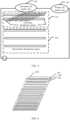
- FIG. 2A structure of the heat dissipation mechanical part in this embodiment of this application is shown in FIG. 2 .
- the heat dissipation mechanical part shown in FIG. 2includes a plurality of heat dissipation pipes that are parallel to each other and are located in a same plane, and the entire heat dissipation mechanical part is divided into a first heat dissipation region 201 and a second heat dissipation region 202.
- the first heat dissipation region 201is relatively far away from an air exhaust vent
- the second heat dissipation region 202is relatively close to the air exhaust vent
- density of heat dissipation channels in the first heat dissipation region 201is greater than density of heat dissipation channels in the second heat dissipation region 202.
- FIG. 3Another structure of the heat dissipation mechanical part in this embodiment of this application is shown in FIG. 3 .
- the heat dissipation mechanical part shown in FIG. 3includes a first heat dissipation region 301, a second heat dissipation region 302, a primary air intake vent 303, and a secondary air intake vent 304.
- Density of ventilation pipes in the first heat dissipation region 301is greater than that in the second heat dissipation region 302.
- the first heat dissipation region 301includes a primary heat dissipation pipe 3011 and a secondary heat dissipation pipe 3012.
- the primary heat dissipation pipe 3011is in a same direction as a heat dissipation pipe in the second heat dissipation region 302, and the primary heat dissipation pipe 3011 and the heat dissipation pipe in the second heat dissipation region 302 are parallel to each other.
- the secondary heat dissipation pipe 3012 and the primary heat dissipation pipe 3011are in different directions, the secondary heat dissipation pipe 3012 is connected to the secondary air intake vent 304, and the primary heat dissipation pipe 3011 and the heat dissipation pipe in the second heat dissipation region 302 are connected to the primary air intake vent 303.
- the secondary heat dissipation pipe 3012 and the primary heat dissipation pipe 3011are connected to each other. Air may enter the primary heat dissipation pipe 3011 from the primary air intake vent 303, and then flow out from the air exhaust vent. Air flows into the secondary heat dissipation pipe 3012 from the secondary air intake vent 304, and then is converged to a primary heat dissipation pipe 3011, and then flows out from the air exhaust vent.
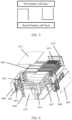
- FIG. 4Another structure of the heat dissipation mechanical part in this embodiment of this application is shown in FIG. 4 .
- the heat dissipation mechanical part shown in FIG. 4includes a primary heat dissipation pipe 401 and a secondary heat dissipation pipe 402.
- the primary heat dissipation pipe 401 and the secondary heat dissipation pipe 402are connected to each other, the primary heat dissipation pipe 401 and the secondary heat dissipation pipe 402 are perpendicular to each other, the secondary heat dissipation pipe 402 is connected to a secondary air intake vent, and the primary heat dissipation pipe 401 is connected to a primary air intake vent.
- An opening direction of the primary heat dissipation pipe 401 and an opening direction of a primary heat dissipation pipe 403are the same, and the primary heat dissipation pipe 403 and a primary heat dissipation pipe 404 are adjacent and have opposite opening directions.
- the opening directionis a cooling direction, and an open surface is closely bonded to a to-be-cooled destination battery cell layer.
- a scenario of the heat dissipation mechanical partis shown in FIG. 5 .
- the heat dissipation mechanical partis located between a first battery cell layer and a second battery cell layer.
- an opening direction of a heat dissipation mechanical part on the leftis upward, an objective is to cool the first battery cell layer.
- an objectiveis to cool the second battery cell layer.
- the opening directionmay be set based on a requirement. In this embodiment of this application, only an example in which opening directions of adjacent primary heat dissipation pipes are opposite to each other and an opening direction of the secondary heat dissipation pipe is downward is used for description.
- the battery module shown in FIG. 6includes a battery cell 601, a fastener 602, a left busbar 603, a module fan 604, a left insulated cover plate 605, a left panel 606, a right busbar 607, a right insulated cover plate 608, a right panel 609, a heat dissipation mechanical part 610, an upper cover plate 611, an air intake plate 612, a fixed sheet metal 613, a BMS control board 614, and a front panel 615.
- a structure of the heat dissipation mechanical part 610is shown in the embodiments shown in FIG. 2 to FIG. 5 .
- FIG. 7A structure of the air intake plate 612 is shown in FIG. 7 .
- the air intake plate shown in FIG. 7includes a primary air intake vent 701 and a secondary air intake vent 702.
- the secondary air intake vent 702is connected to a secondary heat dissipation channel in the heat dissipation mechanical part 610, and the primary air intake vent 701 flows into a ventilation cavity formed by using the right busbar 607, the right insulated cover plate 608, and the right panel 609.
- a structure of the right insulated cover plateis shown in FIG. 8 .
- the right insulated cover plate shown in FIG. 8includes an edge region 801 and an intermediate region 802. Density of holes included in the intermediate region 802 is higher, and density of holes included in the edge region 801 is lower.
- a structure of a convergence cavity formed by using the left panel 606, the left insulated cover plate 605, and the left busbar 603 in FIG. 6is similar to a structure of the ventilation cavity. Details are not described herein again.
- a structure of a BMS cavity formed by using the BMS control board 614 and the front panel 615 in FIG. 6is similar to the structure of the ventilation cavity and the structure of the convergence cavity. Details are not described herein again.
- FIG. 9A structure of the fastener 602 is shown in FIG. 9 .
- the fastener shown in FIG. 9includes a primary fastening strip 901, and the primary fastening strip 901 includes a plurality of parallel hole pairs. In a process of fastening the battery cell, cold air may flow through the hole.
- FIG. 10shows directions of air in the ventilation cavity and the convergence cavity.
- a ventilation gapbetween the busbar and a side panel in the ventilation cavity and the convergence cavity formed between the insulated cover plate and the side panel, so that the busbar is cooled.
- a holeis disposed on a side that is of the ventilation cavity and that is opposite to a primary air intake vent surface.
Landscapes
- Engineering & Computer Science (AREA)
- Chemical & Material Sciences (AREA)
- Chemical Kinetics & Catalysis (AREA)
- Electrochemistry (AREA)
- General Chemical & Material Sciences (AREA)
- Manufacturing & Machinery (AREA)
- Microelectronics & Electronic Packaging (AREA)
- Secondary Cells (AREA)
- Battery Mounting, Suspending (AREA)
- Physics & Mathematics (AREA)
- Thermal Sciences (AREA)
Description
- Embodiments of this application relate to the energy field, and in particular, to a battery module.
- A battery module generally includes a battery cell group, a busbar, and a battery management system (battery management system, BMS) module. When states of health (state of health, SOH) of all battery cells in the battery cell group are relatively consistent, the entire battery module may perform best performance during working, and may also have a longest life span in a relatively long time dimension. A heat dissipation system of the battery module needs to ensure that all the battery cells have as similar cooling effects as possible, so that the SOHs of all the battery cells are relatively consistent.
- A heat dissipation system of the battery module includes parallel air ducts that are evenly distributed between battery cell layers. In other words, a primary air intake duct and an air exhaust duct are respectively located on two sides, that is, a positive electrode and a negative electrode of a battery cell. A plurality of secondary air intake ducts perpendicular to the primary air intake duct and the air exhaust duct are disposed between the primary air intake duct and the air exhaust duct, the plurality of secondary air intake ducts are parallel to each other, the secondary air intake ducts have a fixed interval, the primary air intake duct, the secondary air intake ducts, and the air exhaust duct are located in a same plane, and the plane is located in the middle of surfaces of two adjacent battery cells. After air outflows from the plurality of secondary air intake ducts are converged in the air exhaust duct, the air outflows through a fan.
- However, because an amount of air in the battery module is relatively large near the fan, and is relatively small away from the fan, a relatively strong cooling effect is achieved on a battery cell near the fan, and a relatively poor cooling effect is achieved on a battery cell far away from the fan. Cooling effects of the battery cells are different, and therefore, SOHs of the battery cells are inconsistent due to different working temperature. Consequently, optimal performance and a life span of the entire battery module are reduced.
- The document
US 2006/091856 A1 shows a construction of a battery module including a unit battery aggregate having a plurality of unit batteries arranged spaced from each other. - The present invention is defined by the independent claims. Further advantageous developments are shown by the dependent claims.
- Embodiments of this application provide a battery module, so that consistency of cooling effects of battery cells can be improved, and a battery cell group has a better SOH.
- A first aspect of embodiments of this application provides a battery module.
- The battery module includes battery cells that are stacked in layers and a heat dissipation mechanical part. The heat dissipation mechanical part is located between a first battery cell layer and a second battery cell layer, and two surfaces of the heat dissipation mechanical part are respectively bonded to the first battery cell layer and the second battery cell layer.
- The heat dissipation mechanical part includes a first heat dissipation region and a second heat dissipation region, and an average distance between a heat dissipation pipe in the first heat dissipation region and a cooling medium outflow region is longer than an average distance between a heat dissipation pipe in the second heat dissipation region and the cooling medium outflow region.
- Density of heat dissipation pipes in the first heat dissipation region is greater than density of heat dissipation pipes in the second heat dissipation region.
- It may be understood that density of heat dissipation pipes in a heat dissipation region that is relatively far away from the cooling medium outflow region is greater than an area of a heat dissipation pipe in a heat dissipation region that is relatively close to the cooling medium outflow region. Therefore, a relatively strong cooling effect caused by heat dissipation pipes in relatively high density is brought to a heat dissipation region that is relatively far away from a cooling medium transport device in the cooling medium outflow region and therefore has a relatively poor cooling effect, and similar cooling effects are brought to heat dissipation regions at different distances from the cooling medium outflow region. In this way, consistency of cooling effects of battery cells is improved, so that the battery cell group has a better SOH.
- Based on the first aspect, this embodiment of this application further provides a first implementation of the first aspect:
- A first heat dissipation region that is relatively far away from the cooling medium outflow region includes a primary heat dissipation pipe and a secondary heat dissipation pipe.
- The primary heat dissipation pipe is connected to a primary cooling medium input region on a housing of the battery module, and the secondary heat dissipation pipe is connected to a secondary cooling medium input region.
- It may be understood that the secondary cooling medium input region is disposed on the housing of the battery module, and the secondary cooling medium input region is connected to the secondary heat dissipation pipe, so that a cooling medium inflow amount of the first heat dissipation region that is relatively far away from the cooling medium outflow region can be increased, and a cooling effect is improved.
- Based on the first aspect to the second implementation of the first aspect, this embodiment of this application provides a third implementation of the first aspect:
In the heat dissipation mechanical part, primary heat dissipation pipes are parallel to each other, and secondary heat dissipation pipes are parallel to each other. The primary heat dissipation pipe and the secondary heat dissipation pipe are located in a same plane, and the secondary heat dissipation pipe and the primary heat dissipation pipe are perpendicular to each other. - It may be understood that the primary heat dissipation pipe and the secondary heat dissipation pipe are perpendicular to each other. A cooling medium entering the primary heat dissipation pipe is blocked by the secondary heat dissipation pipe perpendicular to the primary heat dissipation pipe, and does not enter the secondary heat dissipation pipe. All cooling mediums in the secondary heat dissipation pipe are from a secondary cooling medium inflow region, so that the cooling medium inflow amount of the first heat dissipation region is increased.
- Based on the first aspect to the third implementation of the first aspect, this embodiment of this application provides a fourth implementation of the first aspect:
- The battery module further includes a battery cell group fastener, the battery cell group fastener is located between the housing and a surface battery cell layer, the battery cell group fastener includes two primary fastening strips, a plurality of pairs of holes are disposed on the two primary fastening strips, the plurality of pairs of holes are used to circulate the cooling medium, and a connection line of the plurality of pairs of holes is parallel to the primary heat dissipation pipe in the heat dissipation mechanical part.
- It may be understood that, after the hole is disposed on the primary fastening strip on the battery cell group fastener, the cooling medium may be circulated, and a heat dissipation function is performed, so that the heat dissipation mechanical part is prevented from being disposed on the surface battery cell layer, and space is saved.
- Based on the first aspect to the fourth implementation of the first aspect, this embodiment of this application provides a fifth implementation of the first aspect:
The battery module further includes an insulated cover plate. The insulated cover plate is located between the housing of the battery module and a positive-electrode surface of the battery cell group or is located between the housing of the battery module and a negative-electrode surface of the battery cell group, the insulated cover plate includes an intermediate region and two end regions, and density of holes disposed in the intermediate region is greater than density of holes disposed in the two end regions. - It may be understood that, after the hole is disposed on the insulated cover plate, the cooling medium may be circulated, and a heat dissipation function is performed. Therefore, a cooling medium circulating pipe is prevented from being disposed between the positive-electrode surface of the battery cell group and the housing of the battery module and between the negative-electrode surface of the battery cell group and the housing of the battery module, and space is saved.
- Based on the first aspect to the fifth implementation of the first aspect, this embodiment of this application provides a sixth implementation of the first aspect:
- The heat dissipation mechanical part is a plastic member.
- Based on the first aspect to the sixth implementation of the first aspect, this embodiment of this application provides a seventh implementation of the first aspect:
The battery cell group fastener is a sheet metal. - As can be learned from the foregoing technical solutions, embodiments of this application have the following advantages. The heat dissipation mechanical part is located between the first battery cell layer and the second battery cell layer, the two surfaces of the heat dissipation mechanical part are respectively bonded to the first battery cell layer and the second battery cell layer, the heat dissipation mechanical part includes the first heat dissipation region and the second heat dissipation region, and the density of the heat dissipation pipes in the heat dissipation region that is relatively far away from the cooling medium outflow region is greater than the density of the heat dissipation pipes in the heat dissipation region that is relatively close to the cooling medium outflow region. The density of the heat dissipation pipes in the heat dissipation region that is relatively far away from the cooling medium outflow region is greater than the area of the heat dissipation pipe in the heat dissipation region that is relatively close to the cooling medium outflow region. Therefore, a relatively strong cooling effect caused by heat dissipation pipes in relatively high density is brought to a heat dissipation region that is relatively far away from a cooling medium transport device in the cooling medium outflow region and therefore has a relatively poor cooling effect, and similar cooling effects are brought to heat dissipation regions at different distances from the cooling medium outflow region. In this way, consistency of cooling effects of battery cells is improved, so that the battery cell group has a better SOH.
FIG. 1 (A) and FIG. 1 (B) are a schematic diagram of a heat dissipation scenario of a battery module according to an embodiment of this application;FIG. 2 is a schematic diagram of a structure of a heat dissipation mechanical part according to an embodiment of this application;FIG. 3 is a schematic diagram of another structure of a heat dissipation mechanical part according to an embodiment of this application;FIG. 4 is a schematic diagram of another structure of a heat dissipation mechanical part according to an embodiment of this application;FIG. 5 is a schematic diagram of a structure of a heat dissipation pipe according to an embodiment of this application;FIG. 6 is a schematic diagram of assembly of a battery module according to an embodiment of this application;FIG. 7 is a schematic diagram of a structure of an air intake plate according to an embodiment of this application;FIG. 8 is a schematic diagram of a structure of an insulated cover plate according to an embodiment of this application;FIG. 9 is a schematic diagram of a structure of a fastener according to an embodiment of this application; andFIG. 10 is a schematic diagram of a cooling scenario of a battery module according to an embodiment of this application.- Embodiments of this application provide a battery module, to improve consistency of cooling effects of battery cells, so that a battery cell group has a better SOH.
- With the development of new energy sources, increasingly more electric energy is used, and as an apparatus that can reasonably use the electric energy, a battery is used increasingly more widely. In particular, a rechargeable battery represented by a lithium-ion battery is widely used in the field of energy storage and power.
- In actual application, to achieve an ideal use effect, the battery is used together with an electronic control unit to form a battery module for application. The battery module includes a chemical apparatus, a battery cell, an electronic control device, a busbar, a BMS control board, and the like. However, heat is generated in a process of using the chemical apparatus, the battery cell, and the electronic control apparatus. If the heat cannot be discharged in a timely manner, temperature in the battery module increases, and in this case, the battery cell and the electronic control apparatus are adversely affected in a high-temperature environment. Consequently, problems in terms of safety, stability, and a life span are caused.
- In the battery module, a life span of a battery cell group greatly differs due to a running environment. When each single battery cell in the battery cell group runs in a case in which environment is relatively consistent, not only peak performance of the battery cell group can be performed at present, but a relatively long life span can also be obtained in a long term.
- However, in current industrial application, to reduce weight and a volume of the battery module and reduce costs, the battery module mainly uses a cooling medium outflow region, and several cooling medium transport devices are disposed in the cooling medium outflow region. Consequently, battery cells in the battery cell group obtain different cooling medium circulation amounts and different cooling effects due to different distances from the cooling transport device. This greatly reduces consistency of the battery cell group, affects an SOH of the battery cell group, reduces performance of the battery cell group, and shortens a life span of the battery cell group. Therefore, a new heat dissipation structure of the battery cell group is urgently needed to improve the SOH of the battery cell group.
- A heat dissipation scenario of a battery module in an embodiment of this application is described below. Referring to
FIG. 1 (A) and FIG. 1 (B) :
This embodiment of this application may be applied to a battery module shown inFIG. 1(A) . - A
battery module 100 includes abattery cell group 101, abusbar 102, and aBMS control board 103. - The
battery cell group 101 is configured to convert chemical energy into electric energy, and heat is generated in a process of generating the electric energy. - The
busbar 102 is located on a positive-electrode side and a negative-electrode side of thebattery cell group 101, converges the electric energy generated by thebattery cell group 101 into a current, and is connected to a power-consuming apparatus or device outside thebattery module 100. - The
BMS control board 103 is configured to control a working status of each battery cell in thebattery cell group 101. When a battery cell is faulty, the BMS control board disconnects the faulty battery cell, to prevent the faulty battery cell from affecting running of the entirebattery cell group 101. - A cooling
medium inflow region 104 is a region in which a housing of the battery module communicates with the outside, and is generally obtained by disposing a hole on the housing of the battery module. A cooling medium flows into thebattery module 100 from the coolingmedium inflow region 104. - A cooling
medium outflow region 105 is a region in which the housing of the battery module communicates with the outside. Generally, a cooling medium transport device is disposed in the coolingmedium outflow region 105, to discharge the cooling medium in thebattery module 100 to the outside. - It should be noted that, in this embodiment of this application, the cooling medium may be air, or may be another cooling medium, such as inert gas or insulated liquid. This is not specifically limited herein.
- It should be noted that in this embodiment of this application, a heat dissipation structure of the battery module described below is described merely by using an example in which the cooling medium is air, the cooling medium transport device is a fan, the cooling medium inflow region is an air intake vent, and the cooling medium outflow region is an air exhaust vent.
- In this embodiment of this application, a heat dissipation scenario of the battery module is shown in
FIG. 1(B) . - The
battery cell group 101 generates heat, and thebusbar 102 and theBMS control board 103 generate heat based on a current heat effect. The heat generated by thebusbar 102 and theBMS control board 103 is discharged out of the battery module by using the coolingmedium inflow region 104, to avoid a case in which working environments of thebattery cell group 101, thebusbar 102, and theBMS control board 103 are affected because temperature increases due to the heat. In addition, dynamic change paces in a heat dissipation process further need to be adjusted to be consistent, to ensure consistency of thebattery cell group 101. - Based on the heat dissipation scenario of the battery module shown in
FIG. 1 (A) and FIG. 1 (B) , a structure of a heat dissipation mechanical part in an embodiment of this application is described below. - A structure of the heat dissipation mechanical part in this embodiment of this application is shown in
FIG. 2 . - The heat dissipation mechanical part shown in
FIG. 2 includes a plurality of heat dissipation pipes that are parallel to each other and are located in a same plane, and the entire heat dissipation mechanical part is divided into a firstheat dissipation region 201 and a secondheat dissipation region 202. - The first
heat dissipation region 201 is relatively far away from an air exhaust vent, the secondheat dissipation region 202 is relatively close to the air exhaust vent, and density of heat dissipation channels in the firstheat dissipation region 201 is greater than density of heat dissipation channels in the secondheat dissipation region 202. - Another structure of the heat dissipation mechanical part in this embodiment of this application is shown in
FIG. 3 . - The heat dissipation mechanical part shown in
FIG. 3 includes a firstheat dissipation region 301, a secondheat dissipation region 302, a primaryair intake vent 303, and a secondaryair intake vent 304. - Density of ventilation pipes in the first
heat dissipation region 301 is greater than that in the secondheat dissipation region 302. - The first
heat dissipation region 301 includes a primaryheat dissipation pipe 3011 and a secondaryheat dissipation pipe 3012. The primaryheat dissipation pipe 3011 is in a same direction as a heat dissipation pipe in the secondheat dissipation region 302, and the primaryheat dissipation pipe 3011 and the heat dissipation pipe in the secondheat dissipation region 302 are parallel to each other. The secondaryheat dissipation pipe 3012 and the primaryheat dissipation pipe 3011 are in different directions, the secondaryheat dissipation pipe 3012 is connected to the secondaryair intake vent 304, and the primaryheat dissipation pipe 3011 and the heat dissipation pipe in the secondheat dissipation region 302 are connected to the primaryair intake vent 303. - The secondary
heat dissipation pipe 3012 and the primaryheat dissipation pipe 3011 are connected to each other. Air may enter the primaryheat dissipation pipe 3011 from the primaryair intake vent 303, and then flow out from the air exhaust vent. Air flows into the secondaryheat dissipation pipe 3012 from the secondaryair intake vent 304, and then is converged to a primaryheat dissipation pipe 3011, and then flows out from the air exhaust vent. - Another structure of the heat dissipation mechanical part in this embodiment of this application is shown in
FIG. 4 . - The heat dissipation mechanical part shown in
FIG. 4 includes a primaryheat dissipation pipe 401 and a secondaryheat dissipation pipe 402. The primaryheat dissipation pipe 401 and the secondaryheat dissipation pipe 402 are connected to each other, the primaryheat dissipation pipe 401 and the secondaryheat dissipation pipe 402 are perpendicular to each other, the secondaryheat dissipation pipe 402 is connected to a secondary air intake vent, and the primaryheat dissipation pipe 401 is connected to a primary air intake vent. - It may be understood that, because the secondary
heat dissipation pipe 402 and the primaryheat dissipation pipe 401 cross and are perpendicular to each other, all cold air flowing into the secondaryheat dissipation pipe 402 is from the secondary air intake vent, and no cold air from the primary air intake vent directly enters the secondaryheat dissipation pipe 402. In this way, offloading of the cold air from the primary air intake vent can be reduced, supply from the secondary air intake vent can be increased, and an overall air intake volume can be improved. - An opening direction of the primary
heat dissipation pipe 401 and an opening direction of a primaryheat dissipation pipe 403 are the same, and the primaryheat dissipation pipe 403 and a primaryheat dissipation pipe 404 are adjacent and have opposite opening directions. The opening direction is a cooling direction, and an open surface is closely bonded to a to-be-cooled destination battery cell layer. A scenario of the heat dissipation mechanical part is shown inFIG. 5 . - The heat dissipation mechanical part is located between a first battery cell layer and a second battery cell layer. When an opening direction of a heat dissipation mechanical part on the left is upward, an objective is to cool the first battery cell layer. When the opening direction is downward, an objective is to cool the second battery cell layer. The opening direction may be set based on a requirement. In this embodiment of this application, only an example in which opening directions of adjacent primary heat dissipation pipes are opposite to each other and an opening direction of the secondary heat dissipation pipe is downward is used for description.
- With reference to the foregoing description, an embodiment of this application provides a battery module. Referring to
FIG. 6 , the battery module shown inFIG. 6 includes abattery cell 601, afastener 602, aleft busbar 603, amodule fan 604, a leftinsulated cover plate 605, aleft panel 606, aright busbar 607, a rightinsulated cover plate 608, aright panel 609, a heat dissipationmechanical part 610, anupper cover plate 611, anair intake plate 612, a fixedsheet metal 613, aBMS control board 614, and afront panel 615. - A structure of the heat dissipation
mechanical part 610 is shown in the embodiments shown inFIG. 2 to FIG. 5 . - A structure of the
air intake plate 612 is shown inFIG. 7 . - The air intake plate shown in
FIG. 7 includes a primaryair intake vent 701 and a secondaryair intake vent 702. - The secondary
air intake vent 702 is connected to a secondary heat dissipation channel in the heat dissipationmechanical part 610, and the primaryair intake vent 701 flows into a ventilation cavity formed by using theright busbar 607, the rightinsulated cover plate 608, and theright panel 609. A structure of the right insulated cover plate is shown inFIG. 8 . - The right insulated cover plate shown in
FIG. 8 includes anedge region 801 and anintermediate region 802. Density of holes included in theintermediate region 802 is higher, and density of holes included in theedge region 801 is lower. - A structure of a convergence cavity formed by using the
left panel 606, the leftinsulated cover plate 605, and theleft busbar 603 inFIG. 6 is similar to a structure of the ventilation cavity. Details are not described herein again. - A structure of a BMS cavity formed by using the
BMS control board 614 and thefront panel 615 inFIG. 6 is similar to the structure of the ventilation cavity and the structure of the convergence cavity. Details are not described herein again. - There are parallel holes on the
fastener 602. A structure of thefastener 602 is shown inFIG. 9 . - The fastener shown in
FIG. 9 includes aprimary fastening strip 901, and theprimary fastening strip 901 includes a plurality of parallel hole pairs. In a process of fastening the battery cell, cold air may flow through the hole. FIG. 10 shows directions of air in the ventilation cavity and the convergence cavity.- There is a ventilation gap between the busbar and a side panel in the ventilation cavity and the convergence cavity formed between the insulated cover plate and the side panel, so that the busbar is cooled. A hole is disposed on a side that is of the ventilation cavity and that is opposite to a primary air intake vent surface. Some air can flow into a BMS cavity formed by using a front panel 1 and a front panel 2. After the BMS cavity is cooled, the air flows into an air intake surface of a fan through a side face.
Claims (10)
- A battery module (100), comprising a heat dissipation mechanical part, whereinthe heat dissipation mechanical part is located between a first battery cell layer and a second battery cell layer, two surfaces of the heat dissipation mechanical part are respectively bonded to the first battery cell layer and the second battery cell layer, and the first battery cell layer and the second battery cell layer are two adjacent battery cell layers in a battery cell group (101);the heat dissipation mechanical part comprises a first heat dissipation region (201) and a second heat dissipation region (202);the first heat dissipation region (201) comprises M heat dissipation pipes, and an average distance between the M heat dissipation pipes and a cooling medium outflow region located on a housing is A, wherein M is a positive integer greater than or equal to 1, and A is greater than 0;the second heat dissipation region (202) comprises N heat dissipation pipes, and an average distance between the N heat dissipation pipes and the cooling medium outflow region located on the housing is B, wherein N is a positive integer greater than or equal to 1, and B is greater than 0; andwhen A is greater than B, a ratio of M to an area of the first heat dissipation region is greater than a ratio of N to an area of the second heat dissipation region,wherein a density of heat dissipation pipes in the first heat dissipation region (201) is greater than a density of heat dissipation pipes in the second heat dissipation region (202).
- The battery module (100) according to claim 1, whereinthe M heat dissipation pipes comprise W primary heat dissipation pipes and T secondary heat dissipation pipes, wherein a sum of W and T is M, W is a positive integer greater than or equal to 1, and T is a positive integer greater than or equal to 1; andthe W primary heat dissipation pipes are connected to a primary cooling medium input region, the T secondary heat dissipation pipes are connected to a secondary cooling medium input region, and the primary cooling medium input region and the secondary cooling medium input region are located in different areas on the housing.
- The battery module (100) according to claim 2, wherein
the W primary heat dissipation pipes are parallel to each other, the T secondary heat dissipation pipes are parallel to each other, and the W primary heat dissipation pipes and the T secondary heat dissipation pipes are located in a same plane. - The battery module (100) according to claim 2, wherein
the T secondary heat dissipation pipes and the W primary heat dissipation pipes are perpendicular to each other. - The battery module (100) according to any one of claims 1 to 4, comprising a battery cell group fastener, wherein
the battery cell group fastener is located between the housing and a third battery cell layer, the third battery cell layer is an uppermost battery cell layer or a lowermost battery cell layer in the battery cell group, and the battery cell group fastener is attached to a surface of the third battery cell layer. - The battery module (100) according to claim 5, wherein the battery cell group fastener comprises two primary fastening strips, C pairs of holes are disposed on the two primary fastening strips, a connection line of each pair of the C pairs of holes is parallel to the W primary heat dissipation pipes, and C is a positive integer greater than or equal to 1.
- The battery module (100) according to claim 6, comprising an insulated cover plate, wherein
the insulated cover plate is located between the housing and a positive-electrode surface and a negative-electrode surface of the electrochemical cell group, and the insulated cover plate comprises an intermediate region and two end regions, wherein the intermediate region comprises D holes, the two end regions comprise E holes, and a ratio of an area of the D holes to an area of the intermediate region is greater than a ratio of an area of the E holes to an area of the two end regions. - The battery module (100) according to claim 7, wherein the heat dissipation mechanical part is a plastic member.
- The battery module (100) according to claim 8, wherein the battery cell group fastener is a sheet metal.
- The battery module (100) according to claim 5, comprising an insulated cover plate, wherein
the insulated cover plate is located between the housing of the battery module and a negative-electrode surface of the battery cell group.
Applications Claiming Priority (1)
| Application Number | Priority Date | Filing Date | Title |
|---|---|---|---|
| CN202110322522.3ACN113206315B (en) | 2021-03-25 | 2021-03-25 | Battery module |
Publications (2)
| Publication Number | Publication Date |
|---|---|
| EP4071891A1 EP4071891A1 (en) | 2022-10-12 |
| EP4071891B1true EP4071891B1 (en) | 2023-10-18 |
Family
ID=77025689
Family Applications (1)
| Application Number | Title | Priority Date | Filing Date |
|---|---|---|---|
| EP22164316.6AActiveEP4071891B1 (en) | 2021-03-25 | 2022-03-25 | Battery module |
Country Status (3)
| Country | Link |
|---|---|
| US (1) | US12412947B2 (en) |
| EP (1) | EP4071891B1 (en) |
| CN (1) | CN113206315B (en) |
Families Citing this family (1)
| Publication number | Priority date | Publication date | Assignee | Title |
|---|---|---|---|---|
| CN113364027B (en)* | 2021-05-17 | 2023-10-10 | 华为数字能源技术有限公司 | Energy storage modules, energy storage devices and power generation systems |
Family Cites Families (13)
| Publication number | Priority date | Publication date | Assignee | Title |
|---|---|---|---|---|
| KR100658715B1 (en) | 2004-10-28 | 2006-12-15 | 삼성에스디아이 주식회사 | Battery module |
| JP5121395B2 (en) | 2007-10-31 | 2013-01-16 | 三洋電機株式会社 | Battery pack and battery pack separator |
| JP5644086B2 (en)* | 2009-10-29 | 2014-12-24 | 三洋電機株式会社 | Battery module, power supply device, and vehicle including the same |
| US9377250B2 (en)* | 2012-10-31 | 2016-06-28 | The Boeing Company | Cross-flow heat exchanger having graduated fin density |
| CN203746929U (en)* | 2013-12-29 | 2014-07-30 | 长城汽车股份有限公司 | Battery system for supplying power for hybrid vehicle |
| TWI489674B (en) | 2014-01-13 | 2015-06-21 | 新普科技股份有限公司 | Heat spreader and battery module |
| KR102274518B1 (en)* | 2017-09-29 | 2021-07-06 | 주식회사 엘지에너지솔루션 | Cooling jacket having an ununiformed flow channels for cooling an secondary battery cell and battery module including the same |
| CN210778180U (en) | 2019-08-26 | 2020-06-16 | 东莞市立宇电子有限公司 | A coil heat dissipation structure |
| CN210926220U (en)* | 2019-09-25 | 2020-07-03 | 嘉兴伏尔电子科技有限公司 | Energy storage battery PACK |
| CN211480235U (en) | 2020-01-02 | 2020-09-11 | 阳光电源股份有限公司 | Battery pack |
| CN212209703U (en)* | 2020-06-29 | 2020-12-22 | 蜂巢能源科技有限公司 | Air-cooled plates and battery modules for battery modules |
| CN112086711B (en)* | 2020-09-11 | 2022-08-12 | 湖北亿纬动力有限公司 | a battery box |
| CN112072043A (en)* | 2020-10-10 | 2020-12-11 | 湖北亿纬动力有限公司 | a battery pack |
- 2021
- 2021-03-25CNCN202110322522.3Apatent/CN113206315B/enactiveActive
- 2022
- 2022-03-24USUS17/702,968patent/US12412947B2/enactiveActive
- 2022-03-25EPEP22164316.6Apatent/EP4071891B1/enactiveActive
Also Published As
| Publication number | Publication date |
|---|---|
| US12412947B2 (en) | 2025-09-09 |
| EP4071891A1 (en) | 2022-10-12 |
| CN113206315A (en) | 2021-08-03 |
| CN113206315B (en) | 2022-12-30 |
| US20220311074A1 (en) | 2022-09-29 |
Similar Documents
| Publication | Publication Date | Title |
|---|---|---|
| US12183906B2 (en) | Battery module assembly, battery pack, and device using battery as power source | |
| CN112771345B (en) | Thermal management structure with integrated channels | |
| US10096869B2 (en) | Battery module, battery temperature managing system and vehicle comprising the same | |
| US20240283050A1 (en) | Water cooling plate assembly, water cooling system, battery, battery box, and electrical device | |
| US10622601B2 (en) | Battery module carrier, battery system and use of a modified H-beam as battery module carrier | |
| US20110206970A1 (en) | Battery module, method for fabricating the same, and temperature adjusting system | |
| KR20130086018A (en) | Battery module with compact structure and excellent heat radiation characteristics and middle or large-sized battery pack employed with the same | |
| US20230032539A1 (en) | Battery, electric apparatus, method for preparing battery, and apparatus for preparing battery | |
| CN109891666B (en) | Battery module | |
| US10892529B2 (en) | Air-cooling battery module | |
| CN115917837A (en) | Battery module and battery pack including the battery module | |
| EP4071891B1 (en) | Battery module | |
| US20230268588A1 (en) | Battery, power consumption device, and method and device for producing battery | |
| KR102803301B1 (en) | Air cooling type battery pack for electric vehicle | |
| US20250087787A1 (en) | Battery Pack Including Cooling Member and Device Including the Same | |
| CN212323043U (en) | Fuel cell, power assembly and vehicle | |
| KR20240064712A (en) | Battery and its manufacturing method and electrical device | |
| CN219066956U (en) | Battery pack and electricity utilization device | |
| US20230307740A1 (en) | Battery cell, battery, apparatus, and method and device for manufacturing battery cell | |
| WO2023141885A1 (en) | Battery, power-consuming device, method for preparing battery, and device for preparing battery | |
| CN222705604U (en) | Energy storage battery cluster | |
| CN215184207U (en) | Heat dissipation plate and battery module | |
| CN223140876U (en) | Battery packs and electrical equipment | |
| CN222562706U (en) | A fuel cell engine for unmanned aerial vehicles | |
| CN220963505U (en) | Air cooling device for battery |
Legal Events
| Date | Code | Title | Description |
|---|---|---|---|
| PUAI | Public reference made under article 153(3) epc to a published international application that has entered the european phase | Free format text:ORIGINAL CODE: 0009012 | |
| STAA | Information on the status of an ep patent application or granted ep patent | Free format text:STATUS: REQUEST FOR EXAMINATION WAS MADE | |
| 17P | Request for examination filed | Effective date:20220325 | |
| AK | Designated contracting states | Kind code of ref document:A1 Designated state(s):AL AT BE BG CH CY CZ DE DK EE ES FI FR GB GR HR HU IE IS IT LI LT LU LV MC MK MT NL NO PL PT RO RS SE SI SK SM TR | |
| GRAP | Despatch of communication of intention to grant a patent | Free format text:ORIGINAL CODE: EPIDOSNIGR1 | |
| RIC1 | Information provided on ipc code assigned before grant | Ipc:H01M 50/204 20210101ALI20230328BHEP Ipc:H01M 10/6561 20140101ALI20230328BHEP Ipc:H01M 10/6557 20140101ALI20230328BHEP Ipc:H01M 10/617 20140101ALI20230328BHEP Ipc:H01M 10/613 20140101AFI20230328BHEP | |
| STAA | Information on the status of an ep patent application or granted ep patent | Free format text:STATUS: GRANT OF PATENT IS INTENDED | |
| INTG | Intention to grant announced | Effective date:20230504 | |
| GRAS | Grant fee paid | Free format text:ORIGINAL CODE: EPIDOSNIGR3 | |
| P01 | Opt-out of the competence of the unified patent court (upc) registered | Effective date:20230727 | |
| GRAA | (expected) grant | Free format text:ORIGINAL CODE: 0009210 | |
| STAA | Information on the status of an ep patent application or granted ep patent | Free format text:STATUS: THE PATENT HAS BEEN GRANTED | |
| AK | Designated contracting states | Kind code of ref document:B1 Designated state(s):AL AT BE BG CH CY CZ DE DK EE ES FI FR GB GR HR HU IE IS IT LI LT LU LV MC MK MT NL NO PL PT RO RS SE SI SK SM TR | |
| REG | Reference to a national code | Ref country code:GB Ref legal event code:FG4D | |
| REG | Reference to a national code | Ref country code:CH Ref legal event code:EP | |
| REG | Reference to a national code | Ref country code:IE Ref legal event code:FG4D | |
| REG | Reference to a national code | Ref country code:DE Ref legal event code:R096 Ref document number:602022000698 Country of ref document:DE | |
| REG | Reference to a national code | Ref country code:LT Ref legal event code:MG9D | |
| REG | Reference to a national code | Ref country code:NL Ref legal event code:MP Effective date:20231018 | |
| REG | Reference to a national code | Ref country code:AT Ref legal event code:MK05 Ref document number:1623280 Country of ref document:AT Kind code of ref document:T Effective date:20231018 | |
| PG25 | Lapsed in a contracting state [announced via postgrant information from national office to epo] | Ref country code:NL Free format text:LAPSE BECAUSE OF FAILURE TO SUBMIT A TRANSLATION OF THE DESCRIPTION OR TO PAY THE FEE WITHIN THE PRESCRIBED TIME-LIMIT Effective date:20231018 | |
| PG25 | Lapsed in a contracting state [announced via postgrant information from national office to epo] | Ref country code:GR Free format text:LAPSE BECAUSE OF FAILURE TO SUBMIT A TRANSLATION OF THE DESCRIPTION OR TO PAY THE FEE WITHIN THE PRESCRIBED TIME-LIMIT Effective date:20240119 | |
| PG25 | Lapsed in a contracting state [announced via postgrant information from national office to epo] | Ref country code:IS Free format text:LAPSE BECAUSE OF FAILURE TO SUBMIT A TRANSLATION OF THE DESCRIPTION OR TO PAY THE FEE WITHIN THE PRESCRIBED TIME-LIMIT Effective date:20240218 | |
| PG25 | Lapsed in a contracting state [announced via postgrant information from national office to epo] | Ref country code:LT Free format text:LAPSE BECAUSE OF FAILURE TO SUBMIT A TRANSLATION OF THE DESCRIPTION OR TO PAY THE FEE WITHIN THE PRESCRIBED TIME-LIMIT Effective date:20231018 | |
| PG25 | Lapsed in a contracting state [announced via postgrant information from national office to epo] | Ref country code:AT Free format text:LAPSE BECAUSE OF FAILURE TO SUBMIT A TRANSLATION OF THE DESCRIPTION OR TO PAY THE FEE WITHIN THE PRESCRIBED TIME-LIMIT Effective date:20231018 | |
| PG25 | Lapsed in a contracting state [announced via postgrant information from national office to epo] | Ref country code:ES Free format text:LAPSE BECAUSE OF FAILURE TO SUBMIT A TRANSLATION OF THE DESCRIPTION OR TO PAY THE FEE WITHIN THE PRESCRIBED TIME-LIMIT Effective date:20231018 | |
| PG25 | Lapsed in a contracting state [announced via postgrant information from national office to epo] | Ref country code:LT Free format text:LAPSE BECAUSE OF FAILURE TO SUBMIT A TRANSLATION OF THE DESCRIPTION OR TO PAY THE FEE WITHIN THE PRESCRIBED TIME-LIMIT Effective date:20231018 Ref country code:IS Free format text:LAPSE BECAUSE OF FAILURE TO SUBMIT A TRANSLATION OF THE DESCRIPTION OR TO PAY THE FEE WITHIN THE PRESCRIBED TIME-LIMIT Effective date:20240218 Ref country code:GR Free format text:LAPSE BECAUSE OF FAILURE TO SUBMIT A TRANSLATION OF THE DESCRIPTION OR TO PAY THE FEE WITHIN THE PRESCRIBED TIME-LIMIT Effective date:20240119 Ref country code:ES Free format text:LAPSE BECAUSE OF FAILURE TO SUBMIT A TRANSLATION OF THE DESCRIPTION OR TO PAY THE FEE WITHIN THE PRESCRIBED TIME-LIMIT Effective date:20231018 Ref country code:BG Free format text:LAPSE BECAUSE OF FAILURE TO SUBMIT A TRANSLATION OF THE DESCRIPTION OR TO PAY THE FEE WITHIN THE PRESCRIBED TIME-LIMIT Effective date:20240118 Ref country code:AT Free format text:LAPSE BECAUSE OF FAILURE TO SUBMIT A TRANSLATION OF THE DESCRIPTION OR TO PAY THE FEE WITHIN THE PRESCRIBED TIME-LIMIT Effective date:20231018 Ref country code:PT Free format text:LAPSE BECAUSE OF FAILURE TO SUBMIT A TRANSLATION OF THE DESCRIPTION OR TO PAY THE FEE WITHIN THE PRESCRIBED TIME-LIMIT Effective date:20240219 | |
| PG25 | Lapsed in a contracting state [announced via postgrant information from national office to epo] | Ref country code:SE Free format text:LAPSE BECAUSE OF FAILURE TO SUBMIT A TRANSLATION OF THE DESCRIPTION OR TO PAY THE FEE WITHIN THE PRESCRIBED TIME-LIMIT Effective date:20231018 Ref country code:RS Free format text:LAPSE BECAUSE OF FAILURE TO SUBMIT A TRANSLATION OF THE DESCRIPTION OR TO PAY THE FEE WITHIN THE PRESCRIBED TIME-LIMIT Effective date:20231018 Ref country code:PL Free format text:LAPSE BECAUSE OF FAILURE TO SUBMIT A TRANSLATION OF THE DESCRIPTION OR TO PAY THE FEE WITHIN THE PRESCRIBED TIME-LIMIT Effective date:20231018 Ref country code:NO Free format text:LAPSE BECAUSE OF FAILURE TO SUBMIT A TRANSLATION OF THE DESCRIPTION OR TO PAY THE FEE WITHIN THE PRESCRIBED TIME-LIMIT Effective date:20240118 Ref country code:LV Free format text:LAPSE BECAUSE OF FAILURE TO SUBMIT A TRANSLATION OF THE DESCRIPTION OR TO PAY THE FEE WITHIN THE PRESCRIBED TIME-LIMIT Effective date:20231018 Ref country code:HR Free format text:LAPSE BECAUSE OF FAILURE TO SUBMIT A TRANSLATION OF THE DESCRIPTION OR TO PAY THE FEE WITHIN THE PRESCRIBED TIME-LIMIT Effective date:20231018 | |
| PG25 | Lapsed in a contracting state [announced via postgrant information from national office to epo] | Ref country code:DK Free format text:LAPSE BECAUSE OF FAILURE TO SUBMIT A TRANSLATION OF THE DESCRIPTION OR TO PAY THE FEE WITHIN THE PRESCRIBED TIME-LIMIT Effective date:20231018 | |
| REG | Reference to a national code | Ref country code:DE Ref legal event code:R097 Ref document number:602022000698 Country of ref document:DE | |
| PG25 | Lapsed in a contracting state [announced via postgrant information from national office to epo] | Ref country code:CZ Free format text:LAPSE BECAUSE OF FAILURE TO SUBMIT A TRANSLATION OF THE DESCRIPTION OR TO PAY THE FEE WITHIN THE PRESCRIBED TIME-LIMIT Effective date:20231018 | |
| PG25 | Lapsed in a contracting state [announced via postgrant information from national office to epo] | Ref country code:SK Free format text:LAPSE BECAUSE OF FAILURE TO SUBMIT A TRANSLATION OF THE DESCRIPTION OR TO PAY THE FEE WITHIN THE PRESCRIBED TIME-LIMIT Effective date:20231018 | |
| PG25 | Lapsed in a contracting state [announced via postgrant information from national office to epo] | Ref country code:SM Free format text:LAPSE BECAUSE OF FAILURE TO SUBMIT A TRANSLATION OF THE DESCRIPTION OR TO PAY THE FEE WITHIN THE PRESCRIBED TIME-LIMIT Effective date:20231018 Ref country code:SK Free format text:LAPSE BECAUSE OF FAILURE TO SUBMIT A TRANSLATION OF THE DESCRIPTION OR TO PAY THE FEE WITHIN THE PRESCRIBED TIME-LIMIT Effective date:20231018 Ref country code:RO Free format text:LAPSE BECAUSE OF FAILURE TO SUBMIT A TRANSLATION OF THE DESCRIPTION OR TO PAY THE FEE WITHIN THE PRESCRIBED TIME-LIMIT Effective date:20231018 Ref country code:IT Free format text:LAPSE BECAUSE OF FAILURE TO SUBMIT A TRANSLATION OF THE DESCRIPTION OR TO PAY THE FEE WITHIN THE PRESCRIBED TIME-LIMIT Effective date:20231018 Ref country code:EE Free format text:LAPSE BECAUSE OF FAILURE TO SUBMIT A TRANSLATION OF THE DESCRIPTION OR TO PAY THE FEE WITHIN THE PRESCRIBED TIME-LIMIT Effective date:20231018 Ref country code:DK Free format text:LAPSE BECAUSE OF FAILURE TO SUBMIT A TRANSLATION OF THE DESCRIPTION OR TO PAY THE FEE WITHIN THE PRESCRIBED TIME-LIMIT Effective date:20231018 Ref country code:CZ Free format text:LAPSE BECAUSE OF FAILURE TO SUBMIT A TRANSLATION OF THE DESCRIPTION OR TO PAY THE FEE WITHIN THE PRESCRIBED TIME-LIMIT Effective date:20231018 | |
| PLBE | No opposition filed within time limit | Free format text:ORIGINAL CODE: 0009261 | |
| STAA | Information on the status of an ep patent application or granted ep patent | Free format text:STATUS: NO OPPOSITION FILED WITHIN TIME LIMIT | |
| 26N | No opposition filed | Effective date:20240719 | |
| PG25 | Lapsed in a contracting state [announced via postgrant information from national office to epo] | Ref country code:SI Free format text:LAPSE BECAUSE OF FAILURE TO SUBMIT A TRANSLATION OF THE DESCRIPTION OR TO PAY THE FEE WITHIN THE PRESCRIBED TIME-LIMIT Effective date:20231018 | |
| PG25 | Lapsed in a contracting state [announced via postgrant information from national office to epo] | Ref country code:SI Free format text:LAPSE BECAUSE OF FAILURE TO SUBMIT A TRANSLATION OF THE DESCRIPTION OR TO PAY THE FEE WITHIN THE PRESCRIBED TIME-LIMIT Effective date:20231018 | |
| PG25 | Lapsed in a contracting state [announced via postgrant information from national office to epo] | Ref country code:LU Free format text:LAPSE BECAUSE OF NON-PAYMENT OF DUE FEES Effective date:20240325 | |
| PG25 | Lapsed in a contracting state [announced via postgrant information from national office to epo] | Ref country code:MC Free format text:LAPSE BECAUSE OF FAILURE TO SUBMIT A TRANSLATION OF THE DESCRIPTION OR TO PAY THE FEE WITHIN THE PRESCRIBED TIME-LIMIT Effective date:20231018 | |
| PG25 | Lapsed in a contracting state [announced via postgrant information from national office to epo] | Ref country code:MC Free format text:LAPSE BECAUSE OF FAILURE TO SUBMIT A TRANSLATION OF THE DESCRIPTION OR TO PAY THE FEE WITHIN THE PRESCRIBED TIME-LIMIT Effective date:20231018 Ref country code:LU Free format text:LAPSE BECAUSE OF NON-PAYMENT OF DUE FEES Effective date:20240325 | |
| REG | Reference to a national code | Ref country code:BE Ref legal event code:MM Effective date:20240331 | |
| PG25 | Lapsed in a contracting state [announced via postgrant information from national office to epo] | Ref country code:BE Free format text:LAPSE BECAUSE OF NON-PAYMENT OF DUE FEES Effective date:20240331 | |
| PG25 | Lapsed in a contracting state [announced via postgrant information from national office to epo] | Ref country code:IE Free format text:LAPSE BECAUSE OF NON-PAYMENT OF DUE FEES Effective date:20240325 | |
| PG25 | Lapsed in a contracting state [announced via postgrant information from national office to epo] | Ref country code:IE Free format text:LAPSE BECAUSE OF NON-PAYMENT OF DUE FEES Effective date:20240325 Ref country code:BE Free format text:LAPSE BECAUSE OF NON-PAYMENT OF DUE FEES Effective date:20240331 | |
| PGFP | Annual fee paid to national office [announced via postgrant information from national office to epo] | Ref country code:DE Payment date:20250204 Year of fee payment:4 | |
| PGFP | Annual fee paid to national office [announced via postgrant information from national office to epo] | Ref country code:FR Payment date:20250210 Year of fee payment:4 | |
| PG25 | Lapsed in a contracting state [announced via postgrant information from national office to epo] | Ref country code:CY Free format text:LAPSE BECAUSE OF FAILURE TO SUBMIT A TRANSLATION OF THE DESCRIPTION OR TO PAY THE FEE WITHIN THE PRESCRIBED TIME-LIMIT; INVALID AB INITIO Effective date:20220325 | |
| PG25 | Lapsed in a contracting state [announced via postgrant information from national office to epo] | Ref country code:FI Free format text:LAPSE BECAUSE OF FAILURE TO SUBMIT A TRANSLATION OF THE DESCRIPTION OR TO PAY THE FEE WITHIN THE PRESCRIBED TIME-LIMIT Effective date:20231019 |