EP4070996B1 - Auto panning camera mirror system including image based trailer angle detection - Google Patents
Auto panning camera mirror system including image based trailer angle detectionDownload PDFInfo
- Publication number
- EP4070996B1 EP4070996B1EP22162581.7AEP22162581AEP4070996B1EP 4070996 B1EP4070996 B1EP 4070996B1EP 22162581 AEP22162581 AEP 22162581AEP 4070996 B1EP4070996 B1EP 4070996B1
- Authority
- EP
- European Patent Office
- Prior art keywords
- view
- vehicle
- field
- fov
- trailer
- Prior art date
- Legal status (The legal status is an assumption and is not a legal conclusion. Google has not performed a legal analysis and makes no representation as to the accuracy of the status listed.)
- Active
Links
Images


Classifications
- B—PERFORMING OPERATIONS; TRANSPORTING
- B60—VEHICLES IN GENERAL
- B60R—VEHICLES, VEHICLE FITTINGS, OR VEHICLE PARTS, NOT OTHERWISE PROVIDED FOR
- B60R1/00—Optical viewing arrangements; Real-time viewing arrangements for drivers or passengers using optical image capturing systems, e.g. cameras or video systems specially adapted for use in or on vehicles
- B60R1/02—Rear-view mirror arrangements
- G—PHYSICS
- G06—COMPUTING OR CALCULATING; COUNTING
- G06T—IMAGE DATA PROCESSING OR GENERATION, IN GENERAL
- G06T7/00—Image analysis
- G06T7/60—Analysis of geometric attributes
- G—PHYSICS
- G06—COMPUTING OR CALCULATING; COUNTING
- G06T—IMAGE DATA PROCESSING OR GENERATION, IN GENERAL
- G06T7/00—Image analysis
- G06T7/70—Determining position or orientation of objects or cameras
- G06T7/73—Determining position or orientation of objects or cameras using feature-based methods
- G—PHYSICS
- G06—COMPUTING OR CALCULATING; COUNTING
- G06V—IMAGE OR VIDEO RECOGNITION OR UNDERSTANDING
- G06V10/00—Arrangements for image or video recognition or understanding
- G06V10/20—Image preprocessing
- G06V10/25—Determination of region of interest [ROI] or a volume of interest [VOI]
- G—PHYSICS
- G06—COMPUTING OR CALCULATING; COUNTING
- G06V—IMAGE OR VIDEO RECOGNITION OR UNDERSTANDING
- G06V20/00—Scenes; Scene-specific elements
- G06V20/50—Context or environment of the image
- G06V20/56—Context or environment of the image exterior to a vehicle by using sensors mounted on the vehicle
- H—ELECTRICITY
- H04—ELECTRIC COMMUNICATION TECHNIQUE
- H04N—PICTORIAL COMMUNICATION, e.g. TELEVISION
- H04N23/00—Cameras or camera modules comprising electronic image sensors; Control thereof
- H04N23/60—Control of cameras or camera modules
- H04N23/69—Control of means for changing angle of the field of view, e.g. optical zoom objectives or electronic zooming
- H—ELECTRICITY
- H04—ELECTRIC COMMUNICATION TECHNIQUE
- H04N—PICTORIAL COMMUNICATION, e.g. TELEVISION
- H04N23/00—Cameras or camera modules comprising electronic image sensors; Control thereof
- H04N23/60—Control of cameras or camera modules
- H04N23/695—Control of camera direction for changing a field of view, e.g. pan, tilt or based on tracking of objects
- H—ELECTRICITY
- H04—ELECTRIC COMMUNICATION TECHNIQUE
- H04N—PICTORIAL COMMUNICATION, e.g. TELEVISION
- H04N7/00—Television systems
- H04N7/18—Closed-circuit television [CCTV] systems, i.e. systems in which the video signal is not broadcast
- H04N7/181—Closed-circuit television [CCTV] systems, i.e. systems in which the video signal is not broadcast for receiving images from a plurality of remote sources
- B—PERFORMING OPERATIONS; TRANSPORTING
- B60—VEHICLES IN GENERAL
- B60R—VEHICLES, VEHICLE FITTINGS, OR VEHICLE PARTS, NOT OTHERWISE PROVIDED FOR
- B60R2300/00—Details of viewing arrangements using cameras and displays, specially adapted for use in a vehicle
- B60R2300/10—Details of viewing arrangements using cameras and displays, specially adapted for use in a vehicle characterised by the type of camera system used
- B60R2300/101—Details of viewing arrangements using cameras and displays, specially adapted for use in a vehicle characterised by the type of camera system used using cameras with adjustable capturing direction
- B—PERFORMING OPERATIONS; TRANSPORTING
- B60—VEHICLES IN GENERAL
- B60R—VEHICLES, VEHICLE FITTINGS, OR VEHICLE PARTS, NOT OTHERWISE PROVIDED FOR
- B60R2300/00—Details of viewing arrangements using cameras and displays, specially adapted for use in a vehicle
- B60R2300/10—Details of viewing arrangements using cameras and displays, specially adapted for use in a vehicle characterised by the type of camera system used
- B60R2300/105—Details of viewing arrangements using cameras and displays, specially adapted for use in a vehicle characterised by the type of camera system used using multiple cameras
- B—PERFORMING OPERATIONS; TRANSPORTING
- B60—VEHICLES IN GENERAL
- B60R—VEHICLES, VEHICLE FITTINGS, OR VEHICLE PARTS, NOT OTHERWISE PROVIDED FOR
- B60R2300/00—Details of viewing arrangements using cameras and displays, specially adapted for use in a vehicle
- B60R2300/20—Details of viewing arrangements using cameras and displays, specially adapted for use in a vehicle characterised by the type of display used
- B—PERFORMING OPERATIONS; TRANSPORTING
- B60—VEHICLES IN GENERAL
- B60R—VEHICLES, VEHICLE FITTINGS, OR VEHICLE PARTS, NOT OTHERWISE PROVIDED FOR
- B60R2300/00—Details of viewing arrangements using cameras and displays, specially adapted for use in a vehicle
- B60R2300/80—Details of viewing arrangements using cameras and displays, specially adapted for use in a vehicle characterised by the intended use of the viewing arrangement
- B60R2300/808—Details of viewing arrangements using cameras and displays, specially adapted for use in a vehicle characterised by the intended use of the viewing arrangement for facilitating docking to a trailer
- G—PHYSICS
- G06—COMPUTING OR CALCULATING; COUNTING
- G06T—IMAGE DATA PROCESSING OR GENERATION, IN GENERAL
- G06T2207/00—Indexing scheme for image analysis or image enhancement
- G06T2207/30—Subject of image; Context of image processing
- G06T2207/30248—Vehicle exterior or interior
- G06T2207/30252—Vehicle exterior; Vicinity of vehicle
Definitions
- This disclosurerelates to a camera mirror system (CMS) for use in a commercial truck, and in particular to a CMS having an auto-panning feature including image-based trailer angle detection.
- CMScamera mirror system
- Mirror replacement systemsand camera systems for supplementing mirror views, are utilized in commercial vehicles to enhance the ability of a vehicle operator to see a surrounding environment.
- Camera mirror systemsutilize one or more cameras to provide an enhanced field of view to a vehicle operator.
- the mirror replacement systemscover a larger field of view than a conventional mirror, or include views that are not fully obtainable via a conventional mirror.
- stationary viewssuch as those provided by a fixed mirror or a fixed field of view camera may not provide a full view of the operation and desirable information that could be presented to the operator is not presented to the operator.
- Manual panning systemswhere the operator manually adjusts a physical camera or mirror angle can require frequent stopping of the maneuver to adjust the view provided and can provide insufficient granularity to the adjustments.
- WO 2019/202317 A1discloses a system for measuring the articulation angle of a trailer pulled by a vehicle.
- the systemcomprises: a camera mounted, in use, in a fixed orientation on the vehicle so as to image the trailer; and a processing unit arranged to receive image data from the camera.
- the processing unitis configured to: - receive initial image data from the camera from multiple orientations relative to the trailer; - identify common feature points in the initial image data to compute and store a three-dimensional map; - receive further image data as the trailer is pulled by the vehicle; - identify and track feature points in the image data relative to the stored map to estimate the pose of the camera relative to the trailer; and calculate an articulation angle based on the estimated pose.
- US 2008/231701 A1discloses a vehicle towing a trailer fitted with three video cameras fitted to the rear of the vehicle and on each door mirror.
- a view from any cameracan be presented to the driver on a display.
- a predicted trailer path, calculated in a computing unit,is also presented to the driver on the display as guide lines overlaid on the camera view.
- the computing unitis also configured to calculate a hitch angle by tracking the position of a trailer-mounted marker in the camera view.
- An exemplary method for automatically panning a view for a commercial vehicleincludes analyzing a portion of a first view at a first time to determine a position of a vehicle feature within the first view, wherein the first view is a subset of a second view, estimating an expected position of the vehicle feature in the first view at a second time subsequent to the first time, defining a region of interest centered on the expected position of the vehicle feature in the second view and analyzing the region of interest to determine an exact position of the vehicle feature at the second time, determining a current trailer angle based on a position of the vehicle feature within the second view, and adjusting the first view based on the current trailer angle.
- Another example of the above described method for automatically panning a view for a commercial vehiclefurther includes adjusting the first view at the second time based on the trailer angle, thereby ensuring that at least one additional feature of the vehicle is within the first view.
- the at least one additional featureis a rear edge of the vehicle
- any of the above methods for automatically panning a view for a commercial vehicle adjusting the first viewcomprises at least one of panning the first view within the second view, enlarging the first view within the second view, and shrinking the first view within the second view.
- any of the above methods for automatically panning a view for a commercial vehicle adjusting the first viewcomprises panning the second view.
- adjusting the first view within the second viewcomprises maintaining an unchanged second view.
- Another example of any of the above methods for automatically panning a view for a commercial vehiclefurther includes continuously iterating the method, thereby generating real time trailer angle monitoring.
- the portion of the first viewis a band extending a full horizontal length of the first view and less than a full height of the first view.
- the region of interestis a portion of the band.
- the vehicle featureis at least one wheel.
- the methodis initiated in response to the vehicle initiating a reversing maneuver.
- estimating the expected position of the vehicle feature in the second view at the second timeis based partially on one of a speed of the vehicle, a steering angle of the vehicle, yaw of the trailer, pitch of the trailer, roll, and acceleration of the vehicle.
- the first viewis a class II view of a camera mirror system and the second view is a class IV view of a camera mirror system.
- a camera mirror system for a vehicleincludes a first camera having a first field of view, a controller configured to receive the first field of view and output a subset of the first field of view to a first display, the controller including an auto-panning module configured to determine a two dimensional trailer angle based on a position of at least one vehicle feature in the first field of view, convert the two dimensional trailer angle to a three dimensional real world trailer angle, and adjust the output subset of the first field of view based on the three dimensional real world trailer angle.
- the auto-panning moduledetermines the trailer angle by analyzing a portion of the first view at a first time to determine a position of a vehicle feature within the first view, determining a two dimensional angle defined between a first line passing through the feature location and a hitch point and a second line defining a vertical axis of the image, and converting the two dimensional angle into a three dimensional real world trailer angle, estimating an expected position of the vehicle feature in the first view at a second time subsequent to the first time, defining a region of interest centered on the expected position of the vehicle feature in the first view and analyzing the region of interest to determine an exact position of the vehicle feature at the second time, and determining new trailer angle at the second time based on a position of the vehicle feature within the first view.
- Another example of any of the above described camera mirror vehicle systems for a vehiclefurther includes a second camera having a second field of view, the controller being configured to receive the second field of view and output a subset of the second field of view to the first display; and the auto-panning module being configured to determine the change in trailer angle based on the position of the at least one vehicle feature in each of the first field of view and the second field of view.
- the auto-panning moduleis further configured to adjust the output subset of the first field of view based on the determined current trailer angle.
- the adjustment to the output subset of the first field of viewcomprises at least panning the subset of the first field of view.
- the first field of viewis a Class IV field of view, and wherein the subset of the first field of view is a Class II view.
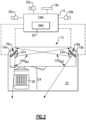
- FIG. 1A and 1BA schematic view of a commercial vehicle 10 is illustrated in Figures 1A and 1B .
- the vehicle 10includes a vehicle cab ortractor 12 for pulling a trailer 14.
- a commercial truckis contemplated in this disclosure, the invention may also be applied to other types of vehicles.
- the vehicle 10incorporates a camera mirror system (CMS) 15 ( Fig. 2 ) that has driver and passenger side camera arms 16a, 16b mounted to the outside of the vehicle cab 12.
- the camera arms 16a, 16bmay include conventional mirrors integrated with them as well, although the CMS 15 can be used to entirely replace mirrors.
- each sidecan include multiple camera arms, each arm housing one or more cameras and/or mirrors.
- Each of the camera arms 16a, 16bincludes a base that is secured to, for example, the cab 12.
- a pivoting armis supported by the base and may articulate relative thereto.
- At least one rearward facing camera 20a, 20bis arranged respectively within camera arms.
- the exterior cameras 20a, 20brespectively provide an exterior field of view FOV EX1 , FOV EX2 that each include at least one of the Class II and Class IV views ( Fig. 1B ), which are legal prescribed views in the commercial trucking industry.
- the class II view on a given side of the vehicle 10is a subset of the class IV view of the same side of the vehicle 10.
- Multiple camerasalso may be used in each camera arm 16a, 16b to provide these views, if desired.
- Each arm 16a, 16bmay also provide a housing that encloses electronics that are configured to provide various features of the CMS 15.
- First and second video displays 18a, 18bare arranged on each of the driver and passenger sides within the vehicle cab 12 on or near the A-pillars 19a, 19b to display Class II and Class IV views on its respective side of the vehicle 10, which provide rear facing side views along the vehicle 10 that are captured by the exterior cameras 20a, 20b.
- a camera housing 16c and camera 20cmay be arranged at or near the front of the vehicle 10 to provide those views ( Fig. 1B ).
- a third display 18c arranged within the cab 12 near the top center of the windshieldcan be used to display the Class V and Class VI views, which are toward the front of the vehicle 10, to the driver.
- camera housingscan be disposed at the sides and rear of the vehicle 10 to provide fields of view including some or all of the class VIII zones of the vehicle 10.
- the third display 18ccan include one or more frames displaying the class VIII views.
- additional displayscan be added near the first, second and third displays 18a, 18b, 18c and provide a display dedicated to providing a class VIII view.
- Figures 3A and 3Billustrate a vehicle 100 in the process of executing a reversing maneuver.
- the trailer 110In the initial position ( Figure 3A ) the trailer 110 has an initial angle of approximately zero degrees relative to the cab 120, meaning that it is aligned with the orientation of the cab 120. This angle can alternatively be expressed as 180 degrees relative to the cab 120.
- the trailer 110skews relative the cab 120 ( Figure 3B ) creating a trailer angle that impacts reversing maneuvers.
- the particular skew of Figure 3Bis exaggerated relative to most expected angles for the illustrative purposes.
- the rear 112 of the trailer 110is visible to the driver in at least one display through the reversing maneuver.
- a static class II viewcan result in the rear 112 of the trailer 110 extending beyond the boundaries of the class II view even when the rear 112 remains within the Class IV field of view.
- the vehicle 10, 100 illustrated hereinincludes an auto-panning feature within the camera mirror system.
- the auto-panning featureuses an image based trailer angle detection and pans the class II view within the class IV field of view in order to provide continued visualization of the rear portion 112 of the trailer 110 based on the detected trailer angle without requiring physical or mechanical adjustments to a camera angle or camera position.
- the auto-panning systemuses a real-time estimation of the trailer's angle based on iterative image analysis to continuously adjust the panning of the class II view.
- the real time trailer angle estimationis provided by an image analysis module within the CMS and can be performed entirely, or partially, based on continuous analysis of the received class II and IV images received from the cameras.
- the auto-panning systemidentifies a feature of the trailer 110 (e.g., a wheel) and tracks the position of the feature in the image. Based on the position of the feature within the image, the auto-panning system determines a two dimensional angle which is the angle between the line passing through the wheel location and the hitch point and a vertical axis of the image. The auto-panning system can then convert the two dimensional angle from the image into a three dimensional trailer angle in real space.
- wheel detectionis utilized due to the distinct shape, size and color of the wheels which allows the wheel to be distinguished from common shapes and features that may occur in the environment.
- wheelshave a uniform shape, size, and color across multiple trailer types.
- Figure 4illustrates the auto-panning process of exemplary vehicle 100.
- the auto-panning processidentifies the location of the wheels in the class II view at a known trailer 112 angle. This detection defines the initial, or previous, wheel detection position 210.
- the previous wheel detection position 210is the position within the image where the wheel was detected in the immediately prior iteration.
- an adaptive region of interest (ROI) process 220determines bounds within which the wheel is likely to be found in the new images received from the vehicle 100.
- the area inside the boundsis referred to as the region of interest.
- the initial wheel detectioncan be performed in a limited region of interest forming a band across the image. Subsequent iterations can narrow the band to a rectangle corresponding to the expected wheel position, based on the knowledge of the previous wheel position(s).
- an image processing unit 240 within the CMSanalyses only the region of interest to identify the position of the wheels within the region of interest.
- the size and shape of the region of interestcan include predefined dimensions, with the predefined dimensions representing a maximum deviation that the wheel is expected to travel in between iterations.
- the region of interestis then centered on the identified location of the wheel in the previous image, and the wheel identification is performed.
- the auto-panning featurecan be fully self-contained within the camera mirror system, and no additional sensor data is required.
- the camera mirror systemcan infer an expected direction of motion of the wheel position from a wheel motion through the images of two or more previous iterations and can determine an expected position of the wheel from the inference.
- the region of interestis centered on the expected location of the wheel, rather than being centered on the previous location of the wheel.
- the inferencecan be used to enlarge or shrink the region of interest.
- the shape and position of the region of interestcan be defined on the fly based on additional factors including the speed of the vehicle 100, a steering angle of the vehicle 100, yaw of the trailer, pitch of the trailer, roll, acceleration of the vehicle 100, or any similar sensor information that may impact an expected position of the feature being detected.
- the camera mirror systemutilizes kinematic models of vehicle reversing combined with the received sensor data to define an expected motion of the wheel through the image.
- the Auto-panning featuredetermines where the wheel is likely to be based on the expected motion and centers the adaptive region of interest around the expected wheel location.
- the CMScan include image based motion detection modules configured to detect portions of an image that are in motion relative to the originating camera and portions of the image that are not in motion.
- the CMSdefines the not-in-motion portions of the image as the "vehicle", and the in-motion portions of the image as the background.
- This definitionallows an initial region of interest to be defined as the vehicle, since it is known that the feature will always be located on the vehicle. Subsequent to the initial region of interest definition, the region of interest can be further narrowed to a subset of the detected vehicle portions in the previously described manner.
- the imageis processed using an image processing module 240 to identify the wheel (or wheels) within the region of interest.
- the analysisis limited to only the region of interest, thereby saving processing power and time and reducing potential false positives by not analyzing the majority of the image.
- the CMSuses the known position 224 of the wheel(s) in the image combined with the known position of a trailer hitch to determine the two dimensional angle of the image, as described anove.
- the relationship used to convert from the two dimensional angle determined to a real world three dimensional anglecan be determined based on experimental analysis of the specific vehicle configurations, adaptive learning processes, or any similar process.
- the positioning of the Class II view within the Class IV viewis adjusted based on the new trailer angle in order to ensure that the rear edge 112 of the trailer 110 is maintained within the Class II view.
- the adjustmentoccurs automatically, without input from the driver and is referred to as auto-panning.
- Figure 5illustrates a class IV field of view (IV) throughout the auto-panning operation discussed above.
- an initial class II view (II')is displayed in the driver's class II view.
- An initial wheel position 224'is detected within a region of interest band 226 across the view II'. Based on the initial position 224', the CMS determines an estimated wheel position and centers a narrowed region of interest 222 on the expected position of the wheels.
- the region of interest 222is analyzed via the image analysis system to determine the exact position of the wheels 224 within the region of interest 222.
- the position 224, 224' of the wheels within the imageis applied to a known relationship to determine a current trailer angle
- the CMSBased on the new trailer angle, the CMS adjusts the class II view (II, II') to maintain a view of the rear 112 of the trailer 110.
- the view (II)is shifted right, and widened within the class IV field of view.
- the process described hereiniterates approximately every 40 ms, although alternative periods between iterations could be used to similar effect. Further, the particular shifting illustrated is substantially larger than would be expected in a conventional operation as it is exaggerated for explanatory effect.
Landscapes
- Engineering & Computer Science (AREA)
- Multimedia (AREA)
- Physics & Mathematics (AREA)
- General Physics & Mathematics (AREA)
- Theoretical Computer Science (AREA)
- Signal Processing (AREA)
- Mechanical Engineering (AREA)
- Computer Vision & Pattern Recognition (AREA)
- Geometry (AREA)
- Closed-Circuit Television Systems (AREA)
- Image Analysis (AREA)
- Studio Devices (AREA)
Description
- This disclosure relates to a camera mirror system (CMS) for use in a commercial truck, and in particular to a CMS having an auto-panning feature including image-based trailer angle detection.
- Mirror replacement systems, and camera systems for supplementing mirror views, are utilized in commercial vehicles to enhance the ability of a vehicle operator to see a surrounding environment. Camera mirror systems (CMS) utilize one or more cameras to provide an enhanced field of view to a vehicle operator. In some examples, the mirror replacement systems cover a larger field of view than a conventional mirror, or include views that are not fully obtainable via a conventional mirror.
- In certain applications, such as trailer reversing maneuvers, stationary views such as those provided by a fixed mirror or a fixed field of view camera may not provide a full view of the operation and desirable information that could be presented to the operator is not presented to the operator. Manual panning systems, where the operator manually adjusts a physical camera or mirror angle can require frequent stopping of the maneuver to adjust the view provided and can provide insufficient granularity to the adjustments.
WO 2019/202317 A1 discloses a system for measuring the articulation angle of a trailer pulled by a vehicle. The system comprises: a camera mounted, in use, in a fixed orientation on the vehicle so as to image the trailer; and a processing unit arranged to receive image data from the camera. The processing unit is configured to: - receive initial image data from the camera from multiple orientations relative to the trailer; - identify common feature points in the initial image data to compute and store a three-dimensional map; - receive further image data as the trailer is pulled by the vehicle; - identify and track feature points in the image data relative to the stored map to estimate the pose of the camera relative to the trailer; and calculate an articulation angle based on the estimated pose.US 2008/231701 A1 discloses a vehicle towing a trailer fitted with three video cameras fitted to the rear of the vehicle and on each door mirror. A view from any camera can be presented to the driver on a display. A predicted trailer path, calculated in a computing unit, is also presented to the driver on the display as guide lines overlaid on the camera view. The computing unit is also configured to calculate a hitch angle by tracking the position of a trailer-mounted marker in the camera view.- An exemplary method for automatically panning a view for a commercial vehicle includes analyzing a portion of a first view at a first time to determine a position of a vehicle feature within the first view, wherein the first view is a subset of a second view, estimating an expected position of the vehicle feature in the first view at a second time subsequent to the first time, defining a region of interest centered on the expected position of the vehicle feature in the second view and analyzing the region of interest to determine an exact position of the vehicle feature at the second time, determining a current trailer angle based on a position of the vehicle feature within the second view, and adjusting the first view based on the current trailer angle.
- Another example of the above described method for automatically panning a view for a commercial vehicle further includes adjusting the first view at the second time based on the trailer angle, thereby ensuring that at least one additional feature of the vehicle is within the first view.
- In another example of any of the above methods for automatically panning a view for a commercial vehicle the at least one additional feature is a rear edge of the vehicle
- In another example of any of the above methods for automatically panning a view for a commercial vehicle adjusting the first view comprises at least one of panning the first view within the second view, enlarging the first view within the second view, and shrinking the first view within the second view.
- In another example of any of the above methods for automatically panning a view for a commercial vehicle adjusting the first view comprises panning the second view.
- In another example of any of the above methods for automatically panning a view for a commercial vehicle adjusting the first view within the second view comprises maintaining an unchanged second view.
- Another example of any of the above methods for automatically panning a view for a commercial vehicle further includes continuously iterating the method, thereby generating real time trailer angle monitoring.
- In another example of any of the above methods for automatically panning a view for a commercial vehicle the portion of the first view is a band extending a full horizontal length of the first view and less than a full height of the first view.
- In another example of any of the above methods for automatically panning a view for a commercial vehicle the region of interest is a portion of the band.
- In another example of any of the above methods for automatically panning a view for a commercial vehicle the vehicle feature is at least one wheel.
- In another example of any of the above methods for automatically panning a view for a commercial vehicle the method is initiated in response to the vehicle initiating a reversing maneuver.
- In another example of any of the above methods for automatically panning a view for a commercial vehicle estimating the expected position of the vehicle feature in the first view at the second time is based solely on the position of the vehicle feature within the second view determined by previous iterations of the method.
- In another example of any of the above methods for automatically panning a view for a commercial vehicle estimating the expected position of the vehicle feature in the second view at the second time is based partially on one of a speed of the vehicle, a steering angle of the vehicle, yaw of the trailer, pitch of the trailer, roll, and acceleration of the vehicle.
- In another example of any of the above methods for automatically panning a view for a commercial vehicle the first view is a class II view of a camera mirror system and the second view is a class IV view of a camera mirror system.
- In one exemplary embodiment a camera mirror system for a vehicle includes a first camera having a first field of view, a controller configured to receive the first field of view and output a subset of the first field of view to a first display, the controller including an auto-panning module configured to determine a two dimensional trailer angle based on a position of at least one vehicle feature in the first field of view, convert the two dimensional trailer angle to a three dimensional real world trailer angle, and adjust the output subset of the first field of view based on the three dimensional real world trailer angle.
- In another example of the above described camera mirror system for a vehicle the auto-panning module determines the trailer angle by analyzing a portion of the first view at a first time to determine a position of a vehicle feature within the first view, determining a two dimensional angle defined between a first line passing through the feature location and a hitch point and a second line defining a vertical axis of the image, and converting the two dimensional angle into a three dimensional real world trailer angle, estimating an expected position of the vehicle feature in the first view at a second time subsequent to the first time, defining a region of interest centered on the expected position of the vehicle feature in the first view and analyzing the region of interest to determine an exact position of the vehicle feature at the second time, and determining new trailer angle at the second time based on a position of the vehicle feature within the first view.
- Another example of any of the above described camera mirror vehicle systems for a vehicle further includes a second camera having a second field of view, the controller being configured to receive the second field of view and output a subset of the second field of view to the first display; and the auto-panning module being configured to determine the change in trailer angle based on the position of the at least one vehicle feature in each of the first field of view and the second field of view.
- In another example of any of the above described camera mirror vehicle systems for a vehicle the auto-panning module is further configured to adjust the output subset of the first field of view based on the determined current trailer angle.
- In another example of any of the above described camera mirror vehicle systems for a vehicle the adjustment to the output subset of the first field of view comprises at least panning the subset of the first field of view.
- In another example of any of the above described camera mirror vehicle systems for a vehicle the first field of view is a Class IV field of view, and wherein the subset of the first field of view is a Class II view.
- These and other features of the present invention can be best understood from the following specification and drawings, the following of which is a brief description.
- The disclosure can be further understood by reference to the following detailed description when considered in connection with the accompanying drawings wherein:
Figure 1A is a schematic front view of a commercial truck with a camera mirror system (CMS) used to provide at least Class II and Class IV views.Figure 1B is a schematic top elevational view of a commercial truck with a camera mirror system providing Class II, Class IV, Class V and Class VI views.Figure 2 is a schematic top perspective view of an vehicle cabin including displays and interior cameras.Figure 3A illustrates a vehicle at the initiation of a reverse maneuver, with no trailer angle.Figure 3B illustrates the vehicle mid reversing maneuver, with a high trailer angle.Figure 4 illustrates an image-based process for automatically panning a display during a reversing maneuver.Figure 5 illustrates an exemplary class IV field of view.- The embodiments, examples and alternatives of the preceding paragraphs, the claims, or the following description and drawings, including any of their various aspects or respective individual features, may be taken independently or in any combination. Features described in connection with one embodiment are applicable to all embodiments, unless such features are incompatible.
- A schematic view of a
commercial vehicle 10 is illustrated inFigures 1A and1B . Thevehicle 10 includes avehicle cab ortractor 12 for pulling atrailer 14. Although a commercial truck is contemplated in this disclosure, the invention may also be applied to other types of vehicles. Thevehicle 10 incorporates a camera mirror system (CMS) 15 (Fig. 2 ) that has driver and passengerside camera arms vehicle cab 12. If desired, thecamera arms CMS 15 can be used to entirely replace mirrors. In additional examples, each side can include multiple camera arms, each arm housing one or more cameras and/or mirrors. - Each of the
camera arms cab 12. A pivoting arm is supported by the base and may articulate relative thereto. At least one rearward facingcamera exterior cameras Fig. 1B ), which are legal prescribed views in the commercial trucking industry. The class II view on a given side of thevehicle 10 is a subset of the class IV view of the same side of thevehicle 10. Multiple cameras also may be used in eachcamera arm arm CMS 15. - First and second video displays 18a, 18b are arranged on each of the driver and passenger sides within the
vehicle cab 12 on or near the A-pillars 19a, 19b to display Class II and Class IV views on its respective side of thevehicle 10, which provide rear facing side views along thevehicle 10 that are captured by theexterior cameras - If video of Class V and Class VI views are also desired, a
camera housing 16c andcamera 20c may be arranged at or near the front of thevehicle 10 to provide those views (Fig. 1B ). Athird display 18c arranged within thecab 12 near the top center of the windshield can be used to display the Class V and Class VI views, which are toward the front of thevehicle 10, to the driver. - If video of class VIII views is desired, camera housings can be disposed at the sides and rear of the
vehicle 10 to provide fields of view including some or all of the class VIII zones of thevehicle 10. In such examples, thethird display 18c can include one or more frames displaying the class VIII views. Alternatively, additional displays can be added near the first, second andthird displays - With continued reference to
Figures 1A ,1B and2 Figures 3A and 3B illustrate avehicle 100 in the process of executing a reversing maneuver. In the initial position (Figure 3A ) thetrailer 110 has an initial angle of approximately zero degrees relative to thecab 120, meaning that it is aligned with the orientation of thecab 120. This angle can alternatively be expressed as 180 degrees relative to thecab 120. During the process of reversing, and particularly when reversing through a turn, thetrailer 110 skews relative the cab 120 (Figure 3B ) creating a trailer angle that impacts reversing maneuvers. The particular skew ofFigure 3B is exaggerated relative to most expected angles for the illustrative purposes. - In order to assist the driver in making the reversing maneuver, it is beneficial to ensure that the rear 112 of the
trailer 110 is visible to the driver in at least one display through the reversing maneuver. In some particular examples, it is desirable to not only include the rear 112 of thetrailer 110, but also to center the class II view on the rear 112 of thetrailer 110. However, as illustrated inFigure 3B , a static class II view can result in the rear 112 of thetrailer 110 extending beyond the boundaries of the class II view even when the rear 112 remains within the Class IV field of view. In order to prevent loss of view of the rear 112 of thetrailer 110 in the class II view, or to maintain centering of the class II view on the rear 112 of thetrailer 110, thevehicle rear portion 112 of thetrailer 110 based on the detected trailer angle without requiring physical or mechanical adjustments to a camera angle or camera position. In order to provide the correct panning amount, the auto-panning system uses a real-time estimation of the trailer's angle based on iterative image analysis to continuously adjust the panning of the class II view. The real time trailer angle estimation is provided by an image analysis module within the CMS and can be performed entirely, or partially, based on continuous analysis of the received class II and IV images received from the cameras. - In order to accurately estimate the trailer angle, the auto-panning system identifies a feature of the trailer 110 (e.g., a wheel) and tracks the position of the feature in the image. Based on the position of the feature within the image, the auto-panning system determines a two dimensional angle which is the angle between the line passing through the wheel location and the hitch point and a vertical axis of the image. The auto-panning system can then convert the two dimensional angle from the image into a three dimensional trailer angle in real space. In the example described herein, wheel detection is utilized due to the distinct shape, size and color of the wheels which allows the wheel to be distinguished from common shapes and features that may occur in the environment. In addition, wheels have a uniform shape, size, and color across multiple trailer types. While discussed within the context of a wheel detection, it is appreciated that alternative trailer features could be detected and utilized in the same manner and the process is not limited to wheel-based detection. Analyzing the full field of view in the class IV view to monitor the
trailer position 112 is resource intensive and can result in delays in auto-panning or sub-optimal reversing operations due to the amount of data contained in each image. - With continued reference to
Figures 1-3B ,Figure 4 illustrates the auto-panning process ofexemplary vehicle 100. Initially the auto-panning process identifies the location of the wheels in the class II view at a knowntrailer 112 angle. This detection defines the initial, or previous,wheel detection position 210. In iterations subsequent to the initial iteration, the previouswheel detection position 210 is the position within the image where the wheel was detected in the immediately prior iteration. - Once the previous wheel location within the class II/Class IV image is received, an adaptive region of interest (ROI)
process 220 determines bounds within which the wheel is likely to be found in the new images received from thevehicle 100. The area inside the bounds is referred to as the region of interest. The initial wheel detection can be performed in a limited region of interest forming a band across the image. Subsequent iterations can narrow the band to a rectangle corresponding to the expected wheel position, based on the knowledge of the previous wheel position(s). Once the region of interest is established within the received image, animage processing unit 240 within the CMS analyses only the region of interest to identify the position of the wheels within the region of interest. - In some examples, the size and shape of the region of interest can include predefined dimensions, with the predefined dimensions representing a maximum deviation that the wheel is expected to travel in between iterations. The region of interest is then centered on the identified location of the wheel in the previous image, and the wheel identification is performed. In these examples the auto-panning feature can be fully self-contained within the camera mirror system, and no additional sensor data is required. In one modification to the fully self-contained auto-panning system, the camera mirror system can infer an expected direction of motion of the wheel position from a wheel motion through the images of two or more previous iterations and can determine an expected position of the wheel from the inference. In this case, the region of interest is centered on the expected location of the wheel, rather than being centered on the previous location of the wheel. In further implementations, the inference can be used to enlarge or shrink the region of interest.
- In other examples, the shape and position of the region of interest can be defined on the fly based on additional factors including the speed of the
vehicle 100, a steering angle of thevehicle 100, yaw of the trailer, pitch of the trailer, roll, acceleration of thevehicle 100, or any similar sensor information that may impact an expected position of the feature being detected. In this example, the camera mirror system utilizes kinematic models of vehicle reversing combined with the received sensor data to define an expected motion of the wheel through the image. The Auto-panning feature determines where the wheel is likely to be based on the expected motion and centers the adaptive region of interest around the expected wheel location. - In once specific alternate example, the CMS can include image based motion detection modules configured to detect portions of an image that are in motion relative to the originating camera and portions of the image that are not in motion. In such a system, the CMS defines the not-in-motion portions of the image as the "vehicle", and the in-motion portions of the image as the background. This definition allows an initial region of interest to be defined as the vehicle, since it is known that the feature will always be located on the vehicle. Subsequent to the initial region of interest definition, the region of interest can be further narrowed to a subset of the detected vehicle portions in the previously described manner.
- Once the size and positioning of the region of interest is determined, the image is processed using an
image processing module 240 to identify the wheel (or wheels) within the region of interest. The analysis is limited to only the region of interest, thereby saving processing power and time and reducing potential false positives by not analyzing the majority of the image. - Once the
position 224 of the wheel(s) in the region ofinterest 222 is determined using theimage processing module 240, the CMS uses the knownposition 224 of the wheel(s) in the image combined with the known position of a trailer hitch to determine the two dimensional angle of the image, as described anove. The relationship used to convert from the two dimensional angle determined to a real world three dimensional angle can be determined based on experimental analysis of the specific vehicle configurations, adaptive learning processes, or any similar process. - Once the new trailer angle has been estimated, the positioning of the Class II view within the Class IV view is adjusted based on the new trailer angle in order to ensure that the
rear edge 112 of thetrailer 110 is maintained within the Class II view. The adjustment occurs automatically, without input from the driver and is referred to as auto-panning. - With continued reference to
Figures 1-4 ,Figure 5 illustrates a class IV field of view (IV) throughout the auto-panning operation discussed above. In an initial portion of the reversing maneuver, an initial class II view (II') is displayed in the driver's class II view. An initial wheel position 224' is detected within a region ofinterest band 226 across the view II'. Based on the initial position 224', the CMS determines an estimated wheel position and centers a narrowed region ofinterest 222 on the expected position of the wheels. - The region of
interest 222 is analyzed via the image analysis system to determine the exact position of thewheels 224 within the region ofinterest 222. Theposition 224, 224' of the wheels within the image is applied to a known relationship to determine a current trailer angle - Based on the new trailer angle, the CMS adjusts the class II view (II, II') to maintain a view of the rear 112 of the
trailer 110. In the illustrated example, the view (II) is shifted right, and widened within the class IV field of view. - In some examples, the process described herein iterates approximately every 40 ms, although alternative periods between iterations could be used to similar effect. Further, the particular shifting illustrated is substantially larger than would be expected in a conventional operation as it is exaggerated for explanatory effect.
- Although an example embodiment has been disclosed, a worker of ordinary skill in this art would recognize that certain modifications would come within the scope of the claims. For that reason, the following claims should be studied to determine their true scope and content. The scope of protection for the invention shall be determined by the appended claims. Nevertheless, the description and drawings shall be used to interpret the claims.
Claims (15)
- A method for automatically panning a view for a commercial vehicle (100) comprising:analyzing a portion of a first view at a first time to determine a position of a vehicle feature within the first view, wherein the first view is a subset of a second view;estimating an expected position of the vehicle feature in the first view at a second time subsequent to the first time;defining a region of interest centered on the expected position of the vehicle feature in the second view and analyzing the region of interest to determine an exact position of the vehicle feature at the second time;determining a current trailer angle based on a position of the vehicle feature within the second view; andadjusting the first view based on the current trailer angle.
- The method of claim 1, further comprising adjusting the first view at the second time based on the trailer angle, thereby ensuring that at least one additional feature of the vehicle (100) is within the first view, optionally wherein the at least one additional feature is a rear edge of the vehicle (100).
- The method of claim 2, wherein adjusting the first view comprises at least one of panning the first view within the second view, enlarging the first view within the second view, and shrinking the first view within the second view, optionally wherein adjusting the first view comprises panning the second view.
- The method of claim 2 or 3, wherein adjusting the first view within the second view comprises maintaining an unchanged second view.
- The method of any preceding claim, further comprising continuously iterating the method, thereby generating real time trailer angle monitoring.
- The method of any preceding claim, wherein the portion of the first view is a band extending a full horizontal length of the first view and less than a full height of the first view, optionally wherein the region of interest is a portion of the band.
- The method of any preceding claim, wherein the vehicle feature is at least one wheel (224).
- The method of any preceding claim, wherein the method is initiated in response to the vehicle (100) initiating a reversing maneuver.
- The method of any preceding claim, wherein estimating the expected position of the vehicle feature in the first view at the second time is based solely on the position of the vehicle feature within the second view determined by previous iterations of the method.
- The method of any preceding claim, wherein estimating the expected position of the vehicle feature in the second view at the second time is based partially on one of a speed of the vehicle (100), a steering angle of the vehicle (100), yaw of a trailer (110), pitch of the trailer (110), roll, and acceleration of the vehicle (100).
- The method of any preceding claim, wherein the first view is a class II view of a camera mirror system (15) and the second view is a class IV view of a camera mirror system (15).
- A camera mirror system (15) for a vehicle (10) comprising:a first camera (20a) having a first field of view (FOVEX1);a controller configured to receive the first field of view (FOVEX1) and output a subset of the first field of view (FOVEX1) to a first display (18a); andthe controller including an auto-panning module configured to determine a two dimensional trailer angle based on a position of at least one vehicle feature in the first field of view (FOVEX1), convert the two dimensional trailer angle to a three dimensional real world trailer angle, and adjust the output subset of the first field of view (FOVEX1) based on the three dimensional real world trailer angle.
- The camera mirror system (15) of claim 12, wherein the auto-panning module determines the trailer angle by analyzing a portion of the first view at a first time to determine a position of a vehicle feature within the first view, determining a two dimensional angle defined between a first line passing through the feature location and a hitch point and a second line defining a vertical axis of the image, and converting the two dimensional angle into a three dimensional real world trailer angle, estimating an expected position of the vehicle feature in the first view at a second time subsequent to the first time, defining a region of interest centered on the expected position of the vehicle feature in the first view and analyzing the region of interest to determine an exact position of the vehicle feature at the second time, and determining new trailer angle at the second time based on a position of the vehicle feature within the first view.
- The camera mirror system (15) of claim 12 or 13, further comprising a second camera (20b) having a second field of view (FOVEX2), the controller being configured to receive the second field of view (FOVEX2) and output a subset of the second field of view (FOVEX2) to the first display (18a); and the auto-panning module being configured to determine the change in trailer angle based on the position of the at least one vehicle feature in each of the first field of view (FOVEX1) and the second field of view (FOVEX2).
- The camera mirror system (15) of any one of claims 12 to 14, whereinthe auto-panning module is further configured to adjust the output subset of the first field of view (FOVEX1) based on the determined current trailer angle, and/orthe adjustment to the output subset of the first field of view (FOVEX1) comprises at least panning the subset of the first field of view (FOVEX1).
Applications Claiming Priority (1)
| Application Number | Priority Date | Filing Date | Title |
|---|---|---|---|
| US17/222,253US11890988B2 (en) | 2021-04-05 | 2021-04-05 | Auto panning camera mirror system including image based trailer angle detection |
Publications (2)
| Publication Number | Publication Date |
|---|---|
| EP4070996A1 EP4070996A1 (en) | 2022-10-12 |
| EP4070996B1true EP4070996B1 (en) | 2024-05-15 |
Family
ID=80785190
Family Applications (1)
| Application Number | Title | Priority Date | Filing Date |
|---|---|---|---|
| EP22162581.7AActiveEP4070996B1 (en) | 2021-04-05 | 2022-03-16 | Auto panning camera mirror system including image based trailer angle detection |
Country Status (4)
| Country | Link |
|---|---|
| US (2) | US11890988B2 (en) |
| EP (1) | EP4070996B1 (en) |
| CN (1) | CN115195604A (en) |
| BR (1) | BR102022006278A2 (en) |
Families Citing this family (5)
| Publication number | Priority date | Publication date | Assignee | Title |
|---|---|---|---|---|
| WO2019106398A1 (en)* | 2017-11-29 | 2019-06-06 | Volvo Truck Corporation | A camera assembly for an industrial vehicle cab |
| US11780371B2 (en)* | 2021-06-10 | 2023-10-10 | Stoneridge, Inc. | Auto panning camera mirror system including weighted trailer angle estimation |
| EP4190637B1 (en)* | 2021-12-02 | 2025-08-06 | Motherson Innovations Company Ltd. | Vehicle tracking for a camera wing system |
| WO2024107690A1 (en)* | 2022-11-18 | 2024-05-23 | Stoneridge, Inc. | Trailer backup trajectory overlay using trailer camera display system |
| CN120500423A (en)* | 2022-12-07 | 2025-08-15 | 石通瑞吉电子公司 | Trailer Camera Display System |
Family Cites Families (12)
| Publication number | Priority date | Publication date | Assignee | Title |
|---|---|---|---|---|
| GB2447672B (en) | 2007-03-21 | 2011-12-14 | Ford Global Tech Llc | Vehicle manoeuvring aids |
| US9085261B2 (en) | 2011-01-26 | 2015-07-21 | Magna Electronics Inc. | Rear vision system with trailer angle detection |
| DE102011104256A1 (en) | 2011-06-15 | 2012-07-26 | Audi Ag | Bend angle sensor for driver assistance system of motor car formed for drawing trailer with drawbar, has computing unit comparing image features with current image to determine bend angle, where features are stored in calibration phase |
| EP2721593B1 (en)* | 2011-06-17 | 2017-04-05 | Leddartech Inc. | System and method for traffic side detection and characterization |
| DE102011113191B4 (en) | 2011-09-10 | 2022-10-06 | Volkswagen Aktiengesellschaft | Method and device for determining an articulation angle between a vehicle and a trailer |
| US9446713B2 (en)* | 2012-09-26 | 2016-09-20 | Magna Electronics Inc. | Trailer angle detection system |
| WO2016176487A1 (en)* | 2015-04-28 | 2016-11-03 | Henri Johnson | Systems to track a moving sports object |
| US10011228B2 (en) | 2015-12-17 | 2018-07-03 | Ford Global Technologies, Llc | Hitch angle detection for trailer backup assist system using multiple imaging devices |
| US10046800B2 (en) | 2016-08-10 | 2018-08-14 | Ford Global Technologies, Llc | Trailer wheel targetless trailer angle detection |
| DE102017130566B4 (en)* | 2017-12-19 | 2021-07-22 | Mekra Lang Gmbh & Co. Kg | Vision system for capturing a vehicle environment and a mirror replacement system for a vehicle with a vision system |
| GB201806279D0 (en) | 2018-04-17 | 2018-05-30 | Cambridge Entpr Ltd | Method and system of articulation angle measurement |
| US20200317127A1 (en)* | 2019-04-03 | 2020-10-08 | GM Global Technology Operations LLC | Method and apparatus for articulating mirrors for trailering in a motor vehicle |
- 2021
- 2021-04-05USUS17/222,253patent/US11890988B2/enactiveActive
- 2022
- 2022-03-16EPEP22162581.7Apatent/EP4070996B1/enactiveActive
- 2022-03-31BRBR102022006278-1Apatent/BR102022006278A2/ennot_activeApplication Discontinuation
- 2022-04-02CNCN202210351308.5Apatent/CN115195604A/enactivePending
- 2023
- 2023-11-22USUS18/517,450patent/US12344165B2/enactiveActive
Also Published As
| Publication number | Publication date |
|---|---|
| CN115195604A (en) | 2022-10-18 |
| US11890988B2 (en) | 2024-02-06 |
| US12344165B2 (en) | 2025-07-01 |
| BR102022006278A2 (en) | 2022-10-11 |
| EP4070996A1 (en) | 2022-10-12 |
| US20220314881A1 (en) | 2022-10-06 |
| US20240083356A1 (en) | 2024-03-14 |
Similar Documents
| Publication | Publication Date | Title |
|---|---|---|
| EP4070996B1 (en) | Auto panning camera mirror system including image based trailer angle detection | |
| US20030091228A1 (en) | Image recognition apparatus | |
| US11498617B2 (en) | Vehicle control method and vehicle control device | |
| EP1718062B1 (en) | Operation support device | |
| EP4170590A1 (en) | Trailer end tracking in a commercial vehicle camera mirror system | |
| US11872942B2 (en) | Dynamic longitudinal and lateral adjustment of awareness lines for commercial vehicle camera mirror system | |
| CN108422932A (en) | driving assistance system, method and vehicle | |
| EP4290876A1 (en) | Auto panning camera monitoring system including image based trailer angle detection | |
| KR101849326B1 (en) | Camera system for vehicle | |
| US20240087159A1 (en) | Camera monitor system for commercial vehicles including wheel position estimation | |
| KR101663292B1 (en) | Method and apparatus for parking assist system | |
| WO2018037032A1 (en) | A vehicle camera system | |
| EP4347314B1 (en) | Camera monitoring system display including parallax manipulation | |
| US12257953B2 (en) | Trailer striking area prediction using camera monitoring system | |
| CN119895469A (en) | Camera monitoring system including trailer presence detection using optical flow | |
| WO2024107690A1 (en) | Trailer backup trajectory overlay using trailer camera display system | |
| JP2025532771A (en) | Camera Surveillance System Including Trailer Presence Detection Using Optical Flow | |
| CN119821284A (en) | Driving safety display method, device, equipment, medium and program product |
Legal Events
| Date | Code | Title | Description |
|---|---|---|---|
| PUAI | Public reference made under article 153(3) epc to a published international application that has entered the european phase | Free format text:ORIGINAL CODE: 0009012 | |
| STAA | Information on the status of an ep patent application or granted ep patent | Free format text:STATUS: THE APPLICATION HAS BEEN PUBLISHED | |
| AK | Designated contracting states | Kind code of ref document:A1 Designated state(s):AL AT BE BG CH CY CZ DE DK EE ES FI FR GB GR HR HU IE IS IT LI LT LU LV MC MK MT NL NO PL PT RO RS SE SI SK SM TR | |
| STAA | Information on the status of an ep patent application or granted ep patent | Free format text:STATUS: REQUEST FOR EXAMINATION WAS MADE | |
| 17P | Request for examination filed | Effective date:20230329 | |
| RBV | Designated contracting states (corrected) | Designated state(s):AL AT BE BG CH CY CZ DE DK EE ES FI FR GB GR HR HU IE IS IT LI LT LU LV MC MK MT NL NO PL PT RO RS SE SI SK SM TR | |
| P01 | Opt-out of the competence of the unified patent court (upc) registered | Effective date:20230529 | |
| GRAP | Despatch of communication of intention to grant a patent | Free format text:ORIGINAL CODE: EPIDOSNIGR1 | |
| STAA | Information on the status of an ep patent application or granted ep patent | Free format text:STATUS: GRANT OF PATENT IS INTENDED | |
| INTG | Intention to grant announced | Effective date:20231206 | |
| GRAS | Grant fee paid | Free format text:ORIGINAL CODE: EPIDOSNIGR3 | |
| GRAA | (expected) grant | Free format text:ORIGINAL CODE: 0009210 | |
| STAA | Information on the status of an ep patent application or granted ep patent | Free format text:STATUS: THE PATENT HAS BEEN GRANTED | |
| AK | Designated contracting states | Kind code of ref document:B1 Designated state(s):AL AT BE BG CH CY CZ DE DK EE ES FI FR GB GR HR HU IE IS IT LI LT LU LV MC MK MT NL NO PL PT RO RS SE SI SK SM TR | |
| REG | Reference to a national code | Ref country code:CH Ref legal event code:EP | |
| REG | Reference to a national code | Ref country code:DE Ref legal event code:R096 Ref document number:602022003422 Country of ref document:DE | |
| REG | Reference to a national code | Ref country code:IE Ref legal event code:FG4D | |
| REG | Reference to a national code | Ref country code:SE Ref legal event code:TRGR | |
| REG | Reference to a national code | Ref country code:LT Ref legal event code:MG9D | |
| REG | Reference to a national code | Ref country code:NL Ref legal event code:MP Effective date:20240515 | |
| PG25 | Lapsed in a contracting state [announced via postgrant information from national office to epo] | Ref country code:IS Free format text:LAPSE BECAUSE OF FAILURE TO SUBMIT A TRANSLATION OF THE DESCRIPTION OR TO PAY THE FEE WITHIN THE PRESCRIBED TIME-LIMIT Effective date:20240915 | |
| PG25 | Lapsed in a contracting state [announced via postgrant information from national office to epo] | Ref country code:BG Free format text:LAPSE BECAUSE OF FAILURE TO SUBMIT A TRANSLATION OF THE DESCRIPTION OR TO PAY THE FEE WITHIN THE PRESCRIBED TIME-LIMIT Effective date:20240515 | |
| PG25 | Lapsed in a contracting state [announced via postgrant information from national office to epo] | Ref country code:FI Free format text:LAPSE BECAUSE OF FAILURE TO SUBMIT A TRANSLATION OF THE DESCRIPTION OR TO PAY THE FEE WITHIN THE PRESCRIBED TIME-LIMIT Effective date:20240515 Ref country code:HR Free format text:LAPSE BECAUSE OF FAILURE TO SUBMIT A TRANSLATION OF THE DESCRIPTION OR TO PAY THE FEE WITHIN THE PRESCRIBED TIME-LIMIT Effective date:20240515 | |
| PG25 | Lapsed in a contracting state [announced via postgrant information from national office to epo] | Ref country code:GR Free format text:LAPSE BECAUSE OF FAILURE TO SUBMIT A TRANSLATION OF THE DESCRIPTION OR TO PAY THE FEE WITHIN THE PRESCRIBED TIME-LIMIT Effective date:20240816 | |
| PG25 | Lapsed in a contracting state [announced via postgrant information from national office to epo] | Ref country code:PT Free format text:LAPSE BECAUSE OF FAILURE TO SUBMIT A TRANSLATION OF THE DESCRIPTION OR TO PAY THE FEE WITHIN THE PRESCRIBED TIME-LIMIT Effective date:20240916 | |
| REG | Reference to a national code | Ref country code:AT Ref legal event code:MK05 Ref document number:1686697 Country of ref document:AT Kind code of ref document:T Effective date:20240515 | |
| PG25 | Lapsed in a contracting state [announced via postgrant information from national office to epo] | Ref country code:NL Free format text:LAPSE BECAUSE OF FAILURE TO SUBMIT A TRANSLATION OF THE DESCRIPTION OR TO PAY THE FEE WITHIN THE PRESCRIBED TIME-LIMIT Effective date:20240515 | |
| PG25 | Lapsed in a contracting state [announced via postgrant information from national office to epo] | Ref country code:ES Free format text:LAPSE BECAUSE OF FAILURE TO SUBMIT A TRANSLATION OF THE DESCRIPTION OR TO PAY THE FEE WITHIN THE PRESCRIBED TIME-LIMIT Effective date:20240515 | |
| PG25 | Lapsed in a contracting state [announced via postgrant information from national office to epo] | Ref country code:AT Free format text:LAPSE BECAUSE OF FAILURE TO SUBMIT A TRANSLATION OF THE DESCRIPTION OR TO PAY THE FEE WITHIN THE PRESCRIBED TIME-LIMIT Effective date:20240515 | |
| PG25 | Lapsed in a contracting state [announced via postgrant information from national office to epo] | Ref country code:PL Free format text:LAPSE BECAUSE OF FAILURE TO SUBMIT A TRANSLATION OF THE DESCRIPTION OR TO PAY THE FEE WITHIN THE PRESCRIBED TIME-LIMIT Effective date:20240515 | |
| PG25 | Lapsed in a contracting state [announced via postgrant information from national office to epo] | Ref country code:LV Free format text:LAPSE BECAUSE OF FAILURE TO SUBMIT A TRANSLATION OF THE DESCRIPTION OR TO PAY THE FEE WITHIN THE PRESCRIBED TIME-LIMIT Effective date:20240515 | |
| PG25 | Lapsed in a contracting state [announced via postgrant information from national office to epo] | Ref country code:PT Free format text:LAPSE BECAUSE OF FAILURE TO SUBMIT A TRANSLATION OF THE DESCRIPTION OR TO PAY THE FEE WITHIN THE PRESCRIBED TIME-LIMIT Effective date:20240916 Ref country code:PL Free format text:LAPSE BECAUSE OF FAILURE TO SUBMIT A TRANSLATION OF THE DESCRIPTION OR TO PAY THE FEE WITHIN THE PRESCRIBED TIME-LIMIT Effective date:20240515 Ref country code:NO Free format text:LAPSE BECAUSE OF FAILURE TO SUBMIT A TRANSLATION OF THE DESCRIPTION OR TO PAY THE FEE WITHIN THE PRESCRIBED TIME-LIMIT Effective date:20240815 Ref country code:NL Free format text:LAPSE BECAUSE OF FAILURE TO SUBMIT A TRANSLATION OF THE DESCRIPTION OR TO PAY THE FEE WITHIN THE PRESCRIBED TIME-LIMIT Effective date:20240515 Ref country code:LV Free format text:LAPSE BECAUSE OF FAILURE TO SUBMIT A TRANSLATION OF THE DESCRIPTION OR TO PAY THE FEE WITHIN THE PRESCRIBED TIME-LIMIT Effective date:20240515 Ref country code:IS Free format text:LAPSE BECAUSE OF FAILURE TO SUBMIT A TRANSLATION OF THE DESCRIPTION OR TO PAY THE FEE WITHIN THE PRESCRIBED TIME-LIMIT Effective date:20240915 Ref country code:HR Free format text:LAPSE BECAUSE OF FAILURE TO SUBMIT A TRANSLATION OF THE DESCRIPTION OR TO PAY THE FEE WITHIN THE PRESCRIBED TIME-LIMIT Effective date:20240515 Ref country code:GR Free format text:LAPSE BECAUSE OF FAILURE TO SUBMIT A TRANSLATION OF THE DESCRIPTION OR TO PAY THE FEE WITHIN THE PRESCRIBED TIME-LIMIT Effective date:20240816 Ref country code:FI Free format text:LAPSE BECAUSE OF FAILURE TO SUBMIT A TRANSLATION OF THE DESCRIPTION OR TO PAY THE FEE WITHIN THE PRESCRIBED TIME-LIMIT Effective date:20240515 Ref country code:ES Free format text:LAPSE BECAUSE OF FAILURE TO SUBMIT A TRANSLATION OF THE DESCRIPTION OR TO PAY THE FEE WITHIN THE PRESCRIBED TIME-LIMIT Effective date:20240515 Ref country code:BG Free format text:LAPSE BECAUSE OF FAILURE TO SUBMIT A TRANSLATION OF THE DESCRIPTION OR TO PAY THE FEE WITHIN THE PRESCRIBED TIME-LIMIT Effective date:20240515 Ref country code:AT Free format text:LAPSE BECAUSE OF FAILURE TO SUBMIT A TRANSLATION OF THE DESCRIPTION OR TO PAY THE FEE WITHIN THE PRESCRIBED TIME-LIMIT Effective date:20240515 Ref country code:RS Free format text:LAPSE BECAUSE OF FAILURE TO SUBMIT A TRANSLATION OF THE DESCRIPTION OR TO PAY THE FEE WITHIN THE PRESCRIBED TIME-LIMIT Effective date:20240815 | |
| PG25 | Lapsed in a contracting state [announced via postgrant information from national office to epo] | Ref country code:DK Free format text:LAPSE BECAUSE OF FAILURE TO SUBMIT A TRANSLATION OF THE DESCRIPTION OR TO PAY THE FEE WITHIN THE PRESCRIBED TIME-LIMIT Effective date:20240515 | |
| PG25 | Lapsed in a contracting state [announced via postgrant information from national office to epo] | Ref country code:EE Free format text:LAPSE BECAUSE OF FAILURE TO SUBMIT A TRANSLATION OF THE DESCRIPTION OR TO PAY THE FEE WITHIN THE PRESCRIBED TIME-LIMIT Effective date:20240515 | |
| PG25 | Lapsed in a contracting state [announced via postgrant information from national office to epo] | Ref country code:CZ Free format text:LAPSE BECAUSE OF FAILURE TO SUBMIT A TRANSLATION OF THE DESCRIPTION OR TO PAY THE FEE WITHIN THE PRESCRIBED TIME-LIMIT Effective date:20240515 | |
| PG25 | Lapsed in a contracting state [announced via postgrant information from national office to epo] | Ref country code:SK Free format text:LAPSE BECAUSE OF FAILURE TO SUBMIT A TRANSLATION OF THE DESCRIPTION OR TO PAY THE FEE WITHIN THE PRESCRIBED TIME-LIMIT Effective date:20240515 Ref country code:RO Free format text:LAPSE BECAUSE OF FAILURE TO SUBMIT A TRANSLATION OF THE DESCRIPTION OR TO PAY THE FEE WITHIN THE PRESCRIBED TIME-LIMIT Effective date:20240515 | |
| PG25 | Lapsed in a contracting state [announced via postgrant information from national office to epo] | Ref country code:SM Free format text:LAPSE BECAUSE OF FAILURE TO SUBMIT A TRANSLATION OF THE DESCRIPTION OR TO PAY THE FEE WITHIN THE PRESCRIBED TIME-LIMIT Effective date:20240515 | |
| PG25 | Lapsed in a contracting state [announced via postgrant information from national office to epo] | Ref country code:SM Free format text:LAPSE BECAUSE OF FAILURE TO SUBMIT A TRANSLATION OF THE DESCRIPTION OR TO PAY THE FEE WITHIN THE PRESCRIBED TIME-LIMIT Effective date:20240515 Ref country code:SK Free format text:LAPSE BECAUSE OF FAILURE TO SUBMIT A TRANSLATION OF THE DESCRIPTION OR TO PAY THE FEE WITHIN THE PRESCRIBED TIME-LIMIT Effective date:20240515 Ref country code:RO Free format text:LAPSE BECAUSE OF FAILURE TO SUBMIT A TRANSLATION OF THE DESCRIPTION OR TO PAY THE FEE WITHIN THE PRESCRIBED TIME-LIMIT Effective date:20240515 Ref country code:EE Free format text:LAPSE BECAUSE OF FAILURE TO SUBMIT A TRANSLATION OF THE DESCRIPTION OR TO PAY THE FEE WITHIN THE PRESCRIBED TIME-LIMIT Effective date:20240515 Ref country code:DK Free format text:LAPSE BECAUSE OF FAILURE TO SUBMIT A TRANSLATION OF THE DESCRIPTION OR TO PAY THE FEE WITHIN THE PRESCRIBED TIME-LIMIT Effective date:20240515 Ref country code:CZ Free format text:LAPSE BECAUSE OF FAILURE TO SUBMIT A TRANSLATION OF THE DESCRIPTION OR TO PAY THE FEE WITHIN THE PRESCRIBED TIME-LIMIT Effective date:20240515 | |
| PG25 | Lapsed in a contracting state [announced via postgrant information from national office to epo] | Ref country code:IT Free format text:LAPSE BECAUSE OF FAILURE TO SUBMIT A TRANSLATION OF THE DESCRIPTION OR TO PAY THE FEE WITHIN THE PRESCRIBED TIME-LIMIT Effective date:20240515 | |
| REG | Reference to a national code | Ref country code:DE Ref legal event code:R097 Ref document number:602022003422 Country of ref document:DE | |
| PLBE | No opposition filed within time limit | Free format text:ORIGINAL CODE: 0009261 | |
| STAA | Information on the status of an ep patent application or granted ep patent | Free format text:STATUS: NO OPPOSITION FILED WITHIN TIME LIMIT | |
| PGFP | Annual fee paid to national office [announced via postgrant information from national office to epo] | Ref country code:SE Payment date:20250311 Year of fee payment:4 | |
| PGFP | Annual fee paid to national office [announced via postgrant information from national office to epo] | Ref country code:DE Payment date:20250319 Year of fee payment:4 | |
| 26N | No opposition filed | Effective date:20250218 | |
| PG25 | Lapsed in a contracting state [announced via postgrant information from national office to epo] | Ref country code:SI Free format text:LAPSE BECAUSE OF FAILURE TO SUBMIT A TRANSLATION OF THE DESCRIPTION OR TO PAY THE FEE WITHIN THE PRESCRIBED TIME-LIMIT Effective date:20240515 |