EP4062963A1 - Devices for transcarotid access - Google Patents
Devices for transcarotid accessDownload PDFInfo
- Publication number
- EP4062963A1 EP4062963A1EP22157689.5AEP22157689AEP4062963A1EP 4062963 A1EP4062963 A1EP 4062963A1EP 22157689 AEP22157689 AEP 22157689AEP 4062963 A1EP4062963 A1EP 4062963A1
- Authority
- EP
- European Patent Office
- Prior art keywords
- dilator
- sheath
- access
- artery
- distal
- Prior art date
- Legal status (The legal status is an assumption and is not a legal conclusion. Google has not performed a legal analysis and makes no representation as to the accuracy of the status listed.)
- Granted
Links
Images


Classifications
- A—HUMAN NECESSITIES
- A61—MEDICAL OR VETERINARY SCIENCE; HYGIENE
- A61M—DEVICES FOR INTRODUCING MEDIA INTO, OR ONTO, THE BODY; DEVICES FOR TRANSDUCING BODY MEDIA OR FOR TAKING MEDIA FROM THE BODY; DEVICES FOR PRODUCING OR ENDING SLEEP OR STUPOR
- A61M29/00—Dilators with or without means for introducing media, e.g. remedies
- A—HUMAN NECESSITIES
- A61—MEDICAL OR VETERINARY SCIENCE; HYGIENE
- A61B—DIAGNOSIS; SURGERY; IDENTIFICATION
- A61B17/00—Surgical instruments, devices or methods
- A61B17/02—Surgical instruments, devices or methods for holding wounds open, e.g. retractors; Tractors
- A61B17/0218—Surgical instruments, devices or methods for holding wounds open, e.g. retractors; Tractors for minimally invasive surgery
- A—HUMAN NECESSITIES
- A61—MEDICAL OR VETERINARY SCIENCE; HYGIENE
- A61M—DEVICES FOR INTRODUCING MEDIA INTO, OR ONTO, THE BODY; DEVICES FOR TRANSDUCING BODY MEDIA OR FOR TAKING MEDIA FROM THE BODY; DEVICES FOR PRODUCING OR ENDING SLEEP OR STUPOR
- A61M25/00—Catheters; Hollow probes
- A61M25/01—Introducing, guiding, advancing, emplacing or holding catheters
- A61M25/0105—Steering means as part of the catheter or advancing means; Markers for positioning
- A61M25/0108—Steering means as part of the catheter or advancing means; Markers for positioning using radio-opaque or ultrasound markers
- A—HUMAN NECESSITIES
- A61—MEDICAL OR VETERINARY SCIENCE; HYGIENE
- A61M—DEVICES FOR INTRODUCING MEDIA INTO, OR ONTO, THE BODY; DEVICES FOR TRANSDUCING BODY MEDIA OR FOR TAKING MEDIA FROM THE BODY; DEVICES FOR PRODUCING OR ENDING SLEEP OR STUPOR
- A61M25/00—Catheters; Hollow probes
- A61M25/01—Introducing, guiding, advancing, emplacing or holding catheters
- A61M25/06—Body-piercing guide needles or the like
- A61M25/0606—"Over-the-needle" catheter assemblies, e.g. I.V. catheters
- A—HUMAN NECESSITIES
- A61—MEDICAL OR VETERINARY SCIENCE; HYGIENE
- A61M—DEVICES FOR INTRODUCING MEDIA INTO, OR ONTO, THE BODY; DEVICES FOR TRANSDUCING BODY MEDIA OR FOR TAKING MEDIA FROM THE BODY; DEVICES FOR PRODUCING OR ENDING SLEEP OR STUPOR
- A61M25/00—Catheters; Hollow probes
- A61M25/01—Introducing, guiding, advancing, emplacing or holding catheters
- A61M25/06—Body-piercing guide needles or the like
- A61M25/0662—Guide tubes
- A—HUMAN NECESSITIES
- A61—MEDICAL OR VETERINARY SCIENCE; HYGIENE
- A61M—DEVICES FOR INTRODUCING MEDIA INTO, OR ONTO, THE BODY; DEVICES FOR TRANSDUCING BODY MEDIA OR FOR TAKING MEDIA FROM THE BODY; DEVICES FOR PRODUCING OR ENDING SLEEP OR STUPOR
- A61M25/00—Catheters; Hollow probes
- A61M25/01—Introducing, guiding, advancing, emplacing or holding catheters
- A61M25/09—Guide wires
- A—HUMAN NECESSITIES
- A61—MEDICAL OR VETERINARY SCIENCE; HYGIENE
- A61M—DEVICES FOR INTRODUCING MEDIA INTO, OR ONTO, THE BODY; DEVICES FOR TRANSDUCING BODY MEDIA OR FOR TAKING MEDIA FROM THE BODY; DEVICES FOR PRODUCING OR ENDING SLEEP OR STUPOR
- A61M29/00—Dilators with or without means for introducing media, e.g. remedies
- A61M29/02—Dilators made of swellable material
- A—HUMAN NECESSITIES
- A61—MEDICAL OR VETERINARY SCIENCE; HYGIENE
- A61M—DEVICES FOR INTRODUCING MEDIA INTO, OR ONTO, THE BODY; DEVICES FOR TRANSDUCING BODY MEDIA OR FOR TAKING MEDIA FROM THE BODY; DEVICES FOR PRODUCING OR ENDING SLEEP OR STUPOR
- A61M39/00—Tubes, tube connectors, tube couplings, valves, access sites or the like, specially adapted for medical use
- A61M39/10—Tube connectors; Tube couplings
- A61M39/1011—Locking means for securing connection; Additional tamper safeties
- A—HUMAN NECESSITIES
- A61—MEDICAL OR VETERINARY SCIENCE; HYGIENE
- A61M—DEVICES FOR INTRODUCING MEDIA INTO, OR ONTO, THE BODY; DEVICES FOR TRANSDUCING BODY MEDIA OR FOR TAKING MEDIA FROM THE BODY; DEVICES FOR PRODUCING OR ENDING SLEEP OR STUPOR
- A61M39/00—Tubes, tube connectors, tube couplings, valves, access sites or the like, specially adapted for medical use
- A61M39/22—Valves or arrangement of valves
- A61M39/24—Check- or non-return valves
- A—HUMAN NECESSITIES
- A61—MEDICAL OR VETERINARY SCIENCE; HYGIENE
- A61B—DIAGNOSIS; SURGERY; IDENTIFICATION
- A61B17/00—Surgical instruments, devices or methods
- A61B17/22—Implements for squeezing-off ulcers or the like on inner organs of the body; Implements for scraping-out cavities of body organs, e.g. bones; for invasive removal or destruction of calculus using mechanical vibrations; for removing obstructions in blood vessels, not otherwise provided for
- A61B17/22031—Gripping instruments, e.g. forceps, for removing or smashing calculi
- A61B2017/22034—Gripping instruments, e.g. forceps, for removing or smashing calculi for gripping the obstruction or the tissue part from inside
- A—HUMAN NECESSITIES
- A61—MEDICAL OR VETERINARY SCIENCE; HYGIENE
- A61M—DEVICES FOR INTRODUCING MEDIA INTO, OR ONTO, THE BODY; DEVICES FOR TRANSDUCING BODY MEDIA OR FOR TAKING MEDIA FROM THE BODY; DEVICES FOR PRODUCING OR ENDING SLEEP OR STUPOR
- A61M25/00—Catheters; Hollow probes
- A61M25/01—Introducing, guiding, advancing, emplacing or holding catheters
- A61M25/06—Body-piercing guide needles or the like
- A61M25/0662—Guide tubes
- A61M2025/0681—Systems with catheter and outer tubing, e.g. sheath, sleeve or guide tube
- A—HUMAN NECESSITIES
- A61—MEDICAL OR VETERINARY SCIENCE; HYGIENE
- A61M—DEVICES FOR INTRODUCING MEDIA INTO, OR ONTO, THE BODY; DEVICES FOR TRANSDUCING BODY MEDIA OR FOR TAKING MEDIA FROM THE BODY; DEVICES FOR PRODUCING OR ENDING SLEEP OR STUPOR
- A61M25/00—Catheters; Hollow probes
- A61M25/01—Introducing, guiding, advancing, emplacing or holding catheters
- A61M25/06—Body-piercing guide needles or the like
- A61M25/0662—Guide tubes
- A61M2025/0687—Guide tubes having means for atraumatic insertion in the body or protection of the tip of the sheath during insertion, e.g. special designs of dilators, needles or sheaths
Definitions
- the present disclosurerelates generally to medical methods, systems, and devices for performing endovascular interventions. More particularly, the present disclosure relates to methods and systems for access directly into the carotid artery to perform interventional procedures in the treatment of vascular disease and other diseases associated with the vasculature.
- Interventional proceduresare performed to treat vascular disease, for example stenosis, occlusions, aneurysms, or fistulae. Interventional procedures are also used to perform procedures on organs or tissue targets that are accessible via blood vessels, for example denervation or ablation of tissue to intervene in nerve conduction, embolization of vessels to restrict blood flow to tumors or other tissue, and delivery of drugs, contrast, or other agents to intra or extravascular targets for therapeutic or diagnostic purposes. Interventional procedures are typically divided into coronary, neurovascular, and peripheral vascular categories. Most procedures are performed in the arterial system via an arterial access site.
- percutaneous accessMethods for gaining arterial access to perform these procedures are well-established, and fall into two broad categories: percutaneous access and surgical cut-down.
- the majority of interventional proceduresutilize a percutaneous access.
- a needle punctureis made from the skin, through the subcutaneous tissue and muscle layers to the vessel wall, and into the vessel itself.
- Vascular ultrasoundis often used to image the vessel and surrounding structures, and facilitate accurate insertion of the needle into the vessel.
- the methodwill vary, for example a Seldinger technique or modified Seldinger technique consists of placing a sheath guide wire through the needle into the vessel.
- the sheath guide wireis 0.889 mm or 0.965 mm (0.035 inch or 0.038 inch).
- a micro-puncture or micro access techniquewhereby the vessel is initially accessed by a small gauge needle, and successively dilated up by a 4F micropuncture cannula through which the sheath guidewire is placed. Once the guidewire is placed, an access sheath and sheath dilator are inserted over the guide wire into the artery.
- a smaller sheath guidewireis used through the initial needle puncture, for example an 0.475 mm (.018 inch) guidewire.
- the dilator of a radial access sheathis designed to accommodate this smaller size guidewire, so that the access sheath and dilator can be inserted over the 0.475 mm (.018 inch) wire into the artery.
- a skin incisionis made and tissue is dissected away to the level of the target artery.
- This methodis often used if the procedure requires a large access device, if there is risk to the vessel with a percutaneous access, and/or if there is possibility of unreliable closure at the access site at the conclusion of the procedure.
- an incisionis made into the wall of the vessel with a blade, or the vessel wall is punctured directly by an access needle, through which a sheath guide wire is placed.
- the micropuncture techniquemay also be used to place a sheath guide wire.
- the access sheath and sheath dilatorare inserted into the artery over the sheath guide wire. Once the access sheath is placed, the dilator and sheath guide wire are removed. Devices can now be introduced via the access sheath into the artery and advanced using standard interventional techniques and fluoroscopy to the target site to perform the procedure.
- Access to the target siteis accomplished from an arterial access site that is easily entered from the skin.
- thisis the femoral artery which is both relatively large and relatively superficial, and easy to close on completion of the procedure using either direct compression or one of a variety of vessel closure devices.
- endovascular devicesare specifically designed for this femoral access site.
- the femoral artery and its vicinityare sometimes diseased, making it difficult or impossible to safely access or introduce a device into the vasculature from this site.
- the treatment target sitemay be quite some distance from the femoral access point requiring devices to be quite lengthy and cumbersome.
- reaching the target site form the femoral access pointmay involve traversing tortuous and/or diseased arteries, which adds time and risk to the procedure.
- alternate access sitesare sometimes employed. These include the radial, brachial and axillary arteries.
- these access sitesare not always ideal, as they involve smaller arteries and may also include tortuous segments and some distance between the access and target sites.
- a desired access siteis the carotid artery.
- procedures to treat disease at the carotid artery bifurcation and internal carotid arteryare quite close to this access site.
- Procedures in the intracranial and cerebral arteriesare likewise much closure to this access site than the femoral artery.
- This arteryis also larger than some of the alternate access arteries noted above. (The common carotid artery is typically 6 to 10 mm in diameter, the radial artery is 2 to 3 mm in diameter.)
- the angle of entry of the sheath into the arteryis very acute with respect to the longitudinal axis of the artery, i.e. more perpendicular than parallel relative to the longitudinal axis of the artery.
- This acute angleincreases the difficulty and risk in sheath insertion and in insertion of devices through the sheath. In these procedures, there is also risk of the sheath dislodgement as only a minimal length of sheath can be inserted.
- the sheathsare typically inserted into the artery all the way to the hub of the sheath, making sheath position very secure and parallel to the artery, so that the issues with steep insertion angle and sheath dislodgement do not occur in femoral access sites.
- sheath tipIn other procedures, it is desirable to position the sheath tip up to and possibly including the petrous portion of the internal carotid artery, for example in procedures requiring access to cerebral vessels.
- Conventional interventional sheaths and sheath dilatorsare not flexible enough to be safely positioned at this site.
- radiation exposuremay be a problem for the hands of the operators for procedures utilizing a transcarotid access site, if the working areas are close to the access site.
- What is neededis a system of devices that optimize ease and safety of arterial access directly into the common carotid artery. What is also needed is a system of devices which minimize radiation exposure to the operator. What are also needed are methods for safe and easy access into the carotid artery to perform peripheral and neurovascular interventional procedures.
- the devices and associated methodsinclude transcarotid access devices, guide catheters, catheters, and guide wires specifically to reach a target anatomy via a transcarotid access site. Included in this disclosure are kits of various combinations of these devices to facilitate multiple types of transcarotid interventional procedures.
- a system of devices for accessing a carotid artery via a direct puncture of the carotid arterial wallcomprising a sheath guide wire, an arterial access sheath and a sheath dilator, wherein the arterial access sheath and sheath dilator are sized and configured to be inserted in combination over the sheath guide wire directly into the common carotid artery, and wherein the sheath has an internal lumen and a proximal port such that the lumen provides a passageway for an interventional device to be inserted via the proximal port into the carotid artery.
- the system for accessing a carotid arteryalso includes: an access needle, an access guide wire, and an access cannula, all sized and configured to insert a sheath guide wire into the wall of the carotid artery so that the arterial access sheath and dilator may be placed either percutaneously or via a surgical cut down.
- a method for treatment of coronary, peripheral or neurovascular diseasecomprising: forming a penetration in a wall of a carotid artery; positioning an arterial access sheath through the penetration into the artery; and treating a target site using a treatment device.
- an arterial access sheathfor introducing an interventional device into an artery.
- the arterial access sheathincludes an elongated body sized and shaped to be transcervically introduced into a common carotid artery at an access location in the neck and an internal lumen in the elongated body having a proximal opening in a proximal region of the elongated body and a distal opening in a distal region of the elongated body.
- the internal lumenprovides a passageway for introducing an interventional device into the common carotid artery when the elongated body is positioned in the common carotid artery.
- the elongated bodyhas a proximal section and a distalmost section that is more flexible than the proximal section.
- a ratio of an entire length of the distalmost section to an overall length of the sheath bodyis one tenth to one half the overall length of the sheath body.
- FIG. 1shows a first embodiment of a transcarotid initial access system 100 of devices for establishing initial access to a carotid artery for the purpose of enabling introduction of a guide wire into the carotid artery.
- the access to the carotid arteryoccurs at an access site located in the neck of a patient such as in the region of the patient's carotid artery.
- the devices of the transcarotid initial access system 100are particularly suited for directly accessing the carotid artery through the wall of the common carotid artery.
- the transcarotid initial access system 100includes an access needle 120, access guidewire 140, and micropuncture cannula 160.
- the access needle 120, access guidewire 140, and micropuncture cannula 160are all adapted to be introduced via a carotid puncture into the carotid artery as further described below.
- the carotid puncturemay be accomplished, for example, percutaneously or via a surgical cut down.
- Embodiments of the initial access system 100may be adapted towards one or the other method of puncture, as further described below.
- an access sheathmay be inserted into the carotid artery at the access site wherein the access sheath may be part of a transcarotid access sheath system.
- Figure 2shows a first embodiment of a transcarotid access sheath system 200 of devices for inserting an access sheath into the carotid artery over a sheath guidewire.
- the access sheathWhen inserted into the carotid artery, the access sheath enables or allows introduction of at least one interventional device into the carotid artery via a lumen of the access sheath for the purpose of performing an interventional procedure on a region of the vasculature.
- the transcarotid access sheath system 200includes an access sheath 220, a sheath dilator 260, and a sheath guidewire 300.
- the access sheath 220, sheath dilator 260 and sheath guidewire 300are all adapted to be introduced via a carotid puncture into the carotid artery as further described below.
- the carotid puncturemay be accomplished percutaneously or via a surgical cut down.
- Embodiments of the system 200may be adapted towards one or the other method of puncture, as further described below.
- transcarotid initial access system 100 and the transcarotid access sheath system 200may be combined into one transcarotid access system kit such as by combining the components into a single, package, container or a collection of containers that are bundled together.
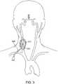
- FIG. 3shows the access sheath 220 being used to access a common carotid artery 310 for a carotid stenting procedure.
- the access sheath 220is inserted into the common carotid artery 310 via a surgical cut down 315.
- the access sheath 220has an internal lumen with openings at proximal and distal tips or regions of the access sheath 220. With a distal portion of the access sheath 220 in the carotid artery and a proximal portion external to the patient, the internal lumen provides a passageway to insert an interventional device into the artery.
- FIG. 4shows an access sheath 200 of the transcarotid access system being used to access an internal carotid artery 405 for an intracranial or neurovascular procedure.
- the arterial access sheath 200accesses the common carotid artery 310 via insertion through a transcervical puncture.
- the distal tip of the access sheath 220is advanced into the internal carotid artery ICA 320 and upward (relative to the puncture in Figure 4 ) toward distal cervical or petrous ICA 405 or beyond.
- Figures 3 and 4both show the arterial access sheath 220 being advanced upward through the patient's neck toward the patient's brain.
- the arterial access sheath 220may be advanced downward (relative to access locations in Figures 3-4 ) toward the patient's heart such as toward the aorta for example.
- U.S. Patent No. 8,545,552 entitled “Systems and Methods for Transcatheter Aortic Valve Treatment”(which is incorporated herein by reference) describes exemplary methods of directly inserting an access sheath into the carotid artery and advancing an interventional device toward the aorta and ultimately towards the aortic valve.
- an embodiment of a transcarotid arterial access sheath 220includes an elongated sheath body 222 and a proximal adaptor 224 at a proximal end of the elongated sheath body 222 of the access sheath 220.
- the elongated sheath body 222is the portion of the arterial access sheath 220 that is sized and shaped to be inserted into the artery and wherein at least a portion of the elongated sheath body is actually inserted into the artery during a procedure.
- the proximal adaptor 224includes a hemostasis valve 226 and an elongated flush line 228 having an internal lumen that communicates with an internal lumen of the sheath body 222.
- the proximal adaptor 224may have a larger diameter or cross-sectional dimension than the sheath body 222.
- the hemostasis valve 226communicates with the internal lumen of the sheath body 222 to allow introduction of devices therein while preventing or minimizing blood loss via the internal lumen during the procedure.
- the hemostasis valve 226is a static seal-type passive valve.
- the hemostasis valve 226is an adjustable-opening valve such as a Tuohy-Borst valve 227 or rotating hemostasis valve (RHV).
- the access sheath 220may terminate on the proximal end in a female Luer adaptor to which a separate hemostasis valve component may be attached, either a passive seal valve, a Tuohy-Borst valve or rotating hemostasis valve (RHV).
- the elongated sheath body 222 of the arterial access sheath 220has a diameter that is suitable or particularly optimized to provide arterial access to the carotid artery.
- the elongated sheath body 222is in a size range from 5 to 9 French, or alternately in an inner diameter range from 1.829 mm to 3.200 mm (0.072 inches to .126 inches).
- the elongated sheath body 222is a 6 or 7 French sheath.
- the sheathis an 8 French sheath.
- the elongated sheath body 222 of the arterial access sheath 220has a length from the proximal adapter 224 to a distal tip of the elongated sheath body 222 that is suitable for reaching treatment sites located in or toward the brain relative to an arterial access site in the common carotid artery CCA.
- the elongated sheath body 222i.e., the portion that can be inserted into the artery
- the access sheath 220may have a length in a range from 7 to 15 cm.
- the elongated sheath body 222has a length in the range of 10-12 cm.
- typical access sheathsmust be between 80 and 110 cm, or a guide catheter must be inserted through an arterial access sheath and advanced to the target site.
- a guide catheter through an access sheathtakes up luminal area and thus restricts the size of devices that may be introduced to the target site.
- an access sheath that allows interventional devices to reach a target site without a guide catheterhas advantages over an access sheath that requires use of a guide catheter to allow interventional devices to the target site.
- the elongated sheath body 222 of the access sheath 220may have a length in the range from 10 cm to 30 cm, depending on the desired target position of the sheath distal tip.
- the target positionis the distal CCA or proximal ICA
- the elongated sheath body 222may be in the range from 10 cm to 15 cm.
- the desired target positionis the mid to distal cervical, petrous, or cavernous segments of the ICA, the elongated sheath body 222 may be in the range from 15 to 30 cm.
- the arterial access sheath 220is configured or adapted for treatment sites or target locations located proximal to the arterial access site (i.e. towards the aorta) when the access site is in the common carotid artery.
- the treatment sitemay be the proximal region of the CCA, CCA ostium, ascending or descending aorta or aortic arch, aortic valve, coronary arteries, or other peripheral arteries.
- the appropriate length of the elongated sheath body 222depends on the distance from the target location to the access site. In this configuration, the elongated sheath body 222 is placed through an arterial access site and directed inferiorly towards the aorta.
- the access sheath 220may also include a radiopaque tip marker 230.
- the radiopaque tip markeris a metal band, for example platinum iridium alloy, embedded near the distal end of the sheath body 222 of the access sheath 220.
- the access sheath tip materialmay be a separate radiopaque material, for example a barium polymer or tungsten polymer blend.
- the sheath tipitself is configured such that when the access sheath 220 is assembled with the sheath dilator 260 to form a sheath assembly, the sheath assembly can be inserted smoothly over the sheath guide wire 300 through the arterial puncture with minimal resistance.
- the elongated sheath body 222 of the access sheath 220has a lubricious or hydrophilic coating to reduce friction during insertion into the artery.
- the distal coatingis limited to the distalmost 0.5 to 3 cm of the elongated sheath body 222, so that it facilitates insertion without compromising security of the sheath in the puncture site or the ability of the operator to firmly grasp the sheath during insertion.
- the sheathhas no coating.
- the arterial access sheath 220has features to aid in securement of the sheath during the procedure.
- the access sheath 220may have a suture eyelet 234 or one or more ribs 236 molded into or otherwise attached to the adaptor 224 (located at the proximal end of the elongated sheath body 222) which would allow the operator to suture tie the sheath hub to the patient.
- the length of the elongated sheath body 222can be in the range from 7 to 15 cm, usually being from 10 cm to 12 cm.
- the length of the elongated sheath body 222can be in the range from 10 to 30 cm, usually being from 15 cm to 25 cm.
- the elongated sheath body 222be flexible while retaining hoop strength to resist kinking or buckling. This is especially important in procedures that have limited amount of sheath insertion into the artery, and there is a steep angle of insertion as with a transcarotid access in a patient with a deep carotid artery and/or with a short neck. In these instances, there is a tendency for the sheath body tip to be directed towards the back wall of the artery due to the stiffness of the sheath.
- the distal region of the sheath bodymay be placed in a distal carotid artery which includes one or more bends, such as the petrous ICA.
- the sheath body 222is circumferentially reinforced, such as by stainless steel or nitinol braid, helical ribbon, helical wire, cut stainless steel or nitinol hypotube, cut rigid polymer, or the like, and an inner liner so that the reinforcement structure is sandwiched between an outer jacket layer and the inner liner.
- the inner linermay be a low friction material such as PTFE.
- the outer jacketmay be one or more of a group of materials including Pebax, thermoplastic polyurethane, or nylon.
- the sheath body 222may vary in flexibility over its length. This change in flexibility may be achieved by various methods.
- the outer jacketmay change in durometer and/or material at various sections.
- the reinforcement structure or the materialsmay change over the length of the sheath body.
- the flexural stiffness of the distalmost sectionis one third to one tenth the flexural stiffness of the remainder of the sheath body 222.
- the distalmost sectionhas a flexural stiffness (E ⁇ I) in the range 50 to 300 N-mm 2 and the remaining portion of the sheath body 222 has a flexural stiffness in the range 500 to 1500 N-mm 2 , where E is the elastic modulus and I is the area moment of inertia of the device.
- the flexible, distal most sectioncomprises a significant portion of the sheath body 222 which may be expressed as a ratio.
- the ratio of length of the flexible, distalmost section to the overall length of the sheath body 222is at least one tenth and at most one half the length of the entire sheath body 222.
- the arterial access sheathis configured to access a carotid artery bifurcation or proximal internal carotid artery ICA from a CCA access site.
- an embodiment of the sheath body 222has a distalmost section 223 which is 3 to 4 cm and the overall sheath body 222 is 10 to 12 cm.
- the ratio of length of the flexible, distalmost section to the overall length of the sheath body 222is about one forth to one half the overall length of the sheath body 222.
- the distalmost sectionis 2 to 4 cm
- the transition sectionis 1 to 2 cm
- the overall sheath body 222is 10 to 12 cm, or expressed as a ratio
- the distalmost flexible section and the transition sectioncollectively form at least one fourth and at most one half the entire length of the sheath body.
- the sheath body 222 of the arterial access sheathis configured to be inserted more distally into the internal carotid artery relative to the arterial access location, and possibly into the intracranial section of the internal carotid artery.
- a distalmost section 223 of the elongated sheath body 222is 2.5 to 5 cm and the overall sheath body 222 is 20 to 30 cm in length.
- the ratio of length of the flexible, distalmost section to the overall length of the sheath bodyis one tenth to one quarter of the entire sheath body 222.
- the distalmost flexible section and the proximal section 231there is a transition section 225 between the distalmost flexible section and the proximal section 231, in which the distalmost section is 2.5 to 5 cm, the transition section is 2 to 10 cm and the overall sheath body 222 is 20 to 30 cm.
- the distalmost flexible section and the transition sectioncollectively form at least one sixth and at most one half the entire length of the sheath body.
- the sheathhas a structure configured to center the sheath body tip in the lumen of the artery such that the longitudinal axis of the distal region of the sheath body is generally parallel with the longitudinal or center axis of the lumen of the vessel.
- the sheath alignment featureis an inflatable or enlargeable bumper, for example a balloon 608, located on an outer wall of the arterial access sheath 220. The balloon 608 may be increased in size to exert a force on inner the arterial that contacts and pushes the elongated body 222 of the aerial access sheath away from the arterial wall.
- the sheath alignment featureis one or more mechanical structures on the sheath body that can be actuated to extend outward from the sheath tip.
- the sheath body 222is configured to be inserted into the artery such that a particular edge of the arterial access is against the posterior wall of the artery.
- the sheath alignment featureneed only extend outward from one direction relative to the longitudinal axis of the sheath body 222 to lift or push the sheath tip away from the posterior arterial wall.
- the inflatable bumper 608is a blister on one side of the sheath body.
- the mechanical featureextends only on one side of the sheath body.
- the sheath body 222is pre-shaped so that after sheath insertion the tip is more aligned with the long axis of the vessel, even at a steep sheath insertion angle.
- the sheath bodyis generally straight when the dilator is assembled with the sheath during sheath insertion over the sheath guide wire, but once the dilator and guidewire are removed, the distalmost section of the sheath body assumes a curved or angled shape.
- the sheath bodyis shaped such that the distalmost 0.5 to 1 cm section is angled from 10 to 30 degrees, as measured from the main axis of the sheath body, with a radius of curvature about 12.7 mm (0.5 inch).
- the sheathmay be heat set in the angled or curved shape during manufacture.
- the reinforcement structuremay be constructed out of nitinol and heat shaped into the curved or angled shape during manufacture.
- an additional spring elementmay be added to the sheath body, for example a strip of spring steel or nitinol, with the correct shape, added to the reinforcement layer of the sheath.
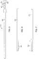
- FIG. 7shows such an embodiment of the sheath body 222 where the sheath body has stepped or tapered configuration having a reduced diameter distal region 705 (with the reduced diameter being relative to the remainder of the sheath).
- the distal region 705 of the stepped sheathcan be sized for insertion into the carotid artery, typically having an inner diameter in the range from 1.651 mm or 2.921 mm (0.065 inch or 0.115 inch) with the remaining proximal region of the sheath having larger outside and luminal diameters, with the inner diameter typically being in the range from 2.794 mm to 3.429 mm (0.110 inch to 0.135 inch).
- the larger luminal diameter of the remainder of the sheath bodyminimizes the overall flow resistance through the sheath.
- the reduced-diameter distal section 705has a length of approximately 2 cm to 4 cm.
- the relatively short length of the reduced-diameter distal section 705permits this section to be positioned in the common carotid artery CCA via a transcarotid approach with reduced risk that the distal end of the sheath body will contact the bifurcation B.
- the reduced diameter sectionalso permits a reduction in size of the arteriotomy for introducing the sheath into the artery while having a minimal impact in the level of flow resistance.
- the reduced distal diameter sectionmay be more flexible and thus more conformal to the lumen of the vessel.
- FIG. 8shows an embodiment of an arterial access sheath 220 with an inflatable balloon 805 on a distal region that is inflated via an inflation line 810 that connect an internal inflation lumen in the sheath body 222 to a stopcock 229 which in turn may be connected to an inflation device.
- a Y-arm 815may be connected to a passive or active aspiration source to further reduce the risk of distal emboli.
- this embodimentis configured to move the hands of the operator, and in fact his or her entire body, away from the target site and therefore from the image intensifier that is used to image the target site fluoroscopically, thus reducing the radiation exposure to the user during the procedure. Essentially, this lengthens the portion of the arterial access sheath 220 that is outside the body. This portion can be a larger inner and outer diameter than the sheath body 222.
- the arterial access sheath 220has an insertable, elongated sheath body 222 (i.e. the portion configured to insert into the artery) and a proximal extension portion 905.
- the sheath body 222has an inner diameter of about 2.210 mm (0.087 inch) and an outer diameter of about 2.642 mm (.104 inch), corresponding to a 6 French sheath size, and the proximal extension has an inner diameter of about 2.540 to 3.175 mm (.100 inch to .125 inch) and an outer diameter of about 3.81 mm to 4.445 mm (.150 inch to .175 inch).
- the sheath body 222has an inner diameter of about 2.870 mm (.113 inch) and an outer diameter of about 3.454 mm (.136 inch), corresponding to an 8 French sheath size, and the proximal extension has an inner diameter of about 3.175 mm (.125 inch) and an outer diameter of about 4.445 mm (.175 inch).
- the sheath body 222is stepped with a smaller diameter distal section 705 to further reduce flow restriction, as in Figure 7 .
- the proximal extension 905is a length suitable to meaningfully reduce the radiation exposure to the user during a transcarotid access procedure.
- the proximal extension 905is between 10 and 25 cm, or between 15 and 20 cm. Alternately, the proximal extension 905 has a length configured to provide a distance of between about 30 cm and 60 cm between the hemostasis valve 226 and the distal tip of the sheath body, depending on the insertable length of the access sheath.
- a connector structure 915can connect the elongated sheath body 222 to the proximal extension 905.
- the connector structure 915may include a suture eyelet 920 and/or ribs 925 to assist in securing the access sheath to the patient.
- the hemostasis valve 226is a static seal-type passive valve.
- the hemostasis valve 226is an adjustable-opening valve such as a Tuohy-Borst valve 227 or rotating hemostasis valve (RHV).
- the proximal extensionmay terminate on the proximal end in a female Luer adaptor to which a separate hemostasis valve component may be attached, either a passive seal valve, a Tuohy-Borst valve or rotating hemostasis valve (RHV).
- vessel closure devicesrequires an arterial access sheath with a maximum distance of about 15 cm between distal tip of the sheath body to the proximal aspect of the hemostasis valve, with sheath body 222 of about 11 cm and the remaining 4 cm comprising the length of the proximal hemostasis valve; thus if the access sheath has a distance of greater than 15 cm it is desirable to remove the proximal extension 905 at the end of the procedure.
- the proximal extension 905is removable in such a way that after removal, hemostasis is maintained.
- a hemostasis valveis built into the connector 915 between the sheath body 222 and the proximal extension 905.
- the hemostasis valveis opened when the proximal extension 905 is attached to allow fluid communication and insertion of devices, but prevents blood flowing out of the sheath when the proximal extension 905 is removed.
- the proximal extension 905can be removed, reducing the distance between the proximal aspect of the hemostasis valve and sheath tip from greater than 15 cm to equal or less than 15 cm and thus allowing a vessel closure device to be used with the access sheath 220 to close the access site.
- the arterial sheath embodiment shown in Figure 10has a flow line 1005 with internal lumen to a Y-arm 1015 of the connector 915.
- This flow linehas a lumen fluidly connected to a lumen in the sheath body.
- the flow line 1005may be connected to a lower pressure return site such as a venous return site or a reservoir.
- the flow line 1005may also be connected to an aspiration source such as a pump or a syringe.
- an occlusion elementmay also be included on the distal end of the sheath body 222, for example an occlusion balloon. This may be desirable in percutaneous procedures, where the vessel cannot be occluded by vascular surgical means such as vessel loops or vascular clamps.
- sheath body insertion into the arterymay be desirable to limit the amount of sheath body insertion into the artery, for example in procedures where the target area is very close to the arterial access site.
- the sheath tipIn a stent procedure of the carotid artery bifurcation, for example, the sheath tip should be positioned proximal of the treatment site (relative to the access location) so that it does not interfere with stent deployment or enter the diseased area and possibly cause emboli to get knocked loose.
- a sheath stopper 1105is slideably connected or mounted over the outside of the distal portion of the sheath body.
- the sheath stopper 1105is shorter than the distal portion of the sheath, effectively shortening the insertable portion of the sheath body 222 by creating a positive stop at a certain length along the sheath body 222.
- the sheath stopper 1105may be a tube that slidably fits over the sheath body 222 with a length that, when positioned on the sheath body 222, leaves a distal portion of the sheath body exposed. This length can be in the range 2 to 4 cm. More particularly, the length is 2.5 cm.
- the distal end of the sheath stopper 1105may be angled and oriented such that the angle sits flush with the vessel and serves as a stop against the arterial wall when the sheath is inserted into the artery when the vessel is inserted into the artery, as shown in Figure 11A .
- the distal end of the sheath stoppermay be formed into an angled flange 1115 that contacts the arterial wall, as shown in Figure 11B .
- the flange 1115is rounded or has an atraumatic shape to create a more positive and atraumatic stop against the arterial wall.
- the sheath stopper 1105may be permanently secured to the arterial sheath, for example the proximal end of the sheath stopper may be adhered to connector 915 of the arterial access sheath.
- the sheath stopper 1105may be removable from the arterial access sheath 220 by the user so it can be optionally utilized in a procedure.
- the sheath stopper 1105may have a locking feature on the proximal portion that engages with a corresponding locking features on the connector 915, for example slots or recesses on the proximal sheath stopper engaging protrusions on the connector. Other locking features may also be utilized.
- the sheathmay conform to a bayonet shape when secured to the patient.
- the bayonet shapemay comprise a first portion that extends along a first axis and a second portion that extends along a second axis that is axially offset from the first axis and/or non-parallel to the first axis.
- the springiness of the sheath bodycauses this shape to exert a force on the vessel at the site of insertion and increase the tendency of the sheath to come out of the vessel if not properly secured.
- the sheath stoppermay be pre-shaped into a curved or bayonet shape so that the stress of the sheath body when curved is imparted onto the sheath stopper rather than on the vessel.
- the sheath stoppermay be made from springy but bendable material or include a spring element such as a stainless steel or nitinol wire or strip, so that when the dilator is inserted into the sheath and sheath stopper assembly, the sheath is relatively straight, but when the dilator is removed the sheath stopper assumes the pre-curved shape to reduce the force the sheath imparts on the vessel wall.
- the sheath stoppermay be made of malleable material or include a malleable element such as a bendable metal wire or strip, so that it can be shaped after the sheath is inserted into a desired curvature, again to reduce the stress the sheath imparts on the vessel wall.
- the sheath dilator 260is a component of the transcarotid access sheath system 200.
- the sheath dilator 260is an elongated body that is inserted into the artery and enables smooth insertion of the access sheath 220 over the sheath guidewire 300 through a puncture site in the arterial wall.
- the distal end of the dilator 260is generally tapered to allow the dilator to be inserted over the sheath guidewire 300 into the artery, and to dilate the needle puncture site to a larger diameter for insertion of the access sheath 220 itself.
- the dilator 260has a tapered end 268 with a taper that is generally between 6 and 12 degrees total included angle (relative to a longitudinal axis of the dilator), with a radiused leading edge.
- Sheath dilatorsare typically locked to the access sheath when assembled for insertion into the artery.
- a proximal hub 264 of the sheath dilator 260is structured to snap into or over a corresponding structure on the hemostasis valve 226 of the arterial access sheath 220.
- An inner lumen of the dilator 260accommodates a sheath guidewire 300, with an inner diameter of between 0.940 to 1.041 mm (.037 to .041 inch), depending on the sheath guide wire size for example.
- the distal section of the sheath dilator 260may be more flexible, to correspond with an increased flexible section of the access sheath 220.
- the distal 2 to 5 cm of the sheath dilator 260may be 20 to 50% more flexible than the proximal portion of the sheath dilator 260.
- This embodimentwould allow a sheath and dilator being inserted to accommodate a steep insertion angle, as is often the case in a transcarotid access procedure, with a smoother insertion over the guidewire while still maintaining columnar support of the dilator.
- the columnar supportis desirable to provide the insertion force required to dilate the puncture site and insert the access sheath.
- the sheath dilator tapered end 268is configured to provide a smooth transition from a smaller wire size to the access sheath.
- the sheath guide wireis 0.457 mm (.018 inch) and the inner dilator lumen is in the range 0.508 to 0.559 mm (.020 to .022 inch).
- the sheath guide wireis 0.356 mm (.014 inch) and the inner dilator lumen is in the range 0.406 to 0.457 mm (.016 to .018 inch).
- the taperis similarly modified, for example the taper length is longer to accommodate a taper from a smaller diameter to the inner diameter of the access sheath, or may comprise two taper angles to provide a smooth transition from the smaller diameter wire to the access sheath without overly lengthening the overall length of the taper.
- the distal tip of the sheath body 222 of the arterial access sheath 220in the mid to distal cervical, petrous, or cavernous segments of the ICA as described above. These segments have curvature often greater than 90 degrees. In may be desirable to have a sheath dilator with a softer and longer taper, to be able to navigate these bends easily without risk of injury to the arteries. However, in order to insert the sheath through the arterial puncture, the dilator desirably has a certain stiffness and taper to provide the dilating force.
- the transcarotid access sheath system 200is supplied or included in a kit that includes two or more tapered dilators 260A and 260B.
- the first tapered dilator 260Ais used with the arterial access device to gain entry into the artery, and is thus sized and constructed in a manner similar to standard introducer sheath dilators.
- Example materials that may be used for the tapered dilatorinclude, for example, high density polyethylene, 72D Pebax, 90D Pebax, or equivalent stiffness and lubricity material.
- a second tapered dilator 260B of the kitmay be supplied with the arterial access device with a softer distal section or a distal section that has a lower bending stiffness relative to the distal section of the first tapered dilator. That is, the second dilator has a distal region that is softer, more flexible, or articulates or bends more easily than a corresponding distal region of the first dilator. The distal region of the second dilator thus bends more easily than the corresponding distal region of the first dilator.
- the distal section of the first dilator 260Ahas a bending stiffness in the range of 50 to 100 N-mm 2 and the distal section of the second dilator 260B has a bending stiffness in the range of 5 to 15 N-mm 2 .
- the second dilator 260B(which has a distal section with a lower bending stiffness) may be exchanged with the initial, first dilator such that the arterial access device may be inserted into the internal carotid artery and around curvature in the artery without undue force or trauma on the vessel due to the softer distal section of the second dilator.
- the distal section of the soft, second dilatormay be, for example, 35 or 40D Pebax, with a proximal portion made of, for example 72D Pebax.
- An intermediate mid portion or portionsmay be included on the second dilator to provide a smooth transition between the soft distal section and the stiffer proximal section.
- one or both dilatorsmay have radiopaque tip markers so that the dilator tip position is visible on fluoroscopy.
- the radiopaque markeris a section of tungsten loaded Pebax or polyurethane which is heat welded to the distal tip of the dilator.
- Other radiopaque materialsmay similarly be used to create a radiopaque marker at the distal tip.
- one or both dilatorsmay be configured such that the distal section of the dilator is constructed from a tapered single-lumen tube, but the proximal portion of the dilator and any adaptor on the proximal end has a side opening.
- Figure 12shows an example of a dilator 1205 formed of an elongated member sized and shaped to be inserted into an artery, and a proximal hub 1210.
- the dilatorhas a side opening 1215, such as a slot, that extends along at least a portion of the length of the dilator 1205 such as along the elongated body and the proximal hub 1210.
- the side opening 1215is located only on a proximal region of the dilator 1205 and through the proximal hub 1210 although this may vary.
- the side opening 1215provides access to an internal lumen of the dilator 1205, such as to insert and/or remove a guidewire into or from the lumen.
- An annular, movable sleeve 1220 with a slot on one sideis located at or near the proximal hub 1210 of the dilator 1205.
- the sleeve 1220may be moved, such as via rotation, about a longitudinal axis of the hub 1210, as described below. Note that the distal end of the dilator 1205 has a tapered configuration for dilating tissue.
- Figure 13shows an enlarged view of the proximal region of the dilator 1205.
- the dilator 1205has a side opening 1215 in the form of a slot that extends along the length of the dilator 1205 and the proximal hub 1210.
- the sleeve 1220is positioned around the outer periphery of the dilator and is shaped such that it covers at least a portion of the side opening 1215.
- the sleeve 1220can prevent a guidewire positioned inside the dilator 1205 from exiting the dilator via the side opening 1215.
- the sleeve 1220is rotatable relative to the dilator 1205 and proximal hub 1210.
- the sleeve 1220is rotatable about a longitudinal axis of the dilator 1205 although other types of relative movement are within the scope of this disclosure.
- the sleeve 1220has a slot 1225 that can be aligned with the side opening 1215.
- the slot 1225 and side opening 1215collectively provide an opening for a guidewire to be inserted or removed from the internal lumen of the dilator 1205.
- the sleeve 1220can be rotated between the position shown in Figure 13 (where it covers the side opening 1215) and the position shown in Figure 14 (where the side opening is uncovered due to the slot 1225 being aligned with the side opening 1215.)
- a sheath guide wiresuch as an 0.889 mm (0.035 inch) guidewire, is inserted into the common carotid artery, either using a Modified Seldinger technique or a micropuncture technique.
- the distal end of the guidewirecan be positioned into the internal or external carotid artery, or stop in the common carotid artery short of the bifurcation.
- the arterial access sheath with the first, stiffer dilatoris inserted over the 0.889 mm (0.035 inch) wire into the artery.
- the arterial access sheathis inserted such that at least 2.5 cm of sheath body 222 is in the artery.
- the arterial access sheathmay be directed further, and into the internal carotid artery.
- the first dilatoris removed while keeping both the arterial access sheath and the 0.889 mm (0.035 inch) wire in place.
- the side opening 1215 in the proximal portion of the dilatorallows the dilator to be removed in a "rapid exchange" fashion such that most of the guidewire outside the access device may be grasped directly during dilator removal.
- the second dilatoris then loaded on to the 0.889 mm (0.035 inch) wire and inserted into the sheath.
- a dilator with a side opening 1215 in the proximal portion of the dilatormay be used to allow the 0.889 mm (0.035 inch) wire to be grasped directly during guide wire insertion in a "rapid exchange" technique.
- one or more standard dilatorsmay be used without side openings. If a standard dilator without a side opening is used, after the access device is inserted into the artery over a guide wire with the first dilator, the first dilator may be removed together with the guidewire, leaving only the access device in place. The second dilator with a guide wire preloaded into the central lumen may be inserted together into the arterial access device. Once fully inserted, the access device and second dilator with softer tip may be advanced distally up the internal carotid artery as above. In this alternate method, the initial guide wire may be used with both dilators, or may be exchanged for a softer tipped guide wire when inserted with the second softer tipped dilator.
- a wire that can offer good supportsuch as an 0.889 mm (0.035 inch) wire may be desirable to initially introduce the access sheath into the CCA.
- the usermay exchange both the dilator and 0.889 mm (0.035 inch) wire for a softer dilator and smaller guide wire in the range 0.356 to 0.457 mm (.014 to .018 inch).
- the usermay wish to position an 0.356 mm (.014 inch) guidewire which he or she will subsequently to introduce an interventional device, while the sheath and dilator are still in place.
- the dilatormay offer access and support for this guide wire, and in instances of severe access sheath angle may aid in directing the wire away from the posterior wall of the artery so that the wire may be safely advanced into the vascular lumen without risk of luminal injury.
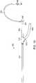
- the sheath dilator 260is a two-part dilator assembly, with an inner dilator 269 and an outer dilator 270 that slidably attach to one another in a co-axial arrangement. Both dilators have proximal hubs 264a and 264b. When the two dilators are assembled together, the two hubs 264a and 264b have features which allow them to be locked together, e.g. a snap fit or a threaded fit, so that the two dilators can be handled as one unit.
- the inner dilator 269has a proximal hub 264b which includes a rotating coupler with internal threads that engage external threads on the proximal hub 264a of the outer dilator 270.
- the inner dilator 269effectively transforms the dilator assembly from an 0.889 mm (0.035 inch) or 0.965 mm (0.038 inch) wire compatible dilator to an 0.356 mm or 0.457 mm (.014 or .018 inch) wire compatible dilator, and extends out the distal end of the outer dilator.
- the inner dilatorhas an angled tip 276 that is bent or angled relative to a longitudinal axis of the remainder of the dilator. In an embodiment, the angle is a 45 degree angle. This angled tip 276 allows the user to direct the guidewire into one or another branch vessel more easily.
- the inner dilatormay have a tapered tip, straight as shown in Figure 15 or an angled tip as shown in Figure 16 . Alternately, the inner dilator may have a constant outer diameter to the distal end, with a rounded leading edge.
- the inner dilatorhas a radiopaque marker 274 at or near the distal tip to aid in visualization of the dilator under fluoroscopy.
- the inner dilatoris reinforced to make it more torquable to aid in directing the angled tip in a particular direction.
- the dilatormay have a coil or braid reinforcement layer.
- FIG. 17An alternate embodiment, shown in Figure 17 , allows two separate wire sizes to be used with the dilator.
- This embodimentincludes a dilator 1705 with two guide wire internal lumens that extend along the length of the device.
- Figure 17shows the distal end of this embodiment.
- one lumen 1805is configured for an 0.889 mm (.035 inch) or 0.965 mm (.038 inch) guidewire, and the other lumen 1815 is for a an 0.356 to 0.457 mm (.014 to .018 inch) guide wire.
- the larger lumen 1805is centered around the centerline of the taper 268, whereas the smaller lumen 1815 is offset from the centerline of the taper.
- the access sheathis introduced into the artery over the larger guidewire, which is positioned in the larger lumen 1805.
- an interventional wirecan be placed through the second lumen 1815.
- the larger guidewire and dilatorare then removed from the access sheath and the interventional wire may then be used to insert interventional devices through the arterial sheath into the artery and advanced to the treatment site as above.
- Arterial access sheathsare typically introduced into the artery over a sheath guidewire of 0.889 mm (.035 inch) or 0.965 mm (0.038 inch).
- the inner diameter and taper length of the distal tip of the dilatorare sized to fit with such a guidewire.
- Some sheathsfor example for radial artery access, are sized to accommodate a sheath guidewire of 0.457 mm (.018 inch) diameter, with a corresponding dilator having a distal tip inner diameter and taper length.
- the sheath guidewiremay have an atraumatic straight, angled, or J-tip. The guidewire smoothly transitions to a stiffer segment on the proximal end.
- This configurationallows atraumatic entry and advancement of the wire into the artery while allowing support for the sheath when the sheath is introduced into the artery over the wire.
- the transition from the atraumatic tipis about 4 to 9 cm to the stiffer section.
- the sheathis usually inserted 15 to 20 cm into the artery, so that the stiffer segment of the wire is at the arterial entry site when the sheath is being inserted.
- a transcarotid sheath guidewirehas an atraumatic tip section but have a very distal and short transition to a stiffer section.
- the soft tip sectionis 1.5 to 2.5 cm, followed by a transition section with length from 3 to 5 cm, followed by a stiffer proximal segment, with the stiffer proximal section comprising the remainder of the wire.
- the sheath guidewiremay have guide wire markings 318 to help the user determine where the tip of the wire is with respect to the dilator. For example, there may be a marking on the proximal end of the wire corresponding to when the tip of the wire is about to exit the micro access cannula tip. This marking would provide rapid wire position feedback to help the user limit the amount of wire insertion.
- the wiremay include an additional mark to let the user know the wire has existed the cannula by a set distance, for example 5 cm.
- a micro access kit 100 for initial transcarotid accessincludes an access needle 120, an access guidewire 140, and a micro access cannula 160.
- the micro access cannula 160includes a body 162 and an inner dilator 168 slidably positioned within a lumen of the body 162.
- the initial needle puncturemay be with a 21G or 22G access needle, or an 18G needle if the Modified Seldinger technique is used.
- Percutaneous access of the carotid arteryis typically more challenging than of the femoral artery.
- the carotid arteryis a thicker-walled artery, it is surrounded by a tissue sleeve known as the carotid sheath, and it is not anchored down as much by surrounding musculature, therefore the initial needle stick is more difficult and must be done with more force, onto an artery that is less stable, thus increasing the risk of mis-placed puncture, arterial dissection, or back wall puncture.
- a smaller initial needle puncturefor example a 23G or 24G needle, increases the ease of needle entry and reduce these risks.
- the sheath guidewireshould be accordingly sized to fit into the smaller needle, for example a 0.406 or 0.356 mm (.016 or .014 inch) wire.
- the access needle 120may include a textured surface on the distal end to render it visible on ultrasound, to aid in ultrasound-guided insertion of the needle into the artery.
- the needle lengthmay be in a range from 4 cm to 8 cm in length.
- micro access guide wireshave a transition segment from a floppy distal tip to a core section that is stiffer than the distal tip or distal region.
- Such micro access guidewiresare typically 0.457 mm (.018 inch) in diameter, with a floppy, distal segment of about 1-2 cm, and a transition zone of 5-6 cm to the stiffer segment.
- a transcarotid access guidewireis from 0.356 to 0.457 (.014 to .018 inch) in diameter, and has a floppy segment of 1 cm, a transition zone of 2-3 cm to bring the stiff supportive section much closer to the distal tip. This will allow the user to have good support for his micro access cannula insertion even in steep access angles and limitations on wire insertion length.
- the micro access guide wiremay have guide wire markings 143 to help the user determine where the tip of the wire is with respect to the micro cannula. For example, a marking can be located on the proximal end of the wire corresponding to when the tip of the wire is about to exit the micro cannula. This marking would provide rapid wire position feedback to help the user limit the amount of wire insertion.
- the wiremay include an additional mark to let the user know the wire has existed the dilator by a set distance, for example 5 cm.
- the micro access cannulaitself may be configured for transcarotid insertion.
- the micro access cannula 160includes a cannula 162 and an inner dilator 168 with a tapered tip.
- the inner dilator 168provides a smooth transition between the cannula and the access guide wire.
- the cannulais sized to receive the 0.889 mm (.035 inch) wire, with inner diameter in the range 0.965 to 1.067 mm (.038 to .042 inch).
- a micro access cannula 160is configured for transcarotid access.
- the dilator of the cannulamay be sized for a smaller 0.356 mm (.014 inch) access guide wire 140.
- the cannulaitself may have depth marking to aid the user in limiting the amount of insertion.
- the micro access cannula 160has a radiopaque marker 164 at the distal tip of the cannula 162 to help the user visualize the tip location under fluoroscopy. This is useful for example in cases where the user may want to position the cannula in the ICA or ECA, for example.
- An embodiment of an access sheath kitcomprises an access sheath, sheath dilator, and sheath guidewire all configured for transcarotid access as described above.
- a micro access kitcomprises an access needle, a micro access guide wire, and a micro access cannula and dilator wherein the guidewire is 0.356 mm (.014 inch) and the micro access cannula and dilator are sized to be compatible with the 0.356 mm (.014 inch) guide wire.
- an access kitcomprises the access sheath, sheath dilator, sheath guide wire, access needle, micro access guide wire and micro access cannula and dilator, all configured for transcarotid access.
- the access guidewireis also used as the sheath guide wire.
- the access kitcomprises an access needle, access guide wire, access sheath and dilator.
- the sheath and dilatoruse the access guide wire to be inserted into the vessel, thereby avoiding the steps required to exchange up to a larger sheath guidewire.
- the dilator taper length and inner lumenis sized to be compatible with the smaller access guide wire.
- the access guide wireis 0.457 (.018 inch).
- the access guide wireis 0.406 mm (.016 inch).
- the access guide wireis 0.356 mm (.014 inch).
- transcarotid access systemIn an exemplary transcarotid procedure to treat a carotid artery stenosis, the user starts by performing a cut down to the common carotid artery. The user then inserts an access needle 120 into the common carotid artery at the desired access site. An access guide wire 140 with a taper configured for transcarotid access is inserted through the needle into the common carotid artery and advanced into the CCA. The access needle 120 is removed and a micro access cannula 160 is inserted over the wire 140 into the CCA. The micro access cannula is inserted a desired depth using the marks 166 on the cannula as a guide, to prevent over insertion.
- the userremoves the cannula inner dilator 168 and guide wire 140, leaving the cannula 162 in place. If desired, the user performs an angiogram through the cannula 162. The user then places sheath guide wire 300 through the cannula, using guide wire markings 318 to aid in inserting the wire to a desired insertion length.
- the cannula 162is removed from the guidewire and the access sheath 220 and sheath dilator 260 are inserted as an assembly over the sheath guidewire 300 into the CCA.
- the sheath stopper flange 1115 of the sheath stopper 1105limits the insertion length of the arterial sheath. Once positioned, the dilator 260 and guidewire 300 are removed.
- the sheathis then sutured to the patient using the securing eyelets 234 and/or ribs 236.
- An interventional procedureis then performed by introduction of interventional devices through hemostasis valve 226 on the proximal end of the arterial sheath and to the desire treatment site. Contrast injections may be made as desired during the procedure via the flush arm 228 on the arterial sheath 220.
- the sheath guidewire 300is placed into the CCA via a single needle puncture with a larger access needle, for example an 18G needle.
- a larger access needlefor example an 18G needle.
- the access cannula and access guide wireare not needed. This embodiment reduces the number of steps required to access the artery, and in some circumstances may be desirable to the user.
- the sheath dilatoris a two-part sheath dilator assembly 260 as shown in Figure 15 , with an inner dilator 269 and an outer dilator 270.
- the outer dilator 270is configured to receive an .035" sheath guide wire 300 and to provide a smooth transition from the .035" wire to the access sheath 220.
- the inner dilator 269is configured to receive a smaller guide wire in the range 0.356 to 0.457 mm (.014 to 0.018 inch) and to provide a smooth transition from the smaller guide wire to the outer dilator 270.
- the access sheath and outer sheath dilator 270are inserted over an 0.889 mm (.035 inch) sheath guidewire 300 into the CCA.
- the guidewireis then removed and an inner sheath dilator 269 is inserted into the outer sheath dilator.
- the inner sheath dilatorhas an angled tip 276 as seen in Figure 16 .
- An interventional 0.356 mm (.014 inch) guide wireis inserted through the inner sheath dilator and is directed to the target treatment site using the angled tip to aid in guide wire positioning.
- the inner sheath dilatorhas a straight tip and is used to aid in positioning the guide wire safely into the CCA.
- the sheath dilator 260 and sheath .035" guide wire 300are then removed, and the intervention proceeds.
- the sheath dilatoris a two lumen sheath dilator 1705.
- the sheath and dilatorare inserted over the sheath guide wire 300, with the sheath guidewire positioned in the larger lumen 1805 of dilator 1705.
- an interventional 0.356 mm (.014 inch) guide wireis positioned through the smaller lumen 1815.
- the dilatorprovides distal support and maintains the position of the sheath tip in the axial direction of the vessel lumen, thus allowing a potentially safer and easier advancement of the 0.356 mm (.014 inch) wire than if the dilator were removed and the sheath tip was directed at least partially towards to posterior wall of the artery.
- the occlusion stepmay be performed via vascular surgical means such as with a vessel loop, tourniquet, or vascular clamp.
- the access sheath 220has an occlusion element such as an occlusion balloon 250 on the distal tip.
- the balloonis inflated when CCA occlusion is desired.
- the arterial sheath 220has a Y connection to a flow line 256.
- the flow linemay be connected to a return site with a pressure lower than arterial pressure to create a pressure gradient that results in reverse flow through the shunt, for example an external reservoir or a central venous return site like the femoral vein or the internal jugular vein.
- the flow linemay be connected to an aspiration source such as an aspiration pump or syringe.
- a transcarotid access systemis used to perform a percutaneous neurointerventional procedure.
- the userperforms a percutaneous puncture of the common carotid artery CCA with an access needle 120 at the desired access site. Ultrasound may be used to accurately identify a suitable access site and guide the needle puncture.
- An access guide wire 140is inserted through the needle into the common carotid artery and advanced into the CCA.
- the access needle 120is removed and a micro access cannula 160 is inserted over the wire 140 into the CCA.
- the userremoves the cannula inner dilator 168 and guide wire 140, leaving the cannula 162 in place. If desired, the user performs an angiogram through the cannula 162.
- the cannula 162is removed from the guidewire and the access sheath 220 and sheath dilator 260 are inserted as an assembly over the sheath guidewire 300 into the CCA.
- the smaller access guide wire 140is used to position the access sheath 220 and sheath dilator 260 into the CCA.
- the sheath dilator tapered tip 266has been configured to transition smoothly from the access guide wire 140 to the access sheath 220.
- the access needleis 21G and the access guide wire is 0.457 mm (.018 inch).
- the access needleis 24G and the access guide wire is 0.356 mm (.014 inch).
- the sheath dilatormay be replaced with a softer sheath dilator so that the sheath may be advanced without risk of damaging the distal ICA.
- the softer dilatorhas a distal radiopaque marker so that the user may easily visualize the leading edge of the sheath and dilator assembly during positioning of the sheath.
- the .035" guide wiremay be removed and an inner dilator with a smaller guide wire in the range 0.356 to 0.457 mm (.014 to .018 inch) may be inserted into sheath dilator.
- the sheath dilator assembly with the inner dilator and smaller guide wiremay be then positioned more distally in the ICA with reduced risk of vessel trauma.
- the CCA or ICAmay be desirable to occlude the CCA or ICA during portions of the procedure to reduce the chance of distal emboli flowing to the brain.
- the CCA or ICAis occluded by means of an occlusion balloon 250 on the access sheath 220.
- Itmay also be desireable to connect the arterial sheath to a flow shunt, for example to create a reverse flow system around the area of the treatment site to minimize distal emboli.
- the arterial sheath 220has a Y connection to a flow line 256.
- the flow linemay be connected to a return site with a pressure lower than arterial pressure to create a pressure gradient that results in reverse flow through the shunt.
- the flow linemay be connected to an aspiration source such as an aspiration pump or syringe.
Landscapes
- Health & Medical Sciences (AREA)
- Life Sciences & Earth Sciences (AREA)
- Heart & Thoracic Surgery (AREA)
- Public Health (AREA)
- Biomedical Technology (AREA)
- Engineering & Computer Science (AREA)
- Animal Behavior & Ethology (AREA)
- General Health & Medical Sciences (AREA)
- Veterinary Medicine (AREA)
- Anesthesiology (AREA)
- Hematology (AREA)
- Pulmonology (AREA)
- Biophysics (AREA)
- Surgery (AREA)
- Nuclear Medicine, Radiotherapy & Molecular Imaging (AREA)
- Medical Informatics (AREA)
- Molecular Biology (AREA)
- Vascular Medicine (AREA)
- Media Introduction/Drainage Providing Device (AREA)
- Surgical Instruments (AREA)
Abstract
Description
- This application claims priority to
U.S. Patent Application Serial No. Serial No. 14/575,199 entitled "METHODS AND DEVICES FOR TRANSCAROTID ACCESS" and filed December 18, 2014 U.S. Patent Application Serial No. 14/537,316 entitled "METHODS AND DEVICES FOR TRANSCAROTID ACCESS" and filed November 10, 2014 U.S. Provisional Application Serial No. 62/046,112, entitled "METHODS AND DEVICES FOR TRANSCAROTID ACCESS" filed on September 4, 2014 U.S. Provisional Application Serial No. 62/075,169, entitled "METHODS AND DEVICES FOR TRANSCAROTID ACCESS" filed on November 4, 2014 - The present disclosure relates generally to medical methods, systems, and devices for performing endovascular interventions. More particularly, the present disclosure relates to methods and systems for access directly into the carotid artery to perform interventional procedures in the treatment of vascular disease and other diseases associated with the vasculature.
- Interventional procedures are performed to treat vascular disease, for example stenosis, occlusions, aneurysms, or fistulae. Interventional procedures are also used to perform procedures on organs or tissue targets that are accessible via blood vessels, for example denervation or ablation of tissue to intervene in nerve conduction, embolization of vessels to restrict blood flow to tumors or other tissue, and delivery of drugs, contrast, or other agents to intra or extravascular targets for therapeutic or diagnostic purposes. Interventional procedures are typically divided into coronary, neurovascular, and peripheral vascular categories. Most procedures are performed in the arterial system via an arterial access site.
- Methods for gaining arterial access to perform these procedures are well-established, and fall into two broad categories: percutaneous access and surgical cut-down. The majority of interventional procedures utilize a percutaneous access. For this access method, a needle puncture is made from the skin, through the subcutaneous tissue and muscle layers to the vessel wall, and into the vessel itself. Vascular ultrasound is often used to image the vessel and surrounding structures, and facilitate accurate insertion of the needle into the vessel. Depending on the size of the artery and of the access device, the method will vary, for example a Seldinger technique or modified Seldinger technique consists of placing a sheath guide wire through the needle into the vessel. Typically the sheath guide wire is 0.889 mm or 0.965 mm (0.035 inch or 0.038 inch). In some instances, a micro-puncture or micro access technique is used whereby the vessel is initially accessed by a small gauge needle, and successively dilated up by a 4F micropuncture cannula through which the sheath guidewire is placed. Once the guidewire is placed, an access sheath and sheath dilator are inserted over the guide wire into the artery. In other instances, for example if a radial artery is being used as an access site, a smaller sheath guidewire is used through the initial needle puncture, for example an 0.475 mm (.018 inch) guidewire. The dilator of a radial access sheath is designed to accommodate this smaller size guidewire, so that the access sheath and dilator can be inserted over the 0.475 mm (.018 inch) wire into the artery.
- In a surgical cut-down, a skin incision is made and tissue is dissected away to the level of the target artery. This method is often used if the procedure requires a large access device, if there is risk to the vessel with a percutaneous access, and/or if there is possibility of unreliable closure at the access site at the conclusion of the procedure. Depending on the size of the artery and of the access device, an incision is made into the wall of the vessel with a blade, or the vessel wall is punctured directly by an access needle, through which a sheath guide wire is placed. The micropuncture technique may also be used to place a sheath guide wire. As above, the access sheath and sheath dilator are inserted into the artery over the sheath guide wire. Once the access sheath is placed, the dilator and sheath guide wire are removed. Devices can now be introduced via the access sheath into the artery and advanced using standard interventional techniques and fluoroscopy to the target site to perform the procedure.
- Access to the target site is accomplished from an arterial access site that is easily entered from the skin. Usually this is the femoral artery which is both relatively large and relatively superficial, and easy to close on completion of the procedure using either direct compression or one of a variety of vessel closure devices. For this reason, endovascular devices are specifically designed for this femoral access site. However, the femoral artery and its vicinity are sometimes diseased, making it difficult or impossible to safely access or introduce a device into the vasculature from this site. In addition, the treatment target site may be quite some distance from the femoral access point requiring devices to be quite lengthy and cumbersome. Further, reaching the target site form the femoral access point may involve traversing tortuous and/or diseased arteries, which adds time and risk to the procedure. For these reasons, alternate access sites are sometimes employed. These include the radial, brachial and axillary arteries. However, these access sites are not always ideal, as they involve smaller arteries and may also include tortuous segments and some distance between the access and target sites.
- In some instances, a desired access site is the carotid artery. For example, procedures to treat disease at the carotid artery bifurcation and internal carotid artery are quite close to this access site. Procedures in the intracranial and cerebral arteries are likewise much closure to this access site than the femoral artery. This artery is also larger than some of the alternate access arteries noted above. (The common carotid artery is typically 6 to 10 mm in diameter, the radial artery is 2 to 3 mm in diameter.)
- Because most access devices used in interventional procedure are designed for the femoral access, these devices are not ideal for the alternate carotid access sites, both in length and mechanical properties. This makes the procedure more cumbersome and in some cases more risky if using devices designed for femoral access in a carotid access procedure. For example, in some procedures it is desirable to keep the distal tip of the access sheath below or away from the carotid bifurcation, for example in procedures involving placing a stent at the carotid bifurcation. For patients with a low bifurcation, a short neck, or a very deep carotid artery, the angle of entry of the sheath into the artery (relative to the longitudinal axis of the artery) is very acute with respect to the longitudinal axis of the artery, i.e. more perpendicular than parallel relative to the longitudinal axis of the artery. This acute angle increases the difficulty and risk in sheath insertion and in insertion of devices through the sheath. In these procedures, there is also risk of the sheath dislodgement as only a minimal length of sheath can be inserted. In femoral or radial access cases, the sheaths are typically inserted into the artery all the way to the hub of the sheath, making sheath position very secure and parallel to the artery, so that the issues with steep insertion angle and sheath dislodgement do not occur in femoral access sites.
- In other procedures, it is desirable to position the sheath tip up to and possibly including the petrous portion of the internal carotid artery, for example in procedures requiring access to cerebral vessels. Conventional interventional sheaths and sheath dilators are not flexible enough to be safely positioned at this site.
- In addition, radiation exposure may be a problem for the hands of the operators for procedures utilizing a transcarotid access site, if the working areas are close to the access site.
- What is needed is a system of devices that optimize ease and safety of arterial access directly into the common carotid artery. What is also needed is a system of devices which minimize radiation exposure to the operator. What are also needed are methods for safe and easy access into the carotid artery to perform peripheral and neurovascular interventional procedures.
- Disclosed are methods and devices that enable safe, rapid and relatively short and straight transcarotid access to the arterial vasculature to treat coronary, peripheral and neurovascular disease states. The devices and associated methods include transcarotid access devices, guide catheters, catheters, and guide wires specifically to reach a target anatomy via a transcarotid access site. Included in this disclosure are kits of various combinations of these devices to facilitate multiple types of transcarotid interventional procedures.
- In one aspect, there is disclosed a system of devices for accessing a carotid artery via a direct puncture of the carotid arterial wall, comprising a sheath guide wire, an arterial access sheath and a sheath dilator, wherein the arterial access sheath and sheath dilator are sized and configured to be inserted in combination over the sheath guide wire directly into the common carotid artery, and wherein the sheath has an internal lumen and a proximal port such that the lumen provides a passageway for an interventional device to be inserted via the proximal port into the carotid artery.
- In another aspect, the system for accessing a carotid artery also includes: an access needle, an access guide wire, and an access cannula, all sized and configured to insert a sheath guide wire into the wall of the carotid artery so that the arterial access sheath and dilator may be placed either percutaneously or via a surgical cut down.
- In another aspect, there is disclosed a method for treatment of coronary, peripheral or neurovascular disease, comprising: forming a penetration in a wall of a carotid artery; positioning an arterial access sheath through the penetration into the artery; and treating a target site using a treatment device.
- In another aspect, there is disclosed an arterial access sheath for introducing an interventional device into an artery. The arterial access sheath includes an elongated body sized and shaped to be transcervically introduced into a common carotid artery at an access location in the neck and an internal lumen in the elongated body having a proximal opening in a proximal region of the elongated body and a distal opening in a distal region of the elongated body. The internal lumen provides a passageway for introducing an interventional device into the common carotid artery when the elongated body is positioned in the common carotid artery. The elongated body has a proximal section and a distalmost section that is more flexible than the proximal section. A ratio of an entire length of the distalmost section to an overall length of the sheath body is one tenth to one half the overall length of the sheath body.
- Other features and advantages should be apparent from the following description of various embodiments, which illustrate, by way of example, the principles of the invention.
Figure 1 shows a transcarotid initial access system.Figure 2 shows a transcarotid access sheath system.Figure 3 shows a component of the transcarotid access system being used to access a carotid artery for a carotid artery procedure.Figure 4 shows an access sheath of the transcarotid access system being used to access an internal carotid artery for an intracranial or neurovascular procedure.Figure 5 shows an embodiment of an arterial access sheath.Figures 6 and 7 show distal regions of an arterial access sheath.Figures 8-11b show embodiments of an arterial access sheath.Figure 12 shows an embodiment of a dilator.Figures 13 and 14 show enlarged views of the proximal region of the dilator.Figures 15 and 16 show embodiments of a two part dilator.Figure 17 shows a distal region of a dilator having two guidewire lumens.Figure 18 shows a cross-sectional view of the distal region ofFigure 17 .- Disclosed are methods, systems, and devices for accessing and treating the vasculature via a transcarotid access point in the region of the carotid artery.
Figure 1 shows a first embodiment of a transcarotidinitial access system 100 of devices for establishing initial access to a carotid artery for the purpose of enabling introduction of a guide wire into the carotid artery. The access to the carotid artery occurs at an access site located in the neck of a patient such as in the region of the patient's carotid artery. The devices of the transcarotidinitial access system 100 are particularly suited for directly accessing the carotid artery through the wall of the common carotid artery.- As shown in
Figure 1 , the transcarotidinitial access system 100 includes anaccess needle 120, access guidewire 140, andmicropuncture cannula 160. Theaccess needle 120, access guidewire 140, andmicropuncture cannula 160 are all adapted to be introduced via a carotid puncture into the carotid artery as further described below. The carotid puncture may be accomplished, for example, percutaneously or via a surgical cut down. Embodiments of theinitial access system 100 may be adapted towards one or the other method of puncture, as further described below. - Upon establishment of access to the carotid artery using the
initial access system 100, an access sheath may be inserted into the carotid artery at the access site wherein the access sheath may be part of a transcarotid access sheath system.Figure 2 shows a first embodiment of a transcarotidaccess sheath system 200 of devices for inserting an access sheath into the carotid artery over a sheath guidewire. When inserted into the carotid artery, the access sheath enables or allows introduction of at least one interventional device into the carotid artery via a lumen of the access sheath for the purpose of performing an interventional procedure on a region of the vasculature. The transcarotidaccess sheath system 200 includes anaccess sheath 220, asheath dilator 260, and asheath guidewire 300. Theaccess sheath 220,sheath dilator 260 and sheath guidewire 300 are all adapted to be introduced via a carotid puncture into the carotid artery as further described below. The carotid puncture may be accomplished percutaneously or via a surgical cut down. Embodiments of thesystem 200 may be adapted towards one or the other method of puncture, as further described below. - In an embodiment, some or all of the components of transcarotid
initial access system 100 and the transcarotidaccess sheath system 200 may be combined into one transcarotid access system kit such as by combining the components into a single, package, container or a collection of containers that are bundled together. Figure 3 shows theaccess sheath 220 being used to access a commoncarotid artery 310 for a carotid stenting procedure. Theaccess sheath 220 is inserted into the commoncarotid artery 310 via a surgical cut down 315. As described further below, theaccess sheath 220 has an internal lumen with openings at proximal and distal tips or regions of theaccess sheath 220. With a distal portion of theaccess sheath 220 in the carotid artery and a proximal portion external to the patient, the internal lumen provides a passageway to insert an interventional device into the artery.Figure 4 shows anaccess sheath 200 of the transcarotid access system being used to access an internalcarotid artery 405 for an intracranial or neurovascular procedure. Thearterial access sheath 200 accesses the commoncarotid artery 310 via insertion through a transcervical puncture. Once inserted into the commoncarotid artery 310, the distal tip of theaccess sheath 220 is advanced into the internalcarotid artery ICA 320 and upward (relative to the puncture inFigure 4 ) toward distal cervical orpetrous ICA 405 or beyond.Figures 3 and4 both show thearterial access sheath 220 being advanced upward through the patient's neck toward the patient's brain. In another embodiment, thearterial access sheath 220 may be advanced downward (relative to access locations inFigures 3-4 ) toward the patient's heart such as toward the aorta for example.U.S. Patent No. 8,545,552 entitled "Systems and Methods for Transcatheter Aortic Valve Treatment" (which is incorporated herein by reference) describes exemplary methods of directly inserting an access sheath into the carotid artery and advancing an interventional device toward the aorta and ultimately towards the aortic valve.- With reference again to
Figure 2 , an embodiment of a transcarotidarterial access sheath 220 includes anelongated sheath body 222 and aproximal adaptor 224 at a proximal end of theelongated sheath body 222 of theaccess sheath 220. Theelongated sheath body 222 is the portion of thearterial access sheath 220 that is sized and shaped to be inserted into the artery and wherein at least a portion of the elongated sheath body is actually inserted into the artery during a procedure. Theproximal adaptor 224 includes ahemostasis valve 226 and an elongatedflush line 228 having an internal lumen that communicates with an internal lumen of thesheath body 222. Theproximal adaptor 224 may have a larger diameter or cross-sectional dimension than thesheath body 222. Thehemostasis valve 226 communicates with the internal lumen of thesheath body 222 to allow introduction of devices therein while preventing or minimizing blood loss via the internal lumen during the procedure. In an embodiment, thehemostasis valve 226 is a static seal-type passive valve. In an alternate embodiment of the arterial access sheath 220 (shown inFigure 5 ) thehemostasis valve 226 is an adjustable-opening valve such as a Tuohy-Borst valve 227 or rotating hemostasis valve (RHV). Alternately, theaccess sheath 220 may terminate on the proximal end in a female Luer adaptor to which a separate hemostasis valve component may be attached, either a passive seal valve, a Tuohy-Borst valve or rotating hemostasis valve (RHV). - The
elongated sheath body 222 of thearterial access sheath 220 has a diameter that is suitable or particularly optimized to provide arterial access to the carotid artery. In an embodiment, theelongated sheath body 222 is in a size range from 5 to 9 French, or alternately in an inner diameter range from 1.829 mm to 3.200 mm (0.072 inches to .126 inches). In an embodiment, theelongated sheath body 222 is a 6 or 7 French sheath. In an embodiment where the sheath is also used for aspiration or reverse flow, or to introduce larger devices, the sheath is an 8 French sheath. - The
elongated sheath body 222 of thearterial access sheath 220 has a length from theproximal adapter 224 to a distal tip of theelongated sheath body 222 that is suitable for reaching treatment sites located in or toward the brain relative to an arterial access site in the common carotid artery CCA. For example, to access a carotid artery bifurcation or proximal internal carotid artery ICA from a CCA access site, the elongated sheath body 222 (i.e., the portion that can be inserted into the artery) of theaccess sheath 220 may have a length in a range from 7 to 15 cm. In an embodiment, theelongated sheath body 222 has a length in the range of 10-12 cm. For access to a same target site from a femoral access site, typical access sheaths must be between 80 and 110 cm, or a guide catheter must be inserted through an arterial access sheath and advanced to the target site. A guide catheter through an access sheath takes up luminal area and thus restricts the size of devices that may be introduced to the target site. Thus an access sheath that allows interventional devices to reach a target site without a guide catheter has advantages over an access sheath that requires use of a guide catheter to allow interventional devices to the target site. - Alternately, to position the distal tip of the
elongated sheath body 222 more distally relative to the access site, for example to perform an intracranial or neurovascular procedure from a CCA access site, theelongated sheath body 222 of theaccess sheath 220 may have a length in the range from 10 cm to 30 cm, depending on the desired target position of the sheath distal tip. For example, if the target position is the distal CCA or proximal ICA, theelongated sheath body 222 may be in the range from 10 cm to 15 cm. If the desired target position is the mid to distal cervical, petrous, or cavernous segments of the ICA, theelongated sheath body 222 may be in the range from 15 to 30 cm. - Alternately, the
arterial access sheath 220 is configured or adapted for treatment sites or target locations located proximal to the arterial access site (i.e. towards the aorta) when the access site is in the common carotid artery. For example the treatment site may be the proximal region of the CCA, CCA ostium, ascending or descending aorta or aortic arch, aortic valve, coronary arteries, or other peripheral arteries. For these target locations, the appropriate length of theelongated sheath body 222 depends on the distance from the target location to the access site. In this configuration, theelongated sheath body 222 is placed through an arterial access site and directed inferiorly towards the aorta. - The
access sheath 220 may also include aradiopaque tip marker 230. In an example the radiopaque tip marker is a metal band, for example platinum iridium alloy, embedded near the distal end of thesheath body 222 of theaccess sheath 220. Alternately, the access sheath tip material may be a separate radiopaque material, for example a barium polymer or tungsten polymer blend. The sheath tip itself is configured such that when theaccess sheath 220 is assembled with thesheath dilator 260 to form a sheath assembly, the sheath assembly can be inserted smoothly over thesheath guide wire 300 through the arterial puncture with minimal resistance. In an embodiment, theelongated sheath body 222 of theaccess sheath 220 has a lubricious or hydrophilic coating to reduce friction during insertion into the artery. In an embodiment, the distal coating is limited to the distalmost 0.5 to 3 cm of theelongated sheath body 222, so that it facilitates insertion without compromising security of the sheath in the puncture site or the ability of the operator to firmly grasp the sheath during insertion. In an alternate embodiment, the sheath has no coating. - With reference to
Figure 2 , in an embodiment, thearterial access sheath 220 has features to aid in securement of the sheath during the procedure. For example theaccess sheath 220 may have asuture eyelet 234 or one ormore ribs 236 molded into or otherwise attached to the adaptor 224 (located at the proximal end of the elongated sheath body 222) which would allow the operator to suture tie the sheath hub to the patient. - For a sheath adapted to be inserted into the common carotid artery for the purpose of access to the carotid bifurcation, the length of the
elongated sheath body 222 can be in the range from 7 to 15 cm, usually being from 10 cm to 12 cm. The inner diameter is typically in the range from 5 Fr (1 Fr = 0.33 mm), to 10 Fr, usually being 6 to 8 Fr. For a sheath adapted to be inserted via the common carotid artery to the mid or distal internal carotid artery for the purpose of access to the intracranial or cerebral vessels, the length of theelongated sheath body 222 can be in the range from 10 to 30 cm, usually being from 15 cm to 25 cm. The inner diameter is typically in the range from 5 Fr (1 Fr = 0.33 mm), to 10 Fr, usually being 5 to 6 Fr. - Particularly when the sheath is being introduced through the transcarotid approach, above the clavicle but below the carotid bifurcation, it is desirable that the
elongated sheath body 222 be flexible while retaining hoop strength to resist kinking or buckling. This is especially important in procedures that have limited amount of sheath insertion into the artery, and there is a steep angle of insertion as with a transcarotid access in a patient with a deep carotid artery and/or with a short neck. In these instances, there is a tendency for the sheath body tip to be directed towards the back wall of the artery due to the stiffness of the sheath. This causes a risk of injury from insertion of the sheath body itself, or from devices being inserted through the sheath into the arteries, such as guide wires. Alternately, the distal region of the sheath body may be placed in a distal carotid artery which includes one or more bends, such as the petrous ICA. Thus, it is desirable to construct thesheath body 222 such that it can be flexed when inserted in the artery, while not kinking. In an embodiment, thesheath body 222 is circumferentially reinforced, such as by stainless steel or nitinol braid, helical ribbon, helical wire, cut stainless steel or nitinol hypotube, cut rigid polymer, or the like, and an inner liner so that the reinforcement structure is sandwiched between an outer jacket layer and the inner liner. The inner liner may be a low friction material such as PTFE. The outer jacket may be one or more of a group of materials including Pebax, thermoplastic polyurethane, or nylon. - In an embodiment, the
sheath body 222 may vary in flexibility over its length. This change in flexibility may be achieved by various methods. For example, the outer jacket may change in durometer and/or material at various sections. Alternately, the reinforcement structure or the materials may change over the length of the sheath body. In one embodiment, there is a distalmost section ofsheath body 222 which is more flexible than the remainder of the sheath body. For example, the flexural stiffness of the distalmost section is one third to one tenth the flexural stiffness of the remainder of thesheath body 222. In an embodiment, the distalmost section has a flexural stiffness (E∗I) in the range 50 to 300 N-mm2 and the remaining portion of thesheath body 222 has a flexural stiffness in the range 500 to 1500 N-mm2 , where E is the elastic modulus and I is the area moment of inertia of the device. For a sheath configured for a CCA access site, the flexible, distal most section comprises a significant portion of thesheath body 222 which may be expressed as a ratio. In an embodiment, the ratio of length of the flexible, distalmost section to the overall length of thesheath body 222 is at least one tenth and at most one half the length of theentire sheath body 222. - In some instances, the arterial access sheath is configured to access a carotid artery bifurcation or proximal internal carotid artery ICA from a CCA access site. In this instance, an embodiment of the
sheath body 222 has adistalmost section 223 which is 3 to 4 cm and theoverall sheath body 222 is 10 to 12 cm. In this embodiment, the ratio of length of the flexible, distalmost section to the overall length of thesheath body 222 is about one forth to one half the overall length of thesheath body 222. In another embodiment, there is atransition section 225 between the distalmost flexible section and theproximal section 231, with one or more sections of varying flexibilities between the distalmost section and the remainder of the sheath body. In this embodiment, the distalmost section is 2 to 4 cm, the transition section is 1 to 2 cm and theoverall sheath body 222 is 10 to 12 cm, or expressed as a ratio, the distalmost flexible section and the transition section collectively form at least one fourth and at most one half the entire length of the sheath body. - In some instances, the
sheath body 222 of the arterial access sheath is configured to be inserted more distally into the internal carotid artery relative to the arterial access location, and possibly into the intracranial section of the internal carotid artery. For example, adistalmost section 223 of theelongated sheath body 222 is 2.5 to 5 cm and theoverall sheath body 222 is 20 to 30 cm in length. In this embodiment, the ratio of length of the flexible, distalmost section to the overall length of the sheath body is one tenth to one quarter of theentire sheath body 222. In another embodiment, there is atransition section 225 between the distalmost flexible section and theproximal section 231, in which the distalmost section is 2.5 to 5 cm, the transition section is 2 to 10 cm and theoverall sheath body 222 is 20 to 30 cm. In this embodiment, the distalmost flexible section and the transition section collectively form at least one sixth and at most one half the entire length of the sheath body. - Other embodiments are adapted to reduce, minimize or eliminate a risk of injury to the artery caused by the distal-most sheath tip facing and contacting the posterior arterial wall. In some embodiments, the sheath has a structure configured to center the sheath body tip in the lumen of the artery such that the longitudinal axis of the distal region of the sheath body is generally parallel with the longitudinal or center axis of the lumen of the vessel. In an embodiment shown in
Figure 6 , the sheath alignment feature is an inflatable or enlargeable bumper, for example aballoon 608, located on an outer wall of thearterial access sheath 220. Theballoon 608 may be increased in size to exert a force on inner the arterial that contacts and pushes theelongated body 222 of the aerial access sheath away from the arterial wall. - In another embodiment, the sheath alignment feature is one or more mechanical structures on the sheath body that can be actuated to extend outward from the sheath tip. In an embodiment, the
sheath body 222 is configured to be inserted into the artery such that a particular edge of the arterial access is against the posterior wall of the artery. In this embodiment, the sheath alignment feature need only extend outward from one direction relative to the longitudinal axis of thesheath body 222 to lift or push the sheath tip away from the posterior arterial wall. For example, as shown inFigure 6 , theinflatable bumper 608 is a blister on one side of the sheath body. In another example, the mechanical feature extends only on one side of the sheath body. - In another embodiment, at least a portion of the
sheath body 222 is pre-shaped so that after sheath insertion the tip is more aligned with the long axis of the vessel, even at a steep sheath insertion angle. In this embodiment the sheath body is generally straight when the dilator is assembled with the sheath during sheath insertion over the sheath guide wire, but once the dilator and guidewire are removed, the distalmost section of the sheath body assumes a curved or angled shape. In an embodiment, the sheath body is shaped such that the distalmost 0.5 to 1 cm section is angled from 10 to 30 degrees, as measured from the main axis of the sheath body, with a radius of curvature about 12.7 mm (0.5 inch). To retain the curved or angled shape of the sheath body after having been straighten during insertion, the sheath may be heat set in the angled or curved shape during manufacture. Alternately, the reinforcement structure may be constructed out of nitinol and heat shaped into the curved or angled shape during manufacture. Alternately, an additional spring element may be added to the sheath body, for example a strip of spring steel or nitinol, with the correct shape, added to the reinforcement layer of the sheath. - In an alternate embodiment, there are procedures in which it is desirable to minimize flow resistance through the access sheath such as described in
U.S. Patent No. 7,998,104 to Chang andU.S. Patent No. 8,157,760 to Criado , which are both incorporated by reference herein.Figure 7 shows such an embodiment of thesheath body 222 where the sheath body has stepped or tapered configuration having a reduced diameter distal region 705 (with the reduced diameter being relative to the remainder of the sheath). Thedistal region 705 of the stepped sheath can be sized for insertion into the carotid artery, typically having an inner diameter in the range from 1.651 mm or 2.921 mm (0.065 inch or 0.115 inch) with the remaining proximal region of the sheath having larger outside and luminal diameters, with the inner diameter typically being in the range from 2.794 mm to 3.429 mm (0.110 inch to 0.135 inch). The larger luminal diameter of the remainder of the sheath body minimizes the overall flow resistance through the sheath. In an embodiment, the reduced-diameterdistal section 705 has a length of approximately 2 cm to 4 cm. The relatively short length of the reduced-diameterdistal section 705 permits this section to be positioned in the common carotid artery CCA via a transcarotid approach with reduced risk that the distal end of the sheath body will contact the bifurcation B. Moreover, the reduced diameter section also permits a reduction in size of the arteriotomy for introducing the sheath into the artery while having a minimal impact in the level of flow resistance. Further, the reduced distal diameter section may be more flexible and thus more conformal to the lumen of the vessel. - In some instances it is desirable for the
sheath body 222 to also be able to occlude the artery in which it is positioned, for examples in procedures that may create distal emboli. In these cases, occluding the artery stops antegrade blood flow in the artery and thereby reduces the risk of distal emboli that may lead to neurologic symptoms such as TIA or stroke.Figure 8 shows an embodiment of anarterial access sheath 220 with aninflatable balloon 805 on a distal region that is inflated via aninflation line 810 that connect an internal inflation lumen in thesheath body 222 to astopcock 229 which in turn may be connected to an inflation device. In this embodiment, there is also a Y-arm 815 that may be connected to a passive or active aspiration source to further reduce the risk of distal emboli. - In some instances it is desirable to move the hemostasis valve away from the distal tip of the sheath, while maintaining the length of the
insertable sheath body 222 of the sheath. This embodiment is configured to move the hands of the operator, and in fact his or her entire body, away from the target site and therefore from the image intensifier that is used to image the target site fluoroscopically, thus reducing the radiation exposure to the user during the procedure. Essentially, this lengthens the portion of thearterial access sheath 220 that is outside the body. This portion can be a larger inner and outer diameter than thesheath body 222. In instances where the outer diameter of the catheter being inserted into the sheath is close to the inner diameter of the sheath body, the annular space of the lumen that is available for flow is restrictive. Minimizing the sheath body length is thus advantageous to minimize this resistance to flow, such as during flushing of the sheath with saline or contrast solution, or during aspiration or reverse flow out of the sheath. In an embodiment, as shown inFigure 9 , thearterial access sheath 220 has an insertable, elongated sheath body 222 (i.e. the portion configured to insert into the artery) and aproximal extension portion 905. In an embodiment, thesheath body 222 has an inner diameter of about 2.210 mm (0.087 inch) and an outer diameter of about 2.642 mm (.104 inch), corresponding to a 6 French sheath size, and the proximal extension has an inner diameter of about 2.540 to 3.175 mm (.100 inch to .125 inch) and an outer diameter of about 3.81 mm to 4.445 mm (.150 inch to .175 inch). In another embodiment, thesheath body 222 has an inner diameter of about 2.870 mm (.113 inch) and an outer diameter of about 3.454 mm (.136 inch), corresponding to an 8 French sheath size, and the proximal extension has an inner diameter of about 3.175 mm (.125 inch) and an outer diameter of about 4.445 mm (.175 inch). In yet another embodiment, thesheath body 222 is stepped with a smaller diameterdistal section 705 to further reduce flow restriction, as inFigure 7 . In an embodiment, theproximal extension 905 is a length suitable to meaningfully reduce the radiation exposure to the user during a transcarotid access procedure. For example, theproximal extension 905 is between 10 and 25 cm, or between 15 and 20 cm. Alternately, theproximal extension 905 has a length configured to provide a distance of between about 30 cm and 60 cm between thehemostasis valve 226 and the distal tip of the sheath body, depending on the insertable length of the access sheath. Aconnector structure 915 can connect theelongated sheath body 222 to theproximal extension 905. In this embodiment, theconnector structure 915 may include asuture eyelet 920 and/orribs 925 to assist in securing the access sheath to the patient. In an embodiment, thehemostasis valve 226 is a static seal-type passive valve. In an alternate embodiment thehemostasis valve 226 is an adjustable-opening valve such as a Tuohy-Borst valve 227 or rotating hemostasis valve (RHV). Alternately, the proximal extension may terminate on the proximal end in a female Luer adaptor to which a separate hemostasis valve component may be attached, either a passive seal valve, a Tuohy-Borst valve or rotating hemostasis valve (RHV). - Typically, vessel closure devices requires an arterial access sheath with a maximum distance of about 15 cm between distal tip of the sheath body to the proximal aspect of the hemostasis valve, with
sheath body 222 of about 11 cm and the remaining 4 cm comprising the length of the proximal hemostasis valve; thus if the access sheath has a distance of greater than 15 cm it is desirable to remove theproximal extension 905 at the end of the procedure. In an embodiment, theproximal extension 905 is removable in such a way that after removal, hemostasis is maintained. For example a hemostasis valve is built into theconnector 915 between thesheath body 222 and theproximal extension 905. The hemostasis valve is opened when theproximal extension 905 is attached to allow fluid communication and insertion of devices, but prevents blood flowing out of the sheath when theproximal extension 905 is removed. After the procedure is completed, theproximal extension 905 can be removed, reducing the distance between the proximal aspect of the hemostasis valve and sheath tip from greater than 15 cm to equal or less than 15 cm and thus allowing a vessel closure device to be used with theaccess sheath 220 to close the access site. - In some procedures it may be desirable to have a low resistance (large bore) flow line or shunt connected to the access sheath, such as described in
U.S. Patent No. 7,998,104 to Chang andU.S. Patent No. 8,157,760 to Criado , which are both incorporated by reference herein. The arterial sheath embodiment shown inFigure 10 has aflow line 1005 with internal lumen to a Y-arm 1015 of theconnector 915. This flow line has a lumen fluidly connected to a lumen in the sheath body. Theflow line 1005 may be connected to a lower pressure return site such as a venous return site or a reservoir. Theflow line 1005 may also be connected to an aspiration source such as a pump or a syringe. In an embodiment, an occlusion element may also be included on the distal end of thesheath body 222, for example an occlusion balloon. This may be desirable in percutaneous procedures, where the vessel cannot be occluded by vascular surgical means such as vessel loops or vascular clamps. - In some procedures, it may be desirable to limit the amount of sheath body insertion into the artery, for example in procedures where the target area is very close to the arterial access site. In a stent procedure of the carotid artery bifurcation, for example, the sheath tip should be positioned proximal of the treatment site (relative to the access location) so that it does not interfere with stent deployment or enter the diseased area and possibly cause emboli to get knocked loose. In an embodiment of
arterial sheath 220 shown inFigures 11A and 11B , asheath stopper 1105 is slideably connected or mounted over the outside of the distal portion of the sheath body. Thesheath stopper 1105 is shorter than the distal portion of the sheath, effectively shortening the insertable portion of thesheath body 222 by creating a positive stop at a certain length along thesheath body 222. Thesheath stopper 1105 may be a tube that slidably fits over thesheath body 222 with a length that, when positioned on thesheath body 222, leaves a distal portion of the sheath body exposed. This length can be in the range 2 to 4 cm. More particularly, the length is 2.5 cm. The distal end of thesheath stopper 1105 may be angled and oriented such that the angle sits flush with the vessel and serves as a stop against the arterial wall when the sheath is inserted into the artery when the vessel is inserted into the artery, as shown inFigure 11A . Alternately, the distal end of the sheath stopper may be formed into anangled flange 1115 that contacts the arterial wall, as shown inFigure 11B . Theflange 1115 is rounded or has an atraumatic shape to create a more positive and atraumatic stop against the arterial wall. Thesheath stopper 1105 may be permanently secured to the arterial sheath, for example the proximal end of the sheath stopper may be adhered toconnector 915 of the arterial access sheath. Alternately, thesheath stopper 1105 may be removable from thearterial access sheath 220 by the user so it can be optionally utilized in a procedure. In this instance, thesheath stopper 1105 may have a locking feature on the proximal portion that engages with a corresponding locking features on theconnector 915, for example slots or recesses on the proximal sheath stopper engaging protrusions on the connector. Other locking features may also be utilized. - In situations where the insertion of the sheath body is limited to between 2 and 3 cm, and particularly when the sheath body is inserted at a steep angle, the sheath may conform to a bayonet shape when secured to the patient. For example, the bayonet shape may comprise a first portion that extends along a first axis and a second portion that extends along a second axis that is axially offset from the first axis and/or non-parallel to the first axis. The springiness of the sheath body causes this shape to exert a force on the vessel at the site of insertion and increase the tendency of the sheath to come out of the vessel if not properly secured. To reduce the stress on the vessel, the sheath stopper may be pre-shaped into a curved or bayonet shape so that the stress of the sheath body when curved is imparted onto the sheath stopper rather than on the vessel. The sheath stopper may be made from springy but bendable material or include a spring element such as a stainless steel or nitinol wire or strip, so that when the dilator is inserted into the sheath and sheath stopper assembly, the sheath is relatively straight, but when the dilator is removed the sheath stopper assumes the pre-curved shape to reduce the force the sheath imparts on the vessel wall. Alternately, the sheath stopper may be made of malleable material or include a malleable element such as a bendable metal wire or strip, so that it can be shaped after the sheath is inserted into a desired curvature, again to reduce the stress the sheath imparts on the vessel wall.
- With reference again to
Figure 2 , thesheath dilator 260 is a component of the transcarotidaccess sheath system 200. Thesheath dilator 260 is an elongated body that is inserted into the artery and enables smooth insertion of theaccess sheath 220 over the sheath guidewire 300 through a puncture site in the arterial wall. Thus, the distal end of thedilator 260 is generally tapered to allow the dilator to be inserted over the sheath guidewire 300 into the artery, and to dilate the needle puncture site to a larger diameter for insertion of theaccess sheath 220 itself. To accommodate these functions, thedilator 260 has atapered end 268 with a taper that is generally between 6 and 12 degrees total included angle (relative to a longitudinal axis of the dilator), with a radiused leading edge. Sheath dilators are typically locked to the access sheath when assembled for insertion into the artery. For example aproximal hub 264 of thesheath dilator 260 is structured to snap into or over a corresponding structure on thehemostasis valve 226 of thearterial access sheath 220. An inner lumen of thedilator 260 accommodates asheath guidewire 300, with an inner diameter of between 0.940 to 1.041 mm (.037 to .041 inch), depending on the sheath guide wire size for example. - For a transcarotid
access sheath system 200, it may be desirable to make the distal section of thesheath dilator 260 more flexible, to correspond with an increased flexible section of theaccess sheath 220. For example, the distal 2 to 5 cm of thesheath dilator 260 may be 20 to 50% more flexible than the proximal portion of thesheath dilator 260. This embodiment would allow a sheath and dilator being inserted to accommodate a steep insertion angle, as is often the case in a transcarotid access procedure, with a smoother insertion over the guidewire while still maintaining columnar support of the dilator. The columnar support is desirable to provide the insertion force required to dilate the puncture site and insert the access sheath. - For some transcarotid access sheath systems, it may be desirable to also use a smaller diameter access guidewire (for example in the range 0.356 to 0.457 mm (.014 to .018 inch) diameter) to guide the sheath and dilator into the artery. In this embodiment, the sheath dilator tapered
end 268 is configured to provide a smooth transition from a smaller wire size to the access sheath. In one variation, the sheath guide wire is 0.457 mm (.018 inch) and the inner dilator lumen is in the range 0.508 to 0.559 mm (.020 to .022 inch). In another variation, the sheath guide wire is 0.356 mm (.014 inch) and the inner dilator lumen is in the range 0.406 to 0.457 mm (.016 to .018 inch). The taper is similarly modified, for example the taper length is longer to accommodate a taper from a smaller diameter to the inner diameter of the access sheath, or may comprise two taper angles to provide a smooth transition from the smaller diameter wire to the access sheath without overly lengthening the overall length of the taper. - In some procedures, it is desirable to position the distal tip of the
sheath body 222 of thearterial access sheath 220 in the mid to distal cervical, petrous, or cavernous segments of the ICA as described above. These segments have curvature often greater than 90 degrees. In may be desirable to have a sheath dilator with a softer and longer taper, to be able to navigate these bends easily without risk of injury to the arteries. However, in order to insert the sheath through the arterial puncture, the dilator desirably has a certain stiffness and taper to provide the dilating force. In an embodiment, the transcarotidaccess sheath system 200 is supplied or included in a kit that includes two or more tapered dilators 260A and 260B. The first tapered dilator 260A is used with the arterial access device to gain entry into the artery, and is thus sized and constructed in a manner similar to standard introducer sheath dilators. Example materials that may be used for the tapered dilator include, for example, high density polyethylene, 72D Pebax, 90D Pebax, or equivalent stiffness and lubricity material. A second tapered dilator 260B of the kit may be supplied with the arterial access device with a softer distal section or a distal section that has a lower bending stiffness relative to the distal section of the first tapered dilator. That is, the second dilator has a distal region that is softer, more flexible, or articulates or bends more easily than a corresponding distal region of the first dilator. The distal region of the second dilator thus bends more easily than the corresponding distal region of the first dilator. In an embodiment, the distal section of the first dilator 260A has a bending stiffness in the range of 50 to 100 N-mm2 and the distal section of the second dilator 260B has a bending stiffness in the range of 5 to 15 N-mm2. - The second dilator 260B (which has a distal section with a lower bending stiffness) may be exchanged with the initial, first dilator such that the arterial access device may be inserted into the internal carotid artery and around curvature in the artery without undue force or trauma on the vessel due to the softer distal section of the second dilator. The distal section of the soft, second dilator may be, for example, 35 or 40D Pebax, with a proximal portion made of, for example 72D Pebax. An intermediate mid portion or portions may be included on the second dilator to provide a smooth transition between the soft distal section and the stiffer proximal section. In an embodiment, one or both dilators may have radiopaque tip markers so that the dilator tip position is visible on fluoroscopy. In one variation, the radiopaque marker is a section of tungsten loaded Pebax or polyurethane which is heat welded to the distal tip of the dilator. Other radiopaque materials may similarly be used to create a radiopaque marker at the distal tip.
- To facilitate exchange of the first dilator for the second dilator, one or both dilators may be configured such that the distal section of the dilator is constructed from a tapered single-lumen tube, but the proximal portion of the dilator and any adaptor on the proximal end has a side opening.
Figure 12 shows an example of adilator 1205 formed of an elongated member sized and shaped to be inserted into an artery, and aproximal hub 1210. The dilator has aside opening 1215, such as a slot, that extends along at least a portion of the length of thedilator 1205 such as along the elongated body and theproximal hub 1210. In an embodiment, theside opening 1215 is located only on a proximal region of thedilator 1205 and through theproximal hub 1210 although this may vary. Theside opening 1215 provides access to an internal lumen of thedilator 1205, such as to insert and/or remove a guidewire into or from the lumen. An annular,movable sleeve 1220 with a slot on one side is located at or near theproximal hub 1210 of thedilator 1205. Thesleeve 1220 may be moved, such as via rotation, about a longitudinal axis of thehub 1210, as described below. Note that the distal end of thedilator 1205 has a tapered configuration for dilating tissue. Figure 13 shows an enlarged view of the proximal region of thedilator 1205. As mentioned, thedilator 1205 has aside opening 1215 in the form of a slot that extends along the length of thedilator 1205 and theproximal hub 1210. Thesleeve 1220 is positioned around the outer periphery of the dilator and is shaped such that it covers at least a portion of theside opening 1215. Thus, thesleeve 1220 can prevent a guidewire positioned inside thedilator 1205 from exiting the dilator via theside opening 1215. As mentioned, thesleeve 1220 is rotatable relative to thedilator 1205 andproximal hub 1210. In the illustrated embodiment, thesleeve 1220 is rotatable about a longitudinal axis of thedilator 1205 although other types of relative movement are within the scope of this disclosure. As shown inFigure 14 , thesleeve 1220 has aslot 1225 that can be aligned with theside opening 1215. When aligned as such, theslot 1225 andside opening 1215 collectively provide an opening for a guidewire to be inserted or removed from the internal lumen of thedilator 1205. Thesleeve 1220 can be rotated between the position shown inFigure 13 (where it covers the side opening 1215) and the position shown inFigure 14 (where the side opening is uncovered due to theslot 1225 being aligned with theside opening 1215.)- A method of use of this embodiment of an access sheath kit is now described. A sheath guide wire, such as an 0.889 mm (0.035 inch) guidewire, is inserted into the common carotid artery, either using a Modified Seldinger technique or a micropuncture technique. The distal end of the guidewire can be positioned into the internal or external carotid artery, or stop in the common carotid artery short of the bifurcation. The arterial access sheath with the first, stiffer dilator, is inserted over the 0.889 mm (0.035 inch) wire into the artery. The arterial access sheath is inserted such that at least 2.5 cm of
sheath body 222 is in the artery. If additional purchase is desired, the arterial access sheath may be directed further, and into the internal carotid artery. The first dilator is removed while keeping both the arterial access sheath and the 0.889 mm (0.035 inch) wire in place. Theside opening 1215 in the proximal portion of the dilator allows the dilator to be removed in a "rapid exchange" fashion such that most of the guidewire outside the access device may be grasped directly during dilator removal. The second dilator is then loaded on to the 0.889 mm (0.035 inch) wire and inserted into the sheath. Again, a dilator with aside opening 1215 in the proximal portion of the dilator may be used to allow the 0.889 mm (0.035 inch) wire to be grasped directly during guide wire insertion in a "rapid exchange" technique. Once the second dilator is fully inserted into the arterial access device, the arterial access sheath with the softer tipped, second dilator is advanced up the internal carotid artery and around bends in the artery without undue force or concern for vessel trauma. This configuration allows a more distal placement of the arterial access sheath without compromising the ability of the device to be inserted into the artery. - Alternately, one or more standard dilators may be used without side openings. If a standard dilator without a side opening is used, after the access device is inserted into the artery over a guide wire with the first dilator, the first dilator may be removed together with the guidewire, leaving only the access device in place. The second dilator with a guide wire preloaded into the central lumen may be inserted together into the arterial access device. Once fully inserted, the access device and second dilator with softer tip may be advanced distally up the internal carotid artery as above. In this alternate method, the initial guide wire may be used with both dilators, or may be exchanged for a softer tipped guide wire when inserted with the second softer tipped dilator.
- In some instances, it may be desirable to insert the access sheath system over an 0.889 mm (0.035 inch) wire into the carotid artery, but then exchange the wire to a smaller guidewire, in the range 0.356 to 0.457 mm (.014 to .018 inch). Because the access into the carotid artery may require a steep angle of entry, a wire that can offer good support such as an 0.889 mm (0.035 inch) wire may be desirable to initially introduce the access sheath into the CCA. However, once the sheath is in the artery but the user would like to advance it further over a smaller guidewire, it may be desirable to exchange the 0.889 mm (0.035 inch) wire for a smaller guide wire. Alternately, the user may exchange both the dilator and 0.889 mm (0.035 inch) wire for a softer dilator and smaller guide wire in the range 0.356 to 0.457 mm (.014 to .018 inch). Alternately, the user may wish to position an 0.356 mm (.014 inch) guidewire which he or she will subsequently to introduce an interventional device, while the sheath and dilator are still in place. The dilator may offer access and support for this guide wire, and in instances of severe access sheath angle may aid in directing the wire away from the posterior wall of the artery so that the wire may be safely advanced into the vascular lumen without risk of luminal injury.
- In an embodiment as shown in
Figure 15 , thesheath dilator 260 is a two-part dilator assembly, with aninner dilator 269 and anouter dilator 270 that slidably attach to one another in a co-axial arrangement. Both dilators haveproximal hubs hubs inner dilator 269 has aproximal hub 264b which includes a rotating coupler with internal threads that engage external threads on theproximal hub 264a of theouter dilator 270. Theinner dilator 269 effectively transforms the dilator assembly from an 0.889 mm (0.035 inch) or 0.965 mm (0.038 inch) wire compatible dilator to an 0.356 mm or 0.457 mm (.014 or .018 inch) wire compatible dilator, and extends out the distal end of the outer dilator. In an embodiment, shown inFigure 16 , the inner dilator has an angledtip 276 that is bent or angled relative to a longitudinal axis of the remainder of the dilator. In an embodiment, the angle is a 45 degree angle. Thisangled tip 276 allows the user to direct the guidewire into one or another branch vessel more easily. The inner dilator may have a tapered tip, straight as shown inFigure 15 or an angled tip as shown inFigure 16 . Alternately, the inner dilator may have a constant outer diameter to the distal end, with a rounded leading edge. In an embodiment, the inner dilator has aradiopaque marker 274 at or near the distal tip to aid in visualization of the dilator under fluoroscopy. In an embodiment, the inner dilator is reinforced to make it more torquable to aid in directing the angled tip in a particular direction. For example the dilator may have a coil or braid reinforcement layer. Once the interventional wire is positioned, the two-part dilator is removed and the wire may then be used to insert interventional devices through the arterial sheath into the artery and advanced to the treatment site. - An alternate embodiment, shown in
Figure 17 , allows two separate wire sizes to be used with the dilator. This embodiment includes adilator 1705 with two guide wire internal lumens that extend along the length of the device.Figure 17 shows the distal end of this embodiment. As seen more clearly in a cross sectional viewFigure 18 , onelumen 1805 is configured for an 0.889 mm (.035 inch) or 0.965 mm (.038 inch) guidewire, and theother lumen 1815 is for a an 0.356 to 0.457 mm (.014 to .018 inch) guide wire. In this embodiment, thelarger lumen 1805 is centered around the centerline of thetaper 268, whereas thesmaller lumen 1815 is offset from the centerline of the taper. In this configuration, the access sheath is introduced into the artery over the larger guidewire, which is positioned in thelarger lumen 1805. Once positioned, an interventional wire can be placed through thesecond lumen 1815. The larger guidewire and dilator are then removed from the access sheath and the interventional wire may then be used to insert interventional devices through the arterial sheath into the artery and advanced to the treatment site as above. - Arterial access sheaths are typically introduced into the artery over a sheath guidewire of 0.889 mm (.035 inch) or 0.965 mm (0.038 inch). The inner diameter and taper length of the distal tip of the dilator are sized to fit with such a guidewire. Some sheaths, for example for radial artery access, are sized to accommodate a sheath guidewire of 0.457 mm (.018 inch) diameter, with a corresponding dilator having a distal tip inner diameter and taper length. The sheath guidewire may have an atraumatic straight, angled, or J-tip. The guidewire smoothly transitions to a stiffer segment on the proximal end. This configuration allows atraumatic entry and advancement of the wire into the artery while allowing support for the sheath when the sheath is introduced into the artery over the wire. Typically the transition from the atraumatic tip is about 4 to 9 cm to the stiffer section. The sheath is usually inserted 15 to 20 cm into the artery, so that the stiffer segment of the wire is at the arterial entry site when the sheath is being inserted.
- However, in the case of a transcarotid access entry point, the amount of wire that can be inserted is much less than 15 cm before potentially causing harm to the distal vessels. In a case of a transcarotid access for a carotid stent or PTA procedure, it is very important that the wire insertion length is limited, to avoid risk of distal emboli being generated by the sheath guide wire at the site of carotid artery disease. Thus it is desirable to provide a guide wire that is able to provide support for a potentially steep sheath entry angle while being limited in length of insertion. In an embodiment, a transcarotid sheath guidewire has an atraumatic tip section but have a very distal and short transition to a stiffer section. For example, the soft tip section is 1.5 to 2.5 cm, followed by a transition section with length from 3 to 5 cm, followed by a stiffer proximal segment, with the stiffer proximal section comprising the remainder of the wire..
- The sheath guidewire may have
guide wire markings 318 to help the user determine where the tip of the wire is with respect to the dilator. For example, there may be a marking on the proximal end of the wire corresponding to when the tip of the wire is about to exit the micro access cannula tip. This marking would provide rapid wire position feedback to help the user limit the amount of wire insertion. In another embodiment, the wire may include an additional mark to let the user know the wire has existed the cannula by a set distance, for example 5 cm. - With reference to
Figure 1 , amicro access kit 100 for initial transcarotid access includes anaccess needle 120, anaccess guidewire 140, and amicro access cannula 160. Themicro access cannula 160 includes abody 162 and aninner dilator 168 slidably positioned within a lumen of thebody 162. Typically for arterial access, the initial needle puncture may be with a 21G or 22G access needle, or an 18G needle if the Modified Seldinger technique is used. For transcarotid access, it may be desirable to access with an even smaller needle puncture. Percutaneous access of the carotid artery is typically more challenging than of the femoral artery. The carotid artery is a thicker-walled artery, it is surrounded by a tissue sleeve known as the carotid sheath, and it is not anchored down as much by surrounding musculature, therefore the initial needle stick is more difficult and must be done with more force, onto an artery that is less stable, thus increasing the risk of mis-placed puncture, arterial dissection, or back wall puncture. A smaller initial needle puncture, for example a 23G or 24G needle, increases the ease of needle entry and reduce these risks. The sheath guidewire should be accordingly sized to fit into the smaller needle, for example a 0.406 or 0.356 mm (.016 or .014 inch) wire. Theaccess needle 120 may include a textured surface on the distal end to render it visible on ultrasound, to aid in ultrasound-guided insertion of the needle into the artery. The needle length may be in a range from 4 cm to 8 cm in length. - Similarly to sheath guide wires, micro access guide wires have a transition segment from a floppy distal tip to a core section that is stiffer than the distal tip or distal region. Such micro access guidewires are typically 0.457 mm (.018 inch) in diameter, with a floppy, distal segment of about 1-2 cm, and a transition zone of 5-6 cm to the stiffer segment. In an embodiment, a transcarotid access guidewire is from 0.356 to 0.457 (.014 to .018 inch) in diameter, and has a floppy segment of 1 cm, a transition zone of 2-3 cm to bring the stiff supportive section much closer to the distal tip. This will allow the user to have good support for his micro access cannula insertion even in steep access angles and limitations on wire insertion length.
- As with the sheath guide wire, the micro access guide wire may have
guide wire markings 143 to help the user determine where the tip of the wire is with respect to the micro cannula. For example, a marking can be located on the proximal end of the wire corresponding to when the tip of the wire is about to exit the micro cannula. This marking would provide rapid wire position feedback to help the user limit the amount of wire insertion. In another embodiment, the wire may include an additional mark to let the user know the wire has existed the dilator by a set distance, for example 5 cm. - The micro access cannula itself may be configured for transcarotid insertion. Typically, the
micro access cannula 160 includes acannula 162 and aninner dilator 168 with a tapered tip. Theinner dilator 168 provides a smooth transition between the cannula and the access guide wire. The cannula is sized to receive the 0.889 mm (.035 inch) wire, with inner diameter in the range 0.965 to 1.067 mm (.038 to .042 inch). In an embodiment, amicro access cannula 160 is configured for transcarotid access. For example the dilator of the cannula may be sized for a smaller 0.356 mm (.014 inch)access guide wire 140. Additionally, the cannula itself may have depth marking to aid the user in limiting the amount of insertion. In an embodiment, themicro access cannula 160 has aradiopaque marker 164 at the distal tip of thecannula 162 to help the user visualize the tip location under fluoroscopy. This is useful for example in cases where the user may want to position the cannula in the ICA or ECA, for example. - Any or all of the devices described above may be provided in kit form to the user such that one or more of the components of the systems are included in a common package or collection of packages. An embodiment of an access sheath kit comprises an access sheath, sheath dilator, and sheath guidewire all configured for transcarotid access as described above.
- In an embodiment, a micro access kit comprises an access needle, a micro access guide wire, and a micro access cannula and dilator wherein the guidewire is 0.356 mm (.014 inch) and the micro access cannula and dilator are sized to be compatible with the 0.356 mm (.014 inch) guide wire.
- In an embodiment, an access kit comprises the access sheath, sheath dilator, sheath guide wire, access needle, micro access guide wire and micro access cannula and dilator, all configured for transcarotid access.
- In an alternate embodiment, the access guidewire is also used as the sheath guide wire. In this embodiment, the access kit comprises an access needle, access guide wire, access sheath and dilator. The sheath and dilator use the access guide wire to be inserted into the vessel, thereby avoiding the steps required to exchange up to a larger sheath guidewire. In this embodiment, the dilator taper length and inner lumen is sized to be compatible with the smaller access guide wire. In one embodiment the access guide wire is 0.457 (.018 inch). In an alternate embodiment the access guide wire is 0.406 mm (.016 inch). In an alternate embodiment, the access guide wire is 0.356 mm (.014 inch).
- There are now described exemplary methods of use for a transcarotid access system. In an exemplary transcarotid procedure to treat a carotid artery stenosis, the user starts by performing a cut down to the common carotid artery. The user then inserts an
access needle 120 into the common carotid artery at the desired access site. Anaccess guide wire 140 with a taper configured for transcarotid access is inserted through the needle into the common carotid artery and advanced into the CCA. Theaccess needle 120 is removed and amicro access cannula 160 is inserted over thewire 140 into the CCA. The micro access cannula is inserted a desired depth using the marks 166 on the cannula as a guide, to prevent over insertion. - The user removes the cannula
inner dilator 168 andguide wire 140, leaving thecannula 162 in place. If desired, the user performs an angiogram through thecannula 162. The user then placessheath guide wire 300 through the cannula, usingguide wire markings 318 to aid in inserting the wire to a desired insertion length. Thecannula 162 is removed from the guidewire and theaccess sheath 220 andsheath dilator 260 are inserted as an assembly over the sheath guidewire 300 into the CCA. Thesheath stopper flange 1115 of thesheath stopper 1105 limits the insertion length of the arterial sheath. Once positioned, thedilator 260 and guidewire 300 are removed. The sheath is then sutured to the patient using the securingeyelets 234 and/orribs 236. An interventional procedure is then performed by introduction of interventional devices throughhemostasis valve 226 on the proximal end of the arterial sheath and to the desire treatment site. Contrast injections may be made as desired during the procedure via theflush arm 228 on thearterial sheath 220. - Alternately, the
sheath guidewire 300 is placed into the CCA via a single needle puncture with a larger access needle, for example an 18G needle. In this embodiment, the access cannula and access guide wire are not needed. This embodiment reduces the number of steps required to access the artery, and in some circumstances may be desirable to the user. - Alternately, the sheath dilator is a two-part
sheath dilator assembly 260 as shown inFigure 15 , with aninner dilator 269 and anouter dilator 270. Theouter dilator 270 is configured to receive an .035"sheath guide wire 300 and to provide a smooth transition from the .035" wire to theaccess sheath 220. Theinner dilator 269 is configured to receive a smaller guide wire in the range 0.356 to 0.457 mm (.014 to 0.018 inch) and to provide a smooth transition from the smaller guide wire to theouter dilator 270. Once the sheath guidewire is positioned in the CCA, the access sheath andouter sheath dilator 270 are inserted over an 0.889 mm (.035 inch)sheath guidewire 300 into the CCA. The guidewire is then removed and aninner sheath dilator 269 is inserted into the outer sheath dilator. In an embodiment, the inner sheath dilator has an angledtip 276 as seen inFigure 16 . An interventional 0.356 mm (.014 inch) guide wire is inserted through the inner sheath dilator and is directed to the target treatment site using the angled tip to aid in guide wire positioning. Alternately, the inner sheath dilator has a straight tip and is used to aid in positioning the guide wire safely into the CCA. Once the 0.356 mm (.014 inch) wire is positioned at or across the target treatment site, thesheath dilator 260 and sheath .035"guide wire 300 are then removed, and the intervention proceeds. - In an alternate embodiment, the sheath dilator is a two
lumen sheath dilator 1705. In this embodiment, the sheath and dilator are inserted over thesheath guide wire 300, with the sheath guidewire positioned in thelarger lumen 1805 ofdilator 1705. Once the sheath and dilator is in place, an interventional 0.356 mm (.014 inch) guide wire is positioned through thesmaller lumen 1815. The dilator provides distal support and maintains the position of the sheath tip in the axial direction of the vessel lumen, thus allowing a potentially safer and easier advancement of the 0.356 mm (.014 inch) wire than if the dilator were removed and the sheath tip was directed at least partially towards to posterior wall of the artery. Once the 0.356 mm (.014 inch) wire is positioned at or across the target treatment site, thesheath dilator 1705 and sheath guide wire 0.889 mm (.035 inch) are then removed, and the intervention proceeds. - In yet another embodiment, it may be desirable to occlude the CCA during the intervention to minimize antegrade flow of emboli. In this embodiment, the occlusion step may be performed via vascular surgical means such as with a vessel loop, tourniquet, or vascular clamp. In an alternate embodiment, the
access sheath 220 has an occlusion element such as an occlusion balloon 250 on the distal tip. In this embodiment, the balloon is inflated when CCA occlusion is desired. In a further variant, while the CCA is occluded either surgically or via balloon occlusion, it may be desirable to connect the arterial sheath to a flow shunt, for example to create a reverse flow system around the area of the treatment site to minimize distal emboli. In this embodiment, thearterial sheath 220 has a Y connection to a flow line 256. The flow line may be connected to a return site with a pressure lower than arterial pressure to create a pressure gradient that results in reverse flow through the shunt, for example an external reservoir or a central venous return site like the femoral vein or the internal jugular vein. Alternately, the flow line may be connected to an aspiration source such as an aspiration pump or syringe. - In another embodiment, a transcarotid access system is used to perform a percutaneous neurointerventional procedure. In this embodiment, the user performs a percutaneous puncture of the common carotid artery CCA with an
access needle 120 at the desired access site. Ultrasound may be used to accurately identify a suitable access site and guide the needle puncture. Anaccess guide wire 140 is inserted through the needle into the common carotid artery and advanced into the CCA. Theaccess needle 120 is removed and amicro access cannula 160 is inserted over thewire 140 into the CCA. The user removes the cannulainner dilator 168 andguide wire 140, leaving thecannula 162 in place. If desired, the user performs an angiogram through thecannula 162. The user then placessheath guide wire 300 through the cannula, usingguide wire markings 318 to aid in desired insertion length. Thecannula 162 is removed from the guidewire and theaccess sheath 220 andsheath dilator 260 are inserted as an assembly over the sheath guidewire 300 into the CCA. - Alternately, the smaller
access guide wire 140 is used to position theaccess sheath 220 andsheath dilator 260 into the CCA. In this embodiment, the sheath dilator tapered tip 266 has been configured to transition smoothly from theaccess guide wire 140 to theaccess sheath 220. In one variant, the access needle is 21G and the access guide wire is 0.457 mm (.018 inch). In another variant, the access needle is 24G and the access guide wire is 0.356 mm (.014 inch). Once the sheath is placed, the guide wire and sheath dilator are removed and an interventional procedure is then performed by introduction of interventional devices throughhemostasis valve 226 on the proximal end of the arterial sheath and to the desire treatment site. Contrast injections may be made as desired during the procedure via theflush arm 228 on thearterial sheath 220. - Alternately, it may be desirable once the sheath is placed in the CCA to advance it further into the ICA, for example in the mid to distal cervical ICA, petrous ICA or further distally. In this embodiment, the sheath dilator may be replaced with a softer sheath dilator so that the sheath may be advanced without risk of damaging the distal ICA. In this embodiment, the softer dilator has a distal radiopaque marker so that the user may easily visualize the leading edge of the sheath and dilator assembly during positioning of the sheath. Once the access sheath is positioned, the dilator and sheath guide wire may be removed and the intervention can proceed. Alternately, once the sheath is placed in the CCA, the .035" guide wire may be removed and an inner dilator with a smaller guide wire in the range 0.356 to 0.457 mm (.014 to .018 inch) may be inserted into sheath dilator. The sheath dilator assembly with the inner dilator and smaller guide wire may be then positioned more distally in the ICA with reduced risk of vessel trauma.
- In an embodiment, it may be desirable to occlude the CCA or ICA during portions of the procedure to reduce the chance of distal emboli flowing to the brain. In this embodiment, the CCA or ICA is occluded by means of an occlusion balloon 250 on the
access sheath 220. It may also be desireable to connect the arterial sheath to a flow shunt, for example to create a reverse flow system around the area of the treatment site to minimize distal emboli. In this embodiment, thearterial sheath 220 has a Y connection to a flow line 256. The flow line may be connected to a return site with a pressure lower than arterial pressure to create a pressure gradient that results in reverse flow through the shunt. Alternately, the flow line may be connected to an aspiration source such as an aspiration pump or syringe. - While this specification contains many specifics, these should not be construed as limitations on the scope of an invention that is claimed or of what may be claimed, but rather as descriptions of features specific to particular embodiments. Certain features that are described in this specification in the context of separate embodiments can also be implemented in combination in a single embodiment. Conversely, various features that are described in the context of a single embodiment can also be implemented in multiple embodiments separately or in any suitable sub-combination. Moreover, although features may be described above as acting in certain combinations and even initially claimed as such, one or more features from a claimed combination can in some cases be excised from the combination, and the claimed combination may be directed to a sub-combination or a variation of a sub-combination. Similarly, while operations are depicted in the drawings in a particular order, this should not be understood as requiring that such operations be performed in the particular order shown or in sequential order, or that all illustrated operations be performed, to achieve desirable results.
- Although embodiments of various methods and devices are described herein in detail with reference to certain versions, it should be appreciated that other versions, embodiments, methods of use, and combinations thereof are also possible. Therefore the spirit and scope of the appended claims should not be limited to the description of the embodiments contained herein.
- 1. A system of devices for introducing an interventional device into a carotid artery, the system comprising:
- an arterial access sheath adapted to introduce a catheter into an artery, the arterial access sheath including a sheath body sized and shaped to be introduced into a common carotid artery via a carotid artery access site, the sheath body defining an internal lumen that provides a passageway for introducing a catheter into the common carotid artery when the sheath body is positioned in the common carotid artery;
- an elongated first dilator positionable within the internal lumen of the sheath body, the first dilator having a tapered distal tip sized and shaped to dilate a needle puncture site to a larger diameter for insertion of the arterial access sheath into the artery, the first dilator having an internal lumen to allow the dilator to be inserted over a sheath guidewire into an artery, wherein at least a portion of the first dilator has a first bending stiffness, wherein the arterial access sheath and the first dilator can be collectively introduced into the common carotid artery;
- an elongated second dilator positionable within the internal lumen of the sheath body, the second dilator having a tapered distal tip, the second dilator having an internal lumen to allow the second dilator to be inserted over a guidewire into an artery, wherein the second dilator has a distal region having a second bending stiffness less than the first bending stiffness of the first dilator.
- 2. A system as in statement 1, wherein the first dilator has a distal section that is more flexible than a proximal section of the first dilator so as to accommodate a steep insertion angle into an artery.
- 3. A system as in statement 2, wherein the distal section of the first dilator is 2 to 5 cm in length.
- 4. A system as in statement 2, wherein the distal section of the first dilator is 20% to 50% more flexible than the proximal section of the first dilator.
- 5. A system as in statement 1, wherein the distal region of the second dilator is more flexible than a distal section of the first dilator.
- 6. A system as in statement 1, wherein the distal region of the second dilator is 2 to 5 cm in length.
- 7. A system as in statement 1, wherein the distal region of the second dilator is 20% to 50% more flexible than a proximal region of the second dilator.
- 8. A system as in statement 1, wherein the second dilator has an intermediate mid portion that provides a smooth transition in stiffness between a proximal region of the second dilator and the distal region of the second dilator.
- 9. A system as in statement 1, wherein a distal region of the first dilator has a bending stiffness in the range of 50 to 100 N-mm2 and the distal region of the second dilator has a bending stiffness in the range of 5 to 15 N-mm2.
- 10. A system as in statement 1, further comprising a radiopaque tip marker on at least one of the first and second dilators.
- 11. A system as in statement 1, wherein the internal lumen of the second dilator has a diameter that is smaller than a diameter of the internal lumen of the first dilator.
- 12. A system as in statement 1, wherein the internal lumen of the first dilator accommodates a guidewire of .035 to .038 inch in diameter and the internal lumen of the second dilator accommodates a guidewire of .014 to .018 inch in diameter.
- 13. A system as in statement 1, wherein a proximal region of at least one of the first dilator and the second dilator includes a hub having a side opening that provides access to the internal lumen of the respective dilator to permit insertion and removal of a guidewire into or from the internal lumen of the respective dilator.
- 14. A system as in statement 13, wherein the hub includes a sleeve that moves between a first position that covers the side opening and a second position that does not cover the side opening.
- 15. A system as in statement 1, wherein the second dilator is a two-part dilator formed of an outer dilator and one or more inner dilators that slidably attach to the outer dilator in a co-axial arrangement.
- 16. A system as in statement 15, wherein the outer dilator accommodates a guidewire of .035 to .038 inch in diameter and inner dilator accommodates a guidewire of .014 to .018 inch in diameter.
- 17. A system as in statement 15, wherein the inner and outer dilators include proximal hubs that lock to one another to lock the inner and outer dilators to one another.
- 18. A system as in statement 15, wherein at least one of the inner dilators has an angled tip that angles away from a longitudinal axis of the respective dilator.
- 19. A system as in statement 1, wherein the sheath body has a proximal section and a distalmost section that is more flexible than the proximal section, and wherein a ratio of an entire length of the distalmost section to an overall length of the sheath body is one tenth to one half the overall length of the sheath body.
- 20. A system as in statement 1, wherein the sheath body has a proximal section and a distalmost section that is more flexible than the proximal section, and wherein the distalmost section is 2.5 to 5 cm in length and the overall sheath body is 20 to 30 cm in length.
- 21. A system as in statement 1, wherein the sheath body has a proximal section and a distalmost section that is more flexible than the proximal section and a transition section between the distalmost flexible section and the proximal section, and wherein the distalmost section is 2.5 to 5 cm in length, the transition section is 2 to 10 cm in length, and the overall sheath body is 20 to 30 cm in length.
- 22. A system as in statement 1, wherein at least one of the first and second dilators is configured to lock to the arterial access sheath when positioned in the internal lumen of the arterial access sheath.
Claims (16)
- A system of devices for introducing an interventional device into a carotid artery, the system comprising:an arterial access sheath (220) adapted to introduce a interventional device into an artery, the arterial access sheath (220) including a sheath body (222) sized and shaped to be introduced into a common carotid artery via a carotid artery access site, the sheath body (222) defining an internal lumen that provides a passageway for introducing a interventional device into the common carotid artery when the sheath body (222) is positioned in the common carotid artery, the arterial access sheath (220) further including a connector (915) that forms a y-arm (1015), wherein the y-arm (1015) connects to a flow line (1005) defining an internal lumen that is fluidly connected to the internal lumen of the sheath body (222);an elongated first dilator (260A) positionable within the internal lumen of the sheath body, the first dilator (260A) having a tapered distal tip sized and shaped to dilate a needle puncture site to a larger diameter for insertion of the arterial access sheath (220) into the artery, the first dilator (260A) having an internal lumen to allow the dilator to be inserted over a sheath guidewire (300) into an artery, wherein at least a portion of the first dilator (260A) has a first bending stiffness, wherein the arterial access sheath (220) and the first dilator (260A) can be collectively introduced into the common carotid artery;characterized in that the system further comprises a sheath stopper (1105) slideably mounted over the outside of the distal portion of the sheath body (222) for creating a positive stop for contacting an artery wall, wherein a distal end of the sheath stopper forms an angled flange (1115) for contacting the arterial wall,wherein a proximal portion of the sheath stopper (1105) has a locking feature that engages with a corresponding locking feature on the connector (915).
- A system as in claim 1, wherein the first dilator (260A) has a distal section that is more flexible than a proximal section of the first dilator so as to accommodate a steep insertion angle into an artery.
- A system as in claim 2, wherein the distal section of the first dilator (260A) is 2 to 5 cm in length;
and/or the distal section of the first dilator (260A) is 20% to 50% more flexible than the proximal section of the first dilator (260A). - A system as in claim 1, wherein an elongated second dilator (260B) is positionable within the internal lumen of the sheath body (222), the second dilator (260B) having a tapered distal tip, the second dilator (260B) having an internal lumen to allow the second dilator (260B) to be inserted over a guidewire (300) into an artery, the second dilator (260B) has a distal region having a second bending stiffness less than the first bending stiffness of the first dilator (260A),
characterized in that the distal region of the second dilator (206B) is more flexible than a distal section of the first dilator (206A). - A system as in claim 1, wherein the distal region of the second dilator (206B) is 2 to 5 cm in length;and/or the distal region of the second dilator (206B) is 20% to 50% more flexible than a proximal region of the second dilator (206B);and/or the second dilator (206B) has an intermediate mid portion that provides a smooth transition in stiffness between a proximal region of the second dilator (206B) and the distal region of the second dilator (206B).
- A system as in claim 1, wherein a distal region of the first dilator has a bending stiffness in the range of 50 to 100 N-mm2 and the distal region of the second dilator has a bending stiffness in the range of 5 to 15 N-mm2.
- A system as in claim 1, further comprising a radiopaque tip marker (274) on at least one of the first and second dilators.
- A system as in claim 1, wherein the internal lumen of the second dilator (206B) has a diameter that is smaller than a diameter of the internal lumen of the first dilator (206A).
- A system as in claim 1, wherein the internal lumen of the first dilator (206A) accommodates a guidewire (300) of 0.889 to 0.965mm (.035 to .038 inch) in diameter and the internal lumen of the second dilator (206B) accommodates a guidewire (300) of 0.356 to 0.457 mm (.014 to .018 inch) in diameter.
- A system as in claim 1, wherein a proximal region of at least one of the first dilator (260A) and the second dilator (260B) includes a hub (1210) having a side opening (1215) that provides access to the internal lumen of the respective dilator to permit insertion and removal of a guidewire (300) into or from the internal lumen of the respective dilator.
- A system as in claim 10, wherein the hub (1210) includes a sleeve (1220) that moves between a first position that covers the side opening (1215) and a second position that does not cover the side opening (1215).
- A system as in any of claims 4 to 11, wherein the second dilator (260B) is a two-part dilator formed of an outer dilator (270) and one or more inner dilators (269) that slidably attach to the outer dilator (270) in a co-axial arrangement.
- A system as in claim 12, wherein the outer dilator (270) accommodates a guidewire (300) of 0.889 to 0.9mm (.035 to .038 inch) in diameter and inner dilator (269) accommodates a guidewire (300) of 0.356 to 0.457 mm (.014 to .018 inch) in diameter;and/or the inner and outer dilators include proximal hubs that lock to one another to lock the inner and outer dilators to one another;and/or at least one of the inner dilators has an angled tip that angles away from a longitudinal axis of the respective dilator.
- A system as in any preceding claim, wherein the sheath body (222) has a proximal section and a distalmost section that is more flexible than the proximal section, and wherein either a ratio of an entire length of the distalmost section to an overall length of the sheath body (222) is one tenth to one half the overall length of the sheath body (222);or the distalmost section is 2.5 to 5 cm in length and the overall sheath body is 20 to 30 cm in length;or the sheath body (222) has a transition section between the distalmost flexible section and the proximal section, and the distalmost section is 2.5 to 5 cm in length, the transition section is 2 to 10 cm in length, and the overall sheath body is 20 to 30 cm in length.
- A system as in claim 1, wherein at least one of the first and second dilators is configured to lock to the arterial access sheath (220) when positioned in the internal lumen of the arterial access sheath (220).
- A system as in claim 1, wherein at least a portion of the sheath is pre-shaped so that after sheath insertion the tip of the sheath is more aligned with the long axis of the vessel.
Applications Claiming Priority (7)
| Application Number | Priority Date | Filing Date | Title |
|---|---|---|---|
| US201462046112P | 2014-09-04 | 2014-09-04 | |
| US201462075169P | 2014-11-04 | 2014-11-04 | |
| US14/537,316US9241699B1 (en) | 2014-09-04 | 2014-11-10 | Methods and devices for transcarotid access |
| US14/575,199US9126018B1 (en) | 2014-09-04 | 2014-12-18 | Methods and devices for transcarotid access |
| EP20170409.5AEP3738641B1 (en) | 2014-09-04 | 2015-08-31 | Devices for transcarotid access |
| PCT/US2015/047717WO2016036660A1 (en) | 2014-09-04 | 2015-08-31 | Methods and devices for transcarotid access |
| EP15837476.9AEP3188787B1 (en) | 2014-09-04 | 2015-08-31 | Devices for transcarotid access |
Related Parent Applications (3)
| Application Number | Title | Priority Date | Filing Date |
|---|---|---|---|
| EP20170409.5ADivision-IntoEP3738641B1 (en) | 2014-09-04 | 2015-08-31 | Devices for transcarotid access |
| EP20170409.5ADivisionEP3738641B1 (en) | 2014-09-04 | 2015-08-31 | Devices for transcarotid access |
| EP15837476.9ADivisionEP3188787B1 (en) | 2014-09-04 | 2015-08-31 | Devices for transcarotid access |
Publications (2)
| Publication Number | Publication Date |
|---|---|
| EP4062963A1true EP4062963A1 (en) | 2022-09-28 |
| EP4062963B1 EP4062963B1 (en) | 2024-04-24 |
Family
ID=54012410
Family Applications (3)
| Application Number | Title | Priority Date | Filing Date |
|---|---|---|---|
| EP20170409.5AActiveEP3738641B1 (en) | 2014-09-04 | 2015-08-31 | Devices for transcarotid access |
| EP15837476.9AActiveEP3188787B1 (en) | 2014-09-04 | 2015-08-31 | Devices for transcarotid access |
| EP22157689.5AActiveEP4062963B1 (en) | 2014-09-04 | 2015-08-31 | Devices for transcarotid access |
Family Applications Before (2)
| Application Number | Title | Priority Date | Filing Date |
|---|---|---|---|
| EP20170409.5AActiveEP3738641B1 (en) | 2014-09-04 | 2015-08-31 | Devices for transcarotid access |
| EP15837476.9AActiveEP3188787B1 (en) | 2014-09-04 | 2015-08-31 | Devices for transcarotid access |
Country Status (6)
| Country | Link |
|---|---|
| US (8) | US9241699B1 (en) |
| EP (3) | EP3738641B1 (en) |
| JP (4) | JP6682510B2 (en) |
| CN (3) | CN106714889B (en) |
| ES (3) | ES2802992T3 (en) |
| WO (1) | WO2016036660A1 (en) |
Families Citing this family (131)
| Publication number | Priority date | Publication date | Assignee | Title |
|---|---|---|---|---|
| DE10233085B4 (en) | 2002-07-19 | 2014-02-20 | Dendron Gmbh | Stent with guide wire |
| EP1986568B1 (en) | 2006-02-03 | 2017-04-05 | Covidien LP | Methods and devices for restoring blood flow within blocked vasculature |
| US11202646B2 (en) | 2007-04-17 | 2021-12-21 | Covidien Lp | Articulating retrieval devices |
| US10076346B2 (en) | 2007-04-17 | 2018-09-18 | Covidien Lp | Complex wire formed devices |
| EP2497520B1 (en) | 2007-07-18 | 2022-04-13 | Silk Road Medical, Inc. | Systems for establishing retrograde carotid arterial blood flow |
| US11337714B2 (en) | 2007-10-17 | 2022-05-24 | Covidien Lp | Restoring blood flow and clot removal during acute ischemic stroke |
| US10123803B2 (en) | 2007-10-17 | 2018-11-13 | Covidien Lp | Methods of managing neurovascular obstructions |
| US8545526B2 (en) | 2007-12-26 | 2013-10-01 | Lazarus Effect, Inc. | Retrieval systems and methods for use thereof |
| JP5457373B2 (en) | 2008-02-22 | 2014-04-02 | コヴィディエン リミテッド パートナーシップ | Device for blood flow recovery |
| WO2012009675A2 (en) | 2010-07-15 | 2012-01-19 | Lazarus Effect, Inc. | Retrieval systems and methods for use thereof |
| ES2683178T3 (en) | 2011-05-23 | 2018-09-25 | Covidien Lp | Extraction systems |
| US9072624B2 (en) | 2012-02-23 | 2015-07-07 | Covidien Lp | Luminal stenting |
| US10342699B2 (en) | 2012-08-03 | 2019-07-09 | J.D. Franco & Co., Llc | Systems and methods for treating eye diseases |
| US10159479B2 (en) | 2012-08-09 | 2018-12-25 | Silk Road Medical, Inc. | Suture delivery device |
| US9314248B2 (en) | 2012-11-06 | 2016-04-19 | Covidien Lp | Multi-pivot thrombectomy device |
| US10076399B2 (en) | 2013-09-13 | 2018-09-18 | Covidien Lp | Endovascular device engagement |
| US9592139B2 (en) | 2013-10-04 | 2017-03-14 | Covidien Lp | Stents twisted prior to deployment and untwisted during deployment |
| WO2015073704A1 (en) | 2013-11-13 | 2015-05-21 | Covidien Lp | Galvanically assisted attachment of medical devices to thrombus |
| US9265512B2 (en) | 2013-12-23 | 2016-02-23 | Silk Road Medical, Inc. | Transcarotid neurovascular catheter |
| US9820761B2 (en) | 2014-03-21 | 2017-11-21 | Route 92 Medical, Inc. | Rapid aspiration thrombectomy system and method |
| US9241699B1 (en) | 2014-09-04 | 2016-01-26 | Silk Road Medical, Inc. | Methods and devices for transcarotid access |
| WO2015175537A1 (en) | 2014-05-16 | 2015-11-19 | Silk Road Medical, Inc. | Vessel access and closure assist system and method |
| US11027104B2 (en) | 2014-09-04 | 2021-06-08 | Silk Road Medical, Inc. | Methods and devices for transcarotid access |
| EP3200862B1 (en) | 2014-09-30 | 2025-01-15 | Cordis US Corp. | Device for sheathless transradial catheterization |
| EP3240507A4 (en) | 2014-12-29 | 2018-12-05 | Ocudyne LLC | Apparatus and method for treating eye diseases |
| CN119949953A (en) | 2015-02-04 | 2025-05-09 | 92号医疗公司 | Intravascular access system, dilator and system including dilator |
| US10426497B2 (en)* | 2015-07-24 | 2019-10-01 | Route 92 Medical, Inc. | Anchoring delivery system and methods |
| US11065019B1 (en) | 2015-02-04 | 2021-07-20 | Route 92 Medical, Inc. | Aspiration catheter systems and methods of use |
| EP3256200A1 (en) | 2015-02-11 | 2017-12-20 | Covidien LP | Expandable tip medical devices and methods |
| US10238853B2 (en) | 2015-04-10 | 2019-03-26 | Silk Road Medical, Inc. | Methods and systems for establishing retrograde carotid arterial blood flow |
| ES2929709T3 (en) | 2015-04-30 | 2022-12-01 | Silk Road Medical Inc | Systems for the treatment of transcatheter aortic valve |
| EP3302311B1 (en) | 2015-06-03 | 2019-11-20 | Covidien LP | Flexible intravascular treatment devices |
| US11147699B2 (en) | 2015-07-24 | 2021-10-19 | Route 92 Medical, Inc. | Methods of intracerebral implant delivery |
| CN108135619B (en) | 2015-09-25 | 2021-08-13 | 柯惠有限合伙公司 | Medical Device Delivery System |
| US10945638B2 (en)* | 2015-10-20 | 2021-03-16 | Coloplast A/S | Disposable measuring tool |
| US10537344B2 (en) | 2015-10-23 | 2020-01-21 | Covidien Lp | Rotatable connection between an intervention member and a manipulation member of an endovascular device |
| US10271873B2 (en)* | 2015-10-26 | 2019-04-30 | Medtronic Vascular, Inc. | Sheathless guide catheter assembly |
| US10874410B2 (en) | 2015-11-04 | 2020-12-29 | Covidien Lp | Clot removal by adhesion |
| US10265089B2 (en) | 2016-02-12 | 2019-04-23 | Covidien Lp | Vascular device visibility |
| US10052185B2 (en) | 2016-02-12 | 2018-08-21 | Covidien Lp | Vascular device marker attachment |
| WO2017147493A1 (en) | 2016-02-24 | 2017-08-31 | Incept, Llc | Enhanced flexibility neurovascular catheter |
| ES2904683T3 (en)* | 2016-02-26 | 2022-04-05 | Cavis Tech Ab | Pressure Catheter and Guide Wire Assembly |
| AU2017229852B2 (en) | 2016-03-09 | 2022-03-03 | J.D. Franco & Co., Llc | Systems and methods for treating eye diseases using retrograde blood flow |
| US10653873B2 (en)* | 2016-05-26 | 2020-05-19 | Merit Medical Systems, Inc. | Expandable introducer assembly |
| US10129362B2 (en) | 2016-08-18 | 2018-11-13 | Google Llc | Caching system |
| US10456252B2 (en) | 2016-08-31 | 2019-10-29 | Medtronic Vascular, Inc. | Transcatheter guidewire delivery systems, catheter assemblies for guidewire delivery, and methods for percutaneous guidewire delivery across heart valves |
| US11690985B2 (en) | 2016-09-24 | 2023-07-04 | J.D. Franco & Co., Llc | Systems and methods for single puncture percutaneous reverse blood flow |
| WO2018106858A1 (en) | 2016-12-08 | 2018-06-14 | J.D. Franco & Company | Methods and devices for treating an eye using a filter |
| JP7264581B2 (en) | 2017-01-06 | 2023-04-25 | インセプト、リミテッド、ライアビリティ、カンパニー | Antithrombotic coating for aneurysm treatment devices |
| CN110392591B (en) | 2017-01-10 | 2022-06-03 | 92号医疗公司 | Aspiration catheter system and method of use |
| US10864350B2 (en) | 2017-01-20 | 2020-12-15 | Route 92 Medical, Inc. | Single operator intracranial medical device delivery systems and methods of use |
| AU2018213053A1 (en) | 2017-01-25 | 2019-08-29 | J.D. Franco & Co., Llc | Blood vessel access and closure devices and related methods of use |
| US10918504B2 (en) | 2017-02-21 | 2021-02-16 | Silk Road Medical, Inc. | Vascular implant |
| US10556094B2 (en) | 2017-03-15 | 2020-02-11 | Radux Devices, LLC | Interventional tool delivery devices, systems and methods |
| EP3398646B1 (en) | 2017-05-05 | 2019-10-09 | Greatbatch Ltd. | Medical device with hemostatic valve |
| US10898212B2 (en) | 2017-05-07 | 2021-01-26 | J.D. Franco & Co., Llc | Devices and methods for treating an artery |
| US10709464B2 (en) | 2017-05-12 | 2020-07-14 | Covidien Lp | Retrieval of material from vessel lumens |
| US11129630B2 (en) | 2017-05-12 | 2021-09-28 | Covidien Lp | Retrieval of material from vessel lumens |
| US10722257B2 (en) | 2017-05-12 | 2020-07-28 | Covidien Lp | Retrieval of material from vessel lumens |
| US11191555B2 (en) | 2017-05-12 | 2021-12-07 | Covidien Lp | Retrieval of material from vessel lumens |
| US11298145B2 (en) | 2017-05-12 | 2022-04-12 | Covidien Lp | Retrieval of material from vessel lumens |
| WO2018226809A1 (en) | 2017-06-07 | 2018-12-13 | Covidien Lp | Systems and methods for detecting strokes |
| WO2018232044A1 (en) | 2017-06-12 | 2018-12-20 | Covidien Lp | Tools for sheathing treatment devices and associated systems and methods |
| US10478322B2 (en) | 2017-06-19 | 2019-11-19 | Covidien Lp | Retractor device for transforming a retrieval device from a deployed position to a delivery position |
| US10575864B2 (en) | 2017-06-22 | 2020-03-03 | Covidien Lp | Securing element for resheathing an intravascular device and associated systems and methods |
| ES2931538T3 (en)* | 2017-07-05 | 2022-12-30 | Silk Road Medical Inc | Methods and devices for transcarotid access |
| US11701494B2 (en)* | 2017-07-07 | 2023-07-18 | University of Pittsburgh—of the Commonwealth System of Higher Education | Catheter insertion systems |
| US10426929B2 (en)* | 2017-07-19 | 2019-10-01 | Becton, Dickinson And Company | Integrated peripheral intra-venous catheter with improved extension tube port probe access |
| US10342686B2 (en) | 2017-08-10 | 2019-07-09 | Covidien Lp | Thin film mesh hybrid for treating vascular defects |
| KR102695159B1 (en)* | 2017-09-14 | 2024-08-19 | 아비오메드, 인크. | Integrated, scalable access for medical device inducers |
| US10779929B2 (en) | 2017-10-06 | 2020-09-22 | J.D. Franco & Co., Llc | Treating eye diseases by deploying a stent |
| WO2019089385A1 (en) | 2017-11-02 | 2019-05-09 | Silk Road Medical, Inc. | Fenestrated sheath for embolic protection during transcarotid carotid artery revascularization |
| US10398880B2 (en) | 2017-11-02 | 2019-09-03 | J.D. Franco & Co., Llc | Medical systems, devices, and related methods |
| US10835398B2 (en) | 2017-11-03 | 2020-11-17 | Covidien Lp | Meshes and devices for treating vascular defects |
| US12004803B2 (en) | 2021-03-15 | 2024-06-11 | Covidien Lp | Thrombectomy treatment system |
| US12318126B2 (en) | 2021-06-25 | 2025-06-03 | Covidien Lp | Current generator for a medical treatment system |
| US11974752B2 (en) | 2019-12-12 | 2024-05-07 | Covidien Lp | Electrically enhanced retrieval of material from vessel lumens |
| US10709463B2 (en) | 2017-12-11 | 2020-07-14 | Covidien Lp | Electrically enhanced retrieval of material from vessel lumens |
| US10874411B2 (en) | 2018-06-22 | 2020-12-29 | Covidien Lp | Electrically enhanced retrieval of material from vessel lumens |
| US11058444B2 (en) | 2017-12-11 | 2021-07-13 | Covidien Lp | Electrically enhanced retrieval of material from vessel lumens |
| US10758254B2 (en) | 2017-12-15 | 2020-09-01 | J.D. Franco & Co., Llc | Medical systems, devices, and related methods |
| WO2019140286A2 (en)* | 2018-01-11 | 2019-07-18 | Wendel Mark | Method and device for inserting at least one medical component within the body |
| US11478249B2 (en) | 2018-02-23 | 2022-10-25 | J.D. Franco & Co., Llc | Ophthalmic artery therapy under reverse flow |
| US10569059B2 (en)* | 2018-03-01 | 2020-02-25 | Asspv, Llc | Guidewire retention device |
| US11395665B2 (en) | 2018-05-01 | 2022-07-26 | Incept, Llc | Devices and methods for removing obstructive material, from an intravascular site |
| AU2019262972B2 (en) | 2018-05-01 | 2025-02-27 | Incept, Llc | Devices and methods for removing obstructive material from an intravascular site |
| EP3790461B1 (en) | 2018-05-10 | 2025-06-25 | University of Pittsburgh - Of the Commonwealth System of Higher Education | Sensing cannula systems |
| JP7616642B2 (en) | 2018-05-17 | 2025-01-17 | ルート92メディカル・インコーポレイテッド | Suction catheter system and method of use |
| US11471582B2 (en) | 2018-07-06 | 2022-10-18 | Incept, Llc | Vacuum transfer tool for extendable catheter |
| US11517335B2 (en) | 2018-07-06 | 2022-12-06 | Incept, Llc | Sealed neurovascular extendable catheter |
| DE102018122616A1 (en)* | 2018-09-17 | 2020-03-19 | Universität des Saarlandes | Modular cannula device |
| US10765843B2 (en) | 2018-12-31 | 2020-09-08 | J.D. Franco & Co., Llc | Intravascular devices, systems, and methods to address eye disorders |
| US11612430B2 (en) | 2019-03-19 | 2023-03-28 | Covidien Lp | Electrically enhanced retrieval of material from vessel lumens |
| US11766539B2 (en) | 2019-03-29 | 2023-09-26 | Incept, Llc | Enhanced flexibility neurovascular catheter |
| US20200338316A1 (en)* | 2019-04-24 | 2020-10-29 | DePuy Synthes Products, Inc. | Vascular Access System |
| US11523838B2 (en) | 2019-06-12 | 2022-12-13 | Covidien Lp | Retrieval of material from corporeal lumens |
| US11191558B2 (en) | 2019-06-12 | 2021-12-07 | Covidien Lp | Retrieval of material from corporeal lumens |
| US11134859B2 (en) | 2019-10-15 | 2021-10-05 | Imperative Care, Inc. | Systems and methods for multivariate stroke detection |
| CN114727811A (en)* | 2019-10-31 | 2022-07-08 | 丝路医疗公司 | System and method for neurovascular intervention |
| US11395668B2 (en) | 2019-12-12 | 2022-07-26 | Covidien Lp | Electrically enhanced retrieval of material from vessel lumens |
| US20210316127A1 (en) | 2019-12-18 | 2021-10-14 | Imperative Care, Inc. | Hemostasis valve |
| US20230248502A1 (en) | 2019-12-18 | 2023-08-10 | Imperative Care, Inc. | Sterile field clot capture module for use in thrombectomy system |
| EP4076611A4 (en)* | 2019-12-18 | 2023-11-15 | Imperative Care, Inc. | Methods and systems for treating venous thromboembolic disease |
| US11638637B2 (en) | 2019-12-18 | 2023-05-02 | Imperative Care, Inc. | Method of removing embolic material with thrombus engagement tool |
| US12263020B2 (en) | 2020-02-17 | 2025-04-01 | Covidien Lp | Systems and methods for detecting strokes |
| US12364397B2 (en) | 2020-02-17 | 2025-07-22 | Covidien Lp | Systems and methods for detecting strokes |
| CN113747934B (en) | 2020-03-10 | 2024-07-09 | 因普瑞缇夫护理公司 | Enhanced flexibility neurovascular catheter |
| JP7490749B2 (en)* | 2020-03-13 | 2024-05-27 | テルモ株式会社 | Ultrasound catheter and ultrasound catheter system |
| US11207497B1 (en) | 2020-08-11 | 2021-12-28 | Imperative Care, Inc. | Catheter with enhanced tensile strength |
| CN111956278B (en)* | 2020-08-18 | 2021-06-22 | 南阳市中心医院 | Tissue traction device for assisting endoscope treatment |
| EP4203770A1 (en) | 2020-08-28 | 2023-07-05 | Covidien LP | Detection of patient conditions using signals sensed on or near the head |
| WO2022076893A1 (en) | 2020-10-09 | 2022-04-14 | Route 92 Medical, Inc. | Aspiration catheter systems and methods of use |
| US11844893B2 (en) | 2021-01-17 | 2023-12-19 | Inspire M.D Ltd. | Shunts with blood-flow indicators |
| EP4056221A1 (en)* | 2021-03-09 | 2022-09-14 | SoftRail Medical AG | Tubular device and method for selectively stiffening a tubular device |
| US12070542B2 (en) | 2021-03-25 | 2024-08-27 | Inspire M.D Ltd. | Device for shunting blood between the arterial and venous systems |
| US11679195B2 (en) | 2021-04-27 | 2023-06-20 | Contego Medical, Inc. | Thrombus aspiration system and methods for controlling blood loss |
| US11963713B2 (en) | 2021-06-02 | 2024-04-23 | Covidien Lp | Medical treatment system |
| US20230052862A1 (en) | 2021-08-12 | 2023-02-16 | Imperative Care, Inc. | Sterile packaging assembly for robotic interventional device |
| US20230064082A1 (en)* | 2021-08-27 | 2023-03-02 | Merit Medical System, Inc. | Pigtail dilator system |
| US11944374B2 (en) | 2021-08-30 | 2024-04-02 | Covidien Lp | Electrical signals for retrieval of material from vessel lumens |
| US20230101242A1 (en)* | 2021-09-24 | 2023-03-30 | Silk Road Medical, Inc. | Sheath and delivery systems and methods for transcatheter device implantation |
| USD1077996S1 (en) | 2021-10-18 | 2025-06-03 | Imperative Care, Inc. | Inline fluid filter |
| US12076020B2 (en) | 2021-11-18 | 2024-09-03 | Covidien Lp | Retrieval of material from corporeal lumens |
| CN114916991A (en)* | 2022-01-30 | 2022-08-19 | 心凯诺医疗科技(上海)有限公司 | Integrated thrombolytic perfusion catheter assembly |
| WO2023164144A1 (en)* | 2022-02-25 | 2023-08-31 | Boston Scientific Scimed Inc. | Dual cavity hemostasis valve hub for introducer sheaths |
| US12220139B2 (en) | 2022-03-20 | 2025-02-11 | Von Vascular, Inc. | System, devices and methods for removing obstructions in body lumens |
| JP2025520447A (en)* | 2022-06-14 | 2025-07-03 | シルク・ロード・メディカル・インコーポレイテッド | Systems and methods for transcatheter aortic valve treatment |
| EP4590379A1 (en)* | 2022-09-21 | 2025-07-30 | Silk Road Medical, Inc. | Sheaths configured for vascular access |
| CN115737010B (en)* | 2022-12-09 | 2024-04-19 | 上海珩畅医疗科技有限公司 | A dilator for interventional therapy equipment |
| US12171917B1 (en) | 2024-01-08 | 2024-12-24 | Imperative Care, Inc. | Devices for blood capture and reintroduction during aspiration procedure |
| CN117898830A (en)* | 2024-03-01 | 2024-04-19 | 南方医科大学珠江医院 | Auxiliary positioning standard model for PICC under B ultrasonic real-time guidance |
Citations (7)
| Publication number | Priority date | Publication date | Assignee | Title |
|---|---|---|---|---|
| US20110034986A1 (en)* | 2007-07-18 | 2011-02-10 | Chou Tony M | Systems and methods for treating a carotid artery |
| US20110112567A1 (en)* | 2009-09-11 | 2011-05-12 | Onset Medical Corporation | Expandable cerebrovascular sheath and method of use |
| US7998104B2 (en) | 2003-11-21 | 2011-08-16 | Silk Road Medical, Inc. | Method and apparatus for treating a carotid artery |
| US8157760B2 (en) | 2007-07-18 | 2012-04-17 | Silk Road Medical, Inc. | Methods and systems for establishing retrograde carotid arterial blood flow |
| US20130184735A1 (en)* | 2012-01-12 | 2013-07-18 | Fischell Innovations Llc | Carotid sheath with entry and tracking rapid exchange dilators and method of use |
| US8545552B2 (en) | 2010-02-26 | 2013-10-01 | Silk Road Medical, Inc. | Systems and methods for transcatheter aortic valve treatment |
| US20130281788A1 (en)* | 2011-08-05 | 2013-10-24 | Silk Road Medical, Inc. | Methods and systems for treatment of acute ischemic stroke |
Family Cites Families (328)
| Publication number | Priority date | Publication date | Assignee | Title |
|---|---|---|---|---|
| ES208409Y (en) | 1974-12-14 | 1976-07-16 | Henriquez De Gaztanondo | ARRANGEMENT FOR PUNCTURE, INJECTION, DRAINAGE AND PERCUTANEOUS CATHETERIZATION. |
| US4354491A (en)* | 1979-03-18 | 1982-10-19 | Marbry Steven L | Fluid transfer device |
| US4840690A (en) | 1986-08-25 | 1989-06-20 | Becton, Dickinson And Company | Method of constructing a blood flow conduit |
| US4771777A (en) | 1987-01-06 | 1988-09-20 | Advanced Cardiovascular Systems, Inc. | Perfusion type balloon dilatation catheter, apparatus and method |
| US4865581A (en) | 1987-05-29 | 1989-09-12 | Retroperfusion Systems, Inc. | Retroperfusion control apparatus, system and method |
| US4921479A (en) | 1987-10-02 | 1990-05-01 | Joseph Grayzel | Catheter sheath with longitudinal seam |
| USRE34633E (en) | 1987-11-13 | 1994-06-07 | Cook Incorporated | Balloon guide |
| US4921478A (en) | 1988-02-23 | 1990-05-01 | C. R. Bard, Inc. | Cerebral balloon angioplasty system |
| US4862891A (en) | 1988-03-14 | 1989-09-05 | Canyon Medical Products | Device for sequential percutaneous dilation |
| US5328471A (en) | 1990-02-26 | 1994-07-12 | Endoluminal Therapeutics, Inc. | Method and apparatus for treatment of focal disease in hollow tubular organs and other tissue lumens |
| US4946440A (en) | 1988-10-05 | 1990-08-07 | Hall John E | Evertible membrane catheter and method of use |
| US5312356A (en) | 1989-05-22 | 1994-05-17 | Target Therapeutics | Catheter with low-friction distal segment |
| US5084022A (en) | 1989-10-04 | 1992-01-28 | Lake Region Manufacturing Company, Inc. | Graduated guidewire |
| AU6376190A (en) | 1989-10-25 | 1991-05-02 | C.R. Bard Inc. | Occluding catheter and methods for treating cerebral arteries |
| US5135484A (en) | 1990-05-09 | 1992-08-04 | Pioneering Technologies, Inc. | Method of removing plaque from vessels |
| US5112308A (en)* | 1990-10-03 | 1992-05-12 | Cook Incorporated | Medical device for and a method of endoscopic surgery |
| ATE157269T1 (en) | 1990-12-17 | 1997-09-15 | Cardiovascular Imaging Systems | VASCULAR CATHETER HAVING A LOW PROFILE DISTAL END |
| US5957882A (en) | 1991-01-11 | 1999-09-28 | Advanced Cardiovascular Systems, Inc. | Ultrasound devices for ablating and removing obstructive matter from anatomical passageways and blood vessels |
| CA2117088A1 (en) | 1991-09-05 | 1993-03-18 | David R. Holmes | Flexible tubular device for use in medical applications |
| US5395349A (en) | 1991-12-13 | 1995-03-07 | Endovascular Technologies, Inc. | Dual valve reinforced sheath and method |
| US5935122A (en) | 1991-12-13 | 1999-08-10 | Endovascular Technologies, Inc. | Dual valve, flexible expandable sheath and method |
| US5509900A (en) | 1992-03-02 | 1996-04-23 | Kirkman; Thomas R. | Apparatus and method for retaining a catheter in a blood vessel in a fixed position |
| US5250060A (en) | 1992-06-26 | 1993-10-05 | Carbo Paul L | Angioplasty apparatus |
| US5707376A (en) | 1992-08-06 | 1998-01-13 | William Cook Europe A/S | Stent introducer and method of use |
| US6090072A (en) | 1992-10-15 | 2000-07-18 | Scimed Life Systems, Inc. | Expandable introducer sheath |
| US5443454A (en) | 1992-12-09 | 1995-08-22 | Terumo Kabushiki Kaisha | Catheter for embolectomy |
| US5324262A (en) | 1993-02-09 | 1994-06-28 | Cathco, Inc. | Introducer sheath with expandable outer tube and method of use |
| US5456667A (en) | 1993-05-20 | 1995-10-10 | Advanced Cardiovascular Systems, Inc. | Temporary stenting catheter with one-piece expandable segment |
| US5437632A (en) | 1993-06-02 | 1995-08-01 | Target Therapeutics, Inc. | Variable stiffness balloon catheter |
| ES2123019T3 (en) | 1993-06-24 | 1999-01-01 | Schneider Europ Gmbh | ASPIRATION CATHETER. |
| US5380284A (en) | 1993-08-13 | 1995-01-10 | Don Michael; T. Anthony | Obstruction dissolution catheter with variably expanding blocking balloons and method of use |
| AU7567394A (en) | 1993-08-18 | 1995-03-14 | Technology Development Center | Treatment chamber catheter |
| JPH0759861A (en) | 1993-08-26 | 1995-03-07 | Terumo Corp | Catheter |
| NL9301642A (en) | 1993-09-22 | 1995-04-18 | Cordis Europ | Microcatheter. |
| US5476450A (en) | 1993-11-04 | 1995-12-19 | Ruggio; Joseph M. | Apparatus and method for aspirating intravascular, pulmonary and cardiac obstructions |
| US5429605A (en) | 1994-01-26 | 1995-07-04 | Target Therapeutics, Inc. | Microballoon catheter |
| US5492530A (en) | 1994-02-07 | 1996-02-20 | Cathco, Inc. | Method for accessing the coronary arteries from the radial or brachial artery in the arm |
| US5484412A (en) | 1994-04-19 | 1996-01-16 | Pierpont; Brien E. | Angioplasty method and means for performing angioplasty |
| US5542937A (en) | 1994-06-24 | 1996-08-06 | Target Therapeutics, Inc. | Multilumen extruded catheter |
| US5454795A (en) | 1994-06-27 | 1995-10-03 | Target Therapeutics, Inc. | Kink-free spiral-wound catheter |
| US5522836A (en) | 1994-06-27 | 1996-06-04 | Target Therapeutics, Inc. | Electrolytically severable coil assembly with movable detachment point |
| US5496294A (en) | 1994-07-08 | 1996-03-05 | Target Therapeutics, Inc. | Catheter with kink-resistant distal tip |
| JP3587567B2 (en) | 1994-09-08 | 2004-11-10 | テルモ株式会社 | Catheter tube |
| US5667499A (en) | 1994-10-04 | 1997-09-16 | Scimed Life Systems, Inc. | Guide catheter unibody |
| US5658264A (en) | 1994-11-10 | 1997-08-19 | Target Therapeutics, Inc. | High performance spiral-wound catheter |
| US5558635A (en) | 1994-12-06 | 1996-09-24 | Medtronic, Inc. | Exchangeable guide system |
| US5599326A (en) | 1994-12-20 | 1997-02-04 | Target Therapeutics, Inc. | Catheter with multi-layer section |
| US5964773A (en) | 1995-02-15 | 1999-10-12 | Automated Medical Products, Inc. | Laparascopic suturing device and suture needles |
| US5702373A (en) | 1995-08-31 | 1997-12-30 | Target Therapeutics, Inc. | Composite super-elastic alloy braid reinforced catheter |
| US5827229A (en) | 1995-05-24 | 1998-10-27 | Boston Scientific Corporation Northwest Technology Center, Inc. | Percutaneous aspiration thrombectomy catheter system |
| US5938645A (en) | 1995-05-24 | 1999-08-17 | Boston Scientific Corporation Northwest Technology Center Inc. | Percutaneous aspiration catheter system |
| US5833650A (en) | 1995-06-05 | 1998-11-10 | Percusurge, Inc. | Catheter apparatus and method for treating occluded vessels |
| US20060024359A1 (en) | 1995-06-07 | 2006-02-02 | Walker Jeffrey P | Drug delivery system and method |
| US5846253A (en) | 1995-07-14 | 1998-12-08 | C. R. Bard, Inc. | Wound closure apparatus and method |
| US5628754A (en) | 1995-08-01 | 1997-05-13 | Medtronic, Inc. | Stent delivery guide catheter |
| US6562052B2 (en) | 1995-08-24 | 2003-05-13 | Sutura, Inc. | Suturing device and method |
| US6117144A (en) | 1995-08-24 | 2000-09-12 | Sutura, Inc. | Suturing device and method for sealing an opening in a blood vessel or other biological structure |
| US6440097B1 (en) | 1995-10-06 | 2002-08-27 | Target Therapeutics, Inc. | Balloon catheter with delivery side holes |
| US5989281A (en) | 1995-11-07 | 1999-11-23 | Embol-X, Inc. | Cannula with associated filter and methods of use during cardiac surgery |
| US5882334A (en) | 1995-12-04 | 1999-03-16 | Target Therapeutics, Inc. | Balloon/delivery catheter assembly with adjustable balloon positioning |
| JPH09187513A (en) | 1996-01-11 | 1997-07-22 | Mitsubishi Cable Ind Ltd | Catheter tube and its production |
| US5997508A (en) | 1996-03-28 | 1999-12-07 | Medtronic, Inc. | Expandable percutaneous introducer sheath |
| US5846251A (en) | 1996-07-22 | 1998-12-08 | Hart; Charles C. | Access device with expandable containment member |
| US6053904A (en) | 1996-04-05 | 2000-04-25 | Robert M. Scribner | Thin wall catheter introducer system |
| US5944687A (en) | 1996-04-24 | 1999-08-31 | The Regents Of The University Of California | Opto-acoustic transducer for medical applications |
| EP0901393B1 (en) | 1996-04-26 | 2003-12-10 | Medtronic, Inc. | Intravascular balloon occlusion device and vessel punch member |
| US5836926A (en) | 1996-05-13 | 1998-11-17 | Schneider (Usa) Inc | Intravascular catheter |
| US6652480B1 (en) | 1997-03-06 | 2003-11-25 | Medtronic Ave., Inc. | Methods for reducing distal embolization |
| US20010049517A1 (en) | 1997-03-06 | 2001-12-06 | Gholam-Reza Zadno-Azizi | Method for containing and removing occlusions in the carotid arteries |
| US6544276B1 (en) | 1996-05-20 | 2003-04-08 | Medtronic Ave. Inc. | Exchange method for emboli containment |
| US20050245894A1 (en) | 1996-05-20 | 2005-11-03 | Medtronic Vascular, Inc. | Methods and apparatuses for drug delivery to an intravascular occlusion |
| US6152909A (en) | 1996-05-20 | 2000-11-28 | Percusurge, Inc. | Aspiration system and method |
| US6270477B1 (en) | 1996-05-20 | 2001-08-07 | Percusurge, Inc. | Catheter for emboli containment |
| US6022336A (en) | 1996-05-20 | 2000-02-08 | Percusurge, Inc. | Catheter system for emboli containment |
| US6958059B2 (en) | 1996-05-20 | 2005-10-25 | Medtronic Ave, Inc. | Methods and apparatuses for drug delivery to an intravascular occlusion |
| US5913848A (en) | 1996-06-06 | 1999-06-22 | Luther Medical Products, Inc. | Hard tip over-the-needle catheter and method of manufacturing the same |
| US5662671A (en) | 1996-07-17 | 1997-09-02 | Embol-X, Inc. | Atherectomy device having trapping and excising means for removal of plaque from the aorta and other arteries |
| US6080170A (en) | 1996-07-26 | 2000-06-27 | Kensey Nash Corporation | System and method of use for revascularizing stenotic bypass grafts and other occluded blood vessels |
| US6905505B2 (en) | 1996-07-26 | 2005-06-14 | Kensey Nash Corporation | System and method of use for agent delivery and revascularizing of grafts and vessels |
| US6254628B1 (en) | 1996-12-09 | 2001-07-03 | Micro Therapeutics, Inc. | Intracranial stent |
| US5976178A (en) | 1996-11-07 | 1999-11-02 | Vascular Science Inc. | Medical grafting methods |
| US5730734A (en) | 1996-11-14 | 1998-03-24 | Scimed Life Systems, Inc. | Catheter systems with interchangeable parts |
| US5810869A (en) | 1996-11-18 | 1998-09-22 | Localmed, Inc. | Methods for loading coaxial catheters |
| US5794629A (en) | 1996-11-27 | 1998-08-18 | The Regents Of The University Of California | Method for treating ischemic brain stroke |
| US6051008A (en) | 1996-12-02 | 2000-04-18 | Angiotrax, Inc. | Apparatus having stabilization members for percutaneously performing surgery and methods of use |
| US5876367A (en) | 1996-12-05 | 1999-03-02 | Embol-X, Inc. | Cerebral protection during carotid endarterectomy and downstream vascular protection during other surgeries |
| US6210370B1 (en) | 1997-01-10 | 2001-04-03 | Applied Medical Resources Corporation | Access device with expandable containment member |
| US6295989B1 (en) | 1997-02-06 | 2001-10-02 | Arteria Medical Science, Inc. | ICA angioplasty with cerebral protection |
| US5814064A (en) | 1997-03-06 | 1998-09-29 | Scimed Life Systems, Inc. | Distal protection device |
| WO1998038929A1 (en) | 1997-03-06 | 1998-09-11 | Percusurge, Inc. | Intravascular aspiration system |
| US6849068B1 (en) | 1997-03-06 | 2005-02-01 | Medtronic Ave, Inc. | Aspiration catheter |
| AU6450198A (en) | 1997-03-06 | 1998-09-22 | Percusurge, Inc. | Catheter system for containing and removing vascular occlusions |
| US5851210A (en) | 1997-03-21 | 1998-12-22 | Torossian; Richard | Stent delivery system and method |
| US5911734A (en) | 1997-05-08 | 1999-06-15 | Embol-X, Inc. | Percutaneous catheter and guidewire having filter and medical device deployment capabilities |
| US6758854B1 (en) | 1997-05-09 | 2004-07-06 | St. Jude Medical | Splittable occlusion balloon sheath and process of use |
| US6176844B1 (en) | 1997-05-22 | 2001-01-23 | Peter Y. Lee | Catheter system for the isolation of a segment of blood vessel |
| US6152912A (en) | 1997-06-10 | 2000-11-28 | Target Therapeutics, Inc. | Optimized high performance spiral-wound vascular catheter |
| US6258080B1 (en) | 1997-07-01 | 2001-07-10 | Target Therapeutics, Inc. | Kink-free spiral-wound catheter |
| US6030369A (en) | 1997-07-03 | 2000-02-29 | Target Therapeutics Inc. | Micro catheter shaft |
| US5928192A (en) | 1997-07-24 | 1999-07-27 | Embol-X, Inc. | Arterial aspiration |
| US5908407A (en) | 1997-07-25 | 1999-06-01 | Neuroperfusion, Inc. | Retroperfusion catheter apparatus and method |
| US6711436B1 (en) | 1997-08-08 | 2004-03-23 | Duke University | Compositions, apparatus and methods for facilitating surgical procedures |
| US5921952A (en) | 1997-08-14 | 1999-07-13 | Boston Scientific Corporation | Drainage catheter delivery system |
| US6889082B2 (en) | 1997-10-09 | 2005-05-03 | Orqis Medical Corporation | Implantable heart assist system and method of applying same |
| US6146373A (en) | 1997-10-17 | 2000-11-14 | Micro Therapeutics, Inc. | Catheter system and method for injection of a liquid embolic composition and a solidification agent |
| US6110139A (en) | 1997-10-21 | 2000-08-29 | Loubser; Paul Gerhard | Retrograde perfusion monitoring and control system |
| CA2306867A1 (en) | 1997-10-21 | 1999-04-29 | The Regents Of The University Of California | Photoacoustic removal of occlusions from blood vessels |
| US5908435A (en) | 1997-10-23 | 1999-06-01 | Samuels; Shaun L. W. | Expandable lumen device and method of use |
| US6013085A (en) | 1997-11-07 | 2000-01-11 | Howard; John | Method for treating stenosis of the carotid artery |
| US6074398A (en) | 1998-01-13 | 2000-06-13 | Datascope Investment Corp. | Reduced diameter stent/graft deployment catheter |
| US6827730B1 (en) | 1998-01-13 | 2004-12-07 | Endovascular Technologies, Inc. | Reduced diameter stent/graft deployment catheter |
| US6044845A (en) | 1998-02-03 | 2000-04-04 | Salient Interventional Systems, Inc. | Methods and systems for treating ischemia |
| US6295990B1 (en) | 1998-02-03 | 2001-10-02 | Salient Interventional Systems, Inc. | Methods and systems for treating ischemia |
| US7226433B2 (en) | 1998-02-06 | 2007-06-05 | Possis Medical, Inc. | Thrombectomy catheter device having a self-sealing hemostasis valve |
| US7004924B1 (en) | 1998-02-11 | 2006-02-28 | Nxstage Medical, Inc. | Methods, systems, and kits for the extracorporeal processing of blood |
| US6555057B1 (en) | 1998-02-25 | 2003-04-29 | Coaxia, Inc. | Intravascular methods and apparatus for isolation and selective cooling of the cerebral vasculature during surgical procedures |
| US6736790B2 (en) | 1998-02-25 | 2004-05-18 | Denise R. Barbut | Method and system for selective or isolated integrate cerebral perfusion and cooling |
| US6423032B2 (en) | 1998-03-13 | 2002-07-23 | Arteria Medical Science, Inc. | Apparatus and methods for reducing embolization during treatment of carotid artery disease |
| US6540712B1 (en) | 1998-03-13 | 2003-04-01 | Arteria Medical Science, Inc. | Methods and low profile apparatus for reducing embolization during treatment of carotid artery disease |
| US20050131453A1 (en) | 1998-03-13 | 2005-06-16 | Parodi Juan C. | Apparatus and methods for reducing embolization during treatment of carotid artery disease |
| AR017498A1 (en) | 1998-03-13 | 2001-09-12 | Arteria Medical Science Llc | DEVICE FOR PROTECTION AGAINST EMBOLIZATIONS, IN ANGIOPLASTIA DE CAROTIDA |
| US6206868B1 (en) | 1998-03-13 | 2001-03-27 | Arteria Medical Science, Inc. | Protective device and method against embolization during treatment of carotid artery disease |
| EP1061846B1 (en) | 1998-03-13 | 2010-03-03 | Gore Enterprise Holdings, Inc. | Protective device against embolization in carotid angioplasty |
| US6482217B1 (en) | 1998-04-10 | 2002-11-19 | Endicor Medical, Inc. | Neuro thrombectomy catheter |
| US6033388A (en) | 1998-04-10 | 2000-03-07 | Medtronic Ave, Inc. | Catheter introducer with thin walled sheath |
| US6511492B1 (en) | 1998-05-01 | 2003-01-28 | Microvention, Inc. | Embolectomy catheters and methods for treating stroke and other small vessel thromboembolic disorders |
| US6936060B2 (en) | 1998-05-13 | 2005-08-30 | Arteria Medical Sciences, Inc. | Apparatus and methods for removing emboli during a surgical procedure |
| US6908474B2 (en) | 1998-05-13 | 2005-06-21 | Gore Enterprise Holdings, Inc. | Apparatus and methods for reducing embolization during treatment of carotid artery disease |
| US6645222B1 (en) | 1998-05-13 | 2003-11-11 | Arteria Medical Science, Inc. | Puncture resistant branch artery occlusion device and methods of use |
| US6582396B1 (en) | 1998-05-13 | 2003-06-24 | Arteria Medical Science, Inc. | Puncture resistant balloon for use in carotid artery procedures and methods of use |
| US6368316B1 (en) | 1998-06-11 | 2002-04-09 | Target Therapeutics, Inc. | Catheter with composite stiffener |
| US7815626B1 (en) | 1998-06-12 | 2010-10-19 | Target Therapeutics, Inc. | Catheter with knit section |
| US6004310A (en) | 1998-06-17 | 1999-12-21 | Target Therapeutics, Inc. | Multilumen catheter shaft with reinforcement |
| US6306163B1 (en) | 1998-08-04 | 2001-10-23 | Advanced Cardiovascular Systems, Inc. | Assembly for collecting emboli and method of use |
| US6139524A (en) | 1998-10-16 | 2000-10-31 | Scimed Life Systems, Inc. | Stent delivery system with perfusion |
| US7044134B2 (en) | 1999-11-08 | 2006-05-16 | Ev3 Sunnyvale, Inc | Method of implanting a device in the left atrial appendage |
| IT1304770B1 (en) | 1998-12-03 | 2001-03-29 | Gioacchino Coppi | ENDOVASCULAR SYSTEM FOR THE TREATMENT OF ECATETERE CAROTID STENOSIS FOR SUCH SYSTEM. |
| US6165199A (en) | 1999-01-12 | 2000-12-26 | Coaxia, Inc. | Medical device for removing thromboembolic material from cerebral arteries and methods of use |
| US6161547A (en) | 1999-01-15 | 2000-12-19 | Coaxia, Inc. | Medical device for flow augmentation in patients with occlusive cerebrovascular disease and methods of use |
| US6248122B1 (en) | 1999-02-26 | 2001-06-19 | Vascular Architects, Inc. | Catheter with controlled release endoluminal prosthesis |
| US6743196B2 (en) | 1999-03-01 | 2004-06-01 | Coaxia, Inc. | Partial aortic occlusion devices and methods for cerebral perfusion augmentation |
| US7001400B1 (en) | 1999-03-04 | 2006-02-21 | Abbott Laboratories | Articulating suturing device and method |
| US6632236B2 (en) | 1999-03-12 | 2003-10-14 | Arteria Medical Science, Inc. | Catheter having radially expandable main body |
| US6682505B2 (en) | 1999-03-12 | 2004-01-27 | Arteria Medical Science, Inc. | Catheter for removing emboli from saphenous vein grafts and native coronary arteries |
| US6641573B1 (en) | 1999-03-25 | 2003-11-04 | Arteria Medical Science, Inc. | Device and method of guide wire balloon inflation and deflation to prevent cerebral embolization during carotid stenting |
| US6287319B1 (en) | 1999-03-30 | 2001-09-11 | Amed Systems, Inc. | Cannula with balloon tip |
| US6277139B1 (en) | 1999-04-01 | 2001-08-21 | Scion Cardio-Vascular, Inc. | Vascular protection and embolic material retriever |
| US6383172B1 (en) | 1999-04-02 | 2002-05-07 | Coaxia, Inc. | Retrograde venous perfusion with isolation of cerebral circulation |
| US6146370A (en) | 1999-04-07 | 2000-11-14 | Coaxia, Inc. | Devices and methods for preventing distal embolization from the internal carotid artery using flow reversal by partial occlusion of the external carotid artery |
| EP1171032A4 (en) | 1999-04-15 | 2008-10-29 | Surgi Vision | METHODS FOR IN VIVO MAGNETIC RESONANCE IMAGING |
| US6146415A (en) | 1999-05-07 | 2000-11-14 | Advanced Cardiovascular Systems, Inc. | Stent delivery system |
| EP2236170B1 (en) | 1999-06-14 | 2013-03-27 | Gore Enterprise Holdings, Inc. | Low profile apparatus for reducing embolization during treatment of carotid artery disease |
| US6364900B1 (en) | 1999-07-14 | 2002-04-02 | Richard R. Heuser | Embolism prevention device |
| JP2003522560A (en) | 1999-08-27 | 2003-07-29 | コラゾン テクノロジーズ, インコーポレイテッド | Catheter devices and their use in treating calcified vascular occlusion |
| WO2001015759A1 (en) | 1999-09-01 | 2001-03-08 | Bacchus Vascular, Inc. | Methods and apparatus for accessing and treating body lumens |
| US7022100B1 (en) | 1999-09-03 | 2006-04-04 | A-Med Systems, Inc. | Guidable intravascular blood pump and related methods |
| US6458151B1 (en) | 1999-09-10 | 2002-10-01 | Frank S. Saltiel | Ostial stent positioning device and method |
| US6368344B1 (en) | 1999-12-16 | 2002-04-09 | Advanced Cardiovascular Systems, Inc. | Stent deployment system with reinforced inner member |
| JP2003517870A (en) | 1999-12-22 | 2003-06-03 | ボストン サイエンティフィック リミテッド | Endovascular occlusion irrigation catheter and its use |
| WO2001049341A2 (en) | 1999-12-31 | 2001-07-12 | Bacchus Vascular Inc. | Method and system for re-infusing filtered bodily aspirates |
| US6397850B1 (en) | 2000-02-09 | 2002-06-04 | Scimed Life Systems Inc | Dual-mode apparatus and method for detection of embolic device detachment |
| US6482172B1 (en) | 2000-02-09 | 2002-11-19 | Jeffrey J. Thramann | Flow-by channel catheter and method of use |
| US6508824B1 (en) | 2000-02-18 | 2003-01-21 | Transvascular, Inc. | Catheter-based methods for enlarging blood vessels to facilitate the formation of penetration tracts, fistulas and/or blood flow channels |
| US6562049B1 (en) | 2000-03-01 | 2003-05-13 | Cook Vascular Incorporated | Medical introducer apparatus |
| US6719717B1 (en) | 2000-03-17 | 2004-04-13 | Advanced Research & Technology Institute, Inc. | Thrombectomy treatment system and method |
| US6645160B1 (en) | 2000-03-17 | 2003-11-11 | Christian M. Heesch | Guide support catheter |
| WO2001070320A1 (en) | 2000-03-20 | 2001-09-27 | Corazon Technologies, Inc. | Methods and systems for enhancing fluid flow through an obstructed vascular site |
| US7497844B2 (en)* | 2000-03-31 | 2009-03-03 | Medtronic, Inc. | System and method for positioning implantable medical devices within coronary veins |
| AU2001275100A1 (en) | 2000-05-31 | 2001-12-11 | Courtney, Brian K. | Embolization protection system for vascular procedures |
| US6306106B1 (en) | 2000-06-19 | 2001-10-23 | Advanced Cardiovascular Systems, Inc. | Diagnostic sheath for reduced embolic risk |
| US6663650B2 (en) | 2000-06-29 | 2003-12-16 | Concentric Medical, Inc. | Systems, methods and devices for removing obstructions from a blood vessel |
| US6824545B2 (en) | 2000-06-29 | 2004-11-30 | Concentric Medical, Inc. | Systems, methods and devices for removing obstructions from a blood vessel |
| US6730104B1 (en) | 2000-06-29 | 2004-05-04 | Concentric Medical, Inc. | Methods and devices for removing an obstruction from a blood vessel |
| US6527746B1 (en) | 2000-08-03 | 2003-03-04 | Ev3, Inc. | Back-loading catheter |
| WO2002064012A2 (en) | 2000-11-07 | 2002-08-22 | Artemis Medical, Inc. | Target tissue localization assembly and method |
| US6582390B1 (en) | 2000-11-08 | 2003-06-24 | Endovascular Technologies, Inc. | Dual lumen peel-away sheath introducer |
| US6679893B1 (en) | 2000-11-16 | 2004-01-20 | Chestnut Medical Technologies, Inc. | Grasping device and method of use |
| US6884235B2 (en) | 2000-12-06 | 2005-04-26 | Rex Medical, L.P. | Introducer sheath with retainer and radiopaque insert |
| JP2004534557A (en) | 2000-12-06 | 2004-11-18 | レックス メディカル リミテッド パートナーシップ | Introducer sheath with retainer |
| US6582448B1 (en) | 2000-12-21 | 2003-06-24 | Advanced Cardiovascular Systems, Inc. | Vessel occlusion device for embolic protection system |
| US6517520B2 (en) | 2000-12-21 | 2003-02-11 | Ethicon Endo Surgery, Inc. | Peripherally inserted catheter with flushable guide-tube |
| US7169165B2 (en) | 2001-01-16 | 2007-01-30 | Boston Scientific Scimed, Inc. | Rapid exchange sheath for deployment of medical devices and methods of use |
| US6602241B2 (en) | 2001-01-17 | 2003-08-05 | Transvascular, Inc. | Methods and apparatus for acute or chronic delivery of substances or apparatus to extravascular treatment sites |
| US6749627B2 (en) | 2001-01-18 | 2004-06-15 | Ev3 Peripheral, Inc. | Grip for stent delivery system |
| US6623491B2 (en) | 2001-01-18 | 2003-09-23 | Ev3 Peripheral, Inc. | Stent delivery system with spacer member |
| US6595980B1 (en) | 2001-02-23 | 2003-07-22 | Coaxia, Inc. | Devices and methods for preventing distal embolization using flow reversal by occlusion of the brachiocephalic artery |
| US6623518B2 (en) | 2001-02-26 | 2003-09-23 | Ev3 Peripheral, Inc. | Implant delivery system with interlock |
| US20020128679A1 (en) | 2001-03-08 | 2002-09-12 | Embol-X, Inc. | Cerebral protection during carotid endarterectomy and methods of use |
| US7806906B2 (en) | 2001-03-12 | 2010-10-05 | Don Michael T Anthony | Vascular filter with improved strength and flexibility |
| US20020133111A1 (en) | 2001-03-19 | 2002-09-19 | Shadduck John H. | Neuro-thrombectomy catheter and method of use |
| US20020156460A1 (en) | 2001-04-20 | 2002-10-24 | Scimed Life Systems, Inc | Microcatheter with improved distal tip and transitions |
| US20020156459A1 (en) | 2001-04-20 | 2002-10-24 | Scimed Life Systems, Inc | Microcatheter with improved distal tip and transitions |
| US20020188170A1 (en) | 2001-04-27 | 2002-12-12 | Santamore William P. | Prevention of myocardial infarction induced ventricular expansion and remodeling |
| US7374560B2 (en) | 2001-05-01 | 2008-05-20 | St. Jude Medical, Cardiology Division, Inc. | Emboli protection devices and related methods of use |
| US7422579B2 (en) | 2001-05-01 | 2008-09-09 | St. Jude Medical Cardiology Divison, Inc. | Emboli protection devices and related methods of use |
| US6830579B2 (en) | 2001-05-01 | 2004-12-14 | Coaxia, Inc. | Devices and methods for preventing distal embolization using flow reversal and perfusion augmentation within the cerebral vasculature |
| US6635070B2 (en) | 2001-05-21 | 2003-10-21 | Bacchus Vascular, Inc. | Apparatus and methods for capturing particulate material within blood vessels |
| US20020183783A1 (en) | 2001-06-04 | 2002-12-05 | Shadduck John H. | Guidewire for capturing emboli in endovascular interventions |
| US6733517B1 (en) | 2001-06-13 | 2004-05-11 | Alsius Corporation | Angling introducer sheath for catheter having temperature control system |
| US6702782B2 (en) | 2001-06-26 | 2004-03-09 | Concentric Medical, Inc. | Large lumen balloon catheter |
| US6638245B2 (en) | 2001-06-26 | 2003-10-28 | Concentric Medical, Inc. | Balloon catheter |
| AU2002320187A1 (en) | 2001-06-29 | 2003-03-03 | A.B. Korkor Medical, Inc. | Catheter introducer having an expandable tip |
| US6533800B1 (en) | 2001-07-25 | 2003-03-18 | Coaxia, Inc. | Devices and methods for preventing distal embolization using flow reversal in arteries having collateral blood flow |
| US20030040762A1 (en) | 2001-08-22 | 2003-02-27 | Gerald Dorros | Apparatus and methods for treating stroke and controlling cerebral flow characteristics |
| US6929634B2 (en) | 2001-08-22 | 2005-08-16 | Gore Enterprise Holdings, Inc. | Apparatus and methods for treating stroke and controlling cerebral flow characteristics |
| JP4313197B2 (en) | 2001-08-22 | 2009-08-12 | ゴア エンタープライズ ホールディングス,インコーポレイティド | Apparatus and method for treating a stroke and controlling blood flow characteristics of the brain |
| US7063714B2 (en) | 2001-08-22 | 2006-06-20 | Gore Enterprise Holdings, Inc. | Apparatus and methods for treating stroke and controlling cerebral flow characteristics |
| US6902540B2 (en) | 2001-08-22 | 2005-06-07 | Gerald Dorros | Apparatus and methods for treating stroke and controlling cerebral flow characteristics |
| US7029488B2 (en) | 2001-08-22 | 2006-04-18 | Gore Enterprise Holdings, Inc. | Mechanical thrombectomy device for use in cerebral vessels |
| US6755847B2 (en) | 2001-10-05 | 2004-06-29 | Scimed Life Systems, Inc. | Emboli capturing device and method of manufacture therefor |
| US6656152B2 (en) | 2001-11-16 | 2003-12-02 | Ad-Tech Medical Instrument Corp. | Drug delivery catheter assembly with inflatable balloon |
| US6612999B2 (en) | 2001-12-06 | 2003-09-02 | Cardiac Pacemakers, Inc. | Balloon actuated guide catheter |
| US20030212304A1 (en) | 2002-03-16 | 2003-11-13 | Lattouf Omar M. | Systems and method for practicing counter-cardiac retrograde perfusion |
| US6790043B2 (en) | 2002-03-28 | 2004-09-14 | Board Of Trustees Of The University Of Arkansas | Method and apparatus for surgical training |
| US6960189B2 (en) | 2002-03-29 | 2005-11-01 | Gore Enterprise Holdings | Proximal catheter assembly allowing for natural and suction-assisted aspiration |
| US7033336B2 (en) | 2002-03-29 | 2006-04-25 | Gore Enterprise Holdings, Inc. | Proximal catheter assembly having a relief valve |
| US6855136B2 (en) | 2002-04-03 | 2005-02-15 | Gore Enterprise Holdings, Inc. | Infusion catheter having an atraumatic tip |
| US20030212384A1 (en) | 2002-05-10 | 2003-11-13 | Hayden Scott William | Expandable interventional system |
| US7534250B2 (en) | 2002-06-28 | 2009-05-19 | Cook Critical Care | Introducer sheath |
| US7232452B2 (en) | 2002-07-12 | 2007-06-19 | Ev3 Inc. | Device to create proximal stasis |
| US7309334B2 (en) | 2002-07-23 | 2007-12-18 | Von Hoffmann Gerard | Intracranial aspiration catheter |
| US8425549B2 (en) | 2002-07-23 | 2013-04-23 | Reverse Medical Corporation | Systems and methods for removing obstructive matter from body lumens and treating vascular defects |
| US7223253B2 (en) | 2002-07-29 | 2007-05-29 | Gore Enterprise Holdings, Inc. | Blood aspiration system and methods of use |
| US6972030B2 (en) | 2002-09-17 | 2005-12-06 | Lee Don W | Stent with combined distal protection device |
| US20040059243A1 (en) | 2002-09-23 | 2004-03-25 | Volcano Therapeutics, Inc. | Thermography catheters allowing for rapid exchange and methods of use |
| EP1556117A1 (en) | 2002-10-25 | 2005-07-27 | NMT Medical, Inc. | Expandable sheath tubing |
| US8509916B2 (en) | 2002-12-16 | 2013-08-13 | Medtronic, Inc. | Bilumen guide catheters for accessing cardiac sites |
| JP4409179B2 (en) | 2003-01-22 | 2010-02-03 | ニプロ株式会社 | Thrombus aspiration catheter with improved suction and crossability |
| US7166088B2 (en) | 2003-01-27 | 2007-01-23 | Heuser Richard R | Catheter introducer system |
| US7241283B2 (en) | 2003-04-25 | 2007-07-10 | Ad-Tech Medical Instrument Corp. | Method for intracranial catheter treatment of brain tissue |
| DK1631343T3 (en) | 2003-04-28 | 2008-01-28 | Cook Inc | Flexible insertion casing with varying durometer value |
| US20050004553A1 (en) | 2003-07-02 | 2005-01-06 | Medtronic Ave, Inc. | Sheath catheter having variable over-the-wire length and methods of use |
| US7776008B2 (en) | 2003-08-08 | 2010-08-17 | Playtex Products, Inc. | Manual breast pump |
| US7588555B2 (en) | 2003-09-24 | 2009-09-15 | Enpath Medical, Inc. | Bi-directional catheter assembly and method therefor |
| WO2005030292A2 (en) | 2003-09-26 | 2005-04-07 | The Trustees Of The University Of Pennsylvania | Methods, compositions and apparatus for delivering heterologous molecules to cells |
| WO2005042081A1 (en) | 2003-10-28 | 2005-05-12 | Peacock James C Iii | Embolic filter device and related systems and methods |
| US20050107820A1 (en) | 2003-11-13 | 2005-05-19 | Forsberg Andrew T. | Vascular puncture depth locator |
| CN100534392C (en)* | 2003-11-21 | 2009-09-02 | 戴维·W·常 | Device for treating carotid artery |
| CA2551831A1 (en) | 2004-01-29 | 2005-08-11 | Ekos Corporation | Small vessel ultrasound catheter |
| JP2007529281A (en) | 2004-03-19 | 2007-10-25 | メドトロニック ヴァスキュラー インコーポレイテッド | Apparatus and method for treating chronic total obstruction |
| JP4421371B2 (en) | 2004-04-30 | 2010-02-24 | 株式会社パイオラックスメディカルデバイス | catheter |
| US7524303B1 (en) | 2004-06-21 | 2009-04-28 | T. Anthony Don Michael | Arterial obstruction treatment kit |
| DE102004040868A1 (en) | 2004-08-23 | 2006-03-09 | Miloslavski, Elina | Device for removing thrombi |
| US20060058837A1 (en) | 2004-09-10 | 2006-03-16 | Arani Bose | System and method for treating ischemic stroke |
| US7931659B2 (en) | 2004-09-10 | 2011-04-26 | Penumbra, Inc. | System and method for treating ischemic stroke |
| US7172621B2 (en) | 2004-09-24 | 2007-02-06 | Laurence Theron | Method of performing protected angioplasty and stenting at a carotid bifurcation |
| US7306585B2 (en) | 2004-09-30 | 2007-12-11 | Engineering Resources Group, Inc. | Guide catheter |
| US7621904B2 (en) | 2004-10-21 | 2009-11-24 | Boston Scientific Scimed, Inc. | Catheter with a pre-shaped distal tip |
| EP1827555A4 (en) | 2004-11-18 | 2010-03-10 | David W Chang | Endoluminal delivery of anesthesia |
| US7402151B2 (en) | 2004-12-17 | 2008-07-22 | Biocardia, Inc. | Steerable guide catheters and methods for their use |
| GB0505723D0 (en) | 2005-03-19 | 2005-04-27 | Smiths Group Plc | Tube placement apparatus and methods |
| JPWO2006126642A1 (en)* | 2005-05-26 | 2008-12-25 | 株式会社カネカ | catheter |
| JP4544526B2 (en) | 2005-06-23 | 2010-09-15 | 株式会社プラ技研 | catheter |
| US8926633B2 (en) | 2005-06-24 | 2015-01-06 | Abbott Laboratories | Apparatus and method for delivering a closure element |
| JP2007007042A (en)* | 2005-06-29 | 2007-01-18 | Medical Components Inc | Multi-guide hole catheter, multi-guide hole catheter assembly , and method for operating the assembly |
| US8221348B2 (en) | 2005-07-07 | 2012-07-17 | St. Jude Medical, Cardiology Division, Inc. | Embolic protection device and methods of use |
| EP1926453B1 (en)* | 2005-09-19 | 2010-11-17 | Minvasys | Catheter for Placement of a Stent |
| WO2007046348A1 (en) | 2005-10-17 | 2007-04-26 | Kaneka Corporation | Medical catheter tubes and process for production thereof |
| BRPI0707681A2 (en) | 2006-02-01 | 2011-05-10 | Cleveland Clinic Foudation | Method and apparatus for increasing blood flow through a blocked artery |
| US20080058839A1 (en) | 2006-02-07 | 2008-03-06 | Nobles Anthony A | Reverse tapered guidewire and method of use |
| US7608063B2 (en) | 2006-02-23 | 2009-10-27 | Medrad, Inc. | Dual lumen aspiration catheter system |
| GB0604459D0 (en) | 2006-03-06 | 2006-04-12 | Gramplan Health Board | Needle guidance apparatus |
| US20070255305A1 (en) | 2006-04-28 | 2007-11-01 | Mcmichael Donald J | Percutaneous dilation apparatus |
| US8048032B2 (en) | 2006-05-03 | 2011-11-01 | Vascular Solutions, Inc. | Coaxial guide catheter for interventional cardiology procedures |
| US7905877B1 (en) | 2006-05-12 | 2011-03-15 | Micrus Design Technology, Inc. | Double helix reinforced catheter |
| US7771401B2 (en) | 2006-06-08 | 2010-08-10 | Angiodynamics, Inc. | Selective renal cannulation and infusion systems and methods |
| US20080082107A1 (en) | 2006-07-21 | 2008-04-03 | John Miller | Devices and methods for removing obstructions from a cerebral vessel |
| US20100004607A1 (en) | 2006-07-21 | 2010-01-07 | Scott Wilson | Devices and methods for accessing a cerebral vessel |
| DE102006039236A1 (en) | 2006-08-21 | 2008-02-28 | Variomed Ag | Apparatus and method for reducing or removing stenoses |
| WO2008033929A2 (en) | 2006-09-13 | 2008-03-20 | Wilson-Cook Medical Inc. | Medical catheter with stress riser at access port to reduce rupture force |
| WO2008089264A1 (en) | 2007-01-16 | 2008-07-24 | Reviveflow, Inc. | Arterial-venous switching |
| US8333783B2 (en) | 2007-02-16 | 2012-12-18 | Reverse Medical Corporation | Occlusion device and method of use |
| WO2008123521A1 (en) | 2007-04-03 | 2008-10-16 | Nipro Corporation | Thrombus-aspiration catheter |
| WO2008131017A2 (en) | 2007-04-16 | 2008-10-30 | C. R. Bard, Inc. | Guidewire-assisted catheter placement system |
| US8221483B2 (en) | 2007-05-18 | 2012-07-17 | Stryker Corporation | Medical implant detachment systems and methods |
| US7927309B2 (en) | 2007-05-29 | 2011-04-19 | Cordis Corporation | Expandable sheath introducer |
| US20090198172A1 (en) | 2008-02-05 | 2009-08-06 | Garrison Michi E | Interventional sheath with retention features |
| US20090030400A1 (en) | 2007-07-25 | 2009-01-29 | Arani Bose | System and method for intracranial access |
| US20100256600A1 (en) | 2009-04-04 | 2010-10-07 | Ferrera David A | Neurovascular otw pta balloon catheter and delivery system |
| US8066757B2 (en) | 2007-10-17 | 2011-11-29 | Mindframe, Inc. | Blood flow restoration and thrombus management methods |
| US9198687B2 (en) | 2007-10-17 | 2015-12-01 | Covidien Lp | Acute stroke revascularization/recanalization systems processes and products thereby |
| US8545526B2 (en) | 2007-12-26 | 2013-10-01 | Lazarus Effect, Inc. | Retrieval systems and methods for use thereof |
| US8353876B2 (en) | 2008-01-30 | 2013-01-15 | Becton, Dickinson And Company | Occlusion resistant catheters |
| JP2011510796A (en) | 2008-02-05 | 2011-04-07 | シルク・ロード・メディカル・インコーポレイテッド | Intervention catheter system and method |
| US8029533B2 (en) | 2008-04-04 | 2011-10-04 | Accessclosure, Inc. | Apparatus and methods for sealing a vascular puncture |
| EP2341845B1 (en) | 2008-07-22 | 2016-01-06 | Neuravi Limited | Clot capture systems |
| US8465456B2 (en) | 2008-07-31 | 2013-06-18 | Boston Scientific Scimed, Inc. | Extendable aspiration catheter |
| EP2323566A2 (en) | 2008-08-13 | 2011-05-25 | Silk Road Medical, Inc. | Suture delivery device |
| US8574245B2 (en) | 2008-08-13 | 2013-11-05 | Silk Road Medical, Inc. | Suture delivery device |
| US8535243B2 (en) | 2008-09-10 | 2013-09-17 | Boston Scientific Scimed, Inc. | Medical devices and tapered tubular members for use in medical devices |
| US20100063479A1 (en) | 2008-09-10 | 2010-03-11 | Boston Scientific Scimed, Inc. | Small profile, tubular component design and method of manufacture |
| US8663196B2 (en) | 2008-09-23 | 2014-03-04 | Kassab Kughn Endovascular Devices Llc | Endovascular sheath with gradable stiffness device and method |
| US8795254B2 (en) | 2008-12-10 | 2014-08-05 | Boston Scientific Scimed, Inc. | Medical devices with a slotted tubular member having improved stress distribution |
| WO2010075445A1 (en) | 2008-12-23 | 2010-07-01 | Silk Road Medical, Inc. | Methods and systems for treatment of acute ischemic stroke |
| US20100204684A1 (en) | 2009-01-13 | 2010-08-12 | Garrison Michi E | Methods and systems for performing neurointerventional procedures |
| US20100204672A1 (en) | 2009-02-12 | 2010-08-12 | Penumra, Inc. | System and method for treating ischemic stroke |
| WO2010099437A1 (en) | 2009-02-27 | 2010-09-02 | Silk Road Medical, Inc. | Vessel closure clip device |
| WO2010141752A1 (en) | 2009-06-03 | 2010-12-09 | Silk Road Medical, Inc. | System and methods for controlling retrograde carotid arterial blood flow |
| US8795317B2 (en) | 2009-07-08 | 2014-08-05 | Concentric Medical, Inc. | Embolic obstruction retrieval devices and methods |
| US8057497B1 (en) | 2009-07-28 | 2011-11-15 | Seshadri Raju | Thrombectomy removal device kit |
| US8016872B2 (en) | 2009-12-22 | 2011-09-13 | Cook Medical Technologies Llc | Deployment and dilation with an expandable roll sock delivery system |
| US20110238041A1 (en) | 2010-03-24 | 2011-09-29 | Chestnut Medical Technologies, Inc. | Variable flexibility catheter |
| WO2012021406A2 (en) | 2010-08-12 | 2012-02-16 | Silk Road Medical, Inc. | Systems and methods for treating a carotid artery |
| CA2813067C (en) | 2010-10-04 | 2017-01-24 | Lynn Miyeko Shimada | Distal access aspiration guide catheter |
| US8932315B2 (en) | 2010-10-18 | 2015-01-13 | W. L. Gore & Associates, Inc. | Systems and methods for percutaneous occlusion crossing |
| US8961549B2 (en) | 2010-11-18 | 2015-02-24 | John Miller Conn | Retrograde entry antegrade placement for femoral artery access |
| US20120179097A1 (en) | 2011-01-06 | 2012-07-12 | Cully Edward H | Methods and apparatus for an adjustable stiffness catheter |
| WO2012112967A1 (en) | 2011-02-18 | 2012-08-23 | Guided Delivery Systems Inc. | Systems and methods for variable stiffness tethers |
| US9011381B2 (en) | 2011-03-17 | 2015-04-21 | Terumo Medical Corporation | Microaccess kit comprising a tapered needle |
| US8535294B2 (en) | 2011-06-01 | 2013-09-17 | Fischell Innovations Llc | Carotid sheath with flexible distal section |
| EP4101399B1 (en)* | 2011-08-05 | 2025-04-09 | Route 92 Medical, Inc. | System for treatment of acute ischemic stroke |
| US20140257186A1 (en) | 2013-03-06 | 2014-09-11 | Marshall Kerr | Antimicrobial introducer and needle |
| US10159479B2 (en) | 2012-08-09 | 2018-12-25 | Silk Road Medical, Inc. | Suture delivery device |
| US10272269B2 (en) | 2012-11-13 | 2019-04-30 | Silk Road Medical, Inc. | Devices and methods for endoluminal delivery of either fluid or energy for denervation |
| CN103349577B (en)* | 2012-11-30 | 2015-05-06 | 宁波健世生物科技有限公司 | Percutaneous aorta bracket or aortic valve bracket system with far-end protection |
| WO2014130563A1 (en) | 2013-02-19 | 2014-08-28 | Beth Israel Deaconess Medical Center | Adjustable stiffness catheter |
| US10688230B2 (en) | 2013-03-07 | 2020-06-23 | Circulite, Inc. | Malleable cannula |
| US11096717B2 (en) | 2013-03-15 | 2021-08-24 | Avinger, Inc. | Tissue collection device for catheter |
| WO2014160887A2 (en)* | 2013-03-28 | 2014-10-02 | Silk Road Medical, Inc. | Methods and systems for establishing retrograde carotid arterial blood flow |
| US9693789B2 (en) | 2013-03-29 | 2017-07-04 | Silk Road Medical, Inc. | Systems and methods for aspirating from a body lumen |
| US20150080942A1 (en) | 2013-09-13 | 2015-03-19 | Silk Road Medical, Inc. | System and Method for Assisted Manual Compression of Blood Vessel |
| US9265512B2 (en) | 2013-12-23 | 2016-02-23 | Silk Road Medical, Inc. | Transcarotid neurovascular catheter |
| US9241699B1 (en) | 2014-09-04 | 2016-01-26 | Silk Road Medical, Inc. | Methods and devices for transcarotid access |
| WO2015175537A1 (en) | 2014-05-16 | 2015-11-19 | Silk Road Medical, Inc. | Vessel access and closure assist system and method |
| ES2967298T3 (en) | 2014-07-28 | 2024-04-29 | Silk Road Medical Inc | Transcarotid neurovascular catheter |
| US11027104B2 (en) | 2014-09-04 | 2021-06-08 | Silk Road Medical, Inc. | Methods and devices for transcarotid access |
| JP7020920B2 (en) | 2015-02-24 | 2022-02-16 | シルク・ロード・メディカル・インコーポレイテッド | Suture delivery device |
| US10238853B2 (en) | 2015-04-10 | 2019-03-26 | Silk Road Medical, Inc. | Methods and systems for establishing retrograde carotid arterial blood flow |
- 2014
- 2014-11-10USUS14/537,316patent/US9241699B1/enactiveActive
- 2014-12-18USUS14/575,199patent/US9126018B1/enactiveActive
- 2015
- 2015-08-31CNCN201580047474.4Apatent/CN106714889B/enactiveActive
- 2015-08-31EPEP20170409.5Apatent/EP3738641B1/enactiveActive
- 2015-08-31ESES15837476Tpatent/ES2802992T3/enactiveActive
- 2015-08-31EPEP15837476.9Apatent/EP3188787B1/enactiveActive
- 2015-08-31WOPCT/US2015/047717patent/WO2016036660A1/enactiveApplication Filing
- 2015-08-31ESES22157689Tpatent/ES2981787T3/enactiveActive
- 2015-08-31CNCN202411968307.0Apatent/CN119488325A/enactivePending
- 2015-08-31EPEP22157689.5Apatent/EP4062963B1/enactiveActive
- 2015-08-31ESES20170409Tpatent/ES2913761T3/enactiveActive
- 2015-08-31CNCN202011561809.3Apatent/CN112545591B/enactiveActive
- 2015-08-31JPJP2017512782Apatent/JP6682510B2/enactiveActive
- 2016
- 2016-01-25USUS15/005,770patent/US9399118B2/enactiveActive
- 2016-07-14USUS15/210,770patent/US9662480B2/enactiveActive
- 2017
- 2017-05-26USUS15/606,381patent/US10039906B2/enactiveActive
- 2018
- 2018-08-06USUS16/056,208patent/US10864357B2/enactiveActive
- 2020
- 2020-03-25JPJP2020053603Apatent/JP6995914B2/enactiveActive
- 2020-11-09USUS17/092,635patent/US11759613B2/enactiveActive
- 2021
- 2021-12-15JPJP2021202982Apatent/JP7331076B2/enactiveActive
- 2023
- 2023-08-09JPJP2023130284Apatent/JP7543502B2/enactiveActive
- 2023-08-11USUS18/448,483patent/US12285578B2/enactiveActive
Patent Citations (7)
| Publication number | Priority date | Publication date | Assignee | Title |
|---|---|---|---|---|
| US7998104B2 (en) | 2003-11-21 | 2011-08-16 | Silk Road Medical, Inc. | Method and apparatus for treating a carotid artery |
| US20110034986A1 (en)* | 2007-07-18 | 2011-02-10 | Chou Tony M | Systems and methods for treating a carotid artery |
| US8157760B2 (en) | 2007-07-18 | 2012-04-17 | Silk Road Medical, Inc. | Methods and systems for establishing retrograde carotid arterial blood flow |
| US20110112567A1 (en)* | 2009-09-11 | 2011-05-12 | Onset Medical Corporation | Expandable cerebrovascular sheath and method of use |
| US8545552B2 (en) | 2010-02-26 | 2013-10-01 | Silk Road Medical, Inc. | Systems and methods for transcatheter aortic valve treatment |
| US20130281788A1 (en)* | 2011-08-05 | 2013-10-24 | Silk Road Medical, Inc. | Methods and systems for treatment of acute ischemic stroke |
| US20130184735A1 (en)* | 2012-01-12 | 2013-07-18 | Fischell Innovations Llc | Carotid sheath with entry and tracking rapid exchange dilators and method of use |
Also Published As
Similar Documents
| Publication | Publication Date | Title |
|---|---|---|
| US12285578B2 (en) | Methods and devices for transcarotid access | |
| US12053604B2 (en) | Methods and devices for transcarotid access | |
| JP7539515B2 (en) | Transcarotid access methods and devices | |
| HK1240869A1 (en) | Devices for transcarotid access | |
| HK1240869B (en) | Devices for transcarotid access | |
| HK40029207A (en) | Methods and devices for transcarotid access |
Legal Events
| Date | Code | Title | Description |
|---|---|---|---|
| PUAI | Public reference made under article 153(3) epc to a published international application that has entered the european phase | Free format text:ORIGINAL CODE: 0009012 | |
| STAA | Information on the status of an ep patent application or granted ep patent | Free format text:STATUS: THE APPLICATION HAS BEEN PUBLISHED | |
| AC | Divisional application: reference to earlier application | Ref document number:3188787 Country of ref document:EP Kind code of ref document:P Ref document number:3738641 Country of ref document:EP Kind code of ref document:P | |
| AK | Designated contracting states | Kind code of ref document:A1 Designated state(s):AL AT BE BG CH CY CZ DE DK EE ES FI FR GB GR HR HU IE IS IT LI LT LU LV MC MK MT NL NO PL PT RO RS SE SI SK SM TR | |
| STAA | Information on the status of an ep patent application or granted ep patent | Free format text:STATUS: REQUEST FOR EXAMINATION WAS MADE | |
| 17P | Request for examination filed | Effective date:20230323 | |
| RBV | Designated contracting states (corrected) | Designated state(s):AL AT BE BG CH CY CZ DE DK EE ES FI FR GB GR HR HU IE IS IT LI LT LU LV MC MK MT NL NO PL PT RO RS SE SI SK SM TR | |
| P01 | Opt-out of the competence of the unified patent court (upc) registered | Effective date:20230731 | |
| GRAP | Despatch of communication of intention to grant a patent | Free format text:ORIGINAL CODE: EPIDOSNIGR1 | |
| STAA | Information on the status of an ep patent application or granted ep patent | Free format text:STATUS: GRANT OF PATENT IS INTENDED | |
| RIC1 | Information provided on ipc code assigned before grant | Ipc:A61M 25/06 20060101ALN20231128BHEP Ipc:A61M 29/00 20060101ALI20231128BHEP Ipc:A61B 17/22 20060101ALI20231128BHEP Ipc:A61M 25/088 20060101AFI20231128BHEP | |
| INTG | Intention to grant announced | Effective date:20231221 | |
| RIN1 | Information on inventor provided before grant (corrected) | Inventor name:GARRISON, MICHI | |
| GRAS | Grant fee paid | Free format text:ORIGINAL CODE: EPIDOSNIGR3 | |
| GRAA | (expected) grant | Free format text:ORIGINAL CODE: 0009210 | |
| STAA | Information on the status of an ep patent application or granted ep patent | Free format text:STATUS: THE PATENT HAS BEEN GRANTED | |
| AC | Divisional application: reference to earlier application | Ref document number:3738641 Country of ref document:EP Kind code of ref document:P Ref document number:3188787 Country of ref document:EP Kind code of ref document:P | |
| AK | Designated contracting states | Kind code of ref document:B1 Designated state(s):AL AT BE BG CH CY CZ DE DK EE ES FI FR GB GR HR HU IE IS IT LI LT LU LV MC MK MT NL NO PL PT RO RS SE SI SK SM TR | |
| REG | Reference to a national code | Ref country code:GB Ref legal event code:FG4D | |
| REG | Reference to a national code | Ref country code:CH Ref legal event code:EP | |
| REG | Reference to a national code | Ref country code:DE Ref legal event code:R096 Ref document number:602015088508 Country of ref document:DE | |
| REG | Reference to a national code | Ref country code:IE Ref legal event code:FG4D | |
| REG | Reference to a national code | Ref country code:LT Ref legal event code:MG9D | |
| REG | Reference to a national code | Ref country code:NL Ref legal event code:MP Effective date:20240424 | |
| REG | Reference to a national code | Ref country code:AT Ref legal event code:MK05 Ref document number:1678953 Country of ref document:AT Kind code of ref document:T Effective date:20240424 | |
| PG25 | Lapsed in a contracting state [announced via postgrant information from national office to epo] | Ref country code:NL Free format text:LAPSE BECAUSE OF FAILURE TO SUBMIT A TRANSLATION OF THE DESCRIPTION OR TO PAY THE FEE WITHIN THE PRESCRIBED TIME-LIMIT Effective date:20240424 | |
| PG25 | Lapsed in a contracting state [announced via postgrant information from national office to epo] | Ref country code:NL Free format text:LAPSE BECAUSE OF FAILURE TO SUBMIT A TRANSLATION OF THE DESCRIPTION OR TO PAY THE FEE WITHIN THE PRESCRIBED TIME-LIMIT Effective date:20240424 | |
| PG25 | Lapsed in a contracting state [announced via postgrant information from national office to epo] | Ref country code:IS Free format text:LAPSE BECAUSE OF FAILURE TO SUBMIT A TRANSLATION OF THE DESCRIPTION OR TO PAY THE FEE WITHIN THE PRESCRIBED TIME-LIMIT Effective date:20240824 | |
| PG25 | Lapsed in a contracting state [announced via postgrant information from national office to epo] | Ref country code:BG Free format text:LAPSE BECAUSE OF FAILURE TO SUBMIT A TRANSLATION OF THE DESCRIPTION OR TO PAY THE FEE WITHIN THE PRESCRIBED TIME-LIMIT Effective date:20240424 | |
| PG25 | Lapsed in a contracting state [announced via postgrant information from national office to epo] | Ref country code:HR Free format text:LAPSE BECAUSE OF FAILURE TO SUBMIT A TRANSLATION OF THE DESCRIPTION OR TO PAY THE FEE WITHIN THE PRESCRIBED TIME-LIMIT Effective date:20240424 Ref country code:FI Free format text:LAPSE BECAUSE OF FAILURE TO SUBMIT A TRANSLATION OF THE DESCRIPTION OR TO PAY THE FEE WITHIN THE PRESCRIBED TIME-LIMIT Effective date:20240424 | |
| PGFP | Annual fee paid to national office [announced via postgrant information from national office to epo] | Ref country code:DE Payment date:20240827 Year of fee payment:10 Ref country code:IE Payment date:20240816 Year of fee payment:10 | |
| REG | Reference to a national code | Ref country code:ES Ref legal event code:FG2A Ref document number:2981787 Country of ref document:ES Kind code of ref document:T3 Effective date:20241010 | |
| PG25 | Lapsed in a contracting state [announced via postgrant information from national office to epo] | Ref country code:GR Free format text:LAPSE BECAUSE OF FAILURE TO SUBMIT A TRANSLATION OF THE DESCRIPTION OR TO PAY THE FEE WITHIN THE PRESCRIBED TIME-LIMIT Effective date:20240725 | |
| PG25 | Lapsed in a contracting state [announced via postgrant information from national office to epo] | Ref country code:PT Free format text:LAPSE BECAUSE OF FAILURE TO SUBMIT A TRANSLATION OF THE DESCRIPTION OR TO PAY THE FEE WITHIN THE PRESCRIBED TIME-LIMIT Effective date:20240826 | |
| PGFP | Annual fee paid to national office [announced via postgrant information from national office to epo] | Ref country code:GB Payment date:20240823 Year of fee payment:10 | |
| PGFP | Annual fee paid to national office [announced via postgrant information from national office to epo] | Ref country code:FR Payment date:20240814 Year of fee payment:10 | |
| PG25 | Lapsed in a contracting state [announced via postgrant information from national office to epo] | Ref country code:AT Free format text:LAPSE BECAUSE OF FAILURE TO SUBMIT A TRANSLATION OF THE DESCRIPTION OR TO PAY THE FEE WITHIN THE PRESCRIBED TIME-LIMIT Effective date:20240424 | |
| PG25 | Lapsed in a contracting state [announced via postgrant information from national office to epo] | Ref country code:PL Free format text:LAPSE BECAUSE OF FAILURE TO SUBMIT A TRANSLATION OF THE DESCRIPTION OR TO PAY THE FEE WITHIN THE PRESCRIBED TIME-LIMIT Effective date:20240424 | |
| PG25 | Lapsed in a contracting state [announced via postgrant information from national office to epo] | Ref country code:LV Free format text:LAPSE BECAUSE OF FAILURE TO SUBMIT A TRANSLATION OF THE DESCRIPTION OR TO PAY THE FEE WITHIN THE PRESCRIBED TIME-LIMIT Effective date:20240424 | |
| PG25 | Lapsed in a contracting state [announced via postgrant information from national office to epo] | Ref country code:PT Free format text:LAPSE BECAUSE OF FAILURE TO SUBMIT A TRANSLATION OF THE DESCRIPTION OR TO PAY THE FEE WITHIN THE PRESCRIBED TIME-LIMIT Effective date:20240826 Ref country code:PL Free format text:LAPSE BECAUSE OF FAILURE TO SUBMIT A TRANSLATION OF THE DESCRIPTION OR TO PAY THE FEE WITHIN THE PRESCRIBED TIME-LIMIT Effective date:20240424 Ref country code:NO Free format text:LAPSE BECAUSE OF FAILURE TO SUBMIT A TRANSLATION OF THE DESCRIPTION OR TO PAY THE FEE WITHIN THE PRESCRIBED TIME-LIMIT Effective date:20240724 Ref country code:LV Free format text:LAPSE BECAUSE OF FAILURE TO SUBMIT A TRANSLATION OF THE DESCRIPTION OR TO PAY THE FEE WITHIN THE PRESCRIBED TIME-LIMIT Effective date:20240424 Ref country code:IS Free format text:LAPSE BECAUSE OF FAILURE TO SUBMIT A TRANSLATION OF THE DESCRIPTION OR TO PAY THE FEE WITHIN THE PRESCRIBED TIME-LIMIT Effective date:20240824 Ref country code:HR Free format text:LAPSE BECAUSE OF FAILURE TO SUBMIT A TRANSLATION OF THE DESCRIPTION OR TO PAY THE FEE WITHIN THE PRESCRIBED TIME-LIMIT Effective date:20240424 Ref country code:GR Free format text:LAPSE BECAUSE OF FAILURE TO SUBMIT A TRANSLATION OF THE DESCRIPTION OR TO PAY THE FEE WITHIN THE PRESCRIBED TIME-LIMIT Effective date:20240725 Ref country code:FI Free format text:LAPSE BECAUSE OF FAILURE TO SUBMIT A TRANSLATION OF THE DESCRIPTION OR TO PAY THE FEE WITHIN THE PRESCRIBED TIME-LIMIT Effective date:20240424 Ref country code:BG Free format text:LAPSE BECAUSE OF FAILURE TO SUBMIT A TRANSLATION OF THE DESCRIPTION OR TO PAY THE FEE WITHIN THE PRESCRIBED TIME-LIMIT Effective date:20240424 Ref country code:AT Free format text:LAPSE BECAUSE OF FAILURE TO SUBMIT A TRANSLATION OF THE DESCRIPTION OR TO PAY THE FEE WITHIN THE PRESCRIBED TIME-LIMIT Effective date:20240424 Ref country code:RS Free format text:LAPSE BECAUSE OF FAILURE TO SUBMIT A TRANSLATION OF THE DESCRIPTION OR TO PAY THE FEE WITHIN THE PRESCRIBED TIME-LIMIT Effective date:20240724 | |
| PG25 | Lapsed in a contracting state [announced via postgrant information from national office to epo] | Ref country code:DK Free format text:LAPSE BECAUSE OF FAILURE TO SUBMIT A TRANSLATION OF THE DESCRIPTION OR TO PAY THE FEE WITHIN THE PRESCRIBED TIME-LIMIT Effective date:20240424 | |
| PG25 | Lapsed in a contracting state [announced via postgrant information from national office to epo] | Ref country code:EE Free format text:LAPSE BECAUSE OF FAILURE TO SUBMIT A TRANSLATION OF THE DESCRIPTION OR TO PAY THE FEE WITHIN THE PRESCRIBED TIME-LIMIT Effective date:20240424 | |
| PG25 | Lapsed in a contracting state [announced via postgrant information from national office to epo] | Ref country code:CZ Free format text:LAPSE BECAUSE OF FAILURE TO SUBMIT A TRANSLATION OF THE DESCRIPTION OR TO PAY THE FEE WITHIN THE PRESCRIBED TIME-LIMIT Effective date:20240424 | |
| PG25 | Lapsed in a contracting state [announced via postgrant information from national office to epo] | Ref country code:SK Free format text:LAPSE BECAUSE OF FAILURE TO SUBMIT A TRANSLATION OF THE DESCRIPTION OR TO PAY THE FEE WITHIN THE PRESCRIBED TIME-LIMIT Effective date:20240424 Ref country code:RO Free format text:LAPSE BECAUSE OF FAILURE TO SUBMIT A TRANSLATION OF THE DESCRIPTION OR TO PAY THE FEE WITHIN THE PRESCRIBED TIME-LIMIT Effective date:20240424 | |
| REG | Reference to a national code | Ref country code:DE Ref legal event code:R097 Ref document number:602015088508 Country of ref document:DE | |
| PG25 | Lapsed in a contracting state [announced via postgrant information from national office to epo] | Ref country code:SM Free format text:LAPSE BECAUSE OF FAILURE TO SUBMIT A TRANSLATION OF THE DESCRIPTION OR TO PAY THE FEE WITHIN THE PRESCRIBED TIME-LIMIT Effective date:20240424 | |
| PG25 | Lapsed in a contracting state [announced via postgrant information from national office to epo] | Ref country code:SM Free format text:LAPSE BECAUSE OF FAILURE TO SUBMIT A TRANSLATION OF THE DESCRIPTION OR TO PAY THE FEE WITHIN THE PRESCRIBED TIME-LIMIT Effective date:20240424 Ref country code:SK Free format text:LAPSE BECAUSE OF FAILURE TO SUBMIT A TRANSLATION OF THE DESCRIPTION OR TO PAY THE FEE WITHIN THE PRESCRIBED TIME-LIMIT Effective date:20240424 Ref country code:RO Free format text:LAPSE BECAUSE OF FAILURE TO SUBMIT A TRANSLATION OF THE DESCRIPTION OR TO PAY THE FEE WITHIN THE PRESCRIBED TIME-LIMIT Effective date:20240424 Ref country code:EE Free format text:LAPSE BECAUSE OF FAILURE TO SUBMIT A TRANSLATION OF THE DESCRIPTION OR TO PAY THE FEE WITHIN THE PRESCRIBED TIME-LIMIT Effective date:20240424 Ref country code:DK Free format text:LAPSE BECAUSE OF FAILURE TO SUBMIT A TRANSLATION OF THE DESCRIPTION OR TO PAY THE FEE WITHIN THE PRESCRIBED TIME-LIMIT Effective date:20240424 Ref country code:CZ Free format text:LAPSE BECAUSE OF FAILURE TO SUBMIT A TRANSLATION OF THE DESCRIPTION OR TO PAY THE FEE WITHIN THE PRESCRIBED TIME-LIMIT Effective date:20240424 | |
| REG | Reference to a national code | Ref country code:DE Ref legal event code:R082 Ref document number:602015088508 Country of ref document:DE Representative=s name:VOSSIUS & PARTNER PATENTANWAELTE RECHTSANWAELT, DE | |
| PLBE | No opposition filed within time limit | Free format text:ORIGINAL CODE: 0009261 | |
| STAA | Information on the status of an ep patent application or granted ep patent | Free format text:STATUS: NO OPPOSITION FILED WITHIN TIME LIMIT | |
| REG | Reference to a national code | Ref country code:CH Ref legal event code:PL | |
| 26N | No opposition filed | Effective date:20250127 | |
| PG25 | Lapsed in a contracting state [announced via postgrant information from national office to epo] | Ref country code:LU Free format text:LAPSE BECAUSE OF NON-PAYMENT OF DUE FEES Effective date:20240831 | |
| PG25 | Lapsed in a contracting state [announced via postgrant information from national office to epo] | Ref country code:MC Free format text:LAPSE BECAUSE OF FAILURE TO SUBMIT A TRANSLATION OF THE DESCRIPTION OR TO PAY THE FEE WITHIN THE PRESCRIBED TIME-LIMIT Effective date:20240424 Ref country code:SI Free format text:LAPSE BECAUSE OF FAILURE TO SUBMIT A TRANSLATION OF THE DESCRIPTION OR TO PAY THE FEE WITHIN THE PRESCRIBED TIME-LIMIT Effective date:20240424 Ref country code:CH Free format text:LAPSE BECAUSE OF NON-PAYMENT OF DUE FEES Effective date:20240831 | |
| REG | Reference to a national code | Ref country code:BE Ref legal event code:MM Effective date:20240831 | |
| PG25 | Lapsed in a contracting state [announced via postgrant information from national office to epo] | Ref country code:BE Free format text:LAPSE BECAUSE OF NON-PAYMENT OF DUE FEES Effective date:20240831 | |
| REG | Reference to a national code | Ref country code:GB Ref legal event code:732E Free format text:REGISTERED BETWEEN 20250626 AND 20250702 | |
| PG25 | Lapsed in a contracting state [announced via postgrant information from national office to epo] | Ref country code:SE Free format text:LAPSE BECAUSE OF FAILURE TO SUBMIT A TRANSLATION OF THE DESCRIPTION OR TO PAY THE FEE WITHIN THE PRESCRIBED TIME-LIMIT Effective date:20240424 | |
| PGFP | Annual fee paid to national office [announced via postgrant information from national office to epo] | Ref country code:ES Payment date:20250901 Year of fee payment:11 |