EP4062874B1 - Flexible commissure frame - Google Patents
Flexible commissure frameDownload PDFInfo
- Publication number
- EP4062874B1 EP4062874B1EP22167265.2AEP22167265AEP4062874B1EP 4062874 B1EP4062874 B1EP 4062874B1EP 22167265 AEP22167265 AEP 22167265AEP 4062874 B1EP4062874 B1EP 4062874B1
- Authority
- EP
- European Patent Office
- Prior art keywords
- frame
- struts
- axial
- rows
- prosthetic device
- Prior art date
- Legal status (The legal status is an assumption and is not a legal conclusion. Google has not performed a legal analysis and makes no representation as to the accuracy of the status listed.)
- Active
Links
Images


Classifications
- A—HUMAN NECESSITIES
- A61—MEDICAL OR VETERINARY SCIENCE; HYGIENE
- A61F—FILTERS IMPLANTABLE INTO BLOOD VESSELS; PROSTHESES; DEVICES PROVIDING PATENCY TO, OR PREVENTING COLLAPSING OF, TUBULAR STRUCTURES OF THE BODY, e.g. STENTS; ORTHOPAEDIC, NURSING OR CONTRACEPTIVE DEVICES; FOMENTATION; TREATMENT OR PROTECTION OF EYES OR EARS; BANDAGES, DRESSINGS OR ABSORBENT PADS; FIRST-AID KITS
- A61F2/00—Filters implantable into blood vessels; Prostheses, i.e. artificial substitutes or replacements for parts of the body; Appliances for connecting them with the body; Devices providing patency to, or preventing collapsing of, tubular structures of the body, e.g. stents
- A61F2/02—Prostheses implantable into the body
- A61F2/24—Heart valves ; Vascular valves, e.g. venous valves; Heart implants, e.g. passive devices for improving the function of the native valve or the heart muscle; Transmyocardial revascularisation [TMR] devices; Valves implantable in the body
- A61F2/2412—Heart valves ; Vascular valves, e.g. venous valves; Heart implants, e.g. passive devices for improving the function of the native valve or the heart muscle; Transmyocardial revascularisation [TMR] devices; Valves implantable in the body with soft flexible valve members, e.g. tissue valves shaped like natural valves
- A61F2/2418—Scaffolds therefor, e.g. support stents
Definitions
- This disclosureis in the field of prosthetic heart valves, stents for use with prosthetic heart valves
- Existing frames for prosthetic heart valvestypically comprise rows of angled struts and a plurality of axial frame members spaced apart around the circumference of the frame.
- the plurality of axial frame membersmay comprise a plurality of leaflet attachment members (for attaching to the commissures of the supported valvular structure) and a multitude of axially directed struts extending between the rows of angled struts.
- a frameusually has three or more axially directed struts for every leaflet attachment member, and generally has no more than two angled struts located in between adjacent struts or other axial frame members. Indeed, having a large number of axially directed struts is perceived to be necessary for preserving the structural stability of the stent and/or valve. Unfortunately, having a large number of axial struts can come at the expense of valve flexibility.
- US 2006/0122693 A1discloses a stent valve that includes a scaffold, the scaffold including interlinked struts, the scaffold having a scaffold passageway extending substantially longitudinally therethrough. Axial struts members connect second and third rows of angled struts, counted from an outflow end.
- the stent valvealso includes a valve leaflet extending at least partially across the scaffold passageway, the valve leaflet defining a leaflet periphery. At least a portion of the leaflet periphery extends integrally from at least a portion of at least one of the struts and at least a portion of the leaflet periphery is substantially parallel to the at least a portion of said at least one of said struts.
- US8133270 B2discloses a heart valve prosthesis having an expandable frame comprising a hollow portion, a proximal end, and distal end.
- a prosthetic device in accordance with claim 1is provided. Further advantageous embodiments of the prosthetic device are defined in the dependent claims.
- a prosthetic device for implantation at a cardiac valve annulushas an annular frame with an inflow end, an outflow end, and a plurality of axial frame members bridging two circumferentially extending rows of angled struts, wherein the plurality of axial frame members comprises a plurality of axially extending leaflet attachment members and a plurality of axial struts in a 1:1 ratio.
- the devicecan further comprise a leaflet structure positioned within the frame, the leaflet structure having a plurality of commissures that are secured to the frame at the leaflet attachment members.
- At least three angled strutsseparate adjacent axial frame members along each of the two rows of angled struts.
- exactly six angled strutsseparate adjacent leaflet attachment members along each of the two rows of angled struts, and exactly three angled struts separate adjacent axial frame members along each of the two rows of angled struts, such that each axial strut is positioned halfway between adjacent leaflet attachment members.
- each axial frame memberextends between locations defined by the convergence of adjacent angled struts.
- the devicefurther comprises an inner skirt secured to an interior portion of the annular frame, and an outer skirt secured to an exterior portion of the annular frame.
- the framecomprises exactly four rows of angled struts.
- the valve membercomprises exactly three leaflets arranged in a tricuspid configuration, wherein the frame comprises exactly three axial struts and exactly three leaflet attachment members, and wherein the exactly three angled struts separate adjacent axial frame members along each of the two rows of angled struts.
- an annular frame for a prosthetic heart valvecan comprise an inflow end, an outflow end, and a plurality of axial frame members spaced angularly around the circumference of the frame.
- the plurality of axial frame memberscan bridge two circumferentially extending rows of angled struts, wherein each of the two rows comprise at least three angled struts between adjacent axial frame members.
- each of the two rowscomprises exactly three angled struts between adjacent axial frame members.
- the plurality of axial frame memberscomprises a plurality of axially extending leaflet attachment members, and each of the two rows comprises exactly six angled struts between adjacent leaflet attachment members.
- the plurality of axial frame memberscomprises a plurality of axially extending leaflet attachment members, wherein each of the two rows comprises four angled struts between adjacent axial frame members and eight angled struts between adjacent leaflet attachment members.
- the plurality of axial frame memberscomprises exactly three leaflet attachment members and exactly three axial struts.
- the leaflet attachment membersextend between locations defined by the convergence of the upper ends of adj acent angled struts of each row of angled struts, and the axial struts extend between locations defined by the convergence of the lower ends of adjacent angled struts of each row of angled struts.
- the two rows of angled strutscan comprise a first row and a second row, wherein the first row is closer to the outflow end than the second row.
- the leaflet attachment membersextend from locations defined by the convergence of the upper ends of adj acent angled struts along the first row of angled struts to locations defined by the convergence of the lower ends of adjacent angled struts along the second row of angled struts, and the axial struts extend between locations defined by the convergence of the lower ends of adjacent angled struts along the first row of angled struts to locations defined by the convergence of upper ends of adjacent angled struts along the second row of angled struts.
- the leaflet attachment membersextend from locations defined by the convergence of the upper ends of adjacent angled struts along the first row of angled struts to locations defined by the convergence of the upper ends of adjacent angled struts along the second row of angled struts, and the axial struts extend between locations defined by the convergence of the lower ends of adjacent angled struts along the first row of angled struts to locations defined by the convergence of lower ends of adjacent angled struts along the second row of angled struts.
- the framecomprises exactly four rows of angled struts.
- a prosthetic device for implantation at a cardiac valve annuluscomprising an annular frame having an inflow end, an outflow end, at least four rows of circumferentially extending angled struts, and exactly six axial frame members bridging two rows of the four rows of circumferentially extending angled struts.
- the plurality of axial frame memberscan comprise exactly three axially extending leaflet attachment members and exactly three axial struts, wherein each of the two rows comprises exactly three angled struts between each adjacent pair of a leaflet attachment member and an axial strut, and exactly six angled struts between adjacent leaflet attachment members.
- the devicecan further comprise a tri-leaflet valve member positioned within the frame having commissures that are secured to the frame at the leaflet attachment members.
- prosthetic heart valves and stents for use with such valvesthat are capable of a high degree of flexibility.
- This flexibilitycan be useful for delivery to the valve annulus (such as for crimping/expanding a transcatheter heart valve (THV)) and/or for accommodating movement of the valve during cardiac cycling.
- strategically selected locations around the circumference of the frameare without axial struts, resulting in the improved flexibility.
- the flexibility of the commissuresis enhanced as a result of an increase in the distance between each commissure and the nearest axial frame member (other than any support member located at the commissure such as a commissure support or window frame member).
- the framecan have one or more circumferentially extending rows of struts with three continuous angled struts between one or more pairs of axial supports. In some embodiments, these one or more rows of struts are located towards an outflow end of the frame. In some embodiments, the frame can have two rows of circumferentially extending struts (towards the outflow end of the valve) having three continuous angled struts between pairs of axial supports. In some embodiments, the frame has three continuous angled struts separating each commissure support (located at each commissure) from the nearest axial support. In another embodiment, there are four such angled struts separating each commissure support from the nearest axial strut.
- an "axial support”is a junction where at least three struts are connected, such as two angled struts connecting to a single axial strut or a junction of two angled struts and another axial member such as a commissure support.
- an "axial frame member”is any axially extending support member that connects two (or more) circumferentially extending rows of angled struts.
- an axial frame membercan be an axial support member that engages one or more leaflets, such as a commissure support.
- An axial frame membercan also be a simple axial strut or other axial member that does not engage a leaflet.
- a “commissure support”(also referred to as a “leaflet attachment member”) is an axially extending support member configured to support a respective commissure of a prosthetic valve member.
- a commissure supportcan be a commissure “window frame member” configured to receive a commissure of a prosthetic valve member through an opening in the frame member, as further described below.
- a commissure supportcan also be an axial strut or other axial support member that does not include a window or other opening sized to receive a commissure.
- a commissurecan be supported by a leaflet attachment member using various techniques or mechanisms, such as by securing commissures to respective leaflet attachment members with sutures extending through suture openings in the leaflet attachment members.
- FIGS. 1-2show a prosthetic heart valve 100, according to one embodiment in side view and in perspective, respectively.
- the illustrated prosthetic valveis adapted to be implanted in the native aortic annulus, although in other embodiments it can be adapted to be implanted in the other native annuluses of the heart ( i.e., the native mitral, pulmonary, and tricuspid valves) or in other tubular passageways in the body.
- the valve 100can have four main components: a stent or frame 102, a valvular structure 104, an inner skirt 106, and an outer skirt 108.
- the frame 102can have an inflow end 103 and an outflow end 105.
- the valvular structure 104can comprise three leaflets 110, collectively forming a leaflet structure, which can be arranged to collapse in a tricuspid arrangement.
- the leaflets 110can be secured to one another at their adjacent sides to form commissures.
- the leaflets 110can be formed of pericardial tissue (e.g ., bovine pericardial tissue), biocompatible synthetic materials, or various other suitable natural or synthetic materials as known in the art and described in U.S. Pat. No. 6,730,118 .
- the bare frame 102is shown in FIGS. 3-5 in a side view, a perspective view, and an unrolled and flattened configuration, respectively.
- the frame 102can be formed with a plurality of circumferentially spaced slots, or commissure windows 120 (three in the illustrated embodiment), that are adapted to mount the commissures of the valvular structure 104 to the frame, as described in greater detail below.
- the frame 102can be made of any of various suitable plastically-expandable materials (e.g ., stainless steel, etc. ) or self-expanding materials (e.g ., nitinol) as known in the art.
- Suitable plastically-expandable materials that can be used to form the frame 102can include, without limitation, stainless steel, a nickel based alloy (e.g ., a cobalt-chromium or a nickel-cobalt-chromium alloy), polymers, or combinations thereof.
- the frame 102can be made of a nickel-cobalt-chromium-molybdenum alloy, such as MP35N ® alloy (SPS Technologies), which is equivalent to UNS R30035 alloy (covered by ASTM F562-02).
- MP35NO/UNS R30035 alloycomprises 35% nickel, 35% cobalt, 20% chromium, and 10% molybdenum, by weight.
- MP35N ® alloyto form the frame 102 can provide superior structural results over stainless steel.
- MP35N ® alloywhen MP35N ® alloy is used as the frame material, less material is needed to achieve the same or better performance in radial and crush force resistance, fatigue resistances, and corrosion resistance.
- the crimped profile of the frame 102can be reduced, thereby providing a lower profile valve assembly for percutaneous delivery to the treatment location in the body.
- the frame 102When constructed of a plastically-expandable material, the frame 102 (and thus the valve 10) can be crimped to a radially compressed state on a delivery catheter and then expanded inside a patient by an inflatable balloon or equivalent expansion mechanism.
- the frame 102When constructed of a self-expandable material, the frame 102 (and thus the valve 100) can be crimped to a radially compressed state and restrained in the compressed state by insertion into a sheath or equivalent mechanism of a delivery catheter. Once inside the body, the valve can be advanced from the delivery sheath, which allows the valve to expand to its functional size.
- the frame 102(shown in a flattened configuration) in the illustrated embodiment comprises a first, lower row I of angled struts 112 arranged end-to-end and extending circumferentially at the inflow end of the frame; a second row II of circumferentially extending, angled struts 114; a third row III of circumferentially extending, angled struts 116; a fourth row IV of circumferentially extending, angled struts 118; and a fifth row V of circumferentially extending, angled struts 122 at the outflow end 105.
- a plurality of substantially straight, axially extending struts 124can be used to interconnect the struts 112 of the first row I with the struts 114 of the second row II.
- the fifth row V of angled struts 122are connected to the fourth row IV of angled struts 118 by a plurality of axially extending window frame portions 130 (which define the commissure windows 120) and a plurality of axially extending struts 132.
- Each commissure window frame portion 130mounts a respective commissure of the valvular structure 104.
- each window frame portion 130is secured at its upper and lower ends to the adjacent rows of angled struts to provide a robust configuration that enhances fatigue resistance under cyclic loading of the valve compared with known frames using cantilevered struts for supporting the commissures of the leaflet structure.
- This configurationenables a reduction in the frame wall thickness to achieve a smaller crimped diameter of the valve.
- the thickness of the frame 12 as measured between the inner diameter and outer diameteris about 0.48 mm or less.
- the struts and frame portions of the framecollectively define a plurality of open cells of the frame.
- struts 112, struts 114, and struts 134define a lower row of cells defining openings 136.
- the second, third, and fourth rows of struts 114, 116, and 118define two intermediate rows of cells defining openings 138.
- the fourth and fifth rows of struts 118 and 122, along with window frame portions 130 and struts 132,define an upper row of cells defining openings 140.
- the openings 140are relatively large and are sized to allow portions of the valvular structure 104 to protrude, or bulge, into and/or through the openings 140 when the frame 102 is crimped in order to minimize the crimping profile.
- the framecan be specifically constructed to integrate window frame portions 130 and axially extending struts 132 in a 1:1 ratio.
- FIGS. 3-5there are exactly three window frame portions 130 and exactly three axial struts 132. Minimizing or reducing the number of axially extending struts 132 between window frame portions 130 promotes more compact crimping of the prosthetic valve. This also maximizes or increases the size of openings 140, which, for example, is advantageous in cases where the outflow end 105 of the prosthetic valve extends higher than the level of the coronary ostia. In such cases, the larger openings 140 can provide access to the coronary arteries for future procedures, such as procedures requiring catheterization of the coronary arteries.
- Each window frame portion 130 and/or each axially extending strut 132can each extend between locations 142 characterized by the convergence of the lower ends of two angled struts 122 (of row V, at the outflow end 105) to locations or nodes 144 defined by the convergence of the upper ends of two angled struts 118 (of row IV).
- the frame 102can comprise an axially extending frame member (i.e ., a frame portion 130 or a strut 132) at every other such pair of such locations 142, 144 along the rows V and VI, respectively.
- the frame 102can have a window frame portion 130 every four such locations, and spaced equally apart around the circumference of the frame 102, which can provide for a total of three window frame portions 130 (corresponding to the three commissures in a tri-leaflet valve).
- the frame 102can comprise, in sequence along the row V, a window frame portion 130 extending between a pair of such locations 142, 144 followed next by a second pair of locations 142, 144 lacking an axially extending strut or frame member extending therebetween, followed then by an axially extending strut 132 extending between a third pair of locations 142, 144, followed then by a fourth pair of locations 142, 144 again lacking an axially extending strut or frame member, followed by another window frame portion 130 extending between a pair of such locations 142, 144 (and thus re-starting the sequence of struts and frame portions).
- this embodimentcan thus have sets of eight angled struts between adjacent window frame portions 130, along each row, with four continuous angled struts between each window frame portion 130 and its adjacent axial struts 132 ( i.e., no other axial frame members in between).
- the prosthetic valve 100can cycle between open and closed states to permit or restrict the flow of blood.
- the frame 102 of the prosthetic heart valve 100provides a measure of damping during valve closure by bending inwards during diastole, which relieves stress on the leaflets. For example, forces that pull the commissures of the leaflets 110 radially inwards (such as during valve closure) can also pull areas of the frame immediately adjacent the commissures (such as the window frame portions 130) radially inward, while the axial struts 132 can be urged radially outward.
- this damping effect(including pulling of the frame portions 130 radially inward and pushing of the axial struts 132 radially outward) is enhanced by reducing the number of axial struts present along the top rungs (between rows IV and V in valve 100) as disclosed herein, relative to frames having a greater number of axial frame members ( e.g ., greater number of axial struts).
- the main functions of the inner skirt 106are to assist in securing the valvular structure 104 to the frame 102 and to assist in forming a good seal between the valve 100 and the native annulus by blocking the flow of blood through the open cells of the frame 102 below the lower edge of the leaflets 110.
- the inner skirt 106desirably comprises a tough, tear resistant material such as polyethylene terephthalate (PET), although various other synthetic or natural materials can be used.
- PETpolyethylene terephthalate
- the inner skirt 106can be secured to the inside of the frame 102 via sutures.
- the valvular structure 104can be attached to the inner skirt 106 with the assistance of one or more thin PET reinforcing strips (which collectively can form a sleeve, not pictured), which can enable secure suturing and protect the pericardial tissue of the leaflet structure from tearing.
- the valvular structure 104can be sandwiched between the inner skirt 106 and the thin PET strips.
- the upper edge portion of the inner skirt 106can be formed with a plurality of projections that define an undulating shape that generally follows the shape of the fourth row of struts 118 (row IV) immediately adjacent the lower ends of axial struts 132. In this manner, as best shown in FIG. 1 , the upper edge of inner skirt 106 can be tightly secured to struts 118 with suture 146.
- the inner skirt 106can also be secured to the first, second, and/or third rows of struts 112, 114, and 116 (rows I-III), respectively, with suture 146.
- the inner skirt 106can be sutured to the frame 102 at locations away from the suture line attaching the lower edges of the leaflets 110 to the inner skirt 106, which both reduces concentration of stress at the leaflet-suture-line and increases pliability to the skirt in that area.
- a plurality of flexible connectors 125can be used to interconnect each pair of adjacent edges of the leaflets 110 and to mount the leaflets 110 to the commissure window frame portions 130.
- the flexible connectors 125can be made from a piece of woven PET fabric, although other synthetic and/or natural materials can be used.
- Each commissurecan comprise two tab portions of two adjacent leaflets.
- Each commissurecan be secured to the frame, for example, by inserting the tab portions through the commissure windows 120 of the window frame portions 130, and suturing the tab portions to a connector 125 outside of the frame 102.
- the outer skirt 108can be laser cut or otherwise formed from a strong, durable piece of material, such as woven PET, although other synthetic or natural materials can be used.
- the outer skirt 108can have a substantially straight lower edge and an upper edge defining a plurality of alternating projections 150 and notches 152.
- the lower edge of the outer skirt 108can be sutured to the lower edge of the inner skirt 106 at the inflow end of the valve 100.
- the inner skirt 106 and outer skirt 108are integrally manufactured as a single component. As shown in FIGS. 1-2 , each projection 150 can be affixed to the second rung II of struts 114 of the frame 102 with sutures 154.
- a framecan be constructed to have greater or fewer rows of angled struts than in frame 102, such as four or six rows of angled struts.
- each window frame portion and/or each axially extending strutcan extend between two locations each defined by the convergence of the upper ends of angled struts.
- each window frame portion and/or each axially extending strutcan extend between two locations each defined by the convergence of the lower ends of angled struts.
- FIG. 6shows a perspective view of another exemplary prosthetic valve 200 with an inner skirt 206, an outer skirt 208, and a valve member 204 mounted within a stent 202.
- the valve member 204can have a set of three leaflets 210.
- a plurality of flexible connectors 225can be used to interconnect pairs of adj acent edges of the leaflets 210 and to mount the leaflets 210 to the commissure window frame portions 230.
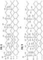
- FIGS. 7-8show perspective and flattened, unrolled views of the bare stent 202 having an inflow end 203, an outflow end 205, and four rows (I-IV) of struts 214, 216, 218, 222 (instead of five rows as shown in FIGS. 1-5 ).
- the fourth row IV of angled struts 222can be connected to the third row IV of angled struts 218 by a plurality of axially extending window frame portions 230 (which define commissure windows 220) and a plurality of axially extending struts 232.
- each window frame portion 230 and each axially extending strut 232can extend between the two rows of angled struts that are closest to the outflow end 205.
- each window frame portion 230can extend between a location 242 defined by the convergence of the upper ends of two angled struts 222 and a location 244 defined by the convergence of the upper ends of two angled struts 218.
- Each axially extending strut 232can extend between another location 246 defined by the convergence of the lower ends of two angled struts 222 and another location 248 defined by the convergence of the lower ends of two angled struts 218.
- the frame 202can comprise three window frame portions 230 spaced equally apart around the circumference of the frame 202. As shown, the frame 202 can be constructed to have six angled struts (along each of rows III and IV) between the window frame portions 230 along each row. The frame can be constructed to have three angled struts between each window frame portion 230 and the adjacent axial struts 232. Thus, each axial strut 232 can be located halfway between adjacent window frame portions 230, and the frame 200 can be constructed to integrate window frame portions and axially extending struts in a 1:1 ratio. In the illustrated embodiment, there are exactly three window frame portions 230 and exactly three axial struts 232.
- the frame 202can comprise, in sequence along the rows III and IV, a window frame portion 230 extending between a pair of locations 242, 244, followed by a pair of locations 246, 248 lacking an axially extending member, followed by a pair of locations 242, 244 lacking an axially extending member, followed by an axially extending strut 232 extending between a pair of locations 246, 248, followed by a pair of locations 242, 244 lacking an axially extending member, followed by a pair of locations 246, 248 lacking an axially extending member, followed by another window frame portion 230 extending between a pair of locations 242, 244 (and thus re-starting the sequence of window frame portions 230 and axially extending struts 232).
- the valve 200can cycle between open and closed states to permit or restrict the flow of blood.
- forces that pull the commissures radially inwards during cyclingcan also pull the window frame portions 230 radially inward to relieve stress on the leaflets during valve closure. Meanwhile, the axial struts 232 can be urged radially outward.
- the frame 200can be capable of assuming a collapsed configuration (such as for delivery on or within a catheter) and an expanded configuration (i.e ., functional configuration at the valve annulus).
- the plurality of axial strutsin the collapsed configuration, is positioned radially outwards relative to the leaflet attachment members and/or commissures.
- the valve 200in the process of transitioning from an expanded configuration to a collapsed configuration and/or from an collapsed configuration to an expanded configuration, the valve 200 can assume an intermediate configuration in which only those struts 222 of row IV that are adjacent to an axially extending strut 232 are brought together to extend axially (side-by-side and in substantial axial alignment with struts 232).
- a frame 302can have axial window frame members 330 extending between locations 342 defined by the convergence of the upper ends of two angled struts 322 and locations 344 defined by the convergence of the lower ends of two angled struts 318.
- the frame 302can have axially extending struts 332 extending between locations 346 defined by the convergence of the lower ends of two angled struts 322 and locations 348 defined by the convergence of the upper ends of two angled struts 318.
- Frame 302is similar to frame 202 except that the first three rows of angled struts (rows I, II, and III) are shifted 20 degrees relative to the same rows of frame 202.
- each window frame member 330is axially aligned with a location 344 defined by the convergence of the lower ends of two angled struts 318 of row III.
- Each window frame member 330can comprise a lower strut portion 334 below the level of the commissure window 320 (towards the inflow end of the stent 302).
- This lower strut portion 334extends from the lower end of a window frame member 330 to a location 344 defined by the convergence of the lower ends of two angled struts 318.
- the lower strut portion 334provides added length to the window frame member 330 and allows the frame member 330 to effectively bridge the larger distance between locations 342, 344 in this embodiment.
- Other features and components of frame 302can be similar to as described above for frame 202.
- FIG. 10shows a portion of a frame 402, according to another embodiment.
- the frame 402can have axial window frame members 430 extending between locations 442 defined by the convergence of the lower ends of two angled struts 422 and locations 444 defined by the convergence of the lower ends of two angled struts 418.
- the frame 402can have axially extending struts 432 extending between locations 446 defined by the convergence of the upper ends of two angled struts 422 and locations 448 defined by the convergence of the upper ends of two angled struts 418.
- the two upper rows of angled strutsincludes a total of three axial window frame members 430 and a total of three axially extending struts 432 located equidistant between the window frame members 430 with three angled struts 418 and three angled struts 422 extending between a window frame member 430 and an adjacent axially extending strut 432.
- the frame 402can also include three additional rows of angled struts located at the inflow end of the frame (not shown in FIG. 10 ), similar to embodiments discussed above.
- the lower end of each window frame member 430can be connected to the upper ends of two angled struts of an adjacent row (the third row from the outflow end of the frame) at a location 444.
- the lower end of each axially extending strut 432is not connected to any struts of the adjacent row.
- FIG. 11shows a portion of a frame 502, according to another embodiment.
- the frame 502can have axial window frame members 530 extending between locations 542 defined by the convergence of the lower ends of two angled struts 552 and locations 554 defined by the convergence of the upper ends of two angled struts 518.
- the frame 502can have axially extending struts 532 extending between locations 546 defined by the convergence of the upper ends of two angled struts 522 and locations 548 defined by the convergence of the lower ends of two angled struts 518.
- the axially extending struts 532 in this embodimentcan be longer than the window frame members 530 to account for the greater distance between locations 546, 548 compared to the distance between locations 542, 544.
- the two upper rows of angled strutsincludes a total of three axial window frame members 530 and a total of three axially extending struts 532 located equidistant between the window frame members 530 with three angled struts 518 and three angled struts 522 extending between a window frame member 530 and an adjacent axially extending strut 532.
- the frame 502can also include three additional rows of angled struts located at the inflow end of the frame (not shown in FIG. 11 ), similar to embodiments discussed above.
- each axially extending strut 532can be connected to the upper ends of two angled struts of an adjacent row (the third row from the outflow end of the frame) at a location 548.
- the lower end of each window frame member 530is not connected to any angled struts of the adjacent row.
- FIG. 12shows a portion of a frame 602, according to another embodiment.
- the frame 602can have axial window frame members 630 extending between locations 642 defined by the convergence of the upper ends of two angled struts 622 and locations 644 defined by the convergence of the upper ends of two angled struts 618.
- the frame 602can have axially extending struts 632 extending between locations 646 defined by the convergence of the lower ends of two angled struts 622 and locations 648 defined by the convergence of the lower ends of two angled struts 618.
- the two upper rows of angled strutsincludes a total of three axial window frame members 630 and a total of six axially extending struts 632.
- the frame 602can also include three additional rows of angled struts located at the inflow end of the frame (not shown in FIG. 12 ), similar to embodiments discussed above.
- the lower end of each axially extending strut 632can be connected to the upper ends of two angled struts of an adjacent row (the third row from the outflow end of the frame) at a location 648.
- the lower end of each window frame member 630is not connected to any struts of the adjacent row.
- FIG. 13shows a portion of a frame 702, according to another embodiment.
- the frame 702can have axial window frame members 730 extending between locations 742 defined by the convergence of the lower ends of two angled struts 722 and locations 744 defined by the convergence of the upper ends of two angled struts 718.
- the frame 702can have axially extending struts 732 extending between locations 746 defined by the convergence of the upper ends of two angled struts 722 and locations 748 defined by the convergence of the lower ends of two angled struts 718.
- the two upper rows of angled strutsincludes a total of three axial window frame members 730 and a total of six axially extending struts 732.
- struts 732can be longer than window frame members 730 to account for the greater distance between locations 746, 748 compared to the distance between locations 742, 744.
- the frame 702can also include three additional rows of angled struts located at the inflow end of the frame (not shown in FIG. 13 ), similar to embodiments discussed above.
- the lower end of each axially extending strut 732can be connected to the upper ends of two angled struts of an adjacent row (the third row from the outflow end of the frame) at a location 748.
- the lower end of each window frame member 730is not connected to any struts of the adjacent row.
- the prosthetic valve embodiments disclosed hereincan be surgically implanted and/or can be delivered using a delivery apparatus, such as a catheter.
- the prosthetic valvecan be mounted in a crimped state on or adjacent an inflatable balloon or equivalent expansion mechanism of the delivery apparatus.
- the delivery apparatus and crimped prosthetic valvecan be inserted into the patient's vasculature and advanced through the patient's body using known techniques.
- the prosthetic valveis delivered in a transfemoral procedure in which the delivery apparatus is inserted into a femoral artery and advanced through the aorta to the native aortic valve (or another native valve of the heart).
- the prosthetic valvecan be delivered in a transventricular procedure in which the delivery apparatus is inserted through a small surgical opening in the chest and another surgical opening in the wall of the heart, such as the wall of the left ventricle.
- the prosthetic valvecan be delivered in a transaortic procedure in which the delivery apparatus is inserted through a small surgical opening in the chest and another surgical opening in the ascending aorta, at a location above the aortic valve.
- the prosthetic valveis a replacement venous valve for implantation in a vein, or a replacement for another valve with a lower flow rate relative to the aortic valve.
- the balloon of the delivery apparatuscan be inflated to radially expand the prosthetic valve.
- the outer skirt of the prosthetic valvecan be forced into contact with the surrounding tissue of the native valve, establishing a seal between the outer surface of the frame and the surrounding tissue.
- the frame of the prosthetic valvewhen in the radially compressed, mounted configuration, can comprise an inflow end portion that has an outer diameter that is smaller than the outer diameter of the outflow end portion of the frame.
- the prosthetic valveWhen constructed of a self-expanding material, the prosthetic valve can be crimped to a radially compressed state and restrained in the compressed state by insertion into a sheath or equivalent mechanism of a delivery catheter. After the delivery apparatus is inserted into the body and advanced to position the prosthetic valve at the desired deployment location, the prosthetic valve can be advanced from the delivery sheath. As the prosthetic valve is deployed from the delivery sheath, the prosthetic valve can radially self-expand to its functional size.
- the prosthetic heart valvecan comprise commissure portions of the leaflets extending radially outwardly through corresponding window frame portions to locations outside of the frame and sutured to the side struts of the commissure window frame.
- the window frame portionscan be depressed radially inwardly relative to the surrounding portions of the frame, such as the frame portions extending between adjacent commissure windows, when the prosthetic valve is radially compressed to the collapsed configuration on a catheter.
- the commissure windows of the framecan be depressed inwardly a radial distance, such as between 0.2 mm and 1.0 mm, relative to the portions of the frame extending between adjacent commissure windows when the prosthetic valve is radially collapsed.
- the outer diameter of the outflow end portion the prosthetic valve comprising the commissure portionscan be generally consistent, as opposed to the commissure portions jutting outward from the surrounding portions of the prosthetic valve, which could hinder delivery of the prosthetic valve into the body.
- the outer diameter of the inflow end portion of the framecan still be smaller than, or about equal to, the outer diameter of the outflow end portion of the frame when the prosthetic valve is radially collapsed on the catheter, allowing for a minimal or reduced maximum overall diameter of the prosthetic valve.
- the diameter of a delivery catheter through which the prosthetic valve is advancedcan also be minimized or reduced. This allows the prosthetic valve to be delivered through smaller vessels in the body, making the delivery procedure less invasive, in general.
- the term “and/or” used between the last two of a list of elementsmeans any one or more of the listed elements.
- the phrase “A, B, and/or C”means “A”, “B”, “C”, “A and B”, “A and C", “B and C”, or "A, B, and C”.
Landscapes
- Health & Medical Sciences (AREA)
- Cardiology (AREA)
- Engineering & Computer Science (AREA)
- Biomedical Technology (AREA)
- Life Sciences & Earth Sciences (AREA)
- Transplantation (AREA)
- Heart & Thoracic Surgery (AREA)
- Vascular Medicine (AREA)
- Oral & Maxillofacial Surgery (AREA)
- Animal Behavior & Ethology (AREA)
- General Health & Medical Sciences (AREA)
- Public Health (AREA)
- Veterinary Medicine (AREA)
- Prostheses (AREA)
- Biological Depolymerization Polymers (AREA)
- Chair Legs, Seat Parts, And Backrests (AREA)
Description
- This disclosure is in the field of prosthetic heart valves, stents for use with prosthetic heart valves
- Existing frames for prosthetic heart valves typically comprise rows of angled struts and a plurality of axial frame members spaced apart around the circumference of the frame. The plurality of axial frame members may comprise a plurality of leaflet attachment members (for attaching to the commissures of the supported valvular structure) and a multitude of axially directed struts extending between the rows of angled struts. A frame usually has three or more axially directed struts for every leaflet attachment member, and generally has no more than two angled struts located in between adjacent struts or other axial frame members. Indeed, having a large number of axially directed struts is perceived to be necessary for preserving the structural stability of the stent and/or valve. Unfortunately, having a large number of axial struts can come at the expense of valve flexibility.
US 2006/0122693 A1 discloses a stent valve that includes a scaffold, the scaffold including interlinked struts, the scaffold having a scaffold passageway extending substantially longitudinally therethrough. Axial struts members connect second and third rows of angled struts, counted from an outflow end. The stent valve also includes a valve leaflet extending at least partially across the scaffold passageway, the valve leaflet defining a leaflet periphery. At least a portion of the leaflet periphery extends integrally from at least a portion of at least one of the struts and at least a portion of the leaflet periphery is substantially parallel to the at least a portion of said at least one of said struts.- A need therefore exists for stents and prosthetic valves that can have a high degree of flexibility, without compromising mechanical integrity or function.
US8133270 B2 discloses a heart valve prosthesis having an expandable frame comprising a hollow portion, a proximal end, and distal end.- According to the present invention, a prosthetic device in accordance with claim 1 is provided. Further advantageous embodiments of the prosthetic device are defined in the dependent claims.
- In one aspect of the disclosure, a prosthetic device for implantation at a cardiac valve annulus has an annular frame with an inflow end, an outflow end, and a plurality of axial frame members bridging two circumferentially extending rows of angled struts, wherein the plurality of axial frame members comprises a plurality of axially extending leaflet attachment members and a plurality of axial struts in a 1:1 ratio.
- In some embodiments, the device can further comprise a leaflet structure positioned within the frame, the leaflet structure having a plurality of commissures that are secured to the frame at the leaflet attachment members.
- In some embodiments, at least three angled struts separate adjacent axial frame members along each of the two rows of angled struts.
- In some embodiments, exactly six angled struts separate adjacent leaflet attachment members along each of the two rows of angled struts, and exactly three angled struts separate adjacent axial frame members along each of the two rows of angled struts, such that each axial strut is positioned halfway between adjacent leaflet attachment members.
- In some embodiments, each axial frame member extends between locations defined by the convergence of adjacent angled struts.
- In some embodiments, the device further comprises an inner skirt secured to an interior portion of the annular frame, and an outer skirt secured to an exterior portion of the annular frame.
- In some embodiments, the frame comprises exactly four rows of angled struts.
- In some embodiments, the valve member comprises exactly three leaflets arranged in a tricuspid configuration, wherein the frame comprises exactly three axial struts and exactly three leaflet attachment members, and wherein the exactly three angled struts separate adjacent axial frame members along each of the two rows of angled struts.
- In another aspect of the disclosure, an annular frame for a prosthetic heart valve can comprise an inflow end, an outflow end, and a plurality of axial frame members spaced angularly around the circumference of the frame. The plurality of axial frame members can bridge two circumferentially extending rows of angled struts, wherein each of the two rows comprise at least three angled struts between adjacent axial frame members.
- In some embodiments, each of the two rows comprises exactly three angled struts between adjacent axial frame members.
- In some embodiments, the plurality of axial frame members comprises a plurality of axially extending leaflet attachment members, and each of the two rows comprises exactly six angled struts between adjacent leaflet attachment members.
- In some embodiments, the plurality of axial frame members comprises a plurality of axially extending leaflet attachment members, wherein each of the two rows comprises four angled struts between adjacent axial frame members and eight angled struts between adjacent leaflet attachment members.
- In some embodiments, the plurality of axial frame members comprises exactly three leaflet attachment members and exactly three axial struts.
- In some embodiments, the leaflet attachment members extend between locations defined by the convergence of the upper ends of adj acent angled struts of each row of angled struts, and the axial struts extend between locations defined by the convergence of the lower ends of adjacent angled struts of each row of angled struts.
- In some embodiments, the two rows of angled struts can comprise a first row and a second row, wherein the first row is closer to the outflow end than the second row.
- In some embodiments, the leaflet attachment members extend from locations defined by the convergence of the upper ends of adj acent angled struts along the first row of angled struts to locations defined by the convergence of the lower ends of adjacent angled struts along the second row of angled struts, and the axial struts extend between locations defined by the convergence of the lower ends of adjacent angled struts along the first row of angled struts to locations defined by the convergence of upper ends of adjacent angled struts along the second row of angled struts.
- In some embodiments, the leaflet attachment members extend from locations defined by the convergence of the upper ends of adjacent angled struts along the first row of angled struts to locations defined by the convergence of the upper ends of adjacent angled struts along the second row of angled struts, and the axial struts extend between locations defined by the convergence of the lower ends of adjacent angled struts along the first row of angled struts to locations defined by the convergence of lower ends of adjacent angled struts along the second row of angled struts.
- In some embodiments, the frame comprises exactly four rows of angled struts.
- In another aspect of the disclosure, a prosthetic device for implantation at a cardiac valve annulus is provided, comprising an annular frame having an inflow end, an outflow end, at least four rows of circumferentially extending angled struts, and exactly six axial frame members bridging two rows of the four rows of circumferentially extending angled struts. The plurality of axial frame members can comprise exactly three axially extending leaflet attachment members and exactly three axial struts, wherein each of the two rows comprises exactly three angled struts between each adjacent pair of a leaflet attachment member and an axial strut, and exactly six angled struts between adjacent leaflet attachment members. The device can further comprise a tri-leaflet valve member positioned within the frame having commissures that are secured to the frame at the leaflet attachment members.
- The foregoing and other objects, features, and advantages of the invention will become more apparent from the following detailed description, which proceeds with reference to the accompanying figures.
FIGS. 1 and 2 show side and perspective views of an exemplary embodiment of a prosthetic heart valve.FIGS. 3-5 show side, perspective, and flattened views of an exemplary frame of the prosthetic heart valve ofFIG. 1 .FIG. 6 is a perspective view of another exemplary prosthetic heart valve.FIGS. 7-8 show perspective and flattened views of an exemplary frame of the prosthetic heart valve ofFIG. 6 .FIG. 9 shows a flattened view of another exemplary frame for a prosthetic heart valve.FIG. 10 shows a flattened view of a portion of another exemplary frame for a prosthetic heart valve.FIG. 11 shows a flattened view of a portion of another exemplary frame for a prosthetic heart valve.FIG. 12 shows a flattened view of a portion of another exemplary frame for a prosthetic heart valve.FIG. 13 shows a flattened view of a portion of another exemplary frame for a prosthetic heart valve.- Disclosed herein are prosthetic heart valves and stents for use with such valves that are capable of a high degree of flexibility. This flexibility can be useful for delivery to the valve annulus (such as for crimping/expanding a transcatheter heart valve (THV)) and/or for accommodating movement of the valve during cardiac cycling. In particular embodiments, strategically selected locations around the circumference of the frame are without axial struts, resulting in the improved flexibility. In various embodiments, the flexibility of the commissures is enhanced as a result of an increase in the distance between each commissure and the nearest axial frame member (other than any support member located at the commissure such as a commissure support or window frame member). The frame can have one or more circumferentially extending rows of struts with three continuous angled struts between one or more pairs of axial supports. In some embodiments, these one or more rows of struts are located towards an outflow end of the frame. In some embodiments, the frame can have two rows of circumferentially extending struts (towards the outflow end of the valve) having three continuous angled struts between pairs of axial supports. In some embodiments, the frame has three continuous angled struts separating each commissure support (located at each commissure) from the nearest axial support. In another embodiment, there are four such angled struts separating each commissure support from the nearest axial strut.
- As used herein, an "axial support" is a junction where at least three struts are connected, such as two angled struts connecting to a single axial strut or a junction of two angled struts and another axial member such as a commissure support. As used herein, an "axial frame member" is any axially extending support member that connects two (or more) circumferentially extending rows of angled struts. Thus, an axial frame member can be an axial support member that engages one or more leaflets, such as a commissure support. An axial frame member can also be a simple axial strut or other axial member that does not engage a leaflet. As used herein, a "commissure support" (also referred to as a "leaflet attachment member") is an axially extending support member configured to support a respective commissure of a prosthetic valve member. A commissure support can be a commissure "window frame member" configured to receive a commissure of a prosthetic valve member through an opening in the frame member, as further described below. A commissure support can also be an axial strut or other axial support member that does not include a window or other opening sized to receive a commissure. As such, a commissure can be supported by a leaflet attachment member using various techniques or mechanisms, such as by securing commissures to respective leaflet attachment members with sutures extending through suture openings in the leaflet attachment members.
FIGS. 1-2 show aprosthetic heart valve 100, according to one embodiment in side view and in perspective, respectively. The illustrated prosthetic valve is adapted to be implanted in the native aortic annulus, although in other embodiments it can be adapted to be implanted in the other native annuluses of the heart (i.e., the native mitral, pulmonary, and tricuspid valves) or in other tubular passageways in the body. Thevalve 100 can have four main components: a stent orframe 102, avalvular structure 104, aninner skirt 106, and anouter skirt 108. Theframe 102 can have aninflow end 103 and anoutflow end 105.- The
valvular structure 104 can comprise threeleaflets 110, collectively forming a leaflet structure, which can be arranged to collapse in a tricuspid arrangement. Theleaflets 110 can be secured to one another at their adjacent sides to form commissures. Theleaflets 110 can be formed of pericardial tissue (e.g., bovine pericardial tissue), biocompatible synthetic materials, or various other suitable natural or synthetic materials as known in the art and described inU.S. Pat. No. 6,730,118 . - The
bare frame 102 is shown inFIGS. 3-5 in a side view, a perspective view, and an unrolled and flattened configuration, respectively. Theframe 102 can be formed with a plurality of circumferentially spaced slots, or commissure windows 120 (three in the illustrated embodiment), that are adapted to mount the commissures of thevalvular structure 104 to the frame, as described in greater detail below. Theframe 102 can be made of any of various suitable plastically-expandable materials (e.g., stainless steel,etc.) or self-expanding materials (e.g., nitinol) as known in the art. - Suitable plastically-expandable materials that can be used to form the
frame 102 can include, without limitation, stainless steel, a nickel based alloy (e.g., a cobalt-chromium or a nickel-cobalt-chromium alloy), polymers, or combinations thereof. In particular embodiments, theframe 102 can be made of a nickel-cobalt-chromium-molybdenum alloy, such as MP35N® alloy (SPS Technologies), which is equivalent to UNS R30035 alloy (covered by ASTM F562-02). MP35NO/UNS R30035 alloy comprises 35% nickel, 35% cobalt, 20% chromium, and 10% molybdenum, by weight. It has been found that the use of MP35N® alloy to form theframe 102 can provide superior structural results over stainless steel. In particular, when MP35N® alloy is used as the frame material, less material is needed to achieve the same or better performance in radial and crush force resistance, fatigue resistances, and corrosion resistance. Moreover, since less material is required, the crimped profile of theframe 102 can be reduced, thereby providing a lower profile valve assembly for percutaneous delivery to the treatment location in the body. - When constructed of a plastically-expandable material, the frame 102 (and thus the valve 10) can be crimped to a radially compressed state on a delivery catheter and then expanded inside a patient by an inflatable balloon or equivalent expansion mechanism. When constructed of a self-expandable material, the frame 102 (and thus the valve 100) can be crimped to a radially compressed state and restrained in the compressed state by insertion into a sheath or equivalent mechanism of a delivery catheter. Once inside the body, the valve can be advanced from the delivery sheath, which allows the valve to expand to its functional size.
- Referring to
FIG. 5 , the frame 102 (shown in a flattened configuration) in the illustrated embodiment comprises a first, lower row I ofangled struts 112 arranged end-to-end and extending circumferentially at the inflow end of the frame; a second row II of circumferentially extending,angled struts 114; a third row III of circumferentially extending,angled struts 116; a fourth row IV of circumferentially extending,angled struts 118; and a fifth row V of circumferentially extending,angled struts 122 at theoutflow end 105. A plurality of substantially straight, axially extendingstruts 124 can be used to interconnect thestruts 112 of the first row I with thestruts 114 of the second row II. The fifth row V ofangled struts 122 are connected to the fourth row IV ofangled struts 118 by a plurality of axially extending window frame portions 130 (which define the commissure windows 120) and a plurality of axially extendingstruts 132. - Each commissure
window frame portion 130 mounts a respective commissure of thevalvular structure 104. As can be seen, eachwindow frame portion 130 is secured at its upper and lower ends to the adjacent rows of angled struts to provide a robust configuration that enhances fatigue resistance under cyclic loading of the valve compared with known frames using cantilevered struts for supporting the commissures of the leaflet structure. This configuration enables a reduction in the frame wall thickness to achieve a smaller crimped diameter of the valve. In particular embodiments, the thickness of the frame 12 as measured between the inner diameter and outer diameter is about 0.48 mm or less. - As best shown in
FIGS. 3-4 , the struts and frame portions of the frame collectively define a plurality of open cells of the frame. At the inflow end of theframe 102, struts 112, struts 114, and struts 134 define a lower row ofcells defining openings 136. The second, third, and fourth rows ofstruts cells defining openings 138. The fourth and fifth rows ofstruts window frame portions 130 and struts 132, define an upper row ofcells defining openings 140. Theopenings 140 are relatively large and are sized to allow portions of thevalvular structure 104 to protrude, or bulge, into and/or through theopenings 140 when theframe 102 is crimped in order to minimize the crimping profile. - In some embodiments, there are fewer than three axially extending
struts 132 between adjacentwindow frame portions 130, along the length of the rows, such as only two axially extendingstruts 132 or only one axially extendingstrut 132. In some embodiments, there is only one axially extendingstrut 132 in between adjacentwindow frame portions 130, which can be located halfway in between thewindow frame portions 130. Thus, in various embodiments, the frame can be specifically constructed to integratewindow frame portions 130 and axially extendingstruts 132 in a 1:1 ratio. - In one embodiment illustrated in
FIGS. 3-5 , there are exactly threewindow frame portions 130 and exactly threeaxial struts 132. Minimizing or reducing the number of axially extendingstruts 132 betweenwindow frame portions 130 promotes more compact crimping of the prosthetic valve. This also maximizes or increases the size ofopenings 140, which, for example, is advantageous in cases where theoutflow end 105 of the prosthetic valve extends higher than the level of the coronary ostia. In such cases, thelarger openings 140 can provide access to the coronary arteries for future procedures, such as procedures requiring catheterization of the coronary arteries. - Each
window frame portion 130 and/or each axially extendingstrut 132 can each extend betweenlocations 142 characterized by the convergence of the lower ends of two angled struts 122 (of row V, at the outflow end 105) to locations ornodes 144 defined by the convergence of the upper ends of two angled struts 118 (of row IV). There can be twoangled struts 122 along row V from onelocation 142 to thenext location 142, and twoangled struts 118 along row IV from onelocation 144 to thenext location 144. - The
frame 102 can comprise an axially extending frame member (i.e., aframe portion 130 or a strut 132) at every other such pair ofsuch locations frame 102 can have awindow frame portion 130 every four such locations, and spaced equally apart around the circumference of theframe 102, which can provide for a total of three window frame portions 130 (corresponding to the three commissures in a tri-leaflet valve). Thus, theframe 102 can comprise, in sequence along the row V, awindow frame portion 130 extending between a pair ofsuch locations locations axially extending strut 132 extending between a third pair oflocations locations window frame portion 130 extending between a pair ofsuch locations 142, 144 (and thus re-starting the sequence of struts and frame portions). With two angled struts (along each of rows IV and V) between each set oflocations window frame portions 130, along each row, with four continuous angled struts between eachwindow frame portion 130 and its adjacent axial struts 132 (i.e., no other axial frame members in between). - After the
prosthetic heart valve 100 is properly implanted at the valve annulus, theprosthetic valve 100 can cycle between open and closed states to permit or restrict the flow of blood. In various embodiments, theframe 102 of theprosthetic heart valve 100 provides a measure of damping during valve closure by bending inwards during diastole, which relieves stress on the leaflets. For example, forces that pull the commissures of theleaflets 110 radially inwards (such as during valve closure) can also pull areas of the frame immediately adjacent the commissures (such as the window frame portions 130) radially inward, while theaxial struts 132 can be urged radially outward. In various embodiments, this damping effect (including pulling of theframe portions 130 radially inward and pushing of theaxial struts 132 radially outward) is enhanced by reducing the number of axial struts present along the top rungs (between rows IV and V in valve 100) as disclosed herein, relative to frames having a greater number of axial frame members (e.g., greater number of axial struts). - The main functions of the
inner skirt 106 are to assist in securing thevalvular structure 104 to theframe 102 and to assist in forming a good seal between thevalve 100 and the native annulus by blocking the flow of blood through the open cells of theframe 102 below the lower edge of theleaflets 110. Theinner skirt 106 desirably comprises a tough, tear resistant material such as polyethylene terephthalate (PET), although various other synthetic or natural materials can be used. Theinner skirt 106 can be secured to the inside of theframe 102 via sutures. Thevalvular structure 104 can be attached to theinner skirt 106 with the assistance of one or more thin PET reinforcing strips (which collectively can form a sleeve, not pictured), which can enable secure suturing and protect the pericardial tissue of the leaflet structure from tearing. Thevalvular structure 104 can be sandwiched between theinner skirt 106 and the thin PET strips. - The upper edge portion of the
inner skirt 106 can be formed with a plurality of projections that define an undulating shape that generally follows the shape of the fourth row of struts 118 (row IV) immediately adjacent the lower ends ofaxial struts 132. In this manner, as best shown inFIG. 1 , the upper edge ofinner skirt 106 can be tightly secured tostruts 118 withsuture 146. Theinner skirt 106 can also be secured to the first, second, and/or third rows ofstruts suture 146. - The
inner skirt 106 can be sutured to theframe 102 at locations away from the suture line attaching the lower edges of theleaflets 110 to theinner skirt 106, which both reduces concentration of stress at the leaflet-suture-line and increases pliability to the skirt in that area. - As shown in
FIGS. 1-2 , a plurality offlexible connectors 125 can be used to interconnect each pair of adjacent edges of theleaflets 110 and to mount theleaflets 110 to the commissurewindow frame portions 130. Theflexible connectors 125 can be made from a piece of woven PET fabric, although other synthetic and/or natural materials can be used. Each commissure can comprise two tab portions of two adjacent leaflets. Each commissure can be secured to the frame, for example, by inserting the tab portions through thecommissure windows 120 of thewindow frame portions 130, and suturing the tab portions to aconnector 125 outside of theframe 102. - The
outer skirt 108 can be laser cut or otherwise formed from a strong, durable piece of material, such as woven PET, although other synthetic or natural materials can be used. Theouter skirt 108 can have a substantially straight lower edge and an upper edge defining a plurality of alternatingprojections 150 andnotches 152. The lower edge of theouter skirt 108 can be sutured to the lower edge of theinner skirt 106 at the inflow end of thevalve 100. In other embodiments, theinner skirt 106 andouter skirt 108 are integrally manufactured as a single component. As shown inFIGS. 1-2 , eachprojection 150 can be affixed to the second rung II ofstruts 114 of theframe 102 withsutures 154. - Additional details relevant to the securing of the
valve member 104,inner skirt 106 andouter skirt 108 to theframe 102 are provided inU.S. Patent Publication 2011/0123529 . - In various embodiments, a frame can be constructed to have greater or fewer rows of angled struts than in
frame 102, such as four or six rows of angled struts. In various other frame embodiments, each window frame portion and/or each axially extending strut can extend between two locations each defined by the convergence of the upper ends of angled struts. In various embodiments, each window frame portion and/or each axially extending strut can extend between two locations each defined by the convergence of the lower ends of angled struts. FIG. 6 shows a perspective view of another exemplaryprosthetic valve 200 with aninner skirt 206, anouter skirt 208, and avalve member 204 mounted within astent 202. Thevalve member 204 can have a set of threeleaflets 210. A plurality offlexible connectors 225 can be used to interconnect pairs of adj acent edges of theleaflets 210 and to mount theleaflets 210 to the commissurewindow frame portions 230.FIGS. 7-8 show perspective and flattened, unrolled views of thebare stent 202 having aninflow end 203, anoutflow end 205, and four rows (I-IV) ofstruts FIGS. 1-5 ). The fourth row IV ofangled struts 222 can be connected to the third row IV ofangled struts 218 by a plurality of axially extending window frame portions 230 (which define commissure windows 220) and a plurality of axially extendingstruts 232.- Thus, each
window frame portion 230 and eachaxially extending strut 232 can extend between the two rows of angled struts that are closest to theoutflow end 205. In particular, eachwindow frame portion 230 can extend between alocation 242 defined by the convergence of the upper ends of twoangled struts 222 and alocation 244 defined by the convergence of the upper ends of twoangled struts 218. Each axially extendingstrut 232 can extend between anotherlocation 246 defined by the convergence of the lower ends of twoangled struts 222 and anotherlocation 248 defined by the convergence of the lower ends of twoangled struts 218. - The
frame 202 can comprise threewindow frame portions 230 spaced equally apart around the circumference of theframe 202. As shown, theframe 202 can be constructed to have six angled struts (along each of rows III and IV) between thewindow frame portions 230 along each row. The frame can be constructed to have three angled struts between eachwindow frame portion 230 and the adjacent axial struts 232. Thus, eachaxial strut 232 can be located halfway between adjacentwindow frame portions 230, and theframe 200 can be constructed to integrate window frame portions and axially extending struts in a 1:1 ratio. In the illustrated embodiment, there are exactly threewindow frame portions 230 and exactly threeaxial struts 232. - In particular, the
frame 202 can comprise, in sequence along the rows III and IV, awindow frame portion 230 extending between a pair oflocations locations locations axially extending strut 232 extending between a pair oflocations locations locations window frame portion 230 extending between a pair oflocations 242, 244 (and thus re-starting the sequence ofwindow frame portions 230 and axially extending struts 232). - Once the
prosthetic heart valve 200 is properly installed at the valve annulus, thevalve 200 can cycle between open and closed states to permit or restrict the flow of blood. As discussed with respect toprosthetic valve 100, forces that pull the commissures radially inwards during cycling can also pull thewindow frame portions 230 radially inward to relieve stress on the leaflets during valve closure. Meanwhile, theaxial struts 232 can be urged radially outward. - The
frame 200 can be capable of assuming a collapsed configuration (such as for delivery on or within a catheter) and an expanded configuration (i.e., functional configuration at the valve annulus). In various embodiments, in the collapsed configuration, the plurality of axial struts is positioned radially outwards relative to the leaflet attachment members and/or commissures. In one embodiment, in the process of transitioning from an expanded configuration to a collapsed configuration and/or from an collapsed configuration to an expanded configuration, thevalve 200 can assume an intermediate configuration in which only thosestruts 222 of row IV that are adjacent to anaxially extending strut 232 are brought together to extend axially (side-by-side and in substantial axial alignment with struts 232). - In another embodiment, as shown in
FIG. 9 , aframe 302 can have axialwindow frame members 330 extending betweenlocations 342 defined by the convergence of the upper ends of twoangled struts 322 andlocations 344 defined by the convergence of the lower ends of twoangled struts 318. Theframe 302 can have axially extendingstruts 332 extending betweenlocations 346 defined by the convergence of the lower ends of twoangled struts 322 andlocations 348 defined by the convergence of the upper ends of twoangled struts 318. Frame 302 is similar to frame 202 except that the first three rows of angled struts (rows I, II, and III) are shifted 20 degrees relative to the same rows offrame 202. Thus, eachwindow frame member 330 is axially aligned with alocation 344 defined by the convergence of the lower ends of twoangled struts 318 of row III. Eachwindow frame member 330 can comprise alower strut portion 334 below the level of the commissure window 320 (towards the inflow end of the stent 302). Thislower strut portion 334 extends from the lower end of awindow frame member 330 to alocation 344 defined by the convergence of the lower ends of twoangled struts 318. Thelower strut portion 334 provides added length to thewindow frame member 330 and allows theframe member 330 to effectively bridge the larger distance betweenlocations frame 302 can be similar to as described above forframe 202.FIG. 10 shows a portion of aframe 402, according to another embodiment. InFIG. 10 , only one-third of the circumference of the two upper rows of angled struts (the rows closest to the outflow end) is shown. Theframe 402 can have axialwindow frame members 430 extending betweenlocations 442 defined by the convergence of the lower ends of twoangled struts 422 andlocations 444 defined by the convergence of the lower ends of twoangled struts 418. Theframe 402 can have axially extendingstruts 432 extending betweenlocations 446 defined by the convergence of the upper ends of twoangled struts 422 andlocations 448 defined by the convergence of the upper ends of twoangled struts 418.- The two upper rows of angled struts includes a total of three axial
window frame members 430 and a total of three axially extendingstruts 432 located equidistant between thewindow frame members 430 with threeangled struts 418 and threeangled struts 422 extending between awindow frame member 430 and an adjacentaxially extending strut 432. Theframe 402 can also include three additional rows of angled struts located at the inflow end of the frame (not shown inFIG. 10 ), similar to embodiments discussed above. The lower end of eachwindow frame member 430 can be connected to the upper ends of two angled struts of an adjacent row (the third row from the outflow end of the frame) at alocation 444. Thus, in this embodiment, the lower end of eachaxially extending strut 432 is not connected to any struts of the adjacent row. FIG. 11 shows a portion of aframe 502, according to another embodiment. InFIG. 11 , only one-third of the circumference two upper rows of angled struts (the rows closest to the outflow end) are shown. Theframe 502 can have axialwindow frame members 530 extending between locations 542 defined by the convergence of the lower ends of twoangled struts 552 and locations 554 defined by the convergence of the upper ends of twoangled struts 518. Theframe 502 can have axially extendingstruts 532 extending betweenlocations 546 defined by the convergence of the upper ends of twoangled struts 522 andlocations 548 defined by the convergence of the lower ends of twoangled struts 518. Theaxially extending struts 532 in this embodiment can be longer than thewindow frame members 530 to account for the greater distance betweenlocations locations 542, 544.- The two upper rows of angled struts includes a total of three axial
window frame members 530 and a total of three axially extendingstruts 532 located equidistant between thewindow frame members 530 with threeangled struts 518 and threeangled struts 522 extending between awindow frame member 530 and an adjacentaxially extending strut 532. Theframe 502 can also include three additional rows of angled struts located at the inflow end of the frame (not shown inFIG. 11 ), similar to embodiments discussed above. The lower end of eachaxially extending strut 532 can be connected to the upper ends of two angled struts of an adjacent row (the third row from the outflow end of the frame) at alocation 548. Thus, in this embodiment, the lower end of eachwindow frame member 530 is not connected to any angled struts of the adjacent row. FIG. 12 shows a portion of aframe 602, according to another embodiment. InFIG. 12 , only one-third of the circumference of the two upper rows of angled struts (the rows closest to the outflow end) is shown. Theframe 602 can have axialwindow frame members 630 extending betweenlocations 642 defined by the convergence of the upper ends of twoangled struts 622 andlocations 644 defined by the convergence of the upper ends of twoangled struts 618. Theframe 602 can have axially extendingstruts 632 extending betweenlocations 646 defined by the convergence of the lower ends of twoangled struts 622 andlocations 648 defined by the convergence of the lower ends of twoangled struts 618.- In the embodiment of
FIG. 12 , there are two suchaxially extending struts 632 spaced between each pair ofwindow frame members 630. In particular, for each pair of window frame members, there are three angles struts 618 and three angles struts 622 between eachwindow frame member 630 and the closestaxially extending strut 632, and two angles struts 618 and two angles struts 622 between the two axially extendingstruts 632. Thus, for theentire frame 602, the two upper rows of angled struts includes a total of three axialwindow frame members 630 and a total of six axially extendingstruts 632. - The
frame 602 can also include three additional rows of angled struts located at the inflow end of the frame (not shown inFIG. 12 ), similar to embodiments discussed above. The lower end of eachaxially extending strut 632 can be connected to the upper ends of two angled struts of an adjacent row (the third row from the outflow end of the frame) at alocation 648. Thus, in this embodiment, the lower end of eachwindow frame member 630 is not connected to any struts of the adjacent row. FIG. 13 shows a portion of aframe 702, according to another embodiment. InFIG. 13 , only one-third of the circumference of the two upper rows of angled struts (the rows closest to the outflow end) is shown. Theframe 702 can have axialwindow frame members 730 extending betweenlocations 742 defined by the convergence of the lower ends of twoangled struts 722 andlocations 744 defined by the convergence of the upper ends of twoangled struts 718. Theframe 702 can have axially extendingstruts 732 extending betweenlocations 746 defined by the convergence of the upper ends of twoangled struts 722 andlocations 748 defined by the convergence of the lower ends of twoangled struts 718.- In the embodiment of
FIG. 13 , there are two suchaxially extending struts 732 spaced between each pair ofwindow frame members 730. In particular, for each pair of window frame members, there are three angles struts 718 and three angles struts 722 between eachwindow frame member 730 and the closestaxially extending strut 732, and two angles struts 718 and two angles struts 722 between the two axially extendingstruts 732. Thus, for theentire frame 702, the two upper rows of angled struts includes a total of three axialwindow frame members 730 and a total of six axially extendingstruts 732. Also, struts 732 can be longer thanwindow frame members 730 to account for the greater distance betweenlocations locations - The
frame 702 can also include three additional rows of angled struts located at the inflow end of the frame (not shown inFIG. 13 ), similar to embodiments discussed above. The lower end of eachaxially extending strut 732 can be connected to the upper ends of two angled struts of an adjacent row (the third row from the outflow end of the frame) at alocation 748. Thus, in this embodiment, the lower end of eachwindow frame member 730 is not connected to any struts of the adjacent row. - The prosthetic valve embodiments disclosed herein can be surgically implanted and/or can be delivered using a delivery apparatus, such as a catheter. The prosthetic valve can be mounted in a crimped state on or adjacent an inflatable balloon or equivalent expansion mechanism of the delivery apparatus. The delivery apparatus and crimped prosthetic valve can be inserted into the patient's vasculature and advanced through the patient's body using known techniques.
- In one implementation, the prosthetic valve is delivered in a transfemoral procedure in which the delivery apparatus is inserted into a femoral artery and advanced through the aorta to the native aortic valve (or another native valve of the heart). In another implementation, the prosthetic valve can be delivered in a transventricular procedure in which the delivery apparatus is inserted through a small surgical opening in the chest and another surgical opening in the wall of the heart, such as the wall of the left ventricle. In another implementation, the prosthetic valve can be delivered in a transaortic procedure in which the delivery apparatus is inserted through a small surgical opening in the chest and another surgical opening in the ascending aorta, at a location above the aortic valve. In another implementation, the prosthetic valve is a replacement venous valve for implantation in a vein, or a replacement for another valve with a lower flow rate relative to the aortic valve.
- When the prosthetic valve is positioned at the desired deployment location (e.g., within the native aortic valve), the balloon of the delivery apparatus can be inflated to radially expand the prosthetic valve. In some embodiments, upon full expansion of the prosthetic valve, the outer skirt of the prosthetic valve can be forced into contact with the surrounding tissue of the native valve, establishing a seal between the outer surface of the frame and the surrounding tissue. The frame of the prosthetic valve, when in the radially compressed, mounted configuration, can comprise an inflow end portion that has an outer diameter that is smaller than the outer diameter of the outflow end portion of the frame.
- When constructed of a self-expanding material, the prosthetic valve can be crimped to a radially compressed state and restrained in the compressed state by insertion into a sheath or equivalent mechanism of a delivery catheter. After the delivery apparatus is inserted into the body and advanced to position the prosthetic valve at the desired deployment location, the prosthetic valve can be advanced from the delivery sheath. As the prosthetic valve is deployed from the delivery sheath, the prosthetic valve can radially self-expand to its functional size.
- The prosthetic heart valve can comprise commissure portions of the leaflets extending radially outwardly through corresponding window frame portions to locations outside of the frame and sutured to the side struts of the commissure window frame. To minimize the crimp profile of the prosthetic valve, the window frame portions can be depressed radially inwardly relative to the surrounding portions of the frame, such as the frame portions extending between adjacent commissure windows, when the prosthetic valve is radially compressed to the collapsed configuration on a catheter.
- For example, the commissure windows of the frame can be depressed inwardly a radial distance, such as between 0.2 mm and 1.0 mm, relative to the portions of the frame extending between adjacent commissure windows when the prosthetic valve is radially collapsed. In this way, the outer diameter of the outflow end portion the prosthetic valve comprising the commissure portions can be generally consistent, as opposed to the commissure portions jutting outward from the surrounding portions of the prosthetic valve, which could hinder delivery of the prosthetic valve into the body. Even with the radially depressed commissure window frames, the outer diameter of the inflow end portion of the frame can still be smaller than, or about equal to, the outer diameter of the outflow end portion of the frame when the prosthetic valve is radially collapsed on the catheter, allowing for a minimal or reduced maximum overall diameter of the prosthetic valve. By minimizing or reducing the diameter of the prosthetic valve when mounted on the delivery catheter, the diameter of a delivery catheter through which the prosthetic valve is advanced can also be minimized or reduced. This allows the prosthetic valve to be delivered through smaller vessels in the body, making the delivery procedure less invasive, in general.
- Additional details relevant to delivery of the prosthetic heart valves are provided in
U.S. Patent Publication 2011/0123529 . - For purposes of this description, certain aspects, advantages, and novel features of the embodiments of this disclosure are described herein. The disclosed methods, apparatuses, and systems should not be construed as limiting in any way. Instead, the present disclosure is directed toward all novel and nonobvious features and aspects of the various disclosed embodiments, alone and in various combinations and sub-combinations with one another. The methods, apparatuses, and systems are not limited to any specific aspect or feature or combination thereof, nor do the disclosed embodiments require that any one or more specific advantages be present or problems be solved.
- Although the operations of some of the disclosed methods are described in a particular, sequential order for convenient presentation, it should be understood that this manner of description encompasses rearrangement, unless a particular ordering is required by specific language. For example, operations described sequentially may in some cases be rearranged or performed concurrently. Moreover, for the sake of simplicity, the attached drawings may not show the various ways in which the disclosed methods can be used in conjunction with other methods. As used herein, the terms "a", "an", and "at least one" encompass one or more of the specified element. That is, if two of a particular element are present, one of these elements is also present and thus "an" element is present. The terms "a plurality of" and "plural" mean two or more of the specified element.
- As used herein, the term "and/or" used between the last two of a list of elements means any one or more of the listed elements. For example, the phrase "A, B, and/or C" means "A", "B", "C", "A and B", "A and C", "B and C", or "A, B, and C".
- In view of the many possible embodiments to which the principles of the disclosed invention may be applied, it should be recognized that the illustrated embodiments are only preferred examples of the invention and should not be taken as limiting the scope of the invention. Rather, the scope of the invention is defined by the following claims. I therefore claim as my invention all that comes within the scope of these claims.
Claims (13)
- A prosthetic device (100; 200) for implantation at a cardiac valve annulus, the prosthetic device (100; 200) having a radially compressed state and an expanded state and comprising:an annular frame (302) having an inflow end (103; 203), an outflow end (105; 205), at least four rows of circumferentially extending angled struts (314, 316, 318, 322), and a plurality of axial frame members (330, 332, 334) bridging two of the at least four rows of angled struts, wherein the plurality of axial frame members comprises a plurality of axially extending leaflet attachment members (330, 334) and a plurality of axial struts (332) in a 1:1 ratio,the prosthetic device (100; 200) further comprising a leaflet structure (104; 204) positioned within the frame (302) during the compressed state and the expanded state of the prosthetic device, the leaflet structure (104; 204) having a plurality of commissures that are secured to the frame (302) at the leaflet attachment members (330),wherein the two rows of angled struts (318, 322) bridged by the plurality of axial frame members (330, 332, 334) comprise a first row (322) and a second row (318), whereinthe first row (322) is closer to the outflow end (105; 205) than the second and the other rows of the at least four rows, and whereinthe axial struts (332) extend between locations (346) defined by the convergence of the lower ends of two angled struts (322) in the first row and locations (348) defined by the convergence of the upper ends of two angled struts (332) in the second row (318).
- The prosthetic device of claim 1, wherein each of the leaflet attachment members comprises a window frame member (330) with a commissure window (320) and a lower strut portion (334) arranged below the level of the commissure window (320) and towards the inflow end of the frame (302).
- The prosthetic device (200) of any one of the preceding claims, wherein the frame (202) comprises exactly four rows of circumferentially extending angled struts (218, 222).
- The prosthetic device (100) of any one of the preceding claims, wherein the frame (102) comprises exactly five rows of circumferentially extending angled struts (112, 114, 116, 118, 122).
- The prosthetic device (100) of any one of the preceding claims, wherein the frame (102) comprises exactly six rows of circumferentially extending angled struts (112, 114, 116, 118, 122).
- The prosthetic device of any one of the preceding claims, wherein,upon proper installation of the device at the cardiac valve annulus, the device is configured for cycling between closed and open states of the leaflet structure to restrict or permit the flow of blood andduring closure of the leaflet structure, the plurality of axial struts is positioned radially outwards relative to the leaflet attachment members.
- The prosthetic device of any one of the preceding claims, further comprising an outer skirt secured to an exterior portion of the annular frame (302).
- The prosthetic device of any one of the preceding claims, further comprising an inner skirt secured to an interior portion of the annular frame (302).
- The prosthetic device of any one of the preceding claims, wherein the plurality of axial frame members comprises exactly three leaflet attachment members and exactly three axial struts.
- The prosthetic device of claim 9, wherein the valve member comprises exactly three leaflets arranged in a tricuspid configuration.
- The prosthetic device of claim 9 or 10, wherein selected locations around the circumference of the frame are without axial struts.
- The prosthetic device of any one of the preceding claims, wherein the frame (302) is balloon-expandable.
- The prosthetic device of any one of the preceding claims, wherein the frame (302) is made of stainless steel, a nickel based alloy, a nickel-cobalt-chromium-molybdenum alloy such as MP35N®, a polymer, or another plastically-expandable material.
Applications Claiming Priority (4)
| Application Number | Priority Date | Filing Date | Title |
|---|---|---|---|
| US201461941123P | 2014-02-18 | 2014-02-18 | |
| PCT/US2015/016367WO2015126933A1 (en) | 2014-02-18 | 2015-02-18 | Flexible commissure frame |
| EP15752088.3AEP3107500B1 (en) | 2014-02-18 | 2015-02-18 | Flexible commissure frame |
| EP21209237.3AEP4014928B1 (en) | 2014-02-18 | 2015-02-18 | Flexible commissure frame |
Related Parent Applications (3)
| Application Number | Title | Priority Date | Filing Date |
|---|---|---|---|
| EP15752088.3ADivisionEP3107500B1 (en) | 2014-02-18 | 2015-02-18 | Flexible commissure frame |
| EP21209237.3ADivisionEP4014928B1 (en) | 2014-02-18 | 2015-02-18 | Flexible commissure frame |
| EP21209237.3ADivision-IntoEP4014928B1 (en) | 2014-02-18 | 2015-02-18 | Flexible commissure frame |
Publications (3)
| Publication Number | Publication Date |
|---|---|
| EP4062874A1 EP4062874A1 (en) | 2022-09-28 |
| EP4062874C0 EP4062874C0 (en) | 2023-08-30 |
| EP4062874B1true EP4062874B1 (en) | 2023-08-30 |
Family
ID=53797053
Family Applications (8)
| Application Number | Title | Priority Date | Filing Date |
|---|---|---|---|
| EP22167265.2AActiveEP4062874B1 (en) | 2014-02-18 | 2015-02-18 | Flexible commissure frame |
| EP15752088.3AActiveEP3107500B1 (en) | 2014-02-18 | 2015-02-18 | Flexible commissure frame |
| EP21209237.3AActiveEP4014928B1 (en) | 2014-02-18 | 2015-02-18 | Flexible commissure frame |
| EP22183861.8AActiveEP4091581B1 (en) | 2014-02-18 | 2015-02-18 | Flexible commissure frame |
| EP23203298.7AActiveEP4285866B1 (en) | 2014-02-18 | 2015-02-18 | Flexible commissure frame |
| EP23203320.9AActiveEP4285867B1 (en) | 2014-02-18 | 2015-02-18 | Flexible commissure frame |
| EP23201694.9APendingEP4275656A3 (en) | 2014-02-18 | 2015-02-18 | Flexible commissure frame |
| EP22182369.3APendingEP4104797A1 (en) | 2014-02-18 | 2015-02-18 | Flexible commissure frame |
Family Applications After (7)
| Application Number | Title | Priority Date | Filing Date |
|---|---|---|---|
| EP15752088.3AActiveEP3107500B1 (en) | 2014-02-18 | 2015-02-18 | Flexible commissure frame |
| EP21209237.3AActiveEP4014928B1 (en) | 2014-02-18 | 2015-02-18 | Flexible commissure frame |
| EP22183861.8AActiveEP4091581B1 (en) | 2014-02-18 | 2015-02-18 | Flexible commissure frame |
| EP23203298.7AActiveEP4285866B1 (en) | 2014-02-18 | 2015-02-18 | Flexible commissure frame |
| EP23203320.9AActiveEP4285867B1 (en) | 2014-02-18 | 2015-02-18 | Flexible commissure frame |
| EP23201694.9APendingEP4275656A3 (en) | 2014-02-18 | 2015-02-18 | Flexible commissure frame |
| EP22182369.3APendingEP4104797A1 (en) | 2014-02-18 | 2015-02-18 | Flexible commissure frame |
Country Status (15)
| Country | Link |
|---|---|
| US (8) | US10058420B2 (en) |
| EP (8) | EP4062874B1 (en) |
| JP (7) | JP6615790B2 (en) |
| CN (2) | CN105555232B (en) |
| CA (3) | CA3153863C (en) |
| CR (1) | CR20150598A (en) |
| DK (1) | DK3107500T3 (en) |
| ES (6) | ES2964127T3 (en) |
| HR (1) | HRP20211867T1 (en) |
| HU (2) | HUE070611T2 (en) |
| PL (4) | PL4062874T4 (en) |
| PT (1) | PT3107500T (en) |
| SG (1) | SG11201508887SA (en) |
| SI (1) | SI3107500T1 (en) |
| WO (1) | WO2015126933A1 (en) |
Families Citing this family (65)
| Publication number | Priority date | Publication date | Assignee | Title |
|---|---|---|---|---|
| US8579964B2 (en) | 2010-05-05 | 2013-11-12 | Neovasc Inc. | Transcatheter mitral valve prosthesis |
| US11653910B2 (en) | 2010-07-21 | 2023-05-23 | Cardiovalve Ltd. | Helical anchor implantation |
| US9308087B2 (en) | 2011-04-28 | 2016-04-12 | Neovasc Tiara Inc. | Sequentially deployed transcatheter mitral valve prosthesis |
| US9554897B2 (en) | 2011-04-28 | 2017-01-31 | Neovasc Tiara Inc. | Methods and apparatus for engaging a valve prosthesis with tissue |
| US9345573B2 (en) | 2012-05-30 | 2016-05-24 | Neovasc Tiara Inc. | Methods and apparatus for loading a prosthesis onto a delivery system |
| CA2900862C (en)* | 2013-02-11 | 2017-10-03 | Cook Medical Technologies Llc | Expandable support frame and medical device |
| US9572665B2 (en) | 2013-04-04 | 2017-02-21 | Neovasc Tiara Inc. | Methods and apparatus for delivering a prosthetic valve to a beating heart |
| PL4062874T4 (en) | 2014-02-18 | 2024-03-04 | Edwards Lifesciences Corporation | Flexible commissure frame |
| CN110141399B (en) | 2015-02-05 | 2021-07-27 | 卡迪尔维尔福股份有限公司 | Prosthetic valve with axial sliding frame |
| CA3007660A1 (en) | 2015-12-15 | 2017-06-22 | Neovasc Tiara Inc. | Transseptal delivery system |
| US10433952B2 (en) | 2016-01-29 | 2019-10-08 | Neovasc Tiara Inc. | Prosthetic valve for avoiding obstruction of outflow |
| US10231829B2 (en) | 2016-05-04 | 2019-03-19 | Boston Scientific Scimed Inc. | Leaflet stitching backer |
| US9999502B2 (en) | 2016-11-04 | 2018-06-19 | Highlife Sas | Transcather valve prosthesis |
| CA3042588A1 (en) | 2016-11-21 | 2018-05-24 | Neovasc Tiara Inc. | Methods and systems for rapid retraction of a transcatheter heart valve delivery system |
| WO2018184225A1 (en)* | 2017-04-07 | 2018-10-11 | 上海甲悦医疗器械有限公司 | Artificial heart valve |
| US11793633B2 (en) | 2017-08-03 | 2023-10-24 | Cardiovalve Ltd. | Prosthetic heart valve |
| US12064347B2 (en) | 2017-08-03 | 2024-08-20 | Cardiovalve Ltd. | Prosthetic heart valve |
| US10898319B2 (en)* | 2017-08-17 | 2021-01-26 | Edwards Lifesciences Corporation | Sealing member for prosthetic heart valve |
| CA3073834A1 (en) | 2017-08-25 | 2019-02-28 | Neovasc Tiara Inc. | Sequentially deployed transcatheter mitral valve prosthesis |
| CN117481869A (en) | 2018-01-25 | 2024-02-02 | 爱德华兹生命科学公司 | Delivery system for assisting in recapture and repositioning of replacement valves after deployment |
| WO2019195860A2 (en) | 2018-04-04 | 2019-10-10 | Vdyne, Llc | Devices and methods for anchoring transcatheter heart valve |
| US10321995B1 (en) | 2018-09-20 | 2019-06-18 | Vdyne, Llc | Orthogonally delivered transcatheter heart valve replacement |
| US10595994B1 (en) | 2018-09-20 | 2020-03-24 | Vdyne, Llc | Side-delivered transcatheter heart valve replacement |
| US11071627B2 (en) | 2018-10-18 | 2021-07-27 | Vdyne, Inc. | Orthogonally delivered transcatheter heart valve frame for valve in valve prosthesis |
| US11278437B2 (en) | 2018-12-08 | 2022-03-22 | Vdyne, Inc. | Compression capable annular frames for side delivery of transcatheter heart valve replacement |
| US11344413B2 (en) | 2018-09-20 | 2022-05-31 | Vdyne, Inc. | Transcatheter deliverable prosthetic heart valves and methods of delivery |
| US12186187B2 (en) | 2018-09-20 | 2025-01-07 | Vdyne, Inc. | Transcatheter deliverable prosthetic heart valves and methods of delivery |
| US11109969B2 (en) | 2018-10-22 | 2021-09-07 | Vdyne, Inc. | Guidewire delivery of transcatheter heart valve |
| CN113271890B (en) | 2018-11-08 | 2024-08-30 | 内奥瓦斯克迪亚拉公司 | Ventricular deployment of transcatheter mitral valve prosthesis |
| US11253359B2 (en) | 2018-12-20 | 2022-02-22 | Vdyne, Inc. | Proximal tab for side-delivered transcatheter heart valves and methods of delivery |
| WO2020146842A1 (en) | 2019-01-10 | 2020-07-16 | Vdyne, Llc | Anchor hook for side-delivery transcatheter heart valve prosthesis |
| WO2020150378A1 (en)* | 2019-01-17 | 2020-07-23 | Edwards Lifesciences Corporation | Frame for prosthetic heart valve |
| US11185409B2 (en) | 2019-01-26 | 2021-11-30 | Vdyne, Inc. | Collapsible inner flow control component for side-delivered transcatheter heart valve prosthesis |
| US11273032B2 (en) | 2019-01-26 | 2022-03-15 | Vdyne, Inc. | Collapsible inner flow control component for side-deliverable transcatheter heart valve prosthesis |
| US11648109B2 (en) | 2019-02-04 | 2023-05-16 | Medtronic, Inc. | Balloon expandable frame for transcatheter implantation of a cardiac valve prosthesis |
| WO2020181154A2 (en) | 2019-03-05 | 2020-09-10 | Vdyne, Inc. | Tricuspid regurgitation control devices for orthogonal transcatheter heart valve prosthesis |
| CA3132873A1 (en) | 2019-03-08 | 2020-09-17 | Neovasc Tiara Inc. | Retrievable prosthesis delivery system |
| US11173027B2 (en) | 2019-03-14 | 2021-11-16 | Vdyne, Inc. | Side-deliverable transcatheter prosthetic valves and methods for delivering and anchoring the same |
| US11076956B2 (en) | 2019-03-14 | 2021-08-03 | Vdyne, Inc. | Proximal, distal, and anterior anchoring tabs for side-delivered transcatheter mitral valve prosthesis |
| CA3135753C (en) | 2019-04-01 | 2023-10-24 | Neovasc Tiara Inc. | Controllably deployable prosthetic valve |
| US11491006B2 (en) | 2019-04-10 | 2022-11-08 | Neovasc Tiara Inc. | Prosthetic valve with natural blood flow |
| CA3138875A1 (en) | 2019-05-04 | 2020-11-12 | Vdyne, Inc. | Cinch device and method for deployment of a side-delivered prosthetic heart valve in a native annulus |
| WO2020236520A1 (en) | 2019-05-17 | 2020-11-26 | Medtronic, Inc. | Supra annular tapered balloon expandable stent for transcatheter implantation of a cardiac valve prosthesis |
| US11779742B2 (en) | 2019-05-20 | 2023-10-10 | Neovasc Tiara Inc. | Introducer with hemostasis mechanism |
| JP7520897B2 (en) | 2019-06-20 | 2024-07-23 | ニオバスク ティアラ インコーポレイテッド | Thin prosthetic mitral valve |
| EP4480458A3 (en) | 2019-08-20 | 2025-04-09 | Vdyne, Inc. | Delivery devices for side-deliverable transcatheter prosthetic valves |
| CN120531525A (en) | 2019-08-26 | 2025-08-26 | 维迪内股份有限公司 | Laterally deliverable transcatheter prosthetic valve and method for its delivery and anchoring |
| US11234813B2 (en) | 2020-01-17 | 2022-02-01 | Vdyne, Inc. | Ventricular stability elements for side-deliverable prosthetic heart valves and methods of delivery |
| US12011349B2 (en)* | 2020-03-04 | 2024-06-18 | Medtronic, Inc. | Balloon expandable stent with lengthened commissure posts for transcatheter implantation of a cardiac valve prosthesis |
| US12064343B2 (en)* | 2020-03-04 | 2024-08-20 | Medtronic, Inc. | Devices and methods for multi-alignment of implantable medical devices |
| WO2021202172A1 (en)* | 2020-03-31 | 2021-10-07 | Edwards Lifesciences Corporation | Leaflet commissure assemblies and assembly methods for a prosthetic heart valve |
| US20230248513A1 (en)* | 2020-07-07 | 2023-08-10 | Anteris Technologies Corporation | Expandable frame for improved hemodynamic performance of transcatheter replacement heart valve |
| EP4185244B1 (en)* | 2020-07-23 | 2025-01-29 | St. Jude Medical, Cardiology Division, Inc. | Low profile expandable heart valve |
| US20230263623A1 (en)* | 2020-08-03 | 2023-08-24 | Medtronic, Inc. | Balloon expandable stent with symmetrical crimped configuration for transcatheter implantation of a cardiac valve prosthesis |
| CN114469446B (en)* | 2020-11-13 | 2025-02-21 | 上海微创心通医疗科技有限公司 | Valve stents and valve prostheses |
| US12357459B2 (en) | 2020-12-03 | 2025-07-15 | Cardiovalve Ltd. | Transluminal delivery system |
| US11969343B2 (en) | 2020-12-07 | 2024-04-30 | Medtronic, Inc. | Transcatheter heart valve prosthesis systems and methods for rotational alignment |
| US12383395B2 (en)* | 2020-12-22 | 2025-08-12 | Medtronic, Inc. | Skirt-reinforcement members for prosthetic valve devices |
| EP4376770A1 (en)* | 2021-07-28 | 2024-06-05 | Edwards Lifesciences Corporation | Prosthetic heart valve frames with radially offset commissure portions |
| JP2024543493A (en)* | 2021-11-15 | 2024-11-21 | エドワーズ ライフサイエンシーズ コーポレイション | Prosthetic valve with wider outflow cell |
| JP2023127496A (en) | 2022-03-01 | 2023-09-13 | 株式会社デンソー | Rotary electric machine stator |
| CN115153963B (en)* | 2022-07-13 | 2025-09-26 | 梅州市人民医院(梅州市医学科学院) | Implantable aortic bioprosthesis |
| CN119923240A (en)* | 2022-08-26 | 2025-05-02 | 爱德华兹生命科学公司 | Prosthetic heart valves |
| WO2025049197A1 (en)* | 2023-08-29 | 2025-03-06 | St. Jude Medical, Cardiology Division, Inc. | Tavi deployment accuracy – stent frame improvements |
| WO2025090437A1 (en)* | 2023-10-23 | 2025-05-01 | Edwards Lifesciences Corporation | Frames for prosthetic valves |
Family Cites Families (136)
| Publication number | Priority date | Publication date | Assignee | Title |
|---|---|---|---|---|
| US3755823A (en) | 1971-04-23 | 1973-09-04 | Hancock Laboratories Inc | Flexible stent for heart valve |
| US4035849A (en) | 1975-11-17 | 1977-07-19 | William W. Angell | Heart valve stent and process for preparing a stented heart valve prosthesis |
| IT1212547B (en) | 1982-08-09 | 1989-11-30 | Iorio Domenico | INSTRUMENT FOR SURGICAL USE INTENDED TO MAKE INTERVENTIONS FOR THE IMPLANTATION OF BIOPROTESIS IN HUMAN ORGANS EASIER AND SAFER |
| US4787899A (en) | 1983-12-09 | 1988-11-29 | Lazarus Harrison M | Intraluminal graft device, system and method |
| SU1271508A1 (en) | 1984-11-29 | 1986-11-23 | Горьковский государственный медицинский институт им.С.М.Кирова | Artificial heart valve |
| US4777951A (en) | 1986-09-19 | 1988-10-18 | Mansfield Scientific, Inc. | Procedure and catheter instrument for treating patients for aortic stenosis |
| US4878495A (en) | 1987-05-15 | 1989-11-07 | Joseph Grayzel | Valvuloplasty device with satellite expansion means |
| US4796629A (en) | 1987-06-03 | 1989-01-10 | Joseph Grayzel | Stiffened dilation balloon catheter device |
| US4856516A (en) | 1989-01-09 | 1989-08-15 | Cordis Corporation | Endovascular stent apparatus and method |
| US4966604A (en) | 1989-01-23 | 1990-10-30 | Interventional Technologies Inc. | Expandable atherectomy cutter with flexibly bowed blades |
| US4994077A (en) | 1989-04-21 | 1991-02-19 | Dobben Richard L | Artificial heart valve for implantation in a blood vessel |
| US5059177A (en) | 1990-04-19 | 1991-10-22 | Cordis Corporation | Triple lumen balloon catheter |
| US5411552A (en) | 1990-05-18 | 1995-05-02 | Andersen; Henning R. | Valve prothesis for implantation in the body and a catheter for implanting such valve prothesis |
| DK124690D0 (en) | 1990-05-18 | 1990-05-18 | Henning Rud Andersen | FAT PROTECTION FOR IMPLEMENTATION IN THE BODY FOR REPLACEMENT OF NATURAL FLEET AND CATS FOR USE IN IMPLEMENTING A SUCH FAT PROTECTION |
| US5282847A (en) | 1991-02-28 | 1994-02-01 | Medtronic, Inc. | Prosthetic vascular grafts with a pleated structure |
| US5370685A (en) | 1991-07-16 | 1994-12-06 | Stanford Surgical Technologies, Inc. | Endovascular aortic valve replacement |
| US5584803A (en) | 1991-07-16 | 1996-12-17 | Heartport, Inc. | System for cardiac procedures |
| US5558644A (en) | 1991-07-16 | 1996-09-24 | Heartport, Inc. | Retrograde delivery catheter and method for inducing cardioplegic arrest |
| US5769812A (en) | 1991-07-16 | 1998-06-23 | Heartport, Inc. | System for cardiac procedures |
| US5192297A (en) | 1991-12-31 | 1993-03-09 | Medtronic, Inc. | Apparatus and method for placement and implantation of a stent |
| US5683448A (en) | 1992-02-21 | 1997-11-04 | Boston Scientific Technology, Inc. | Intraluminal stent and graft |
| US6346074B1 (en) | 1993-02-22 | 2002-02-12 | Heartport, Inc. | Devices for less invasive intracardiac interventions |
| CA2125258C (en) | 1993-08-05 | 1998-12-22 | Dinah B Quiachon | Multicapsule intraluminal grafting system and method |
| US5609627A (en) | 1994-02-09 | 1997-03-11 | Boston Scientific Technology, Inc. | Method for delivering a bifurcated endoluminal prosthesis |
| US5554185A (en) | 1994-07-18 | 1996-09-10 | Block; Peter C. | Inflatable prosthetic cardiovascular valve for percutaneous transluminal implantation of same |
| DE19532846A1 (en) | 1995-09-06 | 1997-03-13 | Georg Dr Berg | Valve for use in heart |
| US5591195A (en) | 1995-10-30 | 1997-01-07 | Taheri; Syde | Apparatus and method for engrafting a blood vessel |
| DE19546692C2 (en) | 1995-12-14 | 2002-11-07 | Hans-Reiner Figulla | Self-expanding heart valve prosthesis for implantation in the human body via a catheter system |
| EP0808614B1 (en) | 1996-05-23 | 2003-02-26 | Samsung Electronics Co., Ltd. | Flexible self-expandable stent and method for making the same |
| EP0850607A1 (en) | 1996-12-31 | 1998-07-01 | Cordis Corporation | Valve prosthesis for implantation in body channels |
| US6245102B1 (en) | 1997-05-07 | 2001-06-12 | Iowa-India Investments Company Ltd. | Stent, stent graft and stent valve |
| US5855597A (en) | 1997-05-07 | 1999-01-05 | Iowa-India Investments Co. Limited | Stent valve and stent graft for percutaneous surgery |
| US5925063A (en) | 1997-09-26 | 1999-07-20 | Khosravi; Farhad | Coiled sheet valve, filter or occlusive device and methods of use |
| EP0935978A1 (en) | 1998-02-16 | 1999-08-18 | Medicorp S.A. | Angioplasty and stent delivery catheter |
| EP0943300A1 (en) | 1998-03-17 | 1999-09-22 | Medicorp S.A. | Reversible action endoprosthesis delivery device. |
| US6527979B2 (en) | 1999-08-27 | 2003-03-04 | Corazon Technologies, Inc. | Catheter systems and methods for their use in the treatment of calcified vascular occlusions |
| DE19857887B4 (en) | 1998-12-15 | 2005-05-04 | Fraunhofer-Gesellschaft zur Förderung der angewandten Forschung e.V. | Anchoring support for a heart valve prosthesis |
| FR2788217A1 (en) | 1999-01-12 | 2000-07-13 | Brice Letac | PROSTHETIC VALVE IMPLANTABLE BY CATHETERISM, OR SURGICAL |
| US6425916B1 (en) | 1999-02-10 | 2002-07-30 | Michi E. Garrison | Methods and devices for implanting cardiac valves |
| DE19907646A1 (en) | 1999-02-23 | 2000-08-24 | Georg Berg | Valve for blood vessels uses flap holders and counterpart holders on stent to latch together in place and all channeled for guide wire. |
| US7018406B2 (en) | 1999-11-17 | 2006-03-28 | Corevalve Sa | Prosthetic valve for transluminal delivery |
| FR2800984B1 (en) | 1999-11-17 | 2001-12-14 | Jacques Seguin | DEVICE FOR REPLACING A HEART VALVE PERCUTANEOUSLY |
| FR2815844B1 (en) | 2000-10-31 | 2003-01-17 | Jacques Seguin | TUBULAR SUPPORT FOR THE PERCUTANEOUS POSITIONING OF A REPLACEMENT HEART VALVE |
| US6458153B1 (en) | 1999-12-31 | 2002-10-01 | Abps Venture One, Ltd. | Endoluminal cardiac and venous valve prostheses and methods of manufacture and delivery thereof |
| MXPA02007426A (en) | 2000-01-31 | 2003-10-14 | Cook Biotech Inc | Stent valves and uses of same. |
| US20050267560A1 (en)* | 2000-02-03 | 2005-12-01 | Cook Incorporated | Implantable bioabsorbable valve support frame |
| DE10010074B4 (en) | 2000-02-28 | 2005-04-14 | Fraunhofer-Gesellschaft zur Förderung der angewandten Forschung e.V. | Device for fastening and anchoring heart valve prostheses |
| DE10010073B4 (en) | 2000-02-28 | 2005-12-22 | Fraunhofer-Gesellschaft zur Förderung der angewandten Forschung e.V. | Anchoring for implantable heart valve prostheses |
| US6454799B1 (en)* | 2000-04-06 | 2002-09-24 | Edwards Lifesciences Corporation | Minimally-invasive heart valves and methods of use |
| WO2002022054A1 (en) | 2000-09-12 | 2002-03-21 | Gabbay S | Valvular prosthesis and method of using same |
| US7510572B2 (en) | 2000-09-12 | 2009-03-31 | Shlomo Gabbay | Implantation system for delivery of a heart valve prosthesis |
| US6461382B1 (en) | 2000-09-22 | 2002-10-08 | Edwards Lifesciences Corporation | Flexible heart valve having moveable commissures |
| US6482228B1 (en) | 2000-11-14 | 2002-11-19 | Troy R. Norred | Percutaneous aortic valve replacement |
| EP1341487B1 (en) | 2000-12-15 | 2005-11-23 | Angiomed GmbH & Co. Medizintechnik KG | Stent with valve |
| US6503272B2 (en) | 2001-03-21 | 2003-01-07 | Cordis Corporation | Stent-based venous valves |
| US7556646B2 (en) | 2001-09-13 | 2009-07-07 | Edwards Lifesciences Corporation | Methods and apparatuses for deploying minimally-invasive heart valves |
| US6733525B2 (en) | 2001-03-23 | 2004-05-11 | Edwards Lifesciences Corporation | Rolled minimally-invasive heart valves and methods of use |
| US7374571B2 (en) | 2001-03-23 | 2008-05-20 | Edwards Lifesciences Corporation | Rolled minimally-invasive heart valves and methods of manufacture |
| US6893460B2 (en) | 2001-10-11 | 2005-05-17 | Percutaneous Valve Technologies Inc. | Implantable prosthetic valve |
| US6740105B2 (en) | 2001-11-23 | 2004-05-25 | Mind Guard Ltd. | Expandable delivery appliance particularly for delivering intravascular devices |
| US7141064B2 (en) | 2002-05-08 | 2006-11-28 | Edwards Lifesciences Corporation | Compressed tissue for heart valve leaflets |
| US6878162B2 (en) | 2002-08-30 | 2005-04-12 | Edwards Lifesciences Ag | Helical stent having improved flexibility and expandability |
| US7137184B2 (en) | 2002-09-20 | 2006-11-21 | Edwards Lifesciences Corporation | Continuous heart valve support frame and method of manufacture |
| US20100003253A1 (en) | 2002-11-08 | 2010-01-07 | Ablynx N.V. | Single domain antibodies directed against epidermal growth factor receptor and uses therefor |
| US7399315B2 (en) | 2003-03-18 | 2008-07-15 | Edwards Lifescience Corporation | Minimally-invasive heart valve with cusp positioners |
| AU2004233848B2 (en) | 2003-04-24 | 2010-03-04 | Cook Medical Technologies Llc | Artificial valve prosthesis with improved flow dynamics |
| EP1635736A2 (en) | 2003-06-05 | 2006-03-22 | FlowMedica, Inc. | Systems and methods for performing bi-lateral interventions or diagnosis in branched body lumens |
| US20050075725A1 (en) | 2003-10-02 | 2005-04-07 | Rowe Stanton J. | Implantable prosthetic valve with non-laminar flow |
| US20050075719A1 (en)* | 2003-10-06 | 2005-04-07 | Bjarne Bergheim | Minimally invasive valve replacement system |
| US9579194B2 (en)* | 2003-10-06 | 2017-02-28 | Medtronic ATS Medical, Inc. | Anchoring structure with concave landing zone |
| US20060259137A1 (en)* | 2003-10-06 | 2006-11-16 | Jason Artof | Minimally invasive valve replacement system |
| EP3821852A3 (en) | 2003-10-06 | 2021-09-22 | Medtronic 3F Therapeutics, Inc. | Minimally invasive valve replacement system |
| DE10352874B4 (en) | 2003-11-10 | 2008-03-27 | Qualimed Innovative Medizinprodukte Gmbh | stent |
| US7258697B1 (en) | 2003-12-22 | 2007-08-21 | Advanced Cardiovascular Systems, Inc. | Stent with anchors to prevent vulnerable plaque rupture during deployment |
| US8828078B2 (en) | 2003-12-23 | 2014-09-09 | Sadra Medical, Inc. | Methods and apparatus for endovascular heart valve replacement comprising tissue grasping elements |
| US8182528B2 (en) | 2003-12-23 | 2012-05-22 | Sadra Medical, Inc. | Locking heart valve anchor |
| US7959666B2 (en) | 2003-12-23 | 2011-06-14 | Sadra Medical, Inc. | Methods and apparatus for endovascularly replacing a heart valve |
| CA2556077C (en) | 2004-02-05 | 2012-05-01 | Children's Medical Center Corporation | Transcatheter delivery of a replacement heart valve |
| CA2813136A1 (en) | 2004-02-27 | 2005-09-15 | Aortx, Inc. | Prosthetic heart valve delivery systems and methods |
| BRPI0510107A (en) | 2004-04-23 | 2007-09-25 | 3F Therapeutics Inc | implantable protein valve |
| US20060122692A1 (en)* | 2004-05-10 | 2006-06-08 | Ran Gilad | Stent valve and method of using same |
| US20060095115A1 (en)* | 2004-05-10 | 2006-05-04 | Youssef Bladillah | Stent and method of manufacturing same |
| US20060122693A1 (en)* | 2004-05-10 | 2006-06-08 | Youssef Biadillah | Stent valve and method of manufacturing same |
| US7462191B2 (en) | 2004-06-30 | 2008-12-09 | Edwards Lifesciences Pvt, Inc. | Device and method for assisting in the implantation of a prosthetic valve |
| US7276078B2 (en) | 2004-06-30 | 2007-10-02 | Edwards Lifesciences Pvt | Paravalvular leak detection, sealing, and prevention |
| US7704277B2 (en) | 2004-09-14 | 2010-04-27 | Edwards Lifesciences Ag | Device and method for treatment of heart valve regurgitation |
| ITTO20050074A1 (en)* | 2005-02-10 | 2006-08-11 | Sorin Biomedica Cardio Srl | CARDIAC VALVE PROSTHESIS |
| SE531468C2 (en) | 2005-04-21 | 2009-04-14 | Edwards Lifesciences Ag | An apparatus for controlling blood flow |
| US7914569B2 (en) | 2005-05-13 | 2011-03-29 | Medtronics Corevalve Llc | Heart valve prosthesis and methods of manufacture and use |
| JP4912395B2 (en) | 2005-05-24 | 2012-04-11 | エドワーズ ライフサイエンシーズ コーポレイション | Rapid placement prosthetic heart valve |
| US7780723B2 (en) | 2005-06-13 | 2010-08-24 | Edwards Lifesciences Corporation | Heart valve delivery system |
| US20080058856A1 (en) | 2005-06-28 | 2008-03-06 | Venkatesh Ramaiah | Non-occluding dilation device |
| US8167932B2 (en) | 2005-10-18 | 2012-05-01 | Edwards Lifesciences Corporation | Heart valve delivery system with valve catheter |
| US7785366B2 (en) | 2005-10-26 | 2010-08-31 | Maurer Christopher W | Mitral spacer |
| US8449606B2 (en) | 2005-10-26 | 2013-05-28 | Cardiosolutions, Inc. | Balloon mitral spacer |
| US8778017B2 (en) | 2005-10-26 | 2014-07-15 | Cardiosolutions, Inc. | Safety for mitral valve implant |
| US8764820B2 (en) | 2005-11-16 | 2014-07-01 | Edwards Lifesciences Corporation | Transapical heart valve delivery system and method |
| EP1959864B1 (en) | 2005-12-07 | 2018-03-07 | Medtronic, Inc. | Connection systems for two piece prosthetic heart valve assemblies |
| EP1988851A2 (en) | 2006-02-14 | 2008-11-12 | Sadra Medical, Inc. | Systems and methods for delivering a medical implant |
| US8147541B2 (en) | 2006-02-27 | 2012-04-03 | Aortx, Inc. | Methods and devices for delivery of prosthetic heart valves and other prosthetics |
| US8038710B2 (en) | 2006-05-30 | 2011-10-18 | Cook Medical Technologies Llc | Artificial valve prosthesis |
| US8029556B2 (en) | 2006-10-04 | 2011-10-04 | Edwards Lifesciences Corporation | Method and apparatus for reshaping a ventricle |
| US8052732B2 (en) | 2006-11-14 | 2011-11-08 | Medtronic Vascular, Inc. | Delivery system for stent-graft with anchoring pins |
| WO2008091493A1 (en)* | 2007-01-08 | 2008-07-31 | California Institute Of Technology | In-situ formation of a valve |
| EP2444031B1 (en) | 2007-01-19 | 2015-07-15 | Medtronic, Inc. | Stent delivery device |
| CA2676588A1 (en) | 2007-01-26 | 2008-07-31 | 3F Therapeutics, Inc. | Methods and systems for reducing paravalvular leakage in heart valves |
| DE102007043830A1 (en) | 2007-09-13 | 2009-04-02 | Lozonschi, Lucian, Madison | Heart valve stent |
| EP3443938B1 (en)* | 2007-09-26 | 2024-01-24 | St. Jude Medical, LLC | Collapsible prosthetic heart valves |
| US20090094188A1 (en) | 2007-10-03 | 2009-04-09 | Edward Covannon | Facilitating identification of an object recorded in digital content records |
| ES2781686T3 (en) | 2007-12-14 | 2020-09-04 | Edwards Lifesciences Corp | Leaflet Junction Frame for a Prosthetic Valve |
| CA2714062A1 (en) | 2008-01-24 | 2009-07-30 | Medtronic, Inc. | Stents for prosthetic heart valves |
| US20090276040A1 (en) | 2008-05-01 | 2009-11-05 | Edwards Lifesciences Corporation | Device and method for replacing mitral valve |
| US9061119B2 (en) | 2008-05-09 | 2015-06-23 | Edwards Lifesciences Corporation | Low profile delivery system for transcatheter heart valve |
| EP2119417B2 (en) | 2008-05-16 | 2020-04-29 | Sorin Group Italia S.r.l. | Atraumatic prosthetic heart valve prosthesis |
| PL4223257T3 (en)* | 2008-06-06 | 2024-09-23 | Edwards Lifesciences Corporation | LOW-PROFILE TRANSCATHETIC HEART VALVE |
| US8323335B2 (en) | 2008-06-20 | 2012-12-04 | Edwards Lifesciences Corporation | Retaining mechanisms for prosthetic valves and methods for using |
| CN102245129B (en) | 2008-07-21 | 2015-03-18 | 詹妮弗·K·怀特 | Repositionable intraluminal support structures and their applications |
| US8652202B2 (en) | 2008-08-22 | 2014-02-18 | Edwards Lifesciences Corporation | Prosthetic heart valve and delivery apparatus |
| CN102292053A (en)* | 2008-09-29 | 2011-12-21 | 卡迪尔克阀门技术公司 | Heart valve |
| CA2961053C (en) | 2009-04-15 | 2019-04-30 | Edwards Lifesciences Cardiaq Llc | Vascular implant and delivery system |
| CN102481190A (en) | 2009-06-05 | 2012-05-30 | 美敦力Ats医药股份有限公司 | Flexible commissure structure for attaching valve bioprosthesis |
| US8439970B2 (en) | 2009-07-14 | 2013-05-14 | Edwards Lifesciences Corporation | Transapical delivery system for heart valves |
| WO2011025896A1 (en) | 2009-08-26 | 2011-03-03 | Coalstar Industries, Inc. | Apparatus and processes for production of coal derived oil products |
| AU2011300644B2 (en) | 2010-09-10 | 2015-08-20 | Symetis Sa | Valve replacement devices and a system comprising the valve replacement device and a delivery device therefor |
| DK4233795T3 (en) | 2010-10-05 | 2024-08-26 | Edwards Lifesciences Corp | Prosthetic heart valve |
| US20120172981A1 (en)* | 2011-01-05 | 2012-07-05 | Curia, Inc. | Prosthetic valves formed with supporting structure and isotropic filter screen leaflets |
| US8888843B2 (en) | 2011-01-28 | 2014-11-18 | Middle Peak Medical, Inc. | Device, system, and method for transcatheter treatment of valve regurgitation |
| US9717593B2 (en) | 2011-02-01 | 2017-08-01 | St. Jude Medical, Cardiology Division, Inc. | Leaflet suturing to commissure points for prosthetic heart valve |
| US20130023984A1 (en)* | 2011-07-20 | 2013-01-24 | Edwards Lifesciences Corporation | Commissure modification of prosthetic heart valve frame for improved leaflet attachment |
| US9039757B2 (en)* | 2011-10-19 | 2015-05-26 | Twelve, Inc. | Prosthetic heart valve devices, prosthetic mitral valves and associated systems and methods |
| CN104114127B (en) | 2011-12-09 | 2017-09-05 | 爱德华兹生命科学公司 | Prosthetic heart valve with improved commissural support |
| CN104363861B (en)* | 2012-04-12 | 2016-11-23 | 加州理工学院 | The cardiac valve delivery system of percutaneous |
| US10039638B2 (en) | 2012-12-19 | 2018-08-07 | W. L. Gore & Associates, Inc. | Geometric prosthetic heart valves |
| US9326856B2 (en)* | 2013-03-14 | 2016-05-03 | St. Jude Medical, Cardiology Division, Inc. | Cuff configurations for prosthetic heart valve |
| CN103550015B (en) | 2013-11-01 | 2015-07-01 | 金仕生物科技(常熟)有限公司 | Heart valve prosthesis valve frame and intervened heart valve prosthesis using valve frame |
| PL4062874T4 (en) | 2014-02-18 | 2024-03-04 | Edwards Lifesciences Corporation | Flexible commissure frame |
- 2015
- 2015-02-18PLPL22167265.2Tpatent/PL4062874T4/enunknown
- 2015-02-18HUHUE23203298Apatent/HUE070611T2/enunknown
- 2015-02-18EPEP22167265.2Apatent/EP4062874B1/enactiveActive
- 2015-02-18EPEP15752088.3Apatent/EP3107500B1/enactiveActive
- 2015-02-18CNCN201580001526.4Apatent/CN105555232B/enactiveActive
- 2015-02-18PLPL15752088Tpatent/PL3107500T3/enunknown
- 2015-02-18EPEP21209237.3Apatent/EP4014928B1/enactiveActive
- 2015-02-18ESES21209237Tpatent/ES2964127T3/enactiveActive
- 2015-02-18CACA3153863Apatent/CA3153863C/enactiveActive
- 2015-02-18SGSG11201508887SApatent/SG11201508887SA/enunknown
- 2015-02-18ESES22183861Tpatent/ES2974896T3/enactiveActive
- 2015-02-18EPEP22183861.8Apatent/EP4091581B1/enactiveActive
- 2015-02-18HRHRP20211867TTpatent/HRP20211867T1/enunknown
- 2015-02-18EPEP23203298.7Apatent/EP4285866B1/enactiveActive
- 2015-02-18SISI201531765Tpatent/SI3107500T1/enunknown
- 2015-02-18PLPL23203298.7Tpatent/PL4285866T3/enunknown
- 2015-02-18PLPL23203320.9Tpatent/PL4285867T3/enunknown
- 2015-02-18DKDK15752088.3Tpatent/DK3107500T3/enactive
- 2015-02-18CACA2910087Apatent/CA2910087C/enactiveActive
- 2015-02-18EPEP23203320.9Apatent/EP4285867B1/enactiveActive
- 2015-02-18WOPCT/US2015/016367patent/WO2015126933A1/enactiveApplication Filing
- 2015-02-18JPJP2016569582Apatent/JP6615790B2/enactiveActive
- 2015-02-18USUS14/625,344patent/US10058420B2/enactiveActive
- 2015-02-18ESES23203320Tpatent/ES3016658T3/enactiveActive
- 2015-02-18CNCN201911323089.4Apatent/CN110934666B/enactiveActive
- 2015-02-18PTPT157520883Tpatent/PT3107500T/enunknown
- 2015-02-18EPEP23201694.9Apatent/EP4275656A3/enactivePending
- 2015-02-18EPEP22182369.3Apatent/EP4104797A1/enactivePending
- 2015-02-18HUHUE15752088Apatent/HUE057160T2/enunknown
- 2015-02-18CACA3205819Apatent/CA3205819A1/enactivePending
- 2015-02-18ESES15752088Tpatent/ES2900857T3/enactiveActive
- 2015-02-18ESES22167265Tpatent/ES2969270T3/enactiveActive
- 2015-02-18ESES23203298Tpatent/ES3016646T3/enactiveActive
- 2015-11-02CRCR20150598Apatent/CR20150598A/enunknown
- 2018
- 2018-08-24USUS16/112,556patent/US11432923B2/enactiveActive
- 2019
- 2019-11-05JPJP2019200980Apatent/JP6992034B2/enactiveActive
- 2021
- 2021-12-08JPJP2021199320Apatent/JP7358443B2/enactiveActive
- 2022
- 2022-03-28USUS17/706,419patent/US11969340B2/enactiveActive
- 2022-03-31USUS17/710,281patent/US11957574B2/enactiveActive
- 2022-07-28JPJP2022120637Apatent/JP7439184B2/enactiveActive
- 2022-07-28JPJP2022120636Apatent/JP7439183B2/enactiveActive
- 2024
- 2024-02-14JPJP2024020484Apatent/JP7741908B2/enactiveActive
- 2024-02-14JPJP2024020485Apatent/JP7741909B2/enactiveActive
- 2024-03-15USUS18/606,350patent/US20240216131A1/enactivePending
- 2024-07-25USUS18/784,107patent/US20240374385A1/enactivePending
- 2025
- 2025-01-16USUS19/025,954patent/US20250152348A1/enactivePending
- 2025-01-17USUS19/027,440patent/US20250161035A1/enactivePending
Also Published As
Similar Documents
| Publication | Publication Date | Title |
|---|---|---|
| US11969340B2 (en) | Flexible commissure frame | |
| HK40076558A (en) | Flexible commissure frame | |
| HK40076558B (en) | Flexible commissure frame |
Legal Events
| Date | Code | Title | Description |
|---|---|---|---|
| PUAI | Public reference made under article 153(3) epc to a published international application that has entered the european phase | Free format text:ORIGINAL CODE: 0009012 | |
| STAA | Information on the status of an ep patent application or granted ep patent | Free format text:STATUS: EXAMINATION IS IN PROGRESS | |
| 17P | Request for examination filed | Effective date:20220408 | |
| AC | Divisional application: reference to earlier application | Ref document number:3107500 Country of ref document:EP Kind code of ref document:P Ref document number:4014928 Country of ref document:EP Kind code of ref document:P | |
| AK | Designated contracting states | Kind code of ref document:A1 Designated state(s):AL AT BE BG CH CY CZ DE DK EE ES FI FR GB GR HR HU IE IS IT LI LT LU LV MC MK MT NL NO PL PT RO RS SE SI SK SM TR | |
| GRAP | Despatch of communication of intention to grant a patent | Free format text:ORIGINAL CODE: EPIDOSNIGR1 | |
| STAA | Information on the status of an ep patent application or granted ep patent | Free format text:STATUS: GRANT OF PATENT IS INTENDED | |
| INTG | Intention to grant announced | Effective date:20221114 | |
| RIN1 | Information on inventor provided before grant (corrected) | Inventor name:LEVI, TAMIR S. | |
| GRAJ | Information related to disapproval of communication of intention to grant by the applicant or resumption of examination proceedings by the epo deleted | Free format text:ORIGINAL CODE: EPIDOSDIGR1 | |
| STAA | Information on the status of an ep patent application or granted ep patent | Free format text:STATUS: EXAMINATION IS IN PROGRESS | |
| GRAP | Despatch of communication of intention to grant a patent | Free format text:ORIGINAL CODE: EPIDOSNIGR1 | |
| STAA | Information on the status of an ep patent application or granted ep patent | Free format text:STATUS: GRANT OF PATENT IS INTENDED | |
| INTC | Intention to grant announced (deleted) | ||
| INTG | Intention to grant announced | Effective date:20230502 | |
| GRAS | Grant fee paid | Free format text:ORIGINAL CODE: EPIDOSNIGR3 | |
| GRAA | (expected) grant | Free format text:ORIGINAL CODE: 0009210 | |
| STAA | Information on the status of an ep patent application or granted ep patent | Free format text:STATUS: THE PATENT HAS BEEN GRANTED | |
| AC | Divisional application: reference to earlier application | Ref document number:3107500 Country of ref document:EP Kind code of ref document:P Ref document number:4014928 Country of ref document:EP Kind code of ref document:P | |
| AK | Designated contracting states | Kind code of ref document:B1 Designated state(s):AL AT BE BG CH CY CZ DE DK EE ES FI FR GB GR HR HU IE IS IT LI LT LU LV MC MK MT NL NO PL PT RO RS SE SI SK SM TR | |
| REG | Reference to a national code | Ref country code:GB Ref legal event code:FG4D | |
| REG | Reference to a national code | Ref country code:CH Ref legal event code:EP | |
| REG | Reference to a national code | Ref country code:DE Ref legal event code:R096 Ref document number:602015085524 Country of ref document:DE | |
| P01 | Opt-out of the competence of the unified patent court (upc) registered | Effective date:20230821 | |
| REG | Reference to a national code | Ref country code:IE Ref legal event code:FG4D | |
| U01 | Request for unitary effect filed | Effective date:20230927 | |
| U07 | Unitary effect registered | Designated state(s):AT BE BG DE DK EE FI FR IT LT LU LV MT NL PT SE SI Effective date:20231004 | |
| P04 | Withdrawal of opt-out of the competence of the unified patent court (upc) registered | Effective date:20230929 | |
| PG25 | Lapsed in a contracting state [announced via postgrant information from national office to epo] | Ref country code:GR Free format text:LAPSE BECAUSE OF FAILURE TO SUBMIT A TRANSLATION OF THE DESCRIPTION OR TO PAY THE FEE WITHIN THE PRESCRIBED TIME-LIMIT Effective date:20231201 | |
| PG25 | Lapsed in a contracting state [announced via postgrant information from national office to epo] | Ref country code:IS Free format text:LAPSE BECAUSE OF FAILURE TO SUBMIT A TRANSLATION OF THE DESCRIPTION OR TO PAY THE FEE WITHIN THE PRESCRIBED TIME-LIMIT Effective date:20231230 | |
| PG25 | Lapsed in a contracting state [announced via postgrant information from national office to epo] | Ref country code:RS Free format text:LAPSE BECAUSE OF FAILURE TO SUBMIT A TRANSLATION OF THE DESCRIPTION OR TO PAY THE FEE WITHIN THE PRESCRIBED TIME-LIMIT Effective date:20230830 Ref country code:NO Free format text:LAPSE BECAUSE OF FAILURE TO SUBMIT A TRANSLATION OF THE DESCRIPTION OR TO PAY THE FEE WITHIN THE PRESCRIBED TIME-LIMIT Effective date:20231130 Ref country code:IS Free format text:LAPSE BECAUSE OF FAILURE TO SUBMIT A TRANSLATION OF THE DESCRIPTION OR TO PAY THE FEE WITHIN THE PRESCRIBED TIME-LIMIT Effective date:20231230 Ref country code:HR Free format text:LAPSE BECAUSE OF FAILURE TO SUBMIT A TRANSLATION OF THE DESCRIPTION OR TO PAY THE FEE WITHIN THE PRESCRIBED TIME-LIMIT Effective date:20230830 Ref country code:GR Free format text:LAPSE BECAUSE OF FAILURE TO SUBMIT A TRANSLATION OF THE DESCRIPTION OR TO PAY THE FEE WITHIN THE PRESCRIBED TIME-LIMIT Effective date:20231201 | |
| U20 | Renewal fee for the european patent with unitary effect paid | Year of fee payment:10 Effective date:20240114 | |
| PG25 | Lapsed in a contracting state [announced via postgrant information from national office to epo] | Ref country code:SM Free format text:LAPSE BECAUSE OF FAILURE TO SUBMIT A TRANSLATION OF THE DESCRIPTION OR TO PAY THE FEE WITHIN THE PRESCRIBED TIME-LIMIT Effective date:20230830 Ref country code:RO Free format text:LAPSE BECAUSE OF FAILURE TO SUBMIT A TRANSLATION OF THE DESCRIPTION OR TO PAY THE FEE WITHIN THE PRESCRIBED TIME-LIMIT Effective date:20230830 Ref country code:CZ Free format text:LAPSE BECAUSE OF FAILURE TO SUBMIT A TRANSLATION OF THE DESCRIPTION OR TO PAY THE FEE WITHIN THE PRESCRIBED TIME-LIMIT Effective date:20230830 Ref country code:SK Free format text:LAPSE BECAUSE OF FAILURE TO SUBMIT A TRANSLATION OF THE DESCRIPTION OR TO PAY THE FEE WITHIN THE PRESCRIBED TIME-LIMIT Effective date:20230830 | |
| REG | Reference to a national code | Ref country code:ES Ref legal event code:FG2A Ref document number:2969270 Country of ref document:ES Kind code of ref document:T3 Effective date:20240517 | |
| REG | Reference to a national code | Ref country code:DE Ref legal event code:R097 Ref document number:602015085524 Country of ref document:DE | |
| PLBE | No opposition filed within time limit | Free format text:ORIGINAL CODE: 0009261 | |
| STAA | Information on the status of an ep patent application or granted ep patent | Free format text:STATUS: NO OPPOSITION FILED WITHIN TIME LIMIT | |
| 26N | No opposition filed | Effective date:20240603 | |
| PG25 | Lapsed in a contracting state [announced via postgrant information from national office to epo] | Ref country code:MC Free format text:LAPSE BECAUSE OF FAILURE TO SUBMIT A TRANSLATION OF THE DESCRIPTION OR TO PAY THE FEE WITHIN THE PRESCRIBED TIME-LIMIT Effective date:20230830 | |
| P05 | Withdrawal of opt-out of the competence of the unified patent court (upc) changed | Free format text:CASE NUMBER: APP_577407/2023 Effective date:20231004 | |
| PGFP | Annual fee paid to national office [announced via postgrant information from national office to epo] | Ref country code:PL Payment date:20241212 Year of fee payment:11 | |
| PGFP | Annual fee paid to national office [announced via postgrant information from national office to epo] | Ref country code:GB Payment date:20241227 Year of fee payment:11 | |
| PGFP | Annual fee paid to national office [announced via postgrant information from national office to epo] | Ref country code:IE Payment date:20241209 Year of fee payment:11 | |
| U20 | Renewal fee for the european patent with unitary effect paid | Year of fee payment:11 Effective date:20250107 | |
| PGFP | Annual fee paid to national office [announced via postgrant information from national office to epo] | Ref country code:ES Payment date:20250305 Year of fee payment:11 | |
| PGFP | Annual fee paid to national office [announced via postgrant information from national office to epo] | Ref country code:CH Payment date:20250301 Year of fee payment:11 | |
| PGFP | Annual fee paid to national office [announced via postgrant information from national office to epo] | Ref country code:TR Payment date:20250130 Year of fee payment:11 | |
| PG25 | Lapsed in a contracting state [announced via postgrant information from national office to epo] | Ref country code:CY Free format text:LAPSE BECAUSE OF FAILURE TO SUBMIT A TRANSLATION OF THE DESCRIPTION OR TO PAY THE FEE WITHIN THE PRESCRIBED TIME-LIMIT; INVALID AB INITIO Effective date:20150218 | |
| PG25 | Lapsed in a contracting state [announced via postgrant information from national office to epo] | Ref country code:HU Free format text:LAPSE BECAUSE OF FAILURE TO SUBMIT A TRANSLATION OF THE DESCRIPTION OR TO PAY THE FEE WITHIN THE PRESCRIBED TIME-LIMIT; INVALID AB INITIO Effective date:20150218 |