EP4059427B1 - A device for the attached flow of blood - Google Patents
A device for the attached flow of bloodDownload PDFInfo
- Publication number
- EP4059427B1 EP4059427B1EP22172551.8AEP22172551AEP4059427B1EP 4059427 B1EP4059427 B1EP 4059427B1EP 22172551 AEP22172551 AEP 22172551AEP 4059427 B1EP4059427 B1EP 4059427B1
- Authority
- EP
- European Patent Office
- Prior art keywords
- blood
- flow
- container
- attachment portion
- housing
- Prior art date
- Legal status (The legal status is an assumption and is not a legal conclusion. Google has not performed a legal analysis and makes no representation as to the accuracy of the status listed.)
- Active
Links
Images


Classifications
- A—HUMAN NECESSITIES
- A61—MEDICAL OR VETERINARY SCIENCE; HYGIENE
- A61B—DIAGNOSIS; SURGERY; IDENTIFICATION
- A61B5/00—Measuring for diagnostic purposes; Identification of persons
- A61B5/15—Devices for taking samples of blood
- A61B5/151—Devices specially adapted for taking samples of capillary blood, e.g. by lancets, needles or blades
- A—HUMAN NECESSITIES
- A61—MEDICAL OR VETERINARY SCIENCE; HYGIENE
- A61B—DIAGNOSIS; SURGERY; IDENTIFICATION
- A61B5/00—Measuring for diagnostic purposes; Identification of persons
- A61B5/15—Devices for taking samples of blood
- A61B5/150007—Details
- A61B5/150374—Details of piercing elements or protective means for preventing accidental injuries by such piercing elements
- A61B5/150381—Design of piercing elements
- A61B5/150389—Hollow piercing elements, e.g. canulas, needles, for piercing the skin
- A—HUMAN NECESSITIES
- A61—MEDICAL OR VETERINARY SCIENCE; HYGIENE
- A61B—DIAGNOSIS; SURGERY; IDENTIFICATION
- A61B5/00—Measuring for diagnostic purposes; Identification of persons
- A61B5/15—Devices for taking samples of blood
- A61B5/150007—Details
- A61B5/150015—Source of blood
- A61B5/150022—Source of blood for capillary blood or interstitial fluid
- A—HUMAN NECESSITIES
- A61—MEDICAL OR VETERINARY SCIENCE; HYGIENE
- A61B—DIAGNOSIS; SURGERY; IDENTIFICATION
- A61B5/00—Measuring for diagnostic purposes; Identification of persons
- A61B5/15—Devices for taking samples of blood
- A61B5/150007—Details
- A61B5/150053—Details for enhanced collection of blood or interstitial fluid at the sample site, e.g. by applying compression, heat, vibration, ultrasound, suction or vacuum to tissue; for reduction of pain or discomfort; Skin piercing elements, e.g. blades, needles, lancets or canulas, with adjustable piercing speed
- A61B5/150061—Means for enhancing collection
- A61B5/150068—Means for enhancing collection by tissue compression, e.g. with specially designed surface of device contacting the skin area to be pierced
- A—HUMAN NECESSITIES
- A61—MEDICAL OR VETERINARY SCIENCE; HYGIENE
- A61B—DIAGNOSIS; SURGERY; IDENTIFICATION
- A61B5/00—Measuring for diagnostic purposes; Identification of persons
- A61B5/15—Devices for taking samples of blood
- A61B5/150007—Details
- A61B5/150053—Details for enhanced collection of blood or interstitial fluid at the sample site, e.g. by applying compression, heat, vibration, ultrasound, suction or vacuum to tissue; for reduction of pain or discomfort; Skin piercing elements, e.g. blades, needles, lancets or canulas, with adjustable piercing speed
- A61B5/150106—Means for reducing pain or discomfort applied before puncturing; desensitising the skin at the location where body is to be pierced
- A—HUMAN NECESSITIES
- A61—MEDICAL OR VETERINARY SCIENCE; HYGIENE
- A61B—DIAGNOSIS; SURGERY; IDENTIFICATION
- A61B5/00—Measuring for diagnostic purposes; Identification of persons
- A61B5/15—Devices for taking samples of blood
- A61B5/150007—Details
- A61B5/150206—Construction or design features not otherwise provided for; manufacturing or production; packages; sterilisation of piercing element, piercing device or sampling device
- A61B5/150251—Collection chamber divided into at least two compartments, e.g. for division of samples
- A—HUMAN NECESSITIES
- A61—MEDICAL OR VETERINARY SCIENCE; HYGIENE
- A61B—DIAGNOSIS; SURGERY; IDENTIFICATION
- A61B5/00—Measuring for diagnostic purposes; Identification of persons
- A61B5/15—Devices for taking samples of blood
- A61B5/150007—Details
- A61B5/150206—Construction or design features not otherwise provided for; manufacturing or production; packages; sterilisation of piercing element, piercing device or sampling device
- A61B5/150259—Improved gripping, e.g. with high friction pattern or projections on the housing surface or an ergonometric shape
- A—HUMAN NECESSITIES
- A61—MEDICAL OR VETERINARY SCIENCE; HYGIENE
- A61B—DIAGNOSIS; SURGERY; IDENTIFICATION
- A61B5/00—Measuring for diagnostic purposes; Identification of persons
- A61B5/15—Devices for taking samples of blood
- A61B5/150007—Details
- A61B5/150206—Construction or design features not otherwise provided for; manufacturing or production; packages; sterilisation of piercing element, piercing device or sampling device
- A61B5/150267—Modular design or construction, i.e. subunits are assembled separately before being joined together or the device comprises interchangeable or detachable modules
- A—HUMAN NECESSITIES
- A61—MEDICAL OR VETERINARY SCIENCE; HYGIENE
- A61B—DIAGNOSIS; SURGERY; IDENTIFICATION
- A61B5/00—Measuring for diagnostic purposes; Identification of persons
- A61B5/15—Devices for taking samples of blood
- A61B5/150007—Details
- A61B5/150343—Collection vessels for collecting blood samples from the skin surface, e.g. test tubes, cuvettes
- A—HUMAN NECESSITIES
- A61—MEDICAL OR VETERINARY SCIENCE; HYGIENE
- A61B—DIAGNOSIS; SURGERY; IDENTIFICATION
- A61B5/00—Measuring for diagnostic purposes; Identification of persons
- A61B5/15—Devices for taking samples of blood
- A61B5/150007—Details
- A61B5/150374—Details of piercing elements or protective means for preventing accidental injuries by such piercing elements
- A61B5/150381—Design of piercing elements
- A61B5/150389—Hollow piercing elements, e.g. canulas, needles, for piercing the skin
- A61B5/150396—Specific tip design, e.g. for improved penetration characteristics
- A—HUMAN NECESSITIES
- A61—MEDICAL OR VETERINARY SCIENCE; HYGIENE
- A61B—DIAGNOSIS; SURGERY; IDENTIFICATION
- A61B5/00—Measuring for diagnostic purposes; Identification of persons
- A61B5/15—Devices for taking samples of blood
- A61B5/150007—Details
- A61B5/150374—Details of piercing elements or protective means for preventing accidental injuries by such piercing elements
- A61B5/150381—Design of piercing elements
- A61B5/150389—Hollow piercing elements, e.g. canulas, needles, for piercing the skin
- A61B5/150404—Specific design of proximal end
- A—HUMAN NECESSITIES
- A61—MEDICAL OR VETERINARY SCIENCE; HYGIENE
- A61B—DIAGNOSIS; SURGERY; IDENTIFICATION
- A61B5/00—Measuring for diagnostic purposes; Identification of persons
- A61B5/15—Devices for taking samples of blood
- A61B5/150007—Details
- A61B5/150374—Details of piercing elements or protective means for preventing accidental injuries by such piercing elements
- A61B5/150381—Design of piercing elements
- A61B5/150442—Blade-like piercing elements, e.g. blades, cutters, knives, for cutting the skin
- A61B5/15045—Blade-like piercing elements, e.g. blades, cutters, knives, for cutting the skin comprising means for capillary action
- A—HUMAN NECESSITIES
- A61—MEDICAL OR VETERINARY SCIENCE; HYGIENE
- A61B—DIAGNOSIS; SURGERY; IDENTIFICATION
- A61B5/00—Measuring for diagnostic purposes; Identification of persons
- A61B5/15—Devices for taking samples of blood
- A61B5/150007—Details
- A61B5/150374—Details of piercing elements or protective means for preventing accidental injuries by such piercing elements
- A61B5/150381—Design of piercing elements
- A61B5/150442—Blade-like piercing elements, e.g. blades, cutters, knives, for cutting the skin
- A61B5/150458—Specific blade design, e.g. for improved cutting and penetration characteristics
- A—HUMAN NECESSITIES
- A61—MEDICAL OR VETERINARY SCIENCE; HYGIENE
- A61B—DIAGNOSIS; SURGERY; IDENTIFICATION
- A61B5/00—Measuring for diagnostic purposes; Identification of persons
- A61B5/15—Devices for taking samples of blood
- A61B5/150007—Details
- A61B5/150748—Having means for aiding positioning of the piercing device at a location where the body is to be pierced
- A—HUMAN NECESSITIES
- A61—MEDICAL OR VETERINARY SCIENCE; HYGIENE
- A61B—DIAGNOSIS; SURGERY; IDENTIFICATION
- A61B5/00—Measuring for diagnostic purposes; Identification of persons
- A61B5/15—Devices for taking samples of blood
- A61B5/150007—Details
- A61B5/150755—Blood sample preparation for further analysis, e.g. by separating blood components or by mixing
- A—HUMAN NECESSITIES
- A61—MEDICAL OR VETERINARY SCIENCE; HYGIENE
- A61B—DIAGNOSIS; SURGERY; IDENTIFICATION
- A61B5/00—Measuring for diagnostic purposes; Identification of persons
- A61B5/15—Devices for taking samples of blood
- A61B5/151—Devices specially adapted for taking samples of capillary blood, e.g. by lancets, needles or blades
- A61B5/15101—Details
- A61B5/15103—Piercing procedure
- A61B5/15105—Purely manual piercing, i.e. the user pierces the skin without the assistance of any driving means or driving devices
- A—HUMAN NECESSITIES
- A61—MEDICAL OR VETERINARY SCIENCE; HYGIENE
- A61B—DIAGNOSIS; SURGERY; IDENTIFICATION
- A61B5/00—Measuring for diagnostic purposes; Identification of persons
- A61B5/15—Devices for taking samples of blood
- A61B5/151—Devices specially adapted for taking samples of capillary blood, e.g. by lancets, needles or blades
- A61B5/15142—Devices intended for single use, i.e. disposable
Definitions
- the present disclosurerelates generally to devices adapted for use with biological fluids. More particularly, the present disclosure relates to devices for controlling the flow of blood.
- US 3623475discloses a tube for use in the automatic collection of a digital blood sample with its mouth fitted with a resilient detachable funnel member which can carry a capillary cannula and in which is held an absorbent annular plug through which pass and project two incisor lancets.
- US2015/351676discloses a self-contained universal front-end automatic blood collection device.
- the devicecollects a few micro-liters blood sample that is used for a broad range of blood analyzers.
- the design of the front-endclosely mimics current phlebotomist practice and provides a number of unique features that ensure patient safety and sterility, improve collection efficacy, and prevent sample contamination and user cross contamination.
- EP1157660discloses system for withdrawing body fluid from a body part in particular the finger pad, comprising a compression unit that can be deformed when the body part is pressed against it and increases the internal pressure in a region of the body part, and a withdrawal device. Deformation of the compression unit partially converts the primary pressing movement into a secondary movement which leads to an increase in the internal pressure in a region of the body part.
- the inventionalso comprises a system for stimulating the outflow of body fluid using a deformable compression unit.
- US2009/259145discloses a container assembly including an outer container, a hollow inner member, and a closure. The outer container has a closed bottom, an open top, and a sidewall extending therebetween.
- the hollow inner memberis disposed within the outer container and has an inner surface defining at least one capillary channel.
- the inner memberincludes a first end adjacent to the open top of the outer container and has an outer periphery seated against the sidewall of the outer container.
- the closurehas a proximal end and a distal end. The closure proximal end is seated at least partially within the first end of the inner member to seal the outer container and inner member and define a fluid collection chamber.
- the closure distal enddefines a recessed area shaped to direct fluid under capillary action to the at least one capillary channel in the inner member.
- Blood samplingis a common health care procedure involving the withdrawal of at least a drop of blood from a patient.
- Blood samplesare commonly taken from hospitalized, homecare, and emergency room patients either by finger stick, heel stick, or venipuncture. Once collected, blood samples may be analyzed to obtain medically useful information including chemical composition, hematology, or coagulation, for example.
- Blood testsdetermine the physiological and biochemical states of the patient, such as disease, mineral content, drug effectiveness, and organ function. Blood tests may be performed in a clinical laboratory or at the point-of-care near the patient.
- Lancet devicesare used in the medical field for puncturing the skin of a patient to obtain a small sample of capillary blood from the patient.
- Certain diseasessuch as diabetes, require that a patient's blood be tested on a regular basis to monitor, for example, the patient's blood sugar levels.
- test kitssuch as cholesterol test kits, often require a small blood sample for analysis.
- the blood collection procedureusually involves pricking a finger or other suitable body part in order to obtain the blood sample.
- the amount of blood needed for such testsis relatively small and a small puncture wound or incision normally provides a sufficient amount of blood for these tests.
- the bloodUpon puncturing the skin of a patient using a lancet device, the blood will spread and remain on a surface of the finger.
- the present disclosureprovides a collection device which directs a flow of blood into a container and provides a controlled blood flow path that ensures blood flow from a collection site to a collection container.
- the device for attached flow of blood of the present disclosureachieves this using three key technical elements to control the flow of blood in the desired manner.
- Firstcontrolling and guiding a blood sample from a skin surface of a patient to a collection housing via a first flow directing attachment portion.
- Secondcontrolling and guiding the blood sample from a first end of a collection housing to a second end of the collection housing via capillary transfer.
- Thirdcontrolling and guiding the blood sample from the second end of the collection housing into a collection cavity of a collection container via a second flow directing attachment portion.
- a first flow directing attachment portionWith a first end of a housing in communication with a source of blood, a first flow directing attachment portion, a flow channel, a second flow directing attachment portion, and an interior wall surface of a container provide attachment portions to establish attached blood flow, for a first drop of blood and subsequent blood to follow, from the first end of the housing to a collection cavity of the container.
- a device for attached flow of blood according to the inventionis defined by the features of claim 1. Preferred embodiments are defined within the dependent claims.
- a device for attached flow of bloodincludes a housing defining a centerline and having a first end, a second end, and a flow channel having an inlet and an outlet, a portion of the flow channel offset from the centerline of the housing, and the flow channel having a first flow directing attachment portion adjacent the inlet and a second flow directing attachment portion adjacent the outlet; and a container removably connectable to the housing, the container defining a collection cavity and having an interior wall, wherein, with the container connected to the housing, the outlet of the flow channel is in fluid communication with the collection cavity of the container and the outlet of the flow channel is adjacent the interior wall of the container.
- the first flow directing attachment portionprovides a first fluid attachment point for blood to attach to for controlling the flow of blood from a skin surface to a portion of the housing.
- the second flow directing attachment portionprovides a second fluid attachment point for blood to attach to for controlling the flow of blood from a portion of the housing to the collection cavity of the container.
- the first flow directing attachment portion, the flow channel, the second flow directing attachment portion, and the interior wall of the containerprovide attachment portions to establish attached blood flow, for a first drop of blood and subsequent blood to follow, from the first end of the housing to the collection cavity of the container.
- the bloodfluidly attaches to the first flow directing attachment portion and flows from the first flow directing attachment portion to the flow channel.
- the bloodis subsequently pulled through the flow channel to the second flow directing attachment portion via capillary action.
- the bloodfluidly attaches to the second flow directing attachment portion and the interior wall of the container to flow from the flow channel into the collection cavity of the container.
- the first end of the housingincludes a sloped wall surface, the first flow directing attachment portion extends from the sloped wall surface, and the sloped wall surface defines a flow channel entry.
- the first flow directing attachment portionis an attachment pillar.
- the first flow directing attachment portioncomprises a plurality of attachment pillars.
- the second flow directing attachment portionis an attachment lip.
- the second flow directing attachment portionis an extended capillary tube portion.
- the second flow directing attachment portionis an inward curved lip.
- the second flow directing attachment portionis a planar cut lip.
- the second flow directing attachment portionis an extended pillar structure.
- the outlet of the flow channelextends beyond the second end of the housing.
- a device for attached flow of bloodincludes a housing defining a centerline and having a first end, a second end, a hollow needle, and a flow channel having an inlet and an outlet, a portion of the flow channel offset from the centerline of the housing, the flow channel having a flow directing attachment portion adjacent the outlet, and the hollow needle between the first end of the housing and the flow channel; and a container removably connectable to the housing, the container defining a collection cavity and having an interior wall, wherein, with the container connected to the housing, the outlet of the flow channel is in fluid communication with the collection cavity of the container and the outlet of the flow channel is adjacent the interior wall of the container.
- the flow directing attachment portionprovides a fluid attachment point for blood to attach to for controlling the flow of blood from a portion of the housing to the collection cavity of the container.
- the hollow needle, the flow channel, the flow directing attachment portion, and the interior wall of the containerprovide attachment portions to establish attached blood flow, for a first drop of blood and subsequent blood to follow, from the first end of the housing to the collection cavity of the container.
- the bloodfluidly attaches to a portion of the hollow needle and flows through the hollow needle to the flow channel.
- the bloodis subsequently pulled through the flow channel to the flow directing attachment portion via capillary action.
- the bloodfluidly attaches to the flow directing attachment portion and the interior wall of the container to flow from the flow channel into the collection cavity of the container.
- the housingincludes a sloped wall surface between the hollow needle and the flow channel, and the sloped wall surface defines a flow channel entry.
- the flow directing attachment portionis an attachment lip.
- the flow directing attachment portionis an extended capillary tube portion.
- the flow directing attachment portionis an inward curved lip.
- the flow directing attachment portionis a planar cut lip.
- the flow directing attachment portionis an extended pillar structure.
- the outlet of the flow channelextends beyond the second end of the housing.
- the devicefurther includes a flow directing ring around the hollow needle.
- the hollow needleincludes a lancing blade.
- a first drop of bloodattaches to the lancing blade and flows through the hollow needle to the flow channel.
- the device for attached flow of blood 10 of the present disclosureprovides a controlled blood flow path that ensures attached blood flow from a collection site to a collection container.
- the device for attached flow of blood 10 of the present disclosureachieves this using three key technical elements to control the flow of blood in the desired manner. First, controlling and guiding a blood sample from a skin surface of a patient to a collection housing via a first flow directing attachment portion. Second, controlling and guiding the blood sample from a first end of a collection housing to a second end of the collection housing via capillary transfer. Third, controlling and guiding the blood sample from the second end of the collection housing into a collection cavity of a collection container via a second flow directing attachment portion.
- Figs. 1-10Billustrate an exemplary embodiment of a device for attached flow of blood of the present disclosure.
- a device for attached flow of blood 10 of the present disclosureprovides a controlled blood flow path that ensures attached blood flow from a collection site to a collection container.
- the bloodUpon puncturing the skin of a patient using a typical lancet device, the blood will spread and remain on a surface of the finger. Without controlling the blood and the flow of blood, the blood may remain on a surface of the finger and may not readily flow to a collection container.
- a device for attached flowi.e., providing flow directing attachment portions for a blood sample to attach to for guiding and controlling the flow of the blood sample from a collection site to a collection container, of blood 10 generally includes a housing 12 and a collection container 14 that is removably connectable to the housing 12.
- the container 14defines a collection cavity 70 and includes an interior wall or interior wall surface 72.
- the housing 12defines a centerline CL and includes a first end 20, a second end 22, and a flow channel 24.
- the flow channel 24includes an inlet 26 and an outlet 28.
- a portion of the flow channel 24, e.g., a middle portion 30,is offset from the centerline CL of the housing 12. This ensures that the outlet 28 of the flow channel 24 is adjacent to an interior wall surface 72 of the container 14, as described in more detail below.
- the flow channel 24also includes a first flow directing attachment portion 32 at the inlet 26 and a second flow directing attachment portion 34 at the outlet 28.
- the outlet 28 of the flow channel 24extends beyond the second end 22 of the housing 12 as shown in Figs. 1 and 2 .
- the outlet 28 of the flow channel 24is in fluid communication with the collection cavity 70 of the container 14 and the outlet 28 of the flow channel 24 is adjacent the interior wall surface 72 of the container 14.
- the first end 20 of the housing 12includes a sloped wall surface 36.
- the sloped wall surface 36provides physical structure, i.e., a wall surface, which allows the first flow directing attachment portion 32 to extend upwards from.
- the first flow directing attachment portion 32extends upwards from the sloped wall surface 36 to the inlet 26 of the housing 12.
- the sloped wall surface 38defines a flow channel entry 38.
- the device for attached flow of blood 10 of the present disclosureprovides a controlled blood flow path that ensures attached blood flow from a collection site to a collection container.
- the device for attached flow of blood 10 of the present disclosureachieves this using three key technical elements to control the flow of blood in the desired manner. First, controlling and guiding a blood sample from a skin surface of a patient to a collection housing via a first flow directing attachment portion. Second, controlling and guiding the blood sample from a first end of a collection housing to a second end of the collection housing via capillary transfer. Third, controlling and guiding the blood sample from the second end of the collection housing into a collection cavity of a collection container via a second flow directing attachment portion.
- the first flow directing attachment portion 32, the flow channel 24, the second flow directing attachment portion 34, and the interior wall surface 72 of the container 14provide attachment portions to establish attached blood flow, for a first drop of blood 16 and subsequent blood 16 to follow, from the first end 20 of the housing 12 to a collection cavity 70 of the container 14.
- the first key blood flow path element 40involves directing the first drop of blood 16 away from a surface S of a finger F in a direction towards a collection container 14.
- the first flow directing attachment portion 32provides a pillar which the first drop of blood 16 attaches to and flows down and into the flow channel 24 of the housing 12 in a controlled manner.
- a first drop of blood 16attaches to the first flow directing attachment portion 32 and flows from the first flow directing attachment portion 32 to the flow channel 24.
- the sloped wall surface 36provides a downward attached flow path from the first flow directing attachment portion 32 to the flow channel 24 of the housing 12. After the first drop of blood 16 attaches to and flows down the first flow directing attachment portion 32, the subsequent blood 16 follows the attached blood flow path of the first drop of blood 16 from the first end 20 of the housing 12 to the collection cavity 70 of the container 14.
- the second key blood flow path element 42involves directing the blood 16 down the flow channel 24 to the second flow directing attachment portion 34 in a direction towards a collection container 14. For example, the first drop of blood 16, and subsequent blood 16, is pulled through the flow channel 24 to the second flow directing attachment portion 34 via capillary motion.
- the flow channel 24is a capillary flow channel.
- the flow channel 24is a capillary tube that uses capillary forces to pull the blood 16 down the flow channel 24 away from the surface S of the finger F.
- the third key blood flow path element 44involves directing the blood 16 from the flow channel 24 into the collection container 14.
- the device 10 of the present disclosureensures transition from the flow channel 24 to the container 14 via attached flow.
- the blood 16attaches to the second flow directing attachment portion 34 and the interior wall surface 72 of the container 14 to flow from the flow channel 24 into the collection cavity 70 of the container 14.
- the third key blood flow path element 44 involving directing the blood 16 from the flow channel 24 into the collection container 14is the reason that it is important that a portion of the flow channel 24, e.g., a middle portion 30, is offset from the centerline CL of the housing 12. This ensures that the outlet 28 of the flow channel 24, and the second flow directing attachment portion 34, is adjacent to an interior wall surface 72 of the container 14 to ensure the transition of the attached blood flow from the flow channel 24 to the container 14.
- the blood 16will only flow down and out the flow channel 24 into the container 14 if the blood 16 is able to find another portion to attach to.
- the second flow directing attachment portion 34 and the interior wall surface 72 of the container 14provide such attachment portions to control the blood 16 to the collection cavity 70 of the container 14 via attached blood flow.
- the device 10 of the present disclosureestablishes attached blood flow, for a first drop of blood 16 and subsequent blood 16 to follow, from the first end 20 of the housing 12 to a collection cavity 70 of the container 14.
- the first flow directing attachment portion 32may include a variety of different designs and structures as shown in Figs. 3-6 . Additional alternative designs and structures of the first flow directing attachment portion 32 are contemplated.
- the first flow directing attachment portion 32is an attachment pillar 50.
- the attachment pillar 50is a single pillar structure that may have a variable diameter and length.
- the pillar 50may include hydrophilic surface properties to attract the first drop of blood and establish a flow path to the second capillary section.
- the pillar 50may have a diameter of between 0.25 mm to 4 mm, and a length of between 2 mm and 20 mm.
- the first flow directing attachment portion 32is a plurality of attachment pillars 52.
- the plurality of attachment pillars 52may include pillars having different sizes and structures including a variety of different number of pillars.
- the plurality of attachment pillars 52provide multiple surfaces for the first drop of blood to establish a flow path without smearing to the side of the structure or pooling in an undesired location.
- the multiple pillars 52can also provide for additional capillary action due to the multiple capillary sections created between the individual pillar structures.
- the plurality of attachment pillars 52may include between 2 and 10 attachment pillars, such as between 5 and 10 attachment pillars.
- the each pillarmay have a diameter of between 0.25 mm to 4 mm, and a length of between 2 mm and 20 mm.
- the first flow directing attachment portion 32is a protruding structure 54.
- the protruding structure 54guides the attached flow of blood and may include different shapes, sizes, and structures.
- the slanted structureprovides a hydrophilic surface for the first drop of blood to attach to and be guided to the second capillary section.
- the thickness of the slanted structuremay be from about 0.25 to about 5 mm.
- the first flow directing attachment portion 32is a capillary groove portion 56.
- the capillary groove portion 56guides the attached flow of blood and may include different shapes, sizes, and number of grooves.
- the pillar structure having groovesaids with higher capillary force due to the increased surface in the grooves thereby acting as capillary channels for the first drop of blood to be wicked from the finger and transferred to the second capillary channel.
- the number of grooves providedmay be between 1 and 20, and the diameter of each groove may be between 0.25 mm and 1 mm.
- the second flow directing attachment portion 34may include a variety of different designs and structures as shown in Figs. 7A-10B . Additional alternative designs and structures of the second flow directing attachment portion 34 are contemplated.
- the second flow directing attachment portion 34is an attachment lip 60.
- the attachment lip 60is a lip designed to establish attached blood flow into the collection cavity 70 of the container 14 as described above.
- the attachment lip 60provides a surface for the blood to expand and form a droplet to establish attachment to the collection cavity.
- the second flow directing attachment portion 34is an extended capillary tube portion 62.
- the extended capillary tube portionmay extend between 2 mm and 10 mm beyond the flow channel 24.
- the extended capillary tube portion 62may be spaces from the wall of the collection container a distance of less than 1 mm.
- the second flow directing attachment portion 34is an inward curved lip 64.
- the inward curved lip structureaids in the attachment of the blood from a portion of the housing to the surface of the collection cavity.
- the inward curved lip structuremay extend beyond the flow channel 24 from about 0.5 to about 10 mm.
- the second flow directing attachment portion 34is a planar cut lip 66.
- the planar cut lip 66also aids in the formation of a blood droplet and the establishment of an attachment of blood to the surface of a collection cavity.
- the planar cut lipmay have an angle from about 10° to about 80°.
- the second flow directing attachment portion 34is an extended pillar structure 68.
- the extended pillar structuremay extend beyond the flow channel 24 a distance of from about 0.5 mm to about 10 mm.
- a collection container 14 of the present disclosureis removably connectable to the housing 12.
- the container 14defines a collection cavity 70 and includes an interior wall or interior wall surface 72.
- the outlet 28 of the flow channel 24is in fluid communication with the collection cavity 70 of the container 14 and the outlet 28 of the flow channel 24 is adjacent the interior wall surface 72 of the container 14.
- the inner diameter of the flow channel 24may be from about 0.5 mm to about 2 mm.
- the container 14includes a removably connectable cap 74 and a tether element 76.
- the cap 74is removed when the container 14 is connected to the housing 12 as shown in Fig. 25A .
- the tether element 76ensures that the cap 74 still remains secured to a portion of the container 14 with the cap 74 disconnected from an open top end 78 of the container 14 as shown in Fig. 25B .
- the container 14is removed from the housing 12 and the cap 74 is connected to the container 14 to protectively seal the blood 16 within the container 14 as shown in Fig. 25C .
- the container 14includes a resealable septum 80.
- a portion of the flow channel 24pierces the septum 80 so that the flow channel 24 is in fluid communication with the collection cavity 70 of the container 14.
- the septum 80automatically reseals to the closed, sealed position to protectively seal the blood 16 within the container 14 as shown in Fig. 26B .
- the container 14includes a deformable dispensing portion 82.
- a portion of the blood 16may be dispensed from the container 14 by activation of the deformable portion 82.
- the deformable portion 82is transitionable between an initial position ( Figs. 27A-27B ) in which the blood 16 is contained within the collection cavity 70 and a deformed position ( Fig. 27C ) in which a portion of the blood 16 is expelled from the collection cavity 70 of the container 14.
- the deformable portion 82is squeezed to transition from the initial position ( Figs. 27A-27B ) to the deformed position ( Fig.
- the blood 16may be transferred to a device intended to analyze the sample, e.g., such as a point-of-care testing device, a cartridge tester, or a near patient testing device, while minimizing the exposure of the medical practitioner to the blood sample.
- the container 14also includes an end cap 84 to safely seal an exit portion 86 of the container 14. When a user is ready to expel a portion of blood 16 from the container 14, the end cap 84 is removed from the exit portion 86 of the container 14 before dispensing blood 16.
- the container 14includes an extension tube 88.
- the extension tube 88is compatible with analyzers and analyzing devices.
- Figs. 17-24illustrate another exemplary embodiment of a device for attached flow of blood of the present disclosure.
- a device for attached flow of blood 100 of the present disclosureprovides a controlled blood flow path that ensures attached blood flow from a collection site to a collection container.
- the bloodUpon puncturing the skin of a patient using a lancet device, the blood will spread and remain on a surface of the finger. Without controlling the blood and the flow of blood, the blood will remain on a surface of the finger and will not flow to a collection container.
- a device for attached flow of blood 100generally includes a housing 112 and a collection container 14 that is removably connectable to the housing 112.
- the container 14defines a collection cavity 70 and includes an interior wall or interior wall surface 72.
- the same containers 14 that are compatible with the device 10 described above with reference to Figs. 1-10Bare compatible with the device 100 described with reference to Figs. 17-24 .
- the housing 112defines a centerline CL and includes a first end 120, a second end 122, a hollow needle 123, and a flow channel 124.
- the flow channel 24includes an inlet 126 and an outlet 128.
- a portion of the flow channel 124e.g., a bottom portion 130, is offset from the centerline CL of the housing 112. This ensures that the outlet 128 of the flow channel 124 is adjacent to an interior wall surface 72 of the container 14, as described in more detail below.
- the flow channel 124also includes a flow directing attachment portion 134 at the outlet 128.
- the outlet 128 of the flow channel 124extends beyond the second end 122 of the housing 112 as shown in Fig. 17 .
- the hollow needle 123is between the first end 120 of the housing 112 and the flow channel 124.
- the hollow needle 123functions similar to the first flow directing attachment portion 32 described above with respect to device 10 shown in Figs. 1-10B .
- the outlet 128 of the flow channel 124is in fluid communication with the collection cavity 70 of the container 14 and the outlet 128 of the flow channel 124 is adjacent the interior wall surface 72 of the container 14.
- the bloodUpon puncturing the skin of a patient using a lancet device, the blood will spread and remain on a surface of the finger. Without controlling the blood and the flow of blood, the blood will remain on a surface of the finger and will not flow to a collection container.
- the device for attached flow of blood 100 of the present disclosureprovides a controlled blood flow path that ensures attached blood flow from a collection site to a collection container.
- the device for attached flow of blood 100 of the present disclosureachieves this using three key technical elements to control the flow of blood in the desired manner.
- the hollow needle 123, the flow channel 124, the flow directing attachment portion 134, and the interior wall surface 72 of the container 14provide attachment portions to establish attached blood flow, for a first drop of blood 16 and subsequent blood 16 to follow, from the first end 120 of the housing 112 to the collection cavity 70 of the container 14.
- the first key blood flow path element 140involves directing the first drop of blood 16 away from the surface S of the finger F in a direction towards a collection container 14.
- a first drop of blood 16attaches to a portion of the hollow needle 123 and flows through the hollow needle 123 to the flow channel 124 in a controlled manner as shown in Fig. 17 .
- the hollow needle 123provides an attachment portion that functions similar to the first flow directing attachment portion 32 described above with respect to device 10 shown in Figs. 1-10B .
- the device 100 of the present disclosure including a hollow needle 123provides an advantage in that the hollow needle 123 can also be used to lance a skin surface S of a finger F to provide a source of blood 16. In such an embodiment, no separate lancet device is required.
- the hollow needle 123may include a lancing blade 151 that can be used to lance a skin surface S of a finger F to provide a source of blood 16.
- the first end 120 of the housing 112in communication with a source of blood 16, a first drop of blood 16, and subsequent blood 16, attaches to the lancing blade 151 and flows through the hollow needle 123 to the flow channel 124.
- the subsequent blood 16follows the attached blood flow path of the first drop of blood 16 from the first end 120 of the housing 112 to the collection cavity 70 of the container 14.
- the second key blood flow path element 142involves directing the blood 16 or pulling the blood 16 through the flow channel 124 to the flow directing attachment portion 134 via capillary motion.
- the second key blood flow path element 142involves directing the blood 16 or pulling the blood 16 through the hollow needle 123 and the flow channel 124 to the flow directing attachment portion 134 via capillary motion in a direction towards a collection container 14.
- the first drop of blood 16, and subsequent blood 16is pulled through the flow channel 124 to the flow directing attachment portion 134 via capillary motion.
- the flow channel 124is a capillary flow channel.
- the flow channel 124is a capillary tube that uses capillary forces to pull the blood 16 down the flow channel 124 away from the surface S of the finger F.
- the housing 112includes a sloped wall surface 136 between the hollow needle 123 and the flow channel 124.
- the sloped wall surface 138defines a flow channel entry 138.
- the sloped wall surface 136provides a downward attached flow path from the hollow needle 123 to the flow channel 124 of the housing 112.
- the third key blood flow path element 144involves directing the blood 16 from the flow channel 124 into the collection container 14.
- the device 100 of the present disclosureensures transition from the flow channel 124 to the container 14 via attached flow.
- the blood 16attaches to the flow directing attachment portion 134 and the interior wall surface 72 of the container 14 to flow from the flow channel 124 into the collection cavity 70 of the container 14.
- the third key blood flow path element 144 involving directing the blood 16 from the flow channel 124 into the collection container 14is the reason that it is important that a portion of the flow channel 124, e.g., a bottom portion 130, is offset from the centerline CL of the housing 112. This ensures that the outlet 128 of the flow channel 124, and the flow directing attachment portion 134, is adjacent to an interior wall surface 72 of the container 14 to ensure the transition of the attached blood flow from the flow channel 124 to the container 14.
- the blood 16will only flow down and out the flow channel 124 into the container 14 if the blood 16 is able to find another portion to attach to.
- the flow directing attachment portion 134 and the interior wall surface 72 of the container 14provide such attachment portions to control the blood 16 to the collection cavity 70 of the container 14 via attached blood flow.
- the device 100 of the present disclosureestablishes attached blood flow, for a first drop of blood 16 and subsequent blood 16 to follow, from the first end 120 of the housing 112 to a collection cavity 70 of the container 14.
- a portion of the hollow needle 123 that provides an attachment portion for the flow of blood 16functions similar to the first flow directing attachment portion 32 described above with respect to device 10 shown in Figs. 1-10B .
- the hollow needle 123may include a variety of different designs and structures as shown in Figs. 18-24 . Additional alternative designs and structures of the hollow needle 123 are contemplated.
- the hollow needle 123includes a bevel cut hollow needle.
- the bevel of the needlemay have a length of between 3 mm and 6 mm and the lumen inner diameter may be between 0.25 mm and 4 mm.
- the hollow needle 123may include a lancing blade 151 that can be used to lance a skin surface S of a finger F to provide a source of blood 16.
- the hollow needle 123includes a flow directing ring 155 around the hollow needle 123.
- the flow directing ring 155prevents blood 16 from flowing down the hollow needle 123 and ensures that the blood 16 flows through the hollow needle 123 to the flow channel 124.
- Figs. 22-24illustrate additional alternative designs and structures of the hollow needle 123.
- the needle bevelsserve as the additional first flow directed attachment sections, similar to the pillar structure portion 32 as described above with reference to Fig. 3 .
- the flow directing attachment portion 134may include a variety of different designs and structures as shown in Figs. 7A-10B . Additional alternative designs and structures of the flow directing attachment portion 134 are contemplated.
- the flow directing attachment portion 134 of device 100may include the same designs and structures as the second flow directing attachment portion 34 of device 10 as described above and as shown in Figs. 7A-10B .
- a sample stabilizer 200is positioned within a portion of flow channel 24, 124 such that a blood sample 16, as the blood sample 16 follows the controlled attached blood flow from a collection site to a collection container of the present disclosure, will pass through the sample stabilizer 200.
- the blood sample 16may be mixed with a sample stabilizer 200, such as an anticoagulant or other additive, provided within a portion of device 10, 100.
- the sample stabilizer 200can be an anticoagulant, or a substance designed to preserve a specific element within the blood such as, for example, RNA, protein analyte, or other element.
- the sample stabilizer 200includes a material 202 including pores 204 and a dry anticoagulant powder 206 that is within the pores 204 of the material 202.
- the device 10, 100may include a dry anticoagulant, such as Heparin or EDTA, deposited on or within a portion of the flow channel 24, 124.
- the material 202is an open cell foam that contains dry anticoagulant dispersed within the cells of the open cell foam to promote the effectiveness of the flow-through mixing and anticoagulant uptake.
- the sample stabilizer 200is the dry anticoagulant powder 206.
- the open cell foammay be treated with an anticoagulant to form a dry anticoagulant powder 206 finely distributed throughout the pores 204 of the open cell foam.
- an anticoagulantto form a dry anticoagulant powder 206 finely distributed throughout the pores 204 of the open cell foam.
- the blood sample 16flows through the flow channel 24, 124, the blood sample 16 passes through the open cell foam and is exposed to the anticoagulant powder 206 available throughout the internal pore structure of the open cell foam. In this manner, the blood sample 16 dissolves and mixes with the dry anticoagulant powder 206 while passing through the material 202 or open cell foam.
- the open cell foammay be a soft deformable open cell foam that is inert to blood, for example, a melamine foam, such as Basotect ® foam commercially available from BASF, or may consist of a formaldehyde-melamine-sodium bisulfite copolymer.
- the open cell foammay also be a flexible, hydrophilic open cell foam that is substantially resistant to heat and organic solvents.
- the foammay include a sponge material.
- the anticoagulant or other additivemay be introduced into the open cell foam by soaking the foam in a liquid solution of the additive and water and subsequently evaporating the water forming a dry additive powder finely distributed throughout the internal structure of the foam.
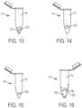
- Figs. 13-16illustrate exemplary embodiments of a sample stabilizer 200 being including within a container 14.
- anticoagulant lyophilized spheres 210are provided within collection cavity 70 of container 14. As blood 16 follows the attached flow of the present disclosure into the container 14, the anticoagulant lyophilized spheres 210 dissolve within the blood 16 upon contact with the blood 16.
- the sample stabilizer 200includes a floating anticoagulant coated open cell foam material 220.
- the sample stabilizer 200includes a floating anticoagulant coated floating ball 230.
- the container 14includes an anticoagulant coated wall surface 240 and a mixing ball 242.
Landscapes
- Health & Medical Sciences (AREA)
- Life Sciences & Earth Sciences (AREA)
- Engineering & Computer Science (AREA)
- Animal Behavior & Ethology (AREA)
- Public Health (AREA)
- Pathology (AREA)
- Physics & Mathematics (AREA)
- Biomedical Technology (AREA)
- Heart & Thoracic Surgery (AREA)
- Medical Informatics (AREA)
- Molecular Biology (AREA)
- Surgery (AREA)
- Hematology (AREA)
- General Health & Medical Sciences (AREA)
- Biophysics (AREA)
- Veterinary Medicine (AREA)
- Dermatology (AREA)
- Manufacturing & Machinery (AREA)
- Pain & Pain Management (AREA)
- Vascular Medicine (AREA)
- Measurement Of The Respiration, Hearing Ability, Form, And Blood Characteristics Of Living Organisms (AREA)
- Investigating Or Analysing Biological Materials (AREA)
- External Artificial Organs (AREA)
- Sampling And Sample Adjustment (AREA)
Description
- The present disclosure relates generally to devices adapted for use with biological fluids. More particularly, the present disclosure relates to devices for controlling the flow of blood.
US 3623475 discloses a tube for use in the automatic collection of a digital blood sample with its mouth fitted with a resilient detachable funnel member which can carry a capillary cannula and in which is held an absorbent annular plug through which pass and project two incisor lancets.US2015/351676 discloses a self-contained universal front-end automatic blood collection device.
The device collects a few micro-liters blood sample that is used for a broad range of blood analyzers. The design of the front-end closely mimics current phlebotomist practice and provides a number of unique features that ensure patient safety and sterility, improve collection efficacy, and prevent sample contamination and user cross contamination.EP1157660 discloses system for withdrawing body fluid from a body part in particular the finger pad, comprising a compression unit that can be deformed when the body part is pressed against it and increases the internal pressure in a region of the body part, and a withdrawal device. Deformation of the compression unit partially converts the primary pressing movement into a secondary movement which leads to an increase in the internal pressure in a region of the body part. The invention also comprises a system for stimulating the outflow of body fluid using a deformable compression unit.US2009/259145 discloses a container assembly including an outer container, a hollow inner member, and a closure. The outer container has a closed bottom, an open top, and a sidewall extending therebetween. The hollow inner member is disposed within the outer container and has an inner surface defining at least one capillary channel. The inner member includes a first end adjacent to the open top of the outer container and has an outer periphery seated against the sidewall of the outer container. The closure has a proximal end and a distal end. The closure proximal end is seated at least partially within the first end of the inner member to seal the outer container and inner member and define a fluid collection chamber. The closure distal end defines a recessed area shaped to direct fluid under capillary action to the at least one capillary channel in the inner member.- Blood sampling is a common health care procedure involving the withdrawal of at least a drop of blood from a patient. Blood samples are commonly taken from hospitalized, homecare, and emergency room patients either by finger stick, heel stick, or venipuncture. Once collected, blood samples may be analyzed to obtain medically useful information including chemical composition, hematology, or coagulation, for example. Blood tests determine the physiological and biochemical states of the patient, such as disease, mineral content, drug effectiveness, and organ function. Blood tests may be performed in a clinical laboratory or at the point-of-care near the patient.
- Lancet devices are used in the medical field for puncturing the skin of a patient to obtain a small sample of capillary blood from the patient. Certain diseases, such as diabetes, require that a patient's blood be tested on a regular basis to monitor, for example, the patient's blood sugar levels. Additionally, test kits, such as cholesterol test kits, often require a small blood sample for analysis. The blood collection procedure usually involves pricking a finger or other suitable body part in order to obtain the blood sample. Typically, the amount of blood needed for such tests is relatively small and a small puncture wound or incision normally provides a sufficient amount of blood for these tests.
- Upon puncturing the skin of a patient using a lancet device, the blood will spread and remain on a surface of the finger.
- The present disclosure provides a collection device which directs a flow of blood into a container and provides a controlled blood flow path that ensures blood flow from a collection site to a collection container.
- The device for attached flow of blood of the present disclosure achieves this using three key technical elements to control the flow of blood in the desired manner. First, controlling and guiding a blood sample from a skin surface of a patient to a collection housing via a first flow directing attachment portion. Second, controlling and guiding the blood sample from a first end of a collection housing to a second end of the collection housing via capillary transfer. Third, controlling and guiding the blood sample from the second end of the collection housing into a collection cavity of a collection container via a second flow directing attachment portion. With a first end of a housing in communication with a source of blood, a first flow directing attachment portion, a flow channel, a second flow directing attachment portion, and an interior wall surface of a container provide attachment portions to establish attached blood flow, for a first drop of blood and subsequent blood to follow, from the first end of the housing to a collection cavity of the container. A device for attached flow of blood according to the invention is defined by the features of claim 1. Preferred embodiments are defined within the dependent claims.
- In accordance with an embodiment of the present invention, a device for attached flow of blood includes a housing defining a centerline and having a first end, a second end, and a flow channel having an inlet and an outlet, a portion of the flow channel offset from the centerline of the housing, and the flow channel having a first flow directing attachment portion adjacent the inlet and a second flow directing attachment portion adjacent the outlet; and a container removably connectable to the housing, the container defining a collection cavity and having an interior wall, wherein, with the container connected to the housing, the outlet of the flow channel is in fluid communication with the collection cavity of the container and the outlet of the flow channel is adjacent the interior wall of the container.
- In one configuration, the first flow directing attachment portion provides a first fluid attachment point for blood to attach to for controlling the flow of blood from a skin surface to a portion of the housing. In another configuration, the second flow directing attachment portion provides a second fluid attachment point for blood to attach to for controlling the flow of blood from a portion of the housing to the collection cavity of the container. In yet another configuration, with the first end of the housing in communication with a source of blood, the first flow directing attachment portion, the flow channel, the second flow directing attachment portion, and the interior wall of the container provide attachment portions to establish attached blood flow, for a first drop of blood and subsequent blood to follow, from the first end of the housing to the collection cavity of the container. In one configuration, with the inlet of the flow channel in communication with a source of blood, the blood fluidly attaches to the first flow directing attachment portion and flows from the first flow directing attachment portion to the flow channel. In another configuration, the blood is subsequently pulled through the flow channel to the second flow directing attachment portion via capillary action. In yet another configuration, the blood fluidly attaches to the second flow directing attachment portion and the interior wall of the container to flow from the flow channel into the collection cavity of the container. In one configuration, the first end of the housing includes a sloped wall surface, the first flow directing attachment portion extends from the sloped wall surface, and the sloped wall surface defines a flow channel entry. In another configuration, the first flow directing attachment portion is an attachment pillar. In yet another configuration, the first flow directing attachment portion comprises a plurality of attachment pillars. In one configuration, the second flow directing attachment portion is an attachment lip. In another configuration, the second flow directing attachment portion is an extended capillary tube portion. In yet another configuration, the second flow directing attachment portion is an inward curved lip. In one configuration, the second flow directing attachment portion is a planar cut lip. In another configuration, the second flow directing attachment portion is an extended pillar structure. In yet another configuration, the outlet of the flow channel extends beyond the second end of the housing.
- In accordance with another embodiment of the present invention, a device for attached flow of blood includes a housing defining a centerline and having a first end, a second end, a hollow needle, and a flow channel having an inlet and an outlet, a portion of the flow channel offset from the centerline of the housing, the flow channel having a flow directing attachment portion adjacent the outlet, and the hollow needle between the first end of the housing and the flow channel; and a container removably connectable to the housing, the container defining a collection cavity and having an interior wall, wherein, with the container connected to the housing, the outlet of the flow channel is in fluid communication with the collection cavity of the container and the outlet of the flow channel is adjacent the interior wall of the container.
- In one configuration, the flow directing attachment portion provides a fluid attachment point for blood to attach to for controlling the flow of blood from a portion of the housing to the collection cavity of the container. In another configuration, with the first end of the housing in communication with a source of blood, the hollow needle, the flow channel, the flow directing attachment portion, and the interior wall of the container provide attachment portions to establish attached blood flow, for a first drop of blood and subsequent blood to follow, from the first end of the housing to the collection cavity of the container. In yet another configuration, with the inlet of the flow channel in communication with a source of blood, the blood fluidly attaches to a portion of the hollow needle and flows through the hollow needle to the flow channel. In one configuration, the blood is subsequently pulled through the flow channel to the flow directing attachment portion via capillary action. In another configuration, the blood fluidly attaches to the flow directing attachment portion and the interior wall of the container to flow from the flow channel into the collection cavity of the container. In yet another configuration, the housing includes a sloped wall surface between the hollow needle and the flow channel, and the sloped wall surface defines a flow channel entry. In one configuration, the flow directing attachment portion is an attachment lip. In another configuration, the flow directing attachment portion is an extended capillary tube portion. In yet another configuration, the flow directing attachment portion is an inward curved lip. In one configuration, the flow directing attachment portion is a planar cut lip. In another configuration, the flow directing attachment portion is an extended pillar structure. In yet another configuration, the outlet of the flow channel extends beyond the second end of the housing. In one configuration, the device further includes a flow directing ring around the hollow needle. In another configuration, the hollow needle includes a lancing blade. In yet another configuration, with the first end of the housing in communication with a source of blood, a first drop of blood attaches to the lancing blade and flows through the hollow needle to the flow channel.
- The above-mentioned and other features and advantages of this disclosure, and the manner of attaining them, will become more apparent and the disclosure itself will be better understood by reference to the following descriptions of embodiments of the disclosure taken in conjunction with the accompanying drawings. Embodiments according to the invention are shown in
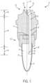
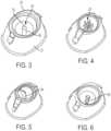
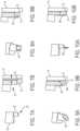
figures 17 to 24 . The other figures are showing similar embodiments. Fig. 1 is a cross-sectional view of a device for attached flow of blood.Fig. 2 is the device ofFig. 1 engaged with a finger.Fig. 3 is a perspective view of a first flow directing attachment portion of a device for attached flow of blood.Fig. 4 is a perspective view of a first flow directing attachment portion of a device for attached flow of blood.Fig. 5 is a perspective view of a first flow directing attachment portion of a device for attached flow of blood.Fig. 6 is a perspective view of a first flow directing attachment portion of a device for attached flow of blood.Fig. 7A is a perspective view of a second flow directing attachment portion of a device for attached flow of blood in accordance with an embodiment of the present invention.Fig. 7B is a perspective view of the attached flow of blood with a second flow directing attachment portion and an interior wall of a container.Fig. 8A is a perspective view of a second flow directing attachment portion of a device for attached flow of blood.Fig. 8B is a perspective view of the attached flow of blood with a second flow directing attachment portion and an interior wall of a container.Fig. 9A is a perspective view of a second flow directing attachment portion of a device for attached flow of blood.Fig. 9B is a perspective view of the attached flow of blood with a second flow directing attachment portion and an interior wall of a container.Fig. 10A is a perspective view of a second flow directing attachment portion of a device for attached flow of blood.Fig. 10B is a perspective view of the attached flow of blood with a second flow directing attachment portion and an interior wall of a container.Fig. 11 is a cross-sectional view of a device for attached flow of blood.Fig. 12 is an enlarged view of an open cell foam material taken alongsection 12 ofFig. 11 .Fig. 13 is a perspective view of a container having a sample stabilizer.Fig. 14 is a perspective view of a container having a sample stabilizer.Fig. 15 is a perspective view of a container having a sample stabilizer.Fig. 16 is a perspective view of a container having a sample stabilizer.Fig. 17 is a cross-sectional view of a device for attached flow of blood engaged with a finger in accordance with an embodiment of the present invention.Fig. 18 is a perspective view of a hollow needle of a device for attached flow of blood in accordance with another embodiment of the present invention.Fig. 19 is a perspective view of a hollow needle of a device for attached flow of blood in accordance with another embodiment of the present invention.Fig. 20 is a perspective view of a hollow needle of a device for attached flow of blood in accordance with another embodiment of the present invention.Fig. 21 is a perspective view of a hollow needle of a device for attached flow of blood in accordance with another embodiment of the present invention.Fig. 22 is a perspective view of a hollow needle of a device for attached flow of blood in accordance with another embodiment of the present invention.Fig. 23 is a perspective view of a hollow needle of a device for attached flow of blood in accordance with another embodiment of the present invention.Fig. 24 is a perspective view of a hollow needle of a device for attached flow of blood in accordance with another embodiment of the present invention.Fig. 25A is a perspective view of a container of a device for attached flow of blood, with the container connected to a housingFig. 25B is a perspective view of a container of a device for attached flow of blood, with the container removed from a housing in a first position.Fig. 25C is a perspective view of a container of a device for attached flow of blood, with the container removed from a housing in a second position, in accordance with an embodiment of the present invention.Fig. 26A is a perspective view of a container of a device for attached flow of blood, with the container connected to a housing,.Fig. 26B is a perspective view of a container of a device for attached flow of blood, with the container removed from a housing,.Fig. 27A is a perspective view of a container of a device for attached flow of blood, with the container connected to a housing,.Fig. 27B is a perspective view of a container of a device for attached flow of blood, with the container removed from a housing in a first position,.Fig. 27C is a perspective view of a container of a device for attached flow of blood, with the container removed from a housing in a second position.Fig. 28A is a perspective view of a container of a device for attached flow of blood, with the container connected to a housing.Fig. 28B is a perspective view of a container of a device for attached flow of blood, with the container removed from a housing.- Corresponding reference characters indicate corresponding parts throughout the several views. The exemplifications set out herein illustrate exemplary embodiments of the disclosure, and such exemplifications are not to be construed as limiting the scope of the disclosure in any manner.
- The following description is provided to enable those skilled in the art to make and use the described embodiments contemplated for carrying out the invention. Various modifications, variations, and alternatives, however, will remain readily apparent to those skilled in the art.
- For purposes of the description hereinafter, the terms "upper", "lower", "right", "left", "vertical", "horizontal", "top", "bottom", "lateral", "longitudinal", and derivatives thereof shall relate to the invention as it is oriented in the drawing figures. However, it is to be understood that the invention may assume alternative variations and step sequences, except where expressly specified to the contrary. It is also to be understood that the specific devices and processes illustrated in the attached drawings, and described in the following specification, are simply exemplary embodiments of the invention. Hence, specific dimensions and other physical characteristics related to the embodiments disclosed herein are not to be considered as limiting.
- The device for attached flow of
blood 10 of the present disclosure provides a controlled blood flow path that ensures attached blood flow from a collection site to a collection container. The device for attached flow ofblood 10 of the present disclosure achieves this using three key technical elements to control the flow of blood in the desired manner. First, controlling and guiding a blood sample from a skin surface of a patient to a collection housing via a first flow directing attachment portion. Second, controlling and guiding the blood sample from a first end of a collection housing to a second end of the collection housing via capillary transfer. Third, controlling and guiding the blood sample from the second end of the collection housing into a collection cavity of a collection container via a second flow directing attachment portion. Figs. 1-10B illustrate an exemplary embodiment of a device for attached flow of blood of the present disclosure. Referring toFigs. 1-10B , a device for attached flow ofblood 10 of the present disclosure provides a controlled blood flow path that ensures attached blood flow from a collection site to a collection container.- Upon puncturing the skin of a patient using a typical lancet device, the blood will spread and remain on a surface of the finger. Without controlling the blood and the flow of blood, the blood may remain on a surface of the finger and may not readily flow to a collection container.
- Referring to
Figs. 1-10B , in one exemplary embodiment, a device for attached flow, i.e., providing flow directing attachment portions for a blood sample to attach to for guiding and controlling the flow of the blood sample from a collection site to a collection container, ofblood 10 generally includes ahousing 12 and acollection container 14 that is removably connectable to thehousing 12. Thecontainer 14 defines acollection cavity 70 and includes an interior wall orinterior wall surface 72. - Referring to
Figs. 1-10B , thehousing 12 defines a centerline CL and includes afirst end 20, asecond end 22, and aflow channel 24. Theflow channel 24 includes aninlet 26 and anoutlet 28. A portion of theflow channel 24, e.g., amiddle portion 30, is offset from the centerline CL of thehousing 12. This ensures that theoutlet 28 of theflow channel 24 is adjacent to aninterior wall surface 72 of thecontainer 14, as described in more detail below. Theflow channel 24 also includes a first flow directingattachment portion 32 at theinlet 26 and a second flow directingattachment portion 34 at theoutlet 28. In one embodiment, theoutlet 28 of theflow channel 24 extends beyond thesecond end 22 of thehousing 12 as shown inFigs. 1 and2 . - Referring to
Figs. 1 and2 , with thecontainer 14 connected to thehousing 12, theoutlet 28 of theflow channel 24 is in fluid communication with thecollection cavity 70 of thecontainer 14 and theoutlet 28 of theflow channel 24 is adjacent theinterior wall surface 72 of thecontainer 14. - In one embodiment, the
first end 20 of thehousing 12 includes a slopedwall surface 36. In this manner, the slopedwall surface 36 provides physical structure, i.e., a wall surface, which allows the first flow directingattachment portion 32 to extend upwards from. For example, referring toFig. 1 , the first flow directingattachment portion 32 extends upwards from the slopedwall surface 36 to theinlet 26 of thehousing 12. In one embodiment, the sloped wall surface 38 defines a flow channel entry 38. - The device for attached flow of
blood 10 of the present disclosure provides a controlled blood flow path that ensures attached blood flow from a collection site to a collection container. The device for attached flow ofblood 10 of the present disclosure achieves this using three key technical elements to control the flow of blood in the desired manner. First, controlling and guiding a blood sample from a skin surface of a patient to a collection housing via a first flow directing attachment portion. Second, controlling and guiding the blood sample from a first end of a collection housing to a second end of the collection housing via capillary transfer. Third, controlling and guiding the blood sample from the second end of the collection housing into a collection cavity of a collection container via a second flow directing attachment portion. - For example, referring to
Fig. 2 , with thefirst end 20 of thehousing 12 in communication with a source ofblood 16, the first flow directingattachment portion 32, theflow channel 24, the second flow directingattachment portion 34, and theinterior wall surface 72 of thecontainer 14 provide attachment portions to establish attached blood flow, for a first drop ofblood 16 andsubsequent blood 16 to follow, from thefirst end 20 of thehousing 12 to acollection cavity 70 of thecontainer 14. - The first key blood
flow path element 40 involves directing the first drop ofblood 16 away from a surface S of a finger F in a direction towards acollection container 14. In one embodiment, with thefirst end 20 of thehousing 12 in communication with a source ofblood 16, the first flow directingattachment portion 32 provides a pillar which the first drop ofblood 16 attaches to and flows down and into theflow channel 24 of thehousing 12 in a controlled manner. In other words, a first drop ofblood 16 attaches to the first flow directingattachment portion 32 and flows from the first flow directingattachment portion 32 to theflow channel 24. - In one embodiment, the sloped
wall surface 36 provides a downward attached flow path from the first flow directingattachment portion 32 to theflow channel 24 of thehousing 12. After the first drop ofblood 16 attaches to and flows down the first flow directingattachment portion 32, thesubsequent blood 16 follows the attached blood flow path of the first drop ofblood 16 from thefirst end 20 of thehousing 12 to thecollection cavity 70 of thecontainer 14. - The second key blood
flow path element 42 involves directing theblood 16 down theflow channel 24 to the second flow directingattachment portion 34 in a direction towards acollection container 14. For example, the first drop ofblood 16, andsubsequent blood 16, is pulled through theflow channel 24 to the second flow directingattachment portion 34 via capillary motion. In one embodiment, theflow channel 24 is a capillary flow channel. In one embodiment, theflow channel 24 is a capillary tube that uses capillary forces to pull theblood 16 down theflow channel 24 away from the surface S of the finger F. - The third key blood flow path element 44 involves directing the
blood 16 from theflow channel 24 into thecollection container 14. Thedevice 10 of the present disclosure ensures transition from theflow channel 24 to thecontainer 14 via attached flow. For example, theblood 16 attaches to the second flow directingattachment portion 34 and theinterior wall surface 72 of thecontainer 14 to flow from theflow channel 24 into thecollection cavity 70 of thecontainer 14. - The third key blood flow path element 44 involving directing the
blood 16 from theflow channel 24 into thecollection container 14 is the reason that it is important that a portion of theflow channel 24, e.g., amiddle portion 30, is offset from the centerline CL of thehousing 12. This ensures that theoutlet 28 of theflow channel 24, and the second flow directingattachment portion 34, is adjacent to aninterior wall surface 72 of thecontainer 14 to ensure the transition of the attached blood flow from theflow channel 24 to thecontainer 14. - The
blood 16 will only flow down and out theflow channel 24 into thecontainer 14 if theblood 16 is able to find another portion to attach to. The second flow directingattachment portion 34 and theinterior wall surface 72 of thecontainer 14 provide such attachment portions to control theblood 16 to thecollection cavity 70 of thecontainer 14 via attached blood flow. - As described above, once this pathway of attached blood flow is established, the
subsequent blood 16 follows and flows along this attached blood flow. In the above-described manner, thedevice 10 of the present disclosure establishes attached blood flow, for a first drop ofblood 16 andsubsequent blood 16 to follow, from thefirst end 20 of thehousing 12 to acollection cavity 70 of thecontainer 14. - The first flow directing
attachment portion 32 may include a variety of different designs and structures as shown inFigs. 3-6 . Additional alternative designs and structures of the first flow directingattachment portion 32 are contemplated. For example, referring toFig. 3 , in one embodiment, the first flow directingattachment portion 32 is an attachment pillar 50. The attachment pillar 50 is a single pillar structure that may have a variable diameter and length. The pillar 50 may include hydrophilic surface properties to attract the first drop of blood and establish a flow path to the second capillary section. In one embodiment, the pillar 50 may have a diameter of between 0.25 mm to 4 mm, and a length of between 2 mm and 20 mm. - Referring to
Fig. 4 , in another embodiment, the first flow directingattachment portion 32 is a plurality ofattachment pillars 52. The plurality ofattachment pillars 52 may include pillars having different sizes and structures including a variety of different number of pillars. In one configuration, the plurality ofattachment pillars 52 provide multiple surfaces for the first drop of blood to establish a flow path without smearing to the side of the structure or pooling in an undesired location. Themultiple pillars 52 can also provide for additional capillary action due to the multiple capillary sections created between the individual pillar structures. In one configuration, the plurality ofattachment pillars 52 may include between 2 and 10 attachment pillars, such as between 5 and 10 attachment pillars. In one embodiment, the each pillar may have a diameter of between 0.25 mm to 4 mm, and a length of between 2 mm and 20 mm. - Referring to
Fig. 5 , in another embodiment, the first flow directingattachment portion 32 is a protrudingstructure 54. The protrudingstructure 54 guides the attached flow of blood and may include different shapes, sizes, and structures. In this configuration, the slanted structure provides a hydrophilic surface for the first drop of blood to attach to and be guided to the second capillary section. Optionally the thickness of the slanted structure may be from about 0.25 to about 5 mm. - Referring to
Fig. 6 , in another embodiment, the first flow directingattachment portion 32 is acapillary groove portion 56. Thecapillary groove portion 56 guides the attached flow of blood and may include different shapes, sizes, and number of grooves. In this configuration, the pillar structure having grooves aids with higher capillary force due to the increased surface in the grooves thereby acting as capillary channels for the first drop of blood to be wicked from the finger and transferred to the second capillary channel. In one configuration, the number of grooves provided may be between 1 and 20, and the diameter of each groove may be between 0.25 mm and 1 mm. - The second flow directing
attachment portion 34 may include a variety of different designs and structures as shown inFigs. 7A-10B . Additional alternative designs and structures of the second flow directingattachment portion 34 are contemplated. For example, referring toFigs. 1 and2 , in one embodiment, the second flow directingattachment portion 34 is anattachment lip 60. Theattachment lip 60 is a lip designed to establish attached blood flow into thecollection cavity 70 of thecontainer 14 as described above. Theattachment lip 60 provides a surface for the blood to expand and form a droplet to establish attachment to the collection cavity. - Referring to
Figs. 7A and 7B , in another embodiment, the second flow directingattachment portion 34 is an extendedcapillary tube portion 62. In one configuration, the extended capillary tube portion may extend between 2 mm and 10 mm beyond theflow channel 24. The extendedcapillary tube portion 62 may be spaces from the wall of the collection container a distance of less than 1 mm. - Referring to
Figs. 8A and 8B , in another embodiment, the second flow directingattachment portion 34 is an inwardcurved lip 64. The inward curved lip structure aids in the attachment of the blood from a portion of the housing to the surface of the collection cavity. In one configuration, the inward curved lip structure may extend beyond theflow channel 24 from about 0.5 to about 10 mm. - Referring to
Figs. 9A and 9B , in another embodiment, the second flow directingattachment portion 34 is aplanar cut lip 66. Theplanar cut lip 66 also aids in the formation of a blood droplet and the establishment of an attachment of blood to the surface of a collection cavity. In one configuration, the planar cut lip may have an angle from about 10° to about 80°. - Referring to
Figs. 10A and 10B , in another embodiment, the second flow directingattachment portion 34 is anextended pillar structure 68. In one configuration, the extended pillar structure may extend beyond the flow channel 24 a distance of from about 0.5 mm to about 10 mm. - Referring to
Figs. 1 ,2 ,17 , and25A-28B , exemplary embodiments of acollection container 14 of the present disclosure are shown. Additional alternative designs and structures of thecontainer 14 are contemplated. Acollection container 14 of the present disclosure is removably connectable to thehousing 12. Thecontainer 14 defines acollection cavity 70 and includes an interior wall orinterior wall surface 72. Referring toFigs. 1 and2 , with thecontainer 14 connected to thehousing 12, theoutlet 28 of theflow channel 24 is in fluid communication with thecollection cavity 70 of thecontainer 14 and theoutlet 28 of theflow channel 24 is adjacent theinterior wall surface 72 of thecontainer 14. In one configuration, the inner diameter of theflow channel 24 may be from about 0.5 mm to about 2 mm. - Referring to
Figs. 25A-25C , in one embodiment, thecontainer 14 includes a removablyconnectable cap 74 and atether element 76. In such an embodiment, thecap 74 is removed when thecontainer 14 is connected to thehousing 12 as shown inFig. 25A . Thetether element 76 ensures that thecap 74 still remains secured to a portion of thecontainer 14 with thecap 74 disconnected from an opentop end 78 of thecontainer 14 as shown inFig. 25B . Once a desired amount ofblood 16 is collected within thecontainer 14, thecontainer 14 is removed from thehousing 12 and thecap 74 is connected to thecontainer 14 to protectively seal theblood 16 within thecontainer 14 as shown inFig. 25C . - Referring to
Figs. 26A-26B , in one embodiment, thecontainer 14 includes aresealable septum 80. In such an embodiment, with thecontainer 14 connected to thehousing 12, a portion of theflow channel 24 pierces theseptum 80 so that theflow channel 24 is in fluid communication with thecollection cavity 70 of thecontainer 14. Once a desired amount ofblood 16 is collected within thecontainer 14, thecontainer 14 is removed from thehousing 12 and theseptum 80 automatically reseals to the closed, sealed position to protectively seal theblood 16 within thecontainer 14 as shown inFig. 26B . - Referring to
Figs. 27A-27C , in one embodiment, thecontainer 14 includes adeformable dispensing portion 82. In such an embodiment, with thecontainer 14 removed from thehousing 12, a portion of theblood 16 may be dispensed from thecontainer 14 by activation of thedeformable portion 82. For example, thedeformable portion 82 is transitionable between an initial position (Figs. 27A-27B ) in which theblood 16 is contained within thecollection cavity 70 and a deformed position (Fig. 27C ) in which a portion of theblood 16 is expelled from thecollection cavity 70 of thecontainer 14. Thedeformable portion 82 is squeezed to transition from the initial position (Figs. 27A-27B ) to the deformed position (Fig. 27C ). In this manner, theblood 16 may be transferred to a device intended to analyze the sample, e.g., such as a point-of-care testing device, a cartridge tester, or a near patient testing device, while minimizing the exposure of the medical practitioner to the blood sample. In one embodiment, thecontainer 14 also includes anend cap 84 to safely seal an exit portion 86 of thecontainer 14. When a user is ready to expel a portion ofblood 16 from thecontainer 14, theend cap 84 is removed from the exit portion 86 of thecontainer 14 before dispensingblood 16. - Referring to
Figs. 28A-28B , in one embodiment, thecontainer 14 includes anextension tube 88. Theextension tube 88 is compatible with analyzers and analyzing devices. Figs. 17-24 illustrate another exemplary embodiment of a device for attached flow of blood of the present disclosure. Referring toFigs. 17-24 , a device for attached flow ofblood 100 of the present disclosure provides a controlled blood flow path that ensures attached blood flow from a collection site to a collection container.- Upon puncturing the skin of a patient using a lancet device, the blood will spread and remain on a surface of the finger. Without controlling the blood and the flow of blood, the blood will remain on a surface of the finger and will not flow to a collection container.
- Referring to
Figs. 17-24 , in one exemplary embodiment, a device for attached flow ofblood 100 generally includes ahousing 112 and acollection container 14 that is removably connectable to thehousing 112. Thecontainer 14 defines acollection cavity 70 and includes an interior wall orinterior wall surface 72. Thesame containers 14 that are compatible with thedevice 10 described above with reference toFigs. 1-10B are compatible with thedevice 100 described with reference toFigs. 17-24 . - Referring to
Fig. 17 , thehousing 112 defines a centerline CL and includes afirst end 120, asecond end 122, ahollow needle 123, and aflow channel 124. Theflow channel 24 includes aninlet 126 and anoutlet 128. A portion of theflow channel 124, e.g., abottom portion 130, is offset from the centerline CL of thehousing 112. This ensures that theoutlet 128 of theflow channel 124 is adjacent to aninterior wall surface 72 of thecontainer 14, as described in more detail below. Theflow channel 124 also includes a flow directingattachment portion 134 at theoutlet 128. In one embodiment, theoutlet 128 of theflow channel 124 extends beyond thesecond end 122 of thehousing 112 as shown inFig. 17 . In one embodiment, thehollow needle 123 is between thefirst end 120 of thehousing 112 and theflow channel 124. - In the embodiment shown in
Figs. 17-24 , thehollow needle 123 functions similar to the first flow directingattachment portion 32 described above with respect todevice 10 shown inFigs. 1-10B . - Referring to
Fig. 17 , with thecontainer 14 connected to thehousing 112, theoutlet 128 of theflow channel 124 is in fluid communication with thecollection cavity 70 of thecontainer 14 and theoutlet 128 of theflow channel 124 is adjacent theinterior wall surface 72 of thecontainer 14. - Upon puncturing the skin of a patient using a lancet device, the blood will spread and remain on a surface of the finger. Without controlling the blood and the flow of blood, the blood will remain on a surface of the finger and will not flow to a collection container.
- The device for attached flow of
blood 100 of the present disclosure provides a controlled blood flow path that ensures attached blood flow from a collection site to a collection container. The device for attached flow ofblood 100 of the present disclosure achieves this using three key technical elements to control the flow of blood in the desired manner. - For example, referring to
Fig. 17 , with thefirst end 120 of thehousing 112 in communication with a source ofblood 16, thehollow needle 123, theflow channel 124, the flow directingattachment portion 134, and theinterior wall surface 72 of thecontainer 14 provide attachment portions to establish attached blood flow, for a first drop ofblood 16 andsubsequent blood 16 to follow, from thefirst end 120 of thehousing 112 to thecollection cavity 70 of thecontainer 14. - The first key blood
flow path element 140 involves directing the first drop ofblood 16 away from the surface S of the finger F in a direction towards acollection container 14. In one embodiment, with thefirst end 120 of thehousing 112 in communication with a source ofblood 16, a first drop ofblood 16 attaches to a portion of thehollow needle 123 and flows through thehollow needle 123 to theflow channel 124 in a controlled manner as shown inFig. 17 . - In this manner, a portion of the
hollow needle 123 provides an attachment portion that functions similar to the first flow directingattachment portion 32 described above with respect todevice 10 shown inFigs. 1-10B . Thedevice 100 of the present disclosure including ahollow needle 123 provides an advantage in that thehollow needle 123 can also be used to lance a skin surface S of a finger F to provide a source ofblood 16. In such an embodiment, no separate lancet device is required. For example, in one embodiment, thehollow needle 123 may include a lancingblade 151 that can be used to lance a skin surface S of a finger F to provide a source ofblood 16. In such an embodiment, with thefirst end 120 of thehousing 112 in communication with a source ofblood 16, a first drop ofblood 16, andsubsequent blood 16, attaches to the lancingblade 151 and flows through thehollow needle 123 to theflow channel 124. - After the first drop of
blood 16 attaches to a portion of thehollow needle 123 and flows through thehollow needle 123, thesubsequent blood 16 follows the attached blood flow path of the first drop ofblood 16 from thefirst end 120 of thehousing 112 to thecollection cavity 70 of thecontainer 14. - The second key blood
flow path element 142 involves directing theblood 16 or pulling theblood 16 through theflow channel 124 to the flow directingattachment portion 134 via capillary motion. In one embodiment, the second key bloodflow path element 142 involves directing theblood 16 or pulling theblood 16 through thehollow needle 123 and theflow channel 124 to the flow directingattachment portion 134 via capillary motion in a direction towards acollection container 14. For example, the first drop ofblood 16, andsubsequent blood 16, is pulled through theflow channel 124 to the flow directingattachment portion 134 via capillary motion. In one embodiment, theflow channel 124 is a capillary flow channel. In one embodiment, theflow channel 124 is a capillary tube that uses capillary forces to pull theblood 16 down theflow channel 124 away from the surface S of the finger F. - In one embodiment, the
housing 112 includes a slopedwall surface 136 between thehollow needle 123 and theflow channel 124. In one embodiment, the slopedwall surface 138 defines aflow channel entry 138. In one embodiment, the slopedwall surface 136 provides a downward attached flow path from thehollow needle 123 to theflow channel 124 of thehousing 112. - The third key blood
flow path element 144 involves directing theblood 16 from theflow channel 124 into thecollection container 14. Thedevice 100 of the present disclosure ensures transition from theflow channel 124 to thecontainer 14 via attached flow. For example, theblood 16 attaches to the flow directingattachment portion 134 and theinterior wall surface 72 of thecontainer 14 to flow from theflow channel 124 into thecollection cavity 70 of thecontainer 14. - The third key blood
flow path element 144 involving directing theblood 16 from theflow channel 124 into thecollection container 14 is the reason that it is important that a portion of theflow channel 124, e.g., abottom portion 130, is offset from the centerline CL of thehousing 112. This ensures that theoutlet 128 of theflow channel 124, and the flow directingattachment portion 134, is adjacent to aninterior wall surface 72 of thecontainer 14 to ensure the transition of the attached blood flow from theflow channel 124 to thecontainer 14. - The
blood 16 will only flow down and out theflow channel 124 into thecontainer 14 if theblood 16 is able to find another portion to attach to. The flow directingattachment portion 134 and theinterior wall surface 72 of thecontainer 14 provide such attachment portions to control theblood 16 to thecollection cavity 70 of thecontainer 14 via attached blood flow. - As described above, once this pathway of attached blood flow is established, the
subsequent blood 16 follows and flows along this attached blood flow. In the above-described manner, thedevice 100 of the present disclosure establishes attached blood flow, for a first drop ofblood 16 andsubsequent blood 16 to follow, from thefirst end 120 of thehousing 112 to acollection cavity 70 of thecontainer 14. - As discussed above, a portion of the
hollow needle 123 that provides an attachment portion for the flow ofblood 16 functions similar to the first flow directingattachment portion 32 described above with respect todevice 10 shown inFigs. 1-10B . - The
hollow needle 123 may include a variety of different designs and structures as shown inFigs. 18-24 . Additional alternative designs and structures of thehollow needle 123 are contemplated. For example, referring toFigs. 18 and 19 , in one embodiment, thehollow needle 123 includes a bevel cut hollow needle. In one configuration, the bevel of the needle may have a length of between 3 mm and 6 mm and the lumen inner diameter may be between 0.25 mm and 4 mm. - As discussed above, referring to
Figs. 20 and 21 , in one embodiment, thehollow needle 123 may include a lancingblade 151 that can be used to lance a skin surface S of a finger F to provide a source ofblood 16. - Referring to
Fig. 21 , in another embodiment, thehollow needle 123 includes aflow directing ring 155 around thehollow needle 123. Theflow directing ring 155 preventsblood 16 from flowing down thehollow needle 123 and ensures that theblood 16 flows through thehollow needle 123 to theflow channel 124.Figs. 22-24 illustrate additional alternative designs and structures of thehollow needle 123. The needle bevels serve as the additional first flow directed attachment sections, similar to thepillar structure portion 32 as described above with reference toFig. 3 . - The flow directing
attachment portion 134 may include a variety of different designs and structures as shown inFigs. 7A-10B . Additional alternative designs and structures of the flow directingattachment portion 134 are contemplated. The flow directingattachment portion 134 ofdevice 100 may include the same designs and structures as the second flow directingattachment portion 34 ofdevice 10 as described above and as shown inFigs. 7A-10B . - Another advantage of a
device device sample stabilizer 200 within ablood sample 16. Referring toFigs. 11 and12 , in one embodiment, asample stabilizer 200 is positioned within a portion offlow channel blood sample 16, as theblood sample 16 follows the controlled attached blood flow from a collection site to a collection container of the present disclosure, will pass through thesample stabilizer 200. In this manner, theblood sample 16 may be mixed with asample stabilizer 200, such as an anticoagulant or other additive, provided within a portion ofdevice sample stabilizer 200 can be an anticoagulant, or a substance designed to preserve a specific element within the blood such as, for example, RNA, protein analyte, or other element. - Referring to
Figs. 11 and12 , in one embodiment, thesample stabilizer 200 includes a material 202 includingpores 204 and a dry anticoagulant powder 206 that is within thepores 204 of thematerial 202. In this manner, thedevice flow channel material 202 is an open cell foam that contains dry anticoagulant dispersed within the cells of the open cell foam to promote the effectiveness of the flow-through mixing and anticoagulant uptake. In one embodiment, thesample stabilizer 200 is the dry anticoagulant powder 206. - In one embodiment, the open cell foam may be treated with an anticoagulant to form a dry anticoagulant powder 206 finely distributed throughout the
pores 204 of the open cell foam. As theblood sample 16 flows through theflow channel blood sample 16 passes through the open cell foam and is exposed to the anticoagulant powder 206 available throughout the internal pore structure of the open cell foam. In this manner, theblood sample 16 dissolves and mixes with the dry anticoagulant powder 206 while passing through the material 202 or open cell foam. - The open cell foam may be a soft deformable open cell foam that is inert to blood, for example, a melamine foam, such as Basotect® foam commercially available from BASF, or may consist of a formaldehyde-melamine-sodium bisulfite copolymer. The open cell foam may also be a flexible, hydrophilic open cell foam that is substantially resistant to heat and organic solvents. In one embodiment, the foam may include a sponge material.
- The anticoagulant or other additive may be introduced into the open cell foam by soaking the foam in a liquid solution of the additive and water and subsequently evaporating the water forming a dry additive powder finely distributed throughout the internal structure of the foam.
Figs. 13-16 illustrate exemplary embodiments of asample stabilizer 200 being including within acontainer 14.- For example, referring to
Fig. 13 , in one embodiment, anticoagulantlyophilized spheres 210 are provided withincollection cavity 70 ofcontainer 14. Asblood 16 follows the attached flow of the present disclosure into thecontainer 14, the anticoagulantlyophilized spheres 210 dissolve within theblood 16 upon contact with theblood 16. - Referring to
Fig. 14 , in another embodiment, thesample stabilizer 200 includes a floating anticoagulant coated opencell foam material 220. Referring toFig. 15 , in another embodiment, thesample stabilizer 200 includes a floating anticoagulant coated floatingball 230. Referring toFig. 16 , in another embodiment, thecontainer 14 includes an anticoagulantcoated wall surface 240 and amixing ball 242. - While this disclosure has been described as having exemplary designs, the present disclosure can be further modified within the scope of this disclosure. This application is therefore intended to cover any variations, uses, or adaptations of the disclosure using its general principles. Further, this application is intended to cover such departures from the present disclosure as come within known or customary practice in the art to which this disclosure pertains and which fall within the limits of the appended claims.
Claims (15)
- A device (100) for attached flow of blood, the device comprising:a housing (112) defining a centerline (CL) and having a first end (120), a second end (122), and a flow channel (124) having an inlet (126) and an outlet (128), a portion of the flow channel (124) offset from the centerline (CL) of the housing (112), and the flow channel (124) having a first flow directing attachment portion (32) adjacent the inlet (126) and a second flow directing attachment portion (134) adjacent the outlet;a finger support member (300) connected to the housing (112); anda container (14) removably connectable to the housing (112), the container (14) defining a collection cavity (70) and having an interior wall (72),wherein the finger support member (300) is configured to be actuated to force a blood sample from a patient's finger into the inlet (126) of the housing (112), andwherein, with the container (14) connected to the housing (112), the outlet (128) of the flow channel (124) is in fluid communication with the collection cavity (70) of the container (14) and the outlet (128) of the flow channel (124) and the second flow directing attachment portion (134) are adjacent the interior wall (72) of the container (14).
- The device of claim 1, wherein said second flow directing attachment portion (134) offset from the centerline (CL) of the housing (112).
- The device of claim 1, wherein the first flow directing attachment portion (32) provides a first fluid attachment point for blood to attach to for controlling the flow of blood from a skin surface to a portion of the housing (112).
- The device of claim 1, wherein the second flow directing attachment portion (134) provides a second fluid attachment point for blood to attach to for controlling the flow of blood from a portion of the housing (112) to the collection cavity (70) of the container (14).
- The device of claim 1, wherein, with the first end (120) of the housing (112) in communication with the patient's finger, the first flow directing attachment portion (32), the flow channel (124), the second flow directing attachment portion (134), and the interior wall (72) of the container (14) provide attachment portions to establish attached blood flow, for a first drop of blood and subsequent blood to follow, from the first end (120) of the housing (112) to the collection cavity (70) of the container (14).
- The device of claim 1, wherein, with the inlet (126) of the flow channel (124) in communication with the patient's finger, the blood fluidly attaches to the first flow directing attachment portion (32) and flows from the first flow directing attachment portion (32) to the flow channel (124).
- The device of claim 6, wherein the blood is subsequently pulled through the flow channel (124) to the second flow directing attachment portion (134) via capillary action.
- The device of claim 7, wherein, the blood fluidly attaches to the second flow directing attachment portion (134) and the interior wall (72) of the container (14) to flow from the flow channel (124) into the collection cavity (70) of the container (14).
- The device of claim 1, wherein the first end (120) of the housing (112) includes a sloped wall surface (136), the first flow directing attachment portion (32) extends from the sloped wall surface (136), and the sloped wall surface (136) defines a flow channel entry (138).
- The device of claim 1, wherein the first flow directing attachment portion (32) is an attachment pillar (50,52).
- The device of claim 1, wherein the second flow directing attachment portion (134) is an attachment lip (60).
- The device of claim 1, wherein the second flow directing attachment portion (134) is an extended capillary tube portion (62).
- The device of claim 1, wherein the second flow directing attachment portion (134) is an inward curved lip (64).
- The device of claim 1, wherein the second flow directing attachment portion (134) is a planar cut lip (66).
- The device of claim 1, wherein the second flow directing attachment portion (134) is an extended pillar structure (68).
Priority Applications (1)
| Application Number | Priority Date | Filing Date | Title |
|---|---|---|---|
| EP24164531.6AEP4364661A3 (en) | 2016-08-24 | 2017-08-23 | A device for the attached flow of blood |
Applications Claiming Priority (4)
| Application Number | Priority Date | Filing Date | Title |
|---|---|---|---|
| US201662378971P | 2016-08-24 | 2016-08-24 | |
| EP20214283.2AEP3811865B1 (en) | 2016-08-24 | 2017-08-23 | A device for the attached flow of blood |
| PCT/US2017/048147WO2018039307A1 (en) | 2016-08-24 | 2017-08-23 | A device for the attached flow of blood |
| EP17762279.2AEP3503807B1 (en) | 2016-08-24 | 2017-08-23 | A device for the attached flow of blood |
Related Parent Applications (2)
| Application Number | Title | Priority Date | Filing Date |
|---|---|---|---|
| EP20214283.2ADivisionEP3811865B1 (en) | 2016-08-24 | 2017-08-23 | A device for the attached flow of blood |
| EP17762279.2ADivisionEP3503807B1 (en) | 2016-08-24 | 2017-08-23 | A device for the attached flow of blood |
Related Child Applications (1)
| Application Number | Title | Priority Date | Filing Date |
|---|---|---|---|
| EP24164531.6ADivisionEP4364661A3 (en) | 2016-08-24 | 2017-08-23 | A device for the attached flow of blood |
Publications (3)
| Publication Number | Publication Date |
|---|---|
| EP4059427A1 EP4059427A1 (en) | 2022-09-21 |
| EP4059427C0 EP4059427C0 (en) | 2024-03-20 |
| EP4059427B1true EP4059427B1 (en) | 2024-03-20 |
Family
ID=59746370
Family Applications (7)
| Application Number | Title | Priority Date | Filing Date |
|---|---|---|---|
| EP17761172.0AActiveEP3503806B1 (en) | 2016-08-24 | 2017-08-23 | A device for obtaining a blood sample |
| EP20192101.2AActiveEP3760122B1 (en) | 2016-08-24 | 2017-08-23 | A device for obtaining a blood sample |
| EP23167764.2APendingEP4233722A3 (en) | 2016-08-24 | 2017-08-23 | A device for obtaining a blood sample |
| EP24164531.6APendingEP4364661A3 (en) | 2016-08-24 | 2017-08-23 | A device for the attached flow of blood |
| EP20214283.2AActiveEP3811865B1 (en) | 2016-08-24 | 2017-08-23 | A device for the attached flow of blood |
| EP22172551.8AActiveEP4059427B1 (en) | 2016-08-24 | 2017-08-23 | A device for the attached flow of blood |
| EP17762279.2AActiveEP3503807B1 (en) | 2016-08-24 | 2017-08-23 | A device for the attached flow of blood |
Family Applications Before (5)
| Application Number | Title | Priority Date | Filing Date |
|---|---|---|---|
| EP17761172.0AActiveEP3503806B1 (en) | 2016-08-24 | 2017-08-23 | A device for obtaining a blood sample |
| EP20192101.2AActiveEP3760122B1 (en) | 2016-08-24 | 2017-08-23 | A device for obtaining a blood sample |
| EP23167764.2APendingEP4233722A3 (en) | 2016-08-24 | 2017-08-23 | A device for obtaining a blood sample |
| EP24164531.6APendingEP4364661A3 (en) | 2016-08-24 | 2017-08-23 | A device for the attached flow of blood |
| EP20214283.2AActiveEP3811865B1 (en) | 2016-08-24 | 2017-08-23 | A device for the attached flow of blood |
Family Applications After (1)
| Application Number | Title | Priority Date | Filing Date |
|---|---|---|---|
| EP17762279.2AActiveEP3503807B1 (en) | 2016-08-24 | 2017-08-23 | A device for the attached flow of blood |
Country Status (13)
| Country | Link |
|---|---|
| US (5) | US11771352B2 (en) |
| EP (7) | EP3503806B1 (en) |
| JP (8) | JP7104026B2 (en) |
| KR (4) | KR102460682B1 (en) |
| CN (4) | CN115192014B (en) |
| AU (4) | AU2017315323B2 (en) |
| BR (2) | BR112019003638A2 (en) |
| CA (2) | CA3034842A1 (en) |
| ES (4) | ES2834078T3 (en) |
| MX (4) | MX2019002218A (en) |
| PL (1) | PL3503807T3 (en) |
| RU (4) | RU2747438C2 (en) |
| WO (2) | WO2018039305A1 (en) |
Families Citing this family (34)
| Publication number | Priority date | Publication date | Assignee | Title |
|---|---|---|---|---|
| US20100256524A1 (en) | 2009-03-02 | 2010-10-07 | Seventh Sense Biosystems, Inc. | Techniques and devices associated with blood sampling |
| US20130158482A1 (en) | 2010-07-26 | 2013-06-20 | Seventh Sense Biosystems, Inc. | Rapid delivery and/or receiving of fluids |
| WO2012021801A2 (en) | 2010-08-13 | 2012-02-16 | Seventh Sense Biosystems, Inc. | Systems and techniques for monitoring subjects |
| WO2012064802A1 (en) | 2010-11-09 | 2012-05-18 | Seventh Sense Biosystems, Inc. | Systems and interfaces for blood sampling |
| CN103874461B (en) | 2011-04-29 | 2017-05-10 | 第七感生物系统有限公司 | Devices for collecting and/or manipulating blood spots or other bodily fluids |
| WO2019067567A1 (en)* | 2017-09-26 | 2019-04-04 | Juno Diagnostics, Inc. | Devices, systems and methods for biomarker analysis |
| US20190099117A1 (en)* | 2017-10-02 | 2019-04-04 | Reliant Immune Diagnostics, Inc | Finger cuff having vibration mechanism for use in performing a finger prick |
| CA3080117A1 (en) | 2017-10-27 | 2019-05-02 | Juno Diagnostics, Inc. | Devices, systems and methods for ultra-low volume liquid biopsy |
| JP6905953B2 (en)* | 2018-05-15 | 2021-07-21 | 富士フイルム株式会社 | Blood sample guide device and blood test kit |
| EP3801259B1 (en)* | 2018-05-25 | 2023-07-19 | Becton, Dickinson and Company | Blood collection assembly with vibration module |
| BR112021004090A2 (en)* | 2018-09-06 | 2021-05-25 | Becton, Dickinson And Company | arterial blood gas collection system |
| BR112021015617A2 (en)* | 2019-02-14 | 2021-10-05 | Becton, Dickinson And Company | CAPILLARY COLLECTOR WITH ROTATING CONNECTION |
| BE1027338B1 (en)* | 2019-06-04 | 2021-01-14 | Inst Of Tropical Medicine | FINGER PRICKER COLLECTOR |
| JP7157711B2 (en)* | 2019-07-19 | 2022-10-20 | 株式会社日立ハイテク | Blood collection device |
| WO2021061751A1 (en) | 2019-09-23 | 2021-04-01 | Gateway Genomics, Llc | Methods, compositions, and kits for determining the sex of a fetus |
| WO2021091380A1 (en)* | 2019-11-07 | 2021-05-14 | Stichting Het Nederlands Kanker Instituut-Antoni van Leeuwenhoek Ziekenhuis | Blood collection device and method for the self-collection of blood by a user |
| JP2023527642A (en)* | 2020-03-31 | 2023-06-30 | プレシヘルス エスアー | Bodily fluid collection device and method of use |
| GB202004718D0 (en)* | 2020-03-31 | 2020-05-13 | Osler Diagnostics Ltd | Capillary blood sampling |
| WO2022043748A2 (en)* | 2020-08-23 | 2022-03-03 | Preci Health Sa | Capillary blood sampling device and method of use |
| GB2598334B (en) | 2020-08-26 | 2022-11-30 | Mowgli Innovations Ltd | Finger receptacle and holding device |
| CN117580506A (en)* | 2021-06-29 | 2024-02-20 | 贝克顿·迪金森公司 | capillary blood collection device |
| WO2023278234A1 (en)* | 2021-06-29 | 2023-01-05 | Becton, Dickinson And Company | Capillary blood collection device |
| CN117597069A (en) | 2021-06-29 | 2024-02-23 | 贝克顿·迪金森公司 | Simulation device for capillary blood collection |
| WO2023278225A1 (en)* | 2021-06-29 | 2023-01-05 | Becton, Dickinson And Company | Capillary blood collection device |
| CN117597195A (en)* | 2021-06-29 | 2024-02-23 | 贝克顿·迪金森公司 | Sample container for capillary blood collection |
| KR20240024243A (en)* | 2021-06-29 | 2024-02-23 | 백톤 디킨슨 앤드 컴퍼니 | Capillary Blood Collection Device |
| US20240315619A1 (en)* | 2021-06-29 | 2024-09-26 | Becton, Dickinson And Company | Blood Collection Kit With Blood Collection Devices of Multiple Sizes and Associated Sizing Systems and Methods |
| EP4362791A4 (en)* | 2021-06-29 | 2025-04-30 | Becton, Dickinson and Company | Capillary blood collection device |
| KR20240024244A (en)* | 2021-06-29 | 2024-02-23 | 백톤 디킨슨 앤드 컴퍼니 | Capillary Blood Collection Device |
| JP2024538133A (en)* | 2021-10-15 | 2024-10-18 | ベクトン・ディキンソン・アンド・カンパニー | Additive mix for blood sample collection |
| US11957465B2 (en) | 2022-08-23 | 2024-04-16 | Reddrop Dx, Inc. | Accelerated ergonomic collection of capillary blood |
| BE1030990B1 (en)* | 2022-10-25 | 2024-05-28 | Inst Voor Tropische Geneeskunde | BLOOD SAMPLING DEVICE FOR COLLECTION OF A BLOOD SAMPLE FROM A FINGER OR TOE |
| EP4491118A1 (en) | 2023-07-13 | 2025-01-15 | Becton, Dickinson and Company | Collector accessory for small volume collection containers and related sample collection methods |
| WO2025064983A1 (en)* | 2023-09-21 | 2025-03-27 | Becton, Dickinson And Company | Lancing finger sleeve |
Family Cites Families (160)
| Publication number | Priority date | Publication date | Assignee | Title |
|---|---|---|---|---|
| US2646799A (en) | 1951-02-14 | 1953-07-28 | Jr George W Jacoby | Blood lancet |
| CH500707A (en)* | 1968-07-26 | 1970-12-31 | Micromedic Systems Inc | Device for performing percutaneous and digital blood sampling |
| CH522395A (en)* | 1968-07-26 | 1972-05-15 | Micromedic Systems Inc | Test tube intended for percutaneous and digital blood sampling |
| US3630191A (en) | 1969-02-27 | 1971-12-28 | Gilford Instr Labor Inc | Apparatus and method for filling capillary tubing with fluids |
| CH538277A (en) | 1970-09-04 | 1973-06-30 | Micromedic Systems Inc | Percutaneous blood test device |
| US4024857A (en) | 1974-12-23 | 1977-05-24 | Becton, Dickinson And Company | Micro blood collection device |
| JPS51122982A (en)* | 1974-12-23 | 1976-10-27 | Becton Dickinson Co | Small blood sampling unit |
| US4411163A (en) | 1981-07-27 | 1983-10-25 | American Hospital Supply Corporation | Ventable sample collection device |
| US4397318A (en) | 1981-08-10 | 1983-08-09 | Becton Dickinson And Company | Blood collector for microcollection container |
| US4620549A (en) | 1985-01-25 | 1986-11-04 | Becton, Dickinson And Company | Blood collection assembly |
| US4646753A (en) | 1985-06-11 | 1987-03-03 | Becton, Dickinson And Company | Blood collector for microcollection container |
| DE3541041A1 (en)* | 1985-11-19 | 1987-05-21 | Sarstedt Kunststoff | BLOOD COLLECTOR |
| US4690153A (en)* | 1985-11-29 | 1987-09-01 | Becton, Dickinson And Company | Flow inducing means for small volume containers |
| US4791938A (en) | 1987-11-16 | 1988-12-20 | Nanci Van Valkenburg | Capillary blood collector and method |
| US5014718A (en) | 1988-01-22 | 1991-05-14 | Safety Diagnostics, Inc. | Blood collection and testing method |
| US5070886A (en) | 1988-01-22 | 1991-12-10 | Safety Diagnostice, Inc. | Blood collection and testing means |
| DE4000968C1 (en)* | 1990-01-16 | 1991-06-20 | Dieter 2090 Drage De Wendelborn | Blood sampling apparatus - has blood observation chamber mounted in sampling vessel stopper |
| US5309924A (en)* | 1992-04-29 | 1994-05-10 | Peabody Alan M | Spill-proof blood collection device |
| US5384096A (en) | 1993-05-12 | 1995-01-24 | Becton, Dickinson And Company | Microcollection tube assembly |
| HU219921B (en) | 1993-10-20 | 2001-09-28 | Ervin Lipscher | Device for making blood test, especially from fingers |
| US5485856A (en) | 1994-04-22 | 1996-01-23 | Buckland; Peter E. | Hand immobilizing and positioning apparatus for x-ray examinations |
| JPH08317918A (en) | 1995-05-25 | 1996-12-03 | Advance Co Ltd | Blood drawing device |
| US5569223A (en) | 1995-06-06 | 1996-10-29 | Home Access Health Corporation | Apparatus and method for enhancing blood flow to obtain a blood sample |
| DE29514084U1 (en) | 1995-09-01 | 1995-11-02 | Biosafe Diagnostics Corp., Lincolnshire, Ill. | Blood collection and test device |
| US5662127A (en) | 1996-01-17 | 1997-09-02 | Bio-Plas, Inc. | Self-contained blood withdrawal apparatus and method |
| US5714125A (en) | 1996-03-07 | 1998-02-03 | Medical Safety Products, Inc. | Device for collecting a blood sample from a plastic segment tube |
| US20020010406A1 (en) | 1996-05-17 | 2002-01-24 | Douglas Joel S. | Methods and apparatus for expressing body fluid from an incision |
| US5951493A (en) | 1997-05-16 | 1999-09-14 | Mercury Diagnostics, Inc. | Methods and apparatus for expressing body fluid from an incision |
| US5951492A (en) | 1996-05-17 | 1999-09-14 | Mercury Diagnostics, Inc. | Methods and apparatus for sampling and analyzing body fluid |
| EP1579814A3 (en) | 1996-05-17 | 2006-06-14 | Roche Diagnostics Operations, Inc. | Methods and apparatus for sampling and analyzing body fluid |
| EP1862116A3 (en) | 1996-05-17 | 2009-02-25 | Roche Diagnostics Operations, Inc. | Disposable element for use in a body fluid sampling device |
| US5857983A (en) | 1996-05-17 | 1999-01-12 | Mercury Diagnostics, Inc. | Methods and apparatus for sampling body fluid |
| US6706000B2 (en) | 1997-11-21 | 2004-03-16 | Amira Medical | Methods and apparatus for expressing body fluid from an incision |
| US6086545A (en) | 1998-04-28 | 2000-07-11 | Amira Medical | Methods and apparatus for suctioning and pumping body fluid from an incision |
| JP4210782B2 (en) | 1999-10-13 | 2009-01-21 | アークレイ株式会社 | Blood sampling position indicator |
| DE10026172A1 (en) | 2000-05-26 | 2001-11-29 | Roche Diagnostics Gmbh | Body fluid withdrawal system |
| DE10026170A1 (en)* | 2000-05-26 | 2001-12-06 | Roche Diagnostics Gmbh | Body fluid withdrawal system |
| RU2269954C2 (en) | 2000-06-09 | 2006-02-20 | Дайэбитиз Дайэгностикс, Инк. | Cap for lancet device for punching dermal tissue (versions), cap for lancet device for punching tip of finger, cap for lancet device for punching curvilinear dermal tissue and lancet device for punching dermal tissue |
| US6551267B1 (en) | 2000-10-18 | 2003-04-22 | Becton, Dickinson And Company | Medical article having blood-contacting surface |
| KR100788305B1 (en) | 2001-01-12 | 2007-12-27 | 아크레이 인코퍼레이티드 | Puncture device, its manufacture method, pump mechanism and suction device |
| JP2002219115A (en) | 2001-01-26 | 2002-08-06 | Matsushita Electric Works Ltd | Blood collecting device |
| US20040092843A1 (en) | 2001-02-22 | 2004-05-13 | Doron Kreiser | Device and method for measuring fetal blood pH |
| US20020188223A1 (en) | 2001-06-08 | 2002-12-12 | Edward Perez | Devices and methods for the expression of bodily fluids from an incision |
| US7749174B2 (en) | 2001-06-12 | 2010-07-06 | Pelikan Technologies, Inc. | Method and apparatus for lancet launching device intergrated onto a blood-sampling cartridge |
| JP2003070771A (en) | 2001-09-07 | 2003-03-11 | Omron Corp | Equipment and system for organism information measurement and method of organism information measurement management |
| CA2461370A1 (en) | 2001-09-26 | 2003-05-15 | F. Hoffmann-La Roche Ag | Method and apparatus for sampling bodily fluid |
| US20030212344A1 (en)* | 2002-05-09 | 2003-11-13 | Vadim Yuzhakov | Physiological sample collection devices and methods of using the same |
| USD488588S1 (en) | 2002-12-13 | 2004-04-13 | James P. Murphy | Finger accessory appliance |
| US20040127818A1 (en) | 2002-12-27 | 2004-07-01 | Roe Steven N. | Precision depth control lancing tip |
| GB0301587D0 (en)* | 2003-01-23 | 2003-02-26 | Epsom & St Helier Nhs Trust | A lancet holding device |
| WO2004078041A2 (en) | 2003-02-13 | 2004-09-16 | Toru Nakayama | Painless blood-collecting method |
| DE10315396A1 (en)* | 2003-04-04 | 2004-10-14 | Lieblein, Martin, Dr. | Automatic blood sugar monitor and warning system, for hypo- and hyperglycemia, has a finger stall containing the electromagnetic pricker and test strips with a glucose enzyme linked to a control |
| USD488232S1 (en) | 2003-06-30 | 2004-04-06 | Nanma Ltd. | Finger massager |
| DE10332283A1 (en) | 2003-07-16 | 2005-02-03 | Roche Diagnostics Gmbh | System for taking body fluid |
| DE10332488A1 (en) | 2003-07-16 | 2005-02-24 | Roche Diagnostics Gmbh | Analyzer and analysis method for body fluids |
| JP2005094425A (en) | 2003-09-18 | 2005-04-07 | Fuji Xerox Co Ltd | Remote control device |
| JP4484669B2 (en) | 2003-10-29 | 2010-06-16 | アークレイ株式会社 | Puncture device |
| JP4762341B2 (en) | 2003-10-29 | 2011-08-31 | アークレイ株式会社 | Puncture device |
| JP4621850B2 (en) | 2003-10-29 | 2011-01-26 | アークレイ株式会社 | Squeezing tool and puncture device |
| GB2409411A (en)* | 2003-12-22 | 2005-06-29 | William Thomas Dennis Bates | Blood collection system |
| WO2005077274A1 (en)* | 2004-02-06 | 2005-08-25 | Bayer Healthcare Llc | Method and apparatus for measuring an analyte in a body fluid |
| US7201723B2 (en) | 2004-03-25 | 2007-04-10 | Roche Diagnostics Operations, Inc. | Pulsating expression cap |
| US20050215923A1 (en) | 2004-03-26 | 2005-09-29 | Wiegel Christopher D | Fingertip conforming fluid expression cap |
| CA2562215A1 (en) | 2004-04-10 | 2005-10-20 | F. Hoffmann-La Roche Ag | Method and system for taking body fluid |
| US20050234488A1 (en) | 2004-04-16 | 2005-10-20 | John Allen | Saddle-contoured cap for a dermal tissue lancing device |
| US20050234486A1 (en) | 2004-04-16 | 2005-10-20 | Allen John J | Apparatus for extracting bodily fluid |
| US20050234491A1 (en) | 2004-04-16 | 2005-10-20 | Allen John J | Method for lancing a dermal tissue target site employing a dermal tissue lancing device with a tiltable cap |
| US9380975B2 (en) | 2004-05-07 | 2016-07-05 | Becton, Dickinson And Company | Contact activated lancet device |
| US7322942B2 (en) | 2004-05-07 | 2008-01-29 | Roche Diagnostics Operations, Inc. | Integrated disposable for automatic or manual blood dosing |
| DE102004024970A1 (en) | 2004-05-21 | 2005-12-08 | Roche Diagnostics Gmbh | Device and method for positioning a body part |
| US20050277849A1 (en) | 2004-06-10 | 2005-12-15 | Daniel Wong | Vacuum sample expression device |
| US7384402B2 (en) | 2004-06-10 | 2008-06-10 | Roche Diagnostics Operations, Inc. | Expression pad |
| JP3926811B2 (en)* | 2004-08-03 | 2007-06-06 | 株式会社ヒポクラテス | Quantitative blood collection tool |
| US20070060842A1 (en) | 2005-08-29 | 2007-03-15 | Manuel Alvarez-Icaza | Lancing cap kit applied pressure sensing cap |
| US20070083130A1 (en) | 2005-09-26 | 2007-04-12 | Anne Thomson | Method for promoting bodily fluid expression from a target site |
| EP1928302B1 (en) | 2005-09-30 | 2012-08-01 | Intuity Medical, Inc. | Fully integrated wearable or handheld monitor |
| US20070093864A1 (en) | 2005-10-20 | 2007-04-26 | Pugh Jerry T | Method for lancing a dermal tissue target site |
| JP4874623B2 (en) | 2005-10-20 | 2012-02-15 | 積水化学工業株式会社 | Blood collection holder |
| US20070093863A1 (en) | 2005-10-20 | 2007-04-26 | Pugh Jerry T | Cap for a dermal tissue lancing device |
| EP1785090A1 (en) | 2005-11-10 | 2007-05-16 | F.Hoffmann-La Roche Ag | Lancet device and system for skin detection |
| US20070112281A1 (en) | 2005-11-17 | 2007-05-17 | Olson Lorin P | Cap with revolving body for a dermal tissue lancing device |
| JPWO2007063948A1 (en) | 2005-12-01 | 2009-05-07 | アークレイ株式会社 | Sensor-lancet integrated device and body fluid collecting method using the same |
| JP4999372B2 (en) | 2006-06-30 | 2012-08-15 | 株式会社サカエ | Liquid collector |
| KR20090031763A (en)* | 2006-07-06 | 2009-03-27 | 라피딕스 리미티드. | Integrated blood sampling and testing device and method |
| JP2008022988A (en)* | 2006-07-19 | 2008-02-07 | Ritsumeikan | Blood collection device |
| US8372015B2 (en) | 2006-08-28 | 2013-02-12 | Intuity Medical, Inc. | Body fluid sampling device with pivotable catalyst member |
| JP2008099991A (en) | 2006-10-20 | 2008-05-01 | Olympus Corp | Blood collection device |
| EP1929948A1 (en) | 2006-12-08 | 2008-06-11 | Roche Diagnostics GmbH | Piercing device |
| USD576277S1 (en) | 2007-03-30 | 2008-09-02 | T.A.G. Medical Products A Limited Partnership. | Finger mounting surgical instrument with spatula retractor |
| USD582037S1 (en) | 2007-03-30 | 2008-12-02 | Ethicon Endo-Surgery, Inc. | Finger mounted specialty grasper |
| USD569514S1 (en) | 2007-03-30 | 2008-05-20 | Ethicon Endo-Surgery, Inc. | Finger mounted locking forceps |
| EP1982653A1 (en) | 2007-04-18 | 2008-10-22 | Roche Diagnostics GmbH | Pricking device and analysis device |
| US20110092854A1 (en) | 2009-10-20 | 2011-04-21 | Uwe Kraemer | Instruments and system for producing a sample of a body fluid and for analysis thereof |
| US7591791B2 (en) | 2007-06-21 | 2009-09-22 | Inverness Medical Switzerland Gmbh | Diagnostic thimble |
| JP4625062B2 (en) | 2007-08-31 | 2011-02-02 | テルモ株式会社 | Aid |
| TW200918022A (en) | 2007-10-26 | 2009-05-01 | Delta Electronics Inc | Bleeding apparatus |
| TW200918021A (en) | 2007-10-26 | 2009-05-01 | Delta Electronics Inc | Bleeding apparatus |
| WO2009076247A1 (en) | 2007-12-10 | 2009-06-18 | Bayer Healthcare Llc | Integrated fluid analyte meter system |
| WO2009081405A2 (en)* | 2007-12-25 | 2009-07-02 | Rapidx Ltd. | Devices and methods for reduced-pain blood sampling |
| US10631771B2 (en) | 2008-01-07 | 2020-04-28 | Morteza Naghavi | Methods and apparatus for blood sampling |
| US7766846B2 (en) | 2008-01-28 | 2010-08-03 | Roche Diagnostics Operations, Inc. | Rapid blood expression and sampling |
| US20090198152A1 (en)* | 2008-02-02 | 2009-08-06 | Stanley Kim | Finger tip tourniquet |
| EP2243427B1 (en) | 2008-02-21 | 2013-04-24 | Terumo Kabushiki Kaisha | Puncture tool with mechanism for relieving needle puncture pain and tool for relieving needle puncture pain |
| EP3616618B1 (en) | 2008-03-05 | 2022-11-30 | Becton, Dickinson and Company | Capillary action collection device |
| MX359080B (en) | 2008-03-05 | 2018-09-06 | Becton Dickinson Co | Co-molded pierceable stopper and method for making the same. |
| FR2929135A1 (en)* | 2008-03-31 | 2009-10-02 | Commissariat Energie Atomique | DEVICE FOR ALIQUOTAGE AND EXEMPTION OF A LIQUID |
| JP4388597B1 (en) | 2008-05-09 | 2009-12-24 | パナソニック株式会社 | Skin incision instrument |
| US9833183B2 (en) | 2008-05-30 | 2017-12-05 | Intuity Medical, Inc. | Body fluid sampling device—sampling site interface |
| WO2009148624A1 (en)* | 2008-06-06 | 2009-12-10 | Intuity Medical, Inc. | Detection meter and mode of operation |
| US20100022916A1 (en) | 2008-07-24 | 2010-01-28 | Javanbakhsh Esfandiari | Method and Apparatus for Collecting and Preparing Biological Samples for Testing |
| EP2181651A1 (en) | 2008-10-29 | 2010-05-05 | Roche Diagnostics GmbH | Instrument and system for producing a sample of a body liquid and for analysis thereof |
| US8956307B2 (en) | 2009-07-01 | 2015-02-17 | Kawasumi Laboratories, Inc. | Blood collection set, sampling holder, and needlestick-preventive needle cover |
| US8926644B2 (en) | 2009-07-30 | 2015-01-06 | Becton, Dickinson And Company | Lancing device having saddle-shaped tip |
| JP2011078518A (en)* | 2009-10-06 | 2011-04-21 | Panasonic Corp | Blood testing instrument |
| US8647357B2 (en) | 2011-02-05 | 2014-02-11 | Birch Narrows Development Llc | Lancet device with flexible cover |
| RU2580295C2 (en) | 2011-06-08 | 2016-04-10 | Бектон, Дикинсон Энд Компани | Blood sampling safety syringe with retractable needle |
| WO2013041705A1 (en) | 2011-09-22 | 2013-03-28 | Sanofi-Aventis Deutschland Gmbh | Eliciting a blood sample |
| US20130211289A1 (en) | 2012-01-25 | 2013-08-15 | Tasso, Inc. | Handheld Device for Drawing, Collecting, and Analyzing Bodily Fluid |
| BR302012006435S1 (en) | 2012-06-15 | 2014-06-03 | Rml Engineering Ltd | CONTAINER CONFIGURATION |
| EP2874942B1 (en) | 2012-07-23 | 2018-09-05 | Tasso, Inc. | Methods and devices relating to open microfluidic channels |
| JP6405305B2 (en) | 2012-08-09 | 2018-10-17 | エモリー ユニバーシティ | Kits and methods for determining physiological levels and / or ranges of hemoglobin and / or disease states |
| US9427184B2 (en) | 2012-09-06 | 2016-08-30 | Theranos, Inc. | Systems, devices, and methods for bodily fluid sample collection |
| CN104470434B (en) | 2012-10-26 | 2016-10-12 | 张建铭 | Integral vacuum lancing device with needle tip guard |
| RU2570750C2 (en)* | 2012-11-20 | 2015-12-10 | Федеральное государственное бюджетное образовательное учреждение высшего профессионального образования "Московский государственный университет имени М.В. Ломоносова" (МГУ) | Set for obtaining, storage and transportation of dry blood samples for further realisation of laboratory test |
| WO2014137895A1 (en) | 2013-03-05 | 2014-09-12 | Carolyn Consulting, LLC | Finger guide for testing blood glucose and associated methods |
| USD732684S1 (en) | 2013-03-25 | 2015-06-23 | Sysmex Corporation | Container for analyzer |
| EP2986218B1 (en)* | 2013-04-15 | 2017-12-20 | Becton, Dickinson and Company | Biological fluid collection device and biological fluid separation and testing system |
| SG11201601547RA (en) | 2013-09-05 | 2016-04-28 | Miyabi Co Ltd | Bodily Fluid Sampler, Bodily Fluid Container And Bodily Fluid Sampling Device |
| TW201513832A (en) | 2013-10-11 | 2015-04-16 | Ysp Co Ltd | Blood collecting apparatus, lancet and lancing device |
| WO2015084729A1 (en) | 2013-12-02 | 2015-06-11 | Praxair Technology, Inc. | Method and system for producing hydrogen using an oxygen transport membrane based reforming system with secondary reforming |
| USD757267S1 (en) | 2013-12-02 | 2016-05-24 | Sterilance Medical (Suzhou) Inc. | Lancet protective cap with two cup-shape openings |
| CA157667S (en) | 2014-03-31 | 2015-04-30 | Htl Strefa Spólka Akcyjna | Lancet device |
| JP6424014B2 (en)* | 2014-05-27 | 2018-11-14 | 株式会社テクノメデイカ | Fingertip blood former |
| US10093918B2 (en) | 2014-06-04 | 2018-10-09 | Lucigen Corporation | Sample collection and analysis devices |
| US20150351676A1 (en)* | 2014-06-10 | 2015-12-10 | Labatm, Inc. | Automatic Blood Collection |
| WO2015191853A1 (en) | 2014-06-13 | 2015-12-17 | Siemens Healthcare Diagnostics Inc. | Sample delivery system |
| US10779757B2 (en)* | 2014-08-01 | 2020-09-22 | Tasso, Inc. | Devices, systems and methods for gravity-enhanced microfluidic collection, handling and transferring of fluids |
| USD800333S1 (en) | 2014-09-23 | 2017-10-17 | Critical Care Diagnostics, Inc. | Blood test kit |
| US10722163B2 (en) | 2015-03-31 | 2020-07-28 | Labrador Diagnostics Llc | Methods, devices, systems, and kits for automated blood collection by fingerstick |
| CN204683616U (en)* | 2015-04-21 | 2015-10-07 | 中国人民解放军第四军医大学 | A kind of safe blood-taking needle for blood-glucose meter |
| USD868269S1 (en) | 2015-05-26 | 2019-11-26 | Serenity Sayre | Finger splint |
| JP6558971B2 (en) | 2015-06-17 | 2019-08-14 | 株式会社日立ハイテクノロジーズ | Blood collection device |
| US10371606B2 (en) | 2015-07-21 | 2019-08-06 | Theraos IP Company, LLC | Bodily fluid sample collection and transport |
| USD856148S1 (en) | 2016-05-05 | 2019-08-13 | Csp Technologies, Inc. | Container for sampling |
| US10136848B2 (en) | 2016-05-20 | 2018-11-27 | Winnoz Technology, Inc. | Device and system of blood collection, and method thereof |
| JP6735161B2 (en) | 2016-06-21 | 2020-08-05 | 株式会社日立ハイテク | Blood collection device and method of operating blood collection device |
| CN110446465B (en) | 2017-03-01 | 2022-04-12 | 汾沃有限公司 | Sample tube holder and systems and methods employing same |
| US11103163B2 (en) | 2017-04-21 | 2021-08-31 | 2Pi-Sigma Corporation | Test cartridge and lancet for automated medical sample collection and testing |
| US10928411B2 (en) | 2017-04-21 | 2021-02-23 | 2Pi-Sigma Corporation | Automated medical sample collection and testing |
| US11202593B2 (en) | 2017-04-21 | 2021-12-21 | 2Pi-Sigma Corp. | Adjustable lancet and test cartridge for automated medical sample collection and testing |
| WO2018218341A1 (en) | 2017-05-29 | 2018-12-06 | Autograph Biosciences, Inc. | System and method for collecting and preserving blood samples for subsequent antibody-independent imaging |
| US20190015030A1 (en) | 2017-07-12 | 2019-01-17 | Michael James Barker | System, method and apparatus to facilitate drawing blood and extracting other bodily fluids |
| US20190099117A1 (en) | 2017-10-02 | 2019-04-04 | Reliant Immune Diagnostics, Inc | Finger cuff having vibration mechanism for use in performing a finger prick |
| USD882113S1 (en) | 2017-11-30 | 2020-04-21 | Biotix, Inc. | Fluid handling tube |
| US11154657B2 (en) | 2017-12-15 | 2021-10-26 | Arkray, Inc. | Method of and apparatus for performing intravenous drip injection |
| USD881410S1 (en) | 2018-01-19 | 2020-04-14 | Biotix, Inc. | Fluid handling tube |
| JP6905953B2 (en) | 2018-05-15 | 2021-07-21 | 富士フイルム株式会社 | Blood sample guide device and blood test kit |
| US11132878B2 (en) | 2018-06-01 | 2021-09-28 | Elizabeth Whitaker | Fingertip medical vibratory device |
| EP3843897A1 (en) | 2018-08-28 | 2021-07-07 | Roche Diagnostics Hematology, Inc. | Striated test tube and method of fluid transfer using the same |
| US10610142B1 (en) | 2019-03-20 | 2020-04-07 | Paulus Holdings Limited | Vibrating tourniquet and methods of collecting blood using same |
- 2017
- 2017-08-23JPJP2019511433Apatent/JP7104026B2/enactiveActive
- 2017-08-23USUS16/327,137patent/US11771352B2/enactiveActive
- 2017-08-23MXMX2019002218Apatent/MX2019002218A/enunknown
- 2017-08-23EPEP17761172.0Apatent/EP3503806B1/enactiveActive
- 2017-08-23EPEP20192101.2Apatent/EP3760122B1/enactiveActive
- 2017-08-23RURU2019108245Apatent/RU2747438C2/enactive
- 2017-08-23CNCN202210870085.3Apatent/CN115192014B/enactiveActive
- 2017-08-23CNCN201780062307.6Apatent/CN109803581B/enactiveActive
- 2017-08-23JPJP2019511425Apatent/JP7092747B2/enactiveActive
- 2017-08-23RURU2019108244Apatent/RU2745436C2/enactive
- 2017-08-23BRBR112019003638-5Apatent/BR112019003638A2/enactiveSearch and Examination
- 2017-08-23EPEP23167764.2Apatent/EP4233722A3/enactivePending
- 2017-08-23ESES17761172Tpatent/ES2834078T3/enactiveActive
- 2017-08-23WOPCT/US2017/048143patent/WO2018039305A1/ennot_activeCeased
- 2017-08-23AUAU2017315323Apatent/AU2017315323B2/enactiveActive
- 2017-08-23BRBR112019003658-0Apatent/BR112019003658A2/enactiveSearch and Examination
- 2017-08-23USUS16/327,100patent/US11399755B2/enactiveActive
- 2017-08-23EPEP24164531.6Apatent/EP4364661A3/enactivePending
- 2017-08-23AUAU2017315340Apatent/AU2017315340B2/enactiveActive
- 2017-08-23CACA3034842Apatent/CA3034842A1/enactivePending
- 2017-08-23CNCN202310272070.1Apatent/CN116211302A/enactivePending
- 2017-08-23EPEP20214283.2Apatent/EP3811865B1/enactiveActive
- 2017-08-23KRKR1020227000413Apatent/KR102460682B1/enactiveActive
- 2017-08-23CACA3034843Apatent/CA3034843A1/enactivePending
- 2017-08-23EPEP22172551.8Apatent/EP4059427B1/enactiveActive
- 2017-08-23MXMX2019002219Apatent/MX2019002219A/enunknown
- 2017-08-23ESES20192101Tpatent/ES2945225T3/enactiveActive
- 2017-08-23WOPCT/US2017/048147patent/WO2018039307A1/ennot_activeCeased
- 2017-08-23KRKR1020197008604Apatent/KR102349487B1/enactiveActive
- 2017-08-23PLPL17762279Tpatent/PL3503807T3/enunknown
- 2017-08-23KRKR1020227000450Apatent/KR102458200B1/enactiveActive
- 2017-08-23RURU2021112145Apatent/RU2770395C2/enactive
- 2017-08-23EPEP17762279.2Apatent/EP3503807B1/enactiveActive
- 2017-08-23KRKR1020197008624Apatent/KR102349711B1/enactiveActive
- 2017-08-23CNCN201780062303.8Apatent/CN109788925B/enactiveActive
- 2017-08-23RURU2021107303Apatent/RU2770394C2/enactive
- 2017-08-23ESES20214283Tpatent/ES2921148T3/enactiveActive
- 2017-08-23ESES17762279Tpatent/ES2858340T3/enactiveActive
- 2019
- 2019-02-22MXMX2023004748Apatent/MX2023004748A/enunknown
- 2019-02-22MXMX2024004534Apatent/MX2024004534A/enunknown
- 2022
- 2022-05-17AUAU2022203293Apatent/AU2022203293B2/enactiveActive
- 2022-06-16JPJP2022097391Apatent/JP7586857B2/enactiveActive
- 2022-06-24USUS17/849,030patent/US12082932B2/enactiveActive
- 2022-07-07JPJP2022109845Apatent/JP7368555B2/enactiveActive
- 2022-10-19AUAU2022256126Apatent/AU2022256126B2/enactiveActive
- 2023
- 2023-08-24USUS18/237,670patent/US20230397857A1/enactivePending
- 2023-10-12JPJP2023176633Apatent/JP7629497B2/enactiveActive
- 2023-11-13JPJP2023193039Apatent/JP7620069B2/enactiveActive
- 2024
- 2024-08-23USUS18/813,650patent/US20240415431A1/enactivePending
- 2025
- 2025-01-09JPJP2025003692Apatent/JP2025061177A/enactivePending
- 2025-01-31JPJP2025014987Apatent/JP2025062007A/enactivePending
Also Published As
Similar Documents
| Publication | Publication Date | Title |
|---|---|---|
| EP4059427B1 (en) | A device for the attached flow of blood | |
| US9808192B2 (en) | Biological fluid sampling transfer device and biological fluid separation and testing system | |
| EP3513727B1 (en) | Biological fluid sampling device | |
| JP2024523644A (en) | Capillary blood sampling device |
Legal Events
| Date | Code | Title | Description |
|---|---|---|---|
| PUAI | Public reference made under article 153(3) epc to a published international application that has entered the european phase | Free format text:ORIGINAL CODE: 0009012 | |
| STAA | Information on the status of an ep patent application or granted ep patent | Free format text:STATUS: THE APPLICATION HAS BEEN PUBLISHED | |
| AC | Divisional application: reference to earlier application | Ref document number:3503807 Country of ref document:EP Kind code of ref document:P Ref document number:3811865 Country of ref document:EP Kind code of ref document:P | |
| AK | Designated contracting states | Kind code of ref document:A1 Designated state(s):AL AT BE BG CH CY CZ DE DK EE ES FI FR GB GR HR HU IE IS IT LI LT LU LV MC MK MT NL NO PL PT RO RS SE SI SK SM TR | |
| STAA | Information on the status of an ep patent application or granted ep patent | Free format text:STATUS: REQUEST FOR EXAMINATION WAS MADE | |
| 17P | Request for examination filed | Effective date:20230314 | |
| RBV | Designated contracting states (corrected) | Designated state(s):AL AT BE BG CH CY CZ DE DK EE ES FI FR GB GR HR HU IE IS IT LI LT LU LV MC MK MT NL NO PL PT RO RS SE SI SK SM TR | |
| RIC1 | Information provided on ipc code assigned before grant | Ipc:A61B 5/151 20060101ALI20230828BHEP Ipc:A61B 5/15 20060101AFI20230828BHEP | |
| GRAP | Despatch of communication of intention to grant a patent | Free format text:ORIGINAL CODE: EPIDOSNIGR1 | |
| STAA | Information on the status of an ep patent application or granted ep patent | Free format text:STATUS: GRANT OF PATENT IS INTENDED | |
| INTG | Intention to grant announced | Effective date:20231011 | |
| GRAS | Grant fee paid | Free format text:ORIGINAL CODE: EPIDOSNIGR3 | |
| GRAA | (expected) grant | Free format text:ORIGINAL CODE: 0009210 | |
| STAA | Information on the status of an ep patent application or granted ep patent | Free format text:STATUS: THE PATENT HAS BEEN GRANTED | |
| AC | Divisional application: reference to earlier application | Ref document number:3503807 Country of ref document:EP Kind code of ref document:P Ref document number:3811865 Country of ref document:EP Kind code of ref document:P | |
| AK | Designated contracting states | Kind code of ref document:B1 Designated state(s):AL AT BE BG CH CY CZ DE DK EE ES FI FR GB GR HR HU IE IS IT LI LT LU LV MC MK MT NL NO PL PT RO RS SE SI SK SM TR | |
| REG | Reference to a national code | Ref country code:GB Ref legal event code:FG4D | |
| REG | Reference to a national code | Ref country code:CH Ref legal event code:EP | |
| REG | Reference to a national code | Ref country code:DE Ref legal event code:R096 Ref document number:602017080318 Country of ref document:DE | |
| REG | Reference to a national code | Ref country code:IE Ref legal event code:FG4D | |
| U01 | Request for unitary effect filed | Effective date:20240418 | |
| U07 | Unitary effect registered | Designated state(s):AT BE BG DE DK EE FI FR IT LT LU LV MT NL PT SE SI Effective date:20240424 | |
| PG25 | Lapsed in a contracting state [announced via postgrant information from national office to epo] | Ref country code:GR Free format text:LAPSE BECAUSE OF FAILURE TO SUBMIT A TRANSLATION OF THE DESCRIPTION OR TO PAY THE FEE WITHIN THE PRESCRIBED TIME-LIMIT Effective date:20240621 | |
| PG25 | Lapsed in a contracting state [announced via postgrant information from national office to epo] | Ref country code:RS Free format text:LAPSE BECAUSE OF FAILURE TO SUBMIT A TRANSLATION OF THE DESCRIPTION OR TO PAY THE FEE WITHIN THE PRESCRIBED TIME-LIMIT Effective date:20240620 Ref country code:HR Free format text:LAPSE BECAUSE OF FAILURE TO SUBMIT A TRANSLATION OF THE DESCRIPTION OR TO PAY THE FEE WITHIN THE PRESCRIBED TIME-LIMIT Effective date:20240320 | |
| PG25 | Lapsed in a contracting state [announced via postgrant information from national office to epo] | Ref country code:RS Free format text:LAPSE BECAUSE OF FAILURE TO SUBMIT A TRANSLATION OF THE DESCRIPTION OR TO PAY THE FEE WITHIN THE PRESCRIBED TIME-LIMIT Effective date:20240620 Ref country code:NO Free format text:LAPSE BECAUSE OF FAILURE TO SUBMIT A TRANSLATION OF THE DESCRIPTION OR TO PAY THE FEE WITHIN THE PRESCRIBED TIME-LIMIT Effective date:20240620 Ref country code:HR Free format text:LAPSE BECAUSE OF FAILURE TO SUBMIT A TRANSLATION OF THE DESCRIPTION OR TO PAY THE FEE WITHIN THE PRESCRIBED TIME-LIMIT Effective date:20240320 Ref country code:GR Free format text:LAPSE BECAUSE OF FAILURE TO SUBMIT A TRANSLATION OF THE DESCRIPTION OR TO PAY THE FEE WITHIN THE PRESCRIBED TIME-LIMIT Effective date:20240621 | |
| U20 | Renewal fee for the european patent with unitary effect paid | Year of fee payment:8 Effective date:20240723 | |
| PG25 | Lapsed in a contracting state [announced via postgrant information from national office to epo] | Ref country code:IS Free format text:LAPSE BECAUSE OF FAILURE TO SUBMIT A TRANSLATION OF THE DESCRIPTION OR TO PAY THE FEE WITHIN THE PRESCRIBED TIME-LIMIT Effective date:20240720 | |
| PG25 | Lapsed in a contracting state [announced via postgrant information from national office to epo] | Ref country code:SM Free format text:LAPSE BECAUSE OF FAILURE TO SUBMIT A TRANSLATION OF THE DESCRIPTION OR TO PAY THE FEE WITHIN THE PRESCRIBED TIME-LIMIT Effective date:20240320 | |
| PGFP | Annual fee paid to national office [announced via postgrant information from national office to epo] | Ref country code:GB Payment date:20240723 Year of fee payment:8 | |
| PG25 | Lapsed in a contracting state [announced via postgrant information from national office to epo] | Ref country code:ES Free format text:LAPSE BECAUSE OF FAILURE TO SUBMIT A TRANSLATION OF THE DESCRIPTION OR TO PAY THE FEE WITHIN THE PRESCRIBED TIME-LIMIT Effective date:20240320 | |
| PG25 | Lapsed in a contracting state [announced via postgrant information from national office to epo] | Ref country code:CZ Free format text:LAPSE BECAUSE OF FAILURE TO SUBMIT A TRANSLATION OF THE DESCRIPTION OR TO PAY THE FEE WITHIN THE PRESCRIBED TIME-LIMIT Effective date:20240320 | |
| PG25 | Lapsed in a contracting state [announced via postgrant information from national office to epo] | Ref country code:PL Free format text:LAPSE BECAUSE OF FAILURE TO SUBMIT A TRANSLATION OF THE DESCRIPTION OR TO PAY THE FEE WITHIN THE PRESCRIBED TIME-LIMIT Effective date:20240320 | |
| PG25 | Lapsed in a contracting state [announced via postgrant information from national office to epo] | Ref country code:SK Free format text:LAPSE BECAUSE OF FAILURE TO SUBMIT A TRANSLATION OF THE DESCRIPTION OR TO PAY THE FEE WITHIN THE PRESCRIBED TIME-LIMIT Effective date:20240320 | |
| PG25 | Lapsed in a contracting state [announced via postgrant information from national office to epo] | Ref country code:SM Free format text:LAPSE BECAUSE OF FAILURE TO SUBMIT A TRANSLATION OF THE DESCRIPTION OR TO PAY THE FEE WITHIN THE PRESCRIBED TIME-LIMIT Effective date:20240320 Ref country code:SK Free format text:LAPSE BECAUSE OF FAILURE TO SUBMIT A TRANSLATION OF THE DESCRIPTION OR TO PAY THE FEE WITHIN THE PRESCRIBED TIME-LIMIT Effective date:20240320 Ref country code:RO Free format text:LAPSE BECAUSE OF FAILURE TO SUBMIT A TRANSLATION OF THE DESCRIPTION OR TO PAY THE FEE WITHIN THE PRESCRIBED TIME-LIMIT Effective date:20240320 Ref country code:PL Free format text:LAPSE BECAUSE OF FAILURE TO SUBMIT A TRANSLATION OF THE DESCRIPTION OR TO PAY THE FEE WITHIN THE PRESCRIBED TIME-LIMIT Effective date:20240320 Ref country code:IS Free format text:LAPSE BECAUSE OF FAILURE TO SUBMIT A TRANSLATION OF THE DESCRIPTION OR TO PAY THE FEE WITHIN THE PRESCRIBED TIME-LIMIT Effective date:20240720 Ref country code:ES Free format text:LAPSE BECAUSE OF FAILURE TO SUBMIT A TRANSLATION OF THE DESCRIPTION OR TO PAY THE FEE WITHIN THE PRESCRIBED TIME-LIMIT Effective date:20240320 Ref country code:CZ Free format text:LAPSE BECAUSE OF FAILURE TO SUBMIT A TRANSLATION OF THE DESCRIPTION OR TO PAY THE FEE WITHIN THE PRESCRIBED TIME-LIMIT Effective date:20240320 | |
| REG | Reference to a national code | Ref country code:DE Ref legal event code:R097 Ref document number:602017080318 Country of ref document:DE | |
| PLBE | No opposition filed within time limit | Free format text:ORIGINAL CODE: 0009261 | |
| STAA | Information on the status of an ep patent application or granted ep patent | Free format text:STATUS: NO OPPOSITION FILED WITHIN TIME LIMIT | |
| 26N | No opposition filed | Effective date:20241223 | |
| REG | Reference to a national code | Ref country code:CH Ref legal event code:PL | |
| PG25 | Lapsed in a contracting state [announced via postgrant information from national office to epo] | Ref country code:MC Free format text:LAPSE BECAUSE OF FAILURE TO SUBMIT A TRANSLATION OF THE DESCRIPTION OR TO PAY THE FEE WITHIN THE PRESCRIBED TIME-LIMIT Effective date:20240320 Ref country code:CH Free format text:LAPSE BECAUSE OF NON-PAYMENT OF DUE FEES Effective date:20240831 | |
| PG25 | Lapsed in a contracting state [announced via postgrant information from national office to epo] | Ref country code:IE Free format text:LAPSE BECAUSE OF NON-PAYMENT OF DUE FEES Effective date:20240823 | |
| U20 | Renewal fee for the european patent with unitary effect paid | Year of fee payment:9 Effective date:20250723 |