EP4053234B1 - Method and device for producing an adhesive strip - Google Patents
Method and device for producing an adhesive stripDownload PDFInfo
- Publication number
- EP4053234B1 EP4053234B1EP21161079.5AEP21161079AEP4053234B1EP 4053234 B1EP4053234 B1EP 4053234B1EP 21161079 AEP21161079 AEP 21161079AEP 4053234 B1EP4053234 B1EP 4053234B1
- Authority
- EP
- European Patent Office
- Prior art keywords
- unit
- laser
- carrier
- web
- adhesive tapes
- Prior art date
- Legal status (The legal status is an assumption and is not a legal conclusion. Google has not performed a legal analysis and makes no representation as to the accuracy of the status listed.)
- Active
Links
Images


Classifications
- B—PERFORMING OPERATIONS; TRANSPORTING
- B23—MACHINE TOOLS; METAL-WORKING NOT OTHERWISE PROVIDED FOR
- B23K—SOLDERING OR UNSOLDERING; WELDING; CLADDING OR PLATING BY SOLDERING OR WELDING; CUTTING BY APPLYING HEAT LOCALLY, e.g. FLAME CUTTING; WORKING BY LASER BEAM
- B23K26/00—Working by laser beam, e.g. welding, cutting or boring
- B23K26/08—Devices involving relative movement between laser beam and workpiece
- B23K26/082—Scanning systems, i.e. devices involving movement of the laser beam relative to the laser head
- B—PERFORMING OPERATIONS; TRANSPORTING
- B26—HAND CUTTING TOOLS; CUTTING; SEVERING
- B26F—PERFORATING; PUNCHING; CUTTING-OUT; STAMPING-OUT; SEVERING BY MEANS OTHER THAN CUTTING
- B26F3/00—Severing by means other than cutting; Apparatus therefor
- B26F3/06—Severing by using heat
- B26F3/16—Severing by using heat by radiation
- B—PERFORMING OPERATIONS; TRANSPORTING
- B05—SPRAYING OR ATOMISING IN GENERAL; APPLYING FLUENT MATERIALS TO SURFACES, IN GENERAL
- B05D—PROCESSES FOR APPLYING FLUENT MATERIALS TO SURFACES, IN GENERAL
- B05D5/00—Processes for applying liquids or other fluent materials to surfaces to obtain special surface effects, finishes or structures
- B05D5/10—Processes for applying liquids or other fluent materials to surfaces to obtain special surface effects, finishes or structures to obtain an adhesive surface
- B—PERFORMING OPERATIONS; TRANSPORTING
- B23—MACHINE TOOLS; METAL-WORKING NOT OTHERWISE PROVIDED FOR
- B23K—SOLDERING OR UNSOLDERING; WELDING; CLADDING OR PLATING BY SOLDERING OR WELDING; CUTTING BY APPLYING HEAT LOCALLY, e.g. FLAME CUTTING; WORKING BY LASER BEAM
- B23K26/00—Working by laser beam, e.g. welding, cutting or boring
- B23K26/02—Positioning or observing the workpiece, e.g. with respect to the point of impact; Aligning, aiming or focusing the laser beam
- B23K26/035—Aligning the laser beam
- B—PERFORMING OPERATIONS; TRANSPORTING
- B23—MACHINE TOOLS; METAL-WORKING NOT OTHERWISE PROVIDED FOR
- B23K—SOLDERING OR UNSOLDERING; WELDING; CLADDING OR PLATING BY SOLDERING OR WELDING; CUTTING BY APPLYING HEAT LOCALLY, e.g. FLAME CUTTING; WORKING BY LASER BEAM
- B23K26/00—Working by laser beam, e.g. welding, cutting or boring
- B23K26/08—Devices involving relative movement between laser beam and workpiece
- B23K26/083—Devices involving movement of the workpiece in at least one axial direction
- B23K26/0838—Devices involving movement of the workpiece in at least one axial direction by using an endless conveyor belt
- B23K26/0846—Devices involving movement of the workpiece in at least one axial direction by using an endless conveyor belt for moving elongated workpieces longitudinally, e.g. wire or strip material
- B—PERFORMING OPERATIONS; TRANSPORTING
- B23—MACHINE TOOLS; METAL-WORKING NOT OTHERWISE PROVIDED FOR
- B23K—SOLDERING OR UNSOLDERING; WELDING; CLADDING OR PLATING BY SOLDERING OR WELDING; CUTTING BY APPLYING HEAT LOCALLY, e.g. FLAME CUTTING; WORKING BY LASER BEAM
- B23K26/00—Working by laser beam, e.g. welding, cutting or boring
- B23K26/36—Removing material
- B23K26/38—Removing material by boring or cutting
- B—PERFORMING OPERATIONS; TRANSPORTING
- B26—HAND CUTTING TOOLS; CUTTING; SEVERING
- B26D—CUTTING; DETAILS COMMON TO MACHINES FOR PERFORATING, PUNCHING, CUTTING-OUT, STAMPING-OUT OR SEVERING
- B26D1/00—Cutting through work characterised by the nature or movement of the cutting member or particular materials not otherwise provided for; Apparatus or machines therefor; Cutting members therefor
- B26D1/01—Cutting through work characterised by the nature or movement of the cutting member or particular materials not otherwise provided for; Apparatus or machines therefor; Cutting members therefor involving a cutting member which does not travel with the work
- B26D1/02—Cutting through work characterised by the nature or movement of the cutting member or particular materials not otherwise provided for; Apparatus or machines therefor; Cutting members therefor involving a cutting member which does not travel with the work having a stationary cutting member
- B26D1/03—Cutting through work characterised by the nature or movement of the cutting member or particular materials not otherwise provided for; Apparatus or machines therefor; Cutting members therefor involving a cutting member which does not travel with the work having a stationary cutting member with a plurality of cutting members
- B26D1/035—Cutting through work characterised by the nature or movement of the cutting member or particular materials not otherwise provided for; Apparatus or machines therefor; Cutting members therefor involving a cutting member which does not travel with the work having a stationary cutting member with a plurality of cutting members for thin material, e.g. for sheets, strips or the like
- B—PERFORMING OPERATIONS; TRANSPORTING
- B26—HAND CUTTING TOOLS; CUTTING; SEVERING
- B26D—CUTTING; DETAILS COMMON TO MACHINES FOR PERFORATING, PUNCHING, CUTTING-OUT, STAMPING-OUT OR SEVERING
- B26D5/00—Arrangements for operating and controlling machines or devices for cutting, cutting-out, stamping-out, punching, perforating, or severing by means other than cutting
- C—CHEMISTRY; METALLURGY
- C09—DYES; PAINTS; POLISHES; NATURAL RESINS; ADHESIVES; COMPOSITIONS NOT OTHERWISE PROVIDED FOR; APPLICATIONS OF MATERIALS NOT OTHERWISE PROVIDED FOR
- C09J—ADHESIVES; NON-MECHANICAL ASPECTS OF ADHESIVE PROCESSES IN GENERAL; ADHESIVE PROCESSES NOT PROVIDED FOR ELSEWHERE; USE OF MATERIALS AS ADHESIVES
- C09J7/00—Adhesives in the form of films or foils
- C09J7/20—Adhesives in the form of films or foils characterised by their carriers
- C09J7/21—Paper; Textile fabrics
- C—CHEMISTRY; METALLURGY
- C09—DYES; PAINTS; POLISHES; NATURAL RESINS; ADHESIVES; COMPOSITIONS NOT OTHERWISE PROVIDED FOR; APPLICATIONS OF MATERIALS NOT OTHERWISE PROVIDED FOR
- C09J—ADHESIVES; NON-MECHANICAL ASPECTS OF ADHESIVE PROCESSES IN GENERAL; ADHESIVE PROCESSES NOT PROVIDED FOR ELSEWHERE; USE OF MATERIALS AS ADHESIVES
- C09J7/00—Adhesives in the form of films or foils
- C09J7/20—Adhesives in the form of films or foils characterised by their carriers
- C09J7/22—Plastics; Metallised plastics
- C09J7/25—Plastics; Metallised plastics based on macromolecular compounds obtained otherwise than by reactions involving only carbon-to-carbon unsaturated bonds
- B—PERFORMING OPERATIONS; TRANSPORTING
- B23—MACHINE TOOLS; METAL-WORKING NOT OTHERWISE PROVIDED FOR
- B23K—SOLDERING OR UNSOLDERING; WELDING; CLADDING OR PLATING BY SOLDERING OR WELDING; CUTTING BY APPLYING HEAT LOCALLY, e.g. FLAME CUTTING; WORKING BY LASER BEAM
- B23K2101/00—Articles made by soldering, welding or cutting
- B23K2101/16—Bands or sheets of indefinite length
- B—PERFORMING OPERATIONS; TRANSPORTING
- B23—MACHINE TOOLS; METAL-WORKING NOT OTHERWISE PROVIDED FOR
- B23K—SOLDERING OR UNSOLDERING; WELDING; CLADDING OR PLATING BY SOLDERING OR WELDING; CUTTING BY APPLYING HEAT LOCALLY, e.g. FLAME CUTTING; WORKING BY LASER BEAM
- B23K2103/00—Materials to be soldered, welded or cut
- B23K2103/30—Organic material
- B23K2103/42—Plastics
- C—CHEMISTRY; METALLURGY
- C09—DYES; PAINTS; POLISHES; NATURAL RESINS; ADHESIVES; COMPOSITIONS NOT OTHERWISE PROVIDED FOR; APPLICATIONS OF MATERIALS NOT OTHERWISE PROVIDED FOR
- C09J—ADHESIVES; NON-MECHANICAL ASPECTS OF ADHESIVE PROCESSES IN GENERAL; ADHESIVE PROCESSES NOT PROVIDED FOR ELSEWHERE; USE OF MATERIALS AS ADHESIVES
- C09J2301/00—Additional features of adhesives in the form of films or foils
- C09J2301/40—Additional features of adhesives in the form of films or foils characterized by the presence of essential components
- C09J2301/416—Additional features of adhesives in the form of films or foils characterized by the presence of essential components use of irradiation
- C—CHEMISTRY; METALLURGY
- C09—DYES; PAINTS; POLISHES; NATURAL RESINS; ADHESIVES; COMPOSITIONS NOT OTHERWISE PROVIDED FOR; APPLICATIONS OF MATERIALS NOT OTHERWISE PROVIDED FOR
- C09J—ADHESIVES; NON-MECHANICAL ASPECTS OF ADHESIVE PROCESSES IN GENERAL; ADHESIVE PROCESSES NOT PROVIDED FOR ELSEWHERE; USE OF MATERIALS AS ADHESIVES
- C09J2400/00—Presence of inorganic and organic materials
- C09J2400/20—Presence of organic materials
- C09J2400/26—Presence of textile or fabric
- C09J2400/263—Presence of textile or fabric in the substrate
- C—CHEMISTRY; METALLURGY
- C09—DYES; PAINTS; POLISHES; NATURAL RESINS; ADHESIVES; COMPOSITIONS NOT OTHERWISE PROVIDED FOR; APPLICATIONS OF MATERIALS NOT OTHERWISE PROVIDED FOR
- C09J—ADHESIVES; NON-MECHANICAL ASPECTS OF ADHESIVE PROCESSES IN GENERAL; ADHESIVE PROCESSES NOT PROVIDED FOR ELSEWHERE; USE OF MATERIALS AS ADHESIVES
- C09J2477/00—Presence of polyamide
- C09J2477/006—Presence of polyamide in the substrate
Definitions
- the inventionrelates to a method and an associated device for producing an adhesive tape, according to which a tape-shaped textile carrier provided with an adhesive coating is fed from a storage unit, after which the tape-shaped carrier is further cut longitudinally into the individual adhesive tapes using a laser unit, and after which several laser units are provided which produce the respective adhesive tapes in individual longitudinal segments of the tape-shaped carrier.
- Adhesive tapesare typically manufactured in such a way that the tape-shaped textile carrier, which is provided with the adhesive coating, is fed from the storage unit to a cutting device.
- the cutting deviceis equipped with rotating knives, for example, so that the tape-shaped carrier is cut into the individual adhesive tapes, which are then rolled up and further processed separately.
- Such a procedureis, among other things and quite generally, described in the state of the art according to the WO 2017/009049 A1 presented.
- the state of the artalso basically provides for the cutting of the individual adhesive tapes from the tape-shaped textile carrier using an ultrasound unit and/or a laser unit, as generally described in the aforementioned and generic publication.
- a laser unitis equipped with the fundamental advantage that, for example, when changing the adhesive tape to be manufactured or changing its width, no complex adjustment measures are required, as is necessary with rotating knives. This is because Corresponding mechanical adjustments are indispensable, whereas with a laser unit the setting can be changed without mechanical intervention.
- the state of the art of the generic type according to WO 2017/207225 A1It is a process for producing an adhesive tape in which a textile carrier material is cut into individual adhesive tapes using a cutting device.
- the cutting deviceworks without pressure. This can be an ultrasonic cutting device, a laser beam cutting device or a water jet cutting device.
- a laser and a collimatorare provided for this, which are mounted in a fixed frame to generate a static laser beam.
- a guide headis also provided to deflect the laser beam onto the material to be processed. The guide head can be moved back and forth in two directions using a fixed rail. Overall, this is relatively time-consuming.
- the inventionhas recognized that the use of two or more laser units with a correspondingly wide tape-shaped carrier opens up the possibility of cutting a large number of adhesive tapes simultaneously and in parallel using the multiple laser units. This increased production speed compensates for the initially high investment costs, which was generally not to be expected.
- the chosen approach of the inventionis still equipped with the advantage that, with the help of the respective laser unit, the width of the adhesive tape produced in this way can be varied easily and quickly. To do this, it is usually only necessary to control a corresponding beam deflection unit that produces the respective longitudinal cut differently. This is usually done with the help of a programmable control unit. In this way, it is even possible to cut adhesive tapes of different widths from the band-shaped carrier in one go and in the longitudinal direction of the machine. This makes it possible to The process according to the invention is not only characterized by a higher production speed than the prior art, but also allows adhesive tapes of practically any width to be produced simultaneously, which can be optimally adapted to the respective requirements. This provides particular flexibility with regard to the respective quantities produced.
- adhesive tapes of different widthscan be produced in each longitudinal segment. It is also conceivable to produce adhesive tapes of the same width in each longitudinal segment, with the adhesive tapes produced having different widths from longitudinal segment to longitudinal segment.
- the longitudinal segmentis covered by the associated laser unit and corresponds to a strip of the tape-shaped carrier of a predetermined width in the longitudinal direction.
- the procedureis usually such that the individual longitudinal segments are connected to one another without any gaps.
- the individual longitudinal segments assigned to the respective laser unitcan also be spaced apart from one another in the longitudinal direction or machine direction of the strip-shaped carrier. If the longitudinal segments are connected to one another without any gaps, they usually extend across the entire width of the strip-shaped carrier and cover it practically completely.
- the inventionproceeds in such a way that several adhesive tapes are cut in each longitudinal segment using the associated laser unit. For example, it is conceivable that three to ten adhesive tapes are produced in the corresponding longitudinal segment using the associated laser unit. If three laser units are then used at this point, for example, In this way, 30 adhesive tapes can be produced in parallel. This is of course only an example and also depends on how wide the tape-shaped carrier fed from the storage unit is. In most cases, a roll width (relative to the parent roll) of at least 350 mm is assumed.
- the adhesive tapesare generally cut in the respective longitudinal segment belonging to the laser unit with the same width. Of course, it is also possible to work with different widths in the respective longitudinal segment. It is also within the scope of the invention to produce adhesive tapes with the same width in the respective longitudinal segment and to vary the width from longitudinal segment to longitudinal segment. In addition, the procedure is usually such that the band-shaped carrier is divided in the transverse direction into longitudinal segments of the same width. Of course, it is also possible to work with longitudinal segments of different widths in the transverse direction.
- the band-shaped textile carrieris equipped with the adhesive coating from the outset.
- the adhesive coatingcan be applied to the entire surface of the textile carrier. In principle, strip coating is of course also possible.
- the uncoated, tape-shaped textile carrierinto individual adhesive tapes using the laser unit and only then to equip the individual adhesive tapes with the adhesive coating. This can be done over the entire surface In general, however, such a procedure will involve applying a strip coating of the adhesive to the individual adhesive tapes cut using the laser unit.
- a hot melt adhesive or acrylate-based hot melt pressure sensitive adhesiveas the adhesive.
- the coatingcan be applied to the relevant adhesive tape as a strip coating using a suitably narrow nozzle.
- a maskcan also be used to apply the hot melt pressure sensitive adhesive as a strip to the previously cut adhesive tape.
- any textileis suitable for the textile carrier, such as fleece, fabric, knitted fabric or even mixed forms.
- a fabric carrieris used here.
- examples of possible materials hereare PA (polyamide) fabric, PET (polyethylene terephthalate) fabric, etc.
- the textile carriertypically uses plastic fibers. This creates lint-free cut edges. During the cutting process using the laser unit, the plastic fibers in the area of the cut edge are melted - at least temporarily - and clean and lint-free cut edges are created.
- CO 2 lasershave proven to be particularly suitable for this purpose, as they typically emit at a wavelength of around 10.6 ⁇ m. This wavelength is particularly well absorbed by the mostly black textile supports and converted into heat, so that the material at least partially evaporates and melts in the area of the cutting edges.
- the power of the laser unit usedcan generally and only as an example be up to 1 kW or up to to 2 kW or even more.
- the laser unitcan be operated continuously or in pulsed mode.
- the laser unitis equipped with the laser source and the beam deflection unit.
- the control unitis also implemented. Since the invention works with several laser units, the central control unit is used in order to be able to control all of the laser units together.
- the respective beam deflection unitin turn ensures that the laser beam emanating from the laser unit is deflected in the longitudinal direction to produce the individual adhesive tapes in the associated longitudinal segment, namely to produce several cutting edges of a predetermined length.
- the procedureis usually such that the beam deflection unit produces parallel cutting edges of the same length in the longitudinal segment. This means that the longitudinal segment can be divided into individual sections. The individual section is characterized by the parallel cutting edges of the same length. In this context, the procedure is usually such that the number of cutting edges in the section in question corresponds to the number of adhesive tapes in the longitudinal segment.
- the beam deflection unitensures that the parallel cutting edges of a specified length are connected to one another in the machine direction in the respective longitudinal segment. This means that a section is first created in the longitudinal segment using the beam deflection unit. The parallel cutting edges of a specified length are created in the section in question. This length may be, for example, 50 mm or 100 mm or even more.
- the beam deflection unitensures that the individual sections are connected to one another.
- the parallel cut edges of a specified lengthare then created in the machine direction using the beam deflection unit. This is generally done in such a way that the parallel cut edges connect to one another without any offset. However, it is also possible for the parallel cut edges to connect to one another with an offset. This is the procedure, for example, if you want to switch to an adhesive tape of a different width at the end of the adhesive tape to be produced.
- the inventionproceeds in such a way that the speed of the band-shaped carrier and that of the beam deflection unit are adapted to one another.
- a speed measuring sensoris assigned to the band-shaped carrier fed from the storage unit.
- This speed measuring sensormay be a friction roller, i.e. a roller placed on the surface of the band-shaped carrier, which is set in rotation by the movement of the band-shaped carrier in the machine direction. The rotations of the roller correspond to the speed signal, which is processed by the central control unit and synchronized with the speed for controlling the beam deflection unit.
- the band-shaped carrierhas markings, for example at regular intervals, which are detected by the speed measurement sensor and correspond to a corresponding speed signal when the band-shaped carrier passes through in the machine direction.
- the sensor signalis processed by the central control unit and synchronized with the speed to control the beam deflection unit.
- the synchronization of the speed of the strip-shaped carrier on the one hand with the beam deflection unit on the other handis carried out by the central control unit in such a way that the beam deflection unit can, for example, follow the speed of the strip-shaped carrier in the machine direction.
- This speedmay be several 10 m/min, for example up to 60 m/min or even more.
- the beam deflection unitmust also be or can be controlled so quickly that, in the example case, the ten cutting edges in the associated longitudinal segment can also be produced from section to section. This requires that each individual cutting edge is produced by the deflection unit at at least ten times the speed of the strip-shaped carrier, because the beam deflection unit ensures that the laser beam jumps from cutting edge to cutting edge within the longitudinal segment.
- the beam deflection unitis usually equipped with at least two deflection mirrors that can be pivoted in two mutually perpendicular planes.
- a so-called galvanometer scanneris usually used to pivot the relevant deflection mirror.
- the beam deflection unitis typically designed as a three-axis galvanometer scanner, thus enabling cuts in particular in the plane and in practically any longitudinal and transverse direction.
- the longitudinal directioncoincides with the machine direction, while the transverse direction runs transversely to it.
- Subject of the The inventionalso relates to an associated device as described in claim 12 ff.
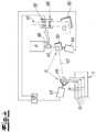
- the figuresshow a device for producing an adhesive tape.
- a band-shaped carrier 1which is fed from a supply unit 2 in a machine direction MR, which coincides with the longitudinal direction of the band-shaped carrier 1.
- the band-shaped carrier 1is a band-shaped textile carrier 1 and specifically a fabric, for example PA fabric. This is equipped with a one-sided adhesive coating 3 over its entire surface.
- the thus prefabricated band-shaped textile carrier 1is now cut in the machine direction MR using a laser unit 4, 5 in the longitudinal direction or machine direction MR into individual strip-shaped adhesive tapes 6, which can be seen on the output side.
- Laser unit 4, 5introduces cutting edges 7 into the band-shaped carrier in the longitudinal direction or machine direction MR, as can be seen from the top view of the band-shaped carrier 1.
- laser units 4, 5are now realized. To distinguish the individual laser units 4, 5, they are each marked with an index in the sense of 4 1 , 5 1 ; 4 2 and 5 2 and finally 4 3 , 5 3 and can thus be distinguished from each other. This can be seen from the Figures 2 and 3 .
- These multiple laser units 4, 5 or 4 1 , 5 1 ; 4 2 , 5 2 and 4 3 , 5 3now ensure that the band-shaped textile carrier 1 is processed in associated longitudinal segments 8 1 , 8 2 and 8 3 and is equipped with the previously mentioned cutting edges 7.
- the overall designis such that the laser unit 4 1 , 5 1 ensures the processing of the longitudinal segment 8 1.
- the laser unit 4 2 , 5 2belongs to the longitudinal segment 8 2 and the laser unit 4 3 , 5 3 processes the longitudinal segment 8 3 .
- the longitudinal segments 8 1 , 8 2 and 8 3each extend as strips in the longitudinal direction of the band-shaped textile carrier 1, that is to say in the machine direction MR. It can also be seen that the individual longitudinal segments 8 1 , 8 2 and 8 3 are divided into sections 9 in the longitudinal direction or machine direction MR in question.
- the individual longitudinal segments 8 1 , 8 2 and 8 3are each connected to one another without any gaps and together extend over the entire width B of the band-shaped carrier 1.
- This width B of the band-shaped carrier 1can be several centimeters up to 1 m or even more.
- the band-shaped carrier 1is received on the storage unit 2 designed as a winding drum and finally fed via individual deflection rollers 10 to the laser unit 4, 5 or the several laser units 4 1 , 5 1 ; 4 2 , 5 2 and 4 3 , 5 3
- the strip-shaped adhesive tapes 6 produced in this wayare divided up, for example, and wound up using take-up rolls 11 and made into spiral-shaped adhesive tape rolls, for example.
- the laser unit 4 1 , 5 1ensures that three cutting edges 7 are generated in the associated longitudinal segment 8 1 , so that in this way and on the output side a total of four strip-shaped adhesive tapes 6 are created from the relevant longitudinal segment 8 1 of the band-shaped carrier 1.
- a similar procedurecan be followed for the other longitudinal segments 8 2 and 8 3 .
- the laser unit 4 1 , 5 1 ; 4 2 , 5 2 and 4 3 , 5 3is each equipped with a laser source 4 1 , 4 2 , 4 3 and an associated beam deflection unit 5 1 , 5 2 , 5 3.
- the laser source 4 1 , 4 2 , 4 3is each oriented transversely to the machine direction MR.
- the beam deflection unit 5 1 , 5 2 , 5 3the beam emanating from the laser unit 4 and in particular in the Figure 4 to be recognized laser beam 12 for producing the individual strip-shaped adhesive tapes 6 in the associated longitudinal segment 8 1 , 8 2 , 8 3 is deflected in the longitudinal direction in order to produce the individual cutting edges 7 of predetermined length L.
- the designis such that with the help of the beam deflection unit 5 or 5 1 , 5 2 , 5 3 in the associated longitudinal segment 8 1 , 8 2 , 8 3 , first of all a cutting edge 7 is produced in the section 9 with the predetermined length L.
- the section 9 and consequently the cutting edge 7may have a length L of, for example, 50 mm to 100 mm or even more.
- the laser beam 12jumps to the second cutting edge 7 and produces this with the same length L until, according to the exemplary embodiment, all three cutting edges 7 in the longitudinal segment 8 1 and the section 9 there have been produced with the length L.
- the beam deflection unit 5 or generally the laser unit 4, 5each produces parallel cutting edges 7 of the same length L in the associated longitudinal segment 8 1 , 8 2 and 8 3 .
- the number of cutting edges 7specifies the number of adhesive tapes 6 produced in this way on the output side.
- the designis such that the laser unit 4, 5 or the beam deflection unit 5 in the respective longitudinal segment 8 1 , 8 2 and 8 3 produces the parallel cutting edges 7 of the predetermined length L adjacent to one another in the machine direction MR.
- the speed of the beam deflection unit 5must be at least three times the speed of the strip-shaped carrier 1.
- the designis such that the parallel cutting edges 7 connect to one another without any offset.
- the feed of the strip-shaped carrier 1 in the machine direction MRensures that the cutting edges 7 in the longitudinal segment 8 1 can then be produced in the subsequent second section 9.
- the parallel cutting edges 7connect to one another without any offset.
- the designis such that the speed of the strip-shaped carrier 1 and that of the beam deflection unit 5 1 in the example case of the longitudinal segment 8 1 are adapted to one another.
- a central control unit 13ensures the adjustment.
- the central control unit 13receives signals from a sensor 20, with the help of which the web speed of the band-shaped textile carrier 1 is measured and transmitted to the central control unit 13.
- the central control unit 13is connected to the individual laser units 4 1 , 5 1 ; 4 2 , 5 2 and 4 3 , 5 3 in order to control them accordingly so that they can be used to produce the longitudinal edges 7 in the associated section 9 of the corresponding longitudinal segments 8 1 , 8 2 , 8 3.
- the further possibility of using the central control unit 13to control a drive for the textile carrier 1 to adjust its speed in the machine direction MR depending on the signals from the sensor 20.
- the beam deflection unit 5is equipped with at least two deflection mirrors 14, 15.
- the two deflection mirrors 14, 15can be divided into two mutually vertical planes.
- each deflection mirror 14, 15is equipped with an associated galvanometer scanner 16, 17, which in turn are controlled and actuated by means of the central control unit 13.
- the laser beam 12is focused on the plane of the band-shaped carrier 1.
- an expansion optic 18is implemented, with the help of which a refocusing of the laser beam 12 is possible.
- the expansion optic 18has a lens 19 that can be moved by motor in the direction of the laser beam 12.
- the lens 19, like the two galvanometer scanners 16, 17,is also connected to the central control unit 13.
Landscapes
- Engineering & Computer Science (AREA)
- Physics & Mathematics (AREA)
- Optics & Photonics (AREA)
- Mechanical Engineering (AREA)
- Plasma & Fusion (AREA)
- Chemical & Material Sciences (AREA)
- Organic Chemistry (AREA)
- Life Sciences & Earth Sciences (AREA)
- Forests & Forestry (AREA)
- Chemical Kinetics & Catalysis (AREA)
- Toxicology (AREA)
- General Health & Medical Sciences (AREA)
- Health & Medical Sciences (AREA)
- Laser Beam Processing (AREA)
- Treatment Of Fiber Materials (AREA)
- Adhesive Tapes (AREA)
- Package Closures (AREA)
Description
Translated fromGermanDie Erfindung betrifft ein Verfahren und eine zugehörige Vorrichtung zur Herstellung eines Klebebandes, wonach ein bandförmiger sowie mit einer Klebebeschichtung ausgerüsteter textiler Träger ausgehend von einer Vorratseinheit zugeführt wird, wonach ferner der bandförmige Träger mithilfe einer Lasereinheit in Längsrichtung zu den einzelnen Klebebändern geschnitten wird, und wonach mehrere Lasereinheiten vorgesehen sind, die in einzelnen Längssegmenten des bandförmigen Trägers die jeweiligen Klebebänder erzeugen.The invention relates to a method and an associated device for producing an adhesive tape, according to which a tape-shaped textile carrier provided with an adhesive coating is fed from a storage unit, after which the tape-shaped carrier is further cut longitudinally into the individual adhesive tapes using a laser unit, and after which several laser units are provided which produce the respective adhesive tapes in individual longitudinal segments of the tape-shaped carrier.
Typischerweise erfolgt die Herstellung von Klebebändern derart, dass der bandförmige sowie mit der Klebebeschichtung ausgerüstete textile Träger von der Vorratseinheit einer Schneideinrichtung zugeführt wird. Die Schneideinrichtung ist beispielsweise mit rotierenden Messern ausgerüstet, so dass auf diese Weise der bandförmige Träger in die einzelnen Klebebänder geschnitten wird, die dann für sich genommen aufgerollt und weiter konfektioniert werden. Eine solche Vorgehensweise wird unter anderem und ganz generell im Stand der Technik nach der
Daneben wird im Stand der Technik aber auch grundsätzlich schon so vorgegangen, dass das Schneiden der einzelnen Klebebänder aus dem bandförmigen textilen Träger mithilfe einer Ultraschalleinheit und/oder einer Lasereinheit vorgenommen werden kann, wie dies die vorerwähnte und gattungsbildende Veröffentlichung generell beschreibt. Dabei ist eine Lasereinheit mit dem grundsätzlichen Vorteil ausgerüstet, dass beispielsweise bei einem Wechsel des zu konfektionierenden Klebebandes bzw. einer Änderung seiner Breite keine aufwendigen Einstellmaßnahmen erforderlich sind, wie dies bei rotierenden Messern notwendig ist. Denn hier sind entsprechende mechanische Verstellungen unabdingbar, wohingegen bei einer Lasereinheit die Einstellung ohne mechanischen Eingriff verändert werden kann.In addition, the state of the art also basically provides for the cutting of the individual adhesive tapes from the tape-shaped textile carrier using an ultrasound unit and/or a laser unit, as generally described in the aforementioned and generic publication. A laser unit is equipped with the fundamental advantage that, for example, when changing the adhesive tape to be manufactured or changing its width, no complex adjustment measures are required, as is necessary with rotating knives. This is because Corresponding mechanical adjustments are indispensable, whereas with a laser unit the setting can be changed without mechanical intervention.
Im Rahmen des ebenfalls einschlägigen Standes der Technik nach der
Beim gattungsbildenden Stand der Technik nach der
Ferner befasst sich der weitere Stand der Technik nach der
Schließlich beschäftigt sich der
Der Stand der Technik hat sich grundsätzlich bewährt, stößt jedoch dann an Grenzen, wenn eine Vielzahl an Klebebändern aus einem bandförmigen textilen Träger hergestellt werden soll. Außerdem lassen sich bisher keine ausreichenden Produktionsgeschwindigkeiten in der Praxis darstellen, um preislich wettbewerbsfähige Klebebänder mit dieser Technik realisieren zu können. Hier setzt die Erfindung ein.The state of the art has proven itself in principle, but reaches its limits when a large number of adhesive tapes are to be produced from a textile backing in the form of a band. In addition, sufficient production speeds have not yet been achieved in practice to be able to produce adhesive tapes that are competitively priced using this technology. This is where the invention comes in.
Der Erfindung liegt das technische Problem zugrunde, ein Verfahren und eine Vorrichtung zur Herstellung von Klebebändern der eingangs beschriebenen Ausprägung so weiterzuentwickeln, dass insgesamt die Produktionsgeschwindigkeit gegenüber bisherigen Vorgehensweisen erhöht ist und dadurch wettbewerbsfähige Produkte zur Verfügung stehen.The invention is based on the technical problem of further developing a method and a device for producing adhesive tapes of the type described above in such a way that the overall production speed is increased compared to previous procedures and thus competitive products are available.
Zur Lösung dieser technischen Problemstellung ist ein gattungsgemäßes Verfahren im Rahmen der Erfindung dadurch gekennzeichnet, dass eine zentrale Steuereinheit eingesetzt wird, um sämtliche Lasereinheiten hiermit gemeinsam derart ansteuern zu können, dass in jedem Längssegment mehrere Klebebänder mithilfe der zugehörigen Lasereinheit geschnitten werden und dazu die jeweilige Lasereinheit mit einer Laserquelle sowie einer Strahlablenkeinheit ausgerüstet ist, wobei die Strahlablenkeinheit den von der Lasereinheit ausgehenden Laserstrahl zur Erzeugung der einzelnen Klebebänder im zugehörigen Längssegment jeweils in Längsrichtung zur Realisierung mehrerer Schnittkanten vorgegebener Länge ablenkt, wobei ferner die Geschwindigkeit des bandförmigen Trägers und diejenige der Strahlablenkeinheit aneinander angepasst sind und dem von der Vorratseinheit zugeführten bandförmigen Träger ein Sensor zur Geschwindigkeitsmessung zugeordnet ist, um die Geschwindigkeit des bandförmigen Trägers zu erfassen, und wobei ein Geschwindigkeitssignal des Sensors von der zentralen Steuereinheit verarbeitet und mit der Geschwindigkeit zum Ansteuern der Strahlablenkeinheit synchronisiert wird.To solve this technical problem, a generic method within the scope of the invention is characterized in that a central control unit is used in order to be able to control all laser units together in such a way that several adhesive tapes are cut in each longitudinal segment using the associated laser unit and for this purpose the respective laser unit is equipped with a laser source and a beam deflection unit, wherein the beam deflection unit deflects the laser beam emanating from the laser unit to produce the individual adhesive tapes in the associated longitudinal segment in the longitudinal direction to create several cutting edges of a predetermined length, wherein the speed of the band-shaped carrier and that of the beam deflection unit are also adapted to one another and a sensor for measuring the speed is connected to the band-shaped carrier fed from the supply unit. is assigned to detect the speed of the band-shaped carrier, and wherein a speed signal of the sensor is processed by the central control unit and synchronized with the speed for controlling the beam deflection unit.
Die Erfindung greift also zunächst einmal und ausdrücklich nicht auf eine (einzige) Lasereinheit zurück, wie dies der Stand der Technik in diesem Kontext lehrt und vorgibt. Vielmehr kommen mehrere Lasereinheiten zum Einsatz, das heißt zwei oder mehr Lasereinheiten. Dadurch kann grundsätzlich die Produktionsgeschwindigkeit erhöht werden. Das alles gelingt überraschenderweise auch vor dem Hintergrund, dass Lasereinheiten typischerweise kostenintensiv sind.First of all, the invention expressly does not rely on a (single) laser unit, as the state of the art teaches and specifies in this context. Instead, several laser units are used, i.e. two or more laser units. This can fundamentally increase the production speed. Surprisingly, all of this is also possible given that laser units are typically expensive.
Die Erfindung hat jedoch erkannt, dass der Rückgriff auf zwei oder mehr Lasereinheiten bei entsprechend breitem bandförmigen Träger die Möglichkeit eröffnet, eine Vielzahl an Klebebändern mithilfe der mehreren Lasereinheiten gleichzeitig und parallel schneiden zu können. Durch diese erhöhte Produktionsgeschwindigkeit werden die anfänglich hohen Investitionskosten kompensiert, was so generell nicht zu erwarten war.However, the invention has recognized that the use of two or more laser units with a correspondingly wide tape-shaped carrier opens up the possibility of cutting a large number of adhesive tapes simultaneously and in parallel using the multiple laser units. This increased production speed compensates for the initially high investment costs, which was generally not to be expected.
Die gewählte Vorgehensweise der Erfindung ist dabei nach wie vor mit dem Vorteil ausgerüstet, dass mithilfe der jeweiligen Lasereinheit insbesondere die Breite des auf diese Weise erzeugten Klebebandes einfach und schnell variiert werden kann. Dazu ist es in der Regel lediglich erforderlich, eine entsprechende und den jeweiligen Längsschnitt erzeugende Strahlablenkeinheit anders anzusteuern. Das geschieht meistens mithilfe einer programmierbaren Steuereinheit. Auf diese Weise besteht sogar die Möglichkeit, aus dem bandförmigen Träger Klebebänder mit unterschiedlicher Breite in einem Zug und in der Maschinenlängsrichtung schneiden zu können. Dadurch ist das erfindungsgemäße Verfahren nicht nur durch eine gegenüber dem Stand der Technik erhöhte Produktionsgeschwindigkeit gekennzeichnet, sondern lassen sich bedarfsweise Klebebänder praktisch beliebiger Breite gleichzeitig realisieren, die an den jeweiligen Bedarf optimal angepasst werden können. Es wird also eine besondere Flexibilität im Hinblick auf die erzeugten jeweiligen Mengen zur Verfügung gestellt.The chosen approach of the invention is still equipped with the advantage that, with the help of the respective laser unit, the width of the adhesive tape produced in this way can be varied easily and quickly. To do this, it is usually only necessary to control a corresponding beam deflection unit that produces the respective longitudinal cut differently. This is usually done with the help of a programmable control unit. In this way, it is even possible to cut adhesive tapes of different widths from the band-shaped carrier in one go and in the longitudinal direction of the machine. This makes it possible to The process according to the invention is not only characterized by a higher production speed than the prior art, but also allows adhesive tapes of practically any width to be produced simultaneously, which can be optimally adapted to the respective requirements. This provides particular flexibility with regard to the respective quantities produced.
Dabei versteht es sich, dass grundsätzlich sogar im jeweiligen Längssegment Klebebänder unterschiedlicher Breite produziert werden können. Daneben ist es auch denkbar, im jeweiligen Längssegment Klebebänder gleicher Breite herzustellen, wobei von Längssegment zu Längssegment mit unterschiedlicher Breite der erzeugten Klebebänder gearbeitet wird. Das Längssegment wird dabei von der zugehörigen Lasereinheit abgedeckt und korrespondiert zu einem Streifen des bandförmigen Trägers in Längsrichtung vorgegebener Breite.It goes without saying that, in principle, adhesive tapes of different widths can be produced in each longitudinal segment. It is also conceivable to produce adhesive tapes of the same width in each longitudinal segment, with the adhesive tapes produced having different widths from longitudinal segment to longitudinal segment. The longitudinal segment is covered by the associated laser unit and corresponds to a strip of the tape-shaped carrier of a predetermined width in the longitudinal direction.
Dabei wird meistens so vorgegangen, dass die einzelnen Längssegmente abstandsfrei aneinander anschließen. Grundsätzlich können die einzelnen der jeweiligen Lasereinheit zugeordneten Längssegmente aber auch beabstandet zueinander in der Längsrichtung bzw. Maschinenrichtung des bandförmigen Trägers verlaufen. Sofern die Längssegmente abstandsfrei aneinander anschließen, erstrecken sie sich in der Regel über die gesamte Breite des bandförmigen Trägers und decken diesen praktisch vollständig ab.The procedure is usually such that the individual longitudinal segments are connected to one another without any gaps. In principle, however, the individual longitudinal segments assigned to the respective laser unit can also be spaced apart from one another in the longitudinal direction or machine direction of the strip-shaped carrier. If the longitudinal segments are connected to one another without any gaps, they usually extend across the entire width of the strip-shaped carrier and cover it practically completely.
Außerdem wird erfindungsgemäß so vorgegangen, dass in jedem Längssegment mehrere Klebebänder mithilfe der zugehörigen Lasereinheit geschnitten werden. Beispielsweise ist es denkbar, dass mit der zugehörigen Lasereinheit beispielsweise drei bis zehn Klebebänder in dem korrespondierenden Längssegment erzeugt werden. Wenn an dieser Stelle dann noch und beispielhaft drei Lasereinheiten zum Einsatz kommen, können auf diese Weise und zugleich 30 Klebebänder parallel produziert werden. Das gilt selbstverständlich nur beispielhaft und hängt auch davon ab, wie breit der von der Vorratseinheit zugeführte bandförmige Träger ausgelegt ist. Meistens geht man hier von einer Rollenbreite (bezogen auf die Mutterrolle) aus, die im Minimum 350 mm beträgt.In addition, the invention proceeds in such a way that several adhesive tapes are cut in each longitudinal segment using the associated laser unit. For example, it is conceivable that three to ten adhesive tapes are produced in the corresponding longitudinal segment using the associated laser unit. If three laser units are then used at this point, for example, In this way, 30 adhesive tapes can be produced in parallel. This is of course only an example and also depends on how wide the tape-shaped carrier fed from the storage unit is. In most cases, a roll width (relative to the parent roll) of at least 350 mm is assumed.
Wie bereits erläutert, werden die Klebebänder im Allgemeinen im jeweiligen und zur Lasereinheit gehörigen Längssegment mit übereinstimmender Breite geschnitten. Selbstverständlich kann im betreffenden Längssegment auch mit voneinander abweichender Breite gearbeitet werden. Ebenso liegt es im Rahmen der Erfindung, Klebebänder mit jeweils übereinstimmender Breite im jeweiligen Längssegment zu erzeugen und die Breite von Längssegment zu Längssegment zu variieren. Außerdem wird meistens so vorgegangen, dass der bandförmige Träger in Querrichtung in die Längssegmente jeweils gleicher Breite unterteilt wird. Genauso gut kann natürlich auch mit Längssegmenten unterschiedlicher Breite in der Querrichtung gearbeitet werden.As already explained, the adhesive tapes are generally cut in the respective longitudinal segment belonging to the laser unit with the same width. Of course, it is also possible to work with different widths in the respective longitudinal segment. It is also within the scope of the invention to produce adhesive tapes with the same width in the respective longitudinal segment and to vary the width from longitudinal segment to longitudinal segment. In addition, the procedure is usually such that the band-shaped carrier is divided in the transverse direction into longitudinal segments of the same width. Of course, it is also possible to work with longitudinal segments of different widths in the transverse direction.
Auf diese Weise wird jeweils eine Vielzahl an Klebebändern aus dem bandförmigen Träger durch die beschriebenen Längsschnitte erzeugt. Die einzelnen Klebebänder können anschließend zu Klebebandrollen konfektioniert werden. Dabei ist es generell denkbar, dass der bandförmige textile Träger von vornherein mit der Klebebeschichtung ausgerüstet ist. Dazu mag die Klebebeschichtung vollflächig auf den textilen Träger aufgebracht sein. Grundsätzlich ist natürlich auch eine Streifenbeschichtung möglich.In this way, a large number of adhesive tapes are produced from the band-shaped carrier through the described longitudinal cuts. The individual adhesive tapes can then be made into adhesive tape rolls. It is generally conceivable that the band-shaped textile carrier is equipped with the adhesive coating from the outset. The adhesive coating can be applied to the entire surface of the textile carrier. In principle, strip coating is of course also possible.
Darüber hinaus liegt es im Rahmen der Erfindung, den unbeschichteten bandförmigen textilen Träger zu den einzelnen Klebebändern mithilfe der Lasereinheit zu schneiden und erst im Anschluss daran die einzelnen Klebebänder mit der Klebebeschichtung auszurüsten. Das kann vollflächig geschehen. Im Allgemeinen wird man bei einer solchen Vorgehensweise jedoch so arbeiten, dass auf die mithilfe der Lasereinheit geschnittenen einzelnen Klebebänder eine Streifenbeschichtung des Klebemittels aufgetragen wird. In diesem Zusammenhang hat es sich bewährt, wenn als Klebemittel ein Hotmeltkleber bzw. Schmelzhaftkleber auf Acrylatbasis zum Einsatz kommen. Dabei mag die Beschichtung mit einer entsprechend schmal ausgerüsteten Düse als Streifenbeschichtung auf das betreffende Klebeband aufgebracht werden. Grundsätzlich kann auch mit einer Maske gearbeitet werden, um den Schmelzhaftkleber als Streifen auf das zuvor geschnittene Klebeband aufzubringen.Furthermore, it is within the scope of the invention to cut the uncoated, tape-shaped textile carrier into individual adhesive tapes using the laser unit and only then to equip the individual adhesive tapes with the adhesive coating. This can be done over the entire surface In general, however, such a procedure will involve applying a strip coating of the adhesive to the individual adhesive tapes cut using the laser unit. In this context, it has proven to be effective to use a hot melt adhesive or acrylate-based hot melt pressure sensitive adhesive as the adhesive. The coating can be applied to the relevant adhesive tape as a strip coating using a suitably narrow nozzle. In principle, a mask can also be used to apply the hot melt pressure sensitive adhesive as a strip to the previously cut adhesive tape.
Für den textilen Träger sind grundsätzlich jedwede Textilien geeignet, so beispielsweise Vliese, Gewebe, Gewirke oder auch Mischformen. Meistens wird an dieser Stelle mit einem Gewebeträger gearbeitet. Denkbar sind hier beispielsweise PA (Polyamid)-Gewebe, PET (Polyethylentheraphthalat)-Gewebe usw. Der textile Träger greift dabei typischerweise auf Kunststofffasern zurück. Auf diese Weise werden jeweils fusselfreie Schnittkanten erzeugt. Denn beim Schneidprozess mithilfe der Lasereinheit kommt es - zumindest temporär - dazu, dass die Kunststofffasern im Bereich der Schnittkante eingeschmolzen werden und so saubere und fusselfreie Schnittkanten erzeugt werden.Basically, any textile is suitable for the textile carrier, such as fleece, fabric, knitted fabric or even mixed forms. Most of the time, a fabric carrier is used here. Examples of possible materials here are PA (polyamide) fabric, PET (polyethylene terephthalate) fabric, etc. The textile carrier typically uses plastic fibers. This creates lint-free cut edges. During the cutting process using the laser unit, the plastic fibers in the area of the cut edge are melted - at least temporarily - and clean and lint-free cut edges are created.
Das gilt insbesondere für den Fall, dass mit einer Lasereinheit gearbeitet wird, die im Infraroten emittiert. Tatsächlich haben sich an dieser Stelle insbesondere CO2-Laser als günstig erwiesen, die typischerweise bei ca. 10,6 µm Wellenlänge emittieren. Eine solche Wellenlänge wird besonders gut von den meistens schwarzen textilen Trägern absorbiert und in Wärme umgesetzt, so dass es im Bereich der Schnittkanten zum zumindest teilweisen Verdampfen des Materials und einem Verschmelzen kommt. Die Leistung der treffenden Lasereinheit kann dabei grundsätzlich und nur beispielhaft bis zu 1 kW oder bis zu 2 kW oder noch mehr betragen. Außerdem kann die Lasereinheit kontinuierlich oder gepulst betrieben werden.This is especially true if a laser unit is used that emits in the infrared. In fact, CO2 lasers have proven to be particularly suitable for this purpose, as they typically emit at a wavelength of around 10.6 µm. This wavelength is particularly well absorbed by the mostly black textile supports and converted into heat, so that the material at least partially evaporates and melts in the area of the cutting edges. The power of the laser unit used can generally and only as an example be up to 1 kW or up to to 2 kW or even more. In addition, the laser unit can be operated continuously or in pulsed mode.
Erfindungsgemäß ist die Lasereinheit mit der Laserquelle sowie der Strahlablenkeinheit ausgerüstet. Außerdem ist zusätzlich noch die Steuereinheit realisiert. Da erfindungsgemäß mit mehreren Lasereinheiten gearbeitet wird, wird die zentrale Steuereinheit eingesetzt, um die sämtlichen Lasereinheiten hiermit gemeinsam ansteuern zu können. Die jeweilige Strahlablenkeinheit sorgt ihrerseits dafür, dass der von der Lasereinheit ausgehende Laserstrahl zur Erzeugung der einzelnen Klebebänder im zugehörigen Längssegment jeweils in Längsrichtung abgelenkt wird, und zwar zur Realisierung mehrerer Schnittkanten vorgegebener Länge. Dabei wird regelmäßig so vorgegangen, dass die Strahlablenkeinheit jeweils parallele Schnittkanten gleicher Länge im Längssegment erzeugt. Das heißt, das Längssegment kann in einzelne Abschnitte unterteilt werden. Der einzelne Abschnitt ist dabei durch die parallelen Schnittkanten gleicher Länge charakterisiert. In diesem Zusammenhang wird dann meistens so vorgegangen, dass die Anzahl der Schnittkanten im betreffenden Abschnitt der Anzahl der Klebebänder im Längssegment entspricht.According to the invention, the laser unit is equipped with the laser source and the beam deflection unit. The control unit is also implemented. Since the invention works with several laser units, the central control unit is used in order to be able to control all of the laser units together. The respective beam deflection unit in turn ensures that the laser beam emanating from the laser unit is deflected in the longitudinal direction to produce the individual adhesive tapes in the associated longitudinal segment, namely to produce several cutting edges of a predetermined length. The procedure is usually such that the beam deflection unit produces parallel cutting edges of the same length in the longitudinal segment. This means that the longitudinal segment can be divided into individual sections. The individual section is characterized by the parallel cutting edges of the same length. In this context, the procedure is usually such that the number of cutting edges in the section in question corresponds to the number of adhesive tapes in the longitudinal segment.
Um nun Klebebänder unterschiedlicher Länge erzeugen zu können, sorgt die Strahlablenkeinheit dafür, dass im jeweiligen Längssegment die parallelen Schnittkanten vorgegebener Länge jeweils in Maschinenrichtung aneinander anschließen. Das heißt, mithilfe der Strahlablenkeinheit wird zunächst ein Abschnitt im Längssegment erzeugt. Im betreffenden Abschnitt sind die parallelen Schnittkanten vorgegebener Länge realisiert. Bei dieser Länge mag es sich um beispielsweise 50 mm oder 100 mm oder noch mehr handeln.In order to be able to produce adhesive tapes of different lengths, the beam deflection unit ensures that the parallel cutting edges of a specified length are connected to one another in the machine direction in the respective longitudinal segment. This means that a section is first created in the longitudinal segment using the beam deflection unit. The parallel cutting edges of a specified length are created in the section in question. This length may be, for example, 50 mm or 100 mm or even more.
Da Klebebänder in der Regel über eine Länge von mehreren Metern verfügen, sorgt nun die Strahlablenkeinheit dafür, dass die einzelnen Abschnitte aneinander anschließen. Zu diesem Zweck werden die parallelen Schnittkanten vorgegebener Länge jeweils in Maschinenrichtung aneinander anschließend mithilfe der Strahlablenkeinheit erzeugt. Das geschieht generell derart, dass die parallelen Schnittkanten versatzfrei aneinander anschließen. Es ist grundsätzlich aber auch möglich, dass die parallelen Schnittkanten mit Versatz aneinander anschließen. So wird man beispielsweise dann vorgehen, wenn am Ende des zu erzeugenden Klebebandes auf ein Klebeband anderer Breite umgestellt werden soll.Since adhesive tapes are usually several meters long, the beam deflection unit ensures that the individual sections are connected to one another. To do this, the parallel cut edges of a specified length are then created in the machine direction using the beam deflection unit. This is generally done in such a way that the parallel cut edges connect to one another without any offset. However, it is also possible for the parallel cut edges to connect to one another with an offset. This is the procedure, for example, if you want to switch to an adhesive tape of a different width at the end of the adhesive tape to be produced.
Außerdem wird erfindungsgemäß so vorgegangen, dass die Geschwindigkeit des bandförmigen Trägers und diejenige der Strahlablenkeinheit aneinander angepasst sind. Um die Geschwindigkeit des bandförmigen Trägers zu erfassen, wird dem von der Vorratseinheit zugeführten bandförmigen Träger ein Sensor zur Geschwindigkeitsmessung zugeordnet werden. Bei diesem Sensor zur Geschwindigkeitsmessung mag es sich um eine Friktionsrolle handeln, also eine an die Oberfläche des bandförmigen Trägers angelegte Rolle, die durch die Bewegung des bandförmigen Trägers in Maschinenrichtung in Rotationen versetzt wird. Die Rotationen der Rolle korrespondieren zu dem Geschwindigkeitssignal, welches von der zentralen Steuereinheit verarbeitet und mit der Geschwindigkeit zur Ansteuerung der Strahlablenkeinheit synchronisiert wird.In addition, the invention proceeds in such a way that the speed of the band-shaped carrier and that of the beam deflection unit are adapted to one another. In order to detect the speed of the band-shaped carrier, a speed measuring sensor is assigned to the band-shaped carrier fed from the storage unit. This speed measuring sensor may be a friction roller, i.e. a roller placed on the surface of the band-shaped carrier, which is set in rotation by the movement of the band-shaped carrier in the machine direction. The rotations of the roller correspond to the speed signal, which is processed by the central control unit and synchronized with the speed for controlling the beam deflection unit.
Es ist alternativ oder zusätzlich aber auch denkbar, dass der bandförmige Träger über beispielsweise in regelmäßigen Abständen vorhandene Markierungen verfügt, die mithilfe des Sensors zur Geschwindigkeitsmessung erfasst und zu einem entsprechenden Geschwindigkeitssignal beim Durchlauf des bandförmigen Trägers in der Maschinenrichtung korrespondieren. Auch in diesem Fall wird das Signal des Sensors von der zentralen Steuereinheit verarbeitet und mit der Geschwindigkeit zur Ansteuerung der Strahlablenkeinheit synchronisiert.Alternatively or additionally, it is also conceivable that the band-shaped carrier has markings, for example at regular intervals, which are detected by the speed measurement sensor and correspond to a corresponding speed signal when the band-shaped carrier passes through in the machine direction. In this case, the sensor signal is processed by the central control unit and synchronized with the speed to control the beam deflection unit.
Die Synchronisation der Geschwindigkeit des bandförmigen Trägers einerseits mit der Strahlablenkeinheit andererseits wird seitens der zentralen Steuereinheit so vorgenommen, dass die Strahlablenkeinheit beispielsweise der Geschwindigkeit des bandförmigen Trägers in der Maschinenrichtung folgen kann. Diese Geschwindigkeit mag mehrere 10 m/min betragen, beispielsweise bis zu 60 m/min oder noch mehr. Jedenfalls ist es erforderlich, dass bei beispielsweise einer Geschwindigkeit des bandförmigen Trägers in der Maschinenrichtung von 50 m/min auch die Strahlablenkeinheit so schnell angesteuert wird oder werden kann, dass im Beispielfall die zehn Schnittkanten im zugehörigen Längssegment auch jeweils von Abschnitt zu Abschnitt erzeugt werden können. Das setzt voraus, dass jede einzelne Schnittkante von der Ablenkeinheit mit zumindest der zehnfachen Geschwindigkeit im Vergleich zur Geschwindigkeit des bandförmige Trägers produziert wird, weil die Strahlablenkeinheit dafür sorgt, dass der Laserstrahl innerhalb des Längssegmentes von Schnittkante zu Schnittkante springt.The synchronization of the speed of the strip-shaped carrier on the one hand with the beam deflection unit on the other hand is carried out by the central control unit in such a way that the beam deflection unit can, for example, follow the speed of the strip-shaped carrier in the machine direction. This speed may be several 10 m/min, for example up to 60 m/min or even more. In any case, if the speed of the strip-shaped carrier in the machine direction is, for example, 50 m/min, the beam deflection unit must also be or can be controlled so quickly that, in the example case, the ten cutting edges in the associated longitudinal segment can also be produced from section to section. This requires that each individual cutting edge is produced by the deflection unit at at least ten times the speed of the strip-shaped carrier, because the beam deflection unit ensures that the laser beam jumps from cutting edge to cutting edge within the longitudinal segment.
Zu diesem Zweck ist die Strahlablenkeinheit in der Regel mit wenigstens zwei Umlenkspiegeln ausgerüstet, die in zwei zueinander senkrecht stehenden Ebenen verschwenkbar sind. Außerdem wird zum Verschwenken des betreffenden Umlenkspiegels in der Regel ein sogenannter Galvanometer-Scanner eingesetzt. Als Folge hiervon ist die Strahlablenkeinheit typischerweise als dreiachsiger Galvanometer-Scanner ausgebildet, ermöglicht also Schnitte insbesondere in der Ebene und in praktisch beliebiger Längs- und Querrichtung. Die Längsrichtung fällt dabei mit der Maschinenrichtung zusammen, während die Querrichtung hierzu quer verläuft. - Gegenstand der Erfindung ist auch eine zugehörige Vorrichtung, wie sie im Anspruch 12 ff. beschrieben wird.For this purpose, the beam deflection unit is usually equipped with at least two deflection mirrors that can be pivoted in two mutually perpendicular planes. In addition, a so-called galvanometer scanner is usually used to pivot the relevant deflection mirror. As a result, the beam deflection unit is typically designed as a three-axis galvanometer scanner, thus enabling cuts in particular in the plane and in practically any longitudinal and transverse direction. The longitudinal direction coincides with the machine direction, while the transverse direction runs transversely to it. - Subject of the The invention also relates to an associated device as described in
Nachfolgend wird die Erfindung anhand einer lediglich ein Ausführungsbeispiel darstellenden Zeichnung näher erläutert; es zeigen:
- Fig. 1
- die erfindungsgemäße Vorrichtung zur Herstellung eines Klebebandes in einer schematischen Übersicht zusammen mit einer prinzipiellen Aufsicht auf den bandförmigen Träger,
- Fig. 2
- die Vorrichtung perspektivisch in vergrößerter Ansicht,
- Fig. 3
- einen Ausschnitt aus der
Fig. 2 im Bereich der Lasereinheit und - Fig. 4
- die Strahlablenkeinheit schematisch und im Detail.
- Fig.1
- the device according to the invention for producing an adhesive tape in a schematic overview together with a basic plan view of the tape-shaped carrier,
- Fig.2
- the device in perspective in enlarged view,
- Fig.3
- an excerpt from the
Fig.2 in the area of the laser unit and - Fig.4
- the beam deflection unit schematically and in detail.
In den Figuren ist eine Vorrichtung zur Herstellung eines Klebebandes dargestellt. Zu diesem Zweck erkennt man zunächst einmal einen bandförmigen Träger 1 der von einer Vorratseinheit 2 ausgehend in einer Maschinenrichtung MR zugeführt wird, welche mit der Längsrichtung des bandförmigen Trägers 1 zusammenfällt. Bei dem bandförmigen Träger 1 handelt es sich um einen bandförmigen textilen Träger 1 und konkret um ein Gewebe, beispielsweise PA-Gewebe. Dieses ist mit einer einseitigen Klebebeschichtung 3 vollflächig ausgerüstet.The figures show a device for producing an adhesive tape. For this purpose, one can first see a band-shaped
Der solchermaßen vorkonfektionierte bandförmige textile Träger 1 wird nun in der Maschinenrichtung MR mithilfe einer Lasereinheit 4, 5 in der Längsrichtung bzw. Maschinenrichtung MR zu einzelnen streifenförmigen Klebebändern 6 geschnitten, die man ausgangsseitig erkennt. Dazu werden jeweils mithilfe der Lasereinheit 4, 5 in den bandförmigen Träger Schnittkanten 7 in der Längsrichtung bzw. Maschinenrichtung MR eingebracht, wie man anhand der Aufsicht auf den bandförmigen Träger 1 nachvollziehen kann.The thus prefabricated band-shaped
Erfindungsgemäß sind nun mehrere Lasereinheiten 4, 5 realisiert. Zur Unterscheidung der einzelnen Lasereinheiten 4, 5 sind diese jeweils mit einem Index im Sinne von 41, 51; 42 und 52 und schließlich 43, 53 gekennzeichnet und können so voneinander unterschieden werden. Das erkennt man anhand der
Die Längssegmente 81, 82 und 83 erstrecken sich jeweils als Streifen in Längsrichtung des bandförmigen textilen Trägers 1 das heißt in der Maschinenrichtung MR. Außerdem erkennt man, dass die einzelnen Längssegmente 81, 82 und 83 in der fraglichen Längsrichtung bzw. Maschinenrichtung MR in Abschnitte 9 unterteilt sind.The longitudinal segments 81 , 82 and 83 each extend as strips in the longitudinal direction of the band-shaped
Die einzelnen Längssegmente 81, 82 und 83 schließen jeweils abstandsfrei aneinander an und erstrecken sich zusammengenommen über die gesamte Breite B des bandförmigen Trägers 1. Diese Breite B des bandförmigen Trägers 1 kann mehrere Zentimeter bis zu 1 m oder noch mehr betragen. Tatsächlich wird der bandförmige Träger 1 auf der als Wickeltrommel ausgebildeten Vorratseinheit 2 aufgenommen und über einzelne Umlenkrollen 10 schließlich der Lasereinheit 4, 5 bzw. den mehreren Lasereinheiten 41, 51; 42, 52 und 43, 53 zugeführt. Nachdem mithilfe der Lasereinheiten 41, 51; 42, 52 und 43, 53 die einzelnen Längsschnitte bzw. Schnittkanten 7 in den bandförmigen Träger 1 eingebracht worden sind, werden die auf diese Weise erzeugten streifenförmigen Klebebänder 6 beispielhaft aufgeteilt und mithilfe von Aufnahmerollen 11 aufgewickelt und beispielsweise zu spiralförmigen Klebebandrollen konfektioniert.The individual longitudinal segments 81 , 82 and 83 are each connected to one another without any gaps and together extend over the entire width B of the band-shaped
Zuvor werden nun in jedem der drei dargestellten Längssegmente 81, 82 und 83 mehrere Klebebänder 6 mithilfe der zugehörigen Lasereinheit 41, 51; 42, 52 und schließlich 43, 53 geschnitten. Nach dem Ausführungsbeispiel sorgt die Lasereinheit 41, 51 dafür, dass im zugehörigen Längssegment 81 drei Schnittkanten 7 erzeugt werden, so dass auf diese Weise und ausgangsseitig insgesamt vier streifenförmige Klebebänder 6 aus dem betreffenden Längssegment 81 des bandförmigen Trägers 1 entstehen. Bei den übrigen Längssegmenten 82 und 83 kann vergleichbar vorgegangen werden. Es ist aber auch möglich, dass mithilfe der Lasereinheit 42, 52 im zugehörigen Längssegment 82 eine unterschiedliche Anzahl an Schnittkanten 7 produziert wird, so dass hieraus auch eine im Vergleich zum Längssegment 81 abweichende Anzahl an Klebebändern 6 ausgangsseitig resultiert. Das ist im Detail jedoch nicht dargestellt. Das heißt, die Klebebänder 6 werden im jeweiligen Längssegment 81, 82 und 83 mit jeweils übereinstimmender Breite geschnitten. Außerdem ist die Auslegung so getroffen, dass der bandförmige Träger 1 in Querrichtung Q, also senkrecht zur Maschinenrichtung bzw. Längsrichtung MR, in die Längssegmente 81, 82 und 83 jeweils gleicher Breite unterteilt ist.Beforehand, several
Anhand der
Tatsächlich mag der Abschnitt 9 und folglich die Schnittkante 7 über die Länge L von beispielsweise 50 mm bis 100 mm oder noch mehr verfügen. Nachdem die Lasereinheit 41, 51 die erste Schnittkante 7 im Längssegment 81 erzeugt hat, springt der Laserstrahl 12 zur zweiten Schnittkante 7 und erzeugt diese mit übereinstimmender Länge L, bis nach dem Ausführungsbeispiel die sämtlichen drei Schnittkanten 7 im Längssegment 81 und dem dortigen Abschnitt 9 mit der Länge L produziert worden sind. Das heißt, die Strahlablenkeinheit 5 bzw. allgemein die Lasereinheit 4, 5 produziert jeweils parallele Schnittkanten 7 gleicher Länge L im zugehörigen Längssegment 81, 82 und 83. Die Anzahl der Schnittkanten 7 gibt dabei die Anzahl der auf diese Weise produzierten Klebebänder 6 ausgangsseitig vor. Außerdem ist die Auslegung so getroffen, dass die Lasereinheit 4, 5 bzw. die Strahlablenkeinheit 5 im jeweiligen Längssegment 81, 82 und 83 die parallelen Schnittkanten 7 der vorgegebenen Länge L jeweils in der Maschinenrichtung MR aneinander anschließend erzeugt. Dabei muss die Geschwindigkeit der Strahlablenkeinheit 5 wenigstens das Dreifache im Vergleich zur Geschwindigkeit des bandförmigen Trägers 1 betragen.In fact, the section 9 and consequently the
Um nun insgesamt die streifenförmigen Klebebänder 6 mit einer Länge von mehreren Metern im Beispielfall ausgangsseitig zur Verfügung zu stellen und zu produzieren, ist die Auslegung so getroffen, dass die parallelen Schnittkanten 7 jeweils versatzfrei aneinander anschließen. Das heißt, sobald im Beispielfall die Lasereinheit 41, 51 im ersten Abschnitt 9 des Längssegmentes 81 die dort im Ausführungsbeispiel vorgesehenen und dargestellten drei Schnittkanten 7 mit der Länge L erzeugt hat, sorgt insgesamt der Vorschub des bandförmigen Trägers 1 in der Maschinenrichtung MR dafür, dass anschließend die Schnittkanten 7 im Längssegment 81 im daran anschließenden weiteren zweiten Abschnitt 9 produziert werden können. Dabei schließen die jeweils parallelen Schnittkanten 7 versatzfrei aneinander an. Außerdem ist die Auslegung so getroffen, dass die Geschwindigkeit des bandförmigen Trägers 1 und diejenige der Strahlablenkeinheit 51 im betrachteten Beispielfall des Längssegmentes 81 aneinander angepasst sind. Für die Anpassung sorgt eine zentrale Steuereinheit 13. Dazu erhält die zentrale Steuereinheit 13 Signale eines Sensors 20, mit dessen Hilfe die Bahngeschwindigkeit des bandförmigen textilen Trägers 1 gemessen und an die zentrale Steuereinheit 13 übermittelt wird. Außerdem ist die zentrale Steuereinheit 13 jeweils an die einzelnen Lasereinheiten 41, 51; 42, 52 und 43, 53 angeschlossen, um diese entsprechend anzusteuern, damit mit ihrer Hilfe die Längskanten 7 im zugehörigen Abschnitt 9 der korrespondierenden Längssegmente 81, 82, 83 hergestellt werden können. Nicht ausdrücklich dargestellt ist die weitere Möglichkeit, dass mithilfe der zentralen Steuereinheit 13 in Abhängigkeit der Signale des Sensors 20 ein Antrieb für den textilen Träger 1 zur Einstellung seiner Geschwindigkeit in der Maschinenrichtung MR angesteuert wird.In order to make the strip-shaped
Anhand der Detaildarstellung in der
In der
Neben einer Änderung der Fokussierung des Laserstrahls 12 mithilfe der Steuereinheit 13 ist diese schließlich noch in der Lage, eine Korrektur der Position des bandförmigen Trägers 1 in der Querrichtung Q vornehmen zu können. Dazu lassen sich beispielsweise einzelne oder sämtliche der Umlenkrollen 10 (sowie gegebenenfalls die Vorratseinheit 2) in ihrer Längsrichtung und damit in der Querrichtung Q mithilfe der Steuereinheit 13 im Bedarfsfall verfahren, um sicherzustellen, dass die einzelnen Schnittkanten 7 tatsächlich versatzfrei von Abschnitt 9 zu Abschnitt 9 aneinander anschließen. Nicht dargestellt ist die Möglichkeit, die Strahlablenkeinheit 5 jeweils mit beispielsweise Wasser zu kühlen, um eine maximale Positionsstabilität der Umlenkspiegel 14, 15 zu erreichen. Ebenfalls nicht wiedergegeben ist die Option, dass die zentrale Steuereinheit 13 an ein übergeordnetes Netzwerk, beispielsweise das Internet, angeschlossen ist, um auf diese Weise eine Fernüberwachung vornehmen zu können bzw. von außen Programme zur Ansteuerung der jeweiligen Lasereinheit 4, 5 einspielen zu können.In addition to changing the focus of the
Claims (12)
- Method for producing an adhesive tape (6), according to whicha web-like textile carrier (1) equipped with an adhesive coating (3) is fed from a storage unit (2), further according to whichthe web-like carrier (1) is cut longitudinally into the individual adhesive tapes (6) using a laser unit (4, 5), and according to whicha plurality of laser units (41, 51; 42, 52; 43, 53) are provided, which create the respective adhesive tapes (6) in individual longitudinal segments (81, 82, 83) of the web-like carrier (1),characterized in thata central control unit (13) is used to enable all of the laser units (41, 51; 42, 52; 43, 53) to be actuated therewith in such a way that multiple adhesive tapes (6) are cut in each longitudinal segment (81, 82, 83) with the aid of the associated laser unit (41, 51; 42, 52; 43, 53), and for this purposethe respective laser unit (41, 51; 42, 52; 43, 53) is equipped with a laser source (4) and a beam deflection unit (5), whereinthe beam deflection unit (5) deflects the laser beam (12) emitted by the laser unit (4) for producing the individual adhesive tapes (6) in the associated longitudinal segment (81, 82, 83), each in the longitudinal direction to create multiple cut edges (7) of predefined length, wherein furtherthe speed of the web-like carrier (1) and that of the beam deflection unit (5) are matched with one another, anda sensor (20) for speed measurement is assigned to the web-like carrier (1) that is fed from the storage unit (2) in order to detect the speed of the web-like carrier (1), and whereina speed signal from the sensor (20) is processed by the central control unit (13) and synchronised with the speed in order to actuate the beam deflection unit (5).
- Method according to Claim 1,characterized in that the individual longitudinal segments (81, 82, 83) adjoin one another without any spacing and extend over the entire width of the web-like carrier (1).
- Method according to Claim 1 or 2,characterized in that a plurality of adhesive tapes (6) are produced in each longitudinal segment (81, 82, 83) with the aid of the associated laser unit (41, 51; 42, 52; 43, 53) .
- Method according to any one of Claims 1 to 3,characterized in that the adhesive tapes (6) are cut with matching width in the respective longitudinal segment (81, 82, 83) .
- Method according to any one of Claims 1 to 4,characterized in that the web-like carrier (1) is subdivided in the transverse direction (Q) into the longitudinal segments (81, 82, 83), each having the same width.
- Method according to any one of Claims 1 to 5,characterized in that the beam deflection unit (5) produces parallel cut edges (7) of the same length (L) in each case in the longitudinal segment (81, 82, 83) .
- Method according to Claim 6,characterized in that the number of cut edges (7) determines the number of adhesive tapes (6) in the longitudinal segment (81, 82, 83).
- Method according to any one of Claims 1 to 7,characterized in that the beam deflection unit (5) creates the parallel cut edges (7) of predetermined length (L) adjacent to each other in the respective longitudinal segment (81, 82, 83), each in the machine direction (MR).
- Method according to Claim 8,characterized in that the parallel cut edges (7) adjoin each another without offset.
- Apparatus for producing adhesive tapes (6), in particular for carrying out the method according to any one of Claims 1 to 9,with a storage unit (2) for feeding a web-like textile carrier (1) equipped with an adhesive coating (3), andwith a laser unit (4, 5) for cutting the web-like carrier (1) in the longitudinal direction to form the individual adhesive strips (6), whereinseveral laser units (41, 51; 42, 52; 43, 53) are provided, which create the respective adhesive tapes (6) in individual longitudinal segments (81, 82, 83) of the web-like carrier (1),characterized in thata central control unit (13) is provided to enable all of the laser units (41, 51; 42, 52; 43, 53) to be actuated therewith together in such a way that multiple adhesive tapes (6) are cut in each longitudinal segment (81, 82, 83) with the aid of the associated laser unit (41, 51; 42, 52; 43, 53), and for this purposethe respective laser unit (41, 51; 42, 52; 43, 53) is equipped with a laser source (4) and a beam deflection unit (5), whereinthe beam deflection unit (5) deflects the laser beam (12) emitted by the laser unit (4) for producing the individual adhesive tapes (6) in the associated longitudinal segment (81, 82, 83), each in the longitudinal direction to create multiple cut edges (7) of predefined length, wherein furtherthe speed of the web-like carrier (1) and that of the beam deflection unit (5) are matched with one another, anda sensor (20) for speed measurement is assigned to the web-like carrier (1) that is fed from the storage unit (2) in order to detect the speed of the web-like carrier (1), and whereina speed signal from the sensor (20) is processed by the central control unit (13) and synchronised with the speed in order to actuate the beam deflection unit (5).
- Apparatus according to Claim 10,characterized in that the beam deflection unit (5) has at least two deflection mirrors (14, 15) which can be swivelled in two mutually perpendicular planes.
- Apparatus according to Claim 11,characterized in that the two deflection mirrors (14, 15) are each equipped with a galvanometer scanner (16, 17) for swivelling.
Priority Applications (5)
| Application Number | Priority Date | Filing Date | Title |
|---|---|---|---|
| EP21161079.5AEP4053234B1 (en) | 2021-03-05 | 2021-03-05 | Method and device for producing an adhesive strip |
| KR1020220027424AKR20220126818A (en) | 2021-03-05 | 2022-03-03 | Method and apparatus for making adhesive tape |
| US17/685,576US20230278142A1 (en) | 2021-03-05 | 2022-03-03 | Method and apparatus for making adhesive tape |
| JP2022033680AJP2022136050A (en) | 2021-03-05 | 2022-03-04 | Method and apparatus for making adhesive tape |
| CN202210205575.1ACN115026907B (en) | 2021-03-05 | 2022-03-04 | Method and apparatus for manufacturing adhesive tape |
Applications Claiming Priority (1)
| Application Number | Priority Date | Filing Date | Title |
|---|---|---|---|
| EP21161079.5AEP4053234B1 (en) | 2021-03-05 | 2021-03-05 | Method and device for producing an adhesive strip |
Publications (3)
| Publication Number | Publication Date |
|---|---|
| EP4053234A1 EP4053234A1 (en) | 2022-09-07 |
| EP4053234B1true EP4053234B1 (en) | 2024-09-18 |
| EP4053234C0 EP4053234C0 (en) | 2024-09-18 |
Family
ID=74859373
Family Applications (1)
| Application Number | Title | Priority Date | Filing Date |
|---|---|---|---|
| EP21161079.5AActiveEP4053234B1 (en) | 2021-03-05 | 2021-03-05 | Method and device for producing an adhesive strip |
Country Status (5)
| Country | Link |
|---|---|
| US (1) | US20230278142A1 (en) |
| EP (1) | EP4053234B1 (en) |
| JP (1) | JP2022136050A (en) |
| KR (1) | KR20220126818A (en) |
| CN (1) | CN115026907B (en) |
Citations (7)
| Publication number | Priority date | Publication date | Assignee | Title |
|---|---|---|---|---|
| US4266112A (en) | 1979-02-14 | 1981-05-05 | Niedermeyer William P | Web-cutting process |
| US20030047695A1 (en) | 2001-09-07 | 2003-03-13 | Preco Laser Systems, Llc | System and method for synchronizing a laser beam to a moving web |
| DE10234011A1 (en) | 2002-07-26 | 2004-02-05 | Lang Laser-System Gmbh | Cutting textiles containing plastic fibres, comprises using a laser to cut along a predetermined pattern |
| EP2011600A2 (en) | 2007-07-04 | 2009-01-07 | Held Systems AG | Device for cutting technical fabric, in particular airbags |
| WO2013164804A2 (en) | 2012-05-03 | 2013-11-07 | HUNKELER.IT S.r.l. | A method and an apparatus for making laser engravures on a moving web |
| DE202015103713U1 (en) | 2015-07-15 | 2015-07-27 | Certoplast Technische Klebebänder Gmbh | duct tape |
| WO2017207225A1 (en) | 2016-06-01 | 2017-12-07 | Certoplast Technische Klebebänder Gmbh | Method and device for producing an adhesive tape |
Family Cites Families (15)
| Publication number | Priority date | Publication date | Assignee | Title |
|---|---|---|---|---|
| DE3447405A1 (en)* | 1984-12-24 | 1986-07-03 | Winkler & Dünnebier, Maschinenfabrik und Eisengießerei GmbH & Co KG, 5450 Neuwied | DEVICE FOR FLAME-CUTTING A MOVING MATERIAL SHEET BY MEANS OF A LASER BEAM |
| DE4222025A1 (en)* | 1992-07-04 | 1994-01-05 | Thyssen Edelstahlwerke Ag | Laser beam strip butt welding process - involves laser trimming of clamped strip ends before welding |
| GB9307421D0 (en)* | 1993-04-08 | 1993-06-02 | Cadcam Punch Ltd | Laser cutter |
| GB9519603D0 (en)* | 1995-09-26 | 1995-11-29 | White Timothy P | Cutting of labels |
| KR100562423B1 (en)* | 2004-09-08 | 2006-03-23 | 주식회사 이오테크닉스 | Laser system for wafer cutting and wafer cutting method using the same |
| ES2401692T3 (en)* | 2006-03-14 | 2013-04-23 | F. Hoffmann-La Roche Ag | Method for preparing a multilayer analytical element |
| US20070234862A1 (en) | 2006-04-05 | 2007-10-11 | Mikkelsen Graphic Engineering, Inc. | Method and Apparatus for Fray-Free Cutting with Laser Anti-Fray Inducement |
| ITBO20060586A1 (en)* | 2006-08-03 | 2006-11-02 | El En Spa | LASER CUTTING DEVICE FOR A CONTINUOUS TAPE. |
| DE102009049750A1 (en)* | 2009-10-17 | 2011-04-21 | Bayerische Motoren Werke Aktiengesellschaft | Method for cutting of materials using modulated laser beam that cut the material along a desired cutting path through application of laser pulses, comprises freely selecting the pulse length of the laser pulse |
| DE102011052821A1 (en)* | 2011-08-18 | 2013-02-21 | Certoplast Vorwerk & Sohn Gmbh | Method and device for producing an adhesive tape |
| GB2523390B (en)* | 2014-02-24 | 2017-11-29 | Essentra Packaging & Security Ltd | Method and apparatus for manufacturing a tape |
| JP2019098355A (en)* | 2017-11-30 | 2019-06-24 | 日東電工株式会社 | Laser-processing method for long film |
| EP3802388A1 (en)* | 2018-06-11 | 2021-04-14 | Dow Global Technologies Llc | Slitting machines and methods for forming rolls of coated films therewith |
| CN209986423U (en)* | 2019-06-03 | 2020-01-24 | 创富东日(深圳)科技有限公司 | Adhesive tape laying equipment using laser cutting adhesive tape cutting mode |
| DE102020119494A1 (en)* | 2020-07-23 | 2020-09-24 | Certoplast Technische Klebebänder Gmbh | Method and device for producing an adhesive tape |
- 2021
- 2021-03-05EPEP21161079.5Apatent/EP4053234B1/enactiveActive
- 2022
- 2022-03-03KRKR1020220027424Apatent/KR20220126818A/enactivePending
- 2022-03-03USUS17/685,576patent/US20230278142A1/enactivePending
- 2022-03-04JPJP2022033680Apatent/JP2022136050A/enactivePending
- 2022-03-04CNCN202210205575.1Apatent/CN115026907B/enactiveActive
Patent Citations (7)
| Publication number | Priority date | Publication date | Assignee | Title |
|---|---|---|---|---|
| US4266112A (en) | 1979-02-14 | 1981-05-05 | Niedermeyer William P | Web-cutting process |
| US20030047695A1 (en) | 2001-09-07 | 2003-03-13 | Preco Laser Systems, Llc | System and method for synchronizing a laser beam to a moving web |
| DE10234011A1 (en) | 2002-07-26 | 2004-02-05 | Lang Laser-System Gmbh | Cutting textiles containing plastic fibres, comprises using a laser to cut along a predetermined pattern |
| EP2011600A2 (en) | 2007-07-04 | 2009-01-07 | Held Systems AG | Device for cutting technical fabric, in particular airbags |
| WO2013164804A2 (en) | 2012-05-03 | 2013-11-07 | HUNKELER.IT S.r.l. | A method and an apparatus for making laser engravures on a moving web |
| DE202015103713U1 (en) | 2015-07-15 | 2015-07-27 | Certoplast Technische Klebebänder Gmbh | duct tape |
| WO2017207225A1 (en) | 2016-06-01 | 2017-12-07 | Certoplast Technische Klebebänder Gmbh | Method and device for producing an adhesive tape |
Non-Patent Citations (8)
| Title |
|---|
| ANONYMOUS: "BrixX HUB High-power laser combiner with up to 6 wavelengths", 1 January 2019 (2019-01-01), pages 1 - 2, XP093097357, Retrieved from the Internet <URL:https://www.omicron-laser.de/files/brixxhub_datasheet201901.pdf> [retrieved on 20231102]* |
| ANONYMOUS: "Laserscanning", WIKIPEDIA, 8 February 2021 (2021-02-08), pages 1 - 14, XP093288307, Retrieved from the Internet <URL:https://de.wikipedia.org/w/index.php?title=Laserscanning&oldid=208577112> |
| ANONYMOUS: "Quer", DUDEN.DE, 1 January 2017 (2017-01-01), pages 1 - 2, XP055458462, Retrieved from the Internet <URL:www.duden.de/rechtschreibung/quer> [retrieved on 20180312]* |
| ANONYMOUS: "SAMLight Benutzerhandbuch", SCAPS - SCANNER APPLICATION SOFTWARE, 31 July 2013 (2013-07-31), pages 1 - 343, XP093288295 |
| D10 - Schriftliche Stellungnahme von Herrn Walter Herrmann zur offenkundigen Vorbenutzung |
| D11 - Bescheinigung über die Auslieferung der Anlage an Estiko Plastar AS, in Form eines Speditionsauftrags, der Schlussrechnung und des Installationsprotokolls |
| D12 - CAD Zeichnungen der an Estiko Plastar AS gelieferten Anlage |
| D9 - Offenkundige Vorbenutzung: Vertrag zwischen Estiko Plastar AS und MLT Micro Laser Technology GmbH vom 28. Juni 2017 |
Also Published As
| Publication number | Publication date |
|---|---|
| CN115026907A (en) | 2022-09-09 |
| US20230278142A1 (en) | 2023-09-07 |
| EP4053234A1 (en) | 2022-09-07 |
| CN115026907B (en) | 2024-07-09 |
| EP4053234C0 (en) | 2024-09-18 |
| KR20220126818A (en) | 2022-09-16 |
| JP2022136050A (en) | 2022-09-15 |
Similar Documents
| Publication | Publication Date | Title |
|---|---|---|
| EP3322763B1 (en) | Device for producing an adhesive tape | |
| EP2345518B1 (en) | Method and device for coating workpieces | |
| EP2246160B1 (en) | Device and method for cutting sheet-like or strip-like tissue or non-woven fabric material which allows air to penetrate | |
| EP2744865B1 (en) | Method for producing an adhesive tape | |
| DE102008020575B4 (en) | perforation | |
| EP0934226B1 (en) | Device and process for laying band or strip material | |
| EP2571679B1 (en) | Apparatus and method for producing tubular sections for manufacturing bags | |
| EP0744367B1 (en) | Apparatus for producing a perforated track in a travelling web, e.g. a paper web | |
| DE19824849A1 (en) | Method and device for processing a covering paper strip | |
| EP4053234B1 (en) | Method and device for producing an adhesive strip | |
| DE2920458C2 (en) | Method and device for guiding, equipping and longitudinally separating a material web composed of pieces of knitted goods | |
| DE19848814A1 (en) | Paper web winding machine with web perforation unit reduces the time taken to change drums | |
| DE29909016U1 (en) | Fleece line | |
| WO2019048232A1 (en) | METHOD AND DEVICE FOR PREPARING A TAPE | |
| EP1200225B1 (en) | Device for cutting material webs consisting of paper or synthetic material | |
| EP1652805B1 (en) | Separator | |
| EP1225535B1 (en) | Method of processing a web material | |
| DE2114483B2 (en) | Method and apparatus for producing staple fibers | |
| DE4133312C2 (en) | Device for the production of material-adapted perforated continuous forms | |
| DE20220537U1 (en) | Moving web of paper is sub-divided to smaller webs of pre-determined width by laser cutting knife located between feed and accepting rollers | |
| DE19944703A1 (en) | Process for winding up a running material web | |
| DE102015209825A1 (en) | Device for dividing a running material web in the transport direction | |
| DE102022128889B4 (en) | Device and method for crimping a flat sheet and machine for producing paper filters | |
| DE4133348C2 (en) | Perforated continuous sheets of material adapted to the material of a material web, in particular a paper web, and device and method for the production thereof | |
| DE2114483C3 (en) | Method and apparatus for producing staple fibers |
Legal Events
| Date | Code | Title | Description |
|---|---|---|---|
| PUAI | Public reference made under article 153(3) epc to a published international application that has entered the european phase | Free format text:ORIGINAL CODE: 0009012 | |
| STAA | Information on the status of an ep patent application or granted ep patent | Free format text:STATUS: THE APPLICATION HAS BEEN PUBLISHED | |
| AK | Designated contracting states | Kind code of ref document:A1 Designated state(s):AL AT BE BG CH CY CZ DE DK EE ES FI FR GB GR HR HU IE IS IT LI LT LU LV MC MK MT NL NO PL PT RO RS SE SI SK SM TR | |
| STAA | Information on the status of an ep patent application or granted ep patent | Free format text:STATUS: REQUEST FOR EXAMINATION WAS MADE | |
| 17P | Request for examination filed | Effective date:20221121 | |
| RAV | Requested validation state of the european patent: fee paid | Extension state:MA Effective date:20221121 | |
| RBV | Designated contracting states (corrected) | Designated state(s):AL AT BE BG CH CY CZ DE DK EE ES FI FR GB GR HR HU IE IS IT LI LT LU LV MC MK MT NL NO PL PT RO RS SE SI SK SM TR | |
| STAA | Information on the status of an ep patent application or granted ep patent | Free format text:STATUS: EXAMINATION IS IN PROGRESS | |
| 17Q | First examination report despatched | Effective date:20230411 | |
| REG | Reference to a national code | Ref country code:DE Ref legal event code:R079 Ref document number:502021005160 Country of ref document:DE Free format text:PREVIOUS MAIN CLASS: C09J0007000000 Ipc:C09J0007210000 Ref country code:DE Ref legal event code:R079 Free format text:PREVIOUS MAIN CLASS: C09J0007000000 Ipc:C09J0007210000 | |
| GRAP | Despatch of communication of intention to grant a patent | Free format text:ORIGINAL CODE: EPIDOSNIGR1 | |
| STAA | Information on the status of an ep patent application or granted ep patent | Free format text:STATUS: GRANT OF PATENT IS INTENDED | |
| RIC1 | Information provided on ipc code assigned before grant | Ipc:B23K 26/082 20140101ALI20240408BHEP Ipc:B23K 26/38 20140101ALI20240408BHEP Ipc:B23K 26/08 20140101ALI20240408BHEP Ipc:B26D 1/03 20060101ALI20240408BHEP Ipc:C09J 7/21 20180101AFI20240408BHEP | |
| INTG | Intention to grant announced | Effective date:20240429 | |
| GRAS | Grant fee paid | Free format text:ORIGINAL CODE: EPIDOSNIGR3 | |
| GRAA | (expected) grant | Free format text:ORIGINAL CODE: 0009210 | |
| STAA | Information on the status of an ep patent application or granted ep patent | Free format text:STATUS: THE PATENT HAS BEEN GRANTED | |
| AK | Designated contracting states | Kind code of ref document:B1 Designated state(s):AL AT BE BG CH CY CZ DE DK EE ES FI FR GB GR HR HU IE IS IT LI LT LU LV MC MK MT NL NO PL PT RO RS SE SI SK SM TR | |
| REG | Reference to a national code | Ref country code:GB Ref legal event code:FG4D Free format text:NOT ENGLISH | |
| REG | Reference to a national code | Ref country code:CH Ref legal event code:EP | |
| REG | Reference to a national code | Ref country code:DE Ref legal event code:R096 Ref document number:502021005160 Country of ref document:DE | |
| REG | Reference to a national code | Ref country code:IE Ref legal event code:FG4D Free format text:LANGUAGE OF EP DOCUMENT: GERMAN | |
| U01 | Request for unitary effect filed | Effective date:20240925 | |
| U07 | Unitary effect registered | Designated state(s):AT BE BG DE DK EE FI FR IT LT LU LV MT NL PT RO SE SI Effective date:20241018 | |
| PG25 | Lapsed in a contracting state [announced via postgrant information from national office to epo] | Ref country code:NO Free format text:LAPSE BECAUSE OF FAILURE TO SUBMIT A TRANSLATION OF THE DESCRIPTION OR TO PAY THE FEE WITHIN THE PRESCRIBED TIME-LIMIT Effective date:20241218 | |
| PG25 | Lapsed in a contracting state [announced via postgrant information from national office to epo] | Ref country code:GR Free format text:LAPSE BECAUSE OF FAILURE TO SUBMIT A TRANSLATION OF THE DESCRIPTION OR TO PAY THE FEE WITHIN THE PRESCRIBED TIME-LIMIT Effective date:20241219 | |
| PG25 | Lapsed in a contracting state [announced via postgrant information from national office to epo] | Ref country code:HR Free format text:LAPSE BECAUSE OF FAILURE TO SUBMIT A TRANSLATION OF THE DESCRIPTION OR TO PAY THE FEE WITHIN THE PRESCRIBED TIME-LIMIT Effective date:20240918 | |
| PG25 | Lapsed in a contracting state [announced via postgrant information from national office to epo] | Ref country code:RS Free format text:LAPSE BECAUSE OF FAILURE TO SUBMIT A TRANSLATION OF THE DESCRIPTION OR TO PAY THE FEE WITHIN THE PRESCRIBED TIME-LIMIT Effective date:20241218 | |
| PG25 | Lapsed in a contracting state [announced via postgrant information from national office to epo] | Ref country code:RS Free format text:LAPSE BECAUSE OF FAILURE TO SUBMIT A TRANSLATION OF THE DESCRIPTION OR TO PAY THE FEE WITHIN THE PRESCRIBED TIME-LIMIT Effective date:20241218 Ref country code:NO Free format text:LAPSE BECAUSE OF FAILURE TO SUBMIT A TRANSLATION OF THE DESCRIPTION OR TO PAY THE FEE WITHIN THE PRESCRIBED TIME-LIMIT Effective date:20241218 Ref country code:HR Free format text:LAPSE BECAUSE OF FAILURE TO SUBMIT A TRANSLATION OF THE DESCRIPTION OR TO PAY THE FEE WITHIN THE PRESCRIBED TIME-LIMIT Effective date:20240918 Ref country code:GR Free format text:LAPSE BECAUSE OF FAILURE TO SUBMIT A TRANSLATION OF THE DESCRIPTION OR TO PAY THE FEE WITHIN THE PRESCRIBED TIME-LIMIT Effective date:20241219 | |
| U20 | Renewal fee for the european patent with unitary effect paid | Year of fee payment:5 Effective date:20250219 | |
| PG25 | Lapsed in a contracting state [announced via postgrant information from national office to epo] | Ref country code:IS Free format text:LAPSE BECAUSE OF FAILURE TO SUBMIT A TRANSLATION OF THE DESCRIPTION OR TO PAY THE FEE WITHIN THE PRESCRIBED TIME-LIMIT Effective date:20250118 | |
| PG25 | Lapsed in a contracting state [announced via postgrant information from national office to epo] | Ref country code:SM Free format text:LAPSE BECAUSE OF FAILURE TO SUBMIT A TRANSLATION OF THE DESCRIPTION OR TO PAY THE FEE WITHIN THE PRESCRIBED TIME-LIMIT Effective date:20240918 | |
| PG25 | Lapsed in a contracting state [announced via postgrant information from national office to epo] | Ref country code:ES Free format text:LAPSE BECAUSE OF FAILURE TO SUBMIT A TRANSLATION OF THE DESCRIPTION OR TO PAY THE FEE WITHIN THE PRESCRIBED TIME-LIMIT Effective date:20240918 | |
| PG25 | Lapsed in a contracting state [announced via postgrant information from national office to epo] | Ref country code:PL Free format text:LAPSE BECAUSE OF FAILURE TO SUBMIT A TRANSLATION OF THE DESCRIPTION OR TO PAY THE FEE WITHIN THE PRESCRIBED TIME-LIMIT Effective date:20240918 Ref country code:CZ Free format text:LAPSE BECAUSE OF FAILURE TO SUBMIT A TRANSLATION OF THE DESCRIPTION OR TO PAY THE FEE WITHIN THE PRESCRIBED TIME-LIMIT Effective date:20240918 | |
| PG25 | Lapsed in a contracting state [announced via postgrant information from national office to epo] | Ref country code:SK Free format text:LAPSE BECAUSE OF FAILURE TO SUBMIT A TRANSLATION OF THE DESCRIPTION OR TO PAY THE FEE WITHIN THE PRESCRIBED TIME-LIMIT Effective date:20240918 | |
| PLBI | Opposition filed | Free format text:ORIGINAL CODE: 0009260 | |
| PLAX | Notice of opposition and request to file observation + time limit sent | Free format text:ORIGINAL CODE: EPIDOSNOBS2 | |
| 26 | Opposition filed | Opponent name:COROPLAST FRITZ MUELLER GMBH & CO. KG Effective date:20250617 Opponent name:MLT MICRO LASER TECHNOLOGY GMBH Effective date:20250617 |