EP4051539B1 - Rotatable outside mirror with imager assembly - Google Patents
Rotatable outside mirror with imager assemblyDownload PDFInfo
- Publication number
- EP4051539B1 EP4051539B1EP20882619.8AEP20882619AEP4051539B1EP 4051539 B1EP4051539 B1EP 4051539B1EP 20882619 AEP20882619 AEP 20882619AEP 4051539 B1EP4051539 B1EP 4051539B1
- Authority
- EP
- European Patent Office
- Prior art keywords
- mirror assembly
- imager
- housing
- view
- vehicle
- Prior art date
- Legal status (The legal status is an assumption and is not a legal conclusion. Google has not performed a legal analysis and makes no representation as to the accuracy of the status listed.)
- Active
Links
Images


Classifications
- B—PERFORMING OPERATIONS; TRANSPORTING
- B60—VEHICLES IN GENERAL
- B60R—VEHICLES, VEHICLE FITTINGS, OR VEHICLE PARTS, NOT OTHERWISE PROVIDED FOR
- B60R1/00—Optical viewing arrangements; Real-time viewing arrangements for drivers or passengers using optical image capturing systems, e.g. cameras or video systems specially adapted for use in or on vehicles
- B60R1/12—Mirror assemblies combined with other articles, e.g. clocks
- B—PERFORMING OPERATIONS; TRANSPORTING
- B60—VEHICLES IN GENERAL
- B60R—VEHICLES, VEHICLE FITTINGS, OR VEHICLE PARTS, NOT OTHERWISE PROVIDED FOR
- B60R1/00—Optical viewing arrangements; Real-time viewing arrangements for drivers or passengers using optical image capturing systems, e.g. cameras or video systems specially adapted for use in or on vehicles
- B60R1/02—Rear-view mirror arrangements
- B60R1/06—Rear-view mirror arrangements mounted on vehicle exterior
- B60R1/062—Rear-view mirror arrangements mounted on vehicle exterior with remote control for adjusting position
- B60R1/07—Rear-view mirror arrangements mounted on vehicle exterior with remote control for adjusting position by electrically powered actuators
- B60R1/072—Rear-view mirror arrangements mounted on vehicle exterior with remote control for adjusting position by electrically powered actuators for adjusting the mirror relative to its housing
- B—PERFORMING OPERATIONS; TRANSPORTING
- B60—VEHICLES IN GENERAL
- B60R—VEHICLES, VEHICLE FITTINGS, OR VEHICLE PARTS, NOT OTHERWISE PROVIDED FOR
- B60R1/00—Optical viewing arrangements; Real-time viewing arrangements for drivers or passengers using optical image capturing systems, e.g. cameras or video systems specially adapted for use in or on vehicles
- B60R1/02—Rear-view mirror arrangements
- B60R1/025—Rear-view mirror arrangements comprising special mechanical means for correcting the field of view in relation to particular driving conditions, e.g. change of lane; scanning mirrors
- G—PHYSICS
- G02—OPTICS
- G02B—OPTICAL ELEMENTS, SYSTEMS OR APPARATUS
- G02B7/00—Mountings, adjusting means, or light-tight connections, for optical elements
- G02B7/18—Mountings, adjusting means, or light-tight connections, for optical elements for prisms; for mirrors
- G02B7/181—Mountings, adjusting means, or light-tight connections, for optical elements for prisms; for mirrors with means for compensating for changes in temperature or for controlling the temperature; thermal stabilisation
- G02B7/1815—Mountings, adjusting means, or light-tight connections, for optical elements for prisms; for mirrors with means for compensating for changes in temperature or for controlling the temperature; thermal stabilisation with cooling or heating systems
- G—PHYSICS
- G02—OPTICS
- G02B—OPTICAL ELEMENTS, SYSTEMS OR APPARATUS
- G02B7/00—Mountings, adjusting means, or light-tight connections, for optical elements
- G02B7/18—Mountings, adjusting means, or light-tight connections, for optical elements for prisms; for mirrors
- G02B7/182—Mountings, adjusting means, or light-tight connections, for optical elements for prisms; for mirrors for mirrors
- G02B7/1821—Mountings, adjusting means, or light-tight connections, for optical elements for prisms; for mirrors for mirrors for rotating or oscillating mirrors
- G—PHYSICS
- G02—OPTICS
- G02F—OPTICAL DEVICES OR ARRANGEMENTS FOR THE CONTROL OF LIGHT BY MODIFICATION OF THE OPTICAL PROPERTIES OF THE MEDIA OF THE ELEMENTS INVOLVED THEREIN; NON-LINEAR OPTICS; FREQUENCY-CHANGING OF LIGHT; OPTICAL LOGIC ELEMENTS; OPTICAL ANALOGUE/DIGITAL CONVERTERS
- G02F1/00—Devices or arrangements for the control of the intensity, colour, phase, polarisation or direction of light arriving from an independent light source, e.g. switching, gating or modulating; Non-linear optics
- G02F1/01—Devices or arrangements for the control of the intensity, colour, phase, polarisation or direction of light arriving from an independent light source, e.g. switching, gating or modulating; Non-linear optics for the control of the intensity, phase, polarisation or colour
- G02F1/15—Devices or arrangements for the control of the intensity, colour, phase, polarisation or direction of light arriving from an independent light source, e.g. switching, gating or modulating; Non-linear optics for the control of the intensity, phase, polarisation or colour based on an electrochromic effect
- G02F1/153—Constructional details
- H—ELECTRICITY
- H04—ELECTRIC COMMUNICATION TECHNIQUE
- H04N—PICTORIAL COMMUNICATION, e.g. TELEVISION
- H04N23/00—Cameras or camera modules comprising electronic image sensors; Control thereof
- H04N23/50—Constructional details
- H04N23/51—Housings
- H—ELECTRICITY
- H04—ELECTRIC COMMUNICATION TECHNIQUE
- H04N—PICTORIAL COMMUNICATION, e.g. TELEVISION
- H04N23/00—Cameras or camera modules comprising electronic image sensors; Control thereof
- H04N23/57—Mechanical or electrical details of cameras or camera modules specially adapted for being embedded in other devices
- H—ELECTRICITY
- H04—ELECTRIC COMMUNICATION TECHNIQUE
- H04N—PICTORIAL COMMUNICATION, e.g. TELEVISION
- H04N7/00—Television systems
- H04N7/18—Closed-circuit television [CCTV] systems, i.e. systems in which the video signal is not broadcast
- H04N7/183—Closed-circuit television [CCTV] systems, i.e. systems in which the video signal is not broadcast for receiving images from a single remote source
- B—PERFORMING OPERATIONS; TRANSPORTING
- B60—VEHICLES IN GENERAL
- B60R—VEHICLES, VEHICLE FITTINGS, OR VEHICLE PARTS, NOT OTHERWISE PROVIDED FOR
- B60R1/00—Optical viewing arrangements; Real-time viewing arrangements for drivers or passengers using optical image capturing systems, e.g. cameras or video systems specially adapted for use in or on vehicles
- B60R1/12—Mirror assemblies combined with other articles, e.g. clocks
- B60R2001/1215—Mirror assemblies combined with other articles, e.g. clocks with information displays
- B—PERFORMING OPERATIONS; TRANSPORTING
- B60—VEHICLES IN GENERAL
- B60R—VEHICLES, VEHICLE FITTINGS, OR VEHICLE PARTS, NOT OTHERWISE PROVIDED FOR
- B60R1/00—Optical viewing arrangements; Real-time viewing arrangements for drivers or passengers using optical image capturing systems, e.g. cameras or video systems specially adapted for use in or on vehicles
- B60R1/12—Mirror assemblies combined with other articles, e.g. clocks
- B60R2001/1223—Mirror assemblies combined with other articles, e.g. clocks with sensors or transducers
- B—PERFORMING OPERATIONS; TRANSPORTING
- B60—VEHICLES IN GENERAL
- B60R—VEHICLES, VEHICLE FITTINGS, OR VEHICLE PARTS, NOT OTHERWISE PROVIDED FOR
- B60R1/00—Optical viewing arrangements; Real-time viewing arrangements for drivers or passengers using optical image capturing systems, e.g. cameras or video systems specially adapted for use in or on vehicles
- B60R1/12—Mirror assemblies combined with other articles, e.g. clocks
- B60R2001/123—Mirror assemblies combined with other articles, e.g. clocks with thermometers
- B—PERFORMING OPERATIONS; TRANSPORTING
- B60—VEHICLES IN GENERAL
- B60R—VEHICLES, VEHICLE FITTINGS, OR VEHICLE PARTS, NOT OTHERWISE PROVIDED FOR
- B60R1/00—Optical viewing arrangements; Real-time viewing arrangements for drivers or passengers using optical image capturing systems, e.g. cameras or video systems specially adapted for use in or on vehicles
- B60R1/12—Mirror assemblies combined with other articles, e.g. clocks
- B60R2001/1253—Mirror assemblies combined with other articles, e.g. clocks with cameras, video cameras or video screens
- B—PERFORMING OPERATIONS; TRANSPORTING
- B60—VEHICLES IN GENERAL
- B60R—VEHICLES, VEHICLE FITTINGS, OR VEHICLE PARTS, NOT OTHERWISE PROVIDED FOR
- B60R2300/00—Details of viewing arrangements using cameras and displays, specially adapted for use in a vehicle
- B60R2300/80—Details of viewing arrangements using cameras and displays, specially adapted for use in a vehicle characterised by the intended use of the viewing arrangement
- B60R2300/802—Details of viewing arrangements using cameras and displays, specially adapted for use in a vehicle characterised by the intended use of the viewing arrangement for monitoring and displaying vehicle exterior blind spot views
- B60R2300/8026—Details of viewing arrangements using cameras and displays, specially adapted for use in a vehicle characterised by the intended use of the viewing arrangement for monitoring and displaying vehicle exterior blind spot views in addition to a rear-view mirror system
- H—ELECTRICITY
- H04—ELECTRIC COMMUNICATION TECHNIQUE
- H04N—PICTORIAL COMMUNICATION, e.g. TELEVISION
- H04N23/00—Cameras or camera modules comprising electronic image sensors; Control thereof
- H04N23/60—Control of cameras or camera modules
- H04N23/695—Control of camera direction for changing a field of view, e.g. pan, tilt or based on tracking of objects
Definitions
- the present disclosuregenerally relates to a mirror, and more particularly to a rotatable outside mirror with an imager assembly.
- EP 1 022 191 A2describes a rear-view mirror which is designed, so that behind the mirror glass panel at least one image taking system is arranged.
- the image taking systemviews through the mirror glass panel.
- the image taking systemis a camera, esp. a CDD camera.
- US 7 350 931 B1describes a vehicular pivot mirror assembly comprising a reflective element assembly pivotably attached to a support arm to enable rotation of the reflective element assembly relative to the support arm about a pivot connection.
- a positioning assemblyenables rotation of the reflective element assembly in response to a rotational force applied to the reflective element assembly and prevents rotation of the reflective element assembly when the rotational force is removed.
- US 2018/186292 A1describes a rearview assembly including a housing having a front defining an opening.
- An external bandextends laterally about a rear of the housing.
- a turn signalis defined in the external band.
- An electro-optic deviceincludes a front substrate defining a first surface and a second surface.
- a rear substratedefines a third surface and a fourth surface.
- An electro-optic mediumis disposed between the front substrate and the rear substrate.
- US 2018/197417 A1describes a sensing system of a vehicle including a rear-view mirror coupled to a body of the vehicle and movable between a first position and a second position.
- the systemalso includes a proximity sensor coupled to the vehicle. The proximity sensor is obscured by the mirror in the first position.
- the terms “upper,” “lower,” “right,” “left,” “rear,” “front,” “vertical,” “horizontal,” and derivatives thereof,shall relate to the disclosure as oriented in FIG. 1 .
- the term “front”shall refer to a surface of the device closest to an intended viewer
- the term “rear”shall refer to a surface of the device furthest from the intended viewer.
- the disclosuremay assume various alternative orientations, except where expressly specified to the contrary.
- the specific devices and processes illustrated in the attached drawings, and described in the following specificationare simply exemplary embodiments of the inventive concepts defined in the appended claims. Hence, specific dimensions and other physical characteristics relating to the embodiments disclosed herein are not to be considered as limiting, unless the claims expressly state otherwise.
- reference numeral 10generally designates an exterior mirror assembly for a vehicle 14 that includes a support feature, such as an arm 18 that has a proximal end 22 coupled with a vehicle door 26 and a distal end 30.
- a mirror assembly 34is coupled to the arm 18.
- the mirror assembly 34includes an electro-optic element 38.
- the mirror assembly 34is rotatable about the distal end 30 between first and second positions 42, 46.
- An imager 50is disposed proximate the distal end 30 and configured to capture image data within a blind spot zone 54 of the vehicle 14.
- the exterior mirror assembly 10includes a housing 58 configured to shield and protect the electro-optic element 38. It is contemplated that the exterior mirror assembly 10 may be a standard reflective mirror.
- the exterior mirror assembly 10may also include a circuit board, a carrier plate 62, a bracket 64, and a bezel 66. Although a bezel 66 is shown in FIG. 2 , the exterior mirror assembly 10 may be free of the bezel 66.
- the exterior mirror assembly 10may be held together by a snap-fit connection, an interference-fit connection, mechanical fasteners, and/or adhesives.
- the arm 18extends outwardly from the vehicle door 26 as the housing 58 may be operably coupled with the distal end 30 of the arm 18.
- the vehicle 14may be a sedan, a sport utility vehicle, a van, a truck, a crossover, or another style vehicle 14. Additionally, the vehicle 14 may be utilized for personal and/or commercial purposes.
- the electro-optic element 38may be made of glass or any other material and/or material combinations configured for use in external mirror applications.
- the electro-optic element 38can have any contour, including flat, aspheric, or convex, depending on the selected type of reflection.
- the electro-optic element 38can be an electrochromic mirror having first and second substrates 74, 78 with an electro-optic material disposed therebetween. It is contemplated that a front surface 82 or a rear surface 86 of the second substrate 78 may include a reflective layer configured to display a reflection through the electro-optic material and the first substrate 74. Additionally or alternatively, a front surface or a rear surface of the first substrate 74 may include the reflective layer.
- the electro-optic element 38defines a reflecting surface that provides a user with a rearview of the vehicle 14.
- a seal 90extends around the periphery of the first and second substrates 74, 78 thereby sealing an electro-optic material between the first and second substrates 74, 78.
- An electrical connector, such as a j-clip or bus bar 94is disposed proximate top and bottom edges of the first and second substrates 74, 78 to selectively apply a voltage to the electro-optic material. Selective application of voltage or reduction of voltage results in darkening and lightening of the electro-optic material between the first substrate 74 and the second substrate 78 resulting in the appearance of a dimming mirror.
- a border of the mirror assembly 34may incorporate a peripheral concealing layer or edge treatment, such as a chrome ring or other similar finish, to conceal a peripheral area of elements located behind the first substrate 74 in the mirror assembly 34, including without limitation a seal on an electro-optic element 38, an applique, foam adhesive, or pad printing.
- the peripheral concealing layermay be advantageous for concealing the bus bar 94 disposed proximate top and bottom edges of the first and second substrates 74, 78.
- the exterior mirror assembly 10may include electronic components 98 and a heater 102, which can extend across a portion, or substantially all, of the rear surface 86 of the second substrate 78.
- the heater 102includes a conductive track 106 that is illustrated in a serpentine configuration across the rear surface 86 of the second substrate 78.
- a heat conductor 110may be in communication with the conductive track 106.
- the electronic components 98may enable the heat conductor 110, which may be advantageous for removing moisture, such as snow or fog from the electro-optic element 38.
- the heat conductor 110operates to heat the electro-optic element 38, which can result in increased performance of the electro-optic element 38.
- the carrier plate 62supports the electro-optic element 38 and may be formed of molded plastic.
- the carrier plate 62may be disposed between the heater 102 and the housing 58.
- electronic components 98such as a printed circuit board, may be arranged on the carrier plate 62, such that a mass of the electronic components 98 is proximate a center of gravity of the mirror assembly 34 to minimize vibration of the exterior mirror assembly 10 after installation onto the vehicle 14 ( FIG. 1 ).
- the electronic components 98may be configured as a flexible circuit board or a rigid circuit board, which may have electrical leads printed thereon.
- the carrier plate 62covers substantially an entire rear surface of the electro-optic element 38.
- the exterior mirror assembly 10includes the bracket 64, which may extend all the way, or partially, across an inner surface of the housing 58.
- the bracket 64defines a space proximate the distal end 30 ( FIG. 3 ) to accommodate the imager 50 and a support bracket 112 that extend from the arm 18 toward the mirror assembly 34.
- an adhesive liquid, an adhesive tape, or adhesive film, such as double-sided foam adhesive tapemay be provided between the carrier plate 62 and the and the bracket 64 and attached over the carrier plate 62.
- the imager 50may be coupled to the arm 18, such that the imager 50 does not rotate with the mirror assembly 34. In various examples, the imager 50 may be at least partially disposed between the housing 58 and the mirror assembly 34. The imager 50 may be coupled to the support bracket 112 and the support bracket 112 may be coupled to the arm 18. A power and/or data line 114 may extend from the imager 50 along and/or through the arm 18 and is operably coupled with a power source and/or a data source of the vehicle 14. The imager 50 may be a camera or other vision-based device. The imager 50 may be an area-type imager, such as a charge-coupled device (CCD) or a complementary metal-oxide semiconductor (CMOS) imager.
- CCDcharge-coupled device
- CMOScomplementary metal-oxide semiconductor
- the imager 50may be configured to capture image data in a vehicle-rearward direction, vehicle-side direction, or vehicle-forward direction of the exterior mirror assembly 10.
- the housing 58can protect the electro-optic element 38, the imager 50, and other components of the exterior mirror assembly 10 from the elements and possible damage during regular use.
- the mirror assembly 34 and the housing 58are configured to rotate about the distal end 30 of the arm 18 between the first and second positions 42, 46. As illustrated in FIG. 3 , when in the first position 42, a longitudinal extent of the mirror assembly 34 is in a substantially horizontal position. When in the first position 42, the longitudinal extent of the mirror assembly 34 is substantially parallel with the arm 18 and provides a substantially horizontal reflection.
- the longitudinal extent of the mirror assembly 34is rotated to be substantially vertical when the mirror assembly 34 is in the second position 46.
- the longitudinal extent of the mirror assembly 34is generally perpendicular to the arm 18.
- the mirror assembly 34 and/or the housing 58may extend outwardly from the distal end 30 of the arm 18.
- the mirror assembly 34provides a greater vertical reflection when in the second position 46 as compared to the first position 42.
- the mirror assembly 34may rotate vertically away from the vehicle door 26 ( FIG. 1 ) about a horizontal axis X to the second position 46, which can provide for at least a portion of the mirror assembly 34 to extend outwardly, beyond the distal end 30 of the arm 18.
- the arm 18may define a receiving portion 116 that receives the housing 58 when the housing 58 is in the first position 42.
- the housing 58rotates out of the receiving portion 116.
- the housing 58abuts a surface defining the receiving portion 116.
- the receiving portion 116may provide stability to the housing 58 when in the first position 42.
- the housing 58 and/or the mirror assembly 34rotate about the horizontal axis X.
- the horizontal axis Xextends through the arm 18, the housing 58, and the mirror assembly 34. In this way, the horizontal axis X extends through the arm 18, the housing 58, and the mirror assembly 34 and is generally orthogonal thereto.
- the housing 58includes a first edge 118 and a second edge 120.
- the second edge 120is disposed proximate the distal end 30 of the arm 18 and the first edge 118 opposes the second edge 120.
- the first and second edges 118, 120 of the housing 58are generally horizontally aligned with one another.
- the first edge 118moves to an elevated position and the second edge 120 moves to a lowered position.
- the second edge 120can remain in contact with the arm 18, while the second edge 120 is spaced-apart from the arm 18.
- the first and second edges 118, 120are generally vertically aligned with the first edge 118 disposed vertically above the second edge 120.
- the mirror assembly 34when the mirror assembly 34 is in the first position 42, the mirror assembly 34 includes a first viewing area 122a, a second viewing area 122b, and a third viewing area 122c.
- the first viewing area 122ais adjacent to the first edge 118 of the housing 58
- the third viewing area 122cis adjacent to the second edge 120 of the housing 58
- the second viewing area 122bis centrally located between the first and third viewing areas 122a, 122c.
- the horizontal axis Xcan be oriented at different angles relative to the arm 18.
- the horizontal axis Xmay be substantially orthogonal to the arm 18.
- the vertical reflectionmay generally align with reflection from the third viewing area 122c and at least a portion of the second viewing area 122b of the mirror assembly 34.
- the horizontal axis Xcan extend at an angle relative to the arm 18, such that the horizontal axis X extends through the arm 18 at a first location and through the mirror assembly 34 at a second location, where the first location is a greater distance from the vehicle 14 than the second distance.
- the horizontal axis Xextends at an angle toward the vehicle 14 in a vehicle-forward to a vehicle-rearward direction.
- the angled horizontal axis Xcan result in the mirror assembly 34 being angled toward the driver when in the second position 46.
- the angled second position 46may capture a vertical reflection that aligns with more of the second viewing area 122b. This configuration can allow for a wider reflection from the mirror assembly 34 when the mirror assembly 34 is in the second position 46.
- the mirror assembly 34is coupled to the housing 58.
- the housing 58includes a peripheral edge 124 that defines an opening 126 ( FIG. 2 ), and the mirror assembly 34 is coupled to the peripheral edge 124.
- the mirror assembly 34may be coupled to the entire peripheral edge 124 and fill the opening 126 defined by the peripheral edge 124.
- the mirror assembly 34may be a single reflective component disposed within the opening 126 of the housing 58.
- the single reflective componentmay be advantageous for reducing the size of the exterior mirror assembly 10.
- the mirror assembly 34may be free of reflective spotter capabilities.
- the first and/or second substrates 74, 78, and accordingly the mirror assembly 34can each be substantially flat and/or planar. Accordingly, the mirror assembly 34 includes a generally planar outer surface.
- the imager 50is coupled to the arm 18 and extends at least partially between the housing 58 and the mirror assembly 34 ( FIG. 2 ).
- the housing 58defines an aperture 130 proximate the arm 18 and the imager 50 is disposed within the aperture 130.
- the aperture 130may be sized to accommodate the imager 50 while the housing 58 rotates around the imager 50 between the first and second positions 42, 46 ( FIGS. 3 and 4 ) while the imager 50 remains substantially stationary on the arm 18.
- the aperture 130can be any size and/or shape to allow the housing 58 to rotate with minimal, or no, interference with the imager 50.
- a pivot member 138is coupled to the arm 18 and extends through an aperture 142 defined by the carrier plate 62 and a corresponding aperture 144 defined by the housing 58.
- the pivot member 138may be coupled to the arm 18 and extend outward in a vehicle-rearward direction therefrom.
- the housing 58 and the carrier plate 62may be rotatably coupled to the arm 18 via the pivot member 138.
- the imager 50may be coupled to the arm 18 proximate the pivot member 138 and, accordingly, proximate the horizontal axis X.
- the pivot member 138may be advantageous for providing an electrical connection interface between the vehicle 14 and the various electrical components within the exterior mirror assembly 10. In this way, the power and/or data line 114 may extend from the imager 50 through the pivot member 138 and at least partially through the arm 18 to connect to the power source and/or data source of the vehicle 14 ( FIG. 2 ).
- FIGS. 7A-8Cillustrate a schematic view of the rotation of the housing 58 around the imager 50
- FIGS. 8A-8Cillustrate the rotation of the housing 58 in detail.
- the aperture 130generally defines an arc shape that extends around a portion of the pivot member 138. In a non-limiting example, the aperture 130 generally forms approximately a quarter of a circle or an oblong shape.
- the imager 50may be disposed in a first end 132 of the aperture 130.
- the housing 58rotates in a manner to move the aperture 130 around the imager 50.
- the housing 58When the housing 58 is in the second position 46, as illustrated in FIGS. 7C and 8C , the housing 58 has shifted such that the imager 50 is disposed in a second end 134 of the aperture 130. Based on the position of the housing 58, the imager 50 can be disposed in the first end 132 of the aperture 130, the second end 134 of the aperture 130, or at any position therebetween.
- the aperture 130allows the housing 58 to rotate around the stationary imager 50 without the imager 50 interfering with the rotation of the housing 58.
- the arc shape of the aperture 130may be advantageous for providing space for the imager 50 while the housing 58 rotates while minimizing the area that air can enter the housing 58 from a space between the housing 58 and the arm 18.
- the size and shape of the aperture 130may minimize an opening or space around the imager 50 to reduce dirt, debris, and other environmental conditions from entering the housing 58 through the aperture 130.
- a cover, membrane, or other protective elementmay be coupled to the housing 58 and extend into the aperture 130 to minimize or reduce dirt, debris, and other environmental conditions from entering the interior of the exterior mirror assembly 10. It is contemplated that the protective element may be deformable or adjustable to allow the protective element to move around the imager 50 as the housing 58 rotates between the first and second positions 42, 46.
- electrical connectors from a variety of features within the exterior mirror assembly 10may be routed around the aperture 130 through the pivot member 138.
- the electrical connectorscan be coupled to the housing 58 to clear the space proximate the aperture 130. This configuration may be advantageous to prevent the electrical connectors from impeding the rotation of the housing 58 and/or interfering with the imager 50.
- the electrical connectorsmay be positioned in a manner such that the electrical connectors do not interfere with the imager 50 when the housing 58 is in the first position 42, the second position 46, or any position therebetween.
- the imager 50may be subject to various weather conditions, such as colder temperatures.
- the heater 102may be operably coupled to the imager 50 to provide heat to the imager 50. Additionally or alternatively, the heater 102 can operate to heat the space within the housing 58, which may sufficiently warm the imager 50.
- the heater 102may continually provide heat, either directly or indirectly, to the imager 50 when the temperature is at or below a predetermined temperature.
- a temperature sensor coupled to the exterior mirror assembly 10, or otherwise coupled to the vehicle 14( FIG. 1 ), may sense the ambient temperature.
- a controller 162FIG.
- the exterior mirror assembly 10may include additional components in thermal communication with the imager 50 to protect the imager 50 from the colder temperatures.
- the imager 50defines the field of view 136 that extends through the mirror assembly 34 in a vehicle-rearward direction.
- the field of view 136 of the imager 50extends through the front and rear surfaces 82, 86 of the second substrate 78, through the electro-optic material, and through front and rear surfaces of the first substrate 74.
- the mirror assembly 34extends through the field of view 136 and is configured to not substantially interfere with the field of view 136. It is contemplated that the imager 50 is configured to adjust in response to the dimming or lightening of the electro-optic element 38.
- the mirror assembly 34may include a reflective or transflective coating that provides for the reflective capabilities of the mirror assembly 34 while minimizing interference with the field of view 136 of the imager 50.
- the reflective coatingmay be applied to all, or a portion, of the mirror assembly 34. In examples where the reflective coating covers a portion of the mirror assembly 34, the portion coincides with the field of view 136 when the mirror assembly 34 is in the first position 42, the second position 46, and any position therebetween.
- the reflective coatingcan mirror the size and/or shape of the aperture 130. Positioning the imager 50 proximate the horizontal axis X reduces the area of the mirror assembly 34 that extends through the field of view 136, which may be advantageous for improving the accuracy of the field of view 136 and the captured image data.
- the mirror assembly 34may also include a masking layer made of a thin material, which has a black matte material covering a portion of the mirror assembly 34.
- the masking layermay reduce visibility through the mirror assembly 34 to components located within the housing 58.
- the masking layermay be made with any light-absorbing material, such as black paint, black tape, black foam backing, black ink, or the like.
- the portion of the mirror assembly 34 that is in the field of view 136 of the imager 50 when the mirror assembly 34 is in the first position 42, in the second position 46, or any position between the first and second positions 42, 46may not include the masking layer. Accordingly, the masking layer does not impinge on the field of view 136 of the imager 50 or the image data obtained by the imager 50 in the field of view 136.
- the mirror assembly 34provides a reflected image to a driver.
- the reflected imagecorresponds with a field of view 146 of the mirror assembly 34, which encompasses an area ⁇ adjacent to and behind the vehicle 14.
- the area ⁇can include a side 150 of the vehicle 14.
- the blind spot zone 54is defined outwardly of the field of view 146.
- the field of view 136 of the imager 50at least partially overlaps the field of view 146 of the mirror assembly 34.
- the imager 50includes the field of view 136, which encompasses an area ⁇ that completely, or at least partially, encompasses the blind spot zone 54 of the vehicle 14 and/or the field of view 146.
- the field of view 136 of the imager 50extends outwardly from the field of view 146 of the mirror assembly 34, and away from the vehicle 14.
- the objectmay not be visible to the driver on the reflective surface of the mirror assembly 34 (e.g., within the field of view 146), but the object may be in the field of view 136 of the imager 50.
- the imager 50can capture image data of the object within the blind spot zone 54. It is contemplated that the field of view 146 of the mirror assembly 34 and the field of view 136 of the imager 50 may extend indefinitely.
- the mirror assembly 34defines the field of view 146 when the mirror assembly 34 is in the first position 42 and second position 46.
- the field of view 146may differ when the mirror assembly 34 is in the second position 46 relative to when the mirror assembly 34 is in the first position 42.
- the reflected imagecan have a greater horizontal reflection when the mirror assembly 34 is in the first position 42 and a greater vertical reflection when in the second position 46.
- the field of view 146may also differ based on the angle of reflection visible to the driver when the mirror assembly 34 is in different positions relative to the vehicle 14.
- the field of view 136 of the imager 50remains constant (e.g., is generally the same) when the mirror assembly 34 is in the first position 42, as illustrated in FIG. 9 , and when the mirror assembly 34 is in the second position 46, as illustrated in FIG. 10 .
- the field of view 136 of the imager 50at least partially, or completely, overlaps the blind spot zone 54 of the vehicle 14.
- the field of view 136remains substantially constant as the housing 58 and the mirror assembly 34 rotate around the imager 50 between the first and second positions 42, 46. In this way, the imager 50 may continually capture the image data in the blind spot zone 54 without substantial interference from the rotation of the mirror assembly 34.
- the vehicle 14may include a monitoring system 158.
- the monitoring system 158may be advantageous for providing and/or displaying the captured image data from the imager 50 to the driver and/or an occupant of the vehicle 14.
- the vehicle 14includes a controller 162 that has a processor 166, a memory 170, and other control circuitry. Instructions or routines 174 are stored within the memory 170 and executable by the processor 166.
- the controller 162may be a primary vehicle control (e.g., an electronic control unit), or alternatively, may be a designated controller 162 for the monitoring system 158.
- the controller 162may be in communication with various devices that may be incorporated within the vehicle 14 via a communication bus or any other suitable communication interface.
- the controller 162may correspond to one or more processors or circuits, which may be configured to process the captured image data received from the imager 50. In this way, the captured image data is communicated from the imager 50 to the controller 162 and the controller 162 processes the captured image data with one or more algorithms (e.g., routines 174).
- routines 174one or more algorithms
- the controller 162may further be in communication with a display assembly 178 of the vehicle 14.
- the display assembly 178may be coupled to the vehicle 14 and viewable by the driver.
- the controller 162is configured to display the captured image data received from the imager 50, such that the driver can view the captured image data and, accordingly, view the object with the blind spot zone 54 ( FIGS. 9 and 10 ). Additionally or alternatively, the controller 162 is configured to receive the captured image data from the imager 50 and convert the captured image data to pixels for display on the display assembly 178.
- the display assembly 178may be configured as, or incorporated in, a center stack display, a rearview mirror display assembly 178, an external mirror assembly, a removable display, or another display unit within a vehicle 14.
- the first viewable area 122acan be selectively operated as the display assembly 178 to display the captured image data to the driver.
- the captured image datais communicated to the display assembly 178, which allows the driver of the vehicle 14 to view the captured image data while the vehicle 14 is operating.
- the imager 50allows the driver to view the blind spot zone 54 of the vehicle 14.
- the driver of the vehicle 14can view the field of view 146 through the reflective surface of the mirror assembly 34, as well as, the blind spot zone 54 within the field of view 136 captured by the imager 50 and displayed on the display assembly 178.
- the imager 50may be selectively activated and deactivated by one of the occupants within the vehicle 14.
- the activation and deactivationmay be selected by the occupant through a manual, verbal, or gesture command inside the vehicle 14 through a user interface.
- the captured image datamay be sent from the imager 50 to the controller 162, which may then convert the captured image data to pixels for display on the display assembly 178.
- the imager 50does not capture image data within the blind spot zone 54 to be displayed to the driver on the display assembly 178.
- the controller 162is also in communication with the mirror assembly 34.
- the controller 162is configured to operate the electro-optic element 38 of the mirror assembly 34.
- the electro-optic element 38is configured to darken in response to a signal from the controller 162.
- the controller 162may receive a signal from a user interface or from various sensors within the vehicle 14 to activate and darken the electro-optic element 38. Additionally or alternatively, the controller 162 may receive a signal from the user interface or from the various sensors to deactivate the electro-optic element 38 and thereby lighten the electro-optic element 38.
- the position of the mirror assembly 34e.g., the first position 42 or the second position 46
- the imager 50may be automatically and/or manually adjusted to adjust the field of view 136 and the corresponding captured image data.
- the driver, or another occupant of the vehicle 14,may input a signal to the controller 162 via the user interface to adjust the field of view 136.
- the adjustment of the field of view 136may include, for example, a position of the field of view 136 relative to the vehicle 14, a size of the field of view 136, clarity of the captured image data, combinations thereof, and/or other aspects of the imager 50.
- the imager 50may include one or more lenses to focus the imager 50 and increase the clarity of the captured image data. Additionally or alternatively, the imager 50 may include the one or more lenses which may allow for adjustment of the size and/or direction of the field of view 136.
- the adjustment of the field of view 136may be accomplished manually by an input from the driver or occupant of the vehicle 14 in response to the images on the display assembly 178. Additionally or alternatively, the controller 162 may at least partially process the captured image data from the imager 50 and determine which adjustments can be implemented to increase the quality and/or clarity displayed images. In this way, the controller 162 can automatically adjust the field of view 136 to improve the accuracy of the captured image data within the blind spot zone 54.
- the mirror assembly 34 and the housing 58rotate around the imager 50 between the first and second positions 42, 46.
- the exterior mirror assembly 10may include a spring and detent assembly to retain the mirror assembly 34 in the first and second positions 42, 46.
- the rotation of the mirror assembly 34can be manual or automatic. In manual examples, a user can rotate the mirror assembly 34 and lock the mirror assembly 34 into a selected position. In automatic examples, the rotation of the mirror assembly 34 may be accomplished through a motorized assembly, such that the driver of the vehicle 14 can adjust the position of the mirror assembly 34 from within the vehicle 14.
- the reflective surface of the mirror assembly 34provides the field of view 146 to the driver of the vehicle 14, leaving the blind spot zone 54 outside the field of view 146.
- the field of view 136 of the imager 50provides captured image data of the blind spot zone 54 to be displayed on the display assembly 178.
- the field of view 136 of the imager 50is substantially constant, whether the mirror assembly 34 is in the first position 42, the second position 46, or any position therebetween. Stated differently, the field of view 146 of the mirror assembly 34 changes as the exterior mirror assembly 10 rotates, but the field of view 136 of the imager 50 does not change.
- the consistency of the field of view 136 of the imager 50provides continual and consistent images to the display assembly 178 of the blind spot zone 54.
- the mirror assembly 34may rotate between the first position 42 and the second position 46 to provide different field of views 146 of the mirror assembly 34 to the driver of the vehicle 14.
- the imager 50may at least partially, or completely, overlap with the blind spot zone 54 of the vehicle 14 and is configured to capture image data within the blind spot zone 54.
- the captured image data from the field of view 136 of the imager 50including images from the blind spot zone 54, may be communicated to the display assembly 178 for display to the driver of the vehicle 14.
- the field of view 136 of the imager 50remains substantially constant, which may provide consistent imaging to the driver of the object within the blind spot zone 54 of the vehicle 14. Additional benefits or advantages of using this device may also be realized and/or achieved.
- the term "coupled”in all of its forms, couple, coupling, coupled, etc. generally means the joining of two components (electrical or mechanical) directly or indirectly to one another. Such joining may be stationary in nature or movable in nature. Such joining may be achieved with the two components (electrical or mechanical) and any additional intermediate members being integrally formed as a single unitary body with one another or with the two components. Such joining may be permanent in nature or may be removable or releasable in nature unless otherwise stated.
- elements shown as integrally formedmay be constructed of multiple parts, or elements shown as multiple parts may be integrally formed, the operation of the interfaces may be reversed or otherwise varied, the length or width of the structures and/or members or connector or other elements of the system may be varied, the nature or number of adjustment positions provided between the elements may be varied.
- the elements and/or assemblies of the systemmay be constructed from any of a wide variety of materials that provide sufficient strength or durability, in any of a wide variety of colors, textures, and combinations.
- Other substitutions, modifications, changes, and omissionsmay be made in the design, operating conditions, and arrangement of the desired and other exemplary embodiments.
- a display assemblyoperably coupled with the mirror assembly, wherein a portion of the mirror assembly displays the image data captured by the imager.
- a field of view of the imagerremains constant as the mirror assembly rotates between the first and second positions.
- the mirror assemblyrotates about a horizontal axis.
- the horizontal axisis orthogonal to the support feature.
- the mirror assemblyrotates about a horizontal axis that extends at an angle relative to the support feature.
- the horizontal axisextends through the support feature at a first location and through the mirror assembly at a second location.
- the first locationa different distance from the second end than the second location.
- the term "coupled”in all of its forms, couple, coupling, coupled, etc. generally means the joining of two components (electrical or mechanical) directly or indirectly to one another. Such joining may be stationary in nature or movable in nature. Such joining may be achieved with the two components (electrical or mechanical) and any additional intermediate members being integrally formed as a single unitary body with one another or with the two components. Such joining may be permanent in nature or may be removable or releasable in nature unless otherwise stated.
- elements shown as integrally formedmay be constructed of multiple parts, or elements shown as multiple parts may be integrally formed, the operation of the interfaces may be reversed or otherwise varied, the length or width of the structures and/or members or connector or other elements of the system may be varied, the nature or number of adjustment positions provided between the elements may be varied.
- the elements and/or assemblies of the systemmay be constructed from any of a wide variety of materials that provide sufficient strength or durability, in any of a wide variety of colors, textures, and combinations. Accordingly, all such modifications are intended to be included within the scope of the present innovations. Other substitutions, modifications, changes, and omissions may be made in the design, operating conditions, and arrangement of the desired and other exemplary embodiments without departing from the spirit of the present innovations.
Landscapes
- Engineering & Computer Science (AREA)
- Multimedia (AREA)
- Physics & Mathematics (AREA)
- Signal Processing (AREA)
- General Physics & Mathematics (AREA)
- Optics & Photonics (AREA)
- Mechanical Engineering (AREA)
- Nonlinear Science (AREA)
- Rear-View Mirror Devices That Are Mounted On The Exterior Of The Vehicle (AREA)
Description
- The present disclosure generally relates to a mirror, and more particularly to a rotatable outside mirror with an imager assembly.
EP 1 022 191 A2US 7 350 931 B1 describes a vehicular pivot mirror assembly comprising a reflective element assembly pivotably attached to a support arm to enable rotation of the reflective element assembly relative to the support arm about a pivot connection. A positioning assembly enables rotation of the reflective element assembly in response to a rotational force applied to the reflective element assembly and prevents rotation of the reflective element assembly when the rotational force is removed.US 2018/186292 A1 describes a rearview assembly including a housing having a front defining an opening. An external band extends laterally about a rear of the housing. A turn signal is defined in the external band. An electro-optic device includes a front substrate defining a first surface and a second surface. A rear substrate defines a third surface and a fourth surface. An electro-optic medium is disposed between the front substrate and the rear substrate.US 2018/197417 A1 describes a sensing system of a vehicle including a rear-view mirror coupled to a body of the vehicle and movable between a first position and a second position. The system also includes a proximity sensor coupled to the vehicle. The proximity sensor is obscured by the mirror in the first position.- The underlying technical problem is solved by the subject-matter of the independent claim. Additional embodiments are defined in the dependent claims.
- These and other features, advantages, and objects of the present disclosure will be further understood and appreciated by those skilled in the art by reference to the following specification, claims, and appended drawings.
- In the drawings:
FIG. 1 is a side perspective view of a vehicle that includes an exterior mirror assembly, according to the present disclosure;FIG. 2 is a side perspective exploded view of an exterior mirror assembly, according to the present disclosure;FIG. 3 is a front perspective view of an exterior mirror assembly in a first position, according to the present disclosure;FIG. 4 is a front perspective view of an exterior mirror assembly in a second position, according to the present disclosure;FIG. 5A is a top plan view of a rotational axis of an exterior mirror assembly, according to the present disclosure;FIG. 5B is a top plan view of an additional rotational axis of an exterior mirror assembly, according to the present disclosure;FIG. 6 is a front perspective view of an imager in an exterior mirror assembly with a mirror assembly removed, according to the present disclosure;FIG. 7A is a schematic view of a rotatable exterior mirror assembly with an imager of the present disclosure, with the exterior mirror assembly in a first position;FIG. 7B is a schematic view of a rotatable exterior mirror assembly with an imager of the present disclosure, with the exterior mirror assembly in a transitioning intermediate position;FIG. 7C is a schematic view of a rotatable exterior mirror assembly with an imager of the present disclosure, with the exterior mirror assembly in a second position;FIG. 8A is a front plan view of an imager in an exterior mirror assembly of the present disclosure in a first position, with a mirror assembly removed;FIG. 8B is a front plan view of an imager in an exterior mirror assembly of the present disclosure in a transitioning intermediate position, with a mirror assembly removed;FIG. 8C is a front plan view of an imager in an exterior mirror assembly of the present disclosure in a second position, with a mirror assembly removed;FIG. 9 is a top plan view of a vehicle of the present disclosure illustrating the field of views of a mirror assembly and an imager of an exterior mirror assembly, with the exterior mirror assembly in a first position;FIG. 10 is a top plan view of a vehicle of the present disclosure illustrating the field of views of a mirror assembly and an imager of an exterior mirror assembly, with the exterior mirror assembly in a second position; andFIG. 11 is a block diagram of a monitoring system of a vehicle, according to the present disclosure.- The present illustrated embodiments reside primarily in combinations of method steps and apparatus components related to a rotatable outside mirror. Accordingly, the apparatus components and method steps have been represented, where appropriate, by conventional symbols in the drawings, showing only those specific details that are pertinent to understanding the embodiments of the present disclosure so as not to obscure the disclosure with details that will be readily apparent to those of ordinary skill in the art having the benefit of the description herein. Further, like numerals in the description and drawings represent like elements.
- For purposes of description herein, the terms "upper," "lower," "right," "left," "rear," "front," "vertical," "horizontal," and derivatives thereof, shall relate to the disclosure as oriented in
FIG. 1 . Unless stated otherwise, the term "front" shall refer to a surface of the device closest to an intended viewer, and the term "rear" shall refer to a surface of the device furthest from the intended viewer. However, it is to be understood that the disclosure may assume various alternative orientations, except where expressly specified to the contrary. It is also to be understood that the specific devices and processes illustrated in the attached drawings, and described in the following specification are simply exemplary embodiments of the inventive concepts defined in the appended claims. Hence, specific dimensions and other physical characteristics relating to the embodiments disclosed herein are not to be considered as limiting, unless the claims expressly state otherwise. - The terms "including," "comprises," "comprising," or any other variation thereof, are intended to cover a non-exclusive inclusion, such that a process, method, article, or apparatus that comprises a list of elements does not include only those elements but may include other elements not expressly listed or inherent to such process, method, article, or apparatus. An element preceded by "comprises a ... " does not, without more constraints, preclude the existence of additional identical elements in the process, method, article, or apparatus that comprises the element.
- Referring to
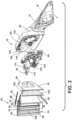
FIGS. 1-11 ,reference numeral 10 generally designates an exterior mirror assembly for avehicle 14 that includes a support feature, such as anarm 18 that has aproximal end 22 coupled with avehicle door 26 and adistal end 30. Amirror assembly 34 is coupled to thearm 18. Themirror assembly 34 includes an electro-optic element 38. Themirror assembly 34 is rotatable about thedistal end 30 between first andsecond positions imager 50 is disposed proximate thedistal end 30 and configured to capture image data within ablind spot zone 54 of thevehicle 14. - Referring to
FIGS. 1 and2 , theexterior mirror assembly 10 includes ahousing 58 configured to shield and protect the electro-optic element 38. It is contemplated that theexterior mirror assembly 10 may be a standard reflective mirror. Theexterior mirror assembly 10 may also include a circuit board, acarrier plate 62, abracket 64, and abezel 66. Although abezel 66 is shown inFIG. 2 , theexterior mirror assembly 10 may be free of thebezel 66. Theexterior mirror assembly 10 may be held together by a snap-fit connection, an interference-fit connection, mechanical fasteners, and/or adhesives. Thearm 18 extends outwardly from thevehicle door 26 as thehousing 58 may be operably coupled with thedistal end 30 of thearm 18. Thevehicle 14 may be a sedan, a sport utility vehicle, a van, a truck, a crossover, or anotherstyle vehicle 14. Additionally, thevehicle 14 may be utilized for personal and/or commercial purposes. - According to various aspects, the electro-
optic element 38 may be made of glass or any other material and/or material combinations configured for use in external mirror applications. The electro-optic element 38 can have any contour, including flat, aspheric, or convex, depending on the selected type of reflection. Additionally or alternatively, the electro-optic element 38 can be an electrochromic mirror having first andsecond substrates 74, 78 with an electro-optic material disposed therebetween. It is contemplated that afront surface 82 or arear surface 86 of thesecond substrate 78 may include a reflective layer configured to display a reflection through the electro-optic material and the first substrate 74. Additionally or alternatively, a front surface or a rear surface of the first substrate 74 may include the reflective layer. In this way, the electro-optic element 38 defines a reflecting surface that provides a user with a rearview of thevehicle 14. A seal 90 extends around the periphery of the first andsecond substrates 74, 78 thereby sealing an electro-optic material between the first andsecond substrates 74, 78. An electrical connector, such as a j-clip orbus bar 94 is disposed proximate top and bottom edges of the first andsecond substrates 74, 78 to selectively apply a voltage to the electro-optic material. Selective application of voltage or reduction of voltage results in darkening and lightening of the electro-optic material between the first substrate 74 and thesecond substrate 78 resulting in the appearance of a dimming mirror. - A border of the
mirror assembly 34 may incorporate a peripheral concealing layer or edge treatment, such as a chrome ring or other similar finish, to conceal a peripheral area of elements located behind the first substrate 74 in themirror assembly 34, including without limitation a seal on an electro-optic element 38, an applique, foam adhesive, or pad printing. For example, the peripheral concealing layer may be advantageous for concealing thebus bar 94 disposed proximate top and bottom edges of the first andsecond substrates 74, 78. - Referring again to
FIG. 2 , theexterior mirror assembly 10 may includeelectronic components 98 and aheater 102, which can extend across a portion, or substantially all, of therear surface 86 of thesecond substrate 78. Theheater 102 includes aconductive track 106 that is illustrated in a serpentine configuration across therear surface 86 of thesecond substrate 78. Aheat conductor 110 may be in communication with theconductive track 106. Theelectronic components 98 may enable theheat conductor 110, which may be advantageous for removing moisture, such as snow or fog from the electro-optic element 38. Theheat conductor 110 operates to heat the electro-optic element 38, which can result in increased performance of the electro-optic element 38. - The
carrier plate 62 supports the electro-optic element 38 and may be formed of molded plastic. Thecarrier plate 62 may be disposed between theheater 102 and thehousing 58. In various examples,electronic components 98, such as a printed circuit board, may be arranged on thecarrier plate 62, such that a mass of theelectronic components 98 is proximate a center of gravity of themirror assembly 34 to minimize vibration of theexterior mirror assembly 10 after installation onto the vehicle 14 (FIG. 1 ). Theelectronic components 98 may be configured as a flexible circuit board or a rigid circuit board, which may have electrical leads printed thereon. As illustrated inFIG. 2 , thecarrier plate 62 covers substantially an entire rear surface of the electro-optic element 38. - In various examples, the
exterior mirror assembly 10 includes thebracket 64, which may extend all the way, or partially, across an inner surface of thehousing 58. In various examples, thebracket 64 defines a space proximate the distal end 30 (FIG. 3 ) to accommodate theimager 50 and asupport bracket 112 that extend from thearm 18 toward themirror assembly 34. To connect the components of theexterior mirror assembly 10, an adhesive liquid, an adhesive tape, or adhesive film, such as double-sided foam adhesive tape, may be provided between thecarrier plate 62 and the and thebracket 64 and attached over thecarrier plate 62. - The
imager 50 may be coupled to thearm 18, such that theimager 50 does not rotate with themirror assembly 34. In various examples, theimager 50 may be at least partially disposed between thehousing 58 and themirror assembly 34. Theimager 50 may be coupled to thesupport bracket 112 and thesupport bracket 112 may be coupled to thearm 18. A power and/ordata line 114 may extend from theimager 50 along and/or through thearm 18 and is operably coupled with a power source and/or a data source of thevehicle 14. Theimager 50 may be a camera or other vision-based device. Theimager 50 may be an area-type imager, such as a charge-coupled device (CCD) or a complementary metal-oxide semiconductor (CMOS) imager. Theimager 50 may be configured to capture image data in a vehicle-rearward direction, vehicle-side direction, or vehicle-forward direction of theexterior mirror assembly 10. Thehousing 58 can protect the electro-optic element 38, theimager 50, and other components of theexterior mirror assembly 10 from the elements and possible damage during regular use. - Referring to
FIGS. 3 and 4 , themirror assembly 34 and thehousing 58 are configured to rotate about thedistal end 30 of thearm 18 between the first andsecond positions FIG. 3 , when in thefirst position 42, a longitudinal extent of themirror assembly 34 is in a substantially horizontal position. When in thefirst position 42, the longitudinal extent of themirror assembly 34 is substantially parallel with thearm 18 and provides a substantially horizontal reflection. - As illustrated in
FIG. 4 , the longitudinal extent of themirror assembly 34 is rotated to be substantially vertical when themirror assembly 34 is in thesecond position 46. In this instance, the longitudinal extent of themirror assembly 34 is generally perpendicular to thearm 18. Additionally or alternatively, when in thesecond position 46, themirror assembly 34 and/or thehousing 58 may extend outwardly from thedistal end 30 of thearm 18. Moreover, themirror assembly 34 provides a greater vertical reflection when in thesecond position 46 as compared to thefirst position 42. Themirror assembly 34 may rotate vertically away from the vehicle door 26 (FIG. 1 ) about a horizontal axis X to thesecond position 46, which can provide for at least a portion of themirror assembly 34 to extend outwardly, beyond thedistal end 30 of thearm 18. - Referring again to
FIGS. 3 and 4 , thearm 18 may define a receivingportion 116 that receives thehousing 58 when thehousing 58 is in thefirst position 42. As thehousing 58 and themirror assembly 34 rotate to thesecond position 46, thehousing 58 rotates out of the receivingportion 116. Accordingly, when thehousing 58 and themirror assembly 34 rotate to thefirst position 42, thehousing 58 abuts a surface defining the receivingportion 116. The receivingportion 116 may provide stability to thehousing 58 when in thefirst position 42. In operation, thehousing 58 and/or themirror assembly 34 rotate about the horizontal axis X. The horizontal axis X extends through thearm 18, thehousing 58, and themirror assembly 34. In this way, the horizontal axis X extends through thearm 18, thehousing 58, and themirror assembly 34 and is generally orthogonal thereto. - Referring to
FIGS. 3 and 4 , thehousing 58 includes afirst edge 118 and asecond edge 120. Thesecond edge 120 is disposed proximate thedistal end 30 of thearm 18 and thefirst edge 118 opposes thesecond edge 120. When theexterior mirror assembly 10 is in thefirst position 42, the first andsecond edges housing 58 are generally horizontally aligned with one another. As theexterior mirror assembly 10 rotates from thefirst position 42 to thesecond position 46, thefirst edge 118 moves to an elevated position and thesecond edge 120 moves to a lowered position. Thesecond edge 120 can remain in contact with thearm 18, while thesecond edge 120 is spaced-apart from thearm 18. When theexterior mirror assembly 10 is in the second position, the first andsecond edges first edge 118 disposed vertically above thesecond edge 120. - Referring to
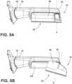
FIGS. 3-5B , when themirror assembly 34 is in thefirst position 42, themirror assembly 34 includes afirst viewing area 122a, asecond viewing area 122b, and athird viewing area 122c. Thefirst viewing area 122a is adjacent to thefirst edge 118 of thehousing 58, thethird viewing area 122c is adjacent to thesecond edge 120 of thehousing 58, and thesecond viewing area 122b is centrally located between the first andthird viewing areas mirror assembly 34 is in thefirst position 42, the mirror assembly provides a greater horizontal reflection, and when themirror assembly 34 is in the second position, 46 the mirror assembly provides a greater vertical reflection. - The horizontal axis X can be oriented at different angles relative to the
arm 18. In a non-limiting example, as illustrated inFIG. 5A , the horizontal axis X may be substantially orthogonal to thearm 18. In such examples, the vertical reflection may generally align with reflection from thethird viewing area 122c and at least a portion of thesecond viewing area 122b of themirror assembly 34. In another non-limiting example, as illustrated inFIG. 5B , the horizontal axis X can extend at an angle relative to thearm 18, such that the horizontal axis X extends through thearm 18 at a first location and through themirror assembly 34 at a second location, where the first location is a greater distance from thevehicle 14 than the second distance. In this way, the horizontal axis X extends at an angle toward thevehicle 14 in a vehicle-forward to a vehicle-rearward direction. The angled horizontal axis X can result in themirror assembly 34 being angled toward the driver when in thesecond position 46. The angledsecond position 46 may capture a vertical reflection that aligns with more of thesecond viewing area 122b. This configuration can allow for a wider reflection from themirror assembly 34 when themirror assembly 34 is in thesecond position 46. - According to various aspects, the
mirror assembly 34 is coupled to thehousing 58. Thehousing 58 includes aperipheral edge 124 that defines an opening 126 (FIG. 2 ), and themirror assembly 34 is coupled to theperipheral edge 124. In non-limiting examples, themirror assembly 34 may be coupled to the entireperipheral edge 124 and fill theopening 126 defined by theperipheral edge 124. In this way, themirror assembly 34 may be a single reflective component disposed within theopening 126 of thehousing 58. The single reflective component may be advantageous for reducing the size of theexterior mirror assembly 10. In such examples, themirror assembly 34 may be free of reflective spotter capabilities. Moreover, the first and/orsecond substrates 74, 78, and accordingly themirror assembly 34, can each be substantially flat and/or planar. Accordingly, themirror assembly 34 includes a generally planar outer surface. - Referring to
FIG. 6 , theimager 50 is coupled to thearm 18 and extends at least partially between thehousing 58 and the mirror assembly 34 (FIG. 2 ). In various examples, thehousing 58 defines anaperture 130 proximate thearm 18 and theimager 50 is disposed within theaperture 130. Theaperture 130 may be sized to accommodate theimager 50 while thehousing 58 rotates around theimager 50 between the first andsecond positions 42, 46 (FIGS. 3 and 4 ) while theimager 50 remains substantially stationary on thearm 18. In this way, theaperture 130 can be any size and/or shape to allow thehousing 58 to rotate with minimal, or no, interference with theimager 50. - As illustrated in
FIG. 6 , apivot member 138 is coupled to thearm 18 and extends through anaperture 142 defined by thecarrier plate 62 and acorresponding aperture 144 defined by thehousing 58. Thepivot member 138 may be coupled to thearm 18 and extend outward in a vehicle-rearward direction therefrom. Thehousing 58 and thecarrier plate 62 may be rotatably coupled to thearm 18 via thepivot member 138. According to various aspects, theimager 50 may be coupled to thearm 18 proximate thepivot member 138 and, accordingly, proximate the horizontal axis X. Thepivot member 138 may be advantageous for providing an electrical connection interface between thevehicle 14 and the various electrical components within theexterior mirror assembly 10. In this way, the power and/ordata line 114 may extend from theimager 50 through thepivot member 138 and at least partially through thearm 18 to connect to the power source and/or data source of the vehicle 14 (FIG. 2 ). - As illustrated in
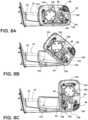
FIGS. 7A-8C , thehousing 58 is configured to rotate and theimager 50 remains stationary on thearm 18.FIGS. 7A-7C illustrate a schematic view of the rotation of thehousing 58 around theimager 50, whileFIGS. 8A-8C illustrate the rotation of thehousing 58 in detail. Theaperture 130 generally defines an arc shape that extends around a portion of thepivot member 138. In a non-limiting example, theaperture 130 generally forms approximately a quarter of a circle or an oblong shape. When thehousing 58 is in thefirst position 42, as illustrated inFIGS. 7A and8A , theimager 50 may be disposed in a first end 132 of theaperture 130. As thehousing 58 rotates between the first andsecond positions FIGS. 7B and8B , thehousing 58 rotates in a manner to move theaperture 130 around theimager 50. - When the
housing 58 is in thesecond position 46, as illustrated inFIGS. 7C and8C , thehousing 58 has shifted such that theimager 50 is disposed in a second end 134 of theaperture 130. Based on the position of thehousing 58, theimager 50 can be disposed in the first end 132 of theaperture 130, the second end 134 of theaperture 130, or at any position therebetween. Theaperture 130 allows thehousing 58 to rotate around thestationary imager 50 without theimager 50 interfering with the rotation of thehousing 58. The arc shape of theaperture 130 may be advantageous for providing space for theimager 50 while thehousing 58 rotates while minimizing the area that air can enter thehousing 58 from a space between thehousing 58 and thearm 18. - The size and shape of the
aperture 130 may minimize an opening or space around theimager 50 to reduce dirt, debris, and other environmental conditions from entering thehousing 58 through theaperture 130. Additionally or alternatively, a cover, membrane, or other protective element may be coupled to thehousing 58 and extend into theaperture 130 to minimize or reduce dirt, debris, and other environmental conditions from entering the interior of theexterior mirror assembly 10. It is contemplated that the protective element may be deformable or adjustable to allow the protective element to move around theimager 50 as thehousing 58 rotates between the first andsecond positions - According to various aspects, electrical connectors from a variety of features within the
exterior mirror assembly 10 may be routed around theaperture 130 through thepivot member 138. The electrical connectors can be coupled to thehousing 58 to clear the space proximate theaperture 130. This configuration may be advantageous to prevent the electrical connectors from impeding the rotation of thehousing 58 and/or interfering with theimager 50. The electrical connectors may be positioned in a manner such that the electrical connectors do not interfere with theimager 50 when thehousing 58 is in thefirst position 42, thesecond position 46, or any position therebetween. - Referring to
FIGS. 2 and7A-8C , due to theaperture 130 in thehousing 58, air can flow from between thehousing 58 and thearm 18 to inside thehousing 58. In this way, theimager 50 may be subject to various weather conditions, such as colder temperatures. Theheater 102 may be operably coupled to theimager 50 to provide heat to theimager 50. Additionally or alternatively, theheater 102 can operate to heat the space within thehousing 58, which may sufficiently warm theimager 50. Theheater 102 may continually provide heat, either directly or indirectly, to theimager 50 when the temperature is at or below a predetermined temperature. A temperature sensor coupled to theexterior mirror assembly 10, or otherwise coupled to the vehicle 14 (FIG. 1 ), may sense the ambient temperature. A controller 162 (FIG. 8 ) may compare the sensed temperature with a predetermined temperature and activate theheater 102 when the sensed temperature is at or below the predetermined temperature. In this way, theheater 102 may warm theimager 50, which can reduce, or prevent, the formation of condensation on the imager that can affect the quality of the captured image data. The use of theheater 102 to warm theimager 50 may reduce the volume of components within theexterior mirror assembly 10. Additionally or alternatively, theexterior mirror assembly 10 may include additional components in thermal communication with theimager 50 to protect theimager 50 from the colder temperatures. - Referring to
FIGS. 2 ,6 , and9 , theimager 50 defines the field ofview 136 that extends through themirror assembly 34 in a vehicle-rearward direction. The field ofview 136 of theimager 50 extends through the front andrear surfaces second substrate 78, through the electro-optic material, and through front and rear surfaces of the first substrate 74. As such, themirror assembly 34 extends through the field ofview 136 and is configured to not substantially interfere with the field ofview 136. It is contemplated that theimager 50 is configured to adjust in response to the dimming or lightening of the electro-optic element 38. - In various examples, the
mirror assembly 34 may include a reflective or transflective coating that provides for the reflective capabilities of themirror assembly 34 while minimizing interference with the field ofview 136 of theimager 50. The reflective coating may be applied to all, or a portion, of themirror assembly 34. In examples where the reflective coating covers a portion of themirror assembly 34, the portion coincides with the field ofview 136 when themirror assembly 34 is in thefirst position 42, thesecond position 46, and any position therebetween. In various examples, the reflective coating can mirror the size and/or shape of theaperture 130. Positioning theimager 50 proximate the horizontal axis X reduces the area of themirror assembly 34 that extends through the field ofview 136, which may be advantageous for improving the accuracy of the field ofview 136 and the captured image data. - Additionally or alternatively, the
mirror assembly 34 may also include a masking layer made of a thin material, which has a black matte material covering a portion of themirror assembly 34. The masking layer may reduce visibility through themirror assembly 34 to components located within thehousing 58. The masking layer may be made with any light-absorbing material, such as black paint, black tape, black foam backing, black ink, or the like. The portion of themirror assembly 34 that is in the field ofview 136 of theimager 50 when themirror assembly 34 is in thefirst position 42, in thesecond position 46, or any position between the first andsecond positions view 136 of theimager 50 or the image data obtained by theimager 50 in the field ofview 136. - Referring to
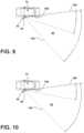
FIG. 9 , themirror assembly 34 provides a reflected image to a driver. The reflected image corresponds with a field ofview 146 of themirror assembly 34, which encompasses an area α adjacent to and behind thevehicle 14. The area α can include aside 150 of thevehicle 14. Theblind spot zone 54 is defined outwardly of the field ofview 146. The field ofview 136 of theimager 50 at least partially overlaps the field ofview 146 of themirror assembly 34. Theimager 50 includes the field ofview 136, which encompasses an area β that completely, or at least partially, encompasses theblind spot zone 54 of thevehicle 14 and/or the field ofview 146. The field ofview 136 of theimager 50 extends outwardly from the field ofview 146 of themirror assembly 34, and away from thevehicle 14. When an object is in theblind spot zone 54, the object may not be visible to the driver on the reflective surface of the mirror assembly 34 (e.g., within the field of view 146), but the object may be in the field ofview 136 of theimager 50. Theimager 50 can capture image data of the object within theblind spot zone 54. It is contemplated that the field ofview 146 of themirror assembly 34 and the field ofview 136 of theimager 50 may extend indefinitely. - Referring to
FIGS. 9 and 10 , themirror assembly 34 defines the field ofview 146 when themirror assembly 34 is in thefirst position 42 andsecond position 46. The field ofview 146 may differ when themirror assembly 34 is in thesecond position 46 relative to when themirror assembly 34 is in thefirst position 42. The reflected image can have a greater horizontal reflection when themirror assembly 34 is in thefirst position 42 and a greater vertical reflection when in thesecond position 46. The field ofview 146 may also differ based on the angle of reflection visible to the driver when themirror assembly 34 is in different positions relative to thevehicle 14. - Referring again to
FIGS. 3, 4 ,9, and 10 , the field ofview 136 of theimager 50 remains constant (e.g., is generally the same) when themirror assembly 34 is in thefirst position 42, as illustrated inFIG. 9 , and when themirror assembly 34 is in thesecond position 46, as illustrated inFIG. 10 . When in thefirst position 42, thesecond position 46, and any position therebetween, the field ofview 136 of theimager 50 at least partially, or completely, overlaps theblind spot zone 54 of thevehicle 14. The field ofview 136 remains substantially constant as thehousing 58 and themirror assembly 34 rotate around theimager 50 between the first andsecond positions imager 50 may continually capture the image data in theblind spot zone 54 without substantial interference from the rotation of themirror assembly 34. - Referring to
FIG. 11 , in various examples, thevehicle 14 may include amonitoring system 158. Themonitoring system 158 may be advantageous for providing and/or displaying the captured image data from theimager 50 to the driver and/or an occupant of thevehicle 14. Thevehicle 14 includes acontroller 162 that has aprocessor 166, amemory 170, and other control circuitry. Instructions orroutines 174 are stored within thememory 170 and executable by theprocessor 166. Thecontroller 162 may be a primary vehicle control (e.g., an electronic control unit), or alternatively, may be a designatedcontroller 162 for themonitoring system 158. Thecontroller 162 may be in communication with various devices that may be incorporated within thevehicle 14 via a communication bus or any other suitable communication interface. Thecontroller 162 may correspond to one or more processors or circuits, which may be configured to process the captured image data received from theimager 50. In this way, the captured image data is communicated from theimager 50 to thecontroller 162 and thecontroller 162 processes the captured image data with one or more algorithms (e.g., routines 174). - The
controller 162 may further be in communication with adisplay assembly 178 of thevehicle 14. Thedisplay assembly 178 may be coupled to thevehicle 14 and viewable by the driver. Thecontroller 162 is configured to display the captured image data received from theimager 50, such that the driver can view the captured image data and, accordingly, view the object with the blind spot zone 54 (FIGS. 9 and 10 ). Additionally or alternatively, thecontroller 162 is configured to receive the captured image data from theimager 50 and convert the captured image data to pixels for display on thedisplay assembly 178. Thedisplay assembly 178 may be configured as, or incorporated in, a center stack display, a rearviewmirror display assembly 178, an external mirror assembly, a removable display, or another display unit within avehicle 14. In a non-limiting example, the firstviewable area 122a can be selectively operated as thedisplay assembly 178 to display the captured image data to the driver. - According to various aspects, the captured image data is communicated to the
display assembly 178, which allows the driver of thevehicle 14 to view the captured image data while thevehicle 14 is operating. In this way, theimager 50 allows the driver to view theblind spot zone 54 of thevehicle 14. Stated differently, the driver of thevehicle 14 can view the field ofview 146 through the reflective surface of themirror assembly 34, as well as, theblind spot zone 54 within the field ofview 136 captured by theimager 50 and displayed on thedisplay assembly 178. - It is generally contemplated that the
imager 50 may be selectively activated and deactivated by one of the occupants within thevehicle 14. The activation and deactivation may be selected by the occupant through a manual, verbal, or gesture command inside thevehicle 14 through a user interface. When activated, the captured image data may be sent from theimager 50 to thecontroller 162, which may then convert the captured image data to pixels for display on thedisplay assembly 178. When deactivated, theimager 50 does not capture image data within theblind spot zone 54 to be displayed to the driver on thedisplay assembly 178. - The
controller 162 is also in communication with themirror assembly 34. Thecontroller 162 is configured to operate the electro-optic element 38 of themirror assembly 34. In various examples, the electro-optic element 38 is configured to darken in response to a signal from thecontroller 162. Thecontroller 162 may receive a signal from a user interface or from various sensors within thevehicle 14 to activate and darken the electro-optic element 38. Additionally or alternatively, thecontroller 162 may receive a signal from the user interface or from the various sensors to deactivate the electro-optic element 38 and thereby lighten the electro-optic element 38. The position of the mirror assembly 34 (e.g., thefirst position 42 or the second position 46) may correspond with a signal to thecontroller 162 to darken and/or lighten the electro-optic element 38. - According to various aspects, the
imager 50 may be automatically and/or manually adjusted to adjust the field ofview 136 and the corresponding captured image data. The driver, or another occupant of thevehicle 14, may input a signal to thecontroller 162 via the user interface to adjust the field ofview 136. The adjustment of the field ofview 136 may include, for example, a position of the field ofview 136 relative to thevehicle 14, a size of the field ofview 136, clarity of the captured image data, combinations thereof, and/or other aspects of theimager 50. Theimager 50 may include one or more lenses to focus theimager 50 and increase the clarity of the captured image data. Additionally or alternatively, theimager 50 may include the one or more lenses which may allow for adjustment of the size and/or direction of the field ofview 136. The adjustment of the field ofview 136 may be accomplished manually by an input from the driver or occupant of thevehicle 14 in response to the images on thedisplay assembly 178. Additionally or alternatively, thecontroller 162 may at least partially process the captured image data from theimager 50 and determine which adjustments can be implemented to increase the quality and/or clarity displayed images. In this way, thecontroller 162 can automatically adjust the field ofview 136 to improve the accuracy of the captured image data within theblind spot zone 54. - Referring to
FIGS. 1-11 , in operation, themirror assembly 34 and thehousing 58 rotate around theimager 50 between the first andsecond positions exterior mirror assembly 10 may include a spring and detent assembly to retain themirror assembly 34 in the first andsecond positions mirror assembly 34 can be manual or automatic. In manual examples, a user can rotate themirror assembly 34 and lock themirror assembly 34 into a selected position. In automatic examples, the rotation of themirror assembly 34 may be accomplished through a motorized assembly, such that the driver of thevehicle 14 can adjust the position of themirror assembly 34 from within thevehicle 14. The reflective surface of themirror assembly 34 provides the field ofview 146 to the driver of thevehicle 14, leaving theblind spot zone 54 outside the field ofview 146. The field ofview 136 of theimager 50 provides captured image data of theblind spot zone 54 to be displayed on thedisplay assembly 178. The field ofview 136 of theimager 50 is substantially constant, whether themirror assembly 34 is in thefirst position 42, thesecond position 46, or any position therebetween. Stated differently, the field ofview 146 of themirror assembly 34 changes as theexterior mirror assembly 10 rotates, but the field ofview 136 of theimager 50 does not change. The consistency of the field ofview 136 of theimager 50 provides continual and consistent images to thedisplay assembly 178 of theblind spot zone 54. - Use of the present device may provide for a variety of advantages. For example, the
mirror assembly 34 may rotate between thefirst position 42 and thesecond position 46 to provide different field ofviews 146 of themirror assembly 34 to the driver of thevehicle 14. Additionally, theimager 50 may at least partially, or completely, overlap with theblind spot zone 54 of thevehicle 14 and is configured to capture image data within theblind spot zone 54. Moreover, the captured image data from the field ofview 136 of theimager 50, including images from theblind spot zone 54, may be communicated to thedisplay assembly 178 for display to the driver of thevehicle 14. Further, the field ofview 136 of theimager 50 remains substantially constant, which may provide consistent imaging to the driver of the object within theblind spot zone 54 of thevehicle 14. Additional benefits or advantages of using this device may also be realized and/or achieved. - It will be understood by one having ordinary skill in the art that construction of the described disclosure and other components is not limited to any specific material. Other exemplary embodiments of the disclosure disclosed herein may be formed from a wide variety of materials, unless described otherwise herein.
- For purposes of this disclosure, the term "coupled" (in all of its forms, couple, coupling, coupled, etc.) generally means the joining of two components (electrical or mechanical) directly or indirectly to one another. Such joining may be stationary in nature or movable in nature. Such joining may be achieved with the two components (electrical or mechanical) and any additional intermediate members being integrally formed as a single unitary body with one another or with the two components. Such joining may be permanent in nature or may be removable or releasable in nature unless otherwise stated.
- It is also important to note that the construction and arrangement of the elements of the disclosure, as shown in the exemplary embodiments, is illustrative only. Although only a few embodiments of the present innovations have been described in detail in this disclosure, those skilled in the art who review this disclosure will readily appreciate that many modifications are possible (e.g., variations in sizes, dimensions, structures, shapes and proportions of the various elements, values of parameters, mounting arrangements, use of materials, colors, orientations, etc.). For example, elements shown as integrally formed may be constructed of multiple parts, or elements shown as multiple parts may be integrally formed, the operation of the interfaces may be reversed or otherwise varied, the length or width of the structures and/or members or connector or other elements of the system may be varied, the nature or number of adjustment positions provided between the elements may be varied. It should be noted that the elements and/or assemblies of the system may be constructed from any of a wide variety of materials that provide sufficient strength or durability, in any of a wide variety of colors, textures, and combinations. Other substitutions, modifications, changes, and omissions may be made in the design, operating conditions, and arrangement of the desired and other exemplary embodiments.
- According to another aspect, a display assembly operably coupled with the mirror assembly, wherein a portion of the mirror assembly displays the image data captured by the imager.
- According to another aspect, a field of view of the imager remains constant as the mirror assembly rotates between the first and second positions.
- According to another aspect, the mirror assembly rotates about a horizontal axis. The horizontal axis is orthogonal to the support feature.
- According to another aspect, the mirror assembly rotates about a horizontal axis that extends at an angle relative to the support feature. The horizontal axis extends through the support feature at a first location and through the mirror assembly at a second location. The first location a different distance from the second end than the second location.
- It will be understood by one having ordinary skill in the art that construction of the described disclosure and other components is not limited to any specific material. Other exemplary embodiments of the disclosure disclosed herein may be formed from a wide variety of materials, unless described otherwise herein.
- For purposes of this disclosure, the term "coupled" (in all of its forms, couple, coupling, coupled, etc.) generally means the joining of two components (electrical or mechanical) directly or indirectly to one another. Such joining may be stationary in nature or movable in nature. Such joining may be achieved with the two components (electrical or mechanical) and any additional intermediate members being integrally formed as a single unitary body with one another or with the two components. Such joining may be permanent in nature or may be removable or releasable in nature unless otherwise stated.
- It is also important to note that the construction and arrangement of the elements of the disclosure, as shown in the exemplary embodiments, is illustrative only. Although only a few embodiments of the present innovations have been described in detail in this disclosure, those skilled in the art who review this disclosure will readily appreciate that many modifications are possible (e.g., variations in sizes, dimensions, structures, shapes and proportions of the various elements, values of parameters, mounting arrangements, use of materials, colors, orientations, etc.) without materially departing from the novel teachings and advantages of the subject matter recited. For example, elements shown as integrally formed may be constructed of multiple parts, or elements shown as multiple parts may be integrally formed, the operation of the interfaces may be reversed or otherwise varied, the length or width of the structures and/or members or connector or other elements of the system may be varied, the nature or number of adjustment positions provided between the elements may be varied. It should be noted that the elements and/or assemblies of the system may be constructed from any of a wide variety of materials that provide sufficient strength or durability, in any of a wide variety of colors, textures, and combinations. Accordingly, all such modifications are intended to be included within the scope of the present innovations. Other substitutions, modifications, changes, and omissions may be made in the design, operating conditions, and arrangement of the desired and other exemplary embodiments without departing from the spirit of the present innovations.
- It will be understood that any described processes or steps within described processes may be combined with other disclosed processes or steps to form structures within the scope of the present disclosure. The exemplary structures and processes disclosed herein are for illustrative purposes and are not to be construed as limiting.
Claims (4)
- A monitoring system (158) for a vehicle (14), comprising:a housing (58) rotatable relative to said vehicle (14) between a horizontal position and a vertical position;a mirror assembly (34) coupled to the housing (58), wherein the mirror assembly (34) includes a rearview mirror having a reflective field of view, and wherein the reflective field of view when the housing (58) is in the horizontal position is different than the reflective field of view when the housing (58) is in the vertical position;an imager (50) disposed between the housing (58) and the mirror assembly (34), wherein the imager (50) captures image data within a field of view, wherein the field of view of the imager (50) is the same when the housing (58) is in the horizontal position and the vertical position, wherein the housing (58) defines an arced aperture, wherein the imager (50) is disposed within the arced aperture, and wherein a position of the imager (50) within the arced aperture changes based on a position of the housing (58);a controller (162) communicatively coupled to the imager (50), wherein the controller (162) receives captured image data from the imager (50); anda display assembly (178) communicatively coupled to the controller (162), wherein the controller (162) converts the image data for display on the display assembly (178).
- The monitoring system of claim 1, wherein the reflective field of view encompasses a first area adjacent to said vehicle (14), and the field of view of the imager (50) encompasses a second area that extends outwardly from the first area relative to a side of said vehicle (14).
- The monitoring system of any of claims 1-2, further comprising:a temperature sensor coupled to the housing (58); anda heater operably coupled to at least one of the mirror assembly (34) and the housing (58), wherein the controller (162) activates the heater in response to a sensed temperature received from the temperature sensor.
- The monitoring system of any of claims 1-3, wherein the housing (58) defines an opening and the mirror assembly (34) fills the opening, and wherein the mirror assembly (34) includes a planar outer surface.
Applications Claiming Priority (2)
| Application Number | Priority Date | Filing Date | Title |
|---|---|---|---|
| US201962928578P | 2019-10-31 | 2019-10-31 | |
| PCT/IB2020/060242WO2021084511A1 (en) | 2019-10-31 | 2020-10-30 | Rotatable outside mirror with imager assembly |
Publications (3)
| Publication Number | Publication Date |
|---|---|
| EP4051539A1 EP4051539A1 (en) | 2022-09-07 |
| EP4051539A4 EP4051539A4 (en) | 2022-12-21 |
| EP4051539B1true EP4051539B1 (en) | 2023-10-18 |
Family
ID=75686877
Family Applications (1)
| Application Number | Title | Priority Date | Filing Date |
|---|---|---|---|
| EP20882619.8AActiveEP4051539B1 (en) | 2019-10-31 | 2020-10-30 | Rotatable outside mirror with imager assembly |
Country Status (4)
| Country | Link |
|---|---|
| US (1) | US11338735B2 (en) |
| EP (1) | EP4051539B1 (en) |
| CN (1) | CN114555421B (en) |
| WO (1) | WO2021084511A1 (en) |
Families Citing this family (3)
| Publication number | Priority date | Publication date | Assignee | Title |
|---|---|---|---|---|
| US10836353B2 (en)* | 2018-11-15 | 2020-11-17 | Fotonation Limited | Vehicle side view camera system with adjustable field of view |
| EP4081423A1 (en)* | 2020-12-23 | 2022-11-02 | Stoneridge Electronics, AB | Camera mirror system with outside air temperature sensor |
| US12292510B2 (en)* | 2022-10-14 | 2025-05-06 | Here Global B.V. | Vehicle mirror assembly with a movable sensor |
Family Cites Families (70)
| Publication number | Priority date | Publication date | Assignee | Title |
|---|---|---|---|---|
| JP2920653B2 (en) | 1990-03-15 | 1999-07-19 | アイシン精機株式会社 | In-vehicle imaging device |
| US5504478A (en) | 1994-01-12 | 1996-04-02 | Gentex Corporation | Radio frequency control system |
| US6631316B2 (en) | 2001-03-05 | 2003-10-07 | Gentex Corporation | Image processing system to control vehicle headlamps or other vehicle equipment |
| US6820987B1 (en)* | 1997-04-11 | 2004-11-23 | Jimmie L. Lewis | Extendable rearview mirror |
| NL1005817C2 (en) | 1997-04-15 | 1998-10-19 | Iku Holding Montfoort Bv | Interior mirror for a vehicle, and actuator for an interior mirror. |
| US6172613B1 (en) | 1998-02-18 | 2001-01-09 | Donnelly Corporation | Rearview mirror assembly incorporating vehicle information display |
| US6326613B1 (en) | 1998-01-07 | 2001-12-04 | Donnelly Corporation | Vehicle interior mirror assembly adapted for containing a rain sensor |
| US6087953A (en) | 1998-02-18 | 2000-07-11 | Donnelly Corporation | Rearview mirror support incorporating vehicle information display |
| EP1044116A2 (en) | 1997-12-31 | 2000-10-18 | Gentex Corporation | Vehicle vision system |
| US6008486A (en) | 1997-12-31 | 1999-12-28 | Gentex Corporation | Wide dynamic range optical sensor |
| US6445287B1 (en) | 2000-02-28 | 2002-09-03 | Donnelly Corporation | Tire inflation assistance monitoring system |
| US6130448A (en) | 1998-08-21 | 2000-10-10 | Gentex Corporation | Optical sensor package and method of making same |
| CA2290182A1 (en) | 1999-01-22 | 2000-07-22 | Lang-Mekra North America, Llc | Rearview mirror, with camera |
| US5971553A (en) | 1999-02-16 | 1999-10-26 | Gentex Corporation | Mirror housing with electrical connector |
| US6023229A (en) | 1999-03-02 | 2000-02-08 | Gentex Corp | Rearview mirror with internally-mounted compass sensor |
| US7064882B2 (en) | 2002-09-30 | 2006-06-20 | Gentex Corporation | Electrochromic devices having no positional offset between substrates |
| US7324261B2 (en) | 1999-07-09 | 2008-01-29 | Gentex Corporation | Electrochromic devices with thin bezel-covered edge |
| AU2001243285A1 (en) | 2000-03-02 | 2001-09-12 | Donnelly Corporation | Video mirror systems incorporating an accessory module |
| US6420800B1 (en) | 2000-05-25 | 2002-07-16 | Gentex Corporation | Rearview mirror with buttons incorporating display |
| US6963437B2 (en) | 2000-10-03 | 2005-11-08 | Gentex Corporation | Devices incorporating electrochromic elements and optical sensors |
| US7543946B2 (en) | 2002-01-10 | 2009-06-09 | Gentex Corporation | Dimmable rearview assembly having a glare sensor |
| US7683326B2 (en) | 2002-07-09 | 2010-03-23 | Gentex Corporation | Vehicle vision system with high dynamic range |
| US7477439B2 (en) | 2002-09-30 | 2009-01-13 | Gentex Corporation | Vehicular rear view mirror elements and assemblies incorporating these elements |
| US8169684B2 (en) | 2002-09-30 | 2012-05-01 | Gentex Corporation | Vehicular rearview mirror elements and assemblies incorporating these elements |
| US7372611B2 (en) | 2002-09-30 | 2008-05-13 | Gentex Corporation | Vehicular rearview mirror elements and assemblies incorporating these elements |
| US8004741B2 (en) | 2004-02-27 | 2011-08-23 | Gentex Corporation | Vehicular rearview mirror elements and assemblies incorporating these elements |
| US7452113B2 (en) | 2004-03-09 | 2008-11-18 | Gentex Corporation | Optics for controlling the direction of light rays and assemblies incorporating the optics |
| US7293901B2 (en) | 2004-03-09 | 2007-11-13 | Gentex Corporation | Optics for controlling the direction of light rays and assemblies incorporating the optics |
| US7526103B2 (en) | 2004-04-15 | 2009-04-28 | Donnelly Corporation | Imaging system for vehicle |
| US7350931B1 (en) | 2004-06-30 | 2008-04-01 | Magna Donnelly Mirrors North America Llc | Vehicular pivot mirror |
| US7306355B2 (en) | 2004-07-13 | 2007-12-11 | Gentex Corporation | Optics for controlling the direction of light rays and assemblies incorporating the optics |
| US7517099B2 (en)* | 2004-09-10 | 2009-04-14 | Arthur Andre Hannah | Automotive blind spot safety system and method |
| JP4838261B2 (en) | 2004-11-18 | 2011-12-14 | ジェンテックス コーポレイション | Image collection and processing system for vehicle equipment control |
| US7417221B2 (en) | 2005-09-08 | 2008-08-26 | Gentex Corporation | Automotive vehicle image sensor |
| US20070183068A1 (en) | 2006-02-03 | 2007-08-09 | Kozlowski Paul J | Power adjust rear view mirror |
| US7423821B2 (en) | 2006-03-24 | 2008-09-09 | Gentex Corporation | Vision system |
| DE102006056069A1 (en)* | 2006-11-20 | 2008-05-21 | Schefenacker Vision Systems Germany Gmbh | Exterior rearview mirror for vehicles, preferably for motor vehicles |
| US7748856B2 (en) | 2007-05-23 | 2010-07-06 | Donnelly Corporation | Exterior mirror element with integral wide angle portion |
| US8786704B2 (en)* | 2007-08-09 | 2014-07-22 | Donnelly Corporation | Vehicle mirror assembly with wide angle element |
| US8587706B2 (en) | 2008-01-30 | 2013-11-19 | Gentex Corporation | Imaging device |
| US8144223B2 (en) | 2009-01-28 | 2012-03-27 | Gentex Corporation | Imaging device |
| US8378284B2 (en) | 2009-01-28 | 2013-02-19 | Gentex Corporation | Imaging device |
| US8004425B2 (en) | 2009-09-30 | 2011-08-23 | Gentex Corporation | Blind spot detection system and method using preexisting vehicular imaging devices |
| US8836888B2 (en) | 2009-12-15 | 2014-09-16 | Gentex Corporation | Modular light source/electronics and automotive rearview assemblies using the same |
| US9969334B2 (en)* | 2010-02-10 | 2018-05-15 | Magna Mirrors Of America, Inc. | Exterior rearview mirror assembly |
| GB2480473A (en)* | 2010-05-20 | 2011-11-23 | Ford Global Tech Llc | A rear view mirror assembly positionable in two different operational orientations |
| US9487159B2 (en) | 2011-08-02 | 2016-11-08 | Magna Electronics Inc. | Vehicle vision system with camera module mounting bracket |
| US9815410B2 (en)* | 2012-08-29 | 2017-11-14 | Smr Patents S.A.R.L. | Side mirror assembly with stationary camera and telescoping mirror head |
| US9767695B2 (en)* | 2012-07-11 | 2017-09-19 | Gentex Corporation | Stand alone blind spot detection system |
| US9139135B2 (en)* | 2012-09-07 | 2015-09-22 | Musaid A. ASSAF | System and method that minimizes hazards of blind spots while driving |
| US9199574B2 (en) | 2012-09-11 | 2015-12-01 | Gentex Corporation | System and method for detecting a blocked imager |
| JP2014069699A (en)* | 2012-09-28 | 2014-04-21 | Aisin Seiki Co Ltd | Side mirror for vehicle and control method thereof |
| US9676336B2 (en)* | 2013-06-25 | 2017-06-13 | Magna Mirrors Of America, Inc. | Exterior rearview mirror assembly for vehicle |
| KR20160075202A (en)* | 2014-12-19 | 2016-06-29 | (주)엘이디스튜디오 | Side mirror module for removing a blind spot of a vehicle |
| US9449390B1 (en)* | 2015-05-19 | 2016-09-20 | Ford Global Technologies, Llc | Detecting an extended side view mirror |
| WO2017160834A1 (en) | 2016-03-16 | 2017-09-21 | Gentex Corporation | Imager module for vehicle |
| JP6768825B2 (en) | 2016-03-16 | 2020-10-14 | ジェンテックス コーポレイション | Camera assembly with occluded image sensor circuit |
| CN109070802B (en) | 2016-05-20 | 2021-09-28 | 金泰克斯公司 | Imager with active exposure correction |
| EP3516631B1 (en) | 2016-09-23 | 2023-06-21 | Gentex Corporation | Imager with wire harness connecting features |
| CN110177712A (en)* | 2016-12-01 | 2019-08-27 | S·R·迈尔斯 | Car mirror |
| EP3554892B1 (en)* | 2016-12-16 | 2021-01-27 | Gentex Corporation | Fold-in outside display mirror |
| US10730436B2 (en) | 2016-12-30 | 2020-08-04 | Gentex Corporation | Vehicular outside rearview assembly |
| US20180197417A1 (en) | 2017-01-11 | 2018-07-12 | Continental Automotive Systems, Inc. | Trailer mode blind spot sensor |
| CN206926584U (en)* | 2017-06-28 | 2018-01-26 | 北京新能源汽车股份有限公司 | Automobile rearview mirror structure and automobile |
| JP7024242B2 (en)* | 2017-08-02 | 2022-02-24 | 市光工業株式会社 | Peripheral visibility device for electrically retractable vehicles |
| US11148596B2 (en)* | 2017-08-23 | 2021-10-19 | Magna Mirrors Of America, Inc. | Exterior rearview mirror assembly |
| JP6939368B2 (en)* | 2017-10-04 | 2021-09-22 | トヨタ自動車株式会社 | Image display device |
| DE102018202387B3 (en)* | 2018-02-16 | 2019-05-02 | Audi Ag | Rearview mirror assembly |
| CN109466453A (en)* | 2018-10-08 | 2019-03-15 | 信利光电股份有限公司 | A kind of vehicle rearview system and method |
| US10836353B2 (en)* | 2018-11-15 | 2020-11-17 | Fotonation Limited | Vehicle side view camera system with adjustable field of view |
- 2020
- 2020-10-30EPEP20882619.8Apatent/EP4051539B1/enactiveActive
- 2020-10-30USUS17/084,737patent/US11338735B2/enactiveActive
- 2020-10-30WOPCT/IB2020/060242patent/WO2021084511A1/ennot_activeCeased
- 2020-10-30CNCN202080070693.5Apatent/CN114555421B/enactiveActive
Also Published As
| Publication number | Publication date |
|---|---|
| CN114555421B (en) | 2024-03-26 |
| CN114555421A (en) | 2022-05-27 |
| EP4051539A4 (en) | 2022-12-21 |
| US20210129753A1 (en) | 2021-05-06 |
| WO2021084511A1 (en) | 2021-05-06 |
| EP4051539A1 (en) | 2022-09-07 |
| US11338735B2 (en) | 2022-05-24 |
Similar Documents
| Publication | Publication Date | Title |
|---|---|---|
| EP4051539B1 (en) | Rotatable outside mirror with imager assembly | |
| US12214727B2 (en) | Vehicular exterior rearview mirror assembly with extendable and retractable mirror head | |
| US11794648B2 (en) | Exterior rearview mirror assembly | |
| US10099618B2 (en) | Exterior rearview mirror assembly | |
| US20170355312A1 (en) | Interior rearview mirror assembly with full screen video display | |
| US9827913B2 (en) | Exterior rearview mirror assembly | |
| EP2817172B1 (en) | Exterior rearview mirror assembly | |
| US11325535B2 (en) | Exterior rearview mirror assembly | |
| EP3554892B1 (en) | Fold-in outside display mirror | |
| CN108367712B (en) | Bimodal mechanism with optical switch | |
| US12351108B2 (en) | Vehicular exterior rearview mirror assembly with extendable and retractable mirror head | |
| US20250026267A1 (en) | Vehicular exterior rearview mirror system | |
| EP3935830A1 (en) | Image presentation for rear view mirror systems with cameras | |
| US20220258669A1 (en) | Vehicular exterior rearview mirror assembly |
Legal Events
| Date | Code | Title | Description |
|---|---|---|---|
| STAA | Information on the status of an ep patent application or granted ep patent | Free format text:STATUS: THE INTERNATIONAL PUBLICATION HAS BEEN MADE | |
| PUAI | Public reference made under article 153(3) epc to a published international application that has entered the european phase | Free format text:ORIGINAL CODE: 0009012 | |
| STAA | Information on the status of an ep patent application or granted ep patent | Free format text:STATUS: REQUEST FOR EXAMINATION WAS MADE | |
| 17P | Request for examination filed | Effective date:20220512 | |
| AK | Designated contracting states | Kind code of ref document:A1 Designated state(s):AL AT BE BG CH CY CZ DE DK EE ES FI FR GB GR HR HU IE IS IT LI LT LU LV MC MK MT NL NO PL PT RO RS SE SI SK SM TR | |
| A4 | Supplementary search report drawn up and despatched | Effective date:20221122 | |
| RIC1 | Information provided on ipc code assigned before grant | Ipc:H04N 7/18 20060101ALI20221116BHEP Ipc:B60R 1/12 20060101ALI20221116BHEP Ipc:B60R 1/076 20060101ALI20221116BHEP Ipc:B60R 1/07 20060101ALI20221116BHEP Ipc:B60R 1/062 20060101ALI20221116BHEP Ipc:B60R 1/06 20060101AFI20221116BHEP | |
| DAV | Request for validation of the european patent (deleted) | ||
| DAX | Request for extension of the european patent (deleted) | ||
| GRAP | Despatch of communication of intention to grant a patent | Free format text:ORIGINAL CODE: EPIDOSNIGR1 | |
| STAA | Information on the status of an ep patent application or granted ep patent | Free format text:STATUS: GRANT OF PATENT IS INTENDED | |
| P01 | Opt-out of the competence of the unified patent court (upc) registered | Effective date:20230503 | |
| INTG | Intention to grant announced | Effective date:20230613 | |
| GRAS | Grant fee paid | Free format text:ORIGINAL CODE: EPIDOSNIGR3 | |
| GRAA | (expected) grant | Free format text:ORIGINAL CODE: 0009210 | |
| STAA | Information on the status of an ep patent application or granted ep patent | Free format text:STATUS: THE PATENT HAS BEEN GRANTED | |
| AK | Designated contracting states | Kind code of ref document:B1 Designated state(s):AL AT BE BG CH CY CZ DE DK EE ES FI FR GB GR HR HU IE IS IT LI LT LU LV MC MK MT NL NO PL PT RO RS SE SI SK SM TR | |
| REG | Reference to a national code | Ref country code:GB Ref legal event code:FG4D | |
| REG | Reference to a national code | Ref country code:CH Ref legal event code:EP | |
| REG | Reference to a national code | Ref country code:DE Ref legal event code:R096 Ref document number:602020019623 Country of ref document:DE | |
| REG | Reference to a national code | Ref country code:IE Ref legal event code:FG4D | |
| REG | Reference to a national code | Ref country code:LT Ref legal event code:MG9D | |
| REG | Reference to a national code | Ref country code:NL Ref legal event code:MP Effective date:20231018 | |
| REG | Reference to a national code | Ref country code:AT Ref legal event code:MK05 Ref document number:1622169 Country of ref document:AT Kind code of ref document:T Effective date:20231018 | |
| PG25 | Lapsed in a contracting state [announced via postgrant information from national office to epo] | Ref country code:NL Free format text:LAPSE BECAUSE OF FAILURE TO SUBMIT A TRANSLATION OF THE DESCRIPTION OR TO PAY THE FEE WITHIN THE PRESCRIBED TIME-LIMIT Effective date:20231018 | |
| PG25 | Lapsed in a contracting state [announced via postgrant information from national office to epo] | Ref country code:GR Free format text:LAPSE BECAUSE OF FAILURE TO SUBMIT A TRANSLATION OF THE DESCRIPTION OR TO PAY THE FEE WITHIN THE PRESCRIBED TIME-LIMIT Effective date:20240119 | |
| PG25 | Lapsed in a contracting state [announced via postgrant information from national office to epo] | Ref country code:IS Free format text:LAPSE BECAUSE OF FAILURE TO SUBMIT A TRANSLATION OF THE DESCRIPTION OR TO PAY THE FEE WITHIN THE PRESCRIBED TIME-LIMIT Effective date:20240218 | |
| PG25 | Lapsed in a contracting state [announced via postgrant information from national office to epo] | Ref country code:LT Free format text:LAPSE BECAUSE OF FAILURE TO SUBMIT A TRANSLATION OF THE DESCRIPTION OR TO PAY THE FEE WITHIN THE PRESCRIBED TIME-LIMIT Effective date:20231018 | |
| PG25 | Lapsed in a contracting state [announced via postgrant information from national office to epo] | Ref country code:AT Free format text:LAPSE BECAUSE OF FAILURE TO SUBMIT A TRANSLATION OF THE DESCRIPTION OR TO PAY THE FEE WITHIN THE PRESCRIBED TIME-LIMIT Effective date:20231018 | |
| PG25 | Lapsed in a contracting state [announced via postgrant information from national office to epo] | Ref country code:ES Free format text:LAPSE BECAUSE OF FAILURE TO SUBMIT A TRANSLATION OF THE DESCRIPTION OR TO PAY THE FEE WITHIN THE PRESCRIBED TIME-LIMIT Effective date:20231018 | |
| PG25 | Lapsed in a contracting state [announced via postgrant information from national office to epo] | Ref country code:LT Free format text:LAPSE BECAUSE OF FAILURE TO SUBMIT A TRANSLATION OF THE DESCRIPTION OR TO PAY THE FEE WITHIN THE PRESCRIBED TIME-LIMIT Effective date:20231018 Ref country code:IS Free format text:LAPSE BECAUSE OF FAILURE TO SUBMIT A TRANSLATION OF THE DESCRIPTION OR TO PAY THE FEE WITHIN THE PRESCRIBED TIME-LIMIT Effective date:20240218 Ref country code:GR Free format text:LAPSE BECAUSE OF FAILURE TO SUBMIT A TRANSLATION OF THE DESCRIPTION OR TO PAY THE FEE WITHIN THE PRESCRIBED TIME-LIMIT Effective date:20240119 Ref country code:ES Free format text:LAPSE BECAUSE OF FAILURE TO SUBMIT A TRANSLATION OF THE DESCRIPTION OR TO PAY THE FEE WITHIN THE PRESCRIBED TIME-LIMIT Effective date:20231018 Ref country code:BG Free format text:LAPSE BECAUSE OF FAILURE TO SUBMIT A TRANSLATION OF THE DESCRIPTION OR TO PAY THE FEE WITHIN THE PRESCRIBED TIME-LIMIT Effective date:20240118 Ref country code:AT Free format text:LAPSE BECAUSE OF FAILURE TO SUBMIT A TRANSLATION OF THE DESCRIPTION OR TO PAY THE FEE WITHIN THE PRESCRIBED TIME-LIMIT Effective date:20231018 Ref country code:PT Free format text:LAPSE BECAUSE OF FAILURE TO SUBMIT A TRANSLATION OF THE DESCRIPTION OR TO PAY THE FEE WITHIN THE PRESCRIBED TIME-LIMIT Effective date:20240219 | |
| PG25 | Lapsed in a contracting state [announced via postgrant information from national office to epo] | Ref country code:SE Free format text:LAPSE BECAUSE OF FAILURE TO SUBMIT A TRANSLATION OF THE DESCRIPTION OR TO PAY THE FEE WITHIN THE PRESCRIBED TIME-LIMIT Effective date:20231018 Ref country code:RS Free format text:LAPSE BECAUSE OF FAILURE TO SUBMIT A TRANSLATION OF THE DESCRIPTION OR TO PAY THE FEE WITHIN THE PRESCRIBED TIME-LIMIT Effective date:20231018 Ref country code:PL Free format text:LAPSE BECAUSE OF FAILURE TO SUBMIT A TRANSLATION OF THE DESCRIPTION OR TO PAY THE FEE WITHIN THE PRESCRIBED TIME-LIMIT Effective date:20231018 Ref country code:NO Free format text:LAPSE BECAUSE OF FAILURE TO SUBMIT A TRANSLATION OF THE DESCRIPTION OR TO PAY THE FEE WITHIN THE PRESCRIBED TIME-LIMIT Effective date:20240118 Ref country code:LV Free format text:LAPSE BECAUSE OF FAILURE TO SUBMIT A TRANSLATION OF THE DESCRIPTION OR TO PAY THE FEE WITHIN THE PRESCRIBED TIME-LIMIT Effective date:20231018 Ref country code:HR Free format text:LAPSE BECAUSE OF FAILURE TO SUBMIT A TRANSLATION OF THE DESCRIPTION OR TO PAY THE FEE WITHIN THE PRESCRIBED TIME-LIMIT Effective date:20231018 | |
| REG | Reference to a national code | Ref country code:CH Ref legal event code:PL | |
| REG | Reference to a national code | Ref country code:BE Ref legal event code:MM Effective date:20231031 | |
| PG25 | Lapsed in a contracting state [announced via postgrant information from national office to epo] | Ref country code:LU Free format text:LAPSE BECAUSE OF NON-PAYMENT OF DUE FEES Effective date:20231030 | |
| PG25 | Lapsed in a contracting state [announced via postgrant information from national office to epo] | Ref country code:LU Free format text:LAPSE BECAUSE OF NON-PAYMENT OF DUE FEES Effective date:20231030 | |
| PG25 | Lapsed in a contracting state [announced via postgrant information from national office to epo] | Ref country code:DK Free format text:LAPSE BECAUSE OF FAILURE TO SUBMIT A TRANSLATION OF THE DESCRIPTION OR TO PAY THE FEE WITHIN THE PRESCRIBED TIME-LIMIT Effective date:20231018 | |
| PG25 | Lapsed in a contracting state [announced via postgrant information from national office to epo] | Ref country code:CH Free format text:LAPSE BECAUSE OF NON-PAYMENT OF DUE FEES Effective date:20231031 | |
| REG | Reference to a national code | Ref country code:DE Ref legal event code:R097 Ref document number:602020019623 Country of ref document:DE | |
| PG25 | Lapsed in a contracting state [announced via postgrant information from national office to epo] | Ref country code:CZ Free format text:LAPSE BECAUSE OF FAILURE TO SUBMIT A TRANSLATION OF THE DESCRIPTION OR TO PAY THE FEE WITHIN THE PRESCRIBED TIME-LIMIT Effective date:20231018 | |
| PG25 | Lapsed in a contracting state [announced via postgrant information from national office to epo] | Ref country code:SK Free format text:LAPSE BECAUSE OF FAILURE TO SUBMIT A TRANSLATION OF THE DESCRIPTION OR TO PAY THE FEE WITHIN THE PRESCRIBED TIME-LIMIT Effective date:20231018 | |
| PG25 | Lapsed in a contracting state [announced via postgrant information from national office to epo] | Ref country code:SM Free format text:LAPSE BECAUSE OF FAILURE TO SUBMIT A TRANSLATION OF THE DESCRIPTION OR TO PAY THE FEE WITHIN THE PRESCRIBED TIME-LIMIT Effective date:20231018 Ref country code:SK Free format text:LAPSE BECAUSE OF FAILURE TO SUBMIT A TRANSLATION OF THE DESCRIPTION OR TO PAY THE FEE WITHIN THE PRESCRIBED TIME-LIMIT Effective date:20231018 Ref country code:RO Free format text:LAPSE BECAUSE OF FAILURE TO SUBMIT A TRANSLATION OF THE DESCRIPTION OR TO PAY THE FEE WITHIN THE PRESCRIBED TIME-LIMIT Effective date:20231018 Ref country code:IT Free format text:LAPSE BECAUSE OF FAILURE TO SUBMIT A TRANSLATION OF THE DESCRIPTION OR TO PAY THE FEE WITHIN THE PRESCRIBED TIME-LIMIT Effective date:20231018 Ref country code:EE Free format text:LAPSE BECAUSE OF FAILURE TO SUBMIT A TRANSLATION OF THE DESCRIPTION OR TO PAY THE FEE WITHIN THE PRESCRIBED TIME-LIMIT Effective date:20231018 Ref country code:DK Free format text:LAPSE BECAUSE OF FAILURE TO SUBMIT A TRANSLATION OF THE DESCRIPTION OR TO PAY THE FEE WITHIN THE PRESCRIBED TIME-LIMIT Effective date:20231018 Ref country code:CZ Free format text:LAPSE BECAUSE OF FAILURE TO SUBMIT A TRANSLATION OF THE DESCRIPTION OR TO PAY THE FEE WITHIN THE PRESCRIBED TIME-LIMIT Effective date:20231018 Ref country code:CH Free format text:LAPSE BECAUSE OF NON-PAYMENT OF DUE FEES Effective date:20231031 | |
| PLBE | No opposition filed within time limit | Free format text:ORIGINAL CODE: 0009261 | |
| STAA | Information on the status of an ep patent application or granted ep patent | Free format text:STATUS: NO OPPOSITION FILED WITHIN TIME LIMIT | |
| PG25 | Lapsed in a contracting state [announced via postgrant information from national office to epo] | Ref country code:MC Free format text:LAPSE BECAUSE OF FAILURE TO SUBMIT A TRANSLATION OF THE DESCRIPTION OR TO PAY THE FEE WITHIN THE PRESCRIBED TIME-LIMIT Effective date:20231018 | |
| PG25 | Lapsed in a contracting state [announced via postgrant information from national office to epo] | Ref country code:MC Free format text:LAPSE BECAUSE OF FAILURE TO SUBMIT A TRANSLATION OF THE DESCRIPTION OR TO PAY THE FEE WITHIN THE PRESCRIBED TIME-LIMIT Effective date:20231018 Ref country code:BE Free format text:LAPSE BECAUSE OF NON-PAYMENT OF DUE FEES Effective date:20231031 | |
| 26N | No opposition filed | Effective date:20240719 | |
| PG25 | Lapsed in a contracting state [announced via postgrant information from national office to epo] | Ref country code:IE Free format text:LAPSE BECAUSE OF NON-PAYMENT OF DUE FEES Effective date:20231030 | |
| PGFP | Annual fee paid to national office [announced via postgrant information from national office to epo] | Ref country code:GB Payment date:20240919 Year of fee payment:5 | |
| PGFP | Annual fee paid to national office [announced via postgrant information from national office to epo] | Ref country code:FR Payment date:20240919 Year of fee payment:5 | |
| PG25 | Lapsed in a contracting state [announced via postgrant information from national office to epo] | Ref country code:SI Free format text:LAPSE BECAUSE OF FAILURE TO SUBMIT A TRANSLATION OF THE DESCRIPTION OR TO PAY THE FEE WITHIN THE PRESCRIBED TIME-LIMIT Effective date:20231018 | |
| PG25 | Lapsed in a contracting state [announced via postgrant information from national office to epo] | Ref country code:SI Free format text:LAPSE BECAUSE OF FAILURE TO SUBMIT A TRANSLATION OF THE DESCRIPTION OR TO PAY THE FEE WITHIN THE PRESCRIBED TIME-LIMIT Effective date:20231018 Ref country code:IE Free format text:LAPSE BECAUSE OF NON-PAYMENT OF DUE FEES Effective date:20231030 | |
| PGFP | Annual fee paid to national office [announced via postgrant information from national office to epo] | Ref country code:DE Payment date:20240919 Year of fee payment:5 | |
| PG25 | Lapsed in a contracting state [announced via postgrant information from national office to epo] | Ref country code:FI Free format text:LAPSE BECAUSE OF FAILURE TO SUBMIT A TRANSLATION OF THE DESCRIPTION OR TO PAY THE FEE WITHIN THE PRESCRIBED TIME-LIMIT Effective date:20231019 | |
| PG25 | Lapsed in a contracting state [announced via postgrant information from national office to epo] | Ref country code:CY Free format text:LAPSE BECAUSE OF FAILURE TO SUBMIT A TRANSLATION OF THE DESCRIPTION OR TO PAY THE FEE WITHIN THE PRESCRIBED TIME-LIMIT; INVALID AB INITIO Effective date:20201030 | |
| PG25 | Lapsed in a contracting state [announced via postgrant information from national office to epo] | Ref country code:HU Free format text:LAPSE BECAUSE OF FAILURE TO SUBMIT A TRANSLATION OF THE DESCRIPTION OR TO PAY THE FEE WITHIN THE PRESCRIBED TIME-LIMIT; INVALID AB INITIO Effective date:20201030 |