EP4049627A1 - Prosthetic heart valve having improved commissure supports - Google Patents
Prosthetic heart valve having improved commissure supportsDownload PDFInfo
- Publication number
- EP4049627A1 EP4049627A1EP22167528.3AEP22167528AEP4049627A1EP 4049627 A1EP4049627 A1EP 4049627A1EP 22167528 AEP22167528 AEP 22167528AEP 4049627 A1EP4049627 A1EP 4049627A1
- Authority
- EP
- European Patent Office
- Prior art keywords
- frame
- prosthetic valve
- leaflets
- leaflet
- row
- Prior art date
- Legal status (The legal status is an assumption and is not a legal conclusion. Google has not performed a legal analysis and makes no representation as to the accuracy of the status listed.)
- Pending
Links
Images


Classifications
- A—HUMAN NECESSITIES
- A61—MEDICAL OR VETERINARY SCIENCE; HYGIENE
- A61F—FILTERS IMPLANTABLE INTO BLOOD VESSELS; PROSTHESES; DEVICES PROVIDING PATENCY TO, OR PREVENTING COLLAPSING OF, TUBULAR STRUCTURES OF THE BODY, e.g. STENTS; ORTHOPAEDIC, NURSING OR CONTRACEPTIVE DEVICES; FOMENTATION; TREATMENT OR PROTECTION OF EYES OR EARS; BANDAGES, DRESSINGS OR ABSORBENT PADS; FIRST-AID KITS
- A61F2/00—Filters implantable into blood vessels; Prostheses, i.e. artificial substitutes or replacements for parts of the body; Appliances for connecting them with the body; Devices providing patency to, or preventing collapsing of, tubular structures of the body, e.g. stents
- A61F2/02—Prostheses implantable into the body
- A61F2/24—Heart valves ; Vascular valves, e.g. venous valves; Heart implants, e.g. passive devices for improving the function of the native valve or the heart muscle; Transmyocardial revascularisation [TMR] devices; Valves implantable in the body
- A61F2/2409—Support rings therefor, e.g. for connecting valves to tissue
- A—HUMAN NECESSITIES
- A61—MEDICAL OR VETERINARY SCIENCE; HYGIENE
- A61F—FILTERS IMPLANTABLE INTO BLOOD VESSELS; PROSTHESES; DEVICES PROVIDING PATENCY TO, OR PREVENTING COLLAPSING OF, TUBULAR STRUCTURES OF THE BODY, e.g. STENTS; ORTHOPAEDIC, NURSING OR CONTRACEPTIVE DEVICES; FOMENTATION; TREATMENT OR PROTECTION OF EYES OR EARS; BANDAGES, DRESSINGS OR ABSORBENT PADS; FIRST-AID KITS
- A61F2/00—Filters implantable into blood vessels; Prostheses, i.e. artificial substitutes or replacements for parts of the body; Appliances for connecting them with the body; Devices providing patency to, or preventing collapsing of, tubular structures of the body, e.g. stents
- A61F2/02—Prostheses implantable into the body
- A61F2/24—Heart valves ; Vascular valves, e.g. venous valves; Heart implants, e.g. passive devices for improving the function of the native valve or the heart muscle; Transmyocardial revascularisation [TMR] devices; Valves implantable in the body
- A61F2/2412—Heart valves ; Vascular valves, e.g. venous valves; Heart implants, e.g. passive devices for improving the function of the native valve or the heart muscle; Transmyocardial revascularisation [TMR] devices; Valves implantable in the body with soft flexible valve members, e.g. tissue valves shaped like natural valves
- A61F2/2418—Scaffolds therefor, e.g. support stents
- A—HUMAN NECESSITIES
- A61—MEDICAL OR VETERINARY SCIENCE; HYGIENE
- A61F—FILTERS IMPLANTABLE INTO BLOOD VESSELS; PROSTHESES; DEVICES PROVIDING PATENCY TO, OR PREVENTING COLLAPSING OF, TUBULAR STRUCTURES OF THE BODY, e.g. STENTS; ORTHOPAEDIC, NURSING OR CONTRACEPTIVE DEVICES; FOMENTATION; TREATMENT OR PROTECTION OF EYES OR EARS; BANDAGES, DRESSINGS OR ABSORBENT PADS; FIRST-AID KITS
- A61F2/00—Filters implantable into blood vessels; Prostheses, i.e. artificial substitutes or replacements for parts of the body; Appliances for connecting them with the body; Devices providing patency to, or preventing collapsing of, tubular structures of the body, e.g. stents
- A61F2/02—Prostheses implantable into the body
- A61F2/24—Heart valves ; Vascular valves, e.g. venous valves; Heart implants, e.g. passive devices for improving the function of the native valve or the heart muscle; Transmyocardial revascularisation [TMR] devices; Valves implantable in the body
- A61F2/2427—Devices for manipulating or deploying heart valves during implantation
- A61F2/243—Deployment by mechanical expansion
- A61F2/2433—Deployment by mechanical expansion using balloon catheter
- A—HUMAN NECESSITIES
- A61—MEDICAL OR VETERINARY SCIENCE; HYGIENE
- A61F—FILTERS IMPLANTABLE INTO BLOOD VESSELS; PROSTHESES; DEVICES PROVIDING PATENCY TO, OR PREVENTING COLLAPSING OF, TUBULAR STRUCTURES OF THE BODY, e.g. STENTS; ORTHOPAEDIC, NURSING OR CONTRACEPTIVE DEVICES; FOMENTATION; TREATMENT OR PROTECTION OF EYES OR EARS; BANDAGES, DRESSINGS OR ABSORBENT PADS; FIRST-AID KITS
- A61F2220/00—Fixations or connections for prostheses classified in groups A61F2/00 - A61F2/26 or A61F2/82 or A61F9/00 or A61F11/00 or subgroups thereof
- A61F2220/0025—Connections or couplings between prosthetic parts, e.g. between modular parts; Connecting elements
- A61F2220/0075—Connections or couplings between prosthetic parts, e.g. between modular parts; Connecting elements sutured, ligatured or stitched, retained or tied with a rope, string, thread, wire or cable
- A—HUMAN NECESSITIES
- A61—MEDICAL OR VETERINARY SCIENCE; HYGIENE
- A61F—FILTERS IMPLANTABLE INTO BLOOD VESSELS; PROSTHESES; DEVICES PROVIDING PATENCY TO, OR PREVENTING COLLAPSING OF, TUBULAR STRUCTURES OF THE BODY, e.g. STENTS; ORTHOPAEDIC, NURSING OR CONTRACEPTIVE DEVICES; FOMENTATION; TREATMENT OR PROTECTION OF EYES OR EARS; BANDAGES, DRESSINGS OR ABSORBENT PADS; FIRST-AID KITS
- A61F2230/00—Geometry of prostheses classified in groups A61F2/00 - A61F2/26 or A61F2/82 or A61F9/00 or A61F11/00 or subgroups thereof
- A61F2230/0002—Two-dimensional shapes, e.g. cross-sections
- A61F2230/0004—Rounded shapes, e.g. with rounded corners
- A61F2230/0013—Horseshoe-shaped, e.g. crescent-shaped, C-shaped, U-shaped
- A—HUMAN NECESSITIES
- A61—MEDICAL OR VETERINARY SCIENCE; HYGIENE
- A61F—FILTERS IMPLANTABLE INTO BLOOD VESSELS; PROSTHESES; DEVICES PROVIDING PATENCY TO, OR PREVENTING COLLAPSING OF, TUBULAR STRUCTURES OF THE BODY, e.g. STENTS; ORTHOPAEDIC, NURSING OR CONTRACEPTIVE DEVICES; FOMENTATION; TREATMENT OR PROTECTION OF EYES OR EARS; BANDAGES, DRESSINGS OR ABSORBENT PADS; FIRST-AID KITS
- A61F2230/00—Geometry of prostheses classified in groups A61F2/00 - A61F2/26 or A61F2/82 or A61F9/00 or A61F11/00 or subgroups thereof
- A61F2230/0002—Two-dimensional shapes, e.g. cross-sections
- A61F2230/0028—Shapes in the form of latin or greek characters
- A61F2230/0054—V-shaped
- A—HUMAN NECESSITIES
- A61—MEDICAL OR VETERINARY SCIENCE; HYGIENE
- A61F—FILTERS IMPLANTABLE INTO BLOOD VESSELS; PROSTHESES; DEVICES PROVIDING PATENCY TO, OR PREVENTING COLLAPSING OF, TUBULAR STRUCTURES OF THE BODY, e.g. STENTS; ORTHOPAEDIC, NURSING OR CONTRACEPTIVE DEVICES; FOMENTATION; TREATMENT OR PROTECTION OF EYES OR EARS; BANDAGES, DRESSINGS OR ABSORBENT PADS; FIRST-AID KITS
- A61F2250/00—Special features of prostheses classified in groups A61F2/00 - A61F2/26 or A61F2/82 or A61F9/00 or A61F11/00 or subgroups thereof
- A61F2250/0014—Special features of prostheses classified in groups A61F2/00 - A61F2/26 or A61F2/82 or A61F9/00 or A61F11/00 or subgroups thereof having different values of a given property or geometrical feature, e.g. mechanical property or material property, at different locations within the same prosthesis
- A61F2250/0036—Special features of prostheses classified in groups A61F2/00 - A61F2/26 or A61F2/82 or A61F9/00 or A61F11/00 or subgroups thereof having different values of a given property or geometrical feature, e.g. mechanical property or material property, at different locations within the same prosthesis differing in thickness
- A—HUMAN NECESSITIES
- A61—MEDICAL OR VETERINARY SCIENCE; HYGIENE
- A61F—FILTERS IMPLANTABLE INTO BLOOD VESSELS; PROSTHESES; DEVICES PROVIDING PATENCY TO, OR PREVENTING COLLAPSING OF, TUBULAR STRUCTURES OF THE BODY, e.g. STENTS; ORTHOPAEDIC, NURSING OR CONTRACEPTIVE DEVICES; FOMENTATION; TREATMENT OR PROTECTION OF EYES OR EARS; BANDAGES, DRESSINGS OR ABSORBENT PADS; FIRST-AID KITS
- A61F2250/00—Special features of prostheses classified in groups A61F2/00 - A61F2/26 or A61F2/82 or A61F9/00 or A61F11/00 or subgroups thereof
- A61F2250/0014—Special features of prostheses classified in groups A61F2/00 - A61F2/26 or A61F2/82 or A61F9/00 or A61F11/00 or subgroups thereof having different values of a given property or geometrical feature, e.g. mechanical property or material property, at different locations within the same prosthesis
- A61F2250/0039—Special features of prostheses classified in groups A61F2/00 - A61F2/26 or A61F2/82 or A61F9/00 or A61F11/00 or subgroups thereof having different values of a given property or geometrical feature, e.g. mechanical property or material property, at different locations within the same prosthesis differing in diameter
Definitions
- the present disclosureconcerns embodiments of a prosthetic heart valve, and delivery systems for implanting prosthetic heart valves.
- the human heartcan suffer from various valvular diseases. These valvular diseases can result in significant malfunctioning of the heart and ultimately require replacement of the native valve with an artificial valve.
- valvular diseasescan result in significant malfunctioning of the heart and ultimately require replacement of the native valve with an artificial valve.
- Various surgical techniquesmay be used to replace or repair a diseased or damaged native valve. Due to stenosis and other heart valve diseases, thousands of patients undergo surgery each year wherein the defective native heart valve is replaced by a prosthetic valve. Another less drastic method for treating defective valves is through repair or reconstruction, which is typically used on minimally calcified valves. The problem with surgical therapy is the significant risk it imposes on these chronically ill patients with high morbidity and mortality rates associated with surgical repair.
- a prosthetic valveis configured to be implanted in a much less invasive procedure by way of catheterization.
- U.S. Patent Nos. 5,411,522 and 6,730,118which are incorporated herein by reference, describe collapsible transcatheter prosthetic heart valves that can be percutaneously introduced in a compressed state on a catheter and expanded in the desired position by balloon inflation or by utilization of a self-expanding frame or stent.
- An important design parameter of a transcatheter prosthetic heart valveis the diameter of the folded or crimped profile.
- the diameter of the crimped profileis important because it directly influences the physician's ability to advance the transcatheter prosthetic heart valve through the femoral artery or vein. More particularly, a smaller profile allows for treatment of a wider population of patients, with enhanced safety.
- a prosthetic heart valve according to the present disclosurecomprises a radially collapsible and expandable annular frame and a leaflet structure comprising a plurality of leaflets mounted within the frame.
- the framein particular embodiments can have commissure attachment portions that are configured to support the commissures of the leaflets at locations spaced radially inwardly toward the longitudinal flow axis of the prosthetic valve relative to the frame portions circumscribing the moveable portions of the leaflets.
- a prosthetic valvecomprises a radially collapsible and expandable annular frame.
- the framehas a plurality of angularly spaced commissure attachment portions and a plurality of lobed portions extending between the commissure attachment portions.
- the framealso has an inlet end and an outlet end.
- a leaflet structurecomprises a plurality of leaflets, each leaflet comprising opposing side portions and an upper edge extending between the side portions. Each side portion is secured to an adjacent side portion of another leaflet to form commissures of the leaflet structure, each commissure being attached to one of the commissure attachment portions of the frame.
- the leafletsare configured to move between an open position to allow blood to flow through the prosthetic valve from the inlet end to the outlet end and a closed position to inhibit the flow of blood through the prosthetic valve from the outlet end to the inlet end, wherein the upper edges of the leaflets are spaced radially inwardly of the lobed portion of the frame when the leaflets are in the open position.
- a prosthetic valvecomprises a radially collapsible and expandable annular frame.
- the framecomprises an inlet portion and an outlet portion, the outlet portion comprising a plurality of angularly spaced, cantilevered commissure attachment posts extending radially inwardly toward a longitudinal flow axis of the prosthetic valve.
- a leaflet structurecomprises a plurality of leaflets, each leaflet comprising opposing side portions, a scalloped upper edge extending between the side portions, and a scalloped lower edge extending between the side portions. Each side portion is secured to an adjacent side portion of another leaflet to form commissures of the leaflet structure, each commissure being attached to one of the commissure attachment posts.
- the leafletsare configured to move between an open position to allow blood to flow through the prosthetic valve from the inlet portion to the outlet portion and a closed position to inhibit the flow of blood through the prosthetic valve from the outlet portion to the inlet portion, wherein the upper edges of the leaflets are spaced radially inwardly of the frame when the leaflets are in the open position such that a gap is formed between the upper edge of each leaflet and the frame.
- a prosthetic valvecomprises a radially collapsible and expandable annular frame.
- the framehas a plurality of angularly spaced commissure attachment posts, each commissure attachment post comprising at least two cantilevered struts spaced apart from each other to define a leaflet-receiving gap.
- a leaflet structurecomprises a plurality of leaflets, each leaflet comprising opposing side portions and an upper edge extending between the side portions. Each side portion is secured to an adjacent side portion of another leaflet to form commissures of the leaflet structure.
- Each commissureextends through the leaflet-receiving gap of a respective commissure attachment post, and the struts of the commissure attachment post are compressed toward each to clamp the commissure between the struts.
- a prosthetic valvecomprises a radially collapsible and expandable annular frame that is plastically expandable.
- the framecomprises a plurality of angularly spaced commissure attachment posts.
- a leaflet structurecomprises a plurality of leaflets, each leaflet comprising opposing side portions, wherein each side portion is secured to an adjacent side portion of another leaflet to form commissures of the leaflet structure, each commissure being attached to one of the commissure attachment posts.
- the commissure attachment postsare configured to deflect radially inwardly toward a longitudinal flow axis of the prosthetic valve when first subjected to closing forces of the leaflets immediately following implantation of the prosthetic valve and then remain in the deflected position during subsequent closing and opening cycles of the prosthetic valve.
- the present disclosureis directed to embodiments of catheter-based prosthetic heart valves.
- Several exemplary embodiments of prosthetic heart valvesare disclosed herein and shown in the attached figures. These embodiments should not be construed as limiting in any way. Instead, the present disclosure is directed toward all novel and nonobvious features and aspects of the various disclosed embodiments, alone and in various combinations and sub-combinations with one another.
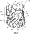
- FIG. 1is a perspective view of a prosthetic heart valve 10, according to one embodiment.
- the illustrated prosthetic valveis adapted to be implanted in the native aortic annulus, although in other embodiments it can be adapted to be implanted in the other native annuluses of the heart.
- the prosthetic valve 10can have three main components: a stent, or frame, 12, a valvular structure 14, and an inner skirt 16.
- the prosthetic valve 10is configured to be radially compressed to a crimped state for delivery into the body of a patient and radially expandable from the crimped state to an expanded state once positioned at the desired implantation location within the body.
- the valvular structure 14can comprise three leaflets 40, collectively forming a leaflet structure, which can be arranged to collapse in a tricuspid arrangement, as best shown in FIG. 3 .
- the leaflets 40can be formed of pericardial tissue (e.g., bovine pericardial tissue), biocompatible synthetic materials, or various other suitable natural or synthetic materials as known in the art and described in U.S. Patent No. 6,730,118 , which is incorporated by reference herein.
- FIG. 4shows a flattened view of the bare frame 12
- FIG. 5shows a perspective view of the bare frame as laser cut from a tubular member, prior to any shape forming.
- the frame 12can be formed with a plurality of circumferentially spaced commissure supports 18 (three in the illustrated embodiment), each of which comprises two axial struts 34 defining a respective slot, or commissure window, 20 therebetween that is adapted to mount the commissures of the valvular structure 14 to the frame, as described in greater detail below.
- the frame 12can be made of any of various suitable plastically-expandable materials (e.g. , stainless steel, etc.) or self-expanding materials (e.g.
- the frame 12When constructed of a plastically-expandable material, the frame 12 (and thus the prosthetic valve 10) can be crimped to a radially compressed state on a delivery catheter and then expanded inside a patient by an inflatable balloon or equivalent expansion mechanism. When constructed of a self-expandable material, the frame 12 (and thus the prosthetic valve 10) can be crimped to a radially compressed state and restrained in the compressed state by insertion into a sheath or equivalent mechanism of a delivery catheter. Once inside the body, the prosthetic valve can be advanced from the delivery sheath, which allows the prosthetic valve to expand to its functional size.
- Suitable plastically-expandable materials that can be used to form the frame 12include, without limitation, stainless steel, a nickel based alloy (e.g. , a cobalt-chromium or a nickel-cobalt-chromium alloy), polymers, or combinations thereof.
- frame 12is made of a nickel-cobalt-chromium-molybdenum alloy, such as MP35N TM (tradename of SPS Technologies), which is equivalent to UNS R30035 (covered by ASTM F562-02).
- MP35N TM /UNS R30035comprises 35% nickel, 35% cobalt, 20% chromium, and 10% molybdenum, by weight.
- MP35Nto form frame 12 provides superior structural results over stainless steel.
- MP35Nwhen MP35N is used as the frame material, less material is needed to achieve the same or better performance in radial and crush force resistance, fatigue resistances, and corrosion resistance.
- the crimped profile of the framecan be reduced, thereby providing a lower profile prosthetic valve assembly for percutaneous delivery to the treatment location in the body.
- the frame 12can also include a plurality of axially extending posts 22 extending from the outflow end of the frame.
- the posts 22are used to form a releasable connection between the prosthetic valve 10 and corresponding components at the distal end of a delivery catheter to retain the prosthetic valve at the end of the delivery catheter until the prosthetic valve is properly positioned at its target deployment location within the body.
- the posts 22typically are used when the frame is a self-expanding frame since there is no balloon to retain the prosthetic valve in place during deployment. If the frame is a plastically-expandable frame that is deployed with a balloon or similar expansion device, the posts 22 typically are not provided. Details of a delivery device that is configured to retain a self-expandable prosthetic valve via posts 22 is disclosed in U.S. Patent Application Publication No. 2010/0049313 , which is incorporated herein by reference.
- the frame 12includes an inflow end 24, an outflow end 26, a lower portion 28 and an upper portion 30.
- the upper portion 30has a tri-lobed cross-sectional shape in a plane perpendicular to the longitudinal axis A of the prosthetic valve at least when the frame is in it expanded state.
- the upper portion 30defines three lobed-shaped portions 32 that mimic the shape of the sinuses of the aortic root.
- the lower portion 28 of the framedesirably has a generally conical or flared shape that tapers from the inflow end 24 toward the upper portion 30 to assist in anchoring the prosthetic valve to the native annulus once implanted.
- the lower portion 28 of the framecan have an overall cylindrical shape from the inflow end 24 to the lower end of the upper portion 30.
- the frame 12is constructed of a self-expandable material (e.g., Nitinol), then the frame can be shape set to assume the shape shown in FIGS. 1-3 when the frame radially expands to its expanded state.
- a specially designed delivery devicecan be used to cause the frame to expand to the shape shown in FIGS. 1-3 .
- One such delivery deviceis shown in FIGS. 9-11 and described below.
- the leaflet assembly 14defines three commissures 42 where the adjacent sides of the leaflets 40 are secured to each other.
- the commissures 42desirably are secured to the upper portion 30 of the frame 12 at locations closest to the longitudinal axis A of the prosthetic valve (which correspond to the locations around the frame where the adjacent ends of the lobed portions 32 meet).
- the frame 12can be provided with commissure window frame portions 18 at these locations of the frame to facilitate attachment of the commissures 42 to the frame.
- Each commissure 42can be formed by securing each leaflet tab 44 ( FIG. 6 ) with an adjacent tab 44 of another leaflet 40.
- the commissures 42can be secured to the frame by inserting each pair of leaflet tabs 44 through a respective slot 20 in a frame portion 18, and securing the leaflet tabs 44 to the axial struts 34, such as with sutures. Further details regarding various techniques for securing the commissures to the window frame portions 18 are disclosed in co-pending U.S. Application No. 13/253,689, filed October 5, 2011 , which is incorporated herein by reference.
- FIG. 6shows a leaflet 40 superimposed over a known leaflet 150 for the same size prosthetic valve.
- the leaflet 40 in the illustrated embodimentincludes a substantially V-shaped lower edge extending between the lower edges of the tabs 44 and a gently curved, or scalloped, upper edge 48 extend between the upper edges of the tabs 44. Because the commissures 42 are secured to the frame 12 at locations spaced radially inwardly toward the longitudinal center axis A relative to the radially outermost sections of the lobed portions 32, the width W of the leaflet (measured between opposing side edges at any location along the height H of the leaflet) can be much less than the width of the leaflet 150.
- the opposing sides of the lower edge 46can have a greater taper (i.e., the width of the lower portion of the leaflet decreases at a greater rate from top to bottom) than the leaflet 150. Consequently, the leaflets 40 are much smaller than typical conventional leaflets for the same size prosthetic valve, and therefore occupy much less space inside the prosthetic valve. As a result, the prosthetic valve 10 can be crimped to a smaller diameter for delivery.
- An important design criterion of a prosthetic heart valveis to prevent or minimize contact between the movable portions of the leaflets and the inner surface of the frame. Repeated contact between the movable portions of the leaflets and the metal frame during operation of the prosthetic valve can cause premature wear and eventual failure of the leaflets.
- To mount a leaflet assembly to a frame having a cylindrical cross sectionit is known, for example, to use additional metal struts or bars or additional layers of material to mount the commissures at locations spaced radially inward from the inner surface of the frame, which assists in preventing contact between the leaflets and the frame.
- additional components or additional layers of material for the mounting the commissurestakes up valuable space inside of the frame and can limit the overall crimping profile of the prosthetic valve.
- the upper portion 30 of the frame 12is shaped such that the commissure support portions of the frame are spaced radially inwardly toward the center axis A of the prosthetic valve relative to the adjacent sections of the frame, without using any additional components or layers of material inside the frame to offset the commissures from the inner surface of the frame.
- the commissures 42 of the leafletsare supported at locations where the ends of the lobed portions 32 meet or converge. As a result, contact between the leaflets 40 and the inner surface of the lobed portions 32 can be avoided during operation of the prosthetic valve. As best shown in FIG.
- the upper free edges 48 of the leafletsare spaced inwardly from the lobed portions 32 by a distance G when the leaflets are open under systolic pressure.
- the prosthetic valve 10can be crimped to a smaller diameter for delivery.
- the commissure supports 18 of the framecan flex slightly radially inwardly and outwardly to reduce stress on the commissure attachment points (the locations were the leaflet tabs 44 are sutured to the frame).
- the leaflets 40can have a scalloped or curved upper edge 48. As a result, the coaptation lines of the leaflets during diastole are lowered, creating a force vector acting downwardly (axially) from the commissures, which reduces stress on the commissure attachment points.
- the prosthetic valve 10desirably is implanted within a native annulus (e.g., the aortic annulus) such that the lower portion 28 of the frame serves as an anchor to retain the prosthetic valve against the native anatomy.
- a native annuluse.g., the aortic annulus
- Most of the upper portion 30 of the frameis positioned above the native annulus and has sufficient flexibility to attain the desired size and shape when expanded regardless of the shape of the native annulus.
- the upper portion 30 of the framecan bend or flex relative to the lower portion 28 in order to expand to its desired functional size and shape to ensure proper operation of the prosthetic valve.
- the upper portioncan fully expand to its desired functional size and shape to ensure proper operation of the prosthetic valve.
- the framealso is less sensitive to under deployment of the upper portion of the frame. Because the commissures of the leaflets are spaced radially inward from the lobed portions, a radial force applied to the upper portion will first compress the lobed portions in the radial direction before the commissures start to move inwardly. That is, the distance between the commissures 42 stays substantially constant as the lobed portions 32 are radially compressed a predetermined amount. In one implementation, the distance between the commissures 42 stays substantially constant when the diameter of the outflow end of the prosthetic valve is reduced by about 2.5 mm.
- the commissures 42can still achieve their functional size, which promotes optimum leaflet performance and increased durability of the leaflets.
- leaflet functionis not effected by a certain degree of under expansion of the frame, a prosthetic valve of a certain size can be implanted in a greater range of annulus sizes.
- the number of prosthetic valve sizes for treating a wide range of patientscan be reduced.
- FIG. 7shows a prosthetic valve 100, according to another embodiment.
- the prosthetic valve 100comprises a frame 102, a valvular structure 14 mounted to the frame 102, and a skirt 16.
- the frame 102has a generally conical or flared lower portion 104 and a tri-lobed shaped upper portion 106 and functions in the manner described above.
- the frame 102comprises a mesh like structure defining a plurality of openings or cells formed by the struts of the frame.
- the frame 102has a substantially homogeneous or uniform structure in that the size and shape of all of the openings are substantially the same.
- the leaflets tabs 44can be sutured to the struts of the frame 102 adjacent the outflow end and the lower edges 46 of the leaflets 40 (not shown in FIG. 7 ) can be sutured to the skirt 16 with sutures, as described above in connection with prosthetic valve 10.
- the frame 102can also include posts 22 (not shown in FIG. 7 ) for connection to a delivery apparatus.
- the main functions of the skirt 16are to assist in securing the valvular structure 14 to the frame 12 and to assist in forming a good seal between the prosthetic valve and the native annulus by blocking the flow of blood through the open cells of the frame 12 below the lower edge of the leaflets.
- the skirt 16desirably comprises a tough, tear resistant material such as polyethylene terephthalate (PET), although various other synthetic or natural materials can be used.
- PETpolyethylene terephthalate
- the thickness of the skirtdesirably is less than 6 mil, and desirably less than 4 mil, and even more desirably about 2 mil.
- the skirt 16can have a variable thickness, for example, the skirt can be thicker at its edges than at its center.
- the skirt 16can comprise a PET skirt having a thickness of about 0.07 mm at its edges and about 0.06 mm at its center. The thinner skirt can provide for better crimping performances while still providing good perivalvular sealing.
- the skirt 16can be secured to the inside of frame 12 via sutures 60.
- Valvular structure 14can be attached to the skirt via one or more thin PET reinforcing strips (not shown) placed along the lower edges 48 of the leaflets, which enable a secure suturing and protects the pericardial tissue of the leaflet structure from tears.
- Valvular structure 14can be sandwiched between skirt 16 and the thin PET strips.
- Suturescan be used to secure the PET strips and the leaflet structure 14 to the skirt 16 along a suture line 62 that tracks the curvature of the bottom edges 48 of the leaflets.
- the skirt 16desirably is woven from a first set of fibers, or yarns or strands, 78 and a second set of fibers, or yarns or strands, 80, both of which are non-perpendicular to the upper edge 82 and the lower edge 84 of the skirt.
- the first set of fibers 78 and the second set of fibers 80extend at angles of about 45 degrees relative to the upper and lower edges 82, 84.
- the skirt 16can be formed by weaving the fibers at 45 degree angles relative to the upper and lower edges of the fabric.
- the skirtcan be diagonally cut from a vertically woven fabric (where the fibers extend perpendicular to the edges of the material) such that the fibers extend at 45 degree angles relative to the cut upper and lower edges of the skirt.
- the opposing short edges 86, 88 of the skirtdesirably are non-perpendicular to the upper and lower edges 82, 84.
- the short edges 86, 88desirably extend at angles of about 45 degrees relative to the upper and lower edges and therefore are aligned with the first set of fibers 78. Therefore the overall shape of the skirt is that of a rhomboid.
- the upper edge portion of the skirt 16can be formed with a plurality of projections 96 that define an undulated shape that generally follows the shape of the row of struts below the commissure portions 18. In this manner, the upper edge of skirt 16 can be tightly secured to the struts with sutures 60. Skirt 16 can also be formed with slits 98 to facilitate attachment of the skirt to the frame. Slits 98 are dimensioned so as to allow an upper edge portion of skirt to be partially wrapped around the struts and reduce stresses in the skirt during the attachment procedure. For example, skirt 16 is placed on the inside of frame 12 and an upper edge portion of the skirt can be wrapped around the upper surfaces of the struts and secured in place with sutures 60. Wrapping the upper edge portion of the skirt around the struts in this manner provides for a stronger and more durable attachment of the skirt to the frame.
- each cell of the metal frame in the illustrated embodimentincludes at least four angled struts that rotate towards the axial direction (i.e. , the angled struts become more aligned with the length of the frame).
- the angled struts of each cellfunction as a mechanism for rotating the fibers of the skirt in the same direction of the struts, allowing the skirt to elongate along the length of the struts. This allows for greater elongation of the skirt and avoids undesirable deformation of the struts when the prosthetic valve is crimped.
- the spacing between the woven fibers or yarnscan be increased to facilitate elongation of the skirt in the axial direction.
- the yarn densitycan be about 15% to about 30% less than a conventional PET skirt.
- the yarn spacing of the skirt 16can be from about 155 yarns per inch to about 180 yarns per inch, such about 160 yarns per inch, whereas in a conventional PET skirt the yarn spacing can be from about 217 yarns per inch to about 247 yarns per inch.
- the oblique edges 86, 88promote uniform and even distribution of the fabric material along inner circumference of the frame during crimping so as to minimize bunching of the fabric to facilitate uniform crimping to the smallest possible diameter. Additionally, cutting diagonal sutures in a vertical manner may leave loose fringes along the cut edges. The oblique edges 86, 88 help minimize this from occurring.
- the prosthetic valves disclosed hereincan also include an outer skirt (not shown) secured to the outside of the frame.
- the outer skirtassists in forming a good seal between the prosthetic valve and the native annulus to avoid perivalvular leaks.
- An outer skirtis further described in co-pending Application No. U.S. Application No. 13/253,689, filed October 5, 2011 , which is incorporated herein by reference.
- a prosthetic valvecan be implanted in known techniques.
- a prosthetic valvecan be implanted in a retrograde approach where the prosthetic valve, mounted in a crimped state at the distal end of a delivery apparatus, is introduced into the body via the femoral artery and advanced through the aortic arch to the heart.
- a prosthetic valvecan also be also be implanted via a transapical approach where the prosthetic valve, mounted in a crimped state at the end of a delivery apparatus, is inserted into the heart via a surgical incision in the chest and the apex of the heart.
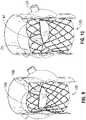
- FIGS. 9 and 10show two possible positions for implanting a prosthetic heart valve of the present disclosure within the native aortic valve.
- FIG. 9shows a first position in which the lobed portions 108 of prosthetic valve 100 are aligned with the native sinuses in the aortic root to fit the native anatomy.
- FIG. 10shows a second position in which the prosthetic valve 100 is rotated 60 degrees from the position shown in FIG. 9 .
- the commissures 42 of the prosthetic valveare generally aligned with the coronary arteries to maximize the space between the openings of the coronary arteries and the outer surface of the prosthetic valve.
- FIGS. 11-12show a balloon assembly 200 of a delivery apparatus, according to one embodiment, that can be used to expand a prosthetic valve to an expanded shape in which the commissure supports 18 are bent radially inwardly relative to the sections of the frame extending between the commissure supports.
- the balloon assembly 200is mounted to the distal end of an elongated shaft 206 of the delivery apparatus.
- the balloon assembly 200 in the illustrated embodimentincludes a center balloon 202 and a plurality of peripheral balloons 204a, 204b surrounding the center balloon.
- the proximal ends of all of the balloonscan be fluidly connected to a central inflation lumen extending through the shaft 206, which allows an inflation fluid to flow into each of the balloons.
- the peripheral balloonsinclude a first set of balloons 204a and a second set of relatively shorter balloons 204b that do not extend the entire length of the balloon assembly. Each of the shorter balloons 204b is positioned between two longer balloons 204a.
- the bare frame 12(without leaflets or skirt) is shown in FIGS. 11 and 12 for purposes of illustration. When the prosthetic valve 10 is crimped and positioned on the balloon assembly 200 for delivery in a patient, the commissure supports 18 are aligned with the tapered ends of the shorter balloons 204b.
- the portion of the frame 12 below the commissure supports 18expands to a cylindrical configuration, while the commissure portions 18 do not fully expand and therefore are titled or bent radially inwardly relative to the struts extending between the commissure portions.
- FIG. 13is a side elevation view of a prosthetic heart valve 300, according to another embodiment.
- FIG. 14is a top plan view of the prosthetic valve 300.
- the illustrated prosthetic valveis adapted to be implanted in the native aortic annulus, although in other embodiments it can be adapted to be implanted in the other native annuluses of the heart.
- the prosthetic valve 300can have three main components: a stent, or frame, 302, a valvular structure 304, and an inner skirt 306.
- the prosthetic valve 300is configured to be radially compressed to a crimped state for delivery into the body of a patient and radially expandable from the crimped state to an expanded state once positioned at the desired implantation location within the body.
- the valvular structure 304can comprise three leaflets 308, collectively forming a leaflet structure, which can be arranged to collapse in a tricuspid arrangement, as best shown in FIG. 14 .
- the leaflets 308can be formed of pericardial tissue (e.g. , bovine pericardial tissue), biocompatible synthetic materials, or various other suitable natural or synthetic materials as known in the art and described in U.S. Patent No. 6,730,118 , which is incorporated by reference herein.
- the frame 302comprises a plurality of longitudinally extending, sinusoidal-shaped or undulating struts 310 connected to each other at nodes 312 so as to define a plurality of open cells arranged in rows along the longitudinal flow axis of the frame.
- the frame 302comprises an inflow end portion 314 that increases in diameter from a diameter D1 at an inflow end of the frame to a relatively larger diameter D2 at a distance spaced from the inflow end of the frame.
- An intermediate portion 316 of the framedefines a "landing zone" for the frame in that the intermediate portion is positioned within the native annulus when the prosthetic valve is deployed.
- the intermediate portioninitially decreases in diameter from diameter D2 to a relatively smaller diameter D3 at about a middle section 318 of the intermediate portion and then increases in diameter to a diameter D4 proximate the outflow end of the frame.
- the middle section 318 of the intermediate portioncan be a cylindrical shape having a relatively constant diameter D3 along the length of the frame between the section that decreases in diameter from diameter D2 to diameter D3 and the section that increases in diameter from D3 to diameter D4.
- An outflow portion 320 of the framedecreases in diameter from diameter D4 at the outflow end of the intermediate portion to a diameter D5 at an outflow end of the frame.
- D2is equal to D4
- D1is equal to D3
- D5is less than D1, D2, D3 and D4.
- FIG. 15shows the frame 302 in a flattened, or unrolled, configuration.
- the outflow end portion 320 of the framecomprises a plurality of circumferentially spaced, longitudinally extending commissure attachment portions, or posts, 322 interspaced between a plurality of frame retaining arms, or posts, 324.
- the retaining arms 324are used to form a releasable connection between the prosthetic valve 300 and corresponding components at the distal end of a delivery catheter to retain the prosthetic valve at the end of the delivery catheter until the prosthetic valve is properly positioned at its target deployment location within the body.
- the retaining arms 324typically are used when the frame is a self-expanding frame since there is no balloon to retain the prosthetic valve in place during deployment. If the frame is a plastically-expandable frame that is deployed with a balloon or similar expansion device, the retaining arms typically are not provided. Details of a delivery device that is configured to retain a self-expandable prosthetic valve via retaining arms 324 is disclosed in U.S. Patent Application Publication No. 2010/0049313 , which is incorporated herein by reference. In the illustrated embodiment, the frame 302 has six such retaining arms 324, although a greater or fewer number of retaining arms may be used.
- the frame 302 in the illustrated embodimenthas three commissure attachment portions 322 corresponding to the three commissures formed by the leaflets 308.
- the framecan have a greater or fewer number of commissure attachment portions 322 if there are a greater or fewer number of commissures formed by the leaflets 308.
- the retaining arms 324 in the illustrated configurationextend generally parallel to the flow axis A of the prosthetic valve, or inwardly at a very small angle (e.g., about 1-2 degrees) with respect to the flow axis A, while the commissure attachment portions 322 extend inwardly at a much sharper angle with respect the flow axis A.
- the commissure attachment portions 322extend inwardly with respect to the flow axis A at an angle of about 10 degrees to about 60 degrees, and more particularly, at an angle of about 15 degrees to about 45 degrees.
- the upper free ends of the commissure attachment portions 322define the outflow diameter D5 of the prosthetic valve.
- the retaining arms 324define a diameter D6, which can be greater than the outflow diameter D5.
- the shape of the frame 302 as depicted in FIG. 13has several advantages.
- the prosthetic valve 300typically is positioned within the sheath of a delivery apparatus such that the inflow end portion 314 is adjacent the distal opening of the sheath.
- the tapered inflow end portion 314can obviate the need for a separate nose cone at the distal end of the delivery apparatus, which typically is used to shield the end of the frame from contacting surrounding tissue during delivery of the prosthetic valve through the patient's vasculature.
- the tapered inflow end portion 3144which typically is deployed first from the sheath during retrograde delivery to the native aortic valve, can reduce the risk of trauma to native tissue, such as the aortic annulus and the native leaflets, as the prosthetic valve is deployed from the sheath.
- the tapered inflow end portionalso reduces the risk of conduction system obstruction.
- the tapered outflow portion 320 of the framereduces the risk of obstructing the coronary ostia when the prosthetic valve is implanted in the native aortic annulus.
- the outflow portionWhen implanted, the outflow portion is spaced inwardly of the aortic root, allowing blood to flow into the coronary arteries.
- the tapered outflow portioncan reduce the risk that calcified native leaflets will be pushed against and block the coronary ostia.
- the tapered outflow portionreduces the risk of interaction with the sinotubular junction.
- the shape of the intermediate section 316facilitates positioning of the prosthetic valve by providing a relative large middle section 318 for positioning within the native annulus.
- the enlarged inflow and outflow sections 326, 328, respectively, of the intermediate section 316assist in centering the prosthetic valve lengthwise with respect to the native annulus.
- the enlarged inflow and outflow sections 326, 328also enhance anchoring of the prosthetic valve by engaging the lower and upper portions of the native valve.
- the inflow section 326can engage the ventricular side of the native aortic valve and inhibit implant migration toward the aorta
- the outflow section 328can engage the aortic side of the native aortic valve and inhibit implant migration toward the left ventricle.
- the intermediate portion 316can provide stable fixation for the prosthetic valve even for a non-calcified aortic root. Moreover, contact between the enlarged inflow section 326 and adjacent tissue and between the enlarged outflow section 328 and adjacent tissue can enhance perivalvular sealing between the skirt 306 and the native annulus.
- the frame designis that is facilitates re-sheathing and/or repositioning of the prosthetic valve.
- the retaining arms 324 of the framecan be secured to connection devices on the distal end of the delivery apparatus when the prosthetic valve is being implanted in the body.
- the prosthetic valveis implanted by deploying the prosthetic valve from the sheath of the delivery apparatus at or near the deployment location, adjusting the position of the prosthetic valve (if necessary) and releasing the connection between the retaining arms 324 and the delivery apparatus.
- the commissure attachment portions 322extend radially inwardly relative to the retaining arms 324, the distal ends of the commissure attachment portions 322 can be retained in a compressed state having a compressed diameter smaller than the inner diameter of the sheath of the delivery apparatus. Thus, even if the prosthetic valve is fully deployed from the delivery sheath, the commissure attachment portions 322 can be retracted back into the sheath, followed by the remaining portion of the prosthetic valve for repositioning the prosthetic valve or withdrawing it from the body.
- FIG. 16is a top plan view of the prosthetic valve 300 with the skirt 306 removed for purposes of illustration.
- FIG. 16also shows the leaflets 308 in an open position under systolic pressure, allowing blood to flow through the prosthetic valve.
- the cantilevered and angled commissure attachment portions 322support respective commissures 330 of the valvular structure inwardly toward the central flow axis A and away from adjacent portions of the frame 302 to avoid contact between the moveable portions of the leaflets and the frame.
- the angled commissure attachment portions 322also reduce the distance between the commissures, enabling a more efficient leaflet design, as further described below.
- the angle of the commissure attachment portions 322can be varied depending on the particular application. FIG.
- FIG. 17shows an embodiment where the commissure attachment portions 322 extend inwardly at about a 60-degree angle relative to the retaining arms 324.
- FIG. 18shows an embodiment where the commissure attachment portions 322 extend inwardly at about a 15-degree angle relative to the retaining arms 324.
- FIG. 19shows a leaflet 308 of the valvular structure 304.
- the leaflet 308 in the illustrated embodimentcomprises a substantially V-shaped or scalloped lower edge 332 extending between the lower edges of tabs 334 and a substantially V-shaped or scalloped upper edge 336 extending between the upper edges of the tabs 334.
- the width W of the leaflet 308(measured between opposing side edges at any location along the height H of the leaflet) can be minimized and the upper edge 336 can have a relatively pronounced concavity, which reduces the overall size of the leaflet compared to a known leaflet 150 ( FIG. 6 ) for the same size prosthetic valve.
- the smaller, more efficient leaflet designoccupies much less space inside the crimped prosthetic valve and therefore allows the prosthetic valve to be crimped to a smaller diameter for delivery.
- commissure attachment portions 322are cantilevered relative to the frame, they can deflect slightly during operation of the prosthetic valve, which improves valve operation and durability.
- the commissure attachment portions 322can deflect inwardly to relieve stress and strain on the leaflets (especially the commissure attachment points of the leaflet tabs 334), which improves long term durability of the leaflets.
- the leaflets open under systolic pressureas depicted in FIG. 16
- the upper edges 336 of the leafletsare retained at a position spaced from the inner surface of the frame to prevent abrasion and increase leaflet durability.
- Providing an enlarged diameter D4 ( FIG. 13 ) within the outflow portion 320 of the framealso assists in creating a gap between the inner surface of the frame and the leaflets when the leaflets are in the open position.
- the cantilevered commissure attachment portions 322can also help avoid “pinwheeling” of the leaflets.
- "Pinwheeling”is a phenomenon characterized by twisting of the upper edges of the leaflets when the leaflets close under diastolic pressure. The twisting motion results in increased flexion and stress on the leaflets, which can adversely effect the durability of the leaflets.
- the flexible commissure attachment portions 322can absorb some of the closing forces on the leaflets and allow the leaflets to close more gently under diastolic pressure, thereby preventing or at least minimizing the pinwheeling effect.
- the concave upper edges 336 of the leaflets and the cantilevered commissure attachment portions 322can also help avoid “reverse bending” of the leaflets.
- "Reverse bending" of leafletsrefers to irregular folds or bends that can occur when the leaflets open under systolic pressure. The stresses generated on the leaflet tissue by such bending or folding of the leaflets can lead to fatigue failure of the leaflet.
- the commissure attachment portions 322are deflect slightly outwardly away from the flow axis A, taking up or reducing slack along the upper edges 336 of the leaflets.
- FIG. 15Ais an enlarged view of a commissure attachment portion 322.
- the commissure attachment portion 322comprises at least two cantilevered struts that are configured to provide a clamping or pinching force against a pair of leaflet tabs 334 to assist in securing the leaflet tabs to the frame.
- each attachment portion 322comprises two cantilevered inner struts 338 and two cantilevered outer struts 340 extending from a common base 342.
- the two inner struts 338are spaced apart from each other to define a leaflet-receiving gap therebetween.
- each outer strut 340is spaced apart from a corresponding adjacent inner strut 338 to define a respective leaflet-receiving gap therebetween.
- the inner and outer struts 338, 340are used to secure the commissures 330 of the leaflets.
- Each outer strut 340can be formed with a small recess or notch 344 that can be used to retain a suture that extends around the attachment portion 322, as further described below.
- Each commissure attachment portion 322supports a pair of adjacent tab portions 334 of two leaflets 308 on the inner and outer struts 338, 340. As best shown in FIG. 23 , a pair of tab portions 334a and 334b extend through the gap between the inner struts 338. On the radial outer side of the commissure attachment portion, the tab portions 334 are folded away from each other, forming a first fold 346a and a second fold 346b. The first fold 346a extends through a respective gap between an inner strut 338 and an adjacent outer strut 340.
- the second fold 346bextends through a respective gap between the inner strut 338 and the adjacent outer strut 340.
- Tab portion 334acan then be folded again to form a fold 348a that lies against the outside of fold 346a.
- tab portion 334bcan be folded again to form a fold 348b that lies against the outside of fold 346b.
- Fold 348acan be secured to fold 346a by a suture 350a that extends along the length of the folds.
- fold 348bcan be secured to fold 346b by a suture 350b that extends along the length of the folds.
- Each pair of the tab portions 334can be reinforced with a reinforcement portion 352, which can be cut or otherwise formed from a sheet of strong, flexible material, such as PET.
- the reinforcement portion 352reinforces the connection of the leaflet tab portions to the frame and protects the portions of the leaflets on the outside of the frame from contacting the delivery sheath.
- the reinforcement portions 352can be three separate pieces of material mounted to the commissure attachment portions 322.
- the reinforcement portions 352can be integral upper extensions of the skirt 306 (i.e., the skirt 306 and the reinforcement portions 352 can be a single piece of material).
- FIG. 20shows a commissure 330 before a reinforcement portion 352 is placed on and secured to the attachment portion 322.
- FIG. 21shows a reinforcement portion 352 in an unfolded configuration prior to being placed on and secured to an attachment portion 322.
- the reinforcement portion 352can be folded partially around a pair of tab portions 334 to form a rear portion 354 ( FIGS. 24-25 ) that extends along the radial outside surface of the commissure attachment portion 322.
- Extending from the longitudinal edges of the rear portion 354are side flaps 356a, 356b.
- side flap 356aextends between leaflet fold 346a and an adjacent outer strut 340 and side flap 356b extends between leaflet fold 346b and an adjacent outer strut 340.
- a top flap 358extends from the upper edge of the rear portion 354 and covers the top of the commissure attachment portion 322.
- a front flap 360extends downwardly from the front edge of the top flap and covers the portion of the commissure attachment portion 322 above the leaflets.
- Two upper side flaps 362extend downwardly from the upper side edges of the top flap 358 and cover the opposite sides of the commissure attachment portion 322 above the leaflets.
- each of the side flaps 362can be a double layer comprising an inner fold and an outer fold.
- the leaflet tab portions 334 and the reinforcement portion 352can be tightly secured to the inner and outer struts 338, 340 by a suture loop 364 ( FIG. 23 ) that is tightened around the upper end portions of the struts 338, 340. Because the struts 338, 340 are cantilevered themselves and unattached to each other at their upper ends, tightening the suture loop 364 draws the struts 338, 340 inwardly toward the longitudinal centerline of the commissure attachment portions 322 (the line equidistant from the inner struts 338), thereby clamping the folds of the leaflets and the reinforcement portion between the struts 338, 340.
- the suture loop 364can be located within the notches 344 ( FIG. 15A ) of the outer struts 340, which prevent the loop 364 from sliding along the length of the struts.
- Another suture loop 366( FIGS. 24 and 25 ) can be tightened around the lower end of the commissure attachment portion 322 and lower end portion of the reinforcement portion 352.
- each leaflet 308can be secured to the skirt 306 along a suture line 368 ( FIG. 13 ).
- the lowermost sections of the lower edges 332 of the leaflets(indicated by suture line 368) desirably are aligned with the inflow edge of the frame 302. In this manner, the leaflets 308 extend the entire length or substantially the entire length of the frame from the inlet end to the outlet end of the frame.
- the skirt 306can be secured directly to the frame 302 with sutures (not shown), in the same manner that skirt 16 ( FIG. 1 ) is secured to the frame 12 with sutures 60.
- the process suturing leaflet commissures to a frameis a time-consuming and tedious process.
- the struts 338, 340 of the commissure attachment portionsare advantageous in that they provide a robust attachment for the leaflet tab portions 334 while significantly minimizing the extent of suturing required to secure the leaflet commissures to the frame compared to known techniques.
- only two suture loops 364, 366are used to secure a reinforcement portion 352 to a commissure attachment portion 322 and to a pair of leaflet tab portions 334, and other than sutures 350a, 350b, no further stitching is required to secure together multiple folds of the leaflet to each other or to the folds of the reinforcement portion 352.
- commissure attachment portionsare minimize the amount of leaflet material positioned on the outside of the frame. This reduces friction between the outside of the prosthetic valve and the deliver sheath, such as when the prosthetic valve is deployed from the sheath. Moreover, if the prosthetic valve is retracted back into the sheath after its initial deployment, the prosthetic valve can slide more easily back into the sheath while minimizing the risk of damage to the leaflet material on the outside of the frame that may occur from contact with the distal end of the sheath.
- FIG. 26shows another embodiment of a frame 400 that can be used in the prosthetic valve 300.
- Frame 400is similar to frame 302 ( FIG. 15 ), except for the number of cells bridging the intermediate portion 316 and the outflow portion 320.
- each row 370 of cells of the frameincludes twelve cells 372.
- the uppermost row 402 of cells bridging the intermediate portion 316 and the outflow portion 320includes six cells 404, which reduces the amount of metal in that portion of the frame.
- the uppermost row 402 of cellscircumscribes the widest portion of the leaflets (except for the tab portions 334) and therefore corresponds to the volume occupied by the bulk of the leaflets when the prosthetic valve is radially crimped. Therefore, the removal of metal from the frame, and in particular from the portion of the frame circumscribing the widest portion of the leaflets, allows for a smaller crimped diameter for the prosthetic valve.
- FIG. 27illustrates an embodiment of a prosthetic valve 500, which is described in detail in U.S. Patent No. 7,993,394 , which is incorporated herein by reference.
- the prosthetic valve 500can have three main components: a stent, or frame, 502, a valvular structure 504, and an inner skirt 506.
- the prosthetic valve 500is configured to be radially compressed to a crimped state for delivery into the body of a patient and radially expandable from the crimped state to an expanded state once positioned at the desired implantation location within the body.
- the valvular structure 504can comprise three leaflets 508, collectively forming a leaflet structure, which can be arranged to collapse in a tricuspid arrangement, as shown.
- FIG. 28is an enlarged view of a section of the prosthetic valve 500 showing the connection of a commissure 510 of two adjacent leaflets 508 to the frame.
- the commissure 510is formed by securing a pair of leaflet tab portions 512 to each other and to a commissure attachment post 514 of the frame 502 with sutures 520.
- the lower edges of the leaflets 508can be sutured to the skirt 506 along a suture line 516, and the skirt 506 can be secured to the frame 502 with sutures 518.
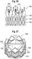
- FIG. 29shows a stent, or frame, 600 according to another embodiment that can be used in the prosthetic valve 500 of FIGS. 27 and 28 .
- the frame 600is a plastically-expandable frame (i.e., is expanded with a balloon or equivalent mechanism) and is configured to undergo post-deployment shaping after being deployed in a patient's body.
- the frame 600 in the illustrated configurationis configured to be deployed into a generally cylindrical configuration using a conventional cylindrical balloon, and after deflating and removing the balloon, the commissure attachment portions can bend inwardly to support the commissures of the leaflets at locations closer to the central flow axis of the prosthetic valve.
- a prosthetic valvecan comprise the frame 600 and the leaflet structure 304 comprising leaflets 308 of the prosthetic valve 300.
- FIG. 29shows the frame 600 in a radially expanded state after being expanded by an inflatable balloon of a balloon catheter.
- the ballooncan be a conventional balloon that assumes a generally cylindrical shape when inflated.
- the frame 600can assume a generally cylindrical shape when expanded by the balloon.
- the frame 600 in the illustrated configurationcomprises a plurality of commissure attachment posts, or struts, 602 (three in the illustrated embodiment), a first row of struts 604 at the inflow end of the frame, and a second row of struts 606 and a third row of struts 608 at the outflow end of the frame.
- a plurality of longitudinal struts 610extend between the apices of the first row of struts 604 and nodes 612 adjoining adjacent cells formed by struts 606 and 608.
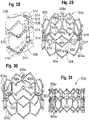
- the frame 600is configured to permit inward titling or displacement of the upper portions 614 of the commissure attachment posts 602 when they are first subjected to a closing force of the leaflets under diastolic pressure and then remain in the tilted position.
- struts 606a and 608a that are connected directly to the commissure attachment posts 602can be weakened relative to the other struts by reducing or thinning the cross-sectional profile of the struts 606a, 608a, such as by reducing the thickness and/or width of the struts 606a, 608a, and by providing one or more curves or bends in the struts 606a, 608a.
- the curves or bends in the struts 606a, 608aprovide slack in those struts to permit the commissure attachment posts 602 to flex inwardly relative to longitudinal struts 610.
- the frame 600When the prosthetic valve is first deployed within the native aortic valve (or another native heart valve) by inflating a balloon, the frame 600 is expanded to the expanded shape shown in FIG. 29 .
- diastolic pressurecauses the leaflets (e.g., leaflets 508) to close, and the closing force of the leaflets draws the upper portions 614 of the commissure attachment posts 602 to bend or tilt inwardly to the positions shown in FIGS. 30 and 31 .
- the struts 606a, 608aare straightened and limit further bending of the posts 602.
- the struts 606a, 608a in their straightened or nearly straightened configurationexhibit sufficient rigidity to retain the posts 602 in their titled position under systolic pressure.
- the posts 602remain their titled position supporting the commissures (e.g., commissures 510) closer to the longitudinal flow axis of the prosthetic valve.
- a plastically-expandable prosthetic valve incorporating the frame 600can achieve an overall shape similar to that shown in FIGS. 11 and 12 without a specially shaped balloon assembly.
- the inwardly canted posts 602support the moveable portions of the leaflets away from the inner surface of the frame 600 when the leaflets are in the open position, thereby protecting the leaflets against abrasion caused by contact between the leaflets and the frame, as previously discussed.
- the struts 604a of the first row that are connected directly to the posts 602can have a configuration similar to posts 606a, 608a. Weakening the struts 604a connected to the lower ends of posts 602 can facilitate displacement of the posts 602 by allowing for slight outward deflection of the lower ends of the posts 602.
- the posts 602can be weakened at one or more selected locations to facilitate displacement of the posts. As shown in FIGS. 32 and 33 , for example, each post 602 can have a slit, or recessed portion, 616 formed in the inner surface of the post at a location just above the first row of struts 604.
- the recessed portions 616weakens the posts 602 and function as a pivot for the posts, allowing the posts to more easily bend at the recessed portions 616 when subjected to the force of the initial closing of the leaflets.
- the posts 602can be weakened by reducing the width and/or the thickness of the posts at selected locations to facilitate displacement of the posts.
- FIG. 34A modification of the frame 600 is shown in FIG. 34 .
- tether or wires 618can be used to limit the extent of inward displacement of the upper end portions of the posts.
- each post 602can be connected to a pair of wires 618, each having one end secured to an apex 620 of the third row of struts and another end secured to the upper end portion 614 of the post 602.
- the frameis initially expanded and before subjected to the closing force of the leaflets, there is sufficient slack in the wires 618 to allow the posts 602 to bend inwardly.
- the length of the wires 618is selected to allow the posts 602 to bend or tilt inwardly a limited amount when subjected to the force of the initial closing of the leaflets. Upon initial closing of the leaflets, the wires 618 are pulled taught and limit the extent to which the upper end portions of the posts 602 can be pulled inwardly by the force of the leaflets.
Landscapes
- Health & Medical Sciences (AREA)
- Cardiology (AREA)
- Engineering & Computer Science (AREA)
- Biomedical Technology (AREA)
- Heart & Thoracic Surgery (AREA)
- Transplantation (AREA)
- Oral & Maxillofacial Surgery (AREA)
- Vascular Medicine (AREA)
- Life Sciences & Earth Sciences (AREA)
- Animal Behavior & Ethology (AREA)
- General Health & Medical Sciences (AREA)
- Public Health (AREA)
- Veterinary Medicine (AREA)
- Mechanical Engineering (AREA)
- Prostheses (AREA)
Abstract
Description
- The present disclosure concerns embodiments of a prosthetic heart valve, and delivery systems for implanting prosthetic heart valves.
- The human heart can suffer from various valvular diseases. These valvular diseases can result in significant malfunctioning of the heart and ultimately require replacement of the native valve with an artificial valve. There are a number of known artificial valves and a number of known methods of implanting these artificial valves in humans.
- Various surgical techniques may be used to replace or repair a diseased or damaged native valve. Due to stenosis and other heart valve diseases, thousands of patients undergo surgery each year wherein the defective native heart valve is replaced by a prosthetic valve. Another less drastic method for treating defective valves is through repair or reconstruction, which is typically used on minimally calcified valves. The problem with surgical therapy is the significant risk it imposes on these chronically ill patients with high morbidity and mortality rates associated with surgical repair.
- When the native valve is replaced, surgical implantation of the prosthetic valve typically requires an open-chest surgery during which the heart is stopped and patient placed on cardiopulmonary bypass (a so-called "heart-lung machine"). In one common surgical procedure, the diseased native valve leaflets are excised and a prosthetic valve is sutured to the surrounding tissue at the native valve annulus. Because of the trauma associated with the procedure and the attendant duration of extracorporeal blood circulation, some patients do not survive the surgical procedure or die shortly thereafter. It is well known that the risk to the patient increases with the amount of time required on extracorporeal circulation. Due to these risks, a substantial number of patients with defective native valves are deemed inoperable because their condition is too frail to withstand the procedure. By some estimates, more than 50% of the subjects suffering from valve stenosis who are older than 80 years cannot be operated on for valve replacement.
- Because of the drawbacks associated with conventional open-heart surgery, percutaneous and minimally-invasive surgical approaches are garnering intense attention. In one technique, a prosthetic valve is configured to be implanted in a much less invasive procedure by way of catheterization. For instance,
U.S. Patent Nos. 5,411,522 and6,730,118 , which are incorporated herein by reference, describe collapsible transcatheter prosthetic heart valves that can be percutaneously introduced in a compressed state on a catheter and expanded in the desired position by balloon inflation or by utilization of a self-expanding frame or stent. - An important design parameter of a transcatheter prosthetic heart valve is the diameter of the folded or crimped profile. The diameter of the crimped profile is important because it directly influences the physician's ability to advance the transcatheter prosthetic heart valve through the femoral artery or vein. More particularly, a smaller profile allows for treatment of a wider population of patients, with enhanced safety.
- The present disclosure is directed to embodiments of catheter-based prosthetic heart valves. A prosthetic heart valve according to the present disclosure comprises a radially collapsible and expandable annular frame and a leaflet structure comprising a plurality of leaflets mounted within the frame. The frame in particular embodiments can have commissure attachment portions that are configured to support the commissures of the leaflets at locations spaced radially inwardly toward the longitudinal flow axis of the prosthetic valve relative to the frame portions circumscribing the moveable portions of the leaflets. When the leaflets open under pressure of blood flowing through the prosthetic valve, the moveable portions of the leaflets are retained at positions spaced inwardly from the inner surface of the frame to protect against abrasion of the leaflets.
- In one representative embodiment, a prosthetic valve comprises a radially collapsible and expandable annular frame. The frame has a plurality of angularly spaced commissure attachment portions and a plurality of lobed portions extending between the commissure attachment portions. The frame also has an inlet end and an outlet end. A leaflet structure comprises a plurality of leaflets, each leaflet comprising opposing side portions and an upper edge extending between the side portions. Each side portion is secured to an adjacent side portion of another leaflet to form commissures of the leaflet structure, each commissure being attached to one of the commissure attachment portions of the frame. The leaflets are configured to move between an open position to allow blood to flow through the prosthetic valve from the inlet end to the outlet end and a closed position to inhibit the flow of blood through the prosthetic valve from the outlet end to the inlet end, wherein the upper edges of the leaflets are spaced radially inwardly of the lobed portion of the frame when the leaflets are in the open position.
- In another representative embodiment, a prosthetic valve comprises a radially collapsible and expandable annular frame. The frame comprises an inlet portion and an outlet portion, the outlet portion comprising a plurality of angularly spaced, cantilevered commissure attachment posts extending radially inwardly toward a longitudinal flow axis of the prosthetic valve. A leaflet structure comprises a plurality of leaflets, each leaflet comprising opposing side portions, a scalloped upper edge extending between the side portions, and a scalloped lower edge extending between the side portions. Each side portion is secured to an adjacent side portion of another leaflet to form commissures of the leaflet structure, each commissure being attached to one of the commissure attachment posts. The leaflets are configured to move between an open position to allow blood to flow through the prosthetic valve from the inlet portion to the outlet portion and a closed position to inhibit the flow of blood through the prosthetic valve from the outlet portion to the inlet portion, wherein the upper edges of the leaflets are spaced radially inwardly of the frame when the leaflets are in the open position such that a gap is formed between the upper edge of each leaflet and the frame.
- In another representative embodiment, a prosthetic valve comprises a radially collapsible and expandable annular frame. The frame has a plurality of angularly spaced commissure attachment posts, each commissure attachment post comprising at least two cantilevered struts spaced apart from each other to define a leaflet-receiving gap. A leaflet structure comprises a plurality of leaflets, each leaflet comprising opposing side portions and an upper edge extending between the side portions. Each side portion is secured to an adjacent side portion of another leaflet to form commissures of the leaflet structure. Each commissure extends through the leaflet-receiving gap of a respective commissure attachment post, and the struts of the commissure attachment post are compressed toward each to clamp the commissure between the struts.
- In another representative embodiment, a prosthetic valve comprises a radially collapsible and expandable annular frame that is plastically expandable. The frame comprises a plurality of angularly spaced commissure attachment posts. A leaflet structure comprises a plurality of leaflets, each leaflet comprising opposing side portions, wherein each side portion is secured to an adjacent side portion of another leaflet to form commissures of the leaflet structure, each commissure being attached to one of the commissure attachment posts. The commissure attachment posts are configured to deflect radially inwardly toward a longitudinal flow axis of the prosthetic valve when first subjected to closing forces of the leaflets immediately following implantation of the prosthetic valve and then remain in the deflected position during subsequent closing and opening cycles of the prosthetic valve.
- The foregoing and other objects, features, and advantages of the invention will become more apparent from the following detailed description, which proceeds with reference to the accompanying figures.
FIG. 1 is a perspective view of a prosthetic heart valve, according to one embodiment.FIG. 2 is a top plan view of the prosthetic heart valve ofFIG. 1 , showing the leaflets in the open position.FIG. 3 is a top plan view of the prosthetic heart valve ofFIG. 1 , showing the leaflets in the closed position.FIG. 4 is a flattened view of the frame of the prosthetic heart valve ofFIG. 1 , as laser cut from a tubular member.FIG. 5 is a perspective view of the frame ofFIG. 4 , as laser cut from a tubular member.FIG. 6 shows a leaflet of the prosthetic heart valve ofFIG. 1 , shown on top of a known leaflet for purposes of comparison.FIG. 7 is a perspective view of a prosthetic heart valve, according to another embodiment.FIG. 8 shows a flattened view of a skirt for a prosthetic heart valve, according to one embodiment.FIGS. 9 and 10 show two positions for implanting a prosthetic heart valve in the aortic annulus.FIG. 11 is a side view of a balloon assembly of a delivery apparatus, according to one embodiment, that can be used for implanting a prosthetic heart valve.FIG. 12 is a top plan view of the balloon assembly ofFIG. 11 .FIG. 13 is a side elevation of a prosthetic heart valve, according to another embodiment.FIG. 14 is a top plan view of the prosthetic valve shown inFIG. 13 , showing the leaflets in the closed position.FIG. 15 is a flattened view of the frame of the prosthetic valve shown inFIG. 13 .FIG. 15A is an enlarged view of a portion of the frame shown inFIG. 15 .FIG. 16 is a top plan view of the prosthetic valve ofFIG. 13 , showing the leaflets in the open position.FIG. 17 is a perspective view of a leaflet and a portion of the frame of the prosthetic valve ofFIG. 13 , showing the commissure of the leaflet supported at angle of about 60 degrees relative to the longitudinal flow axis of the valve.FIG. 18 is a perspective view similar toFIG. 17 , showing the commissure of the leaflet supported at an angle of about 15 degrees relative to the longitudinal flow axis of the prosthetic valve.FIG. 19 is a flattened view of a leaflet of the prosthetic valve ofFIG. 13 .FIGS. 20-25 are various views illustrating the connection of a commissure to the frame of the prosthetic valve ofFIG. 13 .FIG. 26 is a flattened view of another embodiment of a frame that can be used in the prosthetic valve ofFIG. 13 .FIG. 27 is a perspective view of a prosthetic heart valve, according to another embodiment.FIG. 28 is an enlarged view of a section of the prosthetic valve ofFIG. 27 , showing the connection of a commissure to the frame of the valve.FIG. 29 is a perspective view of another embodiment of a frame that can be used in the prosthetic valve ofFIG. 27 , showing the frame in an expanded state immediately after deployment by a balloon.FIG. 30 is a perspective view of the frame ofFIG. 29 , showing the frame after the commissure posts are displaced by the closing forces of the leaflets.FIG. 31 is a side elevation view of the frame ofFIG. 30 .FIG. 32 is a cross-sectional view of the frame ofFIG. 31 .FIG. 33 is an enlarged view of a weakened portion of the commissure post of the frame shown inFIG. 32 .FIG. 34 is a perspective view of an alternative embodiment of the frame shown inFIG. 29 .- The present disclosure is directed to embodiments of catheter-based prosthetic heart valves. Several exemplary embodiments of prosthetic heart valves are disclosed herein and shown in the attached figures. These embodiments should not be construed as limiting in any way. Instead, the present disclosure is directed toward all novel and nonobvious features and aspects of the various disclosed embodiments, alone and in various combinations and sub-combinations with one another.
FIG. 1 is a perspective view of aprosthetic heart valve 10, according to one embodiment. The illustrated prosthetic valve is adapted to be implanted in the native aortic annulus, although in other embodiments it can be adapted to be implanted in the other native annuluses of the heart. Theprosthetic valve 10 can have three main components: a stent, or frame, 12, avalvular structure 14, and aninner skirt 16. Theprosthetic valve 10 is configured to be radially compressed to a crimped state for delivery into the body of a patient and radially expandable from the crimped state to an expanded state once positioned at the desired implantation location within the body.- The
valvular structure 14 can comprise threeleaflets 40, collectively forming a leaflet structure, which can be arranged to collapse in a tricuspid arrangement, as best shown inFIG. 3 . Theleaflets 40 can be formed of pericardial tissue (e.g., bovine pericardial tissue), biocompatible synthetic materials, or various other suitable natural or synthetic materials as known in the art and described inU.S. Patent No. 6,730,118 , which is incorporated by reference herein. FIG. 4 shows a flattened view of thebare frame 12 andFIG. 5 shows a perspective view of the bare frame as laser cut from a tubular member, prior to any shape forming. Theframe 12 can be formed with a plurality of circumferentially spaced commissure supports 18 (three in the illustrated embodiment), each of which comprises twoaxial struts 34 defining a respective slot, or commissure window, 20 therebetween that is adapted to mount the commissures of thevalvular structure 14 to the frame, as described in greater detail below. Theframe 12 can be made of any of various suitable plastically-expandable materials (e.g., stainless steel, etc.) or self-expanding materials (e.g., Nitinol) as known in the art. When constructed of a plastically-expandable material, the frame 12 (and thus the prosthetic valve 10) can be crimped to a radially compressed state on a delivery catheter and then expanded inside a patient by an inflatable balloon or equivalent expansion mechanism. When constructed of a self-expandable material, the frame 12 (and thus the prosthetic valve 10) can be crimped to a radially compressed state and restrained in the compressed state by insertion into a sheath or equivalent mechanism of a delivery catheter. Once inside the body, the prosthetic valve can be advanced from the delivery sheath, which allows the prosthetic valve to expand to its functional size.- Suitable plastically-expandable materials that can be used to form the
frame 12 include, without limitation, stainless steel, a nickel based alloy (e.g., a cobalt-chromium or a nickel-cobalt-chromium alloy), polymers, or combinations thereof. In particular embodiments,frame 12 is made of a nickel-cobalt-chromium-molybdenum alloy, such as MP35N™ (tradename of SPS Technologies), which is equivalent to UNS R30035 (covered by ASTM F562-02). MP35N™/UNS R30035 comprises 35% nickel, 35% cobalt, 20% chromium, and 10% molybdenum, by weight. It has been found that the use of MP35N to formframe 12 provides superior structural results over stainless steel. In particular, when MP35N is used as the frame material, less material is needed to achieve the same or better performance in radial and crush force resistance, fatigue resistances, and corrosion resistance. Moreover, since less material is required, the crimped profile of the frame can be reduced, thereby providing a lower profile prosthetic valve assembly for percutaneous delivery to the treatment location in the body. - The
frame 12 can also include a plurality of axially extendingposts 22 extending from the outflow end of the frame. Theposts 22 are used to form a releasable connection between theprosthetic valve 10 and corresponding components at the distal end of a delivery catheter to retain the prosthetic valve at the end of the delivery catheter until the prosthetic valve is properly positioned at its target deployment location within the body. Theposts 22 typically are used when the frame is a self-expanding frame since there is no balloon to retain the prosthetic valve in place during deployment. If the frame is a plastically-expandable frame that is deployed with a balloon or similar expansion device, theposts 22 typically are not provided. Details of a delivery device that is configured to retain a self-expandable prosthetic valve viaposts 22 is disclosed inU.S. Patent Application Publication No. 2010/0049313 , which is incorporated herein by reference. - Referring to
FIG. 1 , theframe 12 includes aninflow end 24, anoutflow end 26, alower portion 28 and anupper portion 30. As best shown inFIGS. 2 and 3 , theupper portion 30 has a tri-lobed cross-sectional shape in a plane perpendicular to the longitudinal axis A of the prosthetic valve at least when the frame is in it expanded state. Theupper portion 30 defines three lobed-shapedportions 32 that mimic the shape of the sinuses of the aortic root. Thelower portion 28 of the frame desirably has a generally conical or flared shape that tapers from theinflow end 24 toward theupper portion 30 to assist in anchoring the prosthetic valve to the native annulus once implanted. In other embodiments, thelower portion 28 of the frame can have an overall cylindrical shape from theinflow end 24 to the lower end of theupper portion 30. If theframe 12 is constructed of a self-expandable material (e.g., Nitinol), then the frame can be shape set to assume the shape shown inFIGS. 1-3 when the frame radially expands to its expanded state. If theframe 12 is constructed of a plastically-expandable material, then a specially designed delivery device can be used to cause the frame to expand to the shape shown inFIGS. 1-3 . One such delivery device is shown inFIGS. 9-11 and described below. - The
leaflet assembly 14 defines threecommissures 42 where the adjacent sides of theleaflets 40 are secured to each other. Thecommissures 42 desirably are secured to theupper portion 30 of theframe 12 at locations closest to the longitudinal axis A of the prosthetic valve (which correspond to the locations around the frame where the adjacent ends of thelobed portions 32 meet). Theframe 12 can be provided with commissurewindow frame portions 18 at these locations of the frame to facilitate attachment of thecommissures 42 to the frame. Eachcommissure 42 can be formed by securing each leaflet tab 44 (FIG. 6 ) with anadjacent tab 44 of anotherleaflet 40. Thecommissures 42 can be secured to the frame by inserting each pair ofleaflet tabs 44 through arespective slot 20 in aframe portion 18, and securing theleaflet tabs 44 to theaxial struts 34, such as with sutures. Further details regarding various techniques for securing the commissures to thewindow frame portions 18 are disclosed in co-pendingU.S. Application No. 13/253,689, filed October 5, 2011 FIG. 6 shows aleaflet 40 superimposed over a knownleaflet 150 for the same size prosthetic valve. As shown, theleaflet 40 in the illustrated embodiment includes a substantially V-shaped lower edge extending between the lower edges of thetabs 44 and a gently curved, or scalloped,upper edge 48 extend between the upper edges of thetabs 44. Because thecommissures 42 are secured to theframe 12 at locations spaced radially inwardly toward the longitudinal center axis A relative to the radially outermost sections of thelobed portions 32, the width W of the leaflet (measured between opposing side edges at any location along the height H of the leaflet) can be much less than the width of theleaflet 150. Similarly, the opposing sides of thelower edge 46 can have a greater taper (i.e., the width of the lower portion of the leaflet decreases at a greater rate from top to bottom) than theleaflet 150. Consequently, theleaflets 40 are much smaller than typical conventional leaflets for the same size prosthetic valve, and therefore occupy much less space inside the prosthetic valve. As a result, theprosthetic valve 10 can be crimped to a smaller diameter for delivery.- An important design criterion of a prosthetic heart valve is to prevent or minimize contact between the movable portions of the leaflets and the inner surface of the frame. Repeated contact between the movable portions of the leaflets and the metal frame during operation of the prosthetic valve can cause premature wear and eventual failure of the leaflets. To mount a leaflet assembly to a frame having a cylindrical cross section, it is known, for example, to use additional metal struts or bars or additional layers of material to mount the commissures at locations spaced radially inward from the inner surface of the frame, which assists in preventing contact between the leaflets and the frame. Unfortunately, the use of additional components or additional layers of material for the mounting the commissures takes up valuable space inside of the frame and can limit the overall crimping profile of the prosthetic valve.
- To address these concerns, the
upper portion 30 of theframe 12 is shaped such that the commissure support portions of the frame are spaced radially inwardly toward the center axis A of the prosthetic valve relative to the adjacent sections of the frame, without using any additional components or layers of material inside the frame to offset the commissures from the inner surface of the frame. As noted above, thecommissures 42 of the leaflets are supported at locations where the ends of thelobed portions 32 meet or converge. As a result, contact between theleaflets 40 and the inner surface of thelobed portions 32 can be avoided during operation of the prosthetic valve. As best shown inFIG. 2 , the upperfree edges 48 of the leaflets are spaced inwardly from thelobed portions 32 by a distance G when the leaflets are open under systolic pressure. Advantageously, since the shape of the frame itself supports thecommissures 42 radially inward of the frame sections between the commissure supports 18 without additional components inside of the prosthetic valve, theprosthetic valve 10 can be crimped to a smaller diameter for delivery. - Also due to the shape of the frame, during operation of the prosthetic valve, the commissure supports 18 of the frame can flex slightly radially inwardly and outwardly to reduce stress on the commissure attachment points (the locations were the
leaflet tabs 44 are sutured to the frame). As noted above, theleaflets 40 can have a scalloped or curvedupper edge 48. As a result, the coaptation lines of the leaflets during diastole are lowered, creating a force vector acting downwardly (axially) from the commissures, which reduces stress on the commissure attachment points. - The
prosthetic valve 10 desirably is implanted within a native annulus (e.g., the aortic annulus) such that thelower portion 28 of the frame serves as an anchor to retain the prosthetic valve against the native anatomy. Most of theupper portion 30 of the frame is positioned above the native annulus and has sufficient flexibility to attain the desired size and shape when expanded regardless of the shape of the native annulus. For example, in the case of an oval native annulus, theupper portion 30 of the frame can bend or flex relative to thelower portion 28 in order to expand to its desired functional size and shape to ensure proper operation of the prosthetic valve. In the case of a relatively small native annulus, which can prevent full deployment of thelower portion 28, the upper portion can fully expand to its desired functional size and shape to ensure proper operation of the prosthetic valve. - The frame also is less sensitive to under deployment of the upper portion of the frame. Because the commissures of the leaflets are spaced radially inward from the lobed portions, a radial force applied to the upper portion will first compress the lobed portions in the radial direction before the commissures start to move inwardly. That is, the distance between the
commissures 42 stays substantially constant as thelobed portions 32 are radially compressed a predetermined amount. In one implementation, the distance between thecommissures 42 stays substantially constant when the diameter of the outflow end of the prosthetic valve is reduced by about 2.5 mm. Thus, if the upper portion of the frame is slightly under expanded due to the positioning of the prosthetic valve and/or the shape of the native annulus, thecommissures 42 can still achieve their functional size, which promotes optimum leaflet performance and increased durability of the leaflets. Similarly, because leaflet function is not effected by a certain degree of under expansion of the frame, a prosthetic valve of a certain size can be implanted in a greater range of annulus sizes. Thus, the number of prosthetic valve sizes for treating a wide range of patients can be reduced. - The spaces between the
skirt 16 and the outer surfaces of theleaflets 40 within thelobed portions 32 of the frame create artificial sinuses that are shaped similar to and mimic the Valsalva sinuses. Thus, when the leaflets close, backflow entering these artificial sinuses create a turbulent flow of blood along the upper surfaces of the leaflets. This turbulence assists in washing the leaflets and the skirt to minimize clot formation. - The
commissures 42 can also be secured to a frame that does not have anywindow frame portions 18.FIG. 7 , for example, shows aprosthetic valve 100, according to another embodiment. Theprosthetic valve 100 comprises aframe 102, avalvular structure 14 mounted to theframe 102, and askirt 16. Like theframe 12 described above, theframe 102 has a generally conical or flaredlower portion 104 and a tri-lobed shapedupper portion 106 and functions in the manner described above. Theframe 102 comprises a mesh like structure defining a plurality of openings or cells formed by the struts of the frame. Theframe 102 has a substantially homogeneous or uniform structure in that the size and shape of all of the openings are substantially the same. Theleaflets tabs 44 can be sutured to the struts of theframe 102 adjacent the outflow end and thelower edges 46 of the leaflets 40 (not shown inFIG. 7 ) can be sutured to theskirt 16 with sutures, as described above in connection withprosthetic valve 10. Theframe 102 can also include posts 22 (not shown inFIG. 7 ) for connection to a delivery apparatus. - The main functions of the
skirt 16 are to assist in securing thevalvular structure 14 to theframe 12 and to assist in forming a good seal between the prosthetic valve and the native annulus by blocking the flow of blood through the open cells of theframe 12 below the lower edge of the leaflets. Theskirt 16 desirably comprises a tough, tear resistant material such as polyethylene terephthalate (PET), although various other synthetic or natural materials can be used. The thickness of the skirt desirably is less than 6 mil, and desirably less than 4 mil, and even more desirably about 2 mil. In particular embodiments, theskirt 16 can have a variable thickness, for example, the skirt can be thicker at its edges than at its center. In one implementation, theskirt 16 can comprise a PET skirt having a thickness of about 0.07 mm at its edges and about 0.06 mm at its center. The thinner skirt can provide for better crimping performances while still providing good perivalvular sealing. - As shown in
FIG. 1 , theskirt 16 can be secured to the inside offrame 12 viasutures 60.Valvular structure 14 can be attached to the skirt via one or more thin PET reinforcing strips (not shown) placed along thelower edges 48 of the leaflets, which enable a secure suturing and protects the pericardial tissue of the leaflet structure from tears.Valvular structure 14 can be sandwiched betweenskirt 16 and the thin PET strips. Sutures can be used to secure the PET strips and theleaflet structure 14 to theskirt 16 along asuture line 62 that tracks the curvature of thebottom edges 48 of the leaflets. - Referring to
FIG. 8 , in contrast to known fabric skirts, theskirt 16 desirably is woven from a first set of fibers, or yarns or strands, 78 and a second set of fibers, or yarns or strands, 80, both of which are non-perpendicular to theupper edge 82 and thelower edge 84 of the skirt. In particular embodiments, the first set offibers 78 and the second set offibers 80 extend at angles of about 45 degrees relative to the upper andlower edges skirt 16 can be formed by weaving the fibers at 45 degree angles relative to the upper and lower edges of the fabric. Alternatively, the skirt can be diagonally cut from a vertically woven fabric (where the fibers extend perpendicular to the edges of the material) such that the fibers extend at 45 degree angles relative to the cut upper and lower edges of the skirt. As further shown inFIG. 8 , the opposingshort edges lower edges short edges fibers 78. Therefore the overall shape of the skirt is that of a rhomboid. - The upper edge portion of the
skirt 16 can be formed with a plurality ofprojections 96 that define an undulated shape that generally follows the shape of the row of struts below thecommissure portions 18. In this manner, the upper edge ofskirt 16 can be tightly secured to the struts withsutures 60.Skirt 16 can also be formed withslits 98 to facilitate attachment of the skirt to the frame.Slits 98 are dimensioned so as to allow an upper edge portion of skirt to be partially wrapped around the struts and reduce stresses in the skirt during the attachment procedure. For example,skirt 16 is placed on the inside offrame 12 and an upper edge portion of the skirt can be wrapped around the upper surfaces of the struts and secured in place withsutures 60. Wrapping the upper edge portion of the skirt around the struts in this manner provides for a stronger and more durable attachment of the skirt to the frame. - Due to the orientation of the fibers relative to the upper and lower edges, the skirt can undergo greater elongation in the axial direction (i.e., in a direction from the
upper edge 82 to the lower edge 84). Thus, when themetal frame 12 is crimped, theskirt 16 can elongate in the axial direction along with the frame and therefore provides a more uniform and predictable crimping profile. Each cell of the metal frame in the illustrated embodiment includes at least four angled struts that rotate towards the axial direction (i.e., the angled struts become more aligned with the length of the frame). The angled struts of each cell function as a mechanism for rotating the fibers of the skirt in the same direction of the struts, allowing the skirt to elongate along the length of the struts. This allows for greater elongation of the skirt and avoids undesirable deformation of the struts when the prosthetic valve is crimped. - In addition, the spacing between the woven fibers or yarns can be increased to facilitate elongation of the skirt in the axial direction. For example, for a
PET skirt 16 formed from 20-denier yarn, the yarn density can be about 15% to about 30% less than a conventional PET skirt. In some examples, the yarn spacing of theskirt 16 can be from about 155 yarns per inch to about 180 yarns per inch, such about 160 yarns per inch, whereas in a conventional PET skirt the yarn spacing can be from about 217 yarns per inch to about 247 yarns per inch. The oblique edges 86, 88 promote uniform and even distribution of the fabric material along inner circumference of the frame during crimping so as to minimize bunching of the fabric to facilitate uniform crimping to the smallest possible diameter. Additionally, cutting diagonal sutures in a vertical manner may leave loose fringes along the cut edges. The oblique edges 86, 88 help minimize this from occurring. - The prosthetic valves disclosed herein can also include an outer skirt (not shown) secured to the outside of the frame. The outer skirt assists in forming a good seal between the prosthetic valve and the native annulus to avoid perivalvular leaks. An outer skirt is further described in co-pending Application No.
U.S. Application No. 13/253,689, filed October 5, 2011 - The prosthetic valves disclosed herein can be implanted via known techniques. For example, a prosthetic valve can be implanted in a retrograde approach where the prosthetic valve, mounted in a crimped state at the distal end of a delivery apparatus, is introduced into the body via the femoral artery and advanced through the aortic arch to the heart. A prosthetic valve can also be also be implanted via a transapical approach where the prosthetic valve, mounted in a crimped state at the end of a delivery apparatus, is inserted into the heart via a surgical incision in the chest and the apex of the heart.
FIGS. 9 and 10 show two possible positions for implanting a prosthetic heart valve of the present disclosure within the native aortic valve.FIG. 9 shows a first position in which thelobed portions 108 ofprosthetic valve 100 are aligned with the native sinuses in the aortic root to fit the native anatomy.FIG. 10 shows a second position in which theprosthetic valve 100 is rotated 60 degrees from the position shown inFIG. 9 . In the position shown inFIG. 10 , thecommissures 42 of the prosthetic valve are generally aligned with the coronary arteries to maximize the space between the openings of the coronary arteries and the outer surface of the prosthetic valve.FIGS. 11-12 show aballoon assembly 200 of a delivery apparatus, according to one embodiment, that can be used to expand a prosthetic valve to an expanded shape in which the commissure supports 18 are bent radially inwardly relative to the sections of the frame extending between the commissure supports. Theballoon assembly 200 is mounted to the distal end of anelongated shaft 206 of the delivery apparatus. Theballoon assembly 200 in the illustrated embodiment includes acenter balloon 202 and a plurality ofperipheral balloons shaft 206, which allows an inflation fluid to flow into each of the balloons.- The peripheral balloons include a first set of
balloons 204a and a second set of relativelyshorter balloons 204b that do not extend the entire length of the balloon assembly. Each of theshorter balloons 204b is positioned between twolonger balloons 204a. The bare frame 12 (without leaflets or skirt) is shown inFIGS. 11 and 12 for purposes of illustration. When theprosthetic valve 10 is crimped and positioned on theballoon assembly 200 for delivery in a patient, the commissure supports 18 are aligned with the tapered ends of theshorter balloons 204b. Thus, when the balloons are inflated, the portion of theframe 12 below the commissure supports 18 expands to a cylindrical configuration, while thecommissure portions 18 do not fully expand and therefore are titled or bent radially inwardly relative to the struts extending between the commissure portions. FIG. 13 is a side elevation view of aprosthetic heart valve 300, according to another embodiment.FIG. 14 is a top plan view of theprosthetic valve 300. The illustrated prosthetic valve is adapted to be implanted in the native aortic annulus, although in other embodiments it can be adapted to be implanted in the other native annuluses of the heart. Theprosthetic valve 300 can have three main components: a stent, or frame, 302, avalvular structure 304, and aninner skirt 306. Theprosthetic valve 300 is configured to be radially compressed to a crimped state for delivery into the body of a patient and radially expandable from the crimped state to an expanded state once positioned at the desired implantation location within the body.- The
valvular structure 304 can comprise threeleaflets 308, collectively forming a leaflet structure, which can be arranged to collapse in a tricuspid arrangement, as best shown inFIG. 14 . Theleaflets 308 can be formed of pericardial tissue (e.g., bovine pericardial tissue), biocompatible synthetic materials, or various other suitable natural or synthetic materials as known in the art and described inU.S. Patent No. 6,730,118 , which is incorporated by reference herein. - As shown in
FIG. 13 , theframe 302 comprises a plurality of longitudinally extending, sinusoidal-shaped orundulating struts 310 connected to each other atnodes 312 so as to define a plurality of open cells arranged in rows along the longitudinal flow axis of the frame. Theframe 302 comprises aninflow end portion 314 that increases in diameter from a diameter D1 at an inflow end of the frame to a relatively larger diameter D2 at a distance spaced from the inflow end of the frame. Anintermediate portion 316 of the frame defines a "landing zone" for the frame in that the intermediate portion is positioned within the native annulus when the prosthetic valve is deployed. The intermediate portion initially decreases in diameter from diameter D2 to a relatively smaller diameter D3 at about amiddle section 318 of the intermediate portion and then increases in diameter to a diameter D4 proximate the outflow end of the frame. Themiddle section 318 of the intermediate portion can be a cylindrical shape having a relatively constant diameter D3 along the length of the frame between the section that decreases in diameter from diameter D2 to diameter D3 and the section that increases in diameter from D3 to diameter D4. Anoutflow portion 320 of the frame decreases in diameter from diameter D4 at the outflow end of the intermediate portion to a diameter D5 at an outflow end of the frame. In particular embodiments, D2 is equal to D4, D1 is equal to D3, and D5 is less than D1, D2, D3 and D4. FIG. 15 shows theframe 302 in a flattened, or unrolled, configuration. As best shown inFIG. 15 , theoutflow end portion 320 of the frame comprises a plurality of circumferentially spaced, longitudinally extending commissure attachment portions, or posts, 322 interspaced between a plurality of frame retaining arms, or posts, 324. The retainingarms 324 are used to form a releasable connection between theprosthetic valve 300 and corresponding components at the distal end of a delivery catheter to retain the prosthetic valve at the end of the delivery catheter until the prosthetic valve is properly positioned at its target deployment location within the body. The retainingarms 324 typically are used when the frame is a self-expanding frame since there is no balloon to retain the prosthetic valve in place during deployment. If the frame is a plastically-expandable frame that is deployed with a balloon or similar expansion device, the retaining arms typically are not provided. Details of a delivery device that is configured to retain a self-expandable prosthetic valve via retainingarms 324 is disclosed inU.S. Patent Application Publication No. 2010/0049313 , which is incorporated herein by reference. In the illustrated embodiment, theframe 302 has six such retainingarms 324, although a greater or fewer number of retaining arms may be used. Also, theframe 302 in the illustrated embodiment has threecommissure attachment portions 322 corresponding to the three commissures formed by theleaflets 308. The frame can have a greater or fewer number ofcommissure attachment portions 322 if there are a greater or fewer number of commissures formed by theleaflets 308.- As shown in
FIG. 13 , the retainingarms 324 in the illustrated configuration extend generally parallel to the flow axis A of the prosthetic valve, or inwardly at a very small angle (e.g., about 1-2 degrees) with respect to the flow axis A, while thecommissure attachment portions 322 extend inwardly at a much sharper angle with respect the flow axis A. In particular embodiments, for example, thecommissure attachment portions 322 extend inwardly with respect to the flow axis A at an angle of about 10 degrees to about 60 degrees, and more particularly, at an angle of about 15 degrees to about 45 degrees. The upper free ends of thecommissure attachment portions 322 define the outflow diameter D5 of the prosthetic valve. The retainingarms 324 define a diameter D6, which can be greater than the outflow diameter D5. - The shape of the
frame 302 as depicted inFIG. 13 has several advantages. Theprosthetic valve 300 typically is positioned within the sheath of a delivery apparatus such that theinflow end portion 314 is adjacent the distal opening of the sheath. The taperedinflow end portion 314 can obviate the need for a separate nose cone at the distal end of the delivery apparatus, which typically is used to shield the end of the frame from contacting surrounding tissue during delivery of the prosthetic valve through the patient's vasculature. The taperedinflow end portion 314, which typically is deployed first from the sheath during retrograde delivery to the native aortic valve, can reduce the risk of trauma to native tissue, such as the aortic annulus and the native leaflets, as the prosthetic valve is deployed from the sheath. The tapered inflow end portion also reduces the risk of conduction system obstruction. - The tapered
outflow portion 320 of the frame reduces the risk of obstructing the coronary ostia when the prosthetic valve is implanted in the native aortic annulus. When implanted, the outflow portion is spaced inwardly of the aortic root, allowing blood to flow into the coronary arteries. Moreover, the tapered outflow portion can reduce the risk that calcified native leaflets will be pushed against and block the coronary ostia. Also, when deploying, positioning, or retrieving the prosthetic valve and during normal operation of the implanted prosthetic valve, the tapered outflow portion reduces the risk of interaction with the sinotubular junction. - The shape of the
intermediate section 316 facilitates positioning of the prosthetic valve by providing a relative largemiddle section 318 for positioning within the native annulus. The enlarged inflow andoutflow sections outflow sections inflow section 326 can engage the ventricular side of the native aortic valve and inhibit implant migration toward the aorta, while theoutflow section 328 can engage the aortic side of the native aortic valve and inhibit implant migration toward the left ventricle. In this manner, theintermediate portion 316 can provide stable fixation for the prosthetic valve even for a non-calcified aortic root. Moreover, contact between theenlarged inflow section 326 and adjacent tissue and between theenlarged outflow section 328 and adjacent tissue can enhance perivalvular sealing between theskirt 306 and the native annulus. - Another advantage of the frame design is that is facilitates re-sheathing and/or repositioning of the prosthetic valve. As noted above, the retaining
arms 324 of the frame can be secured to connection devices on the distal end of the delivery apparatus when the prosthetic valve is being implanted in the body. Under ideal circumstances, the prosthetic valve is implanted by deploying the prosthetic valve from the sheath of the delivery apparatus at or near the deployment location, adjusting the position of the prosthetic valve (if necessary) and releasing the connection between the retainingarms 324 and the delivery apparatus. In some cases, it may be necessary or desirable to fully or partially re-sheath the prosthetic valve (retract the prosthetic valve back into the sheath) after it is deployed in order to reposition the prosthetic valve or to remove it completely from the body. Because thecommissure attachment portions 322 extend radially inwardly relative to the retainingarms 324, the distal ends of thecommissure attachment portions 322 can be retained in a compressed state having a compressed diameter smaller than the inner diameter of the sheath of the delivery apparatus. Thus, even if the prosthetic valve is fully deployed from the delivery sheath, thecommissure attachment portions 322 can be retracted back into the sheath, followed by the remaining portion of the prosthetic valve for repositioning the prosthetic valve or withdrawing it from the body. FIG. 16 is a top plan view of theprosthetic valve 300 with theskirt 306 removed for purposes of illustration.FIG. 16 also shows theleaflets 308 in an open position under systolic pressure, allowing blood to flow through the prosthetic valve. As can be seen, the cantilevered and angledcommissure attachment portions 322 supportrespective commissures 330 of the valvular structure inwardly toward the central flow axis A and away from adjacent portions of theframe 302 to avoid contact between the moveable portions of the leaflets and the frame. The angledcommissure attachment portions 322 also reduce the distance between the commissures, enabling a more efficient leaflet design, as further described below. As noted above, the angle of thecommissure attachment portions 322 can be varied depending on the particular application.FIG. 17 shows an embodiment where thecommissure attachment portions 322 extend inwardly at about a 60-degree angle relative to the retainingarms 324.FIG. 18 shows an embodiment where thecommissure attachment portions 322 extend inwardly at about a 15-degree angle relative to the retainingarms 324.FIG. 19 shows aleaflet 308 of thevalvular structure 304. Theleaflet 308 in the illustrated embodiment comprises a substantially V-shaped or scallopedlower edge 332 extending between the lower edges oftabs 334 and a substantially V-shaped or scallopedupper edge 336 extending between the upper edges of thetabs 334. By reducing the distance between thecommissures 330, the width W of the leaflet 308 (measured between opposing side edges at any location along the height H of the leaflet) can be minimized and theupper edge 336 can have a relatively pronounced concavity, which reduces the overall size of the leaflet compared to a known leaflet 150 (FIG. 6 ) for the same size prosthetic valve. The smaller, more efficient leaflet design occupies much less space inside the crimped prosthetic valve and therefore allows the prosthetic valve to be crimped to a smaller diameter for delivery.- Because the
commissure attachment portions 322 are cantilevered relative to the frame, they can deflect slightly during operation of the prosthetic valve, which improves valve operation and durability. In particular, when theleaflets 308 close under diastolic pressure, thecommissure attachment portions 322 can deflect inwardly to relieve stress and strain on the leaflets (especially the commissure attachment points of the leaflet tabs 334), which improves long term durability of the leaflets. Also, when the leaflets open under systolic pressure (as depicted inFIG. 16 ), theupper edges 336 of the leaflets are retained at a position spaced from the inner surface of the frame to prevent abrasion and increase leaflet durability. Providing an enlarged diameter D4 (FIG. 13 ) within theoutflow portion 320 of the frame also assists in creating a gap between the inner surface of the frame and the leaflets when the leaflets are in the open position. - The cantilevered
commissure attachment portions 322 can also help avoid "pinwheeling" of the leaflets. "Pinwheeling" is a phenomenon characterized by twisting of the upper edges of the leaflets when the leaflets close under diastolic pressure. The twisting motion results in increased flexion and stress on the leaflets, which can adversely effect the durability of the leaflets. The flexiblecommissure attachment portions 322 can absorb some of the closing forces on the leaflets and allow the leaflets to close more gently under diastolic pressure, thereby preventing or at least minimizing the pinwheeling effect. - The concave
upper edges 336 of the leaflets and the cantileveredcommissure attachment portions 322 can also help avoid "reverse bending" of the leaflets. "Reverse bending" of leaflets refers to irregular folds or bends that can occur when the leaflets open under systolic pressure. The stresses generated on the leaflet tissue by such bending or folding of the leaflets can lead to fatigue failure of the leaflet. When theleaflets 308 open under systolic pressure, thecommissure attachment portions 322 are deflect slightly outwardly away from the flow axis A, taking up or reducing slack along theupper edges 336 of the leaflets. This inhibits the formation of irregular folds or bends in the leaflets, allowing the leaflets mimic the shape of the native aortic leaflets in the open position. The concave upper edges of the leaflets also reduces the amount of slack between the commissures to further ensure the leaflets can be achieve a more natural shape without irregular folds or bends when opened under systolic pressure. FIG. 15A is an enlarged view of acommissure attachment portion 322. Thecommissure attachment portion 322 comprises at least two cantilevered struts that are configured to provide a clamping or pinching force against a pair ofleaflet tabs 334 to assist in securing the leaflet tabs to the frame. In the illustrated configuration, eachattachment portion 322 comprises two cantileveredinner struts 338 and two cantileveredouter struts 340 extending from acommon base 342. The twoinner struts 338 are spaced apart from each other to define a leaflet-receiving gap therebetween. Similarly, eachouter strut 340 is spaced apart from a corresponding adjacentinner strut 338 to define a respective leaflet-receiving gap therebetween. The inner andouter struts commissures 330 of the leaflets. Eachouter strut 340 can be formed with a small recess or notch 344 that can be used to retain a suture that extends around theattachment portion 322, as further described below.- Referring now to
FIGS. 20-25 , a method for securing thecommissures 330 to thecommissure attachment portion 322 will now be described. Eachcommissure attachment portion 322 supports a pair ofadjacent tab portions 334 of twoleaflets 308 on the inner andouter struts FIG. 23 , a pair oftab portions inner struts 338. On the radial outer side of the commissure attachment portion, thetab portions 334 are folded away from each other, forming afirst fold 346a and asecond fold 346b. Thefirst fold 346a extends through a respective gap between aninner strut 338 and an adjacentouter strut 340. Thesecond fold 346b extends through a respective gap between theinner strut 338 and the adjacentouter strut 340.Tab portion 334a can then be folded again to form afold 348a that lies against the outside offold 346a. Likewise,tab portion 334b can be folded again to form afold 348b that lies against the outside offold 346b. Fold 348a can be secured to fold 346a by asuture 350a that extends along the length of the folds. Likewise, fold 348b can be secured to fold 346b by asuture 350b that extends along the length of the folds. - Each pair of the
tab portions 334 can be reinforced with areinforcement portion 352, which can be cut or otherwise formed from a sheet of strong, flexible material, such as PET. Thereinforcement portion 352 reinforces the connection of the leaflet tab portions to the frame and protects the portions of the leaflets on the outside of the frame from contacting the delivery sheath. Thereinforcement portions 352 can be three separate pieces of material mounted to thecommissure attachment portions 322. Alternatively, thereinforcement portions 352 can be integral upper extensions of the skirt 306 (i.e., theskirt 306 and thereinforcement portions 352 can be a single piece of material). FIG. 20 shows acommissure 330 before areinforcement portion 352 is placed on and secured to theattachment portion 322.FIG. 21 shows areinforcement portion 352 in an unfolded configuration prior to being placed on and secured to anattachment portion 322. Thereinforcement portion 352 can be folded partially around a pair oftab portions 334 to form a rear portion 354 (FIGS. 24-25 ) that extends along the radial outside surface of thecommissure attachment portion 322. Extending from the longitudinal edges of therear portion 354 areside flaps FIG. 23 ,side flap 356a extends betweenleaflet fold 346a and an adjacentouter strut 340 andside flap 356b extends betweenleaflet fold 346b and an adjacentouter strut 340. As best shown inFIG. 22 , atop flap 358 extends from the upper edge of therear portion 354 and covers the top of thecommissure attachment portion 322. Afront flap 360 extends downwardly from the front edge of the top flap and covers the portion of thecommissure attachment portion 322 above the leaflets. Two upper side flaps 362 extend downwardly from the upper side edges of thetop flap 358 and cover the opposite sides of thecommissure attachment portion 322 above the leaflets. As best shown inFIG. 24 , each of the side flaps 362 can be a double layer comprising an inner fold and an outer fold.- The
leaflet tab portions 334 and thereinforcement portion 352 can be tightly secured to the inner andouter struts FIG. 23 ) that is tightened around the upper end portions of thestruts struts suture loop 364 draws thestruts struts suture loop 364 can be located within the notches 344 (FIG. 15A ) of theouter struts 340, which prevent theloop 364 from sliding along the length of the struts. Another suture loop 366 (FIGS. 24 and 25 ) can be tightened around the lower end of thecommissure attachment portion 322 and lower end portion of thereinforcement portion 352. - The
lower edge 332 of eachleaflet 308 can be secured to theskirt 306 along a suture line 368 (FIG. 13 ). The lowermost sections of thelower edges 332 of the leaflets (indicated by suture line 368) desirably are aligned with the inflow edge of theframe 302. In this manner, theleaflets 308 extend the entire length or substantially the entire length of the frame from the inlet end to the outlet end of the frame. Theskirt 306 can be secured directly to theframe 302 with sutures (not shown), in the same manner that skirt 16 (FIG. 1 ) is secured to theframe 12 withsutures 60. - The process suturing leaflet commissures to a frame is a time-consuming and tedious process. The
struts leaflet tab portions 334 while significantly minimizing the extent of suturing required to secure the leaflet commissures to the frame compared to known techniques. In particular embodiments, for example, only twosuture loops reinforcement portion 352 to acommissure attachment portion 322 and to a pair ofleaflet tab portions 334, and other thansutures reinforcement portion 352. - Another important advantage provided by the commissure attachment portions is that they minimize the amount of leaflet material positioned on the outside of the frame. This reduces friction between the outside of the prosthetic valve and the deliver sheath, such as when the prosthetic valve is deployed from the sheath. Moreover, if the prosthetic valve is retracted back into the sheath after its initial deployment, the prosthetic valve can slide more easily back into the sheath while minimizing the risk of damage to the leaflet material on the outside of the frame that may occur from contact with the distal end of the sheath.
FIG. 26 shows another embodiment of aframe 400 that can be used in theprosthetic valve 300.Frame 400 is similar to frame 302 (FIG. 15 ), except for the number of cells bridging theintermediate portion 316 and theoutflow portion 320. Referring toFIG. 15 , except for the uppermost row of cells formed by the retainingarms 324, eachrow 370 of cells of the frame includes twelvecells 372. Referring toFIG. 26 , theuppermost row 402 of cells bridging theintermediate portion 316 and theoutflow portion 320 includes six cells 404, which reduces the amount of metal in that portion of the frame. Theuppermost row 402 of cells circumscribes the widest portion of the leaflets (except for the tab portions 334) and therefore corresponds to the volume occupied by the bulk of the leaflets when the prosthetic valve is radially crimped. Therefore, the removal of metal from the frame, and in particular from the portion of the frame circumscribing the widest portion of the leaflets, allows for a smaller crimped diameter for the prosthetic valve.FIG. 27 illustrates an embodiment of aprosthetic valve 500, which is described in detail inU.S. Patent No. 7,993,394 , which is incorporated herein by reference. Theprosthetic valve 500 can have three main components: a stent, or frame, 502, avalvular structure 504, and aninner skirt 506. Theprosthetic valve 500 is configured to be radially compressed to a crimped state for delivery into the body of a patient and radially expandable from the crimped state to an expanded state once positioned at the desired implantation location within the body. Thevalvular structure 504 can comprise threeleaflets 508, collectively forming a leaflet structure, which can be arranged to collapse in a tricuspid arrangement, as shown.FIG. 28 is an enlarged view of a section of theprosthetic valve 500 showing the connection of acommissure 510 of twoadjacent leaflets 508 to the frame. As shown, thecommissure 510 is formed by securing a pair ofleaflet tab portions 512 to each other and to acommissure attachment post 514 of theframe 502 withsutures 520. The lower edges of theleaflets 508 can be sutured to theskirt 506 along asuture line 516, and theskirt 506 can be secured to theframe 502 withsutures 518.FIG. 29 shows a stent, or frame, 600 according to another embodiment that can be used in theprosthetic valve 500 ofFIGS. 27 and28 . In particular embodiments, theframe 600 is a plastically-expandable frame (i.e., is expanded with a balloon or equivalent mechanism) and is configured to undergo post-deployment shaping after being deployed in a patient's body. In particular, theframe 600 in the illustrated configuration is configured to be deployed into a generally cylindrical configuration using a conventional cylindrical balloon, and after deflating and removing the balloon, the commissure attachment portions can bend inwardly to support the commissures of the leaflets at locations closer to the central flow axis of the prosthetic valve. In particular embodiments, a prosthetic valve can comprise theframe 600 and theleaflet structure 304 comprisingleaflets 308 of theprosthetic valve 300.FIG. 29 shows theframe 600 in a radially expanded state after being expanded by an inflatable balloon of a balloon catheter. The balloon can be a conventional balloon that assumes a generally cylindrical shape when inflated. Hence, as depicted inFIG. 29 , theframe 600 can assume a generally cylindrical shape when expanded by the balloon. Theframe 600 in the illustrated configuration comprises a plurality of commissure attachment posts, or struts, 602 (three in the illustrated embodiment), a first row ofstruts 604 at the inflow end of the frame, and a second row ofstruts 606 and a third row ofstruts 608 at the outflow end of the frame. A plurality oflongitudinal struts 610 extend between the apices of the first row ofstruts 604 andnodes 612 adjoining adjacent cells formed bystruts - The
frame 600 is configured to permit inward titling or displacement of theupper portions 614 of the commissure attachment posts 602 when they are first subjected to a closing force of the leaflets under diastolic pressure and then remain in the tilted position. To such ends, struts 606a and 608a that are connected directly to the commissure attachment posts 602 can be weakened relative to the other struts by reducing or thinning the cross-sectional profile of thestruts struts struts struts longitudinal struts 610. - When the prosthetic valve is first deployed within the native aortic valve (or another native heart valve) by inflating a balloon, the
frame 600 is expanded to the expanded shape shown inFIG. 29 . Upon deflation and removal of the balloon, diastolic pressure causes the leaflets (e.g., leaflets 508) to close, and the closing force of the leaflets draws theupper portions 614 of the commissure attachment posts 602 to bend or tilt inwardly to the positions shown inFIGS. 30 and 31 . As theposts 602 are drawn inwardly, thestruts posts 602. Thestruts posts 602 in their titled position under systolic pressure. Thus, after the initial prosthetic valve closing, theposts 602 remain their titled position supporting the commissures (e.g., commissures 510) closer to the longitudinal flow axis of the prosthetic valve. Accordingly, a plastically-expandable prosthetic valve incorporating theframe 600 can achieve an overall shape similar to that shown inFIGS. 11 and 12 without a specially shaped balloon assembly. The inwardly cantedposts 602 support the moveable portions of the leaflets away from the inner surface of theframe 600 when the leaflets are in the open position, thereby protecting the leaflets against abrasion caused by contact between the leaflets and the frame, as previously discussed. - If desired, the
struts 604a of the first row that are connected directly to theposts 602 can have a configuration similar toposts struts 604a connected to the lower ends ofposts 602 can facilitate displacement of theposts 602 by allowing for slight outward deflection of the lower ends of theposts 602. In addition, theposts 602 can be weakened at one or more selected locations to facilitate displacement of the posts. As shown inFIGS. 32 and 33 , for example, eachpost 602 can have a slit, or recessed portion, 616 formed in the inner surface of the post at a location just above the first row ofstruts 604. The recessedportions 616 weakens theposts 602 and function as a pivot for the posts, allowing the posts to more easily bend at the recessedportions 616 when subjected to the force of the initial closing of the leaflets. In addition to or in lieu of the recessedportions 616, theposts 602 can be weakened by reducing the width and/or the thickness of the posts at selected locations to facilitate displacement of the posts. - A modification of the
frame 600 is shown inFIG. 34 . In this embodiment of theframe 600, tether orwires 618 can be used to limit the extent of inward displacement of the upper end portions of the posts. For example, eachpost 602 can be connected to a pair ofwires 618, each having one end secured to an apex 620 of the third row of struts and another end secured to theupper end portion 614 of thepost 602. When the frame is initially expanded and before subjected to the closing force of the leaflets, there is sufficient slack in thewires 618 to allow theposts 602 to bend inwardly. The length of thewires 618 is selected to allow theposts 602 to bend or tilt inwardly a limited amount when subjected to the force of the initial closing of the leaflets. Upon initial closing of the leaflets, thewires 618 are pulled taught and limit the extent to which the upper end portions of theposts 602 can be pulled inwardly by the force of the leaflets. - In view of the many possible embodiments to which the principles of the disclosed invention may be applied, it should be recognized that the illustrated embodiments are only preferred examples of the invention and should not be taken as limiting the scope of the invention. Rather, the scope of the invention is defined by the following claims. We therefore claim as our invention all that comes within the scope and spirit of these claims.
- In the following, further embodiments of the invention are disclosed:
- 1. A prosthetic valve comprising: a radially collapsible and expandable annular frame, the frame having a plurality of angularly spaced commissure attachment portions and a plurality of lobed portions extending between the commissure attachment portions, the frame having an inlet end and an outlet end; and a leaflet structure comprising a plurality of leaflets, each leaflet comprising opposing side portions and an upper edge extending between the side portions, wherein each side portion is secured to an adjacent side portion of another leaflet to form commissures of the leaflet structure, each commissure being attached to one of the commissure attachment portions of the frame, the leaflets being configured to move between an open position to allow blood to flow through the prosthetic valve from the inlet end to the outlet end and a closed position to inhibit the flow of blood through the prosthetic valve from the outlet end to the inlet end, wherein the upper edges of the leaflets are spaced radially inwardly of the lobed portion of the frame when the leaflets are in the open position.
- 2. The prosthetic valve of embodiment 1, wherein the frame is self-expandable.
- 3. The prosthetic valve of embodiment 1, wherein the frame comprises an outflow end portion and an inflow end portion, wherein the outflow end portion defines the commissure attachment portions and the lobed portions, and the inflow portion comprises a conical shape that tapers from the inlet end of the frame to an inlet end of the outflow end portion.
- 4. The prosthetic valve of embodiment 1, wherein the upper edge of each leaflet is scalloped.
- 5. The prosthetic valve of embodiment 1, wherein the frame is configured such that the distance between adjacent commissure attachment portions remains substantially constant when the lobed portions are compressed radially a predetermined amount.
- 6. The prosthetic valve of embodiment 1, wherein the commissure attachment portions are configured to deflect inwardly and outwardly relative to the lobed portions of the frame when the leaflets move between the closed and open positions, respectively, during operation of the prosthetic valve.
- 7. A prosthetic valve comprising: a radially collapsible and expandable annular frame, the frame comprising an inlet portion and an outlet portion, the outlet portion comprising a plurality of angularly spaced, cantilevered commissure attachment posts extending radially inwardly toward a longitudinal flow axis of the prosthetic valve; and a leaflet structure comprising a plurality of leaflets, each leaflet comprising opposing side portions, a scalloped upper edge extending between the side portions, and a scalloped lower edge extending between the side portions; wherein each side portion is secured to an adjacent side portion of another leaflet to form commissures of the leaflet structure, each commissure being attached to one of the commissure attachment posts, the leaflets being configured to move between an open position to allow blood to flow through the prosthetic valve from the inlet portion to the outlet portion and a closed position to inhibit the flow of blood through the prosthetic valve from the outlet portion to the inlet portion, wherein the upper edges of the leaflets are spaced radially inwardly of the frame when the leaflets are in the open position such that a gap is formed between the upper edge of each leaflet and the frame.
- 8. The prosthetic valve of embodiment 7, wherein a section of the lower edge of each leaflet extends to a location proximate an inlet end of the frame.
- 9. The prosthetic valve of embodiment 7, further comprising an annular skirt positioned inside of and secured to the frame, the lower edge of each leaflet being secured to the skirt.
- 10. The prosthetic valve of embodiment 7, wherein the frame comprises an intermediate portion between the inlet portion and the outlet portion, the intermediate portion having an enlarged inlet end of a first diameter, a middle section having a second diameter less than the first diameter, and an enlarged outlet end of a third diameter greater than the second diameter.
- 11. The prosthetic valve of
embodiment 10, wherein the first diameter is the same as the third diameter. - 12. The prosthetic valve of embodiment 11, wherein the middle section is cylindrical.
- 13. The prosthetic valve of embodiment 7, wherein the frame comprises a plurality of struts connected to each other to define a plurality of cells arranged in rows connected to each other along the length of the frame, the commissure attachment posts extending from cells of one of the rows proximate the outflow end of the frame.
- 14. A prosthetic valve comprising: a radially collapsible and expandable annular frame, the frame having a plurality of angularly spaced commissure attachment posts, each commissure attachment post comprising at least two cantilevered struts spaced apart from each other to define a leaflet-receiving gap; and a leaflet structure comprising a plurality of leaflets, each leaflet comprising opposing side portions and an upper edge extending between the side portions, wherein each side portion is secured to an adjacent side portion of another leaflet to form commissures of the leaflet structure, each commissure extending through the leaflet-receiving gap of a respective commissure attachment post, wherein the struts of the commissure attachment post are compressed toward each to clamp the commissure between the struts.
- 15. The prosthetic valve of
embodiment 14, further comprising a suture tightened around the struts of each commissure attachment post, thereby causing the struts to clamp the commissure between the struts. - 16. The prosthetic valve of
embodiment 14, wherein the at least two cantilevered struts of each commissure attachment post comprises two inner struts and two outer struts, a first leaflet-receiving gap defined between the inner struts, a second leaflet-receiving gap defined between an inner struts and an adjacent outer strut, and a third leaflet-receiving gap define between the other inner strut and an adjacent outer strut, the side portions forming a commissure extending through the first leaflet-receiving gap with one of the side portions forming a fold extending into the second leaflet-receiving gap and the other of the side portions forming a fold extending into the third leaflet-receiving gap. - 17. The prosthetic valve of
embodiment 14, wherein the commissure attachment posts extend radially inwardly toward a longitudinally flow axis of the prosthetic valve. - 18. A prosthetic valve comprising: a radially collapsible and expandable annular frame, the frame being plastically expandable and comprising a plurality of angularly spaced commissure attachment posts; and a leaflet structure comprising a plurality of leaflets, each leaflet comprising opposing side portions, wherein each side portion is secured to an adjacent side portion of another leaflet to form commissures of the leaflet structure, each commissure being attached to one of the commissure attachment posts; wherein the commissure attachment posts are configured to deflect radially inwardly toward a longitudinal flow axis of the prosthetic valve when first subjected to closing forces of the leaflets immediately following implantation of the prosthetic valve and then remain in the deflected position during subsequent closing and opening cycles of the prosthetic valve.
- 19. The prosthetic valve of
embodiment 18, wherein the commissure attachment posts, in the deflected position, are configured to retain the upper edges of the leaflets at a position spaced radially inwardly of the frame when the leaflets are in the open position such that a gap is formed between the upper edge of each leaflet and the frame. - 20. The prosthetic valve of
embodiment 18, wherein the frame comprises a row of a plurality of angled struts interconnecting the commissure attachment posts at an outflow end of the frame, the plurality of struts comprising struts connected directly to the commissure attachment posts and struts that are not connected directly to the commissure attachment posts, the struts that are connected directly to the commissure attachment posts being relatively more flexible than the struts that are not connected directly to the commissure attachment posts.
Claims (15)
- A frame (302; 400) for a prosthetic valve (300), comprising:an inflow end portion (314);an intermediate portion (316); andan outflow end portion (320; 402),wherein the frame (302; 400) comprises a plurality of struts (310) connected to each other at nodes (312) so as to define a plurality of open cells (372; 404) arranged in rows along the longitudinal flow axis of the frame (302),wherein the number of cells (372; 404) in a row of the outflow end portion (320; 402) is half of the number of cells (372; 404) in a row of the intermediate portion (316) and/or half of the number of cells (372; 404) in a row of the inflow end portion (314),wherein the outflow end portion (320; 402) comprises a plurality of circumferentially spaced, longitudinally extending commissure attachment posts (322) interspaced between a plurality of frame apices,wherein each cell of the row of the outflow end portion (320) has one free apex at the outflow end side of the respective cell, each respective free apex having a tip that is longitudinally spaced from, and axially aligned with, a corresponding tip of an apex of a cells of the row of the intermediate portion (320), andwherein the cells of the row of the outflow end portion (320) share struts with the cells of the row of the intermediate portion (320) such that the struts form two apices on the inflow end side of each cell of the row of the outflow end portion (320).
- The frame (302; 400) of claim 1, wherein the outflow end portion (320; 402) includes a row of six cells (372; 404).
- The frame (302; 400) of claim 1 or 2, wherein each row (370) of cells (372; 404) other than the row of the outflow end portion (320; 402) includes twelve cells (372; 404).
- The frame (302; 400) of any of claims 1 to 3, wherein the inflow end portion (314), the intermediate portion (316) and the outflow end portion (320; 402) includes one row of cells (372; 404) each.
- The frame (302; 400) of any of claims 1 to 4, wherein the intermediate portion (316) and the outflow end portion (320; 402) are bridged from each other by a further row of cells.
- The frame (302; 400) of any of claims 1 to 5, wherein the cells (372; 404) in the row of the outflow end portion (320; 402) are larger than the cells (372; 404) in the row of the intermediate portion (316) and/or larger than the cells (372; 404) in the row of the inflow end portion (314).
- The frame (302; 400) of any of claims 1 to 6, wherein each commissure attachment post (322) forms a leaflet-receiving gap.
- The frame (302; 400) of any of claims 1 to 7, wherein the plurality of struts (310) extend longitudinally, are sinusoidal-shaped or undulating, and connected to each other at nodes (312).
- The frame (302; 400) of any of claims 1 to 8, wherein the frame (302; 400) has three commissure attachment posts (322).
- The frame (302; 400) of any of claims 1 to 9, wherein each commissure attachment post (322) comprises at least two cantilevered struts that are configured to provide a clamping or pinching force against a pair of leaflet tabs (334) to assist in securing the leaflet tabs (334) to the frame (302; 400).
- The frame (302; 400) of any of claims 1 to 10, wherein each attachment post (322) comprises two cantilevered inner struts (338) and two cantilevered outer struts (340) extending from a common base (342), wherein the two inner struts (338) are spaced apart from each other to define a leaflet-receiving gap therebetween, and wherein each outer strut (340) is spaced apart from a corresponding adjacent inner strut (338) to define a respective leaflet-receiving gap therebetween.
- The frame (302; 400) of any of claims 1 to 11, wherein the frame (302; 400) is balloon-expandable.
- The frame (302; 400) of any of claims 1 to 12, wherein the frame (302; 400) is formed of Nitinol, stainless steel, a nickel based alloy such as a cobalt-chromium, a nickel-cobalt-chromium alloy or a nickel-cobalt-chromium-molybdenum alloy, or a combination thereof.
- A prosthetic valve (300) configured to be radially compressed to a crimped state for delivery into the body of a patient and radially expandable from the crimped state to an expanded state once positioned at the desired implantation location within the body, the prosthetic valve (300) comprising:a frame (302; 400) as defined in any of claims 1 to 13;a valvular structure (304) forming a plurality of commissures, the number of commissures corresponding to the number of commissure attachment posts (322) to which the commissures are attached; and,optionally, an inner skirt (306).
- The prosthetic valve (300) of claim 14, wherein the prosthetic valve is adapted to be implanted in the native aortic annulus.
Applications Claiming Priority (3)
| Application Number | Priority Date | Filing Date | Title |
|---|---|---|---|
| US201161569022P | 2011-12-09 | 2011-12-09 | |
| PCT/US2012/068568WO2013086413A1 (en) | 2011-12-09 | 2012-12-07 | Prosthetic heart valve improved commissure supports |
| EP12855055.5AEP2787926B1 (en) | 2011-12-09 | 2012-12-07 | Prosthetic heart valve improved commissure supports |
Related Parent Applications (2)
| Application Number | Title | Priority Date | Filing Date |
|---|---|---|---|
| EP12855055.5ADivision-IntoEP2787926B1 (en) | 2011-12-09 | 2012-12-07 | Prosthetic heart valve improved commissure supports |
| EP12855055.5ADivisionEP2787926B1 (en) | 2011-12-09 | 2012-12-07 | Prosthetic heart valve improved commissure supports |
Publications (1)
| Publication Number | Publication Date |
|---|---|
| EP4049627A1true EP4049627A1 (en) | 2022-08-31 |
Family
ID=48572718
Family Applications (4)
| Application Number | Title | Priority Date | Filing Date |
|---|---|---|---|
| EP22167523.4AActiveEP4049625B1 (en) | 2011-12-09 | 2012-12-07 | Prosthetic heart valve having improved commissure supports |
| EP12855055.5AActiveEP2787926B1 (en) | 2011-12-09 | 2012-12-07 | Prosthetic heart valve improved commissure supports |
| EP22167527.5APendingEP4049626A1 (en) | 2011-12-09 | 2012-12-07 | Prosthetic heart valve having improved commissure supports |
| EP22167528.3APendingEP4049627A1 (en) | 2011-12-09 | 2012-12-07 | Prosthetic heart valve having improved commissure supports |
Family Applications Before (3)
| Application Number | Title | Priority Date | Filing Date |
|---|---|---|---|
| EP22167523.4AActiveEP4049625B1 (en) | 2011-12-09 | 2012-12-07 | Prosthetic heart valve having improved commissure supports |
| EP12855055.5AActiveEP2787926B1 (en) | 2011-12-09 | 2012-12-07 | Prosthetic heart valve improved commissure supports |
| EP22167527.5APendingEP4049626A1 (en) | 2011-12-09 | 2012-12-07 | Prosthetic heart valve having improved commissure supports |
Country Status (10)
| Country | Link |
|---|---|
| US (9) | US9168131B2 (en) |
| EP (4) | EP4049625B1 (en) |
| CN (3) | CN104114127B (en) |
| CA (3) | CA3097364C (en) |
| DK (1) | DK2787926T3 (en) |
| ES (2) | ES3021845T3 (en) |
| HU (1) | HUE059909T2 (en) |
| PL (1) | PL2787926T3 (en) |
| PT (1) | PT2787926T (en) |
| WO (1) | WO2013086413A1 (en) |
Families Citing this family (316)
| Publication number | Priority date | Publication date | Assignee | Title |
|---|---|---|---|---|
| EP1309289A2 (en) | 2000-08-18 | 2003-05-14 | Atritech, Inc. | Expandable implant devices for filtering blood flow from atrial appendages |
| US8840663B2 (en) | 2003-12-23 | 2014-09-23 | Sadra Medical, Inc. | Repositionable heart valve method |
| US11278398B2 (en) | 2003-12-23 | 2022-03-22 | Boston Scientific Scimed, Inc. | Methods and apparatus for endovascular heart valve replacement comprising tissue grasping elements |
| US8828078B2 (en) | 2003-12-23 | 2014-09-09 | Sadra Medical, Inc. | Methods and apparatus for endovascular heart valve replacement comprising tissue grasping elements |
| US8343213B2 (en) | 2003-12-23 | 2013-01-01 | Sadra Medical, Inc. | Leaflet engagement elements and methods for use thereof |
| US7381219B2 (en) | 2003-12-23 | 2008-06-03 | Sadra Medical, Inc. | Low profile heart valve and delivery system |
| US20120041550A1 (en) | 2003-12-23 | 2012-02-16 | Sadra Medical, Inc. | Methods and Apparatus for Endovascular Heart Valve Replacement Comprising Tissue Grasping Elements |
| DE102005003632A1 (en) | 2005-01-20 | 2006-08-17 | Fraunhofer-Gesellschaft zur Förderung der angewandten Forschung e.V. | Catheter for the transvascular implantation of heart valve prostheses |
| US7569071B2 (en) | 2005-09-21 | 2009-08-04 | Boston Scientific Scimed, Inc. | Venous valve, system, and method with sinus pocket |
| US20070213813A1 (en) | 2005-12-22 | 2007-09-13 | Symetis Sa | Stent-valves for valve replacement and associated methods and systems for surgery |
| EP1988851A2 (en) | 2006-02-14 | 2008-11-12 | Sadra Medical, Inc. | Systems and methods for delivering a medical implant |
| US9585743B2 (en) | 2006-07-31 | 2017-03-07 | Edwards Lifesciences Cardiaq Llc | Surgical implant devices and methods for their manufacture and use |
| US7896915B2 (en) | 2007-04-13 | 2011-03-01 | Jenavalve Technology, Inc. | Medical device for treating a heart valve insufficiency |
| EP3443938B1 (en) | 2007-09-26 | 2024-01-24 | St. Jude Medical, LLC | Collapsible prosthetic heart valves |
| US9532868B2 (en) | 2007-09-28 | 2017-01-03 | St. Jude Medical, Inc. | Collapsible-expandable prosthetic heart valves with structures for clamping native tissue |
| EP2679198B1 (en)* | 2007-10-25 | 2021-03-24 | Symetis SA | Valved-stents and systems for delivery thereof |
| ES2781686T3 (en) | 2007-12-14 | 2020-09-04 | Edwards Lifesciences Corp | Leaflet Junction Frame for a Prosthetic Valve |
| US8157853B2 (en) | 2008-01-24 | 2012-04-17 | Medtronic, Inc. | Delivery systems and methods of implantation for prosthetic heart valves |
| CA2714062A1 (en)* | 2008-01-24 | 2009-07-30 | Medtronic, Inc. | Stents for prosthetic heart valves |
| US9044318B2 (en) | 2008-02-26 | 2015-06-02 | Jenavalve Technology Gmbh | Stent for the positioning and anchoring of a valvular prosthesis |
| BR112012021347A2 (en) | 2008-02-26 | 2019-09-24 | Jenavalve Tecnology Inc | stent for positioning and anchoring a valve prosthesis at an implantation site in a patient's heart |
| PL4223257T3 (en) | 2008-06-06 | 2024-09-23 | Edwards Lifesciences Corporation | LOW-PROFILE TRANSCATHETIC HEART VALVE |
| EP2815724B2 (en) | 2008-07-15 | 2024-03-13 | St. Jude Medical, Inc. | Collapsible and re-expandable prosthetic heart valve cuff designs and complementary technological applications |
| US8652202B2 (en) | 2008-08-22 | 2014-02-18 | Edwards Lifesciences Corporation | Prosthetic heart valve and delivery apparatus |
| CN102292053A (en)* | 2008-09-29 | 2011-12-21 | 卡迪尔克阀门技术公司 | Heart valve |
| WO2010040009A1 (en) | 2008-10-01 | 2010-04-08 | Cardiaq Valve Technologies, Inc. | Delivery system for vascular implant |
| EP3238661B1 (en) | 2008-10-10 | 2019-05-22 | Boston Scientific Scimed, Inc. | Medical devices and delivery systems for delivering medical devices |
| US9730790B2 (en) | 2009-09-29 | 2017-08-15 | Edwards Lifesciences Cardiaq Llc | Replacement valve and method |
| US8870950B2 (en) | 2009-12-08 | 2014-10-28 | Mitral Tech Ltd. | Rotation-based anchoring of an implant |
| US8795354B2 (en) | 2010-03-05 | 2014-08-05 | Edwards Lifesciences Corporation | Low-profile heart valve and delivery system |
| US20110224785A1 (en) | 2010-03-10 | 2011-09-15 | Hacohen Gil | Prosthetic mitral valve with tissue anchors |
| US8579964B2 (en) | 2010-05-05 | 2013-11-12 | Neovasc Inc. | Transcatheter mitral valve prosthesis |
| US10856978B2 (en) | 2010-05-20 | 2020-12-08 | Jenavalve Technology, Inc. | Catheter system |
| WO2011147849A1 (en) | 2010-05-25 | 2011-12-01 | Jenavalve Technology Inc. | Prosthetic heart valve and transcatheter delivered endoprosthesis comprising a prosthetic heart valve and a stent |
| US11653910B2 (en) | 2010-07-21 | 2023-05-23 | Cardiovalve Ltd. | Helical anchor implantation |
| US9763657B2 (en) | 2010-07-21 | 2017-09-19 | Mitraltech Ltd. | Techniques for percutaneous mitral valve replacement and sealing |
| AU2011300644B2 (en) | 2010-09-10 | 2015-08-20 | Symetis Sa | Valve replacement devices and a system comprising the valve replacement device and a delivery device therefor |
| DK4233795T3 (en) | 2010-10-05 | 2024-08-26 | Edwards Lifesciences Corp | Prosthetic heart valve |
| US9155619B2 (en)* | 2011-02-25 | 2015-10-13 | Edwards Lifesciences Corporation | Prosthetic heart valve delivery apparatus |
| EP2688516B1 (en) | 2011-03-21 | 2022-08-17 | Cephea Valve Technologies, Inc. | Disk-based valve apparatus |
| US9554897B2 (en) | 2011-04-28 | 2017-01-31 | Neovasc Tiara Inc. | Methods and apparatus for engaging a valve prosthesis with tissue |
| US9308087B2 (en) | 2011-04-28 | 2016-04-12 | Neovasc Tiara Inc. | Sequentially deployed transcatheter mitral valve prosthesis |
| EP2520251A1 (en) | 2011-05-05 | 2012-11-07 | Symetis SA | Method and Apparatus for Compressing Stent-Valves |
| WO2013021374A2 (en) | 2011-08-05 | 2013-02-14 | Mitraltech Ltd. | Techniques for percutaneous mitral valve replacement and sealing |
| EP2739214B1 (en) | 2011-08-05 | 2018-10-10 | Cardiovalve Ltd | Percutaneous mitral valve replacement and sealing |
| US8852272B2 (en) | 2011-08-05 | 2014-10-07 | Mitraltech Ltd. | Techniques for percutaneous mitral valve replacement and sealing |
| US20140324164A1 (en) | 2011-08-05 | 2014-10-30 | Mitraltech Ltd. | Techniques for percutaneous mitral valve replacement and sealing |
| US12364596B2 (en) | 2011-10-21 | 2025-07-22 | Edwards Lifesciences Cardiaq Llc | Actively controllable stent, stent graft, heart valve and method of controlling same |
| CN104114127B (en) | 2011-12-09 | 2017-09-05 | 爱德华兹生命科学公司 | Prosthetic heart valve with improved commissural support |
| US8652145B2 (en) | 2011-12-14 | 2014-02-18 | Edwards Lifesciences Corporation | System and method for crimping a prosthetic valve |
| US9011515B2 (en) | 2012-04-19 | 2015-04-21 | Caisson Interventional, LLC | Heart valve assembly systems and methods |
| US9427315B2 (en) | 2012-04-19 | 2016-08-30 | Caisson Interventional, LLC | Valve replacement systems and methods |
| US9345573B2 (en) | 2012-05-30 | 2016-05-24 | Neovasc Tiara Inc. | Methods and apparatus for loading a prosthesis onto a delivery system |
| US9883941B2 (en) | 2012-06-19 | 2018-02-06 | Boston Scientific Scimed, Inc. | Replacement heart valve |
| US20140005776A1 (en)* | 2012-06-29 | 2014-01-02 | St. Jude Medical, Cardiology Division, Inc. | Leaflet attachment for function in various shapes and sizes |
| US9283072B2 (en) | 2012-07-25 | 2016-03-15 | W. L. Gore & Associates, Inc. | Everting transcatheter valve and methods |
| US10376360B2 (en) | 2012-07-27 | 2019-08-13 | W. L. Gore & Associates, Inc. | Multi-frame prosthetic valve apparatus and methods |
| US10206775B2 (en) | 2012-08-13 | 2019-02-19 | Medtronic, Inc. | Heart valve prosthesis |
| US9232995B2 (en) | 2013-01-08 | 2016-01-12 | Medtronic, Inc. | Valve prosthesis and method for delivery |
| US8628571B1 (en) | 2012-11-13 | 2014-01-14 | Mitraltech Ltd. | Percutaneously-deliverable mechanical valve |
| US9737398B2 (en) | 2012-12-19 | 2017-08-22 | W. L. Gore & Associates, Inc. | Prosthetic valves, frames and leaflets and methods thereof |
| US10321986B2 (en) | 2012-12-19 | 2019-06-18 | W. L. Gore & Associates, Inc. | Multi-frame prosthetic heart valve |
| US10966820B2 (en) | 2012-12-19 | 2021-04-06 | W. L. Gore & Associates, Inc. | Geometric control of bending character in prosthetic heart valve leaflets |
| US10039638B2 (en) | 2012-12-19 | 2018-08-07 | W. L. Gore & Associates, Inc. | Geometric prosthetic heart valves |
| US9144492B2 (en) | 2012-12-19 | 2015-09-29 | W. L. Gore & Associates, Inc. | Truncated leaflet for prosthetic heart valves, preformed valve |
| US9968443B2 (en) | 2012-12-19 | 2018-05-15 | W. L. Gore & Associates, Inc. | Vertical coaptation zone in a planar portion of prosthetic heart valve leaflet |
| US9101469B2 (en) | 2012-12-19 | 2015-08-11 | W. L. Gore & Associates, Inc. | Prosthetic heart valve with leaflet shelving |
| US10617517B2 (en) | 2013-01-14 | 2020-04-14 | Medtronic CV Luxembourg S.a.r.l. | Valve prosthesis frames |
| US20150351906A1 (en) | 2013-01-24 | 2015-12-10 | Mitraltech Ltd. | Ventricularly-anchored prosthetic valves |
| CA2900862C (en)* | 2013-02-11 | 2017-10-03 | Cook Medical Technologies Llc | Expandable support frame and medical device |
| US10583002B2 (en) | 2013-03-11 | 2020-03-10 | Neovasc Tiara Inc. | Prosthetic valve with anti-pivoting mechanism |
| US9730791B2 (en) | 2013-03-14 | 2017-08-15 | Edwards Lifesciences Cardiaq Llc | Prosthesis for atraumatically grasping intralumenal tissue and methods of delivery |
| US9681951B2 (en) | 2013-03-14 | 2017-06-20 | Edwards Lifesciences Cardiaq Llc | Prosthesis with outer skirt and anchors |
| US9572665B2 (en) | 2013-04-04 | 2017-02-21 | Neovasc Tiara Inc. | Methods and apparatus for delivering a prosthetic valve to a beating heart |
| EP2999436B1 (en) | 2013-05-20 | 2018-08-29 | Edwards Lifesciences Corporation | Prosthetic heart valve delivery apparatus |
| US8870948B1 (en) | 2013-07-17 | 2014-10-28 | Cephea Valve Technologies, Inc. | System and method for cardiac valve repair and replacement |
| WO2015013666A1 (en) | 2013-07-26 | 2015-01-29 | Cardiaq Valve Technologies, Inc. | Systems and methods for sealing openings in an anatomical wall |
| CA3199859A1 (en) | 2013-08-12 | 2015-02-19 | Mitral Valve Technologies Sarl | Apparatus and methods for implanting a replacement heart valve |
| CN105491978A (en) | 2013-08-30 | 2016-04-13 | 耶拿阀门科技股份有限公司 | Radially collapsible frame for a prosthetic valve and method for manufacturing such a frame |
| US10117742B2 (en) | 2013-09-12 | 2018-11-06 | St. Jude Medical, Cardiology Division, Inc. | Stent designs for prosthetic heart valves |
| US9050188B2 (en) | 2013-10-23 | 2015-06-09 | Caisson Interventional, LLC | Methods and systems for heart valve therapy |
| US9913715B2 (en) | 2013-11-06 | 2018-03-13 | St. Jude Medical, Cardiology Division, Inc. | Paravalvular leak sealing mechanism |
| CR20160240A (en) | 2013-11-11 | 2016-08-04 | Edwards Lifesciences Cardiaq Llc | SYSTEMS AND METHODS FOR THE MANUFACTURE OF THE FRAME OF A CANNULA |
| US10098734B2 (en) | 2013-12-05 | 2018-10-16 | Edwards Lifesciences Corporation | Prosthetic heart valve and delivery apparatus |
| US9901444B2 (en)* | 2013-12-17 | 2018-02-27 | Edwards Lifesciences Corporation | Inverted valve structure |
| PL4062874T4 (en) | 2014-02-18 | 2024-03-04 | Edwards Lifesciences Corporation | Flexible commissure frame |
| US9610157B2 (en) | 2014-03-21 | 2017-04-04 | St. Jude Medical, Cardiology Division, Inc. | Leaflet abrasion mitigation |
| EP3131504B1 (en) | 2014-04-14 | 2023-03-15 | St. Jude Medical, Cardiology Division, Inc. | Leaflet abrasion mitigation in prosthetic heart valves |
| US9757232B2 (en)* | 2014-05-22 | 2017-09-12 | Edwards Lifesciences Corporation | Crimping apparatus for crimping prosthetic valve with protruding anchors |
| US9974647B2 (en) | 2014-06-12 | 2018-05-22 | Caisson Interventional, LLC | Two stage anchor and mitral valve assembly |
| US10357277B2 (en) | 2014-07-08 | 2019-07-23 | Avinger, Inc. | High speed chronic total occlusion crossing devices |
| EP3174502B1 (en) | 2014-07-30 | 2022-04-06 | Cardiovalve Ltd | Apparatus for implantation of an articulatable prosthetic valve |
| BR112017003339A2 (en) | 2014-08-18 | 2017-11-28 | Gore & Ass | integral seamed structure for protective valves |
| US10016272B2 (en) | 2014-09-12 | 2018-07-10 | Mitral Valve Technologies Sarl | Mitral repair and replacement devices and methods |
| US9827094B2 (en) | 2014-09-15 | 2017-11-28 | W. L. Gore & Associates, Inc. | Prosthetic heart valve with retention elements |
| US20160095701A1 (en)* | 2014-10-07 | 2016-04-07 | St. Jude Medical, Cardiology Division, Inc. | Bi-Leaflet Mitral Valve Design |
| US9750605B2 (en) | 2014-10-23 | 2017-09-05 | Caisson Interventional, LLC | Systems and methods for heart valve therapy |
| US9750607B2 (en) | 2014-10-23 | 2017-09-05 | Caisson Interventional, LLC | Systems and methods for heart valve therapy |
| WO2016093877A1 (en) | 2014-12-09 | 2016-06-16 | Cephea Valve Technologies, Inc. | Replacement cardiac valves and methods of use and manufacture |
| WO2016126524A1 (en) | 2015-02-03 | 2016-08-11 | Boston Scientific Scimed, Inc. | Prosthetic heart valve having tubular seal |
| US9974651B2 (en) | 2015-02-05 | 2018-05-22 | Mitral Tech Ltd. | Prosthetic valve with axially-sliding frames |
| CN110141399B (en) | 2015-02-05 | 2021-07-27 | 卡迪尔维尔福股份有限公司 | Prosthetic valve with axial sliding frame |
| US10426617B2 (en) | 2015-03-06 | 2019-10-01 | Boston Scientific Scimed, Inc. | Low profile valve locking mechanism and commissure assembly |
| EP3270827B1 (en) | 2015-03-19 | 2023-12-20 | Caisson Interventional, LLC | Systems for heart valve therapy |
| EP3270825B1 (en) | 2015-03-20 | 2020-04-22 | JenaValve Technology, Inc. | Heart valve prosthesis delivery system |
| US10709555B2 (en) | 2015-05-01 | 2020-07-14 | Jenavalve Technology, Inc. | Device and method with reduced pacemaker rate in heart valve replacement |
| AU2016262564B2 (en) | 2015-05-14 | 2020-11-05 | Cephea Valve Technologies, Inc. | Replacement mitral valves |
| EP3294220B1 (en) | 2015-05-14 | 2023-12-06 | Cephea Valve Technologies, Inc. | Cardiac valve delivery devices and systems |
| WO2018136959A1 (en) | 2017-01-23 | 2018-07-26 | Cephea Valve Technologies, Inc. | Replacement mitral valves |
| EP3307207A1 (en) | 2015-06-12 | 2018-04-18 | St. Jude Medical, Cardiology Division, Inc. | Heart valve repair and replacement |
| US9974650B2 (en) | 2015-07-14 | 2018-05-22 | Edwards Lifesciences Corporation | Prosthetic heart valve |
| US9895222B2 (en)* | 2015-08-17 | 2018-02-20 | Venus Medtech (Hangzhou) Inc. | Aortic replacement valve |
| US10350047B2 (en) | 2015-09-02 | 2019-07-16 | Edwards Lifesciences Corporation | Method and system for packaging and preparing a prosthetic heart valve and associated delivery system |
| US10456243B2 (en) | 2015-10-09 | 2019-10-29 | Medtronic Vascular, Inc. | Heart valves prostheses and methods for percutaneous heart valve replacement |
| US9872765B2 (en)* | 2015-10-12 | 2018-01-23 | Venus Medtech (Hangzhou) Inc | Mitral valve assembly |
| US10321996B2 (en) | 2015-11-11 | 2019-06-18 | Edwards Lifesciences Corporation | Prosthetic valve delivery apparatus having clutch mechanism |
| US11033387B2 (en) | 2015-11-23 | 2021-06-15 | Edwards Lifesciences Corporation | Methods for controlled heart valve delivery |
| US10265169B2 (en) | 2015-11-23 | 2019-04-23 | Edwards Lifesciences Corporation | Apparatus for controlled heart valve delivery |
| US10357351B2 (en) | 2015-12-04 | 2019-07-23 | Edwards Lifesciences Corporation | Storage assembly for prosthetic valve |
| CA3007660A1 (en) | 2015-12-15 | 2017-06-22 | Neovasc Tiara Inc. | Transseptal delivery system |
| WO2017117388A1 (en) | 2015-12-30 | 2017-07-06 | Caisson Interventional, LLC | Systems and methods for heart valve therapy |
| US11833034B2 (en) | 2016-01-13 | 2023-12-05 | Shifamed Holdings, Llc | Prosthetic cardiac valve devices, systems, and methods |
| US10433952B2 (en) | 2016-01-29 | 2019-10-08 | Neovasc Tiara Inc. | Prosthetic valve for avoiding obstruction of outflow |
| CN105726167A (en)* | 2016-02-02 | 2016-07-06 | 上海纽脉医疗科技有限公司 | Involved artificial heart valve prosthesis |
| US10363130B2 (en) | 2016-02-05 | 2019-07-30 | Edwards Lifesciences Corporation | Devices and systems for docking a heart valve |
| US10179043B2 (en)* | 2016-02-12 | 2019-01-15 | Edwards Lifesciences Corporation | Prosthetic heart valve having multi-level sealing member |
| US10531866B2 (en) | 2016-02-16 | 2020-01-14 | Cardiovalve Ltd. | Techniques for providing a replacement valve and transseptal communication |
| US10779941B2 (en) | 2016-03-08 | 2020-09-22 | Edwards Lifesciences Corporation | Delivery cylinder for prosthetic implant |
| CN108882980B (en) | 2016-03-24 | 2020-12-08 | 爱德华兹生命科学公司 | Delivery system for prosthetic heart valve |
| DE102016106575A1 (en)* | 2016-04-11 | 2017-10-12 | Biotronik Ag | Heart valve prosthesis |
| US10231829B2 (en) | 2016-05-04 | 2019-03-19 | Boston Scientific Scimed Inc. | Leaflet stitching backer |
| WO2017195125A1 (en) | 2016-05-13 | 2017-11-16 | Jenavalve Technology, Inc. | Heart valve prosthesis delivery system and method for delivery of heart valve prosthesis with introducer sheath and loading system |
| US10201416B2 (en) | 2016-05-16 | 2019-02-12 | Boston Scientific Scimed, Inc. | Replacement heart valve implant with invertible leaflets |
| WO2017218877A1 (en) | 2016-06-17 | 2017-12-21 | Cephea Valve Technologies, Inc. | Cardiac valve delivery devices and systems |
| US20190231525A1 (en) | 2016-08-01 | 2019-08-01 | Mitraltech Ltd. | Minimally-invasive delivery systems |
| US11096781B2 (en) | 2016-08-01 | 2021-08-24 | Edwards Lifesciences Corporation | Prosthetic heart valve |
| CA3031187A1 (en) | 2016-08-10 | 2018-02-15 | Cardiovalve Ltd. | Prosthetic valve with concentric frames |
| DE102016013480A1 (en) | 2016-11-11 | 2018-05-17 | Peter Osypka Stiftung | Device for balloon dilatation of a narrowed heart valve |
| US10463484B2 (en) | 2016-11-17 | 2019-11-05 | Edwards Lifesciences Corporation | Prosthetic heart valve having leaflet inflow below frame |
| US10973631B2 (en) | 2016-11-17 | 2021-04-13 | Edwards Lifesciences Corporation | Crimping accessory device for a prosthetic valve |
| CA3042588A1 (en) | 2016-11-21 | 2018-05-24 | Neovasc Tiara Inc. | Methods and systems for rapid retraction of a transcatheter heart valve delivery system |
| US10603165B2 (en) | 2016-12-06 | 2020-03-31 | Edwards Lifesciences Corporation | Mechanically expanding heart valve and delivery apparatus therefor |
| CN108245281A (en)* | 2016-12-28 | 2018-07-06 | 上海微创心通医疗科技有限公司 | Valve prosthesis |
| US10653523B2 (en) | 2017-01-19 | 2020-05-19 | 4C Medical Technologies, Inc. | Systems, methods and devices for delivery systems, methods and devices for implanting prosthetic heart valves |
| US11013600B2 (en) | 2017-01-23 | 2021-05-25 | Edwards Lifesciences Corporation | Covered prosthetic heart valve |
| US11185406B2 (en) | 2017-01-23 | 2021-11-30 | Edwards Lifesciences Corporation | Covered prosthetic heart valve |
| AU2018203053B2 (en) | 2017-01-23 | 2020-03-05 | Cephea Valve Technologies, Inc. | Replacement mitral valves |
| US11654023B2 (en)* | 2017-01-23 | 2023-05-23 | Edwards Lifesciences Corporation | Covered prosthetic heart valve |
| US10561495B2 (en) | 2017-01-24 | 2020-02-18 | 4C Medical Technologies, Inc. | Systems, methods and devices for two-step delivery and implantation of prosthetic heart valve |
| WO2018138658A1 (en) | 2017-01-27 | 2018-08-02 | Jenavalve Technology, Inc. | Heart valve mimicry |
| USD867595S1 (en) | 2017-02-01 | 2019-11-19 | Edwards Lifesciences Corporation | Stent |
| US12029647B2 (en) | 2017-03-07 | 2024-07-09 | 4C Medical Technologies, Inc. | Systems, methods and devices for prosthetic heart valve with single valve leaflet |
| US10201639B2 (en)* | 2017-05-01 | 2019-02-12 | 480 Biomedical, Inc. | Drug-eluting medical implants |
| US10959846B2 (en) | 2017-05-10 | 2021-03-30 | Edwards Lifesciences Corporation | Mitral valve spacer device |
| US11135056B2 (en)* | 2017-05-15 | 2021-10-05 | Edwards Lifesciences Corporation | Devices and methods of commissure formation for prosthetic heart valve |
| CN114631913A (en) | 2017-05-22 | 2022-06-17 | 爱德华兹生命科学公司 | Valve anchor and installation method |
| US12064341B2 (en)* | 2017-05-31 | 2024-08-20 | Edwards Lifesciences Corporation | Sealing member for prosthetic heart valve |
| US10869759B2 (en) | 2017-06-05 | 2020-12-22 | Edwards Lifesciences Corporation | Mechanically expandable heart valve |
| US11026785B2 (en) | 2017-06-05 | 2021-06-08 | Edwards Lifesciences Corporation | Mechanically expandable heart valve |
| US10828154B2 (en) | 2017-06-08 | 2020-11-10 | Boston Scientific Scimed, Inc. | Heart valve implant commissure support structure |
| US12036113B2 (en) | 2017-06-14 | 2024-07-16 | 4C Medical Technologies, Inc. | Delivery of heart chamber prosthetic valve implant |
| US10918473B2 (en) | 2017-07-18 | 2021-02-16 | Edwards Lifesciences Corporation | Transcatheter heart valve storage container and crimping mechanism |
| EP3661458A1 (en) | 2017-08-01 | 2020-06-10 | Boston Scientific Scimed, Inc. | Medical implant locking mechanism |
| US12064347B2 (en) | 2017-08-03 | 2024-08-20 | Cardiovalve Ltd. | Prosthetic heart valve |
| US11793633B2 (en) | 2017-08-03 | 2023-10-24 | Cardiovalve Ltd. | Prosthetic heart valve |
| US10888421B2 (en) | 2017-09-19 | 2021-01-12 | Cardiovalve Ltd. | Prosthetic heart valve with pouch |
| US10537426B2 (en) | 2017-08-03 | 2020-01-21 | Cardiovalve Ltd. | Prosthetic heart valve |
| US10575948B2 (en) | 2017-08-03 | 2020-03-03 | Cardiovalve Ltd. | Prosthetic heart valve |
| US11246704B2 (en) | 2017-08-03 | 2022-02-15 | Cardiovalve Ltd. | Prosthetic heart valve |
| WO2019032992A2 (en) | 2017-08-11 | 2019-02-14 | Edwards Lifesciences Corportion | Sealing element for prosthetic heart valve |
| US11083575B2 (en)* | 2017-08-14 | 2021-08-10 | Edwards Lifesciences Corporation | Heart valve frame design with non-uniform struts |
| US10932903B2 (en) | 2017-08-15 | 2021-03-02 | Edwards Lifesciences Corporation | Skirt assembly for implantable prosthetic valve |
| US10939996B2 (en) | 2017-08-16 | 2021-03-09 | Boston Scientific Scimed, Inc. | Replacement heart valve commissure assembly |
| US10898319B2 (en) | 2017-08-17 | 2021-01-26 | Edwards Lifesciences Corporation | Sealing member for prosthetic heart valve |
| US10973628B2 (en) | 2017-08-18 | 2021-04-13 | Edwards Lifesciences Corporation | Pericardial sealing member for prosthetic heart valve |
| US10856971B2 (en)* | 2017-08-18 | 2020-12-08 | Edwards Lifesciences Corporation | Sealing members for prosthetic heart valve |
| US10722353B2 (en) | 2017-08-21 | 2020-07-28 | Edwards Lifesciences Corporation | Sealing member for prosthetic heart valve |
| CA3073834A1 (en) | 2017-08-25 | 2019-02-28 | Neovasc Tiara Inc. | Sequentially deployed transcatheter mitral valve prosthesis |
| US10973629B2 (en) | 2017-09-06 | 2021-04-13 | Edwards Lifesciences Corporation | Sealing member for prosthetic heart valve |
| US10271977B2 (en)* | 2017-09-08 | 2019-04-30 | Vesper Medical, Inc. | Hybrid stent |
| US11147667B2 (en) | 2017-09-08 | 2021-10-19 | Edwards Lifesciences Corporation | Sealing member for prosthetic heart valve |
| WO2019055577A1 (en)* | 2017-09-12 | 2019-03-21 | W. L. Gore & Associates, Inc. | Leaflet frame attachment for prosthetic valves |
| US20190083242A1 (en) | 2017-09-19 | 2019-03-21 | Cardiovalve Ltd. | Systems and methods for implanting a prosthetic valve within a native heart valve |
| US20190091013A1 (en)* | 2017-09-22 | 2019-03-28 | St. Jude Medical, Cardiology Division, Inc. | Prosthetic Heart Valve with Atraumatic Aortic Portion |
| CN111132636B (en)* | 2017-09-27 | 2022-04-08 | W.L.戈尔及同仁股份有限公司 | Prosthetic valve with expandable frame and related systems and methods |
| CN111163728B (en)* | 2017-09-27 | 2022-04-29 | W.L.戈尔及同仁股份有限公司 | Prosthetic valve with mechanically coupled leaflets |
| US11090153B2 (en) | 2017-10-13 | 2021-08-17 | W. L. Gore & Associates, Inc. | Telescoping prosthetic valve and delivery system |
| US9895226B1 (en) | 2017-10-19 | 2018-02-20 | Mitral Tech Ltd. | Techniques for use with prosthetic valve leaflets |
| EP3703618A1 (en) | 2017-10-31 | 2020-09-09 | W. L. Gore & Associates, Inc. | Prosthetic heart valve |
| JP7072062B2 (en) | 2017-10-31 | 2022-05-19 | ダブリュ.エル.ゴア アンド アソシエイツ,インコーポレイティド | Transcatheter placement system and related methods |
| CN111295158A (en) | 2017-10-31 | 2020-06-16 | W.L.戈尔及同仁股份有限公司 | Medical valve and valve leaflet for promoting tissue ingrowth |
| US11154397B2 (en) | 2017-10-31 | 2021-10-26 | W. L. Gore & Associates, Inc. | Jacket for surgical heart valve |
| RU192707U1 (en)* | 2017-11-14 | 2019-09-26 | федеральное государственное бюджетное учреждение "Национальный медицинский исследовательский центр имени академика Е.Н. Мешалкина" Министерства здравоохранения Российской Федерации (ФГБУ "НМИЦ им. ак. Е.Н. Мешалкина" Минздрава России) | Transcatheter mitral valve prosthesis |
| GB201720803D0 (en) | 2017-12-13 | 2018-01-24 | Mitraltech Ltd | Prosthetic Valve and delivery tool therefor |
| CN109984868B (en)* | 2017-12-30 | 2024-08-06 | 上海微创心通医疗科技有限公司 | Heart valve prosthesis and delivery device |
| GB201800399D0 (en) | 2018-01-10 | 2018-02-21 | Mitraltech Ltd | Temperature-control during crimping of an implant |
| EP3740160A2 (en) | 2018-01-19 | 2020-11-25 | Boston Scientific Scimed Inc. | Inductance mode deployment sensors for transcatheter valve system |
| US11246625B2 (en) | 2018-01-19 | 2022-02-15 | Boston Scientific Scimed, Inc. | Medical device delivery system with feedback loop |
| CN108125732A (en)* | 2018-02-06 | 2018-06-08 | 北京迈迪顶峰医疗科技有限公司 | Artificial valve and prosthetic valve apparatus |
| EP3749252A1 (en) | 2018-02-07 | 2020-12-16 | Boston Scientific Scimed, Inc. | Medical device delivery system with alignment feature |
| EP3758651B1 (en) | 2018-02-26 | 2022-12-07 | Boston Scientific Scimed, Inc. | Embedded radiopaque marker in adaptive seal |
| US10980636B2 (en)* | 2018-03-08 | 2021-04-20 | Symetis Sa | Implantable valve with attached polymeric components |
| WO2019195860A2 (en) | 2018-04-04 | 2019-10-10 | Vdyne, Llc | Devices and methods for anchoring transcatheter heart valve |
| US11318011B2 (en)* | 2018-04-27 | 2022-05-03 | Edwards Lifesciences Corporation | Mechanically expandable heart valve with leaflet clamps |
| EP3569280B1 (en) | 2018-05-14 | 2020-04-29 | Peter Osypka Stiftung | Balloon dilation assembly with av node /his bundle sensing-stimulation system |
| CN112399836B (en) | 2018-05-15 | 2024-10-15 | 波士顿科学国际有限公司 | Replacement heart valve commissure assembly |
| US11241310B2 (en) | 2018-06-13 | 2022-02-08 | Boston Scientific Scimed, Inc. | Replacement heart valve delivery device |
| CN110731836B (en)* | 2018-07-20 | 2021-10-12 | 先健科技(深圳)有限公司 | heart valve |
| AU2019325548B2 (en) | 2018-08-21 | 2025-06-26 | Shifamed Holdings, Llc | Prosthetic cardiac valve devices, systems, and methods |
| US12161551B2 (en) | 2018-08-30 | 2024-12-10 | Edwards Lifesciences Corporation | Systems and methods for sizing and implanting prosthetic heart valves |
| US11857441B2 (en) | 2018-09-04 | 2024-01-02 | 4C Medical Technologies, Inc. | Stent loading device |
| US10779946B2 (en) | 2018-09-17 | 2020-09-22 | Cardiovalve Ltd. | Leaflet-testing apparatus |
| US12186187B2 (en) | 2018-09-20 | 2025-01-07 | Vdyne, Inc. | Transcatheter deliverable prosthetic heart valves and methods of delivery |
| US10595994B1 (en) | 2018-09-20 | 2020-03-24 | Vdyne, Llc | Side-delivered transcatheter heart valve replacement |
| US11071627B2 (en) | 2018-10-18 | 2021-07-27 | Vdyne, Inc. | Orthogonally delivered transcatheter heart valve frame for valve in valve prosthesis |
| US11344413B2 (en) | 2018-09-20 | 2022-05-31 | Vdyne, Inc. | Transcatheter deliverable prosthetic heart valves and methods of delivery |
| US10321995B1 (en) | 2018-09-20 | 2019-06-18 | Vdyne, Llc | Orthogonally delivered transcatheter heart valve replacement |
| US11278437B2 (en) | 2018-12-08 | 2022-03-22 | Vdyne, Inc. | Compression capable annular frames for side delivery of transcatheter heart valve replacement |
| CN113260337A (en) | 2018-10-05 | 2021-08-13 | 施菲姆德控股有限责任公司 | Prosthetic heart valve devices, systems, and methods |
| CN113056302B (en) | 2018-10-19 | 2023-03-28 | 施菲姆德控股有限责任公司 | Adjustable medical device |
| KR20210082188A (en) | 2018-10-19 | 2021-07-02 | 에드워즈 라이프사이언시스 코포레이션 | Artificial heart valve with non-cylindrical frame |
| US12310847B2 (en) | 2018-10-19 | 2025-05-27 | Edwards Lifesciences Corporation | Prosthetic heart valve having non-cylindrical frame |
| US11109969B2 (en) | 2018-10-22 | 2021-09-07 | Vdyne, Inc. | Guidewire delivery of transcatheter heart valve |
| WO2020092248A1 (en)* | 2018-10-30 | 2020-05-07 | Edwards Lifesciences Corporation | Prosthetic valve delivery assembly |
| JP7395598B2 (en) | 2018-10-30 | 2023-12-11 | エドワーズ ライフサイエンシーズ コーポレイション | Monitoring valve diameter and force of prosthetic valves |
| USD926322S1 (en) | 2018-11-07 | 2021-07-27 | W. L. Gore & Associates, Inc. | Heart valve cover |
| CN113271890B (en) | 2018-11-08 | 2024-08-30 | 内奥瓦斯克迪亚拉公司 | Ventricular deployment of transcatheter mitral valve prosthesis |
| EP4397278A3 (en)* | 2018-11-14 | 2024-09-11 | Edwards Lifesciences Corporation | Prosthetic heart valve having commissure support element |
| WO2020117887A1 (en) | 2018-12-06 | 2020-06-11 | Edwards Lifesciences Corporation | Mechanically expandable prosthetic heart valve and delivery apparatus |
| US11241312B2 (en) | 2018-12-10 | 2022-02-08 | Boston Scientific Scimed, Inc. | Medical device delivery system including a resistance member |
| US11547557B2 (en) | 2018-12-13 | 2023-01-10 | Abbott Laboratories | Stabilized fabric material for medical devices |
| WO2020123945A1 (en)* | 2018-12-13 | 2020-06-18 | Abbott Laboratories | Fabric material for medical devices |
| US11253359B2 (en) | 2018-12-20 | 2022-02-22 | Vdyne, Inc. | Proximal tab for side-delivered transcatheter heart valves and methods of delivery |
| EP3897461A1 (en) | 2018-12-20 | 2021-10-27 | Biotronik AG | Prosthetic heart valve comprising a stent structure having a conical-convex inflow region and a linear cylindrical outflow region |
| WO2020146842A1 (en) | 2019-01-10 | 2020-07-16 | Vdyne, Llc | Anchor hook for side-delivery transcatheter heart valve prosthesis |
| WO2020150378A1 (en) | 2019-01-17 | 2020-07-23 | Edwards Lifesciences Corporation | Frame for prosthetic heart valve |
| US11273032B2 (en) | 2019-01-26 | 2022-03-15 | Vdyne, Inc. | Collapsible inner flow control component for side-deliverable transcatheter heart valve prosthesis |
| US11185409B2 (en) | 2019-01-26 | 2021-11-30 | Vdyne, Inc. | Collapsible inner flow control component for side-delivered transcatheter heart valve prosthesis |
| CN119857008A (en) | 2019-01-28 | 2025-04-22 | 爱德华兹生命科学公司 | Prosthetic valve |
| US11648109B2 (en) | 2019-02-04 | 2023-05-16 | Medtronic, Inc. | Balloon expandable frame for transcatheter implantation of a cardiac valve prosthesis |
| GB201901887D0 (en) | 2019-02-11 | 2019-04-03 | Cardiovalve Ltd | Device for conditioning ex vivo pericardial tissue |
| WO2020167531A1 (en)* | 2019-02-13 | 2020-08-20 | Edwards Lifesciences Corporation | Heart valve frame design with non-uniform struts |
| US11497601B2 (en) | 2019-03-01 | 2022-11-15 | W. L. Gore & Associates, Inc. | Telescoping prosthetic valve with retention element |
| JP7541023B2 (en)* | 2019-03-04 | 2024-08-27 | エドワーズ ライフサイエンシーズ コーポレイション | Commissure attachment for artificial valves |
| WO2020181154A2 (en) | 2019-03-05 | 2020-09-10 | Vdyne, Inc. | Tricuspid regurgitation control devices for orthogonal transcatheter heart valve prosthesis |
| CA3132873A1 (en) | 2019-03-08 | 2020-09-17 | Neovasc Tiara Inc. | Retrievable prosthesis delivery system |
| US11173027B2 (en) | 2019-03-14 | 2021-11-16 | Vdyne, Inc. | Side-deliverable transcatheter prosthetic valves and methods for delivering and anchoring the same |
| US11076956B2 (en) | 2019-03-14 | 2021-08-03 | Vdyne, Inc. | Proximal, distal, and anterior anchoring tabs for side-delivered transcatheter mitral valve prosthesis |
| EP3941391B1 (en) | 2019-03-19 | 2024-12-04 | Shifamed Holdings, LLC | Prosthetic cardiac valve devices, systems |
| JP7520034B2 (en) | 2019-03-26 | 2024-07-22 | エドワーズ ライフサイエンシーズ コーポレイション | Artificial Heart Valves |
| CA3135753C (en) | 2019-04-01 | 2023-10-24 | Neovasc Tiara Inc. | Controllably deployable prosthetic valve |
| CN109984870A (en)* | 2019-04-08 | 2019-07-09 | 北京佰仁医疗科技股份有限公司 | The intervention valve mesopetalum and intervention aorta petal of a kind of bracket and the connection structure and application of the leaflet connection structure |
| CN110123490B (en)* | 2019-04-08 | 2024-07-02 | 北京佰仁医疗科技股份有限公司 | Connecting structure of stent and valve leaflet and interventional pulmonary valve and interventional aortic valve applying connecting structure |
| US11491006B2 (en) | 2019-04-10 | 2022-11-08 | Neovasc Tiara Inc. | Prosthetic valve with natural blood flow |
| EP4467102A1 (en) | 2019-04-11 | 2024-11-27 | Edwards Lifesciences Corporation | Method of assembling a prosthetic heart valve |
| US11452628B2 (en) | 2019-04-15 | 2022-09-27 | 4C Medical Technologies, Inc. | Loading systems for collapsible prosthetic heart valve devices and methods thereof |
| CA3138875A1 (en) | 2019-05-04 | 2020-11-12 | Vdyne, Inc. | Cinch device and method for deployment of a side-delivered prosthetic heart valve in a native annulus |
| CN113811264B (en)* | 2019-05-06 | 2025-04-22 | 爱德华兹生命科学公司 | Valved catheter with expandable frame |
| US11439504B2 (en) | 2019-05-10 | 2022-09-13 | Boston Scientific Scimed, Inc. | Replacement heart valve with improved cusp washout and reduced loading |
| WO2020236520A1 (en)* | 2019-05-17 | 2020-11-26 | Medtronic, Inc. | Supra annular tapered balloon expandable stent for transcatheter implantation of a cardiac valve prosthesis |
| US11779742B2 (en) | 2019-05-20 | 2023-10-10 | Neovasc Tiara Inc. | Introducer with hemostasis mechanism |
| JP7520897B2 (en) | 2019-06-20 | 2024-07-23 | ニオバスク ティアラ インコーポレイテッド | Thin prosthetic mitral valve |
| EP3999000A1 (en) | 2019-07-19 | 2022-05-25 | Edwards Lifesciences Corporation | Crimping devices for prosthetic heart valves |
| EP4480458A3 (en) | 2019-08-20 | 2025-04-09 | Vdyne, Inc. | Delivery devices for side-deliverable transcatheter prosthetic valves |
| CN120531525A (en) | 2019-08-26 | 2025-08-26 | 维迪内股份有限公司 | Laterally deliverable transcatheter prosthetic valve and method for its delivery and anchoring |
| EP4563126A2 (en)* | 2019-08-29 | 2025-06-04 | Edwards Lifesciences Corporation | Prosthetic heart valves |
| CN114126537A (en)* | 2019-12-02 | 2022-03-01 | 爱德华兹生命科学公司 | Frames with different strut widths for prosthetic implants |
| CR20210655A (en)* | 2019-12-16 | 2022-06-02 | Edwards Lifesciences Corp | Valve holder assembly with suture looping protection |
| EP4061283B1 (en) | 2020-01-10 | 2024-12-04 | Edwards Lifesciences Corporation | Assembly methods for a prosthetic heart valve leaflet |
| US11234813B2 (en) | 2020-01-17 | 2022-02-01 | Vdyne, Inc. | Ventricular stability elements for side-deliverable prosthetic heart valves and methods of delivery |
| US11931253B2 (en) | 2020-01-31 | 2024-03-19 | 4C Medical Technologies, Inc. | Prosthetic heart valve delivery system: ball-slide attachment |
| US12133797B2 (en) | 2020-01-31 | 2024-11-05 | 4C Medical Technologies, Inc. | Prosthetic heart valve delivery system: paddle attachment feature |
| CN115426980A (en) | 2020-03-03 | 2022-12-02 | 爱德华兹生命科学公司 | Prosthetic heart valve leaflet commissure assemblies and methods |
| US12011349B2 (en)* | 2020-03-04 | 2024-06-18 | Medtronic, Inc. | Balloon expandable stent with lengthened commissure posts for transcatheter implantation of a cardiac valve prosthesis |
| US12053375B2 (en) | 2020-03-05 | 2024-08-06 | 4C Medical Technologies, Inc. | Prosthetic mitral valve with improved atrial and/or annular apposition and paravalvular leakage mitigation |
| US11992403B2 (en)* | 2020-03-06 | 2024-05-28 | 4C Medical Technologies, Inc. | Devices, systems and methods for improving recapture of prosthetic heart valve device with stent frame having valve support with inwardly stent cells |
| WO2021202172A1 (en)* | 2020-03-31 | 2021-10-07 | Edwards Lifesciences Corporation | Leaflet commissure assemblies and assembly methods for a prosthetic heart valve |
| US20240415643A1 (en)* | 2020-04-24 | 2024-12-19 | ReValve Solutions Inc. | Devices, systems, and methods for a valve replacement |
| US20210330455A1 (en)* | 2020-04-24 | 2021-10-28 | ReValve Solutions Inc. | Devices, systems, and methods for a collapsible replacement heart valve |
| WO2021232022A1 (en)* | 2020-05-15 | 2021-11-18 | ReValve Solutions Inc. | Devices, systems, and methods for a collapsible and expandable replacement heart valve |
| JP7749594B2 (en)* | 2020-05-14 | 2025-10-06 | エドワーズ ライフサイエンシーズ コーポレイション | Prosthetic heart valve leaflet commissure assembly and method |
| JP7655946B2 (en)* | 2020-05-15 | 2025-04-02 | エドワーズ ライフサイエンシーズ コーポレイション | Leaflet commissure assembly and method for prosthetic heart valve - Patents.com |
| US11717402B2 (en)* | 2020-05-19 | 2023-08-08 | St. Jude Medical, Cardiology Division, Inc. | Leaflet/cuff attachment compliance for improved durability |
| EP4167911B1 (en) | 2020-06-18 | 2024-10-30 | Edwards Lifesciences Corporation | Crimping methods |
| CN113940788A (en)* | 2020-07-15 | 2022-01-18 | 爱德华兹生命科学公司 | Device and method for adjusting the tension of leaflets installed in prosthetic valves |
| EP4185244B1 (en)* | 2020-07-23 | 2025-01-29 | St. Jude Medical, Cardiology Division, Inc. | Low profile expandable heart valve |
| US20230263623A1 (en)* | 2020-08-03 | 2023-08-24 | Medtronic, Inc. | Balloon expandable stent with symmetrical crimped configuration for transcatheter implantation of a cardiac valve prosthesis |
| CN116456937A (en) | 2020-08-31 | 2023-07-18 | 施菲姆德控股有限责任公司 | Prosthetic Valve Delivery System |
| US12016773B2 (en)* | 2020-09-04 | 2024-06-25 | Michael B. McDonald | Heart replacement valve with leaflet inversion and replacement procedure of a heart valve |
| CN112402058A (en)* | 2020-10-12 | 2021-02-26 | 金仕生物科技(常熟)有限公司 | Intervention mitral valve stent |
| EP4243734A1 (en) | 2020-11-12 | 2023-09-20 | Edwards Lifesciences Corporation | Prosthetic heart valve leaflet assemblies and methods |
| US12357459B2 (en) | 2020-12-03 | 2025-07-15 | Cardiovalve Ltd. | Transluminal delivery system |
| US12329635B2 (en)* | 2020-12-04 | 2025-06-17 | Shifamed Holdings, Llc | Flared prosthetic cardiac valve delivery devices and systems |
| US12144728B2 (en)* | 2020-12-07 | 2024-11-19 | Medtronic, Inc. | Transcatheter heart valve prostheses |
| US12383395B2 (en)* | 2020-12-22 | 2025-08-12 | Medtronic, Inc. | Skirt-reinforcement members for prosthetic valve devices |
| CN112842324A (en)* | 2021-01-07 | 2021-05-28 | 复旦大学 | Balloon type heart valve in-vivo measuring device |
| EP4281014A1 (en) | 2021-01-20 | 2023-11-29 | Edwards Lifesciences Corporation | Connecting skirt for attaching a leaflet to a frame of a prosthetic heart valve |
| US12201521B2 (en) | 2021-03-22 | 2025-01-21 | Shifamed Holdings, Llc | Anchor position verification for prosthetic cardiac valve devices |
| KR20230160297A (en) | 2021-03-23 | 2023-11-23 | 에드워즈 라이프사이언시스 코포레이션 | Artificial heart valve with elongated sealing member |
| CN217987802U (en)* | 2021-06-11 | 2022-12-09 | 爱德华兹生命科学公司 | Prosthetic heart valve |
| US20240358501A1 (en)* | 2021-06-22 | 2024-10-31 | Shifamed Holdings, Llc | Prosthetic cardiac valve delivery devices, systems, and methods |
| US20230063142A1 (en)* | 2021-08-25 | 2023-03-02 | Boston Scientific Scimed, Inc. | Replacement Heart Valve Implant and Expandable Framework for Replacement Heart Valve Implant |
| CN113855327A (en)* | 2021-09-28 | 2021-12-31 | 科凯(南通)生命科学有限公司 | Artificial heart valve stent |
| CN113855326B (en)* | 2021-09-28 | 2023-11-14 | 科凯(南通)生命科学有限公司 | Artificial heart valve |
| WO2023062551A1 (en)* | 2021-10-12 | 2023-04-20 | Laguna Tech Usa, Inc. | Prosthesis heart valve device, delivery system, interventional system and relate method |
| CN116370149A (en)* | 2021-12-31 | 2023-07-04 | 吉林启明皓月生物科技有限公司 | Stents for artificial valves |
| EP4463103A1 (en)* | 2022-01-11 | 2024-11-20 | Edwards Lifesciences Corporation | Prosthetic heart valve |
| EP4463104A1 (en)* | 2022-01-11 | 2024-11-20 | Edwards Lifesciences Corporation | Mechanically-expandable prosthetic valve |
| CN115517819B (en)* | 2022-05-13 | 2025-09-26 | 科凯(南通)生命科学有限公司 | Transapical mitral valve replacement device |
| USD1054562S1 (en) | 2022-08-31 | 2024-12-17 | Edwards Lifesciences Corporation | Leaflet for a prosthetic heart valve |
| WO2024102411A1 (en) | 2022-11-09 | 2024-05-16 | Jenavalve Technology, Inc. | Catheter system for sequential deployment of an expandable implant |
| WO2024242780A1 (en)* | 2023-05-24 | 2024-11-28 | Tendyne Holdings, Inc. | Single frame tethered transcatheter heart valve |
| CN116530666A (en)* | 2023-05-31 | 2023-08-04 | 山东香驰健源生物科技有限公司 | Crystal sugar syrup and preparation method thereof |
| WO2025034709A1 (en)* | 2023-08-08 | 2025-02-13 | Edwards Lifesciences Corporation | Commissure attachment member for a prosthetic valve |
| WO2025059141A1 (en)* | 2023-09-13 | 2025-03-20 | Edwards Lifesciences Corporation | Commissure attachment for a prosthetic heart valve |
| WO2025128309A1 (en)* | 2023-12-13 | 2025-06-19 | St. Jude Medical, Cardiology Division, Inc. | Valve configurations to optimize hemodynamic pressure loss |
Citations (7)
| Publication number | Priority date | Publication date | Assignee | Title |
|---|---|---|---|---|
| US5411522A (en) | 1993-08-25 | 1995-05-02 | Linvatec Corporation | Unitary anchor for soft tissue fixation |
| US6730118B2 (en) | 2001-10-11 | 2004-05-04 | Percutaneous Valve Technologies, Inc. | Implantable prosthetic valve |
| US20090157175A1 (en)* | 2007-12-14 | 2009-06-18 | Edwards Lifesciences Corporation | Leaflet attachment frame for a prosthetic valve |
| US20100049313A1 (en) | 2008-08-22 | 2010-02-25 | Edwards Lifesciences Corporation | Prosthetic heart valve and delivery apparatus |
| US20100249923A1 (en)* | 2007-09-28 | 2010-09-30 | St Jude Medical Inc. | Collapsible/expandable prosthetic heart valves with native calcified leaflet retention features |
| US7993394B2 (en) | 2008-06-06 | 2011-08-09 | Ilia Hariton | Low profile transcatheter heart valve |
| US20120078357A1 (en)* | 2010-09-27 | 2012-03-29 | Edwards Lifesciences Corporation | Prosthetic Heart Valve Frame With Flexible Commissures |
Family Cites Families (318)
| Publication number | Priority date | Publication date | Assignee | Title |
|---|---|---|---|---|
| US1535483A (en) | 1920-11-19 | 1925-04-28 | Alvin V Rowe | Attachment for tractors and motor vehicles |
| GB1127325A (en) | 1965-08-23 | 1968-09-18 | Henry Berry | Improved instrument for inserting artificial heart valves |
| US3587115A (en) | 1966-05-04 | 1971-06-28 | Donald P Shiley | Prosthetic sutureless heart valves and implant tools therefor |
| US3472230A (en) | 1966-12-19 | 1969-10-14 | Fogarty T J | Umbrella catheter |
| US3548417A (en) | 1967-09-05 | 1970-12-22 | Ronnie G Kischer | Heart valve having a flexible wall which rotates between open and closed positions |
| US3671979A (en) | 1969-09-23 | 1972-06-27 | Univ Utah | Catheter mounted artificial heart valve for implanting in close proximity to a defective natural heart valve |
| US3657744A (en) | 1970-05-08 | 1972-04-25 | Univ Minnesota | Method for fixing prosthetic implants in a living body |
| US3714671A (en) | 1970-11-30 | 1973-02-06 | Cutter Lab | Tissue-type heart valve with a graft support ring or stent |
| US3755823A (en) | 1971-04-23 | 1973-09-04 | Hancock Laboratories Inc | Flexible stent for heart valve |
| GB1402255A (en) | 1971-09-24 | 1975-08-06 | Smiths Industries Ltd | Medical or surgical devices of the kind having an inflatable balloon |
| US4291420A (en)* | 1973-11-09 | 1981-09-29 | Medac Gesellschaft Fur Klinische Spezialpraparate Mbh | Artificial heart valve |
| US4192020A (en)* | 1975-05-07 | 1980-03-11 | Washington University | Heart valve prosthesis |
| US4035849A (en) | 1975-11-17 | 1977-07-19 | William W. Angell | Heart valve stent and process for preparing a stented heart valve prosthesis |
| CA1069652A (en) | 1976-01-09 | 1980-01-15 | Alain F. Carpentier | Supported bioprosthetic heart valve with compliant orifice ring |
| US4056854A (en) | 1976-09-28 | 1977-11-08 | The United States Of America As Represented By The Department Of Health, Education And Welfare | Aortic heart valve catheter |
| US4297749A (en) | 1977-04-25 | 1981-11-03 | Albany International Corp. | Heart valve prosthesis |
| US4265694A (en) | 1978-12-14 | 1981-05-05 | The United States Of America As Represented By The Department Of Health, Education And Welfare | Method of making unitized three leaflet heart valve |
| US4222126A (en) | 1978-12-14 | 1980-09-16 | The United States Of America As Represented By The Secretary Of The Department Of Health, Education & Welfare | Unitized three leaflet heart valve |
| US4574803A (en) | 1979-01-19 | 1986-03-11 | Karl Storz | Tissue cutter |
| GB2056023B (en) | 1979-08-06 | 1983-08-10 | Ross D N Bodnar E | Stent for a cardiac valve |
| US4373216A (en) | 1980-10-27 | 1983-02-15 | Hemex, Inc. | Heart valves having edge-guided occluders |
| US4339831A (en) | 1981-03-27 | 1982-07-20 | Medtronic, Inc. | Dynamic annulus heart valve and reconstruction ring |
| US4470157A (en) | 1981-04-27 | 1984-09-11 | Love Jack W | Tricuspid prosthetic tissue heart valve |
| US4345340A (en) | 1981-05-07 | 1982-08-24 | Vascor, Inc. | Stent for mitral/tricuspid heart valve |
| US4406022A (en) | 1981-11-16 | 1983-09-27 | Kathryn Roy | Prosthetic valve means for cardiovascular surgery |
| SE445884B (en) | 1982-04-30 | 1986-07-28 | Medinvent Sa | DEVICE FOR IMPLANTATION OF A RODFORM PROTECTION |
| IT1212547B (en) | 1982-08-09 | 1989-11-30 | Iorio Domenico | INSTRUMENT FOR SURGICAL USE INTENDED TO MAKE INTERVENTIONS FOR THE IMPLANTATION OF BIOPROTESIS IN HUMAN ORGANS EASIER AND SAFER |
| GB8300636D0 (en) | 1983-01-11 | 1983-02-09 | Black M M | Heart valve replacements |
| US4535483A (en) | 1983-01-17 | 1985-08-20 | Hemex, Inc. | Suture rings for heart valves |
| US4612011A (en) | 1983-07-22 | 1986-09-16 | Hans Kautzky | Central occluder semi-biological heart valve |
| US4585705A (en) | 1983-11-09 | 1986-04-29 | Dow Corning Corporation | Hard organopolysiloxane release coating |
| US4787899A (en) | 1983-12-09 | 1988-11-29 | Lazarus Harrison M | Intraluminal graft device, system and method |
| US4627436A (en) | 1984-03-01 | 1986-12-09 | Innoventions Biomedical Inc. | Angioplasty catheter and method for use thereof |
| US4592340A (en) | 1984-05-02 | 1986-06-03 | Boyles Paul W | Artificial catheter means |
| US5007896A (en) | 1988-12-19 | 1991-04-16 | Surgical Systems & Instruments, Inc. | Rotary-catheter for atherectomy |
| US4979939A (en) | 1984-05-14 | 1990-12-25 | Surgical Systems & Instruments, Inc. | Atherectomy system with a guide wire |
| US4883458A (en) | 1987-02-24 | 1989-11-28 | Surgical Systems & Instruments, Inc. | Atherectomy system and method of using the same |
| DE3426300A1 (en) | 1984-07-17 | 1986-01-30 | Doguhan Dr.med. 6000 Frankfurt Baykut | TWO-WAY VALVE AND ITS USE AS A HEART VALVE PROSTHESIS |
| DE3442088A1 (en) | 1984-11-17 | 1986-05-28 | Beiersdorf Ag, 2000 Hamburg | HEART VALVE PROSTHESIS |
| SU1271508A1 (en) | 1984-11-29 | 1986-11-23 | Горьковский государственный медицинский институт им.С.М.Кирова | Artificial heart valve |
| US4759758A (en) | 1984-12-07 | 1988-07-26 | Shlomo Gabbay | Prosthetic heart valve |
| US4733665C2 (en) | 1985-11-07 | 2002-01-29 | Expandable Grafts Partnership | Expandable intraluminal graft and method and apparatus for implanting an expandable intraluminal graft |
| DE3640745A1 (en) | 1985-11-30 | 1987-06-04 | Ernst Peter Prof Dr M Strecker | Catheter for producing or extending connections to or between body cavities |
| CH672247A5 (en) | 1986-03-06 | 1989-11-15 | Mo Vysshee Tekhnicheskoe Uchil | |
| US4878906A (en) | 1986-03-25 | 1989-11-07 | Servetus Partnership | Endoprosthesis for repairing a damaged vessel |
| US4777951A (en) | 1986-09-19 | 1988-10-18 | Mansfield Scientific, Inc. | Procedure and catheter instrument for treating patients for aortic stenosis |
| US4762128A (en) | 1986-12-09 | 1988-08-09 | Advanced Surgical Intervention, Inc. | Method and apparatus for treating hypertrophy of the prostate gland |
| US4878495A (en) | 1987-05-15 | 1989-11-07 | Joseph Grayzel | Valvuloplasty device with satellite expansion means |
| US4796629A (en) | 1987-06-03 | 1989-01-10 | Joseph Grayzel | Stiffened dilation balloon catheter device |
| US4829990A (en) | 1987-06-25 | 1989-05-16 | Thueroff Joachim | Implantable hydraulic penile erector |
| US4851001A (en) | 1987-09-17 | 1989-07-25 | Taheri Syde A | Prosthetic valve for a blood vein and an associated method of implantation of the valve |
| US5266073A (en) | 1987-12-08 | 1993-11-30 | Wall W Henry | Angioplasty stent |
| US5032128A (en) | 1988-07-07 | 1991-07-16 | Medtronic, Inc. | Heart valve prosthesis |
| DE8815082U1 (en) | 1988-11-29 | 1989-05-18 | Biotronik Meß- und Therapiegeräte GmbH & Co Ingenieurbüro Berlin, 1000 Berlin | Heart valve prosthesis |
| US4856516A (en) | 1989-01-09 | 1989-08-15 | Cordis Corporation | Endovascular stent apparatus and method |
| US4966604A (en) | 1989-01-23 | 1990-10-30 | Interventional Technologies Inc. | Expandable atherectomy cutter with flexibly bowed blades |
| US4994077A (en) | 1989-04-21 | 1991-02-19 | Dobben Richard L | Artificial heart valve for implantation in a blood vessel |
| US5609626A (en) | 1989-05-31 | 1997-03-11 | Baxter International Inc. | Stent devices and support/restrictor assemblies for use in conjunction with prosthetic vascular grafts |
| JP3127378B2 (en) | 1989-05-31 | 2001-01-22 | バクスター インターナショナル インコーポレーテッド | Biological valve prosthesis |
| US5047041A (en) | 1989-08-22 | 1991-09-10 | Samuels Peter B | Surgical apparatus for the excision of vein valves in situ |
| US4986830A (en) | 1989-09-22 | 1991-01-22 | Schneider (U.S.A.) Inc. | Valvuloplasty catheter with balloon which remains stable during inflation |
| US5089015A (en) | 1989-11-28 | 1992-02-18 | Promedica International | Method for implanting unstented xenografts and allografts |
| US5591185A (en) | 1989-12-14 | 1997-01-07 | Corneal Contouring Development L.L.C. | Method and apparatus for reprofiling or smoothing the anterior or stromal cornea by scraping |
| US5037434A (en) | 1990-04-11 | 1991-08-06 | Carbomedics, Inc. | Bioprosthetic heart valve with elastic commissures |
| US5059177A (en) | 1990-04-19 | 1991-10-22 | Cordis Corporation | Triple lumen balloon catheter |
| US5411552A (en) | 1990-05-18 | 1995-05-02 | Andersen; Henning R. | Valve prothesis for implantation in the body and a catheter for implanting such valve prothesis |
| DK124690D0 (en) | 1990-05-18 | 1990-05-18 | Henning Rud Andersen | FAT PROTECTION FOR IMPLEMENTATION IN THE BODY FOR REPLACEMENT OF NATURAL FLEET AND CATS FOR USE IN IMPLEMENTING A SUCH FAT PROTECTION |
| US5085635A (en) | 1990-05-18 | 1992-02-04 | Cragg Andrew H | Valved-tip angiographic catheter |
| US5152771A (en) | 1990-12-31 | 1992-10-06 | The Board Of Supervisors Of Louisiana State University | Valve cutter for arterial by-pass surgery |
| US5282847A (en) | 1991-02-28 | 1994-02-01 | Medtronic, Inc. | Prosthetic vascular grafts with a pleated structure |
| JPH05184611A (en) | 1991-03-19 | 1993-07-27 | Kenji Kusuhara | Valvular annulation retaining member and its attaching method |
| US5295958A (en) | 1991-04-04 | 1994-03-22 | Shturman Cardiology Systems, Inc. | Method and apparatus for in vivo heart valve decalcification |
| US5167628A (en) | 1991-05-02 | 1992-12-01 | Boyles Paul W | Aortic balloon catheter assembly for indirect infusion of the coronary arteries |
| US5397351A (en) | 1991-05-13 | 1995-03-14 | Pavcnik; Dusan | Prosthetic valve for percutaneous insertion |
| US5584803A (en) | 1991-07-16 | 1996-12-17 | Heartport, Inc. | System for cardiac procedures |
| US5558644A (en) | 1991-07-16 | 1996-09-24 | Heartport, Inc. | Retrograde delivery catheter and method for inducing cardioplegic arrest |
| US5769812A (en) | 1991-07-16 | 1998-06-23 | Heartport, Inc. | System for cardiac procedures |
| US5370685A (en) | 1991-07-16 | 1994-12-06 | Stanford Surgical Technologies, Inc. | Endovascular aortic valve replacement |
| US5192297A (en) | 1991-12-31 | 1993-03-09 | Medtronic, Inc. | Apparatus and method for placement and implantation of a stent |
| US5756476A (en) | 1992-01-14 | 1998-05-26 | The United States Of America As Represented By The Department Of Health And Human Services | Inhibition of cell proliferation using antisense oligonucleotides |
| US5163953A (en) | 1992-02-10 | 1992-11-17 | Vince Dennis J | Toroidal artificial heart valve stent |
| US5683448A (en) | 1992-02-21 | 1997-11-04 | Boston Scientific Technology, Inc. | Intraluminal stent and graft |
| US5540712A (en) | 1992-05-01 | 1996-07-30 | Nitinol Medical Technologies, Inc. | Stent and method and apparatus for forming and delivering the same |
| US5354308A (en) | 1992-05-01 | 1994-10-11 | Beth Israel Hospital Association | Metal wire stent |
| US5332402A (en) | 1992-05-12 | 1994-07-26 | Teitelbaum George P | Percutaneously-inserted cardiac valve |
| DE4327825C2 (en) | 1992-11-24 | 1996-10-02 | Mannesmann Ag | Throttle check element |
| US6346074B1 (en) | 1993-02-22 | 2002-02-12 | Heartport, Inc. | Devices for less invasive intracardiac interventions |
| GB9312666D0 (en) | 1993-06-18 | 1993-08-04 | Vesely Ivan | Bioprostetic heart valve |
| CA2125258C (en) | 1993-08-05 | 1998-12-22 | Dinah B Quiachon | Multicapsule intraluminal grafting system and method |
| US5545209A (en) | 1993-09-30 | 1996-08-13 | Texas Petrodet, Inc. | Controlled deployment of a medical device |
| US5480424A (en) | 1993-11-01 | 1996-01-02 | Cox; James L. | Heart valve replacement using flexible tubes |
| US5609627A (en) | 1994-02-09 | 1997-03-11 | Boston Scientific Technology, Inc. | Method for delivering a bifurcated endoluminal prosthesis |
| US5728068A (en) | 1994-06-14 | 1998-03-17 | Cordis Corporation | Multi-purpose balloon catheter |
| US5554185A (en) | 1994-07-18 | 1996-09-10 | Block; Peter C. | Inflatable prosthetic cardiovascular valve for percutaneous transluminal implantation of same |
| IT1268777B1 (en) | 1994-10-05 | 1997-03-06 | Fogazzi Di Venturelli Andrea & | HYDRAULIC STENT INTRODUCER |
| US5639274A (en) | 1995-06-02 | 1997-06-17 | Fischell; Robert E. | Integrated catheter system for balloon angioplasty and stent delivery |
| US5716417A (en) | 1995-06-07 | 1998-02-10 | St. Jude Medical, Inc. | Integral supporting structure for bioprosthetic heart valve |
| US5571175A (en) | 1995-06-07 | 1996-11-05 | St. Jude Medical, Inc. | Suture guard for prosthetic heart valve |
| DE19532846A1 (en) | 1995-09-06 | 1997-03-13 | Georg Dr Berg | Valve for use in heart |
| US5591195A (en) | 1995-10-30 | 1997-01-07 | Taheri; Syde | Apparatus and method for engrafting a blood vessel |
| DE19546692C2 (en) | 1995-12-14 | 2002-11-07 | Hans-Reiner Figulla | Self-expanding heart valve prosthesis for implantation in the human body via a catheter system |
| FR2742994B1 (en) | 1995-12-28 | 1998-04-03 | Sgro Jean-Claude | INTRACORPOREAL LIGHT SURGICAL TREATMENT ASSEMBLY |
| US5855602A (en) | 1996-09-09 | 1999-01-05 | Shelhigh, Inc. | Heart valve prosthesis |
| US5716370A (en) | 1996-02-23 | 1998-02-10 | Williamson, Iv; Warren | Means for replacing a heart valve in a minimally invasive manner |
| EP0808614B1 (en) | 1996-05-23 | 2003-02-26 | Samsung Electronics Co., Ltd. | Flexible self-expandable stent and method for making the same |
| US5855601A (en) | 1996-06-21 | 1999-01-05 | The Trustees Of Columbia University In The City Of New York | Artificial heart valve and method and device for implanting the same |
| US6217585B1 (en) | 1996-08-16 | 2001-04-17 | Converge Medical, Inc. | Mechanical stent and graft delivery system |
| JP3968444B2 (en) | 1996-08-23 | 2007-08-29 | ボストン サイエンティフィック サイムド,インコーポレイテッド | Stent delivery mechanism with stent fixation device |
| US5968068A (en) | 1996-09-12 | 1999-10-19 | Baxter International Inc. | Endovascular delivery system |
| US5749890A (en) | 1996-12-03 | 1998-05-12 | Shaknovich; Alexander | Method and system for stent placement in ostial lesions |
| NL1004827C2 (en) | 1996-12-18 | 1998-06-19 | Surgical Innovations Vof | Device for regulating blood circulation. |
| EP0850607A1 (en) | 1996-12-31 | 1998-07-01 | Cordis Corporation | Valve prosthesis for implantation in body channels |
| GB9701479D0 (en) | 1997-01-24 | 1997-03-12 | Aortech Europ Ltd | Heart valve |
| ATE306873T1 (en) | 1997-01-24 | 2005-11-15 | Kentucky Oil N V | BISTABLE SPRING STRUCTURE FOR A STENT |
| US5957949A (en) | 1997-05-01 | 1999-09-28 | World Medical Manufacturing Corp. | Percutaneous placement valve stent |
| US6206917B1 (en) | 1997-05-02 | 2001-03-27 | St. Jude Medical, Inc. | Differential treatment of prosthetic devices |
| US5855597A (en) | 1997-05-07 | 1999-01-05 | Iowa-India Investments Co. Limited | Stent valve and stent graft for percutaneous surgery |
| US6245102B1 (en) | 1997-05-07 | 2001-06-12 | Iowa-India Investments Company Ltd. | Stent, stent graft and stent valve |
| US5925063A (en) | 1997-09-26 | 1999-07-20 | Khosravi; Farhad | Coiled sheet valve, filter or occlusive device and methods of use |
| US6071308A (en) | 1997-10-01 | 2000-06-06 | Boston Scientific Corporation | Flexible metal wire stent |
| US6530952B2 (en) | 1997-12-29 | 2003-03-11 | The Cleveland Clinic Foundation | Bioprosthetic cardiovascular valve system |
| EP1049425B1 (en) | 1997-12-29 | 2009-11-25 | Cleveland Clinic Foundation The | System for minimally invasive insertion of a bioprosthetic heart valve |
| EP0935978A1 (en) | 1998-02-16 | 1999-08-18 | Medicorp S.A. | Angioplasty and stent delivery catheter |
| US6174327B1 (en) | 1998-02-27 | 2001-01-16 | Scimed Life Systems, Inc. | Stent deployment apparatus and method |
| EP0943300A1 (en) | 1998-03-17 | 1999-09-22 | Medicorp S.A. | Reversible action endoprosthesis delivery device. |
| EP1089676A2 (en)* | 1998-06-24 | 2001-04-11 | Sulzer Carbomedics Inc. | Altering heart valve leaflet attachment geometry to influence the location and magnitude of maximum loaded stress on the leaflet |
| US6527979B2 (en) | 1999-08-27 | 2003-03-04 | Corazon Technologies, Inc. | Catheter systems and methods for their use in the treatment of calcified vascular occlusions |
| US6334873B1 (en) | 1998-09-28 | 2002-01-01 | Autogenics | Heart valve having tissue retention with anchors and an outer sheath |
| DE19857887B4 (en) | 1998-12-15 | 2005-05-04 | Fraunhofer-Gesellschaft zur Förderung der angewandten Forschung e.V. | Anchoring support for a heart valve prosthesis |
| FR2788217A1 (en) | 1999-01-12 | 2000-07-13 | Brice Letac | PROSTHETIC VALVE IMPLANTABLE BY CATHETERISM, OR SURGICAL |
| US6350277B1 (en) | 1999-01-15 | 2002-02-26 | Scimed Life Systems, Inc. | Stents with temporary retaining bands |
| US6425916B1 (en) | 1999-02-10 | 2002-07-30 | Michi E. Garrison | Methods and devices for implanting cardiac valves |
| DE19907646A1 (en) | 1999-02-23 | 2000-08-24 | Georg Berg | Valve for blood vessels uses flap holders and counterpart holders on stent to latch together in place and all channeled for guide wire. |
| US6210408B1 (en) | 1999-02-24 | 2001-04-03 | Scimed Life Systems, Inc. | Guide wire system for RF recanalization of vascular blockages |
| US6231602B1 (en) | 1999-04-16 | 2001-05-15 | Edwards Lifesciences Corporation | Aortic annuloplasty ring |
| EP1057460A1 (en) | 1999-06-01 | 2000-12-06 | Numed, Inc. | Replacement valve assembly and method of implanting same |
| US6299637B1 (en) | 1999-08-20 | 2001-10-09 | Samuel M. Shaolian | Transluminally implantable venous valve |
| IT1307268B1 (en) | 1999-09-30 | 2001-10-30 | Sorin Biomedica Cardio Spa | DEVICE FOR HEART VALVE REPAIR OR REPLACEMENT. |
| US6371983B1 (en)* | 1999-10-04 | 2002-04-16 | Ernest Lane | Bioprosthetic heart valve |
| US6440164B1 (en) | 1999-10-21 | 2002-08-27 | Scimed Life Systems, Inc. | Implantable prosthetic valve |
| US7018406B2 (en) | 1999-11-17 | 2006-03-28 | Corevalve Sa | Prosthetic valve for transluminal delivery |
| FR2800984B1 (en) | 1999-11-17 | 2001-12-14 | Jacques Seguin | DEVICE FOR REPLACING A HEART VALVE PERCUTANEOUSLY |
| US8579966B2 (en) | 1999-11-17 | 2013-11-12 | Medtronic Corevalve Llc | Prosthetic valve for transluminal delivery |
| FR2815844B1 (en) | 2000-10-31 | 2003-01-17 | Jacques Seguin | TUBULAR SUPPORT FOR THE PERCUTANEOUS POSITIONING OF A REPLACEMENT HEART VALVE |
| DE19955490A1 (en) | 1999-11-18 | 2001-06-13 | Thermamed Gmbh | Medical heating device |
| US6458153B1 (en) | 1999-12-31 | 2002-10-01 | Abps Venture One, Ltd. | Endoluminal cardiac and venous valve prostheses and methods of manufacture and delivery thereof |
| BR0107897A (en) | 2000-01-27 | 2002-11-05 | 3F Therapeutics Inc | Prosthetic heart valve without stent, semi-lunar heart valve without stent, process for producing a prosthetic tubular heart valve without stent, process for making a prosthetic heart valve, and, process for producing a prosthetic valve |
| MXPA02007426A (en) | 2000-01-31 | 2003-10-14 | Cook Biotech Inc | Stent valves and uses of same. |
| DE10010073B4 (en) | 2000-02-28 | 2005-12-22 | Fraunhofer-Gesellschaft zur Förderung der angewandten Forschung e.V. | Anchoring for implantable heart valve prostheses |
| DE10010074B4 (en) | 2000-02-28 | 2005-04-14 | Fraunhofer-Gesellschaft zur Förderung der angewandten Forschung e.V. | Device for fastening and anchoring heart valve prostheses |
| US6454799B1 (en) | 2000-04-06 | 2002-09-24 | Edwards Lifesciences Corporation | Minimally-invasive heart valves and methods of use |
| US8252044B1 (en) | 2000-11-17 | 2012-08-28 | Advanced Bio Prosthestic Surfaces, Ltd. | Device for in vivo delivery of bioactive agents and method of manufacture thereof |
| US7510572B2 (en) | 2000-09-12 | 2009-03-31 | Shlomo Gabbay | Implantation system for delivery of a heart valve prosthesis |
| WO2002022054A1 (en) | 2000-09-12 | 2002-03-21 | Gabbay S | Valvular prosthesis and method of using same |
| US6461382B1 (en)* | 2000-09-22 | 2002-10-08 | Edwards Lifesciences Corporation | Flexible heart valve having moveable commissures |
| DE10049813C1 (en) | 2000-10-09 | 2002-04-18 | Universitaetsklinikum Freiburg | Instrument for the local removal of built-up matter at an aortic valve, in a human or animal heart, is a hollow catheter with a cutting unit at the far end within a closure cap for minimum invasion |
| DE10049814B4 (en) | 2000-10-09 | 2006-10-19 | Universitätsklinikum Freiburg | Device for supporting surgical procedures within a vessel, in particular for minimally invasive explantation and implantation of heart valves |
| DE10049812B4 (en) | 2000-10-09 | 2004-06-03 | Universitätsklinikum Freiburg | Device for filtering out macroscopic particles from the bloodstream during local removal of an aortic valve on the human or animal heart |
| DE10049815B4 (en) | 2000-10-09 | 2005-10-13 | Universitätsklinikum Freiburg | Device for local ablation of an aortic valve on the human or animal heart |
| US6482228B1 (en) | 2000-11-14 | 2002-11-19 | Troy R. Norred | Percutaneous aortic valve replacement |
| JP4328093B2 (en) | 2000-11-21 | 2009-09-09 | レックス メディカル リミテッド パートナーシップ | Percutaneous aortic valve |
| US6494909B2 (en) | 2000-12-01 | 2002-12-17 | Prodesco, Inc. | Endovascular valve |
| EP1341487B1 (en) | 2000-12-15 | 2005-11-23 | Angiomed GmbH & Co. Medizintechnik KG | Stent with valve |
| US6468660B2 (en) | 2000-12-29 | 2002-10-22 | St. Jude Medical, Inc. | Biocompatible adhesives |
| US6488704B1 (en) | 2001-05-07 | 2002-12-03 | Biomed Solutions, Llc | Implantable particle measuring apparatus |
| US6503272B2 (en) | 2001-03-21 | 2003-01-07 | Cordis Corporation | Stent-based venous valves |
| US7556646B2 (en) | 2001-09-13 | 2009-07-07 | Edwards Lifesciences Corporation | Methods and apparatuses for deploying minimally-invasive heart valves |
| US6733525B2 (en) | 2001-03-23 | 2004-05-11 | Edwards Lifesciences Corporation | Rolled minimally-invasive heart valves and methods of use |
| US7374571B2 (en) | 2001-03-23 | 2008-05-20 | Edwards Lifesciences Corporation | Rolled minimally-invasive heart valves and methods of manufacture |
| US6676692B2 (en) | 2001-04-27 | 2004-01-13 | Intek Technology L.L.C. | Apparatus for delivering, repositioning and/or retrieving self-expanding stents |
| US6936067B2 (en) | 2001-05-17 | 2005-08-30 | St. Jude Medical Inc. | Prosthetic heart valve with slit stent |
| US7377938B2 (en) | 2001-07-19 | 2008-05-27 | The Cleveland Clinic Foundation | Prosthetic cardiac value and method for making same |
| US6740105B2 (en) | 2001-11-23 | 2004-05-25 | Mind Guard Ltd. | Expandable delivery appliance particularly for delivering intravascular devices |
| US20070073389A1 (en) | 2001-11-28 | 2007-03-29 | Aptus Endosystems, Inc. | Endovascular aneurysm devices, systems, and methods |
| US7182779B2 (en) | 2001-12-03 | 2007-02-27 | Xtent, Inc. | Apparatus and methods for positioning prostheses for deployment from a catheter |
| US20030114924A1 (en)* | 2001-12-18 | 2003-06-19 | Riyad Moe | Polymer heart valve |
| US8308797B2 (en) | 2002-01-04 | 2012-11-13 | Colibri Heart Valve, LLC | Percutaneously implantable replacement heart valve device and method of making same |
| US7160317B2 (en)* | 2002-01-04 | 2007-01-09 | Boston Scientific Scimed, Inc. | Multiple-wing balloon catheter to reduce damage to coated expandable medical implants |
| US7018404B2 (en)* | 2002-01-24 | 2006-03-28 | St. Jude Medical, Inc. | Conduit for aorta or pulmonary artery replacement |
| US7141064B2 (en) | 2002-05-08 | 2006-11-28 | Edwards Lifesciences Corporation | Compressed tissue for heart valve leaflets |
| US6878162B2 (en) | 2002-08-30 | 2005-04-12 | Edwards Lifesciences Ag | Helical stent having improved flexibility and expandability |
| US7137184B2 (en)* | 2002-09-20 | 2006-11-21 | Edwards Lifesciences Corporation | Continuous heart valve support frame and method of manufacture |
| US7399315B2 (en)* | 2003-03-18 | 2008-07-15 | Edwards Lifescience Corporation | Minimally-invasive heart valve with cusp positioners |
| AU2004233848B2 (en) | 2003-04-24 | 2010-03-04 | Cook Medical Technologies Llc | Artificial valve prosthesis with improved flow dynamics |
| EP1635736A2 (en) | 2003-06-05 | 2006-03-22 | FlowMedica, Inc. | Systems and methods for performing bi-lateral interventions or diagnosis in branched body lumens |
| US7201772B2 (en) | 2003-07-08 | 2007-04-10 | Ventor Technologies, Ltd. | Fluid flow prosthetic device |
| US20050075725A1 (en) | 2003-10-02 | 2005-04-07 | Rowe Stanton J. | Implantable prosthetic valve with non-laminar flow |
| US20060259137A1 (en) | 2003-10-06 | 2006-11-16 | Jason Artof | Minimally invasive valve replacement system |
| US20050075719A1 (en) | 2003-10-06 | 2005-04-07 | Bjarne Bergheim | Minimally invasive valve replacement system |
| US7329279B2 (en) | 2003-12-23 | 2008-02-12 | Sadra Medical, Inc. | Methods and apparatus for endovascularly replacing a patient's heart valve |
| US7959666B2 (en) | 2003-12-23 | 2011-06-14 | Sadra Medical, Inc. | Methods and apparatus for endovascularly replacing a heart valve |
| US8343213B2 (en) | 2003-12-23 | 2013-01-01 | Sadra Medical, Inc. | Leaflet engagement elements and methods for use thereof |
| US8828078B2 (en) | 2003-12-23 | 2014-09-09 | Sadra Medical, Inc. | Methods and apparatus for endovascular heart valve replacement comprising tissue grasping elements |
| US7445631B2 (en) | 2003-12-23 | 2008-11-04 | Sadra Medical, Inc. | Methods and apparatus for endovascularly replacing a patient's heart valve |
| US8840663B2 (en) | 2003-12-23 | 2014-09-23 | Sadra Medical, Inc. | Repositionable heart valve method |
| US8182528B2 (en) | 2003-12-23 | 2012-05-22 | Sadra Medical, Inc. | Locking heart valve anchor |
| US7597711B2 (en)* | 2004-01-26 | 2009-10-06 | Arbor Surgical Technologies, Inc. | Heart valve assembly with slidable coupling connections |
| CA2556077C (en) | 2004-02-05 | 2012-05-01 | Children's Medical Center Corporation | Transcatheter delivery of a replacement heart valve |
| CA2813136A1 (en) | 2004-02-27 | 2005-09-15 | Aortx, Inc. | Prosthetic heart valve delivery systems and methods |
| ITTO20040135A1 (en) | 2004-03-03 | 2004-06-03 | Sorin Biomedica Cardio Spa | CARDIAC VALVE PROSTHESIS |
| JP2007535342A (en) | 2004-03-11 | 2007-12-06 | パーキュテイニアス カルディオバスキュラー ソリューションズ ピー・ティー・ワイ リミテッド | Percutaneous prosthetic heart valve |
| US20060004323A1 (en) | 2004-04-21 | 2006-01-05 | Exploramed Nc1, Inc. | Apparatus and methods for dilating and modifying ostia of paranasal sinuses and other intranasal or paranasal structures |
| US7641686B2 (en) | 2004-04-23 | 2010-01-05 | Direct Flow Medical, Inc. | Percutaneous heart valve with stentless support |
| BRPI0510107A (en) | 2004-04-23 | 2007-09-25 | 3F Therapeutics Inc | implantable protein valve |
| US20050288766A1 (en) | 2004-06-28 | 2005-12-29 | Xtent, Inc. | Devices and methods for controlling expandable prostheses during deployment |
| US7462191B2 (en) | 2004-06-30 | 2008-12-09 | Edwards Lifesciences Pvt, Inc. | Device and method for assisting in the implantation of a prosthetic valve |
| US7276078B2 (en) | 2004-06-30 | 2007-10-02 | Edwards Lifesciences Pvt | Paravalvular leak detection, sealing, and prevention |
| US20060052867A1 (en) | 2004-09-07 | 2006-03-09 | Medtronic, Inc | Replacement prosthetic heart valve, system and method of implant |
| US7704277B2 (en) | 2004-09-14 | 2010-04-27 | Edwards Lifesciences Ag | Device and method for treatment of heart valve regurgitation |
| AU2004324043A1 (en) | 2004-10-02 | 2006-04-20 | Christoph Hans Huber | Methods and devices for repair or replacement of heart valves or adjacent tissue without the need for full cardiopulmonary support |
| US20070219630A1 (en)* | 2004-11-24 | 2007-09-20 | Xi Chu | Devices and Methods for Beating Heart Cardiac Surgeries |
| US20060195186A1 (en)* | 2005-02-28 | 2006-08-31 | Drews Michael J | Connectors for two piece heart valves and methods for implanting such heart valves |
| US7579381B2 (en) | 2005-03-25 | 2009-08-25 | Edwards Lifesciences Corporation | Treatment of bioprosthetic tissues to mitigate post implantation calcification |
| US8062359B2 (en) | 2005-04-06 | 2011-11-22 | Edwards Lifesciences Corporation | Highly flexible heart valve connecting band |
| SE531468C2 (en) | 2005-04-21 | 2009-04-14 | Edwards Lifesciences Ag | An apparatus for controlling blood flow |
| US7914569B2 (en) | 2005-05-13 | 2011-03-29 | Medtronics Corevalve Llc | Heart valve prosthesis and methods of manufacture and use |
| WO2006127412A1 (en) | 2005-05-20 | 2006-11-30 | The Cleveland Clinic Foundation | Apparatus and methods for repairing the function of a diseased valve and method for making same |
| JP4912395B2 (en) | 2005-05-24 | 2012-04-11 | エドワーズ ライフサイエンシーズ コーポレイション | Rapid placement prosthetic heart valve |
| US7780723B2 (en) | 2005-06-13 | 2010-08-24 | Edwards Lifesciences Corporation | Heart valve delivery system |
| US20080058856A1 (en) | 2005-06-28 | 2008-03-06 | Venkatesh Ramaiah | Non-occluding dilation device |
| JP2007011557A (en) | 2005-06-29 | 2007-01-18 | Nissan Motor Co Ltd | Traffic jam detection system, in-vehicle information terminal, information center, and traffic jam detection method |
| US8167932B2 (en) | 2005-10-18 | 2012-05-01 | Edwards Lifesciences Corporation | Heart valve delivery system with valve catheter |
| US8778017B2 (en) | 2005-10-26 | 2014-07-15 | Cardiosolutions, Inc. | Safety for mitral valve implant |
| US8449606B2 (en) | 2005-10-26 | 2013-05-28 | Cardiosolutions, Inc. | Balloon mitral spacer |
| US7785366B2 (en) | 2005-10-26 | 2010-08-31 | Maurer Christopher W | Mitral spacer |
| US8764820B2 (en) | 2005-11-16 | 2014-07-01 | Edwards Lifesciences Corporation | Transapical heart valve delivery system and method |
| EP1959864B1 (en) | 2005-12-07 | 2018-03-07 | Medtronic, Inc. | Connection systems for two piece prosthetic heart valve assemblies |
| US20070213813A1 (en) | 2005-12-22 | 2007-09-13 | Symetis Sa | Stent-valves for valve replacement and associated methods and systems for surgery |
| EP1988851A2 (en) | 2006-02-14 | 2008-11-12 | Sadra Medical, Inc. | Systems and methods for delivering a medical implant |
| EP1991168B1 (en) | 2006-02-16 | 2016-01-27 | Transcatheter Technologies GmbH | Minimally invasive heart valve replacement |
| US7749266B2 (en) | 2006-02-27 | 2010-07-06 | Aortx, Inc. | Methods and devices for delivery of prosthetic heart valves and other prosthetics |
| US8147541B2 (en) | 2006-02-27 | 2012-04-03 | Aortx, Inc. | Methods and devices for delivery of prosthetic heart valves and other prosthetics |
| US20080021546A1 (en)* | 2006-07-18 | 2008-01-24 | Tim Patz | System for deploying balloon-expandable heart valves |
| US20080097374A1 (en)* | 2006-08-07 | 2008-04-24 | Korleski Joseph E | Inflatable shaped balloons |
| EP2397108B1 (en) | 2006-09-08 | 2013-08-07 | Edwards Lifesciences Corporation | Apparatus for treating a defective heart valve |
| US8876894B2 (en) | 2006-09-19 | 2014-11-04 | Medtronic Ventor Technologies Ltd. | Leaflet-sensitive valve fixation member |
| US11304800B2 (en) | 2006-09-19 | 2022-04-19 | Medtronic Ventor Technologies Ltd. | Sinus-engaging valve fixation member |
| US8029556B2 (en) | 2006-10-04 | 2011-10-04 | Edwards Lifesciences Corporation | Method and apparatus for reshaping a ventricle |
| CN103933612B (en) | 2006-10-27 | 2016-06-22 | 爱德华兹生命科学公司 | Biological tissue for Srgery grafting |
| US10413284B2 (en) | 2006-11-07 | 2019-09-17 | Corvia Medical, Inc. | Atrial pressure regulation with control, sensing, monitoring and therapy delivery |
| US8052732B2 (en) | 2006-11-14 | 2011-11-08 | Medtronic Vascular, Inc. | Delivery system for stent-graft with anchoring pins |
| US8236045B2 (en) | 2006-12-22 | 2012-08-07 | Edwards Lifesciences Corporation | Implantable prosthetic valve assembly and method of making the same |
| WO2008091493A1 (en)* | 2007-01-08 | 2008-07-31 | California Institute Of Technology | In-situ formation of a valve |
| EP2444031B1 (en) | 2007-01-19 | 2015-07-15 | Medtronic, Inc. | Stent delivery device |
| EP2117469B1 (en) | 2007-02-05 | 2014-07-09 | Boston Scientific Limited | Percutaneous valve system |
| US8647376B2 (en)* | 2007-03-30 | 2014-02-11 | Boston Scientific Scimed, Inc. | Balloon fold design for deployment of bifurcated stent petal architecture |
| US9138315B2 (en) | 2007-04-13 | 2015-09-22 | Jenavalve Technology Gmbh | Medical device for treating a heart valve insufficiency or stenosis |
| FR2915678B1 (en)* | 2007-05-02 | 2010-04-16 | Lapeyre Ind Llc | MECHANICAL PROTHETIC CARDIAC VALVE |
| US20080294247A1 (en) | 2007-05-25 | 2008-11-27 | Medical Entrepreneurs Ii, Inc. | Prosthetic Heart Valve |
| ES2788453T3 (en)* | 2007-06-04 | 2020-10-21 | St Jude Medical Llc | Prosthetic heart valves |
| JP5248606B2 (en) | 2007-06-26 | 2013-07-31 | セント ジュード メディカル インコーポレイテッド | Device for implanting a collapsible / expandable prosthetic heart valve |
| US20090012601A1 (en)* | 2007-07-05 | 2009-01-08 | Abbott Cardiovascular Systems, Inc. | Stent and catheter assembly and method for treating bifurcations |
| US8728154B2 (en)* | 2007-08-24 | 2014-05-20 | St. Jude Medical, Inc. | Prosthetic aortic heart valves |
| DE102007043830A1 (en) | 2007-09-13 | 2009-04-02 | Lozonschi, Lucian, Madison | Heart valve stent |
| EP3443938B1 (en)* | 2007-09-26 | 2024-01-24 | St. Jude Medical, LLC | Collapsible prosthetic heart valves |
| US9532868B2 (en) | 2007-09-28 | 2017-01-03 | St. Jude Medical, Inc. | Collapsible-expandable prosthetic heart valves with structures for clamping native tissue |
| US10856970B2 (en) | 2007-10-10 | 2020-12-08 | Medtronic Ventor Technologies Ltd. | Prosthetic heart valve for transfemoral delivery |
| US8357387B2 (en) | 2007-12-21 | 2013-01-22 | Edwards Lifesciences Corporation | Capping bioprosthetic tissue to reduce calcification |
| US20090171456A1 (en) | 2007-12-28 | 2009-07-02 | Kveen Graig L | Percutaneous heart valve, system, and method |
| US8157853B2 (en)* | 2008-01-24 | 2012-04-17 | Medtronic, Inc. | Delivery systems and methods of implantation for prosthetic heart valves |
| CA2714062A1 (en) | 2008-01-24 | 2009-07-30 | Medtronic, Inc. | Stents for prosthetic heart valves |
| US7815673B2 (en) | 2008-04-01 | 2010-10-19 | Medtronic Vascular, Inc. | Double-walled stent system |
| US8696743B2 (en)* | 2008-04-23 | 2014-04-15 | Medtronic, Inc. | Tissue attachment devices and methods for prosthetic heart valves |
| US20090276040A1 (en) | 2008-05-01 | 2009-11-05 | Edwards Lifesciences Corporation | Device and method for replacing mitral valve |
| US9061119B2 (en) | 2008-05-09 | 2015-06-23 | Edwards Lifesciences Corporation | Low profile delivery system for transcatheter heart valve |
| US8323335B2 (en) | 2008-06-20 | 2012-12-04 | Edwards Lifesciences Corporation | Retaining mechanisms for prosthetic valves and methods for using |
| EP2815724B2 (en) | 2008-07-15 | 2024-03-13 | St. Jude Medical, Inc. | Collapsible and re-expandable prosthetic heart valve cuff designs and complementary technological applications |
| ES2792354T3 (en)* | 2008-07-15 | 2020-11-11 | St Jude Medical Llc | Foldable and re-expandable prosthetic heart valves, with axial anchoring, for various disease states |
| CN102292053A (en)* | 2008-09-29 | 2011-12-21 | 卡迪尔克阀门技术公司 | Heart valve |
| CN101474102B (en)* | 2009-01-13 | 2011-04-20 | 北京天地和协科技有限公司 | Trileaflet cardiac valve |
| AU2010218384B2 (en)* | 2009-02-27 | 2014-11-20 | St. Jude Medical, Inc. | Stent features for collapsible prosthetic heart valves |
| US8366767B2 (en) | 2009-03-30 | 2013-02-05 | Causper Medical Inc. | Methods and devices for transapical delivery of a sutureless valve prosthesis |
| US9980818B2 (en) | 2009-03-31 | 2018-05-29 | Edwards Lifesciences Corporation | Prosthetic heart valve system with positioning markers |
| CA2961053C (en) | 2009-04-15 | 2019-04-30 | Edwards Lifesciences Cardiaq Llc | Vascular implant and delivery system |
| US8439970B2 (en) | 2009-07-14 | 2013-05-14 | Edwards Lifesciences Corporation | Transapical delivery system for heart valves |
| US8449599B2 (en) | 2009-12-04 | 2013-05-28 | Edwards Lifesciences Corporation | Prosthetic valve for replacing mitral valve |
| EP3300695B1 (en)* | 2009-12-08 | 2023-05-24 | Avalon Medical Ltd. | Device and system for transcatheter mitral valve replacement |
| CA2784499C (en) | 2009-12-15 | 2017-04-18 | Edwards Lifesciences Corporation | Expansion device for treatment of vascular passageways |
| EP2542184B1 (en) | 2010-03-01 | 2016-05-25 | Colibri Heart Valve LLC | Percutaneously deliverable heart valve and methods associated therewith |
| BR122014006918B1 (en) | 2010-03-23 | 2020-09-29 | Edwards Lifesciences Corporation. | METHOD FOR PREPARING BIOPROTETIC TISSUE MEMBRANE MATERIAL |
| US8579964B2 (en)* | 2010-05-05 | 2013-11-12 | Neovasc Inc. | Transcatheter mitral valve prosthesis |
| US9039759B2 (en)* | 2010-08-24 | 2015-05-26 | St. Jude Medical, Cardiology Division, Inc. | Repositioning of prosthetic heart valve and deployment |
| AU2011300644B2 (en)* | 2010-09-10 | 2015-08-20 | Symetis Sa | Valve replacement devices and a system comprising the valve replacement device and a delivery device therefor |
| AU2011306028B2 (en) | 2010-09-20 | 2014-07-17 | St. Jude Medical, Cardiology Division, Inc. | Valve leaflet attachment in collapsible prosthetic valves |
| DK4233795T3 (en) | 2010-10-05 | 2024-08-26 | Edwards Lifesciences Corp | Prosthetic heart valve |
| US8888843B2 (en) | 2011-01-28 | 2014-11-18 | Middle Peak Medical, Inc. | Device, system, and method for transcatheter treatment of valve regurgitation |
| US8932343B2 (en)* | 2011-02-01 | 2015-01-13 | St. Jude Medical, Cardiology Division, Inc. | Blunt ended stent for prosthetic heart valve |
| US20120209375A1 (en)* | 2011-02-11 | 2012-08-16 | Gilbert Madrid | Stability device for use with percutaneous delivery systems |
| US9155619B2 (en) | 2011-02-25 | 2015-10-13 | Edwards Lifesciences Corporation | Prosthetic heart valve delivery apparatus |
| US9308087B2 (en) | 2011-04-28 | 2016-04-12 | Neovasc Tiara Inc. | Sequentially deployed transcatheter mitral valve prosthesis |
| US9554897B2 (en) | 2011-04-28 | 2017-01-31 | Neovasc Tiara Inc. | Methods and apparatus for engaging a valve prosthesis with tissue |
| EP2520251A1 (en) | 2011-05-05 | 2012-11-07 | Symetis SA | Method and Apparatus for Compressing Stent-Valves |
| EP2720641B1 (en) | 2011-06-15 | 2019-02-20 | St. Jude Medical, LLC | Prosthetic heart valve with multi-layer stent |
| US8795357B2 (en) | 2011-07-15 | 2014-08-05 | Edwards Lifesciences Corporation | Perivalvular sealing for transcatheter heart valve |
| EP4289398A3 (en) | 2011-08-11 | 2024-03-13 | Tendyne Holdings, Inc. | Improvements for prosthetic valves and related inventions |
| US9060860B2 (en) | 2011-08-18 | 2015-06-23 | St. Jude Medical, Cardiology Division, Inc. | Devices and methods for transcatheter heart valve delivery |
| CN104114127B (en) | 2011-12-09 | 2017-09-05 | 爱德华兹生命科学公司 | Prosthetic heart valve with improved commissural support |
| US8652145B2 (en) | 2011-12-14 | 2014-02-18 | Edwards Lifesciences Corporation | System and method for crimping a prosthetic valve |
| US9827092B2 (en) | 2011-12-16 | 2017-11-28 | Tendyne Holdings, Inc. | Tethers for prosthetic mitral valve |
| US10206775B2 (en)* | 2012-08-13 | 2019-02-19 | Medtronic, Inc. | Heart valve prosthesis |
| US9232995B2 (en) | 2013-01-08 | 2016-01-12 | Medtronic, Inc. | Valve prosthesis and method for delivery |
| US9468525B2 (en) | 2012-08-13 | 2016-10-18 | Medtronic, Inc. | Heart valve prosthesis |
| US9907684B2 (en)* | 2013-05-08 | 2018-03-06 | Aneuclose Llc | Method of radially-asymmetric stent expansion |
| EP2999436B1 (en) | 2013-05-20 | 2018-08-29 | Edwards Lifesciences Corporation | Prosthetic heart valve delivery apparatus |
| US10098734B2 (en) | 2013-12-05 | 2018-10-16 | Edwards Lifesciences Corporation | Prosthetic heart valve and delivery apparatus |
| US9610157B2 (en)* | 2014-03-21 | 2017-04-04 | St. Jude Medical, Cardiology Division, Inc. | Leaflet abrasion mitigation |
| CN113731188B (en) | 2014-03-26 | 2025-07-29 | 株式会社可乐丽 | Hollow fiber membrane and method for producing hollow fiber membrane |
| US10350047B2 (en) | 2015-09-02 | 2019-07-16 | Edwards Lifesciences Corporation | Method and system for packaging and preparing a prosthetic heart valve and associated delivery system |
| US10321996B2 (en) | 2015-11-11 | 2019-06-18 | Edwards Lifesciences Corporation | Prosthetic valve delivery apparatus having clutch mechanism |
| US10265169B2 (en) | 2015-11-23 | 2019-04-23 | Edwards Lifesciences Corporation | Apparatus for controlled heart valve delivery |
| US10583007B2 (en) | 2015-12-02 | 2020-03-10 | Edwards Lifesciences Corporation | Suture deployment of prosthetic heart valve |
| US10357351B2 (en) | 2015-12-04 | 2019-07-23 | Edwards Lifesciences Corporation | Storage assembly for prosthetic valve |
| US10779941B2 (en) | 2016-03-08 | 2020-09-22 | Edwards Lifesciences Corporation | Delivery cylinder for prosthetic implant |
| AU2018203053B2 (en)* | 2017-01-23 | 2020-03-05 | Cephea Valve Technologies, Inc. | Replacement mitral valves |
| US10820992B2 (en) | 2017-04-05 | 2020-11-03 | Opus Medical Therapies, LLC | Transcatheter atrial sealing skirt, anchor, and tether and methods of implantation |
| US11135056B2 (en)* | 2017-05-15 | 2021-10-05 | Edwards Lifesciences Corporation | Devices and methods of commissure formation for prosthetic heart valve |
| CN111132636B (en)* | 2017-09-27 | 2022-04-08 | W.L.戈尔及同仁股份有限公司 | Prosthetic valve with expandable frame and related systems and methods |
| WO2020072837A1 (en)* | 2018-10-03 | 2020-04-09 | Ostial Corporation | Inflation devices and systems for balloon catheters and methods for use |
- 2012
- 2012-12-07CNCN201280069407.9Apatent/CN104114127B/enactiveActive
- 2012-12-07CACA3097364Apatent/CA3097364C/enactiveActive
- 2012-12-07EPEP22167523.4Apatent/EP4049625B1/enactiveActive
- 2012-12-07USUS13/708,598patent/US9168131B2/enactiveActive
- 2012-12-07CNCN201710860327.XApatent/CN107485465B/enactiveActive
- 2012-12-07HUHUE12855055Apatent/HUE059909T2/enunknown
- 2012-12-07CACA2857997Apatent/CA2857997C/enactiveActive
- 2012-12-07CNCN202010775328.6Apatent/CN111870396B/enactiveActive
- 2012-12-07DKDK12855055.5Tpatent/DK2787926T3/enactive
- 2012-12-07PTPT128550555Tpatent/PT2787926T/enunknown
- 2012-12-07EPEP12855055.5Apatent/EP2787926B1/enactiveActive
- 2012-12-07ESES22167523Tpatent/ES3021845T3/enactiveActive
- 2012-12-07ESES12855055Tpatent/ES2926944T3/enactiveActive
- 2012-12-07CACA3201836Apatent/CA3201836A1/enactivePending
- 2012-12-07EPEP22167527.5Apatent/EP4049626A1/enactivePending
- 2012-12-07EPEP22167528.3Apatent/EP4049627A1/enactivePending
- 2012-12-07PLPL12855055.5Tpatent/PL2787926T3/enunknown
- 2012-12-07WOPCT/US2012/068568patent/WO2013086413A1/enactiveApplication Filing
- 2015
- 2015-10-23USUS14/922,057patent/US9757229B2/enactiveActive
- 2017
- 2017-09-07USUS15/697,740patent/US10363132B2/enactiveActive
- 2019
- 2019-07-29USUS16/525,439patent/US11207175B2/enactiveActive
- 2020
- 2020-11-04USUS17/088,919patent/US11129710B2/enactiveActive
- 2021
- 2021-09-27USUS17/486,361patent/US12295832B2/enactiveActive
- 2022
- 2022-04-08USUS17/658,584patent/US11666434B2/enactiveActive
- 2022-04-22USUS17/660,394patent/US11690710B2/enactiveActive
- 2025
- 2025-03-19USUS19/084,098patent/US20250213354A1/enactivePending
Patent Citations (7)
| Publication number | Priority date | Publication date | Assignee | Title |
|---|---|---|---|---|
| US5411522A (en) | 1993-08-25 | 1995-05-02 | Linvatec Corporation | Unitary anchor for soft tissue fixation |
| US6730118B2 (en) | 2001-10-11 | 2004-05-04 | Percutaneous Valve Technologies, Inc. | Implantable prosthetic valve |
| US20100249923A1 (en)* | 2007-09-28 | 2010-09-30 | St Jude Medical Inc. | Collapsible/expandable prosthetic heart valves with native calcified leaflet retention features |
| US20090157175A1 (en)* | 2007-12-14 | 2009-06-18 | Edwards Lifesciences Corporation | Leaflet attachment frame for a prosthetic valve |
| US7993394B2 (en) | 2008-06-06 | 2011-08-09 | Ilia Hariton | Low profile transcatheter heart valve |
| US20100049313A1 (en) | 2008-08-22 | 2010-02-25 | Edwards Lifesciences Corporation | Prosthetic heart valve and delivery apparatus |
| US20120078357A1 (en)* | 2010-09-27 | 2012-03-29 | Edwards Lifesciences Corporation | Prosthetic Heart Valve Frame With Flexible Commissures |
Also Published As
Similar Documents
| Publication | Publication Date | Title |
|---|---|---|
| US11666434B2 (en) | Prosthetic heart valve having improved commissure supports | |
| US12023242B2 (en) | Prosthetic heart valve | |
| US11759320B2 (en) | Prosthetic heart valve | |
| EP3964174B1 (en) | Sealing member for prosthetic heart valve | |
| US20200113684A1 (en) | Stents for Prosthetic Heart Valves | |
| EP4541317A2 (en) | Sealing member for prosthetic heart valve |
Legal Events
| Date | Code | Title | Description |
|---|---|---|---|
| PUAI | Public reference made under article 153(3) epc to a published international application that has entered the european phase | Free format text:ORIGINAL CODE: 0009012 | |
| STAA | Information on the status of an ep patent application or granted ep patent | Free format text:STATUS: REQUEST FOR EXAMINATION WAS MADE | |
| STAA | Information on the status of an ep patent application or granted ep patent | Free format text:STATUS: EXAMINATION IS IN PROGRESS | |
| 17P | Request for examination filed | Effective date:20220411 | |
| AC | Divisional application: reference to earlier application | Ref document number:2787926 Country of ref document:EP Kind code of ref document:P | |
| AK | Designated contracting states | Kind code of ref document:A1 Designated state(s):AL AT BE BG CH CY CZ DE DK EE ES FI FR GB GR HR HU IE IS IT LI LT LU LV MC MK MT NL NO PL PT RO RS SE SI SK SM TR | |
| 17Q | First examination report despatched | Effective date:20220810 | |
| P01 | Opt-out of the competence of the unified patent court (upc) registered | Effective date:20230830 |