EP4042939B1 - Sizing catheters, methods of sizing anatomies and methods of selecting a prosthesis for implantation - Google Patents
Sizing catheters, methods of sizing anatomies and methods of selecting a prosthesis for implantationDownload PDFInfo
- Publication number
- EP4042939B1 EP4042939B1EP22159668.7AEP22159668AEP4042939B1EP 4042939 B1EP4042939 B1EP 4042939B1EP 22159668 AEP22159668 AEP 22159668AEP 4042939 B1EP4042939 B1EP 4042939B1
- Authority
- EP
- European Patent Office
- Prior art keywords
- distal
- sizer
- proximal
- catheter
- sizers
- Prior art date
- Legal status (The legal status is an assumption and is not a legal conclusion. Google has not performed a legal analysis and makes no representation as to the accuracy of the status listed.)
- Active
Links
Images


Classifications
- A—HUMAN NECESSITIES
- A61—MEDICAL OR VETERINARY SCIENCE; HYGIENE
- A61F—FILTERS IMPLANTABLE INTO BLOOD VESSELS; PROSTHESES; DEVICES PROVIDING PATENCY TO, OR PREVENTING COLLAPSING OF, TUBULAR STRUCTURES OF THE BODY, e.g. STENTS; ORTHOPAEDIC, NURSING OR CONTRACEPTIVE DEVICES; FOMENTATION; TREATMENT OR PROTECTION OF EYES OR EARS; BANDAGES, DRESSINGS OR ABSORBENT PADS; FIRST-AID KITS
- A61F2/00—Filters implantable into blood vessels; Prostheses, i.e. artificial substitutes or replacements for parts of the body; Appliances for connecting them with the body; Devices providing patency to, or preventing collapsing of, tubular structures of the body, e.g. stents
- A61F2/02—Prostheses implantable into the body
- A61F2/24—Heart valves ; Vascular valves, e.g. venous valves; Heart implants, e.g. passive devices for improving the function of the native valve or the heart muscle; Transmyocardial revascularisation [TMR] devices; Valves implantable in the body
- A61F2/2496—Devices for determining the dimensions of the prosthetic valve to be implanted, e.g. templates, sizers
- A—HUMAN NECESSITIES
- A61—MEDICAL OR VETERINARY SCIENCE; HYGIENE
- A61B—DIAGNOSIS; SURGERY; IDENTIFICATION
- A61B5/00—Measuring for diagnostic purposes; Identification of persons
- A61B5/103—Measuring devices for testing the shape, pattern, colour, size or movement of the body or parts thereof, for diagnostic purposes
- A61B5/107—Measuring physical dimensions, e.g. size of the entire body or parts thereof
- A61B5/1076—Measuring physical dimensions, e.g. size of the entire body or parts thereof for measuring dimensions inside body cavities, e.g. using catheters
- A—HUMAN NECESSITIES
- A61—MEDICAL OR VETERINARY SCIENCE; HYGIENE
- A61B—DIAGNOSIS; SURGERY; IDENTIFICATION
- A61B5/00—Measuring for diagnostic purposes; Identification of persons
- A61B5/68—Arrangements of detecting, measuring or recording means, e.g. sensors, in relation to patient
- A61B5/6846—Arrangements of detecting, measuring or recording means, e.g. sensors, in relation to patient specially adapted to be brought in contact with an internal body part, i.e. invasive
- A61B5/6847—Arrangements of detecting, measuring or recording means, e.g. sensors, in relation to patient specially adapted to be brought in contact with an internal body part, i.e. invasive mounted on an invasive device
- A61B5/6852—Catheters
- A61B5/6853—Catheters with a balloon
- A—HUMAN NECESSITIES
- A61—MEDICAL OR VETERINARY SCIENCE; HYGIENE
- A61B—DIAGNOSIS; SURGERY; IDENTIFICATION
- A61B5/00—Measuring for diagnostic purposes; Identification of persons
- A61B5/02—Detecting, measuring or recording for evaluating the cardiovascular system, e.g. pulse, heart rate, blood pressure or blood flow
- A61B5/02007—Evaluating blood vessel condition, e.g. elasticity, compliance
- A—HUMAN NECESSITIES
- A61—MEDICAL OR VETERINARY SCIENCE; HYGIENE
- A61F—FILTERS IMPLANTABLE INTO BLOOD VESSELS; PROSTHESES; DEVICES PROVIDING PATENCY TO, OR PREVENTING COLLAPSING OF, TUBULAR STRUCTURES OF THE BODY, e.g. STENTS; ORTHOPAEDIC, NURSING OR CONTRACEPTIVE DEVICES; FOMENTATION; TREATMENT OR PROTECTION OF EYES OR EARS; BANDAGES, DRESSINGS OR ABSORBENT PADS; FIRST-AID KITS
- A61F2/00—Filters implantable into blood vessels; Prostheses, i.e. artificial substitutes or replacements for parts of the body; Appliances for connecting them with the body; Devices providing patency to, or preventing collapsing of, tubular structures of the body, e.g. stents
- A61F2/02—Prostheses implantable into the body
- A61F2/24—Heart valves ; Vascular valves, e.g. venous valves; Heart implants, e.g. passive devices for improving the function of the native valve or the heart muscle; Transmyocardial revascularisation [TMR] devices; Valves implantable in the body
- A61F2/2427—Devices for manipulating or deploying heart valves during implantation
Definitions
- the present disclosurerelates to sizing catheters for determining the size and other physical parameters of an internal orifice or lumen, such as an artery, vein, pulmonary trunk or aorta, to provide a physician with information relating to size and/or other parameters of the internal lumen for use in selecting an appropriate prosthetic device, such as a prosthetic heart valve.
- an internal orifice or lumensuch as an artery, vein, pulmonary trunk or aorta
- an appropriately configured prosthetic heart valveBecause if the prosthetic heart valve does not fit properly, the prosthetic heart valve may migrate, leak or cause other problems.
- the size, shape, topography, compliance and other physical parameters of a vessel lumenare often assessed.
- an exhaustive image collection and image measurementsare required to be analyzed for selecting a stented prosthetic heart valve configured to fit a patient's particular anatomy. Obtaining such images via a magnetic resonance angiogram (MRA) or computed tomography (CT scan) or the like requires a substantial amount of time and expense.
- MRAmagnetic resonance angiogram
- CT scancomputed tomography
- Such devicesare also available for internally determining the size and other physical parameters of an internal orifice or lumen.
- Such devicescan include an expandable member, such as a balloon, capable of expanding to contact tissue and collect information relating to physical parameters of the tissue proximate the expandable member.
- an appropriately configured prosthetic heart valveAs indicated above, it is important to select an appropriately configured prosthetic heart valve because if the prosthetic heart valve does not fit properly, it may migrate, leak or cause other problems.
- the size, shape, topography, compliance and other physical parameters of a vessel lumenare assessed.
- Certain expandable members, such as balloons, used for conducting such an assessment of a patient's anatomyhave their drawbacks. For example, it has been observed by the present inventors that balloons, for example, straighten out and deform to the anatomy as they are expanded. An additional drawback is that balloons block the flow of blood, which can cause patients distress and can alter physiologic function, which provides inaccurate results. Aspects of the disclosure address these limitations. According to the present invention there is provided a sizing catheter as set out in the appended claims.
- Certain disclosed embodimentsinclude a sizing catheter assembly having a handle assembly and a catheter assembly extending from the handle assembly.
- the sizing catheteris arranged and configured for transluminal access by well-known techniques for assessing a patient's vasculature from an artery or vein, for example.
- the catheter assemblyincludes at least one catheter as well as a distal sizer positioned on a distal end of the catheter and a proximal sizer positioned on the catheter and adjustably spaced from the distal sizer.
- Each of the distal and proximal sizersare configured to deploy to conform to respective portions of a lumen of a patient's anatomy, such as a pulmonary trunk, for example.
- the sizing catheteris configured to determine first and second dimensions of the lumen at a selected distance between the distal and proximal sizers.
- the proximal and distal sizerscan take a variety of forms.
- one or more of the proximal and distal sizerscan include a valve structure.
- the sizing cathetercan optionally include a temporary prosthetic valve positioned on the catheter.
- Methodscan include providing a sizing catheter, delivering the sizing catheter to a target site within the lumen; and determining dimensions of the lumen with the distal and proximal sizers including a diameter of the lumen proximate the distal and proximal sizers and also determining a distance between the distal and proximal sizers. Based on information obtained from the sizing catheter, the method can include selecting a prosthetic valve based on the sensed or measured dimensions and/or other sensed or measured lumen properties. Once the appropriate prosthetic valve is selected, the prosthetic valve can be delivered and deployed with an appropriate delivery device.
- Additional aspects of the disclosure not covered by the present inventioninclude methods and software for: 1) automatic patient screening; and/or 2) pre-operative planning of a stented prosthesis.
- images of the anatomy and/or anatomy size measurementsare made available or otherwise inputted to the software for modeling and automatic virtual device fit testing of one or more potential prosthetic devices.
- Anatomy size measurementscan be obtained with any of the disclosed sizing catheter assemblies, for example.
- the softwareincludes a biomechanical interaction module that is programmed to predict and evaluate the biomechanical interaction between the device and the host anatomy.
- distal and proximalare used in the following description with respect to a position or direction relative to the treating clinician.
- distalor disally are a position distant from or in a direction away from the clinician.
- Proximaland “proximally” are a position near or in a direction toward the clinician.
- FIGS. 1A-1Binclude example images of a pulmonary trunk 10 and illustrate various measurements that can be obtained to assess useful physical parameters of the anatomy.
- useful measurementscan include cross-sectional measurements such as diameter or perimeter at a sub-valve A, supra-valve B, pre-bifurcation C, mid-valve D between A and B, mid-trunk E between B and C and also at the right ventricular outflow tract RVOT, for example.
- obtaining length measurementscan also be beneficial including an overall MPA length C-RVOT, sub-valve A to supra valve length B and supra-valve B to pre-bifurcation length C, for example.
- an appropriate prosthetic heart valvecan be selected such that the prosthetic heart valve provides adequate outward force, stability and sealing when implanted.
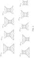
- the prosthetic heart valvecan be selected to have various inflow and outflow end lengths and shapes, as appropriate, to suit the particular characteristics of the anatomy. See, for example, FIG. 2 , which illustrates a stented prosthetic heart valve 20a, which is adequately configured and implanted within the particular pulmonary trunk 10. See also, FIG. 3 , which illustrates additional non-limiting examples of other prosthetic heart valves 20b-j having different configurations suitable for different anatomical variations.
- stented prosthesesmay assume a wide variety of configurations.
- Stented prosthesescan include, for example, stented prosthetic heart valves ("prosthetic valves"), such as a bioprosthetic heart valve having tissue leaflets or a synthetic heart valve having polymeric, metallic or tissue-engineered leaflets, and can be specifically configured for replacing valves of the human heart.
- prosthetic valvessuch as a bioprosthetic heart valve having tissue leaflets or a synthetic heart valve having polymeric, metallic or tissue-engineered leaflets, and can be specifically configured for replacing valves of the human heart.
- the stented prostheses of the present disclosuremay be self-expandable, balloon expandable and/or mechanically expandable or combinations thereof.
- the prosthetic valves of the present disclosureinclude a stent or stent frame having an internal lumen maintaining a valve structure (tissue or synthetic), with the stent frame having a normal, expanded condition or arrangement and collapsible to a compressed condition or arrangement for loading within a transcatheter prosthetic valve delivery device.
- the stents or stent framesare support structures that comprise a number of struts or wire segments arranged relative to each other to provide a desired compressibility and strength to the prosthetic valve.
- the struts or wire segmentsare arranged such that they are capable of self-transitioning from, or being forced from, a compressed or collapsed arrangement to a normal, radially expanded arrangement.
- the struts or wire segmentscan be formed from a shape memory material, such as a nickel titanium alloy (e.g., nitinol).
- the stent framecan be laser-cut from a single piece of material, or can be assembled from a number of discrete components.
- FIGS. 4A-4BA schematic illustration of one sizing catheter device or "lumen sizing device” 30 that can be used to determine size and/or other shape parameters of a bodily lumen (e.g., the pulmonary trunk 10) is illustrated in FIGS. 4A-4B .
- the sizing catheter device 30is arranged and configured for transluminal access by well-known techniques for assessing a patient's vasculature from a femoral vein or artery, for example.
- the catheter assembly 30is configured to be tracked over a previously inserted guide wire (not shown) for delivery to the target site 10.
- the sizing catheter device 30includes a handle assembly 32 interconnected to a catheter assembly 34.
- the catheter assembly 34includes one or more catheters 36 supporting proximal and distal sizers 38, 40, which are spaced apart along a length of the one or more catheters 36.
- additional sizerscan be provided (e.g., five sizers, ten sizers or more).
- the most proximal and most distal sizers 38, 40are spaced approximately 5 to 100 mm apart.
- the most proximal and most distal sizers 38, 40are spaced about 25 to about 55 mm apart. The spacing between the most proximal and most distal sizers 38, 40 might correspond to the length of the prosthetic heart valve that is intended to be implanted.
- the sizers 38, 40are connected to the catheter assembly 34 with one or more flexible elongate members 42, 44 extending to and controlled via the handle assembly 32 or the like to deploy the respective sizer 38, 40 (flexible elongate members 42 are generally referenced, see, FIG. 4B ).
- Each sizer 38, 40is arranged and configured to determine dimensions of the bodily lumen 10 in which the sizer 38, 40 is inserted. Therefore, in some embodiments, each sizer 38, 40 includes a flexible ring 39, 41 on which one or more sensors 46, 48 (generally referenced in FIG. 4B ) positioned on or about the respective sizer 38, 40.
- the sizers 38, 40are further configured to determine the distance between the proximal and distal sizers 38, 40.
- the distance between the sizers 38, 40is adjustable via the handle assembly 32 so that the distance between the sizers 38, 40 is determinable or known based on a user selected distance.
- the distal sizercan be secured to a first catheter positioned within a second catheter (see also, FIGS. 7A-7D ) and the handle assembly can be configured to change the position of the first catheter with respect to the second catheter, thus adjusting the position of the distal sizer with respect to the proximal sizer.
- the sensors 46, 48can be configured to obtain information regarding properties and characteristics of the lumen 10 that can be useful in determining an appropriately sized prosthetic heart valve or other prosthesis.
- the sensors 46, 48can include multiple electrodes positioned around the respective ring 39, 41 that are configured to measure the impedance between electrodes to determine when the sizer 38, 40 is positioned against tissue defining the lumen 10. For example, if the ring 39, 41 has a diameter such that it is surrounded by blood flow and not against tissue defining the lumen 10, an impedance measurement obtained by the electrodes may be low and when the electrodes of the sizer 38, 40 are in firm contact with tissue defining the lumen 10, the impedance measurement obtained by the electrodes may be higher.
- the diameter of the ring 39, 41can be expanded until the ring 39, 41 is against tissue defining the lumen 10, thus indicating a diameter of the lumen 10 at that location.
- the sensors 46, 48can also be configured to provide position-indicating information to assist a mapping process for determining the topography of the lumen 10.
- the sensors 46, 48can include piezoelectric sensors, optical sensors, electromagnetic sensors, capacitive sensors and the like. The disclosed embodiments are not intended to be limited to the use of any particular sensor as there are many types of sensors that can suitably obtain useful information regarding a lumen.
- the handle assembly 32can be of a variety of configurations suitable for directing the catheter assembly 34 through a bodily lumen, such as through a femoral vein to a pulmonary artery or the like.
- the handle assembly 32can further be configured to transition the sizers 38, 40 from a delivery position ( FIG. 4A ) in which the rings 39, 41 are compressed or unexpanded for ease of delivery, into a deployed position ( FIG. 4B ), in which the rings 39, 41 are expanded to contact tissue of the lumen to be sized.
- a first control 60is configured and arranged to adjust and indicate the expansion or perimeter of the distal ring 41
- a second control 62is configured and arranged to adjust and indicate the distance between the proximal and distal sizer 38, 40
- a third control 64is configured and arranged to indicate and adjust the expansion or perimeter of the proximal ring 39.
- the controls 60-64may be configured to be actuated by advancing the respective control 60-64 with respect to a body 66 of the handle assembly 32. In this way, all controls 60-64 can be operated independently of one another.
- the handle assembly 32can include one or more ports 68 interconnected for the injection of contrast material and/or for connection to one or more inflation sources (not shown) to inflate a temporary valve, the sizer 38 and/or the sizer 40 as will be discussed in detail below.
- the sizing catheter 30can further include a temporary prosthetic valve 70 (schematically shown).
- the temporary prosthetic valve 70is positioned on the catheter assembly 34 between the proximal and distal sizers 38, 40.
- either the proximal sizer or the distal sizer 38, 40can include a valve structure including valve leaflets (similar or identical to the structure of 70 shown in greater detail in FIGS. 5A -5D) so that when in the deployed, expanded position, the respective sizer 38, 40 functions also as a temporary prosthetic valve. In this way, the valve structure would be provided within one respecting ring 39, 41.
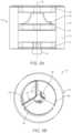
- the temporary prosthetic valve 70can be of the configuration shown in FIGS. 5A -5D.
- the temporary prosthetic valve 70 of this embodimentincludes a cylindrical wall 72 defining a hollow core 73.
- the wall 72can be inflated with fluid or gas via one or more inflation ports 74 that can be fluidly connected to the inflation source (not shown) via the port 68 of the handle assembly 32.
- the port 68can be connected to a conduit (not shown) that is routed within the catheter assembly 34, which extends to the port 68 of the handle assembly 32 for connection to the inflation source via the port 68.
- the temporary prosthetic valve 70includes three hollow supports 76 fluidly connected with and extending between the cylindrical wall 72.
- the temporary prosthetic valve 70includes three supports 76 with one support 76 positioned at each end of the temporary prosthetic valve 70 and one support 76 positioned near a middle of the temporary prosthetic valve 70.
- Each support 76includes three inflation channels 78 evenly spaced 120 degrees from each other that extend radially from the cylindrical wall 72 to a center axis 75 of the cylindrical wall 72 where the three inflation channels 78 intersect. This arrangement, although not required, provides generally even inflation of the cylindrical wall 72.
- the cylindrical wall 72further supports a valve structure 80 having leaflets 82, which become functional once the cylindrical wall 72 is at least partially inflated (e.g., about 60% or more inflated).
- the inflation channels 78are configured as to not substantially obstruct blood from through the temporary prosthetic valve 70.
- the inflation channels 78can further be configured to provide the leaflets 82 with backward flow resistance.
- one support 76can be positioned proximate the leaflets 82 as is best shown in FIG. 5A .
- the leaflets 82can be made via dip coating, extrusion or the like and the valve structure 80 can be attached to the cylindrical wall 72 with heat or glue bonding, for example.
- proximal and distal sizers 38, 40can take a variety of configurations suitable for determining properties of the lumen 10.
- a sizer 38'can include a ring 39' being an expandable mesh case made of nitinol or other suitable material.
- the sizer 38'can be actuated and include one or more sensors (not shown) in the same way as disclosed with respect to the sizers 38, 40.
- the sizersmay be inflatable.
- each sizercan be a balloon and can include a valve structure including valve leaflets, substantially similar to the temporary prosthetic valve 70, which can be delivered in a deflated, unexpanded position and then inflated via the port 68 of the handle assembly 32 to expand against the respective tissue at a target site.
- the inflationcan be set, for example, to mirror the force that would be applied by a prosthetic heart valve.
- the sizersdiffer in size but are otherwise similarly configured.
- the sizersdiffer both in size and configuration.
- the sizers and ringscan be mechanically actuated devices, such as a ring or a hoop having a diameter that is adjustable.
- the sizersare configured as to generally not obstruct blood flow if the sizers are positioned in a vascular lumen such as an artery or vein, for example.
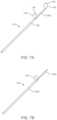
- the catheter assembly 134includes first and second catheters 136a-b as well as proximal and distal sizers 138, 140.
- the first and second catheters 136a-bare coaxially aligned and sized such that the second catheter 136b is smaller than and fits within the first catheter 136a. In this way, the distance between the proximal and distal sizers 138, 140 can be varied by adjusting the position of the second catheter 136b with respect to the first catheter 136a.
- each sizer 138, 140has both a delivery and a deployed position.
- the delivery positiongenerally corresponds with delivery of the sizers 138, 140 through the vasculature and the deployed position generally corresponds with the process of obtaining information regarding the lumen of interest.
- the respective sizer 138, 140is positioned within one or more catheters 136a-b.
- the respective sizer 138, 140extends radially outward from at least one of the catheters 136a-b.
- Each of the sizers 138, 140may include one or more sensors 146, 148 (schematically shown in FIG.
- the sensors 146, 148can be of any of the type disclosed herein and can be evenly spaced around the periphery of the sizer 138, 140 and/or can be provided in a matrix around the sizer 138, 140, as desired.
- FIG. 7Aillustrates the catheter assembly 134 in a delivery position.
- FIG. 7Billustrates a proximal sizer 138 of the catheter assembly 134 partially deployed (expanded) and extending radially from the first and second catheters 136a-b at a terminal end of the first catheter 136a.
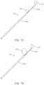
- FIG. 7Cillustrates the catheter assembly 134 with the proximal sizer 138 partially deployed and the distal sizer 140 extending radially from a distal end of the second catheter 136b and partially deployed (expanded).
- FIG. 7Dillustrates the catheter assembly 134 with the proximal sizer 138 fully deployed (expanded) and the distal sizer 140 partially deployed.
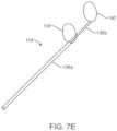
- FIG. 7Eillustrates both sizers 138, 140 being fully deployed.
- Additional aspects of the disclosureinclude methods and software for: 1) automatic patient screening; and/or 2) pre-operative planning of a stented prosthesis ("device") such as any of those disclosed above.
- the method of FIG. 8begins by obtaining pre-operative images of the anatomy (e.g., a pulmonary artery) in which the stented prosthesis is to be implanted.
- the imagescan be obtained from a computed tomography (CT) scan and/or a magnetic resonance (MR) scan or the like, for example.
- CTcomputed tomography
- MRmagnetic resonance
- the imagesare uploaded or otherwise made accessible to a computer operating the software. From that step, the images are collectively auto-segmented using machine-learning (e.g. convolutional neural networks (CNNs)).
- CNNsconvolutional neural networks
- the imagesare automatically segmented using machine-learning techniques (e.g., more specifically deep learning using multiple CNNs).
- This processoutputs 3D segmented volume that is divided into different anatomical structures of interest within the imaging volume (e.g., device landing zone, anatomical structures and landmarks).
- the CNNsare trained for voxel-wise labeling of cardiac images into structures such as right and left atriums and ventricles as well as ascending aorta and main pulmonary artery.
- bounding boxesare positioned around a target zone of the image. Automatic threshold calculation to identify the anatomy of interest from the background and segmentation of the target zone are conducted in any known manner to achieved desired contrast.
- manual supervision of any or all of the software decisionsis used to confirm accuracy.
- the physical measurementscan be inputted into the software as an alternative to, or in addition to, uploading images for modeling and device fit testing.
- the softwareconducts automatic virtual device geometrical fit testing.
- the softwareconducts an automatic interactive device-based analysis performing device-versus-anatomy geometrical comparison at different device landing scenarios (e.g., variety of device landing zone locations and/or axis orientations). This provides evaluation of factors such as oversizing, gap and fit of one or more devices with respect to the modeled patient anatomy.
- the softwareis configured to evaluate a plurality of devices for device position and, also, vectors (i.e. device axis angle).
- the softwarebegins with a three-dimensional image (i.e. the segmented model) of the patient anatomy.
- the softwareautomatically identifies/generates a centerline within an interior of the modeled anatomy. Then, with additional reference to FIG. 9C , the software optionally dilates the centerline.
- the ratio of dilationis selected with respect to the anatomical size and uncertainty of the centerline calculation.
- the centerlinecan be optionally dilated to about 10% of the maximum anatomical lateral size. However, the ratio of dilation may be less or greater, as desired.
- the softwareidentifies landing zone or deployment positions of the device upon implantation. This step is conducted using the following data: (1) the geometry of the device (e.g., length DL as shown in FIG. 10 ); (2) previously identified anatomy landmarks/structures; and (3) the restriction criteria on landing zone, possibly obtained from device instructions for use, (such instructions can include, for example, that the device should not stick into the right ventricle for pulmonary heart valve replacement, the device should not go deeper than a certain length below the annulus for aortic valve replacement (e.g., to prevent the possibility of heart block), the device should not go as high as covering the entire sinuses for aortic valve replacement (e.g., to prevent the possibility of coronary obstruction)).
- the geometry of the devicee.g., length DL as shown in FIG. 10
- the restriction criteria on landing zonepossibly obtained from device instructions for use, (such instructions can include, for example, that the device should not stick into the right ventricle for pulmonary heart valve replacement, the device should not go deeper than a certain length
- Aortic Position Condition 1( ⁇ L1 + ⁇ r1 ⁇ DL) and Aortic Position Condition 2 (L2 ⁇ ⁇ r2) of FIG. 10 .
- These potential considerationsprovide limitations for the software to filter out acceptable position coordinate candidates ("candidate points") from the dilated centerline points CL.
- the present disclosureis not intended to be limited to any particular combination of considerations.
- One example of this process and methodis outlined for both aortic and pulmonic portions of the anatomy in FIG 10 .
- the softwareadditionally establishes a range of device axis options.
- the range of device axis optionsis calculated by the software from the centerline, a curved centerline experiences a range of tangential vectors (orientation vectors) along its curvature.
- the softwarecalculates those, and adds a margin (e.g. ⁇ 5-10 degrees in 3D) to minimize the effect of centerline calculation uncertainty.
- the softwarealso, optionally provides a manual user interface environment for landing zone evaluations. More specifically, through a graphic user interface (GUI) the user could overlay the device on anatomy in 3D at several desired implant scenarios (locations and axes). The software, then, provides device-based fit score and fit analysis (e.g. perimeter profile of the device versus that of the anatomy) for those manual implanting inputs.
- GUIgraphic user interface
- the softwareis programmed to iteratively compare the implant scenarios for each, or at least a plurality of, potential devices.
- Each "perimeter" P(A) and P(D)represents a maximum width of the anatomy/device at particular locations along a length of the device DL or anatomy, as can generally be seen in FIG. 1 1(a) .
- S j at distal and proximal sealing levelscan be programmed to be assigned as follows.
- the fit score FSis greater than or equal to 2
- the softwaredetermines that the device is not suitable for the patient. If the fit score FS is equal to 3, the device is a candidate and will be analyzed by a biomechanical interaction module of the software.
- FIGS. 11(a)-11(b)are ranked (i.e. compared) to identify one or more of the top scoring (i.e. best) candidates for implant, device position and corresponding device axis. As shown in FIG. 11(b) for purposes of illustration, FS x is compared to FS y . It will be understood, however, that there is no intended limit to the number of fit scores that can be compared and ranked. In various embodiments, the top scoring candidates will all be analyzed by a biomechanical interaction module of the software.
- the biomechanical interaction moduleis programmed to predict and evaluate the biomechanical interaction between the device and the host anatomy.
- One main purpose of biomechanical interaction analysisincludes providing insights into the interaction between device and specific patient anatomy - preoperatively. Such insights are believed to have tremendous power to accelerate research and development of novel valve-based solutions, as well as ultimately improve clinical outcomes in real-world hospital settings.
- another purposeis to more accurately predict the oversizing, optimal landing zone, with respect to migration, paravalvular leakage, etc.
- biomechanical interactionis performed through bench testing or computational modeling (e.g. finite element analysis (FEA)). These methods require validation on how well they replicate the real situations. For example, the computational modeling is, specifically, computationally expensive and time consuming.. These approaches require user mechanical experimental or modeling expertise, accurate material properties and boundary condition evaluations.
- FEAfinite element analysis
- Biomechanical interaction between an implantable device and patient anatomyis predicted in the present embodiments through a data-driven predictor model of the biomechanical interaction module.
- the modelis a supervised machine learning model that is developed using pre- and post- implant data, provide post implant shape and performance through a real time biomechanical interaction predictor.
- a devicefrequently has one shape pre-implantation (shown on left) that differs substantially from a shape of the device once implanted (shown implanted in a translucent vessel on right) due to competing force exertions between the device and the host vessel anatomy.
- the biomechanical interaction moduleis configured to anticipate, or at the very least estimate, the interaction between devices and the host anatomy to inform the physician on oversizing, implanted landing zone, possible paravalvular leakage and so on. This provides important information to avoid improper oversizing, potential migration, and valve leakage and selecting a device that is too long or otherwise in appropriately configured for the particular anatomy upon implantation.
- D i and A irepresent device and anatomy geometrical parameters/factors/identifiers (including, but not limited to, cross-sectional maximum and minimum diameters, cross-sectional perimeter derive diameter, cross-sectional area, curvature, cross-sectional ellipticity, and etc.), at device i respectively.
- D* i and A* irepresent the corresponding post-implant pairs.
- the device and anatomy geometriesare parameterized into defining parameters for landing zone candidates (estimated in the last step ( FIG. 13(a) ).
- the defining parametersare characterized at several levels along a length of the device ( FIG. 13(a) ), and include factors (such as cross-sectional maximum and minimum diameters, cross-sectional perimeter derive diameter, cross-sectional area, curvature, cross-sectional ellipticity, and etc.) that are measured for anatomy on device based planes of a landing zone candidate for critical phases, or all phases, of the cardiac cycle (e.g. systole and diastole, this depends on device instructions for use and characterization/screening protocol).
- the transfer function, h( FIG. 13(b) ), (or as called in machine learning: hypothesis) then predicts corresponding parameters of post-implant space.
- the biomechanical interaction predictive modeli.e. h
- the biomechanical interaction predictive modelis formed from using a supervised machine learning approach or technique trained with existing datasets that include both pre- and post- implant. Specifically, the parameterized pre- and post- implant datasets are used for training the algorithm.
- the trained modelis capable of mapping the pre-implant parameters of a new patient to those of the post-implant. Modeling begins with identifying anatomy and device geometrical parameters at various points/levels along a length of the device, and slightly beyond it (e.g., 10% of device length on both proximal and distal ends of the device), to be implanted ( FIG. 13(a) ). At this stage, i.e. FIG.
- FIG. 13(b) "pre-implant"illustrates an example of how both the device and the modeled anatomy are predicted to generally look given biomechanical interaction between the device and the anatomy (i.e. D* 1 -D* n ; A* 1 -A* n ).
- FEAcan be implemented for each patient.
- machine learningcan be incorporated using existing pre versus post implant CT/MR imaging data that is collected and entered into the software.
- the computational modeling and experimentationse.g. FEA, animal model, cadaver studies, and bench testing
- FEAis used to extend pre to post prediction to those in which only pre-implantation data is available.
- the number of cases to span the space when FEA is used to extend pre to post implantation prediction to those with only pre-implantation dataare selected to represent the patient population, e.g. both extreme and average geometrical features that could be identified using geometrical model analysis (e.g., statistical shape modeling "SSM”). modal analysis (e.g., statistical shape modeling "SSM”).
- the training dataset, representing the target populationcould include one or both of the following categories: (1) in-vivo/in-vitro measurements (pre and post implant CT/MR images); and (2) computationally modeled cases (on both patient-specific anatomies, or virtually generated anatomies).
- the implant scenariosare scored and ranked.
- the softwarethen outputs recommendations on, device (model/size) as well as a suggested optimal position or zone for implantation including an implant position and device axis orientation. As desired and based on the results of the analysis conducted by the software, more than one device may be recommended.
- the softwareprovides assessments on post-implant risks (e.g. paravalvular leak (PVL), structural failure, device migration and etc.) through biomechanical predictive model.
- PVLparavalvular leak
- one embodiment of the present disclosureincludes a method of deploying a prosthesis or device (e.g., a heart valve prosthesis) within a lumen of a patient's anatomy (e.g., a pulmonary artery).
- the methodcomprises the delivery of a distal portion of a lumen sizing catheter device, such as any of those disclosed above, to a target site within the lumen.
- the lumen sizing catheter deviceincludes a handle assembly, a catheter extending from the handle assembly, a distal portion comprising a distal sizer positioned on the catheter proximal a distal end of the catheter, and a proximal sizer positioned on the catheter and spaced proximally from the distal sizer.
- the proximal and distal sizersare delivered to the target site within the lumen.
- the proximal and distal sizersare used to determine a first lumen dimension proximate the distal sizer and a second lumen dimension proximate the proximal sizer. In addition, the distance between the distal and proximal sizers is determined.
- a three-dimensional model of the target site of the lumenis used to create a three-dimensional model of the target site of the lumen as also described above. Based on the three-dimensional model, a plurality of potential prosthesis deployment positions and axis orientations relative to the lumen is determined. A geometric fit analysis is then performed by iteratively comparing the geometry of a plurality of differently sized prostheses to the plurality of potential prosthesis deployment positions and axis orientations to thereby identify one or more appropriately sized prostheses based on one or more geometric fit parameters (as discussed above).
- a biomechanical interaction analysisis then performed in the manner disclosed above between the one or more appropriately sized prostheses and the patient's anatomy to select a properly sized prosthesis for implantation within the lumen.
- the properly sized prosthesisis then implanted or deployed within the lumen.
- the proximal sizeris adjustably spaced from the distal sizer (e.g., see the embodiment of FIGS. 7A-7E and related disclosure).
- the distal and proximal sizersare configured to determine first and second dimensions of the lumen at a selected distance between the distal and proximal sizers (e.g., see the embodiment of FIGS. 7A-7E and related disclosure).
- the distal and/or proximal sizersinclude a hoop having an adjustable diameter (e.g., see the embodiment of FIGS. 7A-7E and related disclosure).
- the distal sizer and the proximal sizerare different sizes (e.g., see the embodiments of FIGS. 4B and 7D and related disclosure).
- the distal sizeris spaced from the proximal sizer between about 5 and about 100 mm.
- the distal and/or proximal sizersare inflatable.
- the distal and/or proximal sizersare adjustable in diameter via the handle assembly (e.g., see the embodiments of FIGS.
- the distance between the sizersis adjustable independent of adjustment of a diameter of the proximal or distal sizer (e.g., see the embodiments of FIGS. 4A and 7A and related disclosure).
- the distal and/or proximal sizersinclude a valve structure as discussed above.
- the distal and proximal sizersinclude a lumen to allow for blood flow through the distal and proximal sizers (e.g., see the embodiments of FIGS. 4A and 7A and related disclosure).
- the lumen sizing catheter devicefurther comprises a prosthetic valve positioned on the catheter between the distal sizer and the proximal sizer as discussed above.
- at least one of the proximal and distal sizersincludes a sensor selected from the group consisting of a mechanical sensor and an impedance sensor.
- the proximal sizeris adjustably spaced from the distal sizer as described above.
- CT or MR imaging data of a portion of the patient's anatomy including the lumencan be used to create or help create a three-dimensional model of the patient's anatomy including the lumen.
- the three-dimensional model of the target site of the lumenincludes the use of images from one or more imaging techniques of the patient's anatomy as described above.
- one or more data-driven machine learning techniquescan be used in one or more analyses as described above with respect to FIGS. 8-13(b) .
- FEAcan be used in one or more analyses as disclosed with respect to FIGS. 8-13(b) .
- statistical shape modelingcan be used in one or more analyses as disclosed with respect to FIGS. 8-13(b) .
- an optimal prosthesis or device deployment position and axis orientation within the lumenis determined as described above.
- a prosthesisis selected for implantation or deployment within the lumen in an optimal position and axis orientation as determined by one or more analyses described above with respect to FIGS. 8-13(b) .
Landscapes
- Health & Medical Sciences (AREA)
- Life Sciences & Earth Sciences (AREA)
- Heart & Thoracic Surgery (AREA)
- Veterinary Medicine (AREA)
- Public Health (AREA)
- General Health & Medical Sciences (AREA)
- Animal Behavior & Ethology (AREA)
- Engineering & Computer Science (AREA)
- Biomedical Technology (AREA)
- Biophysics (AREA)
- Medical Informatics (AREA)
- Molecular Biology (AREA)
- Surgery (AREA)
- Pathology (AREA)
- Physics & Mathematics (AREA)
- Cardiology (AREA)
- Oral & Maxillofacial Surgery (AREA)
- Transplantation (AREA)
- Vascular Medicine (AREA)
- Dentistry (AREA)
- Prostheses (AREA)
Description
- This Non-Provisional Patent Application claims the benefit of the filing date of
U.S. Provisional Patent Application Serial Number 62/481,853, filed April 5, 2017 - The present disclosure relates to sizing catheters for determining the size and other physical parameters of an internal orifice or lumen, such as an artery, vein, pulmonary trunk or aorta, to provide a physician with information relating to size and/or other parameters of the internal lumen for use in selecting an appropriate prosthetic device, such as a prosthetic heart valve.
- It is important to select an appropriately configured prosthetic heart valve because if the prosthetic heart valve does not fit properly, the prosthetic heart valve may migrate, leak or cause other problems. In order to select an appropriately sized prosthetic heart valve, the size, shape, topography, compliance and other physical parameters of a vessel lumen are often assessed. In some circumstances, an exhaustive image collection and image measurements are required to be analyzed for selecting a stented prosthetic heart valve configured to fit a patient's particular anatomy. Obtaining such images via a magnetic resonance angiogram (MRA) or computed tomography (CT scan) or the like requires a substantial amount of time and expense.
- Various devices are also available for internally determining the size and other physical parameters of an internal orifice or lumen. Such devices can include an expandable member, such as a balloon, capable of expanding to contact tissue and collect information relating to physical parameters of the tissue proximate the expandable member.
- Relevant prior art is disclosed in
US 2013/123694 . - The present disclosure addresses problems and limitations associated with the related art.
- As indicated above, it is important to select an appropriately configured prosthetic heart valve because if the prosthetic heart valve does not fit properly, it may migrate, leak or cause other problems. In order to select an appropriately sized prosthetic heart valve, the size, shape, topography, compliance and other physical parameters of a vessel lumen are assessed. Certain expandable members, such as balloons, used for conducting such an assessment of a patient's anatomy have their drawbacks. For example, it has been observed by the present inventors that balloons, for example, straighten out and deform to the anatomy as they are expanded. An additional drawback is that balloons block the flow of blood, which can cause patients distress and can alter physiologic function, which provides inaccurate results. Aspects of the disclosure address these limitations. According to the present invention there is provided a sizing catheter as set out in the appended claims.
- Certain disclosed embodiments include a sizing catheter assembly having a handle assembly and a catheter assembly extending from the handle assembly. The sizing catheter is arranged and configured for transluminal access by well-known techniques for assessing a patient's vasculature from an artery or vein, for example. The catheter assembly includes at least one catheter as well as a distal sizer positioned on a distal end of the catheter and a proximal sizer positioned on the catheter and adjustably spaced from the distal sizer. Each of the distal and proximal sizers are configured to deploy to conform to respective portions of a lumen of a patient's anatomy, such as a pulmonary trunk, for example. The sizing catheter is configured to determine first and second dimensions of the lumen at a selected distance between the distal and proximal sizers. The proximal and distal sizers can take a variety of forms. Optionally, one or more of the proximal and distal sizers can include a valve structure. Moreover, the sizing catheter can optionally include a temporary prosthetic valve positioned on the catheter.
- Aspects of the disclosure not covered by the present invention also include methods of sizing a lumen of a patient's anatomy for selecting an appropriately sized prosthesis. Methods can include providing a sizing catheter, delivering the sizing catheter to a target site within the lumen; and determining dimensions of the lumen with the distal and proximal sizers including a diameter of the lumen proximate the distal and proximal sizers and also determining a distance between the distal and proximal sizers. Based on information obtained from the sizing catheter, the method can include selecting a prosthetic valve based on the sensed or measured dimensions and/or other sensed or measured lumen properties. Once the appropriate prosthetic valve is selected, the prosthetic valve can be delivered and deployed with an appropriate delivery device.
- Additional aspects of the disclosure not covered by the present invention include methods and software for: 1) automatic patient screening; and/or 2) pre-operative planning of a stented prosthesis. In such methods, images of the anatomy and/or anatomy size measurements are made available or otherwise inputted to the software for modeling and automatic virtual device fit testing of one or more potential prosthetic devices. Anatomy size measurements can be obtained with any of the disclosed sizing catheter assemblies, for example. In various embodiments, the software includes a biomechanical interaction module that is programmed to predict and evaluate the biomechanical interaction between the device and the host anatomy.
- Although much of the present disclosure is in relation to applications directed toward heart valve assessment. It will be understood, in view of the disclosure, that the disclosed embodiments can be adapted and applied for use in other vessel lumens and orifices of the human body.
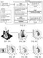
FIG. 1A is an antero-posterior/cranial view of a pulmonary trunk.FIG. 1B is a left lateral view of the pulmonary trunk ofFIG. 1A .FIG. 2 is a partially transparent view of a stented prosthesis deployed within the pulmonary trunk ofFIGS. 1A-1B .FIG. 3 schematically illustrates a plurality of stented prostheses having a variety of configurations.FIG. 4A is a schematic illustration of a sizing catheter having a proximal sizer, distal sizer and temporary valve in a delivery configuration positioned within the pulmonary trunk.FIG. 4B is a schematic illustration of the sizing catheter ofFIG. 4A ; wherein the proximal sizer, the distal sizer and the temporary valve are in a deployed configuration positioned within the pulmonary trunk.FIG. 5A is a partially transparent side view of the temporary valve ofFIGS. 4A-4B .FIG. 5B is a partial, top view of the temporary valve ofFIG. 5A .FIG. 5C is a partially transparent side view of the temporary valve ofFIGS. 5A-5B .FIG. 6 is a perspective view of an alternate sizer that can be used with the sizing catheter ofFIGS. 4A-4B .FIG. 7A is a perspective view of an alternate catheter assembly in a delivery configuration that can be used with the sizing catheter ofFIGS. 4A-4B .FIG. 7B is a perspective view of the catheter assembly ofFIG. 7A in which a proximal sizer is deployed to a first position.FIG. 7C is a perspective view of the catheter assembly ofFIGS. 7A-7B in which a distal sizer is further deployed to a first position.FIG. 7D is a perspective view of the catheter assembly ofFIGS. 7A-7C in which the proximal sizer is deployed to a second position.FIG. 7E is a perspective view of the catheter assembly ofFIGS. 7A-7D in which the distal sizer is also deployed to a second position.FIG. 8 is a flow diagram of one method of the disclosure.FIG. 9A is a representative example of a 3D image of a patient's anatomy.FIG. 9B illustrates an auto-segmented image ofFIG. 9A .FIG. 9C illustrates the anatomy and a centerline plotted in the auto-segmented image ofFIG. 9B .FIG. 9D illustrates the anatomy and centerline ofFIG. 9C having been dilated.FIG. 9E illustrates a range of prosthesis ("device") positions.FIG. 9F illustrates a range of device axis orientations.FIG. 10 illustrates various position conditions with respect to the device and anatomy.FIGS. 11(a)-11(b) illustrate a determination of fit scores.FIG. 12 illustrates an example of one device both pre and post implantation within a patient's anatomy (shown as translucent for clarity).FIGS. 13(a)-13(b) schematically illustrate pre and post implant configurations of both the device and the anatomy, which are predicted and modeled with the software and method ofFIG. 8 .- Specific embodiments of the present disclosure are now described with reference to the figures, wherein like reference numbers indicate identical or functionally similar elements. The terms "distal" and "proximal" are used in the following description with respect to a position or direction relative to the treating clinician. "Distal" or "distally" are a position distant from or in a direction away from the clinician. "Proximal" and "proximally" are a position near or in a direction toward the clinician.
- The sizing of a bodily orifice in which a prosthetic device (e.g., a transcatheter prosthetic heart valve) is to be implanted is typically desired. A properly sized prosthetic heart valve is important to prevent migration of the prosthetic heart valve or embolization, prevent paravalvular leakage, prevent excessive hemodynamic loads from poor apposition, prevent compression on leaflets of the prosthetic heart valve and also to prevent tissue erosion, for example. Some sizing procedure embodiments require a collection of images and/or image measurements to determine an appropriate prosthetic heart valve suitable to fit the patient's anatomy.
FIGS. 1A-1B include example images of apulmonary trunk 10 and illustrate various measurements that can be obtained to assess useful physical parameters of the anatomy. For example, useful measurements can include cross-sectional measurements such as diameter or perimeter at a sub-valve A, supra-valve B, pre-bifurcation C, mid-valve D between A and B, mid-trunk E between B and C and also at the right ventricular outflow tract RVOT, for example. In addition, obtaining length measurements can also be beneficial including an overall MPA length C-RVOT, sub-valve A to supra valve length B and supra-valve B to pre-bifurcation length C, for example. - After obtaining measurements regarding parameters of the anatomy of interest, an appropriate prosthetic heart valve can be selected such that the prosthetic heart valve provides adequate outward force, stability and sealing when implanted. In addition, the prosthetic heart valve can be selected to have various inflow and outflow end lengths and shapes, as appropriate, to suit the particular characteristics of the anatomy. See, for example,
FIG. 2 , which illustrates a stentedprosthetic heart valve 20a, which is adequately configured and implanted within the particularpulmonary trunk 10. See also,FIG. 3 , which illustrates additional non-limiting examples of otherprosthetic heart valves 20b-j having different configurations suitable for different anatomical variations. - As indicated herein, stented prostheses may assume a wide variety of configurations. Stented prostheses can include, for example, stented prosthetic heart valves ("prosthetic valves"), such as a bioprosthetic heart valve having tissue leaflets or a synthetic heart valve having polymeric, metallic or tissue-engineered leaflets, and can be specifically configured for replacing valves of the human heart. The stented prostheses of the present disclosure may be self-expandable, balloon expandable and/or mechanically expandable or combinations thereof. In general terms, the prosthetic valves of the present disclosure include a stent or stent frame having an internal lumen maintaining a valve structure (tissue or synthetic), with the stent frame having a normal, expanded condition or arrangement and collapsible to a compressed condition or arrangement for loading within a transcatheter prosthetic valve delivery device. For example, the stents or stent frames are support structures that comprise a number of struts or wire segments arranged relative to each other to provide a desired compressibility and strength to the prosthetic valve. The struts or wire segments are arranged such that they are capable of self-transitioning from, or being forced from, a compressed or collapsed arrangement to a normal, radially expanded arrangement. The struts or wire segments can be formed from a shape memory material, such as a nickel titanium alloy (e.g., nitinol). The stent frame can be laser-cut from a single piece of material, or can be assembled from a number of discrete components.
- A schematic illustration of one sizing catheter device or "lumen sizing device" 30 that can be used to determine size and/or other shape parameters of a bodily lumen (e.g., the pulmonary trunk 10) is illustrated in
FIGS. 4A-4B . The sizingcatheter device 30 is arranged and configured for transluminal access by well-known techniques for assessing a patient's vasculature from a femoral vein or artery, for example. In one embodiment, thecatheter assembly 30 is configured to be tracked over a previously inserted guide wire (not shown) for delivery to thetarget site 10. The sizingcatheter device 30 includes ahandle assembly 32 interconnected to acatheter assembly 34. Thecatheter assembly 34 includes one ormore catheters 36 supporting proximal anddistal sizers more catheters 36. In alternate embodiments, additional sizers can be provided (e.g., five sizers, ten sizers or more). In some embodiments, the most proximal and mostdistal sizers distal sizers distal sizers sizers catheter assembly 34 with one or more flexibleelongate members handle assembly 32 or the like to deploy therespective sizer 38, 40 (flexibleelongate members 42 are generally referenced, see,FIG. 4B ). Eachsizer bodily lumen 10 in which thesizer sizer flexible ring more sensors 46, 48 (generally referenced inFIG. 4B ) positioned on or about therespective sizer sizers distal sizers sizers handle assembly 32 so that the distance between thesizers FIGS. 7A-7D ) and the handle assembly can be configured to change the position of the first catheter with respect to the second catheter, thus adjusting the position of the distal sizer with respect to the proximal sizer. - The
sensors lumen 10 that can be useful in determining an appropriately sized prosthetic heart valve or other prosthesis. In one non-limiting example, thesensors respective ring sizer lumen 10. For example, if thering lumen 10, an impedance measurement obtained by the electrodes may be low and when the electrodes of thesizer lumen 10, the impedance measurement obtained by the electrodes may be higher. In this way, the diameter of thering ring lumen 10, thus indicating a diameter of thelumen 10 at that location. Thesensors lumen 10. In further example embodiments, thesensors - The
handle assembly 32 can be of a variety of configurations suitable for directing thecatheter assembly 34 through a bodily lumen, such as through a femoral vein to a pulmonary artery or the like. Thehandle assembly 32 can further be configured to transition thesizers FIG. 4A ) in which therings FIG. 4B ), in which therings first control 60 is configured and arranged to adjust and indicate the expansion or perimeter of thedistal ring 41, asecond control 62 is configured and arranged to adjust and indicate the distance between the proximal anddistal sizer third control 64 is configured and arranged to indicate and adjust the expansion or perimeter of theproximal ring 39. The controls 60-64 may be configured to be actuated by advancing the respective control 60-64 with respect to abody 66 of thehandle assembly 32. In this way, all controls 60-64 can be operated independently of one another. Thehandle assembly 32 can include one ormore ports 68 interconnected for the injection of contrast material and/or for connection to one or more inflation sources (not shown) to inflate a temporary valve, thesizer 38 and/or thesizer 40 as will be discussed in detail below. - Optionally, the sizing
catheter 30 can further include a temporary prosthetic valve 70 (schematically shown). In some embodiments, the temporaryprosthetic valve 70 is positioned on thecatheter assembly 34 between the proximal anddistal sizers distal sizer FIGS. 5A -5D) so that when in the deployed, expanded position, therespective sizer ring - If the optional temporary
prosthetic valve 70 is provided separate from thesizers prosthetic valve 70 can be of the configuration shown inFIGS. 5A -5D. The temporaryprosthetic valve 70 of this embodiment includes acylindrical wall 72 defining ahollow core 73. Thewall 72 can be inflated with fluid or gas via one ormore inflation ports 74 that can be fluidly connected to the inflation source (not shown) via theport 68 of thehandle assembly 32. For example, theport 68 can be connected to a conduit (not shown) that is routed within thecatheter assembly 34, which extends to theport 68 of thehandle assembly 32 for connection to the inflation source via theport 68. In this embodiment, the temporaryprosthetic valve 70 includes threehollow supports 76 fluidly connected with and extending between thecylindrical wall 72. In one embodiment, the temporaryprosthetic valve 70 includes threesupports 76 with onesupport 76 positioned at each end of the temporaryprosthetic valve 70 and onesupport 76 positioned near a middle of the temporaryprosthetic valve 70. Eachsupport 76 includes threeinflation channels 78 evenly spaced 120 degrees from each other that extend radially from thecylindrical wall 72 to acenter axis 75 of thecylindrical wall 72 where the threeinflation channels 78 intersect. This arrangement, although not required, provides generally even inflation of thecylindrical wall 72. Thecylindrical wall 72 further supports avalve structure 80 havingleaflets 82, which become functional once thecylindrical wall 72 is at least partially inflated (e.g., about 60% or more inflated). In other words, upon partial inflation of thecylindrical wall 72, the forward blood flow will push theleaflets 82 open and theleaflets 82 will proceed to function similar to a native heart valve for as long as thecylindrical wall 72 remains at least partially inflated. Theinflation channels 78 are configured as to not substantially obstruct blood from through the temporaryprosthetic valve 70. Theinflation channels 78 can further be configured to provide theleaflets 82 with backward flow resistance. For example, onesupport 76 can be positioned proximate theleaflets 82 as is best shown inFIG. 5A . Theleaflets 82 can be made via dip coating, extrusion or the like and thevalve structure 80 can be attached to thecylindrical wall 72 with heat or glue bonding, for example. - The proximal and
distal sizers lumen 10. In some embodiments, as shown inFIG. 6 , a sizer 38' can include a ring 39' being an expandable mesh case made of nitinol or other suitable material. The sizer 38' can be actuated and include one or more sensors (not shown) in the same way as disclosed with respect to thesizers prosthetic valve 70, which can be delivered in a deflated, unexpanded position and then inflated via theport 68 of thehandle assembly 32 to expand against the respective tissue at a target site. The inflation can be set, for example, to mirror the force that would be applied by a prosthetic heart valve. In some embodiments, the sizers differ in size but are otherwise similarly configured. In other embodiments, the sizers differ both in size and configuration. In other embodiments the sizers and rings can be mechanically actuated devices, such as a ring or a hoop having a diameter that is adjustable. In the disclosed embodiments, the sizers are configured as to generally not obstruct blood flow if the sizers are positioned in a vascular lumen such as an artery or vein, for example. - Referring now also to
FIGS. 7A-7E , which illustrate onealternate catheter assembly 134 that can be used with the disclosed sizing catheters, such as the sizingcatheter device 34 ofFIGS. 4A-4B . In this embodiment, thecatheter assembly 134 includes first andsecond catheters 136a-b as well as proximal anddistal sizers second catheters 136a-b are coaxially aligned and sized such that thesecond catheter 136b is smaller than and fits within thefirst catheter 136a. In this way, the distance between the proximal anddistal sizers second catheter 136b with respect to thefirst catheter 136a. In this embodiment, eachsizer sizers respective sizer more catheters 136a-b. In the deployed or at least partially-deployed position, therespective sizer catheters 136a-b. Each of thesizers more sensors 146, 148 (schematically shown inFIG. 7A ) coupled to or otherwise integrated within the hoop material of thesizer sensors sizer sizer FIG. 7A illustrates thecatheter assembly 134 in a delivery position.FIG. 7B illustrates aproximal sizer 138 of thecatheter assembly 134 partially deployed (expanded) and extending radially from the first andsecond catheters 136a-b at a terminal end of thefirst catheter 136a.FIG. 7C illustrates thecatheter assembly 134 with theproximal sizer 138 partially deployed and thedistal sizer 140 extending radially from a distal end of thesecond catheter 136b and partially deployed (expanded).FIG. 7D illustrates thecatheter assembly 134 with theproximal sizer 138 fully deployed (expanded) and thedistal sizer 140 partially deployed.FIG. 7E illustrates bothsizers - Additional aspects of the disclosure include methods and software for: 1) automatic patient screening; and/or 2) pre-operative planning of a stented prosthesis ("device") such as any of those disclosed above. Specifically, the method of
FIG. 8 begins by obtaining pre-operative images of the anatomy (e.g., a pulmonary artery) in which the stented prosthesis is to be implanted. The images can be obtained from a computed tomography (CT) scan and/or a magnetic resonance (MR) scan or the like, for example. The images are uploaded or otherwise made accessible to a computer operating the software. From that step, the images are collectively auto-segmented using machine-learning (e.g. convolutional neural networks (CNNs)). In this way, the images are automatically segmented using machine-learning techniques (e.g., more specifically deep learning using multiple CNNs). This process outputs 3D segmented volume that is divided into different anatomical structures of interest within the imaging volume (e.g., device landing zone, anatomical structures and landmarks). For example, the CNNs are trained for voxel-wise labeling of cardiac images into structures such as right and left atriums and ventricles as well as ascending aorta and main pulmonary artery. During the auto-segmentation process, bounding boxes are positioned around a target zone of the image. Automatic threshold calculation to identify the anatomy of interest from the background and segmentation of the target zone are conducted in any known manner to achieved desired contrast. In some methods, manual supervision of any or all of the software decisions (e.g., identification of landmarks) is used to confirm accuracy. Alternatively, if physical dimensions of the anatomical structure of interest are known because they were physically measured, for example, with one of the above-referenced devices or the like, the physical measurements can be inputted into the software as an alternative to, or in addition to, uploading images for modeling and device fit testing. - Next, the software conducts automatic virtual device geometrical fit testing. Particularly, the software conducts an automatic interactive device-based analysis performing device-versus-anatomy geometrical comparison at different device landing scenarios (e.g., variety of device landing zone locations and/or axis orientations). This provides evaluation of factors such as oversizing, gap and fit of one or more devices with respect to the modeled patient anatomy. The software is configured to evaluate a plurality of devices for device position and, also, vectors (i.e. device axis angle). In additional reference to
FIG. 9A , the software begins with a three-dimensional image (i.e. the segmented model) of the patient anatomy. With additional reference toFIG. 9B , the software automatically identifies/generates a centerline within an interior of the modeled anatomy. Then, with additional reference toFIG. 9C , the software optionally dilates the centerline. The ratio of dilation is selected with respect to the anatomical size and uncertainty of the centerline calculation. For example, the centerline can be optionally dilated to about 10% of the maximum anatomical lateral size. However, the ratio of dilation may be less or greater, as desired. - With additional reference to
FIGS. 9D and10 , the software identifies landing zone or deployment positions of the device upon implantation. This step is conducted using the following data: (1) the geometry of the device (e.g., length DL as shown inFIG. 10 ); (2) previously identified anatomy landmarks/structures; and (3) the restriction criteria on landing zone, possibly obtained from device instructions for use, (such instructions can include, for example, that the device should not stick into the right ventricle for pulmonary heart valve replacement, the device should not go deeper than a certain length below the annulus for aortic valve replacement (e.g., to prevent the possibility of heart block), the device should not go as high as covering the entire sinuses for aortic valve replacement (e.g., to prevent the possibility of coronary obstruction)). See for example, Aortic Position Condition 1 (ΔL1 +Δr1 ≤ DL) and Aortic Position Condition 2 (L2 ≥ Δr2) ofFIG. 10 . These potential considerations provide limitations for the software to filter out acceptable position coordinate candidates ("candidate points") from the dilated centerline points CL. The present disclosure is not intended to be limited to any particular combination of considerations. One example of this process and method is outlined for both aortic and pulmonic portions of the anatomy inFIG 10 . - With further reference to
FIGS. 9E-9F , the software additionally establishes a range of device axis options. The range of device axis options is calculated by the software from the centerline, a curved centerline experiences a range of tangential vectors (orientation vectors) along its curvature. The software calculates those, and adds a margin (e.g. ± 5-10 degrees in 3D) to minimize the effect of centerline calculation uncertainty. - It will be understood that the determinations made in
FIGS. 9A-9F can be made concurrently or sequentially in an order that differs from the order of the presented figures. Overall this aspect of the software: (1) takes in a 3D reconstructed geometry (segmented geometry) of the anatomical landing zone (e.g., main pulmonary artery from RVOT to bifurcation for pulmonic valve, from LVOT to arch of the aorta, ascending aorta, for an aortic valve); (2) calculates the centerline of the anatomy and dilates the centerline; (3) identifies the coordinates of location candidates (for a point of reference on the device, e.g. distal end) and device orientation; (4) scores each landing candidate point (a combination of device location and orientation) and comparatively identifies the best. The software, also, optionally provides a manual user interface environment for landing zone evaluations. More specifically, through a graphic user interface (GUI) the user could overlay the device on anatomy in 3D at several desired implant scenarios (locations and axes). The software, then, provides device-based fit score and fit analysis (e.g. perimeter profile of the device versus that of the anatomy) for those manual implanting inputs. - Once potential device landing or deployment positions and device axis orientations are determined, the software is programmed to iteratively compare the implant scenarios for each, or at least a plurality of, potential devices. By analyzing fit criteria as generally outlined in
FIG. 11(a) (e.g., perimeter difference, overlap area, geometrical gap and oversizing "OS" ratio (e.g.,
FIG. 1 1(a) . Each fit score FS for this illustrative embodiment is the addition of measured sealing levels/locations (e.g. Si = 1, 2, 3 representing regions of inflow, valve housing, and outflow) along the length of the device DL as virtually implanted. Sj at distal and proximal sealing levels can be programmed to be assigned as follows. Sj=1 if at least one OSi is greater than or equal offlow% ≤ OS ≤fhigh% (whereinf% is acceptable oversizing ratio, which is provided in instructions for use ("IFU")/implant protocol of the device use). This ratio should not be higher than certain level to avoid structural failure and should not be below a certain % to avoid risk of migration or paravalvular leakage). If not, Sj= -1. For levels of no compression (e.g. valve housing in prosthetic heart valves), Sj = 1 if OS ≤ff% (whereinff% is acceptable oversizing limit, which is provided in instructions for use ("IFU")/implant protocol of the device use) for all; else Sj = -1. In the case of a device with three critical levels (i.e. Sj = 1, 2, 3 representing regions of inflow, valve housing, and outflow), if the fit score FS is greater than or equal to 2, the software determines that the device is not suitable for the patient. If the fit score FS is equal to 3, the device is a candidate and will be analyzed by a biomechanical interaction module of the software. Once each implant scenario fit score FS is determined, the fit scores FSx,y,...n (n represent the number of implant scenarios)FIGS. 11(a)-11(b) are ranked (i.e. compared) to identify one or more of the top scoring (i.e. best) candidates for implant, device position and corresponding device axis. As shown inFIG. 11(b) for purposes of illustration, FSx is compared to FSy. It will be understood, however, that there is no intended limit to the number of fit scores that can be compared and ranked. In various embodiments, the top scoring candidates will all be analyzed by a biomechanical interaction module of the software. - The biomechanical interaction module is programmed to predict and evaluate the biomechanical interaction between the device and the host anatomy. One main purpose of biomechanical interaction analysis includes providing insights into the interaction between device and specific patient anatomy - preoperatively. Such insights are believed to have tremendous power to accelerate research and development of novel valve-based solutions, as well as ultimately improve clinical outcomes in real-world hospital settings. In addition, another purpose is to more accurately predict the oversizing, optimal landing zone, with respect to migration, paravalvular leakage, etc. Currently, biomechanical interaction is performed through bench testing or computational modeling (e.g. finite element analysis (FEA)). These methods require validation on how well they replicate the real situations. For example, the computational modeling is, specifically, computationally expensive and time consuming.. These approaches require user mechanical experimental or modeling expertise, accurate material properties and boundary condition evaluations.
- Biomechanical interaction between an implantable device and patient anatomy is predicted in the present embodiments through a data-driven predictor model of the biomechanical interaction module. The model is a supervised machine learning model that is developed using pre- and post- implant data, provide post implant shape and performance through a real time biomechanical interaction predictor. As is generally illustrated in
FIG. 12 , a device frequently has one shape pre-implantation (shown on left) that differs substantially from a shape of the device once implanted (shown implanted in a translucent vessel on right) due to competing force exertions between the device and the host vessel anatomy. The biomechanical interaction module is configured to anticipate, or at the very least estimate, the interaction between devices and the host anatomy to inform the physician on oversizing, implanted landing zone, possible paravalvular leakage and so on. This provides important information to avoid improper oversizing, potential migration, and valve leakage and selecting a device that is too long or otherwise in appropriately configured for the particular anatomy upon implantation. - Referring now also to
FIGS. 13(a)-13(b) , one model for predicting the biomechanical interaction between the device and the host anatomy (compliance and deformation) is summarized as follows: h (D,A↔D*,A*). Di and Ai represent device and anatomy geometrical parameters/factors/identifiers (including, but not limited to, cross-sectional maximum and minimum diameters, cross-sectional perimeter derive diameter, cross-sectional area, curvature, cross-sectional ellipticity, and etc.), at device i respectively. Notably, D*i and A*i represent the corresponding post-implant pairs. In this approach or technique: first the device and anatomy geometries are parameterized into defining parameters for landing zone candidates (estimated in the last step (FIG. 13(a) ). The defining parameters are characterized at several levels along a length of the device (FIG. 13(a) ), and include factors (such as cross-sectional maximum and minimum diameters, cross-sectional perimeter derive diameter, cross-sectional area, curvature, cross-sectional ellipticity, and etc.) that are measured for anatomy on device based planes of a landing zone candidate for critical phases, or all phases, of the cardiac cycle (e.g. systole and diastole, this depends on device instructions for use and characterization/screening protocol). The transfer function, h (FIG. 13(b) ), (or as called in machine learning: hypothesis) then predicts corresponding parameters of post-implant space. - The biomechanical interaction predictive model ,i.e. h, is formed from using a supervised machine learning approach or technique trained with existing datasets that include both pre- and post- implant. Specifically, the parameterized pre- and post- implant datasets are used for training the algorithm. The trained model, then, is capable of mapping the pre-implant parameters of a new patient to those of the post-implant. Modeling begins with identifying anatomy and device geometrical parameters at various points/levels along a length of the device, and slightly beyond it (e.g., 10% of device length on both proximal and distal ends of the device), to be implanted (
FIG. 13(a) ). At this stage, i.e.FIG. 13(b) "pre-implant", no account is made for the biomechanical interaction between the device and the anatomy. Therefore, it is likely that if the device is implanted in the modeled anatomy, the final result will not resemble what is illustrated.FIG. 13(b) "post-implant" illustrates an example of how both the device and the modeled anatomy are predicted to generally look given biomechanical interaction between the device and the anatomy (i.e. D*1-D*n; A*1-A*n). - Various models can be prepared for determining the biomechanical interaction between the implanted device and the anatomy (D'1-D'n; A*1-A*n). In one simplified example, FEA can be implemented for each patient. Alternatively, machine learning can be incorporated using existing pre versus post implant CT/MR imaging data that is collected and entered into the software. In this software, the computational modeling and experimentations (e.g. FEA, animal model, cadaver studies, and bench testing) are used to extend the number of dataset with both pre- and post-implant. For example, FEA is used to extend pre to post prediction to those in which only pre-implantation data is available. It is noted that the number of cases to span the space when FEA is used to extend pre to post implantation prediction to those with only pre-implantation data are selected to represent the patient population, e.g. both extreme and average geometrical features that could be identified using geometrical model analysis (e.g., statistical shape modeling "SSM"). modal analysis (e.g., statistical shape modeling "SSM"). Finally the training dataset, representing the target population, could include one or both of the following categories: (1) in-vivo/in-vitro measurements (pre and post implant CT/MR images); and (2) computationally modeled cases (on both patient-specific anatomies, or virtually generated anatomies).
- After modeling all implant scenarios post implantation (i.e. given the predicted biomechanical interaction using trained model, i.e.h) the implant scenarios are scored and ranked. The software then outputs recommendations on, device (model/size) as well as a suggested optimal position or zone for implantation including an implant position and device axis orientation. As desired and based on the results of the analysis conducted by the software, more than one device may be recommended. In addition, the software provides assessments on post-implant risks (e.g. paravalvular leak (PVL), structural failure, device migration and etc.) through biomechanical predictive model.
- In view of the above, one embodiment of the present disclosure includes a method of deploying a prosthesis or device (e.g., a heart valve prosthesis) within a lumen of a patient's anatomy (e.g., a pulmonary artery). The method comprises the delivery of a distal portion of a lumen sizing catheter device, such as any of those disclosed above, to a target site within the lumen. As described above with respect to various embodiments, the lumen sizing catheter device includes a handle assembly, a catheter extending from the handle assembly, a distal portion comprising a distal sizer positioned on the catheter proximal a distal end of the catheter, and a proximal sizer positioned on the catheter and spaced proximally from the distal sizer. The proximal and distal sizers are delivered to the target site within the lumen. The proximal and distal sizers are used to determine a first lumen dimension proximate the distal sizer and a second lumen dimension proximate the proximal sizer. In addition, the distance between the distal and proximal sizers is determined. Based on the first and second lumen dimensions as well as the distance between the sizers is used to create a three-dimensional model of the target site of the lumen as also described above. Based on the three-dimensional model, a plurality of potential prosthesis deployment positions and axis orientations relative to the lumen is determined. A geometric fit analysis is then performed by iteratively comparing the geometry of a plurality of differently sized prostheses to the plurality of potential prosthesis deployment positions and axis orientations to thereby identify one or more appropriately sized prostheses based on one or more geometric fit parameters (as discussed above). A biomechanical interaction analysis is then performed in the manner disclosed above between the one or more appropriately sized prostheses and the patient's anatomy to select a properly sized prosthesis for implantation within the lumen. The properly sized prosthesis is then implanted or deployed within the lumen. In various embodiments, the proximal sizer is adjustably spaced from the distal sizer (e.g., see the embodiment of
FIGS. 7A-7E and related disclosure). In various embodiments, the distal and proximal sizers are configured to determine first and second dimensions of the lumen at a selected distance between the distal and proximal sizers (e.g., see the embodiment ofFIGS. 7A-7E and related disclosure). In various embodiments, the distal and/or proximal sizers include a hoop having an adjustable diameter (e.g., see the embodiment ofFIGS. 7A-7E and related disclosure). In various embodiments, in a deployed position, the distal sizer and the proximal sizer are different sizes (e.g., see the embodiments ofFIGS. 4B and7D and related disclosure). In various disclosed embodiments, the distal sizer is spaced from the proximal sizer between about 5 and about 100 mm. In various embodiments, the distal and/or proximal sizers are inflatable. In various embodiments, the distal and/or proximal sizers are adjustable in diameter via the handle assembly (e.g., see the embodiments ofFIGS. 4B and7D and related disclosure). In various embodiments, the distance between the sizers is adjustable independent of adjustment of a diameter of the proximal or distal sizer (e.g., see the embodiments ofFIGS. 4A and7A and related disclosure). In various embodiments, the distal and/or proximal sizers include a valve structure as discussed above. In various embodiments, the distal and proximal sizers include a lumen to allow for blood flow through the distal and proximal sizers (e.g., see the embodiments ofFIGS. 4A and7A and related disclosure). In various embodiments, the lumen sizing catheter device further comprises a prosthetic valve positioned on the catheter between the distal sizer and the proximal sizer as discussed above. In various embodiments as described above, at least one of the proximal and distal sizers includes a sensor selected from the group consisting of a mechanical sensor and an impedance sensor. In various embodiments, the proximal sizer is adjustably spaced from the distal sizer as described above. In various embodiments as described above with respect toFIGS. 8-13(b) , CT or MR imaging data of a portion of the patient's anatomy including the lumen can be used to create or help create a three-dimensional model of the patient's anatomy including the lumen. In various embodiments, the three-dimensional model of the target site of the lumen includes the use of images from one or more imaging techniques of the patient's anatomy as described above. In various embodiments, one or more data-driven machine learning techniques can be used in one or more analyses as described above with respect toFIGS. 8-13(b) . In various embodiments, FEA can be used in one or more analyses as disclosed with respect toFIGS. 8-13(b) . In various embodiments, statistical shape modeling can be used in one or more analyses as disclosed with respect toFIGS. 8-13(b) . In various embodiments, an optimal prosthesis or device deployment position and axis orientation within the lumen is determined as described above. In various embodiments, a prosthesis is selected for implantation or deployment within the lumen in an optimal position and axis orientation as determined by one or more analyses described above with respect toFIGS. 8-13(b) . - Although the embodiments disclosed above are most frequently discussed in the context of assessing the parameters of a pulmonary artery, it is to be understood that the embodiments disclosed herein can be applied to devices for sizing other bodily lumens or orifices.
- Although the present disclosure has been described with reference to preferred embodiments, workers skilled in the art will recognize that changes can be made in form and detail without departing from the scope of the present disclosure

Claims (11)
- A sizing catheter (30) comprising:a handle assembly (32);a catheter (34,134) extending from the handle assembly;a distal sizer (40,140) positioned on a distal end of the catheter, wherein the distal sizer is configured to conform to a first portion of a lumen (10) of a patient's anatomy;a proximal sizer (38,138) positioned on the catheter and adjustably spaced from the distal sizer. wherein the proximal sizer is configured to conform to a second portion of the lumen.
- The sizing catheter of claim 1, further comprising a prosthetic valve (70) positioned on the catheter between the distal sizer and the proximal sizer.
- The sizing catheter of claim 1, wherein the distal and proximal sizers are configured to determine first and second dimensions of the lumen at a selected distance between the distal and proximal sizers.
- The sizing catheter of claim 1, wherein at least one of the proximal and distal sizers includes a sensor (46,48) selected from the group consisting of a mechanical sensor and an impedance sensor.
- The sizing catheter of claim 1, wherein the distal or proximal sizer is adjustable in diameter via the handle assembly.
- The sizing catheter of claim 4, wherein a distance between the sizers is adjustable independent of adjustment of a diameter of the proximal or distal sizer.
- The sizing catheter of claim 1, wherein the distal or proximal sizer includes a hoop having an adjustable diameter.
- The sizing catheter of claim 1, wherein the distal or proximal sizer includes a cage.
- The sizing catheter of claim 1, wherein, in a deployed position, the distal sizer and the proximal sizer are different sizes.
- The sizing catheter of claim 1, wherein the distal sizer is spaced from the proximal sizer between about 5 and about 100 mm.
- The sizing catheter of claim 1, wherein the distal or proximal sizers are inflatable.
Applications Claiming Priority (3)
| Application Number | Priority Date | Filing Date | Title |
|---|---|---|---|
| US201762481853P | 2017-04-05 | 2017-04-05 | |
| EP18720707.1AEP3606425B1 (en) | 2017-04-05 | 2018-04-05 | Sizing catheters, methods of sizing anatomies and methods of selecting a prosthesis for implantation |
| PCT/US2018/026274WO2018187582A1 (en) | 2017-04-05 | 2018-04-05 | Sizing catheters, methods of sizing anatomies and methods of selecting a prosthesis for implantation |
Related Parent Applications (2)
| Application Number | Title | Priority Date | Filing Date |
|---|---|---|---|
| EP18720707.1ADivisionEP3606425B1 (en) | 2017-04-05 | 2018-04-05 | Sizing catheters, methods of sizing anatomies and methods of selecting a prosthesis for implantation |
| EP18720707.1ADivision-IntoEP3606425B1 (en) | 2017-04-05 | 2018-04-05 | Sizing catheters, methods of sizing anatomies and methods of selecting a prosthesis for implantation |
Publications (2)
| Publication Number | Publication Date |
|---|---|
| EP4042939A1 EP4042939A1 (en) | 2022-08-17 |
| EP4042939B1true EP4042939B1 (en) | 2023-11-22 |
Family
ID=63710547
Family Applications (2)
| Application Number | Title | Priority Date | Filing Date |
|---|---|---|---|
| EP18720707.1AActiveEP3606425B1 (en) | 2017-04-05 | 2018-04-05 | Sizing catheters, methods of sizing anatomies and methods of selecting a prosthesis for implantation |
| EP22159668.7AActiveEP4042939B1 (en) | 2017-04-05 | 2018-04-05 | Sizing catheters, methods of sizing anatomies and methods of selecting a prosthesis for implantation |
Family Applications Before (1)
| Application Number | Title | Priority Date | Filing Date |
|---|---|---|---|
| EP18720707.1AActiveEP3606425B1 (en) | 2017-04-05 | 2018-04-05 | Sizing catheters, methods of sizing anatomies and methods of selecting a prosthesis for implantation |
Country Status (4)
| Country | Link |
|---|---|
| US (1) | US10322000B2 (en) |
| EP (2) | EP3606425B1 (en) |
| CN (1) | CN110505841B (en) |
| WO (1) | WO2018187582A1 (en) |
Families Citing this family (20)
| Publication number | Priority date | Publication date | Assignee | Title |
|---|---|---|---|---|
| WO2008070189A2 (en) | 2006-12-06 | 2008-06-12 | The Cleveland Clinic Foundation | Method and system for treating acute heart failure by neuromodulation |
| CA2946791C (en) | 2014-05-22 | 2023-09-19 | CARDIONOMIC, Inc. | Catheter and catheter system for electrical neuromodulation |
| EP3194017A1 (en) | 2014-09-08 | 2017-07-26 | Cardionomic, Inc. | Methods for electrical neuromodulation of the heart |
| CN107405083B (en) | 2015-02-12 | 2020-11-03 | 方德里创新研究第一有限公司 | Implantable devices for heart failure monitoring and related methods |
| EP3331426B1 (en) | 2015-08-03 | 2024-07-24 | Foundry Innovation&Research 1, Ltd. | Catheter for measurement of vena cava dimension |
| AU2017229496B2 (en) | 2016-03-09 | 2022-03-31 | CARDIONOMIC, Inc. | Cardiac contractility neurostimulation systems and methods |
| EP3496606A1 (en) | 2016-08-11 | 2019-06-19 | Foundry Innovation & Research 1, Ltd. | Systems and methods for patient fluid management |
| US11206992B2 (en) | 2016-08-11 | 2021-12-28 | Foundry Innovation & Research 1, Ltd. | Wireless resonant circuit and variable inductance vascular monitoring implants and anchoring structures therefore |
| US11701018B2 (en) | 2016-08-11 | 2023-07-18 | Foundry Innovation & Research 1, Ltd. | Wireless resonant circuit and variable inductance vascular monitoring implants and anchoring structures therefore |
| JP7241405B2 (en) | 2016-11-29 | 2023-03-17 | ファウンドリー イノベーション アンド リサーチ 1,リミテッド | Wireless resonant circuit and variable inductance vascular implant for monitoring vascular and fluid status in patients, and systems and methods utilizing same |
| US11944495B2 (en) | 2017-05-31 | 2024-04-02 | Foundry Innovation & Research 1, Ltd. | Implantable ultrasonic vascular sensor |
| EP3629921B1 (en) | 2017-05-31 | 2025-04-02 | Foundry Innovation & Research 1, Ltd. | Implantable sensors for vascular monitoring |
| WO2019055434A1 (en) | 2017-09-13 | 2019-03-21 | CARDIONOMIC, Inc. | Neurostimulation systems and methods for affecting cardiac contractility |
| EP3542757A1 (en)* | 2018-03-23 | 2019-09-25 | FEops NV | Method and system for patient-specific virtual percutaneous structural heart intervention |
| EP3836859B1 (en) | 2018-08-13 | 2025-03-05 | Cardionomic, Inc. | Systems for affecting cardiac contractility and/or relaxation |
| AU2020269601A1 (en) | 2019-05-06 | 2021-12-02 | CARDIONOMIC, Inc. | Systems and methods for denoising physiological signals during electrical neuromodulation |
| CN111449613B (en)* | 2020-04-14 | 2023-04-25 | 上海市口腔病防治院 | Auxiliary drum cheek breath holding positioning damper for virtual oral endoscope imaging |
| WO2022031580A1 (en)* | 2020-08-04 | 2022-02-10 | Medtronic Vascular, Inc. | Selecting a prosthesis and identifying a landing zone for implantation of the prosthesis |
| JP7421689B2 (en)* | 2020-11-20 | 2024-01-24 | コーニンクレッカ フィリップス エヌ ヴェ | Determination of intervention device shape |
| WO2025022376A1 (en)* | 2023-07-26 | 2025-01-30 | Colospan Ltd. | Patient-specific intraluminal device fitting |
Family Cites Families (34)
| Publication number | Priority date | Publication date | Assignee | Title |
|---|---|---|---|---|
| US5752522A (en)* | 1995-05-04 | 1998-05-19 | Cardiovascular Concepts, Inc. | Lesion diameter measurement catheter and method |
| US6626899B2 (en)* | 1999-06-25 | 2003-09-30 | Nidus Medical, Llc | Apparatus and methods for treating tissue |
| US6773452B2 (en)* | 2000-03-27 | 2004-08-10 | Wilson-Cook Medical Incorporated | Manometry apparatus for measuring esophageal sphincter compliance |
| US6527739B1 (en)* | 2000-12-29 | 2003-03-04 | Advanced Cardiovascular Systems, Inc. | Spiraled balloon arrangement for treatment of a tortuous vessel |
| AU2004216229B2 (en) | 2003-02-21 | 2010-12-09 | Electro-Cat, Llc | System and method for measuring cross-sectional areas and pressure gradients in luminal organs |
| US8078274B2 (en) | 2003-02-21 | 2011-12-13 | Dtherapeutics, Llc | Device, system and method for measuring cross-sectional areas in luminal organs |
| US7818053B2 (en) | 2003-02-21 | 2010-10-19 | Dtherapeutics, Llc | Devices, systems and methods for plaque type determination |
| US9603545B2 (en)* | 2003-02-21 | 2017-03-28 | 3Dt Holdings, Llc | Devices, systems, and methods for removing targeted lesions from vessels |
| US20060259137A1 (en) | 2003-10-06 | 2006-11-16 | Jason Artof | Minimally invasive valve replacement system |
| US7195599B2 (en)* | 2003-10-22 | 2007-03-27 | Medtronic Vascular, Inc. | Instrumented catheter with distance compensation to sense vulnerable plaque |
| US20060212107A1 (en)* | 2005-03-17 | 2006-09-21 | Case Brian C | Delivery systems, kits and methods for implanting an intraluminal medical device in a body vessel |
| WO2007100846A2 (en)* | 2006-02-28 | 2007-09-07 | Emphasys Medical, Inc. | Endoscopic tool |
| JP2009532127A (en)* | 2006-03-31 | 2009-09-10 | メドトロニック ヴァスキュラー インコーポレイテッド | Nested catheter with electromagnetic coil for imaging and navigation during cardiac procedures |
| US8585594B2 (en) | 2006-05-24 | 2013-11-19 | Phoenix Biomedical, Inc. | Methods of assessing inner surfaces of body lumens or organs |
| WO2009001328A2 (en)* | 2007-06-27 | 2008-12-31 | Flip Technologies Limited | A system, device and a method for dilating a stricture in a lumen and for determining the transverse cross-sectional area of a lumen or cavity |
| JP5107065B2 (en)* | 2008-01-15 | 2012-12-26 | オリンパスメディカルシステムズ株式会社 | Inner diameter measuring tool |
| US8449625B2 (en) | 2009-10-27 | 2013-05-28 | Edwards Lifesciences Corporation | Methods of measuring heart valve annuluses for valve replacement |
| EP2355761A4 (en) | 2008-12-15 | 2012-05-02 | Assis Medical Ltd | Device, system and method for sizing of tissue openings |
| BRPI0900622A2 (en)* | 2009-02-20 | 2012-05-02 | Brz Biotecnologia Ltda | catheter system for the prevention and treatment of restenosis in coronary or peripheral arteries, single vessel or bifurcation |
| US8827929B2 (en)* | 2009-05-28 | 2014-09-09 | Flip Technologies Limited | Method and apparatus for determining the distensibility of a vessel, lumen or a sphincter |
| IT1395280B1 (en)* | 2009-08-12 | 2012-09-05 | London Equitable Ltd In Its Capacity As Trustee Of The Think Tank Trust | GROUP OF EXPANSION AND RELATED CATHETER OR KIT |
| US20110208293A1 (en)* | 2010-02-23 | 2011-08-25 | Medtronic, Inc. | Catheter-Based Heart Valve Therapy System with Sizing Balloon |
| US8147526B2 (en)* | 2010-02-26 | 2012-04-03 | Kyphon Sarl | Interspinous process spacer diagnostic parallel balloon catheter and methods of use |
| US20130123694A1 (en)* | 2010-09-17 | 2013-05-16 | Angiometrix Corporation | Diagnostic kit and method for measuring balloon dimension in vivo |
| US8486014B2 (en) | 2011-03-26 | 2013-07-16 | Medtronic Vascular, Inc. | Spiral perfusion dilatation balloon for use in valvuloplasty procedure |
| US9801721B2 (en)* | 2012-10-12 | 2017-10-31 | St. Jude Medical, Cardiology Division, Inc. | Sizing device and method of positioning a prosthetic heart valve |
| US9814433B2 (en)* | 2012-10-24 | 2017-11-14 | Cathworks Ltd. | Creating a vascular tree model |
| US9314163B2 (en) | 2013-01-29 | 2016-04-19 | St. Jude Medical, Cardiology Division, Inc. | Tissue sensing device for sutureless valve selection |
| US9364167B2 (en)* | 2013-03-15 | 2016-06-14 | Lx Medical Corporation | Tissue imaging and image guidance in luminal anatomic structures and body cavities |
| US10219724B2 (en) | 2013-05-02 | 2019-03-05 | VS Medtech, Inc. | Systems and methods for measuring and characterizing interior surfaces of luminal structures |
| JP6789944B2 (en)* | 2014-12-08 | 2020-11-25 | コーニンクレッカ フィリップス エヌ ヴェKoninklijke Philips N.V. | Interactive cardiac test data and related devices, systems, and methods |
| US10716672B2 (en)* | 2015-04-07 | 2020-07-21 | St. Jude Medical, Cardiology Division, Inc. | System and method for intraprocedural assessment of geometry and compliance of valve annulus for trans-catheter valve implantation |
| US10271951B2 (en)* | 2015-05-15 | 2019-04-30 | Intervalve Medical, Inc. | Mitral annular measurement and LVOT obstruction tool |
| CN105455817A (en)* | 2016-01-14 | 2016-04-06 | 柳州市人民医院 | Nasal cavity channel diameter detection tube |
- 2018
- 2018-04-05CNCN201880023770.4Apatent/CN110505841B/enactiveActive
- 2018-04-05WOPCT/US2018/026274patent/WO2018187582A1/ennot_activeCeased
- 2018-04-05EPEP18720707.1Apatent/EP3606425B1/enactiveActive
- 2018-04-05EPEP22159668.7Apatent/EP4042939B1/enactiveActive
- 2018-04-05USUS15/946,043patent/US10322000B2/enactiveActive
Also Published As
| Publication number | Publication date |
|---|---|
| CN110505841B (en) | 2022-09-23 |
| US20180289488A1 (en) | 2018-10-11 |
| CN110505841A (en) | 2019-11-26 |
| EP4042939A1 (en) | 2022-08-17 |
| WO2018187582A1 (en) | 2018-10-11 |
| EP3606425A1 (en) | 2020-02-12 |
| EP3606425B1 (en) | 2022-06-01 |
| US10322000B2 (en) | 2019-06-18 |
Similar Documents
| Publication | Publication Date | Title |
|---|---|---|
| EP4042939B1 (en) | Sizing catheters, methods of sizing anatomies and methods of selecting a prosthesis for implantation | |
| Bianchi et al. | Effect of balloon‐expandable transcatheter aortic valve replacement positioning: a patient‐specific numerical model | |
| Midha et al. | Valve type, size, and deployment location affect hemodynamics in an in vitro valve-in-valve model | |
| US10695131B2 (en) | Medical imaging system | |
| Sturla et al. | Impact of different aortic valve calcification patterns on the outcome of transcatheter aortic valve implantation: a finite element study | |
| US10719986B2 (en) | Method and system for virtual percutaneous valve implantation | |
| CN102858274A (en) | Catheter-based heart valve therapy system with sizing balloon | |
| US20040049115A1 (en) | System and method for facilitating cardiac intervention | |
| Russ et al. | Simulation of transcatheter aortic valve implantation under consideration of leaflet calcification | |
| JP2020510503A (en) | Methods and systems for determining the risk of hemodynamic impairment after a cardiac therapy procedure | |
| WO2018097902A1 (en) | Systems and methods for predictive heart valve simulation | |
| Bosi et al. | Patient‐specific finite element models to support clinical decisions: a lesson learnt from a case study of percutaneous pulmonary valve implantation | |
| Bianchi et al. | Simulation of transcatheter aortic valve replacement in patient-specific aortic roots: effect of crimping and positioning on device performance | |
| US20150119692A1 (en) | Non-invasive evaluation of fit and sizing of device prior to implant | |
| Egger et al. | Preoperative measurement of aneurysms and stenosis and stentsimulation for endovascular treatment | |
| EP4477174A1 (en) | System, method, computer program and computer program product for automatic planning of a clinical intervention for implanting a cardiac valve | |
| EP4598468A1 (en) | Systems and methods for assessing valve-in-valve risks | |
| EP4565163A1 (en) | Methods for predicting prosthetic valve outflow tract obstruction | |
| US20220039866A1 (en) | Selecting a prosthesis and identifying a landing zone for implantation of the prosthesis | |
| US20220367047A1 (en) | Method for simulating the deformation, after implantation, of an implantable medical device | |
| Pasta et al. | CAD Modeling for Evaluating LVOT Obstruction in Transcatheter Mitral Valve Replacement | |
| Jelenc et al. | Comparison of pulmonary and aortic root and cusp dimensions in normal adults using computed tomography: potential implications for Ross procedure planning | |
| WO2024256392A1 (en) | System, method, computer program and computer program product for automatic planning of a clinical intervention for implanting a cardiac valve | |
| Schievano et al. | Chapter Finite Element Analysis to Study Percutaneous Heart Valves | |
| JUMA’AT | SIMULATION OF BLOOD FLOW THROUGH TRANSCATHETER HEART VALVE (THV) USING ANSYS FLUID STRUCTURE INTERACTION |
Legal Events
| Date | Code | Title | Description |
|---|---|---|---|
| PUAI | Public reference made under article 153(3) epc to a published international application that has entered the european phase | Free format text:ORIGINAL CODE: 0009012 | |
| STAA | Information on the status of an ep patent application or granted ep patent | Free format text:STATUS: REQUEST FOR EXAMINATION WAS MADE | |
| 17P | Request for examination filed | Effective date:20220302 | |
| AC | Divisional application: reference to earlier application | Ref document number:3606425 Country of ref document:EP Kind code of ref document:P | |
| AK | Designated contracting states | Kind code of ref document:A1 Designated state(s):AL AT BE BG CH CY CZ DE DK EE ES FI FR GB GR HR HU IE IS IT LI LT LU LV MC MK MT NL NO PL PT RO RS SE SI SK SM TR | |
| GRAP | Despatch of communication of intention to grant a patent | Free format text:ORIGINAL CODE: EPIDOSNIGR1 | |
| STAA | Information on the status of an ep patent application or granted ep patent | Free format text:STATUS: GRANT OF PATENT IS INTENDED | |
| RIC1 | Information provided on ipc code assigned before grant | Ipc:A61B 5/107 20060101AFI20230629BHEP | |
| INTG | Intention to grant announced | Effective date:20230712 | |
| GRAS | Grant fee paid | Free format text:ORIGINAL CODE: EPIDOSNIGR3 | |
| GRAA | (expected) grant | Free format text:ORIGINAL CODE: 0009210 | |
| STAA | Information on the status of an ep patent application or granted ep patent | Free format text:STATUS: THE PATENT HAS BEEN GRANTED | |
| AC | Divisional application: reference to earlier application | Ref document number:3606425 Country of ref document:EP Kind code of ref document:P | |
| AK | Designated contracting states | Kind code of ref document:B1 Designated state(s):AL AT BE BG CH CY CZ DE DK EE ES FI FR GB GR HR HU IE IS IT LI LT LU LV MC MK MT NL NO PL PT RO RS SE SI SK SM TR | |
| REG | Reference to a national code | Ref country code:GB Ref legal event code:FG4D | |
| REG | Reference to a national code | Ref country code:CH Ref legal event code:EP Ref country code:DE Ref legal event code:R096 Ref document number:602018061700 Country of ref document:DE | |
| REG | Reference to a national code | Ref country code:IE Ref legal event code:FG4D | |
| REG | Reference to a national code | Ref country code:LT Ref legal event code:MG9D | |
| REG | Reference to a national code | Ref country code:NL Ref legal event code:MP Effective date:20231122 | |
| PG25 | Lapsed in a contracting state [announced via postgrant information from national office to epo] | Ref country code:GR Free format text:LAPSE BECAUSE OF FAILURE TO SUBMIT A TRANSLATION OF THE DESCRIPTION OR TO PAY THE FEE WITHIN THE PRESCRIBED TIME-LIMIT Effective date:20240223 | |
| PG25 | Lapsed in a contracting state [announced via postgrant information from national office to epo] | Ref country code:IS Free format text:LAPSE BECAUSE OF FAILURE TO SUBMIT A TRANSLATION OF THE DESCRIPTION OR TO PAY THE FEE WITHIN THE PRESCRIBED TIME-LIMIT Effective date:20240322 | |
| PG25 | Lapsed in a contracting state [announced via postgrant information from national office to epo] | Ref country code:LT Free format text:LAPSE BECAUSE OF FAILURE TO SUBMIT A TRANSLATION OF THE DESCRIPTION OR TO PAY THE FEE WITHIN THE PRESCRIBED TIME-LIMIT Effective date:20231122 | |
| REG | Reference to a national code | Ref country code:AT Ref legal event code:MK05 Ref document number:1633095 Country of ref document:AT Kind code of ref document:T Effective date:20231122 | |
| PG25 | Lapsed in a contracting state [announced via postgrant information from national office to epo] | Ref country code:NL Free format text:LAPSE BECAUSE OF FAILURE TO SUBMIT A TRANSLATION OF THE DESCRIPTION OR TO PAY THE FEE WITHIN THE PRESCRIBED TIME-LIMIT Effective date:20231122 | |
| PG25 | Lapsed in a contracting state [announced via postgrant information from national office to epo] | Ref country code:AT Free format text:LAPSE BECAUSE OF FAILURE TO SUBMIT A TRANSLATION OF THE DESCRIPTION OR TO PAY THE FEE WITHIN THE PRESCRIBED TIME-LIMIT Effective date:20231122 | |
| PG25 | Lapsed in a contracting state [announced via postgrant information from national office to epo] | Ref country code:ES Free format text:LAPSE BECAUSE OF FAILURE TO SUBMIT A TRANSLATION OF THE DESCRIPTION OR TO PAY THE FEE WITHIN THE PRESCRIBED TIME-LIMIT Effective date:20231122 | |
| PG25 | Lapsed in a contracting state [announced via postgrant information from national office to epo] | Ref country code:NL Free format text:LAPSE BECAUSE OF FAILURE TO SUBMIT A TRANSLATION OF THE DESCRIPTION OR TO PAY THE FEE WITHIN THE PRESCRIBED TIME-LIMIT Effective date:20231122 Ref country code:LT Free format text:LAPSE BECAUSE OF FAILURE TO SUBMIT A TRANSLATION OF THE DESCRIPTION OR TO PAY THE FEE WITHIN THE PRESCRIBED TIME-LIMIT Effective date:20231122 Ref country code:IS Free format text:LAPSE BECAUSE OF FAILURE TO SUBMIT A TRANSLATION OF THE DESCRIPTION OR TO PAY THE FEE WITHIN THE PRESCRIBED TIME-LIMIT Effective date:20240322 Ref country code:GR Free format text:LAPSE BECAUSE OF FAILURE TO SUBMIT A TRANSLATION OF THE DESCRIPTION OR TO PAY THE FEE WITHIN THE PRESCRIBED TIME-LIMIT Effective date:20240223 Ref country code:ES Free format text:LAPSE BECAUSE OF FAILURE TO SUBMIT A TRANSLATION OF THE DESCRIPTION OR TO PAY THE FEE WITHIN THE PRESCRIBED TIME-LIMIT Effective date:20231122 Ref country code:BG Free format text:LAPSE BECAUSE OF FAILURE TO SUBMIT A TRANSLATION OF THE DESCRIPTION OR TO PAY THE FEE WITHIN THE PRESCRIBED TIME-LIMIT Effective date:20240222 Ref country code:AT Free format text:LAPSE BECAUSE OF FAILURE TO SUBMIT A TRANSLATION OF THE DESCRIPTION OR TO PAY THE FEE WITHIN THE PRESCRIBED TIME-LIMIT Effective date:20231122 Ref country code:PT Free format text:LAPSE BECAUSE OF FAILURE TO SUBMIT A TRANSLATION OF THE DESCRIPTION OR TO PAY THE FEE WITHIN THE PRESCRIBED TIME-LIMIT Effective date:20240322 | |
| PG25 | Lapsed in a contracting state [announced via postgrant information from national office to epo] | Ref country code:SE Free format text:LAPSE BECAUSE OF FAILURE TO SUBMIT A TRANSLATION OF THE DESCRIPTION OR TO PAY THE FEE WITHIN THE PRESCRIBED TIME-LIMIT Effective date:20231122 Ref country code:RS Free format text:LAPSE BECAUSE OF FAILURE TO SUBMIT A TRANSLATION OF THE DESCRIPTION OR TO PAY THE FEE WITHIN THE PRESCRIBED TIME-LIMIT Effective date:20231122 Ref country code:PL Free format text:LAPSE BECAUSE OF FAILURE TO SUBMIT A TRANSLATION OF THE DESCRIPTION OR TO PAY THE FEE WITHIN THE PRESCRIBED TIME-LIMIT Effective date:20231122 Ref country code:NO Free format text:LAPSE BECAUSE OF FAILURE TO SUBMIT A TRANSLATION OF THE DESCRIPTION OR TO PAY THE FEE WITHIN THE PRESCRIBED TIME-LIMIT Effective date:20240222 Ref country code:LV Free format text:LAPSE BECAUSE OF FAILURE TO SUBMIT A TRANSLATION OF THE DESCRIPTION OR TO PAY THE FEE WITHIN THE PRESCRIBED TIME-LIMIT Effective date:20231122 Ref country code:HR Free format text:LAPSE BECAUSE OF FAILURE TO SUBMIT A TRANSLATION OF THE DESCRIPTION OR TO PAY THE FEE WITHIN THE PRESCRIBED TIME-LIMIT Effective date:20231122 | |
| PG25 | Lapsed in a contracting state [announced via postgrant information from national office to epo] | Ref country code:DK Free format text:LAPSE BECAUSE OF FAILURE TO SUBMIT A TRANSLATION OF THE DESCRIPTION OR TO PAY THE FEE WITHIN THE PRESCRIBED TIME-LIMIT Effective date:20231122 | |
| PG25 | Lapsed in a contracting state [announced via postgrant information from national office to epo] | Ref country code:CZ Free format text:LAPSE BECAUSE OF FAILURE TO SUBMIT A TRANSLATION OF THE DESCRIPTION OR TO PAY THE FEE WITHIN THE PRESCRIBED TIME-LIMIT Effective date:20231122 | |
| PG25 | Lapsed in a contracting state [announced via postgrant information from national office to epo] | Ref country code:SK Free format text:LAPSE BECAUSE OF FAILURE TO SUBMIT A TRANSLATION OF THE DESCRIPTION OR TO PAY THE FEE WITHIN THE PRESCRIBED TIME-LIMIT Effective date:20231122 | |
| PG25 | Lapsed in a contracting state [announced via postgrant information from national office to epo] | Ref country code:SM Free format text:LAPSE BECAUSE OF FAILURE TO SUBMIT A TRANSLATION OF THE DESCRIPTION OR TO PAY THE FEE WITHIN THE PRESCRIBED TIME-LIMIT Effective date:20231122 Ref country code:SK Free format text:LAPSE BECAUSE OF FAILURE TO SUBMIT A TRANSLATION OF THE DESCRIPTION OR TO PAY THE FEE WITHIN THE PRESCRIBED TIME-LIMIT Effective date:20231122 Ref country code:RO Free format text:LAPSE BECAUSE OF FAILURE TO SUBMIT A TRANSLATION OF THE DESCRIPTION OR TO PAY THE FEE WITHIN THE PRESCRIBED TIME-LIMIT Effective date:20231122 Ref country code:IT Free format text:LAPSE BECAUSE OF FAILURE TO SUBMIT A TRANSLATION OF THE DESCRIPTION OR TO PAY THE FEE WITHIN THE PRESCRIBED TIME-LIMIT Effective date:20231122 Ref country code:EE Free format text:LAPSE BECAUSE OF FAILURE TO SUBMIT A TRANSLATION OF THE DESCRIPTION OR TO PAY THE FEE WITHIN THE PRESCRIBED TIME-LIMIT Effective date:20231122 Ref country code:DK Free format text:LAPSE BECAUSE OF FAILURE TO SUBMIT A TRANSLATION OF THE DESCRIPTION OR TO PAY THE FEE WITHIN THE PRESCRIBED TIME-LIMIT Effective date:20231122 Ref country code:CZ Free format text:LAPSE BECAUSE OF FAILURE TO SUBMIT A TRANSLATION OF THE DESCRIPTION OR TO PAY THE FEE WITHIN THE PRESCRIBED TIME-LIMIT Effective date:20231122 | |
| REG | Reference to a national code | Ref country code:DE Ref legal event code:R097 Ref document number:602018061700 Country of ref document:DE | |
| PLBE | No opposition filed within time limit | Free format text:ORIGINAL CODE: 0009261 | |
| STAA | Information on the status of an ep patent application or granted ep patent | Free format text:STATUS: NO OPPOSITION FILED WITHIN TIME LIMIT | |
| PG25 | Lapsed in a contracting state [announced via postgrant information from national office to epo] | Ref country code:SI Free format text:LAPSE BECAUSE OF FAILURE TO SUBMIT A TRANSLATION OF THE DESCRIPTION OR TO PAY THE FEE WITHIN THE PRESCRIBED TIME-LIMIT Effective date:20231122 | |
| 26N | No opposition filed | Effective date:20240823 | |
| PG25 | Lapsed in a contracting state [announced via postgrant information from national office to epo] | Ref country code:SI Free format text:LAPSE BECAUSE OF FAILURE TO SUBMIT A TRANSLATION OF THE DESCRIPTION OR TO PAY THE FEE WITHIN THE PRESCRIBED TIME-LIMIT Effective date:20231122 | |
| PG25 | Lapsed in a contracting state [announced via postgrant information from national office to epo] | Ref country code:MC Free format text:LAPSE BECAUSE OF FAILURE TO SUBMIT A TRANSLATION OF THE DESCRIPTION OR TO PAY THE FEE WITHIN THE PRESCRIBED TIME-LIMIT Effective date:20231122 | |
| PG25 | Lapsed in a contracting state [announced via postgrant information from national office to epo] | Ref country code:MC Free format text:LAPSE BECAUSE OF FAILURE TO SUBMIT A TRANSLATION OF THE DESCRIPTION OR TO PAY THE FEE WITHIN THE PRESCRIBED TIME-LIMIT Effective date:20231122 | |
| REG | Reference to a national code | Ref country code:CH Ref legal event code:PL | |
| PG25 | Lapsed in a contracting state [announced via postgrant information from national office to epo] | Ref country code:LU Free format text:LAPSE BECAUSE OF NON-PAYMENT OF DUE FEES Effective date:20240405 | |
| GBPC | Gb: european patent ceased through non-payment of renewal fee | Effective date:20240405 | |
| REG | Reference to a national code | Ref country code:BE Ref legal event code:MM Effective date:20240430 | |
| PG25 | Lapsed in a contracting state [announced via postgrant information from national office to epo] | Ref country code:LU Free format text:LAPSE BECAUSE OF NON-PAYMENT OF DUE FEES Effective date:20240405 | |
| PG25 | Lapsed in a contracting state [announced via postgrant information from national office to epo] | Ref country code:BE Free format text:LAPSE BECAUSE OF NON-PAYMENT OF DUE FEES Effective date:20240430 | |
| PG25 | Lapsed in a contracting state [announced via postgrant information from national office to epo] | Ref country code:GB Free format text:LAPSE BECAUSE OF NON-PAYMENT OF DUE FEES Effective date:20240405 | |
| PG25 | Lapsed in a contracting state [announced via postgrant information from national office to epo] | Ref country code:BE Free format text:LAPSE BECAUSE OF NON-PAYMENT OF DUE FEES Effective date:20240430 Ref country code:GB Free format text:LAPSE BECAUSE OF NON-PAYMENT OF DUE FEES Effective date:20240405 Ref country code:CH Free format text:LAPSE BECAUSE OF NON-PAYMENT OF DUE FEES Effective date:20240430 | |
| PG25 | Lapsed in a contracting state [announced via postgrant information from national office to epo] | Ref country code:IE Free format text:LAPSE BECAUSE OF NON-PAYMENT OF DUE FEES Effective date:20240405 | |
| PGFP | Annual fee paid to national office [announced via postgrant information from national office to epo] | Ref country code:FR Payment date:20250319 Year of fee payment:8 | |
| PGFP | Annual fee paid to national office [announced via postgrant information from national office to epo] | Ref country code:DE Payment date:20250319 Year of fee payment:8 | |
| PG25 | Lapsed in a contracting state [announced via postgrant information from national office to epo] | Ref country code:CY Free format text:LAPSE BECAUSE OF FAILURE TO SUBMIT A TRANSLATION OF THE DESCRIPTION OR TO PAY THE FEE WITHIN THE PRESCRIBED TIME-LIMIT; INVALID AB INITIO Effective date:20180405 | |
| PG25 | Lapsed in a contracting state [announced via postgrant information from national office to epo] | Ref country code:HU Free format text:LAPSE BECAUSE OF FAILURE TO SUBMIT A TRANSLATION OF THE DESCRIPTION OR TO PAY THE FEE WITHIN THE PRESCRIBED TIME-LIMIT; INVALID AB INITIO Effective date:20180405 | |
| PG25 | Lapsed in a contracting state [announced via postgrant information from national office to epo] | Ref country code:FI Free format text:LAPSE BECAUSE OF FAILURE TO SUBMIT A TRANSLATION OF THE DESCRIPTION OR TO PAY THE FEE WITHIN THE PRESCRIBED TIME-LIMIT Effective date:20231122 |